section title page - robinson r44 · rigging, track and balance 10.000 rigging, track and balance...
TRANSCRIPT

DEC 2011 Page 10.i
CHAPTER 10
RIGGING, TRACK AND BALANCE
Section Title Page
10.000 Rigging, Track and Balance . . . . . . . . . . . . . . . . . . . . . . . . . . . . . 10.1
10.001 Introduction . . . . . . . . . . . . . . . . . . . . . . . . . . . . . . . . . . . 10.1
10.002 Rod End Adjustment Procedure . . . . . . . . . . . . . . . . . . . . . 10.1
10.100 Rigging . . . . . . . . . . . . . . . . . . . . . . . . . . . . . . . . . . . . . . . . . . . 10.2
10.110 Main Rotor Flight Controls . . . . . . . . . . . . . . . . . . . . . . . . . 10.2
10.111 Cyclic Controls . . . . . . . . . . . . . . . . . . . . . . . . . . . . 10.2
10.112 Swashplate . . . . . . . . . . . . . . . . . . . . . . . . . . . . . . 10.4
10.113 Collective Control . . . . . . . . . . . . . . . . . . . . . . . . . . 10.4
10.120 Main Rotor . . . . . . . . . . . . . . . . . . . . . . . . . . . . . . . . . . . 10.4
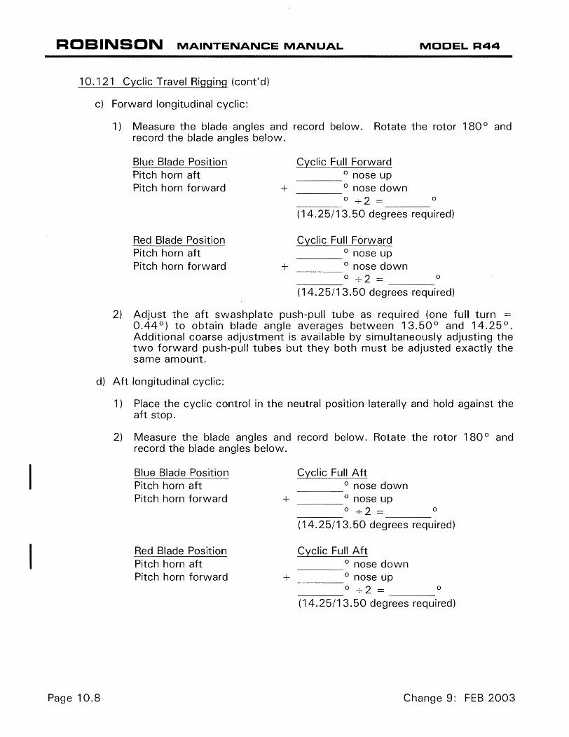
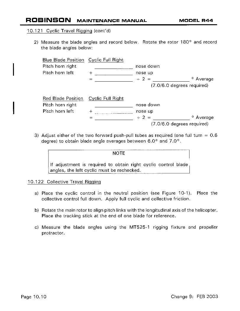
10.121 Cyclic Travel Rigging . . . . . . . . . . . . . . . . . . . . . . . . 10.7
10.122 Collective Travel Rigging . . . . . . . . . . . . . . . . . . . . . 10.10
10.130 Tail Rotor Flight Controls . . . . . . . . . . . . . . . . . . . . . . . . . . 10.11
10.131 Pedals . . . . . . . . . . . . . . . . . . . . . . . . . . . . . . . . . . 10.11
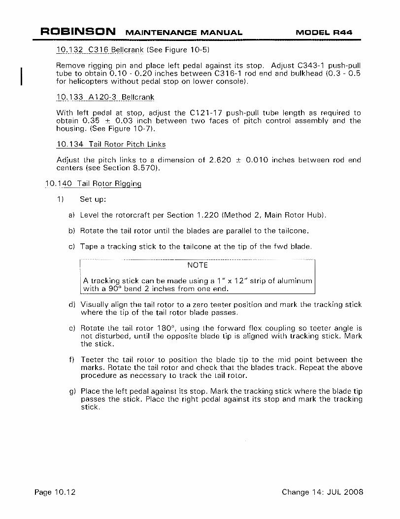
10.132 C316 Bell Crank . . . . . . . . . . . . . . . . . . . . . . . . . . . 10.12
10.133 A120-3 Bell Crank . . . . . . . . . . . . . . . . . . . . . . . . . . 10.12
10.134 Tail Rotor Pitch Links . . . . . . . . . . . . . . . . . . . . . . . . 10.12
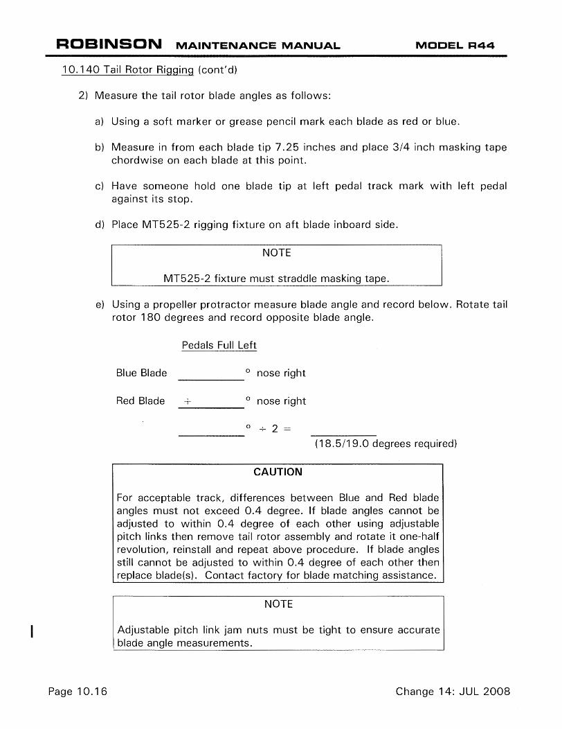
10.140 Tail Rotor Rigging . . . . . . . . . . . . . . . . . . . . . . . . . . . . . . . 10.12
10.150 Throttle Correlation Rigging . . . . . . . . . . . . . . . . . . . . . . . . 10.19
10.160 Actuator Rigging . . . . . . . . . . . . . . . . . . . . . . . . . . . . . . . 10.19
10.200 Track and Balance . . . . . . . . . . . . . . . . . . . . . . . . . . . . . . . . . . . 10.19
10.210 Equipment Requirements . . . . . . . . . . . . . . . . . . . . . . . . . . 10.20
10.220 Equipment Installation . . . . . . . . . . . . . . . . . . . . . . . . . . . . 10.20
10.221 Main Rotor Equipment Installation . . . . . . . . . . . . . . . 10.20
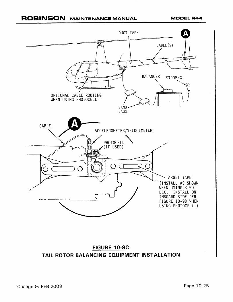
10.222 Tail Rotor Equipment Installation . . . . . . . . . . . . . . . . 10.24
10.230 Main Rotor Track and Balance Procedure . . . . . . . . . . . . . . . 10.27
10.231 Main Rotor Balance Adjustments . . . . . . . . . . . . . . . . 10.28
10.232 Main Rotor Pitch Link Adjustment . . . . . . . . . . . . . . . 10.28
10.233 Main Rotor Blade Trim Tab Adjustment . . . . . . . . . . . 10.32
10.234 Main Rotor Track and Balance Trouble-Shooting . . . . . 10.33
Page 10.ii DEC 2011
CHAPTER 10
RIGGING, TRACK AND BALANCE (Continued)
Section Title Page
10.240 Tail Rotor Balance Procedures . . . . . . . . . . . . . . . . . . . . . . 10.34
10.250 Autorotational RPM Adjustment . . . . . . . . . . . . . . . . . . . . . 10.36
CHAPTER 10
RIGGING, TRACK AND BALANCE
10.000 Rigging, Track and Balance
10.001 Introduction
This section contains procedures necessary to rig the main rotor flight controls, tail rotor flight controls and throttle correlation. The track and balance procedures in this section are to be used in conjunction with Chadwick-Helmuth balancing equipment instructions.
WARNING
A rotor which is smooth after balancing but then goes out of balance again within a few flights is suspect and must be examined by a RHC-authorized component overhaul facility before further flight.
10.002 Rod End Adjustment Procedures
The following procedure is standard for adjustment of rod ends:
1. Loosen palnut and jam nut on rod end shank.
2. Screw rod end in or out of push-pull tube or pitch link as required to obtain proper rigging adjustment.
3. After any rod end adjustment, verify rod end threaded shank blocks passage of 0.020 inch diameter wire thru the witness hole in the push-pull tube or pitch link as shown in Figure 2-1. When no witness hole is provided, refer to Figure 2-1 for maximum rod end extension.
4. Position rod ends to allow as much push-pull tube or pitch link rotation as possible without binding. Refer to Figure 2-1A.
5. C258-1 main rotor pitch links may require adjustment during rigging or tracking. For collective adjustments, both pitch links must be adjusted exactly the same.
Each main rotor pitch link has coarse, medium, and fine length adjustments:
a. Coarse length adjustments are made by rotating coarse-threaded section of pitch link. Disconnect upper rod end from blade and loosen jam nut in middle of pitch link only. Increase blade angle by unscrewing C258-2 fitting from lower pitch link. Decrease angle by screwing fitting into lower pitch link. One full turn changes blade angle by approximately 0.88º.
b. Medium length adjustments are made by rotating upper rod end only. Disconnect rod ends from blade and loosen rod end jam nuts. Increase blade angle by unscrewing rod end from pitch link. Decrease angle by screwing rod end into pitch link. One full rod end turn changes blade angle by approximately 0.48º.
DEC 2011 Page 10.1

10.002 Rod End Adjustment Procedures (cont’d)
c. Fine length adjustments are made by rotating only the C258-2 fitting. Upper and lower rod ends remain connected. Loosen jam nuts at upper rod end and in the middle of pitch link. Increase blade angle by screwing fitting out of lower pitch link. Decrease blade angle by screwing fitting into lower pitch link. One full turn of fitting changes blade angle approximately 0.40º.
6. Torque jam nuts and palnuts per Section 1.320 and torque stripe per Figure 2-1.
10.100 Rigging
10.110 Main Rotor Flight Controls
10.111 Cyclic Controls
The cyclic control travel is non-adjustable and is controlled by the A211-3 stop plate attached to cyclic box assembly.
NOTE
The following push-pull tube assemblies and fork assembly between the keel panels are to be adjusted to the noted center-to-center dimensions:
C121-1 = 51.03 ± 0.03 inches C121-3 = 32.54 ± 0.03 inches C121-19 = 31.38 ± 0.03 inches A205-3, -5 = 03.80 ± 0.03 inches
a) Refer to Figure 10-1. Place cyclic control in neutral position. Cyclic neutral position is 7.0 inches to the right of full-left travel and at mid-point of total fore and aft travel or use MT559-1 rigging blocks. Place collective control full down.
b) Apply full cyclic and collective friction.
NOTE
Care must be taken not to move cyclic control from neutral position.
Page 10.2 DEC 2011


10.234 Main Rotor Track and Balance Troubleshooting
Symptom Probable Cause Correction
1. Excessive Cyclic or Stick Shake
Rough or binding A205-5 fork assembly (upper swashplate).
Replace or refer to Section 8.6.
Brinelled spindle bearing(rough movement).
Send blade(s) to RHC or Service Center for spindle bearing replacement.
Rough blade surface (chipped paint). Repair blades per Section 9.130.
Rough or binding pitch links. Replace pitch link rod ends
MR blade boot misaligned. Realign or replace boot per Sections 9.113 & 9.114.
MR teeter or coning hinge binding. Replace bearings per Section 9.126.
MR blade trim tabs bent upward. Bend trim tabs evenly down per Section 10.233.
Blade mismatch. Send blade(s) to RHC for replacement.
2. Excessive Ship Vibration
MR out of track and balance. Track and balance per Section 10.230.
MR teeter or coning hinge friction. Adjust hinge friction per Section 9.124.
MR teeter or coning hinge binding. Replace bearings per Section 9.126.
Brinelled spindle bearing(rough movement).
Send blade(s) to RHC or Service Center for spindle bearing replacement.
MR teeter hinge bearings worn. Replace bearings per Section 9.126.
3. Excessive Cyclic Stick Forces
Brinelled spindle bearing(rough movement).
Send blade(s) to RHC or Service Center for spindle bearing replacement.
4. Intermittent Blade Track Picture
MR teeter or coning hinge friction Adjust hinge friction per Section 9.124.
MR coning hinge binding. Replace bearings per Section 9.126.
MR teeter hinge not "broken-in." Track and balance per Section 10.230. Adjust track to minimize error.
Brinelled spindle bearing(rough movement).
Send blade(s) to RHC or Service Center for spindle bearing replacement.
5. Radical Changes to Cyclic Trim
MR teeter hinge bearings worn. Replace bearings per Section 9.126.
Brinelled spindle bearing(rough movement).
Send blade(s) to RHC for spindle bearing replacement.
6. Lateral Intermittent Ship Vibration
Engine misfiring due to malfunction in spark plugs, ignition leads, magneto, or engine not “broken-in.”
Refer to Textron-Lycoming Maintenance Instructions.
7. 4 per second Fore/Aft Oscillation
Aircraft CG out of limits. Operate aircraft within CG envelope.
Deteriorated / contaminated main gearbox rubber mount(s).
Replace main gearbox mounts.
DEC 2011 Page 10.33

Page 10.34 DEC 2011
10.240 Tail Rotor Balance Procedure
Refer to specific manufacturer’s installation instructions when using balancing equipment other than Chadwick-Helmuth Vibrex system.
Install Chadwick-Helmuth equipment per Section 10.222. Set Function Knob on Balancer to appropriate channel. Set balancer RPM Range knob to X10 and set RPM to 231. With helicopter running with governor ON, view tail rotor assembly with Strobex. Tune Balancer while viewing target tape and adjusting RPM dial on Balancer. Record clock angle and IPS on tail rotor balance chart. Adjust as required until balance is less than 0.2 IPS.
Spanwise balance adjustments for C029-1 square-tip blades are made by adding, subtracting, or exchanging weights under the removable tip cover. Use C134-1 or -2 tip weights or AN960-8 or -8L washers. -8L washers may be trimmed as a very fine adjustment.
Spanwise balance adjustments for C029-2 and C029-3 round-tip blades are made by exchanging different diameter washers under nut securing blade’s outboard retaining bolt. The bolt has sufficient length to allow necessary spanwise weight changes; verify 2-4 threads protruding past nut after torquing per Section 1.320.
Chordwise balance is adjusted by adding, subtracting, or exchanging A141-14, A214-3, NAS1149F0463P/F0432P, or NAS1149D0463J/D0432J washers under nut securing blade’s pitch link attaching bolt. Change pitch link attaching bolt length as required for proper thread engagement (see Section 1.310, refer to IPC for allowable lengths).

DEC 2011 Page 10.34A
FIGURE 10-14 C008-9 TAIL ROTOR ASSEMBLY DYNAMIC BALANCE CHART
DATE SERIAL NO.
PAGE
BALANCE
CLOCK IPS
ADJUSTMENT:
CLOCK IPS
ADJUSTMENT:
CLOCK IPS
ADJUSTMENT:
CLOCK IPS
ADJUSTMENT:
CHORDWISE WEIGHTS
(1) NAS1149F0463P Washer = (2) NAS1149F0432P Washers
(1) A214-3 Washer = (3.5) NAS1149F0432P Washers
(1) A141-14 Washer = (5) NAS1149F0432P Washers
SPANWISE WEIGHTS
(1) C141-23 Washer = (3.5) NAS1149F0663P Washers
(1) C141-24 Washer = (7) NAS1149F0663P Washers
(2) NAS1149F0632P (1) NAS1149F0663P Washer
C008-9 TAIL ROTOR ASSEMBLY
Page 10.34B DEC 2011
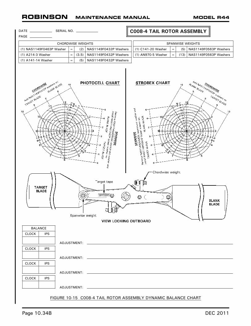
FIGURE 10-15 C008-4 TAIL ROTOR ASSEMBLY DYNAMIC BALANCE CHART
DATE SERIAL NO.
PAGE
BALANCE
CLOCK IPS
ADJUSTMENT:
CLOCK IPS
ADJUSTMENT:
CLOCK IPS
ADJUSTMENT:
CLOCK IPS
ADJUSTMENT:
CHORDWISE WEIGHTS
(1) NAS1149F0463P Washer = (2) NAS1149F0432P Washers
(1) A214-3 Washer = (3.5) NAS1149F0432P Washers
(1) A141-14 Washer = (5) NAS1149F0432P Washers
SPANWISE WEIGHTS
(1) C141-20 Washer = (5) NAS1149F0563P Washers
(1) AN970-5 Washer = (13) NAS1149F0563P Washers
C008-4 TAIL ROTOR ASSEMBLY

DEC 2011 Page 10.35
FIGURE 10-16 C008-2 TAIL ROTOR ASSEMBLY DYNAMIC BALANCE CHART
DATE SERIAL NO.
PAGE
BALANCE
CLOCK IPS
ADJUSTMENT:
CLOCK IPS
ADJUSTMENT:
CLOCK IPS
ADJUSTMENT:
CLOCK IPS
ADJUSTMENT:
CHORDWISE WEIGHTS
(1) NAS1149F0463P Washer = (2) NAS1149F0432P Washers
(1) A141-14 Washer = (5) NAS1149F0432P Washers
SPANWISE WEIGHTS
(1) NAS1149FN832P = (2) NAS1149FN816P Washers
(1) C134-1 Weight = (14) NAS1149FN816P Washers
C008-2 TAIL ROTOR ASSEMBLY

Intentionally Blank
Page 10.35A DEC 2011


