section k wastewater collection system...haldimand county design criteria section k – wastewater...
TRANSCRIPT

HALDIMAND COUNTY
DESIGN CRITERIA
SECTION K
WASTEWATER COLLECTION SYSTEM
Reviewed/Revised August 2018

HALDIMAND COUNTY DESIGN CRITERIA
SECTION K – WASTEWATER COLLECTION SYSTEM PAGE 1
_________________________________________________________________________________
K 1.00 GENERAL
All sanitary sewer and appurtenances are to be designed and
constructed in accordance with current Ministry of the Environment and
Climate Change (MOECC) Guidelines for the Design of Sewage Works
and Ontario Provincial Standards Drawings and Specifications.
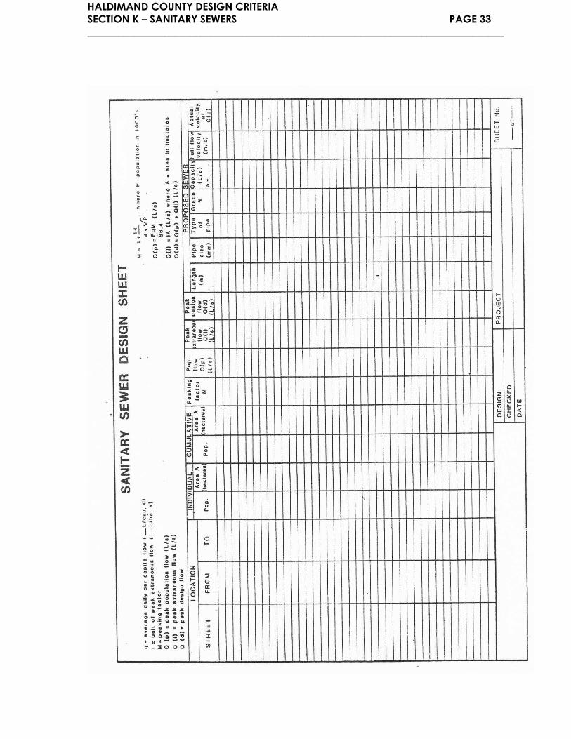
Design computations for sanitary sewer systems must be completed on
a standard calculation sheet in the format recommended by MOECC
guidelines (attached at the end of this section).
Sanitary sewers are not permitted to accept foundation or weeping tile,
sump pumps or roof drainage.
All sewers shall be designed for an embankment condition.
In cases of new subdivisions, the consulting Engineer is required to
establish the geodetic invert elevations and ties of all sanitary sewer
connections at street line and to make this information available on the
as-built plans to Haldimand County.
K 2.00 DESIGN FLOW
K 2.01 AVERAGE DRY WEATHER FLOW
Type of Development
Equivalent Population
Density
(persons/hectare)
Unit Sewage Flow
m3/capita/day m³/s/person
Residential
Single Family 55 0.410 4.7 x 10⁶־
Semi-detached, duplex
& 4-plex 100 0.275 3.2 x 10⁶־
Townhouse, maisonette, 6
story apartment or less 135 0.275 3.2 x 10⁶־
Apartments (over 6 stories
high) 285 0.275 3.2 x 10⁶־

HALDIMAND COUNTY DESIGN CRITERIA
SECTION K – WASTEWATER COLLECTION SYSTEM PAGE 2
_________________________________________________________________________________
Industrial / Commercial / Institutional (ICI)
Schools
a) Boarding schools
b) Day schools with
cafeterias
c) Day schools without
cafeterias
0.3
0.08
0.06
3.5 x 10⁻⁶
0.9 x 10⁻⁶
0.7 x 10⁻⁶
m³/day/ha m³/s/ha
Light Commercial Areas 90 40.5 4.688 x 10⁻⁴
Community Services 40 18.0 2.083 x 10⁻⁴
Light Industrial Areas 125 56.25 6.510 x 10⁻⁴
Hospitals 4 persons/bed 1.8m³/day/bed 2.080 x 10⁵־
m³/s/bed
These population densities are guidelines only. Individual studies shall
be made for special commercial establishments, major commercial
areas and special industrial and major industrial areas.
For recommended maximum dwelling unit densities see K 11.0 (b).
The design of sanitary sewers should be based on the ultimate sewage
flows.
K 2.02 PEAK SANITARY FLOW FACTOR
The peak sanitary flow will be derived by applying the ratio established
by the Harmon formula to the average sanitary flow for residential and
community services area as follows: Refer to peaking factor table at
the end of this section.
𝑀 = 1 +14
4 + 𝑃0.5
2 ≤ 𝑀 ≤ 5
Where 𝑀 = ratio of peak flow to average flow
𝑃 = the tributary population in thousands
For commercial and industrial land uses, the peaking factor will be
determined from a modified Harmon formula as follows:
𝑀𝑒 = 0.8(1 +14
4 + 𝑃𝑒0.5)

HALDIMAND COUNTY DESIGN CRITERIA
SECTION K – WASTEWATER COLLECTION SYSTEM PAGE 3
_________________________________________________________________________________
Where 𝑀𝑒 = ratio of peak flow to average flow
𝑃𝑒 = equivalent tributary population in thousands
When tributary area consists of combined residential, industrial and
commercial land uses, the peaking factor shall be calculated using the
modified Harmon formula where 𝐾𝑎𝑣 shall be determined as follows:
𝑀𝑎𝑣 = 𝐾𝑎𝑣(1 +14
4 + (𝑃 + 𝑃𝑒)0.5)
Where 𝐾𝑎𝑣 = 𝐴𝑅 + 0.8(𝐴𝐿 + 𝐴𝐶)
𝐴𝑅 = residential area
𝐴𝐿 = industrial area
𝐴𝐶 = commercial area
K 2.03 INFILTRATION ALLOWANCE
Except under unusual circumstances, infiltration allowance shall be
determined at 2.3 x 10⁻⁴ m³/s/ha (19.872m3/day/ha) for all land use
types.
K 2.04 DESIGN FLOW
Design Flow = Av. Dry Weather Flow x Av. Peak Sanitary Flow Factor +
Infiltration Allowance.
K 3.00 PIPE SIZE
To determine the pipe size and its capacity, Manning’s Formula shall be
used. Manning’s Formula is expressed as:
Q = 1/n x R ⅔ x S ½ x A
Where Q = design flow (m³/sec)
n = Manning Roughness coefficient factor (dimensionless)
R = hydraulic radius (m)
S = slope (m/m)
A = section area of flow (m²)
For all smooth walled pipe, the coefficient of roughness shall be 0.013.
HALDIMAND COUNTY DESIGN CRITERIA
SECTION K – WASTEWATER COLLECTION SYSTEM PAGE 4
_________________________________________________________________________________
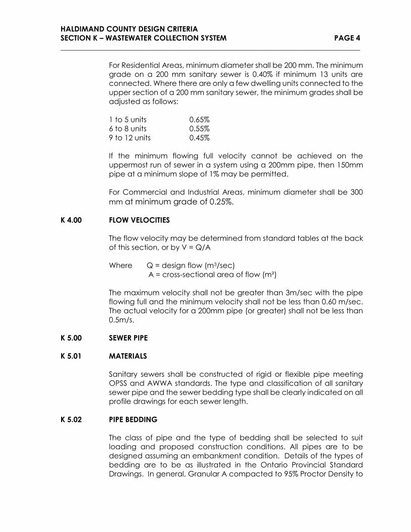
For Residential Areas, minimum diameter shall be 200 mm. The minimum
grade on a 200 mm sanitary sewer is 0.40% if minimum 13 units are
connected. Where there are only a few dwelling units connected to the
upper section of a 200 mm sanitary sewer, the minimum grades shall be
adjusted as follows:
1 to 5 units 0.65%
6 to 8 units 0.55%
9 to 12 units 0.45%
If the minimum flowing full velocity cannot be achieved on the
uppermost run of sewer in a system using a 200mm pipe, then 150mm
pipe at a minimum slope of 1% may be permitted.
For Commercial and Industrial Areas, minimum diameter shall be 300
mm at minimum grade of 0.25%.
K 4.00 FLOW VELOCITIES
The flow velocity may be determined from standard tables at the back
of this section, or by V = Q/A
Where Q = design flow (m3/sec)
A = cross-sectional area of flow (m²)
The maximum velocity shall not be greater than 3m/sec with the pipe
flowing full and the minimum velocity shall not be less than 0.60 m/sec.
The actual velocity for a 200mm pipe (or greater) shall not be less than
0.5m/s.
K 5.00 SEWER PIPE
K 5.01 MATERIALS
Sanitary sewers shall be constructed of rigid or flexible pipe meeting
OPSS and AWWA standards. The type and classification of all sanitary
sewer pipe and the sewer bedding type shall be clearly indicated on all
profile drawings for each sewer length.
K 5.02 PIPE BEDDING
The class of pipe and the type of bedding shall be selected to suit
loading and proposed construction conditions. All pipes are to be
designed assuming an embankment condition. Details of the types of
bedding are to be as illustrated in the Ontario Provincial Standard
Drawings. In general, Granular A compacted to 95% Proctor Density to
HALDIMAND COUNTY DESIGN CRITERIA
SECTION K – WASTEWATER COLLECTION SYSTEM PAGE 5
_________________________________________________________________________________
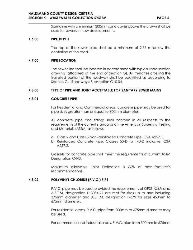
Springline with a minimum 300mm sand cover above the crown shall be
used for sewers in new developments.
K 6.00 PIPE DEPTH
The top of the sewer pipe shall be a minimum of 2.75 m below the
centerline of the road.
K 7.00 PIPE LOCATION
The sewer line shall be located in accordance with typical road section
drawing (attached at the end of Section G). All trenches crossing the
travelled portion of the roadway shall be backfilled as according to
Section G – Roadways; Subsection G10.04.
K 8.00 TYPE OF PIPE AND JOINT ACCEPTABLE FOR SANITARY SEWER MAINS
K 8.01 CONCRETE PIPE
For Residential and Commercial areas, concrete pipe may be used for
pipe sizes greater than or equal to 300mm diameter.
All concrete pipe and fittings shall conform in all respects to the
requirements of the current standards of the American Society of Testing
and Materials (ASTM) as follows:
a) Class 2 and Class 3 Non-Reinforced Concrete Pipe, CSA A257.1.
b) Reinforced Concrete Pipe, Classes 50-D to 140-D inclusive, CSA
A257.2.
Gaskets for concrete pipe shall meet the requirements of current ASTM
Designation C443.
Maximum allowable Joint Deflection is 66% of manufacturer’s
recommendations.
K 8.02 POLYVINYL CHLORIDE (P.V.C.) PIPE
P.V.C. pipe may be used, provided the requirements of OPSS, CSA and A.S.T.M. designation D-3034-77 are met for sizes up to and including
375mm diameter and A.S.T.M. designation F-679 for sizes 450mm to
675mm diameter.
For residential areas, P.V.C. pipe from 200mm to 675mm diameter may
be used.
For commercial and industrial areas, P.V.C. pipe from 300mm to 675mm

HALDIMAND COUNTY DESIGN CRITERIA
SECTION K – WASTEWATER COLLECTION SYSTEM PAGE 6
_________________________________________________________________________________
diameter may be used.
All joints using flexible Electrometric seals shall conform to current
requirements of A.S.T.M. designation D-3212.
Maximum allowable Joint Deflection is 66% of manufacturer’s
recommendations.
K 9.00 CURVED SEWERS
Generally, curved sanitary sewers should be avoided. In case where
suitability and efficiency of design suggest doing so, County will
determine approval condition on a site-specific basis.
K 9.01 REINFORCED CONCRETE PIPE
Radius pipe (also referred to as beveled or mitered pipe) may be used
for short radius bends. The pipe shall meet the requirements of CSA
257.2 or A.S.T.M C-76 for reinforced concrete radius pipe for sizes 525mm
- 3050mm diameter.
NOTE: for flat curves (long radius), straight pipe with joint deflections is
permissible. Maximum joint deflection shall be 13mm to conform to CSA
257.3 or A.S.T.M C-443.
K 9.02 P.V.C. PIPE
The allowable minimum curve radius recommended by the
manufacturer shall not be exceeded. Deflection in the joint is not
allowed.
Saddle type connections are not permitted. Tee connections are
permitted, but the designer must take into consideration the tangent
lengths of the tee connections when calculating the minimum
achievable radius.
K 10.00 MANHOLE TYPES
Manholes may be constructed of pre-cast or poured concrete. O.P.S.D.
details shall be used for manhole design where applicable. Although
these Standard Drawings provide details for manholes up to certain
maximum depths and sizes, the consulting Engineer shall analyse,
individually, each application of the standards relative to soil conditions,
loading and other pertinent factors to determine structural suitability. In
all cases where the Standard Drawings are not applicable, the
manholes shall be individually designed and detailed. Working drawings
must be provided for poured-in-place structures.
HALDIMAND COUNTY DESIGN CRITERIA
SECTION K – WASTEWATER COLLECTION SYSTEM PAGE 7
_________________________________________________________________________________
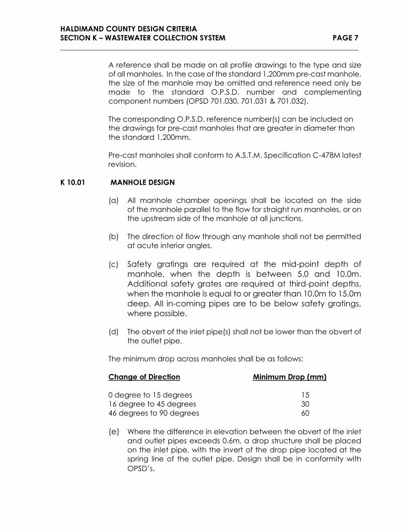
A reference shall be made on all profile drawings to the type and size
of all manholes. In the case of the standard 1,200mm pre-cast manhole,
the size of the manhole may be omitted and reference need only be
made to the standard O.P.S.D. number and complementing
component numbers (OPSD 701.030, 701.031 & 701.032).
The corresponding O.P.S.D. reference number(s) can be included on
the drawings for pre-cast manholes that are greater in diameter than
the standard 1,200mm.
Pre-cast manholes shall conform to A.S.T.M. Specification C-478M latest
revision.
K 10.01 MANHOLE DESIGN
(a) All manhole chamber openings shall be located on the side
of the manhole parallel to the flow for straight run manholes, or on
the upstream side of the manhole at all junctions.
(b) The direction of flow through any manhole shall not be permitted
at acute interior angles.
(c) Safety gratings are required at the mid-point depth of
manhole, when the depth is between 5.0 and 10.0m.
Additional safety grates are required at third-point depths,
when the manhole is equal to or greater than 10.0m to 15.0m
deep. All in-coming pipes are to be below safety gratings,
where possible.
(d) The obvert of the inlet pipe(s) shall not be lower than the obvert of
the outlet pipe.
The minimum drop across manholes shall be as follows:
Change of Direction Minimum Drop (mm)
0 degree to 15 degrees 15
16 degree to 45 degrees 30
46 degrees to 90 degrees 60
(e) Where the difference in elevation between the obvert of the inlet
and outlet pipes exceeds 0.6m, a drop structure shall be placed
on the inlet pipe, with the invert of the drop pipe located at the
spring line of the outlet pipe. Design shall be in conformity with
OPSD’s.

HALDIMAND COUNTY DESIGN CRITERIA
SECTION K – WASTEWATER COLLECTION SYSTEM PAGE 8
_________________________________________________________________________________
(f) All sewer manholes shall be benched to the obvert of the outlet
pipe on a vertical projection from the spring line of the sewer.
(g) The minimum width of benching in all manholes shall be 230mm.
(h) Manholes in boulevards shall be located, wherever possible, a
minimum of 1.5m from the face of curb or other utilities or street
furniture.
The maximum spacing between manholes shall be as follows:
Pipe Size Maximum Manhole Spacing
200-300mm 95 metres
375mm to 750mm 100 metres
825mm to 1200mm 125 metres
1200mm and over 150 metres
(i) Manholes are required at all mainline pipe junctions, and at any
changes in grade or alignment.
K 10.02 GRADES FOR MANHOLE FRAME AND COVERS
All manholes located within the travelled portion of roadway shall have
the rim elevation set flush with the surface of the base course asphalt.
The adjustment of the frame and cover shall be completed in
accordance with the details provided in the Ontario Provincial
Standard Drawings.
After final application of surface asphalt the manhole frame and grates
shall be adjusted to surface elevation through a poured in place
concrete ring. The concrete ring shall be constructed through coring
through the full depth of the asphalt. The frame and grate shall be set
to match the elevation and cross fall of the final asphalt grade. A
sonotube form shall be installed as to match the manhole chimney
opening. The concrete shall be placed neat to the edge of the asphalt
core and shall be trowelled as to match the existing lines and grade of
the asphalt surface. The surface of the concrete shall receive a brushed
finish.
Alternatively a Mueller model “the Adjustable” or equivalent manhole
frame and cover may be used. Installation of the manhole frame and
grate shall be as per the manufacturers instructions. Units shall consist of
three components, a cover, frame and guide.
Watertight manhole lids are required when sanitary maintenance holes
are located within overland storm routes and/or under sanitary
surcharge condition.

HALDIMAND COUNTY DESIGN CRITERIA
SECTION K – WASTEWATER COLLECTION SYSTEM PAGE 9
_________________________________________________________________________________
K 11.00 CONNECTIONS FROM SEWER TO STREET LINE
Only one (1) sanitary sewer connection per property shall be permitted,
unless authorized by Haldimand County General Manager of Public
Works.
Where an existing sanitary sewer main is to remain in place the
connection of a sanitary service lateral may be made at an existing
manhole, or directly to the sanitary sewer main if the size of the
connection is less than or equal to half of the size of the sanitary sewer
main.
If the sanitary service lateral connection size is greater than one half the
size of the sanitary sewer main, the connection must be made to a
manhole, existing or new. A direct connection to the sanitary sewer
main may be accepted with the use of an approved manufactured
tee. All connections to existing pipes or manholes shall be completed
through coring the pipe or manhole. No intrusions shall be left in the
pipe.
Where the sanitary service lateral is to tie into an existing wastewater
collection system manhole, an exterior drop structure configuration is to
be constructed. Reference OPSD 1003.020 – Cast-In-Place
maintenance Hole Drop Structure Wye.
Where a new sanitary main is being constructed all connections shall
be made by installation of manufactured tees at all service locations.
In all cases, the invert of the lateral pipe must be above the spring line
of the main pipe.
P.V.C Pipe must be used for service connections. For P.V.C. service
connections, minimum SDR28 shall be used.
If necessary, concrete encased risers shall be provided for connection
with the main sewer.
Connection Requirements:
Development
Minimum Sewer
Lateral Size
(mm)
Desirable
Lateral Slope
(%)
Minimum
Lateral Slope
(%)
Minimum
Cover at
Property Line
(m)
Residential
Single family
Semi-detatched
100 2.0 1.0 2.15

HALDIMAND COUNTY DESIGN CRITERIA
SECTION K – WASTEWATER COLLECTION SYSTEM PAGE 10
_________________________________________________________________________________
Multi-Residential 150 See subsection a) Multi-
Residential below 2.15
Industrial
Commercial
Institutional
150 2.0 1.5 2.15
For all sanitary service laterals greater than thirty (30) meters in length,
an approved property line cleanout is required and shall be shown on
all design drawings.
Industrial, commercial and institutional developments require a
property line monitoring manhole on the sewer lateral service as per the
County’s Sewer Use Bylaw.
Joints and bedding shall be equivalent to the joints and bedding
specified for sewer pipe.
Until the sanitary sewer lateral pipe from the property line to the building
has been installed, the location of the end of all lateral connections
from the sanitary sewer main to the property line shall be marked by a
50mm x 100mm wooden stake, 2 meters long, projecting one meter
above the ground with the top 300mm painted with fluorescent green
colour conforming to Canadian General Standards Board (C.G.S.B.)
603-401.
(a) Multi-Residential: In multiple family blocks in residential areas,
the connection shall meet the following requirements:
Diameter of Drain
(mm)
Slope of Drain
2.0% 4.0%
(Max. No. of Fixture Units per conn.)
150 840 1000
200 1920 2300
250 3500 4200
300 5600 6700
375 10000 12000
Maximum Dwelling Units Densities
4-plex 25 units/hectare
Townhouse 37 units/hectare
Maisonette 45 units/hectare
Apartments 124 units/hectare
Loading – 20 fixtures units/dwelling unit

HALDIMAND COUNTY DESIGN CRITERIA
SECTION K – WASTEWATER COLLECTION SYSTEM PAGE 11
_________________________________________________________________________________
To Use the Chart
i) Determine dwelling density and total area of block
ii) Calculate total number of fixture units from:
Area x Dwelling units/hectare x 20
iii) Select connection size and grade from chart.
iv) The minimum requirement shall be 150mm diameter at 1.5%
grade.
K 11.01 PRIVATE SIDE SEWER LATERALS
The following requirements apply to all private side laterals connecting
a building drain to a municipal sanitary sewer in Haldimand County.
MATERIALS
When these materials are used they must be installed as per the OBC
and this Design Criteria.
a) PVC SDR 28 with Gasket Fittings conforming to CAN/CSA-B182.2
is the preferred choice of sewer lateral pipe (as a minimum)
b) PVC SDR 26 with Gasket Fittings conforming to CAN/CSA-B182.2
is acceptable as well.
As per 7.2.5.10.(2) all plastic pipe used underground shall have a
stiffness equal or greater than 320 kPa.
INSTALLATION
All piping when installed for a sewer lateral must be installed as per
manufacturers instructions. Manufactures requirements must be
followed for foundation, bedding, haunching, initial and final backfill of
piping installed for sewer laterals. Any installation that is performed in a
manner that does not meet manufacturers installation requirements will
be deemed for the purpose of this design criteria not to meet the
Ontario Building Code.
MINIMUM TESTING REQUIREMENTS
All sewer laterals will be pressure tested as per OBC 7.3.6.4.(1)(2)(a)(b)
Water Test or 7.3.6.5.(1)(a)(b) Air Test. A flow test will be conducted as
well to ensure grade and to confirm there are no blockages in the
lateral or lateral extension. A test “T” or “Y” fitting will be required to be
installed in the sewer lateral immediately upstream of the lateral
extension. After the test has passed the required test fitting shall be

HALDIMAND COUNTY DESIGN CRITERIA
SECTION K – WASTEWATER COLLECTION SYSTEM PAGE 12
_________________________________________________________________________________
capped by an approved fitting and will seen by the inspector before
backfill has been completed.
INSPECTIONS
Inspections by the Haldimand County Building Department shall be
conducted and will consist of two separate inspections. The first required
inspection shall be to confirm there is proper bedding for the lateral, the
correct pipe has been installed, the approved method of joining has
been adhered to and that the pipe has the correct grade as per O.B.C
requirements. The second required inspection will be to view the
pressure test, flow test, an initial backfill of 300 mm of carefully placed
clean fill or gravel (to ensure there are no large chunks and/or frozen
earth, rocks, boulders etc. over the pipe), and to witness the permanent
capping of the test fitting. It will be accepted that both inspections may
be the same day and within a short period of time if required.
K 12.00 SEWAGE FORCEMAINS
K 12.01 TYPE OF PIPE AND JOINT ACCEPTABLE FOR SEWAGE FORCEMAINS
a) Ductile Iron Cement Lined Pipe
Ductile iron cement lined pipe with Tyton joints or equivalent may
be used. The current requirement of AWWA C150 and AWWA
C104 shall apply to all classes of ductile iron pipe.
b) Poly-vinyl Chloride (P.V.C.) Pipe
For sizes up to 600mm, P.V.C. pipe with gasketed joints may be
used. The current requirements of CSA B137.3 shall apply to all
classes of P.V.C. pipe.
c) Polyethylene (P.E.) Pressure Pipe
Polyethylene pressure pipe with joints made by thermal fusion or
by mechanical means may be used. The polyethylene resin
compound used in the pipe shall conform to current ASTM
Designation D1248. The pipe shall be manufactured to CGSB 41-
GP-25M specifications.
d) Reinforced Concrete Pressure Pipe
For sizes 400mm and over, reinforced concrete pressure pipe with

HALDIMAND COUNTY DESIGN CRITERIA
SECTION K – WASTEWATER COLLECTION SYSTEM PAGE 13
_________________________________________________________________________________
gasketed joints may be used as indicated below:
Pre-tensioned concrete cylinder pipe conforming to AWWA
C-303.
Pre-stressed concrete lined cylinder pipe conforming to AWWA C-
301.
K 12.02 PIPE SIZE
The forcemain shall be sized to have flow velocity in the range of 0.8 to
2.5 m/s with the lower limit being preferred for the initial phase.
However, the minimum size shall not be less than 100mm.
K 12.03 PIPE DEPTH
The top of the forcemain shall have a minimum of 1.7m cover. On open
ditch or unimproved road, increased cover shall be provided to allow
for future road improvement or lowering when urbanization takes place.
K 12.04 SYSTEM DESIGN
a) Haldimand County’s preference is to avoid thrust blocks if possible,
giving preference to appropriate mechanical restraint. All
forcemains and thrust blocks shall be designed to withstand the
maximum operating pressure plus the transient pressure to which
they will be subjected.
b) All forcemains shall be equipped with a suitably valved
connection to permit connection of a portable pump should
pumping stations need to be by-passed during emergencies or
major modifications.
c) Air release valves suitable for use with sewage shall be positioned
at all forcemain high points. The valves shall be of low-pressure
double acting type.
d) All plugs, tees, and bends will have approved thrust blocks (at
Haldimand County discretion) or suitable alternatives i.e. non-
corrosive clamps and bell bolt joints, restraining type glands rings.
e) The bedding requirements for the forcemains will depend upon
the type and class of pipe used. As a minimum requirement,
forcemain pipe shall be laid on 150mm of selected native material
bedding. However, each installation shall be reviewed on a site
specific basis.

HALDIMAND COUNTY DESIGN CRITERIA
SECTION K – WASTEWATER COLLECTION SYSTEM PAGE 14
_________________________________________________________________________________
f) The type of backfill material will usually be determined from the
location of mains within the R.O.W. Under road pavement,
granular backfill will be provided.
K 12.05 PRIVATE FORCEMAINS
It is the preference of the County that all structures be connected to the
County’s sanitary sewer system by means of gravity connections.
There are situations where gravity access to existing County sanitary
sewers is not feasible. Where these instances arise, an application must
be made to the Water and Wastewater Operations Division requesting
the installation of a private sanitary forcemain. Each application will be
reviewed on a site-specific basis. A permit for the installation of a private
forcemain will only be allowed with the written approval of the Manager
of Water and Wastewater Operations.

HALDIMAND COUNTY DESIGN CRITERIA
SECTION K – SANITARY SEWERS PAGE 15
____________________________________________________________________________________________________________________
SANITARY SEWERS -PREFERRED DESIGN RANGE
Concrete
Pipe P.V.C. Pipe Truss Pipe
Polyethylene
(P.E.) Pipe Ductile Iron Pipe
RESIDENTIAL MAINS Dia. >300mm 200mm to 675mm 200 to 375mm
Joint Bell &
Spigot Gasket joint Solvent Weld
COMMERCIAL MAINS Dia. >300mm 300-675 Not Allowed
Joint Bell &
Spigot Gasket joint Not Allowed
INDUSTRIAL MAINS Dia. >600mm 375-675 Not Allowed
Joint Bell &
Spigot Gasket joint Not Allowed
SERVICE LATERALS Dia. Not
Allowed
>100mm Res. Only
>150mm I/C/I Not Allowed
Joint Not
Allowed Gasket joint Not Allowed
FORCEMAINS Dia. >400mm
pressured <600mm Not Allowed <600mm
Joint
Bell &
Spigot with
gasket
Plas-tyton gasket
joint Not Allowed Butt fusion

HALDIMAND COUNTY DESIGN CRITERIA
SECTION K – SANITARY SEWERS PAGE 16
_________________________________________________________________________________
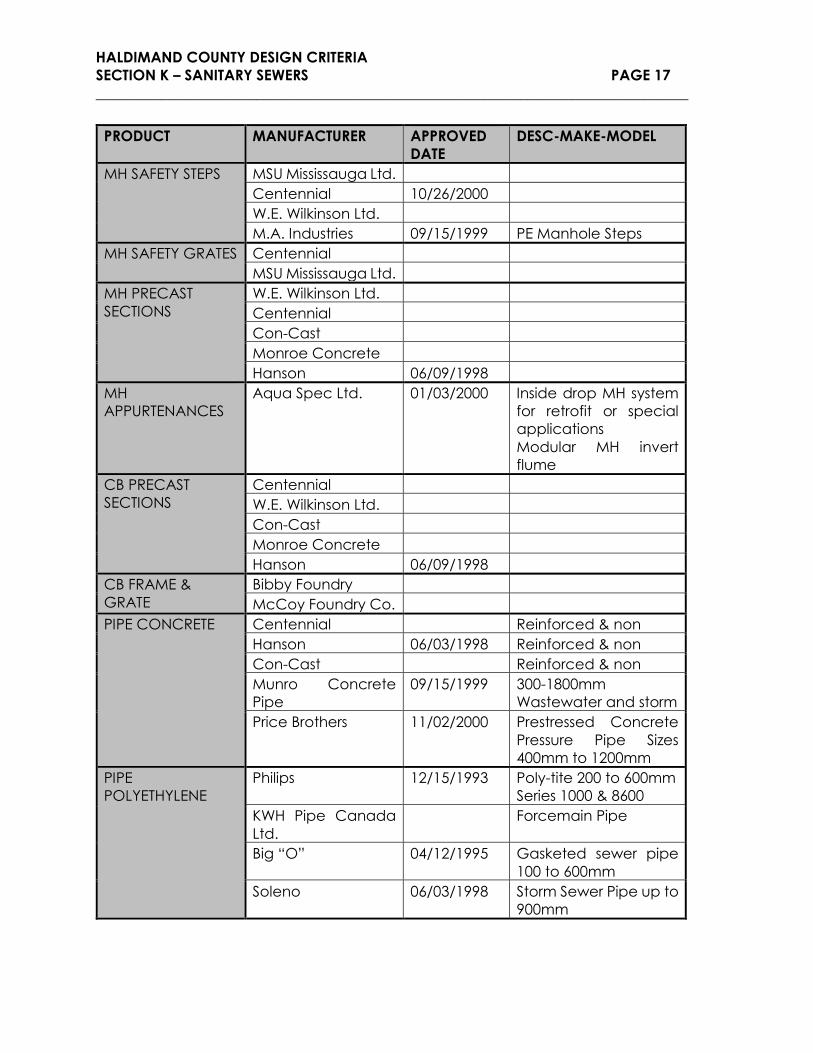
LIST OF APPROVED MANUFACTURERS AND PRODUCTS FOR WASTEWATER SYSTEMS
PRODUCT MANUFACTURER APPROVED
DATE
DESC-MAKE-MODEL
FITTINGS
CONCRETE
Centennial Reinforced and non
Con-Cast Reinforced and non
Hanson 06/09/1998 Reinforced and non
Munro Concrete
Fittings
09/15/1999 300mm to 1800mm
wastewater and storm
FITTINGS PVC Rehau Industries Inc.
Royal Flex-lox Pipe 06/13/1990
IPEX
Le Ron Plastics 06/12/1996 Gasketed and ribbed
fittings
Plastic Trend 08/14/1996 Plastic Trend Sewer
Fittings 150 and 200mm
Preper 08/18/1997 Rubber Coupling for
Sewer Pipe
Mission 09/15/1999 Rubber Adjustable
Sewer Repair
Couplings
FITTINGS VC Logan Vitrified Clay
FITTINGS
POLYETHELYNE
KWH Pipe Canada
Ltd.
Ken Taylor Ind. 06/09/1998 Polyethylene
Adjustment Shims
CASTINGS Domestic Foundry
Ltd.
04/17/1991 Municipal Castings All
Models except #DF307
MH ADJUSTERS Brooklin Concrete 11/04/1992 Multi-Loc adj ring
Centennial Bricking & Precast
Turner Co. 11/04/1992 Rubber MH riser ring
W.E. Wilkinson Ltd. Bricking & Precast
Domal Envirotech Rubber Riser Rings
Hanson 06/09/1998 Precast
IPEX 11/02/2000 Lifesaver Manhole
Adjustment Ring 24”
and 27” dia.
MH FRAME AND
COVER
Bibby Foundry
Mueller 06/11/2013 The Adjustable
McCoy Foundry 04/12/1995 OPSD 401.01
HALDIMAND COUNTY DESIGN CRITERIA
SECTION K – SANITARY SEWERS PAGE 17
_________________________________________________________________________________
PRODUCT MANUFACTURER APPROVED
DATE
DESC-MAKE-MODEL
MH SAFETY STEPS MSU Mississauga Ltd.
Centennial 10/26/2000
W.E. Wilkinson Ltd.
M.A. Industries 09/15/1999 PE Manhole Steps
MH SAFETY GRATES Centennial
MSU Mississauga Ltd.
MH PRECAST
SECTIONS
W.E. Wilkinson Ltd.
Centennial
Con-Cast
Monroe Concrete
Hanson 06/09/1998
MH
APPURTENANCES
Aqua Spec Ltd. 01/03/2000 Inside drop MH system
for retrofit or special
applications
Modular MH invert
flume
CB PRECAST
SECTIONS
Centennial
W.E. Wilkinson Ltd.
Con-Cast
Monroe Concrete
Hanson 06/09/1998
CB FRAME &
GRATE
Bibby Foundry
McCoy Foundry Co.
PIPE CONCRETE Centennial Reinforced & non
Hanson 06/03/1998 Reinforced & non
Con-Cast Reinforced & non
Munro Concrete
Pipe
09/15/1999 300-1800mm
Wastewater and storm
Price Brothers 11/02/2000 Prestressed Concrete
Pressure Pipe Sizes
400mm to 1200mm
PIPE
POLYETHYLENE
Philips 12/15/1993 Poly-tite 200 to 600mm
Series 1000 & 8600
KWH Pipe Canada
Ltd.
Forcemain Pipe
Big “O” 04/12/1995 Gasketed sewer pipe
100 to 600mm
Soleno 06/03/1998 Storm Sewer Pipe up to
900mm

HALDIMAND COUNTY DESIGN CRITERIA
SECTION K – SANITARY SEWERS PAGE 18
_________________________________________________________________________________
PRODUCT MANUFACTURER APPROVED
DATE
DESC-MAKE-MODEL
PIPE VC
SADDLES
Logan Vitrified Clay
Clow Canada Ltd. D-50 125mm & 150mm
Crowle Fittings Cast Iron Saddles
Mission 09/15/1999 Rubber Flexible
Saddles
SEALENTS Presfab Inc. Ring-O-Pave Safe
Match
Rehau Industries Inc. Bond-Loc-joint
Centennial 12/12/1990 Kor-N-Seal
COUPLINGS Mission 08/31/2000 Rubber adjustable
sewer repair couplings
Fernco 1980

HALDIMAND COUNTY DESIGN CRITERIA
SECTION K – SANITARY SEWERS PAGE 19
_________________________________________________________________________________
PEAKING FACTORS FOR SANITARY SEWERS
POPULATION M POP. M POP. M POP. M POP. M POP. M
25 4.37 475 3.99 925 3.82 2600 3.50 6200 3.16 9800 2.96
50 4.31 500 3.97 950 3.81 2800 3.47 6400 3.14 10000 2.95
75 4.28 525 3.96 975 3.81 3000 3.44 6600 3.13 10200 2.95
100 4.24 550 3.95 1000 3.80 3200 3.42 6800 3.12 10400 2.94
125 4.22 575 3.94 1050 3.79 3400 3.40 7000 3.11 10600 2.93
150 4.19 600 3.93 1100 3.77 3600 3.37 7200 3.09 10800 2.92
175 4.17 625 3.92 1150 3.76 3800 3.35 7400 3.08 11000 2.91
200 4.15 650 3.91 1200 3.75 4000 3.33 7600 3.07 11200 2.91
225 4.13 675 3.90 1300 3.72 4200 3.31 7800 3.06 11400 2.90
250 4.11 700 3.89 1400 3.70 4400 3.30 8000 3.05 11600 2.89
275 4.09 725 3.89 1500 3.68 4600 3.28 8200 3.04 11800 2.88
300 4.08 750 3.88 1600 3.66 4800 3.26 8400 3.03 12000 2.88
325 4.06 775 3.87 1700 3.64 5000 3.25 8600 3.02 12200 2.87
350 4.05 800 3.86 1800 3.62 5200 3.23 8800 3.01 12400 2.86
375 4.04 825 3.85 1900 3.60 5400 3.21 9000 3.00 12600 2.85
400 4.02 850 3.84 2000 3.59 5600 3.20 9200 2.99 12800 2.85
425 4.01 875 3.84 2200 3.55 5800 3.18 9400 2.98 13000 2.84
450 4.00 900 3.83 2400 3.52 6000 3.17 9600 2.97
HARMON FORMULA M = 1 + (14 / 4+P0.5); 2≤M≤5
M = Ratio of the peak rate of flow to the average rate of flow.
P = Tributary population in thousand

HALDIMAND COUNTY DESIGN CRITERIA
SECTION K – SANITARY SEWERS PAGE 20
_________________________________________________________________________________
FOR PIPE FLOWING FULL
GRADE % 150mm 200mm 250mm 300mm 375mm
V Q V Q V Q V Q V Q
6.00 2.134 .039 2.585 .084 2.999 .152 3.387 .247 3.930 .448
5.00 1.948 .036 2.359 .077 2.738 .139 3.092 .226 3.587 .409
4.00 1.742 .032 2.100 .068 2.449 .124 2.765 .202 3.209 .366
3.50 1.630 .030 1.974 .064 2.291 .116 2.587 .189 3.002 .342
3.00 1.509 .028 1.828 .059 2.121 .108 2.395 .175 2.779 .317
2.50 1.377 .025 1.668 .054 1.936 .098 2.186 .160 2.537 .289
2.00 1.232 .023 1.492 .048 1.732 .088 1.955 .143 2.269 .259
1.80 1.169 .021 1.416 .046 1.643 .083 1.855 .136 2.153 .246
1.60 1.102 .020 1.335 .043 1.549 .079 1.749 .128 2.029 .231
1.50 1.067 .020 1.292 .042 1.500 .076 1.693 .124 1.965 .224
1.40 1.031 .019 1.248 .041 1.449 .073 1.636 .119 1.898 .216
1.30 .993 .018 1.203 .039 1.396 .071 1.579 .115 1.829 .209
1.20 .954 .017 1.156 .038 1.341 .068 1.515 .111 1.758 .200
1.10 .914 .017 1.107 .036 1.284 .065 1.450 .106 1.683 .192
1.00 .871 .016 1.056 .034 1.224 .062 1.383 .101 1.604 .183
0.98 .862 .016 1.045 .034 1.212 .061 1.369 .100 1.588 .181
0.96 .853 .016 1.034 .034 1.200 .061 1.355 .099 1.572 .179
0.94 .844 .015 1.023 .033 1.187 .060 1.341 .098 1.554 .177
0.92 .835 .015 1.012 .033 1.174 .060 1.326 .097 1.539 .176
0.90 .826 .015 1.001 .033 1.162 .059 1.312 .096 1.522 .174
0.88 .817 .015 0.990 .032 1.149 .058 1.297 .095 1.505 .172
0.86 .808 .015 .979 .032 1.135 .058 1.282 .094 1.488 .170
0.84 .798 .015 .967 .031 1.122 .057 1.267 .093 1.470 .168
0.82 .798 .014 .623 .031 1.09 .56 1.252 .091 1.453 .166
Diameters shown in table are nominal. Q & V are base on imperial I.D.s
1m³/s = 1000 liters per second
V = Meter per second
Q = Meter³ per second
n = 0.013
HALDIMAND COUNTY
Velocity & Discharge
For 150mm to 375mm
CIRCULAR PIPE

HALDIMAND COUNTY DESIGN CRITERIA
SECTION K – SANITARY SEWERS PAGE 21
_________________________________________________________________________________
FOR PIPE FLOWING FULL
GRADE %
150mm 200mm 250mm 300mm 375mm
V Q V Q V Q V Q V Q
0.80 0.779 .014 0.944 .031 1.095 .056 1.237 .090 1.435 .164
0.78 0.769 .014 0.932 .030 1.081 .055 1.221 .089 1.417 .162
0.76 0.759 .014 0.920 .030 1.067 .054 1.205 .088 1.399 .160
0.74 0.749 .014 0.908 .030 1.053 .053 1.189 .087 1.380 .157
0.72 0.739 .014 0.895 .029 1.039 .053 1.173 .086 1.361 .155
0.70 0.729 .013 0.883 .029 1.024 .052 1.157 .084 1.342 .153
0.68 0.718 .013 0.870 .028 1.010 .051 1.140 .083 1.323 .151
0.66 0.706 .013 0.857 .028 0.995 .050 1.123 .082 1.303 .149
0.64 0.697 .013 0.844 .027 0.980 .050 1.106 .081 1.284 .146
0.62 0.686 .013 0.831 .027 0.964 .049 1.089 .080 1.263 .144
0.60 0.675 .012 0.817 .027 0.948 .048 1.071 .078 1.243 .142
0.58 0.663 .012 0.804 .026 0.932 .047 1.053 .077 1.222 .139
0.56 0.652 .012 0.790 .026 0.916 .046 1.035 .076 1.201 .137
0.54 0.640 .012 0.775 .025 0.900 .046 1.016 .074 1.179 .134
0.52 0.628 .012 0.761 .025 0.883 .045 0.997 .073 1.157 .132
0.50 0.616 .011 0.746 .024 0.866 .044 0.978 .071 1.135 .129
0.48 0.603 .011 0.731 .024 0.848 .043 0.958 .070 1.112 .127
0.46 0.591 .011 0.716 .023 0.830 .042 0.938 .068 1.088 .124
0.44 0.578 .011 0.700 .023 0.812 .041 0.917 .067 1.064 .121
0.42 0.565 .010 0.684 .022 0.794 .040 0.896 .055 1.040 .119
0.40 0.551 .010 0.667 .022 0.774 0.39 0.874 .064 1.015 .116
0.35 0.515 .009 0.624 .020 0.724 .037 0.818 .060 0.949 .108
0.30 0.477 .009 0.578 .019 0.671 .034 0.757 .055 0.879 .100
0.25 0.436 .008 0.528 .017 0.612 .031 0.691 .050 0.802 .091
0.20 0.390 .007 0.472 .015 0.548 .028 0.618 .045 0.718 .082
Diameters shown in table are nominal. Q & V are based on imperial I.D.s
1m³/s = 1000 liters per second
V = Meter per second
Q = Meter³ per second
n = 0.013
HALDIMAND COUNTY
Velocity and Discharge
for 150mm to 375mm
CIRCULAR PIPE

HALDIMAND COUNTY DESIGN CRITERIA
SECTION K – SANITARY SEWERS PAGE 22
_________________________________________________________________________________
FOR PIPE FLOWING FULL
Grade % 450MM 525MM 600MM 675MM
V Q V Q V Q V Q
6.00 4.438 .729 4.92 1.099 5.38 1.569 5.82 2.148
5.00 4.051 .665 4.49 1.003 4.91 1.432 5.31 1.961
4.00 3.623 .595 4.02 .897 4.39 1.281 4.75 1.754
3.50 3.389 .556 3.76 .839 4.11 1.198 4.44 1.641
3.00 3.138 .515 3.48 .777 3.80 1.109 4.11 1.519
2.50 2.865 .470 3.17 .709 3.47 1.013 3.75 1.387
2.00 2.562 .421 2.84 .635 3.10 .906 3.36 1.240
1.80 2.431 .399 2.69 .602 2.94 .859 3.19 1.177
1.60 2.292 .376 2.54 .568 2.78 .810 3.00 1.109
1.50 2.219 .364 2.46 .550 2.69 .785 2.91 1.074
1.40 2.144 .352 2.38 .531 2.60 .758 2.81 1.038
1.30 2.066 .339 2.29 .512 2.50 .730 2.71 1.000
1.20 1.985 .326 2.20 .491 2.40 .702 2.60 .961
1.10 1.900 .312 2.11 .471 2.30 .672 2.49 .920
1.00 1.812 .298 2.01 .449 2.19 .641 2.37 .877
0.98 1.794 .295 1.99 .444 2.17 .634 2.35 .868
0.96 1.775 .291 1.97 .440 2.15 .628 2.33 .859
0.94 1.757 .289 1.95 .435 2.13 .621 2.30 .850
0.92 1.738 .285 1.93 .430 2.11 .614 2.28 .841
.90 1.719 .282 1.91 .426 2.08 .608 2.25 .832
0.88 1.700 .279 1.88 .421 2.06 .601 2.23 .823
0.86 1.680 .276 1.86 .416 2.04 .594 2.20 .813
0.84 1.661 .273 1.84 .411 2.01 .587 2.18 .804
0.82 1.641 .269 1.82 .406 1.99 .580 2.15 .794
Diameters shown in table are nominal. Q & V are based on imperial I.D.s
1m³/s = 1000 liters per second
V = Meter per second
Q = Meter³ per second
n= 0.013
HALDIMAND COUNTY
Velocity and Discharge
for 450mm to 675mm
CIRCULAR PIPE

HALDIMAND COUNTY DESIGN CRITERIA
SECTION K – SANITARY SEWERS PAGE 23
_________________________________________________________________________________
FOR PIPE FLOWING FULL
GRADE
%
450mm 525mm 600mm 675mm
V Q V Q V Q V Q
0.80 1.620 .266 1.80 .401 1.96 .573 2.12 .784
0.78 1.600 .263 1.77 .396 1.94 .566 2.10 .775
0.76 1.579 .259 1.75 .391 1.91 .558 2.07 .754
0.74 1.559 .256 1.73 .386 1.89 .551 2.04 .749
0.72 1.537 .252 1.70 .381 1.86 .543 2.01 .744
0.70 1.516 .249 1.68 .375 1.84 .536 1.99 .734
0.68 1.494 .245 1.66 .370 1.81 .528 1.96 .723
0.66 1.472 .242 1.63 .364 1.78 .520 1.93 .712
0.64 1.449 .238 1.61 .359 1.76 .512 1.90 .702
0.62 1.427 .234 1.58 .353 1.73 .504 1.87 .691
0.60 1.403 .230 1.56 .348 1.70 .496 1.84 .679
0.58 1.380 .227 1.53 .342 1.67 .488 1.81 .668
0.56 1.356 .223 1.50 .336 1.64 .479 1.78 .656
0.54 1.331 .219 1.48 .330 1.61 .471 1.74 .644
0.52 1.306 .214 1.45 .324 1.58 .462 1.71 .632
0.50 1.281 .210 1.42 .317 1.55 .453 1.68 .620
0.48 1.255 .206 1.39 .311 1.52 .444 1.64 .608
0.46 1.229 .202 1.36 .304 1.49 .434 1.61 .595
0.44 1.202 .197 1.33 .298 1.46 .425 1.57 .582
0.42 1.174 .193 1.30 .291 1.42 .415 1.54 .568
0.40 1.146 .188 1.27 .284 1.39 .405 1.50 .555
0.35 1.072 .176 1.19 .265 1.30 .379 1.41 .519
0.30 0.992 .163 1.10 .246 1.20 .351 1.30 .480
0.25 0.906 .149 1.00 .224 1.10 .320 1.19 .439
0.20 0.810 .133 0.90 .201 0.98 .286 1.06 .392
Diameters shown in table are nominal. Q & V are based on imperial I.D.s
1m³/s = 1000 liters per second
V = Meter per second
Q = Meter³ per second
n = 0.013
HALDIMAND COUNTY
Velocity and Discharge
for 450mm to 675mm
CIRCULAR PIPE

HALDIMAND COUNTY DESIGN CRITERIA
SECTION K – SANITARY SEWERS PAGE 24
_________________________________________________________________________________
FOR PIPE FLOWING FULL
GRADE % 750MM 825MM 900MM 975MM
V Q V Q V Q V Q
6.00 6.24 2.845 6.65 3.665 7.05 4.626 7.43 5.727
5.00 5.69 2.597 6.07 3.349 6.43 4.223 6.78 5.228
4.00 5.09 2.323 5.43 2.995 5.75 3.777 6.07 4.676
3.50 4.77 2.173 5.08 2.802 5.38 3.533 5.68 4.374
3.00 4.41 2.012 4.70 2.594 4.98 3.271 5.25 4.050
2.50 4.03 1.836 4.29 2.368 4.55 2.986 4.80 3.697
2.00 3.60 1.643 3.84 2.118 4.07 2.671 4.29 3.306
1.80 3.42 1.558 3.64 2.009 3.86 2.534 4.07 3.137
1.60 3.22 1.469 3.43 1.894 3.64 2.389 3.84 2.957
1.50 3.12 1.422 3.32 1.834 3.52 2.313 3.72 2.863
1.40 3.01 1.374 3.21 1.772 3.40 2.235 3.59 2.766
1.30 2.90 1.324 3.09 1.707 3.28 2.153 3.46 2.666
1.20 2.79 1.272 2.97 1.640 3.15 2.069 3.32 2.561
1.10 2.67 1.218 2.85 1.571 3.02 1.981 3.18 2.452
1.00 2.55 1.161 2.71 1.498 2.88 1.889 3.03 2.338
0.98 2.52 1.150 2.69 1.482 2.85 1.870 3.00 2.315
0.96 2.50 1.138 2.66 1.467 2.82 1.850 2.97 2.291
0.94 2.47 1.126 2.63 1.452 2.79 1.831 2.94 2.267
0.92 2.44 1.114 2.60 1.436 2.76 1.811 2.981 2.243
0.90 2.42 1.102 2.57 1.421 2.73 1.792 2.88 2.218
0.88 2.39 1.090 2.55 1.405 2.70 1.772 2.84 2.193
0.86 2.36 1.077 2.52 1.389 2.67 1.751 2.81 2.168
0.84 2.33 1.064 2.49 1.372 2.64 1.731 2.78 2.143
0.82 2.31 1.052 2.46 1.356 2.60 1.710 2.75 2.117
Diameters shown in table are nominal. Q & V are based on imperial I.D.s
1m³/s = 1000 liters per second
V = Meter per second
Q = Meter³ per second
n = 0.013
HALDIMAND COUNTY
Velocity and Discharge
for 750mm to 975mm
CIRCULAR PIPE

HALDIMAND COUNTY DESIGN CRITERIA
SECTION K – SANITARY SEWERS PAGE 25
_________________________________________________________________________________
FOR PIPE FLOWING FULL
GRADE % 750mm 825mm 900mm 975mm
V Q V Q V Q V Q
0.80 2.28 1.039 2.43 1.339 2.57 1.689 2.71 2.091
0.78 2.25 1.026 2.40 1.323 2.54 1.668 2.68 2.065
0.76 2.22 1.013 2.37 1.306 2.51 1.646 2.64 2.038
0.74 2.19 .999 2.33 1.288 2.47 1.625 2.61 2.011
0.72 2.16 .986 2.30 1.271 2.44 1.603 2.57 1.983
0.70 2.13 .972 2.27 1.253 2.41 1.580 2.54 1.956
0.68 2.10 .958 2.24 1.234 2.37 1.557 2.50 1.928
0.66 2.07 .944 2.20 1.217 2.34 1.534 2.46 1.899
0.64 2.04 .929 2.17 1.198 2.30 1.511 2.43 1.870
0.62 2.01 .915 2.14 1.179 2.26 1.487 2.39 1.841
0.58 1.94 .885 2.07 1.140 2.19 1.438 2.31 1.781
0.56 1.91 .869 2.03 1.121 2.15 1.413 2.27 1.750
0.54 1.87 .854 1.99 1.100 2.11 1.388 2.23 1.718
0.52 1.84 .838 1.96 1.080 2.07 1.362 2.19 1.686
0.50 1.80 .821 1.92 1.059 2.03 1.334 2.15 1.653
0.48 1.76 .805 1.88 1.038 1.99 1.308 2.10 1.620
0.46 1.73 .788 1.84 1.016 1.95 1.281 2.06 1.586
0.44 1.69 .770 1.80 .993 1.91 1.253 2.01 1.551
0.42 1.65 .753 1.76 .971 1.86 1.224 1.97 1.515
0.40 1.61 .735 1.72 .947 1.82 1.194 1.92 1.479
0.35 1.51 .687 1.61 .886 1.70 1.117 1.80 1.383
.30 1.39 .636 1.49 .820 1.58 1.034 1.66 1.281
0.25 1.27 .581 1.36 .749 1.44 .944 1.52 1.169
0.20 1.14 .519 1.21 .670 1.29 .845 1.36 1.046
Diameters shown in table are nominal. Q & V are based on imperial I.D.s
1m³/s = 1000 liters per second
V = Meter per second
Q = Meter³ per second
n = 0.013
HALDIMAND COUNTY
Velocity and Discharge
for 750mm to 975mm
CIRCULAR PIPE

HALDIMAND COUNTY DESIGN CRITERIA
SECTION K – SANITARY SEWERS PAGE 26
_________________________________________________________________________________
FOR PIPE FLOWING FULL
GRADE % 1050mm 1200mm 1350mm 1500mm
V Q V Q V Q V Q
6.00 7.81 6.978 8.53 9.963 9.23 13.639 9.90 18.064
5.00 7.13 6.370 7.79 9.095 8.43 12.451 9.04 16.490
4.00 6.37 5.698 6.97 8.135 7.54 11.136 8.09 14.749
3.50 5.96 5.330 6.52 7.609 7.05 10.417 7.54 13.796
3.00 5.50 4.934 6.03 7.045 6.53 9.644 7.00 12.773
2.50 5.02 4.504 5.51 6.431 5.96 8.804 6.39 11.660
2.00 4.49 4.029 4.93 5.752 5.33 7.875 5.72 10.429
1.80 4.26 3.822 4.67 5.457 5.06 7.471 5.42 9.894
1.60 4.02 3.604 4.41 5.145 4.77 7.043 5.11 9.328
1.50 3.89 3.489 4.27 4.981 4.62 6.820 4.95 9.032
1.40 3.76 3.371 4.12 4.813 4.46 6.588 4.78 8.726
1.30 3.62 3.248 3.97 4.637 4.30 6.349 4.61 8.408
1.20 3.48 3.121 3.82 4.456 4.13 6.100 4.43 8.078
1.10 3.33 2.988 3.65 4.266 3.95 5.840 4.24 7.735
1.00 3.18 2.849 3.48 4.057 3.77 5.568 4.04 7.375
0.98 3.15 2.820 3.45 4.026 3.73 5.512 4.00 7.300
0.96 3.11 2.791 3.41 3.985 3.69 5.456 3.96 7.226
0.94 3.08 2.762 3.38 3.943 3.65 5.399 3.92 7.150
0.92 3.05 2.732 3.34 3.901 3.61 5.341 3.88 7.073
0.90 3.02 2.703 3.31 3.859 3.58 5.283 3.84 6.996
0.88 2.98 2.672 3.27 3.815 3.54 5.224 3.79 6.918
0.86 2.95 2.642 3.23 3.772 3.50 5.164 3.75 6.839
0.84 2.91 2.611 3.19 3.728 3.45 5.103 3.71 6.759
0.82 2.89 2.580 3.15 3.683 3.41 5.042 3.66 6.678
Diameters shown in table are nominal. Q & V are based on imperial I.D.s
1m³/s = 1000 liters per second
V = Meter per second
Q = Meter³ per second
n = 0.013
HALDIMAND COUNTY
Velocity and Discharge
for 1050mm to 1500mm
CIRCULAR PIPE

HALDIMAND COUNTY DESIGN CRITERIA
SECTION K – SANITARY SEWERS PAGE 27
_________________________________________________________________________________
FOR PIPE FLOWING FULL
GRADE % 1050mm 1200mm 1350mm 1500mm
V Q V Q V Q V Q
0.80 2.85 2.548 3.12 3.638 3.37 4.980 3.62 6.596
0.78 2.81 2.516 3.08 3.592 3.33 4.918 3.57 6.513
0.76 2.78 2.484 3.04 3.546 3.29 4.854 3.52 6.429
0.74 2.74 2.451 3.00 3.499 3.24 4.790 3.48 6.344
0.72 2.70 2.417 2.96 3.451 3.20 4.725 3.43 6.258
0.70 2.67 2.383 2.91 3.403 3.15 4.659 3.38 6.170
0.68 2.63 2.349 2.87 3.354 3.11 4.592 3.33 6.081
0.66 2.59 2.314 2.83 3.304 3.06 4.524 3.28 5.991
0.64 2.55 2.279 2.79 3.254 3.01 4.455 3.23 5.900
0.62 2.51 2.243 2.74 3.203 2.97 4.384 3.18 5.807
0.60 2.47 2.207 2.70 3.151 2.92 4.313 3.13 5.712
0.58 2.43 2.170 2.65 3.098 2.87 4.241 3.08 5.616
0.56 2.39 2.32 2.61 3.044 2.82 4.167 3.03 5.519
0.54 2.34 2.093 2.56 2.989 2.77 4.092 2.97 5.419
0.52 2.30 2.054 2.51 2.933 2.72 4.015 2.92 5.318
0.50 2.25 2.014 2.46 2.876 2.66 3.937 2.86 5.215
0.48 2.20 1.974 2.41 2.818 2.61 3.858 2.80 5.109
0.46 2.16 1.932 2.36 2.759 2.56 2.777 2.74 5.002
0.44 2.11 1.890 2.31 2.698 2.50 3.694 2.68 4.892
0.42 2.07 1.846 2.26 2.636 2.44 3.609 2.62 4.779
0.40 2.02 1.802 2.20 2.572 2.38 3.522 2.56 4.664
0.35 1.89 1.685 2.06 2.406 2.23 3.294 2.39 4.363
0.30 1.75 1.560 1.91 2.228 2.06 3.050 2.21 4.039
0.25 1.59 1.424 1.74 2.034 1.88 2.784 2.02 3.687
0.20 1.43 1.274 1.56 1.819 1.69 2.490 1.81 3.298
Diameters shown in table are nominal. Q & V are based on imperial I.D.s
1m³/s = 1000 liters per second
V = Meter per second
Q = Meter³ per second
n = 0.013
HALDIMAND COUNTY
Velocity and Discharge
for 1050mm to 1500mm
CIRCULAR PIPE

HALDIMAND COUNTY DESIGN CRITERIA
SECTION K – SANITARY SEWERS PAGE 28
_________________________________________________________________________________
FOR PIPE FLOWING FULL
GRADE % 1650mm 1800mm 1950mm
V Q V Q V Q
6.00 10.55 23.291 11.18 29.374 11.795 36.362
5.00 9.63 21.262 10.21 26.814 10.768 33.196
4.00 8.62 19.017 9.13 23.984 9.631 29.691
3.50 8.06 17.789 8.54 22.435 9.009 27.773
3.00 7.46 16.469 7.91 20.770 8.341 25.714
2.50 6.81 15.034 7.22 18.961 7.614 23.473
2.00 6.09 13.447 6.46 16.959 6.810 20.994
1.80 5.78 12.757 6.13 16.089 6.461 19.918
1.60 5.45 12.028 5.78 15.169 6.091 18.777
1.50 5.28 11.646 5.59 14.687 5.898 18.182
1.40 5.10 11.251 5.40 14.189 5.698 17.566
1.30 4.91 10.841 5.21 13.673 5.490 16.925
1.20 4.72 10.416 5.00 13.138 5.275 16.262
1.10 4.52 9.973 4.79 12.577 5.050 15.568
1.00 4.30 9.509 4.57 11.992 4.815 14.844
0.98 4.26 9.413 4.52 11.871 4.767 14.696
0.96 4.22 9.316 4.47 11.750 4.718 14.545
0.94 4.18 9.219 4.43 11.627 4.669 14.394
0.92 4.13 9.120 4.38 11.502 4.619 14.240
0.90 4.09 9.021 4.33 11.377 4.568 14.082
0.88 4.04 8.920 4.28 11.249 4.517 13.925
0.86 4.00 8.818 4.23 11.121 4.466 13.768
0.84 3.95 8.715 4.18 10.991 4.413 13.604
0.82 3.90 8.610 4.13 10.859 4.361 13.444
Diameters shown in table are nominal. Q & V are based on imperial I.D.s
1m³/s = 1000 liters per second
V = Meter per second
Q = Meter³ per second
n = 0.013
HALDIMAND COUNTY
Velocity and Discharge
for 1650mm to 1950mm
CIRCULAR PIPE

HALDIMAND COUNTY DESIGN CRITERIA
SECTION K – SANITARY SEWERS PAGE 29
_________________________________________________________________________________
FOR PIPE FLOWING FULL
GRADE % 1650mm 1800mm 1950mm
V Q V Q V Q
0.80 3.85 8.505 4.08 10.726 4.307 13.278
0.78 3.80 8.398 4.03 10.591 4.253 13.111
0.76 3.76 8.289 3.98 10.454 4.198 12.942
0.74 3.71 8.180 3.93 10.316 4.142 12.769
0.72 3.66 8.068 3.87 10.175 4.086 12.596
0.70 3.60 7.955 3.82 10.033 4.029 12.421
0.68 3.55 7.841 3.76 9.889 3.971 12.242
0.66 3.50 7.725 3.71 9.742 3.912 12.060
0.64 3.45 7.607 3.65 9.593 3.852 11.875
0.62 3.39 7.487 3.59 9.442 3.792 11.690
0.60 3.34 7.365 3.54 9.289 3.730 11.499
0.58 3.28 7.242 3.48 9.135 3.667 11.305
0.56 3.22 7.116 3.42 8.974 3.604 11.110
0.54 3.17 6.987 3.35 8.912 3.539 10.910
0.52 3.11 6.857 3.29 8.647 3.472 10.704
0.50 3.05 6.724 3.23 8.480 3.405 10.497
0.48 2.98 6.588 3.16 8.308 3.336 10.284
0.46 2.92 6.449 3.10 8.133 3.266 10.069
0.44 2.86 6.307 3.03 7.955 3.194 9.847
0.42 2.79 6.162 2.96 7.772 3.121 9.621
0.40 2.72 6.014 2.89 7.584 3.046 9.390
0.35 2.55 5.625 2.70 7.094 2.849 8.783
0.30 2.36 5.208 2.50 6.568 2.638 8.133
0.25 2.15 4.754 2.28 5.996 2.408 4.723
0.20 1.93 4.252 2.04 5.363 2.154 6.640
Diameters shown in table are nominal. Q & V are based on imperial I.D.s
1m³/s = 1000 liters per second
V = Meter per second
Q = Meter³ per second
n = 0.013
HALDIMAND COUNTY
Velocity and Discharge
for 1650mm to 1950mm
CIRCULAR PIPE

HALDIMAND COUNTY DESIGN CRITERIA
SECTION K – SANITARY SEWERS PAGE 30
_________________________________________________________________________________
FOR PIPE FLOWING FULL
GRADE % 2100mm 2250mm 2400mm
V Q V Q V Q
6.00 12.393 44.309 12.976 53.258 13.547 63.262
5.00 11.313 40.448 11.846 48.620 12.366 57.747
4.00 10.119 36.179 10.595 43.485 11.061 51.653
3.50 9.465 33.841 9.911 40.678 10.346 48.314
3.00 8.763 31.331 9.176 37.661 9.579 44.732
2.50 8.000 28.603 8.376 34.378 8.744 40.833
2.00 7.155 25.582 7.492 30.750 7.821 35.523
1.80 6.788 24.269 7.107 29.170 7.420 34.650
1.60 6.400 22.882 6.701 27.503 6.995 32.665
1.50 6.196 22.153 6.488 26.629 6.773 31.629
1.40 5.986 21.402 6.268 25.726 6.544 30.559
1.30 5.769 20.626 6.040 24.790 6.306 29.448
1.20 5.542 19.815 5.803 23.817 6.058 28.290
1.10 5.306 18.971 5.556 22.804 5.800 27.085
1.00 5.059 18.088 5.298 27.745 5.530 25.824
0.98 5.009 17.909 5.244 21.523 5.475 25.567
0.96 4.957 17.723 5.190 21.302 5.419 25.306
0.94 4.905 17.537 5.136 21.080 5.362 25.040
0.92 4.853 17.351 5.081 20.854 5.305 24.773
0.90 4.800 17.162 5.026 20.628 5.247 24.503
0.88 4.746 16.969 4.970 20.399 5.188 24.227
0.86 4.692 16.775 4.913 20.165 5.129 23.952
0.84 4.637 16.579 4.855 19.927 5.069 23.671
0.82 4.581 16.379 4.797 19.689 5.008 23.386
Diameters shown in table are nominal. Q & V are based on imperial I.D.s
1m³/s = 1000 liters per second
V = Meter per second
Q = Meter³ per second
n = 0.013
HALDIMAND COUNTY
Velocity and Discharge
for 2100mm to 2400mm
CIRCULAR PIPE
HALDIMAND COUNTY DESIGN CRITERIA
SECTION K – SANITARY SEWERS PAGE 31
_________________________________________________________________________________
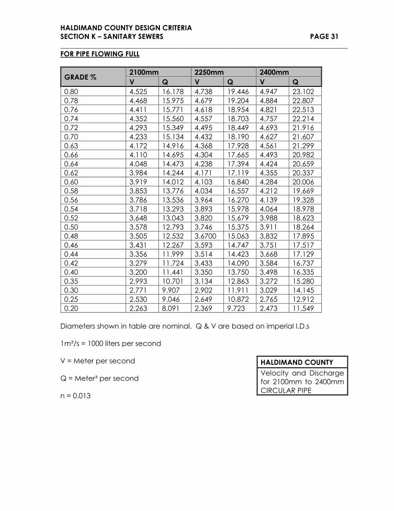
FOR PIPE FLOWING FULL
GRADE % 2100mm 2250mm 2400mm
V Q V Q V Q
0.80 4.525 16.178 4.738 19.446 4.947 23.102
0.78 4.468 15.975 4.679 19.204 4.884 22.807
0.76 4.411 15.771 4.618 18.954 4.821 22.513
0.74 4.352 15.560 4.557 18.703 4.757 22.214
0.72 4.293 15.349 4.495 18.449 4.693 21.916
0.70 4.233 15.134 4.432 18.190 4.627 21.607
0.63 4.172 14.916 4.368 17.928 4.561 21.299
0.66 4.110 14.695 4.304 17.665 4.493 20.982
0.64 4.048 14.473 4.238 17.394 4.424 20.659
0.62 3.984 14.244 4.171 17.119 4.355 20.337
0.60 3.919 14.012 4.103 16.840 4.284 20.006
0.58 3.853 13.776 4.034 16.557 4.212 19.669
0.56 3.786 13.536 3.964 16.270 4.139 19.328
0.54 3.718 13.293 3.893 15.978 4.064 18.978
0.52 3.648 13.043 3.820 15.679 3.988 18.623
0.50 3.578 12.793 3.746 15.375 3.911 18.264
0.48 3.505 12.532 3.6700 15.063 3.832 17.895
0.46 3.431 12.267 3.593 14.747 3.751 17.517
0.44 3.356 11.999 3.514 14.423 3.668 17.129
0.42 3.279 11.724 3.433 14.090 3.584 16.737
0.40 3.200 11.441 3.350 13.750 3.498 16.335
0.35 2.993 10.701 3.134 12.863 3.272 15.280
0.30 2.771 9.907 2.902 11.911 3.029 14.145
0.25 2.530 9.046 2.649 10.872 2.765 12.912
0.20 2.263 8.091 2.369 9.723 2.473 11.549
Diameters shown in table are nominal. Q & V are based on imperial I.D.s
1m³/s = 1000 liters per second
V = Meter per second
Q = Meter³ per second
n = 0.013
HALDIMAND COUNTY
Velocity and Discharge
for 2100mm to 2400mm
CIRCULAR PIPE

HALDIMAND COUNTY DESIGN CRITERIA
SECTION K – SANITARY SEWERS PAGE 32
_________________________________________________________________________________
HALDIMAND COUNTY DESIGN CRITERIA
SECTION K – SANITARY SEWERS PAGE 33
_________________________________________________________________________________