section 8 case studies - bvsde desarrollo sostenible · 8-1 section 8 case studies this section...
TRANSCRIPT
8-1
SECTION 8
CASE STUDIES
This section presents three cases of centralized effluent treatment and three cases ofindustrial waste minimization.
8.1 CASE STUDY 1: CENTRALIZED TREATMENT OF HAZARDOUS WASTE INTHAILAND
This case study was prepared from information in the report Commissioning andOperating an Inorganic Waste Treatment Facility, written by Teerapon Soponkanaporn andAioporn Sophonsridsuk, of the Siam Control Company Limited, Bangkok, Thailand, in 1989.
8.1.1 History of the Facility
In Thailand, hazardous waste is becoming a problem of great concern, especially toxicchemicals and heavy metal pollutants discharged from factories. In fact, heavy-metal-contaminated wastewater is one of the major hazardous wastes in Thailand. The main source ofthese heavy metals is electroplating factories. Presently, approximately 200 medium- andsmall-scale registered electroplating factories are scattered around the Bangkok area.
Treatment of the wastewater at these electroplating factories has not been successfulbecause of a lack of space, trained personnel, financial support, and satisfactory sludgedisposal sites. For these reasons, the Ministry of Industry (MOI) has had difficulty monitoringand controlling hazardous wastes from these electroplating factories.
Recognizing the above problems, the MOI established Thailand's first industrialhazardous waste treatment center in 1988. The center is located in the district of Bangkhuntien,approximately 20 km west of Bangkok. The Bangkhuntien center is the first of four suchindustrial hazardous waste treatment centers that are planned for the western, northern, andeastern suburbs of Bangkok and Rayong. Each center will provide both physical-chemicaltreatment facilities and distillation and incineration for handling industrial liquid, sludge, andsolid hazardous wastes.
8.1.2 Collection
Wastes are collected by tankers (for wastewaters) and trucks (for solid wastes) fortreatment at the Bangkhuntien Industrial Hazardous Waste Treatment Center (BIHWTC). Uponarrival at the BIHWTC, vehicles are weighed and samples of the wastes are taken for ascreening analysis. This analysis determines the nature of the wastes and their compatibility
8-2
with other wastes to be treated. Following analysis, the wastes are discharged into theappropriate sumps for treatment.
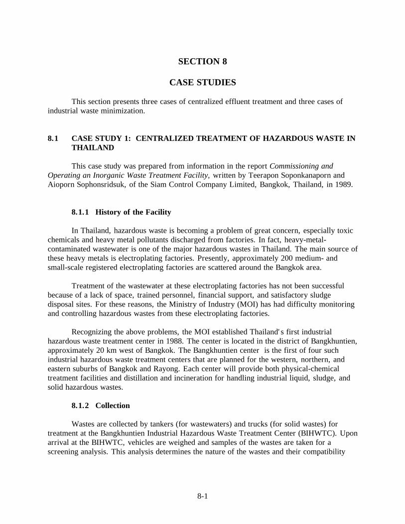
The BIHWTC is designed to treat inorganic wastes such as electroplating wastewatersfrom electroplating factories, spent chemicals such as pickling waste from hot-dip galvanizingand electronic factories, hydroxide sludges from electronic and automobile assembly factories,and mercury wastes from fluorescent lamp manufacturing factories. For more information onthe total number of factories using BIHWTC services and the total quantities of waste, seeFigures 8-1 and 8-2.
Currently, Siam Control Company, Ltd. (SCC), which operates and manages thefacility, is working with the MOI to reduce traffic congestion associated with wastetransportation by adjusting the transportation schedule to transport the waste earlier or later inthe day, thus avoiding peak travel hours. SCC is also considering waste minimization byfactories (e.g., treating wastes with an ion exchange process prior to transport) as a way toreduce the amount of waste being transported, thereby minimizing problems associated withwaste transportation.
8.1.3 Treatment Processes
The BIHWTC includes 1) a 200-cubic-meter-per-day (CMD) chemical treatment plantfor treating electroplating wastewater on a batch basis (see Figure 8-3), 2) an 800-CMDcontinuous chemical flocculation and sedimentation treatment plant and polishing ponds fortreating textile dyeing wastewater, and 3) chemical fixation plus cement mixing facilities forhandling hazardous sludge or solid wastes (see Figure 8-4).
Figure 8-1. Total number of factories using BIHWTC services (Soponkanaporn andSophonsridsuk, 1989)

8-3
Figure 8-2. Total quantity of wastes (ton) (Soponkanaporn and Sophonsridsuk, 1989)
Figure 8-3. Flowchart of electroplating waste treatment (Soponkanaporn andSophonsridsuk, 1989)
Pump Sump
Reactor
Ponds
Water Course
Lab Testing
Drying Bed
To Sludge Disposal
Chemical Agents
Overflow Line
Sludge
Treated Water
Filtrate
Electroplating Wastewater

8-4
Figure 8-4. Plan layout: Bankhuntien Industrial Hazardous Waste Center(Soponkaraporn and Sophonsridsuk, 1989)
8.1.3.1 Electroplating Wastewater
Electroplating wastewaters accepted at the BIHWTC are treated separately according totheir major contaminants (i.e., cyanide, chromium, or other heavy metals).
Cyanide-Contaminated Wastewater
The conventional alkali chlorination process is used to destroy cyanide in theelectroplating wastewater. This process involves using lime to adjust the pH of the wastewaterto between 11.0 and 11.5, then adding sodium hypochlorite (as a chlorine source) andallowing it to react with the wastewater for the desired time. This converts the cyanide togaseous nitrogen and carbon dioxide. During this process, pH and ORP levels areautomatically controlled.
Chromium-Contaminated Wastewater
The toxic hexavalent chromium in the electroplating wastewater is first reduced totrivalent chromium by adding sodium metabisulfite to the wastewater and adjusting the pH to
8-5
between 2.0 and 2.5 using sulfuric acid. Then, lime can be used to precipitate the trivalentchromium at a pH of approximately 10.
Wastewater Contaminated With Other Heavy Metals
Wastewater contaminated with other heavy metals (e.g., nickel, copper, zinc) is treatedusing conventional precipitation with lime at an alkali pH of approximately 10. Polyelectrolytemay be added to improve the setting of hydroxide sludges.
8.1.3.2 Spent Chemicals
Treatment methods for spent chemicals vary depending on the contaminants present inthe wastes. Currently, the only spent chemical that the BIHWTC treats is pickling wastewater,which contains high concentrations of heavy metals. Heavy metals in the pickling wastewaterare precipitated in the same way as those in non-chromium-contaminated electroplatingwastewater. The only difference is that the amount of lime used to treat the picklingwastewaters is considerably higher because of higher concentrations of acid and metal.
Sludge resulting from the chemical treatments is discharged onto drying beds thatcontain a layer of sand. Next, the dried solid wastes are treated using a stabilization processbefore landfilling.
8.1.3.3 Solid Wastes
The hazardous wastes that the BIHWTC currently treats are classified as hydroxidesludges and mercury wastes.
Hydroxide Sludges
Hydroxide sludges contain heavy metals (e.g., lead, manganese, chromium, nickel)other than mercury from various inorganic wastewater treatments. These sludges are mixedwith a high amount of lime to increase the pH to approximately 12 before landfilling.
Mercury Wastes
The mercury in contaminated wastes is stabilized by adding sodium sulphide to convertthe toxic mercury to a more stable mercury sulphide. It is then fixed with cement to form hardblocks before landfilling. Mercury wastes from fluorescent lamp factories are ground beforeinitiating treatment.

8-6
8.1.4 Disposal
After treatment, the effluent is tested for pH, dissolved solids, cyanide, and heavymetals in the center's laboratory to ensure that the effluent meets MOI standards. The effluentthen is discharged to a nearby waterway. Treated sludge is hauled to a disposal site inRatchaburi province approximately 100 km from the center. Extraction tests are performed onthe treated sludge before landfilling to ensure that it will not contaminate ground water withheavy metals.
Development of the landfill site has been costly, exceeding the original MOI budget.As a result, SCC also is looking into recycling heavy metals from electroplating wastewaterand sludges using the "ferrite" process. This process incorporates heavy metals into aferromagnetic precipitate in the presence of an adequate concentration of iron. Part of the ironrequired for the process can be obtained from the pickling wastewater. Because the ferriteprocess (see Figure 8-5) is similar to the present treatment process for inorganic wastes at theBIHWTC, incorporating this new process would require only slight modifications. The ferriteprocess would convert solid wastes into safe and commercially valuable products and wouldtherefore reduce the amount of waste sent to the landfill.
Figure 8-5. Flow chart of heavy metal recovery by ferrite process (Soponkanaporn and Sophonsridsuk, 1989)
Pickling Wastewater
Mixing/Dissolution
Alkalinization
Oxidation
Sedimentation
Neutralization
Effluent
Ferrite Formation
Ferritesludge
Air
NaOH
ElectroplatingWastewater
HydroxideSludge

8-7
8.1.5 Operation and Management
To reduce its burden and continue implementation of its privatization policy, thegovernment awarded the operation and management of the BIHWTC to SCC, a private firm,with a leasing contract for 5 years. SCC has sole responsibility for conducting wastecollection, transportation, treatment, and disposal.
Users pay fees for the following services directly to SCC:
n Transportation from the factories to the BIHWTCn Waste treatmentn Transportation from the BIHWTC to the disposal siten Disposal
These service fees vary depending on the type and volume of waste treated as well asthe distance from the factories to the BIHWTC.
SCC pays rental and royalty fees to the government based on the quantity of wastestreated to offset construction costs for the facility. The government plays only a supervisoryrole. At last count, the government had spent a total of $1.2 million to cover the initial cost ofthe facility, including land acquisition; construction of the center's detoxification facilities forliquid, sludge, and solid hazardous wastes; and installation of necessary equipment andutilities.
8.2 CASE STUDY 2: CENTRALIZED WASTE TREATMENT IN A COMMONEFFLUENT TREATMENT PLANT IN INDIA
This case study was prepared from information contained in a report funded by theWorld Bank entitled India Industrial Pollution Control Project: Feasibility Assessment ofCommon Treatment Facilities, Volume 2.2, Vapi Industrial Estate, prepared by Chemcontrol,Copenhagen, Denmark, 1991.
8.2.1 Case History
In 1960, the Gujarat Industrial Development Corporation (GIDC) established individualindustrial estates throughout Gujarat. Potentially heavy polluting industries (e.g., chemicals,pharmaceuticals) were located within special estates near the coast to prevent inland waterpollution and to provide easy access to national highways and the interstate railway system.Vapi is located in Pardi Taluka in the Bulsar District, about 230 km south of Baroda. Thisindustrial estate currently contains about 1,030 functioning industrial facilities of small andmedium size and more than 3,000 housing units. At present, the main effluent discharge pointis via the Bhi Khadi stream to the Kolak River. Figure 8-6 shows an aerial view of the Vapiindustrial estate.

8-8
The present conditions at Vapi constitute a considerable health hazard for people wholive or work inside the estate. As a result, GIDC has proposed a common effluent treatmentplant (CETP) for industrial effluent and domestic wastewater at a site near the DamangangaRiver. In 1995, the World Bank approved funding for the construction of this facility.
8.2.2 Collection
At present, effluent from various industries flows through open drains to three differentdischarge points at the Vapi estate. GIDC has proposed a common sewer system to carrywastes to the CETP and estimates that the collection and conveyance system and pumpingstations will cost approximately 42.4 million Rs, including the costs of laying sewer pipes andconstructing manholes, etc.
Figure 8-6. Aerial view of the Vapi Industrial Estate (Chemcontrol, 1991)

8-9
8.2.3 Treatment Processes
All industries are required by law to treat their wastewater at least according topretreatment standards, but at present most industries discharge their effluent untreated intosurface drains that ultimately carry the flow away from the estate through three outlets: themajor creek flowing into the Kolak River and the two lesser ones flowing into theDamanganga River. To ensure trouble-free operation of the proposed CETP, however, allindustries will be required to comply with pretreatment standards.
The design of the CETP assumes that industries will comply with the pretreatmentstandards but also acknowledges that full compliance may be unlikely at first. Provisions havebeen built into the design to accommodate minor shockloads of toxic materials, which willinevitably be discharged accidentally with so many industries assembled on one estate.
Incorporating special features to absorb minor shockloads will increase installation costs,however.
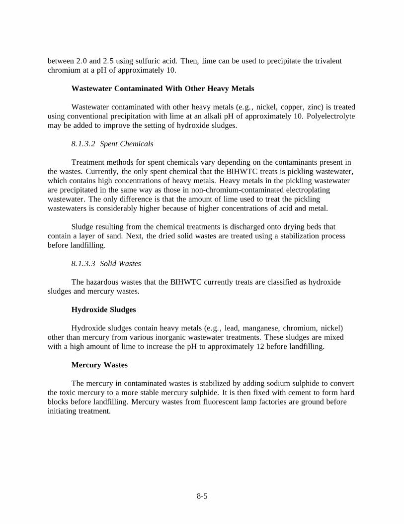
Figure 8-7 illustrates the proposed design of the CETP. This design accounts for spacelimitations and the expected nature of the wastewater influent, and emphasizes cost-effectiveness without compromising the plant's operational safety and reliability. The treatmenttrain for the proposed CETP incorporates the following main processes:
n Pretreatmentn Primary precipitation/primary sedimentationn Equalizationn Activated sludge processn Secondary sedimentationn Sludge concentrationn Lime dosing for stabilizationn Sludge dewateringn Sludge disposal
Each of these elements of the design are discussed below.
8.2.3.1 Pretreatment
Although most wastewater will have been pretreated at the industrial source prior todischarge, the inflow of wastewater to the CETP will contain large fragments (e.g., pieces ofwood, empty bags) that mechanically raked screens will withhold as screenings. In addition,suspended materials in the wastewater influent will include sand and grit which can causeexcessive wear on fast-moving machinery such as pumps and dewatering centrifuges. A gritchamber will be used during pretreatment to separate this sand and grit from the wastewater.
8-10
Figure 8-7. Layout of the Vapi Common Effluent Treatment Plant (Chemcontrol, 1991)
Provision also is made during pretreatment to adjust for low pH in the influent. Allindustries discharging wastewater to the CETP will be required to control the pH of theireffluent to within the range of 5.5 to 9.5. The pH of the influent, however, will probably beon the lower end of what is tolerable for the CETP's biological processes. In addition,ferrosulphate will be added to the water during preliminary precipitation, thus increasing therisk of low pHs. Incorporating lime dosing into the design at the pretreatment stage, however,provides the necessary alkalinity or buffer capacity to withstand any pH drop resulting fromthe ferrosulphate dosage.
8.3.2.2 Primary Precipitation
Although industries discharging to a CETP are required to withhold or remove all toxicmaterials from their effluent, experience indicates that high concentrations of heavy metals willoccur in the wastewater inflow to the CETP, at least during the first 5 to 10 years ofoperation. Excessively high concentrations of heavy metals could hamper the biologicalprocesses (i.e., aeration tanks) of the facility; therefore, the CETP design must provide forefficient removal of heavy metals from the wastewater before it enters the aeration tanks.
Ferrosulphate is dosed as a precipitation agent during primary precipitation to enhancethe efficiency of primary sedimentation which is the next stage of the treatment train. Adding aprecipitation agent such as ferrosulphate, optimizes the withholding of heavy metals in theprimary sedimentation tanks. For this particular facility, ferrosulphate will be dosed as a 25-

8-11
percent solution prepared in the chemical storage building. Dosing will be done in the effluentsfrom the main distribution chamber.
Primary Sedimentation
The main objective of primary sedimentation is to withhold raw sludge from theincoming wastewater in order to reduce the aeration tank volume. Figure 8-8 illustrates aprimary sedimentation tank. If the primary sedimentation tanks are equipped with aflocculation step to enhance primary precipitation (using ferrosulphate), many heavy metals inthe wastewater will be precipitated and withheld in the primary sludge.
Figure 8-8. Primary and secondary sedimentation tank (Chemcontrol, 1991)

8-12
8.2.3.3 Equalization
The purpose of equalization tanks is to not to equalize the flow of influent wastewater,which will have little variation because most industries work continuously, but to equalizepossible pH variations and to dilute unavoidable small shockloads of toxic or inhibitivematerials in wastewater influent. This gives plant operators sufficient time to initiatecountermeasures. Equalization tanks are operated with a constant water level and are keptcompletely mixed by mechanical agitators. The layout for the proposed equalization tanks forthe Vapi facility, are outlined in Figure 8-9.
When a shockload of toxic or inhibitive materials is recognized in the equalizationtanks, activated carbon is immediately dosed into the inlet end of the aeration tanks. Dosingcontinues as long as any toxic materials remain in the tanks.
Activated carbon dosing only takes place in emergency situations. To determine whenthis dosing is necessary, bench-scale activated sludge plants are operated continuously in thelaboratory, fed by effluent from the primary sedimentation tanks. If the respiration rates forthese small plants decrease, then activated carbon is added to the aeration tanks.
8.2.3.4 Activated Sludge Process
The activated sludge process biologically degrades organic matter in wastewater. Theoxygen necessary to sustain the biological processes, such as substrate respiration andnitrification, will be provided by surface aerators that mix air into the mixture of wastewaterand activated sludge in the aeration tanks (see Figure 8-10). To reduce the power demand foraeration, a dissolved oxygen control system regulates the operation of the surface aerators,maintaining a relatively constant concentration of oxygen in the aeration tanks. Dosing ofactivated carbon occurs in the aeration tanks when necessary. Designers selected the activatedsludge process for the CETP because, in combination with activated carbon dosing, it is themost robust biological process for treating industrial wastewater.
An analysis performed on current effluent from the Vapi industrial estate indicates avery low phosphorus content, which could adversely affect the biological growth of activatedsludge in the aeration tanks. This necessitates constant dosing of phosphate to the aerationtanks in the form of a fertilizer with trace substances such as manganese. The fertilizer shouldhave as little nitrogen content as possible because the wastewater already contains a surplus ofnitrogen to sustain the growth of activated sludge.

8-13
Figure 8-9. Equalization tanks (Chemcontrol, 1991)
Figure 8-10. Aeration Tanks (Chemcontrol, 1991)

8-14
8.2.3.5 Secondary Sedimentation
The secondary sedimentation tank is designed to withhold, settle, and concentrate theactivated sludge to such a degree that the effluent from the CETP should be able to meettolerance limits for inland surface waters (biological oxygen demand less than 30 mg/L andsuspended solids less than 100 mg/L) (see Figure 8-8). This only occurs, however, when theoperation of the activated sludge process is trouble free and with only very minor inhibition ofthe biological processes.
Gravity withdraws the sludge settled in the secondary sedimentation tanks into returnsludge pumping stations. Then, screw pumps continuously lift most of the sludge and send itback to the aeration tank inlet as return sludge. Centrifugal pumps will pump excess sludgefrom the wet well to the sludge concentration tanks. The amount of excess sludge the pumpswithdraw each day will be based on maintaining a constant sludge concentration in the aerationtanks.
8.2.3.6 Sludge Concentration
Primary and secondary sludge is concentrated before dewatering to reduce the costs ofelectricity and polymers associated with dewatering. The two sludge types are treateddifferently because they will probably be disposed of in different ways.
Primary sludge is pumped directly from the primary sludge pumping stations to thesludge concentration tank designated for this sludge type. Secondary sludge is pumped fromthe return sludge pumping stations by the excess sludge pumps to the two sludge concentrationtanks designated for this sludge type. An automatic valve arrangement ahead of the twoconcentration tanks ensures that only one tank receives sludge at a time.
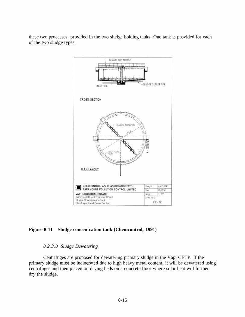
All three sludge concentration tanks are equipped with a continuously operating sludgescraper (see Figure 8-11). Concentrated sludge is withdrawn intermittently during day andnight to secure as high a sludge concentration as possible. Concentrated sludge is dischargedinto sludge sumps, one for each sludge type, then it is pumped to sludge holding tanks.
8.2.3.7 Lime Dosing for Stabilization
Primary sludge is stabilized to prevent the unpleasant odors that emanate from theanaerobic decomposition of sludge. Secondary sludge is fully stabilized because of the longsludge age in the aeration tanks (extended aeration). Lime dosing is used for stabilizingprimary sludge. Lime slurry used for dosing is prepared by mixing lime and water. This isperformed in a chemical storage building, then the slurry is pumped to the sludge well. Oncedosed, the mixture of primary sludge and lime is pumped to the sludge holding tank.
Sludge will be taken out of the sludge concentration tanks around the clock to makeoperation of these tanks as stable and efficient as possible. The mechanical dewatering of thetwo sludge types takes place in two shifts. This necessitates having a buffer capacity between
8-15
these two processes, provided in the two sludge holding tanks. One tank is provided for eachof the two sludge types.
Figure 8-11 Sludge concentration tank (Chemcontrol, 1991)
8.2.3.8 Sludge Dewatering
Centrifuges are proposed for dewatering primary sludge in the Vapi CETP. If theprimary sludge must be incinerated due to high heavy metal content, it will be dewatered usingcentrifuges and then placed on drying beds on a concrete floor where solar heat will furtherdry the sludge.

8-16
Secondary sludge is unsuitable for dewatering on sludge drying beds because the sludgehas such a fine flock structure that water in the middle of the sludge layer is unable to escapeand evaporate. Thus, mechanical dewatering is the only way to reduce the volume ofsecondary sludge before its ultimate disposal.
8.2.3.9 Sludge Disposal
The proposed disposal method for sludge produced at the CETP is for use onagricultural land. This is the least expensive and most environmentally attractive methodprovided the sludge does not contain hazardous components in excessively high quantities orconcentrations. If the primary sludge has an excessively high heavy metal content, it will needto be incinerated. Both primary and secondary sludge will be dewatered to reduce the amountor volume of sludge before disposal. Any sludge suspected of still containing hazardousmaterial will be disposed of in a local controlled landfill.
8.2.4 Operation and Management
The GIDC manages the Vapi industrial estate. Officers of GIDC have suggested thatGIDC also own and manage the CETP. The total project cost for the CETP at Vapi isestimated at 444 million Rs. Annual operating costs are estimated to amount to 54.5 millionRs.

8-17
8.3 CASE STUDY 3: CENTRALIZED TREATMENT IN CETREL S.A.ENVIRONMENTAL PROTECTION COMPANY, PETROCHEMICALCOMPLEX OF CAMAÇARI, BAHÍA, BRAZIL
8.3.1 Case History
The Petrochemical Complex of Camaçari is located in the municipality of Camaçari,state of Bahía, Brazil, and includes several petrochemical industries and other transformationindustries.
Between 1975 and 1976, the project of this industrial area defined centralized treatmentand disposal as the option for all its solid and liquid waste, and this method was implementedin the following years.
CETREL S.A. - Environmental Protection Company deals with hazardous effluents andwastes and provides environmental advisory services to local industries. It has recentlyassumed the control of atmospheric emissions. The public urban cleaning entity is in charge ofthe collection and disposal of non-hazardous solid waste in sanitary landfills.
CETREL was created by the municipal and state governments with a small participationof the private sector. As its technical competence grew, it began to attract the interest ofindustries, which contributed the capital required for the physical and technological expansionof the plant. This reduced State participation in the project. Since 1991, public/privateparticipation has increased to 34.43% and 65.57%, respectively.
At the beginning, there was only one effluent treatment plant responsible for the area'shazardous solid waste, but at present the company operates eight large treatment, disposal, andenvironmental monitoring systems:
• Collection, transportation, treatment, and disposal of effluents• Processing and disposal of non-inert solid waste (class II)• Temporary storage of hazardous solid waste (class I) • Incineration of organochlorine liquid waste• Incineration of hazardous solid waste• Atmospheric monitoring network• Groundwater management• Ocean disposal system (terrestrial and submarine outfalls).
8-18
8.3.2 Operational Units
CETREL has six operational units:
• Effluent treatment station, formed by three aeration tanks, a volatile removalchamber, an equalization tank, twelve secondary basins, three sludge thickeners,two aerobic digesters, 16 “sludge bed” cells and an effluent accumulation tank.
• Incineration area, formed by two incinerators: one for hazardous effluents and theother for hazardous solid waste.
• Solid waste disposal system, formed by various industrial landfill cells, in additionto silos, patios and sheds.
• Groundwater monitoring network, formed by 508 monitoring and production wellsand a hydraulic barrier with 26 wells.
• Ocean disposal system, formed by a “stand-pipe”, a terrestrial outfall (11 km inlength), two balance towers and one submarine outfall (4.8 km).
• Air monitoring network, formed by eight fixed stations that continuously evaluateair quality, an air pollutant remote sensor (FTIR), a telemetry system, an acousticradar and “summa canisters” equipment.
8.3.2 Treatment Processes
8.3.3.1 Effluent Treatment
The industries of the Petrochemical Complex of Camaçari must respect the stateresolution that establishes effluent disposal standards. Furthermore, CETREL complies withanother resolution that establishes standards for sea disposal (through outfalls) of effluentstreated by the company.
The installed capacity of the central effluent treatment plant (ETP) is 144,000 m3/daywith a removal efficiency of 98% of BOD (biochemical oxygen demand) and 86% of COD(chemical oxygen demand).
Effluents are conducted to the ETP through a network of collectors and pumpingstations. With an installed capacity for 120 daily tons of BOD, 360 daily tons of COD, and 54tons of SS (suspended solids), the ETP treats a volume equivalent to the sewerage of a city of3 million inhabitants.
The treatment starts in the VRU (volatile and semivolatile removal unit); then, effluentsare homogenized in the equalization tank, to prevent organic load and flow peaks which affectthe process. Upon passing to the aeration tanks, the liquid mass passes through the activatedsludge, that has an average efficiency of 98% in terms of BOD removal. Once the organicmatter has been degraded, the liquid mass passes to the secondary basins for liquid (effluenttreated) and solid (sludge activated) separation. Part of that sludge continually recycles towardthe aeration tanks; the other part is discarded from the process and passes to the thickeners.

8-19
Then, the biological sludge is stored over a long period, with aeration and without organicmatter, in aerobic digesters, where the microorganisms are significantly reduced because ofself-cannibalism.
8.3.3.2 Hazardous Industrial Waste Treatments
Industrial wastes are classified as hazardous (class I), non-inert (class II), and inert(class III), according to the Brazilian Standard (NBR) 10,004 – Solid Waste Classification, thatspecifies parameters for waste leaching and solubilizing tests. This Brazilian standard is basedon U.S. EPA recommendations.
Processing and final disposal of class II waste is carried out in industrial landfills withcapacity for 80,000 tons/year.
The temporary storage area for hazardous waste consists of silos, patios and sheds.After this area, the waste goes to incineration.
• Industrial Landfill
The mass disposed of in an industrial landfill constitutes a dynamic system, wherebythe contents undergo chemical, physical, and biological alterations. The substances prepared inthe landfill can migrate by liquid or gaseous routes outside the system, provided that there areno waterproof barriers (natural or synthetic). In CETREL, barriers are formed by a well-compacted clay layer overlapped by a high-density polyethylene membrane (HDPE).
This landfill is made up of an isolated chamber (cell) dug in the soil, protected by ahighly waterproof clay layer (coefficient: K<10-7cm/s) and a HDPE membrane to ensure thatthe leachate does not contaminate the ground water table.
Since 1994, CETREL has been using the new landfill construction technology for classII wastes in overlapping layers. This technology makes it possible to form a “vertical landfill”of up to 17 m, in order to maximize land use and reduce the potential soil pollution area.
The new vertical landfill has the capacity to receive 300,000 m3 of waste of up to 17 mhigh with a shelf-life of 60 months. It is subdivided into two sub-cells: the first one, reservedfor waste disposal in drought periods, allows the entry of trucks to the landfill and disposal ofwastes in the work fronts, where they are scattered and compacted by a tractor until reachingthe specified degree of compaction; and the second one, reserved for waste disposal in rainyperiods, allows waste discharge directly from the hoppers to the cell through a launchingplatform.

8-20
• Hazardous Solid Waste Incinerator
The primary function of the incinerator installed in the COPEC is hazardous solidwaste incineration, mainly organochlorine, including PCB. This unit operates 24 hours a dayin three 8-hour shifts. The waste is burned at high temperatures (1,250 o C), with a roughcooling in the post-combustion chamber that inhibits the formation of dioxins anddibenzofurans.
The gas washing system reduces stack emissions to levels lower than those specified bythe legislation.
This solid incinerator, with a capacity for 4,500 tons/year, provides two importantservices:
- it meets the demands of hazardous solid waste generators of the state of Bahía, thusfacilitating compliance with the legislation that prohibits the disposal of that type ofwaste in landfills;
- it serves other state companies, thus making up for the lack of hazardous wasteincinerators at the national level.
• Biological Washing Unit for Contaminated Soil
CETREL developed a washing treatment technique (bio-washing) to reduce soilcontamination from hazardous waste (class I) to non-inert waste (class II), and further disposeof it in an industrial landfill.
The objective of the processing technologies, in liquid phase, for contaminated soilsand hazardous wastes is to obtain aqueous solutions that transport pollutants and degrade themas much as possible or that absorb pollutants in the form of fine particles suspended inbiological sludge or generated solutions.
It should be emphasized that the great advantage of liquid-phase processing ofcontaminated soils, sediments, and wastes is the speed of the physical processes of biologicalreactions comparable to those verified in the activated sludge process.
The processes are based on the following properties and mechanisms:
- Volatile organic compounds are easily dissolved in liquid mass and absorbed in theatmosphere.
- Semivolatile compounds present a high carbon/water absorption coefficient, whichfavors the incorporation of organic substances in the clayey fine particles oractivated sludge. During the washing process, solutions present high concentrationsof organic loads (COD and SS)
- Pollutants are absorbed in fine particles (sediments and clays) and organic carbon,instead of coarse particles (sand and gravel).
8-21
8.3.3.3 Air Monitoring
The air quality analysis of the Petrochemical Complex of Camaçari is carried out basedon a methodology similar to that adopted in the most advanced industrial complexesworldwide, such as that of Bayer in Germany and Lis, in Canada, corresponding to CETRELstandards.
The network's eight fixed stations perform continuous air evaluations (24 hours) in thearea and in neighboring communities. The stations are interconnected through a telemetrysystem, which allows access to fixed stations of the pole. The on-line monitoring of organicpollutant concentrations is carried out through the FTIR–Fourier Transform Infra Red and theSumma Canisters equipment.
8.3.3.4 Groundwater Management
Groundwater monitoring in the area of influence is carried out through a network of508 wells that allow water sample collection for laboratory analysis. A hydraulic barrier wasconstructed to confine the pollutant plume and treat it in the ETP.
The areas that require attention are identified in maps and lithostratigraphs and confinedby a hydraulic barrier that impedes migration of pollutant plumes to other regions.
8.3.4 Disposal of Treated Effluents and Wastes
In effluent treatment, the biological activated sludge treatment eliminates the pollutingorganic load, but generates biosolids as by-products (biological sludge), used as fertilizer andsoil amendment.
The effluents treated in the ETP, with a purification index of approximately 98%, aredisposed of at the bottom of the sea 4.8 kms from the coast, at a depth of 25 m, reaching adilution of 1:400.
The ashes generated in liquid and solid waste incineration, as well as other non-inertwastes, are disposed of in the sanitary landfill.
8.3.5 Client Service
CETREL classifies its clients in two groups, according to the contractual relationship:permanent or for a specific length of time.
Criteria for client classification

8-22
G1 Companies interconnected to the CETREL integrated systems orwhich use those systems on an ongoing basis.
G2 Companies that contract CETREL services for a specific length oftime.
Present or potential needs of the clients are classified in two main categories:
- environmental requirements: effective delivery of effluent and industrial wastetreatment and disposal services, and environmental monitoring services(enforcement authorities);
- expectations with regard to services: attributes that the client expects from itsrelationship with CETREL, such as punctuality, good attention, promptness,market prices and speed, among others.
To identify specific needs of each client, mechanisms that can vary according to theircharacteristics:
- Contractual control: all environmental protection services offered have specificprocedures. For G1 companies, mainly COPEC industries, an attendance process isfollowed to assess and guarantee compliance with environmental requirements. Incase of G2 clients, CETREL prepares a specific specification for each contract.
- Attendance meetings: technical meetings are held to exchange opinions between G1and G2 clients regarding their expectations of the service quality level.
- Opinion polls: starting in 1997 a specific and periodic research methodology wasimplemented for G1 and G2 clients, where the degree of satisfaction wasmeasured.
- Visit to potential clients: the Client Service Group establishes an action plan forpotential client visits, based on consultations with publications of state industrialfederations and state environmental control entities, as well as their respectivelegislation.
- Legislation study: the main requirement of G1 clients is to treat their industrialeffluents and wastes according to legal standards to prevent a significantenvironmental impact.

8-23
Figure 8-12. Integration of environmental protection systems of CETREL
INCINERATIONAREA
Effluent collectionrecolecciónand transportation
networkETP Sea
Terrestrialsubmarine
outfall
EFFLUENTPROCESSING
Sampling andoceanogr. analysis
Recycling foragriculturalpurposes
Groundwatermonitoring
Gas washingSystem and airmonitoring
network
Solidincinerator
Liquidincinerator
SOLID WASTEPROCESSING
Silos, patios andsheds
(Class I)
Industriallandfills(Class I)
Atmospheric emissions
Ashes
Ashes
Effluents
Effluents
Biosolids
Leac
hate

8-24
Figure 8-13. Client service flow diagram of CETREL
The client checks
with CETREL
CETREL gives the userthe Simplifiedeffluent/waste
register
The client returns the filled-outregister
CETREL evaluates theregister
Additional treatmenttests arerequired?
CETREL carries outtests
NO
YES
¿Effluents/wastes comply with
standards?
NO¿A special permitcan be granted?
NORecommend
other treatment
YES
Acceptance ofeffluents/wastes
The client signs a contractwith CETREL

8-25
8.4 CASE STUDY 4: RATIONAL USE OF WATER IN INDUSTRIAL DRYCLEANING. CASE STUDY IN A SELECTED DRY-CLEANING PLANT INBUENOS AIRES, ARGENTINA (1997 - 1998).
8.4.1 Case History
The textile industry is an activity that demands high water consumption and generates acorrespondingly large volume of sewerage. It is classified within the ten most pollutantactivities. The complex situation experienced by the sector, together with the strong legalpressure and the high cost of water in the metropolitan area (US$ 0.25/m3) makesimprovements necessary in the different aspects of the process:
§ rationalization of water use§ recycling of scouring and cooling liquids§ use of dry cleaning equipment§ optimization of dyeing techniques§ removal or substitution of polluting products.
8.4.2 Objective
To evaluate dry-cleaning processes and study the possibility of recovering the waterused at different stages of the process.
8.4.3 Project Development
From the water-saving perspective, it is interesting to note that according to the surveyconducted by the Centro de Investigación Tecnológica of Argentina (CIT), an average waterconsumption of 0.24 m3//kg of finished product was registered for the print shops and dry-cleaning category. As reference, an industrialized European country uses 0.14 m3/kg andutilizes equipment similar to that currently used in Argentina.
Most large-scale enterprises have implemented, or are in the process of implementing,purification systems for their discharges. Small and medium-scale industries cannot treat theireffluents because of economic problems or lack of space. Although projects have beenimplemented for industrial discharge treatment in a common plant, they have not beensuccessful.
Although most modern treatment technologies have been implemented in Argentina,SMSEs always consider associated costs to be very burdensome. Therefore, minimization isnot only a logical and available tool, but a sound, essential and completely attainable elementto face costs generated by industrial production.

8-26
If the purpose is exclusively to recover waters from dry-cleaning processescorresponding to:
§ second rinse§ second rinse of the scouring§ softening of color tissues and washings (cationic basis) and§ softening of optic and melange white (silicone basis)
the total volume of water recovered annually will reach l38,200 m3.
The intention is not to carry out a detailed analysis at this stage, i.e. not to considerpossible savings in raw materials dissolved in waters to be recovered (detergents, soda, aceticacid, softeners, etc.) nor those associated with not treating approximately 130 m3of sewerageper day. Nevertheless, it would be necessary to analyze the degree of saving in terms ofexploitation and effluent of waters that can be recycled or, in other words, the tax paid toAguas Argentinas for the use of water and sewerage.
8.4.4 Conclusions
According to present rates, Aguas Argentinas charges $Arg 0.5478/m3 for the “use ofwater and collector”, and therefore, the savings achieved by recycling the water used in dry-cleaning, would amount to approximately $ Arg 21,000/year, a significant figure if oneconsiders that it usually simply "goes down the drain" -- literally -- with no comparativeadvantage.
This work, carried out in an SMSE, demonstrates that recovering waters from textilescouring and softening, saves approximately 22% of total water consumption.
Saving not only favors cost reduction, but also makes the sector's companies morecompetitive, which in turn, facilitates final disposal.

8-27
8.5 CASE STUDY 5: APPLICATION OF THE WASTE MINIMIZATIONPRINCIPLE IN A TANNERY
8.5.1 Case History
The case study for applying the minimization principle in this industrial sector wasperformed by CEPIS in a tannery in Lima, Peru with GTZ support. The tannery has two mainproduction lines: caprine and ovine hide. Of an average number of 28,000 hides processedmonthly, 18,000 (65% of production) are caprine hides, and the remaining 10,000 are sheephides. The production line of caprine hides was selected because of its low fat content, whichfacilitates reuse of hairing baths.
8.5.2 Objective
The case study was carried out (a) to evaluate recovery of effluents from the hairingand tanning processes; (b) to determine the optimal design parameters of the recovery systemsin this sector and (c) to develop some proposals for the rational use of water and chemicals andplant cleaning.
8.5.3 Development of the Case Study
The characterization of hairing and tanning effluents showed high concentrations ofsulfides and chromium. The values served as indicators to establish possible effluent reuse.
According to the literature, reuse of hairing baths is not very common because of thehigh fat content. In view of the fact that caprine hide is less fatty, reuse was considered atechnically and economically feasible technique for this type of hide. Three evaluations werecarried out on a semi-industrial scale to assess this hypothesis, as well as to determine the bestreuse technique for the discharged effluent.
In addition to the routine analysis to determine sulfide concentration in the bathrecovered, basic parameters were analyzed for variations due to reuse. It was concluded thatthe concentration of the polluting load increases considerably as well as the concentration ofsolids, which reduces the final effluent volume and hence, final treatment costs.
Reuse of the Tanning Bath
Although the volume of the tanning bath is small in comparison to that of the hairingbath, it is important to study techniques for its recovery and further reuse since the content ofCr+3 can reach toxic levels. Furthermore, the saving of this chemical implies a significanteconomic benefit for the industry.

8-28
On average, 25% was saved in all process chemicals, 55% of the bath volume wasrecovered for reuse, and the total required was completed with pickling bath. This means that100% of the water volume was recovered through reuse.
8.5.3.1 Hairing and Tanning Bath Recovery System
A system was designed for the recovery, treatment, and storage of reuse baths (hairingand tanning baths). In addition, other measures were proposed regarding the rational use ofwater and chemicals, as well as industrial plant cleaning.
8.5.3.2 Economic Evaluation
The profitability of the hairing and tanning bath reuse proposals was evaluated. Theindicators were internal rate of return (IRR), net present value of investments (NPV) andreturn period.
The evaluation shows that the project is economically profitable for the reuse of bothhairing and tanning baths. The results were a net present value of US$ 34,581, an internal rateof return of 30% and a return period of three years and seven months.
Planned Income
With the case study results, comparisons were made to determine chemical and watersavings that would be obtained when implementing the proposals for reuse of hairing andtanning solutions. The evaluation showed an annual saving of US$ 13,400 for a production of18,000 caprine hides per month. An average weight of 1.15 kg was considered for a mediumcaprine hide to obtain the equivalent consumption.
In the case of reuse of the hairing baths of 500 medium caprine hides, a maximum offour reuses were obtained without altering the product quality; the total weight of theprocessed hides was 509.5 kg. In tanning, the processing of 1,770 medium hides (1,870 kg ofhide) was tested with 15 reuses.

8-29
8.6 CASE STUDY 6: APPLICATION OF THE WASTE MINIMIZATIONPRINCIPLE IN A TEXTILE INDUSTRY
8.6.1 Introduction
For the implementation of the CEPIS/GTZ case study (1993), the cotton sector wasconsidered the most productive in the countries of Latin America.
The textile industry of the case study produces on average 260 tons per month:corduroy, drill, poplin, flannel, cretonne, plush, adhesive tape cloth, calico, polyester, andsandpaper.
8.6.2 Objectives
The objectives of this project were:
• To identify and characterize wastes• To evaluate chemical recovery methodologies in the laboratory• To evaluate and verify input recovery and recycling techniques on a semi-industrial
scale• To plan and develop modifications on an industrial scale• To carry out the economic evaluation at the industrial level.
8.6.3 Development of the Case Study
To initiate the study, the industrial productive process was reviewed. The processes aredry or wet according to generation of effluent. Both spinning and weaving are dry processes,while the others are wet.
8.6.3.1 Characteristics of Global Effluent
In general, the COD value was 120 to 2,000 mg/L, which is a value expected in thistype of wa0ste (strong concentration). The COD and BOD5 have a ratio of 7.5 to 15.0; in thiscase BOD5 concentration ranged from 50 to 200 mg/L. The pH of 9.5 on average, consideredhigh despite the sodium hydroxide recovery, indicated that the water was strongly alkaline.The temperature exceeded the permissible values for discharge in sewerage and receivingstreams despite the fact that two heat exchangers had been installed, not for the purpose oflowering the effluent temperature but to pre-heat the water that feeds additional operations. Itshould be indicated that all wastes contained a large quantity of dyes, which are significantlypollutant from the aesthetic and probably toxic point of view.
8-30
8.6.3.2 Minimization Strategies
When initiating the case study, the industry confirmed to have some minimizationalternatives implemented.
- Minimization Strategies Developed by the Industry before the Case Study
Reuse of the Mercerizing Bath
The sodium hydroxide bath is stored in two tanks of 11 m3 capacity. After eliminatingthe impurities through a revolving filter, it is reused in another mercerizing process. The sodaconcentration is measured and is titrated with sulfuric acid (H2SO4) to complement the dosage.
Reuse of the Sizing Solution
After using the rubber in a process, it is stored in the pad tray and discarded once itgets dirty or when its concentration is reduced.
Reuse of Dyes in Thermosol
Only dyes used in Thermosol are recovered except reagents that are decomposed.
Reuse of Scouring and Bleaching Baths
The baths remaining from these processes are reused; the product concentration isdetermined and the concentration is completed when required. After a process, the scouring orbleaching bath is pumped to the tank which has a capacity of 1,500 L.
Recirculation of Industrial Wastewater, Plaid and Rotary Print Machine
The shower water that washes the rubber belt is reused using a closed circuit,previously filtered by strainers.
Recirculation of Cooling Waters in the Pre-shrunk and Tumbler Dryer
The cooling water of the rubber belt is recycled in closed circuit for the pre-shrunkmachine, previously filtered before it goes to the tumbler dryer.
Effluent from the Mercerizing and Washing Machine
To recover heat, the effluent passes through an Alpha-laval heat exchanger, input flowis pre-heated and the effluent temperature is lowered, which requires less steam for heating.This represents a significant fuel saving for the enterprise. The Alpha-laval has been adaptedwith filters to eliminate impurities that might obstruct the equipment.

8-31
8.6.3.3 Minimization Proposals for the Case Study
Considering the processes developed in this company for cloth manufacturing and themeasures applied, it is estimated that the company has already initiated the waste minimizationstrategy.
To determine the activities to be developed in the case study, CEPIS had to evaluate thefollowing proposals:
a. Change of faucets in the areas of:- washing of tables and equipment in the calico section- washing of the Thermosol machine.
The use of pressure faucets was recommended (regulating handgun type) which areused by the operator to handle the water flow easily and reduce water consumption.
b. Water recovery in the overflow of the plaid print machine, which required greaterstorage to facilitate its recovery.
c. Recovery of the cooling effluent in the singeing machine.
d. Reuse of scouring water from different cloths.
e. Use of potato starch in the sizing process. Purification of rubber used throughfiltration.
8.6.3.4 Alternative Implemented During the Case Study
Based on the list proposed, the industry implemented changes in the scouring process.The discharges from the washing of bleached and scorched-acidulated cloths were sampled todetermine the characteristics and thus, select the cloth that could be further washed.
The results of the physicochemical analyses indicated that waters from the washing ofbleached cloths could be reused to wash scorched-acidulated cloths. In addition, it made itpossible to neutralize the acid effluent of the scorched-acidulated cloths, since the pH rangedbetween 8.6 and 8.9. An estimate was made of the discharges from the washing of thedifferent cloths, so that a possible storage tank could be designed.
8.6.3.5 Economic Analysis of the Minimization Applied to the Case Study
Based on the fact that toxic discharges are generated especially in the stages of scouringand bleaching of semimanufactured cloths and that attempts have been made to develop cleantechnologies feasible for application in the textile production process, the economic viability ofa method was carried out based on a system for recovering scouring and bleaching "baths" ofthe mercerizing train in the industry selected for the case study.

8-32
8.6.3.6 Comparison Between the Traditional Process and Waste Minimization
The process consisted in reusing chemical solutions applied in the removal of raw fiberimpurities, as well eliminating colored matter before the final dyeing. In the example, a wasteminimization method based on chemical reuse was tested through storage and pumping usingelevated tanks. The use of the system generated an input saving with minimum increase in theoperation time (3.5 and 7 minutes for the pumping and return, respectively) and slightly higherinvestment costs.
With this system the solution circulates from an impregnation tub with a 2.5-HP-pumpthrough a suction and discharge line that consists of stainless steel pipes and PVC. Once thesolution is extracted, it flows by gravity from the 1000-L storage tanks toward the tub, wherethe impregnation baths are prepared, doubling scouring and bleaching every 24 hours, with arecovery of 50% through reuse. The process is planned for 25 days a month.
Analysis of Investment Costs
The investment estimate considered a medium-size enterprise prototype designed toproduce 3,120 tons of product annually; the preparation of corduroy, drill, poplin, linen cloth,plush, and polyester is emphasized. The cost per ton is estimated at US$ 83.00.
Analysis of the Operative Costs
Bearing in mind that the case study represents a medium size plant for Peruvianconditions, and working with average operation data, the analysts have estimated the costsinvolved in adopting the traditional technology, compared to the costs of introducing the textileeffluent reuse method. Applying the traditional technology, the total operative costs during thefirst year would be US$ 1,356,403 and from the year 2 to 50, US$ 1,402,213.
Planned Income
If it is assumed that the company will have a production "mix" featuring, in particular,fiber cloths., the income projection will be as follows:
Income (year 1)Income (years 2 to 5)
US$ 1,944,800US$ 2,121,600
Structure of the Additional Investment
The investment required for the implementation of the waste minimization technologyis US$ 11,800, including public works and equipment.

8-33
8.6.3.7 Results of the Clean Alternative Application
Impact on Profitability:
Considering an income tax (plus deductions) of 30% and a total recovery of workingcapital at the end of the project shelf life, the following profitability indicators are obtained forthe traditional alternative:
NPV (12%)NPV (15%)NPV (20%)IRR
US$ 1,657,162US$ 1,476,002US$ 1,220,29784.2%
While the actual costs would be:
PCV (15%) = US$ 5,263,342
On the other hand, for the case of the waste minimization technology, an increase of3% will be required in the fixed investment, while the costs of the "scouring" and "bleaching"stages are reduced by 50%. As a result the following will be obtained:
NPV (12%)NPV (15%)NPV (20%)IRR
US$ 1,975,783US$ 1,770,616US$ 1,480,66896.3%
Actual costs: PCV (15%) = 4,856,029
Since the waste minimization alternative represents a more intensive chemical use for asingle planned level of production, this alternative will be chosen because it presents aminimum present cost value (PCV).
Considering the introduction of the waste minimization technology, the cash flow willbe modified both by high investment costs and savings in operative costs. In any case, savingscompensate investment requirements.
8.6.4 Conclusions
• The size of the industry in the context of waste minimization is of a secondarycharacter. It is essential to show minimization profits through savings in water andenergy consumption and the sale of by-products that were discarded. This technologygenerates additional advantages such as occupational health, environmental protection,and the training of industrial technicians and workers. The alternative should be

8-34
evaluated by the industrial entrepreneur and the technician, taking into account the plantscheme and its production program, raw materials used, economic situation, andrequirements of the control authority.
• Within the cotton industry, where the case study was conducted, the followingminimization options showed excellent results:
- Recycling of sodium hydroxide, previous filtration, and fulfillment of requirementsfor the mercerizing bath of the following batch of cloths.
- Recycling of the remaining rubber solution, from previous batches.- Recovery of dyes used in Thermosol facilities.- Reuse of the scouring and bleaching baths in further batch operations.- Recirculation of rubber scouring waters, previous filtration of plaid and rotary print
machines.- Recirculation of cooling waters from pre-shrunk machines and tumbler dryer.- Recovery of heat from the mercerizing and washing machine effluents to pre-heat
the clean water at the entry of the washing machine.- Reuse of waters from the washing of bleached cloths in the washing of scorched-
acidulated cloths.- Use of waters from the washing of bleached cloths to neutralize the effluent from the
washing of scorched-acidulated cloths.
Thus, water consumption was reduced, chemicals were recovered, processes wereoptimized, energy consumption was reduced, and technicians and workers were motivated.
In this case, it was not profitable to use potato starch for sizing since a longer time andspecial enzymes are required to remove it from the cloth in the scouring process. This iscomplemented by the fact that enzymes would generate greater toxicity than the syntheticcompounds used.