section 600 - water supply facilities
TRANSCRIPT

STANDARDS AND SPECIFICATIONS 2/2018 PAGE 600-1
SECTION 600 WATER SUPPLY FACILITIES
SECTION PAGE
SECTION 600 WATER SUPPLY FACILITIES ......................................................600-1
610.00 System Design and layout ..................................................................600-4 610.01 General ..................................................................................................600-4 610.02 Design Flow Requirements ..................................................................600-4
610.03 Operating Pressure Requirements ........................................................600-4 610.04 Sizing of Distribution Mains ................................................................600-5 610.05 Fire Protection Systems ........................................................................600-6 610.06 Cross-Connection Control and Backflow Prevention ..........................600-7
610.07 Pressure Reducing Stations .................................................................600-14 610.08 Storage Facilities ................................................................................600-15
610.09 Distribution System Layout ................................................................600-15
620.00 Service lines, firelines, meters, and appertenances........................600-18 620.01 General ................................................................................................600-18 620.02 Layout of Service Lines ......................................................................600-18 620.03 Separate Trenches ...............................................................................600-21
620.04 Pumps .................................................................................................600-22 620.05 Tanks ..................................................................................................600-22
620.06 Connections for Water ........................................................................600-22 620.07 Taps and Saddles ................................................................................600-23 620.08 Size .....................................................................................................600-24
620.09 Pipe Material .......................................................................................600-25
620.10 Curb Stops, Valves, and Valve Boxes ................................................600-25 620.11 Meters .................................................................................................600-25 620.12 Outside Meter Setting .........................................................................600-26
620.13 Meter Bypass Lines.............................................................................600-26 620.14 Abandonment or Removal of Service Lines and Tap Cuts.................600-27
630.00 Materials ............................................................................................600-27 630.01 General ................................................................................................600-27
630.02 Size of Mains ......................................................................................600-28 630.03 Pipe Classes ........................................................................................600-28 630.04 Selection of Pipe .................................................................................600-28
630.05 Pipe Fittings ........................................................................................600-29 630.06 Line Valves .........................................................................................600-32 630.07 Pressure Regulating Valves ................................................................600-32 630.08 Tapping Valves and Sleeves ...............................................................600-32
630.09 Check Valves ......................................................................................600-33 630.10 Stop and Waste Valves .......................................................................600-33 630.11 Valve Boxes ........................................................................................600-33

STANDARDS AND SPECIFICATIONS 2/2018 PAGE 600-2
630.12 Valve Reference Marker Posts ...........................................................600-33 630.13 Water Meters ......................................................................................600-33
630.14 Meter Appurtenances ..........................................................................600-34 630.15 Meter Pits and Lids for ¾ and 1-Inch Meters .....................................600-36 630.16 Meter Vaults for Meters 1 ½-Inch and Larger ....................................600-36 630.17 Concrete Structures .............................................................................600-37 630.18 Steel Reinforcement for Concrete ......................................................600-37
630.19 Manholes ............................................................................................600-37 630.20 Manhole Base Slabs and Base Beams ................................................600-38 630.21 Sump Pits for Vaults and Manholes ...................................................600-38 630.22 Vent Pipes ...........................................................................................600-38 630.23 Fireline Connection to Mains .............................................................600-39
630.24 Service Lines ......................................................................................600-39 630.25 Corporation Stops ...............................................................................600-39 630.26 Curb Stop Service Boxes ....................................................................600-39
630.27 Corrosion Protection Systems .............................................................600-40 630.28 Kickblocks ..........................................................................................600-40 630.29 Protective Concrete Pads over Pipe ....................................................600-41 630.30 Casing Pipe .........................................................................................600-41 630.31 Carrier Pipe .........................................................................................600-41 630.32 Miscellaneous Metalwork and Piping ................................................600-41
630.33 Air and Vacuum Valves ......................................................................600-42
640.00 Pipe Installation ................................................................................600-42 640.01 Approval by the City of Brighton .......................................................600-42 640.02 Handling of Materials .........................................................................600-42 640.03 Preparation and Inspection of Pipe and Fittings for Installation .........600-43
640.04 Pipe Joint Lubricant ............................................................................600-43
640.05 Cutting and Fitting of Pipe .................................................................600-43 640.06 Pipe Alignment and Grade ..................................................................600-43 640.07 Deviation Occasioned by Other Structures .........................................600-44
640.08 Temporary Bulkheads and Pneumatic Plugs ......................................600-44 640.09 Frost ....................................................................................................600-44
640.10 Ductile Iron Pipe .................................................................................600-45 640.11 Polyvinyl Chloride Pressure Pipe .......................................................600-46 640.12 Installation of Valves ..........................................................................600-48 640.13 Installation of Valve Boxes.................................................................600-48 640.14 Installation of Fittings .........................................................................600-48
640.15 Installation of Tapping Saddles ..........................................................600-48 640.16 Fire Hydrants ......................................................................................600-49
640.17 Fireline Connections ...........................................................................600-50 640.18 Kickblocks ..........................................................................................600-50 640.19 Concrete Structures .............................................................................600-51 640.20 Reinforcing Steel for Concrete Structures ..........................................600-53 640.21 Joint Restraint Devices .......................................................................600-54
640.22 Connections to City of Brighton System ............................................600-55 640.24 Chlorination ........................................................................................600-58
STANDARDS AND SPECIFICATIONS 2/2018 PAGE 600-3
640.25 Hydrostatic Testing .............................................................................600-59 640.26 Acceptance and Release for Taps .......................................................600-60
640.27 Blowoff Assembly ..............................................................................600-60 640.28 Sewer Crossings ..................................................................................600-61 640.29 Horizontal Directional Drilling ...........................................................600-62 640.30 Pipe Bursting ......................................................................................600-63
650.00 MATERIAL SPECIFICATIONS .....................................................600-0 650.01 General ..................................................................................................600-0
STANDARDS AND SPECIFICATIONS 2/2018 PAGE 600-4
610.00 System Design and layout
610.01 General
All water distribution systems shall comply with the requirements of the STANDARDS AND
SPECIFICATIONS for water main and service line construction and may include special criteria
established by the City for the overall hydraulics of the water utility system. Special criteria shall be
outlined at pre-design meetings scheduled, as determined necessary, by the Directors. The
requirements set forth in the latest edition of the City of Brighton Board Engineering Standards
shall apply for information omitted in these STANDARDS AND SPECIFICATIONS.
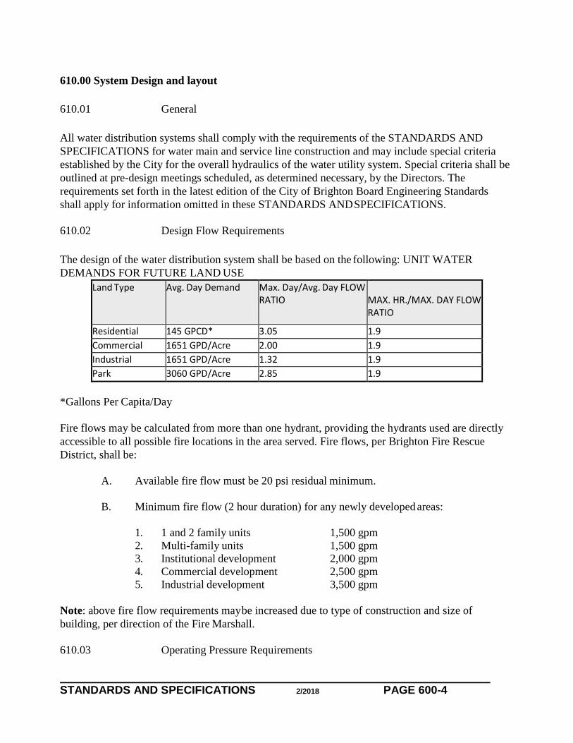
610.02 Design Flow Requirements
The design of the water distribution system shall be based on the following: UNIT WATER
DEMANDS FOR FUTURE LAND USE
Land Type Avg. Day Demand Max. Day/Avg. Day FLOW RATIO
MAX. HR./MAX. DAY FLOW RATIO
Residential 145 GPCD* 3.05 1.9
Commercial 1651 GPD/Acre 2.00 1.9
Industrial 1651 GPD/Acre 1.32 1.9
Park 3060 GPD/Acre 2.85 1.9
*Gallons Per Capita/Day
Fire flows may be calculated from more than one hydrant, providing the hydrants used are directly
accessible to all possible fire locations in the area served. Fire flows, per Brighton Fire Rescue
District, shall be:
A. Available fire flow must be 20 psi residual minimum.
B. Minimum fire flow (2 hour duration) for any newly developed areas:
1. 1 and 2 family units 1,500 gpm
2. Multi-family units 1,500 gpm
3. Institutional development 2,000 gpm
4. Commercial development 2,500 gpm
5. Industrial development 3,500 gpm
Note: above fire flow requirements may be increased due to type of construction and size of
building, per direction of the Fire Marshall.
610.03 Operating Pressure Requirements

STANDARDS AND SPECIFICATIONS 2/2018 PAGE 600-5
All areas shall be designed to provide a maximum static head of two hundred fifty four (254) feet
(one hundred ten [110] psi) and a minimum static head of ninety two (92) feet (forty [40] psi).
Distribution systems shall also be designed to maintain a twenty (20) psi residual pressure during
required fire flow. The maximum pressure drop from static head to either fire flow or peak
residential flow shall not exceed thirty (30) psi.
Fire hydrant flow tests must be performed in order to determine exiting system pressures. Flow
testing must be performed by licensed and insured testing companies and shall be accompanied by
City Personnel when operating valves and hydrants on City water mains. The Brighton Fire Rescue
District and the Utilities Department shall review flow data and comment on system pressures, and
safety factors that are applied.
610.04 Sizing of Distribution Mains
Mains shall be sized large enough to provide for domestic, irrigation, and fire protection flows to
the area requesting service but not so large as to cause water quality issues. The maximum
acceptable head loss for 8 and 12-inch mains is 2 feet per 1,000 feet of main for the maximum hour
flow using a C-value of 130; however, this does not apply under fire flow conditions.
Distribution mains shall also be sized for fire protection utilizing maximum day flows and needed
fire flow resulting in a minimum residual pressure no less than 20 psi in the localized area of
interest. The City reserves the right to size mains to accommodate future needs.
New mains shall be 8, or 12 inch as set by the City. If approved by the City in writing, mains
smaller than 8-inches may be used in some cul-de-sacs without a fire hydrant. Dead-end mains in
cul-de-sacs will be evaluated to determine if the appropriate number of services exist to maintain
water quality turnover.
Fire flow evaluations with one side of the loop out of service (i.e., worst case scenarios) are a
normal part of the distributions system’s main size evaluation. Consideration will be given
wherever water quality problems are caused by an upsizing of the main. Exceptions to looping are
subject to the City’s discretion and additional requirements. The City will analyze the water system
for developing areas to determine their adequacy. Parallel mains are not allowed.

STANDARDS AND SPECIFICATIONS 2/2018 PAGE 600-6
610.05 Fire Protection Systems
610.05.01 Fire Hydrants
The fire hydrant branch line shall be set at a 90 degree angle to the street main. The hydrant shall be
set at the end of the branch line facing the branch line. Horizontal bends, vertical bends, or reducers
shall not be used in the fire hydrant branch line unless specifically approved in writing by the
Utilities Director. Under no circumstances shall any size or manner of tap be made on a fire hydrant
branch line.
A dead-end main may only have one fire hydrant connected to it in cases where looping is not an
alternative, except as specifically approved in writing by the Utilities Director.
Redundant hydrant installation and the unnecessarily high density of fire hydrants should be
avoided where existing hydrant function would be duplicated. These types of hydrant requests will
be reviewed by the City and approved at its discretion. The review will be based on the number of
fire hydrants in close proximity, hydraulic analysis, and correspondence with Greater Brighton Fire
Authority.
610.05.02 Fire Hydrant Spacing
In single-family residential areas, fire hydrants shall be spaced a maximum of five hundred (500)
feet apart as measured along street curb line and at an overall spacing that will average not less than
one hydrant to two hundred thousand (200,000) square feet accessible to the fire hydrant throughout
an individual subdivision. Fire hydrant locations shall be approved by Brighton Fire Rescue
District.
In business, industrial, and high-density residential areas, hydrants shall be spaced not greater than
three hundred feet (300) apart or as approved by Greater Brighton Fire Authority.
610.05.03 Fire Lines
Connections made to existing mains that run to the property line and provide water for fire
protection systems are known as firelines. Fireline sizes are determined by those persons
responsible for protecting the structures served.
The fireline shall be installed at a right angle to the distribution main and shall run straight from the
main to the property line. Horizontal or vertical bends shall not be installed in the line; however,
bends may be installed when making a wet tap where the tap location conflicts with an existing pipe
joint or where interference prohibits a straight-line installation. Such horizontal or vertical bends
shall be used only when specifically approved in writing by the Utilities Director.

STANDARDS AND SPECIFICATIONS 2/2018 PAGE 600-7
Multiple fire protection appurtenances, including any combination of fire hydrants and firelines for
any single project site, are not allowed on a dead-end main. Additional consideration will be given
in the case of single-family residential homes on a cul-de-sac where firelines are required.
The property owner shall maintain all fire lines extending from the valve on the City water main.
Valves on newly constructed fire lines shall be located on the tee at the main line. Fire lines are to
be used exclusively for fire protection. Domestic water taps and/or irrigation taps shall not be
allowed on the fire line. Fire lines valve boxes will have “FIRE” printed on the valve lid instead of
“WATER”.
610.06 Cross-Connection Control and Backflow Prevention
610.06.01 Cross-Connection Control
The City is responsible for protecting its public water system from contamination due to backflow
occurrences through residential, multi-family, irrigation, and/or commercial property water service
connections (i.e. cross-connections). The City needs assistance and the cooperation of the public
and Developer and/or Applicant to ensure this responsibility is met. The City may request access to
property or facility to conduct an on-site cross-connection control survey.
A properly designed air-gap is the most effective method of protecting the public water supply from
high hazard cross-connections. When an air-gap cannot be used, a RP BFPA shall be installed. The
City requires the installation of a containment assembly on commercial property service lines.
Failure to comply with the installation and annual testing requirements may result in suspension of
service.
610.06.02 Approved BFPA
Manufactured in accordance with AWWA C510 and C511 and meeting USC FCCCHR
specifications.
Foundation for Cross-Connection Control and Hydraulic Research
School of Engineering MC-2531
University of Southern California
P.O. Box 77902
Los Angeles, CA 90007
Foundation Office: (866) 545-6340
http://www.usc.edu/dept/fccchr/

STANDARDS AND SPECIFICATIONS 2/2018 PAGE 600-8
610.06.03 Requirements for Approved USC FCCCHR BFPA Installations Based on the
Degree of Hazard
610.06.03.01 A Commercial domestic service line tap
Requires an approved RP to be installed on the domestic water service line 5 feet downstream from
the meter pit or immediately upon entry into a heated part of the building 5 feet (maximum) from
the wall or floor before any connections.
610.03.03.02 A commercial fireline service tap
Installed as a wet pipe with the use of chemical additives or pumps requires an approved RP to be
installed on the fireline downstream from the tapping valve and immediately upon entry into a
heated part of the building 5 feet (maximum) from the wall or floor before any connections.
Installed as a wet or dry pipe system without the use of chemical additives or pumps, requires a DC
to be installed on the fireline downstream from the tapping valve and immediately upon entry into a
heated part of the building 5 feet (maximum) from the wall or floor before any connections.
Branch lines and taps are not allowed on firelines downstream from the designated containment
BFPA for any purpose other than fire protection (additional protection may be required).
610.06.03.03 A commercial irrigation service line tap
Requires an approved RP to be installed on the irrigation water service line 5 feet downstream from
the meter pit; the line must be above ground before any connections.
Branch lines and taps are not allowed on dedicated irrigation water service lines for domestic
(potable) use.
610.06.03.04 A commercial drinking fountain domestic service line tap
Requires an approved DC to be installed on the domestic water service line:
1. Above ground, 5 feet downstream from the meter pit in a properly securable BFPA box,
either standard or heated depending on need.

STANDARDS AND SPECIFICATIONS 2/2018 PAGE 600-9
610.06.03.05 A multi-family domestic service line tap
Requires an approved RP or DC acting as containment if:
1. the premises is over three stories (taller than 30 feet);
2. the premises has a fire protection system;
3. the premises has a common boiler; or has only one service connection feeding multiple
units.
The BFPA shall be installed on the domestic water service line 5 feet downstream from the meter
pit or immediately upon entry into a heated part of the building 5 feet (maximum) from the wall or
floor before any connections.
610.06.03.06 A single-family domestic service line tap with a Dual Water Supply
Agreement
It is at the sole discretion of City of Brighton’s Cross- Connection Control Section to determine that
existing auxiliary water supply poses a high risk to City of Brighton’s potable distribution system.
The installation of a RP will be required 5 feet downstream from the meter pit in an above ground,
heated enclosure before any connections.
It is at the sole discretion of City of Brighton’s Cross-Connection Control Section to approve the
proposed BFPA installation. The approved BFPA may not be removed, relocated, or altered without
approval by City of Brighton.
610.06.04 Examples of BFPA Installations
The following facilities represent high hazard commercial applications that must be contained from
City of Brighton’s distribution system by a USC FCCCHR approved containment RP BFPA:
1. Amusement parks
2. Autopsy facilities
3. Auxiliary water supply
4. Battery shops
5. Car wash facilities
6. Chemical plants

STANDARDS AND SPECIFICATIONS 2/2018 PAGE 600-10
7. Cooling towers
8. Community gardens
9. Dental clinics
10. Dry cleaners
11. Electrical and electronic component manufacturers
12. Firefighting systems
13. Food and beverage processing plants
14. Gas stations
15. Green courts
16. Golf courses
17. Greenhouses
18. Health spas
19. Hospitals
20. Hotels
21. Hydraulic testing facilities
22. Irrigation systems
23. Jewelry manufacturers
24. Kennels
25. Laboratories
26. Laundromats
27. Manufacturing facilities
28. Medical facilities

STANDARDS AND SPECIFICATIONS 2/2018 PAGE 600-11
29. Metal plating industries
30. Mobile home parks
31. Morgues
32. Mortuaries
33. Motels
34. Multistory buildings (higher than 30 feet above the ground line)
35. Packing plants
36. Parks and recreation centers
37. Petroleum refineries
38. Pet shops
39. Photographic film processing facilities
40. Printing or screen printing shops
41. Radiator shops
42. Radioactive material processing plants
43. Recycled water systems (chemical injection, booster pumps, or high risk scenarios)
44. Rendering plants
45. Recreational vehicle dump sites
46. Salons
47. Schools
48. Sewage treatment plants or facilities
49. Solar water heating units
50. Steam generating facilities

STANDARDS AND SPECIFICATIONS 2/2018 PAGE 600-12
51. Stock yard facilities
52. Swimming pools
53. Tanneries
54. Tattoo parlors
55. Taxidermy shops
56. Warehouses
57. Water features
58. Water play features
59. Waterfront facilities
60. Zoos
610.06.04.01 A USC FCCCHR approved RP BFPA is required when:
A. High-level security or restricted commercial properties do not allow City of Brighton to
gain access to conduct a cross-connection control survey of the property and/or facility. An
approved RP assembly shall be installed 5 feet downstream from the existing meter pit in
an above ground, heated enclosure.
B. A landscape irrigation system is designed for the direct injection of chemical additives into
the system. An approved RP assembly shall be installed on the designated service line to
the premises 5 feet downstream from the meter pit or before any valves or branching.
C. All containment assemblies shall be tested and the report sent to City of Brighton’s Cross-
Connection Control Section annually.
D. A RP BFPA is required for irrigation system installations that are 2-inches in diameter or
less:
1. An approved USC FCCHR RP BFPA shall be installed on the irrigation water
service line 5 feet downstream from the meter pit; the line must be above
ground before any connections.
2. Branch lines or taps are not allowed on dedicated irrigation water service lines
for domestic (potable) use.
610.06.04.02 A DC BFPHA is required when:

STANDARDS AND SPECIFICATIONS 2/2018 PAGE 600-13
A. Fire protection systems are installed without chemical additives or pumps. An approved
DC or RP BFPA shall be installed on the designated water service line entering the
building (i.e., the Mechanical Room or the Pump Room).
610.06.05 Testing Requirements for Backflow Prevention Assemblies Installed on
potable Water Services
The Developer and/or Applicant is required to have a certified ABPA or ASSE tester inspect and
test an existing or newly installed containment BFPA on dedicated water service lines, if applicable,
upon installation and annually thereafter. Tests shall be conducted at the expense of the Developer
and/or Applicant. BFPAs shall be repaired or replaced at the Developer and/or Applicant’s expense
when found to be defective. Records of tests, repairs, and replacements shall be kept by the
Developer and/or Applicant and a copy of the annual test provided to City of Brighton. The use of
video inspection is permitted with designated potable water only equipment in accordance with City
of Brighton’s Operating Rules.
610.06.05.01 The tester is required to:
A. Complete BFPA testing and submit test reports within 48 hours of City of Brighton’s
setting of the meter and turning on of the water service.
B. Submit a copy of the official ABPA or ASSE certification to City of Brighton’s Cross-
Connection Control Section each time the certification is renewed.
C. Submit a copy of the test kit calibration certification annually.
D. Complete the BFPA test report and submit a copy of the containment BFPA report to City
of Brighton’s Cross-Connection Control Section within 5 days.
E. Indicate containment or containment by isolation on the test report.
F. The submission of isolation test results to City of Brighton is not required by the CDPHE.
G. Indicate the type of usage (i.e., domestic, irrigation, or fireline) on the test report.
H. Confirm the premises ID, City of Brighton Service Address, location of assembly on
premises, BFPA serial number, and record the values on the test report with a clearly
marked pass of fail indication.
I. Contact City of Brighton’s Cross-Connection Control Section for discrepancies regarding
the meter or BFPA.
J. Sign, date, and include the time of the test on the report.

STANDARDS AND SPECIFICATIONS 2/2018 PAGE 600-14
Required test reports shall be submitted to City of Brighton’s Cross- Connection Control office:
Mailing Address:
City of Brighton Utilities Department
Attn: Cross-Connection Control
500 S. 4th Ave.
Brighton, CO 80601
610.06.05.02 Failed Assemblies
A. If the BFPA fails and cannot be repaired on the day of its failure, the Cross-Connection
Control Section must be notified by the certified ABPA or ASSE tester within 24 hours. A
copy of the failed test report must be submitted to the Cross- Connection Control Section
within 3 days.
B. The Property Owner is responsible for coordinating the necessary repairs to the BFPA and
retesting the unit within 5 days. The Owner must submit a passing test report to the Cross-
Connection Control Section. Failure to comply may result in the suspension of water
service.
C. If the premises has a high health hazard BFPA and is deemed a threat to public health (via
the private plumbing system), it is at City of Brighton’s discretion to suspend the dedicated
water service line immediately. The customer shall repair or replace the BFPA before
water service will be restored.
610.06.05.02 Exemptions
Single-family residential customers are exempt from City of Brighton’s cross-connection control
requirements unless the premises is served by an auxiliary water supply (e.g., raw water, a well, a
lake, a pond, or a ditch) or has a dedicated city metered service line for irrigation only. Auxiliary
water supply conditions require a Dual Water Supply Agreement to be in effect between City of
Brighton and the Property Owner. Multi-family residential customers are exempt from City of
Brighton’s cross-connection control requirements if each unit has an independent service line.
For questions or concerns related to cross-connection control, please contact City of Brighton’s
Cross-Connection Control Section.
610.07 Pressure Reducing Stations
PRV installations are used to control pressures within the distribution systems. When main
extensions are submitted for review, the need for a PRV installation will be determined based on

STANDARDS AND SPECIFICATIONS 2/2018 PAGE 600-15
existing pressure zones and the existing distribution system layout. PRV settings are to be included
on plans with the elevation and the upstream and downstream hydraulic grade line and pressure.
The City will make pressure settings and field adjustments.
610.08 Storage Facilities
610.08.01 Installation
Water Storage facilities are allowed for the storing of water from City of Brighton’s water system
where specifically authorized and approved in writing by the Utility Director.
610.08.02 Cleaning and Drainage
Storage facilities shall have built in provisions for draining as well as access and provisions for
cleaning including a suitable source of water. The cleaning and drainage facilities shall be subject to
the City’s approval.
610.08.03 Electronic Monitoring Equipment
The City may require the installation of SCADA equipment for storage facilities of the type
specified by the City.
610.09 Distribution System Layout
610.09.01 General
Mains shall be installed in dedicated public streets. Main layout shall be of such grade, alignment,
curvature, and other characteristics as to permit installation and maintenance in the usual manner.
The condition under which such an exception is allowed will be determined on a case-by-case basis.
Only easements in accordance with the terms of the City standard easement form and these
Standards will be accepted. Easements granted for water mains near the perimeter of a lot or
property line must about the lot or property line to provide for future domestic and/or fire protection
service from the water main to the adjoin lot or property, except as specifically approved in writing
by the Utilities Director.
Distribution systems shall be design so that no critical pipes exist. A critical pipe is any length of
pipe, excluding private services, that when damaged, shut off, or otherwise taken out of service,
does not isolate any development, subdivision, complex or other water using use.
610.09.02 Location (Typical)
Water mains will typically be located five feet (5') north or east of the centerline of the street unless

STANDARDS AND SPECIFICATIONS 2/2018 PAGE 600-16
otherwise approved by the Directors.
At street intersections, valves will be located at tees or cross with 5’ of separation between valves.
Fire hydrant gate valves shall be placed at swivel tee. All fire hydrants shall have a restrained
connection directly to the tee off the main (see the Standard Drawings).
In all instances, the water mains shall extend to the boundary line of the property or subdivision
served. A main serving one lot shall extend the entire way across the frontage for that lot. Mains
serving a subdivision shall extend to the center of boundary streets, to boundary lines or to the
outside of paved areas as may be noted on the accepted plans.
610.09.03 Pipe Deflection
Deflection of PVC pipe and Ductile Iron pipe may be achieved by deflection according to
manufacturer’s recommendations only. Changes in direction greater than allowable deflection of
waterline pipe shall require bends.
610.09.04 Minimum Depth
All pipe shall be installed with a minimum of four feet six inches (4'-6") of cover from finished
grade of street to the top of the pipe barrel. Trenching, backfilling and compacting shall be
completed in accordance with Section 350.00, Trenching, Backfilling and Compacting, of these
STANDARDS AND SPECIFICATIONS.
610.09.05 Fire Hydrants
Fire Hydrants shall be installed within public streets or in easements. When the City determines it is
not feasible for a hydrant to be installed in this manner, it shall be installed in an easement adjacent
to the street. The fire hydrant easement shall have a minimum width of ten (10) feet if the length of
the easement is twenty-five (25) feet or less. Fire hydrant easements shall have a minimum width of
30 feet when the length of the easement is more than twenty-five (25) feet. The easement shall
extend a minimum of five (5) feet beyond the center of the hydrant.
Fire hydrants shall only be installed at locations authorized by the Brighton Fire Rescue District.
610.09.06 Line Valves
Valves shall be placed with a maximum spacing of five hundred (500) feet in all distribution mains
and lateral lines. Valves shall also be placed to insure that only one hydrant will be out of service in
the event of a line break.
Tees shall require three (3) valves. Crosses shall require four (4) valves. For a succession of short
blocks perpendicular to the direction of the distribution main and without residential or commercial

STANDARDS AND SPECIFICATIONS 2/2018 PAGE 600-17
services between, one or more intersection(s) shall have the valve in that direction omitted, but
must maintain the five-hundred (500) foot maximum spacing requirement.

STANDARDS AND SPECIFICATIONS 2/2018 PAGE 600-18
Valves shall also be placed at each end of a line running through an easement on private property,
on each side of a major creek or channel crossing, and on each side (at property lines extended) of a
distribution line that provides service to a hospital, school or large industrial user.
610.09.07 Air Relief Valves
Air relief valves shall be installed at each high point in all distribution mains and at high points of
lateral lines. Air relief valves shall be sized and located appropriately.
Air relief valves shall be installed in precast manholes or vaults fitted with air vents open to the
atmosphere and in accordance with the Standard Drawings.
610.09.08 Blow-off Valves
Provisions shall be included in the design to allow for the flushing of distribution mains and lateral
lines at any low point in the system, or at any point noted on the accepted plans. The blow- off
assembly shall be installed perpendicular to and on the downhill side of the main or line and shall
drain to the nearest gutter line or drainage channel. The blow-off assembly standpipe must have a
threaded end to accept a fire house coupling. The top of the standpipe shall be between four to six
inches (4”-6”) below grade in accordance with the Standard Drawing.
Permanent dead ends shall be provided with a permanent blow-off or fire hydrant and temporary
dead ends such as phasing within developments, shall have temporary blow-offs (See Standard
Details).
620.00 Service lines, firelines, meters, and appertenances
620.01 General
Water is conveyed from mains to consumers by service lines and their associated appurtenances.
Except for fireline services, water delivered to customers must be metered. In the context of these
Standards, the service line includes pipe, fittings, and appurtenances that belong to the Developer
and/or Applicant that are used to convey and measure water from the distribution system to the
consumer for domestic, industrial, or irrigation use. The service line extends from the corporation
stop or tee on the water main to the first valve inside the premises after the water meter or BFPA, if
present. Water pipe beyond service lines shall be controlled by local plumbing codes.
620.02 Layout of Service Lines
620.02.01 General Layout

STANDARDS AND SPECIFICATIONS 2/2018 PAGE 600-19
The service line shall be arranged to provide convenient access to the curb stop and meter pit or
vault for meter reading, operation, and maintenance. Wherever possible, the pit or vault shall be
accessible from a paved street or the City easement that is accessible to maintenance vehicles and
shall have line-of-sight to a public street. The curb stop or property line valve shall be located
behind the curb line of the street as close to the curb as possible, in a landscaped or grassy area.
The water meter pit or vault shall be located in a landscaped area that is 2 to 5 feet after the curb
stop or property line valve. If there is a tree lawn between the curb and the sidewalk, the stop box
and meter setting shall be installed in the tree lawn. The public ROW or easement is preferred over
private property. The meter setting shall be within 5 feet of the public ROW or the City easement.
Curb stops and meter settings shall not be placed behind existing or future fences or walls that may
block access from the public ROW or easement. The area around the stop box and meter vault shall
be kept free of vegetation, structures, or other objects that may interfere with access.
In urban landscaped areas, stop boxes and meters may be placed in paved walkways with prior
written approval from the Utility Director. Stop box and meter pit or vault lids shall be carefully
adjusted to match the finished surface of the paved walk.
Stop boxes and meter pits or vaults shall be located to provide a minimum of 5 feet of clearance
from any building, retaining wall, fence, transformer pedestal, fireline, or other permanent
obstruction. The distance shall be measured from the outside wall of the valve box or the meter pit
or vault.
620.02.02 Location
The premises to be served shall have a minimum frontage of ten (10) feet on the street or easement
containing the water main to be tapped. The main shall extend a minimum of eight (8) feet along
the front lot line of the premises. The tap and service line shall be located entirely on or in front of
the premises to be served.
620.02.03 Setbacks
The service line, to a point five (5) feet past the meter pit or vault, shall be a minimum of five (5)
feet from any side property line. In the case of corner lots with frontage on two streets with water
mains, the property may be served from either the front or the side of the lot.
The tap at the main shall be at least five (5) feet from the side property lines extended to the main
and at least 3 feet from any pipe joint or fitting or from the end of any pipe segment.

STANDARDS AND SPECIFICATIONS 2/2018 PAGE 600-20
620.02.04 Alignment
The service line shall be installed in a continuous straight line, perpendicular to the property line or
curb, from the tap to a point 5 feet past the back wall of the meter pit or vault. The tap, stop box,
and meter pit or vault, shall be in a straight line.
620.02.05 Cul-de-Sacs
If service is requested for lots at the end of a cul-de-sac, the main to be tapped shall be within 50
feet of the front property line of each lot to be served in the cul-de-sac.
620.02.06 Depth of Service Line
Service lines shall be installed 4 1/2 to 6 feet below the ground line. If the water main is less than 4
1/2 feet, or more than 6 feet below grade, the service line shall be brought to an acceptable depth as
close to the main as possible. The depth from ground line to the curb stop or property line valve-
operating nut shall not exceed 6 feet.
If the grade of the surface is raised or lowered after a service line is installed, the Developer and/or
Applicant is responsible for the lowering or relocation of the service to maintain cover between 4
1/2 and 6 feet.
620.02.07 Identifications Tags
In cases where there may be confusion as to the property or building serviced by a service line, an
engraved plastic tag shall be attached to the meter yoke in the pit or vault using a stainless steel
braided wire. The tag shall be a minimum of 1 1/2 by 4 inches, 1/16 inch thick, with no more than
three lines of text and a hole to accept the wire. The top and middle lines shall display the assigned
service address and the building identification, if appropriate; the bottom line shall display the City
tap number. The tag shall have white letters engraved in a solid color. Tags for domestic services
shall be blue, irrigation-only services shall be green, recycled water services shall be purple, and
firelines shall be red.
620.02.08 Paved Areas
Care shall be taken to ensure that service lines do not enter the property at a driveway or walkway.
Service lines installed prior to the layout of property improvements may require reconstruction or
relocation prior to activation to avoid driveways and other paved areas. Bends, offsets, and similar
modifications of the straight-line layout requirements are not permitted. In cases where a
landscaped area does not exist between the building and the street or easement, the curb stop and
meter may be installed in the sidewalk or in a similarly paved surface provided the installation is
not subject to vehicle traffic, with the written approval of the Utilities Director.

STANDARDS AND SPECIFICATIONS 2/2018 PAGE 600-21
Special construction details shall be required and curb stops shall be placed under road boxes
instead of curb boxes.
620.02.09 Deviations
The Utilities Director may authorize deviations to the service line standards contained in this
Section. Deviations shall be requested in writing by the Applicant or the Applicant’s authorized
representative. Each request shall be considered on a case-by-case basis and shall not be considered
a precedent for any other location. Requests shall include sufficient information to justify the need
for deviation from the Standards and may include site plans, proposed service, meter
configurations, or other information requested by the Utilities Director.
620.02.10 Stub-ins
When a stub-in connection is installed to permit street paving or in advance of future development,
it shall be located to provide a future connection that is in accordance with applicable standards at
the time of activation. There is no assurance that any stub-in will meet the requirements for
conversion to a service line at the time of activation. A Developer and/or Applicant that installs a
stub-in does so with the understanding that it shall be the responsibility of the Developer and/or
Applicant to modify, reconstruct, relocate, replace, or remove the stub- in, as necessary, prior to
converting it to a service line to meet current Standards. Stub-ins and converted service lines may
not be located in a manner wherein the stop box and meter setting are beneath a driveway, sidewalk,
street, parking area, or within specified limits of side lot lines and permanent obstructions. Water
may not be taken from a stub-in for any purpose.
620.02.11 Compaction
Backfill material around service lines, stop boxes, and meter settings shall be carefully compacted
in accordance with the requirements of Section 300.
620.03 Separate Trenches
Service lines may be installed in trenches containing pipes that carry potable water; they may not be
installed in trenches with pipes carrying other substances. A service line shall be separated laterally
from foreign pipes by a minimum of ten (10) feet. However, a service line may be placed in the
same trench with other pipe when:
A. The adjacent foreign pipe is ductile iron.
B. The bottom of the service line is at least 12 inches above the top of the adjacent pipe and is
placed on a shelf excavated on one side of the common trench with a minimum horizontal
clearance of 5 feet.

STANDARDS AND SPECIFICATIONS 2/2018 PAGE 600-22
620.04 Pumps
Pumps are not allowed for the sole purpose of decreasing the size of the tap/meter and service line.
620.05 Tanks
Tanks are not allowed for the sole purpose of decreasing the size of the tap/meter and service line.
620.06 Connections for Water
620.06.01 Small Taps, 2-inches and smaller
Connections for domestic, irrigation, or fire service taps that are 2-inches and smaller will be made
by the Contractor and witnessed by a Utilities Inspector. The connection shall be made using a
corporation stop of the same size as the service line through a bronze tapping saddle, both of which
shall be supplied by the Developer and/or Applicant.
Taps shall be made only after satisfying the following conditions:
1. The main has been released by City of Brighton following the completion of the conditions
and tests of inspections.
2. Appropriate fees and charges have been paid to the City of Brighton.
3. Underground utilities near the tap are marked.
4. Tapping materials are on-site.
5. Front property corners are clearly staked and the service address visibly posted.
6. Water main valves are marked or staked.
7. Safety equipment and procedures are in place including trench shoring.
8. The service line, curb stop, meter pit, and meter yoke are installed and ready for connection
to the corporation stop.
9. The tapping location on the main is excavated and the water main surface is exposed and
clean.
620.06.02 Large Taps, 3-Inches and Larger

STANDARDS AND SPECIFICATIONS 2/2018 PAGE 600-23
Service connections to the main for service lines 3-inches and larger shall be made by a tee
connection. Domestic service taps 3-inches and larger may be installed by the Contractor and
witnessed by a Utilities Inspector. For the City installed connections, the Contractor shall excavate
the ditch and around the water main exposing it on all sides. The City will provide and install the
tapping saddle, tapping sleeve, or cut-in tee at cost. The Contractor shall connect to the outlet,
install the piping, set the valve boxes, and backfill the trench.
620.06.03 Insulators
Domestic service lines of dissimilar metals shall be electrically insulated by means of City of
Brighton approved insulating fittings or gaskets. Care shall be taken to properly install corporation
stops and provide enough slack in the service lines to protect against pullout.
620.06.04 Tapping Polyethylene Encased Pipe
When tapping mains, dig out bedding material and apply two to three wraps of adhesive tape
completely around the polyethylene-encased pipe to cover the area where the tapping saddle and
machine is to be mounted. After the tapping machine is mounted, install the corporation stop
directly through the tape and polyethylene. After the tap is complete, the entire area shall be
inspected for damage and repaired if necessary. Any bedding material removed during excavation
shall be replaced in kind and compacted in accordance with Section 300.
620.06.05 The Spacing of Service Taps
Multiple taps on the same side of the main shall be a minimum of 5 feet apart, measured
longitudinally along the centerline of the main. Multiple taps on opposite sides of the main shall be
staggered by a minimum of 2 1/2 feet, measured longitudinally along the centerline of the main.
Taps shall not be made within 3 feet of any main line pipe fitting.
620.07 Taps and Saddles
Tapping saddles with a tap size of 2-inches and smaller for ductile iron and asbestos-cement pipe
shall consist of a bronze body with two bronze straps. Saddles for PVC pipe shall be single strap
bronze saddle.

STANDARDS AND SPECIFICATIONS 2/2018 PAGE 600-24
Existing steel mains that are 20-inches in diameter or smaller shall be tapped using a method
approved by City of Brighton.
620.08 Size
620.08.01 General
Taps and service lines shall be of a size that is adequate to supply the requirements of the property
being served while not being so large as to cause inaccuracies in metering low flows. The minimum
size allowable for a service line shall be 3/4-inch.
The tap, corporation stop, meter, and that portion of the service line between the corporation stop and
5 feet past the meter shall be the same size. The service line may be increased in size to the next
approved larger diameter beginning 5 feet downstream of the meter. This is permitted to satisfy
maximum pressure loss criteria, it is not for achieving greater flow using a smaller tap.
Taps and services shall be sized to produce a water velocity that is no greater than 10 feet per second
at peak demand as estimated by an accredited Fixture Unit Count methodology.
Additionally, the total pressure drop in the service line from the main to the building shall not exceed
25 psi without backflow prevention or 30 psi and a minimum residual pressure of 20 psi at the
building beyond any backflow prevention under peak domestic demand flow. Additional fire flow
demand and service sizing shall be the responsibility of the Developer and/or Applicant or the
Developer and/or Applicant’s Professional Engineer.
620.08.02 Multi-Family Buildings
In addition to the general requirements, the minimum tap size for domestic service shall be based on
the number of units in the building:
Units Tap Size (Inches)
1-2 ¾
3-5 1
6-25 1 ½
26-50 2
These estimates are for minimum estimated tap, service, and meter sizing. Actual sizing should be
based on flow that is calculated from an accredited Fixture Unit Count methodology that varies
dependent on the actual number of fixtures within each unit and within the overall building supplied.
Buildings with more than 50 units will be evaluated on an individual basis. In special circumstances,
City of Brighton may require a larger minimum tap size. Additional flow demands required to meet
NFPA 13R shall be evaluated by the Developer and/or Applicant or the Developer and/or
Applicant’s Professional Engineer and services sized accordingly.
STANDARDS AND SPECIFICATIONS 2/2018 PAGE 600-25
620.08.03 NFPA 13D Residential Sprinkler Services
For residential services meeting NFPA 13D, the tap, corporation stop, meter, and that portion of the
service line between the corporation stop and 5 feet past the meter shall be the same size. The
service line may be increased in size to the next approved larger diameter beginning 5 feet
downstream of the meter. The appropriate design of the NFPA 13D fire sprinkler system shall be
the sole responsibility of the Developer and/or Applicant.
620.08.04 Irrigation Service
For irrigation services, the tap, corporation stop, meter, and that portion of the service line between
the corporation stop and the valve before the BFPA shall be the same size. The service line may be
increased in size to the proper design size for the BFPA beginning at least 5 feet downstream of the
meter pit or vault. Additional pipe increases are permitted after the BFPA to satisfy the maximum
design water velocity in the irrigation system.
620.09 Pipe Material
Pipe material is dependent on the size of the service line:
A. Seamless Copper Tube: Shall be used for service lines 3/4 through 2-inches
B. Ductile Iron Pipe: Shall be used for service lines 3 inches and larger.
620.10 Curb Stops, Valves, and Valve Boxes
A curb stop or gate valve of the same size as the service line shall be installed on every service line.
Buried valves and curb stops shall be equipped with a cast iron valve box and large oval base. When
a 3/4 or 1-inch curb stop is placed in paved areas, a roadway box shall be used.
Compression fittings at the curb stop may be used on pipe that is less than 2-inches in diameter.
620.11 Meters
620.11.01 General
Meters shall not be installed until the proposed installation is approved, and the meters tested and
numbered by City of Brighton.

STANDARDS AND SPECIFICATIONS 2/2018 PAGE 600-26
Service meters are used to record usage by the retail customer. Master meters are used by wholesale
customers and supply water to service meters. Other temporary meters exist in the system for testing
and measuring water usage from fire hydrants.
Accuracy, sensitivity, durability, low pressure loss, life-cycle cost, ease of use, and low cost of
maintenance are important characteristics of meters. As such, City of Brighton will determine
acceptable meter manufacturers and models.
Meter installations will be inspected by City of Brighton upon completion of the installation and
prior to backfilling.
620.11.02 Size of Meter
Meters shall be the same size as the corporation stop or service tee and that portion of the service
pipe between the meter and the corporation stop. A meter that is smaller than 3/4-inch shall not be
installed unless it is to serve as a replacement for an existing small meter.
In cases where the full capacity of a previously used service pipe is not required, City of Brighton
may allow for the installation of a meter that is smaller than the service pipe provided the service
pipe is reduced to the size of the meter for a distance of no less than 10 times the larger pipe
diameter on the inlet side of the meter, or 5 feet, whichever is longer.
620.12 Outside Meter Setting
Outside meters shall be installed with the inlet and outlet spuds in a horizontal position and housed
in a concrete or approved composite meter pit or vault in accordance with the Standard Drawings.
The meter shall be installed in an approved coppersetter or yoke. Coppersetters for meters 1-inch
and smaller shall be installed with the meter spuds located 18 inches below the meter pit lid to
facilitate maintenance and replacement. The meter shall sit vertically with the meter register up.
Larger meters shall be installed in vaults in accordance with the Standard Drawings. Deviations in
installation height, spacing, pipe location, mounting supports, and other details must be approved in
advance in writing by the Utility Director.
620.13 Meter Bypass Lines
A bypass line is required for 1 1/2-inch and larger meters, except those used for irrigation-only
service, whether installed in an outside or inside setting. Bypass lines shall contain an independent
control valve and shall not contain tees, plugs, or other outlets through which water could be
withdrawn. Bypass lines permit the customer to have water while the meter is being repaired or
replaced and may only be activated by City of Brighton. Bypass lines for 1 1/2 and 2- inch meters
shall be integral to the meter yoke with an appropriately sized ball valve. Bypass lines for 3-inch
and larger meters shall be connected to the main line at tees before and after the meter and shall

STANDARDS AND SPECIFICATIONS 2/2018 PAGE 600-27
include a gate valve with wheel operator. Bypass lines shall be locked in the closed position when
not in use.
620.14 Abandonment or Removal of Service Lines and Tap Cuts
It may become necessary to remove or abandon a service line or stub-in due to redevelopment, and
changes in water requirements for the premises or to relocate a service due to changes in the
configuration of the premises. An abandoned or relocated service line shall have the tap cut at the
main to ensure that it cannot be used to remove water from the system. Service line tap cuts shall be
witnessed by a City of Brighton Inspector. Tap cuts shall be coordinated through the Utility
Department. Taps that are 3-inches and larger shall require water plans for review. Service lines
must be metered until disconnected from the main in the presence of a City of Brighton Inspector.
620.14.01 Services, 2-inch and smaller
The service connection shall be excavated where the corporation stop is inserted into the water
main. The corporation stop shall be closed, the service tubing or piping shall be removed from the
corporation stop, the threads shall be scarred on the corporation stop, and a section of the water
service line at least 12 inches long shall be cut out. The curb or valve box over the curb stop shall
be removed in its entirety or cut off at least 18 inches below the ground line. The meter shall be
delivered to City of Brighton’s Water Shop for a final test and reading. The meter may not be used
again in the City of Brighton system. The meter pit, if present, may be removed in its entirety. If it is
left in place, it shall be cut off at least 18 inches below the ground line and filled with sand or other
fill material.
620.14.02 Services, 3-inch and Larger
The service connection shall be excavated over the service tee on the water main. The valve at the
main shall be removed and the connecting fitting (tee or tap) plugged. The property line valve box
shall be removed or cut off at least 18 inches below the ground line. The meter shall be delivered to
City of Brighton’s Water Shop for a final test and reading. The meter may not be used again in the
City of Brighton system. The meter vault, if present, may be removed in its entirety. If it is left in
place, it shall be cut off at least 18 inches below the ground line and filled with sand or other fill
material.
630.00 Materials
630.01 General
Furnished materials shall be new, undamaged, and the latest standard product of a manufacturer
regularly engaged in the manufacture of the product for at least 5 years. Everything necessary to

STANDARDS AND SPECIFICATIONS 2/2018 PAGE 600-28
complete installations in accordance with these Standards shall be furnished and installed including
items not shown on plans and Standard Drawings. Installations shall be finished as fully operable,
functioning parts of the City of Brighton system.
Approved Developers and/or Applicants shall provide the materials necessary for installation when
mains are extended; City of Brighton will not supply materials. Acceptance of the materials or the
waiver of an associated inspection shall in no way relieve the Approved Developer and/or
Applicant from the responsibility of furnishing materials that meet the requirements of the
Materials Specifications.
New water industry products or materials will be tested if, in the opinion of the Utilities Director, a
product or material has some merit. City of Brighton will establish the criteria for the testing and
evaluation of products. City of Brighton reserves the right to accept or reject any product or
material regardless of test results.
630.02 Size of Mains
The size of mains shall be in accordance with Section 610.04. Standard acceptable nominal
diameters of distribution mains are 8 and 12-inches. Standard acceptable nominal diameters of
transmission mains are 16 and 20-inches. Standard acceptable nominal diameters for conduits are
24-inches and larger.
630.03 Pipe Classes
City of Brighton has established minimum design safety factors for system piping considering
working pressures of 150 psi concurrent with a water hammer surge pressure of 110 psi for 4, 6, 8,
12 and 16-inch pipe, and 70 psi for 20-inch and larger pipe.
Based upon these considerations, the following minimum AWWA Standard pressure classes for
acceptable types of pipe are required:
Ductile Iron (DI) Special Thickness Class 50 (6, 8, 12, 16, and 20-inch)
Special Thickness Class 51 (3, 4, 24-inch)
Plastic (PVC) C 900 DR 14 (4-inch through 12-inch)
C 905 DR 18 (16-inch through 24-inch)
C 909 Pressure Class 305 (4-inch)
C 909 Pressure Class 235 (6, 8, and 12-inch)
630.04 Selection of Pipe

STANDARDS AND SPECIFICATIONS 2/2018 PAGE 600-29
In general, the selection of the type of pipe shall be left to the discretion of the Professional
Engineer in charge of the design. However, City of Brighton reserves the right to deny the use of
certain types of materials in specific circumstances.
Where joint restraint is required, the designer shall select a pipe along with an approved system of
restraint. Installation of metallic pipe and fittings in corrosive soil areas requires corrosion
protection systems.
The installation of mains through hazardous areas, at depths greater than 10 feet, and in the
roadways of state and federal highways may require the selection of pressure classes in excess of the
minimums stated in Section 630.03. Special comprehensive studies of applicable laws, regulations,
and detailed engineering calculations shall be submitted by the Approved Developer and/or
Applicant to City of Brighton for review in these instances.
When the installation of metallic pipe is contemplated, a soil resistivity survey of the construction
area shall be performed. The survey data and calculations coupled with the service history of other
existing pipes in the area shall be submitted by the Approved Developer and/or Applicant to City of
Brighton. Resistivity surveys shall utilize the Wenner four-pin method.
When water mains are to be constructed in soils that have a resistivity of less than 1,000 ohm-
centimeters or where stray current corrosion is expected to be severe, an approved nonmetallic pipe
system shall be selected. When water mains are to be constructed in soils that have a resistivity of
more than 1,000 ohm-centimeters, metallic or nonmetallic pipe material may be selected. Metallic
pipe, fittings, and appurtenances shall be protected against corrosion by polyethylene wrap in
accordance with Section 640.23 regardless of soil resistivity.
Nonmetallic pipe is not allowed in areas with soil contamination. Soil contamination that consists
of hazardous substances or materials or toxic substances will be determined on a case- by-case basis
by City of Brighton.
When a metallic pipe must be used in a low resistivity soil, additional cathodic protection may be
required, the design of which shall be specific to the project and subject to City of Brighton’s
approval.
630.05 Pipe Fittings
630.05.01 Joints
Joints and fittings shall be in accordance with applicable AWWA Standards and bear the pressure
rating of the straight pipe involved at a minimum. Acceptable types for straight lengths of pipe are
push-on, mechanical joint, and bell spigot restraint systems. Mechanical joints for straight lengths
of pipe will be allowed under specific situations with City of Brighton’s approval.

STANDARDS AND SPECIFICATIONS 2/2018 PAGE 600-30
Fittings shall be furnished with mechanical joint ends. The use of wyes is prohibited. Fittings shall be
fusion bonded epoxy coated.
630.05.02 Closure Fittings
Bolted sleeve-type couplings, in accordance with AWWA C219, shall be of a gasketed, sleeve- type
with a diameter that properly fits the pipe. Tolerance on the pipe and coupling together with proper
bolt and gasket arrangements shall be sufficient to ensure permanent watertight joints under all
conditions. Couplings shall be sufficiently wide so that each type of pipe joined has as much pipe
end inserted in the couplings as is provided by the standard push-on or mechanical joint for the pipe
size and type involved.
The following table contains the minimum center sleeve dimensions for bolted sleeve-type couplings:
Pipe Diameter (Inches) Center Sleeve Thickness (Inches) Center Sleeve Width (Inches)
4 0.250 5
6 0.250 5
8 0.250 5
12 0.375 7
16 0.375 7
20 0.375 7
24 0.375 7
Ductile iron sleeves shall have mechanical joints of the proper size and tolerance to ensure a
watertight fit.
Split sleeve couplings in accordance with AWWA C227 are acceptable.
Long bell closure pieces shall be equal in strength, at a minimum, to the straight pipe being joined
and shall contain push-on joints of the proper tolerance to ensure watertight connections.
Where pipes of different types are connected together or where pipe is connected to fittings or valves
of different materials, great care shall be taken to ensure the proper ring, insulating gasket, or adapter
is selected.
630.05.03 Miscellaneous Pipe Fittings
Flanged adapters, plugs, end caps, bulkheads, cut-in sleeves, anchor couplings, repair fittings, and
other appurtenances shall be used where appropriate throughout the system subject to City of
Brighton’s approval. Written requests for the approval of deviating items shall be made in advance

STANDARDS AND SPECIFICATIONS 2/2018 PAGE 600-31
through City of Brighton.

STANDARDS AND SPECIFICATIONS 2/2018 PAGE 600-32
630.05.04 Mechanical Joint Restraint Devices
The harnessing of joints may be accomplished by the use of one of the mechanical joint restraint
systems or by the use of one of the several proprietary joint restraint systems supplied by pipe
manufacturers. Proprietary systems will require City of Brighton’s approval prior to use.
Regardless of the system used, restrained lengths of pipe for various fittings where harnessing is
utilized or required shall be at least equal to the lengths shown on the Standard Drawings.
Where joint restraint is required on PVC pipe, the designer may use a joint restraint system of the
type supplied by pipe manufacturers and approved by City of Brighton or switch to a metallic pipe.
The use of rods and clamps on PVC pipe are not allowed.
630.06 Line Valves
Line valves shall be resilient seat gate valves. Valves shall be the same size as the main and shall
open counter-clockwise. Valves with operators that open clockwise shall not be used unless they
are required by, or approval is obtained from, City of Brighton.
630.07 Pressure Regulating Valves
A PRV is used to keep downstream pressure uniform and less than that in the upstream main.
They shall be sized so that the velocity through the valve at maximum demand does not exceed 25
feet per second. If a wide range of flow rates is anticipated, more than one valve may be required.
Care shall be taken to ensure an adequate pressure differential across the valve under all ranges of
flow to accomplish hydraulic throttling. When pressure differentials greater than 45 psi are
expected or when the downstream pressure are low relative to the differential, special valve
materials or a special valve design may be required.
PRVs shall be properly supported and have adequate clearance above and below the valve to
facilitate servicing. A manual bypass is required for single valve installations. Telemetering of data
may be required. Each PRV shall have a gate valve on both sides for isolation purposes.
630.08 Tapping Valves and Sleeves
Tapping valves and sleeves shall be used concurrently to tap an existing main that is in service and
under pressure without interrupting service. A tapping valve does not replace a property line valve;
however, a property line valve may not be required if the out-distance of the main is 15 feet or less.

STANDARDS AND SPECIFICATIONS 2/2018 PAGE 600-33
Connections to the main that are 2-inches and smaller shall be made by a corporation stop that is the
same size as the service line.
Connections to mains that are larger than 2-inches shall be made with an existing tee (cutting a tee
into a dewatered line if permitted by City of Brighton) or a tapping valve and a tapping sleeve.
Whichever method is used, care shall be exercised to select sleeves and gaskets that are properly
sized to fit the type and class of pipe to be tapped. Where tapping sleeves are used that are larger
than 2-inches, a thrust block shall be placed behind the tapping sleeve to prevent possible damage
to the main from pressure shocks that develop as valves are first opened.
630.09 Check Valves
A check valve permits flow in one direction only; it closes when the flow stops so reversal cannot
occur. They are required for meter installations 1 1/2-inches and larger where there is no BFPA
downstream. Check valves are not a substitute for BFPAs; however, they may be omitted from the
meter installation in cases where a BFPA is within 150 feet of the meter.
630.10 Stop and Waste Valves
Service lines shall have a stop and waste valve on the service line inside the residence (near where
the line enters the residence). The stop and waste valve shall have a drain plug located on the valve
body so that when the valve is shut off the drain plug can be removed and the water above the valve
drained out.
630.11 Valve Boxes
Buried gate valves that are 12-inches and smaller shall be provided with a 6-inch cast iron valve
box and large oval base. The valve box shall be of a design that shall not transmit shock or stress to
the valve and shall have enough extension capability to be raised to the ground line. The top section
of the valve box shall be acceptable for use with a butterfly valve.
630.12 Valve Reference Marker Posts
When valves are installed where adequate physical reference points are not available, as determined
by City of Brighton, a valve reference marker post may be required.
630.13 Water Meters
Water meters used in City of Brighton’s system shall be preapproved in accordance with the
approved manufacturer and model. City of Brighton will determine the type of meter to be installed
at the time of the application based upon size, service requirements, location, and other conditions

STANDARDS AND SPECIFICATIONS 2/2018 PAGE 600-34
that may exist. City of Brighton may change the type of meter at any time based on the water usage
patterns of the Developer and/or Applicant.
630.13.01 Magnetic Drive Displacement Meters
Displacement meters 5/8 through 3-inch, known as nutating-disc or oscillating piston meters, they
are positive in action. The pistons and discs displace or carry over a fixed quantity of water for each
nutation or oscillation when operated under positive pressure. Displacement meters are generally
used for residential, industrial, and commercial applications requiring a 3-inch or smaller service
and for irrigation services 1 1/2-inches and smaller. The 1-inch and smaller magnetic drive
displacement type water meter shall be furnished with a cast iron frost bottom.
630.13.02 Compound Meters
Compound meters consist of two meters in a single case, one to measure small flows and the other
to measure large flows. Compound meters are designed for the small meter to operate during low
flows. As flows begin to increase, the large meter takes over. When the large meter is in operation,
the small meter may or may not be in operation. Compound meters are generally used for
residential, industrial, and commercial applications requiring a service larger than 3- inches, except
for irrigation and certain industrial uses where flow rates are relatively constant.
630.13.03 Turbine Meters
Turbine meters are designed to measure primarily large, fairly constant flows and should not be
used where possibilities of small flows exist below the manufacturer's stated minimum. Turbine
meters are used for irrigation applications requiring a service 2-inches and larger for certain
industrial applications with relatively constant, high flows; they are not for domestic use.
630.13.04 Fireline-Type Meters
Fireline-type meters, which are specialized types of compound meters, shall be used on any service
that includes fire sprinklers, fire hydrants, or other fire protection behind the meter and in other
cases as determined by City of Brighton. Single family residences and duplexes with a limited
number of sprinkler heads may be exempt from this requirement.
630.14 Meter Appurtenances
630.14.01 Valves For Use with Meters:
Valves for 2-inch and smaller meters depend on the size and type of setting as follows, in
accordance with the Standard Drawings. Services shall have a curb stop or valve that is the same
size as the tap and service line installed as close behind the curb line as possible.

STANDARDS AND SPECIFICATIONS 2/2018 PAGE 600-35
1. Outside settings, 1-inch or smaller: Install a curb stop 2 to 5 feet before the meter pit.
The meter setting shall include an angle valve or ball valve on the inlet side of the meter.
2. Outside settings, 1 1/2 or 2-inch: Install a curb stop 2 to 5 feet before the meter vault. The
meter setting shall include angle valves or ball valves on the inlet and the outlet sides of the
meter. The bypass line shall have a ball valve that may be locked in the closed position.
3. Detector check valve assemblies on 2-inch and smaller firelines: Install a curb stop 2 to
5 feet before the DC vault. The DC setting shall include angle valves or ball valves on the
inlet and outlet sides of the meter. Valves for the 5/8 or 3/4-inch meter on the DC shall be
included in the meter-mounting kit from the DC manufacturer. The DC is required in
addition to a required BFPA.
Valves shall be in accordance with AWWA C800.
630.14.02 Meter Couplings:
Meters 1 1/2-inches and larger shall be installed with a coupling to allow for the removal of the
meter without disturbance to the pipe.
630.14.03 Coppersetters:
A coppersetter is a metal pipe frame that is inserted in the copper service line piping to support and
convey water to the meter. Coppersetters for meter sizes that are 1-inch and smaller shall include a
lockable angle valve on the meter inlet. Coppersetters for meter sizes that are 1 1/2 and 2-inch shall
include lockable angle valves or ball valves on the meter inlet and outlet and a lockable ball valve
on the bypass.
630.14.04 Valve and Meter Supports
Meter supports shall be a solid concrete block as shown on the Standard Drawings. Fabricated metal
supports or jack stands shall be used to support 3-inch and larger valves and shall be in accordance
with the Standard Drawings.
630.14.05 Electrical Continuity
To ensure safety, meter settings shall provide for electrical continuity in the event the meter is
removed from the setting. For meters that are 2-inches and smaller, this is normally accomplished
by installing the meter in a coppersetter that provides a continuous electrical path from the metallic
piping on the downstream side of the meter setting to the metallic piping on the upstream side. For
larger meters and for installations where a coppersetter is not used, there shall be an electrical
continuity wire or strap connecting the pipe on either side of the meter setting.

STANDARDS AND SPECIFICATIONS 2/2018 PAGE 600-36
The wire shall be made of copper with fittings suitable for bonding jumper and water pipe material.
The meter setting installation shall be in compliance with the NEC.
630.15 Meter Pits and Lids for ¾ and 1-Inch Meters
Meter settings for 3/4 and 1-inch meters shall be installed in meter pits with a 24 inch nominal
diameter and a total depth of 52 inches minimum from grade. The pit shall consist of a 24 inch
nominal diameter by 48 inch high cylinder of concrete or composite with a dome or bell housing
holding an internal frost lid and a locking top lid. The base unit shall have two doghouse cutouts
that are 3 inches wide by 4 inches high and 180 degrees apart to accommodate service line tubing.
The top unit shall have a shelf or tapered design to support a standard dome or bell housing with a
20 inch nominal diameter.
A. The pit shall be installed plumb and at sufficient depth for the top of the dome to sit at
ground line or up to 1 inch below ground line. Grade adjustment rings from the same
manufacturer shall be used to raise the top of the pit or to accommodate the plumb pit to an
angled ground surface.
B. A cast iron dome or bell housing shall be mounted on the top of the pit. The dome or bell
housing shall have a support for an interior frost lid and a rim for locking the meter pit
cover.
C. The cap-type meter pit top lid shall be constructed of cast iron or an approved composite
material. Lids shall be of the cap-type with a locking screw and bolt that provides a tight
locking of the cover to the dome or bell housing of the meter pit. Lids shall be capable of
withstanding HS-20 traffic loading. Composite lids shall withstand an H20 traffic loading
applied to a 9-inch square plate with no permanent deformation. Covers shall be available
in various colors as required by City of Brighton; they shall have City of Brighton Meter
imprinted on the lid. When set in place of the dome, the top of the meter pit lid shall be set
at ground line.
D. The inner frost lid shall be high-density polyethylene.
630.16 Meter Vaults for Meters 1 ½-Inch and Larger
Meter vaults shall be precast concrete from approved manufacturers. Cast-in-place vaults may be
used in special circumstances with prior approval of the structural design by City of Brighton.
Precast vaults shall be designed so that joints and corners are waterproof. The roof and the walls of
precast and cast-in-place vaults shall be made waterproof after construction by the use of sealants,
membranes, or other approved methods. Access manholes shall be adjusted to be flush with the
finished landscape grade or surrounding pavement.

STANDARDS AND SPECIFICATIONS 2/2018 PAGE 600-37
630.16.01 Circular Vaults for 1 1/2 and 2-Inch Water Meters:
Vaults shall be 48 inches in diameter and of sufficient depth to extend below the 4 1/2 to 6 feet bury
depth of the service line. The wall thickness shall be at least 6 inches. The vault shall have a flat top
with concrete grade rings supporting the manhole ring and 24 inch diameter manhole cover at
ground line. Vaults shall sit on reinforced concrete manhole beams when subject to traffic loads.
630.16.02 Rectangular Vaults for Water Meters Larger than 2-Inches:
Vaults to be used for water meters larger than 2-inches shall be of a size and configuration in
accordance with the Standard Drawings and approved by the Utility Director. Vaults shall be
precast concrete from an approved manufacturer; however, vaults may be cast-in-place with prior
approval of the structural design by City of Brighton. Vaults shall be designed to support the street
fill and HS-20 traffic loading in accordance with AASHTO Standards. Meter vault lids shall be cast
iron manhole covers with a 24-inch lid set into a 36-inch outer diameter ring.
630.16.03 Manhole Steps
Meter vaults shall include copolymer manhole steps cast into the side of the vault evenly spaced at
12 inch centers, maximum.
630.17 Concrete Structures
Structures shall be designed to support applicable loads. Design calculations, drawings, and contract
specifications shall be submitted to City of Brighton for review.
Concrete used in structures shall be Class A.
630.18 Steel Reinforcement for Concrete
Steel reinforcement shall be deformed bars or welded steel fabric.
630.19 Manholes
Manholes and reducing sections shall be precast concrete.
Manhole rings and covers shall have the following additional requirements:
A. The 24-inch manhole rings and covers shall be City of Brighton, Colorado Standard pattern
and constructed of cast iron or an approved composite material.

STANDARDS AND SPECIFICATIONS 2/2018 PAGE 600-38
B. The 24-inch cast iron manhole cover shall weigh approximately 165 pounds. The 24-inch
cast iron ring shall weigh approximately 240 pounds.
C. The 24-inch recessed manhole covers for meter vaults shall be cast iron City of Brighton
Standard pattern with one or two recesses that are approximately 7 inches in diameter by
3/4 inches deep with a 2 inch hole for the mounting of an AMR device through the lid. The
lid shall be cast with the words City of Brighton Meter on the top.
D. The 24-inch by 36-inch double ring and cover: The 36-inch cover shall have an auxiliary
24-inch opening and cover. The 36-inch cover weighs approximately 250 pounds. The cast
iron 36-inch ring weighs approximately 280 pounds.
E. Composite manhole covers for meter vaults shall be constructed of fiberreinforced
polymer. They shall be furnished with a locking mechanism that prevents the lid from
popping from its frame under traffic conditions and cast with the words City of Brighton
Meter on the top. Composite covers shall retain traffic load rating and other performance
characteristics between minus 60ºF and 160ºF. Composite manhole covers for meter vaults
shall meet or exceed the requirements for cast iron manhole covers and shall fit equally
well in cast iron or composite frames. Composite covers shall weigh less than 50 pounds
and be available in a variety of colors as specified by City of Brighton.
630.20 Manhole Base Slabs and Base Beams
Manhole base beams shall be constructed of precast, reinforced concrete.
630.21 Sump Pits for Vaults and Manholes
Sumps are required for vaults and manholes where there is seepage into existing vaults, in PRV
installations, and as determined by City of Brighton.
A gravity drain line or sump pump shall be used in conjunction with a sump where telemetry
equipment is to be installed. A sump pump is not permitted in a meter vault.
Normal practice in constructing a sump is to excavate a 30 inch diameter hole roughly 3 feet deep.
A 6 inch concrete floor is placed and allowed to set. A 24 inch section of cardboard tubing is then
used for an inside form with concrete poured behind it to approximately 3 inches of thicknessA
cast-inplace floor shall incorporate a monolithic sump pit.
630.22 Vent Pipes
Vent pipes are used in vaults and pits to provide proper ventilation. Installations that contain
electrical equipment shall have a locally controlled, power-operated blower attached to the vent

STANDARDS AND SPECIFICATIONS 2/2018 PAGE 600-39
system. Electric powered blowers are not permitted in meter vaults. Vent pipes shall be field located
at the nearest intersection of the street property line and the side lot line.
The above ground vent pipe shall be 6-inch nominal diameter black steel pipe in accordance with
ASTM A 53. The vent screen shall be a 3/4-inch No. 9-F11 flattened, expanded galvanized metal
screen. The below ground vent pipe shall be 6-inch, Schedule 40 PVC with glued joints. A PVC
glued joint by standard pipe thread female adapter shall be used to connect the steel pipe to the PVC
pipe at ground level. This adapter is not needed where the residential vent pipe assembly is used.
PVC pipe is not allowed for 8 foot above ground risers.
630.23 Fireline Connection to Mains
Firelines that supply sprinklers shall be sized by the Brighton Fire Rescue District and the persons
responsible for the structure. City of Brighton will not size firelines.
630.24 Service Lines
Service lines shall be sized to supply the requirements of the property being served. The minimum
size line shall be 3/4-inch. The only acceptable material is seamless Type K soft copper pipe for 3/4
to 2-inch service lines. Ductile iron pipe is required for 3-inch and larger service lines. Service lines
shall be the same type of material from beginning to end, unless an appropriate insulator is installed
at the junctions of the dissimilar metals. Unless otherwise approved by the Utility Director, there
shall not be bends or changes in the size of the service line between the tap and a point 5 feet past
the outside wall of the meter pit or vault for outdoor meter settings or between the tap and a point 5
feet past the curb valve for indoor meter settings.
Copper joints installed underground shall be flared or brazed. Flaring and brazing shall be
performed in accordance with the best plumbing practices.
630.25 Corporation Stops
Corporation stops provide the connection for the service line to the main; they shall be flared. By
utilizing a corporation stop, a service can be connected to the main without taking the main out of
service. Corporation stops are also used in air valve assemblies, vacuum valve, and large butterfly
valve installations as shown on the Standard Drawings. Corporation stops are made in 3/4, 1, 1 1/2,
and 2-inch sizes.
630.26 Curb Stop Service Boxes
Curb stop service boxes, or stop boxes, shall be cast iron, Buffalo type. The bottom part, shaped like
an inverted U, shall straddle the service line and have a flanged bottom to support itself.

STANDARDS AND SPECIFICATIONS 2/2018 PAGE 600-40
630.27 Corrosion Protection Systems
Cast iron and ductile iron pipes and fittings shall be protected against corrosion.
630.27.01 Polyethylene Encasement Material
Polyethylene wrap shall be used on metallic pipe fittings, rods, and appurtenances.
Flat Width Tubing (Inches) For Use With: (Pipe Diameter in Inches)
24 4, 6, and 8
30 12
36 16
52 20 and 24
Harness rods shall be covered by 4 inch flat width polyethylene tubing. The entire joint shall be
covered by a cigarette-wrap of 48 inch wide polyethylene sheet material over each set of lugs.
Irregular shaped valves and fittings shall be covered with flat 48 inch wide polyethylene sheet
material.
630.27.02 Insulators
Insulators shall be installed at the outlet end of the corporation stop.
630.27.03 Pipe Joint Bonding
In areas where the soil resistivity is 1000 ohmcentimeters or less and metallic pipe must be used,
joints shall be bonded with #4 solid copper wire. Cadwelds shall be covered by an approved method.
630.27.04 Wax Tape
Wax tape ductile iron pipe and fittings that shall be subject to submersion in manholes and vaults not
equipped with sump pumps.
630.28 Kickblocks
Concrete kickblocks shall be sized for working pressure plus water hammer surge pressures, and soil
bearing capacity. Standard shapes and sizes of kickblocks are shown on the Standard Drawings.
Kickblocks shall be constructed of Class B concrete or of a premeasured, sacked industrial mix such
as Sakcrete or Dri-mix. Ready-mixed concrete mixes shall be approved by City of Brighton.

STANDARDS AND SPECIFICATIONS 2/2018 PAGE 600-41
630.29 Protective Concrete Pads over Pipe
Under unusual circumstances, it may be necessary to lay pipe at shallow depths. Concrete pads
shall be used over the pipe to protect it from traffic loading when this occurs. The pads shall be
designed to support loads from traffic without transmitting the load to the pipe. Approved insulation
shall be required between the pipe and the concrete pad to protect the pipe from frost. Designs will
be subject to City of Brighton’s approval.
630.30 Casing Pipe
Installation of mains through City of Brighton ROW, or the ROW or easements of others, such as
highways, railroads, etc. may require casing pipes to facilitate the installation of the main. The
casing pipe may be required by the permitting agency or by City of Brighton. The type of casing
material and its properties shall be specified by the agency granting permission to cross. In the
absence of a casing specification, City of Brighton will specify the casing material. Such crossing
will be subject to City of Brighton’s approval to avoid conflicts in requirements or standards
between City of Brighton and the persons or agency granting permission to cross. Final approval of
the boring and casing methods and materials shall be obtained from City of Brighton prior to
construction. When a bore is not required to cross interference, City of Brighton may require the
installation of the main under the interference.
630.31 Carrier Pipe
Carrier pipe shall be fusible PVC or CertainTeed Certa-Lok PVC pipe.
630.32 Miscellaneous Metalwork and Piping
Fabrication shall be equal to the best practice in modern fabricating shops. Welding shall be
performed by certified welders and exposed welds shall be ground smooth. Weld spatter shall be
properly removed to City of Brighton’s satisfaction.
Exposed hardware such as nuts, washers, bolts, and anchor bolts shall be galvanized. Exposed metal
that is to be buried shall be given two coats of CA-1200 mastic cold coating as manufactured by the
Protecto Wrap Company of Denver, Colorado, except for metal with shop applied coating approved
by City of Brighton.
Metal exposed to the weather shall be painted with one coat of rust inhibiting priming paint and two
coats of aluminum paint unless otherwise directed by City of Brighton. Surfaces that are to be
painted shall be cleaned of oil, grease, weld spatter, burrs, grit, dust, or other objectionable surface
irregularities. The cleaning solvent used shall be mineral spirits. Copper, aluminum, or galvanized

STANDARDS AND SPECIFICATIONS 2/2018 PAGE 600-42
pipe does not need to be painted unless directed by City of Brighton.
Miscellaneous piping shall be installed in the best workmanlike manner. Threads on steel pipes
shall be cut with sharp dies to standard depth and left clean cut and tapered. Threaded pipe joints
shall be properly sealed with an approved joint compound applied on the male threads only.
Concealed joints for copper water tubing within buildings shall be soldered or brazed in accordance
with the appropriate building code. The joint of the copper pipe shall be properly cleaned, flux
applied, and soldered with 95-5 tin-antimony solder that is applied in accordance with the best
plumbing practice. Copper piping shall be protected with a copper saddle soldered to the underside
of the pipe where in direct contact with pipe hangers or other metal supports.
Saddles may be made of split copper pipe.
630.33 Air and Vacuum Valves
Combination air release and vacuum valves shall be required for conduits and may be required for
transmission mains at the discretion of City of Brighton. Air release and vacuum valve assemblies
shall be installed at high points in the conduit or main, where there is an abrupt change of slope, at
line valves where the conduit slopes away from the valve, or as determined by City of Brighton.
640.00 Pipe Installation
640.01 Approval by the City of Brighton
Many handling and installation procedures, tools, equipment, and materials require City of
Brighton’s approval. Approval by City of Brighton is a way to ensure quality control and shall in no
way render City of Brighton liable for any means, methods, or injuries suffered or any equipment
damaged.
The safety of workers shall be provided for as required by OSHA.
640.02 Handling of Materials
Pipe and fittings shall be loaded and unloaded by lifting to avoid shock or damage to materials.
Materials shall not be dropped under any circumstances. If any part of the coating or lining of pipe is
damaged, the replacement or repair of the damaged pipe shall be done to the satisfaction of City of
Brighton. Any pipe or fittings not acceptable to City of Brighton shall be removed immediately
from the jobsite. Pipe handling equipment and pipe handling methods shall be approved by City of
Brighton.
640.02.01 Pipe Storage

STANDARDS AND SPECIFICATIONS 2/2018 PAGE 600-43
Support stockpiled pipe on sandbags placed under the pipe. Provide sandbags of sufficient size to
prevent pipe from contacting the ground or any obstruction and allow for the proper use of slings.
Securely cover pipe ends with polyethylene material or other suitable bulkhead to prevent the entry
of animals, water, dirt, mud, or undesirable substances and prevent the drying out of the interior of
the pipe.
640.03 Preparation and Inspection of Pipe and Fittings for Installation
Before placing pipe in the trench, each pipe or fitting shall be thoroughly cleaned of foreign
material, kept clean thereafter, and carefully examined for cracks and other defects before
installation. Bell ends and spigot ends are to be examined with particular care.
640.04 Pipe Joint Lubricant
Joint lubricant shall be supplied by the pipe manufacturer and approved by City of Brighton. Joint
lubricant shall be non-toxic, water soluble, and certified to meet NSF/ANSI Standard 61.
640.05 Cutting and Fitting of Pipe
Pipe shall be cut whenever necessary to be in accordance with the location of fittings, line, or grade.
Cuts shall be straight and true in a manner so that a smooth end is attained without damage to the
pipe. Burrs shall be removed from the ends of cut pipe and the ends of the pipe lightly rasped or
filed. Tools used for pipe cutting shall be approved by City of Brighton.
NOTE: Power-driven saws with abrasive discs (masonry blades) shall not be used for dry cutting or
beveling asbestos-cement pipe. In recognition of efforts to reduce the incidence and corresponding
dangers associated with airborne asbestos fibers, PVC pipe may be used in place of MOA asbestos-
cement pipe wherever cutting is necessary.
640.06 Pipe Alignment and Grade
In pipe laying, the intent is to lay to set line and grade within a tolerance of plus or minus 3 inches.
On slopes of zero grade, the intent is to lay to grade. Fittings, valves, and hydrants shall be installed
at specified locations and elevations.
When pipe is laid on curves, the intent is to lay to the alignment. Pipe shall be kept in alignment by
placing joints or bends on the curve. Bends shall be used whenever individual deflections exceed
those specified by the manufacturer.
The depth of cover over pipe, measured from ground line to top of pipe, shall be a minimum of 4
1/2 feet; it shall be known as the cover over pipe. If difficulties arise when crossing an interference,
deviations from 4 1/2 feet of cover are permitted where specifically approved in writing by City of

STANDARDS AND SPECIFICATIONS 2/2018 PAGE 600-44
Brighton. Cover over the pipe can be, in unusual circumstances, a minimum of 3 feet and a
maximum of 10 feet if approved by City of Brighton.
Any changes in alignment and grade shall be authorized by City of Brighton and accomplished by
the installation of additional fittings. The deflection of joints is permitted only when installing pipe
on horizontal or vertical curves and shall not exceed those specified by the manufacturer.
Pipe shall be laid with the bell ends facing the direction of the pipe being laid unless otherwise
directed by City of Brighton.
640.07 Deviation Occasioned by Other Structures
Whenever obstructions not shown on plans interfere to such an extent that an alteration in plans is
required, City of Brighton will have the authority to determine the best method of correction. City
of Brighton's Inspector may change the plans and order a deviation from line and grade or
arrangements may be made with the Owners of the structure for its removal, relocation, or
reconstruction. The Developer and/or Applicant shall pay the costs for changes.
640.08 Temporary Bulkheads and Pneumatic Plugs
During construction projects, sections of water mains are installed and at times left unattended
leaving pipes vulnerable to human tampering and/or environmental contamination (e.g., ground
water, muddy water, sanitary or storm water, and insects).
Whenever installed pipe is left unattended, temporary plugs (bulkheads or pneumatic) shall be
installed at openings. Temporary plugs shall be watertight, installed properly, and designed in a
way that prevents human tampering and environmental contamination. Temporary plugs shall be
approved in writing by the Utilities Director.
The Contractor shall install approved bulkheads or pneumatic plugs on pipe openings before storm
events and before leaving the work site unattended and report any reported human tampering or
contamination events to City of Brighton immediately.
Bulkheads and/or pneumatic plugs shall be thoroughly cleaned and disinfected with 100 mg/l
calcium hypochlorite or sodium hypochlorite (chlorine) using a swab or spray application method
before installation. Plugs shall be kept free from contamination during storage and shall not be used
in nonpotable applications (e.g., sanitary sewer, storm water systems, and recycled water).
640.09 Frost
Pipe or appurtenant structures shall not be installed upon a foundation into which frost has
penetrated or at any time when City of Brighton deems there is a danger of ice formation or frost

STANDARDS AND SPECIFICATIONS 2/2018 PAGE 600-45
penetration at the bottom of the excavation. Installation shall not occur unless backfilling can be
completed before the formation of frost and ice.
640.10 Ductile Iron Pipe
640.10.01 Push-on Joint
Immediately before joining two lengths of ductile iron pipe, the inside of the bell, the outside of the
spigot end, and the rubber gasket shall be thoroughly cleaned to remove oil, grit, excess coating,
and other foreign matter. The rubber gasket shall be flexed inward and inserted into the gasket
recess of the bell socket. Caution shall be exercised to ensure the correct type of gasket is used.
A thin film of joint lubricant shall be applied to the inside face of the gasket, the spigot end of the
pipe, or both.
The spigot end of the pipe shall be placed with care into the bell end to prevent the joint from
contacting the ground. The joint shall be completed with a slow, steady pressure without jerky or
jolting movements. Pipe furnished without a depth mark shall be marked before assembly to ensure
insertion is to the full depth of the joint. The spigot end of field cut pipe shall be filed or ground to
resemble the spigot end of manufactured pipe.
640.10.02 Mechanical Joint
Before joining mechanical joint ductile iron fittings to ductile iron pipe, the outside of the spigot,
the inside of the bell, and the rubber gasket shall be thoroughly cleaned to remove oil, grit, excess
coating, and other foreign matter.
Normal practice is to lubricate the joint with a soap solution; however, in cold weather the joint
may be dry assembled if approved in writing by City of Brighton. Extreme care shall be exercised in
making dry joints.
The gland shall be slipped on the spigot end of the pipe with the lip extension of the gland toward
the socket or bell end. The rubber gasket shall be placed on the spigot end with the thick edge
toward the gland.
Pipe shall be pushed in until the spigot end fully penetrates the bell. The gasket shall then be
pressed into place evenly within the bell around the entire joint. The ductile iron gland shall be
moved along the pipe into position for bolting. Bolts shall be inserted and nuts shall first be screwed
finger tight with the final tightening to be done to the manufacturer’s specifications with a torque-
limiting wrench.

STANDARDS AND SPECIFICATIONS 2/2018 PAGE 600-46
Nuts spaced 180 degrees apart shall be tightened alternately to produce equal pressure on the gland.
Mechanical joint fittings shall be wrapped with polyethylene encasement material.
640.10.03 Bolted Sleeve-Type Couplings
When installing bolted sleeve-type couplings, care shall be taken to ensure the connecting pipe
ends, couplings, and gaskets are clean and free of dirt and foreign matter with special attention
given to the contact surfaces of the pipe, gaskets, and couplings. These couplings shall be
assembled and installed in accordance with the recommendations and instructions of the coupling
manufacturer.
Bolted sleeve-type couplings shall be wrapped with polyethylene encasement material.
Wrenches used to bolt couplings shall be of the type and size recommended by the coupling
manufacturer. Coupling bolts shall be tightened to secure a uniform annular space between the end
rings. The body of the pipe and bolts shall be tightened approximately the same amount.
Diametrically opposite nuts shall be tightened progressively and evenly. Final tightening shall be
done to the coupling manufacturer’s specifications with a torque-limiting wrench.
640.11 Polyvinyl Chloride Pressure Pipe
640.11.01 Elastomeric Gasket Joint
Immediately before joining two lengths of PVC pipe, the inside of the bell or coupling, the outside
of the spigot, and the elastomeric gasket shall be thoroughly cleaned to remove foreign material.
Lubrication of the joint and rubber gasket shall be done in accordance with the pipe manufacturer's
specifications.
Care shall be taken to ensure that only the correct elastomeric gasket, compatible with the annular
groove of the bell, is used. Insertion of the elastomeric gasket into the annular groove of the bell or
coupling shall be in accordance with the manufacturer's recommendations. Pipe that is not furnished
with a depth mark shall be marked prior to assembly to ensure the spigot end is inserted to the full
depth of the joint.
The spigot and bell or coupling shall be aligned and pushed until the reference line on the spigot is
flush with the end of the bell or coupling. Pushing shall be done in a smooth, steady motion.
640.11.02 Pipe Storage

STANDARDS AND SPECIFICATIONS 2/2018 PAGE 600-47
Pipe stored outside and exposed to sunlight for more than 30 days shall be covered with an opaque
material such as canvas. Clear plastic sheets shall not be used to cover pipe. Air circulation shall be
provided under the covering.
640.11.03 Handling of Pipe in Cold Weather
PVC pipe has reduced flexibility and impact resistance as temperatures approach and drop below
freezing. Extra care should be used in handling PVC pipe during cold weather.
640.11.04 Underground Location and warning Tape
Install 6 inch wide detectable aluminum foil plastic backed tape indicating that a buried water line is
installed 12 to 18 inches below surface grade. Tape shall be blue and manufactured by Thortec.
640.11.05 Tracer Wire and Warning Tape Installation
Install minimum AWG 12 solid copper wire with 0.03 inch of blue PE insulation to the pipe with 2-
inch wide PVC tape. The splicing of tracer wire shall be in accordance with the manufacturer’s
recommendation. Contractor shall test tracer wire before construction acceptance is issued while
City utility inspector is present. A three (3) inch wide, detachable warning tape shall be installed
above all pipe, for the purpose of warning of location of buried pipeline. Color of warning tape is to
correspond to the type of utility it is warning about, per Utility Notification Center of Colorado
(UNCC).
640.11.06 Electronic Marker Devices
Electronic location markers shall consist of devices having a passive inductive device capable of
reflecting a specifically designated impulse frequency, unique to the utility being installed.
Devices shall be color-coded in accordance with the American Public Works Association’s Utility
Location and Coordinating Council Standards.
Marker devices shall be installed approximately 6-inches over the point to be located, and a
minimum of 6-inches from any metal object. However, depth of burial shall not be less than 2 ½
feet nor more than 6-feet. Devices shall be hand backfilled to 1-foot above the device to prevent
movement or damage.
Electronic Marker Devices shall be installed at the following locations:
1. At valves, one foot north or west of the valve over the main line.
2. At flanged outlets on concrete cylinder pipes

STANDARDS AND SPECIFICATIONS 2/2018 PAGE 600-48
3. At bends, 22 ½ degree or larger
4. At capped or plugged ends
5. At tees over the main line.
6. For single services, over the main line at the service tap.
7. For double services, over the main line halfway between the service taps.
640.12 Installation of Valves
Valves shall be handled in a manner that prevents injury or damage. Valves shall be set and joined
to the pipe in the manner previously specified for cleaning, laying, and joining mechanical and
push-on joints. Valves shall be set with the valve stems plumb. Valves shall be wrapped with
polyethylene encasement material.
Valves shall be located at the point on the main that would be intersected by the street property line
if extended. Any deviations shall be at City of Brighton’s discretion.
Valves shall be operated prior to installation to ensure they are in good condition.
640.13 Installation of Valve Boxes
A valve box shall be provided for every valve. The valve box shall not transmit shock or stress to
the valve; it shall be centered and plumb over the wrench nut of the valve with the box cover set to
the elevation determined by City of Brighton. Valve boxes shall be plumb and raised to the proper
elevation.
640.14 Installation of Fittings
Where PVC pipe is inserted into cast iron or ductile iron fittings, beveled portions of the spigots
shall be removed to accommodate the expansion characteristics of the plastic to the lesser depth of
the bell.
Repair fittings and stainless steel repair clamps shall be wrapped with polyethylene encasement
material when installed during a main repair.
640.15 Installation of Tapping Saddles
A tapping saddle is used to make a wet connection to an existing main without taking the main out
of service. A tapping saddle and tapping valve are not a substitute for a property line valve. A valve
box shall be installed with the tapping valve.

STANDARDS AND SPECIFICATIONS 2/2018 PAGE 600-49
Tapping saddles may be installed side-by-side when specifically approved in writing by City of
Brighton. A 12 inch space shall be provided between adjacent saddle plates. In an intersection, two
tapping saddles may be used to run lines out of both sides of the pipe if the alignment of the pipe is
kept straight in its run out of the saddles. Tapping saddles used for domestic services and firelines
shall be spaced to provide adequate clearance between the completed service lines and meter
pits/vaults, fire hydrants, and similar underground structures. The use of two tapping saddles, side-
by-side or back to back, as a substitute for a cross is prohibited. A 6-inch tap on a 6- inch main and
an 8-inch tap on an 8-inch main are allowed whereas a 12-inch tap on a 12-inch main is not
allowed.
640.16 Fire Hydrants
640.16.01 Installation
Hydrants shall be field staked for location and grade. The final location shall be in accordance with
plans. Fire hydrants shall be set so that the elevation of the center of the traffic flange is 3 inches
above the ground line or top of the curb.
Each hydrant shall be connected to the street main by a 6-inch branch line. The branch line shall be
ductile iron pipe only. An independent 6-inch gate valve shall be installed on each fire hydrant
branch. The valve shall be firmly anchored to a mechanical joint tee with a 6-inch anchor coupling
(also called a swivel adapter or a locked hydrant adapter) or to a mechanical joint anchor tee (also
called a swivel tee or a locked hydrant tee).
The fire hydrant branch shall be anchored to the valve by mechanical joints.
Exception: When making a wet tap for a fire hydrant, a tapping valve and saddle shall be used in
place of the mechanical joint tee, swivel adaptor, and valve.
640.16.02 Hydrant Drainage
Drainage shall be provided at the base of the hydrant by placing rock from the bottom of the trench
to at least 12 inches above the barrel flange of the hydrant and to a distance of 12 inches around the
elbow. The minimum distance from the bottom of the trench to the bottom of the hydrant elbow
shall be 6 inches. The minimum amount of rock placed shall be 1/3 cubic yard. The rock shall be a
well graded gravel, cobble, or brick sized crushed rock.
640.16.03 Hydrant Protection from Corrosion
The ductile iron branch line and fittings from the hydrant base up to and including the tee shall be
encased in polyethylene wrap. The type of polyethylene and the manner in which it is installed shall
be in accordance with 8.23.C. Bedding and pipe zone material shall be used from a point 6 inches

STANDARDS AND SPECIFICATIONS 2/2018 PAGE 600-50
below to a point 6 inches above the branch line. Bedding and pipe zone material shall be as
specified in 7.10.B.
640.17 Fireline Connections
Fireline connections shall be restrained ductile iron pipe. The fireline connection shall have a valve
2 to 5 feet from the property line that is on the street side of the property line. The fireline
connection shall be protected from corrosion. Requests for residential fireline connections shall be
submitted with the plans to City of Brighton for approval.
640.18 Kickblocks
The following standard shall apply to kickblocks:
640.18.01 Installation
Kickblocks shall be constructed at bends and fittings that require support due to unbalanced line
thrust. Care shall be taken to ensure that outlets, cover bolts, nuts, clamps, and other fittings are
accessible. A bond breaker shall be placed between the pipe and the kickblock to aid in future
removal. If a large kickblock is to be placed, it shall be separated into sections by a suitable
material. Bearing surface areas are minimum areas to bear against the undisturbed trench wall. If the
soil bearing capacity is insufficient to provide adequate support based on minimum bearing areas
shown on the Standard Drawings, then the minimum bearing area shall be increased to a size that
shall ensure support restraint. In every instance, the kickblock shall bear against undisturbed earth.
Before placing concrete, equipment used in the mixing and transport shall be cleaned. Debris,
water, or ice shall be removed from the area to be occupied by concrete. Concrete shall not be
placed on frozen subgrade. Concrete shall be placed only in the presence of the City of Brighton
Inspector unless inspection is waived prior to the placement.
640.18.02 Formwork for Kickblocks
Forming for concrete kickblocks and anchors shall be done by bulkheading around the shape of the
kickblock or anchor with wood, burlap sacks, or reinforced paper sacks that are filled with sand or
earth. Sacks shall be constructed of a size easily handled when full and left in place in the trench.
Wood forms shall be removed before backfilling.
Horizontal struts or braces required for trench shoring shall not remain in concrete kickblocks. Prior
to placing concrete, the forms and ditch bank will be inspected and approved by City of Brighton.
When concrete is deposited against the ground without the use of forms, the ground shall be
thoroughly moistened or other provisions made to prevent the ground from drawing water in from
the concrete.
STANDARDS AND SPECIFICATIONS 2/2018 PAGE 600-51
640.18.03 Kickblock Curing Time
Newly placed concrete shall be allowed to set undisturbed for a minimum of 24 hours.
640.18.04 Compaction of Fill Over Kickblocks
Backfill may be placed over kickblocks once the surface has set sufficiently and they are able to
resist the weight of the backfill. However, tamping or compacting shall not be allowed above the
kickblock for a minimum of 24 hours after placement.
640.19 Concrete Structures
640.19.01 Formwork
Forms shall produce shapes, lines, and dimensions of the concrete structures as shown on plans.
The formwork shall be designed according to the loads and allowable stresses set forth in ACI 347.
Forms may be made of wood, metal, or other acceptable materials approved by City of Brighton.
Wooden forms shall be thoroughly wetted except in freezing weather or a form release agent
applied. Forms shall produce a smooth concrete finish to the tolerances described in ACI 301.
Form material with raised grain, torn surfaces, worn edges, patches, dents, or other defects that
impair the texture of the concrete surface shall not be used.
Forms shall be mortar tight and braced or tied to maintain proper position and shape during and
after concrete placement. Embedded metal ties with snap-off ends shall be used for internal form
ties. Use of ordinary wire ties is not permitted. The withdrawal of form ties through the walls is also
not permitted.
Exposed edges shall be chamfered with a 3/4-inch, 45 degree bevel.
Surfaces of forms and embedded items shall be cleaned of foreign material before concrete is
placed. The recommendations of ACI 347 for form removal times under normal conditions shall be
followed. City of Brighton will determine if additional time is required before form removal.
Forms shall be removed in a manner that ensures the integrity of the structure and its surfaces.
640.19.02 Mixing and Placing
Ready-mixed concrete shall be mixed and delivered in accordance with ASTM C 94. Water may be
added to the mix one time, i.e., immediately upon arrival at the job site to bring the slump within
required limits.

STANDARDS AND SPECIFICATIONS 2/2018 PAGE 600-52
The concrete shall be conveyed from the mixer to the place of final deposit by methods that prevent
separation. Equipment for chuting, pumping, and conveying concrete shall be of such size and
design as to ensure a continuous flow of concrete at the discharge end without the separation of
materials. Concrete shall not free fall a vertical distance greater than 5 feet during its discharge into
the forms.
Concrete shall be deposited as near as possible to its final position to avoid segregation due to
handling or flowing. Concrete shall be placed at a rate that is, at all times, plastic and flows readily
between reinforcing steel.
Concrete that has partially hardened or been contaminated by foreign materials is not allowed.
Concrete shall be deposited in continuous layers of such thickness that no concrete shall be
deposited on or against concrete that has hardened to form seams or planes of weakness within the
area or section. Concrete shall not be placed in lifts exceeding 18 inches in thickness.
The accumulation of water on the surface of the concrete due to water gain, segregation, or other
causes during placement and consolidation shall be prevented by making adjustments in the mix
design.
When placing concrete during cold weather as defined in ACI 306, the temperature of the concrete
mix during placing shall not be lower than 55°F and concrete work shall follow the recommended
practices of ACI 306. When placing concrete during hot weather as defined in ACI 305, the
temperature of the concrete mix during placing shall not be higher than 85°F and concrete work
shall follow the recommended practices of ACI 305. The cooling or warming of plastic concrete
mixtures shall not be undertaken without City of Brighton’s approval.
640.19.03 Consolidation
Concrete shall be thoroughly consolidated with internal vibrators as recommended in ACI 309. City
of Brighton will approve the size, type, and number of vibrators used for each concrete placement.
The concrete shall be thoroughly worked around the reinforcing steel, around embedded items, and
into the corners of the forms. Vibrators shall be supplemented by spading, rodding, or forking to
eliminate honeycombing at the form face and voids around embedded items.
640.19.04 Finishing
When concrete surface finishes are not shown on plans, unformed flat surfaces shall be screeded
and wood float finished. Interior floor surfaces shall be steel-troweled with light broom finished to
Class A tolerance in accordance with ACI 301.

STANDARDS AND SPECIFICATIONS 2/2018 PAGE 600-53
The wetting of concrete surfaces during slab finishing operations is not permitted. Concrete
finishing operations shall not be performed while there is water on the surface.
640.19.05 Construction and Contraction Control Joints
Construction joints not indicated on plans must be approved by City of Brighton. Concrete surfaces
where joints are made shall be thoroughly cleaned and laitance removed prior to placing adjoining
concrete. Contraction control joints shall be cut 1/4 of the depth of the slab. When power saw
cutting methods are used, joints shall be cut as soon as the concrete surface is firm enough not to be
torn or damaged by the saw blade. Water employed in the cutting, washing, and rinsing of concrete
contraction control joints shall not stain, discolor, or affect exposed surfaces of the structures or
damage the environment of the project or adjacent areas. Methods of wastewater disposal shall be
subject to City of Brighton’s approval.
640.19.06 Curing and Protection
Concrete shall be cured by a method recommended by ACI 308. When the daily mean ambient
temperature is above 40°F, the finished concrete shall be cured continuously for a minimum of 7
days or for the time necessary to attain 70% of the specified compressive strength, whichever period
is less. When the mean daily ambient temperature is 40°F or lower, the finished concrete shall be
continually cured at a minimum temperature of 55°F for the period recommended by ACI 306 to
prevent damage from early-age freezing and provide the service category strengths required for
each placement.
Concrete curing on formed surfaces shall be initiated immediately after the removal of forms or as
directed by City of Brighton.
Concrete curing on slabs shall be initiated immediately after the water on the surface of the slab has
evaporated or as directed by City of Brighton.
640.19.07 Surface Repair
Surface defects, including fins, tie holes, and honeycombed areas, shall be repaired down to solid
concrete in accordance with ACI 301.
640.20 Reinforcing Steel for Concrete Structures
640.20.01 Installation
Reinforcing steel shall be accurately formed to the dimensions indicated on plans. Bends in bars
shall be made cold. Bars with kinks or bends not shown on plans shall not be used.

STANDARDS AND SPECIFICATIONS 2/2018 PAGE 600-54
Splices shall be located where shown on plans. Splices at other locations must be approved in
writing by City of Brighton. Welded wire mesh shall be lapped one space and securely wired
together.
Before reinforcement is embedded in concrete, the surfaces of the bars and the bar supports shall be
cleaned of flaky rust, loose mill scale, dirt, grease, or other foreign substances that are
objectionable. Reinforcement will be inspected for compliance with requirements as to size, shape,
length, splicing position, and amount after it is placed.
640.20.02 The Placing and Reinforcing Steel
Steel reinforcing bars and welded wire fabric shall be placed accurately within forms and secured
with annealed wire before concrete is placed. Steel reinforcing bars in walls shall be tied at a
minimum of every other intersection or as directed by the City of Brighton. Steel reinforcing bars in
slabs shall be tied at every intersection. Steel reinforcement in slabs shall be supported on chairs of
metal, plastic, or concrete in a manner to prevent steel reinforcement dislocation during slab
construction.
Splices other than those shown on plans shall not be constructed without City of Brighton’s
approval.
Reinforcing steel shall be protected by the thickness of concrete indicated on plans. Where not
otherwise shown, the thickness of concrete over the reinforcement shall be as follows:
1. Where concrete is deposited against the ground without the use of forms, it shall not be less
than 3 inches.
2. Where concrete is exposed to weather or exposed to the ground but placed in forms, it shall
not be less than 2 inches for bars more than 5/8 inch in diameter and 1 1/2 inches for bars
5/8 inch diameter or less.
3. In formed surfaces not in contact with the ground or exposed to weather, it shall not be less
than 3/4 inch.
640.21 Joint Restraint Devices
Joint restraint devices shall be used at bends and fittings where joint restraint devices are
specifically required. Joint restraint devices shall be required for the following installations:
A. Fire hydrants.
B. Fireline connections.

STANDARDS AND SPECIFICATIONS 2/2018 PAGE 600-55
C. Domestic line connection 3-inches and larger
D. Vertical bends.
E. Reducers
F. Vertical and horizontal offsets
G. Horizontal bends, line valves, and fittings
H. Bulkheads and plugs
I. Bored casings
J. When the bearing capacity of the soil is not sufficient to provide adequate restraint in the
opinion of the City.
K. When the City identifies potential future development that may utilize or connect to the
water main to be installed.
Horizontal and vertical offsets and reducers shall be restrained on each side of the fitting.
640.22 Connections to City of Brighton System
640.22.01 Connections
Connections to City of Brighton's system shall be in a neat and workmanlike manner. City of
Brighton will be present during the construction of connections. Connections are subject to City of
Brighton’s approval. Only one connection to the existing system will be permitted until the
conditions and tests outlined in Section 640.26 are met.
City of Brighton does not guarantee the water tightness of its valves on existing facilities. If existing
valves leak, City of Brighton will assist in reducing the leakage; however, the Contractor shall use
appropriate methods to work with the resulting leakage.
Connections will not be installed or allowed by City of Brighton unless the water supply is
protected as required against actual or potential crossconnections. Water service to premises will be
discontinued by City of Brighton if a required BFPA is not installed, tested annually, and
maintained, if it has been removed or bypassed, or if an unprotected cross-connection exists.
Water service will not be restored until such conditions or defects are corrected.
STANDARDS AND SPECIFICATIONS 2/2018 PAGE 600-56
An approved BFPA shall be installed on each service line within a Developer and/or Applicant's
water system 5 feet downstream from the meter or where the service line enters the building and
before the first branch line leading off the service line wherever the following conditions exist:
1. In the case of premises having an auxiliary water supply that may not be of safe
bacteriological or chemical quality and that is not acceptable as an additional source by City
of Brighton, City of Brighton's system shall be protected against backflow from the premises
by the installation of an approved RP BFPA in the service line and a fireline appropriate to
the degree of hazard.
2. In the case of premises on which industrial fluids or any other objectionable substance is
handled in such a fashion as to create an actual or potential hazard to City of Brighton's
system, City of Brighton's system shall be protected against backflow from the premises by
the installation of an approved RP BFPA in the service line appropriate to the degree of
hazard. This shall include the handling of process waters originating from City of Brighton's
system that have been subject to deterioration in quality.
3. In the case of premises having internal cross-connections that cannot be permanently
corrected and controlled, having intricate plumbing and piping arrangements, or where entry
to portions of the premises is not readily accessible for inspection purposes thereby making it
impractical or impossible to ascertain whether or not dangerous cross- connections exist,
City of Brighton's system shall be protected against backflow from the premises by the
installation of a RP BFPA in the service line.
640.22.02 Operation of Valves
When connecting to City of Brighton's system, it may be necessary to operate existing City of
Brighton valves. Valves on City of Brighton's system that must be operated to make a connection
will be operated only by appropriate City of Brighton personnel. The Contractor shall give City of
Brighton 48 hours notice to arrange for the operation of valves. Both the Contractor and City of
Brighton will be present when valves are operated.
640.22.03 Interruption of Service
The installation of a connection that requires the closing of existing valves may cause an outage of
water to existing City of Brighton customers. Affected customers shall be notified by the Contractor
in writing 48 hours in advance of service interruptions. The notices shall be delivered by hand to
each resident. If an occupant cannot be contacted, the written notice shall be left at the door.
The Brighton Fire Rescue District shall be notified 48 hours in advance of service interruptions.
The Contractor shall provide a description of the boundaries of the affected area and the location of
fire hydrants in that area to the Brighton Fire Rescue District.
STANDARDS AND SPECIFICATIONS 2/2018 PAGE 600-57
A normal outage shall be a maximum of 4 hours. If an outage is to be greater than 4 hours, the work
shall be done in a manner that minimizes the inconvenience to customers, such as working at night
in a continuous operation until service is restored. A connection that requires an outage longer than
4 hours will be subject to review by City of Brighton to determine the appropriate timing of the
connection.
If there is an industry or building in the area that cannot be out of water during the process of the
installation, such as a hospital, appropriate means shall be taken to provide and convey water.
The water and the means of its conveyance shall be approved in writing by City of Brighton.
640.23 Corrosion Protection Systems
640.23.01 Dissimilar Materials
Cathodic protection and insulation shall be installed as required by City of Brighton. Particular care
shall be taken to insulate between dissimilar materials.
640.23.02 Insulating Joints
Wherever it is necessary to join pipe of dissimilar metals, a method of insulating against the
passage of electrical current, approved by City of Brighton shall be provided. Special care shall be
exercised during installation to prevent electrical conductivity across joints. After the insulating
joint installation is complete, City of Brighton will test the joint. If the insulated joint fails the test,
it shall be removed, inspected, and repairs made. The joint shall then be reinstalled and tested. This
process shall continue until the joint passes the test.
640.23.03 Polyethylene Encasement Material
Metallic pipe, joint restraint, fittings, tie rods, and appurtenances shall be polyethylene encased
regardless of soil resistivity. The polyethylene encasement shall prevent contact between the pipe
and the bedding material; it is not intended to be a completely airtight and watertight enclosure.
A 2 inch wide 10 mil thickness polyethylene pressure-sensitive tape shall be used to close seams or
hold overlaps. Prolonged exposure to sunlight eventually deteriorates polyethylene film. Keep
exposure to sunlight to a minimum.
Before City of Brighton will tap a water main, the trench, pipe, and polyethylene wrapping shall be
in a state of readiness. Damage to polyethylene pipe wrap in the trench prior to and during the
backfill process shall be repaired to the satisfaction of City of Brighton. Damage to the pipe wrap
caused by tapping the main will be repaired by City of Brighton.
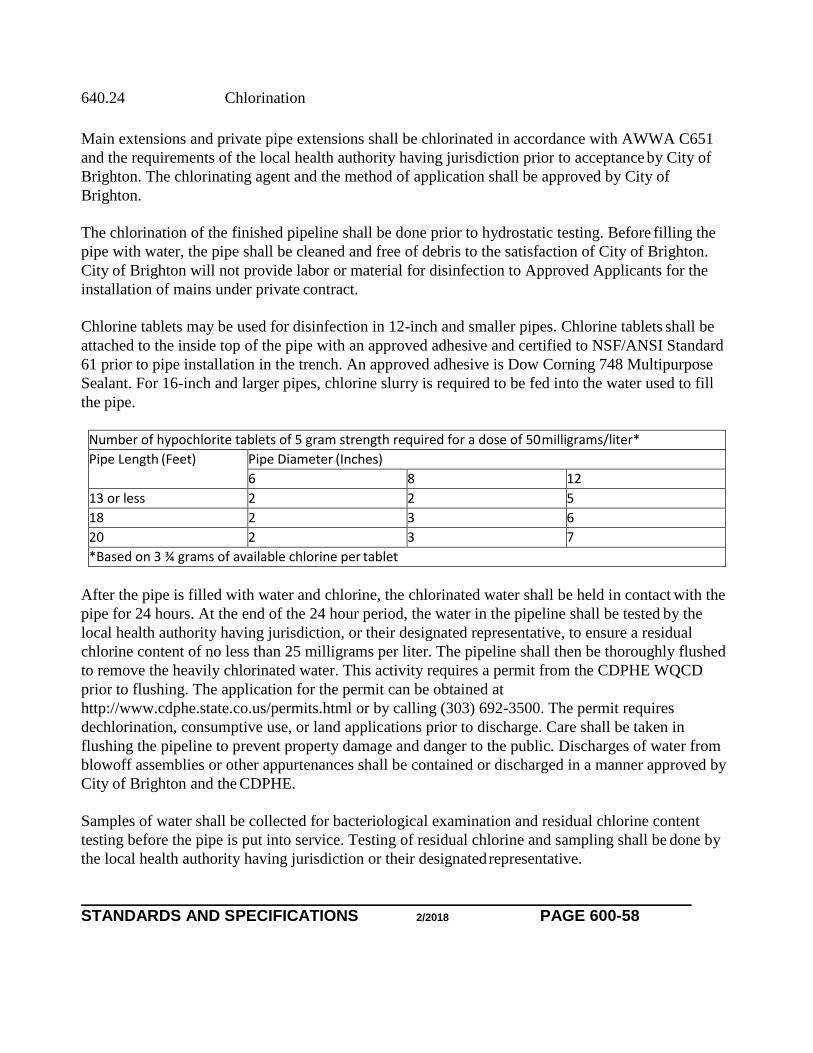
STANDARDS AND SPECIFICATIONS 2/2018 PAGE 600-58
640.24 Chlorination
Main extensions and private pipe extensions shall be chlorinated in accordance with AWWA C651
and the requirements of the local health authority having jurisdiction prior to acceptance by City of
Brighton. The chlorinating agent and the method of application shall be approved by City of
Brighton.
The chlorination of the finished pipeline shall be done prior to hydrostatic testing. Before filling the
pipe with water, the pipe shall be cleaned and free of debris to the satisfaction of City of Brighton.
City of Brighton will not provide labor or material for disinfection to Approved Applicants for the
installation of mains under private contract.
Chlorine tablets may be used for disinfection in 12-inch and smaller pipes. Chlorine tablets shall be
attached to the inside top of the pipe with an approved adhesive and certified to NSF/ANSI Standard
61 prior to pipe installation in the trench. An approved adhesive is Dow Corning 748 Multipurpose
Sealant. For 16-inch and larger pipes, chlorine slurry is required to be fed into the water used to fill
the pipe.
Number of hypochlorite tablets of 5 gram strength required for a dose of 50 milligrams/liter*
Pipe Length (Feet) Pipe Diameter (Inches)
6 8 12
13 or less 2 2 5
18 2 3 6
20 2 3 7
*Based on 3 ¾ grams of available chlorine per tablet
After the pipe is filled with water and chlorine, the chlorinated water shall be held in contact with the
pipe for 24 hours. At the end of the 24 hour period, the water in the pipeline shall be tested by the
local health authority having jurisdiction, or their designated representative, to ensure a residual
chlorine content of no less than 25 milligrams per liter. The pipeline shall then be thoroughly flushed
to remove the heavily chlorinated water. This activity requires a permit from the CDPHE WQCD
prior to flushing. The application for the permit can be obtained at
http://www.cdphe.state.co.us/permits.html or by calling (303) 692-3500. The permit requires
dechlorination, consumptive use, or land applications prior to discharge. Care shall be taken in
flushing the pipeline to prevent property damage and danger to the public. Discharges of water from
blowoff assemblies or other appurtenances shall be contained or discharged in a manner approved by
City of Brighton and the CDPHE.
Samples of water shall be collected for bacteriological examination and residual chlorine content
testing before the pipe is put into service. Testing of residual chlorine and sampling shall be done by
the local health authority having jurisdiction or their designated representative.

STANDARDS AND SPECIFICATIONS 2/2018 PAGE 600-59
640.25 Hydrostatic Testing
Newly installed water mains and firelines shall be hydrostatically tested. Hydrostatic tests shall not
be made on any portion of the pipeline until field placed concrete has had adequate curing time as
defined for kickblocks.
City of Brighton shall be notified 24 hours in advance of testing. Testing shall be made in the
presence of City of Brighton.
Only the following methods are acceptable for supplying potable water for hydrostatic testing:
A. Water may be taken from a nearby pressurized water source that was previously
chlorinated, tested, and accepted, such as a fire hydrant.
B. Water may be delivered to the site in a state licensed chlorinated water truck having a
minimum capacity of 300 gallons. The water truck shall be used exclusively for the
transportation of potable water.
C. Any previously tested, chlorinated, and accepted water main that is pressurized and is to
serve the new main extension may be tapped on the pressurized side of the closed valve.
The method of supplying water and the source of water for hydrostatic testing must be certified and
approved by City of Brighton. The use of barrels, sanitary or otherwise, to supply water for
hydrostatic testing is prohibited.
City of Brighton will furnish the calibrated meter for testing but will not supply the pump. The
pipeline shall be properly backfilled and in a state of readiness for testing. Bulkheads, pumps, taps,
and appurtenances necessary to fill the pipeline and maintain the required pressure shall be in place
and the pipeline filled with water. The test pressure of 150 psi shall then be applied to the pipeline
by means of a continuously operating pump that is equipped with a bypass valve for pressure
regulation. The pipeline shall be filled at a rate that does not cause surges and does not exceed the
rate at which air can be released. Air in the line shall be properly purged. Where blowoffs or
hydrants are not available or are not effective in purging air from the line, City of Brighton will
require a tap to purge the line. The location and the size of the tap to be used is at City of Brighton's
discretion.
While the test pressure is maintained, an examination shall be made of the pipeline and any leaks
located and repaired. Pipe or fittings found to be faulty shall be removed and replaced. Leakage is
not allowed through the bonnet of the line valve. A valve leaking through the bonnet may be
repaired in place or removed and replaced. Cutting and replacement of pavement as well as
excavation and backfilling may be necessary when locating and repairing leaks discovered during
pressure testing.

STANDARDS AND SPECIFICATIONS 2/2018 PAGE 600-60
After visible leaks are stopped, the full test pressure shall be maintained for 1 continuous hour.
Allowable leakage for each section between line valves shall not exceed the following leakage rates
for 4 through 20-inch distribution and transmission mains:
Allowable Leakage Per Hour
Pipe Size (Inches) Gallons Per 1,000 Feet of Pipe
4 0.33
6 0.50
8 0.66
12 0.99
16 1.32
20 1.66
Should testing show a leakage rate in excess of the rates shown, the pipeline will not be accepted.
The pipeline shall be repaired, rechlorinated, and retested until it meets test requirements.
640.26 Acceptance and Release for Taps
A main will be accepted by City of Brighton and released for taps when the following conditions are
met:
A. Installation: The main and appurtenances are installed to the satisfaction of City of
Brighton and pertinent notes and measurements made.
B. Tests: The following tests are passed and the test outcomes provided to City of Brighton:
1. A chlorination test and any other tests required by the local health authority having
jurisdiction.
2. A compaction test indicating the trench backfill meets City of Brighton requirements
performed under the direction of a PE.
3. A hydrostatic test.
4. A valve and valve box inspection.
640.27 Blowoff Assembly
In installations where the main is to be permanently dead-ended, such as a cul-desac, a blowoff
assembly shall be installed. Where the main is to be temporarily dead-ended, such as the boundary of
a subdivision filing, a blowoff shall be installed unless a fire hydrant, which can serve additionally as
a blowoff, is located at the main's temporary end. The blowoff shall be

STANDARDS AND SPECIFICATIONS 2/2018 PAGE 600-61
installed at a right angle to the main and on the side that allows the water to drain away from the
main to the nearest gutter.
The standard required blowoff assembly for 12-inch and smaller mains shall be 2- inches. Under
special conditions, such as a long run with only a few taps, a nonstandard blowoff larger than 2-
inches may be required.
The standard required blowoff for 16-inch and larger ductile iron pipe shall be a 6- inches.
640.28 Sewer Crossings
When water mains or associated piping cross over or under a sanitary or storm sewer constructed of
vitrified clay or concrete pipe, the sewer shall be replaced or protected as shown on plans during the
course of installation, as described below, or as otherwise directed by City of Brighton.
When the sewer is 15-inches or less in diameter and crosses over the water mains or associated
piping and protection is not otherwise shown on plans, where applicable, the sewer shall be
replaced with polywrapped Special Thickness Class 50 ductile iron pipe manufactured in
accordance with AWWA C151 or Type PSM SDR 35 PVC sewer pipe manufactured in accordance
with ASTM D 3034. Reconnections to the existing sewer pipe shall be made with watertight,
flexible couplings approved by City of Brighton and the authority having jurisdiction over the sewer
being replaced. Drains that exist under the sewer shall be restored in a manner that prevents any
flow from entering the trench.
When the sewer is greater than 15-inches in diameter, necessary precautions shall be taken to
protect the sewer during the installation of water mains or associated piping. Drains that exist under
the sewer shall be restored in a manner that prevents any flow from entering the trench.
When water mains or associated piping cross over the sewer with less than 2 feet of clearance
between the pipes, the sewer shall be encased with a minimum of 6 inches of concrete from the
springline to 6 inches above the top of the sewer. The encasement shall extend along the centerline
of the sewer for a minimum of 1 foot beyond the OD of the water main or associated piping at each
end of the encasement.
In addition, when water mains or associated piping cross under a sewer, the bedding material shall
be replaced around the sewer to a point at least 1 foot above the top of the sewer pipe for sewers 15-
inches in diameter and smaller, and to at least springline for sewers larger than 15- inches in
diameter. Bedding material shall be thoroughly compacted and consolidated to support the sewer.
Water mains shall not be placed closer than 18 inches, as measured from the outside bottom of the
sewer pipe to the top of the water pipe.

STANDARDS AND SPECIFICATIONS 2/2018 PAGE 600-62
A sewer may not be cut without the express consent of the authority having jurisdiction over the
sewer.
640.29 Horizontal Directional Drilling
With the approval of City of Brighton, Horizontal Directional Drilling (HDD) may be used as a
method of installing PVC or ductile iron distribution mains. HDD is a trenchless methodology of
installing pipe that consists of three primary stages: piloting (drilling of a pilot hole), reaming (pilot
hole enlargement), and pull-back (installation of the carrier pipe).
The directional drilling machine generally consists of a hydraulically powered system that rotates
and pushes a hollow drill pipe into the ground at a variable angle while delivering a pressurized
fluid mixture to a guidable boring head.
Prior to any work, the Contractor shall submit to City of Brighton a pilot bore plan with the vertical
scale of 1” = 2’ and horizontal scale of 1” = 20’. The plan shall include the bore entry point and
angle, bore exit point and angle, ground line, deflection and radiuses of the pilot bore, and existing
utilities with minimum vertical and horizontal clearances. The Contractor shall confirm the
alignment and elevation of critical utilities by potholing, using vacuum excavation, or other suitable
excavation method.
The Contractor shall utilize a self-contained, closed, drilling fluid mixing system of sufficient size
to mix and deliver drilling fluid (composed of bentonite clay, potable water, and appropriate
additives) to lubricate the cutting head during the drilling operation and stabilize the reamed bore
path prior to and during pull-back.
An electronic walkover tracking system shall be used to provide a continuous and accurate
determination of the location of the drill head during the drilling operation. It shall enable the driller
to guide the drill head by providing real-time feedback regarding the azimuth (horizontal direction)
and inclination (vertical direction) of the tool face. Readings shall be recorded every 10 feet, plotted
on a scaled drawing, and made available to City of Brighton. City of Brighton will approve the
location of the pilot hole prior to the reaming of the hole.
The bore hole diameter shall be increased to 1.2 to 1.5 times the outside diameter of the largest part
of the carrier pipe to accommodate the pull-back operation. The type of hole opener or back reamer
used shall be chosen by the Contractor with regard to the types of subsurface conditions identified
during the pilot hole drilling operation. The open bore hole shall be stabilized by bentonite drilling
slurry that is pumped though the inside diameter of the drill pipe and through openings in the
reamer.
The carrier pipe shall be assembled according to the manufacturer’s specifications and installed
using the cartridge or the assembled-line methods. The cartridge assembly method assembles

STANDARDS AND SPECIFICATIONS 2/2018 PAGE 600-63
individual sections of pipe in a secured entry and assembly pit. The assembled-line method consists
of the preassembly of multiple pieces of pipe with a subsequent pulling installation into the bore
hole as a long pipe string. For both methods, a pulling eye shall be attached to the pulling head on
the lead stick of pipe that in turn shall be attached to a swivel on the end of the drill pipe. The end
of the pipe shall be sealed to prevent contamination during the pull-back operation.
Tracer wire or polyethylene encasement, as required for the particular type of carrier pipe, shall be
adequately secured to the pipe prior to the pull-back operation. The Contractor should follow the
manufacturer’s recommendations regarding the installation of polyethylene encasement, which
includes making the final overlap opposite to the direction of the pull. The carrier pipe shall be
adequately supported as it enters the bore hole to minimize forces on the pipe during pull-back.
Pull-back shall be carried out in a continuous manner until the pipe reaches the original entry side
of the bore. The manufacturer’s recommendations regarding bend radius and tensile strength shall
be followed. Following pullback, the Contractor shall allow the pipe to
achieve mechanical and thermal equilibrium with its surroundings prior to cutting it at either end.
The Contractor is responsible for drilling fluid disposal and other restoration and shall comply with
regulations regarding the proper disposal of drilling fluid. Cleaning, flushing, and hydrostatic
testing of the pipe shall be conducted as specified in these Standards.
The Contractor shall provide an as-built plan and profile drawing to City of Brighton based on
electronic walkover system readings showing the actual location, horizontally and vertically, of the
installation.
640.30 Pipe Bursting
Pipe bursting may be used as a method of replacing distribution mains with the written approval of
City of Brighton. Pipe bursting is a trenchless methodology that involves the insertion of a conical
shaped static bursting head into the pipe to fracture the pipe, thereby displacing the pipe fragments
outward as the new replacement main is pulled in to replace the existing pipe.
640.30.01 Equipment
Static pipe bursting equipment includes the bursting head, pulling machine, segmented pulling rods,
hydraulic power unit and associated restraint, and attachment equipment. The bursting head system
shall be designed and manufactured to force its way through the existing pipe by fragmenting the
pipe, pushing the fragments into the surrounding soil, and allowing for the pulling of the
replacement pipe into place.
The bursting head system shall be conical in shape and center in the pipe. It shall fracture the pipe
by applying radial pressure and expanding the surrounding soil and the fragments to the proper size
to accept the replacement pipe. The pull head to which the replacement pipe is attached shall not be
used to expand or otherwise increase the diameter of the existing

WATER SUPPLY FACILITIES SECTION 600
STANDARDS AND SPECIFICATIONS 2/2018 PAGE 600-0
fragmented pipe. The pull head shall utilize a positive through-bolt design assuring a smooth
wall against the pipe cross-section.
Pulling rods shall be segmented with snap lock connections. Cutting wheels shall be utilized to
assist in the demolition and fragmenting of the pipe. The system must maintain automatic thrust
and pull-back and be capable of
pulling from either side of the bursting head system.
640.30.02 Pipe
Pipe utilized for pipe bursting shall be fusible PVC pipe.
640.30.03 Installation
Existing underground utilities shall be positively identified. Exposure shall be made of facilities
located within an envelope of possible impact as a result of the pipe bursting operation.
Temporary water service to customers affected by outages as a result of the pipe bursting
operation shall be as approved by City of Brighton.
Service connections to the pipe being replaced shall be removed. Access pit excavation at the
point of insertion of the fusible PVC pipe shall provide for a pipe radius greater than that
recommended by the PVC pipe manufacturer.
Fusible PVC pipe shall be supported on rollers and shall not contact paving, grass, or earth
during the fusion process and staging for insertion.
Tracer wire, as approved by City of Brighton, shall be attached to the pulling head and installed
along the pipe.
Immediately following the completion of the pipe bursting operation, the pipe shall be pushed
back toward the insertion point until a small amount of movement is realized at the insertion
point.
650.00 MATERIAL SPECIFICATIONS
650.01 General
City of Brighton shall follow the Denver Water Material Specifications except as noted herein.