section 5600 12-2005
TRANSCRIPT
Division VSection 5600
Storm Drainage Systems& Facilities

This page intentionally left blank
56-1
DIVISION V
CONSTRUCTION AND MATERIAL SPECIFICATIONS
SECTION 5600 STORM DRAINAGE SYSTEMS AND FACILITIES
Approved and Adopted this 15th day of February 2006
Kansas City Metropolitan ChapterAmerican Public Works Association
SECTION 5600 STORM DRAINAGE SYSTEMS AND FACILITIES................................1
SECTION 5601 GENERAL................................ ....................................................................15601.1 Introduction ................................................................................................................15601.2 Definitions................................................................................................ ..................25601.3 General Requirements and Applicability......................................................................65601.4 Existing Drainage System ................................ ...........................................................75601.5 System Types and Applications................................ ...................................................75601.6 Waivers ....................................................................................................................105601.7 Other Requirements ................................ ..................................................................105601.8 Levels of Service................................................................................................ .......11
SECTION 5602 HYDROLOGY ...........................................................................................155602.1 Scope ......................................................................................................................155602.2 Computation Methods for Runoff..............................................................................155602.3 Runoff Coefficients...................................................................................................175602.4 Rainfall Mass ...........................................................................................................195602.5 Unit Hydrographs .....................................................................................................205602.6 Rainfall Intensity .....................................................................................................205602.7 Time of Concentration and Lag Time................................................................ ........205602.8 Hydrograph Routing ................................................................ .................................215602.9 Calibration and Model Verification ...........................................................................21
SECTION 5603 HYDRAULICS ...........................................................................................225603.1 Hydraulic Calculations for Pipes, Culverts, and Open Channels .................................225603.2 Analysis of Systems by Computer Models................................ .................................25
SECTION 5604 INLETS, MANHOLES, AND JUNCTION BOXES .................................265604.1 Inlet Design ..............................................................................................................26
5604.2 Gutter Flow ..............................................................................................................265604.3 Gutter Capacity ................................................................................................ ........275604.4 Freeboard Requirements............................................................................................275604.5 Inverts and Pipes................................................................................................ .......285604.6 Street Grade on Vertical Curves................................................................ ................285604.7 Loading Conditions for Structures.............................................................................28
SECTION 5605 NATURAL STREAMS...............................................................................295605.1 Scope .......................................................................................................................295605.2 Natural Stream Benefits and Characteristics..............................................................295605.3 Stream Preservation and Buffer Zones................................................................ .......295605.4 In Stream Construction - General Requirements.........................................................305605.5 Stream Assessment ...................................................................................................315605.6 Discharge Outfalls ....................................................................................................345605.7 Culverts, Bridges, and Above Grade Crossings ..........................................................365605.8 Below Grade Stream Crossings ................................ .................................................365605.9 Grade Control ...........................................................................................................375605.10 Floodplain Fills................................................................................................ .......375605.11 Flood Control Projects ............................................................................................385605.12 Bank Stabilization Projects......................................................................................385605.13 Stream Restoration................................ ..................................................................415605.14 Comprehensive Stream Management ................................................................ .......41
SECTION 5606 ENCLOSED PIPE SYSTEMS ..................................................................435606.1 Easements ................................................................................................ ................435606.2 Capacity ................................ ..................................................................................435606.3 Pressure Flow ................................ ..........................................................................435606.4 Energy Dissipation....................................................................................................435606.5 Velocity Within the System.......................................................................................455606.6 Loading ....................................................................................................................45
SECTION 5607 ENGINEERED CHANNELS.....................................................................465607.1 Introduction ..............................................................................................................465607.2 Easements ................................................................................................ ................465607.3 Freeboard ................................................................................................ ................465607.4 Channel Linings................................................................................................ ........465607.5 Lining Material................................................................ .........................................475607.6 Side Slopes ...............................................................................................................475607.7 Alignment Changes ...................................................................................................485607.8 Vertical Wall Channels .............................................................................................485607.9 Energy Management ................................................................ .................................48
SECTION 5608 STORMWATER DETENTION AND RETENTION...............................495608.1 Scope ......................................................................................................................495608.2 Easements ................................................................................................ ................495608.3 Maintenance and Continued Performance ..................................................................49
5608.4 Performance Criteria ................................................................ .................................505608.5 Detention Methods ....................................................................................................525608.6 Required Submittals................................ ..................................................................535608.7 Additional Requirements ...........................................................................................54
SECTION 5609 PLAN REQUIREMENTS ................................ .........................................555609.1 Scope ......................................................................................................................555609.2 General ....................................................................................................................555609.3 Type of Sheets in Plans .............................................................................................555609.4 Sheet Sizes ...............................................................................................................555609.5 Scales.......................................................................................................................555609.6 Required Information for Title Sheet ................................ .........................................565609.7 Required Information for General Layout Sheet .........................................................565609.8 Required Information for Plan and Profile Sheets.......................................................575609.9 Cross-section sheets................................ ..................................................................575609.10 Drainage Area Map ................................................................ ................................585609.11 Standard and Special Detail Sheets ..........................................................................585609.12 Traffic Control Plans ..............................................................................................585609.13 Temporary Erosion Control Plan Sheets ..................................................................585609.14 Grading Plan Sheets ................................................................ ................................585609.15 Property Line and Easement Sheets ................................ .........................................59
TABLES5602-1 Documented Stream Flows................................................................ ........................635602-2 Design Aide for Calculating Rainfall Intensity...........................................................645603-1 Manning’s Roughness Coefficient .............................................................................655603-2 Head Loss Coefficient...............................................................................................665605-1 Critical Shear Stresses for Channel Materials ............................................................675605-2 Channel Condition Scoring Matrix ............................................................................695605-3 Characteristics of Certain Plants for Bio-Engineering................................ ................725606-1 Permissible Shear Stresses for Lining Material..........................................................735606-2 Classification of Vegetal Covers as to Degree of Retardance .....................................745606-3 Energy Dissipation Countermeasures ................................................................ ........75
FIGURES5601-1 Guide to Stormwater Management for Site Development ...........................................795602-1 Hundred YearDischarges per Kansas Rural Regression (2000)and Gage Estimates ..............................................................................................................805602-2 Hundred Year Discharges per Missouri Rural Regression and GageEstimates..............................................................................................................................815602-3 Documented Extreme Streamflows as Discharges per Unit Drainage Area .................825602-4 Documented Extreme Streamflows as Absolute Discharges ................................ .......835602-5 Intensity Duration Frequency Chart...........................................................................845602-6 Overland Flow Time Nomogram...............................................................................855602-7 Channel Flow Time Nomogram ................................................................ ................865603-1 Headwater Depth for Box Culverts with Inlet Control................................ ................87
5603-2 Headwater Depth for Concrete Pipe Culverts with Inlet Control.................................885603-3 Headwater Depth for Oval Concrete Pipe Culverts with Inlet Control ........................895603-4 Headwater Depth for Oval Concrete Pipe Culverts with Inlet Control ........................905603-5 Headwater Depth for C.M. Pipe Culverts with Inlet Control ......................................915603-6 Headwater Depth for C.M. Pipe Arch Culverts with Inlet Control..............................925603-7 Headwater Depth Circular Pipe Culverts with Beveled Ring Inlet Control ..................935603-8 Head for Concrete Pipe Culverts Flowing Full (n = 0.012) ................................ ........945603-9 Head for Concrete Box Culverts Flowing Full (n = 0.012).........................................955603-10 Head for Oval Concrete Pipe Culverts Flowing Full (n = 0.012) ..............................965603-11 Head for Standard C.M. Pipe Culverts Flowing Full (n = 0.024) .............................975603-12 Head for Standard C.M. Pipe Arch Culverts Flowing Full (n = 0.024).....................985603-13 Head for Structural Plate C.M. Pipe Culverts Flowing Full .....................................995603-14 Head for Structural Plate C.M. Pipe Arch Culverts Flowing Full ...........................1005604-1 Curb Inlets Minimum Hydraulic Dimensions ...........................................................1015604-2 – 5604-19 Curb Inlet Intercept Ratio Charts............................................................1055604-20 Nomograph for Flow in Triangular Channels.........................................................1145604-21 Capacity of Curb Opening Inlet at Low Point in Grade..........................................1155605-1A Typical Stream Characteristics A .........................................................................1165605-1B Typical Stream Characteristics B .........................................................................1165605-1C Typical Stream Characteristics C .........................................................................1175605-2A Natural Channel Assessment ................................................................................1185605-2B Natural Channel ...................................................................................................1195605-3 Grade Control Structure..........................................................................................1205606-1 Hydraulic Elements of Circular Conduits ................................................................1215606-2 Permissible Shear Stresses for Non-Cohesive Soils ..................................................1225606-3 Permissible Shear Stresses for Cohesive Soils .........................................................1235608-1 Annual Sediment Storage................................ ........................................................124
REFERENCES ....................................................................................................................125

5600 5601.1
56-1
DIVISION VDESIGN CRITERIA
SECTION 5600 STORM DRAINAGE SYSTEMS AND FACILITIES
SECTION 5601 GENERAL
5601.1 Introduction:
These criteria provide uniform procedures for designing and checking the design ofstorm drainage systems under the rainfall and land characteristics typical of theKansas City Metropolitan Area. This manual generally focuses on water quantityconcerns including: conveyance, flow rates, and construction design parameters ofstormwater systems. For an in-depth discussion of water quality design standards andBest Management Practices (BMPs) for the Kansas City Metropolitan area see the“Mid-America Regional Council and American Public Works Association; Manual forBest Management Practices for Stormwater Quality”.
Federal law requires that “Waters of the United States may be disturbed only afterpermission is received from the City/County and permitted by the U.S. Army Corps ofEngineers, if applicable. A jurisdictional determination by the U.S. Army Corps ofEngineers shall be obtained prior to beginning design.” Besides federal guidelines,specific criteria have been developed and are applicable to the types of drainagesystems and facilities ordinarily encountered in local urban and suburban areas. Otherspecial situations may be encountered that require added criteria or more complextechnology than included herein such as maintaining or improving water quality. Anydesign procedure conforming to current accepted engineering practice may be used forthe design of storm drainage systems in lieu of the computation methods presented inthis manual, providing equivalent results are obtained and have been approved by theCity/County Engineer. Drainage systems for all developments shall be designedassuming ultimate or built-out land-use conditions. The decision flowchart in Figure5601-1, “Guide to Stormwater Management for Site Development”, shall be used todetermine the appropriate runoff controls.

5601.2 5601.2
56-2
5601.2 Definitions:
Best Management Practice (BMP): Stormwater management practice used to preventor control the discharge of pollutants to water of the U.S. BMPs may includestructural or non-structural solutions, a schedule of activities, prohibition of practices,maintenance procedures, or other management practices. For a comprehensivediscussion on BMPs refer to the “Mid-America Regional Council and AmericanPublic Works Association; Manual for Best Management Practices for StormwaterQuality”.
City/County: The municipality or body having jurisdiction and authority to govern.
City/County Engineer: The municipal or county public works official or body havingjurisdiction and authority to review and approve plans and designs for storm drainagesystems.
Design Storm: The combination of rainfall depth, duration, and distribution of ahypothetical rainfall event with a given likelihood of occurring in any year.
Channel Lining: Includes any type of material used to stabilize the banks or bed of anengineered channel including, but not limited to, vegetation.
Detention Facility: A storm water management facility controlling storm waterrunoff from a site or watershed. The allowable runoff specified for detention facilitiesin Section 5608 is intended to manage maximum storm water release rates to minimizeflooding and does not address impacts on downstream erosion, water quality or theenvironment.
Detention Storage: The volume occupied by water above the level of the principalspillway crest during operation of a stormwater detention facility.
Developer: Any person, partnership, association, corporation, public agency, orgovernmental unit proposing to or engaged in "development".
Development: Any activity, including subdivision, that alters the surface of the land tocreate additional impervious surfaces, including, but not limited to, pavement,buildings, and structures. Refer to Section 5601.3 for applicability.
Easement: Authorization by a property owner for the use by another for a specifiedpurpose, of any designated part of the property.
Emergency Spillway: A device or devices used to discharge water under conditions ofinflow that exceed the design outflow from the primary spillway detention facility. Theemergency spillway functions primarily to prevent damage to the detention facility thatwould permit the sudden release of impounded water.

5601.2 5601.2
56-3
Engineer: See ‘Registered Professional Engineer’.
Engineered Channel: An open drainage channel that has been explicitly designed toconvey stormwater runoff in accordance with Section 5607 or as approved by theCity/County engineer.
FHWA: Federal Highway Administration.
Floodplain: A relatively level surface of stratified alluvial soils on either side of awatercourse that is inundated during flood events.
Freeboard: The difference in elevation between the top of a structure such as a damor open channel and the maximum design water surface elevation or high water mark.It is an allowance against overtopping by waves or other transient disturbances.
Impact Stilling Basin: A device that dissipates energy by allowing flowing water tostrike a stationary surface therefore producing turbulence and energy loss. .
Impervious Surface: A surface that prevents the infiltration of stormwater.
Improved Channel: Any channel changed by grading or the construction of liningmaterials as approved by the City/County Engineer.
Incision: Adjustment of the channel bed elevation downwards, typically in response tosome type of disturbance.
Increased Runoff: Increase in volume or peak flow of stormwater runoff.
Meander amplitude: The linear distance between the apex of one meander and theapex of the next meander in a naturally curving stream.
Meander length: The length measured along the thalweg of one complete waveform.
Meander wavelength: The length of one complete waveform, measured as thestraight-line linear distance along the valley between two analogous points on awaveform.
Low-drop structures: A step pool energy dissipation structure typically constructedout of rock or concrete with a design vertical drop of 2 feet or less per step.
Natural Channel: Any waterway with the ability to self-form by virtue of having atleast one unfixed boundary. This includes drainage ways that may have beenpreviously disturbed but through inactivity over time have begun to reform one ormore characteristics of undisturbed streams.
5601.2 5601.2
56-4
Open Channel: A maintained earthen or lined waterway with an open water surfaceas approved by the City/County engineer.
Ordinary High Water Mark: A line on the bank established by the fluctuations ofwater and indicated by physical characteristics such as clear, natural line impressed onthe bank, shelving, changes in the character of soil, destruction of terrestrialvegetation, the presence of litter and debris, or other appropriate means that considerthe characteristics of the surrounding areas.
Owner: The owner of record of real property.
Point bars: Depositional features generally occurring on the inside of stream bendsand opposite cut banks.
Pools: A deep reach of a stream. The reach of a stream between two riffles; a smalland relatively deep body of quiet water in a stream or river.
Primary Outlet Works: A device such as an inlet, pipe, weir, etc., used to dischargewater during operation of a storage facility under the conditions of the 1% storm ormore frequent event.
Principal Stream: Stream Segments included in FEMA Flood Insurance Studieswhere the limits of the 1% floodplain and 1% base flood elevations have beendetermined.
Redevelopment: Remodeling, repair, replacement, or other improvements to anyexisting structure, facility, or site.
Registered Professional Engineer: A licensed engineer who is registered with andauthorized to practice engineering within the state of registration.
Riffles: Shallow rapids in an open stream, where the water surface is broken intowaves by obstructions such as natural channel armoring or bedrock outcrop wholly orpartly submerged beneath the water surface.
Sediment Storage: The volume allocated to contain accumulated sediments within adetention facility.
Site: A tract or contiguous tracts of land owned and/or controlled by a developer orowner. Platted subdivisions, industrial and/or office commercial parks, and otherplanned unit developments shall be considered a single site. This shall include phaseddevelopment where construction at a tract or contiguous tracts of land may occur inincrements.
Storm: A rainfall event used for design which is defined by the probability such anevent will be equaled or exceeded in any one year. When designing in according with
5601.2 5601.2
56-5
these criteria, the storm event probabilites used are: 1%, 2%, 4%, 10%, 50% and100%.
Storm Drainage System: All of the natural and man-made facilities andappurtenances such as ditches, natural channels, pipes, culverts, bridges, openimproved channels, swales, street gutters, inlets, and detention facilities which serve toconvey surface drainage.
Storm Water Detention Facility: Any structure, device, or combination thereof witha controlled discharge rate less than its inflow rate.
Swale: An engineered channel conveying stormwater from more than two lots;oftenthe swale is maintained by the property owner but an easement is required whenrequested by the City/County.
Thalweg: The deepest part of a channel cross-section. The dominant thread of streamflow creates the thalweg.
Tributary Area: All land draining to the point of consideration, regardless ofownership.
Watershed: All the land area that drains to a given point.
Waveform: A complete cycle of two channel bends in opposite directions.
Wet Detention Facility: A detention facility that is designed to include permanentstorage of water in addition to the temporary storage used to control discharge ratesfrom the facility.
5601.3 5601.3
56-6
5601.3 General Requirements and Applicability:
The design shall be accomplished under the direction of a Registered ProfessionalEngineer qualified in the field of stormwater design. The design shall be based on landuse in the tributary area as zoned, actually developed, or indicated by an adoptedfuture land use plan, whichever basis produces the greatest runoff.
This design criteria shall apply to all development, including subdivision, that altersthe surface of the land to create additional impervious surfaces, including, but notlimited to, pavement, buildings, and structures with the following exceptions:
A. Redevelopment, expansion, renovation, repair and maintenance activities listedbelow:
1. Additions to, improvements, and repair of existing single-family and duplexdwellings.
2. Remodeling, repair, replacement, or other improvements to any existingstructure or facility and appurtenances that does not cause an increased areaof impervious surface on the site.
3. Remodeling, repair, replacement or other improvements to any existingstructure or facility and appurtenances on sites smaller than two acres thatdoes not cause an increased area of impervious surface on the site in excess of10 percent of that previously existing.
4. Remodeling, repair, replacement, or other improvements to any existingstructure or facility and appurtenances that does not cause an increased areaof impervious surface on the site in excess of 10 percent of that previouslyexisting, provided the total impervious area of the site is less than 20 percentof the total land area of the site post construction. (See “Site Planning forUrban Stream Protection” provided by the “Center for Watershed Protection”for a discussion on imperviousness and it’s effect on watershed health;http://www.cwp.org/SPSP/TOC.htm ).
B. New construction meeting the following criteria:
1. Construction of any one new single family or duplex dwelling unit,irrespective of the site area on which the structure may be situated, providedthe total impervious area of the site is less than 20 percent of the total landarea of the site post construction.
2. Construction of any buildings, structures, and/or appurtenant service roads,drives, and walks on a site having previously provided stormwatermanagement, as defined in Section 5601.5 A4 as part of a larger unit of
5601.3 5601.3
56-7
development, OR a site previously relieved of stormwater managementrequirements.
5601.4 Existing Drainage System:
Existing drainage system component pipes, structures, and appurtenances within theproject limits may be retained as elements of an improved system providing:
A. They are in sound structural condition.
B. Their hydraulic capacity, including surcharge, is equal to or greater than thecapacity required by these criteria.
C. Easements exist or are dedicated to allow operation and maintenance.
Discharge from an existing upstream storm drainage system shall be computedassuming its capacity is adequate to meet the performance criteria listed in Section5601.8. The computed discharge shall be used to design the new downstream systemeven if the actual capacity of the existing upstream system is less.
5601.5 System Types and Applications:
A. General Guidelines: Natural channels are to be preserved to the maximum extentpracticable as site conditions permit. Design standards for natural channels areaddressed in Section 5605. Engineered channels, the next highest priority systemcomponent, shall be designated and coordinated with the design of building lotsand streets in accordance with the design criteria and performance standardsaddressed in section 5607.
To the maximum extent possible, drainage systems, street layout and grades, lotpatterns and placement of curbs, inlets and site drainage, and overflow swalesshall be concurrently designed in accordance with the design criteria andperformance standards set forth in this document. Curb and gutter may be omittedor modified where approved by the City/County Engineer and deemed feasible inconjunction with other stormwater management practices including water qualityBMPs.
Enclosed conveyance systems consisting of inlets, conduits, and manholes may beused to convey stormwater runoff where site conditions and open spacerequirements will not permit the use of natural or engineered channels. Whereused, such systems must be designed in accordance with design criteria andperformance standards addressed in section 5606.
Generally, a drainage system is engineered and constructed when the drainage areaexceeds 2 acres.

5601.3 5601.3
56-8
1. Open Systems: Where feasible, open systems consisting of open orengineered channels shall be used if all of the following design criteria and theconditions of Section 5601.8 are met:a. The channel slope is less than or equal to 5 percent or where appropriate
armoring techniques are used to prevent erosion.
b. The 100% storm velocity is less than or equal to 5 feet per second (fps) orwhere appropriate armoring techniques are used to prevent erosion.
c. When 60 feet or farther away from top of bank to any existing orproposed habitable building, regardless of system design capacity.
2. Enclosed Systems: Enclosed systems consisting of underground pipes,culverts, and similar underground structures shall be used to conveystormwater at all locations whenever one of the following design criteria andthe conditions of 5601.8 are met:
a. Where natural channels or open systems are not feasible per therequirements set forth in Section 5605 and Section 5601.5-A1
b. Within the right-of-way of streets with curbs, regardless of system designcapacity.
3. Overflow Systems: Each conveyance element of the stormwaterdrainage system (whether open, enclosed, or detention) shall include anoverflow element if the in-system capacity is less than the 1% stormflows. Overflow systems shall:
a. Be designed to route downstream any amount of the 1% storm exceedingthe in-system design capacity specified in Section 5601.8.
b. Include streets, engineered channels, redundant piping, spillways, parkinglots, drives or combinations thereof.
c. Limit the maximum water surface elevation generated by the 1% storm asspecified in Section 5601.8.
d. Conform to local standards regarding dedicated easements and/orrestricted uses for overflow systems; consult with the local authority forrequirements.
e. Be limited to the natural drainage basins, unless overflows transferred outof a natural drainage basin (e.g. a thoroughfare straight-graded through adrainage basin with a sump in another drainage basin) are added to theoverflows in the receiving drainage basin and the combined overflow stillmeets the criteria at 5601.5 A 3C

5601.5 5601.5
56-9
4. Stormwater Management: New development or redevelopment as defined inSection 5601.2 shall incorporate stormwater management measures to controlrunoff from the site. The allowable runoff is defined by the volume, timing,and peak rate of runoff and is dependent on the watershed characteristics.Allowable runoff may be limited by the need to minimize flood damage,prevent erosion, and/or minimize impacts to the ecology and water quality ofthe downstream drainage system.
Stormwater management for site development may include structural facilitiesand/or non-structural solutions. The Developer shall evaluate the sitedevelopment plan according to the flowchart in Figure 5601-1. This chartprovides decision criteria for determining the potential impacts of the site onthe watershed. Beginning with the dialog box in the upper left of the chart,check the requirements as indicated, then proceed to the next dialog box asdirected by the arrows. Determine the “yes” or “no” answer to the question ineach dialog box, and continue to next box to the right or below, according tothe answer. Where runoff controls are required, low-impact developmentpractices or, off-site control of runoff in addition to or instead of the standardwet or dry bottom basins may be used.
Flooding problems are defined as one or more of the following conditions:
a. Homes, buildings, or other structures downstream from a proposeddevelopment are flooded in a 1% or more frequent storm.
b. Flood damage problem areas caused by the 1% or more frequent stormhave been identified, or an engineering study indicates the proposeddevelopment would cause or increase such flooding.
c. Street flooding which is in excess of 5601.8(B) criteria or as defined bythe City/County.
To identify existing local flooding problems, the stormwater managementstudy for a development project shall include an analysis of the existingdownstream drainage system to the point the development’s land mass is lessthan 10% of the total watershed, unless waived by the City/County. TheCity/County may require additional analysis of the downstream drainagesystem to identify flooding problems, especially in sensitive areas or whereflooding has occurred downstream.
If flooding problems will occur, as defined above, runoff from thedevelopment shall be controlled, as specified in Section 5608,by limiting thestorm water release rates for the 1%, 10% and 100% storms to the

5601.5 5601.7
56-10
predevelopment peak flow rates for the 1%, 10% and 100% stormsrespectively.
Additionally, the City/County may require a study to verify downstreampredevelopment peak flow rates are not increased at specific downstreamlocations due to the development. Some communities may also establish morestringent release rates in sensitive watersheds.
5601.6 Waivers:
The Developer may submit a study by a registered professional engineer thatquantifies the problems and demonstrates that a waiver (exemption) of the requirementto provide stormwater management is appropriate. The City/County Engineer maywaive requirements to provide specific types of stormwater elements as follows:
A. Stormwater Management Facilities: Stormwater management facilities may bewaived and/or release rates other than those permitted by Section 5608 may beapproved by the City/County Engineer when the criteria in Figure 5601-1 havebeen met or when the development meets City/County-defined criteria for waivingflood control requirements.
B. Overflow Channels: In previously developed areas, requirements to provide for1% storm conveyance may be reduced by the City/County Engineer incircumstances where flood protection for the 1% storm is not reasonablyattainable due to the location of damageable improvements with respect to thedrainage system.
5601.7 Other Requirements:
Rules and regulations of other agencies also pertain to drainage systems which may ormay not complement these criteria. When conflicts are encountered, the more stringentcriteria shall govern.
The following agencies have jurisdiction over streams and/or drainage systems andoften require permits. Other regulations, permits and requirements may not be limitedto these agencies.
A. Federal Emergency Management Agency.
B. U.S. Army Corps of Engineers.
C. Missouri Department of Natural Resources.
D. Kansas Department of Agriculture.
E. Kansas Department of Health and Environment
5601.7 5601.8
56-11
F. Municipal Ordinances.
5601.8 Levels of Service:
Drainage systems shall be designed to meet all levels of service described below. Inaddition, natural streams include requirements specified inSection 5605.
A storm drainage system shall be provided that is capable of conveying the peakdischarge generated by the 1% storm. If the in-system capacity established in thissection is less the 1% storm peak discharge, then an overflow system as specified inSection 5601.5 -A-3 may provide the additional system capacity.
A. Protection of Property:
1. Property not reserved or designed for conveying storm water shall be protectedfrom frequent inundation:
a. When the total drainage area is less than 2 acres, protection may beprovided by following good lot grading practices or by one of theconveyances described below.
b. When the total drainage area is 2 acres or more, one of the followingconveyances must be used to convey the 10% storm:
1). Pipe system conveying the design storm under a regime of pressureflow with no overflow at inlets or manholes, or
2). An engineered open channel conveying the 10% storm at bank full
3). A street gutter
4). A natural stream
2. Buildings shall be protected from infrequent flooding by:
a. Providing a minimum of one-foot freeboard above the 1% storm stage, atany point along the drainage system, for openings in a building. For lakesand detention basins the 1% storm stage will be the water surface of flowthrough the emergency spillway. Where 10% storm flows are less than 8cfs, freeboard may be reduced to 6 inches.
b. Floodproofing a building below the 1% storm water surface elevation plusone foot of freeboard, in accordance with the current edition of theInternational Building Code or as required by the City/County. Where

5601.8 5601.8
56-12
10% storm flows are less than 8 cfs, freeboard may be reduced to 6inches.
c. Non habitable accessory buildings are sometimes provided less protectionby local City/County ordinances or policies. Consult the local authorityfor exceptions.
B. Protection for Streets:
1. Water spread in streets shall meet the requirements in Section 5604.2 for the 10%design storm. These values are intended to establish a standard of accessibility forthe widths (classes) of roadways listed during the 10% storm. When the localjurisdiction requires a higher standard for curb inlets, the conveyance systemconnected to the roadway must also meet that higher standard . If the roadwayconveyance system connects to an underground system with lesser capacity, thesystem must be constructed to allow the discharge of that excess capacity into theoverflow system.
2. Street Crossings. Concentrated flow not conveyed in the gutter system, shall beconveyed under streets to prevent vehicles from being swept from the roadway ininfrequent storms. These crossings may be bridges, culverts or undergroundsystems. A common practice is to construct the low point in the roadway so that itdoes not fall on the bridge or culvert. This practice protects the structure fromdamage in an overflow condition, but does not change this requirement. Crossingswill be designed to completely convey flood flows without street overtopping inaccordance with the following table:
Further, concentrated flow in excess of the minimum design storm may onlyovertop the roadway if the following conditions are met:
a. The span of the structure opening is less than 20 feet.
b. The peak stormwater runoff from the 1% storm is 250 cfs or less unless aguard fence is installed on the downstream side of the roadway.
Such overflow depths at low points in roadways during the 1% storm will belimited to 7 inches measured at the high point in the roadway cross section; exceptthat it also shall not exceed 14 inches at the deepest point in the roadway crosssection. Depths may be limited where necessary by reverse grading the
Street Classification Min. Design Storm CapacityArterial 2%Collector 4%Residential 10%Residential with open channel downstream 4%
5601.8 5601.8
56-13
downstream right of way area, by lengthening the vertical curve of the roadway,by reducing roadway crown, or by other similar means. Roadway overtoppingdepths shall be determined by integrating the broad crested wier formula acrossthe roadway profile. Each incremental flow can be determined by using theformula:
2/3Clhq
where:q is the flow for an increment of profile length (width of flow)l is the incremental widthC is a flow coefficient that shall not exceed 3.0h is the average depth of flow at each increment
The total flow Q is the sum of the incremental flows. Depthdeterminations can be made through an iterative process where successivedepths are chosen, Q is calculated for each depth and then compared tothe known Q at the overtopping point.
Overflow protection criteria provides additional accessibility criteria at majorstream crossings for emergency personnel, and provides the public with protectionagainst injury and property damage.
C. Downstream Impacts: The negative impacts of development on floodingproblems in the downstream system shall be mitigated through detention asspecified in Section 5601.5-A-4, or through other means approved by theCity/County.
1. Impacts on natural channels are regulated in Section 5605.
2. Communities that have adopted the recommended “Manual of BestManagement Practices (BMPs) for Stormwater Quality” should also mitigatethe negative impact of development on natural channels through theinstallation of water quality BMPs and closely adhere to practices specified inSection 5605 on natural channels.
D. Adjoining Property: State and Federal regulations often establish requirementsfor a storm drainage project that impacts adjoining property, especially when aproject causes a rise in water surface elevations. In addition to all Federal andState regulations the following shall be met:
1. Drainageways not designated a Special Flood Hazard Area (FEMA 1%Floodplain): Construction of a storm drainage system, including grading andfilling within a natural drainage way, requires agreement from adjoiningproperty owners if the work will cause a rise in the water surface elevation on

5601.8 5601.8
56-14
the adjoining property for the 1% storm. Agreement shall be consideredgranted by recording a document which reserves the affected property forinundation during the 1% storm, or by other means approved by theCity/County.
2. Drainageways designated a Special Flood Hazard Areas (FEMA 1%Floodplain) and City/County participates in the National Flood InsuranceProgram: When impacting adjoining properties, refer to the localcommunity’s adopted Floodplain Management Ordinance for anyrequirements, in addition to all current FEMA regulations.

5602 5602.2
56-15
SECTION 5602 HYDROLOGY
5602.1 Scope:
This section sets forth the hydrologic parameters to be used for computationsinvolving the definition of runoff mass and peak rates to be accommodated by thestorm drainage system. The methods to be used for calculating runoff mass and peakrates are intended for the design of drainage systems.
Refer to the “Mid-America Regional Council and American Public WorksAssociation; Manual for Best Management Practices for Stormwater Quality” fordesign methods and calculations of runoff water quality.
5602.2 Computation Methods for Runoff:
Runoff rates to be accommodated by each element of the proposed storm drainagesystem shall be calculated using the criteria of this section for land use runoff factors,rainfall, and system time. The following methods of computations are allowed:
A. Watersheds Less than 200 Acres: The Rational Method may be used to calculatepeak rates of runoff to elements of enclosed and open channel systems, includinginlets, when the total upstream area tributary to the point of consideration is lessthan 200 acres. The Rational Method is defined as follows:
KCiAQ , where
Q = Peak rate of runoff to system in cfs
C = Runoff coefficient as determined in accordance with Paragraph 5602.3
i = Rainfall intensity in inches per hour as determined in accordance withParagraph 5602.6
K = Dimensionless coefficient to account for antecedent precipitation as follows,except the product of KC shall not exceed 1.0.
Design Storm K
10% and more frequent 1.04% 1.12% 1.21% 1.25

5602.2 5602.2
56-16
B. Baseline Unit Hydrograph Method: The following computer implementations ofthe unit hydrograph method are acceptable for all watersheds:
1. SCS Technical Release No. 55 "Urban Hydrology for Small Watersheds",2nd Edition, June 1986.
2. SCS Technical Release No. 20 "Project Formulation - Hydrology", 2ndEdition, May 1983.
3. U.S. Army Corps of Engineers, Hydrologic Engineering Center - “HEC-1Flood Hydrograph Package”.
4. U.S. Army Corps of Engineers, Hydrologic Engineering Center - “HEC-HMSHydrologic Modeling System”, current version.
Copies of the above publications and micro-computer programs based thereon areavailable for purchase through National Technical Information Service, U.S.Department of Commerce, Springfield, VA 22161. Inputs for unit hydrographprocedures shall conform to the requirements of sections 5602.3 through 5602.8.
C. Kansas “Calibrated” Design Method: In lieu of the input parameters set forth insections 5602.3 through 5602.8, an alternative unit hydrograph method usingHEC-1 or HEC-HMS and conforming to recommendations based on researchconducted at the University of Kansas for gauged basins in Kansas (McEnroe andZhao, August 2001 and McEnroe and Gonzalez, July 2002) are allowed. Suchalternate procedures must use the appropriate total combinations of HEC-1hypothetical storm distributions, storm durations, antecedent moisture conditions,unit hydrograph peaking coefficients, and basin lag times as calibrated in theresearch. All other computations shall be given as required in this standard.Antecedent moisture condition adjustments shall be made only to the perviouscomponent of a watershed, direct conversion of composite antecedent moistureconditions is not appropriate.
D. Other Alternative Design Methods: Alternative design methods, includingcomputer models and Kansas “Calibrated” Design Method, may be employed solong as they produce runoff hydrographs to the system that are substantially thesame or more conservative than those calculated by the baseline method. To assessthe equivalence of such methods, the Engineer shall prepare estimates using boththe alternate design method and the baseline unit hydrograph method, and shallreport for every sub-basin the following data from both: peak flow rate, lag time,runoff volume, and equivalent curve number based on total storm precipitation anddirect runoff. Any discrepancy greater than 5% between the two models shall beclearly identified, and discrepancies that produce less conservative results shall bejustified. Testing of equivalence is not required if the alternative method has beenproven to the City/County engineer to be consistently more conservative than thebaseline unit hydrograph method or if the City/County Engineer has determined
5602.2 5602.3
56-17
that the alternative method is reliably more accurate or appropriate for the designcondition.
E. Regression Formulas: Rural regression formulas prepared by the U.S. GeologicalSurvey for Kansas (Rasmussen and Perry, 2000) and Missouri (Alexander andWilson, 1995) and urban regression formulas prepared for nationwide use (Sauer,Thomas, Stricker, and Wilson, 1983) or Missouri use (Becker, 1986), or theirsubsequent revisions, shall not be used as the sole input for project design, but areuseful tools for evaluating design models. Rural regression formulas shall be usedonly to represent rural or pre-development conditions when significant basinstorage does not exist. The Kansas rural regression formula produces substantiallymore conservative peak flow estimates than the Missouri equation and should beused unless specifically allowed otherwise by the City/County. For urbanwatersheds, the rural regression results can be used as inputs to the urbanregression formula, or a pre-development scenario of the basin model can bedeveloped to compare to the rural regression, and then physically realisticadjustments can then be made to impervious percentages, ground cover, basin lagtimes, and channel routing to produce the urban scenario. Figures 5602-1 and5602-2 show typical results for Kansas and Missouri, including a summary of thegauge data estimates used to derive the equations. Table 5602-1 and Figures5602-3 and 5602-4 present documented extreme stream flows in Kansas City andother areas. Engineers shall use caution in interpreting regression formula resultsand acknowledge the range of standard error and uncertainty of both the regressionformulas and the underlying gauge estimates.
5602.3 Runoff Coefficients:
A. Basis of Curve Number Coefficients. All Curve Number coefficients in thissection are values for Hydrologic Group “C” soils. For soils in other HydrologicGroups, equivalent SCS Curve Numbers can be found in SCS Technical ReleaseNo. 55. No soil disturbed by construction shall be assigned a Hydrologic Groupclassification of ‘A’ or ‘B’.
5602.3 5602.3
56-18
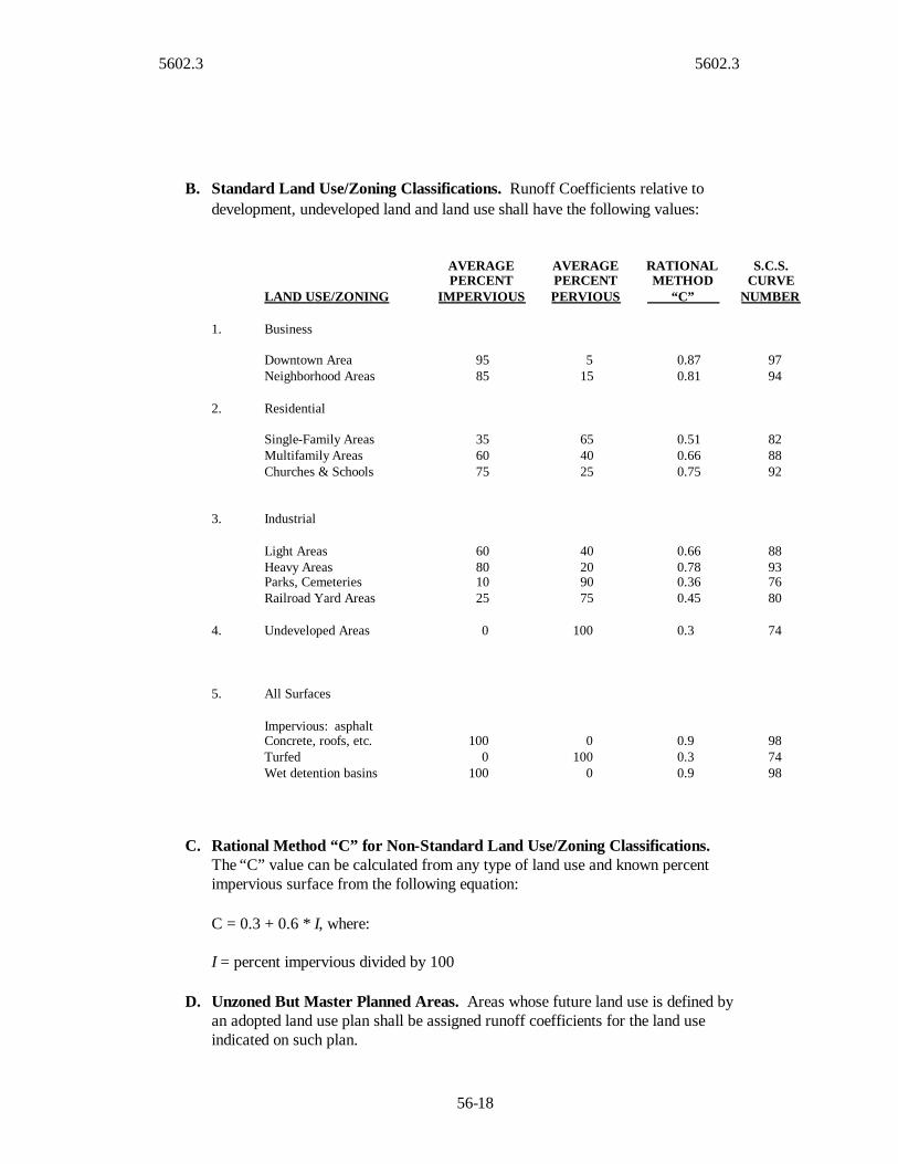
B. Standard Land Use/Zoning Classifications. Runoff Coefficients relative todevelopment, undeveloped land and land use shall have the following values:
LAND USE/ZONING
AVERAGEPERCENT
IMPERVIOUS
AVERAGEPERCENTPERVIOUS
RATIONALMETHOD
“C”
S.C.S.CURVE
NUMBER
1. Business
Downtown AreaNeighborhood Areas
9585
515
0.870.81
9794
2. Residential
Single-Family AreasMultifamily AreasChurches & Schools
356075
654025
0.510.660.75
828892
3. Industrial
Light AreasHeavy AreasParks, CemeteriesRailroad Yard Areas
60801025
40209075
0.660.780.360.45
88937680
4. Undeveloped Areas 0 100 0.3 74
5. All Surfaces
Impervious: asphaltConcrete, roofs, etc.TurfedWet detention basins
1000
100
0100
0
0.90.30.9
987498
C. Rational Method “C” for Non-Standard Land Use/Zoning Classifications.The “C” value can be calculated from any type of land use and known percentimpervious surface from the following equation:
C = 0.3 + 0.6 * I, where:
I = percent impervious divided by 100
D. Unzoned But Master Planned Areas. Areas whose future land use is defined byan adopted land use plan shall be assigned runoff coefficients for the land useindicated on such plan.
5602.3 5602.4
56-19
E. Agricultural and Unplanned Areas.
1. Existing Conditions: For purposes of determination of development impact,undeveloped areas whose current land use is agriculture (crops, pasture,meadow) shall be assigned a maximum of 0% impervious surface or amaximum Curve Number equivalent to good condition pasture, grassland orrange (C=0.30, CN=74).
2. Proposed Conditions: Undeveloped areas designated as agricultural or thoseareas for which no specific land use is indicated shall be assigned a minimumof 35% impervious surface for purposes of the design of storm drainagesystems (C=0.51, CN = 82).
F. Composite Coefficients. As an alternative to the above coefficients and for areasnot listed above (office parks, shopping centers, trailer parks, etc.), a compositerunoff coefficient based on the actual percentages of pervious and impervioussurfaces shall be used.
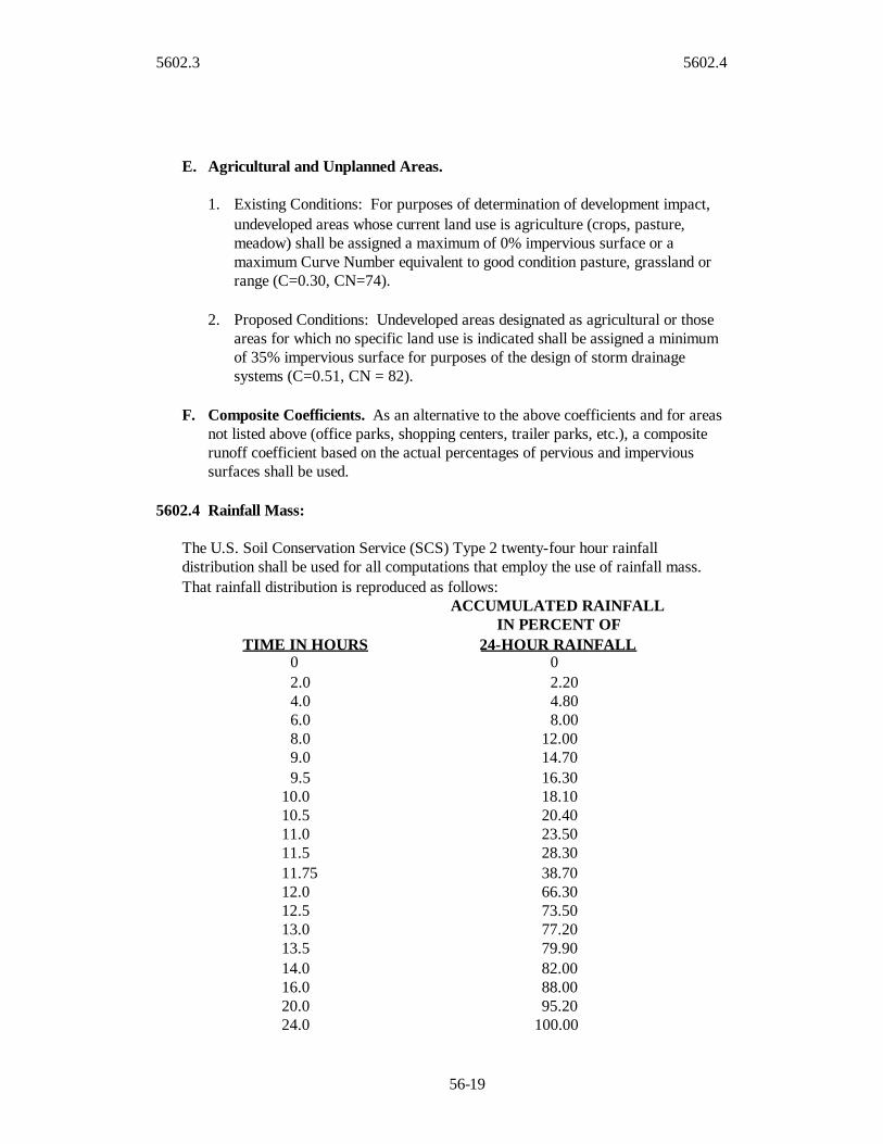
5602.4 Rainfall Mass:
The U.S. Soil Conservation Service (SCS) Type 2 twenty-four hour rainfalldistribution shall be used for all computations that employ the use of rainfall mass.That rainfall distribution is reproduced as follows:
TIME IN HOURS
ACCUMULATED RAINFALLIN PERCENT OF
24-HOUR RAINFALL0 02.0 2.204.0 4.806.0 8.008.0 12.009.0 14.709.5 16.30
10.0 18.1010.5 20.4011.0 23.5011.5 28.3011.75 38.7012.0 66.3012.5 73.5013.0 77.2013.5 79.9014.0 82.0016.0 88.0020.0 95.2024.0 100.00

5602.5 5602.7
56-20
5602.5 Unit Hydrographs:
The SCS Dimensionless Unit Hydrograph (either curvilinear or triangular) shall be thebasis for computation of runoff hydrographs.
5602.6 Rainfall Intensity:
Rainfall intensity shall be determined from Figure 5602.5 or Table 5602.2 using acalculated Time of Concentration.
5602.7 Time of Concentration and Lag Time:
Time of Concentration (TC) is equal to the overland flow time to the most upstreaminlet or other point of entry to the system, Inlet Time (TI), plus the time for flow in thesystem to travel to the point under consideration, Travel Time (TT).
TIC TTT
A. Inlet Time: TI shall be calculated by the following formula or determinedgraphically from Figure 5602-6, but shall not be less than 5.0 minutes nor greaterthan 15.0 minutes:
3/1
2/1)1.1(8.1S
DCTI where:
TI = Inlet Time in minutes
C = Rational Method Runoff Coefficient as determined in accordance withparagraph 5602.3
D = Overland flow distance parallel to slope in feet(100 feet shall be the maximum distance used for overland flow)
S = Slope of tributary area surface perpendicular to contour in percent.
B. Travel Time: TT shall be calculated as the length of travel in the channelizedsystem divided by the velocity of flow. Velocity shall be calculated by Manning'sequation assuming all system elements are flowing full without surcharge. Traveltime may be determined graphically from Figure 5602-7 in lieu of calculation.
To provide for future development when the upstream channel is unimproved, thefollowing table shall be used for calculating TT.

5602.7 5602.9
56-21
AVERAGE CHANNEL SLOPEPERCENT
VELOCITY INFT/SEC
< 2 72 to 5 10> 5 15
C. Lag Time: Lag Time (TL) is the calculated time between the maximum rainfallintensity of a storm and the point of maximum discharge on the outlet hydrograph.Lag Time is used instead of time of concentration for unit hydrograph models. Itshall be calculated as 3/5th the time of concentration (Tc) given by paragraph5602.7 (A and B).
5602.8 Hydrograph Routing:
Routing of hydrographs through storage elements or reservoirs shall be by modified-Puls level pool routing. Routing through channels shall be by the Muskingum-Cungemethod. If the detention effect of significant storage in channels behind roadwayembankments or culverts is to be modeled, the area impacted by the storage shall bemodeled as a reservoir, and the remainder of the channel modeled using Muskingum-Cunge. Such incidental detention shall not be used for design discharge estimatesunless allowed by the City/County and it can be reliably demonstrated that suchstorage will be maintained over the useful life of the proposed improvements.
5602.9 Calibration and Model Verification:
All design discharge estimates should be calibrated to the extent possible using reliablegauge data, high water marks, or historical accounts. Model results should beevaluated to verify that they are reasonably conservative as compared to observed dataand standard practice. Model calibration shall not be used to justify dischargeestimates that are lower than those provided by the baseline unit hydrograph method,unless unusual site specific factors justify, where the hydrologic impact of such factorsmust be thoroughly examined and documented. Engineers shall recognize thesignificant uncertainty associated with design discharge estimates and provideestimates that are reasonably conservative and protective of the public interest. Topermit model verification, discharge rates (expressed as absolute discharge ordischarge per acre of tributary area) shall be plotted relative to tributary area andcompared to regression formula results, gauge estimates, and/or known historicalextremes.

5603 5603.1
56-22
SECTION 5603 HYDRAULICS
5603.1 Hydraulic Calculations for Pipes, Culverts, and Open Channels:
A. Gravity versus Pressure Flow for Enclosed Systems: Two design philosophiesexist for sizing storm drains under the steady uniform flow assumption. The firstis referred to as open channel, or gravity flow design, in which the water surfacewithin the conduit remains open to atmospheric pressure. Pressure flow design, onthe other hand, requires that the flow in the conduit be at a pressure greater thanatmospheric. For a given flow rate, design based on open channel flow requireslarger conduit sizes than those sized based on pressure flow. While it may be moreexpensive to construct storm drainage systems designed based on open channelflow, this design procedure provides a margin of safety by providing additionalheadroom in the conduit to accommodate an increase in flow above the designdischarge. Under most ordinary conditions, it is recommended that storm drains besized based on a gravity flow criteria at full flow or near full. Pressure flow designmay be justified in certain instances. As hydraulic calculations are performed,frequent verification of the existence of the desired flow condition should be made.Storm drainage systems can often alternate between pressure and open channelflow conditions from one section to another (U.S. Department of TransportationFederal Highway Administration, 1996).
For gravity flow conditions, Manning’s formula shall be used as described below.
2/13/2486.1 SRAn
Q where:
Q = Discharge in cubic feet per second
A = Cross sectional area of flow in square feet
n = Roughness Coefficient (see Table 5603-1)
R = Hydraulic radiusPA
R in feet
S = Slope in feet per foot
P = Wetted perimeter in feet
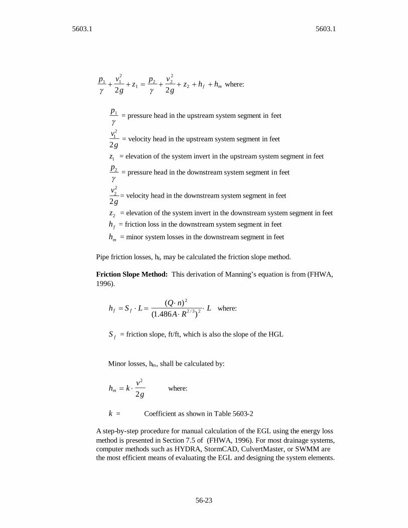
In closed conduits flowing under pressure flow, the energy grade line (EGL) willbe above the crown of the pipe. In this case, the Bernoulli equation shall be used tocalculate pipe capacity:
5603.1 5603.1
56-23
mf hhzg
vpz
gvp
2
222
1
211
22 where:
1p
= pressure head in the upstream system segment in feet
gv2
21 = velocity head in the upstream system segment in feet
1z = elevation of the system invert in the upstream system segment in feet
2p
= pressure head in the downstream system segment in feet
gv2
22 = velocity head in the downstream system segment in feet
2z = elevation of the system invert in the downstream system segment in feet
fh = friction loss in the downstream system segment in feet
mh = minor system losses in the downstream segment in feet
Pipe friction losses, hf, may be calculated the friction slope method.
Friction Slope Method: This derivation of Manning’s equation is from (FHWA,1996).
LRA
nQLSh ff
23/2
2
)486.1()(
where:
fS = friction slope, ft/ft, which is also the slope of the HGL
Minor losses, hm, shall be calculated by:
gv
khm 2
2
where:
k = Coefficient as shown in Table 5603-2
A step-by-step procedure for manual calculation of the EGL using the energy lossmethod is presented in Section 7.5 of (FHWA, 1996). For most drainage systems,computer methods such as HYDRA, StormCAD, CulvertMaster, or SWMM arethe most efficient means of evaluating the EGL and designing the system elements.

5603.1 5603.1
56-24
B. Culverts: Classified as having either entrance or outlet control. Either the inletopening (entrance control), or friction loss within the culvert or backwater fromthe downstream system (outlet control) will control the discharge capacity.
1. Entrance Control. Entrance control occurs when the culvert is hydraulicallyshort (when the culvert is not flowing full) and steep. Flow at the entrancewould be critical as the water falls over the brink. If the tailwater covers theculvert completely (i.e., a submerged exit), the culvert will be full at thatpoint, even though the inlet control forces the culvert to be only partially fullat the inlet. The transition from partially full to full occurs in a hydraulicjump, the location of which depends on the flow resistance and water levels. Ifthe flow resistance is very high, or if the headwater and tailwater levels arehigh enough, the jump will occur close to or at the entrance. Design variablesfor culverts operating under entrance control shall be determined from Figures5603-1 through 5603-7.
2. Outlet Control. If the flow in a culvert is full for its entire length, then theflow is said to be under outlet control. The discharge will be a function of thedifferences in tailwater and headwater levels, as well as the flow resistancealong the barrel length. Design variables for culverts operating under outletcontrol shall be determined from Figures 5603-8 through5603-14.
Alternatively, refer to the Federal Highway Administration website for thesecharts (www.fhwa.dot.gov/bridge/hec05.pdf). Download applicable designmanuals, reports, and FHWA hydraulics engineering such as Bridge WaterwaysAnalysis Model (WSPRO), FHWA Culvert Analysis, and HDS 5 HydraulicDesign of Highway Culverts from www.fhwa.dot.gov/bridge/hydsoft.htm. Theseare applicable when flow in the upstream channel is subcritical.
C. Open Channels/Bridges: Proper evaluation of the velocity, depth, and width offlow requires analyses of the structures and conditions that impact the flow.Boundary flow conditions upstream and downstream from the open channelsystem must be established. The standard-step backwater method, using the energyequation, can be used to determine the depth, velocity, and width of flow. Majorstream obstructions, changes in slope, changes in cross-section, and other flowcontrols can cause significant energy loss. In these cases, the energy equation doesnot apply and the momentum equation must be used to determine the depth,velocity, and width of flow.
Hydraulic calculations for open channels may also be made by the U.S. ArmyCorps of Engineer’s ‘HEC-2 Water Surface Profiles’ or ‘HEC-RAS RiverAnalysis System’ computer programs. The HEC-2 program computes watersurface profiles for one-dimensional steady, gradually varied flow in rivers of anycross section. HEC-RAS is an integrated system of software, designed forinteractive use in a multi-tasking, multi-user network environment. The system has
5603.1 5603.2
56-25
separate hydraulic analysis components, data storage and managementcapabilities, graphics and reporting facilities. The HEC-RAS system is intendedfor calculating water surface profiles for steady and unsteady gradually variedflow. The system can handle a full network of channels, a dendritic system, or asingle river reach. Like HEC-2, HEC-RAS is capable of modeling subcritical,supercritical, and mixed flow regime water surface profiles. (fromwww.hec.usace.army.mil).
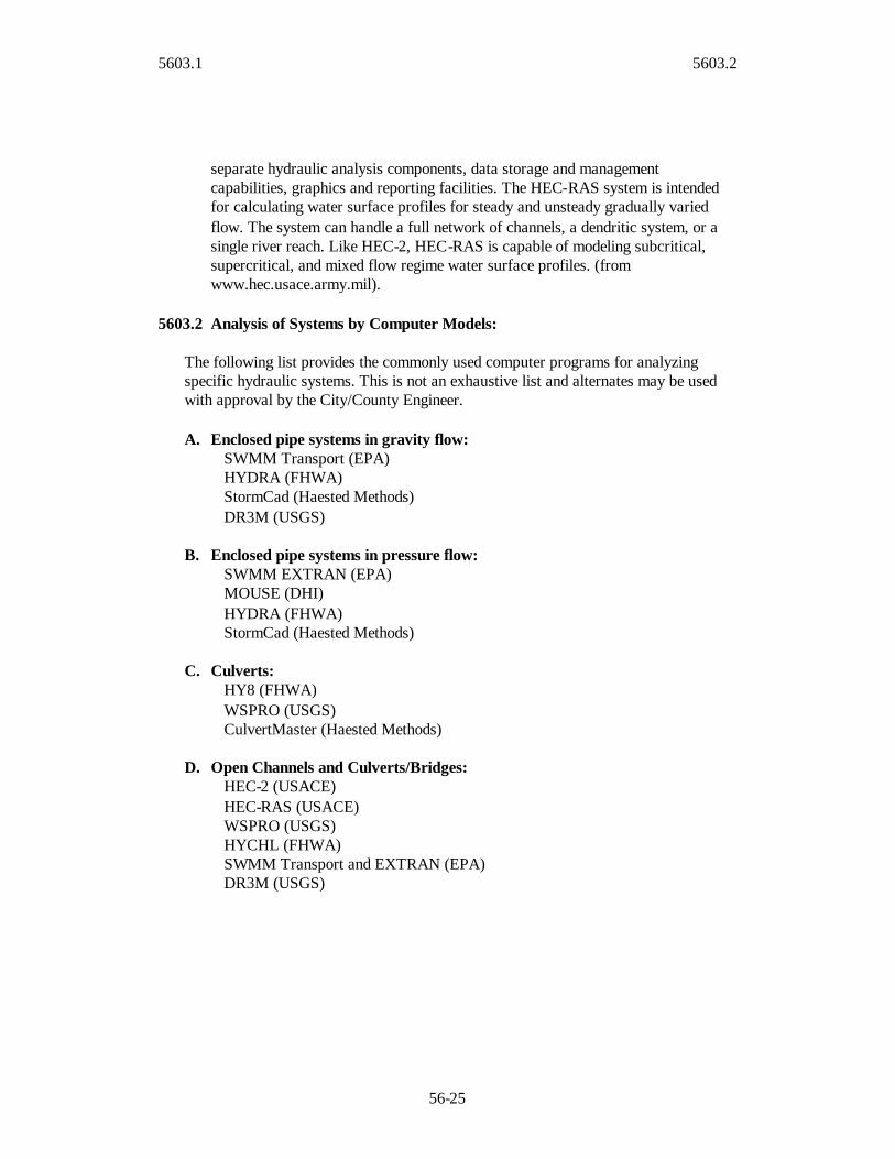
5603.2 Analysis of Systems by Computer Models:
The following list provides the commonly used computer programs for analyzingspecific hydraulic systems. This is not an exhaustive list and alternates may be usedwith approval by the City/County Engineer.
A. Enclosed pipe systems in gravity flow:SWMM Transport (EPA)HYDRA (FHWA)StormCad (Haested Methods)DR3M (USGS)
B. Enclosed pipe systems in pressure flow:SWMM EXTRAN (EPA)MOUSE (DHI)HYDRA (FHWA)StormCad (Haested Methods)
C. Culverts:HY8 (FHWA)WSPRO (USGS)CulvertMaster (Haested Methods)
D. Open Channels and Culverts/Bridges:HEC-2 (USACE)HEC-RAS (USACE)WSPRO (USGS)HYCHL (FHWA)SWMM Transport and EXTRAN (EPA)DR3M (USGS)

5604 5604.2
56-26
SECTION 5604 INLETS, MANHOLES, AND JUNCTION BOXES
5604.1 Inlet Design:
A. Type: Only curb opening inlets shall be used on public streets, except as approvedby the City/County Engineer.
B. Configuration: These minimum dimensions (illustrated by Figure 5604-1) applyto either the lazy-back or steep-face type curbs:
Opening length, inside 4.0 ft (min)Width, perpendicular to curb line, inside 3.0 ft (min)Setback curb line to face 1.0 ft (min)Opening, clear height 6.0 in. (min)Gutter depression at inlet 6 ¼ in. (min)Gutter transition length(a) Both sides in sump and upstream side on slopes 5.0 ft (min)(b) Downstream on slopes 3.0 ft (min)
C. Design Method: Inlets should be designed using Figures 5604-2 through5604-19. Note that the Theoretical Captured Discharge (right side of chart)is the design capacity, 80 percent clogging factor should not be used forinlets on grade, unless deemed necessary by the engineer. Figures 5604-2through 5604-19 describe inlet efficiency as a function of street slope (SeeFigure 5604-3 for design example) and in most cases will require thedesigner to add bypassed flow to the next downstream inlet. Figure 5604-21 describes inlet capacity for sump regions using HEC-22 equation 4-31a.Inlet capacity for sump regions shall be rated at 80 percent of thetheoretical capacity to allow for partial obstruction and clogging. “TypeCG-2 Curb” and Type CG-1 Curb”, as indicated on these figures, refers tothe lazy-back and steep-face style curbs, respectively.
5604.2 Gutter Flow:
Inlets shall be located to limit the width of flow in street gutters at the time of peakdischarge for the design storm specified in 5601.8 B to the following limits:
BACK TO BACK OF CURBSTREET WIDTH IN FEET
MAXIMUM ALLOWABLESPREAD IN EACH OUTSIDE
CURB LANE FROMBACK OF CURB IN FEET*
28 or Less 12.0Over 28 to 36 12.0Over 36 12.0
5604.2 5604.4
56-27
Divided Roadways As Above for Each DirectionRoadway
* spread may exceed these limits within 50 feet of a sump inlet.
In addition to the inlet spacing requirements for limiting width of flow, inlets shall belocate to limit gutter flow from crossing the street centerline at the time of peak dischargefor the design storm to the following limits:
CONDITION CAUSING FLOWCROSSING STREET CENTERLINE
MAXIMUM DISCHARGE,(CFS)
Sump at intersection return* 1.0Transitions to superelevation 1.0Sump at midblock Not AllowedOverflow of non-gutter flow Per 5601.8.B
* For new development, inlets at intersections shall be positioned outside the curb return.
5604.3 Gutter Capacity:
Izzard's Formula shall be used to determine gutter capacity (see Figure 5604-39 forgraphical solution):
nDSzQ
3/82/156.0 where:
Q = The gutter capacity in cubic feet per second
z = The reciprocal of the average cross-slope, including gutter section, infeet per foot
S = The longitudinal street grade in feet per foot
D = The depth of flow at curb face in feet
n = Manning's "n", see Table 5603-1
5604.4 Freeboard Requirements:

5604.5 5604.7
56-28
Any opening which surface water is intended to enter (or may backflow from) thesystem shall be 0.5 feet or more above the hydraulic grade line in the inlet during thedesign storm, specified in Section 5601.8, where such calculation must include minorlosses.
5604.5 Inverts and Pipes:
The crown(s) of pipe(s) entering a drainage structure shall be at or above the crown ofthe pipe exiting from the structure and provide a minimum fall of the invert in thestructure of 0.2 feet for straight flow through the structure or 0.5 feet fall for all othertypes of flow (bends more than 22.5 deflection angle, multiple lines entering,enlargement transition, etc.) through the structure. The desirable minimum fall acrossthe invert is 0.5 feet. Alternatively, the crowns of the pipes may be at or above theEGL of normal flow at design frequency.
The maximum spacing between manholes shall be 500 feet.
5604.6 Street Grade on Vertical Curves:
The following formula shall be used to determine the street grade (Sx) at any point ona vertical curve using plus for grades ascending forward and minus for gradesdescending forward, in feet per foot.
LSSx
SS x
)( 121
where:
Sx = The street grade on a vertical curve at point x, in feet per foot
S1 = The street grade at the PC of a vertical curve, in feet per foot
S2 = The street grade at the PT of a vertical curve, in feet per foot
x = The distance measured from the PC to point x on a vertical curve, in feet
L = The total length of a vertical curve, in feet
5604.7 Loading Conditions for Structures:
Shall be in accordance with Section 5710.3.

5605 5605.3
56-29
SECTION 5605 NATURAL STREAMS
5605.1 Scope:
This section sets forth requirements for the protection of natural streams as aconveyance for stormwater. Unless otherwise provided for by City, State, or Federalordinance, regulation, or standards, existing natural streams shall be preserved andprotected in accordance with this section. Where natural streams are not preserved, thedrainage will be handled through systems designed in accordance with Sections 5606or 5607.
5605.2 Natural Stream Benefits and Characteristics:
Natural streams provide numerous water quality, ecological, and quality of lifebenefits. Protection and preservation of natural streams is a national environmentalobjective, as set forth in the Clean Water Act. Streams and their associated wetlandsprovide critical habitat for plants and wildlife, water quality treatment, and improvedinfiltration of rainfall which lessens flood impacts, recharges groundwater, andpreserves baseflow. Streams provide recreational and open space in communities,improve aesthetics, provide natural landscapes, and enhance adjacent property values.Stable streams in nature maintain a shape in plan, profile, and section that mostefficiently transports the water and sediment supplied to them. The geometry andprocesses of natural streams involve unique terminology and concepts not common toengineered channels or pipe systems. Common features of stream geometry andcharacteristics are presented in Figure 5605–1. Certain definitions are contained inSection 5601. More complete information regarding the character and function ofnatural streams is given in Interagency (2001).
5605.3 Stream Preservation and Buffers Zones:
A. Recommended Approach: It is recommended that Cities adopt comprehensivestream preservation and buffer zone requirements as part of their master plan andenforce those policies during the planning phase of land development.Requirements may be selected to protect environmental and quality of life benefitsand be tailored to local geography and natural resources. The size of buffers maybe adjusted to reflect local experience with stream migration and stability,protection of adjacent wetlands or critical habitat, or water quality treatment.Guidance on stream protection is given in Wegner (1999), National Academy ofSciences (1999), and Heraty (1995). Natural streams should be preserved assystems and not segmented on a project-by-project basis, as the frequentintermixing of natural and man-made systems tends to degrade the function ofboth.
B. Default Approach: Where such comprehensive strategies have not been adopted,the following requirements shall be satisfied for all development/redevelopmentproposed adjacent to or ultimately discharging to an existing natural channel:

5605.3 5605.4
56-30
1. Streams having a tributary area in excess of 40 acres shall be preserved.Preservation of smaller streams is encouraged. Preservation may be waived bythe City/County Engineer where it is impractical, provided that the project hasalso received appropriate state and federal permits.
2. Buffer zones shall be established around all preserved streams. The limit ofbuffer zones shall be formally designated on a plat, deed, easement, orrestrictive covenant, as directed by the City. Buffer widths as measured fromthe ordinary high water mark (OHM) outward in each direction shall exceedthe following:
Contributing drainage Buffer width, from OHM outwards,basin size (acres) measured separately in each directionLess than 40 acres 40 feet40 acres to 160 acres 60 feet160 acres to 5000 acres 100 feetGreater than 5000 acres 120 feet
3. The City/County Engineer may require wider buffers for less stable stream orspecial conditions to address water quality and ecological needs. These widthsprovide only moderate allowance for widening or migration in local streams ofaverage stability. Geotechnical studies may be required if there is a risk ofslope failure due to underlying soil or rock materials, and the buffer widthshall be expanded to contain the zone of failure. Smaller buffers in isolatedlocations may be allowed where provision of the full width is impractical andbank stability concerns have been addressed.
4. No construction or disturbance of any type, including clearing, grubbing,stripping, fill, excavation, linear grading, paving, or building is allowed in thebuffer zone except by permission of the City/County Engineer. Dense standsof native vegetation shall be maintained, particularly in the 25 feet closest tothe top of bank.
5. Unless otherwise accepted by the City/County, any maintenance of riparianbuffers shall be the responsibility of the property owner.
6. For work on existing facilities already located closer to the stream thanallowed above, the new construction shall not encroach closer to the stream.Bank stability concerns shall be addressed. Formal designation of a bufferzone is not required.
5605.4 In Stream Construction - General Requirements:
Construction in streams or their buffer zones shall conform to the general requirementsof this subsection and to the appropriate specific requirements of the subsectionsfollowing:

5605.4 5605.5
56-31
A. Stream Assessment: A stream assessment shall be conducted in accordance withSection 5605.5 for all construction within the buffer zone except for dischargeoutfalls, unless otherwise directed by the City/County Engineer.
B. Energy Management: The pre-project and post-project hydraulic and energygrade lines for the 100%, 10%, and 1% storm flows shall be plotted. The region ofa stream where in-stream construction causes a change in these grade lines isconsidered the zone of influence. The extent of the zone of influence downstreamshall be generally limited by energy dissipation and grade control. The upstreamlimit of the zone may extend a distance beyond the construction as a drawdown orbackwater curve. Within the zone of influence, the energy of the flow on thechannel will be evaluated for the potential of excessive scour, deposition, initiationof headcuts, or other instability. Use of vegetation to increase bank resistance andminimize increases or abrupt changes in velocities is recommended. Bank or bedstabilization may be required in areas of unavoidable velocity or depth increase.
C. Sediment Transport Continuity: The minimum post-project applied shear to thebed of the channel in the zone of influence at the 100%, 10%, and 4% ultimate-conditions storm flow shall not be less than 90% of the minimum pre-projectapplied shear in the zone, so as to maintain the ability of the channel to transportsediment. If such shear stresses cannot be maintained, the engineer will evaluatethe potential for future sediment removal or maintenance.
D. Transitions: In-stream structures shall be designed to gradually blend into thenatural channel and provide a smooth transition of both geometry and roughness.
E. Repair of Disturbed Banks: The side slopes of banks where construction occursshall be restored with vegetation in accordance with Section 5605-13 as quickly aspossible.
F. Professional Judgment: Natural streams are complex, variable, and stronglygoverned by local geology and climate. These standards are based on generalguidelines of good practice on typical local streams and may not be optimal orsufficient in all cases. Specific requirements may be increased or waived by theCity/County Engineer if conditions warrant and decisions should be guided byprudent engineering judgment.
5605.5 Stream Assessment:
When conducted, a stream assessment will extend a minimum of one wavelength upand downstream of the area to be impacted by construction. It shall include thecomponents listed below, except modified by the City/County Engineer to better fitproject needs. An example submittal is shown in Figure 5605-2.
A. Plan Form Analyses and Inventory: The plan-view of the natural stream usingaerial photographs or planning-level aerial survey shall be plotted to an
5605.5 5605.5
56-32
appropriate scale. Field surveys of the entire reach study area is not required. Thefollowing items shall be shown:
1. Ordinary high water mark.
2. Top of bank.
3. Ground contours (if available).
4. "Bank-full" and floodplain for the 1% ultimate-conditions storm (seeparagraph B).
5. Thalweg, locations of riffles and pools, and spacing between riffles (seeparagraph C).
6. Exposed bedrock, areas of differing bed and bank soil or rock materials, andthe D50 and shear stress ratio at each riffle (see paragraph D)
7. Active scour and depositional areas, point bars, and islands.
8. Vegetation within the buffer zone, called out as mowed grass, mowed withtrees, unmowed grass and plants, wooded, and bare. Trees greater than 6"diameter within 25 feet of the top of bank shall be located individually or bygroup. The species of dominant trees should be noted.
9. Meander length, wavelength, meander amplitude, bank-full width, and radiusof curvature for each bend.
10. Total meander and valley length and sinuosity for the reach.
11. Photographs of main channel, streamside vegetation, and each riffle,appropriately referenced to plan-view location.
B. Bank-full Width, Depth and Discharge: If directed by the City/CountyEngineer, the geomorphic "bank-full" width, depth, and discharge shall beestimated using field indicators as detailed in Chapter 7 of USDA (1994). If fieldindicators are not used, "bank-full" flow shall be estimated as the rural-conditions50% storm flow, and the bank-full width and depth estimated based on thedimensions of that flow through the existing channel. This assumption is intendedto provide a rough upper estimate of the bank-full flow.
C. Longitudinal Profile and Sections: The elevations of the profile along thethalweg shall be field surveyed to the nearest 0.1 ft. and the following featuresnoted: riffles, pools, exposed bed rock, and advancing headcuts (areas of bedelevation change that appear to be actively migrating upstream). The top of leftand right bank and any field indicators of bank-full flow such as limits of woodyvegetation or top of point bars shall be plotted at correct elevation along the

5605.5 5605.5
56-33
profile. The bank-full flow and 1% ultimate storm flow profiles shall be plotted.One field cross section shall be surveyed through each pool and riffle, and thedepth and width of bank-full flow and floodplain for the 1% ultimate conditionsstorm shall be shown on each section.
D. Bed and Bank Materials Analyses: The type of rock exposed in the bed andbanks shall be identified. Bank soils shall be reported by Uniform SoilClassification using the visual-manual procedures (ASTM D 2488-00). Themedian (D50) particle size shall be determined using the Wolman Pebble CountMethod (USDA, 1994, Chapter 11). A shear stress ratio shall be calculated foreach riffle based on the applied shear at bank-full flow divided by the critical shearof the D50 particle in the riffle, using methods and tables described below.
E. Critical Shear Stress Analysis: The Shear stress ratio must be less than one atthe extreme downstream point of any development in accordance with theguidelines below:
1. The average applied shear stress (τo ) may be calculated from the hydraulicdata as follows:
τo = γ RS
where γ is the specific weight of water (62.4 pcf), R is the hydraulic radius a t bank-full flow, and S is the water surface slope along the main channel bank-full flow, averaged over several bends in the area of the intervention. Effectiveflow may be calculated using methods described in detail in USACE 2001 ormay be assumed to be equivalent to the 50% storm.
2. The critical shear stress,τc, is that at which particles in the bed or bank areentrained and scour ensues. Shield’s method is used for calculating thecalculating the critical shear stress of spherical, non-cohesive particles, asfollows:
τc = Θ(γs -γ) D50
where γs is the specific weight of sediment, γ is specific weight of water (62.4 lb/ft 3), D50 is the median particle size in the surface layer of bed or banks, andΘis the Shield’s parameter (0.06 for gravel to cobble, 0.044 for sand)
There are limited methods for calculatingc for fine-grained material. Field orlaboratory testing generally determines the critical shear stress for thesematerials. The most widely available source is Chow (1988). Table 7-3, p.165 is particularly relevant. More recently, the USDA Agricultural ResearchService National Sedimentation Laboratory has developed computer softwarefor calculating toe scour (ARS Bank-Toe Erosion Model, Prototype, August2001). As part of that software, there are look-up tables.

5605.5 5605.6
56-34
The combination of these two sources is presented in Table 1. Critical shearstress may also be determined from Urban Water Resources Research Council(1992), Figure 9.6, p. 335.
In lieu of calculated values, the c from Table 5605-1 may be used. Table 1presents critical shear for sediment-laden water and where noted, clear water.The user must exercise judgment as to future conditions. Clear water valuesmay be used below a heavily piped area, concrete channels designed to containthe future flows or immediately below a managed detention pond.
3. The ratio of average boundary stress to critical stress is the shear stress ratio:
shear stress ratio = τo /τc
If bed and bank materials are distinct, then the shear stress ratio should becalculated for each. If the shear stress ratio of either stream bed or bank isgreater than one, the channel is prone to near-term adjustment and anyinterventions should be designed to prevent accelerated erosion. If the bedconsists of rock, then the shear stress ratio is not applicable, unless the rock isprone to fracturing, slaking, or break-up, in which case the median size ofparticle should be used for calculation of the ratio.
F. Plan-Form Ratios: The following ratios shall be calculated, and those that lieoutside the typical range shall be noted. Streams are highly variable and ratiosoutsides these ranges do not necessarily indicate problems:
Ratio Typical RangeMeander length / Wavelength (sinuosity) 1.1 to 1.5Meander length / Bank-full width 10 to 14Radius of curvature / Bank-full width 2 to 5Riffle Spacing / Bank-full width 5 to 7
G. Channel Condition Scoring Matrix: Using information summarized above, thechannel condition scoring matrix given in Table 5605-2 shall be completed. Arating of 12 indicates a stream of moderate stability that will likely require onlystandard levels of protection during construction. A rating between 12 and 18indicates that special measures may be necessary address those issues rated aspoor in the assessment. Streams with a rating greater than 18 may exhibitsignificant system-wide instability and should be studied in more detail by expertsin river engineering and fluvial geomorphology. (This scoring system is newlydeveloped and its results shall be considered provisional.)
5605.6 Discharge Outfalls:
Discharge points for inflows from enclosed systems or constructed channels shall bedesigned as one of the following. Energy management and sediment continuity checks

5605.6 5605.6
56-35
are not required; however, energy dissipation shall be provided to reduce post-development shear stress to pre-development shear stress at the outfall:
A. Primary outfalls are those where the entire upstream channel is replaced by anenclosed system or constructed channel which discharges flow in line with thedirection of the downstream segment. Energy dissipation should be provided at theoutlet to reduce velocities per Section 5606.4. Grade control downstream of theoutlet and energy dissipater should be provided to prevent undermining of theoutfall by future headcuts per Section 5605.10. The alignment and location of theoutfall and associated energy dissipater and grade control should make a smoothtransition into the downstream channel. Primary outfalls shall be used wheneverthe contributing drainage area of the outfalls is greater than 80% of thedownstream channel.
B. Tributary outfalls are primary outfalls located on a tributary to a largerdownstream segment. Energy dissipation and transition to natural stream flowshould take place in the tributary at least one channel width upstream of theconfluence per Section 5606.4. Grade control in the tributary upstream of theconfluence shall be provided if the tributary flow line is higher than the adjoiningchannel or if future incision of the adjoining channel is anticipated. Tributaryoutfalls may be used in all situations of tributary flow.
C. Lateral outfalls are small outfalls that discharge from the banks of a naturalstream. Outfalls shall be located to enter on a riffle or from the outside of a bend,but should generally not enter from the inside of a bend. Outfall pipes shall beoriented perpendicular to the flow of the stream with the invert at or slightly belowtop of the next downstream riffle. Outfalls shall be flush with or setback from thebank. The bank shall be shaped to provide a smooth transition and protected withreinforced vegetation (preferred) or rip-rap. If the outfall is in a bend, it shall beset back from the existing bank a sufficient distance to account for future meandermigration, and the transition shall be graded and reinforced with vegetation. Rip-rap or hard armor protection should not be used in a bend. Perpendicular outfallsmay only be used when the contributing drainage area of the outfall is less than40% of that in the downstream channel.
D. Edge-of-buffer outfalls are discharge points in the outer half of the riparian bufferthat return the discharge to diffused overland flow. Outfalls shall be designed tospread flow and allow overland flow and infiltration to occur. Overland flow shallbe directed to run in the outer portion of the buffer parallel to the channel directionto increase length of flow and prevent short-circuiting directly into the stream.Low weirs and berms may be graded to direct flow and encourage short-termponding. The buffer zone utilized for infiltration shall be maintained in dense,erosion-resistant grasses or grasses reinforced with turf-reinforcing mats designedto withstand the shear stresses of a 10% storm. Edge-of-buffer outfalls that arepart of a system of upland drainage using multiple small, distributed overlandswales and ditches instead of pipes may provide significant infiltration and water
5605.6 5605.8
56-36
quality treatment. Edge-of-buffer outfalls shall only be used if each individualoutfall can be designed to operate without scour or the formation of gullies.
5605.7 Culverts, Bridges, and Above Grade Crossings:
A. Crossings should generally be located on a riffle. If the width of the crossing islarge relative to the length of the riffle, then grade control structures shall beprovided at the riffles upstream and downstream to isolate the impact of thecrossings. If a crossing cannot be made at a riffle, avoid armoring a pool and placeat-grade grade control structures at the riffle immediately upstream anddownstream of the crossing. Maintain sediment transport continuity and avoidaltering the channel cross-section.
B. Realignment of channels to accommodate crossings and their approach should beavoided and minimized as much as possible. Any areas relocated shall have thebanks stabilized in accordance with 5605.13 and shall be included in the reachisolated by upstream and downstream grade control.
C. For bridges the multi-stage channel shape should be maintained and additionalarea to convey the design flow shall be above the elevation of the bank-fulldischarge.
D. For multi-cell pipe and culvert crossings that have a cumulative width larger thanthe bank-full width, those cells wider than the bank-full width shall have a flowlinelocated at the lowest estimated bank-full depth, or a weir wall or other structureupstream of the culvert opening shall be installed with a height to prevent accessto the cell during flows less than bank-full flow. The weir wall shall be designed sothat the hydraulic efficiency at the 1% ultimate conditions storm is not reduced.Without these features, the culvert may have a tendency to build up deposits andlose capacity or require frequent maintenance, particularly when crossings arelocated in sharp bends or streams with high sediment loads.
E. Culverts shall be designed so that there is minimal backwater effect at all flows upto the 4% storm discharge. Energy management and sediment transport continuityshall be checked.
5605.8 Below Grade Stream Crossings:
A. Below grade stream crossings primarily include utility pipelines. Crossings shouldgenerally be at riffles and grade control structures constructed at the riffle, inaddition to or constructed integrally with any encasement of the line the utility mayrequire.
B. If riffle crossing is not feasible, the crossing should be in a pool that is protectedby a downstream grade control structure. The top of crossing elevation should beat least two feet below the top of grade control. Crossings under pools should notbe armored directly, but are protected by downstream grade control.

5605.8 5605.10
56-37
C. Below grade crossings shall be perpendicular to the stream whenever possible. If aperpendicular crossing is not feasible, the grade control protecting the crossingshall be perpendicular.
D. Constriction or alteration of the pre-existing channel shape shall be avoided. Ifalteration occurs, sediment transport continuity and energy management shall beverified. Stream banks shall be repaired using vegetative methods wheneverpossible and the hydraulic roughness of the repaired stream bank should matchthat of the undisturbed stream banks.
5605.9 Grade Control:
A. Where grade control structures are required, they shall be placed in locationswhere the stream bed profile will support the creation or continuance of a riffle.The flowline of the grade control shall match the existing riffle.
B. Where stream slope is less than 2%, the Newberry-style grade control structuredetailed in Figure 5605-3 is recommended. Structures shall be constructed fromdurable stone sized using USACE methodology for steep channels (USACE EM1110-2-1601, page 3-8, Equation 3-5). Rock shall generally comply with USACEgradations as given in (USACE EM 1110-2-1601, Hydraulic Design of FloodControl Channels, Chapter 3). Shotrock with sufficient fines to fill voids may beused. The use of filter fabric and uniform gradations of stone are discouraged instream beds.
C. Where grades are in excess of 2%, low-drop step structures should be used.
D. Alternate styles of grade control may be approved by the City/County Engineer.Guidance for grade control design is given in Thomas et.al.
E. Construction of new grade controls structures may be waived by the City/CountyEngineer if it is determined that existing riffles are adequate to prevent or retardadvancing headcuts, or if it is preferable to accept the risk of future headcut thanto further disturb the channel.
F. When grade control is not part of a larger project, energy management andsediment continuity checks are not required.
5605.10 Floodplain Fills:
No fill shall be placed within the bank-full floodplain, nor should fill be placed withinthe designated buffer zone. Fill placed outside these limits shall not cause an rise in thefloodplain of the 1% ultimate conditions storm beyond the limits of the propertycontrolled by the developer, unless authorized by the City/County Engineer. Fillsplaced within floodplain designated as a special flood hazard area by FEMA shall

5605.11 5605.12
56-38
conform to FEMA and community floodplain management requirements. Energymanagement and sediment transport continuity shall be checked.
5605.11 Flood Control Projects:
A. The flood control projects that increase conveyance capacity in natural streamsshould generally be limited to cases where existing buildings or infrastructure facesignificant damage or life and safety issues. Projects to lower floodplain elevationsto facilitate new development near streams at lowered elevations should beavoided.
B. The portion of the channel within the bank-full floodplain should be leftundisturbed if possible, with conveyance increases primarily from excavation of alarger cross sectional area in the over-bank. Excavated areas within the bufferzone should be revegetated with dense, native-type vegetation. Reducing roughnessin the over-bank by paving or mowing to increase velocities should be avoided.
C. If adequate conveyance cannot be provided using the methods above, thenexcavation of the over-bank below the bank-full floodplain and/or reduction inover-bank roughness may be necessary. Energy management and sedimentcontinuity should be checked. Effort should be made to avoid direct widening ofthe active channel at low flows and to minimize disturbance of the active channeland nearest adjacent stream-side vegetation.
5605.12 Bank Stabilization Projects:
A. Bank stabilization projects should generally be limited to cases where existingbuildings or infrastructure face significant property damage or safety issues.Projects to stabilize banks to facilitate reductions in buffer widths for newconstruction should be avoided.
B. Prior to stabilization, the causes of the instability should be considered, includingthe stream’s current phase of channel evolution (Interagency, 2001, Chapter 7)and direction of meander migration. Stabilization may be unnecessary if a channelhas ceased incision and widening and is in the process of deposition andrestoration. If stability issues appear widespread or complex, a systematicevaluation of the stream system by professionals with expertise in riverengineering and fluvial geomorphology may be justified.
C. Instability caused by geotechnical failure (slumping of banks due to weak soils inthe adjacent slopes) shall be distinguished from fluvial failure (erosion of bankscaused by stream flows). For geotechnical issues, a geotechnical engineer shallevaluate the slope stability. Geotechnical designs shall provide for a 1.5 factor ofsafety (ratio of theoretical resisting forces to driving forces) against slope failurewhere it would endanger buildings, roadways, or other infrastructure, unless alower factor of safety is approved by the City/County Engineer.
5605.12 5605.12
56-39
D. Bank stability projects should have a design life greater than the useful life of thefacility being protected, or a life cycle cost analyses shall be performed thatconsiders replacement and repair over the entire protection period. Responsibleparties for future maintenance should be identified.
E. Stabilization should begin and end at stable locations along the bank. Bankstabilization should be limited to areas of potential erosion and are rarely requiredon the inside of bends. For long projects, stabilization may alternate from side toside and is rarely necessary across an entire cross section. The existing crosssection should be mimicked to the extent practical and need not be planar oruniform over the entire length. Grade control shall be provided at the riffle bothupstream and downstream of the stabilization to isolate it from the surroundingstream and protect the foundation from undercutting. Control at intermediatepoints for longer projects may also be required. Energy management and sedimenttransport continuity shall be checked, and energy dissipation provided if necessary.
F. "Hard-Armor" projects are those projects that use rip-rap, placed stone, gabions,retaining walls, or other rigid structures to provide geotechnical and fluvialstability. Such projects shall be designed in accordance with EM 1110-2-1205(USACE, 1989), EM1110-2-1601 (USACE, 1994), or HEC-11 (FHWA 1989).Materials shall be sized to prevent dislodgement in the 1% storm. Gradationshould comply with USACE or FHWA recommendations. Stones should be placedto maintain roughness and variations. All material shall be well placed to ensureinterlock and stability. Materials shall be keyed into the bed and banks withadequate allowance for scour along the toe and the structure should have adequatefoundation. Vertical walls should be avoided when possible as they tend toconcentrate scour at their toe and are typically smoother than the natural channel.
G. Soil bioengineering involves the use of living vegetation in combination with soilreinforcing agents such as geogrids to provide bank stabilization by increasing soilshear resistance, dewatering saturated soils, and by reducing local shear stressesthrough increased hydraulic roughness.
1. Bio-engineering projects shall be designed in accordance with the principals ofNRCS (1996) and Gray and Sotir (1996). Designs will be tailored to theurban environment by consideration of the requirement for immediatefunctionality upon construction, the extreme variability and high shear stressof urban flows and the availability of mechanized equipment and skilledoperators.
2. Selection of plants and specifications for planting methods and soilamendments shall be prepared by a professional competent in the biologicaland stabilization properties of plants.
3. Plants selected shall be appropriate to local conditions and shall be nativevarieties to the greatest extent practical. Evaluation of local conditions
5605.12 5605.12
56-40
includes assessment of site microclimate, bank slope, soil composition,strength and fertility, type and condition of existing vegetation, proximity toexisting infrastructure, soil moisture conditions and likelihood of wildlifepredation. Engineering factors influencing plant selection include frequency,height and duration of inundation, near-bank shear stress, size and volume ofbed load as well as depth and frequency of scour.
4. Plants may be either locally harvested or purchased from commercialnurseries. When harvesting, no more than 10% of a given stand may beremoved and no plant on the state rare or endangered species list may beharvested or damaged in harvesting operations. Plant material grown near themetropolitan area is adapted to local climatic conditions and is preferred overmore remote sources. Some species such as red maple are particularlysensitive to locale and may only be used if locally available. Seed, plant plugs,rhizomes, whips, live stakes, bare root and container stock may be used. Turfgrasses, noxious or invasive species shall not be used. A variety of plantspecies shall be used to provide greater reliability to a design. For criticalfunctions such as protection from toe scour a minimum of three species shouldgenerally be employed.
5. Soil bioengineering methods are properly applied in the context of a relativelystable stream system, and relevant general requirements for all stream bankstabilization projects given in this section apply to bio-engineered projects.Soil bioengineering alone is not appropriate when the zone of weakness liesbelow the root zone of the plantings, or when rapid draw down can occur,such as in a spillway or dam embankment.
H. Composite methods are those which employ both hard armor and soil bio-engineering. Typically, armor for toe protection in critical locations is provided,with soil-bioengineering for the remainder. Design principals for both hard armorand soil-bioengineering shall be observed as appropriate.
I. In-stream Stability Structures: In-stream structures are used to focus flow,control grade, dissipate energy and selectively lower near-bank stress. Streambarbs, weirs, guide vanes, vegetative sills, longitudinal peak stone, and gradecontrols are among the more commonly used in-stream structures. Whenconstructed of natural material such as rock, such structures also create aquatichabitat. They may be used alone or in combination with hard armor, bio-engineering or composite methods. In-stream structure design is a riverengineering practice and is beyond the scope of this standard. Preliminaryguidance and references for the design of some common structures is given inCastro (1999) and Interagency (2001), Chapter 8 and Appendix A.
5605.13 5605.14
56-41
5605.13 Stream Restoration:
Restoration of urban streams is defined as the re-establishment of natural channelgeometry, materials and vegetative buffers with the intent of restoring naturalgeometry and functions to streams that have been disturbed or eliminated. While thereare significant potential ecological and quality of life benefits from stream restoration,successful design is data-intensive and requires an interdisciplinary approach. Designof stream restoration projects is beyond the scope of this standard. Interagency (2001)describes the general procedures, benefits, and requirements of stream restoration.
5605.14 Comprehensive Stream Management:
The standards set forth in preceding sections provide a moderate degree of mitigationfor potential damages from individual construction projects in streams of averagestability. For more sensitive streams or to obtain a greater degree of protection, Citiesor Counties may elect to implement comprehensive strategies for stream management.Such strategies should be based on specific investigations of the particular streams andwatersheds in the City and consider local geology, geography, climate, and ecology.Strategies may include optimized or County stream buffers (see section 5605.3),hydrology controls, and comprehensive grade control. Detailed requirements for suchstudies and strategies is beyond the scope of this standard, and should be developed inconsultation with professionals competent in river engineering and fluvialgeomorphology. The following general recommendations may be considered:
A. Hydrology Controls for Channel Protection: Channels respond to changes inflow volumes and recurrence by altering width, depth, velocity, suspended load,meander radius, wavelength and pool and riffle. Avoiding significant changes inflow volume and recurrence should reduce the likelihood of major changes instream form. Volume control may include practices that encourage infiltration,evapotranspiration, and short-term detention or retention. A successful strategywould require limitations on volume, duration and magnitude of post developmentdischarges at a number of discharge points, including common storms such as the100% storm. The tail of hydrographs would probably need to mimic groundwaterbaseflow. The cumulative effect of multiple detention/retention structures onduration of high flows would be considered. The impact of large impoundments orretention lakes on trapping sediment and interrupting sediment transport would beconsidered. Volume control for channel protection would likely requiresignificantly different control requirements than traditional detention practices thatfocused primarily on flood control from extreme events.
B. Grade Control: In watersheds subject to deep, rapid, and extensive incision ordowncutting, a comprehensive program of controlling bed elevation (gradecontrol) may be the most practical method of preserving stream function andavoiding future bank stability concerns. Streams with easily eroded soils andlacking in shallow bedrock are highly susceptible to extensive degradation.Existing and proposed crossing points such as culverts, bridges, and encased

5605.14 5605.14
56-42
underground utilities should be incorporated into the program. Selection of gradeelevations would be based on historical data, flooding or space constraints,restoration of wetlands and streambank hydrology, channel depths, and otherrelevant data.

5606 5606.4
56-43
SECTION 5606 ENCLOSED PIPE SYSTEMS
5606.1 Easements:
Permanent easements shall be dedicated to the City/County for operation andmaintenance of the storm drainage facilities. Easement width shall not be less than 15feet, or the outside width of the pipe or conveyance structure plus 10 feet; whichever isgreater. Easements shall be centered on the pipe.
A. Permanent: The City/County Engineer may require wider easements when otherutilities are located within the same easement and/or when the depth of cover isgreater than 4 feet.
B. Temporary: Temporary construction easements of sufficient width to provideaccess for construction shall be acquired when the proposed work is located inareas developed prior to construction.
5606.2 Capacity:
Capacity shall be determined in accordance with Section 5603. Minimum design pipesize shall be 15-inch in diameter. For partially full pipe flow, Figure 5606-1 can beused to obtain hydraulic parameters of the flow.
5606.3 Pressure Flow:
After considering the discussion presented in Section 5603.1 A, an enclosed systemmay be designed to operate with pressure flow, for the design storms specified inSection 5601.8, if all the following conditions are met:
A. The Hydraulic Grade Line (HGL) must be 0.5 feet below any openings to theground or street at all locations.
B. Watertight joints capable of withstanding the internal surcharge pressure are usedin the construction.
C. Appropriate energy losses for bends, transitions, manholes, inlets, and outlets, areused in computing the HGL.
D. Energy methods (Bernoulli's equation) must be used for the computations.
5606.4 Energy Dissipation:
The outfall, as defined in Section 5605.6, of all enclosed systems shall include energydissipation sufficient to transition outlet flows to velocities and applied shear stressesconsistent with the normal flow conditions in the receiving channel for the range offlows up to and including the 1% storm. Calculations, at a minimum, should includethe 100%, the 10% and the 1% storms.

5606.4 5606.4
56-44
Energy dissipation for lateral outflows to natural streams and edge of buffer outfalls toriparian buffers shall follow the guidance in Section 5605.6.
Effective energy dissipating structures shall be provided if necessary to meet therequirements stated in Tables 5605-1 and 5606-1. Examples of energy dissipatingstructures are:
Check Dams Level Spreaders Hydraulic Jump Basins Impact Baffle Basins Plunge Pool and Plunge Basin Slotted-Grating or Slotted Bucket Dissipaters Stilling Basins Rock Revetment Internal Pipe Rings
Grade control shall be provided downstream of the dissipator or shall be constructedintegrally with it.
The suitability of each method is site dependent and subject to approval by theCity/County Engineer. Table 5606-3 lists methods and applicability. Energy dissipatersshall be designed according to the criteria and procedures defined in professionallyacceptable references. Several such references include:
A. United States. Department of the Interior. Bureau of Reclamation. Design ofSmall Dams. 1987 ed. Denver: GPO, 1987.
B. United States. Department of the Interior. Bureau of Reclamation. A WaterResource Technical Publication. Engineering Monograph No. 25. HydraulicDesign of Stilling Basins and Energy Dissipaters. 1978 ed. GPO, 1978.
C. Federal Highway Administration (FHA), 1983. Hydraulic Design of EnergyDissipaters for Culverts and Channels, Hydraulic Engineering Circular (HEC) No.14.
D. US Army Corps of Engineers, 1994. Hydraulic Design of Flood Control Channels,US Army Corps of Engineers Engineer Manual EM 1110-2-1601.
E. Bridge Scour and Stream Instability Countermeasures Experience, Selection, andDesign Guidance (Latest Edition), National Highway Institute,HEC No. 23.
F. River Engineering for Highway Encroachments, Highways in the RiverEnvironment, U.S. Department of Transportation, Federal HighwayAdministration, Publication No. FHWA NHI 01-004, December 2001.
5606.5 5606.6
56-45
5606.5 Velocity Within the System:
The velocity within the system shall be between 3 and 20 feet per second.
5606.6 Loading:
A. Cover: Minimum depth of cover shall be 18 inches.
B. Minimum Loading Conditions:
1. Live load: H-20.
2. Unit Weight of soil cover: 120 pcf.
3. Rigid pipes shall be bedded and backfilled to provide a minimum factor ofsafety of 1.5 at the 0.01-inch crack loading condition.

5607 5607.4
56-46
SECTION 5607 ENGINEERED CHANNELS
5607.1 Introduction:
The criteria in this section apply to open channels that are not natural. Naturalchannels are covered in Section 5605. New buffers and filter strips are not requiredbecause engineered channels are strictly for conveyance.
5607.2 Easements:
Permanent easements shall be dedicated to the City/County for operation andmaintenance of open channels that will be publicly maintained.
A. Engineered Channels: Easements shall be as wide as the top of bank width; plus10 feet on each side. Easements shall be continuous between street rights-of-way.When an improved channel begins or ends at a point other than the right-of-way ofa dedicated street, a 15-foot or wider easement graded so as to permit access bytruck shall be dedicated from the end of the channel to a street right-of-way. Theseare minimum requirements.
Generally, easements shall be required for swales that collect stormwater runoff frommore than two acres or as required by the City/County.
B. Roadside Channels: Roadside ditches are engineered channels that are locatedwholly or partly within the street right-of-way. Roadside ditches in the street right-of-way do not require an easement. Otherwise, roadside ditches shall have adedicated easement from the street right-of-way extending to five feet outside ofthe top of the outside bank of the channel.
5607.3 Freeboard:
Freeboard shall not be required above the design headwater pool elevation at culvertentrance.
5607.4 Channel Linings:
A. Minimum lining height shall be the selected design storm water profile plus atleast a 0.5-foot freeboard.
B. All channel linings, except turf, shall contain provision for relieving backpressures and water entrapment at regular intervals.

5607.4 5607.6
56-47
C. Lining height on the outside bend of curves shall be increased by:
4Dy where:
y = Increased vertical height of lining in feetD = Depth of design flow in feet
Increased lining height shall be transitioned from y to zero feet over a minimum of:
1. y30 feet downstream from the point of tangency (P.T.).
2. y10 feet upstream from the point of curvature (P.C.).
5607.5 Lining Material:
The types of lining material listed in Table 5606-1 shall be used to control damage anderosion. All riprap, grouted riprap, and gabion linings shall be designed with a filterfabric in conformance with Section 2605.2.C.2. The design of the lining material shallprotect the channel for conditions up to the 1% storm. This criteria may be reduced tothe 10% storm if the City/County Engineer approves and if responsibility for repair ofchannel linings in storms greater than 10% is clearly established.
Other types of lining materials not specifically listed in Table 5606-1 may be usedwhen approved by the City/County Engineer.
Concrete lined open channel bottoms are prohibited, unless a waiver to this criterion isgranted by the City/County Engineer.
5607.6 Side Slopes:
A. Side slopes shall not be steeper than:
1. 3 horizontal to 1 vertical for turf lining.
2. 2.5 horizontal to 1 vertical for all other lining materials, unless a geotechnicalanalysis indicates a steeper slope can be used.
3. Flatter if necessary to stabilize slopes.
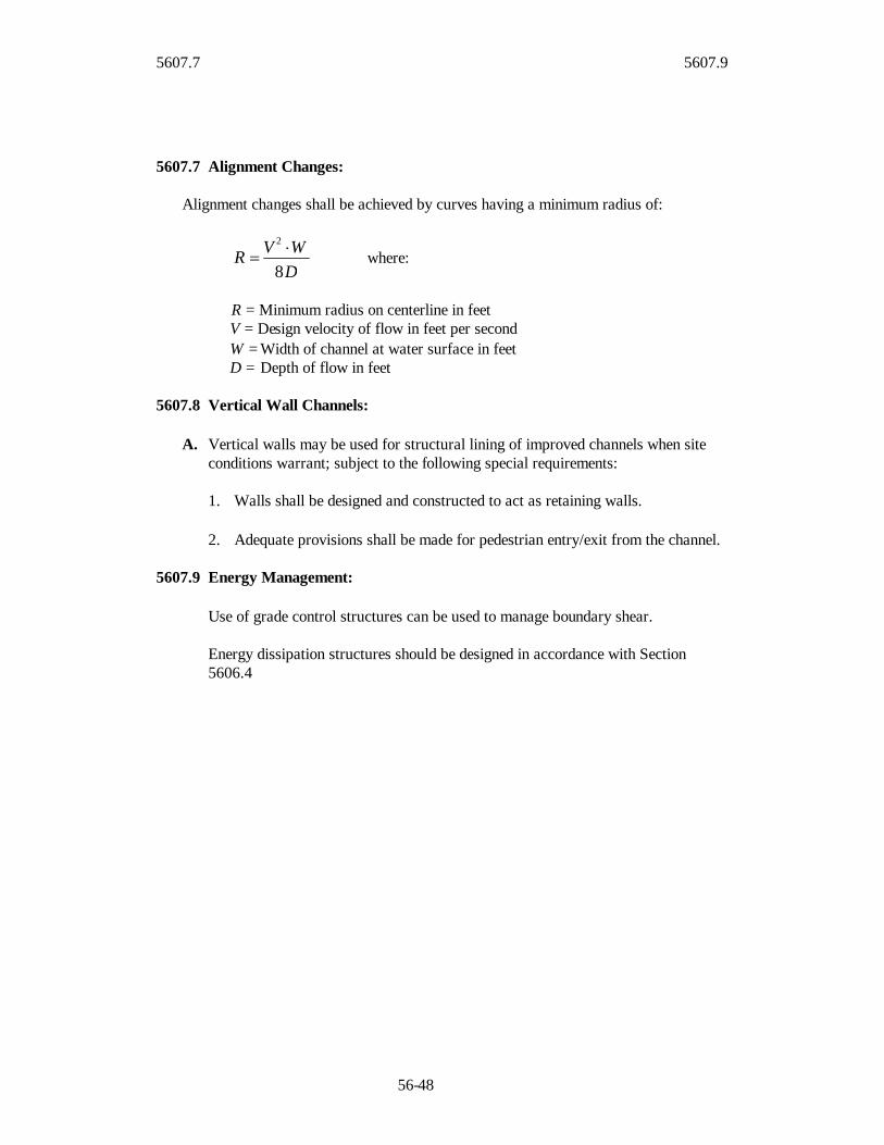
5607.7 5607.9
56-48
5607.7 Alignment Changes:
Alignment changes shall be achieved by curves having a minimum radius of:
DWVR
8
2 where:
R = Minimum radius on centerline in feetV = Design velocity of flow in feet per secondW = Width of channel at water surface in feetD = Depth of flow in feet
5607.8 Vertical Wall Channels:
A. Vertical walls may be used for structural lining of improved channels when siteconditions warrant; subject to the following special requirements:
1. Walls shall be designed and constructed to act as retaining walls.
2. Adequate provisions shall be made for pedestrian entry/exit from the channel.
5607.9 Energy Management:
Use of grade control structures can be used to manage boundary shear.
Energy dissipation structures should be designed in accordance with Section5606.4
5608 5608.3
56-49
SECTION 5608 STORMWATER DETENTION AND RETENTION
5608.1 Scope:
This section governs the requirements and design of stormwater detention and retentionfacilities.
5608.2 Access and Easements
Permanent access and buffers must be provided for maintenance of a detention facilitywith the following minimum requirements:
A. The water surface of the design storage pool shall be a minimum of 20 feet fromproperty lines and building structures. A greater distance may be necessary whenthe detention facility might compromise foundations or slope stability is aconsideration.
B. A 15 foot wide access strip, with slopes less than 5 horizontal to 1 vertical, shallbe provided around the perimeter of the facility, unless it can be demonstrated thatall points of the facility can be maintained with less access provided.
C. The property owner shall also maintain a minimum 15 foot wide access route tothe detention facility from a street or parking lot.
D. Structures, inlet pipes, outlet pipes, spillways, and appurtenances required for theoperation of the facility shall also be provided access which is no less thaneasement widths established in Sections 5606.1 and 5607.2.
Easements are frequently not required for detention facilities, because a detentionfacility is typically maintained by the property owner. If the detention facility is notmaintained by the property owner or involves multiple ownerships, easements must bededicated to the party responsible for maintenance. At a minimum the dedicatedeasements shall include: 1) the detention pond per se, which extends to the designstorage pool elevation and the toe of the embankment slope; 2) appurtenances; and 3)access required by items B through D above.
5608.3 Maintenance and Continued Performance
Maintenance responsibility for all elements of the detention facility should bedesignated prior to construction of any detention facility. However, when nodesignation is made the property owner shall be considered the responsible party.Annual or more frequent inspections shall be made by the responsible party to assurethat all inlet and outlet structures are fully functional and the detention basin has fullstorage capacity.

5608.4 5608.4
56-50
5608.4 Performance Criteria:
A. General Provisions:
1. Detention/retention facilities shall have 1,000 acres or less area tributary tothe facility.
2. Dams which are greater than 10 feet in height but do not fall into State orFederal requirement categories shall be designed in accordance with latestedition of SCS Technical Release No. 60, “Earth Dams and Reservoirs”, asClass “C” structures.
3. All lake and pond development must conform to local, state, and federalregulations. Legal definitions and regulations for dams and reservoirs can befound in the Missouri Code of State Regulations, Division 22, and the State ofKansas Rules and Regulations, KSA 82a-301 through 305a.
B. Computational Methods:
1. Time of Concentration and Travel Time: Refer to Section 5602 for acceptablehydrology methods.
2. Temporary Storage Volume: A preliminary value of the storage requirementmay be obtained through methods outlined in (SCS, 1986, Chapter 6) or otheracceptable methods. The storage shall be checked during routing of designhydrographs through the basin and adjusted appropriately.
3. Hydrograph Routing: The storage indication method (Modified Puls) ofrouting a hydrograph through a detention basin may be utilized. Reference:(Chow, 1964).
C. Release Rate: The maximum release rate from any development for the 1%, 10%and 100% storms shall be limited according to Section 5601.5-A-4 and thedecision flowchart in Figure 5601-1, “Guide to Stormwater Management for SiteDevelopment”.
D. Detention Basin Size: Owners/engineers may utilize methodology outlined in(SCS, 1986). A Type II rainfall distribution shall be the required stormhyetograph. Hydrologic simulation models shall be based on not less thanAntecedent Moisture Condition II (see Section 5602.2). Maximum detentionstorage shall be based upon the allowable release rate and upon the developedcondition for the site. Basin volume shall be sized for the 1%, 24-hour designstorm. Cities and Counties may establish additional standards for other storm sizesin order to provide stream channel and water quality protection.

5608.4 5608.4
56-51
E. Primary Outlet Works: The primary outlet shall be designed to meet thefollowing requirements:
1. The outlet shall be designed to function without requiring attendance oroperation of any kind or requiring use of equipment or tools, or anymechanical devices.
2. All discharge from the detention facility when inflow is equal to or less thanthe 1% inflow shall be via the Primary outlet.
3. The design discharge rate via the outlet shall continuously increase withincreasing head and shall have hydraulic characteristics similar to weirs,orifices or pipes.
4. For dry detention basins, the design shall allow for discharge of at least 80percent of the detention storage volume within 24 hours after the peak orcenter of mass of the inflow has entered the detention basin.
5. Ponds shall be designed with a non-clogging outlet such as a reverse-slopepipe, or a weir outlet with a trash rack. A reverse-slope pipe draws frombelow the permanent pool extending in a reverse angle up to the riser andestablishes the water elevation of the permanent pool. Because these outletsdraw water from below the level of the permanent pool, they are less likely tobe clogged by floating debris.
6. All openings shall be protected by trash racks, grates, stone filters, or otherapproved devices to insure that the outlet works will remain functional. Noorifice shall be less than 3 inches in diameter. (Smaller orifices are moresusceptible to clogging).
F. Emergency Spillways: The emergency spillway may either be combined with theoutlet works or be a separate structure or channel meeting the following criteria:
1. Elevation: Emergency spillways shall be designed so that their crest elevationis 0.5 feet or more above the maximum water surface elevation in thedetention facility attained by the 1% storm.
2. Capacity: In cases where the impoundment/emergency spillway is notregulated by either State or Federal agencies, the emergency spillway shall bedesigned to pass the 1% storm with 1 foot of freeboard from the design stageto the top of dam, assuming zero available storage in the basin and zero flowthrough the primary outlet. This design provides an added level of protectionin the event of a clogged primary outlet or a subsequent 1% storm event thatoccurs before the flood pool from the initial storm event recedes to theprincipal outlet elevation.
5608.4 5608.5
56-52
G. Draw Down Provision: Drain works consisting of valves, gates, pipes, and otherdevices as necessary to completely drain the facility in 72 hours or less whenrequired for maintenance or inspection shall be provided.
H. Erosion Control: Primary outlet works, emergency spillways, and drain works,as well as conveyance system entrances to detention basins, shall be equipped withenergy dissipating devices as necessary to limit shear stresses on receivingchannels. See Tables 5605-1 and 5606-2 for shear stress criteria.
5608.5 Detention Methods:
In addition to the foregoing criteria, the following shall be applicable, depending on thedetention alternative(s) selected:
A. Wet Bottom Basins/Retention Facility: For basins designed with permanentpools:
1. Sediment Forebay: A sediment forebay shall be provided to trap coarseparticles. Refer to the “Mid-America Regional Council and American PublicWorks Association; Manual for Best Management Practices for StormwaterQuality” for typical design specifications and configurations of sedimentforebays.
2. Minimum Depth: The minimum normal depth of water before theintroduction of excess stormwater shall be four feet plus a sedimentationallowance of not less than 5 years accumulation. Sedimentation shall bedetermined in accordance with the procedures shown in Figure 5608-1
3. Depth for Fish: If the pond is to contain fish, at least one-quarter of the areaof the permanent pool must have a minimum depth of 10 feet plussedimentation allowance.
4. Side Slopes: The side slopes shall conform as closely as possible to regradedor natural land contours, and should not exceed three horizontal to onevertical. Slopes exceeding this limit shall require erosion control and safetymeasures and a geotechnical analysis.
B. Dry Bottom Basins/Detention Facility: For basins designed to be normallydry:
1. Interior Drainage: Provisions must be incorporated to facilitate interiordrainage to outlet structures. Grades for drainage facilities shall not be lessthan two percent on turf. Concrete swales, with a minimum gradient of 1.0percent, may be used as needed to conduct stormwater from turfed bottomareas to the outlet structure if the shear stress ratio is greater than 1.
2. Earth Bottoms: Earth bottoms shall be sodded.

5608.5 5608.6
56-53
3. Side Slopes: The side slopes of dry ponds should be relatively flat to reducesafety risks and help to lengthen the effective flow path. Slopes shall not besteeper than three horizontal to one vertical and at least 25% of the perimetershall have a slope of 5 to 1 or flatter.
4. Multipurpose Feature: These shall be designed to serve secondary purposesfor recreation, open space, or other types of use which will not be adverselyaffected by occasional or intermittent flooding, if possible.
C. Rooftop Storage: Detention storage may be met in total or in part by detention onroofs. Details of such designs shall include the depth and volume of storage,details of outlet devices and downdrains, elevations and details of overflowscuppers, and emergency overflow provisions. Connections of roof drains tosanitary sewers are prohibited. Design loadings and special building and structuraldetails shall be subject to approval by the City/County Engineer.
D. Parking Lot Storage: Paved parking lots may be designed to provide temporarydetention storage of stormwater on a portion of their surfaces. Generally, suchdetention areas shall be in the more remote portions of such parking lots. Depthsof storage shall be limited to a maximum depth of seven inches, and such areasshall be located so that access to and from parking areas is not impaired.
E. Other Storage: All or a portion of the detention storage may also be provided inunderground or surface detention areas, including, but not limited to, oversizedstorm sewers, vaults, tanks, swales, etc.
5608.6 Required Submittals:
A. The Owner shall submit the following information and data to the City/CountyEngineer.
1. Elevation-area-volume curves for the storage facility including notation of thestorage volumes allocated to runoff, sediment, and permanent residual waterstorage for other uses (wet basins only).
2. Inflow hydrographs for all (1, 10, and 100-percent) design storms.
3. Stage-discharge rating curves for each emergency spillway, primary outletworks and combined outlets and overflows.
4. Routing curves for all (1, 10 and 100-percent) design storms with time plottedas the abscissa and the following plotted as ordinates:
a. Cumulative inflow volume.
5608.6 5608.7
56-54
b. Cumulative discharge.
c. Stage elevation.
d. Cumulative storage.
5608.7 Additional Requirements:
A. Access: Provisions shall be made to permit access and use of auxiliary equipmentto facilitate emptying, cleaning, maintenance, or for emergency purposes.
B. Underground Storage: Underground detention facilities shall be designed withadequate access for maintenance (cleaning and sediment removal). Such facilitiesshall be provided with positive gravity outlets. Venting shall be sufficient toprevent accumulation of toxic or explosive gases.

5609 5609.5
56-55
SECTION 5609 PLAN REQUIREMENTS
5609.1 Scope: The section governs the preparation of plans for stormwater systemprojects
5609.2 General: The plans shall include all information necessary to build and check thedesign of storm drainage systems and related appurtenances. The plans shall bearranged as required by the City Engineer of local governing agency. Applicablestandard plans of the local governing agency may be included in whole or by reference.Plans shall be sealed by a Registered Professional Engineer in the state of the City orgoverning agency and shall be submitted to the local governing agency for review.
5609.3 Type of Sheets in Plans: The plans shall consist of:
A. Title sheetB. General layout sheetsC. Plan and profile sheetsD. Cross-section sheetsE. Drainage area map and tableF. Standard and special detail sheetsG. Traffic control plans (if required)H. Temporary erosion control plansI. Grading plans (if required)J. Property line and easement sheets (if required)
Each sheet shall contain a sheet number, including the individual sheet number and thetotal number of sheets, proper project identification and all revision dates. TheEngineer’s seal shall appear on the title sheet and other sheets as required by the Statelicensing requirements.
5609.4 Sheet Sizes: The suggested sheet size is 22 inches by 36 inches with 2 inchbinding margin along the left end of the sheets. All sheets in a given set of plans shallbe of the same size. Plan and profile shall be drawn on combined or separate plan andprofile sheets to minimum scales indicated herein.
5609.5 Scales: Plans shall be drawn at the following minimum scales. Other scales maybe needed to clearly present the design. Bar Scales shall be shown on each sheet foreach scale.
Plan: 1 inch = 20 feet
Profile:Vertical: 1 inch = 5 feetHorizontal: 1 inch = 20 feet
5609.5 5609.7
56-56
Cross-sections:Vertical: 1 inch = 5 feetHorizontal: 1 inch = 10 feet
Drainage area map:Onsite: 1 inch = 200 feetOffsite: 1 inch = 1,000 feet
Structural Plans: ¼ inch = 1 foot
5609.6 Required information for Title Sheet:
A. Name of project.B. Project number.C. Index to sheets.D. A location map adequately showing the project location in relation to major
streets, with north arrow and scale. Map shall be oriented with north arrow up.E. A signature block for local governing agency approval.F. Name, address and telephone number of the consulting engineer and
owner/developer as well as signature block for the owner/developer.G. A legend of symbols shall be shown that apply to all sheets.H. List containing name and telephone number of each utility company and state One-
Call system.I. Engineer’s seal, signed and datedJ. Other information as per local governing agency requirements.
5609.7 Required Information for General Layout Sheet:
A. General Notes: Minor construction notes shall appear on the proper plans andprofile sheets.
B. North arrow and bar scale. North arrow shall be oriented up or to the right.C. Surveyed or aerial base map detail indicating existing man-made or natural
topographical features, such as buildings, fences, trees, channels, ponds, streams,etc… and proposed and existing utilities.
D. Subdivision information including, but not limited to Rights-of-Way, Property andlot lines, existing and proposed easements, subdivision nomenclature, Street namesand other pertinent information impacting the project.
E. Identification and location of all existing and proposed drainage features.F. Elevation and location of all applicable benchmarks: NGVD datum or as required
by local governing agency. A minimum of two (2) benchmarks are required foreach project.
G. Survey control line or base line with adequate ties to land lines.H. Locations of test borings if taken.I. Existing and finish grade contours at intervals of 2.0 feet or less in elevation; or
equivalent detail indicating existing and finish grades and slopes.
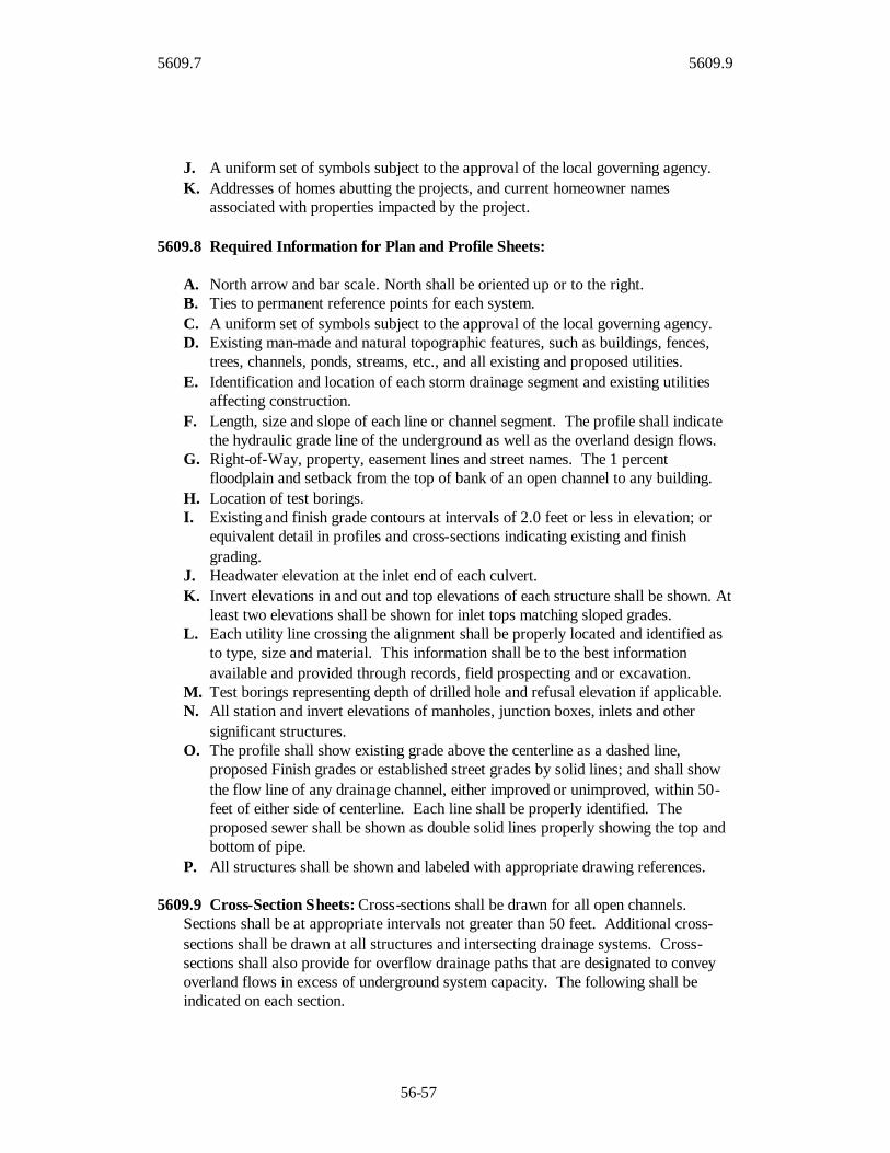
5609.7 5609.9
56-57
J. A uniform set of symbols subject to the approval of the local governing agency.K. Addresses of homes abutting the projects, and current homeowner names
associated with properties impacted by the project.
5609.8 Required Information for Plan and Profile Sheets:
A. North arrow and bar scale. North shall be oriented up or to the right.B. Ties to permanent reference points for each system.C. A uniform set of symbols subject to the approval of the local governing agency.D. Existing man-made and natural topographic features, such as buildings, fences,
trees, channels, ponds, streams, etc., and all existing and proposed utilities.E. Identification and location of each storm drainage segment and existing utilities
affecting construction.F. Length, size and slope of each line or channel segment. The profile shall indicate
the hydraulic grade line of the underground as well as the overland design flows.G. Right-of-Way, property, easement lines and street names. The 1 percent
floodplain and setback from the top of bank of an open channel to any building.H. Location of test borings.I. Existing and finish grade contours at intervals of 2.0 feet or less in elevation; or
equivalent detail in profiles and cross-sections indicating existing and finishgrading.
J. Headwater elevation at the inlet end of each culvert.K. Invert elevations in and out and top elevations of each structure shall be shown. At
least two elevations shall be shown for inlet tops matching sloped grades.L. Each utility line crossing the alignment shall be properly located and identified as
to type, size and material. This information shall be to the best informationavailable and provided through records, field prospecting and or excavation.
M. Test borings representing depth of drilled hole and refusal elevation if applicable.N. All station and invert elevations of manholes, junction boxes, inlets and other
significant structures.O. The profile shall show existing grade above the centerline as a dashed line,
proposed Finish grades or established street grades by solid lines; and shall showthe flow line of any drainage channel, either improved or unimproved, within 50-feet of either side of centerline. Each line shall be properly identified. Theproposed sewer shall be shown as double solid lines properly showing the top andbottom of pipe.
P. All structures shall be shown and labeled with appropriate drawing references.
5609.9 Cross-Section Sheets: Cross-sections shall be drawn for all open channels.Sections shall be at appropriate intervals not greater than 50 feet. Additional cross-sections shall be drawn at all structures and intersecting drainage systems. Cross-sections shall also provide for overflow drainage paths that are designated to conveyoverland flows in excess of underground system capacity. The following shall beindicated on each section.
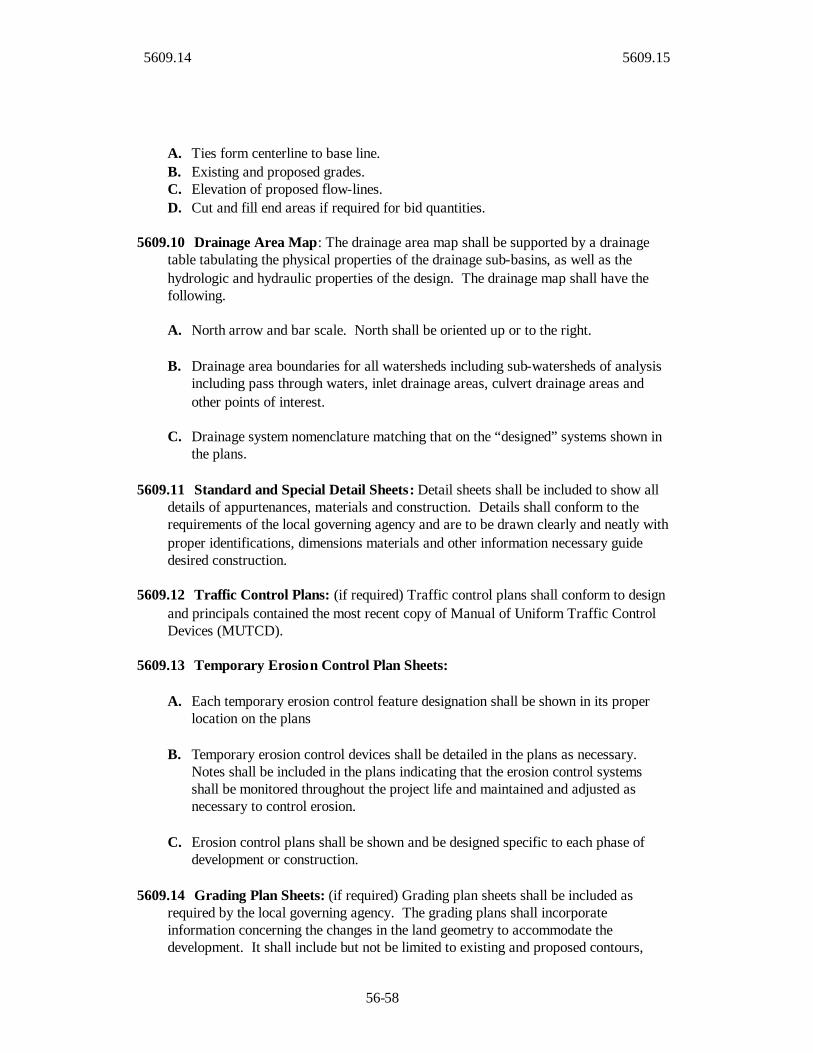
5609.14 5609.15
56-58
A. Ties form centerline to base line.B. Existing and proposed grades.C. Elevation of proposed flow-lines.D. Cut and fill end areas if required for bid quantities.
5609.10 Drainage Area Map: The drainage area map shall be supported by a drainagetable tabulating the physical properties of the drainage sub-basins, as well as thehydrologic and hydraulic properties of the design. The drainage map shall have thefollowing.
A. North arrow and bar scale. North shall be oriented up or to the right.
B. Drainage area boundaries for all watersheds including sub-watersheds of analysisincluding pass through waters, inlet drainage areas, culvert drainage areas andother points of interest.
C. Drainage system nomenclature matching that on the “designed” systems shown inthe plans.
5609.11 Standard and Special Detail Sheets: Detail sheets shall be included to show alldetails of appurtenances, materials and construction. Details shall conform to therequirements of the local governing agency and are to be drawn clearly and neatly withproper identifications, dimensions materials and other information necessary guidedesired construction.
5609.12 Traffic Control Plans: (if required) Traffic control plans shall conform to designand principals contained the most recent copy of Manual of Uniform Traffic ControlDevices (MUTCD).
5609.13 Temporary Erosion Control Plan Sheets:
A. Each temporary erosion control feature designation shall be shown in its properlocation on the plans
B. Temporary erosion control devices shall be detailed in the plans as necessary.Notes shall be included in the plans indicating that the erosion control systemsshall be monitored throughout the project life and maintained and adjusted asnecessary to control erosion.
C. Erosion control plans shall be shown and be designed specific to each phase ofdevelopment or construction.
5609.14 Grading Plan Sheets: (if required) Grading plan sheets shall be included asrequired by the local governing agency. The grading plans shall incorporateinformation concerning the changes in the land geometry to accommodate thedevelopment. It shall include but not be limited to existing and proposed contours,

5609.14 5609.15
56-59
building elevations, curb elevations, retaining wall elevations and other informationpertinent to the site.
5609.15 Property Line and Easement Sheets: Separate property line and easementsheets may be required by the local governing agency. The information on this sheetshall be sufficient to display the existing and proposed property line and easementchanges relative to the project.

56-60
This page intentionally left blank

56-61
TABLES

56-62
This page intentionally left blank

56-63
Con- Date Max.USGS tributing of Max. Max. Discharge Period
I.D. Station Station Drainage Recorded Recorded per Basin of Refer-# Number Name Area Discharge Discharge Area Record ences
(sq. miles) (cfs) (cfs/acre) (Water Yr.)
Kansas City Metropolitan Area, Missouri and Kansas1. 06821130 First Creek near Nashua 0.55 18-May-74 1,250 3.6 1959-84 1,72. -- Turkey Creek trib. at Carter St. at Merriam, Ks. 0.82 12-Sep-77 1,200 2.3 -- 33. -- Little Blue River trib. at Noland Road at Independence, Mo. 0.83 12-Sep-77 2,330 4.4 -- 34. -- Rock Creek at Woodson and Martway St. at Mission, Ks. 1.15 12-Sep-77 1,980 2.7 -- 35. -- Tucker Creek at Highway FF near Grain Valley, Mo. 1.45 12-Sep-77 1,890 2.0 -- 36. -- Brush Creek at 75th and Nall at Prairie Village, Ks. 1.51 12-Sep-77 3,000 3.1 -- 37. -- White Oak Creek at Raytown, Mo. (Raytown Road) 1.78 12-Sep-77 2,290 2.0 -- 38. -- Cedar Creek at Lee's Summit, Mo. (Chicago-Rock Island and Pacific RR) 1.84 12-Sep-77 2,410 2.0 -- 39. 06893710 Cates Branch near Liberty, Mo. (Sherril Drive) 1.95 12-Sep-77 2,480 2.0 -- 310. -- Mill Creek near Independence, Mo. (Courtney Road) 1.95 12-Sep-77 2,240 1.8 -- 311. -- Rock Creek at Sheridan Road at Fairway, Ks. 3.04 12-Sep-77 4,900 2.5 -- 312. -- Blue River trib. at Bannister Road near Kansas City, Mo. (U.S. Hwy 71) 3.38 13-Sep-77 4,040 1.9 -- 313. 06893600 Rock Creek at Independence, Mo. 5.2 12-Sep-77 7,760 2.3 1967-75 3,714. -- Brush Creek at 73rd St. and Mission Hills, Ks. 5.84 12-Sep-77 14,400 3.9 -- 315. 06893570 Round Grove Creek at Raytown Road at Kansas City, Mo. 5.87 Sep-77 13,200 3.5 316. 06892800 Turkey Creek at Merriam, Ks. (67th St.) 6.76 12-Sep-77 5,300 1.2 1974-86 3,717. -- Turkey Creek at Merriam, Ks. (63rd St.) 7.84 12-Sep-77 6,490 1.3 -- 318. 06893560 Brush Creek at Main St. at Kansas City, Mo. 14.89 12-Sep-77 17,600 1.8 1971-79 3,719. 06894500 East Fork Fishing River at Excelsior Springs, Mo. 20 6-Jul-51 12,000 0.9 1951-72 1,2,720. 06892940 Turkey Creek at Kansas City, Ks. (State Hwy. 10) 22.3 1-May-83 12,500 0.9 1974-87 3,721. 06893350 Tomahawk Creek near Overland Park, Ks. 23.9 13-Aug-82 8,250 0.5 1970-82 422. 06893300 Indian Creek at Overland Park, Ks. (Marty St.) 26.6 9-Jun-84 12,800 0.8 1964-01 423. 06894680 Sni-A-Bar Creek near Tarsney, Mo. (Colburn Road) 29.1 12-Sep-77 15,700 0.8 1970-79 3,724. -- Fishing Creek near Kearney, Mo. 39.4 22-Jun-47 30,000 1.2 -- 225. 06893080 Blue River near Stanley, Ks. 46 15-May-90 20,200 0.7 1970-01 426. 06893793 Little Blue River (below Longview Road Dam) at Kansas City, Mo. 50.7 13-Aug-82 18,700 0.6 1967-99 1,3,727. " " " " (2nd highest peak) 50.7 13-Sep-77 18,100 0.6 " " 1,3,7
Kansas, outside the Kansas City Metropolitan Area28. -- Dry Walnut Creek trib. near Great Bend 1.19 15-Jun-81 3,080 4.0 -- 429. 06889100 Soldier Creek near Goff 2.06 10-May-70 7,080 5.4 -- 2,430. -- Dry Walnut Creek trib. near Great Bend 2.28 15-Jun-81 5,720 3.9 -- 431. 06912300 Dragoon Creek trib. near Lyndon 3.76 11-Jun-81 8,200 3.4 -- 432. 06879650 Kings Creek near Manhattan 4.09 13-May-95 10,200 3.9 -- 433. 07166700 Burnt Creek at Reece 8.85 9-Jun-65 20,500 3.6 -- 2,434. -- Mill Creek near Alta Vista 18.7 1951 19,800 1.7 -- 635. 07184600 Fly Creek near Faulkner 27 3-Jul-76 28,000 1.6 1957-77 436. 06815600 Wolf River near Hiawatha 41 9-Aug-68 40,000 1.5 -- 437. 07179600 Four Mile Creek near Council Grove 55 26-Jun-69 68,100 1.9 1964-77 438. 07181500 Middle Creek near Elmdale 92 27-Jun-69 60,000 1.0 '17, 38-90 4
Missouri, outside the Kansas City Metropolitan Area39. -- Nemo Branch at Nemo 0.52 30-May-56 1,950 5.9 -- 240. 07011500 Green Acre Branch near Rolla 0.62 9-Jun-50 1,900 4.8 1948-75 1,2,741. -- Boney Draw at Rockport 0.76 18-Jul-65 5,080 10.4 -- 242. -- Clear Creek tributary near Holt 6.52 22-Jun-47 14,000 3.4 -- 243. 07019790 Plattin Creek at Plattin 65.8 Jun-64 36,800 0.9 1966-72 2,7
Midwest, outside Missouri and Kansas.44. -- East Fork Big Creek near Bowlegs, Okla. 0.89 14-Apr-45 3,000 5.3 -- 245. -- Stratton Creek near Washta, Iowa 1.9 9-Aug-61 11,000 9.0 -- 246. -- West Fork Big Blue River trib. near York, Nebr. 6.9 9-Jul-50 23,000 5.2 -- 247. 08057140 Cottonwood Creek at Forest Lane, Dallas, Tx. 8.5 28-Apr-66 17,600 3.2 1962-78 5,748. -- Ranch Creek near Halley, Okla. 17.1 4-Sep-40 32,400 3.0 -- 2
References Cited:1. Alexander and Wilson. Technique for Estimating the 2-to 500-Year Flood Discharges on Unregulated Streams
in Rural Missouri. USGS WRIR 95-4231. 19952. Crippen and Bue. Maximum Floodflows in the Conterminous United States. USGS WSP 1887. 1977.3. Hauth. Floods in Kansas City, Missouri and Kansas, September 12-13, 1977 . USGS Prof. Paper 1169. 1981.4. Rasmussen and Perry. Estimate of Peak Streamflows for Unregulated Rural Streams in Kansas . USGS WRIR 00-4079. 2000.5. Sauer et al. Flood Characteristics of Urban Watersheds in the United States. USGS WSP 2207. 1983.6. USGS. Kansas-Missouri - Floods of July 1951. USGS WSP 1139. 1952.7. USGS. Surface-Water Data for the Nation. Peak flow database at http://waterdata.usgs.gov/nwis/sw. Queried January 2003.
Table 5602-1Documented Extreme Stream Flows
In the Kansas City Area and Surrounding Region
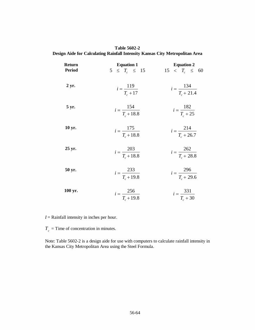
56-64
Table 5602-2Design Aide for Calculating Rainfall Intensity Kansas City Metropolitan Area
ReturnPeriod
Equation 1155 cT
Equation 26015 cT
2 yr.
17119
cT
i4.21
134
cT
i
5 yr.
8.18154
cT
i25
182
cT
i
10 yr.
8.18175
cT
i7.26
214
cT
i
25 yr.
8.18203
cT
i8.28
262
cT
i
50 yr.
8.19233
cT
i6.29
296
cT
i
100 yr.
8.19256
cT
i30
331
cT
i
I = Rainfall intensity in inches per hour.
cT = Time of concentration in minutes.
Note: Table 5602-2 is a design aide for use with computers to calculate rainfall intensity inthe Kansas City Metropolitan Area using the Steel Formula.

Table 5603-1MANNING’S ROUGHNESS COEFFICIENT
Type of Channel n
Closed ConduitsReinforced Concrete Pipe (RCPs) .............................................................................................0.013Reinforced Concrete Elliptical Pipe ..........................................................................................0.013Corrugated Metal Pipe (CMPs):
2⅔ x ½in. Annular or Helical Corrugations unpaved - plain ................................................0.0242⅔ x ½in. Annular or Helical Corrugations paved invert .....................................................0.0213x1 in. Annular or Helical Corrugations unpaved - plain .....................................................0.0273x1 in. Annular or Helical Corrugations paved invert ..........................................................0.0236x2 in. Corrugations unpaved - plain ...................................................................................0.0336x2 in. Corrugations paved invert ........................................................................................0.02824” diameter and smaller with Helical Corrugations.*.............................................................0.020Vitrified Clay Pipe .............................................................................................................. 0.013Asbestos Cement Pipe.........................................................................................................0.012
Open Channels (Lined)Gabions.........................................................................................................................................0.025Concrete
Trowel Finish ...........................................................................................................................0.013Float Finish............................................................................................................................... 0.015Unfinished................................................................................................................................0.017
Concrete, bottom float finished, with sides ofDressed Stone ...........................................................................................................................0.017Random Stone ..........................................................................................................................0.020Cement Rubble masonry ...........................................................................................................0.025Dry Rubble or Riprap................................................................................................................0.030
Gravel bottom, side ofRandom Stone ..........................................................................................................................0.023Riprap ...................................................................................................................................... 0.033
Grass (Sod) ................................................................................................................................... 0.030Riprap...........................................................................................................................................0.035Grouted Riprap..............................................................................................................................0.030Open Channels (Unlined) Excavated or Dredged
Earth, straight and uniform........................................................................................................0.027Earth, winding and sluggish ...................................................................................................... 0.035Channels, not maintained, weeds & brush uncut ........................................................................0.090
Natural StreamClean stream, straight................................................................................................................0.030Stream with pools, sluggish reaches, heavy underbrush .............................................................0.100
Flood PlainsGrass, no brush ......................................................................................................................... 0.030With some brush ......................................................................................................... 0.090
Street Curbing................................................................................................ .................. 0.014
*Allowed only when the pipe length between structures is at least 20 pipe diameters.
56-65
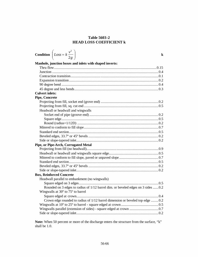
56-66
Table 5603-2HEAD LOSS COEFFICIENT k
Condition
gv
kLoss2
2
k
Manhole, junction boxes and inlets with shaped inverts:Thru flow..............................................................................................................0.15Junction .................................................................................................................. 0.4Contraction transition................................ ..............................................................0.1Expansion transition................................................................................................0.290 degree bend ........................................................................................................0.445 degree and less bends.......................................................................................... 0.3
Culvert inlets:Pipe, Concrete
Projecting from fill, socket end (grove end) ..............................................................0.2Projecting from fill, sq. cut end ................................................................................0.5Headwall or headwall and wingwalls
Socket end of pipe (groove end) .......................................................................... 0.2Square edge........................................................................................................0.5Round (radius=1/12D) .......................................................................................0.2
Mitered to conform to fill slope................................................................................0.7Standard end section................................................................................................0.5Beveled edges, 33.7º or 45º bevels ........................................................................... 0.2Side or slope-tapered inlet........................................................................................0.2
Pipe, or Pipe-Arch, Corrugated MetalProjecting from fill (no headwall)................................ .............................................0.9Headwall or headwall and wingwalls square edge................................ .....................0.5Mitered to conform to fill slope, paved or unpaved slope .......................................... 0.7Standard end section................................................................................................0.5Beveled edges, 33.7º or 45º bevels ........................................................................... 0.2Side or slope-tapered inlet........................................................................................0.2
Box, Reinforced ConcreteHeadwall parallel to embankment (no wingwalls)
Square edged on 3 edges................................................................ .....................0.5Rounded on 3 edges to radius of 1/12 barrel dim. or beveled edges on 3 sides ......0.2
Wingwalls at 30º to 75º to barrelSquare edged at crown........................................................................................0.4Crown edge rounded to radius of 1/12 barrel dimension or beveled top edge ........0.2
Wingwalls at 10º to 25º to barrel - square edged at crown ........................................0.5Wingwalls parallel (extension of sides) - square edged at crown ...............................0.7Side or slope-tapered inlet........................................................................................0.2
Note: When 50 percent or more of the discharge enters the structure from the surface, “k”shall be 1.0.

56-67
Table 5605-1CRITICAL SHEAR STRESSES FOR CHANNEL MATERIALS
(Solely for use in stream assessments as described in chapter 5605.5.Not to be used as allowable shear stresses for design)
psfGranular MaterialBoulders (100 cm) 20.295Boulders (75 cm) 15.222Boulders (50 cm) 10.148Boulders (25.6 cm) 5.196Rip Rap 3.132Cobbles (6.4 cm) 1.299Cobbles and shingles 1.100Cobbles and shingles, clear water 0.910Coarse sand (1mm) 0.015Coarse sand (1mm) 0.015Coarse gravel, noncolloidal (GW), clear water 0.300Coarse gravel, noncolloidal, (GW) 0.670Gravel (2cm) 0.406Fine gravel 0.320Fine gravel, clear water 0.075Fine sand (0.125 mm) 0.002Fine sand (0.125 mm) (SP) 0.002Fine sand (SW), (SP), colloidal 0.075Fine sand, colloidal, (SW), (SP), clear water 0.027Graded loam to cobbles, noncolloidal (GM) 0.660Graded loam to cobbles, noncolloidal,(GM), clear water 0.380Graded silts to cobbles, colloidal (GC) 0.800Graded silts to cobbles, colloidal, (GC), clear water 0.430
Fine GrainedResistant cohesive (CL), (CH) 1.044Stiff clay, very colloidal, (CL) 0.460Stiff clay, very colloidal, (CL), clear water 0.260Moderate cohesive (ML-CL) 0.104Ordinary firm loam (CL-ML) 0.150Ordinary firm loam, (CL-ML), clear water 0.075Alluvial silts, colloidal (CL-ML) 0.460

56-68
Table 5605-1CRITICAL SHEAR STRESSES FOR CHANNEL MATERIALS
(Solely for use in stream assessments as described in chapter 5605.5.Not to be used as allowable shear stresses for design)
Alluvial silts, colloidal,(CL-ML), clear water 0.260Alluvial silts, noncolloidal (ML) 0.150Alluvial silts, noncolloidal, (ML), clear water 0.048
Sandy loam, noncolloidal (ML) 0.075Sandy loam, noncolloidal, (ML), clear water 0.037Silt loam, noncolloidal (ML) 0.110Silt loam, noncolloidal, (ML), clear water 0.048
Shales and hardpans 0.67
OthersJute net 0.46Plant cuttings 2.09Well established dense vegetation to the normal low water 2.16Geotextile (synthetic) 3.01Large Woody Debris 3.13
Note: For non-cohesive soils, the table values are based on spherical particles and Shieldequation, as follows: τc = Θ(γs -γ) D where γs is the specific weight of sediment (165 pcf),γ is specific weight of water, D is the reference particle size, and Θ is the Shield’s parameter (0.06 for gravel to cobble, 0.044 for sand). For cohesive soils the values arebased on limited testing as reported in Chow (1988) and USDA (2001).

56-69
Project: ____________________________________________________
Stream Name and Location: ____________________________________
Evaluated by: _______________Firm: ______________ Date:_________
Table 5605-2CHANNEL CONDITION SCORING MATRIX
(adapted from Johnson, et al 1999 )
StabilityIndicator Good (1) Fair (2) Poor (3)
Score(S)
Weight(W)
RatingS*W=
(R)Bank soiltexture andcoherence
cohesive materials,clay (CL), silty clay(CL-ML), massivelimestone,continuous concrete,clay loam (ML-CL),silty clay loam (ML-CL), thinly bedlimestone
sandy clay (SC),sandy loam (SM),fractured thinlybedded limestone
non-cohesivematerials, shale inbank, (SM), (SP),(SW), (GC), (GM),(GP), (GW)
0.6
Average bankslope angle
slopes ≤2:1 on oneor occasionally bothbanks
slopes up to1.7:1(60 )̊ common on oneor both banks
bank slopes over60 o̊n one or bothbanks
0.6
Average bankheight
less than 6 feet greater than 6 and lessthan 15 feet
greater than 15 feet 0.8
Vegetativebankprotection
wide to medium bandof woody vegetationwith 70-90% plantdensity and cover.Majority arehardwood, deciduoustrees with well-developed understorylayer, minimal rootexposure
narrow bank ofwoody vegetation,poor species diversity,50-70% plant density,most vegetation ontop of bank and notextending onto bankslope, some treesleaning over bank,root exposurecommon
thin or no band ofwoody vegetation,poor health,monoculture, manytrees leaning overbank, extensive rootexposure, turf grassto edge of bank
0.8
Bank cutting little to some evidentalong channel bendsand at prominentconstrictions, someraw banks up to 4foot
Significant andfrequent. Cut banks 4feet high. Root matoverhangs common.
Almost continuouscut banks, someover 4 feet high.Undercut trees withsod-rootmatoverhangs common.Bank failuresfrequent
0.4
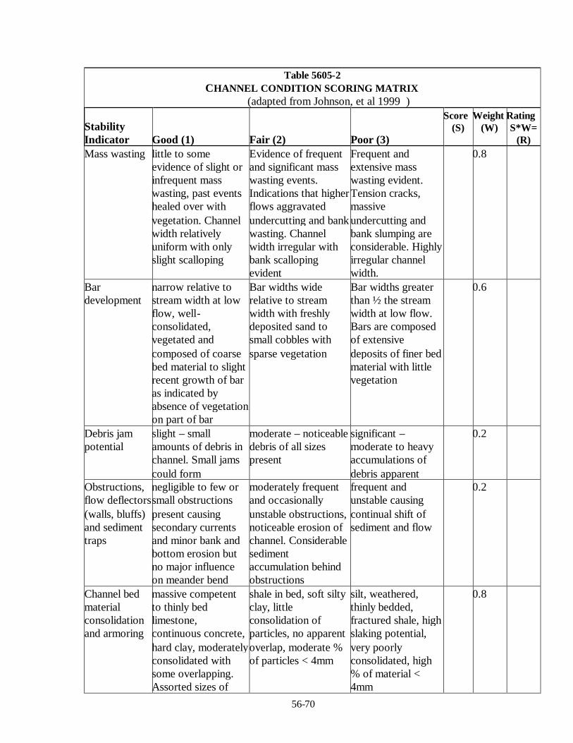
56-70
Table 5605-2CHANNEL CONDITION SCORING MATRIX
(adapted from Johnson, et al 1999 )
StabilityIndicator Good (1) Fair (2) Poor (3)
Score(S)
Weight(W)
RatingS*W=
(R)Mass wasting little to some
evidence of slight orinfrequent masswasting, past eventshealed over withvegetation. Channelwidth relativelyuniform with onlyslight scalloping
Evidence of frequentand significant masswasting events.Indications that higherflows aggravatedundercutting and bankwasting. Channelwidth irregular withbank scallopingevident
Frequent andextensive masswasting evident.Tension cracks,massiveundercutting andbank slumping areconsiderable. Highlyirregular channelwidth.
0.8
Bardevelopment
narrow relative tostream width at lowflow, well-consolidated,vegetated andcomposed of coarsebed material to slightrecent growth of baras indicated byabsence of vegetationon part of bar
Bar widths widerelative to streamwidth with freshlydeposited sand tosmall cobbles withsparse vegetation
Bar widths greaterthan ½ the streamwidth at low flow.Bars are composedof extensivedeposits of finer bedmaterial with littlevegetation
0.6
Debris jampotential
slight – smallamounts of debris inchannel. Small jamscould form
moderate – noticeabledebris of all sizespresent
significant –moderate to heavyaccumulations ofdebris apparent
0.2
Obstructions,flow deflectors(walls, bluffs)and sedimenttraps
negligible to few orsmall obstructionspresent causingsecondary currentsand minor bank andbottom erosion butno major influenceon meander bend
moderately frequentand occasionallyunstable obstructions,noticeable erosion ofchannel. Considerablesedimentaccumulation behindobstructions
frequent andunstable causingcontinual shift ofsediment and flow
0.2
Channel bedmaterialconsolidationand armoring
massive competentto thinly bedlimestone,continuous concrete,hard clay, moderatelyconsolidated withsome overlapping.Assorted sizes of
shale in bed, soft siltyclay, littleconsolidation ofparticles, no apparentoverlap, moderate %of particles < 4mm
silt, weathered,thinly bedded,fractured shale, highslaking potential,very poorlyconsolidated, high% of material <4mm
0.8
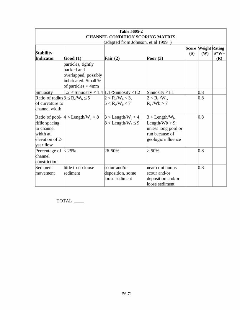
56-71
Table 5605-2CHANNEL CONDITION SCORING MATRIX
(adapted from Johnson, et al 1999 )
StabilityIndicator Good (1) Fair (2) Poor (3)
Score(S)
Weight(W)
RatingS*W=
(R)particles, tightlypacked andoverlapped, possiblyimbricated. Small %of particles < 4mm
Sinuosity 1.2 ≤Sinuosity ≤1.4 1.1<Sinuosity <1.2 Sinuosity <1.1 0.8Ratio of radiusof curvature tochannel width
3 ≤Rc/Wb ≤5 2 < Rc/Wb < 3,5 < Rc/Wb < 7
2 < Rc /Wb,Rc /Wb > 7
0.8
Ratio of pool-riffle spacingto channelwidth atelevation of 2-year flow
4 ≤Length/Wb < 8 3 ≤Length/Wb < 4,8 < Length/Wb ≤9
3 < Length/Wb,Length/Wb > 9,unless long pool orrun because ofgeologic influence
0.8
Percentage ofchannelconstriction
< 25% 26-50% > 50% 0.8
Sedimentmovement
little to no loosesediment
scour and/ordeposition, someloose sediment
near continuousscour and/ordeposition and/orloose sediment
0.8
TOTAL ____
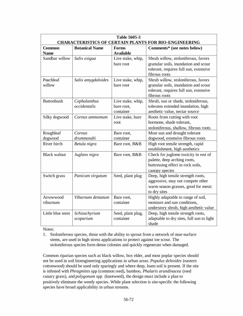
56-72
Table 5605-3CHARACTERISTICS OF CERTAIN PLANTS FOR BIO-ENGINEERING
CommonName
Botanical Name FormsAvailable
Comments* (see notes below)
Sandbar willow Salix exigua Live stake, whip,bare root
Shrub willow, stoloniferous, favorsgranular soils, inundation and scourtolerant, requires full sun, extensivefibrous roots
Peachleafwillow
Salix amygdaloides Live stake, whip,bare root
Shrub willow, stoloniferous, favorsgranular soils, inundation and scourtolerant, requires full sun, extensivefibrous roots
Buttonbush Cephalanthusoccidentalis
Live stake, whip,bare root,container
Shrub, sun or shade, stoloniferous,tolerates extended inundation, highaesthetic value, nectar source
Silky dogwood Cornus ammomum Live stake, bareroot
Roots from cutting with roothormone, shade tolerant,stoloniferous, shallow, fibrous roots
Roughleafdogwood
Cornusdrummondii
Bare root,container
Most sun and drought tolerantdogwood, extensive fibrous roots
River birch Betula nigra Bare root, B&B High root tensile strength, rapidestablishment, high aesthetics
Black walnut Juglans nigra Bare root, B&B Check for juglome toxicity in rest ofpalette, deep arching roots,buttressing effect in rock soils,canopy species
Switch grass Panicum virgatum Seed, plant plug Deep, high tensile strength roots,aggressive, may out compete otherwarm season grasses, good for mesicto dry sites
Arrowwoodviburnum
Viburnum dentatum Bare root,container
Highly adaptable to range of soil,moisture and sun conditions,understory shrub, high aesthetic value
Little blue stem Schizachyriumscoparium
Seed, plant plug,container
Deep, high tensile strength roots,adaptable to dry sites, full sun to lightshade
Notes:1. Stoloniferous species, those with the ability to sprout from a network of near-surface
stems, are used in high stress applications to protect against toe scour. Thestoloniferous species form dense colonies and quickly regenerate when damaged.
Common riparian species such as black willow, box elder, and most poplar species shouldnot be used in soil bioengineering applications in urban areas. Populus deltoides (easterncottonwood) should be used only sparingly and where deep, loam soil is present. If the siteis infested with Phragmites spp (common reed), bamboo, Phalaris arundinacea (reedcanary grass), and polygonum spp (knotweed), the design must include a plan topositively eliminate the weedy species. While plant selection is site-specific the followingspecies have broad applicability in urban streams.
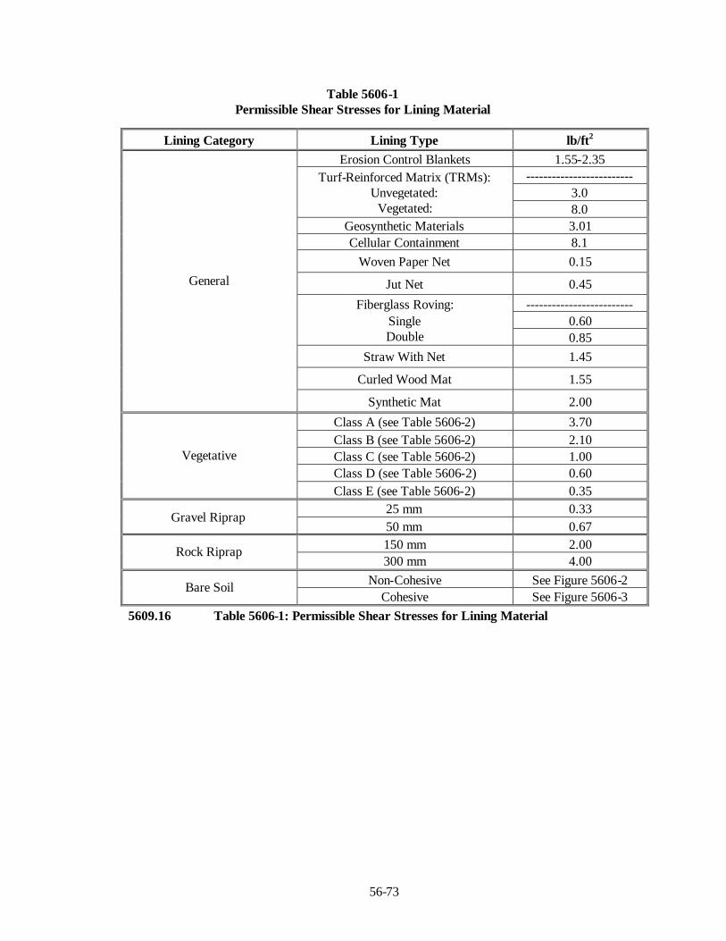
56-73
Table 5606-1Permissible Shear Stresses for Lining Material
5609.16 Table 5606-1: Permissible Shear Stresses for Lining Material
Lining Category Lining Type lb/ft2
Erosion Control Blankets 1.55-2.35-------------------------
3.0Turf-Reinforced Matrix (TRMs):
Unvegetated:Vegetated: 8.0
Geosynthetic Materials 3.01Cellular Containment 8.1
Woven Paper Net 0.15
Jut Net 0.45
-------------------------0.60
Fiberglass Roving:SingleDouble 0.85
Straw With Net 1.45
Curled Wood Mat 1.55
General
Synthetic Mat 2.00
Class A (see Table 5606-2) 3.70Class B (see Table 5606-2) 2.10Class C (see Table 5606-2) 1.00Class D (see Table 5606-2) 0.60
Vegetative
Class E (see Table 5606-2) 0.3525 mm 0.33
Gravel Riprap50 mm 0.67150 mm 2.00Rock Riprap300 mm 4.00
Non-Cohesive See Figure 5606-2Bare SoilCohesive See Figure 5606-3

56-74
Table 5606-2Classification of Vegetal Covers as to Degree of Retardance
RetardanceClass
Cover Condition
Weeping Love Grass Excellent stand, tall (average 760 mm)A
Yellow Bluestem Ischaemum Excellent stand, tall (average 910 mm)Kudzu Very dense growth, uncutBermuda Grass Good stand, tall (average 300 mm)Native Grass Mixture (little bluestem,bluestem, blue gamma, and other long andshort Midwest grasses)
(Good stand, unmowed)
Weeping lovegrass Good stand, tall (average 610 mm)Lespedeza sericea Good stand, not woody, tall (average 480
mm)Alfalfa Good stand, uncut (average 280 mm)Weeping lovegrass Good stand, unmowed (average 330 mm)Kudzu Dense growth, uncut
B
Blue Gamma Good stand, uncut (average 280 mm)Crabgrass Fair stand, uncut 250 to 1200 mmBermuda grass Good stand, mowed (average 150 mm)Common Lespedeza Good stand, uncut (average 280 mm)Grass-Legume mixture – summer(orchard grass, redtop, Italian ryerass, andcommon lespedeza)
(Good stand, uncut (150 to 200 mm)
Centipedegrass Very dense cover (average 150 mm)
C
Kentucky Bluegrass Good stand, headed (150 to 300 mm)Bermuda grass Good stand, cut to 60-mm heightCommon Lespedeza Excellent stand, uncut (average 110 mm)Buffalo grass Good stand, uncut (80 to 150 mm)Grass-legume mixture—fall, spring(orchard grass, redtop, Italian, ryegrass,and common lespedeza)
(Good stand, uncut (100 to 130 mm)
D
Lespedeza sericea After cutting to 50-mm height. Very goodstand before cutting
Bermuda grass Good stand, cut to height 40-mmEBermuda grass Burned stubble
Note: Covers classified have been tested in experimental channels. Covers were green and generallyuniform.

Energy Dissipation Countermeasure Functional Applications Suitable EnvironmentStream Instability
Vertical Control Horizontal Control DAM OUTLETS SMALL CULVERTS LARGE CULVERTS REFERENCESCheck Dams X O X X X 2,6Level Srpeaders X X O X O 1Hydraulic Jump Basins X X X X X 1,3Impact Baffle Basins X X X X X 1Plunge Pool and Plunge Basin X O X X X 1Slotted-Grating or Slotted Bucket Dissipators X X X O X 1Stilling Basins X O X X X 1,2,3,4,5,6Rock Revetment X X X X X 1,2,6Internal Pipe Rings X O NA X NA See Manufacturers Recommendations
SAMPLE REFERENCES
1. DESIGN OF SMALL DAMS 1987 UNITED STATES DEPARTMENT OF INTERIOR2. HEC 233. HYDRAULIC DESIGN OF STILLING BASINS AND ENERGY DISSIPATORS4. HEC-14 FHWA HYDRAULIC DESIGN OF ENERGY DISSIPATERS FOR CULVERTS AND CHANNELS5. U.S. ARMY CORPS OF ENGINEERS, 1994 HYDRAULIC DESIGN OF FLOOD CONTROL CHANNELS6. HYDRAULIC DESIGN SERIES (HDS-6)
NOTE: Other means may be used for Energy Dissipation and Stream Stability by designers as accepted by the local governing agency
LEGENDSUITABLE XMARGINAL O
Table 5606-3 Energy Dissipation Countermeasures

56-76
This page intentionally left blank

56-77
FIGURES

56-78
This page intentionally left blank
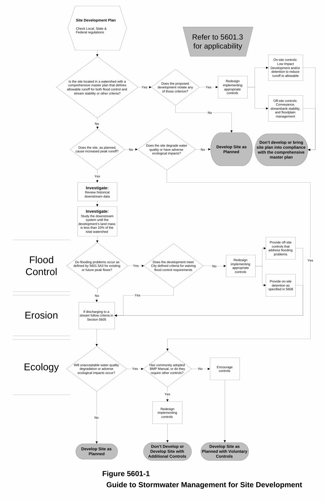
Site Development Plan
Check Local, State &Federal regulations
Is the site located in a watershed with acomprehensive master plan that defines
allowable runoff for both flood control and
stream stability or other criteria?
No
Does the site, as planned,cause increased peak runoff?
Do flooding problems occur asdefined by 5601.5A3 for existing
or future peak flows?
Yes
Does the proposeddevelopment violate any
of those criterion?
Yes Yes
No
No
If discharging to astream follow criteria in
Section 5605
No
Will unacceptable water qualitydegradation or adverse
ecological impacts occur?
Develop Site asPlanned
Develop Site asPlanned
No
Does the development meetCity defined criteria for waiving
flood control requirements
Yes
Yes
No
Provide off-site
controls thataddress flooding
problems
Provide on-site
detention asspecified in 5608
On-site controls:
Low Impact
Development and/ordetention to reduce
runoff to allowable
Off-site controls:Conveyance,
streambank stability,and floodplain
management
Has community adoptedBMP Manual, or do they
require other controls?
Encouragecontrols
Yes No
Redesignimplementing
controls
Yes
Don’t Develop orDevelop Site with
Additional Controls
Don’t develop or bringsite plan into compliancewith the comprehensive
master plan
Figure 5601-1Guide to Stormwater Management for Site Development
Flood
Control
Refer to 5601.3
for applicability
Investigate:Review historical
downstream data
Investigate:Study the downstream
system until the
development’s land massis less than 10% of the
total watershed
Erosion
Ecology
Does the site degrade water
quality or have adverseecological impacts?
No
Yes
Redesign
implementing
appropriatecontrols
Redesign
implementingappropriate
controls
Develop Site asPlanned with Voluntary
Controls
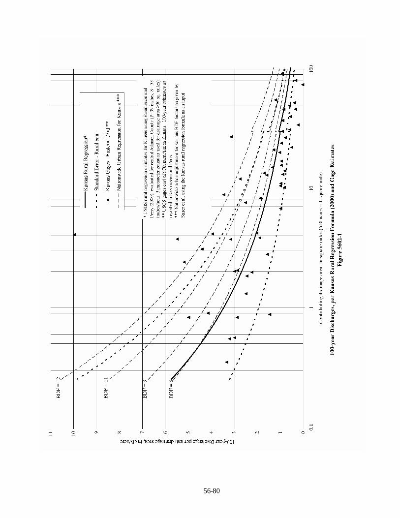
56-80
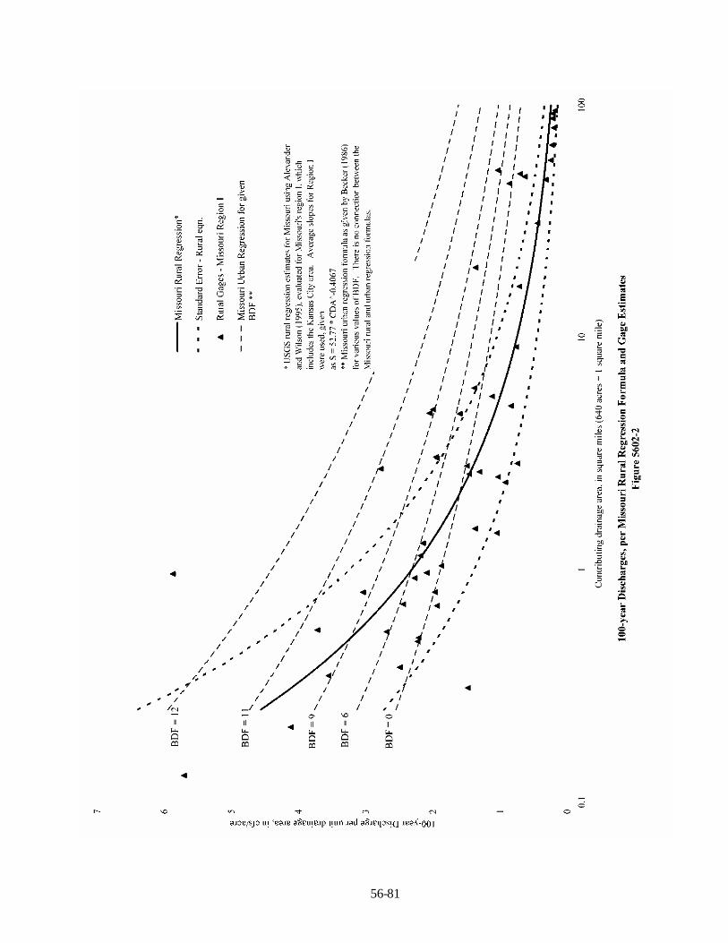
56-81
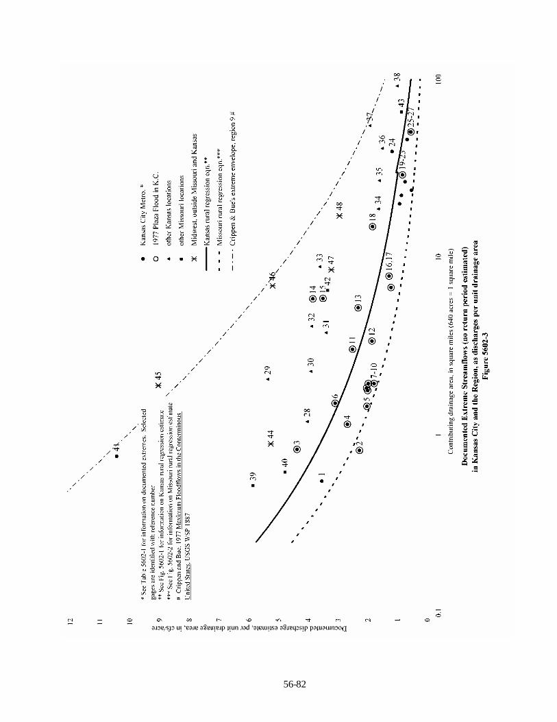
56-82

56-83

56-84
Figure 5602-5

56-85
Figure 5602-6
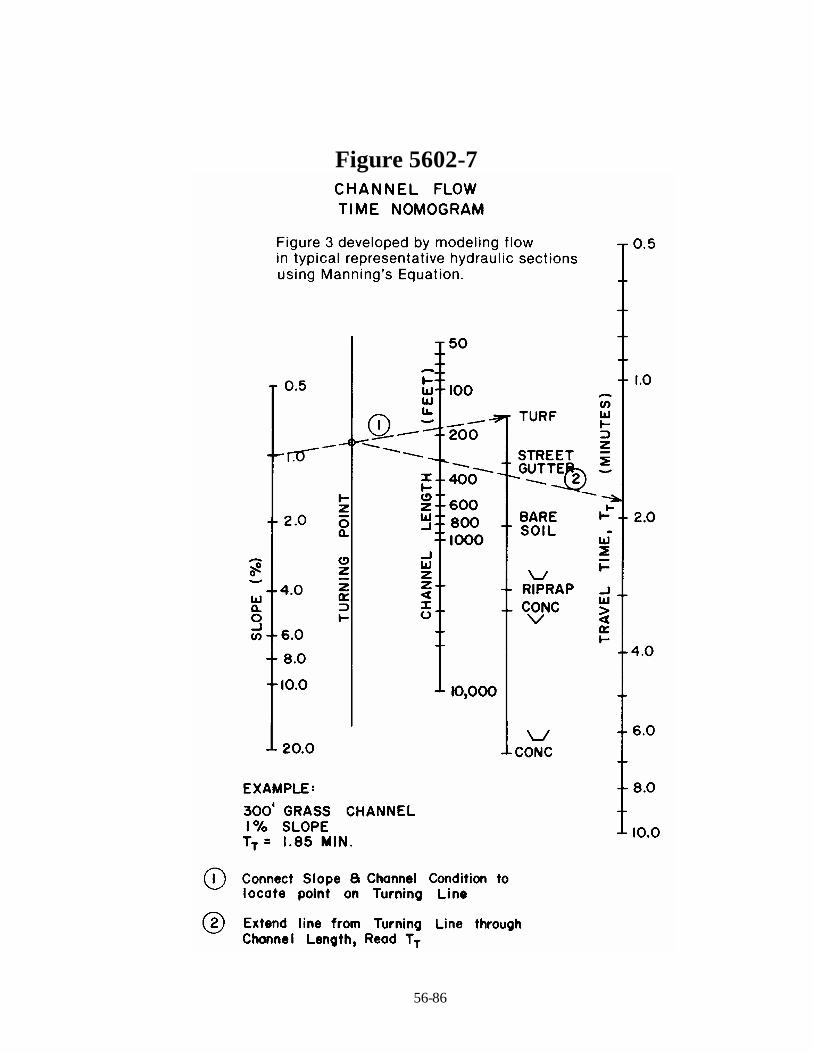
56-86
Figure 5602-7
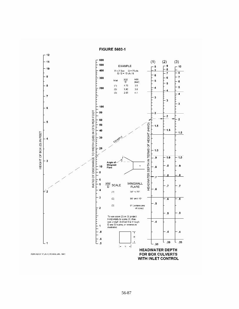
56-87

56-88
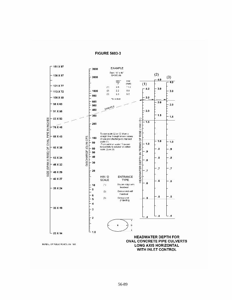
56-89
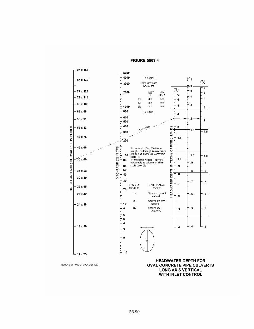
56-90
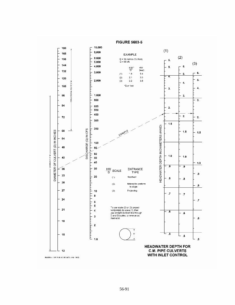
56-91
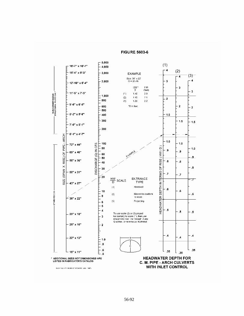
56-92

56-93

56-94

56-95
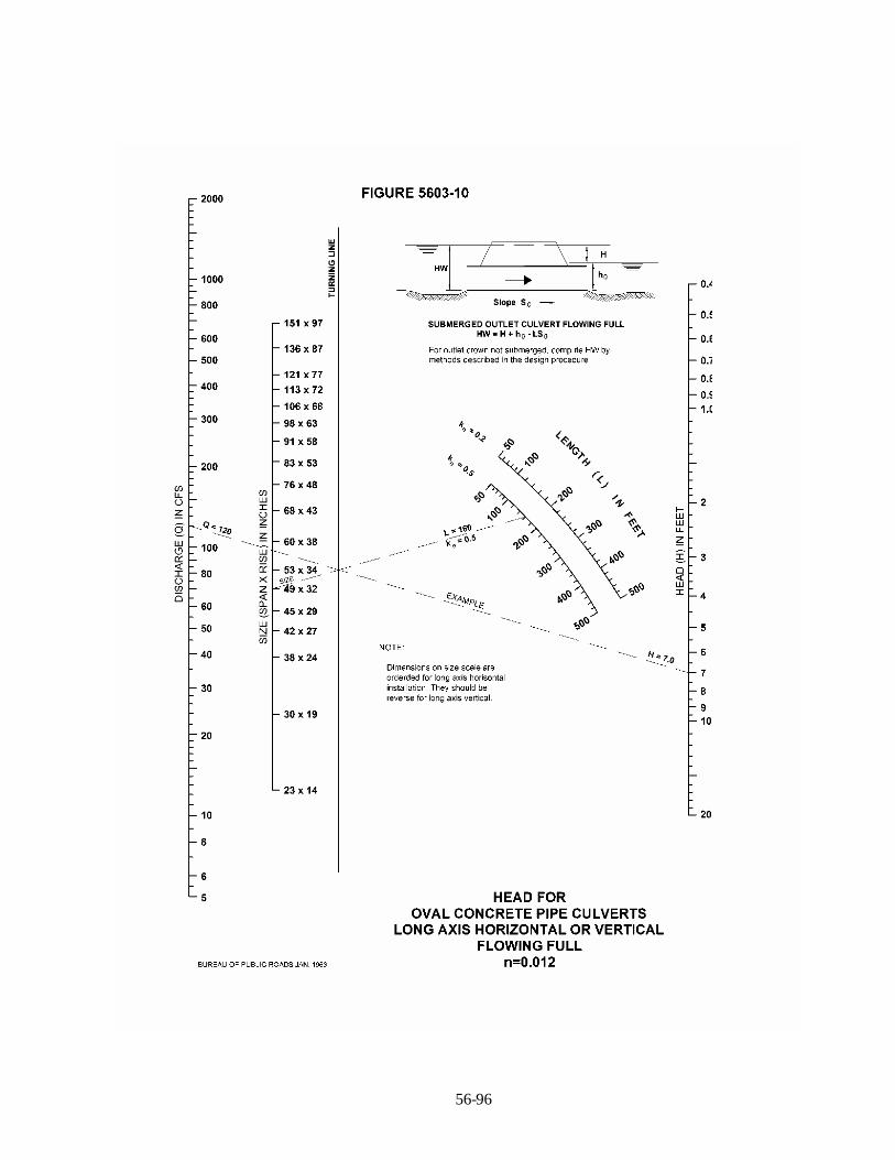
56-96
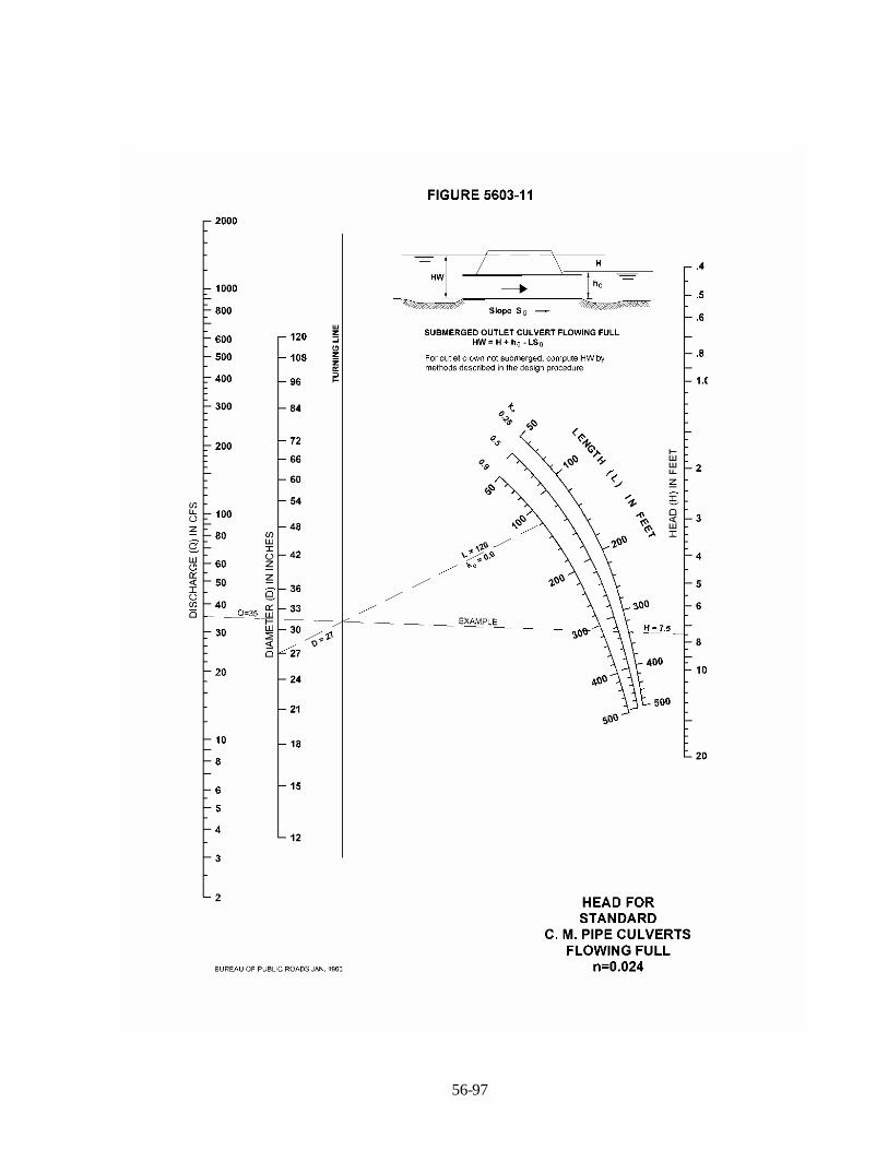
56-97

56-98

56-99
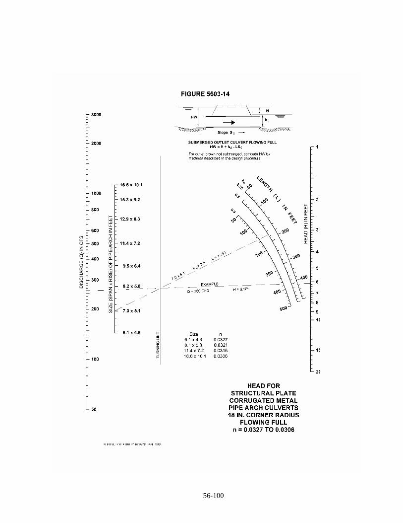
56-100


56-102
Curb Inlet Intercept Equations:
1.“For any given set of conditions (curb type, inlet length, street grade and cross-slope), therelationship between the captured discharge and the total discharge can be approximatedsatisfactorily by an equation of the form
ot
oa
otoao
ott
c QQforQQQQQQQ
QQforQ
Qexp1)(
in which Qo and Qa are constants. The constant Qo represents the largest discharge that is capturedcompletely, and the constant Qa represents the upper limit on the captured discharge, which isapproached asymptotically with increasing total discharge. For a particular curb type and streetcross-slope, Qo and Qa vary with inlet length (Lo) and street grade (So) according to the formulas
xooo SLbaQ ))((
xooa SLdcQ ))((
in which a, b, c, d and x are constants. Table 2 shows these constants in U.S. customary units.
Table 1. Values of Coefficients and Exponent
Curb Type Sx,% a b c d xCG-1 (B) 2 1.0 0 3.2 1.7 -0.5CG-1 (B) 4 1.5 0.5 2.6 1.9 -0.5CG-2 (A) 2 -0.4 0.1 3.5 0.8 -0.7CG-2 (A) 4 -0.3 0.3 4.3 2.5 -0.8
1.”Hydraulic Performance of Set-Back Curb Inlets”, McEnroe et al., University of Kansas, 1998.

56-103
The following is a Microsoft Visual Basic function that can be added to a Microsoft Excel (97 orlater) worksheet or template for inlet intercept calculations.
Function InletIntercept(slope, Qt, Optional CrossSlope = 2, _Optional Length = 4#, Optional CurbType = "A", _Optional Metric = False)
'' InletIntercept Macro' Determine the intercept ratio for setback curb' inlets given length of opening, q, slope and cross slope' All inputs in english units.' Function written 04/19/1999 by Michael S. Ross'Dim a As Double, b As Double, c As Double, d As DoubleDim x As Double, Qo As Double, Qa As DoubleDim strAlert As String
CurbType = UCase(CurbType)If CurbType <> "A" And CurbType <> "B" Then
strAlert = "Curb type must be one of 'A' or 'B'. 'A' assumed. "CurbType = "A"
End IfIf slope >= -0.00001 And slope <= 0.00001 Then
InletIntercept = QtElseSelect Case CurbTypeCase "A"
Select Case CrossSlopeCase 2
If Metric Thena = -0.12b = 0.03c = 1.07d = 0.24x = -0.7
Elsea = -0.4b = 0.1c = 3.5d = 0.8x = -0.7
End IfCase 4
If Metric Thena = -0.09b = 0.09c = 1.31d = 0.76x = -0.8
Elsea = -0.3b = 0.3c = 4.3d = 2.5x = -0.8
End IfCase Else
strAlert = strAlert & "Cross slope must be either 2% or 4%," & _"other cross slopes were not modelled. Assuming 2%. "
If Metric Thena = -0.12b = 0.03c = 1.07d = 0.24x = -0.7
Elsea = -0.4b = 0.1c = 3.5d = 0.8x = -0.7
End IfEnd Select
Case "B"
Select Case CrossSlopeCase 2

56-104
If Metric Thena = 0.3b = 0#c = 0.98d = 0.52x = -0.5
Elsea = 1#b = 0#c = 3.2d = 1.7x = -0.5
End IfCase 4
If Metric Thena = 0.46b = 0.15c = 0.79d = 0.58x = -0.5
Elsea = 1.5b = 0.5c = 2.6d = 1.9x = -0.5
End IfCase Else
strAlert = strAlert & "Cross slope must be either 2% or 4%," & _"other cross slopes were not modelled. Assuming 2%. "
a = 1#b = 0#c = 3.2d = 1.7x = -0.5
End SelectEnd SelectQo = (a + (b * Length)) * (slope) ^ xQa = (c + (d * Length)) * (slope) ^ xIf Qt <= Qo Then
InletIntercept = QtElse
InletIntercept = Qo + (Qa - Qo) * (1 - Exp(-((Qt - Qo) / (Qa - Qo))))End IfEnd IfIf strAlert <> "" Then MsgBox strAlert, vbExclamationEnd Function

56-105
Figure 5604-2Type CG-1 Curb, Sx=2%, So=0.5 %
0.00
1.00
2.00
3.00
4.00
5.00
6.00
7.00
8.00
9.00
10.00
11.00
0.00 2.00 4.00 6.00 8.00 10.00 12.00
Total Discharge, cfs
Inle
tCap
acity
,cfs
(80%
ofth
eore
tical
)
Inlet Lengths, ft
12
108
76
5 4
Allo
wab
leG
utte
rSp
read
3.18
cfs
Theo
retic
alC
aptu
red
Dis
char
ge
5
10
7
12
4
6
8
11
1
2
3
9
13
Figure 5604-3 (DESIGN EXAMPLE)Type CG-1 Curb, Sx=2%, So=1.0 %
0.00
1.00
2.00
3.00
4.00
5.00
6.00
7.00
8.00
9.00
10.00
0.00 2.00 4.00 6.00 8.00 10.00 12.00
Total Discharge, cfs
Inle
tCap
acity
,cfs
(80%
oft
heor
etic
al)
10 8
7
4
6
5
12
Inlet Lengths, ft
Allo
wab
leG
utte
rS
prea
d4.
5cf
s
Theo
retic
alC
aptu
red
Dis
char
ge
5
10
7
12
4
6
8
11
1
2
3
9
Step 1: Select chart based on curb typeand street slope. Example - Type CG-1(steep face) curb and a 1% gutter slope.All new construction shall be designed fora 2 % cross slope. Use equations forrehabilitation projects that have 4% crossslope.
Step 2: Locate approach gutter flow on horizontalaxis. Example - 5.5 cfs. This is greater than allowableflow. If this analysis is for allowable gutter flow, addan intermediate inlet and start over. If this analysis isfor the 1% storm routing, continue to Step 3.
Step 3: Turning point based on inlet lengthselected. Example - 4 foot length, which isstandard. Check local regulations formaximum allowable length.
Step 4: Read inlet capacity(theoretical captured flow) on theright vertical axis. Example - 4.5 cfs.(80%, on the left axis, is 3.6 cfs)
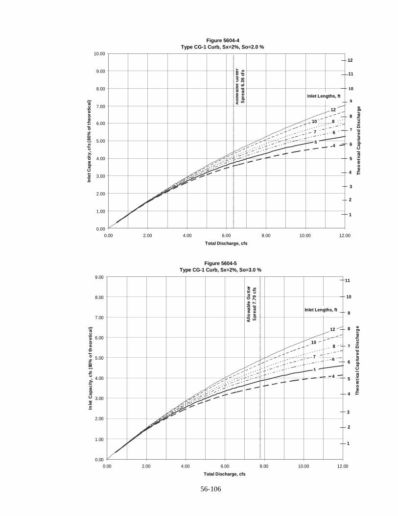
56-106
Figure 5604-4Type CG-1 Curb, Sx=2%, So=2.0 %
0.00
1.00
2.00
3.00
4.00
5.00
6.00
7.00
8.00
9.00
10.00
0.00 2.00 4.00 6.00 8.00 10.00 12.00
Total Discharge, cfs
Inle
tCap
aci
ty,c
fs(8
0%of
theo
retic
al)
12
10 8
7 6
54
Inlet Lengths, ft
Allo
wab
leG
utte
rS
prea
d6.
36cf
s
Theo
reti
calC
aptu
red
Dis
char
ge
5
10
7
12
4
6
8
11
1
2
3
9
Figure 5604-5Type CG-1 Curb, Sx=2%, So=3.0 %
0.00
1.00
2.00
3.00
4.00
5.00
6.00
7.00
8.00
9.00
0.00 2.00 4.00 6.00 8.00 10.00 12.00
Total Discharge, cfs
Inle
tC
apac
ity,c
fs(8
0%o
fth
eore
tical
) 12
108
7 6
54
Inlet Lengths, ft
Allo
wab
leG
utt
erS
prea
d7.
79cf
s
Theo
reti
calC
aptu
red
Dis
char
ge
5
10
7
4
6
8
11
1
2
3
9
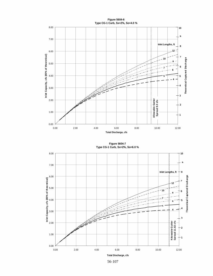
56-107
Figure 5604-6Type CG-1 Curb, Sx=2%, So=4.0 %
0.00
1.00
2.00
3.00
4.00
5.00
6.00
7.00
8.00
0.00 2.00 4.00 6.00 8.00 10.00 12.00
Total Discharge, cfs
Inle
tC
apac
ity,c
fs(8
0%of
theo
retic
al)
12
108
76
54
Inlet Lengths, ft
Allo
wab
leG
utte
rS
prea
d9.
0cf
s
Theo
retic
alC
aptu
red
Dis
char
ge
5
10
7
4
6
8
1
2
3
9
Figure 5604-7Type CG-1 Curb, Sx=2%, So=6.0 %
0.00
1.00
2.00
3.00
4.00
5.00
6.00
7.00
8.00
0.00 2.00 4.00 6.00 8.00 10.00 12.00
Total Discharge, cfs
Inle
tCap
acit
y,cf
s(8
0%of
theo
reti
cal)
12
108
76
54
Inlet Lengths, ftA
llow
able
Gut
ter
Spr
ead
11.0
2cf
s
The
oret
ical
Cap
ture
dD
isch
arge
5
10
7
4
6
8
1
2
3
9
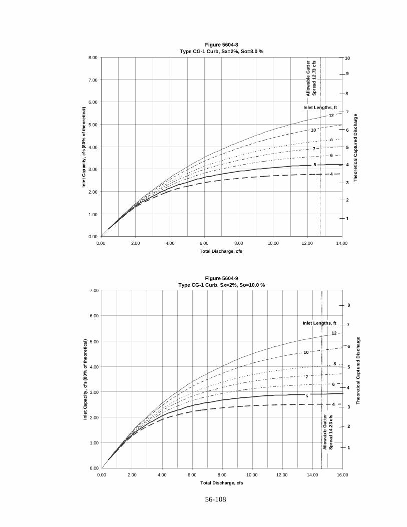
56-108
Figure 5604-8Type CG-1 Curb, Sx=2%, So=8.0 %
0.00
1.00
2.00
3.00
4.00
5.00
6.00
7.00
8.00
0.00 2.00 4.00 6.00 8.00 10.00 12.00 14.00
Total Discharge, cfs
Inle
tCap
acity
,cfs
(80%
ofth
eore
tical
)
12
10
8
76
5
4
Inlet Lengths, ft
Allo
wab
leG
utte
rSp
read
12.7
3cf
s
Theo
retic
alC
aptu
red
Dis
char
ge
5
10
7
4
6
8
1
2
3
9
Figure 5604-9Type CG-1 Curb, Sx=2%, So=10.0 %
0.00
1.00
2.00
3.00
4.00
5.00
6.00
7.00
0.00 2.00 4.00 6.00 8.00 10.00 12.00 14.00 16.00
Total Discharge, cfs
Inle
tCap
acity
,cfs
(80%
ofth
eore
tical
)
10
8
7
6
5
4
Inlet Lengths, ftAl
low
able
Gut
ter
Spre
ad14
.23
cfs
Theo
retic
alC
aptu
red
Dis
char
ge
12
5
7
4
6
8
1
2
3
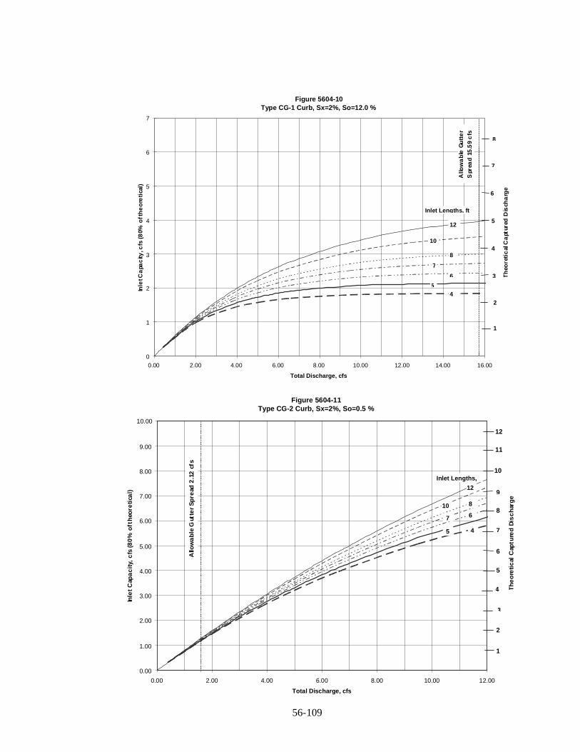
56-109
Figure 5604-11Type CG-2 Curb, Sx=2%, So=0.5 %
0.00
1.00
2.00
3.00
4.00
5.00
6.00
7.00
8.00
9.00
10.00
0.00 2.00 4.00 6.00 8.00 10.00 12.00
Total Discharge, cfs
Inle
tC
apa
cit
y,c
fs(8
0%
oft
heo
reti
cal)
12
10 8
7 6
5 4
Allo
wa
ble
Gut
ter
Sp
read
2.1
2cf
s
Inlet Lengths,
Th
eo
reti
cal
Cap
ture
dD
isc
har
ge
5
10
7
12
4
6
8
11
1
2
3
9
Figure 5604-10Type CG-1 Curb, Sx=2%, So=12.0 %
0
1
2
3
4
5
6
7
0.00 2.00 4.00 6.00 8.00 10.00 12.00 14.00 16.00
Total Discharge, cfs
Inle
tCa
pac
ity,c
fs(8
0%o
fth
eo
reti
cal)
12
10
8
7
6
54
Inlet Lengths, ft
Allo
wa
ble
Gu
tte
rS
prea
d15
.59
cfs
Th
eore
tic
alC
apt
ured
Dis
cha
rge
5
7
4
6
8
1
2
3

56-110
Figure 5604-12Type CG-2 Curb, Sx=2%, So=1.0 %
0.00
1.00
2.00
3.00
4.00
5.00
6.00
7.00
8.00
9.00
0.00 2.00 4.00 6.00 8.00 10.00 12.00
Total Discharge, cfs
Inle
tC
ap
aci
ty,c
fs(8
0%
of
theo
reti
ca
l)
12
10 8
7 6
54
Inlet Lengths, ft
Allo
wab
leG
utt
erS
pre
ad
3cf
s
Th
eo
reti
cal
Ca
ptu
red
Dis
ch
arg
e
5
10
7
4
6
8
11
1
2
3
9
Figure 5604-13Type CG-2 Curb, Sx=2%, So=2.0 %
0.00
1.00
2.00
3.00
4.00
5.00
6.00
7.00
0.00 2.00 4.00 6.00 8.00 10.00 12.00
Total Discharge, cfs
Inle
tC
apa
city
,cfs
(80
%of
the
ore
tic
al) 12
10
8
76
54
Inlet Lengths, ft
Allo
wa
ble
Gu
tte
rS
pre
ad
4.2
4c
fs
Th
eo
reti
cal
Ca
ptu
red
Dis
ch
arg
e
5
7
4
6
8
1
2
3

56-111
Figure 5604-14Type CG-2 Curb, Sx=2%, So=3.0 %
0.00
0.50
1.00
1.50
2.00
2.50
3.00
3.50
4.00
4.50
5.00
5.50
0.00 2.00 4.00 6.00 8.00 10.00 12.00
Total Discharge, cfs
Inle
tC
apa
cit
y,c
fs(8
0%
of
the
ore
tic
al)
12
10
8
7
6
5
4
Inlet Lengths, ft
Allo
wa
ble
Gu
tter
Sp
rea
d5.
20
Th
eo
reti
cal
Ca
ptu
red
Dis
cha
rge
2.5
5
3.5
2
3
4
5.5
0.
1
1.
4.5
6
6.5
Figure 5604-15Type CG-2 Curb, Sx=2%, So=4.0 %
0.00
0.50
1.00
1.50
2.00
2.50
3.00
3.50
4.00
4.50
5.00
0.00 2.00 4.00 6.00 8.00 10.00 12.00
Total Discharge, cfs
Inle
tC
apa
cit
y,c
fs(8
0%
oft
heo
retic
al) 12
10
8
76
5
4
Inlet Lengths, ft
All
ow
ab
leG
utt
er
Sp
rea
d6
cfs
Th
eore
tica
lCa
ptu
red
Dis
ch
arg
e
2.5
5
3.5
2
3
4
5.5
0.5
1
1.5
4.5
6
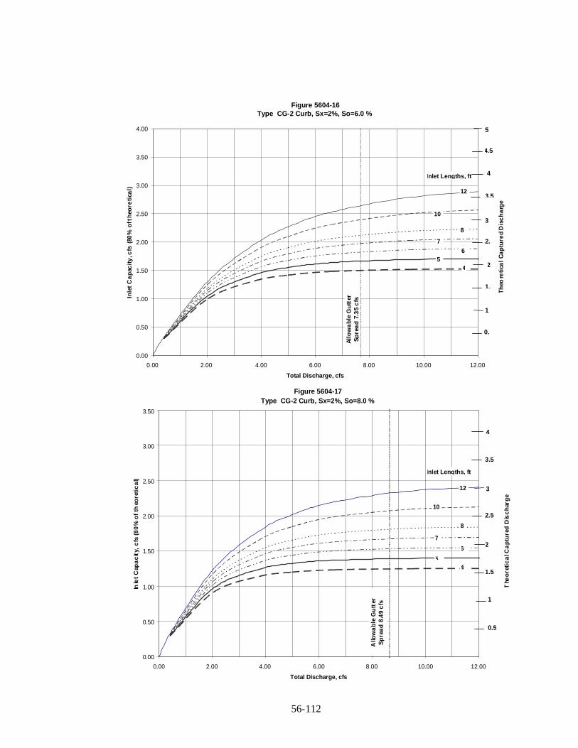
56-112
Figure 5604-16Type CG-2 Curb, Sx=2%, So=6.0 %
0.00
0.50
1.00
1.50
2.00
2.50
3.00
3.50
4.00
0.00 2.00 4.00 6.00 8.00 10.00 12.00
Total Discharge, cfs
Inle
tC
ap
acit
y,c
fs(8
0%
oft
heo
reti
cal) 12
8
7
65
4
10
Inlet Lengths, ft
All
ow
ab
leG
utt
erS
pre
ad
7.3
5c
fs
Th
eore
tica
lC
ap
ture
dD
isc
ha
rge
2.
5
3.5
2
3
4
0.
1
1.
4.5
Figure 5604-17Type CG-2 Curb, Sx=2%, So=8.0 %
0.00
0.50
1.00
1.50
2.00
2.50
3.00
3.50
0.00 2.00 4.00 6.00 8.00 10.00 12.00
Total Discharge, cfs
Inle
tC
apa
cit
y,c
fs(8
0%
of
theo
reti
ca
l)
12
10
8
7
6
54
Inlet Lengths, ft
Allo
wa
ble
Gu
tter
Sp
rea
d8
.49
cfs
The
ore
tic
alC
ap
ture
dD
isc
har
ge
2.5
3.5
2
3
4
0.5
1
1.5
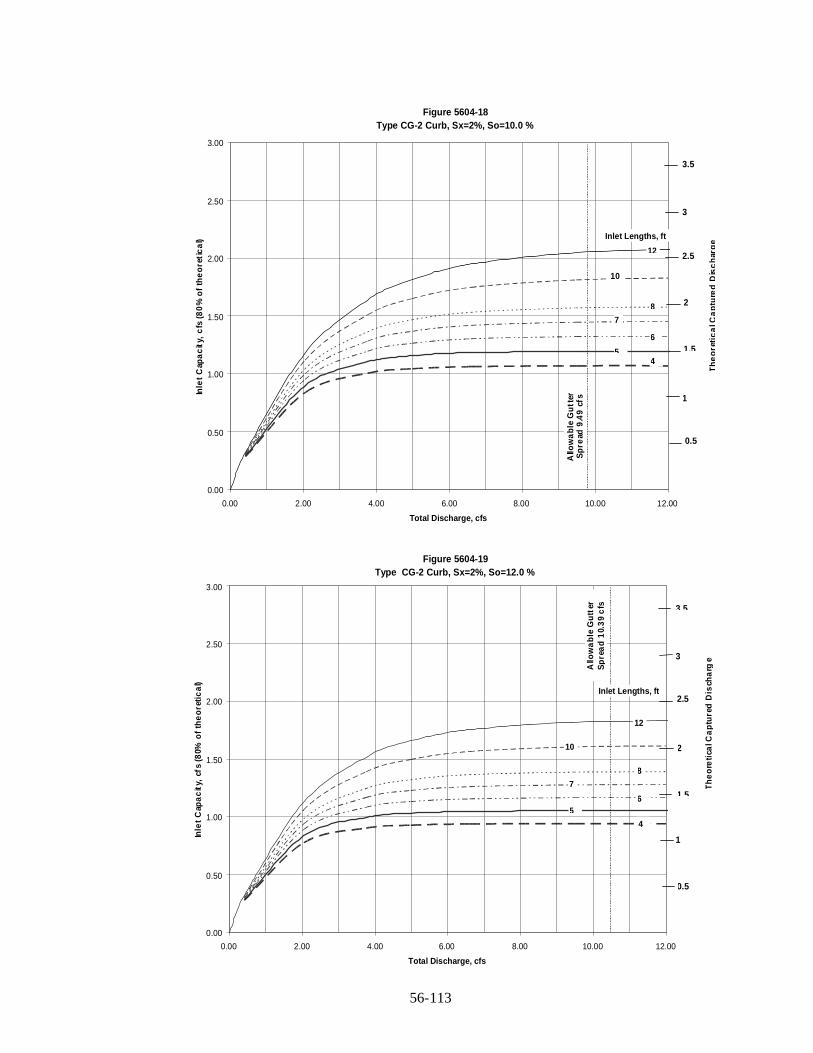
56-113
Figure 5604-18Type CG-2 Curb, Sx=2%, So=10.0 %
0.00
0.50
1.00
1.50
2.00
2.50
3.00
0.00 2.00 4.00 6.00 8.00 10.00 12.00
Total Discharge, cfs
Inle
tC
apa
cit
y,c
fs(8
0%
of
the
ore
tic
al)
12
10
8
7
6
54
Inlet Lengths, ft
Allo
wa
ble
Gu
tter
Sp
read
9.4
9cf
s
Th
eo
reti
ca
lCa
ptu
red
Dis
ch
arg
e
2.5
3.5
2
3
0.5
1
1.5
Figure 5604-19Type CG-2 Curb, Sx=2%, So=12.0 %
0.00
0.50
1.00
1.50
2.00
2.50
3.00
0.00 2.00 4.00 6.00 8.00 10.00 12.00
Total Discharge, cfs
Inle
tC
apa
cit
y,cf
s(8
0%o
fth
eo
reti
ca
l)
12
10
8
7
65
4
Inlet Lengths, ft
Allo
wa
ble
Gu
tter
Sp
rea
d1
0.3
9c
fs
Th
eo
reti
calC
ap
ture
dD
isch
arg
e2.5
3.5
2
3
0.5
1
1.5
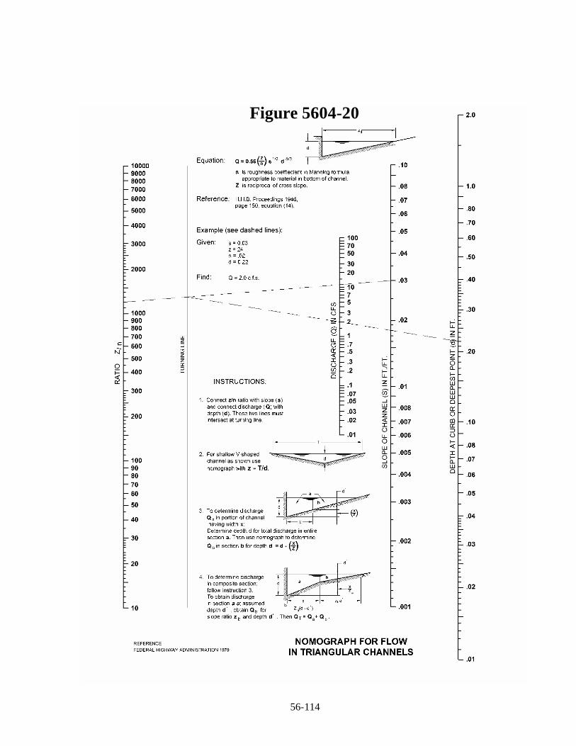
56-114
Figure 5604-20
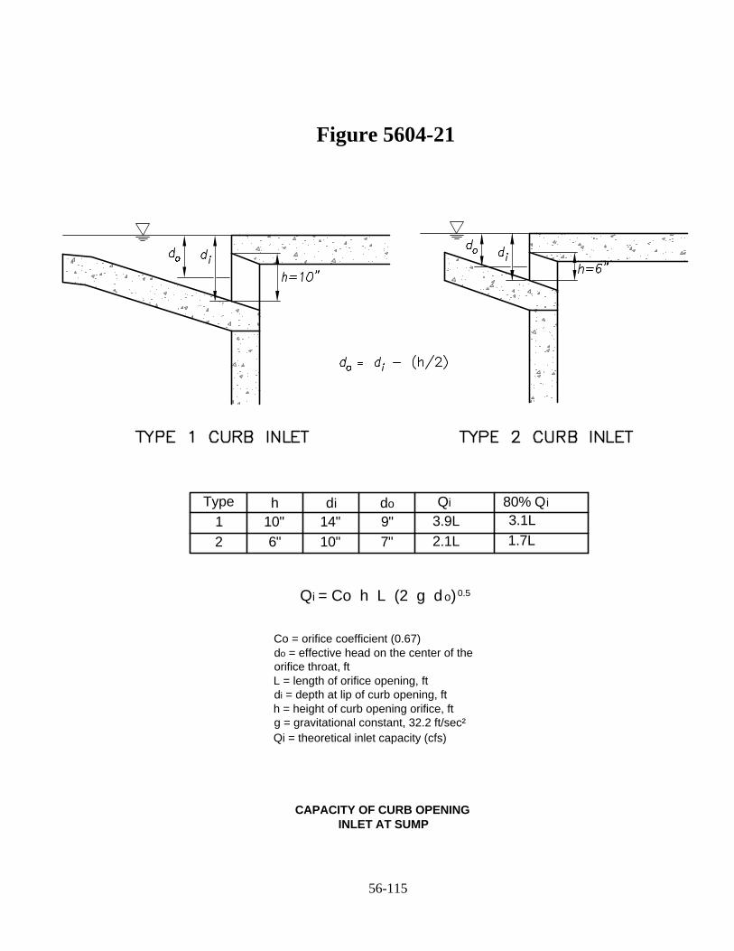
Type h di do Qi 80% Qi
1 10" 14" 9"
2 6" 10" 7"
3.9L
2.1L
3.1L
1.7L
Qi = Co h L (2 g d o)0.5
Figure 5604-21
56-115
Co = orifice coefficient (0.67)
do = effective head on the center of the
orifice throat, ft
L = length of orifice opening, ft
di = depth at lip of curb opening, ft
h = height of curb opening orifice, ft
g = gravitational constant, 32.2 ft/sec²
Qi = theoretical inlet capacity (cfs)
CAPACITY OF CURB OPENING INLET AT SUMP

56-116
Figure 5605-1A: Typical Stream Characteristics A
Low flow channelValley wall
High flow channel
Pool RiffleTree scrolls indicating historicalalignment
Point bar
Thalweg
Figure 5605-1B: Typical Stream Characteristics B
Wavelength
AmplitudeRadius ofCurvature
Channel Length
Thalweg

56-117
Figure 5605-1C: Typical Stream Characteristics C
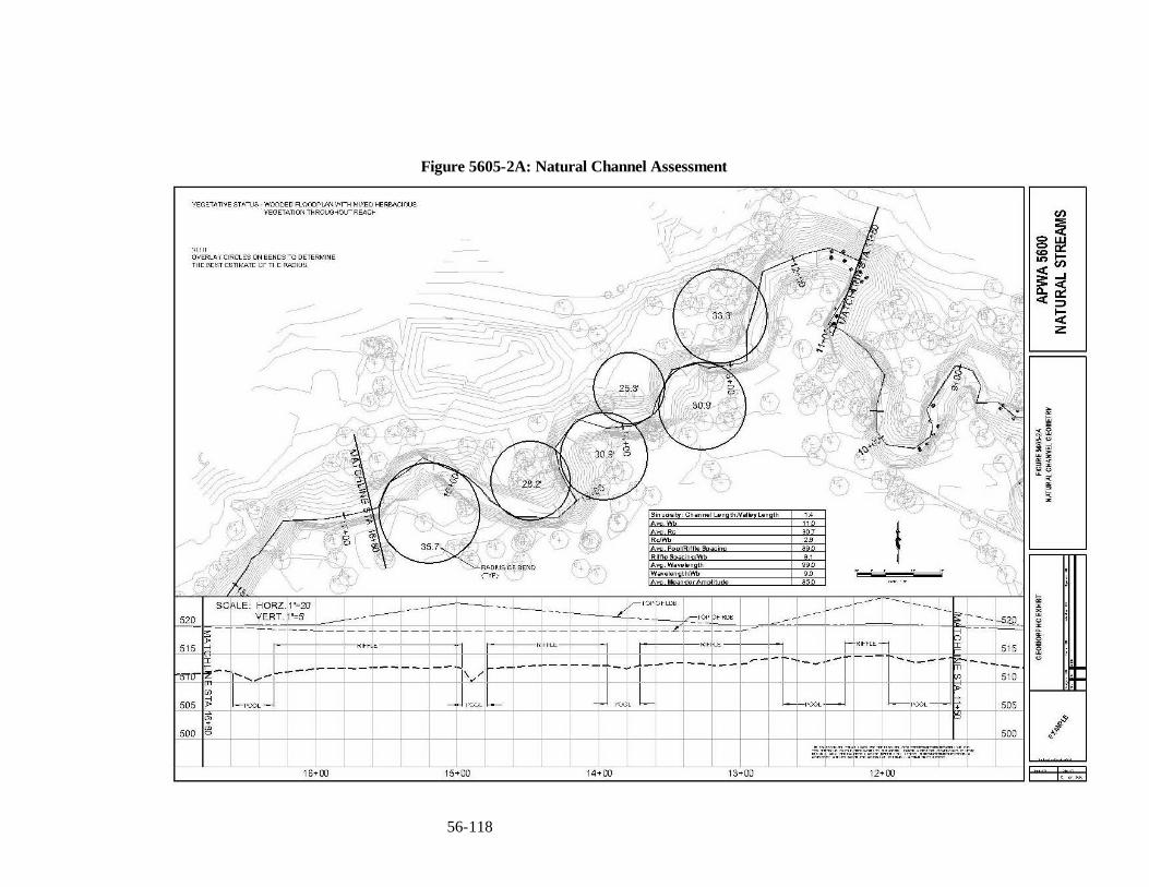
56-118
Figure 5605-2A: Natural Channel Assessment
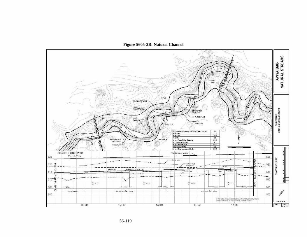
56-119
Figure 5605-2B: Natural Channel

56-120
Figure 5605-3: Grade Control Structure
PROFILE
SECTION THROUGH KEY
K
G+J
SECTION THROUGH RAMP
J
CRESTRAMP
CR
EST
A
TOP OF BANK
F
G
TOP OF BANK
TOP EDGE OF CREST AND EDGE OF KEY TRENCH
FLOW
KEY
NL
H
E
A
TOP OF BANK
TOE OF SLOPE
FLOW
B
A
B C D E F G H I J K L M N
STREAM BANK ANGLE (50° < A < 80°)CREST RADIUS TAIL ANGLE(50° < A < 80°)END OF RAMP RADIUSCREST WIDTHCREST HEIGHTKEY THICKNESSP1.5D90KEY WIDTHP1.5D90
RAMP GRADE 20H:1VRAMP THICKNESSP1.5D100
RAMP LENGTHCREST SIDE SLOPECREST SIDE SLOPEEMBANKMENT KEY
EXISTING GRADE
C
LIMIT OF ROCK
C
J
EXISTINGGRADE
EXISTINGGRADE
N
A
M
I
RAMP
B
KEY
B
D
C
Notes1. The depth of key trench shall be a minimum of 1.5 D90.The crest shall slope downward from the stream bank to the
center of the structure to focus the flow to the channel center. The tail ramp is generally sloped at 20 horizontal to 1vertical and dissipates energy gradually over it length. The upstream face is not perpendicular to the flow but has anupstream oriented “V” or arch shape in plan form.
2. For item A, Stream Bank Angle, and item C Tail Angle, the lower end of the range should be used for softer soils.3. For items L and M, crest angle, the typical range is 5 to 1 to 10 to 1.
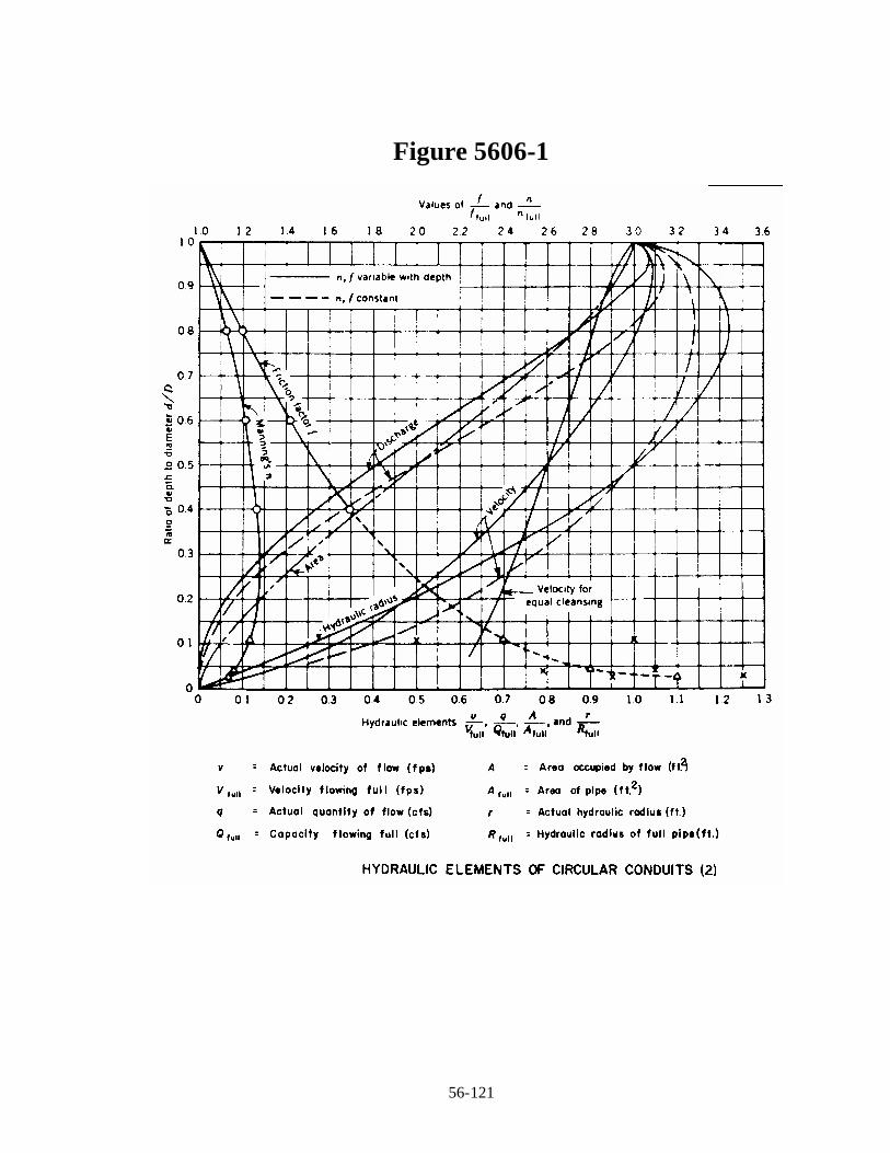
56-121
Figure 5606-1
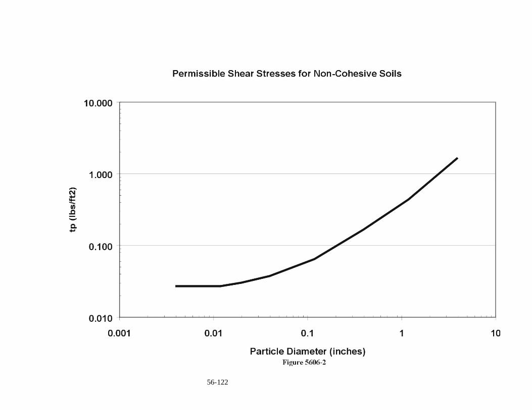
56-122

56-123

56-124
Figure 5608-1

56-125
REFERENCES

56-126
This page intentionally left blank

56-127
Alexander, T.T., and Wilson, G.L., 1995, Technique for Estimating the 2- to 500- YearFlood Discharges on Unregulated Streams in Rural Missouri: U.S. Geological SurveyWater-Resources Investigations Report 95-4231, 33 p.
Becker, L.D., 1986, Techniques for Estimating Flood-Peak Discharges from Urban Basinsin Missouri: U.S Geological Survey Water-Resources Investigations Report 86-4322, 38p.
Castro, J., 1999 Design of Stream Barbs, USDA, NRCS, Engineering Technical Note No.23.
Center for Watershed Protection, Site Planning for Urban Stream Protection”,http://www.cwp.org/SPSP/TOC.htm
Chow, V.T., 1988. Open-Channel Hydraulics, McGraw-Hill Book Publishing Company.
Chow, V.T., 1964. Handbook of Applied Hydrology, McGraw-Hill Book PublishingCompany.
Federal Highway Administration (FHA), 1989. Design of Rip-Rap Revetment. HydraulicEngineering Circular (HEC) No. 11.
Federal Highway Administration (FHA), 1983. Hydraulic Design of Energy Dissipatersfor Culverts and Channels, Hydraulic Engineering Circular (HEC) No. 14.
Federal Highway Administration (FHA), 1996. Urban Drainage Design Manual,Hydraulic Engineering Circular No. 22.
Federal Interagency Stream Restoration Working Group, (Interagency) 1998 withAddenda 2001. Stream Corridor Restoration: Principles, Processes and Practices – StreamCorridor Restoration Handbook.
Gray, D.H. and R.B. Sotir, 1996. Biotechnical and Soil Bioengineering SlopeStabilization, John Wiley and Sons.
Heraty, M., Herson-Jones, L.M. and B. Jordan, 1995, Riparian Buffer Strategies forUrban Watersheds, Metropolitan Washington Council of Governments.
Johnson, P.A., 2002. Incorporating Road Crossings into Stream and River RestorationProjects, Ecological Restoration, Vol.20, No.4.
Johnson, P. A., G. L. Gleason, and R. D. Hey, 1999. Rapid Assessment of ChannelStability in Vicinity of Road Crossings, ASCE, Journal of Hydraulic Engineering, Vol.125, No. 6.

56-128
Lane, E.W., 1955. The Importance of Fluvial Morphology in Hydraulic Engineering,Proceedings of the American Society of Civil Engineers, vol. 81, no. 795, 17p.
Leopold, LB., M.G. Wolman, and I.P. Miller, 1964. Fluvial Processes in Geomorphology,W. H. Freeman and Co.
McEnroe, Bruce M. and Hongying Zhao (2001). Lag Times of Urban and DevelopingWatersheds in Johnson County, Kansas. Report No. K-TRAN: KU-99-5, KansasDepartment of Transportation.
McEnroe, Bruce M. and Gonzalez Pablo (2002). Storm Durations and AntecedentMoisture Conditions for Flood Discharge Estimation, Kansas. Report No. K-TRAN: KU-02-04, Kansas Department of Transportation.
National Academy of Sciences, 1999, Riparian Zones: Function and Strategies forManagement, WSTB –U-98-01-A.
Newbury, R.M., M.Gaboury and C. Watson, 1997. Field Manual of Urban StreamRestoration, Illinois Water Survey. Available from Conservation Technology InformationCenter, IN.
Rasmussen, Patrick P. and Charles A. Perry (2000). Estimation of Peak Streamflows forUnregulated Rural Streams in Kansas. Water-Resources Investigations Report 00-4079,U.S. Geological Survey.
Sauer, V.B., Thomas, W.O., Jr., Stricker, V.A, and Wilson, K.V., 1983, FloodCharacteristcs o Urban Watersheds in the United States: U.S. Geological Survey Water-Supply Paper 2207, 63 p.
Thomas, D.B., S.R. Abt, R.A. Mussetter, and M.D. Harvey, 2000. A Design Procedurefor Step Pool Structures, Procedures Water Resources Engineering and Water ResourcesPlanning and Management, American Society of Civil Engineers.
Urban Water Resources Research Council, 1992. Design and Construction of UrbanStormwater Management Systems, ASCE Manuals and Reports of Engineering PracticeNo. 77, WEF Manual of Practice, FD-20, American Society of Civil Engineers and theWater Environment Federation.
US Army Corps of Engineers, 1989. Sedimentation Investigations of Rivers andReservoirs, US Army Corps of Engineers Engineer Manual EM 1110-2-4000.
US Army Corps of Engineers, 1989. Environmental Engineering for Flood ControlChannels, US Army Corps of Engineers Engineer Manual EM 1110-2-1205.

56-129
US Army Corps of Engineers, 1993. River Hydraulics, US Army Corps of EngineersEngineer Manual EM 1110-2-1416.
US Army Corps of Engineers, 1994. Channel Stability Assessment for Flood ControlProjects, US Army Corps of Engineers Engineer Manual EM 1110-2-1418.
US Army Corps of Engineers, 1994. Hydraulic Design of Flood Control Channels, USArmy Corps of Engineers Engineer Manual EM 1110-2-1601.
US Army Corps of Engineers, 1998, HEC-RAS River Analysis System, HydrologicEngineering Center.
US Army Corps of Engineers, R.R. Copeland, D.N. McComas, C.R. Thorne, P. J. Soar,M.M. Jonas and J.B. Fripp, 2001. Hydraulic Design of Stream Restoration Projects,ERDC/CHL TR-01-28.
US Department of Agriculture. 1999. Design of Streambarbs, Technical Note No. 23.
US Department of Agriculture. Forest Service. C.C. Harrelson, C.L. Rawlins, J.P.Potyondy. Stream Channel Reference Sites: An Illustrated Guide to Field Technique.Rocky Mountain Forest and Range Experiment Station, General Technical Report RM-245. 1994. Available at http://www.stream.fs.fed.us/publications/documentsStream.html.
US Department of Agriculture Soil Conservation Service (NRCS), 1996. Stream bank andShoreline Protection, Chapter 16, US Department of Agriculture Soil ConservationService Engineering Field Handbook.
US Department of the Interior, Bureau of Reclamation, 1974. Design of Small Dams, USGovernment Printing Office.
US Department of the Interior. Bureau of Reclamation. 1978. A Water ResourceTechnical Publication. Engineering Monograph No. 25. Hydraulic Design of StillingBasins and Energy Dissipaters. GPO.
US Soil Conservation Service (SCS). June 1986 Technical Release No. 55 "UrbanHydrology for Small Watersheds", 2nd Edition.
US Soil Conservation Service (SCS). August 1981. Technical Release No. 60, "EarthDams and Reservoirs", as Class "C" structures.
Wegner, S., 1999. A Review of the Scientific Literature on Riparian Buffer Width, Extentand Vegetation, Institute of Ecology, University of Georgia.
WEST Consultants, Inc., 1996. Riprap Design System.

56-130
Williams P.B., Swanson, M.L., 1989. A New Approach to Flood Protection Design andRiparian Management, US Department of Agriculture Forest Service General TechnicalReport PSW-110, pp. 40-45.