section 5 rta techniques - assets.gov.ie
TRANSCRIPT
NATIONAL DIRECTORATE FOR FIRE AND EMERGENCY MANAGEMENT JUNE, 2009 RTA HANDBOOK
83
Section 5 RTA Techniques
5.1 Vehicle stability
Introduction
The Fire Service is considered to be the principal rescue service for Road Traffic Accidents, having a primary role to both save life and render humanitarian services.
The speed and method of releasing casualties trapped in RTAs should always be determined by the nature of the casualties’ injuries. Before beginning any work, however, it is essential that vehicles are stabilised. There are a number of reasons for this.
Modern vehicles are designed to provide passengers with a comfortable ride, regardless of road conditions. Suspension and shock absorber units are central in preventing road vibration being transmitted through the wheels to the vehicles occupants. Stabilisation is aimed at avoiding this potential movement of the vehicles on its suspension system during rescue efforts.
In many instances, bystanders and other emergency services attending may already have entered vehicles prior to the arrival of the fire service. These vehicles must still be stabilised. The following extracts serve to highlight the importance of vehicle stabilisation in the overall context of casualty care at RTAs:
`The presence of spinal injury must be assumed with any sudden acceleration or deceleration accident'. (Reference 1 – see References and further reading).
`With an unstable fracture or dislocation of the spine, displacement of as little
as one millimetre may be enough to compress, pinch or shear the spinal cord. This damage may make the difference between normal function and permanent paralysis, therefore it is imperative that no further motion occurs in an unstable spine...' (Reference 1 – see References and further reading).
`Up to 20% of all spinal cord injuries occur after the initial injury. This
additional damage to the cord is caused by movement of the unstable spine during extrication, treatment or transport.' (Reference 2 – see References and further reading).
Stabilisation should therefore be viewed as the first step in casualty care.
It is increasingly commonplace at RTAs for medical rescuers to perform delicate tasks such as intubation, cannulation and drug administration simultaneous with the fire service’s physical rescue efforts. These tasks become almost impossible if the vehicle continues to move on its suspension system.
Far less movement will take place in a stabilised vehicle that is having its roof cut off, its side
removed etc., than in a vehicle that has not been stabilised. With the design of modern vehicles, roof and/or side removal prior to stabilisation may well result in the floor pan sagging.
To save time, chocks, wedges etc. should be taken directly to the vehicle and put in position to
enable immediate access to the casualty. Stabilisation should achieve four objectives
It should safely immobilise a vehicle resting in a dangerous position. It should result in a solid platform being created for rescuers. It should be simple and easy to remember. It should require very little setting up time. As an example, any typical car resting on
all four wheels should take no longer than forty five seconds to stabilise.
NATIONAL DIRECTORATE FOR FIRE AND EMERGENCY MANAGEMENT JUNE, 2009 RTA HANDBOOK
84
Stabilisation method using step chocks and wedges
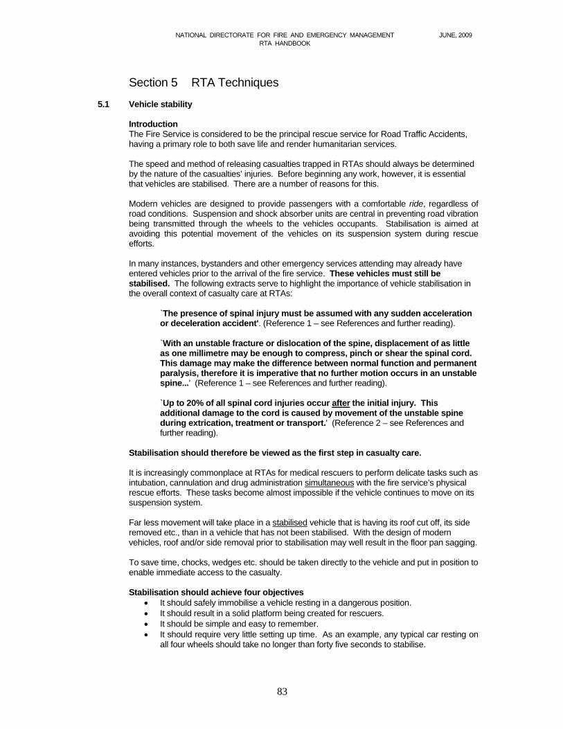
A number of different methods of stabilising vehicles are described below. This should allow for the wide variety of blocks, chocks and wedges carried in each individual fire brigade. Place two step chocks each side of the car - one behind each front wheel, the other in front of each rear wheel to provide stabilisation at all four points. (See Fig 5.1) Tap home a wedge to secure each step chock fast against the vehicles sills.
Figure 5.1 Car chocked for stabilisation The above method can also be used in conjunction with deflated tyres (deflated tyre blocking).
Note: Whilst it may be an effective method of stabilizing vehicles, deflated tyre blocking has two main disadvantages. First, it should be noted that tyre pressures form an important part in Garda Síochána accident investingations into RTAs and, by altering them, this important evidence is lost. Where deflated tyre blocking is used, it is essential that the Garda Síochána are informed. Second, it is often necessary to move a vehicle at some point after the initial collision. If the tyres have been deflated, this becomes more difficult to achieve.
Other situations
Whilst the vast majority of vehicles requiring stabilisation will still be on all four wheels following an RTA, rescuers are sometimes faced with more demanding scenarios, such as vehicles on their roofs, vehicles on their sides, vehicles overhanging substantial drops, etc. Although difficult to provide for every eventuality, the following points may prove to be of value:
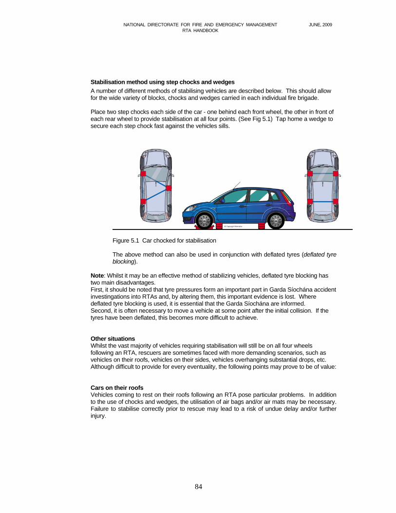
Cars on their roofs Vehicles coming to rest on their roofs following an RTA pose particular problems. In addition
to the use of chocks and wedges, the utilisation of air bags and/or air mats may be necessary. Failure to stabilise correctly prior to rescue may lead to a risk of undue delay and/or further injury.
NATIONAL DIRECTORATE FOR FIRE AND EMERGENCY MANAGEMENT JUNE, 2009 RTA HANDBOOK
85
Figure 5.2 Roof stabilisation
Cars on their sides As a general rule, vehicles found resting on their sides following an RTA should be stabilised
in the position found. The simple placement of blocks and wedges underneath the sides of the vehicle is seldom
sufficient to achieve satisfactory stability, as the vehicle's centre of gravity remains high and movement is still likely during rescue efforts.
Stabilisation for these vehicles should be considered in phases.
Phase 1. Blocks and wedges should be placed underneath the vehicle at both sides. This should take out sufficient movement to allow for early and CAREFUL glass management and entry to the vehicle.
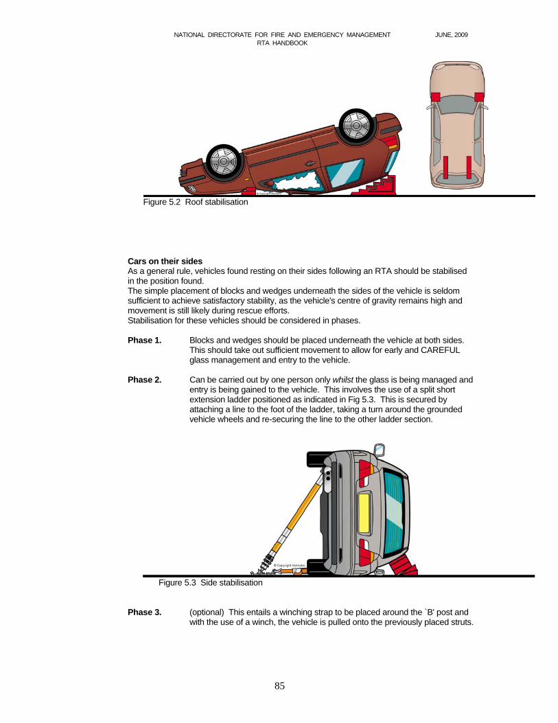
Phase 2. Can be carried out by one person only whilst the glass is being managed and
entry is being gained to the vehicle. This involves the use of a split short extension ladder positioned as indicated in Fig 5.3. This is secured by attaching a line to the foot of the ladder, taking a turn around the grounded vehicle wheels and re-securing the line to the other ladder section.
Figure 5.3 Side stabilisation Phase 3. (optional) This entails a winching strap to be placed around the `B' post and
with the use of a winch, the vehicle is pulled onto the previously placed struts.
NATIONAL DIRECTORATE FOR FIRE AND EMERGENCY MANAGEMENT JUNE, 2009 RTA HANDBOOK
86
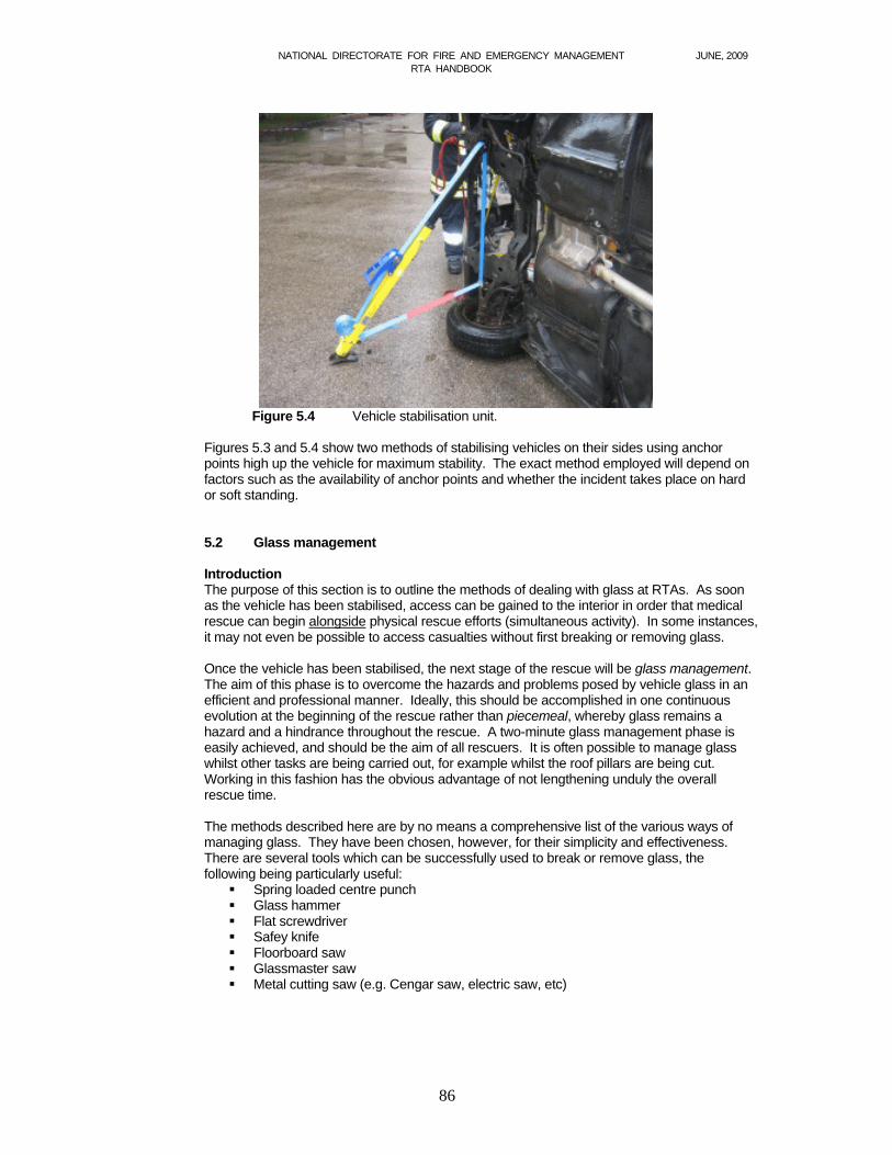
Figure 5.4 Vehicle stabilisation unit.
Figures 5.3 and 5.4 show two methods of stabilising vehicles on their sides using anchor
points high up the vehicle for maximum stability. The exact method employed will depend on factors such as the availability of anchor points and whether the incident takes place on hard or soft standing.
5.2 Glass management
Introduction The purpose of this section is to outline the methods of dealing with glass at RTAs. As soon
as the vehicle has been stabilised, access can be gained to the interior in order that medical rescue can begin alongside physical rescue efforts (simultaneous activity). In some instances, it may not even be possible to access casualties without first breaking or removing glass.
Once the vehicle has been stabilised, the next stage of the rescue will be glass management. The aim of this phase is to overcome the hazards and problems posed by vehicle glass in an efficient and professional manner. Ideally, this should be accomplished in one continuous evolution at the beginning of the rescue rather than piecemeal, whereby glass remains a hazard and a hindrance throughout the rescue. A two-minute glass management phase is easily achieved, and should be the aim of all rescuers. It is often possible to manage glass whilst other tasks are being carried out, for example whilst the roof pillars are being cut. Working in this fashion has the obvious advantage of not lengthening unduly the overall rescue time.
The methods described here are by no means a comprehensive list of the various ways of
managing glass. They have been chosen, however, for their simplicity and effectiveness. There are several tools which can be successfully used to break or remove glass, the following being particularly useful:
Spring loaded centre punch Glass hammer Flat screwdriver Safey knife Floorboard saw Glassmaster saw Metal cutting saw (e.g. Cengar saw, electric saw, etc)
NATIONAL DIRECTORATE FOR FIRE AND EMERGENCY MANAGEMENT JUNE, 2009 RTA HANDBOOK
87
Types of glass There are two main different types of glass found in vehicles – toughened glass and laminated
glass. Each has its own characteristics and poses different problems to rescuers at an RTA
5.2.1 Toughened glass management Due to the properties of toughened glass, it will be necessary to reassure the casualty and
protect from fragments by covering with a suitable blanket or sheet. Clear polythene has the advantage of not tending to hold glass fragments within its fibres. In addition there is no shrouding effect which can be particularly disconcerting for a victim already trapped in a confined space.
Toughened glass can be found in any of the windows in a vehicle, although the modern trend
is to fit it in the side and rear screens. The pressure required to break toughened glass is approximately 10,000 p.s.i. However, by
reducing the contact area to a sharp point, the force required to apply this pressure is considerably reduced. An excellent tool to do this is a spring loaded centre punch. It will shatter toughened glass simply by pressing it against a corner of the glass until the punch spring snaps. Invariably, the glass will shatter into hundreds of pieces, but may remain intact. It can then be removed, together with the rubber seal, to ensure no fragments remain.
Several other tools can achieve a similar result to a spring loaded centre punch. Small glass
hammers are becoming increasingly popular, whilst the sharp point of a Cengar saw blade or the point of a screwdriver, although less reliable, can have the same effect.
Side windows should be wound down to avoid an unnecessary breakage, however, if a door
is to be forced subsequently using a powered tool, winding the window down is not enough, as the glass may shatter uncontrollably under the pressure, sending flying glass in all directions. Windows that are to be forced should be wound down leaving approximately 1 cm exposed. This edge should be quickly covered and broken under control, so that the glass then falls safely down inside the door. Rear screens and quarter lights can be managed either by controlled breakage (having first covered the casualty) or by removing them complete.
Unless the rear screen has been bonded in, removal should take no more than seconds to
achieve. If fitted, first prise out the beading strip using a flat screwdriver. Next, using a safety knife flat to the screen, cut around the corners of the screen about 500mm in each direction. Do the same for the other top corner and the loose rubber seal can then be pulled from around the screen. The glass can then be prised out using a screwdriver.
5.2.2 Laminated Glass Management Laminated glass is significantly different to toughened glass - both in its characteristics and in
the problems it poses to rescuers in a road accident entrapment. It is found fitted in the windscreens of virtually all modern cars as well as in the rear screens of some luxury models. It can be easily identified by examining the screen for markings.
Laminated glass consists of a plastic layer sandwiched between two layers of glass. When
broken, this plastic layer serves to hold the screen together into long sharp pieces.
Laminated glass windscreens in early model cars were fixed using the traditional rubber seal method. Removal is straightforward and is achieved by first removing the metal beading and then by cutting around the rubber seal with a safety knife as described previously.
Increasingly however, laminated windscreens are being bonded into their frames, using a variety of processes - the end result of which is to make the windscreen an integral part of the
roof structure. The obvious problem they present to rescuers is that severing the A, B and C posts is no longer sufficient to remove the roof, as the windscreen retains it in place.
The optimum method of laminated glass removal is cutting.
NATIONAL DIRECTORATE FOR FIRE AND EMERGENCY MANAGEMENT JUNE, 2009 RTA HANDBOOK
88
Various methods can be used to overcome the problems posed by bonded laminated
windscreens, each of which should not delay roof removal as they can be done by one rescuer whilst the roof pillars are being cut.
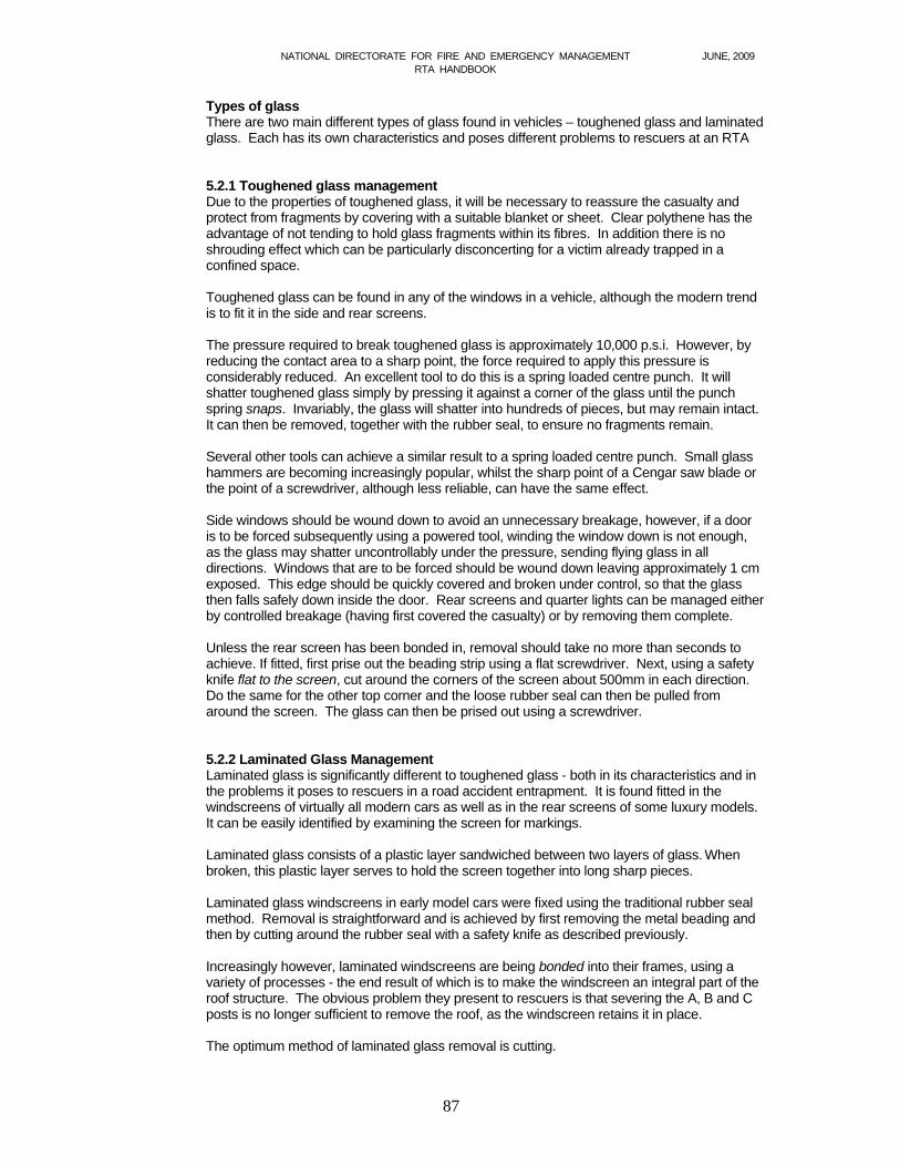
Again, the casualty should be protected from dust inhalation and glass fragments, by covering with a blanket, dust mask, PVC sheet, etc. Then cut one of the A posts low down using either a combi-tool or dedicated cutters. As the remaining pillars are being cut, the windscreen glass can be cut along its width, close to the dashboard - in effect joining the two A post cuts. In this way, the screen is removed with the roof and glass cutting is kept to a minimum. Alternatively, laminated windscreens may be cut simultaneously with the A-posts using a suitable cutter.
Figure 5.5 Use of reciprocating say to remove laminated windscreen
Another method, which overcomes the problem of a bonded laminated windscreen, is to carry out a forward roof flap. Make the normal cuts for a roof removal, and then flap the roof forwards. Frequently, the line of glass breaks completely in two, allowing the roof to be taken clear of the vehicle. If the roof does not flap readily, limited cutting of the laminated glass will remedy the situation.
Tools There are a number of tools capable of cutting through laminated glass in this fashion – for
example, the Glassmaster, which is a hand saw designed specifically for cutting through laminated windscreens. A floorboard saw is also effective at tackling laminated glass.
5.2.3 Summary Glass management procedures could well be summarised as follows:
Controlled: When breakage of glass is necessary, it should be done in a
controlled fashion, using appropriate tools. Avoid; If possible, avoid any unnecessary breakage of glass - by winding
down windows, removing complete panels, etc. Protect: At all times, casualties must be protected from glass fragments.

NATIONAL DIRECTORATE FOR FIRE AND EMERGENCY MANAGEMENT JUNE, 2009 RTA HANDBOOK
89
5.3 Rescue and extrication techniques
Introduction
Upon arrival at an incident, personnel will be confronted with a number of factors that will have to be taken into account before attempting to extricate casualties from vehicles.
The traditional approach to the actual extrication or disentanglement phase of the rescue has always been, you can't pre-plan - they're all different, with what little pre-planning and training that has taken place being largely confined to scene and crew safety. This is an outdated approach that contributes little to the life saving process.
Fundamental to the concepts of aggressive rescue and the team approach to RTA rescues is the principle that the majority of entrapments are of a similar type. Pre-planning for these type of entrapments is essential and should be regarded as the foundations on which all further RTA training can then be based. The appreciation of the need to create space, together with the knowledge of how to do so, is the hallmark of a successful Incident Commander, and a further key to reduced entrapment times.
This section highlights a number of ways to create space, together with a brief explanation of their respective merits. They attempt to give guidance in areas where little guidance previously existed, and although each has been extensively field tested, they should therefore be viewed in the light of the exact circumstances facing rescuers.
At all RTAs the nature of the casualty's condition should determine the nature of the
rescue method employed. Prior to commencing physical rescue activities, it is essential that:- - vehicles have been adequately stabilized, - the glass has been safely managed, and, - hard protection is available for placement between tool and casualty.
5.3.1 Primary roof removal As regards where to start when faced with a difficult entrapment, there has been considerable
debate between the relative merits of roof off or side out approaches. When adopting a casualty-centred approach, the arguments in favour of removing the roof first become difficult to challenge. The advantages are:
It creates the maximum amount of space to work in, in the minimum amount of time,
invariably facilitating full access for the medical assessment of casualties.
It gives unrestricted access to a casualty's airway and allows for in-car intubation should the need arise (impossible with the roof on)
It facilitates the placement of spinal immobilisation devices i.e. cervical collars, KEDs, long spinal boards, etc.
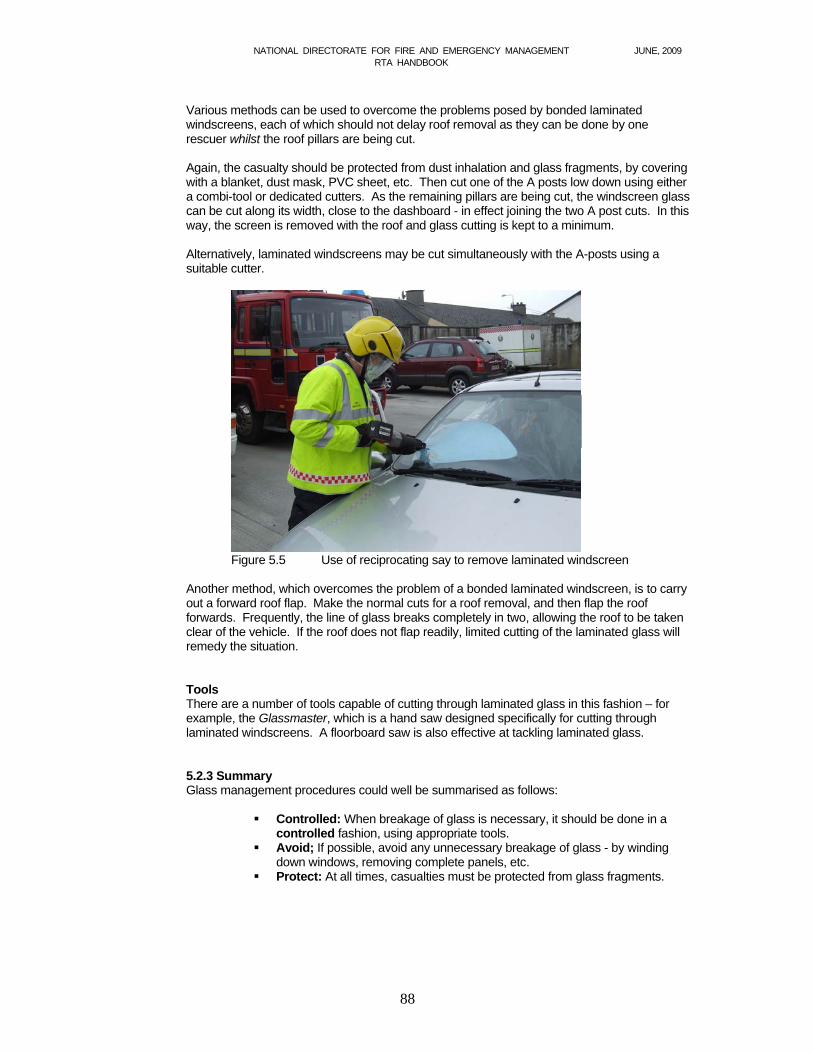
Several points should be borne in mind (see fig 5.6)
All cuts, with the exception of the C posts, should be made as low as possible to reduce the hazard from sharp metal. These should then be covered. (With off-cuts of hose, leather blankets, chimney sheets, etc.) C posts should be cut at their narrowest point.
The last cut should be made nearest to the casualty in order that there is no danger of an unsupported roof dropping and causing injury. It also frees other personnel from having to support it from first cut to last.
Where possible, roofs should be removed totally as opposed to merely flapping them back/forward. One of the main advantages this provides is that it permits the unrestricted use of long spinal boards - an item of equipment increasingly carried by both ambulance and fire service personnel alike.
NATIONAL DIRECTORATE FOR FIRE AND EMERGENCY MANAGEMENT JUNE, 2009 RTA HANDBOOK
90
Figure 5.6 Cutting points when removing a car roof.
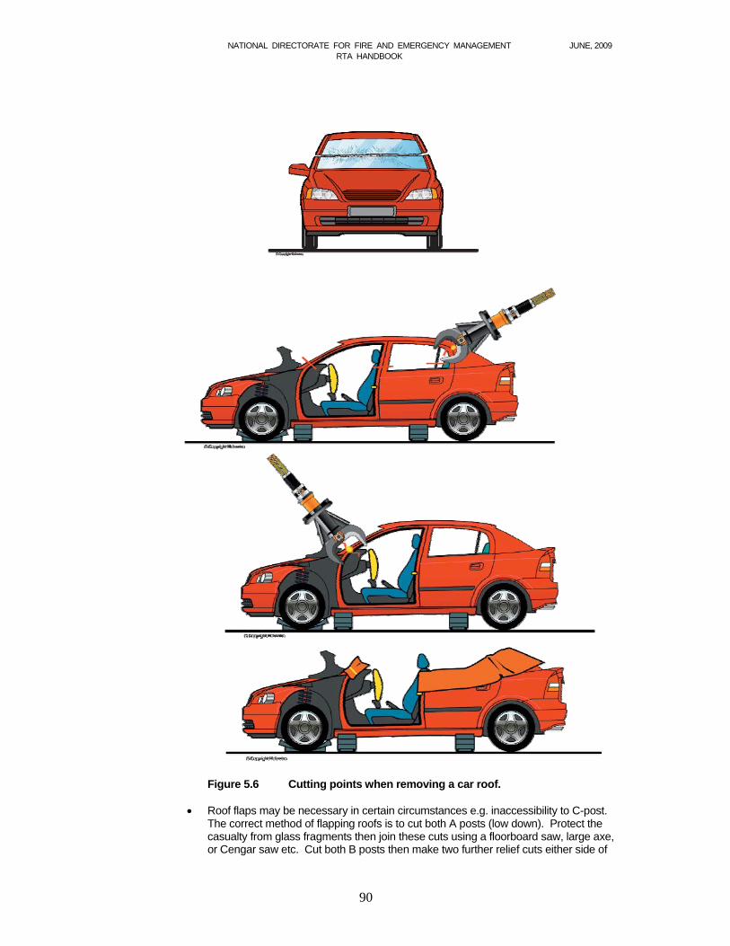
Roof flaps may be necessary in certain circumstances e.g. inaccessibility to C-post.
The correct method of flapping roofs is to cut both A posts (low down). Protect the casualty from glass fragments then join these cuts using a floorboard saw, large axe, or Cengar saw etc. Cut both B posts then make two further relief cuts either side of
NATIONAL DIRECTORATE FOR FIRE AND EMERGENCY MANAGEMENT JUNE, 2009 RTA HANDBOOK
91
the roof, adjacent the C post and flap the roof back. Where difficulty is experienced in bending the roof back, it is often useful to lie a ceiling hook across the roof. Two rescuers can then bear their weight down either end of the hook whilst further rescuers flap the roof over it.
Fig 5.7 Shows a roof flap for car on side or car on four wheels.
Most modern vehicles have bonded, laminated front windscreens with several
different methods being used to bond the glass to the roof structure. This type of windscreen should not add to the time taken in removing a roof. Assuming a driver entrapment, this could be achieved by the following evolution:-
(a) Ensure the casualty is protected from glass fragments. (b) Commence cutting (low) at the casualty's side A pillar (c) Continue in an anti-clockwise direction, finishing with the last cut adjacent the
casualty (casualty's side B post) (d) As soon as the two A posts are cut, the cuts are joined by cutting through the
laminated glass in a straight line along the bottom of the windscreen. This is done whilst the remaining roof pillars are cut, and should not therefore add to the time taken to remove the roof. A variety of tools can be used for this purpose – floorboard saw, large axe, Cengar saw, etc.
Sprung tailgates
On certain older vehicles the tailgates on estate cars have springs to assist the opening operation and when cut can fly up at some considerable speed and force.
This can cause injury to personnel who may be unaware of implications of cutting the tailgate.
A similar problem is encountered on newer vehicles as they have hydraulic or gas struts. With these types of tailgates rescuers should avoid cutting through the struts.
As a general rule, door removals should begin at the front hinge, casualty side. The first problem to overcome is in gaining access to the door hinges as there is often
NATIONAL DIRECTORATE FOR FIRE AND EMERGENCY MANAGEMENT JUNE, 2009 RTA HANDBOOK
92
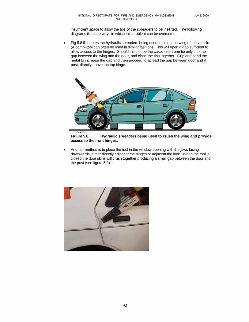
insufficient space to allow the tips of the spreaders to be inserted. The following diagrams illustrate ways in which this problem can be overcome.
Fig 5.8 illustrates the hydraulic spreaders being used to crush the wing of the vehicle.
(A combi-tool can often be used in similar fashion). This will open a gap sufficient to allow access to the hinges. Should this not be the case, insert one tip only into the gap between the wing and the door, and close the tips together. Grip and bend the metal to increase the gap and then proceed to spread the gap between door and A post, directly above the top hinge.
Figure 5.8 Hydraulic spreaders being used to crush the wing and provide
access to the front hinges. Another method is to place the tool in the window opening with the jaws facing
downwards, either directly adjacent the hinges or adjacent the lock. When the tool is closed the door skins will crush together producing a small gap between the door and the post (see figure 5.9).

NATIONAL DIRECTORATE FOR FIRE AND EMERGENCY MANAGEMENT JUNE, 2009 RTA HANDBOOK
93
Figure 5.9 By squeezing the two door skins together access can be gained either to the lock or the hinges.
Another method of gaining access to either the hinges or the lock is to place the spreaders in the door window space, and spread between the top rail and bottom edge of the window opening. It should be pointed out that the top arm of the spreader must be on the outer skin of the door. If the metal on the door starts to split, operations should cease using this method.

NATIONAL DIRECTORATE FOR FIRE AND EMERGENCY MANAGEMENT JUNE, 2009 RTA HANDBOOK
94
Figure 5.10 When using the spreaders between the doors and the posts of the vehicle, it is
advisable after gaining a firm bite with the tips to allow the spreaders to open to their full extent. This often means the operator is able to free the door in one go. When attempting to burst the hinges, the tool should be inserted above the top hinge, encouraging the door to fold down and away from the casualty inside. (see fig 5.11)
Figure 5.11 Correct place to commence spreading operations in order to
break the door hinges.
NATIONAL DIRECTORATE FOR FIRE AND EMERGENCY MANAGEMENT JUNE, 2009 RTA HANDBOOK
95
5.3.2 Side removal
To carry out the complete removal of the sides of four-door vehicles, two methods are recommended. Either a side fold down or a B post rip.
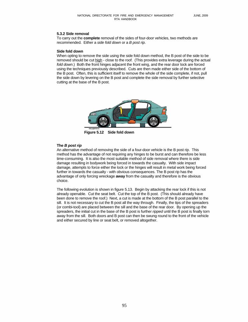
Side fold down
When opting to remove the side using the side fold down method, the B post of the side to be removed should be cut high - close to the roof. (This provides extra leverage during the actual fold down.) Both the front hinges adjacent the front wing, and the rear door lock are forced using the techniques previously described. Cuts are then made either side of the bottom of the B post. Often, this is sufficient itself to remove the whole of the side complete, if not, pull the side down by levering on the B post and complete the side removal by further selective cutting at the base of the B post.
Figure 5.12 Side fold down
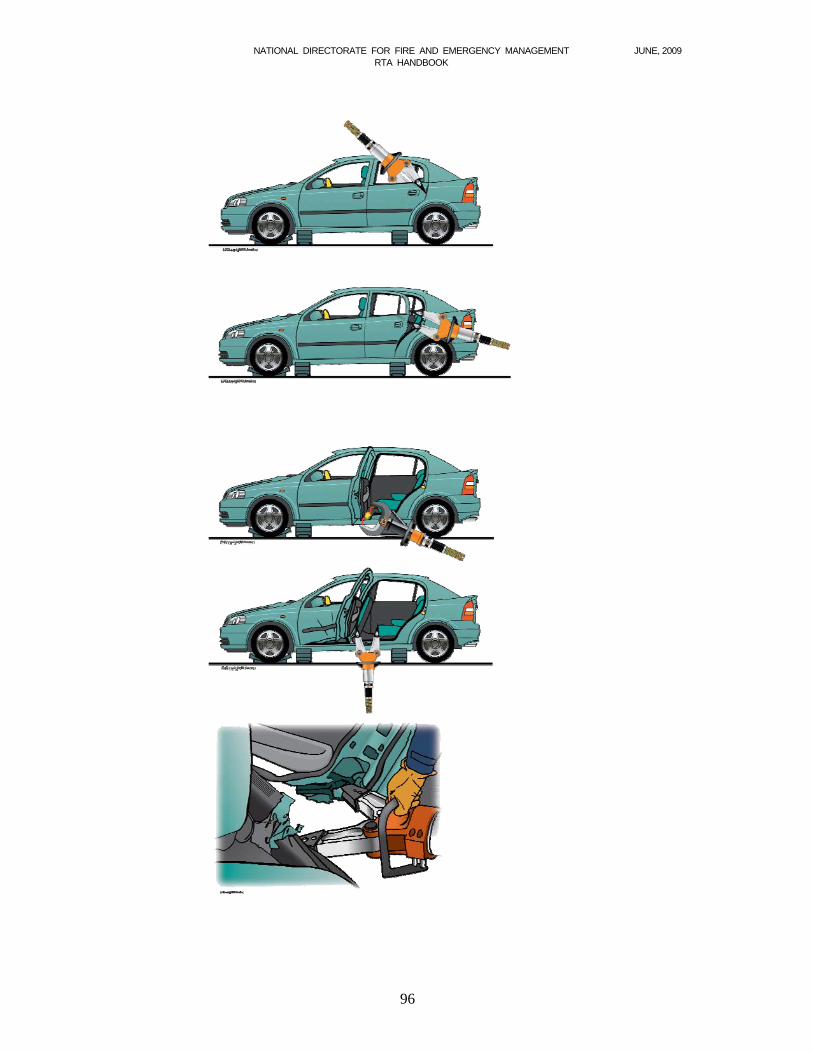
The B post rip An alternative method of removing the side of a four-door vehicle is the B post rip. This
method has the advantage of not requiring any hinges to be burst and can therefore be less time-consuming. It is also the most suitable method of side removal where there is side damage resulting in bodywork being forced in towards the casualty. With side impact damage, attempts to force either the lock or the hinges will result in metal work being forced further in towards the casualty - with obvious consequences. The B post rip has the advantage of only forcing wreckage away from the casualty and therefore is the obvious choice.
The following evolution is shown in figure 5.13. Begin by attacking the rear lock if this is not
already openable. Cut the seat belt. Cut the top of the B post. (This should already have been done to remove the roof.) Next, a cut is made at the bottom of the B post parallel to the sill. It is not necessary to cut the B post all the way through. Finally, the tips of the spreaders (or combi-tool) are placed between the sill and the base of the rear door. By opening up the spreaders, the initial cut in the base of the B post is further ripped until the B post is finally torn away from the sill. Both doors and B post can then be swung round to the front of the vehicle and either secured by line or seat belt, or removed altogether.
NATIONAL DIRECTORATE FOR FIRE AND EMERGENCY MANAGEMENT JUNE, 2009 RTA HANDBOOK
96
NATIONAL DIRECTORATE FOR FIRE AND EMERGENCY MANAGEMENT JUNE, 2009 RTA HANDBOOK
97
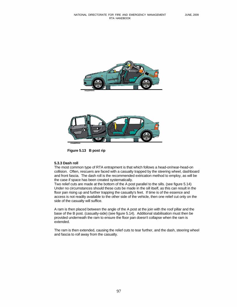
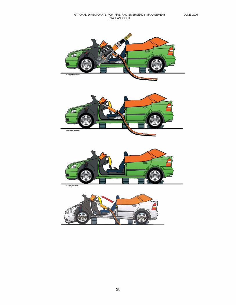
Figure 5.13 B post rip 5.3.3 Dash roll The most common type of RTA entrapment is that which follows a head-on/near-head-on
collision. Often, rescuers are faced with a casualty trapped by the steering wheel, dashboard and front fascia. The dash roll is the recommended extrication method to employ, as will be the case if space has been created systematically.
Two relief cuts are made at the bottom of the A post parallel to the sills. (see figure 5.14) Under no circumstances should these cuts be made in the sill itself, as this can result in the floor pan rising up and further trapping the casualty's feet. If time is of the essence and access is not readily available to the other side of the vehicle, then one relief cut only on the side of the casualty will suffice.
A ram is then placed between the angle of the A post at the join with the roof pillar and the
base of the B post. (casualty-side) (see figure 5.14). Additional stabilisation must then be provided underneath the ram to ensure the floor pan doesn't collapse when the ram is extended.
The ram is then extended, causing the relief cuts to tear further, and the dash, steering wheel
and fascia to roll away from the casualty.
NATIONAL DIRECTORATE FOR FIRE AND EMERGENCY MANAGEMENT JUNE, 2009 RTA HANDBOOK
98
NATIONAL DIRECTORATE FOR FIRE AND EMERGENCY MANAGEMENT JUNE, 2009 RTA HANDBOOK
99
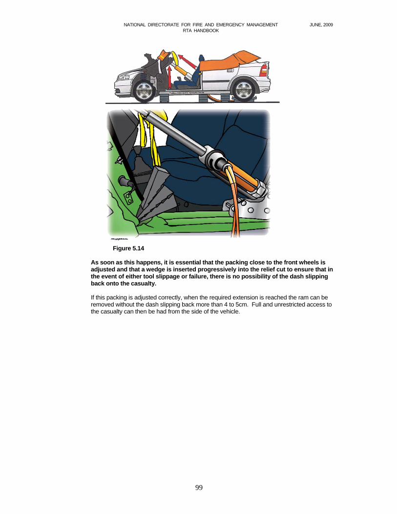
Figure 5.14
As soon as this happens, it is essential that the packing close to the front wheels is
adjusted and that a wedge is inserted progressively into the relief cut to ensure that in the event of either tool slippage or failure, there is no possibility of the dash slipping back onto the casualty.
If this packing is adjusted correctly, when the required extension is reached the ram can be
removed without the dash slipping back more than 4 to 5cm. Full and unrestricted access to the casualty can then be had from the side of the vehicle.

NATIONAL DIRECTORATE FOR FIRE AND EMERGENCY MANAGEMENT JUNE, 2009 RTA HANDBOOK
100
Fig 5.15 This shows a hydraulic ram inserted and extended, resulting in the dash being rolled away from casualty area.
When ramming between the A and B pillars, it will be necessary to provide further blocking under the base of the ram. This is essential otherwise the first movement that will occur when the ram is extended, will be the collapse of the floor pan. In the illustration above, the blocks placed adjacent the rear wheels are also preventing the floor pan from collapsing. When conducting a dash roll on a four-door vehicle, however, it will be necessary to provide further blocking directly below the ram specifically for this purpose. This is normally near to the centre pillar.
At section 1, it was emphasised that the nature of the rescue adopted should be determined by the nature of the casualty's injuries. As an example of that, rescuers may well be faced with a driver trapped by the dashboard whose medical condition is such that they must be removed in minutes if they are to survive. It is clear in this situation that the casualty's condition doesn't allow sufficient time to remove the roof and side prior to carrying out a dash roll. In order to tailor a rescue to suit the situation, the following would be appropriate:
Cut both A posts (high) Cover the casualty and saw through the bonded windscreen (if fitted), joining these
two cuts. Make one relief cut at the base of the driver's A post. (It is not necessary to remove
the door, merely to open it.) Ram between the base of the B post and the angle of the A post at bonnet level. Extricate the casualty, using the rapid extrication technique.
NATIONAL DIRECTORATE FOR FIRE AND EMERGENCY MANAGEMENT JUNE, 2009 RTA HANDBOOK
101
5.4 Winching techniques It may be necessary to move heavy vehicles, rolling stock or cars at various types of vehicle rescue incident – to assist in gaining access to carry out a rescue, or simply to recover a vehicle from a ditch. Many fire and rescue services carry equipment on their appliances to carry out such operations in the form of Tirfor winches, vehicle winches and pulley blocks (sometimes called snatch blocks). It is essential to be able to understand and demonstrate the basic principles of winching. The equipment carried is capable of use in more applications than may be immediately apparent. 5.4.1 Levers The simplest machine of all is the lever which enables us to change mechanical energy involving a small force into mechanical energy involving a large force. For example, a tyre lever enables the exertion of a greater force than that capable of with the fingers. Mechanical Advantage (MA) when using levers can be explained by use of diagrams.
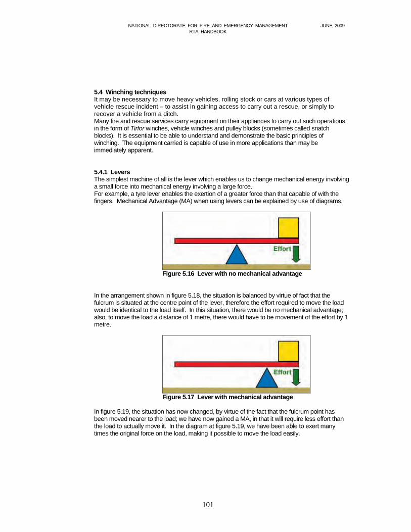
Figure 5.16 Lever with no mechanical advantage
In the arrangement shown in figure 5.18, the situation is balanced by virtue of fact that the fulcrum is situated at the centre point of the lever, therefore the effort required to move the load would be identical to the load itself. In this situation, there would be no mechanical advantage; also, to move the load a distance of 1 metre, there would have to be movement of the effort by 1 metre.
Figure 5.17 Lever with mechanical advantage
In figure 5.19, the situation has now changed, by virtue of the fact that the fulcrum point has been moved nearer to the load; we have now gained a MA, in that it will require less effort than the load to actually move it. In the diagram at figure 5.19, we have been able to exert many times the original force on the load, making it possible to move the load easily.

NATIONAL DIRECTORATE FOR FIRE AND EMERGENCY MANAGEMENT JUNE, 2009 RTA HANDBOOK
102
5.4.2 Change of direction
Figure 5.18 Change of direction
The arrangement shown in figure 5.18 is used when no MA is needed – for example, when the equipment being used at a particular incident is capable of performing the task without any MA, the only problem being that a straight pull cannot be achieved with the winch because of some obstruction. By using a pulley block attached to fixed anchor point, a change of direction of pull can be achieved. 5.4.3 Loads on anchors When the equipment is used for change of direction, a problem to contend with is the load acting on the anchor point to which the pulley block is fixed – as the angle of the pull decreases, so the load on the anchor point increases.
Angle (degrees) Pull 0 2 x P 30 1.97 x P 60 1.73 x P 90 1.41 x P 120 1 x P
Figure 5.19
5.4.4 Mechanical advantage Sometimes, though, weights to be moved are beyond the capabilities of fixed or portable winches – in which case, a MA must be gained if the load is to be moved. To gain MA when using block and tackle, we must have a moving pulley block; we can then determine the MA by the number of falls from the moving block, as shown in the following diagrams.
Figure 5.20 2:1 advantage
The MA is calculated by the number of falls from the moving block. In the diagram at figure 5.20 there are only two, giving a MA of 2:1.
NATIONAL DIRECTORATE FOR FIRE AND EMERGENCY MANAGEMENT JUNE, 2009 RTA HANDBOOK
103
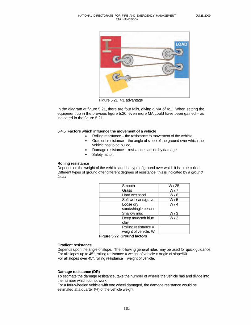
Figure 5.21 4:1 advantage
In the diagram at figure 5.21, there are four falls, giving a MA of 4:1. When setting the equipment up in the previous figure 5.20, even more MA could have been gained – as indicated in the figure 5.21. 5.4.5 Factors which influence the movement of a vehicle
Rolling resistance – the resistance to movement of the vehicle, Gradient resistance – the angle of slope of the ground over which the
vehicle has to be pulled, Damage resistance – resistance caused by damage, Safety factor.
Rolling resistance Depends on the weight of the vehicle and the type of ground over which it is to be pulled. Different types of ground offer different degrees of resistance; this is indicated by a ground factor.
Smooth W / 25 Grass W / 7 Hard wet sand W / 6 Soft wet sand/gravel W / 5 Loose dry sand/shingle beach
W / 4
Shallow mud W / 3 Deep mud/soft blue clay
W / 2
Rolling resistance = weight of vehicle, W
Figure 5.22 Ground factors
Gradient resistance Depends upon the angle of slope. The following general rules may be used for quick guidance. For all slopes up to 45°, rolling resistance = weight of vehicle x Angle of slope/60 For all slopes over 45°, rolling resistance = weight of vehicle. Damage resistance (DR) To estimate the damage resistance, take the number of wheels the vehicle has and divide into the number which do not work. For a four-wheeled vehicle with one wheel damaged, the damage resistance would be estimated at a quarter (¼) of the vehicle weight.
NATIONAL DIRECTORATE FOR FIRE AND EMERGENCY MANAGEMENT JUNE, 2009 RTA HANDBOOK
104
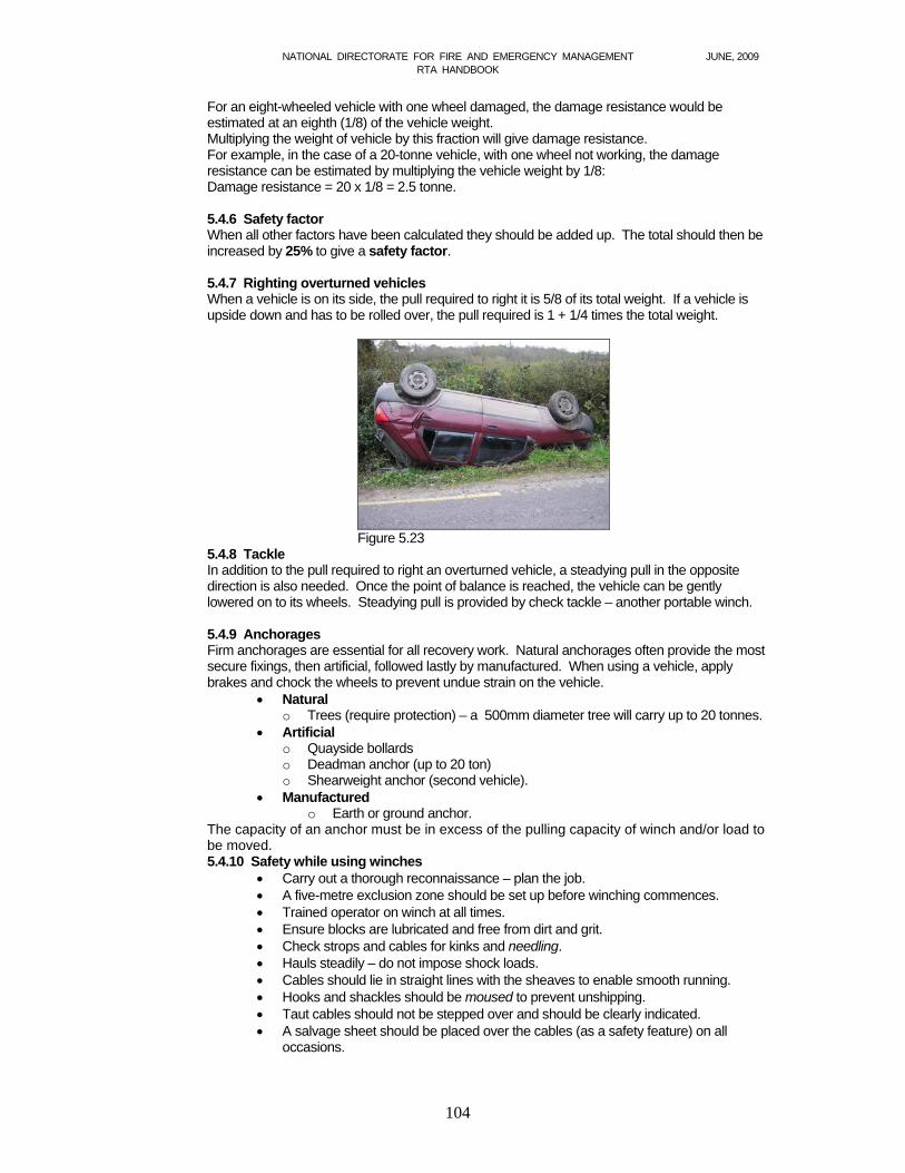
For an eight-wheeled vehicle with one wheel damaged, the damage resistance would be estimated at an eighth (1/8) of the vehicle weight. Multiplying the weight of vehicle by this fraction will give damage resistance. For example, in the case of a 20-tonne vehicle, with one wheel not working, the damage resistance can be estimated by multiplying the vehicle weight by 1/8: Damage resistance = 20 x 1/8 = 2.5 tonne. 5.4.6 Safety factor When all other factors have been calculated they should be added up. The total should then be increased by 25% to give a safety factor. 5.4.7 Righting overturned vehicles When a vehicle is on its side, the pull required to right it is 5/8 of its total weight. If a vehicle is upside down and has to be rolled over, the pull required is 1 + 1/4 times the total weight.
Figure 5.23
5.4.8 Tackle In addition to the pull required to right an overturned vehicle, a steadying pull in the opposite direction is also needed. Once the point of balance is reached, the vehicle can be gently lowered on to its wheels. Steadying pull is provided by check tackle – another portable winch. 5.4.9 Anchorages Firm anchorages are essential for all recovery work. Natural anchorages often provide the most secure fixings, then artificial, followed lastly by manufactured. When using a vehicle, apply brakes and chock the wheels to prevent undue strain on the vehicle.
Natural o Trees (require protection) – a 500mm diameter tree will carry up to 20 tonnes.
Artificial o Quayside bollards o Deadman anchor (up to 20 ton) o Shearweight anchor (second vehicle).
Manufactured o Earth or ground anchor.
The capacity of an anchor must be in excess of the pulling capacity of winch and/or load to be moved. 5.4.10 Safety while using winches
Carry out a thorough reconnaissance – plan the job. A five-metre exclusion zone should be set up before winching commences. Trained operator on winch at all times. Ensure blocks are lubricated and free from dirt and grit. Check strops and cables for kinks and needling. Hauls steadily – do not impose shock loads. Cables should lie in straight lines with the sheaves to enable smooth running. Hooks and shackles should be moused to prevent unshipping. Taut cables should not be stepped over and should be clearly indicated. A salvage sheet should be placed over the cables (as a safety feature) on all
occasions.