section 5 commercial refrigeration unit 22 …
TRANSCRIPT

SECTION 5
COMMERCIAL REFRIGERATION
UNIT 22
CONDENSERS

UNIT OBJECTIVES After studying this unit, the reader should be
able to
• explain the purpose of the condenser in a refrigeration system.
• describe differences between the operating characteristics of water-cooled and air-
cooled systems.
• describe the basis of the heat exchange in a condenser.
• explain the difference between a tube-within-a-tube coil-type condenser and a
tube-within-a-tube serviceable condenser.
• describe the difference between a shell-and-coil condenser and a shell-and-tube
condenser.
• values.
UNIT OBJECTIVES After studying this unit, the reader should be
able to
• describe a wastewater system.
• describe a recirculated water system.
• describe a cooling tower.
• explain the relationship between the condensing refrigerant and the condensing
medium for cooling tower systems.
• compare an air-cooled, high-efficiency condenser with a standard condenser.
• describe the operation of head pressure control values.

THE CONDENSER • Heat exchange surface that rejects system heat
• Rejects sensible heat
– Desuperheating vapor refrigerant from the compressor
– Subcools refrigerant at the outlet of the condenser
• Rejects latent heat during the condensing process
• The greatest amount of heat is transferred during the change of state
• Condenser is on the high pressure side of the system

WATER-COOLED CONDENSERS • More efficient than air-cooled condensers
• Water temperature can be maintained
• Water temperature directly affects system pressures
• Three types of water-cooled condensers
– Tube within a tube condenser
– Shell and coil condenser
– Shell and tube condenser

TUBE WITHIN A TUBE CONDENSER
• Heat exchange takes place between the fluids in the inner and outer
tubes
• Refrigerant flows in the outer tube
• Water flows in the inner tube
• Refrigerant and water flow in opposite directions to maximize the heat
transfer rate
• Depending on the construction, the condenser can be cleaned
mechanically or chemically
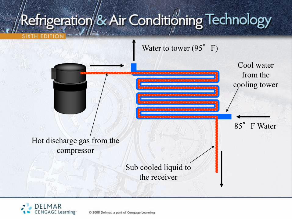
Hot discharge gas from the
compressor
Sub cooled liquid to
the receiver
Cool water
from the
cooling tower
85°F Water
Water to tower (95°F)
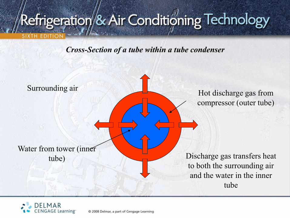
Cross-Section of a tube within a tube condenser
Surrounding air Hot discharge gas from
compressor (outer tube)
Water from tower (inner
tube) Discharge gas transfers heat
to both the surrounding air
and the water in the inner
tube
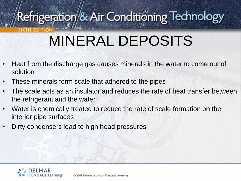
MINERAL DEPOSITS
• Heat from the discharge gas causes minerals in the water to come out of
solution
• These minerals form scale that adhered to the pipes
• The scale acts as an insulator and reduces the rate of heat transfer between
the refrigerant and the water
• Water is chemically treated to reduce the rate of scale formation on the
interior pipe surfaces
• Dirty condensers lead to high head pressures

Cross-Section of a tube within a tube condenser
Surrounding air
Hot discharge gas from
compressor (outer tube)
Water from tower (inner
tube)
Heat transfer between the
refrigerant and the water is
reduced because of the
insulating effect of the
mineral deposits
MINERAL DEPOSITS
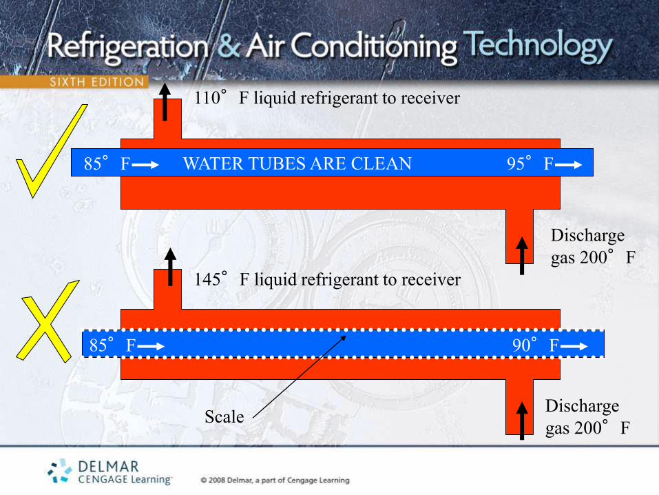
WATER TUBES ARE CLEAN 85°F 95°F
Scale
85°F 90°F
Discharge
gas 200°F
Discharge
gas 200°F
110°F liquid refrigerant to receiver
145°F liquid refrigerant to receiver
MECHANICALLY CLEANABLE
CONDENSERS • Tube within a tube condenser has end flanges
• Flanges are removed to access the water circuit
• The refrigerant circuit remains sealed while the water circuit is open
• The mechanically cleanable tube-in-tube condenser is more costly than
the chemically cleanable version of the condenser

MECHANICALLY CLEANABLE TUBE
WITHIN A TUBE CONDENSER
Water and refrigerant
connections

MECHANICALLY CLEANABLE TUBE WITHIN A
TUBE CONDENSER
Gasket Flange
Access to interior of
water tubes
SHELL AND COIL CONDENSERS
• Coil of tubing enclosed in a welded shell
• Water flows through the coil
• Refrigerant from the compressor is discharged into the shell
• The shell also acts as the receiver
• When refrigerant comes in contact with the cool coil, it condenses and falls to the bottom
• This condenser must be cleaned chemically
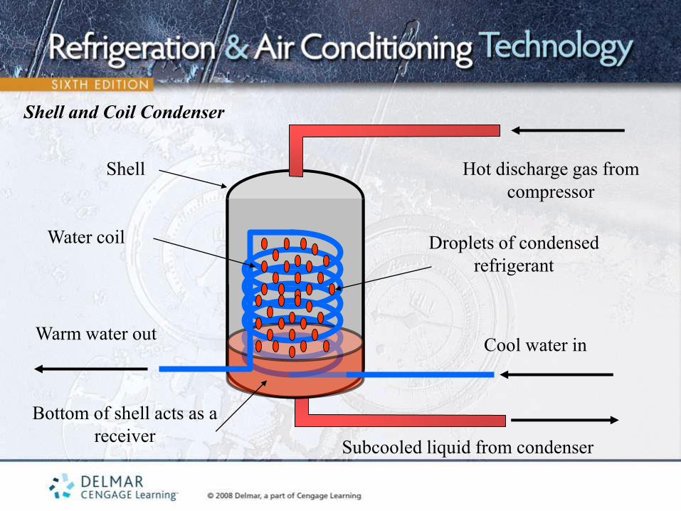
Shell and Coil Condenser
Shell Hot discharge gas from
compressor
Subcooled liquid from condenser
Cool water in Warm water out
Water coil Droplets of condensed
refrigerant
Bottom of shell acts as a
receiver
SHEL AND TUBE
CONDENSERS • Can be cleaned mechanically
• Compressor discharge gas is piped into the shell
• Water flows through the tubes in the condenser
• The ends of the shell are removed for cleaning
• The shell acts as a receiver
• Refrigerant circuit is not disturbed when the ends of the shell (water boxes)
are opened
• Most expensive type of condenser
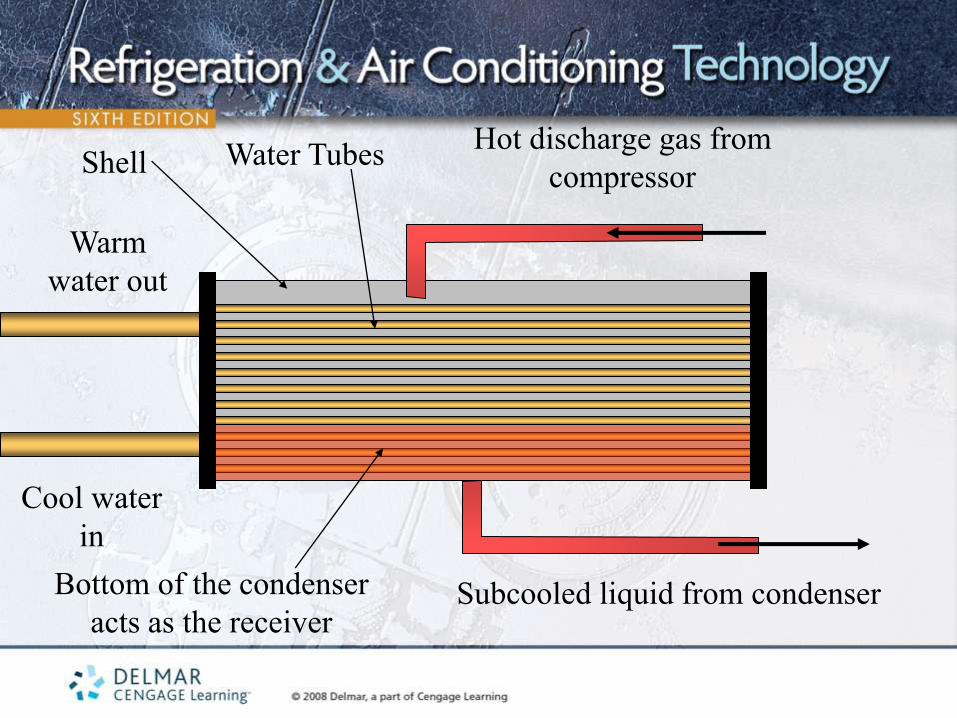
Hot discharge gas from
compressor
Subcooled liquid from condenser
Cool water
in
Warm
water out
Water Tubes
Bottom of the condenser
acts as the receiver
Shell
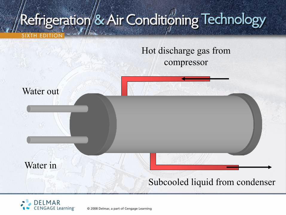
Hot discharge gas from
compressor
Subcooled liquid from condenser
Water in
Water out
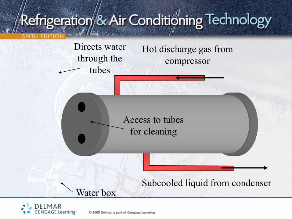
Hot discharge gas from
compressor
Subcooled liquid from condenser Water box
Directs water
through the
tubes
Access to tubes
for cleaning

WASTEWATER SYSTEMS
• Water used once and then “wasted” down the drain
• Economical if water is free or if the system is small
• The main drawback is that the water temperature can vary a great deal
• Typical water temperature is about 75°F
• 75°F wastewater requires a flow of about 1.5 gpm per ton of refrigeration to absorb the heat rejected by the condenser
• Water typically leaves the condenser at 95°F
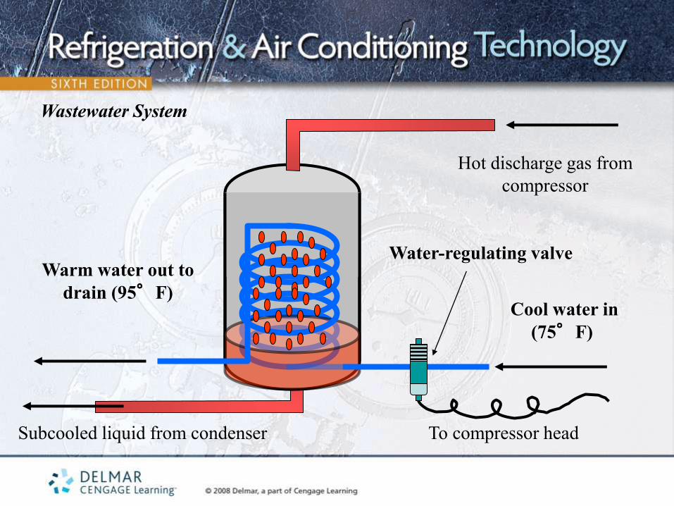
Wastewater System
Hot discharge gas from
compressor
Subcooled liquid from condenser
Cool water in
(75°F)
Warm water out to
drain (95°F)
Water-regulating valve
To compressor head

REFRIGERANT-TO-WATER TEMPERATURE
RELATIONSHIP FOR WASTEWATER
SYSTEMS • Water flow is controlled by a water regulating valve
• Two pressures control the water regulating valve
– The head pressure pushes to open the valve
– The spring pressure pushes to close the valve
• The valve opens when the head pressure rises
• Water temperature is higher in the warmer months
• Water temperature is lower in the cooler months
RECIRCULATED WATER SYSTEMS • The water flowing through the condenser is pumped to a remote location,
cooled and reused
• Design water temperature is 85°F
• A water flow rate of 3.0 gpm per ton of refrigeration is required to absorb
the heat rejected by the system condenser
• The water leaving the condenser is about 95°F
• There is a 10 degree split across the water circuit

Recirculated Water System
Hot discharge gas from
compressor
Subcooled liquid from condenser
Cool water in
(85°F)
Warm water out to
drain (95°F)
COOLING TOWERS • Device used to remove heat from the water used in recirculated water
systems
• Towers can cool the water to a temperature within 7°F of the wet bulb
temperature of the air surrounding the tower
• If the wet bulb temperature is 90 degrees, water can be cooled to a
temperature as low as 83°F
• Natural draft, forced draft, or evaporative

Cooled water out (85°F)
Hot water in (95°F)
Air in 95°F dry
bulb, 78°F wet
bulb
Air out
Fan motor

NATURAL DRAFT COOLING TOWERS
• Redwood, fiberglass or galvanized sheet metal
• There are no blowers to move air through the tower
• Natural breezes move air through the tower
• Water enters the tower from the top and is cooled as the water falls to the
bottom
• Some water evaporates in the process, helping to cool the remaining water
in the tower
• Additional water is added through a float valve

FORCED OR INDUCED DRAFT TOWERS
• Use a fan or blower to move air through the tower
• As the water falls through the tower, air is moved across it to aid in the
cooling process
• Can be located almost anywhere
• The fan is cycled on and off to maintain the desired water temperature
• Forced draft – Air is pushed through the tower
• Induced draft – Air is pulled through the tower
EVAPORATIVE CONDENSERS
• Designed to operate full of liquid
• A latent heat transfer takes place throughout the coil
• Coil efficiency is maximized
• Other devices must be used to prevent liquid from entering the compressor
• Normally use a float-type metering device to keep the liquid level in the coil
high

AIR-COOLED CONDENSERS
• Uses air to absorb heat rejected by the system
• Used in locations where water is difficult to use
• Horizontal, vertical, or side intake and top discharge
• Hot gas enters the condenser from the top
• For standard efficiency systems, the refrigerant will condense at a
temperature about 30°F higher than the outside ambient temperature
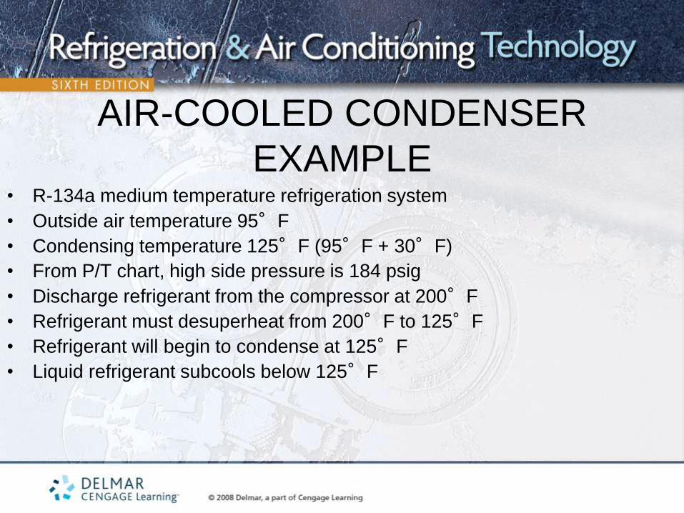
AIR-COOLED CONDENSER
EXAMPLE • R-134a medium temperature refrigeration system
• Outside air temperature 95°F
• Condensing temperature 125°F (95°F + 30°F)
• From P/T chart, high side pressure is 184 psig
• Discharge refrigerant from the compressor at 200°F
• Refrigerant must desuperheat from 200°F to 125°F
• Refrigerant will begin to condense at 125°F
• Liquid refrigerant subcools below 125°F
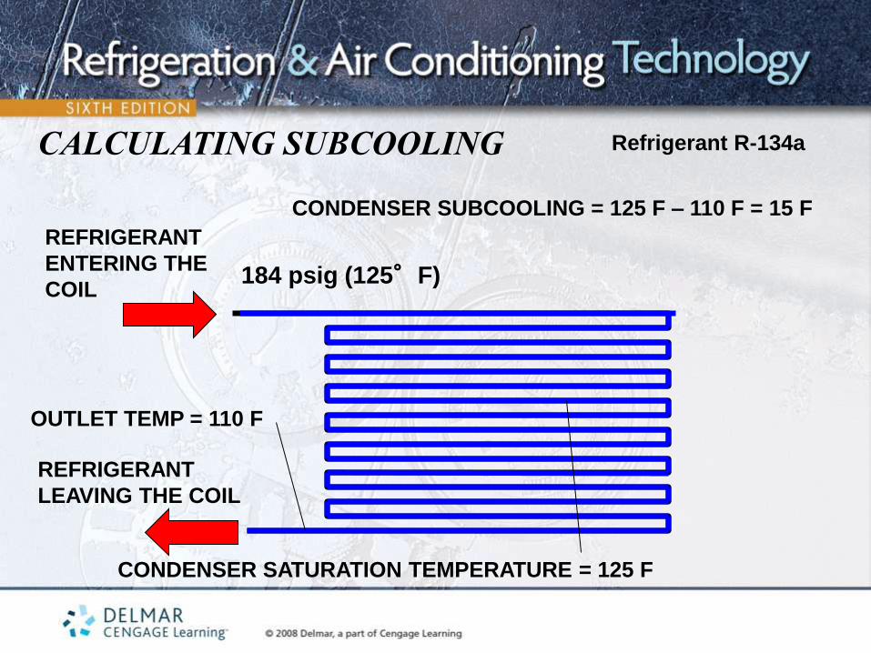
REFRIGERANT
ENTERING THE
COIL
REFRIGERANT
LEAVING THE COIL
Refrigerant R-134a
CONDENSER SATURATION TEMPERATURE = 125 F
OUTLET TEMP = 110 F
CONDENSER SUBCOOLING = 125 F – 110 F = 15 F
CALCULATING SUBCOOLING
184 psig (125°F)

HIGH-EFFICIENCY
CONDENSERS • Have larger surface areas than standard condensers
• Allow systems to operate at lower pressures
• Allow systems to operate more efficiently
• Can operate with head pressures as low as 10°F higher than the
outside ambient temperature

THE CONDENSER AND LOW-AMBIENT
CONTROLS • Condensing temperatures drop when the outside ambient temperature
drops
• The condensing pressure must be at least 75 psig higher than the
evaporator pressure in order for the metering device to operate properly
• Low ambient controls
– Designed to maintain the desired head pressure
– Needed on systems that operate year-round
HEAD PRESSURE CONTROL –
FAN CYCLING DEVICES • Used on air-cooled condensers
• As the head pressure drops, the fan cycles off
• As the head pressure rises, the fan cycles on
• Some condensers have more than one fan
– Some fans remain on all the time
– Others cycle on and off to maintain proper pressure
– Can be controlled by pressure or temperature

HEAD PRESSURE CONTROL –
VARIABLE SPEED MOTORS • Motor speed changes to maintain head pressure
• As the head pressure drops, the fan slows down
• As the head pressure rises, the fan speeds up
• Can utilize variable frequency drives (VFD)
• Maintains a more constant head pressure
• Can be controlled by pressure or temperature

HEAD PRESSURE CONTROL –
AIR SHUTTERS OR DAMPERS • Located at the inlet or outlet of the condenser
• Opens and closes by a pressure-controlled piston
• Controls airflow through the condenser coil
• As ambient temperature drops, the dampers close to reduce the amount of
airflow through the coil
• As ambient temperature rises, the dampers open to increase the amount
of airflow through the coil

HEAD PRESSURE CONTROL –
CONDENSER FLOODING • Valve installed in parallel with the condenser
• Valve closed when the ambient temperature is high
• Valve opens as the ambient temperature drops
• As the valve opens, refrigerant backs up in the condenser, reducing the heat transfer surface area
• During very cold weather, the condenser will be almost completely filled with liquid refrigerant
• Systems must have an oversized receiver

FLOATING HEAD PRESSURES
• Term used for attaining the lowest possible condensing temperature in the
system
• Allows the head pressure to follow the ambient temperature without using
head pressure controls
• Newer expansion devices can operate properly with pressure differences as
low as 30 psig
• Systems become more efficient since they operate at lower pressures

UNIT SUMMARY - 1 • The condenser is the system component responsible for rejecting system
heat
• Condensers reject both latent and sensible heat
• Water-cooled condensers are more efficient than air-cooled condensers
• Three types of water-cooled condensers are the tube within a tube, shell and coil, and the shell and tube
• Mineral deposits in the water circuit reduce the heat transfer rate between the water and the refrigerant
UNIT SUMMARY - 2 • Some condensers can be mechanically cleaned while others must be
cleaned chemically
• Wastewater systems use water once and then waste it down the drain
• Wastewater systems typically supply 75-degree water to the condenser and
require 1.5 gpm/ton
• Recirculating water systems typically supply 85-degree water and require
3.0 gpm/ton

UNIT SUMMARY - 3 • Wastewater systems utilize a water-regulating valve while recirculated water
systems do not
• Evaporative condensers use a combination of water and air to achieve the
condensing process
• High efficiency condensers operate with lower head pressures than standard
efficiency condensers
• Low ambient controls allow systems to operate properly when the ambient
temperature is low