section 4 civil
TRANSCRIPT
Design Guidelines September 2019: Issue 4
www.canterbury.ac.nz/learningresources
Section 4 Civil.

Standards in the Design Guidelines Suite
Design Standard Guidelines Index:
01 General
02 Architecture
03 Audio Visual
04 Civil
05 Communication Cabling
06 Design for Access & Mobility
07 Documentation Standards
08 Electrical
09 Environmentally Sustainable Design (ESD)
10 Fire and Life Safety
11 Interior Design
12 Hydraulics
13 Infrastructure
14 Landscaping
15 Lifts
16 Mechanical
17 Metering and Controls
18 Security
19 Signage and Wayfinding
20 Structure and Seismic
Document Control
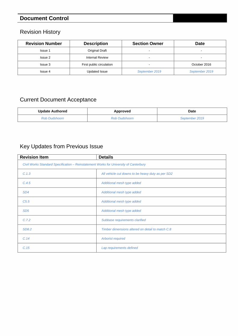
Revision History
Revision Number Description Section Owner Date
Issue 1 Original Draft - -
Issue 2 Internal Review - -
Issue 3 First public circulation - October 2016
Issue 4 Updated Issue September 2019 September 2019
Current Document Acceptance
Update Authored Approved Date
Rob Oudshoorn Rob Oudshoorn September 2019
Key Updates from Previous Issue
Revision Item Details
Civil Works Standard Specification – Reinstatement Works for University of Canterbury
C.1.3 All vehicle cut downs to be heavy duty as per SD2
C.4.5 Additional mesh type added
SD4 Additional mesh type added
C5.5 Additional mesh type added
SD5 Additional mesh type added
C.7.2 Subbase requirements clarified
SD8.2 Timber dimensions altered on detail to match C.8
C.14 Arborist required
C.15 Lap requirements defined
Contents
Overview 1
Purpose 1
Design Concepts 2
General 2
Design Options 2
Due Diligence Activities Options 2
Stormwater Design 2
Civil Works Elements 3
Sewer Drainage 3
Stormwater Drainage 3
Service Culverts 3
Landscaping Drainage 3
Standard Specification 3
Appendix A - Civil Works Standard Specification 5
Compliance Checklist 6

4.1 Overview
University of Canterbury – Section 04. Civil – Design Guidelines September 2019: Issue 4
Page 1 of 7
Overview
Purpose
The Civil section of the Design Standard Guidelines provides a reference document to support consistency across design and engineering objectives. The document provides guidance on the minimum performance standards for civil design, and ultimately aims to maximise the ability of the built environment to support the University’s long-term objectives.
This section of the Design Standard Guidelines is intended to be read and applied in conjunction with Section 01 – General and any project specific brief and agreements.

4.2 Design Concepts
University of Canterbury – Section 04. Civil – Design Guidelines September 2019: Issue 4
Page 2 of 7
Design Concepts
General
The following general design parameters should be considered during the civil design of works undertaken at the University.
Key requirements have been included wherever possible, however it is the responsibility of the civil consultant to identify any areas of ambiguity or omission and ensure that the overall design meets the overall performance intentions identified in this guideline.
The civil consultant shall coordinate with all other consultants engaged on the project to ensure requirements for aspects such as structure and architectural design are met within the civil scope of works. Where these consultants are not engaged on a project, the civil consultant shall flag any areas of concern or issues with compliance in these areas to the University of Canterbury Project Manager for discussion.
Design Options
The Consultant shall investigate design options such as ring mains, reservoir storage and pumping systems and provide recommendations of the most effective and efficient solution with respect to the University's present and future supply demands.
Due Diligence Activities Options
The civil consultant shall obtain all necessary data such as mains water pressures/flows etc. to assist system design and for the submission of design for approvals.
The consultant shall also provide full computer-designed hydraulic calculations to the satisfaction of the Regulatory Authorities and the University to support the selected design option.
Stormwater Design
Minimum Design Criteria
The stormwater system shall be designed for a minimum of the 100 years return rainfall intensity.
Stormwater Discharge
All stormwater discharges at the Ilam campus currently end up in two waterways; the Avon, and the Okeover.
All new works shall be the subject of a detailed assessment to ensure that these do not cause further degradation to the current fragile state of these waterways.
Additionally, every opportunity should be taken to improve the existing discharge conditions into these environments where practical.
Treatment
Large scale use of zinc or copper solutions on facades or roofs have been proven to transfer these heavy metals into the waterways.
These solutions should be avoided where ever possible, and if not they need to be treated at source before entering the site infrastructure to waterways.

4.3 Civil Works Elements
University of Canterbury – Section 04. Civil – Design Guidelines September 2019: Issue 4
Page 3 of 7
Civil Works Elements
Sewer Drainage
Generally heavy duty sewer class uPVC pipe and fittings are acceptable for all in-ground and suspended sewer drainage installation.
Sewer drainage receiving hot discharge and/or solvents shall be brass pipe and fittings or other approved material.
Inspection openings under concrete paving shall be extended to the finished level to provide access to the entire drainage installation.
Inspection chambers shall be provided at main junctions, changes in gradient and direction and at intervals not exceeding 60 metres.
Covers and frames to be "Gatic" cast iron type. Internally placed chambers shall be fitted with edge strips to accommodate floor finishes.
Step irons shall be provided in chambers exceeding 1.2 metres in depth.
Internal chamber drops shall be in cast iron pipe and fittings.
At least one overflow relief gully shall be provided for each building.
Test sumps to neutraliser pits and mixing tanks shall be easily accessible.
Placement of neutraliser tanks shall take into account the requirement for vehicular access where pumping out procedures are necessary. Associated dosing tanks shall be located where access can be gained independently of any laboratory or office areas. An adjacent cold water point shall also be provided for washing down purposes.
Stormwater Drainage
Underground stormwater drainage shall be rubber ring reinforced concrete class "X" pipe for sizes 300mm and greater in diameter. Pipes subjected to greater loadings or reduced cover shall be class "Y" or "Z" depending upon circumstances.
Underground stormwater drainage shall be sewer class uPVC pipes and fittings for sizes up to 300mm in diameter (minimum size of 100mm in diameter to be used).
Provide pits at changes in direction, grade, junctions and at spacing’s no more than 60 metres for pipes 225mm diameter or greater.
Provide inspection openings at changes in direction, grade and junctions for pipes 150mm diameter or greater. Extend selected inspection openings to finished level when pipes are located under concrete paving.
Provide grated pits at the base of all downpipes.
Pit covers, grates and frames to be "Gatic" cast iron type. The duty shall be dependent upon location.
Pits are to be either precast or in situ concrete. In situ concrete pits to have a minimum wall thickness of 150mm and placed using inner and outer forms. PVC or poly heavy duty pits may be used for PVC drains up to 150mm diameter.
Provide step irons in pits exceeding 1.2 metres in depth.
Consideration shall be made in the design to exclude garden mulch entering the drainage system causing blockages and reducing efficiency.
Service Culverts
Culverts shall be constructed of reinforced concrete cast in-situ or pre-cast and shall be provided with removable reinforced concrete lids fitted with substantial lifting eyes along the entire length.
The culverts shall be formed up internally and externally prior to casting.
Piping supports and fittings shall be galvanised. Pipe supports shall be installed in slots casing the culvert walls rather than by the use of masonry anchors. All supports should be 65mm clear of the floor of the culvert so as not to impede the flow of possible seepage water.
Lids on culverts should be sealed at sides and ends with an approved mastic compound. Notwithstanding, all culverts shall be laid to a grade and be provided with sumps and outlets for drainage.
Piping supports should not impede the free flow of seepage water along the floor of the culvert. All piping fittings including valves, expansion bellows and flanges shall be accessible from pits brought up to ground level.
Service culverts shall be provided with natural ventilation where there is a potential for culvert temperatures to exceed 50°C.
Landscaping Drainage
Provide sub-soil drainage to below ground building structures, back of kerbs and landscape areas where excessive ground water may be a problem.
Pipework for straight lengths shall be slotted rigid uPVC pipes and fittings and elsewhere shall be slotted flexible corrugated type pipe and purpose fittings. Pipe sizes shall be 100mm minimum diameter.
Pipework shall be surrounded in 150mm clean, washed, evenly graded, granular bedding material. The granular material and pipework shall be overwrapped with a geotextile layer to prevent fines entering the drainage system.
Standard Specification
Detailed guidance for the construction of other civil works elements at the University of Canterbury is to be as per the details in Appendix A - Civil Works Standard Specification.
The specification covers the following:
● Concrete kerb and channels
● commercial crossing
● concrete nib kerbs
● concrete paving in non-trafficked areas
● concrete paving in trafficked areas
● asphaltic concrete footpaths
● trafficked asphaltic concrete
● timber edging
● cobble paving with concrete edge restraint (epoxy)
● cobble paving with concrete edge restraint (butted)
● concrete pavers in non-trafficked areas
● concrete pavers in trafficked areas
● trenching/backfilling pipework
● works around protected trees
● saw-cutting existing reinforced concrete
● pavement crack filling
● erosion and sediment control

4.3 Civil Works Elements
University of Canterbury – Section 04. Civil – Design Guidelines September 2019: Issue 4
Page 4 of 7
CCC Construction Standard Specifications
The Civil Works Standard Specification references in detail the Christchurch City Council Construction Standard Specifications. It is the University’s expectation that designers and contractors working on civil works designs at the University are familiar with these documents.
Common Requirements for Construction
The following minimum requirements are generally applied in the Civil Works Standard Specification.
● Testing of all subgrade ground conditions to ensure a California Bearing Ratio (CBR) of greater than 7.
● On site measurements to confirm a minimum dry density of 98%, or 2200 kg/m3 of all compacted fill.
● Evidence that the concrete used has a slump of 80mm and a 28 day compressive strength of 20 Mpa.
● The contractor is to provide documentation that the above three requirements have been met (as a minimum).
Designers and contractors should check to ensure that higher or additional requirements are not prescribed elsewhere in this design guideline or the appendixed specification.
Appendix A - Civil Works Standard Specification
University of Canterbury – Section 04. Civil – Design Guidelines September 2019: Issue 4
Page 5 of 7
Appendix A - Civil Works Standard Specification
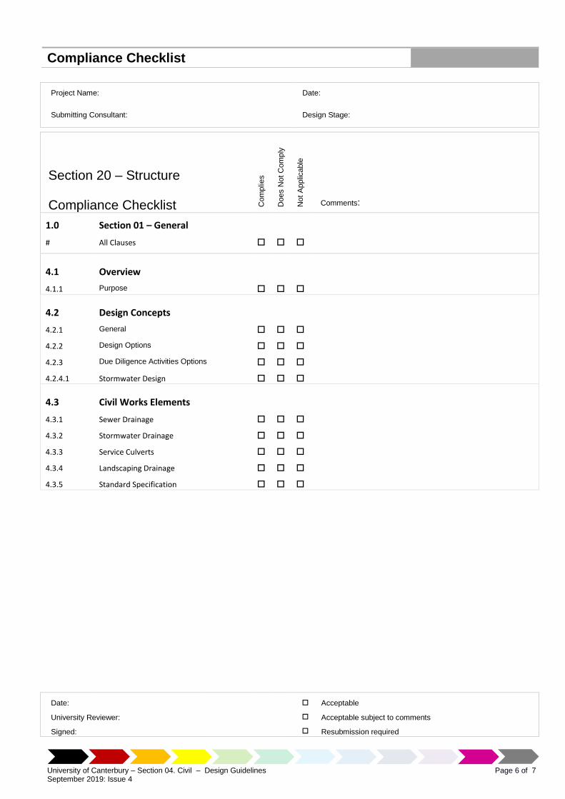
Compliance Checklist
University of Canterbury – Section 04. Civil – Design Guidelines September 2019: Issue 4
Page 6 of 7
Project Name: Date:
Submitting Consultant: Design Stage:
Section 20 – Structure
Compliance Checklist Com
plie
s
Does N
ot C
om
ply
Not
Applic
able
Comments:
1.0 Section 01 – General
# All Clauses
4.1 Overview
4.1.1 Purpose
4.2 Design Concepts
4.2.1 General
4.2.2 Design Options
4.2.3 Due Diligence Activities Options
4.2.4.1 Stormwater Design
4.3 Civil Works Elements
4.3.1 Sewer Drainage
4.3.2 Stormwater Drainage
4.3.3 Service Culverts
4.3.4 Landscaping Drainage
4.3.5 Standard Specification
Date:
University Reviewer:
Signed:
Acceptable
Acceptable subject to comments
Resubmission required