section 3 max+plus ii tutorial - intel · in addition, sessions 5 and 9 introduce you to command...
TRANSCRIPT

81_GSBOOK.fm5 Page 155 Tuesday, October 14, 1997 4:04 PM
Section
3
MAX+PLUS IITutorial
This tutorial demonstrates the basic features of MAX+PLUS II.
■ Introduction............................................................................................. 156Project Description....................................................................... 157Tutorial Overview........................................................................ 160Getting Help ................................................................................. 162
■ Design EntrySession 1: Start a MAX+PLUS II Session .................................. 165Session 2: Create a Graphic Design File.................................... 168Session 3: Create Two Text Design Files................................... 185Session 4: Create a Waveform Design File ............................... 196Session 5: Create the Top-Level Graphic Design File ............. 210
■ Project ProcessingSession 6: Compile the Project.................................................... 216Session 7: View the Project in the Hierarchy Display............. 229Session 8: View the Fit in the Floorplan Editor........................ 231
■ Project VerificationSimulation Overview................................................................... 242Session 9: Create a Simulator Channel File .............................. 245Session 10: Simulate the Project ................................................. 255Session 11: Analyze Simulation Outputs.................................. 261Session 12: Analyze Timing........................................................ 266
■ Device ProgrammingSession 13: Program an Altera Device ...................................... 273
■ Are We There Yet? .................................................................................. 276
Altera Corporation 155

MAX+PLUS II Getting Started
81_GSBOOK.fm5 Page 156 Tuesday, October 14, 1997 4:04 PM
Introduction
MAX+PLUS II is easyÑeasy to learn, easy to use, and very easy to like. This tutorial introduces you to the basic features of the fully integrated MAX+PLUS II design environment, so youÕll be able to create your own logic designs in record time. Once you start using MAX+PLUS II, the on-line help (always just a mouse-click away) can fill in all the details.
In this tutorial, you will create a design (called a ÒprojectÓ in MAX+PLUS II) named chiptrip, a simple driving simulator. After you enter and compile the chiptrip project, you will simulate it. In the simulation sessions, you will guide your ÒvehicleÓ through an imaginary street map. Your challenge will be to drive from your company to Altera using the most direct route without getting tickets from the police. Once you finish the simulation task, your final step will be to program your completed project into an Altera device.
156 Altera Corporation

Section 3: MAX+PLUS II Tutorial
81_GSBOOK.fm5 Page 157 Tuesday, October 14, 1997 4:04 PM
The tutorial is divided into four sections: creating the actual logic circuit, compiling it, simulating it with multiple sets of inputs, and then programming an Altera device. To accommodate your level of expertise and to make sure that you experience some driving pleasure on the way (remember Fahrvergn�gen?), all files for this project are provided in the \max2work\chiptrip directory. Thus, you can choose to go through every single step of the tutorial or take one or more shortcuts by copying the ready-made files to your working directory. Since the tutorial is divided into logical chunks, you can stop at any time and continue later. Have a good trip!
Project Description
The chiptrip tutorial takes you through all major steps of design entry, compilation, simulation, and programming for a hierarchical project.
Design Entry & Project Processing
You will create five design files using text, graphic, and waveform design entry. This tutorial describes a Òbottom-upÓ hierarchical design entry method, in which you create the lower-level designs first and then combine them in a single top-level design file to create the chiptrip project. A project consists of all files associated with a particular design, including all subdesign files and ancillary files; the project name is always the same as the name of the top-level design file, without the filename extension. In the chiptrip project, the top-level Graphic Design File (.gdf), chiptrip.gdf, incorporates four lower-level design filesÑa GDF, two Text Design Files (.tdf), and a Waveform Design File (.wdf). Each lower-level file performs a specific function in the driving simulation game:
■ The tick_cnt.gdf file, your Òdriving record,Ó counts the number of police citations you collect as you drive. This counter adds up the number of tickets issued for ÒillegalÓ speeds in auto_max.tdf and speed_ch.wdf.
■ The time_cnt.tdf file, the ÒclockÓ in your car, counts the number of clock pulses required for the vehicle to reach Altera.
■ The auto_max.tdf file, your Òautomobile,Ó contains a state machine that monitors the direction and acceleration inputs to the project and determines the next location (i.e., state) of the vehicle.
Altera Corporation 157

MAX+PLUS II Getting Started
81_GSBOOK.fm5 Page 158 Tuesday, October 14, 1997 4:04 PM
■ The speed_ch.wdf file, your Òspeedometer,Ó is a state machine that checks the acceleration of the vehicle. Illegal speeds result in a speeding ticket.
1 If you have not purchased the waveform design entry feature for MAX+PLUS II, you can use a TDF version of the speed_ch.wdf file, called speed_ch.tdf. This file is available in the \max2work\chiptrip subdirectory.
Figure 3-1 shows a block diagram of the chiptrip project:
Figure 3-1. Block Diagram of chiptrip
After you have created the design files, you must successfully compile your project to generate the files you need to simulate chiptrip and program a device.
chiptrip.gdf
tick_cnt.gdf time_cnt.tdf auto_max.tdf
8count.gdf
speed_ch.wdf
158 Altera Corporation

Section 3: MAX+PLUS II Tutorial
81_GSBOOK.fm5 Page 159 Tuesday, October 14, 1997 4:04 PM
Project Verification & Device Programming
The simulation portion of the tutorial is a driving game. The game tests your ability to plan and modify your simulation inputs to complete a specific task. Your goal is to navigate your vehicle through different intersections on a map (shown in Figure 3-2) to arrive at Altera as fast as you can and with as few speeding tickets as possible. Depending on how you edit your simulation inputs, you can maneuver your car along expressways, commercial roads, or residential streets.
Figure 3-2. Map to Altera
On expressways, you can go as fast as you like without worrying about any police officers stopping you. On commercial roads, you can accelerate once without getting a speeding ticket, but you will definitely get caught the second time. If you accelerate at all on residential streets, however, you will get a ticket right away. Just remember, in this design logic universe, police officers are everywhere, they always know when you are speeding, and you canÕt talk them out of giving you a ticket.
After you practice simulating your project with multiple sets of input vectors and analyzing its timing to your satisfaction, you can then program the chiptrip project into an Altera device.
YC
RPT
MPLD
EPLD
GDF CNF
EPM
Your Company
Residential Street: Normal speedonly; any acceleration results in aspeeding ticket.
Commercial Road: Acceleratingfor two Clock cycles results in aticket. Clock cycles can be non-consecutive.
Expressway: Any number ofaccelerations is allowed.
Altera Corporation 159

MAX+PLUS II Getting Started
81_GSBOOK.fm5 Page 160 Tuesday, October 14, 1997 4:04 PM
Tutorial Overview
The chiptrip tutorial is designed to help you become an expert MAX+PLUS II user quickly and easily. The tutorial is modular, so you can complete the sessions at your own pace; work through one session at a time, or the whole tutorial in one sitting. You can also adapt the tutorial to your level of expertise. For example, if you feel comfortable with the various design entry methods, you can skip one or more of the sessions and move straight on to compiling and simulating your project. In addition, Sessions 5 and 9 introduce you to command shortcuts that can help you develop more efficient design entry skills.
Tutorial Files
All tutorial files are copied to your hard disk during MAX+PLUS II installation. The MAX+PLUS II working directory, which has the default name \max2work, contains the chiptrip and tutorial subdirectories. The \max2work\chiptrip subdirectory contains all design files, as well as user- and MAX+PLUS II-generated files for this tutorial. To prevent changes to the original files, you should create your project in the \max2work\tutorial subdirectory. If you do not wish to create an entire design file from scratch, you can simply copy the desired file from the \max2work\chiptrip subdirectory into the \max2work\tutorial subdirectory without running the risk of accidentally overwriting the original tutorial files installed on your hard disk. You can copy files with the appropriate copying command for your operating system, or open a file in MAX+PLUS II and choose Save As (File menu) to save a copy of the file in a different directory.
1 1. Be sure to refer to the read.me file in the \max2work\tutorial directory for information on changes to the chiptrip tutorial since this manual was printed.
2. On a UNIX workstation, the max2work directory is a subdirectory of the /usr directory.
Command Shortcuts
Many MAX+PLUS II commands have a variety of shortcuts. These shortcuts are often context-sensitive, that is, the options available depend on the position of the mouse pointer or on the item(s) selected on screen. Although you can use shortcuts at any stage of the tutorial process, Sessions 5 and 9 provide you with specific alternative steps to help speed up design entry.
160 Altera Corporation
Section 3: MAX+PLUS II Tutorial
81_GSBOOK.fm5 Page 161 Tuesday, October 14, 1997 4:04 PM
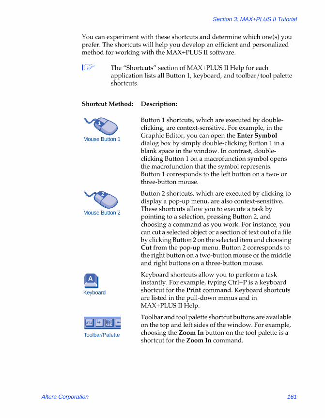
You can experiment with these shortcuts and determine which one(s) you prefer. The shortcuts will help you develop an efficient and personalized method for working with the MAX+PLUS II software.
1 The ÒShortcutsÓ section of MAX+PLUS II Help for each application lists all Button 1, keyboard, and toolbar/tool palette shortcuts.
Shortcut Method: Description:
Button 1 shortcuts, which are executed by double-clicking, are context-sensitive. For example, in the Graphic Editor, you can open the Enter Symbol dialog box by simply double-clicking Button 1 in a blank space in the window. In contrast, double-clicking Button 1 on a macrofunction symbol opens the macrofunction that the symbol represents. Button 1 corresponds to the left button on a two- or three-button mouse.
Button 2 shortcuts, which are executed by clicking to display a pop-up menu, are also context-sensitive. These shortcuts allow you to execute a task by pointing to a selection, pressing Button 2, and choosing a command as you work. For instance, you can cut a selected object or a section of text out of a file by clicking Button 2 on the selected item and choosing Cut from the pop-up menu. Button 2 corresponds to the right button on a two-button mouse or the middle and right buttons on a three-button mouse.
Keyboard shortcuts allow you to perform a task instantly. For example, typing Ctrl+P is a keyboard shortcut for the Print command. Keyboard shortcuts are listed in the pull-down menus and in MAX+PLUS II Help.
Toolbar and tool palette shortcut buttons are available on the top and left sides of the window. For example, choosing the Zoom In button on the tool palette is a shortcut for the Zoom In command.
Mouse Button 1
1
Mouse Button 2
2
Keyboard
A
Toolbar/Palette
Altera Corporation 161

MAX+PLUS II Getting Started
81_GSBOOK.fm5 Page 162 Tuesday, October 14, 1997 4:04 PM
Getting Help
Throughout the tutorial, you can follow the footprints ( f ) for useful references to MAX+PLUS II Help. On-line help provides the most up-to-date and complete information on all MAX+PLUS II features. Two of the easiest ways to get on-line help are by using the context-sensitive help feature and the search index.
Context-Sensitive Help
Context-sensitive help gives you instant help when you need it. You can access context-sensitive help in three ways:
Method: Description:
Shift+F1 or the context-sensitive help toolbar button h
Position the question-mark pointer over an item on the screen, a text file keyword, or a menu command, then click Button 1 on it to obtain help.
F1 key When a menu command is highlighted, a dialog box is open, or a pop-up message box is displayed, press F1 to obtain help. You can also press F1 when any MAX+PLUS II application window is displayed to obtain general information about the context-sensitive help available for that application.
Help on Message button In the Message Processor window, you can select a message with Button 1 and choose the Help on Message button to display help on that message.
162 Altera Corporation

Section 3: MAX+PLUS II Tutorial
81_GSBOOK.fm5 Page 163 Tuesday, October 14, 1997 4:04 PM
Search Index
MAX+PLUS II Help includes an extensive on-line index to help you find information fast. To search for a Help topic:
1. If you are in MAX+PLUS II, choose Search for Help on (Help menu).
or:
If you are already in Help, choose the Index button at the top of the Help window (called Search in Windows NT 3.51).
The Help Topics dialog box is displayed. (In Windows NT 3.51, the Search dialog box, which functions in a similar manner, appears instead of the Help Topics dialog box.)
2. Type a keyword or phrase. The keyword list scrolls to display the keywords that match the text you type, as shown in the following illustration:
Altera Corporation 163

MAX+PLUS II Getting Started
81_GSBOOK.fm5 Page 164 Tuesday, October 14, 1997 4:04 PM
3. Click Button 1 on a keyword to select it and choose the Display button or double-click Button 1 on the keyword to go to the topic associated with the keyword. If multiple topics exist, they are displayed in the Topics Found dialog box, as shown in the following illustration:
4. Select a topic name from the list and choose the Display button or double-click Button 1 on a topic name to display the topic.
164 Altera Corporation

Section 3: MAX+PLUS II Tutorial
81_GSBOOK.fm5 Page 165 Tuesday, October 14, 1997 4:04 PM
Session 1: Start a MAX+PLUS II Session
In this session, you will start MAX+PLUS II to begin creating your project.
1 This tutorial assumes that the MAX+PLUS II working directory, which has the default name \max2work, appears on the d: drive on your computer. If you installed the MAX+PLUS II working directory in a different drive and/or directory, substitute the appropriate drive and/or directory name.
To start MAX+PLUS II:
1. Double-click Button 1 on the MAX+PLUS II icon. On a PC running Windows, this icon appears in the MAX+PLUS II program group in the Program Manager window.
or:
Type maxplus2 9 at the command line.
The MAX+PLUS II Manager window opens. The title bar displays the name of the program (MAX+PLUS II), and a drive and directory name (d:\max2work\tutorial). The current project name, chiptrip, is appended to the drive and directory names.
Altera Corporation 165
MAX+PLUS II Getting Started
81_GSBOOK.fm5 Page 166 Tuesday, October 14, 1997 4:04 PM
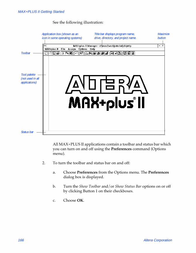
See the following illustration:
All MAX+PLUS II applications contain a toolbar and status bar which you can turn on and off using the Preferences command (Options menu).
2. To turn the toolbar and status bar on and off:
a. Choose Preferences from the Options menu. The Preferences dialog box is displayed.
b. Turn the Show Toolbar and/or Show Status Bar options on or off by clicking Button 1 on their checkboxes.
c. Choose OK.
Toolbar
Status bar
Application box (shown as an icon in some operating systems)
Title bar displays program name, drive, directory, and project name.
Maximize button
Tool palette (not used in all applications)
166 Altera Corporation

Section 3: MAX+PLUS II Tutorial
81_GSBOOK.fm5 Page 167 Tuesday, October 14, 1997 4:04 PM
The toolbar displays buttons and drop-down list boxes that provide quick access to frequently used commands. (Additional buttons are available on the tool palette in some applications.) The status bar provides a brief description of a highlighted menu command or an item in the toolbar or tool palette when you move the mouse pointer over it.
1 In some MAX+PLUS II applications, items on the far right of the toolbar are unavailable if your monitor is set to VGA display mode. All toolbar buttons and drop-down lists are available in larger screen displays.
If you wish, you can switch to an alternate combination of toolbar buttons for VGA displays. Go to ÒSetting MAX+PLUS II PreferencesÓ using Search for Help on (Help menu) for instructions.
3. Maximize the MAX+PLUS II window by clicking Button 1 on the Maximize button, as shown in the illustration on page 166.
1 If you wish to exit MAX+PLUS II, choose Exit MAX+PLUS II (File menu) or double-click Button 1 on the application icon (or box) in the top left corner of the MAX+PLUS II window, as shown in the illustration on page 166.
Altera Corporation 167

MAX+PLUS II Getting Started
81_GSBOOK.fm5 Page 168 Tuesday, October 14, 1997 4:04 PM
Session 2: Create a Graphic Design File
In this session, you will specify the project name and use the MAX+PLUS II Graphic Editor to enter and save tick_cnt.gdf, which counts the number of speeding tickets you collect during your trip. This session includes the following steps:
1. Create a new file.2. Specify the project name.3. Select a palette tool.4. Enter logic function symbols.5. Set and show guidelines.6. Move a symbol.7. Enter input and output pins.8. Name the pins.9. Connect the symbols.10. Connect nodes and buses by name.11. Save the file and check for basic errors.12. Create a default symbol.13. Close the file.
1 Remember, all files for the chiptrip tutorial are available in the \max2work\chiptrip subdirectory.
1. Create a New File
In this step, you will create a new GDF called tick_cnt.gdf.
To create the file:
1. Choose New (File menu). The New dialog box is displayed.
2. Select Graphic Editor file.
3. Select the .gdf filename extension in the drop-down list box.
4. Choose OK.
An untitled Graphic Editor window opens, as shown in the following illustration:
168 Altera Corporation

Section 3: MAX+PLUS II Tutorial
81_GSBOOK.fm5 Page 169 Tuesday, October 14, 1997 4:04 PM
5. If necessary, maximize the Graphic Editor window by clicking Button 1 on the Maximize button in the Graphic Editor title bar.
6. To save the file, choose Save As (File menu). The Save As dialog box is displayed, as shown in the following illustration:
Workspace Maximize button
Selection tool
Circle tool
Toggle Connection Dot button
Diagonal Line tool
Rubberbanding On button Rubberbanding Off
button
Arc tool
Zoom In buttonZoom Out button
Fit in Window button
Orthogonal Line tool
Text tool
Specifies the nameof the file.
Displays the default extension for the current file type. You can select a different extension from the drop-down list.
Altera Corporation 169

MAX+PLUS II Getting Started
81_GSBOOK.fm5 Page 170 Tuesday, October 14, 1997 4:04 PM
7. Type tick_cnt.gdf in the File Name box.
8. If \max2work\tutorial does not appear in the Directory is field as the current directory, select it in the Directories box.
9. Choose OK to save the tick_cnt.gdf file.
2. Specify the Project Name
In MAX+PLUS II, you must specify a design file as your current project before you can compile it or perform any other batch processing such as simulation. MAX+PLUS II processes one project at a time, and you must ensure that all design files in a project appear in that projectÕs hierarchy. You should always create a separate subdirectory for each new project. When you enter the project name, you also specify the name of the subdirectory where the project will be stored. If the subdirectory does not exist, MAX+PLUS II can create it for you.
To specify the project name:
1. Choose Project Name (File menu). The Project Name dialog box is displayed:
2. If necessary, turn off the Show Only Tops of Hierarchies option.
Lists all designfiles and programming files in the current directory.
Shows currentproject name.
Shows currentdirectory path.
Lists all subdirectories.
Lists all local and network drives.
170 Altera Corporation

Section 3: MAX+PLUS II Tutorial
81_GSBOOK.fm5 Page 171 Tuesday, October 14, 1997 4:04 PM
3. Select tick_cnt.gdf in the Files box.
4. Choose OK.
The MAX+PLUS II title bar changes to display the new project name:
MAX+plus II Manager - d:\max2work\tutorial\tick_cnt
1 As an alternative to using the Project Name command, you can simply choose the Project Set Project to Current File command (File menu) when tick_cnt.gdf is open in the active Graphic Editor window.
3. Select a Palette Tool
In this step, you will select from the various palette tools available for the Graphic Editor. In the Graphic, Symbol, and Waveform Editors, the pointer changes shape, depending upon the current selected palette tool and the object under the mouse pointer. The Selection tool, which has an arrow-shaped pointer, is the default palette tool when you first open a Graphic Editor window. As an exercise, you will select the Orthogonal Line tool from the tool palette.
To select the Orthogonal Line tool from the palette:
v Click Button 1 on the Orthogonal Line tool, as shown in the illustration on page 169.
The pointer changes into a +-shaped pointer if you select the Orthogonal, Diagonal, Arc, or Circle tool. If you select the Text tool, the pointer is an inverted ÒtÓ that changes into an I-shaped pointer when it passes over editable text.
Altera Corporation 171

MAX+PLUS II Getting Started
81_GSBOOK.fm5 Page 172 Tuesday, October 14, 1997 4:04 PM
The Selection tool is a ÒsmartÓ tool. When this tool is selected, the arrow-shaped Selection pointer automatically changes into the Orthogonal Line drawing or Text Editing pointer when it passes over different objects in the Graphic Editor window:
■ When the Selection pointer passes over the end of a line, a connection dot, or a symbol pinstub, it changes into the +-shaped Orthogonal Line drawing pointer, which allows you to draw lines and enter or delete connection dots. This ÒsmartÓ behavior means that you need to select a line drawing tool from the tool palette only if you wish to draw lines in empty space.
■ When you double-click Button 1 on editable text, the Selection pointer changes into the I-shaped Text Editing pointer, which allows you to edit pin and node names, pin default values, and comments. This ÒsmartÓ behavior means that you need to select the Text tool from the tool palette only if you wish to enter text in empty space.
■ When the pointer passes over empty space, over the middle of a line or symbol, or over text, the Selection pointer has normal selection behavior, which allows you to select, move, and copy objects in the window.
4. Enter Logic Function Symbols
MAX+PLUS II provides symbols for a variety of logic functionsÑincluding primitive, megafunction, and macrofunction symbolsÑthat you can use in your Graphic Editor files.
To enter a symbol:
1. With the Selection pointer, click Button 1 in empty space in the Graphic Editor window to define an insertion point and choose Enter Symbol (Symbol menu).
172 Altera Corporation

Section 3: MAX+PLUS II Tutorial
81_GSBOOK.fm5 Page 173 Tuesday, October 14, 1997 4:04 PM
The Enter Symbol dialog box is displayed:
SHORTCUTS Double-clicking Button 1 in a blank space in the Graphic Editor window is a shortcut for this step. This action both defines an insertion point and opens the Enter Symbol dialog box.
1 Command shortcuts are described in more detail in Sessions 5 and 9 of this tutorial.
2. Type 8count in the Symbol Name box.
3. Choose OK. The 8count symbol is entered with its top left corner at the insertion point. The 8count macrofunction is an 8-bit up/down binary counter. In tick_cnt.gdf, four bits of the 8count macrofunction will be used to count the number of tickets received by the driver.
4. Repeat steps 1 through 3 to enter the NOR2 and GND primitives to the left of the 8count symbol.
1 MAX+PLUS II documentation conventions use all capital letters for primitive names. However, you should type all primitive, megafunction, and macrofunction names with lowercase letters in the Enter Symbol dialog box.
Specifies the name of a symbol to be entered in your file.
Double-clicking Button 1 on a symbol library directory lists its contents in the Symbol Files box. MAX+PLUS II automatically searches each listed directory for a symbol when you type a symbol name in the Symbol Name box and choose OK.
Lists all symbols in the current directory.
Altera Corporation 173

MAX+PLUS II Getting Started
81_GSBOOK.fm5 Page 174 Tuesday, October 14, 1997 4:04 PM
See the following illustration:
1 If you enter or move two symbols so that their borders and pinstubs touch, the symbols become logically connected. If you then move one of the symbols when Rubberbanding (Options menu) is turned on, a new node or bus line forms automatically between the connected pinstubs of the two symbols.
f Choose h from the toolbar and click Button 1 on the 8count, NOR2, or GND symbols for information on each. On-line help provides complete information on all Altera-provided primitives, megafunctions, and macrofunctions.
You can also get help on megafunctions, primitives, and macrofunctions by choosing Megafunctions/LPM, Primitives, or Old-Style Macrofunctions, respectively, from the Help menu.
5. Set & Show Guidelines
To increase the readability of your schematic, you can align symbols to horizontal and vertical guidelines. You can specify the guideline spacing and display or hide the guidelines.
Rubberbanding On button Rubberbanding
Off button
174 Altera Corporation

Section 3: MAX+PLUS II Tutorial
81_GSBOOK.fm5 Page 175 Tuesday, October 14, 1997 4:04 PM
To set the spacing and show the guidelines:
1. Choose Guideline Spacing from the Options menu. The Guideline Spacing dialog box is displayed.
2. Type 15 in both the X (Horizontal) Spacing and Y (Vertical) Spacing boxes to specify 15 grid-unit spacing between guidelines.
3. Choose OK.
4. Turn on Show Guidelines (Options menu). When the command is turned on, a checkmark appears next to the command name in the menu. The guidelines appear as shown in the following illustration:
1 As you edit your schematic, you can change the window display to view larger or smaller portions of the file by choosing the Zoom In, Zoom Out, and Fit in Window buttons on the tool palette, as shown in the previous illustration.
Guidelines spaced 15 grid units apart.
Zoom In button
Fit in Window button
Zoom Out Button
Altera Corporation 175

MAX+PLUS II Getting Started
81_GSBOOK.fm5 Page 176 Tuesday, October 14, 1997 4:04 PM
6. Move a Symbol
To move and align the 8count symbol:
1. With the Selection pointer, press or click Button 1 on 8count to select the symbol.
2. While pressing Button 1, drag the symbol and position the top left corner of 8count at the closest guideline intersection. An outline of the symbol moves with the pointer so that you can position it accurately.
3. Once the symbol is in position, release Button 1.
1 You can move any symbol, graphic, or block of text that can be selected with Button 1 in the MAX+PLUS II Graphic or Symbol Editor by dragging it with the Selection pointer.
f Go to ÒMoving an ObjectÓ and ÒSelecting an ObjectÓ using Search for Help on (Help menu).
7. Enter Input & Output Pins
To enter the INPUT and OUTPUT pins:
1. With the Selection pointer, double-click Button 1 in an empty space to the left of the 8count symbol to open the Enter Symbol dialog box, type input in the Symbol Name box, and choose OK. The INPUT pin symbol is displayed.
2. Press Ctrl and then press Button 1 on the INPUT symbol. While holding Ctrl and Button 1 down, drag the mouse down to create a copy of the symbol and place it below the original. (The symbol is copied but not placed on the Clipboard.)
3. Repeat step 2 to create the third INPUT symbol.
4. Repeat step 1 to enter the OUTPUT symbol below the 8count symbol.
176 Altera Corporation

Section 3: MAX+PLUS II Tutorial
81_GSBOOK.fm5 Page 177 Tuesday, October 14, 1997 4:04 PM
See the following illustration:
A symbol identification number is located at the bottom left corner of each symbol. It is automatically assigned based on the order in which you enter the symbols (i.e., the first symbol entered is assigned the ID number 1). It uniquely identifies each instance of a symbol within the GDF. The symbol ID numbers in your file may differ from those in the illustrations, depending on the order in which you enter the symbols. However, these differences will not cause any errors.
8. Name the Pins
You will now name the input and output pins. Symbols in this procedure are identified as <symbol name>:<symbol ID>, e.g., INPUT:4 is the INPUT symbol with the symbol ID number 4, as entered in the previous step.
1 If you did not enter the symbols in the described sequence, your symbol ID numbers will differ from those in the illustration. These differences will not cause any errors.
Each symbol has an ID number that uniquely identifies it. These ID numbers are based on the order in which symbols are entered.
4
5
6
7 12 3
Altera Corporation 177

MAX+PLUS II Getting Started
81_GSBOOK.fm5 Page 178 Tuesday, October 14, 1997 4:04 PM
To assign a pin name:
1. With the Selection pointer, double-click Button 1 on the default pin name ÒPIN_NAMEÓ of INPUT:4 to select the entire name.
2. Type get_ticket1. The new name replaces the default pin name. The get_ticket1 signal will be used to enable the counter. When it goes high, the count value will increment by one.
1 You can also use the Text tool to edit and enter text. Double-click Button 1 to select the entire name, or drag Button 1 to select a portion of the name you wish to edit.
3. Rename the remaining INPUT and OUTPUT pins as shown in the following list. If you press 9 after you edit a pin name, the next pin name below it is automatically selected for editing.
Primitive: Name: Description:
INPUT:5 get_ticket2 Same as get_ticket1.
INPUT:6 clk This signal is the Clock for the tick_cnt.gdf counter.
OUTPUT:7 ticket[3..0] These signals represent the counter bit outputs. The name is given in single-range bus name format, which is used to create an array of four output pins. In this case, ticket[3..0] is the bus that represents the pins ticket3, ticket2, ticket1, and ticket0.
178 Altera Corporation

Section 3: MAX+PLUS II Tutorial
81_GSBOOK.fm5 Page 179 Tuesday, October 14, 1997 4:04 PM
See the following illustration:
f Go to ÒPin & Node NamesÓ and ÒBus NamesÓ using Search for Help on (Help menu).
9. Connect the Symbols
You can use the ÒsmartÓ Selection tool to draw most of the lines you need to connect symbols in a Graphic Editor fileÑthe Selection pointer automatically turns into the Orthogonal Line drawing pointer when it is over a pinstub or connection dot, or at the end of a line. You can also use the Orthogonal and Diagonal Line tools to connect symbols.
To draw a line:
1. With the Selection pointer, move symbols so they line up with the appropriate pinstubs or other symbols, as shown in the preceding illustration.
2. Choose the solid line style from the top of the Line Style submenu (Options menu). This line style is the recommended line style for nodes.
Altera Corporation 179
MAX+PLUS II Getting Started
81_GSBOOK.fm5 Page 180 Tuesday, October 14, 1997 4:04 PM
3. Point to the output pinstub of the get_ticket1 input pin. The Selection pointer turns into the +-shaped Orthogonal Line drawing pointer when it is close to the pinstub.
4. Press Button 1 to define the start of a line.
5. While pressing Button 1, drag the mouse to draw a line that connects to the uppermost input pinstub on the NOR2 gate.
6. Release Button 1.
1 With the Orthogonal Line drawing pointer, you can draw straight lines or lines with a single bend. If you cannot draw a straight line or a line with a single bend to connect two symbols, you must draw two lines to create the two bends needed to make the connection. After you draw the first line, draw a second line that connects to the end of the first. Lines merge automatically if they have the same line style.
If you need to delete a line, click Button 1 on the line to select it and press the Del or Backspace key.
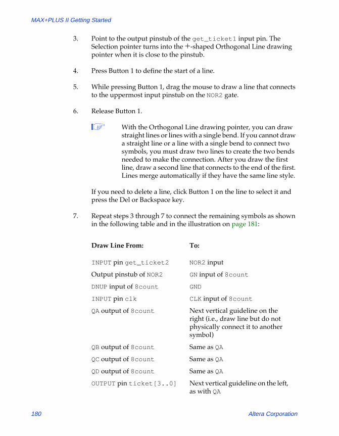
7. Repeat steps 3 through 7 to connect the remaining symbols as shown in the following table and in the illustration on page 181:
Draw Line From: To:
INPUT pin get_ticket2 NOR2 input
Output pinstub of NOR2 GN input of 8count
DNUP input of 8count GND
INPUT pin clk CLK input of 8count
QA output of 8count Next vertical guideline on the right (i.e., draw line but do not physically connect it to another symbol)
QB output of 8count Same as QA
QC output of 8count Same as QA
QD output of 8count Same as QA
OUTPUT pin ticket[3..0] Next vertical guideline on the left, as with QA
180 Altera Corporation

Section 3: MAX+PLUS II Tutorial
81_GSBOOK.fm5 Page 181 Tuesday, October 14, 1997 4:04 PM
The line that extends from the ticket[3..0] output pin should be a bus line. To change the line into a bus line:
1. Point to the line that extends from the output pin named ticket[3..0] and click Button 1 to select the line.
2. Choose the bus line style, i.e., the thick line style, from the Line Style submenu (Options menu).
See the following illustration:
f Choose h from the toolbar and click Button 1 on the bus line to go to ÒBusesÓ in MAX+PLUS II Help.
Bus line Single-range bus pin name creates an array of 4 pins.
Altera Corporation 181
MAX+PLUS II Getting Started
81_GSBOOK.fm5 Page 182 Tuesday, October 14, 1997 4:04 PM
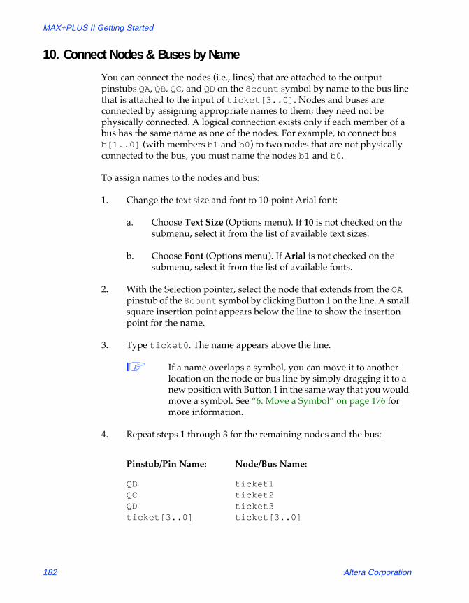
10. Connect Nodes & Buses by Name
You can connect the nodes (i.e., lines) that are attached to the output pinstubs QA, QB, QC, and QD on the 8count symbol by name to the bus line that is attached to the input of ticket[3..0]. Nodes and buses are connected by assigning appropriate names to them; they need not be physically connected. A logical connection exists only if each member of a bus has the same name as one of the nodes. For example, to connect bus b[1..0] (with members b1 and b0) to two nodes that are not physically connected to the bus, you must name the nodes b1 and b0.
To assign names to the nodes and bus:
1. Change the text size and font to 10-point Arial font:
a. Choose Text Size (Options menu). If 10 is not checked on the submenu, select it from the list of available text sizes.
b. Choose Font (Options menu). If Arial is not checked on the submenu, select it from the list of available fonts.
2. With the Selection pointer, select the node that extends from the QA pinstub of the 8count symbol by clicking Button 1 on the line. A small square insertion point appears below the line to show the insertion point for the name.
3. Type ticket0. The name appears above the line.
1 If a name overlaps a symbol, you can move it to another location on the node or bus line by simply dragging it to a new position with Button 1 in the same way that you would move a symbol. See Ò6. Move a SymbolÓ on page 176 for more information.
4. Repeat steps 1 through 3 for the remaining nodes and the bus:
Pinstub/Pin Name: Node/Bus Name:
QB ticket1QC ticket2QD ticket3ticket[3..0] ticket[3..0]
182 Altera Corporation

Section 3: MAX+PLUS II Tutorial
81_GSBOOK.fm5 Page 183 Tuesday, October 14, 1997 4:04 PM
See the following illustration:
Once you have assigned these names, the nodes ticket3, ticket2, ticket1, and ticket0 are automatically connected to the bus ticket[3..0] by name, even though they are not physically connected.
11. Save the File & Check for Basic Errors
To ensure that you have entered the logic correctly, you can save the file and check for simple errors.
To save the file and check for errors:
1. Choose Project Save & Check from the File menu. The file is saved and the MAX+PLUS II Compiler window opens; the Compiler Netlist Extractor module checks the file for errors, updates the Hierarchy Display, and displays a message indicating the number of errors and warnings.
2. If Project Save & Check is successful and there are no errors or warnings, choose OK to close the message box.
Document box (shown as an icon in some operating systems)
Altera Corporation 183

MAX+PLUS II Getting Started
81_GSBOOK.fm5 Page 184 Tuesday, October 14, 1997 4:04 PM
1 If the Compiler issues any error or warning messages and the Message Processor window is not automatically displayed, you can open it by choosing Message Processor (MAX+PLUS II menu). Select a message in the Message Processor window and choose Locate to find its source(s) or choose Help on Message to get an explanation. See Ò10. Locate the Source of a MessageÓ on page 226 for more information. You should correct any errors in your design file, and save and check it until it is error-free.
3. Double-click Button 1 on the document icon (or box), as shown in the illustration on page 183, to close the Compiler window and return to the Graphic Editor.
12. Create a Default Symbol
You will now create a Symbol File (.sym) that represents the current file. The symbol in this file can be used in any other Graphic Design File (.gdf).
To create a default symbol:
v Choose Create Default Symbol (File menu). If a symbol for a Þle already exists, MAX+PLUS II asks you whether it is OK to overwrite the existing symbol. Choose OK to ensure that you have the most up-to-date information in your Symbol File.
13. Close the File
To close the tick_cnt.gdf file:
v Choose Close from the File menu or double-click Button 1 on the document icon (or box), as shown in the illustration on page 183. The Graphic Editor window displaying the tick_cnt.gdf Þle closes automatically.
184 Altera Corporation

Section 3: MAX+PLUS II Tutorial
81_GSBOOK.fm5 Page 185 Tuesday, October 14, 1997 4:04 PM
Session 3: Create Two Text Design Files
In this session, you will use the MAX+PLUS II Text Editor to enter and save two Text Design Files (.tdf) written in the Altera Hardware Description Language (AHDL). The first TDF, time_cnt.tdf, measures the time it takes for your vehicle to reach Altera by counting Clock pulses. The auto_max.tdf file describes the functions of the street_map state machine, and determines the direction and acceleration of your automobile. This session includes the following steps:
1. Create a new file and specify the project name.2. Turn on syntax coloring.3. Enter the design name, inputs, and outputs.4. Declare a register.5. Enter Boolean equations.6. Enter an If Then Statement.7. Check for syntax errors and create a default symbol.8. Copy auto_max.tdf and create a default symbol.
f Go to MAX+PLUS II AHDL Help or the MAX+PLUS II AHDL manual for more detailed information on AHDL. The on-line help and manual contain the same information at the time of printing, but the on-line information is always the most up-to-date. On-line help also has links to related help topics, and pop-up examples and glossary definitions to help you find the information you need as quickly as possible. You should use the manual as a take-home reference and use on-line help when you are at your computer.
Altera Corporation 185

MAX+PLUS II Getting Started
81_GSBOOK.fm5 Page 186 Tuesday, October 14, 1997 4:04 PM
1. Create a New File & Specify the Project Name
In this step, you will create a new TDF called time_cnt.tdf in AHDL, and name the project.
To specify the project name and create a new file:
1. Choose New (File menu), select Text Editor file, and choose OK to open an untitled Text Editor window (see Ò1. Create a New FileÓ on page 168).
2. If necessary, maximize the Text Editor window by clicking Button 1 on the Maximize button in the top right corner of the Text Editor title bar.
3. Choose Save As (File menu). Type time_cnt.tdf in the File Name box.
4. Make sure that \max2work\tutorial appears as the current directory in the Directory is field. Choose OK to save the time_cnt.tdf file.
5. Choose Project Set Project to Current File or Project Name (File menu) and change the project name to time_cnt (see Ò2. Specify the Project NameÓ on page 170).
2. Turn on Syntax Coloring
To make sections of your TDF more visible, you can use the Text EditorÕs Syntax Coloring command. Syntax coloring allows you to see the different parts of a TDF in different colors. For example, keywords are displayed in one color and comments are displayed in another, making them easier to distinguish on screen.
To turn on syntax coloring:
v Choose Syntax Coloring (Options menu). When the command is turned on, a checkmark appears next to the command name in the menu.
186 Altera Corporation

Section 3: MAX+PLUS II Tutorial
81_GSBOOK.fm5 Page 187 Tuesday, October 14, 1997 4:04 PM
3. Enter the Design Name, Inputs & Outputs
In this step, you will start entering the AHDL file by creating a Subdesign Section that declares the input and output ports of the file.
1 This tutorial follows the guidelines for indentation and white space provided in the ÒAHDL & VHDL Style GuideÓ in MAX+PLUS II AHDL Help.
To enter the design name, inputs, and outputs:
1. Choose AHDL Template (Templates menu). The AHDL Template dialog box is displayed.
2. Select Subdesign Section in the Template Section box.
3. Choose OK. A template for the Subdesign Section appears at the insertion point. Each variable name starts with two underscores (__), and each keyword is capitalized, as shown in the following illustration:
AHDL Template button
Altera Corporation 187

MAX+PLUS II Getting Started
81_GSBOOK.fm5 Page 188 Tuesday, October 14, 1997 4:04 PM
SHORTCUTS Shortcuts for opening the AHDL Template dialog box:
v Press Button 2 and choose AHDL Template from the pop-up menu.
or:
v Click Button 1 on the AHDL Template toolbar button at the top of the window, as shown in the previous illustration.
1 To improve readability, you can change the font and/or text size that appears in the Text Editor window with the Font and/or Text Size commands (Options menu). This tutorial shows files entered with 10 point Courier New font text.
4. Double-click Button 1 on the __design_name variable and type time_cnt.
5. To add the names of the inputs, double-click Button 1 on the first __input_name variable and type enable, then double-click Button 1 on the second __input_name variable and type clk. Delete the __constant_value variable and the equal sign (=) preceding it.
6. To add the names of the outputs, double-click Button 1 on the first __output_name variable and type time[7..0]. Delete the second __output_name variable and the comma (,) preceding it.
7. Delete the lines containing the BIDIR, MACHINE INPUT, and MACHINE OUTPUT keywords.
8. Add spaces and/or tabs to improve readability.
1 To indent text easily, you can turn on Auto-Indent (Options menu) before typing text, or select existing text to indent and choose Increase Indent (Edit menu). You can set the tab spacing with Tab Stops (Options menu). To delete any unnecessary tabs, choose Decrease Indent (Edit menu) or use the Del or Backspace key.
f Choose h from the toolbar, then choose a menu command for more information on these commands.
188 Altera Corporation

Section 3: MAX+PLUS II Tutorial
81_GSBOOK.fm5 Page 189 Tuesday, October 14, 1997 4:04 PM
See the following illustration:
The ports enable and clk are inputs, and the ports time[7..0] are outputs, of time_cnt.tdf.
f Choose h from the toolbar and click Button 1 on the SUBDESIGN keyword in the file to go to ÒSubdesign SectionÓ in MAX+PLUS II AHDL Help.
4. Declare a Register
You can create a register with a Register Declaration in the Variable Section. In this example, you will declare eight instances of a D flipflop with the names count[7..0].
To declare the registers:
1. On a new line after the Subdesign Section, type the VARIABLE keyword and press 9.
2. Choose AHDL Template (Templates menu).
3. Select Register Declaration in the Template Section box.
Altera Corporation 189

MAX+PLUS II Getting Started
81_GSBOOK.fm5 Page 190 Tuesday, October 14, 1997 4:04 PM
4. Choose OK. A template for the Register Declaration appears at the insertion point.
5. While the template text is still selected, choose Increase Indent (Edit menu) to indent the text to the right.
6. Double-click Button 1 on the __register_instance_name variable and type count[7..0].
7. Double-click Button 1 on the __register_name variable and type DFF.
See the following illustration:
f Go to ÒDeclaring Registers (AHDL)Ó using Search for Help on (Help menu).
5. Enter Boolean Equations
Boolean equations can be used to connect signals to data ports in a D flipflop. Boolean equations are entered in the Logic Section, which is delimited by the BEGIN and END keywords.
190 Altera Corporation

Section 3: MAX+PLUS II Tutorial
81_GSBOOK.fm5 Page 191 Tuesday, October 14, 1997 4:04 PM
1. Place the cursor after DFF; and press 9.
2. Type BEGIN and press 9.
3. Type count[].clk = clk; and press 9.
4. Type time[] = count[]; and press 9.
5. Type END;.
1 To indent the equations, you can enter tab characters or select an equation and choose the Increase Indent command (Edit menu). To delete any unnecessary tabs, choose Decrease Indent (Edit menu) or use the Del or Backspace key.
See the following illustration:
Once you have defined the group, square brackets ([]) are a shorthand way of specifying the entire range. The first equation connects the subdesignÕs clk input to the flipflopsÕ Clock ports. The second equation sets the time[] inputs equal to the count[] variables.
f Go to ÒBoolean Equations (AHDL)Ó using Search for Help on (Help menu).
Boolean equations
Altera Corporation 191

MAX+PLUS II Getting Started
81_GSBOOK.fm5 Page 192 Tuesday, October 14, 1997 4:04 PM
6. Enter an If Then Statement
In this step, you will define the logic for the design with an If Then Statement:
1. Place the cursor after count[]; and press 9 twice to add white space for readability.
2. If necessary, press Tab to align the cursor with the Boolean equations, then choose AHDL Template (Templates menu).
3. Select If Then Statement in the Template Section box.
4. Choose OK. A template for the If Then Statement appears at the insertion point.
5. Edit the variables to create the If Then Statement shown in the following illustration:
If the enable signal is high, the If Then Statement assigns the value count[].q + 1 to count[].d; if enable is low, count[].d remains unchanged.
If Then Statement
Boolean equations
192 Altera Corporation

Section 3: MAX+PLUS II Tutorial
81_GSBOOK.fm5 Page 193 Tuesday, October 14, 1997 4:04 PM
f Go to ÒImplementing Conditional Logic (AHDL)Ó using Search for Help on (Help menu).
Choose h from the toolbar and click Button 1 on the THEN keyword in the file to go to ÒIf Then StatementÓ in MAX+PLUS II AHDL Help.
7. Check for Syntax Errors & Create a Default Symbol
You will now check the file for syntax errors to ensure that it was entered correctly, and then create a default symbol for use in the top-level GDF.
1. Choose Project Save & Check (File menu). See Ò11. Save the File & Check for Basic ErrorsÓ on page 183.
2. Go back to the time_cnt.tdf file by choosing its name from the bottom of the Window menu or by choosing Text Editor from the MAX+PLUS II menu.
3. Choose Create Default Symbol (File menu) to create the time_cnt.sym Symbol File. Double-click Button 1 on the Document Control Menu box to close the Compiler window.
4. Choose Close (File menu) to close the time_cnt.tdf window.
8. Copy auto_max.tdf & Create a Default Symbol
The auto_max.tdf file describes the functions of the street_map state machine. It determines the direction and acceleration of your automobile.
1. Enter the TDF as shown in Figure 3-3 or copy auto_max.tdf from the \max2work\chiptrip subdirectory into the \max2work\tutorial subdirectory.
1 If you copy the file, set your tab stops to four spaces with Tab Stops (Options menu) to view the columns of text in proper alignment.
Altera Corporation 193
MAX+PLUS II Getting Started
81_GSBOOK.fm5 Page 194 Tuesday, October 14, 1997 4:04 PM
2. Change the project name to auto_max, save and check the file for errors, and create a default symbol for auto_max.tdf as described above in Ò7. Check for Syntax Errors & Create a Default Symbol.Ó
3. Close auto_max.tdf.
y
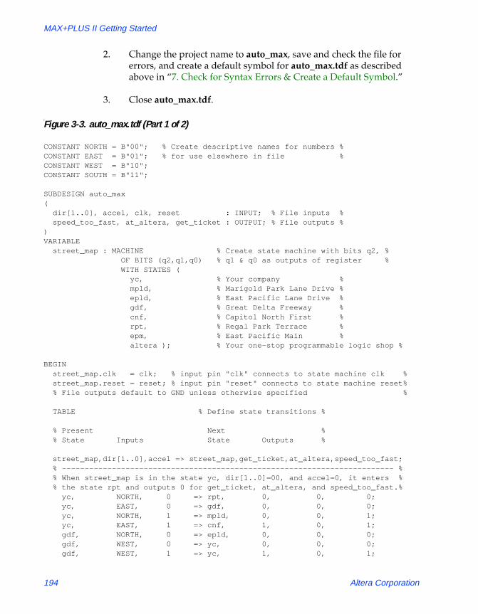
Figure 3-3. auto_max.tdf (Part 1 of 2)
CONSTANT NORTH = B"00"; % Create descriptive names for numbers %CONSTANT EAST = B"01"; % for use elsewhere in file %CONSTANT WEST = B"10";CONSTANT SOUTH = B"11";
SUBDESIGN auto_max( dir[1..0], accel, clk, reset : INPUT; % File inputs % speed_too_fast, at_altera, get_ticket : OUTPUT; % File outputs %)VARIABLE street_map : MACHINE % Create state machine with bits q2, % OF BITS (q2,q1,q0) % q1 & q0 as outputs of register % WITH STATES ( yc, % Your company % mpld, % Marigold Park Lane Drive % epld, % East Pacific Lane Drive % gdf, % Great Delta Freeway % cnf, % Capitol North First % rpt, % Regal Park Terrace % epm, % East Pacific Main % altera ); % Your one-stop programmable logic shop %
BEGIN street_map.clk = clk; % input pin "clk" connects to state machine clk % street_map.reset = reset; % input pin "reset" connects to state machine reset% % File outputs default to GND unless otherwise specified %
TABLE % Define state transitions %
% Present Next % % State Inputs State Outputs %
street_map,dir[1..0],accel => street_map,get_ticket,at_altera,speed_too_fast; % ------------------------------------------------------------------------- % % When street_map is in the state yc, dir[1..0]=00, and accel=0, it enters % % the state rpt and outputs 0 for get_ticket, at_altera, and speed_too_fast.% yc, NORTH, 0 => rpt, 0, 0, 0; yc, EAST, 0 => gdf, 0, 0, 0; yc, NORTH, 1 => mpld, 0, 0, 1; yc, EAST, 1 => cnf, 1, 0, 1; gdf, NORTH, 0 => epld, 0, 0, 0; gdf, WEST, 0 => yc, 0, 0, 0; gdf, WEST, 1 => yc, 1, 0, 1;
194 Altera Corporation

Section 3: MAX+PLUS II Tutorial
81_GSBOOK.fm5 Page 195 Tuesday, October 14, 1997 4:04 PM
gdf, EAST, 0 => cnf, 0, 0, 0; gdf, EAST, 1 => cnf, 1, 0, 1; gdf, NORTH, 1 => mpld, 0, 0, 0; cnf, NORTH, 0 => epm, 0, 0, 0; cnf, WEST, 0 => gdf, 0, 0, 0; cnf, NORTH, 1 => altera, 0, 0, 1; cnf, WEST, 1 => yc, 1, 0, 1; rpt, NORTH, 0 => mpld, 0, 0, 0; rpt, NORTH, 1 => mpld, 0, 0, 1; rpt, EAST, 0 => epld, 0, 0, 0; rpt, EAST, 1 => epm, 0, 0, 1; rpt, SOUTH, 0 => yc, 0, 0, 0; epld, NORTH, X => mpld, 0, 0, 0; epld, WEST, 0 => rpt, 0, 0, 0; epld, WEST, 1 => rpt, 0, 0, 1; epld, SOUTH, X => gdf, 0, 0, 0; epld, EAST, 0 => epm, 0, 0, 0; epld, EAST, 1 => epm, 0, 0, 1; epm, NORTH, 0 => altera, 0, 0, 0; epm, NORTH, 1 => altera, 0, 0, 1; epm, SOUTH, 0 => cnf, 0, 0, 0; epm, SOUTH, 1 => cnf, 0, 0, 1; epm, WEST, 0 => epld, 0, 0, 0; epm, WEST, 1 => rpt, 0, 0, 1; mpld, WEST, 0 => rpt, 0, 0, 0; mpld, SOUTH, 0 => epld, 0, 0, 0; mpld, WEST, 1 => yc, 0, 0, 1; mpld, SOUTH, 1 => gdf, 0, 0, 0; altera, X, X => altera, 0, 1, 0;
END TABLE;END;
Figure 3-3. auto_max.tdf (Part 2 of 2)
Altera Corporation 195

MAX+PLUS II Getting Started
81_GSBOOK.fm5 Page 196 Tuesday, October 14, 1997 4:04 PM
Session 4: Create a Waveform Design File
In this session, you will use the MAX+PLUS II Waveform Editor to enter and save a Waveform Design File (.wdf) called speed_ch.wdf. It includes the speed state machine, which contains the states legal, warning, and ticket. The speed_ch.wdf file checks whether or not your vehicle is traveling at a legal speed. The first time your car exceeds the speed limit, you are given a warning; the second time you speed, you get a speeding ticket. This session includes the following steps:
1. Create a new file and specify the project name.2. Create input, output, and buried nodes.3. Set the grid size and show the grid.4. Edit the buried state machine node waveform.5. Edit the input and output node waveforms.6. Confirm the edits.7. Check for basic errors and create a default symbol.
1 If you have not purchased the waveform design entry feature for MAX+PLUS II, you can use an AHDL TDF version of the speed_ch.wdf file, called speed_ch.tdf. This file is available in the \max2work\chiptrip subdirectory. Copy this file into your \tutorial subdirectory and proceed to Ò7. Check for Basic Errors & Create a Default SymbolÓ on page 209.
f Go to ÒCreating a Waveform Design FileÓ using Search for Help on (Help menu).
196 Altera Corporation

Section 3: MAX+PLUS II Tutorial
81_GSBOOK.fm5 Page 197 Tuesday, October 14, 1997 4:04 PM
1. Create a New File & Specify the Project Name
In this step, you will create a new WDF called speed_ch.wdf and name the project.
To create a new file and specify the project name:
1. Choose New (File menu), select Waveform Editor file, select the .wdf extension in the drop-down list box, and choose OK to open an untitled Waveform Editor window. You must create the file with the .wdf extension to take advantage of design entry features in the Waveform Editor.
2. If necessary, maximize the Waveform Editor window by clicking Button 1 on the Maximize button in the title bar.
3. Choose Save As (File menu). Type speed_ch.wdf in the File Name box.
4. Make sure that \max2work\tutorial appears as the current directory in the Directory is field. Choose OK to save the speed_ch.wdf file.
5. Choose Project Set Project to Current File or Project Name (File menu) and change the project name to speed_ch (see Ò2. Specify the Project NameÓ on page 170).
Altera Corporation 197

MAX+PLUS II Getting Started
81_GSBOOK.fm5 Page 198 Tuesday, October 14, 1997 4:04 PM
See the following illustration:
2. Create Input, Output & Buried Nodes
You create a WDF by entering input node waveforms and the desired output node waveforms. You can also create optional buried node waveforms to provide logical links between inputs and outputs.
You will create three input nodes for speed_ch.wdf: accel_in, reset, and clk. The accel_in node represents your acceleration. When your car speeds up, the waveformÕs logic level changes from low (0) to high (1); when you slow down, the signal returns to low. The reset and clk nodes provide secondary inputs, i.e., Reset (Clear) and Clock inputs, to the registers that will be created to implement your buried and output nodes.
You will also create a buried node called speed that represents a state machine. This state machine informs you about possible states resulting from your level of speed.
Node/group information area. Double-clicking Button 1 in a blank space in this area automatically opens the Insert Node dialog box.
Zoom Out button
Overwrite Low (0) button
Overwrite Undefined (X) button
Overwrite Invert button
Overwrite Count Value button
Overwrite High (1) button
Overwrite Clock button
Overwrite High Impedance (Z) button
Overwrite Group Value button
Selection tool
Text tool
Waveform Editing tool
Zoom In button
Fit in Window button
Overwrite State Name button
198 Altera Corporation

Section 3: MAX+PLUS II Tutorial
81_GSBOOK.fm5 Page 199 Tuesday, October 14, 1997 4:04 PM
Finally, you will create the get_ticket node that defines the output expected from your specified combination of inputs.
To create the nodes:
1. Click Button 1 in the topmost blank space in the node/group information area, as shown in the illustration on page 198, and choose Insert Node (Node menu). The Insert Node dialog box is displayed:
2. Type accel_in in the Node Name box.
3. Select 0 in the Default Value drop-down list box.
4. Select Input Pin under I/O Type.
5. In the bottom half of the dialog box, select Pin Input under Node Type.
6. Choose OK. The new node appears in the topmost blank space in the window.
7. Repeat steps 1 through 6 to create the reset and clk input nodes.
f Press F1 when the Insert Node dialog box is displayed to get help on the dialog box.
Specifies the node name.
Specifies an initial logic level of 0, 1, X, or Z for a node, or an initial state name for a state machine node.
Specifies Clock, Reset (i.e., Clear), and Preset inputs to a registered or state machine node.
Specifies the type of logic that drives the node.
Specifies the I/O type of the node.
Altera Corporation 199

MAX+PLUS II Getting Started
81_GSBOOK.fm5 Page 200 Tuesday, October 14, 1997 4:04 PM
8. Repeat steps 1 through 7 to create the two output nodes speed and get_ticket with the following characteristics:
The new nodes appear as shown in the following illustration:
1 To display more or less of the waveform drawing area, resize the Name, Type, and/or Value fields by pressing Button 1 on each resizing handle and dragging it to the left or right.
f Go to ÒBuried Nodes,Ó ÒInput Nodes,Ó and/or ÒOutput NodesÓ using Search for Help on (Help menu).
NodeName:
Default Value:
I/OType:
Node Type:
Secondary Inputs:
speed X Buried Node Machine Reset=resetClock=clk
get_ticket 0 Output Pin Registered Clock=clk
Waveform drawing area
Node handle shows the I/O type of the node.
Name field
Type field shows the logic that drives the node. Appears in WDFs only.
Value field
Field resizing handles
Zoom In button
Zoom Out button
200 Altera Corporation

Section 3: MAX+PLUS II Tutorial
81_GSBOOK.fm5 Page 201 Tuesday, October 14, 1997 4:04 PM
3. Set the Grid Size & Show the Grid
To prepare for waveform editing, you will set the grid size and display the grid:
1. Choose Grid Size (Options menu). The Grid Size dialog box is displayed.
2. Type 30ns to set the grid at 30 nanosecond intervals. The time unit must immediately follow the time value (i.e., with no space in between).
3. Choose OK.
1 In a WDF, the grid size is arbitrary: the time scale indicates only a sequential order of operation, not a specific response time. A specific grid size is used in this tutorial session solely to provide tutorial steps that are easy to follow.
4. If necessary, turn on Show Grid (Options menu) to display the dashed vertical grid lines in the window.
1 In a WDF, Snap to Grid (Options menu) is always turned on to enable the ÒmagneticÓ properties of the grid.
4. Edit the Buried State Machine Node Waveform
To edit the waveform of the buried state machine node speed, you will enter three state names on the waveform to represent the transitions between the legal, warning, and ticket states.
1 As you edit your waveforms, you can change the window display to view larger or smaller portions of the file by clicking Button 1 on the Zoom In, Zoom Out, and Fit in Window buttons on the tool palette, as shown in the illustration on page 198.
To edit the speed node:
1. Click Button 1 in the Value field of the speed node to select the entire waveform.
Altera Corporation 201

MAX+PLUS II Getting Started
81_GSBOOK.fm5 Page 202 Tuesday, October 14, 1997 4:04 PM
2. Choose the Overwrite State Name command (Edit menu) or the Overwrite State Name button on the tool palette, as shown in the illustration on page 198.
3. Type legal in the State Name box.
4. Choose OK. The entire waveform is overwritten with the state name legal.
5. If necessary, scroll or zoom out to display the grid line at 300 ns.
See the following illustration:
6. Click Button 1 on the Waveform Editing tool in the tool palette on the left side of the window, as shown in the illustration on page 198, to select it. The Selection pointer changes into the Waveform Editing pointer.
Reference field displays time at current Reference cursor location. Changes to End field during waveform selection.
Time field displays time at current mouse pointer location. Changes to Start field during waveform selection.
Reference cursor handle
202 Altera Corporation

Section 3: MAX+PLUS II Tutorial
81_GSBOOK.fm5 Page 203 Tuesday, October 14, 1997 4:04 PM
7. Zoom in or out or scroll the window to display the interval from 300 to 540 ns. If you drag to the edge of the window, the file scrolls automatically.
8. Refer to the Time field to find your exact mouse pointer location. With the Waveform Editing pointer, press Button 1 at 300 ns on the speed node, and drag the mouse until the interval from 300 to 540 ns is selected. If you drag to the edge of the window, the file scrolls automatically.
1 As you drag the mouse to select a waveform interval, the Time and Reference fields turn into Start and End fields that show the size of the selected interval.
9. Release Button 1. The Overwrite State Name dialog box opens automatically because you used the Waveform Editing tool on a state machine waveform.
10. Type warning in the State Name box.
11. Choose OK. The selected interval is overwritten with the state name warning.
12. Repeat steps 7 through 11 to overwrite the interval 540 to 660 ns with the state name ticket.
Altera Corporation 203

MAX+PLUS II Getting Started
81_GSBOOK.fm5 Page 204 Tuesday, October 14, 1997 4:04 PM
The speed node waveform appears as shown in the following illustration (displayed after choosing the Fit in Window button from the tool palette to show the full length of each waveform):
5. Edit the Input & Output Node Waveforms
You will now edit the input and output node waveforms. On the accel_in waveform, you will overwrite two high logic level intervals (to represent your carÕs acceleration beyond legal speeds) as the speed state machine changes first from legal to warning, and then from warning to ticket. You will also overwrite an undefined (X) logic level interval on accel_in to mark the transition from the ticket state to the legal state.
You will overwrite the clk signal with a high logic level at alternate 60-ns intervals. You will not change the reset signal.
You will edit the get_ticket output node by overwriting a high logic level interval on its waveform that corresponds to the ticket interval on the speed state machine waveform.
Fit in Window button
Overwrite Undefined (X) button
204 Altera Corporation

Section 3: MAX+PLUS II Tutorial
81_GSBOOK.fm5 Page 205 Tuesday, October 14, 1997 4:04 PM
To edit the nodes:
1. If necessary, scroll or zoom out to display the 270-ns grid line.
2. With the Waveform Editing tool, press Button 1 at 270 ns on the accel_in waveform, drag the mouse until the interval from 270 to 330 ns (i.e., two grid units) is selected, then release Button 1.
The selected interval is overwritten with a high logic level, which is the complement of the original low logic level. The high logic interval corresponds to the speed state machine transition from a legal to warning state (i.e., if speed is in the state legal and accel_in goes high, then speed goes into state warning).
1 The Waveform Editing tool overwrites an interval on a low or high waveform with its logic level complement. The complement is defined as the opposite of the logic level at the beginning of the interval. High-impedance (Z) and undefined (X) waveforms are also overwritten with low logic levels.
3. Repeat steps 1 and 2 to overwrite a high logic level on the interval from 510 to 570 ns (two grid units) on the accel_in waveform, which corresponds to the state machine transition from warning to ticket (i.e., if speed is in the state warning and accel_in goes high, then speed goes into state ticket).
4. If necessary, scroll or zoom out to display the 630-ns grid line.
5. Click Button 1 on the Selection tool on the tool palette to activate the Selection pointer. The state machine interval is automatically deselected, and the Reference cursor moves to the beginning of the interval.
SHORTCUTS Pressing the Esc key changes the current tool into the Selection tool.
The time at the cursor location is displayed both at the top of the cursor and in the Reference field. The logic levels or state names at this location are shown in the Value field. A dash (-) may appear instead of a value in the Value field if the field is too narrow to display the logic level.
Altera Corporation 205
MAX+PLUS II Getting Started
81_GSBOOK.fm5 Page 206 Tuesday, October 14, 1997 4:04 PM
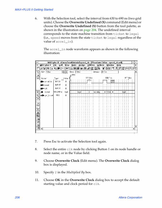
6. With the Selection tool, select the interval from 630 to 690 ns (two grid units). Choose the Overwrite Undefined (X) command (Edit menu) or choose the Overwrite Undefined (X) button from the tool palette, as shown in the illustration on page 204. The undefined interval corresponds to the state machine transition from ticket to legal (i.e., speed moves from the state ticket to legal regardless of the value of accel_in).
The accel_in node waveform appears as shown in the following illustration:
7. Press Esc to activate the Selection tool again.
8. Select the entire clk node by clicking Button 1 on its node handle or node name, or in the Value field.
9. Choose Overwrite Clock (Edit menu). The Overwrite Clock dialog box is displayed.
10. Specify 2 in the Multiplied By box.
11. Choose OK in the Overwrite Clock dialog box to accept the default starting value and clock period for clk.
206 Altera Corporation

Section 3: MAX+PLUS II Tutorial
81_GSBOOK.fm5 Page 207 Tuesday, October 14, 1997 4:04 PM
The clk node waveform appears as shown in the following illustration:
SHORTCUTS Shortcuts for opening the Overwrite Clock dialog box:
v Press Button 2 and choose Overwrite Clock from the pop-up menu.
or:
v Choose the Overwrite Clock button from the tool palette, as shown in the illustration above.
12. To edit the get_ticket node, repeat steps 1 through 3 on page 205 with the Waveform Editing tool to overwrite the interval from 540 to 660 ns on the get_ticket waveform with a high logic level. This high logic level corresponds to the ticket state on the speed nodeÕs waveform.
Overwrite Clock button
Altera Corporation 207

MAX+PLUS II Getting Started
81_GSBOOK.fm5 Page 208 Tuesday, October 14, 1997 4:04 PM
See the following illustration:
6. Confirm the Edits
To confirm your edits, you can move the Reference cursor to each successive logic level transition:
1. If necessary, press Esc to activate the Selection tool.
2. Click Button 1 at 0 ns in the waveform drawing area or drag the Reference cursor by its handle to move the cursor to the beginning of the file.
3. Press the . key or click Button 1 on the right cursor movement button next to the Reference field, as shown in the previous illustration, to move the Reference cursor to the next higher logic level transition. You can also choose Find Next Transition (Utilities menu).
Movement buttons for the Reference cursor
208 Altera Corporation

Section 3: MAX+PLUS II Tutorial
81_GSBOOK.fm5 Page 209 Tuesday, October 14, 1997 4:04 PM
4. Repeat as necessary to move the Reference cursor to each successive transition. The logic levels or state names at each transition are displayed in the Value field.
1 A dash (-) may appear instead of a value in the Value field if the field is too narrow to display the logic level.
f Choose h from the toolbar and click Button 1 on the Reference cursor handle.
7. Check for Basic Errors & Create a Default Symbol
You will now check the file for syntax errors to ensure that it was entered correctly, and then create a default symbol for use in the top-level GDF.
1. Choose Project Save & Check (File menu). See Ò11. Save the File & Check for Basic ErrorsÓ on page 183.
2. If Project Save & Check is successful, double-click Button 1 on the Document Control Menu box to close the Compiler window.
3. Make sure the speed_ch.wdf (or speed_ch.tdf) file is displayed in the active window, choose Create Default Symbol (File menu), and choose OK if you are asked whether it is OK to overwrite the existing Symbol File (.sym).
4. Double-click Button 1 on the document icon (or box) to close the file.
Altera Corporation 209

MAX+PLUS II Getting Started
81_GSBOOK.fm5 Page 210 Tuesday, October 14, 1997 4:04 PM
Session 5: Create the Top-Level Graphic Design File
In this session, you will use the MAX+PLUS II Graphic Editor to create the top-level design file for the chiptrip project. The chiptrip.gdf file incorporates the symbols that represent the four lower-level files, tick_cnt.gdf, auto_max.tdf, time_cnt.tdf, and speed_ch.wdf (or speed_ch.tdf), created in previous tutorial sessions.
Figure 3-4 shows the chiptrip.gdf file, which you will create by following the steps outlined below. This session also introduces additional command shortcuts to help you enter chiptrip.gdf quickly. For details about each step, see the procedures described in ÒSession 2: Create a Graphic Design File.Ó
1 Some buttons at the right end of the toolbar may be unavailable if your monitor is set to VGA display mode. All toolbar buttons and drop-down lists are available in larger screen displays. If you wish, you can switch to an alternate combination of toolbar buttons for VGA displays. Go to ÒSetting MAX+PLUS II PreferencesÓ using Search for Help on (Help menu) for instructions.
Figure 3-4. chiptrip.gdf
GLOBAL
ENABLE
CLK
TIME [7..0]
time_cnt
ACCEL_IN
RESET
CLK
GET_TICKET
speed_ch
GET_TICKET1
GET_TICKET2
CLK
TICKET [3..0]
tick_cnt
DIR [1..0]
ACCEL
CLK
RESET
SPEED_TOO_FAST
AT_ALTERA
GET_TICKET
auto_max
dir [1..0]
accel
clock
reset
enable time [7..0]
at_altera
ticket [3..0]
get_ticket1get_ticket2
at_alteraat_altera
get_ticket1
get_ticket2Connection dot
210 Altera Corporation

Section 3: MAX+PLUS II Tutorial
81_GSBOOK.fm5 Page 211 Tuesday, October 14, 1997 4:04 PM
1 If you skipped the previous tutorial sessions and did not create the four lower-level design files, you can copy the design files and their corresponding Symbol Files from the \max2work\chiptrip subdirectory into your \max2work\tutorial subdirectory. (On a UNIX workstation, the max2work directory is a subdirectory of the /usr directory.)
To create chiptrip.gdf:
1. Create a new GDF and save it as chiptrip.gdf in the \max2work\tutorial directory.
2. Specify the project name as chiptrip.
SHORTCUTS Shortcuts for setting the project name:
v Choose the Project Set Project to Current File button from the toolbar at the top of the window.
or:
v Type Ctrl+Shift+J.
3. Enter the symbols for the schematic:
a. Use the Enter Symbol command (Symbol menu) to enter the symbols that represent the lower-level design files created in earlier tutorial sessions:
b. Enter a GLOBAL primitive.
c. Enter five INPUT pins and three OUTPUT pins.
Symbol Name: Design File: Tutorial Session:
tick_cnt tick_cnt.gdf Session 2auto_max auto_max.tdf Session 3time_cnt time_cnt.tdf Session 3speed_ch speed_ch.wdf Session 4
Altera Corporation 211

MAX+PLUS II Getting Started
81_GSBOOK.fm5 Page 212 Tuesday, October 14, 1997 4:04 PM
SHORTCUTS Shortcuts for opening the Enter Symbol dialog box:
v With the Selection tool, double-click Button 1 in a blank space.
or:
v With any palette tool, press Button 2 in a blank space and choose Enter Symbol from the pop-up menu.
4. Name the pins as follows:
SHORTCUTS Shortcuts for naming pins:
v With the Selection or Text tool, double-click Button 1 on the default pin name and type the desired pin name.
or:
v With any palette tool, press Button 2 on the pin symbol, choose Edit Pin Name from the pop-up menu, and type the pin name.
1 If you press 9 after you edit a pin name, the next pin name below it is automatically selected for editing.
5. Draw node and bus lines to connect the symbols, as shown in Figure 3-4 on page 210. Be sure to draw all node lines, even those that do not connect symbols together graphically.
SHORTCUTS Node and bus lines have different line styles. As an alternative to using the Line Style command (Options menu), you can select a line style with the Line Style drop-down list box on the toolbar or with the Button 2 pop-up menu:
Input Pin Names: Output Pin Names:
dir[1..0] time[7..0]accel at_alteraclock ticket[3..0]resetenable
212 Altera Corporation

Section 3: MAX+PLUS II Tutorial
81_GSBOOK.fm5 Page 213 Tuesday, October 14, 1997 4:04 PM
v Click Button 1 on the Line Style drop-down list box ÒarrowÓ and choose the solid line style, which appears at the top of the list:
or:
v With any palette tool, press Button 2 on a node or bus line and choose the desired line style from the Line Style submenu.
6. To enter connection dots:
a. With the Selection tool or any drawing tool, click Button 1 on the intersection of two nodes to define an insertion point.
b. Choose Toggle Connection Dot (Edit menu).
SHORTCUTS Shortcuts for entering (or deleting) a connection dot:
v With the Selection tool or any drawing tool, double-click Button 1 on the intersection of two nodes.
or:
v With any palette tool, press Button 2 at the intersection of two nodes and choose Toggle Connection Dot from the pop-up menu.
or:
v With the any palette tool, click Button 1 on the intersection of two nodes and choose the Toggle Connection Dot button from the tool palette.
7. Assign names to the unconnected nodes to connect them by name, as shown in the following list and in Figure 3-4.
Altera Corporation 213

MAX+PLUS II Getting Started
81_GSBOOK.fm5 Page 214 Tuesday, October 14, 1997 4:04 PM
1 Symbols are identified here as <symbol name>:<symbol ID>. Your own symbol ID numbers will vary if you entered the symbols in a different order.
1 Pinstub names are always shown in capital letters in symbols generated with the Create Default Symbol command (File menu).
SHORTCUTS Shortcuts for naming nodes and buses:
v With any palette tool, click Button 1 on the node or bus line to deÞne an insertion point and type the desired name.
or:
v With any palette tool, press Button 2 on a node or bus line, choose Edit Node/Bus Name from the pop-up menu, and type the name.
or:
v With the Text tool, type a name on a node or bus line, or type a name in a blank space, then use the Selection pointer to drag the name onto a line to associate the name with the line.
Symbol: Pinstub/Pin Name: Node Name:
auto_max:1 AT_ALTERA at_alteraauto_max:1 GET_TICKET get_ticket1
at_altera (output pin) at_altera at_alteraspeed_ch:2 GET_TICKET get_ticket2tick_cnt:3 GET_TICKET1 get_ticket1tick_cnt:3 GET_TICKET2 get_ticket2
214 Altera Corporation

Section 3: MAX+PLUS II Tutorial
81_GSBOOK.fm5 Page 215 Tuesday, October 14, 1997 4:04 PM
SHORTCUTS You may wish to customize some or all of your text blocks. As an alternative to using the Text Size and Font commands (Options menu), you can specify the text size and font with the drop-down list boxes on the toolbar or with the Button 2 pop-up menu.
v Click Button 1 on the drop-down list box ÒarrowsÓ to display the lists of available fonts and sizes, and chose the desired text size or font:
or:
v With any palette tool, press Button 2 on a selected node or bus name and choose the desired text size or font from the Text Size or Font submenus.
8. Choose Save (File menu) to save the file.
f For a list of additional command shortcuts for the Graphic Editor, go to ÒGraphic & Symbol Editor ShortcutsÓ and/or the names of the various commands using Search for Help on (Help menu).
Altera Corporation 215

MAX+PLUS II Getting Started
81_GSBOOK.fm5 Page 216 Tuesday, October 14, 1997 4:04 PM
Session 6: Compile the Project
In this session, you will compile the chiptrip project. The MAX+PLUS II Compiler checks the project for errors, synthesizes the logic, fits the project into an Altera device, generates output files for simulation and programming, and updates the Hierarchy Display window. This session includes the following steps:
1. Open the Compiler window.2. Select a device family.3. Turn on the Smart Recompile command.4. Turn on the Design Doctor utility.5. Turn on the Security Bit.6. Select a global project logic synthesis style.7. Turn on the Timing SNF Extractor.8. Specify Report File sections to generate.9. Run the Compiler.10. Locate the source of a message.11. Get help on a message.12. View the Report File.
1 If you did not complete the earlier tutorial sessions to create the design files for the chiptrip projectÑtick_cnt.gdf, time_cnt.tdf, auto_max.tdf, speed_ch.wdf, and chiptrip.gdfÑyou can copy the design files and their corresponding Symbol Files from the \max2work\chiptrip subdirectory into the \max2work\tutorial subdirectory. (On a UNIX workstation, the max2work directory is a subdirectory of thee /usr directory.) You must then specify chiptrip as the project name. See Ò2. Specify the Project NameÓ on page 170.
216 Altera Corporation
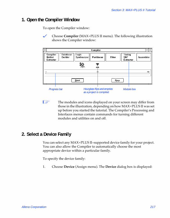
Section 3: MAX+PLUS II Tutorial
81_GSBOOK.fm5 Page 217 Tuesday, October 14, 1997 4:04 PM
1. Open the Compiler Window
To open the Compiler window:
v Choose Compiler (MAX+PLUS II menu). The following illustration shows the Compiler window:
1 The modules and icons displayed on your screen may differ from those in the illustration, depending on how MAX+PLUS II was set up before you started the tutorial. The CompilerÕs Processing and Interfaces menus contain commands for turning different modules and utilities on and off.
2. Select a Device Family
You can select any MAX+PLUS IIÐsupported device family for your project. You can also allow the Compiler to automatically choose the most appropriate device within a particular family.
To specify the device family:
1. Choose Device (Assign menu). The Device dialog box is displayed:
Module boxProgress bar Hourglass flips and empties as a project is compiled.
Altera Corporation 217

MAX+PLUS II Getting Started
81_GSBOOK.fm5 Page 218 Tuesday, October 14, 1997 4:04 PM
2. If the MAX 7000 family is not already selected, select MAX7000 in the Device Family drop-down list box.
3. If necessary, select AUTO in the Devices box.
4. Choose OK.
3. Turn on the Smart Recompile Command
When the ÒsmartÓ recompile feature is turned on, the Compiler saves extra database information for the current project for use in subsequent compilations. During ÒsmartÓ recompilation, the Compiler can determine which modules are not needed to recompile the project, and skip them during recompilation, thereby reducing compilation time.
In ÒSession 8: View the Fit in the Floorplan EditorÓ on page 231, you will recompile the chiptrip project after changing a pin assignment. Turning on the Smart Recompile command now will speed things up when you go through the steps in Session 8.
To turn on the smart recompile feature:
v Choose Smart Recompile (Processing menu).
218 Altera Corporation

Section 3: MAX+PLUS II Tutorial
81_GSBOOK.fm5 Page 219 Tuesday, October 14, 1997 4:04 PM
4. Turn on the Design Doctor Utility
During compilation, the optional Design Doctor utility checks all design files in a project for logic that may cause reliability problems in a programmed device.
1 If you have not purchased the Design Doctor utility for MAX+PLUS II, skip to Ò5. Turn on the Security BitÓ on page 220.
To turn on the Design Doctor utility and specify a set of design rules for the analysis:
1. Choose Design Doctor (Processing menu). When the command is turned on, a checkmark appears next to the command name on the menu and the Design Doctor icon appears in the Compiler window below the Logic Synthesizer module box, as shown in the following illustration:
2. Choose Design Doctor Settings (Processing menu). The Design Doctor Settings dialog box is displayed:
Design Doctor icon
Altera Corporation 219
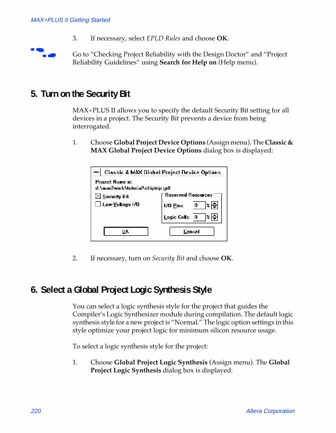
MAX+PLUS II Getting Started
81_GSBOOK.fm5 Page 220 Tuesday, October 14, 1997 4:04 PM
3. If necessary, select EPLD Rules and choose OK.
f Go to ÒChecking Project Reliability with the Design DoctorÓ and ÒProject Reliability GuidelinesÓ using Search for Help on (Help menu).
5. Turn on the Security Bit
MAX+PLUS II allows you to specify the default Security Bit setting for all devices in a project. The Security Bit prevents a device from being interrogated.
1. Choose Global Project Device Options (Assign menu). The Classic & MAX Global Project Device Options dialog box is displayed:
2. If necessary, turn on Security Bit and choose OK.
6. Select a Global Project Logic Synthesis Style
You can select a logic synthesis style for the project that guides the CompilerÕs Logic Synthesizer module during compilation. The default logic synthesis style for a new project is ÒNormal.Ó The logic option settings in this style optimize your project logic for minimum silicon resource usage.
To select a logic synthesis style for the project:
1. Choose Global Project Logic Synthesis (Assign menu). The Global Project Logic Synthesis dialog box is displayed:
220 Altera Corporation

Section 3: MAX+PLUS II Tutorial
81_GSBOOK.fm5 Page 221 Tuesday, October 14, 1997 4:04 PM
2. If necessary, select Normal in the Global Project Synthesis Style drop-down list box and choose OK.
f Go to ÒSpecifying Global Project Logic Synthesis SettingsÓ using Search for Help on (Help menu).
Altera Corporation 221

MAX+PLUS II Getting Started
81_GSBOOK.fm5 Page 222 Tuesday, October 14, 1997 4:04 PM
7. Turn on the Timing SNF Extractor
The Compiler can create a Simulator Netlist File (.snf) that contains the logic and timing information used by the MAX+PLUS II Simulator and Timing Analyzer. A timing SNF is a binary file that contains all logic and timing information required for simulation, delay prediction, and timing analysis.
To turn on the Timing SNF Extractor module:
v Choose Timing SNF Extractor (Processing menu). When the command is turned on, a checkmark appears next to the command name on the menu and the Timing SNF Extractor module box appears in the Compiler window, as shown in the following illustration:
1 If the module boxes for the EDIF, VHDL, and/or Verilog Netlist Writer are displayed, turn these modules off with the EDIF Netlist Writer, VHDL Netlist Writer, and/or Verilog Netlist Writer commands (Interfaces menu).
8. Specify Report File Sections to Generate
The Report File (.rpt), which is generated by the CompilerÕs Fitter module, shows how device resources are used in the chiptrip project. The Compiler allows you to specify which optional information should be included in a Report File.
Timing SNF Extractor module box
222 Altera Corporation

Section 3: MAX+PLUS II Tutorial
81_GSBOOK.fm5 Page 223 Tuesday, October 14, 1997 4:04 PM
To specify that all sections should be included in the Report File:
1. Choose Report File Settings (Processing menu). The Report File Settings dialog box is displayed:
2. If necessary, turn All on and choose OK.
f Go to ÒReport File FormatÓ using Search for Help on (Help menu).
9. Run the Compiler
To compile the project:
1. Choose the Start button. As the Compiler processes the chiptrip project, any information, error, or warning messages appear in a Message Processor window that opens automatically.
Altera Corporation 223

MAX+PLUS II Getting Started
81_GSBOOK.fm5 Page 224 Tuesday, October 14, 1997 4:04 PM
The Stop/Show Status button appears in place of the Stop button when the CompilerÕs Partitioner and Fitter modules are processing the project, as shown in the following illustration:
2. While the Fitter module is processing the project, choose the Stop/Show Status button in the Compiler window. The Partitioner/Fitter Status dialog box is displayed, listing all chips in the project and their fitting status:
3. Choose the Continue Compilation button in the Partitioner/Fitter Status dialog box to resume compilation.
The Compiler runs in the background, freeing your computer for other work. However, this compilation is short and you will not have to wait long for it to finish. When you compile a larger, more complex project, you can start a compilation and then switch to another application to continue your work.
The Compiler’s Fitter module is currently processing the project.
Stop/Show Status button
224 Altera Corporation

Section 3: MAX+PLUS II Tutorial
81_GSBOOK.fm5 Page 225 Tuesday, October 14, 1997 4:04 PM
When compilation is finished, icons representing the output files generated by the Compiler appear below the module boxes. You can open any of these output files by double-clicking Button 1 on the appropriate file icon. The chiptrip compilation processing also generates four information messages, as shown in the following illustration:
As shown in the illustration, the Design Doctor has given the chiptrip project a Òclean bill of health,Ó and the Compiler has selected the EPM7032LC44-6 device (an EPM7032-6 device in a 44-pin plastic J-lead chip carrier package) for the project.
Message Processor window
Automatically highlights the source of an error or warning. If a message has multiple sources, you can locate each source in succession.
Allows you to scroll through all messages. The total number of messages generated and the number of the currently selected message are displayed.
Displays information about the cause of the message and how to correct it.
Allows you to trace the source(s) of a message in the Floorplan Editor instead of a design or ancillary file.
Opens the Floorplan Editor and highlights all source(s) of the selected message simultaneously.
Report File icon
Altera Corporation 225

MAX+PLUS II Getting Started
81_GSBOOK.fm5 Page 226 Tuesday, October 14, 1997 4:04 PM
10. Locate the Source of a Message
You can direct the Message Processor to locate the source of a message within the relevant design file.
To locate the source of a message:
1. If necessary, switch to the Message Processor window by choosing Message Processor (MAX+PLUS II menu).
2. Click Button 1 on the first message or on the right side of the Message button to select the first message: Info: State 'altera' in the state machine '|auto_max:1|street_map' is never exited.
3. If necessary, turn off the Locate in Floorplan Editor option.
4. Choose the Locate button.
SHORTCUTS Double-clicking Button 1 on a message is a shortcut for choosing the Locate button.
The Message Processor automatically opens the TDF containing the source of the message, and highlights the sourceÕs location within the design file, as shown in the following illustration:
Source of the message is highlighted in the original design file.
226 Altera Corporation

Section 3: MAX+PLUS II Tutorial
81_GSBOOK.fm5 Page 227 Tuesday, October 14, 1997 4:04 PM
5. If the message has multiple sources, you can locate the additional sources by choosing Locate again.
6. Once you finish viewing the design file(s), close the design editor window(s) to return to the Message Processor window.
11. Get Help on a Message
You can get instant context-sensitive help on the cause of a message.
To get help on a message:
1. Select a message.
2. Choose the Help on Message button in the Message Processor window.
The Message Processor opens the MAX+PLUS II Help window, which shows the cause of the message and any action you must take to correct the problem.
The following illustration shows the Help topic for the first message in the Message Processor window:
3. Once you finish viewing the Help topic, close the Help window and return to the Compiler window.
Altera Corporation 227

MAX+PLUS II Getting Started
81_GSBOOK.fm5 Page 228 Tuesday, October 14, 1997 4:04 PM
12. View the Report File
The Report File (.rpt) contains two types of information about the chiptrip project: project-wide information (sections entitled Device Summary, Project Compilation Messages, File Hierarchy, etc.) and device-specific information (sections entitled Resource Usage, Routing Resources, Logic Cell Interconnections, etc.). You can open the Report File for the current compilation directly from the Compiler window.
To open the Report File:
1. Double-click Button 1 on the Report File icon in the Compiler window, as shown in the illustration on page 225. The Report File is displayed in a Text Editor window, as shown in the following illustration:
f Choose h on the toolbar and click on a section heading delimited by ** characters to go to context-sensitive help on specific sections of the Report File.
2. Once you finish viewing the Report File, close it to return to the Compiler window.
3. Close the Compiler window.
228 Altera Corporation
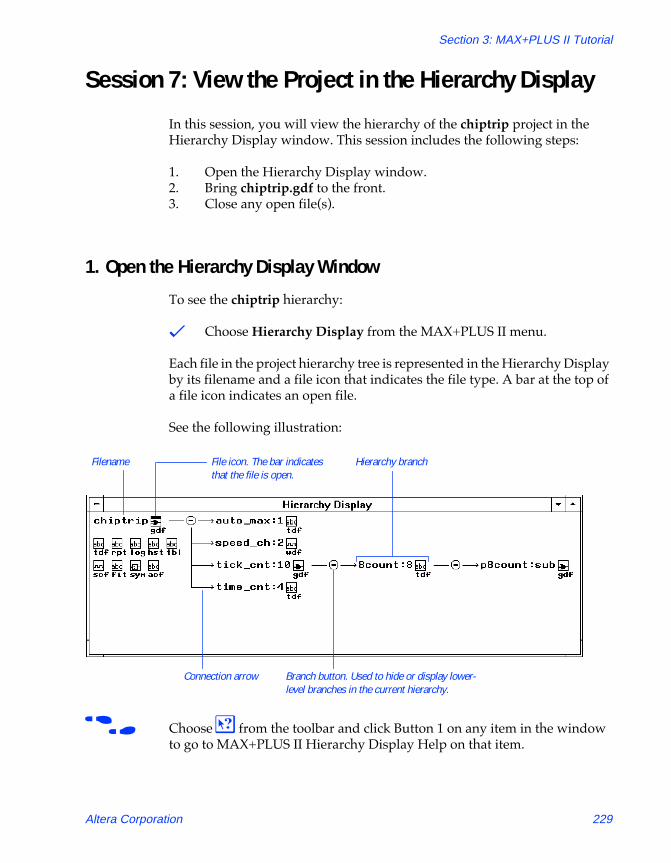
Section 3: MAX+PLUS II Tutorial
81_GSBOOK.fm5 Page 229 Tuesday, October 14, 1997 4:04 PM
Session 7: View the Project in the Hierarchy Display
In this session, you will view the hierarchy of the chiptrip project in the Hierarchy Display window. This session includes the following steps:
1. Open the Hierarchy Display window.2. Bring chiptrip.gdf to the front.3. Close any open file(s).
1. Open the Hierarchy Display Window
To see the chiptrip hierarchy:
v Choose Hierarchy Display from the MAX+PLUS II menu.
Each file in the project hierarchy tree is represented in the Hierarchy Display by its filename and a file icon that indicates the file type. A bar at the top of a file icon indicates an open file.
See the following illustration:
f Choose h from the toolbar and click Button 1 on any item in the window to go to MAX+PLUS II Hierarchy Display Help on that item.
Filename File icon. The bar indicates that the file is open.
Hierarchy branch
Connection arrow Branch button. Used to hide or display lower-level branches in the current hierarchy.
Altera Corporation 229

MAX+PLUS II Getting Started
81_GSBOOK.fm5 Page 230 Tuesday, October 14, 1997 4:04 PM
2. Bring chiptrip.gdf to the Front
The Hierarchy Display window allows you to quickly open or bring to the front any design file in the project hierarchy, or any ancillary file with the same filename as the project. When you open a file from the Hierarchy Display, MAX+PLUS II automatically opens the appropriate editor.
To bring chiptrip.gdf to the front:
v Double-click Button 1 on the GDF icon next to the chiptrip Þlename. The Graphic Editor window with chiptrip.gdf comes to the front.
f Go to ÒNavigating the HierarchyÓ using Search for Help on (Help menu).
3. Close any Open File(s)
To close any open files in the Hierarchy Display:
1. Bring the Hierarchy Display window back to the front. The chiptrip.gdf icon has a bar over it, indicating that the file is open.
2. Click Button 1 on the chiptrip.gdf icon to select it.
1 You can select multiple files by pressing the Shift key while clicking Button 1 on file icons.
3. Choose Close Editor (File menu). The chiptrip.gdf file is closed and the bar above its icon disappears.
4. Double-click Button 1 on the document icon (or box) to close the Hierarchy Display window.
f Go to ÒSelecting a File IconÓ using Search for Help on (Help menu).
230 Altera Corporation
Section 3: MAX+PLUS II Tutorial
81_GSBOOK.fm5 Page 231 Tuesday, October 14, 1997 4:04 PM
Session 8: View the Fit in the Floorplan Editor
In this session, you will use the Floorplan Editor window to view Compiler partitioning and fitting results, as well as to enter and edit physical device resource assignments for your project. You will also view the CompilerÕs logic placement, compare your own assignments to the CompilerÕs assignments, and back-annotate the results of compilation. This session includes the following steps:
1. Open the Floorplan Editor window.2. Back-annotate the project and edit assignments.3. Recompile the project.4. Display routing information in the Floorplan Editor window.5. Display equation and routing information with the Report File
Equation Viewer.
f Go to ÒFloorplan Editor ProceduresÓ using Search for Help on (Help menu) for more information on using the Floorplan Editor.
Altera Corporation 231

MAX+PLUS II Getting Started
81_GSBOOK.fm5 Page 232 Tuesday, October 14, 1997 4:04 PM
1. Open the Floorplan Editor Window
The Floorplan Editor provides two displaysÑthe Device View and the LAB View. The Device View shows all pins on a device package and their function. The LAB View shows the interior of the device, including all LABs; the individual logic cells within each LAB; and I/O cells, embedded cells, and Embedded Array Blocks (EABs) if they are available in the target device. (The EPM7032 device used in this project does not include I/O cells, embedded cells, or EABs.) The LAB View also displays pin locations so that you can see the relationships between pins and logic resources in the interior of the device.
To view chiptrip in the Floorplan Editor window:
1. Choose Floorplan Editor from the MAX+PLUS II menu. The Floorplan Editor opens and displays the view that was last used to examine the floorplan of the device selected for the project.
2. If necessary, click Button 1 on the Maximize button in the Floorplan Editor title bar to maximize the window.
3. If necessary, choose the LAB View and Last Compilation Floorplan commands from the Layout menu. The chiptrip project is displayed in the Floorplan Editor window, as shown in the following illustration:
232 Altera Corporation

Section 3: MAX+PLUS II Tutorial
81_GSBOOK.fm5 Page 233 Tuesday, October 14, 1997 4:04 PM
SHORTCUTS Double-clicking Button 1 in a blank space in the Floorplan Editor window switches back and forth between the LAB and Device View displays.
Clicking Button 1 on the Last Compilation Floorplan button on the tool palette is a shortcut for choosing the Last Compilation Floorplan command (Layout menu).
The color legend shows the colors used to identify unassigned and assigned pins, logic cells, and I/O cells.
The LAB View is currently displayed.
You can drag a node or pin name to the device to assign it to a pin, logic cell, LAB, chip, etc., depending on the selected view (all nodes and pins are currently assigned).
Zoom In buttonZoom Out button
Fit in Window button
Dedicated global pins are shown separately from LABs for some devices.
LAB Assignment Bin“Balloon text” displays information on the item at the current mouse pointer location.
Last Compilation Floorplan button
Current Assignments Floorplan button
Altera Corporation 233

MAX+PLUS II Getting Started
81_GSBOOK.fm5 Page 234 Tuesday, October 14, 1997 4:04 PM
2. Back-Annotate the Project & Edit Assignments
The Floorplan Editor allows you to view and edit your current assignments, which are stored in the projectÕs Assignment & Configuration File (.acf). After you have compiled the project, you can edit the CompilerÕs assignments, which are stored in the projectÕs Fit File (.fit), by back-annotating the project and then changing the current floorplan assignments.
To back-annotate your project:
1. Choose Back-Annotate Project (Assign menu). The Back-Annotate Project dialog box is displayed.
2. Turn on the Chips, Logic Cells, Pins & Devices option under Back-Annotate to ACF to back-annotate all assignments.
3. Choose OK. MAX+PLUS II copies the pin, logic cell, chip, and device assignments from the Fit File into the ACF, overwriting the previous assignments.
4. Choose Current Assignments Floorplan (Layout menu). The Floorplan Editor window displays the current assignments for the chiptrip project.
If some logic is unassigned in your project, the Floorplan Editor provides a list of unassigned node and pin names, as shown in the previous illustration. Each name has a ÒhandleÓ that you can drag to an individual pin or logic cellÑor to a more general assignment ÒbinÓÑin the Device View or LAB View display. You can also drag a node or pin with an existing assignment back to the list of unassigned nodes or to a different location on the device.
You can easily edit your current assignments in the Floorplan Editor window. In this example, you will reassign the clock pin to a new location and recompile the project.
To edit the clock pin assignment:
1. Choose Find Text (Utilities menu). The Find Text dialog box is displayed.
2. Type clock in the Search For box.
3. Turn off the All option under Types of Text to Find.
4. Turn on the Pin & Node Names option under Types of Text to Find.
234 Altera Corporation

Section 3: MAX+PLUS II Tutorial
81_GSBOOK.fm5 Page 235 Tuesday, October 14, 1997 4:04 PM
5. Choose OK. The clock pin assignment is highlighted and the information Òclock@43(Global CLK)Ó is displayed in the Selected Node(s) & Pin(s) field in the Floorplan Editor window.
1 On the EPM7032LC44 device, pin 43 is the dedicated global Clock pin. The Compiler automatically assigned the clock signal to this pin when the project was compiled in Session 7.
6. Turn on Show Moved Nodes in Gray (Options menu).
7. With Button 1, drag the selected clock pin assignment from pin 43 to an unassigned I/O pin of your choice. The assignment is shown in gray at its new location, as shown in the following illustration:
f Go to ÒBack-Annotating Assignments for a ProjectÓ and ÒFinding Nodes & Pins in the Floorplan EditorÓ using Search for Help on (Help menu) for more information on using the Floorplan Editor.
Reassigned Clock pin in a new location.
The assignment and location of a selected item are displayed in the Selected Node(s) & Pin(s) field.
Altera Corporation 235

MAX+PLUS II Getting Started
81_GSBOOK.fm5 Page 236 Tuesday, October 14, 1997 4:04 PM
3. Recompile the Project
Once you have edited the pin assignment for the clock input pin, you must recompile chiptrip to verify whether or not your new assignment is legal for the EPM7032LC44 device.
1. Open the Compiler window by choosing Compiler (MAX+PLUS II menu).
2. Choose Start. The Compiler begins processing the project, based on the new pin assignment. The Compiler then halts, informing you that the project doesnÕt fit, and asks if you wish to override some existing settings and/or assignments.
3. Choose Yes. The Override User Assignments dialog box appears, displaying the following message: Illegal assignment -- 'clock' on pin <number>.
4. Choose the Edit Pin Assignments & LCELLs button. The Edit Pin Assignments & LCELLs dialog box is displayed:
a. Click Button 1 on the clock assignment in the list box to select it, as shown in the following illustration:
b. Turn on the Ignore Pin Assignment option at the bottom of the dialog box.
236 Altera Corporation

Section 3: MAX+PLUS II Tutorial
81_GSBOOK.fm5 Page 237 Tuesday, October 14, 1997 4:04 PM
c. Choose OK to close the Edit Pin Assignments & LCELLs dialog box.
5. Choose OK to close the Override User Assignments dialog box. The Compiler continues processing the project and, when it finishes, displays a message indicating that project compilation was successful.
6. Choose Floorplan Editor (MAX+PLUS II menu) to return to the Floorplan Editor window.
7. Choose Last Compilation Floorplan (Layout menu). The clock pin assignment now reappears on pin 43.
8. Back-annotate the CompilerÕs assignments, as described in steps 2 through 4 on page 234.
4. Display Routing Information in the Floorplan Editor Window
The Floorplan Editor allows you to view the routing information for one or more selected logic cells, pins, and assignment bins using a variety of different methods. You can also view routing statistics for any part of the current chip.
To display node fan-in and fan-out routing information:
1. Turn on Show Node Fan-In and/or Show Node Fan-Out (Options menu).
SHORTCUTS Choose the Show Node Fan-In and Show Node Fan-Out buttons on the tool palette, as shown in the next illustration.
2. Go to the LAB View and select one or more logic cells, pins, or assignment bins.
Altera Corporation 237

MAX+PLUS II Getting Started
81_GSBOOK.fm5 Page 238 Tuesday, October 14, 1997 4:04 PM
The Floorplan Editor displays the fan-in (pink) and/or fan-out (blue) routing lines that apply to the selected item(s). The following illustration shows the fan-in and fan-out of the selected |speed_ch:2|speed~1 node at LC4 (logic cell 4):
Fan-in and fan-out lines are updated automatically when you move an assignment. In addition, if you move a node to a new location, the assignment color changes if the Show Moved Nodes in Gray command (Options menu) is turned on.
You can also choose to view only the signal paths between two or more items, without additional fan-in and fan-out information:
v Turn on Show Path (Options menu).
This command allows you to view only the connections between the selected nodes, and is especially useful for tracing critical timing paths. When Show Path is turned on, Show Node Fan-In and Show Node Fan-Out are turned off automatically, and vice versa.
SHORTCUTS Choose the Show Path button on the tool palette, as shown in the previous illustration.
Last Compilation Floorplan button
Show Path button
Show Node Fan-In button
Show Node Fan-Out button
Current Assignments Floorplan button
238 Altera Corporation

Section 3: MAX+PLUS II Tutorial
81_GSBOOK.fm5 Page 239 Tuesday, October 14, 1997 4:04 PM
To display detailed routing statistics for one or more logic cells, pins, or assignment bins:
1. Select one or more logic cells, pins, or assignment bins.
2. Choose Routing Statistics (Options menu), then choose the Calculate Most Congested Areas button. The Routing Statistics dialog box is displayed, as shown in the following illustration:
SHORTCUTS Double-clicking Button 1 on a single item is a shortcut for opening the Routing Statistics dialog box.
3. Choose OK to close the Routing Statistics dialog box.
Routing Statistics for the |speed_ch:2|speed~1 node are shown in this example.
Altera Corporation 239

MAX+PLUS II Getting Started
81_GSBOOK.fm5 Page 240 Tuesday, October 14, 1997 4:04 PM
5. Display Equation & Routing Information with the Report File Equation Viewer
The Floorplan Editor includes a Report File Equation Viewer that allows you to view the Report File (.rpt) equations, and fan-in and fan-out information for pin and logic cell assignments. You can view this information in two ways: by selecting individual assignments in the Floorplan Editor window; and by jumping to associated assignments within the Report File Equation Viewer window. This equation viewer allows you to examine the logic that feeds or is fed by any node in the project. As an example, you will view information for the time2 pin and then jump to the time0 pin using the Report File Equation Viewer.
To view the equation(s) for the time2 pin:
1. Choose Full Screen (Layout menu) to allow more room to display the chip.
2. Choose Report File Equation Viewer (Layout menu). The Report File Equation Viewer window appears at the bottom of the Floorplan Editor window.
3. Click Button 1 on the time2 pin in the Floorplan Editor window. The text time2@31(I/O) appears in balloon text when the mouse pointer is over the correct pin (pin 31).
1 Pin numbers may vary when you create the chiptrip project.
The equation and routing information for time2 appears in the Report File Equation Viewer window, as shown in the following illustration:
240 Altera Corporation

Section 3: MAX+PLUS II Tutorial
81_GSBOOK.fm5 Page 241 Tuesday, October 14, 1997 4:04 PM
1 If the Show Node Fan-In and Show Node Fan-Out commands (Options menu) are turned on, the Floorplan Editor displays the fan-in and fan-out lines that correspond to the items listed in the Report File Equation Viewer window.
4. While equation and routing information for the time2 pin is displayed in the Report File Equation Viewer window, select the ÒOUT: time0Ó pin under Fan-In with Button 1 and choose the < Go To button. The equation and routing information for the time0 pin then appears in the Report File Equation Viewer window. In addition, the time0 pin is highlighted in the Floorplan Editor window, and its fan-in and fan-out lines are displayed.
SHORTCUTS Double-clicking Button 1 on a node in the Fan-In or Fan-Out section of the Report File Equation Viewer window is a shortcut for selecting the node and choosing the Go To button.
f Go to ÒFloorplan Editor ProceduresÓ using Search for Help on (Help menu) for more information on working with the Floorplan Editor.
Nodes are labeled IN: (input pin), OUT: (output pin), BIDIR: (bidirectional pin), REG: (registered node), COMB: (combinatorial node), or MEM: (memory node).
The number shows how many nodes feed or are fed by the selected item.
time2 pin
Equations show the logic feeding the selected item(s).
Altera Corporation 241

MAX+PLUS II Getting Started
81_GSBOOK.fm5 Page 242 Tuesday, October 14, 1997 4:04 PM
Simulation Overview
Your logic circuit has compiled without errors. However, only a simulation will confirm that it behaves exactly as you desire. Skipping simulation is like buying a car without taking it for a test drive: you may be reasonably sure that it works, but does it actually fit your particular needs?
1 If you have not purchased the simulation tools for MAX+PLUS II, please proceed to ÒSession 12: Analyze TimingÓ on page 266.
What is Simulation?
Design entry and compilation are only part of the design process. Simulation is equally important, if not more so. Successful compilation only guarantees that a programming file will be created for your project, not that the project will perform as you expect. Yet, many designers avoid simulation because they think it is too slow, or too difficult to learn. Learning to simulate with MAX+PLUS II, however, is as easy as learning design entry and compilation. Since simulation provides the quickest, easiest way to verify your projectÕs performance, you can save both time and effort.
You simulate a project to verify that it functions correctly. Simulation allows you to thoroughly test your project to ensure that it responds correctly in every possible situation before you program it into a device.
During simulation, you supply input vectors to the MAX+PLUS II Simulator. The Simulator uses these inputs to create the output signals that a programmed device would produce under the same conditions. In a typical simulation session, you create multiple sets of input vectors to check the resulting outputs.
Depending on the kind of information you need, you can perform functional, timing, or linked multi-project simulation with MAX+PLUS II. Functional simulation tests only the logical operation of a project, while timing simulation tests both the logical operation and the worst-case timing of the target device(s). Linked simulation combines the functional and timing information from multiple projects to allow you to perform a board-level-type simulation. In this tutorial, you will perform a timing simulation.
242 Altera Corporation

Section 3: MAX+PLUS II Tutorial
81_GSBOOK.fm5 Page 243 Tuesday, October 14, 1997 4:04 PM
How Does the Chiptrip Simulation Work?
The chiptrip tutorial simulation sessions are set up as a driving simulation game. The inputs to chiptrip (e.g., direction, acceleration, Clock cycles) produce simulation outputs that correspond to intersections on the map in Figure 3-5. Thus, by creating the right inputs, you can determine the path you take as well as your speed.
Figure 3-5. Map to Altera
As in real life, there are rules for handling your car (the laws of physics) and for driving on each type of road (the laws of the state). Needless to say, there are also plenty of consequences if you break the rules.
You & Your Vehicle
Direction and acceleration are your main concerns. The directional inputs control the next location of your vehicle, based on its present location. For example, if you start at YC (Your Company) and travel one block east and one block north, you would drive past GDF to reach EPLD.
The acceleration input moves your car at one of two speeds in the direction you have chosen. When accel is low, you travel at normal speed, one block per Clock cycle (e.g., from YC to GDF). When accel is high, you accelerate through two blocks in a single Clock cycle (e.g., from YC to CNF).
YC
RPT
MPLD
EPLD
GDF CNF
EPM
Your Company
Residential Street: Normal speedonly; any acceleration results in aspeeding ticket.
Commercial Road: Acceleratingfor two Clock cycles results in aticket. Clock cycles can be non-consecutive.
Expressway: Any number ofaccelerations is allowed.
Altera Corporation 243

MAX+PLUS II Getting Started
81_GSBOOK.fm5 Page 244 Tuesday, October 14, 1997 4:04 PM
As you drive, the clock input ticks off the time units, and the enable input allows your time counter to count. By keeping enable high, you can time yourself and see how long it takes to get across town.
The Roads
You can travel along three types of roads, as shown in Figure 3-5. Residential roads are narrow, with houses on both sides, and children playing in the street. DonÕt be lulled by the peaceful suburban vista, however; these roads are notorious speed-traps. If you accelerate just once, the police will give you a ticket.
Commercial streets, such as the one leading to Altera via CNF and EPM, are in typical downtown business areas. You can speed once and get a warning. If you speed a second time, however, you will get a ticket.
The expressway has five spacious lanes in each direction. Traffic speeds along and backups are rare. (This condition does not reflect reality: if you do visit Altera and find yourself on U.S. Highway 101, find a pleasant radio station.) Accelerate at will. DonÕt worryÑthe police will not stop you.
Simulation Goals
You will set up your simulation inputs to navigate your vehicle from a starting point to a final destination. Sessions 9 through 11 will guide you through a zigzag route on the logic circuit map to show you the basics. Once you see how easy it is to navigate your car with these basic inputs, you can create your own simulation inputs to complete your challenge of driving to Altera as quickly as possible with the fewest tickets. As in real life, there are many routes to the same destination. ItÕs up to you to find the one that suits you best.
244 Altera Corporation

Section 3: MAX+PLUS II Tutorial
81_GSBOOK.fm5 Page 245 Tuesday, October 14, 1997 4:04 PM
Session 9: Create a Simulator Channel File
In this session, you will learn how to use the MAX+PLUS II Waveform Editor to create and edit simulation input vectors to perform a specific task. It shows how to create and edit a Simulator Channel File (.scf) while incorporating some useful command shortcuts.
The chiptrip.scf file takes you on a leisurely drive from your company to Altera, via the intersections RPT, MPLD, EPLD, GDF, CNF, and EPM, as shown in blue on the map in Figure 3-6. This session shows you how to adjust your directional and acceleration inputs to achieve the desired outcome.
Figure 3-6. chiptrip.scf Driving Route
Once you practice creating and editing input vectors and simulating chiptrip.scf, you will be ready to create your own SCFÑfinish.scfÑto drive from your company to Altera as fast as you can while getting as few tickets as possible. The basic steps you learn while creating, editing, and simulating chiptrip.scf are the same steps you can use to create finish.scf.
1 If you take a wrong turn or want to take a shortcut, you can copy chiptrip.scf or finish.scf from the \max2work\chiptrip subdirectory into your \max2work\tutorial subdirectory. (On a UNIX workstation, the maxplus2 directory is a subdirectory of the /usr directory.)
YC
RPT
MPLD
EPLD
GDF CNF
EPM
Your Company
Residential Street: Normal speedonly; any acceleration results in aspeeding ticket.
Commercial Road: Acceleratingfor two Clock cycles results in aticket. Clock cycles can be non-consecutive.
Expressway: Any number ofaccelerations is allowed.
Altera Corporation 245
MAX+PLUS II Getting Started
81_GSBOOK.fm5 Page 246 Tuesday, October 14, 1997 4:04 PM
This session includes the following steps:
1. Create a Simulator Channel File.2. Add additional node(s) or group(s) to the SCF.3. Rearrange the order of the nodes and groups.4. Edit the input node waveforms.5. Save and close the file.
1 You can also create simulation inputs in a Vector File (.vec) with the MAX+PLUS II Text Editor or another ASCII text editor; however, this procedure is not described in this tutorial. For complete information on Vector Files, go to ÒVector FileÓ in MAX+PLUS II Help using Search for Help on (Help menu).
1. Create a Simulator Channel File
You can easily create an SCF that contains some or all of the nodes in the Simulator Netlist File (.snf) for the compiled project. This ÒdefaultÓ SCF can be edited to provide the inputs for simulation.
To create a default SCF:
1. Choose New from the File menu, select Waveform Editor file, select the .scf extension in the drop-down list box, and choose OK to create a new, untitled file.
2. If necessary, click Button 1 on the Maximize button in the Waveform Editor title bar to maximize the window.
3. Choose End Time (File menu) and type an end time of 800ns for the file. The end time determines when the Simulator will stop applying input vectors during simulation.
4. Choose Grid Size (Options menu), type 50ns, and choose OK.
5. Choose Enter Nodes from SNF (Node menu). The Enter Nodes from SNF dialog box is displayed:
246 Altera Corporation

Section 3: MAX+PLUS II Tutorial
81_GSBOOK.fm5 Page 247 Tuesday, October 14, 1997 4:04 PM
SHORTCUTS Pressing Button 2 in the node/group information area or the waveform drawing area and choosing Enter Nodes from SNF from the pop-up menu is a shortcut for opening the Enter Nodes from SNF dialog box.
6. Turn off the Group option under Type. (The Inputs and Outputs options should remain turned on.)
7. Choose List to list the available input (I) and output (O) nodes.
8. Press Button 1 on the topmost node in the Available Nodes & Groups box and drag the mouse down to select the reset, enable, dir1, dir0, clock, and accel input nodes.
9. Choose the right direction button (=>) to copy the selected nodes into the Selected Nodes & Groups box.
10. Scroll to the end of the list of available nodes to display at_altera.
11. Double-click Button 1 on the at_altera output node to copy it into the Selected Nodes & Groups box.
Specifies a text string that contains wildcard characters or a node, group, or probe name.
Shows all nodes and groups selected to be placed in the default SCF.
Determines which types of nodes and/or groups are displayed in the Available Nodes & Groups box after you choose the List button.
Lists the nodes that match the Node/Group text string and options selected under Type in the Available Nodes & Groups box.
Shows nodes and groups available in the SNF for the project after you choose the List button.
Altera Corporation 247
MAX+PLUS II Getting Started
81_GSBOOK.fm5 Page 248 Tuesday, October 14, 1997 4:04 PM
12. Under Type, turn off the Inputs and Outputs options and turn on the Group option.
13. Choose List to list the available groups.
14. Select the following three buried (B) groups in the Available Nodes & Groups box: |time_cnt:4|count[7..0], |auto_max:1|street_map, and |speed_ch:2|speed. You can press Ctrl while clicking Button 1 to select names that are not adjacent to each other in the list.
1 Hierarchical group (and node) names are preceded by a hierarchy path that consists of |<symbol name>:<symbol ID>|. Your actual symbol ID numbers will vary if you entered symbols in a different order in chiptrip.gdf.
15. Choose the right direction button (=>) to copy the selected groups into the Selected Nodes & Groups box.
16. Choose OK. The Waveform Editor overwrites the untitled file with the selected nodes and groups. All input node waveforms have default low (0) logic levels, and all output and buried node waveforms have default undefined (X) logic levels, as shown in the following illustration:
248 Altera Corporation

Section 3: MAX+PLUS II Tutorial
81_GSBOOK.fm5 Page 249 Tuesday, October 14, 1997 4:04 PM
17. (Optional) With Button 1, drag a field resizing handle right or left to change the width of the Name field or Value field.
18. Choose Save As. The name chiptrip.scf appears automatically in the File Name box.
19. Choose OK to save the chiptrip.scf file.
Input node handle
Output node handle
Buried group handle
H shows that the group radix is HEX.
Group waveform shows group value.
Field resizing handles
Name field Low (0) logic level on all input nodes
Undefined (X) logic level on all output and buried nodes
Altera Corporation 249

MAX+PLUS II Getting Started
81_GSBOOK.fm5 Page 250 Tuesday, October 14, 1997 4:04 PM
2. Add Additional Node(s) or Group(s) to the SCF
You can easily add a node or group to your SCF with the Insert Node command (Node menu).
To add a node or group:
1. Double-click Button 1 in a blank space in the node/group information area below all existing nodes and groups. The Insert Node dialog box is displayed:
SHORTCUTS Pressing Button 2 anywhere in the node/group information area or the waveform drawing area and choosing Insert Node from the pop-up menu is a shortcut for opening the Insert Node dialog box.
2. Under Type, turn off the Inputs and Outputs options. The Group option should remain turned on.
3. Choose List to list the available groups.
4. Select the ticket[3..0] output group.
Specifies a text string that contains wildcard characters or a node, group, or probe name.
Shows nodes and groups available in the SNF for the project.
Determines which types of nodes and/or groups are displayed in the Nodes & Groups from SNF box after you choose the List button.
Lists the nodes that match the Node/Group text string and options selected under Type in the Nodes & Groups from SNF box.
250 Altera Corporation

Section 3: MAX+PLUS II Tutorial
81_GSBOOK.fm5 Page 251 Tuesday, October 14, 1997 4:04 PM
5. Select X in the Default Value drop-down list box.
6. Choose OK. The added group appears in the blank space you selected.
3. Rearrange the Order of the Nodes & Groups
To make the file easier to manage, you can rearrange the nodes and groups in any desired order. For this tutorial, you should move the nodes and groups into the following order: inputs, outputs, and buried logic.
To move the ticket[3..0] group:
1. Press Button 1 on the ticket[3..0] output group handle, as shown in the illustration on page 249.
2. Drag the mouse up. A horizontal line that represents the moved item(s) shifts up and down as you move the pointer.
3. Move the line between the at_altera output node and the time_cnt:4|count[7..0] buried group, and release Button 1. The ticket[3..0] group moves between them.
Altera Corporation 251

MAX+PLUS II Getting Started
81_GSBOOK.fm5 Page 252 Tuesday, October 14, 1997 4:04 PM
See the following illustration:
4. Edit the Input Node Waveforms
You must edit the input waveforms to provide the input vectors for simulation. As you simulate the project, the Simulator automatically overwrites the undefined buried and output node logic levels with outputs that are based on the input node logic levels.
1 Review ÒSession 4: Create a Waveform Design FileÓ on page 196 for more information on each of these steps.
To edit the waveforms:
1. With the Selection tool, click Button 1 on the Value field for the enable input node and choose Overwrite High (1) from the Edit menu to overwrite the entire waveform with a high logic level. A high logic level allows the ÒclockÓ in your car to count the Clock pulses required for the vehicle to reach Altera.
Overwrite Clock button
Overwrite High button
252 Altera Corporation

Section 3: MAX+PLUS II Tutorial
81_GSBOOK.fm5 Page 253 Tuesday, October 14, 1997 4:04 PM
SHORTCUTS Shortcuts for overwriting a high logic level:
v Select a whole waveform or a waveform interval and choose the Overwrite High (1) button from the tool palette on the left side of the Waveform Editor window, as shown in the previous illustration.
or:
v Press Button 2 on the Value Þeld of a waveform (to select the whole waveform) or on a selected waveform interval and choose Overwrite High (1) from the pop-up menu.
2. Overwrite high intervals from 200 to 400 ns on dir1 and 200 to 500 ns on dir0. These input signals provide information to direct your vehicle north, south, east, and north again along the zigzag route to Altera.
3. To create a Clock waveform at the current grid size (50 ns), select the whole clock waveform by clicking Button 1 on the Value field, and choose Overwrite Clock (Edit menu). The Overwrite Clock dialog box is displayed. Choose OK to accept the default value.
SHORTCUTS Shortcuts for creating a Clock waveform:
v Select a whole waveform or a waveform interval and choose the Overwrite Clock button from the tool palette on the left side of the Waveform Editor window, as shown in the previous illustration.
or:
v Press Button 2 on the Value Þeld of a waveform (to select the whole waveform) or on a selected waveform interval and choose Overwrite Clock from the pop-up menu.
Both the reset and accel inputs remain at low (0) logic levels. Since the accel signal remains low throughout, your vehicle will not accelerate during the chiptrip.scf simulation.
Altera Corporation 253

MAX+PLUS II Getting Started
81_GSBOOK.fm5 Page 254 Tuesday, October 14, 1997 4:04 PM
See the following illustration:
5. Save & Close the File
To save and close the file:
1. Choose Save (File menu).
2. Choose Close (File menu).
1 If you wish to view the simulated outputs as they are written to the SCF, you should leave the file window open. However, leaving the SCF window open during simulation can reduce the speed of your simulation.
254 Altera Corporation

Section 3: MAX+PLUS II Tutorial
81_GSBOOK.fm5 Page 255 Tuesday, October 14, 1997 4:04 PM
Session 10: Simulate the Project
In this session, you will use the MAX+PLUS II Simulator to simulate the chiptrip project. Because the Simulator allows you to verify your project before it is actually committed to hardware, it can dramatically shorten the time it takes to transform your initial design concept into working silicon.
The Simulator uses a Simulator Channel File (.scf) or Vector File (.vec) as the source of simulation input vectors. In this tutorial, you will use the chiptrip.scf file you created in Session 9. This session includes the following steps:
1. Open the Simulator window.2. Specify additional output files.3. Turn on setup and hold time monitoring.4. Run the simulation.5. Create a Table File.
1 You can also run the Simulator in batch mode. For complete information on setting up the Simulator to run in batch mode, go to ÒRunning a Batch-Mode SimulationÓ using Search for Help on (Help menu).
Altera Corporation 255

MAX+PLUS II Getting Started
81_GSBOOK.fm5 Page 256 Tuesday, October 14, 1997 4:04 PM
1. Open the Simulator Window
To open the Simulator window:
v Choose Simulator (MAX+PLUS II menu).
The Simulator Netlist File (.snf) for the current project (chiptrip) is loaded automatically when you open the Simulator. In addition, chiptrip.scf, the Simulator Channel File (.scf) created in Session 9, is loaded automatically because it has the same filename as the project.
See the following illustration:
Shows the name of the SCF or Vector File that contains input vectors for simulation. When you first open the Simulator, an SCF or Vector File with the same name as the project is loaded automatically.
Shows the elapsed simulation time.
Shows the end time of the current SCF or Vector File.
Progress bar
256 Altera Corporation
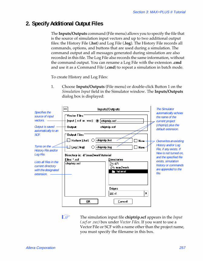
Section 3: MAX+PLUS II Tutorial
81_GSBOOK.fm5 Page 257 Tuesday, October 14, 1997 4:04 PM
2. Specify Additional Output Files
The Inputs/Outputs command (File menu) allows you to specify the file that is the source of simulation input vectors and up to two additional output files: the History File (.hst) and Log File (.log). The History File records all commands, options, and buttons that are used during a simulation. The command output and all messages generated during simulation are also recorded in this file. The Log File also records the same information, without the command output. You can rename a Log File with the extension .cmd and use it as a Command File (.cmd) to repeat a simulation in batch mode.
To create History and Log Files:
1. Choose Inputs/Outputs (File menu) or double-click Button 1 on the Simulation Input field in the Simulator window. The Inputs/Outputs dialog box is displayed:
1 The simulation input file chiptrip.scf appears in the Input (.scf or .vec) box under Vector Files. If you want to use a Vector File or SCF with a name other than the project name, you must specify the filename in this box.
Specifies the source of input vectors.
Output is saved automatically to an SCF.
Turns on the History File and/or Log File.
Lists all files in the current directory with the designated extension.
The Simulator automatically echoes the name of the current project (chiptrip) plus the default extension.
Overwrites an existing History and/or Log File, if any exists. If New is not turned on, and the specified file exists, simulation history or commands are appended to the file.
Altera Corporation 257

MAX+PLUS II Getting Started
81_GSBOOK.fm5 Page 258 Tuesday, October 14, 1997 4:04 PM
Simulation outputs are automatically saved to an SCF with the same filename as the input file.
2. Turn on the History (.hst) and Log (.log) options under Output Files. The filenames chiptrip.hst and chiptrip.log appear automatically in the History (.hst) and Log (.log) boxes.
3. Choose OK.
3. Turn On Setup & Hold Time Monitoring
You can monitor the project to determine whether setup and hold time violations occur during simulation.
To turn on setup and hold time monitoring:
v Turn on the Setup/Hold option in the Simulator window.
4. Run the Simulation
To simulate the project:
1. Choose the Start button.
The Simulator immediately begins to simulate the chiptrip project. As the Simulator processes the input vectors and simulates the project, the progress bar moves toward 100%, the Simulation Time field is dynamically updated, and the output logic levels are recorded in chiptrip.scf.
The Simulator runs in the background, freeing your computer for other work. However, this simulation is short and you will not have to wait long for it to finish. When you analyze a larger, more complex project, you can always start a simulation and then switch to another application to continue your work.
1 If you wish to view the simulation outputs as they are written to chiptrip.scf, you can open the file in the Waveform Editor. However, leaving an SCF window open during simulation can reduce the speed of your simulation.
258 Altera Corporation
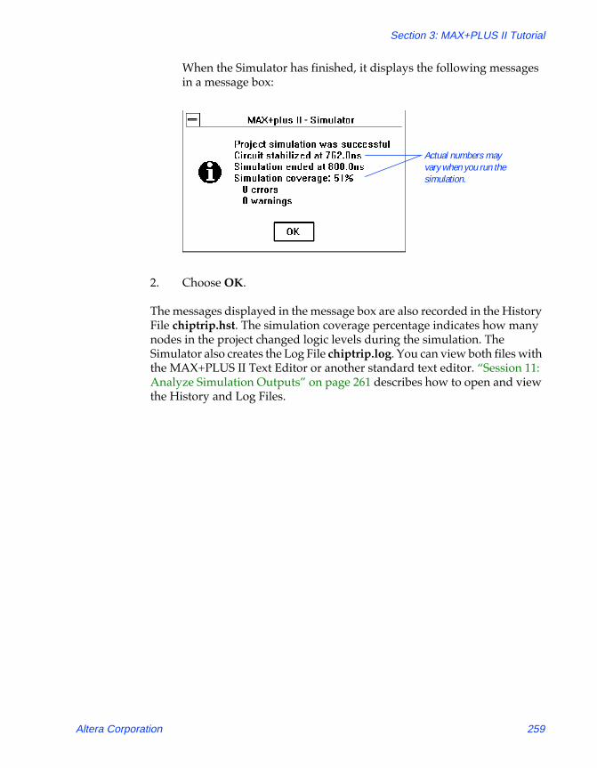
Section 3: MAX+PLUS II Tutorial
81_GSBOOK.fm5 Page 259 Tuesday, October 14, 1997 4:04 PM
When the Simulator has finished, it displays the following messages in a message box:
2. Choose OK.
The messages displayed in the message box are also recorded in the History File chiptrip.hst. The simulation coverage percentage indicates how many nodes in the project changed logic levels during the simulation. The Simulator also creates the Log File chiptrip.log. You can view both files with the MAX+PLUS II Text Editor or another standard text editor. ÒSession 11: Analyze Simulation OutputsÓ on page 261 describes how to open and view the History and Log Files.
Actual numbers may vary when you run the simulation.
Altera Corporation 259
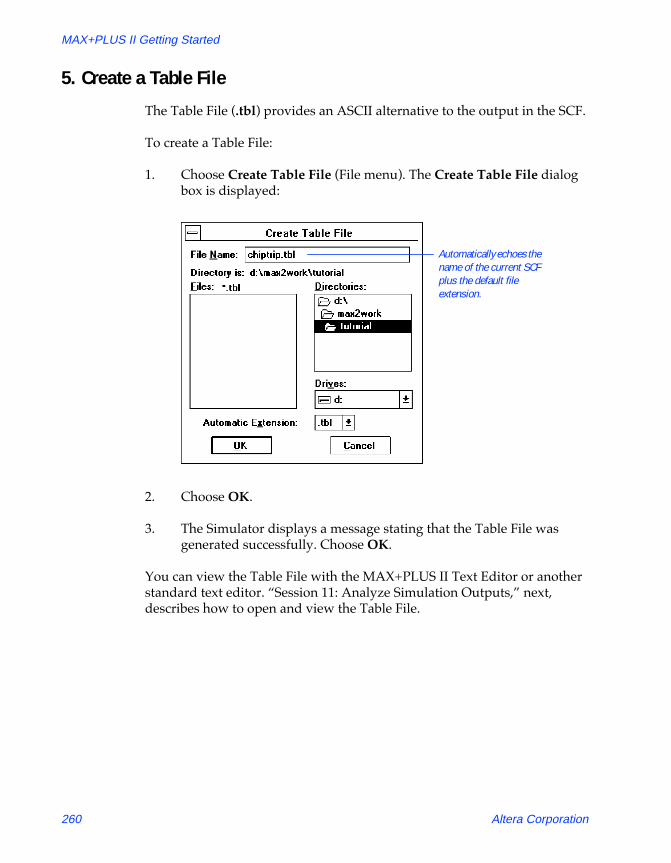
MAX+PLUS II Getting Started
81_GSBOOK.fm5 Page 260 Tuesday, October 14, 1997 4:04 PM
5. Create a Table File
The Table File (.tbl) provides an ASCII alternative to the output in the SCF.
To create a Table File:
1. Choose Create Table File (File menu). The Create Table File dialog box is displayed:
2. Choose OK.
3. The Simulator displays a message stating that the Table File was generated successfully. Choose OK.
You can view the Table File with the MAX+PLUS II Text Editor or another standard text editor. ÒSession 11: Analyze Simulation Outputs,Ó next, describes how to open and view the Table File.
Automatically echoes the name of the current SCF plus the default file extension.
260 Altera Corporation

Section 3: MAX+PLUS II Tutorial
81_GSBOOK.fm5 Page 261 Tuesday, October 14, 1997 4:04 PM
Session 11: Analyze Simulation Outputs
In this session, you will use the MAX+PLUS II Waveform Editor and Text Editor to view the results of simulation. This session includes the following steps:
1. View the Simulator Channel File.2. View the History, Log, and Table Files.3. Re-edit your SCF if necessary.4. Create, simulate, and analyze finish.scf.
1. View the Simulator Channel File
v Choose the Open SCF button in the Simulator window to open chiptrip.scf, the SCF for the current project.
1 If you did not close chiptrip.scf at the end of Session 9, you can also choose Waveform Editor (MAX+PLUS II menu) to bring the most recently active Waveform Editor window to the front.
Now that you have simulated the output node waveforms, their logic levels are defined. The following illustration shows the outputs MAX+PLUS II creates in chiptrip.scf after simulation. Try scrolling left and right, or use the Zoom In and Zoom Out commands (View menu) to examine the file.
Altera Corporation 261

MAX+PLUS II Getting Started
81_GSBOOK.fm5 Page 262 Tuesday, October 14, 1997 4:04 PM
Your directional input signals, dir1 and dir0, and the clock pulses create the outputs in auto_max:1|street_map waveform that represent your vehicleÕs progress along the zigzag route to Altera. The states on the street_map output change at each Clock cycle in the following pattern: yc, rpt, mpld, epld, gdf, cnf, epm, and altera. (Refer to the map in Figure 3-6 on page 245.) Because the accel acceleration input remains low throughout the SCF, the speed_ch:2|speed output reflects a legal state, and the ticket[3..0] group has a low (0) logic level, i.e., no speeding tickets.
To view the exact time at each logic level transition:
1. If necessary, press Button 1 on the Reference cursor handle and drag it to the beginning of the file.
2. Click Button 1 on the right Reference cursor movement button, as shown in the previous illustration, to move the Reference cursor to the first logic level transition in the file.
Low logic level on acceleration input is reflected in the “legal” state.
Movement buttons for Reference cursor
Reference cursor
The correct directional inputs result in successful traversal of zigzag route.
Low logic level on acceleration input results in no tickets.
262 Altera Corporation

Section 3: MAX+PLUS II Tutorial
81_GSBOOK.fm5 Page 263 Tuesday, October 14, 1997 4:04 PM
3. Continue clicking Button 1 on the right Reference cursor movement button to view subsequent logic level transitions.
The time at the Reference cursor location is displayed both at the top of the cursor and in the Reference field. Each transition shows the exact time and location of the signalÕs change in logic level or state.
2. View the History, Log & Table Files
You can view the History, Log, and Table Files for additional information about your simulation. Use the History File (.hst) to review the entire history of your simulation. The Log File (.log) is similar to the History File, but without the command outputs; it can be saved as a Command File (.cmd) and used to run batch-mode simulation. The Table File (.tbl) is a text file that contains the same information as the current SCF or Waveform Design File (.wdf). A Table File has the same format as a Vector File (.vec).
To view the History, Log, or Table File:
1. Choose Open (File menu).
2. Select Text Editor files and choose the .hst, .log, or .tbl extension in the drop-down list box.
3. Double-click Button 1 on the appropriate chiptrip file in the Files box.
MAX+PLUS II automatically opens the Text Editor window and displays the file you selected.
Altera Corporation 263

MAX+PLUS II Getting Started
81_GSBOOK.fm5 Page 264 Tuesday, October 14, 1997 4:04 PM
The following illustration shows the Table File chiptrip.tbl:
3. Re-Edit Your SCF if Necessary
You may need to edit your inputs and simulate your project repeatedly to obtain the desired simulation results. Even very experienced digital designers simulate their designs many times with multiple sets of inputs. MAX+PLUS II allows you to quickly complete many different simulation runs to verify the functionality of your logic circuit design. You should use the Simulator to exhaustively test your project before you program it into a device.
Simulation results are saved in Vector File format.
264 Altera Corporation

Section 3: MAX+PLUS II Tutorial
81_GSBOOK.fm5 Page 265 Tuesday, October 14, 1997 4:04 PM
4. Create, Simulate & Analyze finish.scf
To practice your new skills, return to ÒSession 9: Create a Simulator Channel FileÓ on page 245 and create another SCF called finish.scf. Your challenge will be to plot a path on the logic circuit map shown on page 245 that takes you from your company to Altera as quickly as possible with the fewest speeding tickets.
1 Because finish.scf contains the same nodes and groups as chiptrip.scf, you can use Save As (File menu) to save chiptrip.scf as finish.scf, and proceed to edit the input nodes. As a shortcut, you can also copy finish.scf from the \max2work\chiptrip subdirectory.
Once you successfully drive from your company to Altera by creating and simulating finish.scf, you might try one of the following challenges, or plot your own itinerary:
■ Travel from your company to Altera as quickly as possible, passing through all intersections, with as few tickets as possible.
■ Travel from your company to Altera as quickly as possible, regardless of tickets.
Altera Corporation 265

MAX+PLUS II Getting Started
81_GSBOOK.fm5 Page 266 Tuesday, October 14, 1997 4:04 PM
Session 12: Analyze Timing
In this session, you will use the Timing Analyzer to analyze the performance of the chiptrip project. The Timing Analyzer offers three analysis modes:
You will use the timing Simulator Netlist File (.snf) generated in ÒSession 6: Compile the ProjectÓ on page 216 to analyze the propagation delays in the chiptrip project. This session includes the following steps:
1. Open the Timing Analyzer window.2. Run the Timing Analyzer.3. List a propagation delay message.4. Locate the delay path in the Floorplan Editor.5. Locate the delay path in the projectÕs design files.6. Run a timing analysis in another mode.
Analysis Mode: Description:
Delay Matrix Analyzes the propagation delay paths between multiple source and destination nodes.
Registered Performance Analyzes registered logic for a performance-limiting delay, minimum Clock period, and maximum circuit frequency.
Setup/Hold Matrix Calculates the minimum setup and hold time requirements from input pins to signal inputs of flipflops, latches, and asynchronous RAM.
266 Altera Corporation

Section 3: MAX+PLUS II Tutorial
81_GSBOOK.fm5 Page 267 Tuesday, October 14, 1997 4:04 PM
1. Open the Timing Analyzer Window
To open the Timing Analyzer window:
1. Choose Timing Analyzer (MAX+PLUS II menu).
2. If necessary, click Button 1 on the Maximize button in the title bar to maximize the window.
3. If the Delay Matrix is not already displayed, choose Delay Matrix (Analysis menu).
The Timing Analyzer automatically loads the timing SNF for the chiptrip project.
See the following illustration:
The current project is loaded automatically.
When default timing tagging is used, source and destination nodes are not shown until the Timing Analyzer has been run.
Altera Corporation 267
MAX+PLUS II Getting Started
81_GSBOOK.fm5 Page 268 Tuesday, October 14, 1997 4:04 PM
The Timing Analyzer automatically ÒtagsÓ all input pins as timing sources and all output pins as timing destinations for Delay Matrix analysis. The names of nodes with this Òdefault timing analysis taggingÓ are not visible until after the analysis is run. Each of the three analysis modes has its own display and appropriate default timing analysis tagging for nodes.
You can tag specific nodes for analysis in the Timing Analyzer; in the Floorplan Editor; or in the original project design files in the Graphic, Text, and Waveform Editors. The Timing Analysis Source and Timing Analysis Destination commands are provided in all of these MAX+PLUS II applications.
f Choose the context-sensitive help button h and click Button 1 anywhere within the matrix to go to ÒDelay Matrix DisplayÓ in MAX+PLUS II Help.
2. Run the Timing Analyzer
To run a timing analysis:
1. Turn on the Cut Off I/O Pin Feedback command (Options menu). When this command is turned on, the Timing Analyzer uses bidirectional I/O pins only as source and destination nodes; feedback from within the device is excluded.
2. Turn off the Cut Off Clear & Preset Paths command (Options menu). When this command is turned off, the Timing Analyzer calculates paths that travel through the Clear and Preset inputs to D flipflops. If a design does not use Clear or Preset signals, or if you do not wish to display paths that travel through Clear and Preset inputs to D flipflops, you can turn this command on.
3. Choose Start. The Timing Analyzer immediately begins to analyze the chiptrip project and calculate the minimum and maximum propagation delays between each pair of nodes that are connected in the project. The progress bar moves toward 100%.
1 You can also run a timing analysis by choosing Analyze Timing (Utilities menu) in the Graphic, Text, Waveform, or Floorplan Editor.
268 Altera Corporation
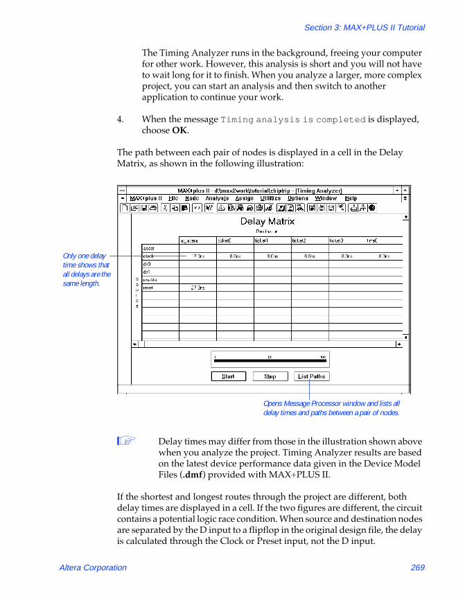
Section 3: MAX+PLUS II Tutorial
81_GSBOOK.fm5 Page 269 Tuesday, October 14, 1997 4:04 PM
The Timing Analyzer runs in the background, freeing your computer for other work. However, this analysis is short and you will not have to wait long for it to finish. When you analyze a larger, more complex project, you can start an analysis and then switch to another application to continue your work.
4. When the message Timing analysis is completed is displayed, choose OK.
The path between each pair of nodes is displayed in a cell in the Delay Matrix, as shown in the following illustration:
1 Delay times may differ from those in the illustration shown above when you analyze the project. Timing Analyzer results are based on the latest device performance data given in the Device Model Files (.dmf) provided with MAX+PLUS II.
If the shortest and longest routes through the project are different, both delay times are displayed in a cell. If the two figures are different, the circuit contains a potential logic race condition. When source and destination nodes are separated by the D input to a flipflop in the original design file, the delay is calculated through the Clock or Preset input, not the D input.
Only one delay time shows that all delays are the same length.
Opens Message Processor window and lists all delay times and paths between a pair of nodes.
Altera Corporation 269

MAX+PLUS II Getting Started
81_GSBOOK.fm5 Page 270 Tuesday, October 14, 1997 4:04 PM
3. List a Propagation Delay Message
To list the delays for the signal paths represented by a cell:
1. Select the cell for clock and at_altera.
2. Turn on the List Only Longest Path command (Options menu). When this command is turned on before you choose the List Paths button, the Timing Analyzer displays only the longest delay path in the Message Processor window.
3. Choose the List Paths button. The Message Processor window opens and lists the longest delay path between the clock and at_altera nodes.
4. The message Finished listing longest delay path(s) is displayed. Choose OK.
5. If necessary, choose Message Processor (MAX+PLUS II menu) to bring the Message Processor window to the front.
See the following illustration:
The delay path from clock to at_altera is 17.0ns.
270 Altera Corporation

Section 3: MAX+PLUS II Tutorial
81_GSBOOK.fm5 Page 271 Tuesday, October 14, 1997 4:04 PM
4. Locate the Delay Path in the Floorplan Editor
You can direct the Message Processor to locate the path represented by a message in the Floorplan Editor. You can either locate each source of a message in succession, or locate all sources simultaneously.
To locate all sources of a message simultaneously in the Floorplan Editor:
1. In the Message Processor window, click Button 1 on the message or on the right side of the Message button to select the message Info: Delay path from 'clock' to 'at_altera': 17.0ns.
2. Turn on the Locate in Floorplan Editor option. The Locate All button becomes active (i.e., undimmed).
3. Choose the Locate All button. MAX+PLUS II automatically opens the Floorplan Editor window and highlights all sources of the message simultaneously.
4. If necessary, turn on the LAB View and Last Compilation Floorplan commands (Layout menu) and the Show Path command (Options menu); and turn off the Report File Equation Viewer command (Layout menu). The full path from the clock source node to the at_altera destination node is displayed, as shown in the following illustration:
Show Path button
Altera Corporation 271

MAX+PLUS II Getting Started
81_GSBOOK.fm5 Page 272 Tuesday, October 14, 1997 4:04 PM
5. Once you finish viewing the Floorplan Editor, close the Floorplan Editor window and return to the Timing Analyzer.
5. Locate the Delay Path in the Project’s Design Files
You can direct the Message Processor to locate the path represented by a message in the original design file(s) for a project.
To locate the sources of a the message in the chiptrip projectÕs design files:
1. In the Message Processor window, click Button 1 on the message or on the right side of the Message button to select the message Info: Delay path from 'clock' to 'at_altera': 17.0ns.
2. Turn off the Locate in Floorplan Editor option.
3. Click Button 1 on the right side of the Locate button to locate the first of four sources for the message. MAX+PLUS II automatically opens the file chiptrip.gdf in a Graphic Editor window and highlights the clock input pin.
4. Locate each of the other three sources by clicking Button 1 on the right side of the Locate button. MAX+PLUS II automatically opens the appropriate design editor for each successive message source.
You can close any open editor window(s) and the Message Processor and return to the Timing Analyzer to select other cells, list delay path messages, and locate the paths in either the Floorplan Editor or the source design files for the project.
6. Run a Timing Analysis in Another Mode
v Return to the Timing Analyzer window, choose Registered Performance or Setup/Hold Matrix (Analysis menu), and choose Start to run the Timing Analyzer again.
272 Altera Corporation
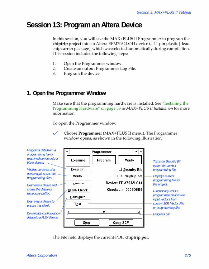
Section 3: MAX+PLUS II Tutorial
81_GSBOOK.fm5 Page 273 Tuesday, October 14, 1997 4:04 PM
Session 13: Program an Altera Device
In this session, you will use the MAX+PLUS II Programmer to program the chiptrip project into an Altera EPM7032LC44 device (a 44-pin plastic J-lead chip carrier package), which was selected automatically during compilation. This session includes the following steps:
1. Open the Programmer window.2. Create an output Programmer Log File.3. Program the device.
1. Open the Programmer Window
Make sure that the programming hardware is installed. See ÒInstalling the Programming HardwareÓ on page 53 in MAX+PLUS II Installation for more information.
To open the Programmer window:
v Choose Programmer (MAX+PLUS II menu). The Programmer window opens, as shown in the following illustration:
The File field displays the current POF, chiptrip.pof.
Programs data from a programming file or examined device onto a blank device.
Verifies contents of a device against current programming data.
Examines a device to ensure it is blank.
Functionally tests a programmed device with input vectors from current SCF, Vector File, or programming file.
Turns on Security Bit option for current programming file.
Displays current programming file for the project.
Progress bar
Examines a device and stores the data in a temporary buffer.
Downloads configuration data into a FLEX device.
Altera Corporation 273

MAX+PLUS II Getting Started
81_GSBOOK.fm5 Page 274 Tuesday, October 14, 1997 4:04 PM
1 If chiptrip.pof is not shown, use the Select Programming File command (File menu) to select chiptrip.pof as your programming file. You will be asked whether you wish to change the current project to chiptrip. Choose OK.
2. Create an Output Programmer Log File
MAX+PLUS II optionally records all Programmer actions and messages in a Programmer Log File (.plf).
To create an output PLF:
1. Choose Inputs/Outputs (File menu). The Inputs/Outputs dialog box is displayed:
2. If necessary, turn on the Log (.plf) option under Output File. The filename chiptrip.plf appears automatically in the Log (.plf) box.
Overwrites the current PLF, if one exists. If New is not turned on, and the specified file exists, programming commands and messages are appended to the file.
The Programmer automatically echoes the current project name plus the default file extension.
Specifies the source of input vectors for functional testing.
Turns on the Programmer Log File.
274 Altera Corporation

Section 3: MAX+PLUS II Tutorial
81_GSBOOK.fm5 Page 275 Tuesday, October 14, 1997 4:04 PM
3. Choose OK.
f Press F1 when the Inputs/Outputs dialog box is displayed to go toÒInputs/Outputs CommandÓ in MAX+PLUS II Help.
3. Program the Device
To program the device:
1. Insert an EPM7032LC44-6 device into the programming socket.
2. Choose the Program button.
The Programmer examines the device, programs the chiptrip project into the device, and checks that the contents of the device match those of the chiptrip.pof file. Once programming is complete, you can view the PLF if you wish. For more information on how to open and view text files, see Ò2. View the History, Log & Table FilesÓ on page 263.
3. Double-click Button 1 on the document icon (or box) to close the Programmer window.
f Go to ÒInserting a Device into the SocketÓ and ÒProgramming a Single Device with the Master Programming UnitÓ using Search for Help on (Help menu).
Altera Corporation 275

MAX+PLUS II Getting Started
81_GSBOOK.fm5 Page 276 Tuesday, October 14, 1997 4:04 PM
Are We There Yet?
Congratulations on finishing the tutorial! If you would like to further practice what you have learned, you can return to selected sessions and try the following:
■ Try creating the subdesigns with different design entry methods, e.g., create the speed_ch subdesign as a Text Design File (.tdf).
■ Compile the chiptrip project for different devices. For example, try the EPM9320 device and run a new timing analysis.
■ Compile and simulate the project for different speed grades of the same device.
■ Run timing analyses for the new devices.
■ If you recompile the project for a different device, try programming the actual device.
276 Altera Corporation