section 3 - dickman supply, inc.downloads.dickmansupply.com/pdf/acme/pdpd01.pdf · section1...
TRANSCRIPT

Transformer Questions & Answers . . . . . . . . . . . . . . . . . . . . . . . . . . . . . . . . . . . . . . . . . . . . . . . .6--10Selection Steps . . . . . . . . . . . . . . . . . . . . . . . . . . . . . . . . . . . . . . . . . . . . . . . . . . . . . . . . . . . . . . .11-12Construction Features . . . . . . . . . . . . . . . . . . . . . . . . . . . . . . . . . . . . . . . . . . . . . . . . . . . . . . . . . .13-16316 Stainless Steel Transformers . . . . . . . . . . . . . . . . . . . . . . . . . . . . . . . . . . . . . . . . . . . . . . .17 & 24LN Series –Low Noise Transformers . . . . . . . . . . . . . . . . . . . . . . . . . . . . . . . . . . . . . . . . . . .24, & 25Selection Charts, 1Ø and 3Ø . . . . . . . . . . . . . . . . . . . . . . . . . . . . . . . . . . . . . . . . . . . . . . . . . . . .17-29Auto-Transformers . . . . . . . . . . . . . . . . . . . . . . . . . . . . . . . . . . . . . . . . . . . . . . . . . . . . . . . . . . . . . . .29Auto Arrangements (Using 2 Single Phase) . . . . . . . . . . . . . . . . . . . . . . . . . . . . . . . . . . . . . . . . . . .30Auto Zig-Zag Transformers . . . . . . . . . . . . . . . . . . . . . . . . . . . . . . . . . . . . . . . . . . . . . . . . . . . . . . . . .31Non-Standard 3Ø Applications . . . . . . . . . . . . . . . . . . . . . . . . . . . . . . . . . . . . . . . . . . . . . . . . . . . . . .32Design Figures, Wiring Diagrams & Accessories . . . . . . . . . . . . . . . . . . . . . . . . . . . . . . . . . .146-158
© 2005 Acme Electric CorporationInformation contained in this catalog is subject to change without notice and therefore cannot be guaranteed by Acme.
Introduction . . . . . . . . . . . . . . . . . . . . . . . . . . . . . . . . . . . . . . . . . . . . . . . . . . . . . . . . . . . . . . . . . . . . . .4
General Description . . . . . . . . . . . . . . . . . . . . . . . . . . . . . . . . . . . . . . . . . . . . . . . . . . . . . . . . . . . .34-36Cost Efficiencies & Examples . . . . . . . . . . . . . . . . . . . . . . . . . . . . . . . . . . . . . . . . . . . . . . . . . . . . . .36Selection Charts . . . . . . . . . . . . . . . . . . . . . . . . . . . . . . . . . . . . . . . . . . . . . . . . . . . . . . . . . . . . . .37-40Design Figures, Wiring Diagrams & Accessories . . . . . . . . . . . . . . . . . . . . . . . . . . . . . . . . . .146-158
Harmonic Mitigating Transformers . . . . . . . . . . . . . . . . . . . . . . . . . . . . . . . . . . . . . . . . . . . . . . . .42-43Non-Linear Description & Features . . . . . . . . . . . . . . . . . . . . . . . . . . . . . . . . . . . . . . . . . . . . . . .44-45Non-Linear Selection Charts . . . . . . . . . . . . . . . . . . . . . . . . . . . . . . . . . . . . . . . . . . . . . . . . . . . . .46-51Non-Linear Definition of Terms . . . . . . . . . . . . . . . . . . . . . . . . . . . . . . . . . . . . . . . . . . . . . . . . . . . . .52Design Figures, Wiring Diagrams & Accessories . . . . . . . . . . . . . . . . . . . . . . . . . . . . . . . . . .146-158
General Description & Features . . . . . . . . . . . . . . . . . . . . . . . . . . . . . . . . . . . . . . . . . . . . . . . . . .54-55Selection Charts . . . . . . . . . . . . . . . . . . . . . . . . . . . . . . . . . . . . . . . . . . . . . . . . . . . . . . . . . . . . . .56-57Windings, Terminations & Construction . . . . . . . . . . . . . . . . . . . . . . . . . . . . . . . . . . . . . . . . . . . . . .57Thermal Switches . . . . . . . . . . . . . . . . . . . . . . . . . . . . . . . . . . . . . . . . . . . . . . . . . . . . . . . . . . . . . . . .57AC Line Reactors & Encapsulated AC Line Reactors General Descriptions . . . . . . . . . . . . . . .58-59AC Line Reactors Selection Charts . . . . . . . . . . . . . . . . . . . . . . . . . . . . . . . . . . . . . . . . . . . . . . . . . .60AC Line Reactors Dimensional Drawings . . . . . . . . . . . . . . . . . . . . . . . . . . . . . . . . . . . . . . . . . . . . .58Encapsulated AC Line Reactors Genral Description . . . . . . . . . . . . . . . . . . . . . . . . . . . . . . . . . . . . .61Encapsulated AC Line Reactors Selection Charts . . . . . . . . . . . . . . . . . . . . . . . . . . . . . . . . . . . . . . .62Encapsulated AC Line Reactors Wiring Diagrams . . . . . . . . . . . . . . . . . . . . . . . . . . . . . . . . . . . . . .61
Selection Steps . . . . . . . . . . . . . . . . . . . . . . . . . . . . . . . . . . . . . . . . . . . . . . . . . . . . . . . . . . . . . . . . . .64TA Series Open Core & Coil Construction Features . . . . . . . . . . . . . . . . . . . . . . . . . . . . . . . . . . . . .65TA Series Open Core & Coil Primary & Secondary Fuse Sizing Info . . . . . . . . . . . . . . . . . . . . .66-67TA Series Open Core & Coil Jumper Link Connections . . . . . . . . . . . . . . . . . . . . . . . . . . . . . . . . . .67TA Series Open Core & Coil Primary & Secondary Fuse Sizing Info Fuse Kits . . . . . . . . . . . . .66-67TA Series Open Core & Coil Wiring Diagrams & Dimensional Drawings . . . . . . . . . . . . . . . . . . . .77TB Series Open Core & Coil General Description & Features . . . . . . . . . . . . . . . . . . . . . . . . . . . .68TB Series Open Core & Coil Primary & Secondary Fuse Sizing Info . . . . . . . . . . . . . . . . . . . . .69-70TB Series Open Core & Coil Wiring Diagrams & Dimensional Drawings . . . . . . . . . . . . . . . . . . . .78TA & TB Series Open Core & Coil Transformers Selection Charts . . . . . . . . . . . . . . . . . . . . . . .71-76Harsh Environment Control Transformers . . . . . . . . . . . . . . . . . . . . . . . . . . . . . . . . . . . . . . . . . . . . .79AE/CE Series Encapsulated Transformers . . . . . . . . . . . . . . . . . . . . . . . . . . . . . . . . . . . . . . . . . .80-87Finger/Guard® Industrial Control Transformers. . . . . . . . . . . . . . . . . . . . . . . . . . . . . . . . . . . . . .88-92
SECTION 1
SECTION 2
SECTION 3
SECTION 4
SECTION 5
TABLE OF CONTENTS
Dry-Type Distribution Transformers
Opti-Miser® Distribution Transformers
Non-LinearLoad® Transformers & Harmonic Mitigating Transformers
Drive Isolation Transformers & AC Line Reactors
Industrial Control Transformers
NEW
NEW
NEW
NEW
NEW
Description & Applications . . . . . . . . . . . . . . . . . . . . . . . . . . . . . . . . . . . . . . . . . . . . . . . . . . . . . . . .104Questions & Answers . . . . . . . . . . . . . . . . . . . . . . . . . . . . . . . . . . . . . . . . . . . . . . . . . . . . . . .105-109Selection Charts, Single Phase . . . . . . . . . . . . . . . . . . . . . . . . . . . . . . . . . . . . . . . . . . . . . . . .110-112Selection Charts, Three Phase . . . . . . . . . . . . . . . . . . . . . . . . . . . . . . . . . . . . . . . . . . . . . . . . .113-115Specifications & Dimensions . . . . . . . . . . . . . . . . . . . . . . . . . . . . . . . . . . . . . . . . . . . . . . . . . . . . . .116Wiring Diagrams . . . . . . . . . . . . . . . . . . . . . . . . . . . . . . . . . . . . . . . . . . . . . . . . . . . . . . . . . . . .117-118
304 Stainless Steel Panel-Tran® . . . . . . . . . . . . . . . . . . . . . . . . . . . . . . . . . . . . . . . . . . . . . . . . . . . .120General Description & Construction . . . . . . . . . . . . . . . . . . . . . . . . . . . . . . . . . . . . . . . . . . . . . . . .121Features . . . . . . . . . . . . . . . . . . . . . . . . . . . . . . . . . . . . . . . . . . . . . . . . . . . . . . . . . . . . . . . . . . . . . .121Selection Charts . . . . . . . . . . . . . . . . . . . . . . . . . . . . . . . . . . . . . . . . . . . . . . . . . . . . . . . . . . . .122-123Circuit Breaker Data . . . . . . . . . . . . . . . . . . . . . . . . . . . . . . . . . . . . . . . . . . . . . . . . . . . . . . . . .122-123Wiring Diagrams . . . . . . . . . . . . . . . . . . . . . . . . . . . . . . . . . . . . . . . . . . . . . . . . . . . . . . . . . . . . . . .124
Construction Features . . . . . . . . . . . . . . . . . . . . . . . . . . . . . . . . . . . . . . . . . . . . . . . . . . . . . . . . . . .126Selection Steps . . . . . . . . . . . . . . . . . . . . . . . . . . . . . . . . . . . . . . . . . . . . . . . . . . . . . . . . . . . . . . . .127Selection Charts . . . . . . . . . . . . . . . . . . . . . . . . . . . . . . . . . . . . . . . . . . . . . . . . . . . . . . . . . . . . . . . .128
True-Power® Constant Voltage Regulators &Power Line Conditioners
Introduction & Features . . . . . . . . . . . . . . . . . . . . . . . . . . . . . . . . . . . . . . . . . . . . . . . . . . . .130Specifications . . . . . . . . . . . . . . . . . . . . . . . . . . . . . . . . . . . . . . . . . . . . . . . . . . . . . . . . . . . .131Selection Charts, Portable & Hardwired . . . . . . . . . . . . . . . . . . . . . . . . . . . . . . . . . . . . . . .131Dimensional Drawings . . . . . . . . . . . . . . . . . . . . . . . . . . . . . . . . . . . . . . . . . . . . . . . . . . . . .132
DC Power SuppliesDIN-Rail Mounted Power Supplies . . . . . . . . . . . . . . . . . . . . . . . . . . . . . . . . . . . . . . . .134-136DR Series Accessories . . . . . . . . . . . . . . . . . . . . . . . . . . . . . . . . . . . . . . . . . . . . . . . . . . . . .137Unregulated Power Supplies
Blackline Series . . . . . . . . . . . . . . . . . . . . . . . . . . . . . . . . . . . . . . . . . . . . . . . . . . . . .138-139Regulated Power Supplies
SPS Blueline Series . . . . . . . . . . . . . . . . . . . . . . . . . . . . . . . . . . . . . . . . . . . . . . . . .140-141SPW Series . . . . . . . . . . . . . . . . . . . . . . . . . . . . . . . . . . . . . . . . . . . . . . . . . . . . . . . .142-143
Frequently Asked Questions . . . . . . . . . . . . . . . . . . . . . . . . . . . . . . . . . . . . . . . . . . . . . . . . . . . . . .144
Design Figures . . . . . . . . . . . . . . . . . . . . . . . . . . . . . . . . . . . . . . . . . . . . . . . . . . . . . . . . . . . . . . . . .146Wiring Diagrams . . . . . . . . . . . . . . . . . . . . . . . . . . . . . . . . . . . . . . . . . . . . . . . . . . . . . . . . . . . .147-156Transformer Accessories . . . . . . . . . . . . . . . . . . . . . . . . . . . . . . . . . . . . . . . . . . . . . . . . . . . . .157-158Acme Specifications Guide . . . . . . . . . . . . . . . . . . . . . . . . . . . . . . . . . . . . . . . . . . . . . . . . . . .159-162Industry Standards Data . . . . . . . . . . . . . . . . . . . . . . . . . . . . . . . . . . . . . . . . . . . . . . . . . . . . . . . . .163Alphanumerical Catalog Number Listing . . . . . . . . . . . . . . . . . . . . . . . . . . . . . . . . . . . . . . . . .164-168Product Warranty & Shielding Information . . . . . . . . . . . . . . . . . . . . . . . . . . . . . . .Inside Back Cover
SECTION 7
SECTION 8
SECTION 9
SECTION 10
GENERAL
Power Supply Features . . . . . . . . . . . . . . . . . . . . . . . . . . . . . . . . . . . . . . . . . . . . . . . . . . . . . . . . . . .94Selection Guide . . . . . . . . . . . . . . . . . . . . . . . . . . . . . . . . . . . . . . . . . . . . . . . . . . . . . . . . . . . . . . . . .95Power Supply Sizing Data . . . . . . . . . . . . . . . . . . . . . . . . . . . . . . . . . . . . . . . . . . . . . . . . . . . . . . . . .96Power Supplies With Timer & Photocell . . . . . . . . . . . . . . . . . . . . . . . . . . . . . . . . . . . . . . . . . . . . .97Power Supplies . . . . . . . . . . . . . . . . . . . . . . . . . . . . . . . . . . . . . . . . . . . . . . . . . . . . . . . . . . . . . . . . .98Pool & Spa Transformers . . . . . . . . . . . . . . . . . . . . . . . . . . . . . . . . . . . . . . . . . . . . . . . . . . . . . . . . . .99General Purpose Low Voltage Transformers . . . . . . . . . . . . . . . . . . . . . . . . . . . . . . . . . . . . . . . . .100Buck-Boost Lighting Transformers . . . . . . . . . . . . . . . . . . . . . . . . . . . . . . . . . . . . . . . . . . . . . . . . .101Wiring Diagrams . . . . . . . . . . . . . . . . . . . . . . . . . . . . . . . . . . . . . . . . . . . . . . . . . . . . . . . . . . . . . . .102
Low Voltage Lighting Transformers & Power SuppliesSECTION 6
TABLE OF CONTENTS
Buck-Boost Transformers
Panel-Tran® Zone Power Centers
Air Conditioning, Refrigeration & Appliance Transformers
Power Conditioning Products
General Information
NEW
For over eighty-eight years, Acme Electric has beenmanufacturing Power Conditioning Equipment for use in industrial, commercial and OEM applications. Built on a reputation for superior service, quality and technicalexpertise in the transformer market, Acmeis regarded as a true industry leader.
Acme Electric is a full line manufacturerof low voltage (600V and below) dry typedistribution transformers using both copperand aluminum conductor, offering an arrayof products between 0.05 -1000 KVA.
Headquartered in Lumberton, NorthCarolina, Acme Electric has over 170,000 square ft. ofmanufacturing in two plants; a 130,000 square ft. facilityin Lumberton and a 45,000 square ft. facility in Mexico.
Acme s product offering covers the full spectrum ofapplications, from commercial general power distributionand high harmonic conditions to specific industrial motordrive/factory automation systems, to low voltage landscapelighting applications.
As an active member of the Rockwell AutomationEncompass Program, National Electrical ManufacturersAssociation (NEMA) and IEEE, Acme Electric markets itsapproximately 1,500 products through a selective networkof full line independent, regional, national and internationalelectrical distributors that are recognized in the industry asbeing best in class.
Manufacturing CapabilitiesTo meet the demands of the customer base, while maintaining a competitiveedge, strategically, Acme has focused onbeing a high quality, responsive, low costmanufacturer. All Acme products aredesigned, constructed and rated to meet or exceed the standards established by UL,CSA, CE, NEMA, ANSI and IEEE.
In 1997, Acme became certified in theDemand Flow Technology (DFT), in doingso, the cycle time for manufacturing atransformer has been reduced to 8-10 days. This flexibleprocess allows Acme the ability to provide standard andcustom product, with the responsiveness required froma manufacturer in today s just in time environment.
The Lumberton, North Carolina facility serves as Acme sheadquarters and primary manufacturing location. TheLumberton plant manufactures both air-cooled andencapsulated transformers covering the full range ofAcme s offering in standard and custom designs. Thisfacility also has 30,000 sq. ft of warehouse area thatserves as the company s central distribution center.
In 1999, Acme began its manufacturing expansion withthe opening of a facility in Monterrey, Mexico. This plantfocuses on many of the smaller KVA and industrial controltransformers that are sold throughout the entire AcmeElectric customer base. In 2003, Acme further expandedits manufacturing resources with a strategic partnershipin China.
In August 2004, we acquired Amveco Magnetics,Inc., Houston, TX. Amveco is a world leader intoroidal power transformers. Amveco designsand manufacturers toroidal power transformers,standard and custom inductors, current
transformers and auto-transformers. Most of the productsmanufactured by Amveco are custom designed, withthe use of proprietary CAD program and an experiencedEngineering Department. Amveco's knowledgable
customer service representatives providepromt, reliable and quality customerservice to all customers. Amveco is anISO-9001 registered company and thetransformers use only flame-retardantmaterial (UL 94V2). These transformerscarry a lifetime warranty and are recognized to several UL standardCSA certified, and TUV for medical
applications. Amveco expanded our global presence byincluding a joint venture in India.
Custom/OEM Product CapabilitiesIn addition to the full line of standard product offerings,Acme is positioned to supply special products to meetspecific customer requirements. With an OEM orientedend user customer base, an experienced Design Engineer-ing Department utilizes software dedicated to core andcoil electrical design, combined with new state of theart parametric technology mechanical design software.
With these design tools, Acme provides customers withrapid turnaround of designs and prototypes of customproducts. These custom designs range from special KVA,voltage combinations and performance characteristics tospecial mounting configurations/ footprints, enclosuresand terminations.
Commitment to QualityAcme Electric has earned the reputation forthe manufacture of high quality productsbacked by superior customer service. Todemonstrate this commitment to qualityAcme Electric is an ISO 9000 certifiedmanufacturer and has recently adopted a company wide Six Sigma philosophy ofcontinuous improvement.
As an ISO 9000 Certified Manufacturer,Acme Electric has adopted a specific,
proven quality management system. The Lumberton,NC facility has been ISO Certified since 1995 and in Mayof 2003 upgraded to the new ISO 9001- 2000 Standard.This certification expands beyond manufacturing to alsoinclude customer service. The Mexico and China facilitiesoperate under the same practices of ISO 9001-2000.
In 2002, Acme Electric made a commitment to the SixSigma philosophy. The result is a core team of certifiedblack belt and green belt project champions, who work inconjunction with the Acme Management Team andQuality Council to be the driving force behind Acme sdoctrine and goal of continuous improvement.
This philosophy involves all aspects of Acme s business(both manufacturing and in the office) and is having adirect impact on Acme s pledge to meet and exceed theexpectations of our customers.
With this commitment to quality, Acme haspositioned itself to be the premiere supplierof quality products and service to meet thedemanding needs of today s marketplace,while adapting to the dynamic changes oftomorrow.
Leadership in Quality Designed ProductsAndQualityCustomer Satisfaction
ACME ELECTRIC CORPORATION
Acme Electric, Power Distribution Products Catalogcontains many new productsfor your power distribution andcontrol applications. To receiveindividual catalogs on severalof our product lines, [email protected].
To make your selection processeasier, this catalog is dividedinto ten product sections.Selection charts in each sectionare also color coded:
Section color + white bars = 1Ø transformers
Section color + gray bar = 3Ø transformers
To find a product in the catalogwhen only the catalog numberis known, a complete alpha-numerical catalog number indexwith page number listing isprovided, beginning on page 164.
Wiring diagrams, design figuresand accessories for standard distribution transformers (Sections I - IV) begin onpage 146.
Some of the most frequentlyasked questions about trans-formers and their answers canbe found in Section I beginingon page 6. If you have additionalquestions before or after purchase of any products supplied by Power DistributionProducts, feel free to contact ourTechnical Services Department at 1-800-334-5214.
Thank you for selecting AcmePower Distribution Products.
Dimensions in the tablesare approximated and subject to change. Certifieddrawings for constructionpurposes will be providedupon request.

SECTION
600 Volt Class and BelowSingle and Three Phase
Transformer Questions & Answers . . . . .6-10
Enclosure Definitions . . . . . . . . . . . . . . . . . .10
Steps in Transformer Selection . . . . . . . .11-12
Construction Features . . . . . . . . . . . . . . .13-16
316 Stainless Steel Transformers . . . .17 & 24
Low Noise Series . . . . . . . . . . . . . . . . .24 - 25
Selection Charts 1Ø & 3Ø . . . . . . . . . . . .17-29
600 V Primary Units, 3Ø . . . . . . . . . . . . .26-27
Economical Auto Arrangements . . . . . . . . .30
Auto Zig-Zag Transformers . . . . . . . . . . . . . .31
Non-Standard Three Phase Applications . . .32
DR -T PEDISTRIB TION
TRANSFORMERS
NOTE: Design figures, wiring diagrams and accessories begin on page 146.
1
NEW
NEW

SECTION DRY-TYPE DISTRIBUTION TRANSFORMERS1
ACME ELECTRIC, POWER DISTRIBUTION PRODUCTS DIVISION • LUMBERTON, NC • 800-334-5214 • www.acmepowerdist.com6
1. What is a transformer and how does it work?A transformer is an electrical apparatus designed to convertalternating current from one voltage to another. It can bedesigned to step up or step down voltages and workson the magnetic induction principle. A transformer has nomoving parts and is a completely static solid state device,which insures, under normal operating conditions, a long andtrouble-free life. It consists, in its simplest form, of two ormore coils of insulated wire wound on a laminated steel core.When voltage is introduced to one coil, called the primary, it magnetizes the iron core. A voltage is then induced in theother coil, called the secondary or output coil. The change ofvoltage (or voltage ratio) between the primary and secondarydepends on the turns ratio of the two coils.2. What are taps and when are they used? Tapsare provided on some transformers on the high voltagewinding to correct for high or low voltage conditions, and stilldeliver full rated output voltages at the secondary terminals.Standard tap arrangements are at two-and-one-half and fivepercent of the rated primary voltage for both high and lowvoltage conditions. For example, if the transformer has a 480volt primary and the available line voltage is running at 504volts, the primary should be connected to the 5% tap abovenormal in order that the secondary voltage be maintained atthe proper rating. The standard ASA and NEMA designationfor taps are ANFC (above normal full capacity) and BNFC(below normal full capacity).3. What is the difference between Insulating,Isolating, and Shielded Winding transformers?
Insulating and isolating transformers are identical. These termsare used to describe the isolation of the primary and secondarywindings, or insulation between the two. A shielded transformeris designed with a metallic shield between the primary andsecondary windings to attenuate transient noise. This isespecially important in critical applications such as computers,process controllers and many other microprocessor controlleddevices. All two, three and four winding transformers are ofthe insulating or isolating types. Only autotransformers, whoseprimary and secondary are connected to each other electrically,are not of the insulating or isolating variety.4. Can transformers be operated at voltagesother than nameplate voltages? In some cases,transformers can be operated at voltages below the nameplaterated voltage. In NO case should a transformer be operated ata voltage in excess of its nameplate rating, unless taps areprovided for this purpose. When operating below the ratedvoltage, the KVA capacity is reduced correspondingly. Forexample, if a 480 volt primary transformer with a 240 voltsecondary is operated at 240 volts, the secondary voltage isreduced to 120 volts. If the transformer was originally rated 10KVA, the reduced rating would be 5 KVA, or in direct proportionto the applied voltage.5. Can 60 H transformers be operated at 50 H ?ACME transformers rated below 1 KVA can be used on 50 Hzservice. Transformers 1 KVA and larger, rated at 60 Hz, shouldnot be used on 50 Hz service, due to the higher losses andresultant heat rise. Special designs are required for this service.However, any 50 Hz transformer will operate on a 60 Hz service.
Transformer Questions & Answers6. Can transformers be used in parallel? Singlephase transformers can be used in parallel only when theirimpedances and voltages are equal. If unequal voltages areused, a circulating current exists in the closed network betweenthe two transformers, which will cause excess heating and resultin a shorter life of the transformer. In addition, impedancevalues of each transformer must be within 7.5% of each other.For example: Transformer A has an impedance of 4%, trans-former B which is to be parallel to A must have an impedancebetween the limits of 3.7% and 4.3%. When paralleling threephase transformers,the same precautions must be observedas listed above, plus the angular displacement and phasingbetween the two transformers must be identical.7. Can Acme Transformers be reverse connected?ACME dry-type distribution transformers can be reverseconnected without a loss of KVA rating, but there are certainlimitations. Transformers rated 1 KVA and larger single phase,3 KVA and larger three phase can be reverse connected withoutany adverse effects or loss in KVA capacity. The reason for thislimitation in KVA size is, the turns ratio is the same as the voltageratio. Example: A transformer with a 480 volt input, 240 voltoutput can have the output connected to a 240 volt sourceand thereby become the primary or input to the transformer,then the original 480 volt primary winding will become theoutput or 480 volt secondary. On transformers rated below 1 KVA single phase, there is a turns ratio compensation on thelow voltage winding. This means the low voltage winding hasa greater voltage than the nameplate voltage indicates at noload. For example, a small single phase transformer having anameplate voltage of 480 volts primary and 240 volts secondary,would actually have a no load voltage of approximately 250 volts,and a full load voltage of 240 volts. If the 240 volt winding wereconnected to a 240 volt source, then the output voltage wouldconsequently be approximately 460 volts at no load andapproximately 442 volts at full load. As the KVA becomessmaller, the compensation is greater resulting in lower outputvoltages. When one attempts to use these transformers inreverse, the transformer will not be harmed; however, theoutput voltage will be lower than is indicated by the nameplate.8. Can a Single Phase Transformer be used on aThree Phase source? . Any single phase transformercan be used on a three phase source by connecting the primaryleads to any two wires of a three phase system, regardlessof whether the source is three phase 3-wire or three phase4-wire. The transformer output will be single phase.9. Can Transformers develop Three Phase powerfrom a Single Phase source? N . Phase converters orphase shifting devices such as reactors and capacitors arerequired to convert single phase power to three phase.10. How do you select transformers?
(1) Determine primary voltage and frequency.(2) Determine secondary voltage required.(3) Determine the capacity required in volt-amperes.
This is done by multiplying the load current (amperes) by theload voltage (volts) for single phase. For example: if the loadis 40 amperes, such as a motor, and the secondary voltage is240 volts, then 240 x 40 equals 9600 VA. A 10 KVA (10,000

All of these insulation systems will normally have the samenumber of years operating life. A well designed transformer,observing these temperature limits, will have a life expectancyof 20-25 years. 17. Why should Dry-Type Transformers neverbe over-loaded? Overloading of a transformer results inexcessive temperature. This excessive temperature causesoverheating which will result in rapid deterioration of theinsulation and cause complete failure of the transformer coils.18. Are temperature rise and actual surfacetemperature related? N . This can be compared withan ordinary light bulb. The filament temperature of a light bulbcan exceed 2000 degrees, yet the surface temperature of thebulb is low enough to permit touching with bare hands.19. What is meant by impedance in transformers? Impedance is the current limiting charac-teristic of a transformer and is expressed in percentage.
20. Why is impedance important? It is used fordetermining the interrupting capacity of a circuit breaker or fuseemployed to protect the primary of a transformer. E :Determine a minimum circuit breaker trip rating and interruptingcapacity for a 10 KVA single phase transformer with 4%impedance, to be operated from a 480 volt 60 Hz source.
Calculate as follows:
Normal Full Load Current =Nameplate Volt Amps = 10,000 VA =
Line Volts 480 V 20.8 Amperes
Maximum Short Circuit Amps =Full Load Amps 20.8 Amps
4%=
4%=
520 AmpsThe breaker or fuse would have a minimum interrupting ratingof 520 amps at 480 volts.
SECTION DRY-TYPE DISTRIBUTION TRANSFORMERS1
ACME ELECTRIC, POWER DISTRIBUTION PRODUCTS DIVISION • LUMBERTON, NC • 800-334-5214 • www.acmepowerdist.com 7
volt-amperes) transformer is required. ALWAYS SELECT THETRANSFORMER LARGER THAN THE ACTUAL LOAD. This isdone for safety purposes and allows for expansion, in case moreload is added at a later date. For 3 phase KVA, multiply ratedvolts x load amps x 1.73 (square root of 3) then divide by 1000.
(4) Determine whether taps are required. Taps are usually specified on larger transformers.
(5) Use the selection charts in Section I.11. What terminations are provided? Primary andSecondary Terminations are provided on ACME Dry-TypeTransformers as follows:
No lugs lead type connection on0-25 KVA single phase 0-15 KVA three phase Bus-bar terminations (drilled to NEMA standards) 37.5 -250 KVA single phase 25-500 KVA three phase
12.Can 60 H transformers be used at higherfrequencies? ACME transformers can be used at frequenciesabove 60 Hz up through 400 Hz with no limitations providednameplate voltages are not exceeded. However, 60 Hz trans-formers will have less voltage regulation at 400 Hz than 60 Hz.13. What ismeant byregulation in a transformer?Voltage regulation in transformers is the difference betweenthe no load voltage and the full load voltage. This is usuallyexpressed in terms of percentage. For example: A transformerdelivers 100 volts at no load and the voltage drops to 95 voltsat full load, the regulation would be 5%. ACME dry-type distribution transformers generally have regulation from 2%to 4%, depending on the size and the application for whichthey are used.14. What is temperature rise in a transformer?Temperature rise in a transformer is the temperature ofthe windings and insulation above the existing ambient orsurrounding temperature.15. What is Class in insulation? Insulation classwas the original method used to distinguish insulating materialsoperating at different temperature levels. Letters were used fordifferent designations. Letter classifications have been replacedby insulation system temperatures in degrees Celsius. Thesystem temperature is the maximum temperature at thehottest spot in the winding (coil). Graphical representations ofsix insulation systems recognized by Underwriters Laboratories,Inc. are shown in Figure A. These systems are used by Acmefor a large part of the product line.
16.Is one insulation system better than another?Not necessarily. It depends on the application and the costbenefit to be realized. Higher temperature class insulationsystems cost more and larger transformers are more expensiveto build. Therefore, the more expensive insulation systems aremore likely to be found in the larger KVA units.Referring to Figure A, small fractional KVA transformers useinsulation class 130°C. Compound filled transformers useinsulation class 180°C. Larger ventilated transformers aredesigned to use 220°C insulation.
10
Total Winding Temperature °C
COIL HOT SPOTDIFFERENTIAL
AV. WINDINGRISE
AMBIENT
105
130
180
22030
25
10
5580
115
150
AGENCY: UL/ANSI 1561 MARCH 198740 40 40 40
Figure A

25. Can transformers listed in this catalog bereconnected as autotransformers to increasetheir KVA rating? Several standard single phase transform-ers listed in this catalog can be connected as autotransformers.The KVA capacity will be greatly increased when used as anautotransformer, in comparison to the nameplate KVA as aninsulating transformer. Examples of autotransformer applicationsare changing 600 volts to 480 volts in either single phase or threephase; changing 480 volts to 240 volts single or three phase orvice versa; or the developing of a fourth wire (neutral) from a 480volt three phase three wire system for obtaining 277 volts singlephase. This voltage is normally used for operating fluorescentlamps or similar devices requiring 277 volts. For further detailsshowing KVA and voltage combinations for various autotrans-former connections refer to Page 30 and 31 in this catalog.26. Are ACME Transformers shown in this catalog U.L. Listed? All of the transformers, with fewexceptions, are listed by Underwriters Laboratories and havemet their rigorous requirements. We are also prepared to havetransformers, which are not presently listed, submitted forlisting to Underwriters upon the customer s request. Pleasecontact the factory for details. 27. Is CSAcertificationavailable for transformersshown in this catalog? Most ACME transformers shownin this catalog are certified by Canadian Standards Association.They have been designed and tested in accordance with thelatest specifications. Please contact the factory if furtherdetails are required.28. What is BIL and how does it apply totransformers listed in this catalog? BIL is anabbreviation for Basic Impulse Level. Impulse tests are dielectrictests that consist of the application of a high frequency steepwave front voltage between windings, and between windingsand ground. The Basic Impulse Level of a transformer is amethod of expressing the voltage surge (lightning, switchingsurges, etc.) that a transformer will tolerate without breakdown.All transformers manufactured in this catalog, 600 volts andbelow, will withstand the NEMA standard BIL rating, which is10 KV. This assures the user that he will not experience break-downs when his system is properly protected with lightningarrestors or similar surge protection devices. 29. What is polarity, when associatedwith atransformer? Polarity is the instantaneous voltage obtainedfrom the primary winding in relation to the secondary winding.Transformers 600 volts and below are normally connected inadditive polarity that is, when tested the terminals of thehigh voltage and low voltage windings on the left hand side areconnected together, refer to diagram below. This leaves one
E : Determine the interrupting capacity, in amperes, ofa circuit breaker or fuse required for a 75 KVA, three phasetransformer, with a primary of 480 volts delta and secondaryof 208Y/120 volts. The transformer impedance (Z) = 5%. If thesecondary is short circuited (faulted), the following capacitiesare required:
Normal Full Load Current =Volt Amps 75,000 VA
� 3 x Line Volts � 3 x 480 V90 Amps
Maximum Short Circuit Line Current =Full Load Amps = 90 Amps
5% 5%1,800 Amps
The breaker or fuse would have a minimum interrupting ratingof 1,800 amps at 480 volts.NOTE: The secondary voltage is not used in the calculation.The reason is the primary circuit of the transformer is the onlywinding being interrupted.
21. Can Single Phase Transformers be usedfor Three Phase applications? . Three phasetransformers are sometimes not readily available whereassingle phase transformers can generally be found in stock.Three single phase transformers can be used in delta connectedprimary and wye or delta connected secondary. They shouldnever be connected wye primary to wye secondary, since thiswill result in unstable secondary voltage. The equivalent threephase capacity when properly connected of three single phasetransformers is three times the nameplate rating of each singlephase transformer. For example: Three 10 KVA single phasetransformers will accommodate a 30 KVA three phase load.22.Does ACME provide “Zig-Zag” GroundingTransformers? . Please refer to Page 31 for a specialdiagram which can be used to connect standard single phaseoff - the-shelf transformers in a three phase zig-zag manner.This system can be used for either grounding or developing afourth wire from a three phase neutral. An example would beto change a 480 V three phase three wire system to a480Y/277 V three phase four wire system.23. What color are ACME Dry-Type Transformers?ASA 61 (NEMA) light gray is used on all enclosed transformersfrom .050 to 500 KVA.24. How do you select a transformer to operatein an ambient higher than 40° centigrade? Whenthe ambient exceeds 40°C use the following chart for de-ratingstandard transformers.
Instead of ordering custom built transformers to operate inambients higher than 40°C, it is more economical to use astandard transformer of a larger KVA rating.
SECTION DRY-TYPE DISTRIBUTION TRANSFORMERS1
ACME ELECTRIC, POWER DISTRIBUTION PRODUCTS DIVISION • LUMBERTON, NC • 800-334-5214 • www.acmepowerdist.com8
M A M PT L40°C (104°F) 100%50°C (122°F) 92%60°C (140°F) 84%
H1 H2
x2 x1
120 VOLTOUTPUT
240 VOLTINPUT
VOLTMETER
360VOLT
READINGADDITIVEPOLARITY

high voltage and one low voltage terminal unconnected. Whenthe transformer is excited, the resultant voltage appearingacross a voltmeter will be the sum of the high and low voltagewindings.This is useful when connecting single phase trans-formers in parallel for three phase operations. Polarity is a termused only with single phase transformers.30. What is exciting current? Exciting current, whenused in connection with transformers, is the current or amperesrequired for excitation. The exciting current on most lightingand power transformers varies from approximately 10% onsmall sizes of about 1 KVA and smaller to approximately .5%to 4% on larger sizes of 750 KVA. The exciting current is madeup of two components, one of which is a real component andis in the form of losses or referred to as no load watts; the otheris in the form of reactive power and is referred to as KVAR.31. Will a transformer change Three Phase toSingle Phase? A transformer will not act as a phase changingdevice when attempting to change three phase to single phase.There is no way that a transformer will take three phase in anddeliver single phase out while at the same time presenting abalanced load to the three phase supply system. There are,however, circuits available to change three phase to two phaseor vice versa using standard dual wound transformers. Pleasecontact the factory for two phase applications.32.Can air cooled transformers be applied tomotor loads? This is an excellent application for air cooledtransformers. Even though the inrush or starting current is fiveto seven times normal running current, the resultant lowervoltage caused by this momentary overloading is actuallybeneficial in that a cushioning effect on motor starting is theresult. The tables on Pages 11 and 12 illustrate some typicaltransformer requirements for use with motor applications.33. How is an Acme Drive Isolation Transformer(DIT) different than a General PurposeTransformer? DITs, as the name implies, are designed tobe used with motor drives (AC and DC) and to provide isolationfrom the service line. They are specifically designed to withstandthe short circuit like duty imposed by the firing of the thyristors.Harmonics generated by drives create added loads on thetransformer. Therefore, it is important that a transformer ofequal or greater KVA to that recommended by the drivemanufacturer be installed for a particular motor application.34. How are transformers si ed to operateThree Phase induction type squirrel cagemotors? The minimum transformer KVA rating required tooperate a motor is calculated as follows:
Minimum Transformer KVA =Running Load Amperes x 1.73
x Motor Operating Voltage1000
NOTE: If motor is to be started more than once per hour add20% additional KVA.Care should be exercised in sizing a transformer for an inductiontype squirrel cage motor as when it is started, the lock rotoramperage is approximately 5 to 7 times the running loadamperage. This severe starting overload will result in a dropof the transformer output voltage. When the voltage is low the
SECTION DRY-TYPE DISTRIBUTION TRANSFORMERS1
ACME ELECTRIC, POWER DISTRIBUTION PRODUCTS DIVISION • LUMBERTON, NC • 800-334-5214 • www.acmepowerdist.com
torque and the horsepower of the motor will drop proportion-ately to the square of the voltage. For example: If the voltagewere to drop to 70% of nominal, then motor horsepower andtorque would drop to 70 % squared or 49% of the motornameplate rating.If the motor is used for starting a high torque load, the motormay stay at approximately 50% of normal running speed asillustrated by the graph below:
The underlying problem is low voltage at the motor terminals. Ifthe ampere rating of the motor and transformer overcurrentdevice falls within the motor s 50% RPM draw requirements,a problem is likely to develop. The overcurrent device may notopen under intermediate motor ampere loading conditions.Overheating of the motor and/or transformer would occur,possibly causing failure of either component.This condition is more pronounced when one transformer isused to power one motor and the running amperes of themotor is in the vicinity of the full load ampere rating of thetransformer. The following precautions should be followed:(1) When one transformer is used to operate one motor, the
running amperes of the motor should not exceed 65% of the transformer s full load ampere rating.
(2) If several motors are being operated from one transformer,avoid having all motors start at the same time. If this isimpractical, then size the transformer so that the total run-ning current does not exceed 65% of the transformer s fullload ampere rating.
35. Why are Small Distribution Transformersnot used for Industrial Control Applications?Industrial control equipment demands a momentary overloadcapacity of three to eight times normal capacity. This is mostprevalent in solenoid or magnetic contactor applications whereinrush currents can be three to eight times as high as normalsealed or holding currents but still maintain normal voltage atthis momentary overloaded condition. Distribution transformersare designed for good regulation up to 100 percent loading, buttheir output voltage will drop rapidly on momentary overloadsof this type making them unsuitable for high inrush applications.Industrial control transformers are designed especially formaintaining a high degree of regulation even at eight timesnormal load.This results in a larger and generally more expensivetransformer. For a complete listing of ACME industrial controltransformers, refer to Section V.
50 100 150 200 250
20
40
60
80
100
SP
EE
D (P
ER
CE
NT
OF
SY
NC
HR
OU
S S
PE
ED
)
TORQUE (PERCENT OF FULL LOAD TORQUE)SPEED vs TORQUE FOR A TYPICAL THREE PHASE
INDUCTION TYPE SQUIRREL CAGE MOTOR
STALLZONE

36. Can 4-Winding Single Phase Transformer beauto-connected? . There are occasions where 480 voltssingle phase can be stepped down to 240 volts single phase byautoconnecting a standard 4-winding isolating transformer asshown in Figure 1. If connected in this manner, the nameplateKVA is doubled. For example: A 10 KVA load can be applied toa 5 KVA 4-winding transformer if connected per Figure 1.
37. What about balanced loading on ThreePhases? Each phase of a three phase transformer must beconsidered as a single phase transformer when determiningloading. For example: A 45 KVA three phase transformer with a208Y/120 volt secondary is to service 4 loads at 120 volts singlephase each. These loads are 10 KVA, 5 KVA, 8 KVA,and 4 KVA.NOTE: that maximum loading on any phase does not exceed10 KVA. Each phase has a 15 KVA capacity.
45 KVA3 phase
= 15 KVA per phase
If incorrect method is used, phase B will have an 18 KVA loadwhich is 3 KVA above its normal capacity of 15 KVA and failurewill result even though we only have a total load of 27 KVA ona 45 KVA transformer.
SECTION DRY-TYPE DISTRIBUTION TRANSFORMERS1
ACME ELECTRIC, POWER DISTRIBUTION PRODUCTS DIVISION • LUMBERTON, NC • 800-334-5214 • www.acmepowerdist.com10
38. What is meant by Balanced Loading onSingle Phase Transformer applications? Sincemost single phase transformers have a secondary voltage of120/240, they will be operated as a three wire system. Caremust be taken in properly distributing the load as the transformersecondary consists of 2 separate 120 volt windings. Each 120volt winding is rated at one-half the nameplate KVA rating. Forexample: A 10 KVA transformer, 120/240 volt secondary is toservice an 8 KVA load at 240 volts and two 1 KVA loads at120 volts each.
If the incorrect method is used, winding A will be loaded at6 KVA, and winding B will be loaded at 4 KVA. These do total10 KVA but, since each winding is only rated at 5 KVA (1/2 ofnameplate rating), we have an overloaded transformer and acertain failure.
39. What are typical applications for transformers? ACME transformers should be specified to:(1) Distribute power at high voltage.(2) Eliminate double wiring.(3) Operate 120 volt equipment from power circuits.(4) Insulate circuits/establish separately derived circuits.(5) Provide 3-wire secondary circuits.(6) Buck and Boost (See Section VII).(7) Provide electrostatic shielding for transient noise protection.
Figure 1
H1
480V
H3 H2 H4 X1 X3 X2 X4240V
Enclosure DefinitionsType 1 Enclosures are intended for indooruse, primarily to provide a degree of protection againstcontact with the enclosed equipment.Type 2 Enclosures are intended for indooruse, primarily to provide a degree of protection againstlimited amounts of falling water and dirt. Type 3R Enclosures are intended for outdooruse, primarily to provide a degree of protection againstfalling rain, sleet and external ice formation.
Definitions Pertaining to EnclosuresVentilated means constructed to provide forcirculation of external air through the enclosure toremove excess heat, fumes or vapors.Non-Ventilated means constructed to provideno intentional circulation of external air through theenclosure.Indoor Locations are those areas protectedfrom exposure to the weather.Outdoor Locations are those areas exposedto the weather. Ha ardous (Classified) Locations arethose areas, which may contain hazardous (classified)materials in sufficient quantity to create an explosion.See Article 500 of The National Electrical Code.
(NEUTRAL)
10 KVA
8 KVA 4 KVA5 KVA
A
B
C
CORRECT WAY:
(NEUTRAL)
10 KVA
5 KVA 4 KVA
A
B
C
INCORRECT WAY:
8 KVA
CORRECT WAY:
1 KVA120V
120V
240V 8 KVA
1 KVA
A
B
INCORRECT WAY:
1 KVA 1 KVA120V
120V
240V 8 KVA

SECTION DRY-TYPE DISTRIBUTION TRANSFORMERS
ACME ELECTRIC, POWER DISTRIBUTION PRODUCTS DIVISION • LUMBERTON, NC • 800-334-5214 • www.acmepowerdist.com
DRY-TYPE DISTRIBUTION TRANSFORMERS
� When motor service factor is greater than 1, increase full load amps proportionally. E : If service factor is 1.15, increase above amp values by 15%.
1 P K A = A1000
NOTE: If motors are started more than once per hour, increase minimum transformer KVA by 20%.
Steps for Selecting the Proper TransformerSINGLE PHASE LOADS1. D
A.Voltage required by load.B.Amperes or KVA capacity required by load.C.Frequency in Hz (cycles per second).D.Verify load is designed to operate on a single phase supply.
All of the above information is standard data normally obtained from equipmentnameplates or instruction manuals.
2. D A.Voltage of supply (source).B.Frequency in Hz (cycles per second).
The frequency of the line supply and electrical load must be the same. Selectsingle phase transformer designed to operate at this frequency, having a primary(input) equal to the supply voltage and a secondary (output) equal to the voltagerequired by the load.
3. I K A, . C .
A. Select a transformer with a standard KVA capacity that needed to operate the load.
B. Primary taps are available on most models to compensate for line voltagevariations. (Refer to question #2 in the Transformer Questions and AnswersSection on page 6.)
C. When load ratings are given only in amperes, tables 1 and 2 or the followingformulas may be used to determine proper KVA size for the required transformer.(1) To determine K A when volts and amperes are known:
KVA = Volts x Amps1000
(2) To determine A when KVA and volts are known:
Amps = KVA x 1000Volts
Single Phase ExampleQ : Select a transformer to meet the following conditions. Load is singlephase lighting using incandescent lamps. Each fixture requires 1.3 amps @ 120volts, 1 phase, 60 Hz, power factor of unity. The installation requires 52-100 wattfixtures. The desired circuit distributing power to the light fixtures is 120/240 volt,three wire, single phase. The supply voltage is 460 volt, 3 phase.
A : Compute the KVA required.1.3 amps x 120 volts = .156 KVA
1000For each lighting fixture
Always use amps x volts to compute VA, never use lamp wattage. .156 KVA/Fixture x 52 Fixture = 8.11 KVA. The two sizes (KVA) nearest 8.11 KVA are 7.5 KVAand 10 KVA. Use the 10 KVA. This will not overload the transformer and allows somecapacity, 1.89 KVA, for future loads. Since the supply is 460 V (not 480 V) use the456 V tap. This will produce approximately 120 volts on output. If the tap is not used,the output will be 115 V compared to the desired 120 V. Note the transformerselected is single phase but the supply is 480 V, 3 phase. Single phase is obtainedby using any 2 wires of the 3 phase supply.
TABLE 1F L C AS P C
1/6 4.4 2.4 2.2 .531/4 5.8 3.2 2.9 .701/3 7.2 4.0 3.6 .871/2 9.8 5.4 4.9 1.183/4 13.8 7.6 6.9 1.66
1 16 8.8 8 1.92
1.5 20 11.0 10 2.40
2 24 13.2 12 2.88
3 34 18.7 17 4.10
5 56 30.8 28 6.72
7.5 80 44 40 9.6
10 100 55 50 12.0
TABLE 2F L AS P A.C. M �
KVA 120V 208V 240V 277V 380V 440V 480V 600V.050 0.4 0.2 0.2 0.2 0.1 0.1 0.1 0.1
.100 0.8 0.5 0.4 0.3 0.2 0.2 0.2 0.2
.150 1.2 0.7 0.6 0.5 0.4 0.3 0.3 0.3
.250 2.0 1.2 1.0 0.9 0.6 0.5 0.5 0.4
.500 4.2 2.4 2.1 1.8 1.3 1.1 1.0 0.8
.750 6.3 3.6 3.1 2.7 2.0 1.7 1.6 1.3
1 8.3 4.8 4.2 3.6 2.6 2.3 2.1 1.7
1.5 12.5 7.2 6.2 5.4 3.9 3.4 3.1 2.5
2 16.7 9.6 8.3 7.2 5.2 4.5 4.2 3.3
3 25 14.4 12.5 10.8 7.9 6.8 6.2 5.0
5 41 24.0 20.8 18.0 13.1 11.3 10.4 8.3
7.5 62 36 31 27 19.7 17 15.6 12.5
10 83 48 41 36 26 22.7 20.8 16.7
15 125 72 62 54 39 34 31 25
25 208 120 104 90 65 57 52 41
37.5 312 180 156 135 98 85 78 62
50 416 240 208 180 131 114 104 83
75 625 360 312 270 197 170 156 125
100 833 480 416 361 263 227 208 166
167 1391 802 695 602 439 379 347 278
250 2083 1201 1041 902 657 568 520 416
1

SECTION DRY-TYPE DISTRIBUTION TRANSFORMERS1
ACME ELECTRIC, POWER DISTRIBUTION PRODUCTS DIVISION • LUMBERTON, NC • 800-334-5214 • www.acmepowerdist.com12
THREE PHASE LOADS1. D
A.Voltage required by load.B.Amperes or KVA required by load.C.Frequency in Hz (cycles per second).D.Verify load is designed to operate on three phase.
All the above information is standard data normally obtained from equipmentnameplates or instruction manuals.
2. D A.Voltage of supply (source).B. Frequency in Hz (cycles per second).
The frequency of the line supply and electrical load must be the same. A threephase transformer is selected which is designed to operate at this frequencyhaving a primary (input) equal to the supply voltage and a secondary (output)equal to the voltage required by the load.
3. I K A, . C
.
A.Select a transformer with a standard KVA capacity that needed to operate the load.
B.Primary taps are available on most models to compensate for line voltagevariations. (Refer to question #2 in the Transformer Questions and AnswersSection on page 6.)
C.When load ratings are given only in amperes, tables 3 and 4 or the followingformulas may be used to determine properKVA size for the required transformer. (1) To determine three phase K A when volts and amperes are known:
Three Phase KVA =Volts x Amps x 1.73
1000
(2) To determine A when KVA and volts are known:
Amps = 3 Phase KVA x 1000
Volts x 1.73
Three Phase ExampleQ : Select a transformer to fulfill the following conditions. Load is a three phaseinduction motor, 25 horsepower @ 240 volts, 60 Hz and a heater load of 4 kilowatts@ 240 volts single phase. The supply voltage is 480Y/277, three phase, 4 wire.
A : Compute the KVA required. M From table 4 the current is 68 amps. 240 volts x 68 amps x 1.73 = 28.2 KVA
1000(The KVA can also be obtained from table 4).
H 4 KVAA three phase transformer must be selected so that any one phase is not overloaded.Each phase should have the additional 4 KVA rating required by the heater even thoughthe heater will operate on one phase only. So, the transformer should have a minimumKVA rating of 28.2 + 4 + 4 + 4 or 40.2 KVA. Refer to the appropriate selection chart.A 480 delta primary 240 delta secondary transformer may be used on a 4 wire,480Y/277 volt supply. The fourth wire (neutral) is not connected to the transformer.To not overload the transformer, a 45 KVA transformer should be selected.
NOTE: Any two wires of the 240 volts, 3 phase developed by the secondary of thetransformer may be used to supply the heater. Any 2 wires of a 3 phase systemis single phase.
TABLE 3F L C AT P C
TABLE 4F L AT P A.C. M �
� When motor service factor is greater than 1, increase full load amps proportionally. E : If service factor is 1.15, increaseabove amp values by 15%.
3 P K A = A 1.731000
NOTE: If motors are started more than once perhour, increase minimum transformer KVA by 20%.
MINHORSE 208 V 230 V 460 V 575 V TRANSPO ER FORMER
KVA1/2 2.2 2.0 1.0 0.8 0.93/4 3.1 2.8 1.4 1.1 1.21 4.0 3.6 1.8 1.4 1.52 7.5 6.8 3.4 2.7 2.73 10.7 9.6 4.8 3.9 3.85 16.7 15.2 7.6 6.1 6.310 31 28 14 11 11.215 46 42 21 17 16.620 59 54 27 22 21.625 75 68 34 27 26.630 88 80 40 32 32.440 114 104 52 41 43.250 143 130 65 52 5260 170 154 77 62 6475 211 192 96 77 80100 273 248 124 99 103125 342 312 156 125 130150 396 360 180 144 150200 528 480 240 192 200
KVA 208 V 240 V 380 V 440 V 480 V 600 V
3 8.3 7.2 4.6 3.9 3.6 2.94.5 12.5 10.8 6.8 5.9 5.4 4.36 16.6 14.4 9.1 7.8 7.2 5.89 25 21.6 13.7 11.8 10.8 8.6
15 41 36 22.8 19.6 18.0 14.422.5 62 54 34.2 29 27 21.630 83 72 45.6 39 36 2845 124 108 68.4 59 54 4375 208 180 114 98 90 72
112.5 312 270 171 147 135 108150 416 360 228 196 180 144225 624 541 342 294 270 216300 832 721 456 392 360 288500 1387 1202 760 655 601 481750 2081 1804 1139 984 902 7211000 2775 2405 1519 1312 1202 962

SECTION DRY-TYPE DISTRIBUTION TRANSFORMERS1
ACME ELECTRIC, POWER DISTRIBUTION PRODUCTS DIVISION • LUMBERTON, NC • 800-334-5214 • www.acmepowerdist.com
UL-3R EnclosuresSINGLE PHASE, .05 to .150 KVA
� I keyhole mounting slots for mountingbolts prior to installation. Mounting slots areaccessible from the front. Lifting ears are includedon 3 to 25 KVA units.
� flexible copper leadwire terminations foreasy connections outside the front access wiringcompartment. Dual size knockouts in both sidesand the bottom of the wiring compartment for greater wiring convenience and flexibility.
FEATURES� L , CSA L-3R meets or exceeds all listing
criteria including NEMA, ANSI and OSHA standards.� E to meet your requirements, the transformer
can be mounted in any position.� L L UL class 130°C insulation system. Transformers can be banked for
three phase service.� L , no conduit or pull boxes required. Front access
for wiring ease. Wiring compartment remains cool.� C UL-3R enclosure for indoor/outdoor service. Rugged
non-ventilated construction.� P for multi-directional entry.� A .� G for use with non-metallic conduit.
FEATURES� L , CSA L-3R meets or exceeds
all listing criteria including NEMA, ANSI and OSHA standards.� S for cleaner power.� E electrical grade
silica and resin compounds completely enclose the core andcoil to seal out all moisture and air. UL Type 3R enclosure forindoor or outdoor service. Encapsulation eliminates corrosion andinsulation deterioration.
� Q with sound levels well below NEMA standards.� L UL class 155°C insulation system. 115°C rise thru
.750 KVA; 180°C insulation system, 115°C rise, 1 KVA and above.
SINGLE PHASE, .250 to 25 KVA

316 STAINLESS STEEL TRANSFORMERS
FEATURES� 3R enclosure.� Comply with NEC Class 1, Division 2, when installed
per NEC 501-2 (b).� Encapsulated construction.� Single phase: 0.25 – 25 KVA.
Three phase: 3 – 7.5 KVA.� Core and Coil assembly completely encapsulated in
polyester or epoxy seals out all moisture, eliminatingcorrosion and deterioration of insulation.
� Electrostatic shielding.
APPLICATIONS� Harsh industrial locations� Corrosive chemical exposure� Waste water treatment facilities� Coastal or marine applications with high salt mist� Any application where painted cold roll steel is not adequate
SECTION DRY-TYPE DISTRIBUTION TRANSFORMERS1
ACME ELECTRIC, POWER DISTRIBUTION PRODUCTS DIVISION • LUMBERTON, NC • 800-334-5214 • www.acmepowerdist.com14
Shielded Power in Many Design StylesTHREE PHASE 3 to75 KVA
FEATURES� L , CSA L-3R meets or
exceeds all listing criteria including NEMA, ANSI andOSHA standards.
� L C 180°C insulation system. 115°C rise.� E large front access wiring compartment through 9 KVA;
top access through 75 KVA for easier installation and coolercase temperatures.
� C suitable for indoor/outdoor service.Consult selection charts for details. Excellent for dust or lintladen atmosphere.
� E electrical grade silica and resin compoundcompletely encloses the core and coil. Encapsulationseals out all moisture and air, eliminating corrosion andinsulation deterioration.
� H and excellent regulation.� S below NEMA standards.� K permit installation of mounting
bolts prior to hanging transformer and are accessible fromthe front. Lifting ears for easy installation.
� can be made outside of wiringcompartment due to the use of flexible leads.
� 3-9 K A provided with dual size knockouts in sides andbottom of wiring compartment.
� T copper lead wire.� E provided on all 60 Hz isolation
transformers.
NOTE: Units above 15 KVA apply to Groups F and K.
NEW

SECTION DRY-TYPE DISTRIBUTION TRANSFORMERS1
ACME ELECTRIC, POWER DISTRIBUTION PRODUCTS DIVISION • LUMBERTON, NC • 800-334-5214 • www.acmepowerdist.com
FEATURES� , L T 3R type 2 enclosure
without weather shield. UL listed and CSA certified.� L C 220 C insulation system, 150°C rise.� E compartment for easier installation and
cooler case temperatures.� NEMA , no special tools needed
to make clearly marked connections. Tap changing easilyaccomplished with jumpers.
� A for increased insulation life, cooleroperation, lower losses.
� N standard to assureoperation.
� L on front.� S can be banked for 3 phase service.� A for use with non-metallic conduit.� S . Wall brackets are
available for units up to 50 KVA single and 75 KVA three phase.� O are available with class 220°C insulation and
either 115°C or 80°C rise operating temperature. Refer toOpti-Miser® Section.
� T single phase 37.5 to 100 KVA, copper bus;167 to 250 KVA, aluminum bus. Three phase 27 to 225 KVA,copper bus; 275 to 1000 KVA, aluminum bus.
� E provided on all 60 Hz isolationtransformers.
� E not available on Groups D1and G1.
SINGLE PHASE 37.5 to 250 KVATHREE PHASE 25 to 1000 KVA
LN SERIESLOW NOISE TRANSFORMERS
FEATURES� 3 db below NEMA standard (LN3).� Contact factory for 5 db below.� Encapsulated construction.� Three phase: 30 – 225 KVA, 480 Delta to 208Y/120.
30 – 225 KVA, 480 Delta to 208Y/120.� NEMA TP1 option available (contact factory).� Aluminum windings standard.� Copper windings available (contact factory).� NEMA 2 enclosures (3R with weather shield).� 220°C Insulation with 150°C Rise.� Electrostatic shielding.
APPLICATIONS� Theaters� Hospitals� Educational facilities� Office buildings� Any application where transformers need to be installed in
or near occupied areas� Churches� Libraries
NEW
16
SECTION DRY-TYPE DISTRIBUTION TRANSFORMERS1
ACME ELECTRIC, POWER DISTRIBUTION PRODUCTS DIVISION • LUMBERTON, NC • 800-334-5214 • www.acmepowerdist.com
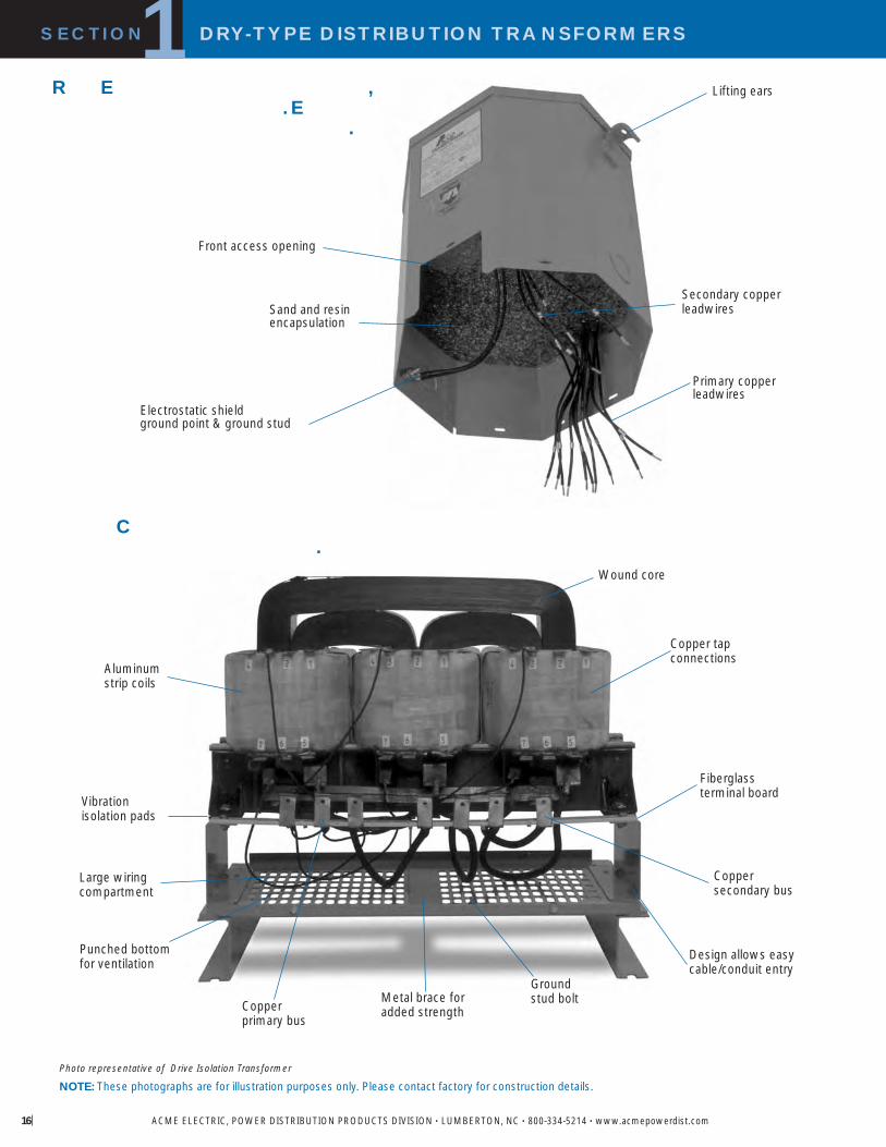
Aluminumstrip coils
Vibration isolation pads
Design allows easycable/conduit entry
Metal brace foradded strength
Coppersecondary bus
Punched bottomfor ventilation
Groundstud boltCopper
primary bus
Fiberglassterminal board
Copper tapconnections
Wound core
NOTE: These photographs are for illustration purposes only. Please contact factory for construction details.
Lifting ears
Sand and resinencapsulation
Primary copperleadwires
Front access opening
Secondary copperleadwires
Electrostatic shieldground point & ground stud
C .
R E , . E
.
Large wiringcompartment
Photo representative of Drive Isolation Transformer

SELECTION CHARTS SINGLE PHASE
��Suitable for 50/60 Hz. ��Wall mounting brackets are available for these sizes, refer to page 157.
240 X 480 PRIMARY VOLTS 120/240 SECONDARY VOLTS FOUR WINDINGS 1 , 60 Hz
316 STAINLESS STEEL240 X 480 PRIMARY VOLTS 120/240 SECONDARY VOLTS FOUR WINDINGS 1 , 60 Hz
GROUP I 316SS
GROUP I
APPRO DIMENSIONS APPRO T PE MTG EATHER DKVA CATALOG NO I C SHIP EIGHT KNOCKOUTS SHIELD D F
HEIGHT IDTH DEPTH L K F F I C P N B P 146
� .05 1 53004 6.41 16.3 3.14 8.0 3.05 7.7 4 1.8 0.875 2.2 1
� .10 1 53005 7.16 18.2 3.89 9.9 3.67 9.3 5 2.3 0.875 2.2 1
� .15 1 53006 7.16 18.2 3.89 9.9 3.67 9.3 7 3.2 0.875 2.2 1
� .25 2 53007 8.68 22.0 4.08 10.4 3.88 9.9 10 4.5 0.50 0.75 1.3 1.9 2
� .50 2 53008 9.06 23.0 4.37 11.1 4.20 10.7 15 6.8 0.50 0.75 1.3 1.9 2
� .75 2 53009 9.68 24.6 4.75 12.1 4.50 11.4 19 8.6 0.50 0.75 1.3 1.9 2
1.00 2 53010 10.50 26.7 5.50 14.0 5.13 13.0 24 10.9 0.50 0.75 1.3 1.9 2
1.50 2 53011 11.62 29.5 5.50 14.0 5.13 13.0 30 13.6 0.50 0.75 1.3 1.9 2
2.00 2 53012 13.00 33.0 5.50 14.0 5.13 13.0 38 17.2 0.50 0.75 1.3 1.9 2
3.00 2 53013 11.50 29.2 10.31 26.2 7.13 18.1 55 24.9 0.75 1.25 1.9 3.2 2
3.00 2 53013 4 11.50 29.2 10.31 26.2 7.13 18.1 55 24.9 0.75 1.25 1.9 3.2 3
5.00 2 53014 14.38 36.5 10.31 26.2 7.13 18.1 75 34.0 0.75 1.25 1.9 3.2 2
5.00 2 53014 4 14.38 36.5 10.31 26.2 7.13 18.1 75 34.0 0.75 1.25 1.9 3.2 3
7.50 2 53515 3 15.19 38.6 13.50 34.3 10.84 27.5 115 52.2 0.75 1.25 1.9 3.2 4
10.00 2 53516 3 15.19 38.6 13.50 34.3 10.84 27.5 125 56.7 0.75 1.25 1.9 3.2 4
15.00 2 53517 3 16.94 43.0 14.12 35.9 11.59 29.4 170 77.1 1.00 1.50 2.5 3.8 4
25.00 2 53518 3 18.44 46.8 16.13 41.0 13.34 33.9 250 113.0 1.00 1.50 2.5 3.8 4
37.50 2 53019 3 25.50 64.8 24.39 61.9 19.37 49.2 280 127.0 � 1 5
50.00 2 53020 3 25.50 64.8 24.39 61.9 19.37 49.2 350 158.8 � 1 5
75.00 2 53021 3 35.47 90.1 31.90 81.0 26.88 68.3 430 195.0 3 5
100.00 2 53022 3 41.52 105.5 32.90 83.6 29.87 75.9 525 238.0 4 5
167.00 1 53023 3 45.60 115.8 39.50 100.3 35.50 90.2 1050 476.3 5 5
250.00 2 53024 3 45.60 115.8 39.50 100.3 35.50 90.2 1440 653.2 5 5
APPRO DIMENSIONS APPRO T PE MTG EATHER DKVA CATALOG NO I C SHIP EIGHT KNOCKOUTS SHIELD D F
HEIGHT IDTH DEPTH L K F F I C P N B P 146
0.25 2 53007 8.68 22.0 4.08 10.4 3.88 9.9 10 4.5 2
0.50 2 53008 9.06 23.0 4.37 11.1 4.20 10.7 15 6.8 2
0.75 2 53009 9.68 24.6 4.75 12.1 4.50 11.4 19 8.6 2
1.00 2 53010 10.50 26.7 5.50 14.0 5.13 13.0 24 10.9 2
1.50 2 53011 11.62 29.5 5.50 14.0 5.13 13.0 30 13.6 2
2.00 2 53012 13.00 33.0 5.50 14.0 5.13 13.0 38 17.2 2
3.00 2 53013 11.50 29.2 10.31 26.2 7.13 18.1 55 24.9 3
5.00 2 53014 14.38 36.5 10.31 26.2 7.13 18.1 75 34.0 3
7.50 2 53515 15.19 38.6 13.50 34.3 10.84 27.5 115 52.2 4
10.00 2 53516 15.19 38.6 13.50 34.3 10.84 27.5 125 56.7 4
15.00 2 53517 16.94 43.0 14.12 35.9 11.59 29.4 170 77.1 4
25.00 2 53518 18.44 46.8 16.13 41.0 13.34 33.9 250 113.0 4
SECTION DRY-TYPE DISTRIBUTION TRANSFORMERS1
ACME ELECTRIC, POWER DISTRIBUTION PRODUCTS DIVISION • LUMBERTON, NC • 800-334-5214 • www.acmepowerdist.com
NEW

18
SECTION DRY-TYPE DISTRIBUTION TRANSFORMERS1
ACME ELECTRIC, POWER DISTRIBUTION PRODUCTS DIVISION • LUMBERTON, NC • 800-334-5214 • www.acmepowerdist.com
� Suitable for 50/60 Hz.�Wall mounting brackets are available for these sizes, refer to page 157.
120 X 240 PRIMARY VOLTS — 120/240 SECONDARY VOLTS — FOUR WINDINGS — 1Ø, 60 HzGROUP III
NON-VENTILATED TRANSFORMERS — 240 X 480 PRIMARY VOLTS — 120/240 SECONDARY VOLTS — FOUR WINDINGS — 1Ø, 60 Hz
GROUP II
240 X 480 PRIMARY VOLTS — COPPER WINDINGS — 120/240 SECONDARY VOLTS — FOUR WINDINGS — 1Ø, 60 HzGROUP IA
APPROX. DIMENSIONS APPROX. TYPE MTG. WEATHER Wiring Diagrams &KVA CATALOG NO. Inches (Cm.) SHIP WEIGHT W – Wall KNOCKOUTS SHIELD Design Figures
HEIGHT WIDTH DEPTH Lbs. (Kg.) F – Floor Inches (Cm.) P/N Begin on Page 146
7.50 53515 3 15.19 38.6 13.50 34.3 10.84 27.5 100 45.4 0.75 1.25 1.9 3.2 4
10.00 53516 3 15.19 38.6 13.50 34.3 10.84 27.5 120 54.4 0.75 1.25 1.9 3.2 4
15.00 53517 3 16.94 43.0 14.12 35.9 11.59 29.4 160 72.6 1.00 1.50 2.5 3.8 4
25.00 53518 3 18.44 46.8 16.13 41.0 13.34 33.9 250 113.0 1.00 1.50 2.5 3.8 4
37.50 53019 3 25.50 64.8 24.39 61.9 19.37 49.2 295 133.8 � 1 5
50.00 53020 3 25.50 64.8 24.39 61.9 19.37 49.2 378 172.0 � 1 5
75.00 53021 3 35.47 90.1 31.90 81.0 26.88 68.3 468 212.3 3 5
100.00 53022 3 41.52 105.5 32.90 83.6 29.87 75.9 768 348.4 4 5
APPROX. DIMENSIONS APPROX. TYPE MTG. WEATHER Wiring Diagrams &KVA CATALOG NO. Inches (Cm.) SHIP WEIGHT W – Wall KNOCKOUTS SHIELD Design Figures
HEIGHT WIDTH DEPTH Lbs. (Kg.) F – Floor Inches (Cm.) P/N Begin on Page 146
37.50 2 53019 3 35.47 90.1 31.90 81.0 26.90 68.3 430 195.0 � 5
50.00 2 53020 3 35.47 90.1 31.90 81.0 26.90 68.3 430 195.0 � 5
75.00 2 53021 3 35.47 90.1 31.90 81.0 26.90 68.3 525 238.0 5
100.00 1 53022 3 42.00 106.7 40.00 101.6 30.00 76.2 775 352.0 5
APPROX. DIMENSIONS APPROX. TYPE MTG. WEATHER Wiring Diagrams &KVA CATALOG NO. Inches (Cm.) SHIP WEIGHT W – Wall KNOCKOUTS SHIELD Design Figures
HEIGHT WIDTH DEPTH Lbs. (Kg.) F – Floor Inches (Cm.) P/N Begin on Page 146
1.0 3 53040 10.50 26.7 5.50 14.0 5.13 13.0 24 10.9 0.50 0.75 1.3 1.9 13
1.5 3 53041 11.62 29.5 5.50 14.0 5.13 13.0 30 13.6 0.50 0.75 1.3 1.9 13
2.0 3 53042 13.00 33.0 5.50 14.0 5.13 13.0 38 17.2 0.50 0.75 1.3 1.9 13
3.0 3 53043 11.50 29.2 10.31 26.2 7.13 18.1 55 24.9 0.75 1.25 1.9 3.2 13
5.0 3 53044 14.38 36.5 10.31 26.2 7.13 18.1 75 34.0 0.75 1.25 1.9 3.2 13
7.5 3 53545 15.19 38.6 13.50 34.3 10.84 27.5 115 52.2 0.75 1.25 1.9 3.2 13
10.0 3 53546 15.19 38.6 13.50 34.3 10.84 27.5 125 56.7 0.75 1.25 1.9 3.2 13
15.0 3 53547 16.94 43.0 14.12 35.9 11.59 29.4 170 77.1 1.00 1.50 2.5 3.8 13
25.0 3 53548 18.44 46.8 16.13 41.0 13.34 33.9 250 113.0 1.00 1.50 2.5 3.8 13

208 PRIMARY VOLTS — 120/240 SECONDARY VOLTS — THREE WINDINGS — 1Ø, 60 Hz
600 PRIMARY VOLTS — 120/240 SECONDARY VOLTS — THREE WINDINGS — 1Ø, 60 HzGROUP IV
GROUP V
APPRO DIMENSIONS APPRO T PE MTG EATHER DKVA CATALOG NO I C SHIP EIGHT KNOCKOUTS SHIELD D F
HEIGHT IDTH DEPTH L K F F I C P N B P 146
� .05 1 53104 6.41 16.3 3.14 8.0 3.05 7.7 4 1.8 0.875 2.2 8
� .10 1 53105 7.16 18.2 3.89 9.9 3.67 9.3 5 2.3 0.875 2.2 8
� .15 1 53106 7.16 18.2 3.89 9.9 3.67 9.3 7 3.2 0.875 2.2 8
� .25 2 53107 8.68 22.0 4.08 10.4 3.88 9.9 10 4.5 0.50 0.75 1.3 1.9 9
� .50 2 53108 9.06 23.0 4.37 11.1 4.20 10.7 15 6.8 0.50 0.75 1.3 1.9 9
� .75 2 53109 9.68 24.6 4.75 12.1 4.50 11.4 19 8.6 0.50 0.75 1.3 1.9 9
1.00 2 53110 10.50 26.7 5.50 14.0 5.13 13.0 24 10.9 0.50 0.75 1.3 1.9 9
1.50 2 53111 11.62 29.5 5.50 14.0 5.13 13.0 30 13.6 0.50 0.75 1.3 1.9 9
2.00 2 53112 13.00 33.0 5.50 14.0 5.13 13.0 38 17.2 0.50 0.75 1.3 1.9 9
3.00 2 53113 1 11.50 29.2 10.31 26.2 7.13 18.1 55 24.9 0.75 1.25 1.9 3.2 10
5.00 2 53114 1 14.38 36.5 10.31 26.2 7.13 18.1 75 34.0 0.75 1.25 1.9 3.2 10
7.50 2 53615 1 15.19 38.6 13.50 34.3 10.84 27.5 115 52.2 0.75 1.25 1.9 3.2 10
10.00 2 53616 1 15.19 38.6 13.50 34.3 10.84 27.5 125 56.7 0.75 1.25 1.9 3.2 10
15.00 2 53617 1 16.94 43.0 14.12 35.9 11.59 29.4 170 77.1 1.00 1.50 2.5 3.8 10
25.00 2 53618 1 18.44 46.8 16.13 41.0 13.34 33.9 250 113.0 1.00 1.50 2.5 3.8 10
37.50 2 53119 3 25.50 64.8 24.40 62.0 19.40 49.3 275 125.0 � 1 11
50.00 2 53120 3 29.90 76.0 28.15 71.5 22.37 56.8 340 154.0 � 2 11
75.00 2 53121 3 35.47 90.1 31.90 81.0 26.88 68.3 420 191.0 3 11
100.00 2 53122 3 41.52 105.5 32.90 83.6 29.87 75.9 525 238.0 4 11
167.00 1 53123 3 45.60 115.8 39.50 100.3 35.50 90.2 700 318.0 5 11
��Suitable for 50/60 Hz. ��Wall mounting brackets are available for these sizes, refer to page 157.
SECTION DRY-TYPE DISTRIBUTION TRANSFORMERS1
ACME ELECTRIC, POWER DISTRIBUTION PRODUCTS DIVISION • LUMBERTON, NC • 800-334-5214 • www.acmepowerdist.com
APPRO DIMENSIONS APPRO T PE MTG EATHER DKVA CATALOG NO I C SHIP EIGHT KNOCKOUTS SHIELD D F
HEIGHT IDTH DEPTH L K F F I C P N B P 146
1.0 2 53140 1 10.50 26.7 5.50 14.0 5.13 13.0 24 10.9 0.50 0.75 1.3 1.9 6
1.5 2 53141 1 11.62 29.5 5.50 14.0 5.13 13.0 30 13.6 0.50 0.75 1.3 1.9 6
2.0 2 53142 1 13.00 33.0 5.50 14.0 5.13 13.0 38 17.2 0.50 0.75 1.3 1.9 6
3.0 2 53143 1 11.50 29.2 10.31 26.2 7.13 18.1 55 24.9 0.75 1.25 1.9 3.2 6
5.0 2 53144 1 14.38 36.5 10.31 26.2 7.13 18.1 75 34.0 0.75 1.25 1.9 3.2 6
7.5 2 53645 1 15.19 38.6 13.50 34.3 10.84 27.5 115 52.2 0.75 1.25 1.9 3.2 6
10.0 2 53646 1 15.19 38.6 13.50 34.3 10.84 27.5 125 56.7 0.75 1.25 1.9 3.2 6
15.0 2 53647 1 16.94 43.0 14.12 35.9 11.59 29.4 170 77.1 1.00 1.50 2.5 3.8 6
25.0 2 53648 1 18.44 46.8 16.13 41.0 13.34 33.9 250 113.0 1.00 1.50 2.5 3.8 6
37.5 2 53649 1 25.48 64.7 24.39 62.0 19.37 49.2 257 117.0 � / 1 58
50.0 2 53650 3 25.48 64.7 24.39 62.0 19.37 49.2 340 154.2 � / 1 17
75.0 2 53651 3 35.40 89.9 31.90 81.0 26.88 68.2 420 190.5 � / 3 17NEW

20
SECTION DRY-TYPE DISTRIBUTION TRANSFORMERS1
ACME ELECTRIC, POWER DISTRIBUTION PRODUCTS DIVISION • LUMBERTON, NC • 800-334-5214 • www.acmepowerdist.com
AUTO-TRANSFORMERS240 PRIMARY VOLTS — 120/240 SECONDARY VOLTS — 1Ø, 60 Hz
GROUP VIII
120/208/240/277 PRIMARY VOLTS –– 120/240 SECONDARY VOLTS –– 1Ø, 60 Hz GROUP VII
277 PRIMARY VOLTS — 120/240 SECONDARY VOLTS — THREE WINDINGS — 1Ø, 60 HzGROUP VI
APPROX. DIMENSIONS APPROX. TYPE MTG. WEATHER Wiring Diagrams &KVA CATALOG NO. Inches (Cm.) SHIP WEIGHT W – Wall KNOCKOUTS SHIELD Design Figures
HEIGHT WIDTH DEPTH Lbs. (Kg.) F – Floor Inches (Cm.) P/N Begin on Page 146
1.0 2 53060 9.06 23.0 4.37 11.1 4.20 10.7 15 6.8 0.50 0.75 1.3 1.9 12
1.5 2 53061 9.68 24.6 4.50 11.4 4.51 11.5 19 8.6 0.50 0.75 1.3 1.9 12
2.0 2 53062 10.50 26.7 5.50 14.0 5.13 13.0 24 10.9 0.50 0.75 1.3 1.9 12
3.0 2 53063 11.62 29.5 5.50 14.0 5.13 13.0 30 13.6 0.50 0.75 1.3 1.9 12
5.0 2 53064 13.00 33.0 5.50 14.0 5.13 13.0 38 17.2 0.50 0.75 1.3 1.9 12
7.5 2 53065 11.50 29.2 10.31 26.2 7.13 18.1 55 24.9 0.75 1.25 1.9 3.2 12
10.0 2 53066 15.19 38.6 13.50 34.3 10.84 27.5 115 52.2 0.75 1.25 1.9 3.2 12
15.0 2 53067 15.19 38.6 13.50 34.3 10.84 27.5 115 52.2 0.75 1.25 1.9 3.2 12
APPROX. DIMENSIONS APPROX. TYPE MTG. WEATHER Wiring Diagrams &KVA CATALOG NO. Inches (Cm.) SHIP WEIGHT W – Wall KNOCKOUTS SHIELD Design Figures
HEIGHT WIDTH DEPTH Lbs. (Kg.) F – Floor Inches (Cm.) P/N Begin on Page 146
1.0 2 53170 1 10.50 26.7 5.50 14.0 5.13 13.0 24 10.9 0.50 0.75 1.3 1.9 7
1.5 2 53171 1 11.62 29.5 5.50 14.0 5.13 13.0 30 13.6 0.50 0.75 1.3 1.9 7
2.0 2 53172 1 13.00 33.0 5.50 14.0 5.13 13.0 38 17.2 0.50 0.75 1.3 1.9 7
3.0 2 53173 1 11.50 29.2 10.31 26.2 7.13 18.1 55 24.9 0.75 1.25 1.9 3.2 7
5.0 2 53174 1 14.38 36.5 10.31 26.2 7.13 18.1 75 34.0 0.75 1.25 1.9 3.2 7
7.5 2 53675 1 15.19 38.6 13.50 34.3 10.84 27.5 115 52.2 0.75 1.25 1.9 3.2 7
10.0 2 53676 1 15.19 38.6 13.50 34.3 10.84 27.5 125 56.7 0.75 1.25 1.9 3.2 7
15.0 2 53677 1 16.94 43.0 14.12 35.9 11.59 29.4 170 77.1 1.00 1.50 2.5 3.8 7
25.0 2 53678 1 18.44 46.8 16.13 41.0 13.34 33.9 250 113.0 1.00 1.50 2.5 3.8 7
APPROX. DIMENSIONS APPROX. TYPE MTG. WEATHER Wiring Diagrams &KVA CATALOG NO. Inches (Cm.) SHIP WEIGHT W – Wall KNOCKOUTS SHIELD Design Figures
HEIGHT WIDTH DEPTH Lbs. (Kg.) F – Floor Inches (Cm.) P/N Begin on Page 146
1.0 2 79740 10.50 26.7 5.50 14.0 5.13 13.0 23 10.4 0.50 0.75 1.3 1.9 23
1.5 2 79741 11.62 29.5 5.50 14.0 5.13 13.0 30 13.6 0.50 0.75 1.3 1.9 23
2.0 2 79742 13.00 33.0 5.50 14.0 5.13 13.0 37 16.8 0.50 0.75 1.3 1.9 23
3.0 2 79743 11.50 29.2 10.31 26.2 7.13 18.1 55 24.9 0.75 1.25 1.9 3.2 23
5.0 2 79744 14.38 36.5 10.31 26.2 7.13 18.1 75 34.0 0.75 1.25 1.9 3.2 23
7.5 2 79745 15.19 38.6 13.50 34.3 10.84 27.5 105 47.6 0.75 1.25 1.9 3.2 63
10.0 2 79746 15.19 38.6 13.50 34.3 10.84 27.5 124 56.2 0.75 1.25 1.9 3.2 63
15.0 2 79747 16.94 43.0 14.12 35.9 11.59 29.4 171 77.6 1.00 1.50 2.5 3.8 63
25.0 2 79748 18.44 46.8 16.13 41.0 13.34 33.9 261 118.4 1.00 1.50 2.5 3.8 63

EXPORT MODEL�190/200/208/220 x 380/400/416/440 PRIMARY VOLTS 110/220 SECONDARY VOLTS 1 , 50/60 Hz
GROUP XI
* CE Marked
EXPORT MODEL190/200/208/220 X 380/400/416/440 PRIMARY VOLTS120/240 SECONDARY VOLTS 1 , 50/60 Hz
GROUP IX
EXPORT MODEL�190/208/220/240 x 380/416/440/480 PRIMARY VOLTS 120/240 SECONDARY VOLTS 1 , 50/60 Hz
GROUP X
* CE Marked
* CE Marked
�Wall mounting brackets are available for these sizes, refer to page 157.�Maximum exciting current 5% at 50 Hz.
APPRO DIMENSIONS APPRO T PE MTG EATHER DKVA CATALOG NO I C SHIP EIGHT KNOCKOUTS SHIELD D F
HEIGHT IDTH DEPTH L K F F I C P N B P 146
1.0 2 17437 10.50 26.7 5.50 14.0 5.13 13.0 24 10.9 0.50 0.75 1.3 1.9 14
2.0 2 17439 13.00 33.0 5.50 14.0 5.13 13.0 38 17.2 0.50 0.75 1.3 1.9 14
3.0 2 49873 11.50 29.2 10.31 26.2 7.13 18.1 55 24.9 0.75 1.25 1.9 3.2 14
5.0 2 52520 14.38 36.5 10.31 26.2 7.13 18.1 75 34.0 0.75 1.25 1.9 3.2 14
7.5 2 52794 15.19 38.6 13.50 34.3 10.84 27.5 115 52.2 0.75 1.25 1.9 3.2 14
10.0 2 52795 15.19 38.6 13.50 34.3 10.84 27.5 125 56.7 0.75 1.25 1.9 3.2 14
15.0 2 52796 16.94 43.0 14.12 35.9 11.59 29.4 170 77.1 1.00 1.50 2.5 3.8 14
25.0 2 52797 18.44 46.8 16.13 41.0 13.34 33.9 300 136.0 1.00 1.50 2.5 3.8 14
37.5 2 69218 � 25.48 16.5 24.39 62.0 19.37 49.2 285 129.0 1 15
50.0 2 69219 � 29.41 74.7 28.15 71.5 22.37 56.8 380 172.0 2 15
75.0 2 69220 � 35.47 91.2 31.90 81.0 26.88 68.3 445 201.8 3 15
100.0 2 69221 � 41.52 90.1 32.90 83.6 29.87 75.9 525 238.0 4 15
APPRO DIMENSIONS APPRO T PE MTG EATHER DKVA CATALOG NO I C SHIP EIGHT KNOCKOUTS SHIELD D F
HEIGHT IDTH DEPTH L K F F I C P N B P 146
1.0 2 79260 10.50 26.7 5.50 14.0 5.13 13.0 24 10.9 0.50 0.75 1.3 1.9 64
2.0 2 79261 13.00 33.0 5.50 14.0 5.13 13.0 38 17.2 0.50 0.75 1.3 1.9 64
3.0 2 79262 11.50 29.2 10.31 26.2 7.13 18.1 55 24.9 0.75 1.25 1.9 3.2 64
5.0 2 79263 14.38 36.5 10.31 26.2 7.13 18.1 75 34.0 0.75 1.25 1.9 3.2 64
7.5 2 79264 15.19 38.6 13.50 34.3 10.84 27.5 115 52.2 0.75 1.25 1.9 3.2 64
10.0 2 79265 15.19 38.6 13.50 34.3 10.84 27.5 125 56.7 0.75 1.25 1.9 3.2 64
15.0 2 79266 16.94 43.0 14.12 35.9 11.59 29.4 170 77.1 1.00 1.50 2.5 3.8 64
25.0 2 79267 18.44 46.8 16.13 41.0 13.34 33.9 300 136.1 1.00 1.50 2.5 3.8 64
SECTION DRY-TYPE DISTRIBUTION TRANSFORMERS1
ACME ELECTRIC, POWER DISTRIBUTION PRODUCTS DIVISION • LUMBERTON, NC • 800-334-5214 • www.acmepowerdist.com
APPRO DIMENSIONS APPRO T PE MTG EATHER DKVA CATALOG NO I C SHIP EIGHT KNOCKOUTS SHIELD D F
HEIGHT IDTH DEPTH L K F F I C P N B P 146
1.0 2 79300 10.50 26.7 5.50 14.0 5.13 13.0 24 10.9 0.50 0.75 1.3 1.9 65
2.0 2 79301 13.00 33.0 5.50 14.0 5.13 13.0 38 17.2 0.50 0.75 1.3 1.9 65
3.0 2 79302 11.50 29.2 10.31 26.2 7.13 18.1 55 24.9 0.75 1.25 1.9 3.2 65
5.0 2 79303 14.38 36.5 10.31 26.2 7.13 18.1 75 34.0 0.75 1.25 1.9 3.2 65
7.5 2 79304 15.19 38.6 13.50 34.3 10.84 27.5 115 52.2 0.75 1.25 1.9 3.2 65

22
SECTION DRY-TYPE DISTRIBUTION TRANSFORMERS1
ACME ELECTRIC, POWER DISTRIBUTION PRODUCTS DIVISION • LUMBERTON, NC • 800-334-5214 • www.acmepowerdist.com
208 DELTA PRIMARY VOLTS –– 480Y/277 SECONDARY VOLTS –– 3Ø, 60 Hz
240 DELTA PRIMARY VOLTS –– 208Y/120 SECONDARY VOLTS –– 3Ø, 60 Hz
SELECTION CHARTS THREE PHASE
GROUP A
GROUP B
�Wall mounting brackets are available for these sizes, refer to page 157.� Consult factory for wiring diagram.
277/480 PRIMARY VOLTS –– 208/277 SECONDARY VOLTS –– 1Ø, 60 Hz GROUP XII
APPROX. DIMENSIONS APPROX. TYPE MTG. WEATHER Wiring Diagrams &KVA CATALOG NO. Inches (Cm.) SHIP WEIGHT W – Wall KNOCKOUTS SHIELD Design Figures
HEIGHT WIDTH DEPTH Lbs. (Kg.) F – Floor Inches (Cm.) P/N Begin on Page 146
15.0 3 79367 1 18.86 48.0 20.30 51.6 9.03 22.9 245 111.0 � 48
30.0 2 79368 4 25.50 64.8 24.40 62.0 19.40 49.3 330 150.0 � 1 46
45.0 2 79369 4 25.50 64.8 24.40 62.0 19.40 49.3 400 181.0 � 1 46
75.0 2 79370 4 29.41 74.7 28.15 71.5 22.37 56.8 530 240.0 � 2 46
112.5 2 79371 4 35.47 90.1 31.90 81.0 26.90 68.3 750 340.0 3 46
150.0 2 79372 4 41.52 105.5 32.90 83.6 29.87 75.9 950 430.9 4 46
225.0 2 79373 4 41.52 105.5 32.90 83.6 29.87 75.9 1200 544.0 4 46
300.0 3 79374 4 45.60 115.8 39.50 100.3 35.50 90.2 1550 703.0 5 46
500.0 2 79376 2 57.80 146.8 45.00 114.3 41.50 105.4 3500 1588.0 7 �
APPROX. DIMENSIONS APPROX. TYPE MTG. WEATHER Wiring Diagrams &KVA CATALOG NO. Inches (Cm.) SHIP WEIGHT W – Wall KNOCKOUTS SHIELD Design Figures
HEIGHT WIDTH DEPTH Lbs. (Kg.) F – Floor Inches (Cm.) P/N Begin on Page 146
9.0 2 53360 1 14.03 36.0 17.77 45.1 11.52 29.3 180 81.6 0.75 1.25 1.9 3.2 18
15.0 3 53361 1 18.86 48.0 20.30 51.6 9.03 23.0 250 113.0 � 18
30.0 3 53362 4 25.50 64.8 24.39 61.9 19.37 49.2 325 147.0 � 1 19
45.0 3 53363 4 25.50 64.8 24.39 61.9 19.37 49.2 350 158.8 � 1 19
75.0 3 53364 4 29.41 74.7 28.15 71.5 22.37 56.8 450 204.1 � 2 19
112.5 2 53365 4 35.47 90.1 31.90 81.0 26.88 68.3 696 294.8 3 19
150.0 2 53366 4 41.52 105.5 32.90 84.0 29.87 75.9 978 412.8 4 19
225.0 2 53367 4 41.52 105.5 32.90 84.0 29.87 75.9 1200 544.0 4 19
APPROX. DIMENSIONS APPROX. TYPE MTG. WEATHER Wiring Diagrams &KVA CATALOG NO. Inches (Cm.) SHIP WEIGHT W – Wall KNOCKOUTS SHIELD Design Figures
HEIGHT WIDTH DEPTH Lbs. (Kg.) F – Floor Inches (Cm.) P/N Begin on Page 146
0.25 12 250 8.68 22.0 4.08 10.4 3.88 9.9 12 5.4 0.50 0.75 1.3 1.9 78
0.50 12 500 9.06 23.0 4.37 11.1 4.20 10.7 19 8.6 0.50 0.75 1.3 1.9 78
1.00 12 1000 10.50 26.7 5.50 14.0 5.13 13.0 30 13.6 0.50 0.75 1.3 1.9 78
3.00 12 3000 11.50 29.2 10.31 26.2 7.13 18.1 58 26.3 0.75 1.25 1.9 3.2 78
5.00 12 5000 14.38 36.5 10.31 26.2 7.13 18.1 80 36.3 0.75 1.25 1.9 3.2 78
10.00 12 10000 15.19 38.6 13.50 34.3 10.84 27.5 125 56.7 0.75 1.25 1.9 3.2 79
15.00 12 15000 16.94 43.0 14.12 35.9 11.59 29.4 161 70.0 1.00 1.50 2.5 3.8 79
NEW
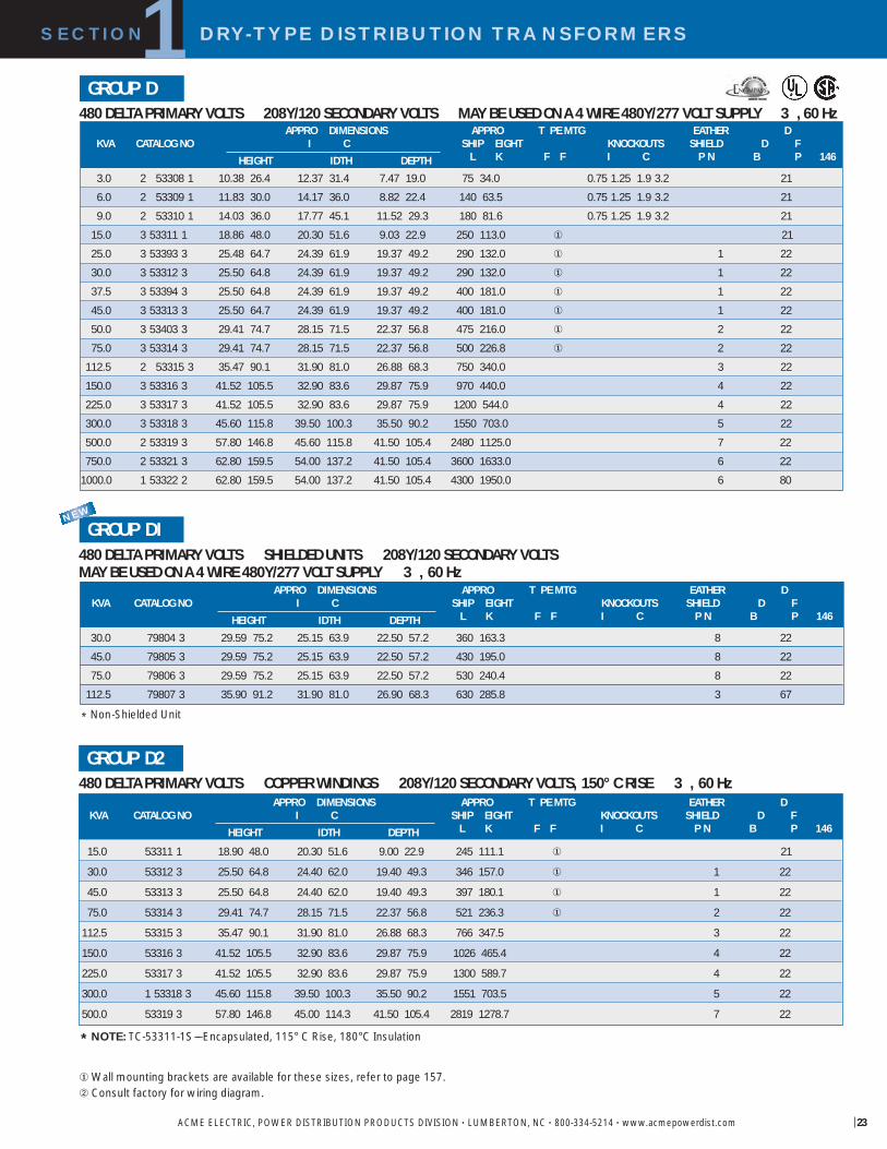
23
480 DELTA PRIMARY VOLTS 208Y/120 SECONDARY VOLTS MAY BE USED ON A 4 WIRE 480Y/277 VOLT SUPPLY 3 ,60 Hz GROUP D
�Wall mounting brackets are available for these sizes, refer to page 157.� Consult factory for wiring diagram.
480 DELTA PRIMARY VOLTS SHIELDED UNITS 208Y/120 SECONDARY VOLTS MAY BE USED ON A 4 WIRE 480Y/277 VOLT SUPPLY 3 , 60 Hz
GROUP DI
APPRO DIMENSIONS APPRO T PE MTG EATHER DKVA CATALOG NO I C SHIP EIGHT KNOCKOUTS SHIELD D F
HEIGHT IDTH DEPTH L K F F I C P N B P 146
30.0 79804 3 29.59 75.2 25.15 63.9 22.50 57.2 360 163.3 8 22
45.0 79805 3 29.59 75.2 25.15 63.9 22.50 57.2 430 195.0 8 22
75.0 79806 3 29.59 75.2 25.15 63.9 22.50 57.2 530 240.4 8 22
112.5 79807 3 35.90 91.2 31.90 81.0 26.90 68.3 630 285.8 3 67
SECTION DRY-TYPE DISTRIBUTION TRANSFORMERS1
ACME ELECTRIC, POWER DISTRIBUTION PRODUCTS DIVISION • LUMBERTON, NC • 800-334-5214 • www.acmepowerdist.com
480 DELTA PRIMARY VOLTS COPPER WINDINGS 208Y/120 SECONDARY VOLTS, 150° C RISE 3 , 60 Hz GROUP D2
* NOTE: TC-53311-1S––Encapsulated, 115° C Rise, 180°C Insulation
APPRO DIMENSIONS APPRO T PE MTG EATHER DKVA CATALOG NO I C SHIP EIGHT KNOCKOUTS SHIELD D F
HEIGHT IDTH DEPTH L K F F I C P N B P 146
15.0 53311 1 18.90 48.0 20.30 51.6 9.00 22.9 245 111.1 � 21
30.0 53312 3 25.50 64.8 24.40 62.0 19.40 49.3 346 157.0 � 1 22
45.0 53313 3 25.50 64.8 24.40 62.0 19.40 49.3 397 180.1 � 1 22
75.0 53314 3 29.41 74.7 28.15 71.5 22.37 56.8 521 236.3 � 2 22
112.5 53315 3 35.47 90.1 31.90 81.0 26.88 68.3 766 347.5 3 22
150.0 53316 3 41.52 105.5 32.90 83.6 29.87 75.9 1026 465.4 4 22
225.0 53317 3 41.52 105.5 32.90 83.6 29.87 75.9 1300 589.7 4 22
300.0 1 53318 3 45.60 115.8 39.50 100.3 35.50 90.2 1551 703.5 5 22
500.0 53319 3 57.80 146.8 45.00 114.3 41.50 105.4 2819 1278.7 7 22
* Non-Shielded Unit
APPRO DIMENSIONS APPRO T PE MTG EATHER DKVA CATALOG NO I C SHIP EIGHT KNOCKOUTS SHIELD D F
HEIGHT IDTH DEPTH L K F F I C P N B P 146
3.0 2 53308 1 10.38 26.4 12.37 31.4 7.47 19.0 75 34.0 0.75 1.25 1.9 3.2 21
6.0 2 53309 1 11.83 30.0 14.17 36.0 8.82 22.4 140 63.5 0.75 1.25 1.9 3.2 21
9.0 2 53310 1 14.03 36.0 17.77 45.1 11.52 29.3 180 81.6 0.75 1.25 1.9 3.2 21
15.0 3 53311 1 18.86 48.0 20.30 51.6 9.03 22.9 250 113.0 � 21
25.0 3 53393 3 25.48 64.7 24.39 61.9 19.37 49.2 290 132.0 � 1 22
30.0 3 53312 3 25.50 64.8 24.39 61.9 19.37 49.2 290 132.0 � 1 22
37.5 3 53394 3 25.50 64.8 24.39 61.9 19.37 49.2 400 181.0 � 1 22
45.0 3 53313 3 25.50 64.7 24.39 61.9 19.37 49.2 400 181.0 � 1 22
50.0 3 53403 3 29.41 74.7 28.15 71.5 22.37 56.8 475 216.0 � 2 22
75.0 3 53314 3 29.41 74.7 28.15 71.5 22.37 56.8 500 226.8 � 2 22
112.5 2 53315 3 35.47 90.1 31.90 81.0 26.88 68.3 750 340.0 3 22
150.0 3 53316 3 41.52 105.5 32.90 83.6 29.87 75.9 970 440.0 4 22
225.0 3 53317 3 41.52 105.5 32.90 83.6 29.87 75.9 1200 544.0 4 22
300.0 3 53318 3 45.60 115.8 39.50 100.3 35.50 90.2 1550 703.0 5 22
500.0 2 53319 3 57.80 146.8 45.60 115.8 41.50 105.4 2480 1125.0 7 22
750.0 2 53321 3 62.80 159.5 54.00 137.2 41.50 105.4 3600 1633.0 6 22
1000.0 1 53322 2 62.80 159.5 54.00 137.2 41.50 105.4 4300 1950.0 6 80
NEW
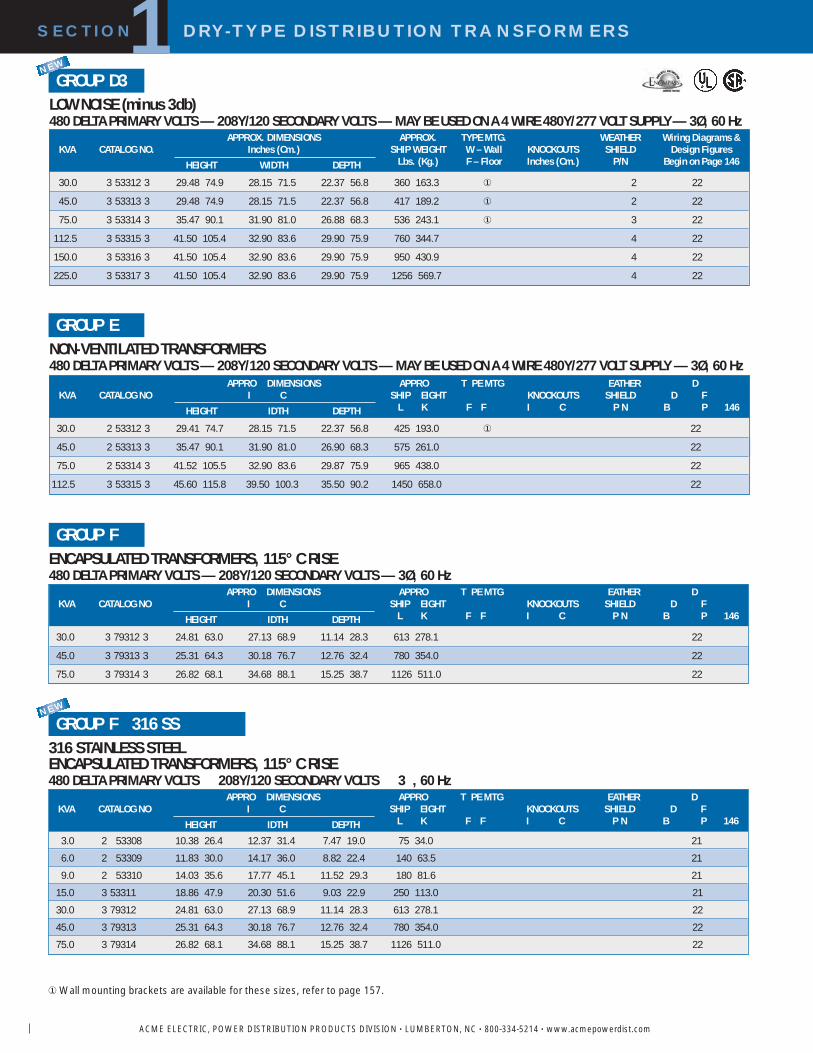
SECTION DRY-TYPE DISTRIBUTION TRANSFORMERS1
ACME ELECTRIC, POWER DISTRIBUTION PRODUCTS DIVISION • LUMBERTON, NC • 800-334-5214 • www.acmepowerdist.com
ENCAPSULATED TRANSFORMERS, 115° C RISE480 DELTA PRIMARY VOLTS — 208Y/120 SECONDARY VOLTS — 3Ø, 60 Hz
GROUP F
LOW NOISE (minus 3db)480 DELTA PRIMARY VOLTS — 208Y/120 SECONDARY VOLTS — MAY BE USED ON A 4 WIRE 480Y/277 VOLT SUPPLY— 3Ø, 60 Hz
GROUP D3
NON-VENTILATED TRANSFORMERS480 DELTA PRIMARY VOLTS — 208Y/120 SECONDARY VOLTS — MAY BE USED ON A 4 WIRE 480Y/277 VOLT SUPPLY — 3Ø, 60 Hz
GROUP E
APPROX. DIMENSIONS APPROX. TYPE MTG. WEATHER Wiring Diagrams &KVA CATALOG NO. Inches (Cm.) SHIP WEIGHT W – Wall KNOCKOUTS SHIELD Design Figures
HEIGHT WIDTH DEPTH Lbs. (Kg.) F – Floor Inches (Cm.) P/N Begin on Page 146
30.0 3 53312 3 29.48 74.9 28.15 71.5 22.37 56.8 360 163.3 � 2 22
45.0 3 53313 3 29.48 74.9 28.15 71.5 22.37 56.8 417 189.2 � 2 22
75.0 3 53314 3 35.47 90.1 31.90 81.0 26.88 68.3 536 243.1 � 3 22
112.5 3 53315 3 41.50 105.4 32.90 83.6 29.90 75.9 760 344.7 4 22
150.0 3 53316 3 41.50 105.4 32.90 83.6 29.90 75.9 950 430.9 4 22
225.0 3 53317 3 41.50 105.4 32.90 83.6 29.90 75.9 1256 569.7 4 22
APPRO DIMENSIONS APPRO T PE MTG EATHER DKVA CATALOG NO I C SHIP EIGHT KNOCKOUTS SHIELD D F
HEIGHT IDTH DEPTH L K F F I C P N B P 146
30.0 2 53312 3 29.41 74.7 28.15 71.5 22.37 56.8 425 193.0 � 22
45.0 2 53313 3 35.47 90.1 31.90 81.0 26.90 68.3 575 261.0 22
75.0 2 53314 3 41.52 105.5 32.90 83.6 29.87 75.9 965 438.0 22
112.5 3 53315 3 45.60 115.8 39.50 100.3 35.50 90.2 1450 658.0 22
APPRO DIMENSIONS APPRO T PE MTG EATHER DKVA CATALOG NO I C SHIP EIGHT KNOCKOUTS SHIELD D F
HEIGHT IDTH DEPTH L K F F I C P N B P 146
30.0 3 79312 3 24.81 63.0 27.13 68.9 11.14 28.3 613 278.1 22
45.0 3 79313 3 25.31 64.3 30.18 76.7 12.76 32.4 780 354.0 22
75.0 3 79314 3 26.82 68.1 34.68 88.1 15.25 38.7 1126 511.0 22
�Wall mounting brackets are available for these sizes, refer to page 157.
NEW
316 STAINLESS STEELENCAPSULATED TRANSFORMERS, 115° C RISE480 DELTA PRIMARY VOLTS 208Y/120 SECONDARY VOLTS 3 , 60 Hz
GROUP F 316 SS
APPRO DIMENSIONS APPRO T PE MTG EATHER DKVA CATALOG NO I C SHIP EIGHT KNOCKOUTS SHIELD D F
HEIGHT IDTH DEPTH L K F F I C P N B P 146
3.0 2 53308 10.38 26.4 12.37 31.4 7.47 19.0 75 34.0 21
6.0 2 53309 11.83 30.0 14.17 36.0 8.82 22.4 140 63.5 21
9.0 2 53310 14.03 35.6 17.77 45.1 11.52 29.3 180 81.6 21
15.0 3 53311 18.86 47.9 20.30 51.6 9.03 22.9 250 113.0 21
30.0 3 79312 24.81 63.0 27.13 68.9 11.14 28.3 613 278.1 22
45.0 3 79313 25.31 64.3 30.18 76.7 12.76 32.4 780 354.0 22
75.0 3 79314 26.82 68.1 34.68 88.1 15.25 38.7 1126 511.0 22
NEW

25
480 DELTA PRIMARY VOLTS –– 240 DELTA / 120 TAP SECONDARY VOLTS MAY BE USED ON A 4 WIRE 480Y/277 VOLT SUPPLY –– 3Ø, 60 Hz
GROUP G
480 DELTA PRIMARY VOLTS –– SHIELDED UNITS –– 240 DELTA / 120 TAP SECONDARY VOLTS MAY BE USED ON A 4 WIRE 480Y/277 VOLT SUPPLY –– 3Ø, 60 Hz
GROUP GI
APPROX. DIMENSIONS APPROX. TYPE MTG. WEATHER Wiring Diagrams &KVA CATALOG NO. Inches (Cm.) SHIP WEIGHT W – Wall KNOCKOUTS SHIELD Design Figures
HEIGHT WIDTH DEPTH Lbs. (Kg.) F – Floor Inches (Cm.) P/N Begin on Page 146
30.0 79844 3 29.59 75.2 25.15 63.9 22.50 57.2 365 165.6 8 26
45.0 79845 3 29.59 75.2 25.15 63.9 22.50 57.2 460 208.7 8 26
75.0 79846 3 29.59 75.2 25.15 63.9 22.50 57.2 530 240.4 8 26
112.5 79847 3 35.90 91.2 31.90 81.0 26.90 68.3 630 285.8 3 68
APPROX. DIMENSIONS APPROX. TYPE MTG. WEATHER Wiring Diagrams &KVA� CATALOG NO. Inches (Cm.) SHIP WEIGHT W – Wall KNOCKOUTS SHIELD Design Figures
HEIGHT WIDTH DEPTH Lbs. (Kg.) F – Floor Inches (Cm.) P/N Begin on Page 146
3.0 2 53328 1 10.38 26.4 12.37 31.4 7.47 19.0 75 34.0 0.75 1.25 1.9 3.2 25
6.0 2 53329 1 11.83 30.0 14.17 36.0 8.82 22.4 140 63.5 0.75 1.25 1.9 3.2 25
9.0 2 53340 1 14.03 36.0 17.77 45.1 11.52 29.3 180 81.6 0.75 1.25 1.9 3.2 25
15.0 3 53341 1 18.86 47.9 20.30 51.6 9.03 22.9 250 113.0 � 25
30.0 3 53342 3 25.50 64.8 24.39 61.9 19.37 49.2 325 147.0 � 1 26
45.0 3 53343 3 25.50 64.8 24.39 61.9 19.37 49.2 400 181.0 � 1 26
75.0 3 53344 3 29.41 74.7 28.15 71.5 22.37 56.8 500 226.8 � 2 26
112.5 2 53345 3 35.47 91.2 31.90 81.0 26.88 68.3 750 340.0 3 26
150.0 3 53346 3 41.52 105.5 32.90 83.6 29.87 75.9 1125 510.0 4 26
225.0 3 53347 3 41.52 105.5 32.90 83.6 29.87 75.9 1200 544.0 4 26
300.0 3 53348 3 45.60 115.8 39.50 100.3 35.50 90.2 1550 703.0 5 26
500.0 1 53349 3 62.00 157.5 54.00 137.2 42.00 106.7 2675 1213.0 3 27
750.0 2 53350 3 62.80 159.5 54.00 137.2 41.50 105.4 3408 1545.8 6 26
��Wall mounting brackets are available for these sizes, refer to page 157.� 3 KVA through 500 KVA provided with 120V lighting tap limited to 5% of nameplate rating.
SECTION DRY-TYPE DISTRIBUTION TRANSFORMERS1
ACME ELECTRIC, POWER DISTRIBUTION PRODUCTS DIVISION • LUMBERTON, NC • 800-334-5214 • www.acmepowerdist.com
LOW NOISE (minus 3 db)480 DELTA PRIMARY VOLTS –– 240 DELTA / 120 TAP SECONDARY VOLTS MAY BE USED ON A 4 WIRE 480Y/277 VOLT SUPPLY –– 3Ø, 60 Hz
GROUP G2NEW
APPROX. DIMENSIONS APPROX. TYPE MTG. WEATHER Wiring Diagrams &KVA CATALOG NO. Inches (Cm.) SHIP WEIGHT W – Wall KNOCKOUTS SHIELD Design Figures
HEIGHT WIDTH DEPTH Lbs. (Kg.) F – Floor Inches (Cm.) P/N Begin on Page 146
30.0 3 53342 3 29.48 74.9 28.15 71.5 22.37 56.8 360 163.3 � 2 26
45.0 3 53343 3 29.48 74.9 28.15 71.5 22.37 56.8 417 189.2 � 2 26
75.0 3 53344 3 35.47 90.1 31.90 81.0 26.88 68.3 536 243.1 � 3 26
112.5 3 53345 3 41.50 105.4 32.90 83.6 29.90 75.9 800 362.9 4 26
150.0 3 53346 3 41.50 105.4 32.90 83.6 29.90 75.9 950 430.9 4 26
225.0 3 53347 3 41.50 105.4 32.90 83.6 29.90 75.9 1256 569.7 4 26
* Non-Shielded Unit
NEW

6
ENCAPSULATED TRANSFORMERS, 115° C RISE600 DELTA PRIMARY VOLTS 208Y/120 SECONDARY VOLTS 3 , 60 Hz
GROUP K
APPRO DIMENSIONS APPRO T PE MTG EATHER DKVA CATALOG NO I C SHIP EIGHT KNOCKOUTS SHIELD D F
HEIGHT IDTH DEPTH L K F F I C P N B P 146
30.0 3 79334 3 24.81 63.0 27.13 68.9 11.14 28.3 613 278.1 29
45.0 3 79335 3 25.31 64.3 30.18 76.7 12.76 32.4 780 354.0 29
75.0 3 79336 3 26.82 68.1 34.68 88.1 15.25 38.7 1126 511.0 29
SECTION DRY-TYPE DISTRIBUTION TRANSFORMERS1
ACME ELECTRIC, POWER DISTRIBUTION PRODUCTS DIVISION • LUMBERTON, NC • 800-334-5214 • www.acmepowerdist.com
480 DELTA PRIMARY VOLTS 480Y/277 SECONDARY VOLTS MAY BE USED ON A 4 WIRE 480Y/277 VOLT SUPPLY 3 , 60 Hz
GROUP I
NON-VENTILATED TRANSFORMERS480 DELTA PRIMARY VOLTS 240 DELTA/ 120 TAP SECONDARY VOLTS MAY BE USED ON A 4 WIRE 480Y/277 VOLT SUPPLY 3 , 60 Hz
GROUP H
��Wall mounting brackets are available for these sizes, refer to page 157.
APPRO DIMENSIONS APPRO T PE MTG EATHER DKVA CATALOG NO I C SHIP EIGHT KNOCKOUTS SHIELD D F
HEIGHT IDTH DEPTH L K F F I C P N B P 146
30.0 3 53342 3 29.41 74.7 28.15 71.5 22.37 56.8 600 272.0 � 26
45.0 2 53343 3 35.47 90.1 31.90 81.0 26.88 68.3 750 340.0 26
75.0 2 53344 3 41.52 105.5 32.90 83.6 29.87 75.9 1125 510.0 26
112.5 3 53345 3 45.59 115.8 39.50 100.3 35.50 90.2 1150 522.0 26
APPRO DIMENSIONS APPRO T PE MTG EATHER DKVA CATALOG NO I C SHIP EIGHT KNOCKOUTS SHIELD D F
HEIGHT IDTH DEPTH L K F F I C P N B P 146
15.0 3 3500015 3 18.86 48.0 20.30 51.6 9.03 22.9 250 113.0 � 31
30.0 2 3500030 3 25.50 64.8 24.39 61.9 19.37 49.2 325 147.0 � 1 31
45.0 2 3500045 3 25.50 64.8 24.39 61.9 19.37 49.2 400 181.0 � 1 31
75.0 3 3500075 3 29.41 74.7 28.15 71.5 22.37 56.8 600 272.0 � 2 31
112.5 2 3500112 3 35.47 90.1 31.90 81.0 26.88 68.3 710 322.0 3 31
150.0 2 3500150 3 41.52 105.5 32.90 83.6 29.87 75.9 1155 524.0 4 31
225.0 2 3500225 3 41.52 105.5 32.90 83.6 29.87 75.9 1210 548.8 4 31
300.0 3 3500300 3 45.60 115.8 39.50 100.3 35.50 90.2 1600 726.0 5 31
500.0 3500500 3 62.00 157.5 54.00 137.2 42.00 106.7 2620 1188.0 3 32
600 DELTA PRIMARY VOLTS 208Y/120 SECONDARY VOLTS 3 , 60 Hz
GROUP J
APPRO DIMENSIONS APPRO T PE MTG EATHER DKVA CATALOG NO I C SHIP EIGHT KNOCKOUTS SHIELD D F
HEIGHT IDTH DEPTH L K F F I C P N B P 146
3.0 2 79330 1 10.38 26.4 12.37 31.4 7.47 19.0 75 34.0 0.75 1.25 1.9 3.2 28
6.0 2 79331 1 11.83 30.0 14.17 36.0 8.82 22.4 140 63.5 0.75 1.25 1.9 3.2 28
9.0 2 79332 1 14.03 36.0 17.77 45.1 11.52 29.3 180 81.6 0.75 1.25 1.9 3.2 28
15.0 3 79333 1 18.86 47.9 20.30 51.6 9.03 22.9 250 113.0 � 28
30.0 13102 3 25.50 64.8 24.39 61.9 19.37 49.2 325 147.0 � 1 29
45.0 13103 3 25.50 64.8 24.39 61.9 19.37 49.2 400 181.0 � 1 29
75.0 13104 3 29.41 74.7 28.15 71.5 22.37 56.8 600 272.0 � 2 29

27
SECTION DRY-TYPE DISTRIBUTION TRANSFORMERS1
ACME ELECTRIC, POWER DISTRIBUTION PRODUCTS DIVISION • LUMBERTON, NC • 800-334-5214 • www.acmepowerdist.com
600 DELTA PRIMARY VOLTS –– 480Y/277 SECONDARY VOLTS –– 3Ø, 60 Hz GROUP M
APPROX. DIMENSIONS APPROX. TYPE MTG. WEATHER Wiring Diagrams &KVA CATALOG NO. Inches (Cm.) SHIP WEIGHT W – Wall KNOCKOUTS SHIELD Design Figures
HEIGHT WIDTH DEPTH Lbs. (Kg.) F – Floor Inches (Cm.) P/N Begin on Page 146
3.0 2 79516 1 10.38 26.4 12.37 31.4 7.47 19.0 75 34.0 0.75 1.25 1.9 3.2 556.0 2 79517 1 11.83 30.0 14.17 36.0 8.82 22.4 140 63.5 0.75 1.25 1.9 3.2 559.0 2 79518 1 14.03 38.8 17.77 45.1 11.52 29.3 180 81.6 0.75 1.25 1.9 3.2 55
15.0 3 79519 1 18.86 47.9 20.30 51.6 9.03 22.9 250 113.0 � 5530.0 2 79520 3 29.41 74.7 28.15 71.5 22.37 56.8 400 181.0 � 2 5145.0 2 79521 3 29.41 74.7 28.15 71.5 22.37 56.8 425 193.0 � 2 5175.0 3 79522 3 29.41 74.7 28.15 71.5 22.37 56.8 700 318.0 � 2 51
112.5 2 79523 3 35.47 90.1 31.90 81.0 26.88 68.3 750 340.0 3 51150.0 2 79524 3 41.52 105.5 32.90 83.6 29.87 75.9 1125 510.0 4 51
208 DELTA PRIMARY VOLTS –– 208Y/120 SECONDARY VOLTS –– 3Ø, 60 Hz GROUP 0
APPROX. DIMENSIONS APPROX. TYPE MTG. WEATHER Wiring Diagrams &KVA CATALOG NO. Inches (Cm.) SHIP WEIGHT W – Wall KNOCKOUTS SHIELD Design Figures
HEIGHT WIDTH DEPTH Lbs. (Kg.) F – Floor Inches (Cm.) P/N Begin on Page 146
3.0 2 79268 1 10.38 26.4 12.37 31.4 7.47 19.0 75 34.0 0.75 1.25 1.9 3.2 606.0 2 79269 1 11.83 30.0 14.17 36.0 8.82 22.4 140 63.5 0.75 1.25 1.9 3.2 609.0 2 79270 1 14.03 36.0 17.77 45.1 11.52 29.3 180 81.6 0.75 1.25 1.9 3.2 60
15.0 3 79271 1 18.86 48.0 20.30 51.6 9.03 22.9 245 111.0 � 6030.0 2 79272 4 25.50 64.8 24.39 61.9 19.37 49.2 300 136.0 � 1 6145.0 2 79273 4 25.48 64.7 24.39 61.9 19.37 49.2 365 166.0 � 1 6175.0 2 79274 4 29.41 74.7 28.15 71.5 22.37 56.8 500 227.0 � 2 61
112.5 2 79275 4 35.47 90.1 31.90 81.0 26.88 68.3 700 318.0 3 61150.0 2 79276 4 41.52 105.5 32.90 83.6 29.87 75.9 970 440.0 4 61225.0 2 79277 4 41.52 105.5 32.90 83.6 29.87 75.9 1200 544.0 4 61
��Wall mounting brackets are available for these sizes, refer to page 157.
600 DELTA PRIMARY VOLTS –– 240 DELTA/120 TAP SECONDARY VOLTS –– 3Ø, 60 Hz GROUP P
APPROX. DIMENSIONS APPROX. TYPE MTG. WEATHER Wiring Diagrams &KVA CATALOG NO. Inches (Cm.) SHIP WEIGHT W – Wall KNOCKOUTS SHIELD Design Figures
HEIGHT WIDTH DEPTH Lbs. (Kg.) F – Floor Inches (Cm.) P/N Begin on Page 146
30.0 13142 3 25.50 64.8 24.39 61.9 19.37 49.2 299 135.6 � 1 69
45.0 13143 3 25.48 64.7 24.39 61.9 19.37 49.2 353 160.1 � 1 69
75.0 13144 3 29.41 74.7 28.15 71.5 22.37 56.8 463 210.0 � 2 69
GROUP Q240 DELTA PRIMARY VOLTS –– 480Y/277 SECONDARY VOLTS –– 3Ø, 60 Hz
APPROX. DIMENSIONS APPROX. TYPE MTG. WEATHER Wiring Diagrams &KVA CATALOG NO. Inches (Cm.) SHIP WEIGHT W – Wall KNOCKOUTS SHIELD Design Figures
HEIGHT WIDTH DEPTH Lbs. (Kg.) F – Floor Inches (Cm.) P/N Begin on Page 146
15.0 3 79693 1 18.86 48.0 20.30 51.6 9.03 22.9 245 111.1 � 70
30.0 2 79694 4 25.50 64.8 24.39 61.9 19.37 49.2 330 149.7 � 1 71
45.0 2 79695 4 25.48 64.7 24.39 61.9 19.37 49.2 380 172.4 � 1 71
75.0 2 79696 4 29.41 74.7 28.15 71.5 22.37 56.8 455 206.4 � 2 71
112.5 2 79697 4 35.47 90.1 31.90 81.0 26.88 68.3 687 311.6 3 71
150.0 2 79698 4 41.52 105.5 32.90 83.6 29.87 75.9 973 441.3 4 71

�Wall mounting brackets are available for these sizes, refer to page 157.
GROUP R380 DELTA PRIMARY VOLTS 208Y/120 SECONDARY VOLTS 3 , 60 Hz
APPRO DIMENSIONS APPRO T PE MTG EATHER DKVA CATALOG NO I C SHIP EIGHT KNOCKOUTS SHIELD D F
HEIGHT IDTH DEPTH L K F F I C P N B P 146
3.0 2 79708 4 10.38 26.4 12.37 31.4 7.47 19.0 75 34.0 0.75 1.25 1.9 3.2 33
6.0 2 79709 4 11.83 30.0 14.17 36.0 8.82 22.4 120 54.4 0.75 1.25 1.9 3.2 33
9.0 2 79710 4 14.03 36.0 17.77 45.1 11.52 29.3 175 79.4 0.75 1.25 1.9 3.2 33
15.0 3 79711 4 18.86 48.0 20.30 51.6 9.03 22.9 245 111.1 � 33
30.0 3 79712 3 25.50 64.8 24.39 61.9 19.37 49.2 295 133.8 � 1 72
45.0 3 79713 3 25.48 64.7 24.39 61.9 19.37 49.2 353 160.1 � 1 72
75.0 3 79714 3 29.41 74.7 28.15 71.5 22.37 56.8 457 207.3 � 2 72
112.5 2 79715 3 35.47 90.1 31.90 81.0 26.88 68.3 679 308.0 3 72
SECTION DRY-TYPE DISTRIBUTION TRANSFORMERS1
ACME ELECTRIC, POWER DISTRIBUTION PRODUCTS DIVISION • LUMBERTON, NC • 800-334-5214 • www.acmepowerdist.com
380 DELTA PRIMARY VOLTS 220Y/127 SECONDARY VOLTS 3 , 50/60 Hz GROUP T
APPRO DIMENSIONS APPRO T PE MTG EATHER DKVA CATALOG NO I C SHIP EIGHT KNOCKOUTS SHIELD D F
HEIGHT IDTH DEPTH L K F F I C P N B P 146
15.0 3 79551 1 20.80 52.8 20.90 53.1 10.20 25.9 435 197.3 24
30.0 2 79552 3 25.50 64.8 24.40 62.0 19.40 49.3 365 165.6 � 1 20
45.0 2 79553 3 29.41 74.7 28.15 71.5 22.37 56.8 468 212.3 � 2 20
75.0 2 79554 3 35.47 90.1 31.90 80.0 26.88 68.3 693 314.3 3 20
112.5 2 79555 3 41.52 105.5 32.90 83.6 29.87 75.9 970 440.0 4 20
150.0 2 79556 3 41.52 105.5 32.90 83.6 29.87 75.9 1100 499.0 4 20
225.0 3 79557 3 45.60 115.8 39.50 100.3 35.50 90.2 1600 725.7 5 20
GROUP U
APPRO DIMENSIONS APPRO T PE MTG EATHER DKVA CATALOG NO I C SHIP EIGHT KNOCKOUTS SHIELD D F
HEIGHT IDTH DEPTH L K F F I C P N B P 146
10.0 22010 5 18.90 48.0 20.30 51.6 9.00 22.9 245 111.1 � 73
15.0 22015 5 25.50 64.8 24.40 62.0 19.40 49.3 291 132.0 � 1 73
25.0 22025 5 25.50 64.8 24.40 62.0 19.40 49.3 375 170.1 � 1 73
50.0 22050 5 29.41 74.7 28.15 71.5 22.37 56.8 437 198.2 � 2 73
100.0 220100 5 41.52 105.5 32.90 83.6 29.87 75.9 725 328.9 4 73
200.0 220200 5 45.60 115.8 39.50 100.3 35.50 90.2 1025 464.9 5 73
250.0 220250 5 45.60 115.8 39.50 100.3 35.50 90.2 1600 725.8 5 73
300.0 220300 5 57.84 146.9 45.50 115.6 41.50 105.4 1700 771.12 7 73
500.0 220500 5 62.80 159.5 54.00 137.2 41.50 105.4 2418 1096.8 6 73
440 DELTA PRIMARY VOLTS 220Y/127 SECONDARY VOLTS 3 , 50/60 Hz

29
AUTO-TRANSFORMERS�600 PRIMARY VOLTS –– 480 SECONDARY VOLTS –– 3Ø, 60 Hz 480 PRIMARY VOLTS –– 380 SECONDARY VOLTS –– 3Ø, 50/60 Hz ALTERNATE RATING
� Wall mounting brackets use PL-79911.� If used on unbalanced loads, these units should only be used on a 4 wire
system with the supply neutral connected to the transformer. If used on balanced loads, such as motor loads, then they may be used on a 3 wire system without a neutral or 4th wire.
� These units are encapsulated with a 115° C temperature rise.� These units are ventilated with 150° C temperature rise. Wall mounting brackets use PL-79912.
190/200/208/220/240 DELTA PRIMARY VOLTS –– 400Y/231 SECONDARY VOLTS –– 3Ø, 60 Hz GROUP V
APPROX. DIMENSIONS APPROX. TYPE MTG. WEATHER Wiring Diagrams &KVA CATALOG NO. Inches (Cm.) SHIP WEIGHT W – Wall KNOCKOUTS SHIELD Design Figures
HEIGHT WIDTH DEPTH Lbs. (Kg.) F – Floor Inches (Cm.) P/N Begin on Page 146
15.0 3 79083 18.86 47.9 20.30 51.6 9.03 22.9 300 136.1 � 75
20.0 2 79084 29.90 75.9 28.15 71.5 22.37 56.8 500 226.8 2 74
30.0 2 79085 29.90 75.9 28.15 71.5 22.37 56.8 511 231.8 2 74
45.0 2 79087 25.50 64.8 24.39 62.0 19.37 49.2 540 244.9 1 74
75.0 2 79088 35.90 91.2 31.90 81.0 26.88 68.3 703 318.9 3 74
400 DELTA PRIMARY VOLTS –– 240 DELTA/120 SECONDARY VOLTS –– 3Ø, 60 Hz GROUP W
APPROX. DIMENSIONS APPROX. TYPE MTG. WEATHER Wiring Diagrams &KVA CATALOG NO. Inches (Cm.) SHIP WEIGHT W – Wall KNOCKOUTS SHIELD Design Figures
HEIGHT WIDTH DEPTH Lbs. (Kg.) F – Floor Inches (Cm.) P/N Begin on Page 146
15.0 3 79068 1 18.86 47.9 20.30 51.6 9.03 22.9 250 113.4 � / 76
30.0 3 79069 3 25.48 64.7 24.39 62.0 19.37 49.2 300 136.1 1 77
45.0 3 79070 3 25.48 64.7 24.39 62.0 19.37 49.2 365 165.6 1 77
75.0 3 79071 3 29.40 74.7 28.15 71.5 22.37 56.8 475 215.5 2 77
KVA APPROX. DIMENSIONS APPROX. TYPE MTG. WEATHER Wiring Diagrams &600 Pri. 480 Pri. CATALOG NO. Inches (Cm.) SHIP WEIGHT W – Wall KNOCKOUTS SHIELD Design Figures480V Sec. 380 Sec. HEIGHT WIDTH DEPTH Lbs. (Kg.) F – Floor Inches (Cm.) P/N Begin on Page 146
15.0 12.0 2 52703 1� 15.21 38.6 19.25 48.9 7.37 18.7 104 47.2 56
30.0 24.0 2 52705 1� 15.21 38.6 19.25 48.9 7.37 18.7 152 68.9 56
45.0 36.0 2 52707 1� 15.21 38.6 19.25 48.9 7.37 18.7 156 70.8 56
75.0 60.0 3 52710 1� 18.86 47.9 20.30 51.6 9.03 22.9 300 136.1 � 56
112.5 90.0 2 52712 1� 25.50 64.8 24.40 62.0 19.40 49.3 325 147.0 1 57
150.0 120.0 2 52713 1� 25.50 64.8 24.40 62.0 19.40 49.3 350 158.8 1 57
225.0 180.0 2 52715 1� 29.41 74.7 28.15 71.5 22.37 56.8 600 272.0 2 57
300.0 240.0 2 52717 1� 29.41 74.7 28.15 71.5 22.37 56.8 650 294.8 2 57
450.0 360.0 2 52718 1� 35.47 90.1 31.90 81.0 26.88 68.3 750 340.0 3 57
500.0 400.0 2 52719 1� 35.47 90.1 31.90 81.0 26.88 68.3 790 358.3 3 57
SECTION DRY-TYPE DISTRIBUTION TRANSFORMERS1
ACME ELECTRIC, POWER DISTRIBUTION PRODUCTS DIVISION • LUMBERTON, NC • 800-334-5214 • www.acmepowerdist.com
NEW
NEW

SECTION DRY-TYPE DISTRIBUTION TRANSFORMERS1
ACME ELECTRIC, POWER DISTRIBUTION PRODUCTS DIVISION • LUMBERTON, NC • 800-334-5214 • www.acmepowerdist.com
600 PRIMARY VOLTS 480 SECONDARY (open delta) VOLTS 3 , 60 Hz480 PRIMARY VOLTS 380 SECONDARY (open delta) VOLTS 3 , 50/60 Hz
� KVA capacity of three phase autotransformer bank, using two single phase, 60 Hz transformers connected open delta.
� Catalog No. is for 1 transformer, 2 units are required.��Can be reverse connected with no change in KVA.�� For transformer dimensions, refer to appropriate table in section 1, page 17.� For proper overcurrent protection, refer to Article 450-4 of N.E.C.
ABC
600OR480
VOLTS
480OR380
VOLTS
DIAGRAM SHOWS NO TAP UNITS ONLY
X
XX
X
H
HH
H
TRANS. #1
OPEN DELTA-AUTO
X
XX
X
H
HH
H
TRAN
S. #
2
ABC
THREE PHASE480 PRIMARY (open delta) VOLTS 240 SECONDARY (open delta) VOLTS 3 , 60 Hz
O = Fuse Location NEC 450-4, 1990.
T . P .
E A . R .
O = Fuse Location NEC 450-4, 1990.
Economical Auto ArrangementsUsing two single phase transformers
P 600V P S P 480V P S C � M SS 480V A A S 380V A A Q � N � F
KVA� KVA� B
8.0 7.70 9.60 6.5 7.80 9.60 2 2 53010 15
12.0 11.55 14.40 9.5 11.55 14.40 2 2 53011 15
17.0 16.33 20.41 13.5 16.33 20.41 2 2 53012 25
25.0 24.06 30.01 20.0 24.06 30.01 2 2 53013 4 30
43.0 41.38 51.70 34.0 41.38 51.70 2 2 53014 4 60
64.0 61.59 77.00 51.0 61.59 77.00 2 2 53515 3 80
86.0 82.76 103.44 68.0 82.76 103.44 2 2 53516 3 110
129.0 124.13 155.20 103.0 124.13 155.20 2 2 53517 3 175
216.0 207.85 259.80 172.0 207.85 259.80 2 2 53518 3 300
324.0 311.78 389.70 259.0 311.78 389.70 2 2 53019 3 400
433.0 416.67 520.83 346.0 416.67 520.83 2 2 53020 3 600
650.0 625.00 781.00 519.0 625.00 781.00 2 2 53021 3 800
865.0 833.00 1040.00 692.0 833.00 1051.00 2 2 53022 3 1200
1445.0 1391.00 1738.00 1156.0 1391.00 1756.00 2 1 53023 3 2000
2164.0 2083.00 2602.00 1731.0 2083.00 2629.00 2 1 53024 3 3000
P S M SKVA � Q � C N � F L F L F
A A B
3.0 2 2 53010 3.60 7.20 10
5.0 2 2 53011 6.00 12.00 10
6.0 2 2 53012 7.20 14.40 15
10.0 2 2 53013 4 12.00 24.00 15
17.0 2 2 53014 4 20.50 40.80 30
26.0 2 2 53515 3 31.50 63.00 40
34.0 2 2 53516 3 41.00 81.60 60
52.0 2 2 53517 3 63.00 125.00 80
86.0 2 2 53518 3 104.00 206.30 150
130.5 2 2 53019 3 157.00 314.00 200
173.0 2 2 53020 3 209.00 418.00 300
259.0 2 2 53021 3 312.00 623.00 400
346.0 2 2 53022 3 417.00 834.00 600
578.0 2 1 53023 3 696.00 1392.00 1000
865.0 2 1 53024 3 1041.00 2082.00 1600

31
PRIMARY (INPUT): 480 VOLTS SECONDARY (OUTPUT): 480Y/277 VOLTS3Ø, 3 WIRE ��50/60 Hz 3Ø, 4 WIRE
� Applicable for the above connection only.� Connection diagram (using 3 pieces of 1 phase, 60 hertz transformers connected zig-zag auto) for developing a neutral (4th wire) from a 3 phase,
3 wire supply.� For proper over-current protection, refer to the N.E.C. Article 450-5.� For transformer dimensions, refer to appropriate table in section 1, page 17.
E A . R .
NEUTRAL
B
POINTA,B OR C
TONEUTRALYIELDS277 V
SINGLEPHASE4 WIRE
C
A
B
C
A
INPUT480 V
3Ø3 WIRE
B CAXX
XX
X
H
H
H
H
X
XX
X
H
H
H
H
XX
X
H
H
H
H
COMMON TRIP DEVICE
NEUTRAL
TRANS. #3TRANS. #2TRANS. #1
See Footnote�
O = Fuse Location NEC 450-4, 1990. �
Use 3 Pieces Nameplate No. of Max. Continuous
of Available KVA Tfmr. Three Phase Amp. Load Per
Type No.� In For Each Tfmr. Required KVA Phase(277 Volts)
2 53010 1.0 3 10.80 12.50
2 53011 1.5 3 15.60 18.75
2 53012 2.0 3 20.70 25.00
2 53013 4 3.0 3 31.20 37.50
2 53014 4 5.0 3 51.90 62.50
2 53515 3 7.5 3 78.00 93.50
2 53516 3 10.0 3 103.80 125.00
2 53517 3 15.0 3 156.00 187.50
2 53518 3 25.0 3 259.50 312.00
2 53019 3 37.5 3 390.00 468.00
2 53020 3 50.0 3 519.00 625.00
2 53021 3 75.0 3 780.00 935.00
2 53022 3 100.0 3 1038.00 1250.00
1 53023 3 167.0 3 1734.00 2085.00
SECTION DRY-TYPE DISTRIBUTION TRANSFORMERS1
ACME ELECTRIC, POWER DISTRIBUTION PRODUCTS DIVISION • LUMBERTON, NC • 800-334-5214 • www.acmepowerdist.com
Auto Zig-Zag Grounding TransformersFor developing a neutral from a three phase, 3-wire supply

32
SECTION DRY-TYPE DISTRIBUTION TRANSFORMERS1
ACME ELECTRIC, POWER DISTRIBUTION PRODUCTS DIVISION • LUMBERTON, NC • 800-334-5214 • www.acmepowerdist.com
KE :O.D. O DISO IA TO A
Do You Have a Non-Standard Three Phase Voltage Application?Many non-standard voltage correction problems can be solvedby using standard off - the-shelf single phase transformers. The following is a list of such voltage combinations that can besupplied by the Power Distribution Products Division. Drawings
for these products can be downloaded from our website atwww.acmepowerdist.com. If you don t find the particularcombination you are looking for, contact our technical servicesdepartment for further assistance at 1-800-334-5214.
THREE PHASE
� Cannot Be Reverse Connected.
VOLTAGES AVAILABLE ACMEKVA
T PE OFDRA ING
INPUT OUTPUT RANGECIRCUIT
NO
208 208 /120 3 75 125879
208 208 /120 3 86 � 125895
208 240 /120 1.68 25.2 . . 700314
208 240 3 75 125880
208 416 /240 3 75 700598
208 416 /240 112.5 300 700591
208 /120 208 /120 3 75 125857
208 /120 374 /216 22.5 75 125883
208 /120 374 /216 112.5 750 102730
208 /120 480 /277 3 75 39881 2
240 208 /120 3 15 125855
240 208 /120 9 15 102723
240 208 /120 22.5 75 102722
240 208 /120 112.5 750 125856
240 208 /120 3 75 125858
240 240 3 75 125859
240 240 /138 10.3 258.75 � 125896
240 374 /216 22.5 75 125881
240 374 /216 112.5 750 125882
240 480 /277 3 75 39881 1
380 240 3 75 700592
380 240 112.5 300 700593
380 228 1.4 7.0 . . 35633
380 228 4.2 7.0 . . 125892
380 228 10.4 34.5 . . 125893
380 228 51 227 . . 125894
380 416 /240 3 75 700599
380 416 /240 112.5 300 700594
380 /220 240 3 75 700600
380 /220 240 112.5 300 700595
416 /240 440 3 75 700602
416 /240 440 112.5 300 700597
416 240 3 75 700601
416 240 112.5 300 700596
VOLTAGES AVAILABLE ACMEKVA
T PE OFDRA ING
INPUT OUTPUT RANGECIRCUIT
NO
416 /240 208 /120 3 15 700319
416 /240 208 /120 22.5 75 700322
480 240 /120 1.68 5.04 . . � 125849
480 240 /120 3.36 . . � 125850
480 240 /120 5.04 . . � 125851
480 240 /120 8.4 . . � 125852
480 240 /120 12.6 25.2 . . � 125853
480 240 /120 42 . . � 125854
480 240 /120 63 266 . . � 111702
480 240 1.68 8.4 . . 32817
480 240 5.04 8.4 . . 125872
480 240 12.6 42 . . 125873
480 240 63 420 . . 125874
480 416 /240 3 15 125875
480 416 /240 9 15 125876
480 416 /240 22.5 75 125877
480 416 /240 112.5 750 125878
480 394 /228 9 15 125884
480 394 /228 22.5 75 125885
480 394 /228 112.5 750 125886
600 208 /120 3 6 102758
600 208 /120 9 75 125863
600 208 /120 112.5 500 125864
600 240 3 6 125860
600 240 9 75 125861
600 240 112.5 500 125862
600 240 /120 1.68 2.52 . . � 125865
600 240 /120 3.36 . . � 125866
600 240 /120 5.04 25.2 . . � 125867
600 240 /120 42 . . � 125868
600 240 /120 63 168 . . � 125869
600 240 1.68 3.36 . . 33227
600 240 5.04 42 . . 125870
600 240 63 280 . . 125871

2SECTION OPTI-MISER® DRY-TYPE DISTRIBUTION TRANSFORMERS
ACME ELECTRIC, POWER DISTRIBUTION PRODUCTS DIVISION • LUMBERTON, NC • 800-334-5214 • www.acmepowerdist.com
These transformers on pages 33 - 40 have been replaced by Acme's Energy Efficient TP1transformers, please reference Sections 1& 3.

2SECTION OPTI-MISER® DRY-TYPE DISTRIBUTION TRANSFORMERS
ACME ELECTRIC, POWER DISTRIBUTION PRODUCTS DIVISION • LUMBERTON, NC • 800-334-5214 • www.acmepowerdist.com
These transformers on pages 33 - 40 have been replaced by Acme's Energy Efficient TP1transformers, please reference Sections 1& 3.

2SECTION OPTI-MISER® DRY-TYPE DISTRIBUTION TRANSFORMERS
ACME ELECTRIC, POWER DISTRIBUTION PRODUCTS DIVISION • LUMBERTON, NC • 800-334-5214 • www.acmepowerdist.com
These transformers on pages 33 - 40 have been replaced by Acme's Energy Efficient TP1transformers, please reference Sections 1& 3.

2SECTION OPTI-MISER® DRY-TYPE DISTRIBUTION TRANSFORMERS
ACME ELECTRIC, POWER DISTRIBUTION PRODUCTS DIVISION • LUMBERTON, NC • 800-334-5214 • www.acmepowerdist.com
These transformers on pages 33 - 40 have been replaced by Acme's Energy Efficient TP1transformers, please reference Sections 1& 3.

2SECTION OPTI-MISER® DRY-TYPE DISTRIBUTION TRANSFORMERS
ACME ELECTRIC, POWER DISTRIBUTION PRODUCTS DIVISION • LUMBERTON, NC • 800-334-5214 • www.acmepowerdist.com
These transformers on pages 33 - 40 have been replaced by Acme's Energy Efficient TP1transformers, please reference Sections 1& 3.

2SECTION OPTI-MISER® DRY-TYPE DISTRIBUTION TRANSFORMERS
ACME ELECTRIC, POWER DISTRIBUTION PRODUCTS DIVISION • LUMBERTON, NC • 800-334-5214 • www.acmepowerdist.com
These transformers on pages 33 - 40 have been replaced by Acme's Energy Efficient TP1transformers, please reference Sections 1& 3.
2SECTION OPTI-MISER® DRY-TYPE DISTRIBUTION TRANSFORMERS
ACME ELECTRIC, POWER DISTRIBUTION PRODUCTS DIVISION • LUMBERTON, NC • 800-334-5214 • www.acmepowerdist.com
These transformers on pages 33 - 40 have been replaced by Acme's Energy Efficient TP1transformers, please reference Sections 1& 3.

2SECTION OPTI-MISER® DRY-TYPE DISTRIBUTION TRANSFORMERS
ACME ELECTRIC, POWER DISTRIBUTION PRODUCTS DIVISION • LUMBERTON, NC • 800-334-5214 • www.acmepowerdist.com
These transformers on pages 33 - 40 have been replaced by Acme's Energy Efficient TP1transformers, please reference Sections 1& 3.

SECTION
NOTE: Dimension drawings, connection diagrams and accessories begin on page 146.
General Description & Features . . . . . . . . . . . .42
Selection Charts . . . . . . . . . . . . . . . . . . . . . . . .43
HARMONICMITIGATING
TRANSFORMERS
3
NON-LINEARLOAD ISOLATIONTRANSFORMERS
Special winding techniques minimi eedd current losses. A double si ed neutral handles e cessive neutral currents. UL Listed for K Factor Loads 4, 13 & 20.
General Description & Features . . . . . . . . .44-45
Selection Charts . . . . . . . . . . . . . . . . . . . . .46-51
Definition of Terms . . . . . . . . . . . . . . . . . . . . . .52
NEW

Harmonic Mitigating TransformersNEW
SECTION NON-LINEAR LOAD ISOLATION® & HARMONIC MITIGATING TRANSFORMERS3
ACME ELECTRIC, POWER DISTRIBUTION PRODUCTS DIVISION • LUMBERTON, NC • 800-334-5214 • www.acmepowerdist.com
Many of today s electronic devices are non-linear loadsgenerating high levels of harmonic currents that are thenfed back onto your distribution system. This waveform distortion results in overheating of motors and transformers,increased neutral currents and malfunction/damage toother equipment on the line.
Acme Electric introduces a line of harmonic mitigatingtransformers that combine the technologies shown in ournon-linear load (K-Factor) transformers. Where conventionalK-Factor transformers deal with harmonics, containing themwithin the transformer and preventing them from goingfurther upstream; harmonic mitigating transformers eliminateharmonics by pitting them against themselves. This technologynot only results in cleaner power but also provides the mostenergy efficient means to deal with harmonic problems.
Available in sizes ranging from 30 thru 225 KVA, with copperwindings and a variety of other design options and acces-sories, Acme harmonic mitigating transformers offer youreduced transformer heat, reduced voltage distortion due to3rd order harmonics, higher efficiency.
FEATURES� Unlike K-rated transformers, Harmonic Mitigating
transformers actually treat the triplen harmonics in the secondary winding
� Reduce supply voltage flat topping caused by non-linear loads
� Improve overall power factor of supply system
� Suitable for K-Factor loads
� Improved energy efficiency (Meet TP1 at K-1 load)
� Copper conductor construction
APPLICATIONS� Financial facilities
� Educational facilities
� TV Broadcast facilities
� Office buildings
� Hospitals
� Health care facilities
DIMENSIONAL DRAWING
D
H
W

SECTION NON-LINEAR LOAD ISOLATION® & HARMONIC MITIGATING TRANSFORMERS3
ACME ELECTRIC, POWER DISTRIBUTION PRODUCTS DIVISION • LUMBERTON, NC • 800-334-5214 • www.acmepowerdist.com
480 DELTA PRIMARY VOLTS 208Y/120 SECONDARY VOLTS
SELECTION CHARTS
HARMONIC MITIGATING TRANSFORMERSNEW
APPRO DIMENSIONS � APPRO T PE MTG EATHER DKVA CATALOG NO I C SHIP EIGHT SHIELD D F
HEIGHT IDTH DEPTH L K F F P N B P 146
30.0 53312 4 29.90 75.9 28.15 71.5 22.37 56.8 535 242.7 � 2 81
45.0 53313 4 29.90 75.9 28.15 71.5 22.37 56.8 600 272.2 � 2 81
75.0 53314 4 35.90 91.2 31.90 81.0 26.88 68.3 760 344.7 � 3 81
112.5 53315 4 41.52 105.5 32.90 83.6 29.88 75.9 1180 535.2 4 81
150.0 53316 4 41.52 105.5 32.90 83.6 29.88 75.9 1340 607.8 4 81
225.0 53317 4 41.52 105.5 32.90 83.6 29.88 75.9 1970 893.6 4 81
MITIGATING TRANSFORMER WIRING DIAGRAM
PRIMAR : 480 V DSECONDAR : 208 120 VTAPS: 2 2 1 2 ANFC 2 21 2 BNFC
123451234512345
X3X2X1
H1 H2 H3
X0
81
C CP P I S
V L T C L T504 1 2 3 1492 1 2 3 2480 1 2 3 3468 1 2 3 4456 1 2 3 5
S V208 1 2 3
1201 0
12 03 0
Harmonic Mitigating Transformers How do they work?
1. Acme utilizes special winding techniques and foil conductors in both its K-Factor and Harmonic Mitigatingtransformers to minimize the heating effects of harmoniccurrents.
2. The use of foil conductor increases the dielectric strengthof the insulation because one layer is only one turn. Foilalso eliminates the effects of axial forces, which can result in failure of wire wound transformers.
They consist of a Delta primary and a Zig-Zag secondary.The Zig-Zag secondary causes a phase shift in the triplenharmonics, which results in a canceling effect. This prevents
the triplen harmonic losses from being coupled back intothe primary and results in cooler operation and increasedenergy efficiency.
The Acme Advantages
Diagram Showing Delta Primary & Zig-Zag Secondary
(Zero degree angular displacement)
H2
H3
2
0
31
H1

SECTION NON-LINEAR LOAD ISOLATION® & HARMONIC MITIGATING TRANSFORMERS3
ACME ELECTRIC, POWER DISTRIBUTION PRODUCTS DIVISION • LUMBERTON, NC • 800-334-5214 • www.acmepowerdist.com44
Non- linear loads generate high levels of harmonic currents.When supplying power to these loads, a special transformerdesign is necessary.
Typical non-linear loads include desktop computers, AC variablespeed drives, HID lighting, electronic ballasts, inverters andwelders. Of these non-linear loads, the major source of harmoniccurrents is the switch mode power supply found in desktopcomputers, data processors and other office equipment.
Acme non-linear load isolation transformers use special windingtechniques to minimize eddy current losses generated byharmonic currents. A double-sized neutral conductor handles theexcessive neutral current found in non-linear load applications.
The amount of harmonics produced by a given load is representedby the term K factor. The larger the K factor, the moreharmonics are present. Linear loads have a K factor of 1; switchmode power supplies typically have a K factor as high as 20.
Acme non-linear load isolation transformers are shielded for cleanerpower and carry the Acme exclusive 10-year limited warranty.
Non-Linear Load Isolation® Transformers
* These ratings are to be used as a guide only. Theymay vary from one load equipment manufacturer toanother. A Spectrum Analysis is the best source.
N : Non-sinusoidal and non-linear are synonymousterms relating to the same transformer type.
K-Factor/Type of Load
K-1 Resistance heatingIncandescent lightingMotorsTransformers, control/distribution
K-4 WeldersInduction heatersHID lightingFluorescent lightingSolid state controls
K-13 Telecommunications equipmentBranch Circuits in classrooms
and health care facilities
K-20 Main frame computersVariable speed drivesBranch circuits with exclusive loads
of Data Processing equipmentDesktop computers
The following guide will help you select the propertransformer when the K-factor is unknown.*
FEATURES� Available in K-factors of 4, 13 and 20. Consult factory
for other K-factors.
� 150°C, 115°C and 80°C temperature rise units.
� 10-year limited warranty.
� UL Listed and CSA Certified.
� Available in 480V and 600V primary,15 through 600 KVA.
� Primary taps: (2) 2 1/2% ANFC, (4) 21/2 % BNFC.
� Aluminum and copper windings
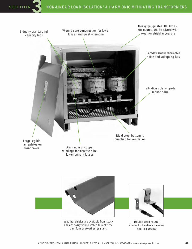
SECTION NON-LINEAR LOAD ISOLATION® & HARMONIC MITIGATING TRANSFORMERS3
ACME ELECTRIC, POWER DISTRIBUTION PRODUCTS DIVISION • LUMBERTON, NC • 800-334-5214 • www.acmepowerdist.com 45
Large legible nameplates on
front cover Aluminum or copper windings for increased life,
lower current losses
Industry standard fullcapacity taps
Wound core construction for lowerlosses and quiet operation
Heavy gauge steel UL Type 2enclosures, UL-3R Listed with
weather shield accessory
Faraday shield eliminatesnoise and voltage spikes
Rigid steel bottom ispunched for ventilation
Vibration isolation padsreduce noise
Double-sized neutral conductor handles excessive
neutral currents
Weather shields are available from stockand are easily field-installed to make the
transformer weather resistant.
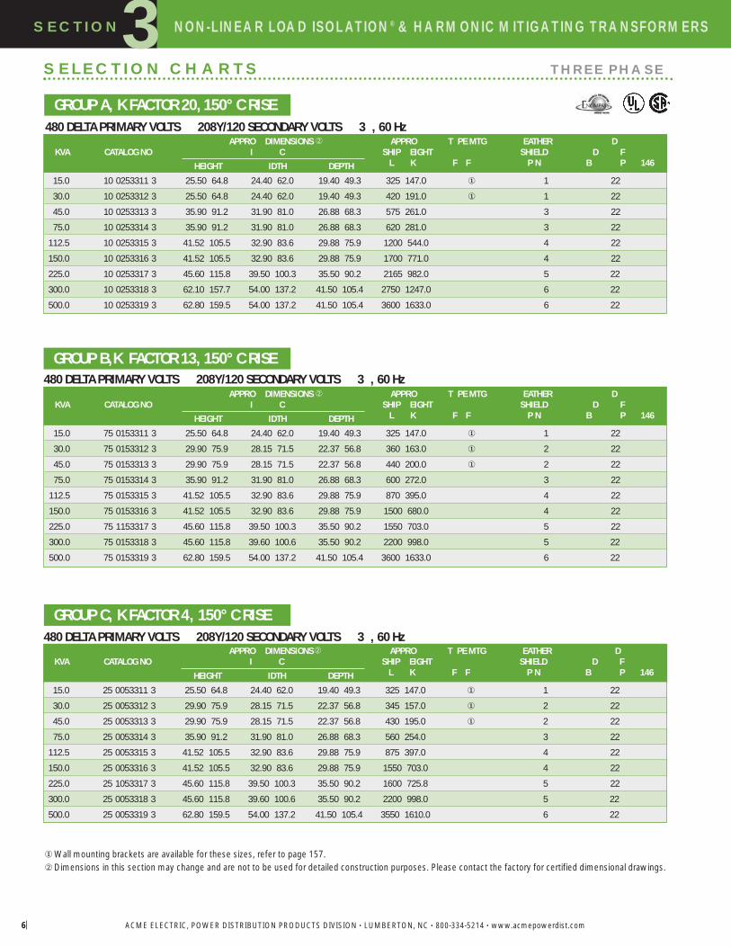
SECTION NON-LINEAR LOAD ISOLATION® & HARMONIC MITIGATING TRANSFORMERS3
ACME ELECTRIC, POWER DISTRIBUTION PRODUCTS DIVISION • LUMBERTON, NC • 800-334-5214 • www.acmepowerdist.com6
480 DELTA PRIMARY VOLTS 208Y/120 SECONDARY VOLTS 3 , 60 Hz
SELECTION CHARTS THREE PHASE
�Wall mounting brackets are available for these sizes, refer to page 157.�Dimensions in this section may change and are not to be used for detailed construction purposes. Please contact the factory for certified dimensional drawings.
480 DELTA PRIMARY VOLTS 208Y/120 SECONDARY VOLTS 3 , 60 Hz
GROUP A, K FACTOR 20,150° C RISE
GROUP B,K FACTOR 13, 150° C RISE
GROUP C, K FACTOR 4, 150° C RISE
APPRO DIMENSIONS � APPRO T PE MTG EATHER DKVA CATALOG NO I C SHIP EIGHT SHIELD D F
HEIGHT IDTH DEPTH L K F F P N B P 146
15.0 10 0253311 3 25.50 64.8 24.40 62.0 19.40 49.3 325 147.0 � 1 22
30.0 10 0253312 3 25.50 64.8 24.40 62.0 19.40 49.3 420 191.0 � 1 22
45.0 10 0253313 3 35.90 91.2 31.90 81.0 26.88 68.3 575 261.0 3 22
75.0 10 0253314 3 35.90 91.2 31.90 81.0 26.88 68.3 620 281.0 3 22
112.5 10 0253315 3 41.52 105.5 32.90 83.6 29.88 75.9 1200 544.0 4 22
150.0 10 0253316 3 41.52 105.5 32.90 83.6 29.88 75.9 1700 771.0 4 22
225.0 10 0253317 3 45.60 115.8 39.50 100.3 35.50 90.2 2165 982.0 5 22
300.0 10 0253318 3 62.10 157.7 54.00 137.2 41.50 105.4 2750 1247.0 6 22
500.0 10 0253319 3 62.80 159.5 54.00 137.2 41.50 105.4 3600 1633.0 6 22
480 DELTA PRIMARY VOLTS 208Y/120 SECONDARY VOLTS 3 , 60 HzAPPRO DIMENSIONS � APPRO T PE MTG EATHER D
KVA CATALOG NO I C SHIP EIGHT SHIELD D F
HEIGHT IDTH DEPTH L K F F P N B P 146
15.0 75 0153311 3 25.50 64.8 24.40 62.0 19.40 49.3 325 147.0 � 1 22
30.0 75 0153312 3 29.90 75.9 28.15 71.5 22.37 56.8 360 163.0 � 2 22
45.0 75 0153313 3 29.90 75.9 28.15 71.5 22.37 56.8 440 200.0 � 2 22
75.0 75 0153314 3 35.90 91.2 31.90 81.0 26.88 68.3 600 272.0 3 22
112.5 75 0153315 3 41.52 105.5 32.90 83.6 29.88 75.9 870 395.0 4 22
150.0 75 0153316 3 41.52 105.5 32.90 83.6 29.88 75.9 1500 680.0 4 22
225.0 75 1153317 3 45.60 115.8 39.50 100.3 35.50 90.2 1550 703.0 5 22
300.0 75 0153318 3 45.60 115.8 39.60 100.6 35.50 90.2 2200 998.0 5 22
500.0 75 0153319 3 62.80 159.5 54.00 137.2 41.50 105.4 3600 1633.0 6 22
APPRO DIMENSIONS� APPRO T PE MTG EATHER DKVA CATALOG NO I C SHIP EIGHT SHIELD D F
HEIGHT IDTH DEPTH L K F F P N B P 146
15.0 25 0053311 3 25.50 64.8 24.40 62.0 19.40 49.3 325 147.0 � 1 22
30.0 25 0053312 3 29.90 75.9 28.15 71.5 22.37 56.8 345 157.0 � 2 22
45.0 25 0053313 3 29.90 75.9 28.15 71.5 22.37 56.8 430 195.0 � 2 22
75.0 25 0053314 3 35.90 91.2 31.90 81.0 26.88 68.3 560 254.0 3 22
112.5 25 0053315 3 41.52 105.5 32.90 83.6 29.88 75.9 875 397.0 4 22
150.0 25 0053316 3 41.52 105.5 32.90 83.6 29.88 75.9 1550 703.0 4 22
225.0 25 1053317 3 45.60 115.8 39.50 100.3 35.50 90.2 1600 725.8 5 22
300.0 25 0053318 3 45.60 115.8 39.60 100.6 35.50 90.2 2200 998.0 5 22
500.0 25 0053319 3 62.80 159.5 54.00 137.2 41.50 105.4 3550 1610.0 6 22

SECTION NON-LINEAR LOAD ISOLATION® TRANSFORMERS3
ACME ELECTRIC, POWER DISTRIBUTION PRODUCTS DIVISION • LUMBERTON, NC • 800-334-5214 • www.acmepowerdist.com 47
NON-LINEAR LOAD ISOLATION® & HARMONIC MITIGATING TRANSFORMERS
480 DELTA PRIMARY VOLTS 208Y/120 SECONDARY VOLTS 3 , 60 Hz
480 DELTA PRIMARY VOLTS 208Y/120 SECONDARY VOLTS 3 , 60 Hz
480 DELTA PRIMARY VOLTS 208Y/120 SECONDARY VOLTS 3 , 60 Hz
�Wall mounting brackets are available for these sizes, refer to page 157.�Dimensions in this section may change and are not to be used for detailed construction purposes. Please contact the factory for certified dimensional drawings.
GROUP G, K FACTOR 20, 115° C RISE
GROUP H, K FACTOR 13, 115° C RISE
GROUP I, K FACTOR 4, 115° C RISE
APPRO DIMENSIONS � APPRO T PE MTG EATHER DKVA CATALOG NO I C SHIP EIGHT SHIELD D F
HEIGHT IDTH DEPTH L K F F P N B P 146
15.0 10 0253311 1 25.50 64.8 24.40 62.0 19.40 49.3 290 132.0 � 1 22
30.0 10 0253312 1 25.50 64.8 24.40 62.0 19.40 49.3 375 170.0 � 1 22
45.0 10 0253313 1 35.90 91.2 31.90 81.0 26.90 68.3 680 308.0 3 22
75.0 10 0253314 1 41.50 105.4 32.90 83.6 29.90 75.9 970 440.0 4 22
112.5 10 0253315 1 41.50 105.4 32.90 83.6 29.90 75.9 1140 517.0 4 22
150.0 10 1253316 1 45.60 115.8 39.50 100.3 35.50 90.2 1550 703.0 5 22
225.0 10 0253317 1 45.60 115.8 39.50 100.3 35.50 90.2 2225 1009.0 5 22
300.0 10 0253318 1 62.80 159.5 54.00 137.2 41.50 105.4 3600 1633.0 6 22
APPRO DIMENSIONS � APPRO T PE MTG EATHER DKVA CATALOG NO I C SHIP EIGHT SHIELD D F
HEIGHT IDTH DEPTH L K F F P N B P 146
15.0 75 0153311 1 25.50 64.8 24.40 62.0 19.40 49.3 325 147.0 � 1 22
30.0 75 0153312 1 29.90 75.9 28.20 71.6 22.40 56.9 400 181.0 � 2 22
45.0 75 0153313 1 35.90 91.2 31.90 81.0 26.90 68.3 575 261.0 3 22
75.0 75 0153314 1 35.90 91.2 31.90 81.0 26.90 68.3 750 340.0 3 22
112.5 75 0153315 1 41.50 105.4 32.90 83.6 29.90 75.9 1120 508.0 4 22
150.0 75 0153316 1 41.50 105.4 32.90 83.6 29.90 75.9 1200 544.0 4 22
225.0 75 0153317 1 45.60 115.8 39.50 100.3 35.50 90.2 2225 1009.0 5 22
300.0 75 0153318 1 62.80 159.5 54.00 137.2 41.50 105.4 3600 1633.0 6 22
APPRO DIMENSIONS � APPRO T PE MTG EATHER DKVA CATALOG NO I C SHIP EIGHT SHIELD D F
HEIGHT IDTH DEPTH L K F F P N B P 146
15.0 25 0053311 1 25.48 64.7 24.39 62.0 19.37 49.2 325 147.0 � 1 22
30.0 25 0053312 1 25.50 64.8 24.40 62.0 19.40 49.3 345 157.0 � 1 22
45.0 25 0053313 1 29.90 75.9 28.20 71.6 22.40 56.9 425 193.0 � 2 22
75.0 25 0053314 1 35.90 91.2 31.90 81.0 26.90 68.3 575 261.0 3 22
112.5 25 0053315 1 41.50 105.4 32.90 83.6 29.90 75.9 1125 510.0 4 22
150.0 25 0053316 1 41.50 105.4 32.90 83.6 29.90 75.9 1140 517.0 4 22
225.0 25 1053317 1 45.60 115.8 39.50 100.3 35.50 90.2 1550 703.0 5 22
300.0 25 0053318 1 45.60 115.8 39.50 100.3 35.50 90.2 2225 1009.0 5 22
500.0 25 0053319 1 62.80 159.5 54.00 137.2 41.50 105.4 3600 1633.0 6 22

SECTION NON-LINEAR LOAD ISOLATION® TRANSFORMERS3
ACME ELECTRIC, POWER DISTRIBUTION PRODUCTS DIVISION • LUMBERTON, NC • 800-334-5214 • www.acmepowerdist.com
NON-LINEAR LOAD ISOLATION® & HARMONIC MITIGATING TRANSFORMERS
480 DELTA PRIMARY VOLTS — 208Y/120 SECONDARY VOLTS — 3Ø, 60 Hz
480 DELTA PRIMARY VOLTS — 208Y/120 SECONDARY VOLTS — 3Ø, 60 Hz
480 DELTA PRIMARY VOLTS — 208Y/120 SECONDARY VOLTS — 3Ø, 60 Hz
�Wall mounting brackets are available for these sizes, refer to page 157.�Dimensions in this section may change and are not to be used for detailed construction purposes. Please contact the factory for certified dimensional drawings.�Consult factory for wiring diagrams.
GROUP J, K FACTOR 20, 80° C RISE
GROUP K, K FACTOR 13, 80° C RISE
GROUP L, K FACTOR 4, 80° C RISE
208 DELTA PRIMARY VOLTS — 208Y/120 SECONDARY VOLTS — 3Ø, 60 HzGROUP M, K FACTOR 13, 150° C RISE
APPROX. DIMENSIONS � APPROX. TYPE MTG. WEATHER Wiring Diagrams &KVA CATALOG NO. Inches (Cm.) SHIP WEIGHT W – Wall SHIELD Design Figures
HEIGHT WIDTH DEPTH Lbs. (Kg.) F – Floor P/N Begin on Page 146
30.0 10 0253312 8 35.41 89.9 31.90 81.0 26.87 68.2 575 261.0 3 2245.0 10 0253313 8 35.41 89.9 31.90 81.0 26.90 68.3 790 358.0 3 2275.0 10 0253314 8 41.50 105.4 32.90 83.6 29.90 75.9 1000 454.0 4 22
112.5 10 1253315 8 45.60 115.8 39.50 100.3 35.50 90.2 1550 703.0 5 22150.0 10 01253316 8 45.60 115.8 39.50 100.3 35.50 90.2 2225 1009.0 5 22225.0 10 0253317 8 62.80 159.5 54.00 137.2 41.50 105.4 3525 1599.0 6 22300.0 10 0253318 8 62.80 159.5 54.00 137.2 41.50 105.4 4300 1950.0 6 �
APPROX. DIMENSIONS � APPROX. TYPE MTG. WEATHER Wiring Diagrams &KVA CATALOG NO. Inches (Cm.) SHIP WEIGHT W – Wall SHIELD Design Figures
HEIGHT WIDTH DEPTH Lbs. (Kg.) F – Floor P/N Begin on Page 146
15.0 75 0153311 8 25.50 64.8 24.40 62.0 19.40 49.3 325 147.0 � 1 2230.0 75 0153312 8 35.90 91.2 31.90 81.0 26.90 68.3 575 261.0 3 2245.0 75 0153313 8 35.90 91.2 31.90 81.0 26.90 68.3 590 267.6 3 2275.0 75 0153314 8 41.50 105.4 32.90 83.6 29.90 75.9 970 440.0 4 22
112.5 75 0153315 8 41.50 105.4 32.90 83.6 29.90 75.9 1140 517.0 4 22150.0 75 0153316 8 45.60 115.8 39.50 100.3 35.50 90.2 2225 1009.0 5 22225.0 75 0153317 8 62.80 159.5 54.00 137.2 41.50 105.4 3525 1599.0 6 22300.0 75 0153318 8 62.80 159.5 54.00 137.2 41.50 105.4 3650 1655.6 6 22500.0 75 0153319 8 62.84 159.6 54.00 137.2 41.50 105.4 4300 1950.0 6 22
APPROX. DIMENSIONS � APPROX. TYPE MTG. WEATHER Wiring Diagrams &KVA CATALOG NO. Inches (Cm.) SHIP WEIGHT W – Wall SHIELD Design Figures
HEIGHT WIDTH DEPTH Lbs. (Kg.) F – Floor P/N Begin on Page 146
15.0 25 0053311 8 25.50 64.8 24.40 62.0 19.40 49.3 325 147.0 � 1 2230.0 25 0053312 8 25.48 64.7 24.40 62.0 19.37 49.2 425 193.0 2 2245.0 25 0053313 8 35.40 89.9 31.90 81.0 26.87 68.2 600 272.0 � 3 2275.0 25 0053314 8 41.52 105.5 32.90 83.6 29.87 75.9 970 440.0 4 22
112.5 25 0053315 8 41.50 105.4 32.90 83.6 29.90 75.9 1140 517.0 4 22150.0 25 1053316 8 49.59 126.0 39.50 100.3 35.50 90.2 1550 703.0 5 22225.0 25 0053317 8 49.59 126.0 39.50 100.3 35.50 90.2 2225 1009.0 5 22300.0 25 0053318 8 62.80 159.5 54.00 137.2 41.50 105.4 3525 1599.0 6 22500.0 25 0053319 8 62.80 159.5 54.00 137.2 41.50 105.4 3600 1633.0 6 22
APPROX. DIMENSIONS � APPROX. TYPE MTG. WEATHER Wiring Diagrams &KVA CATALOG NO. Inches (Cm.) SHIP WEIGHT W – Wall SHIELD Design Figures
HEIGHT WIDTH DEPTH Lbs. (Kg.) F – Floor P/N Begin on Page 146
15.0 75 0179271 4 25.50 64.8 24.90 62.0 19.37 49.2 320 145.1 � 1 6130.0 75 0179272 4 25.50 64.8 24.90 62.0 19.37 49.2 366 166.0 � 1 6145.0 75 0179273 4 29.40 74.7 28.15 71.5 22.37 56.8 522 236.8 � 2 6175.0 75 0179274 4 35.40 89.9 31.90 81.0 26.87 68.2 667 302.6 3 61
112.5 75 0179275 4 42.52 105.5 32.90 83.6 29.87 75.9 936 424.6 4 61150.0 75 0179276 4 42.52 105.5 32.90 83.6 29.87 75.9 1210 548.9 4 61

SECTION NON-LINEAR LOAD ISOLATION® TRANSFORMERS3
ACME ELECTRIC, POWER DISTRIBUTION PRODUCTS DIVISION • LUMBERTON, NC • 800-334-5214 • www.acmepowerdist.com 49
NON-LINEAR LOAD ISOLATION® & HARMONIC MITIGATING TRANSFORMERS
COPPER NON-LINEAR480 DELTA PRIMARY VOLTS 208Y/120 SECONDARY VOLTS 3 , 60 Hz
GROUP N, K FACTOR 20, 150° C RISE
COPPER NON-LINEAR480 DELTA PRIMARY VOLTS 208Y/120 SECONDARY VOLTS 3 , 60 Hz
GROUP O, K FACTOR 13, 150° C RISE
COPPER NON-LINEAR480 DELTA PRIMARY VOLTS 208Y/120 SECONDARY VOLTS 3 , 60 Hz
GROUP P, K FACTOR 4, 150° C RISE
� Wall mounting brackets are available for these sizes, refer to page 157.� Dimensions in this section may change and are not to be used for detailed construction purposes. Please contact the factory for certified dimensional drawings.
APPRO DIMENSIONS � APPRO T PE MTG EATHER DKVA CATALOG NO I C SHIP EIGHT SHIELD D F
HEIGHT IDTH DEPTH L K F F P N B P 146
30.0 10 0253312 3 25.48 64.7 24.39 62.0 19.40 49.3 365 165.6 � 1 22
45.0 10 0253313 3 25.48 64.7 24.39 91.9 19.40 49.3 445 202.0 � 1 22
75.0 10 0253314 3 29.40 74.4 28.15 71.5 22.40 56.9 656 298.0 2 22
112.5 10 0253315 3 35.40 89.9 31.90 81.0 26.70 67.8 910 413.0 3 22
150.0 10 0253316 3 41.52 105.5 32.90 83.6 29.90 75.9 1358 616.0 4 22
225.0 10 1253317 3 45.59 115.8 39.50 100.3 35.50 90.2 1770 803.0 5 22
300.0 10 0253318 3 62.80 159.5 54.00 137.2 41.50 105.4 4230 1918.7 6 22
APPRO DIMENSIONS � APPRO T PE MTG EATHER DKVA CATALOG NO I C SHIP EIGHT SHIELD D F
HEIGHT IDTH DEPTH L K F F P N B P 146
15.0 75 0153311 3 25.48 64.7 24.39 62.0 19.40 49.3 346 157.0 � 1 22
30.0 75 0153312 3 25.48 64.7 24.39 62.0 19.40 49.3 365 165.6 � 1 22
45.0 75 0153313 3 25.48 64.7 24.39 62.0 19.40 49.3 445 202.0 � 1 22
75.0 75 0153314 3 29.40 74.4 28.15 71.5 22.40 56.9 633 287.0 2 22
112.5 75 0153315 3 35.40 89.9 31.90 81.0 26.70 67.8 910 413.0 3 22
150.0 75 0153316 3 41.52 105.5 32.90 83.6 29.90 75.9 1358 616.0 4 22
225.0 75 1153317 3 45.59 115.8 39.50 100.3 35.50 90.2 1770 803.0 5 22
300.0 75 1153318 3 45.59 115.8 39.50 100.3 35.50 90.2 2301 1044.0 5 22
500.0 75 0153319 3 62.80 159.5 54.00 137.2 41.50 105.4 4230 1918.7 6 22
APPRO DIMENSIONS � APPRO T PE MTG EATHER DKVA CATALOG NO I C SHIP EIGHT SHIELD D F
HEIGHT IDTH DEPTH L K F F P N B P 146
15.0 25 0053311 3 25.48 64.7 24.39 62.0 19.40 49.3 346 157.0 � 1 22
30.0 25 0053312 3 25.48 64.7 24.39 62.0 19.40 49.3 365 165.6 � 1 22
45.0 25 0053313 3 25.48 64.7 24.39 62.0 19.40 49.3 445 202.0 � 1 22
75.0 25 0053314 3 29.40 74.4 28.15 71.5 22.40 56.9 633 287.0 2 22
112.5 25 0053315 3 35.40 89.9 31.90 81.0 26.90 68.3 892 405.0 3 22
150.0 25 0053316 3 41.52 105.5 32.90 83.6 29.90 75.9 1205 547.0 4 22
225.0 25 1053317 3 45.59 115.8 39.50 100.3 35.50 90.2 1554 705.0 5 22
300.0 25 1053318 3 45.59 115.8 39.50 100.3 35.50 90.2 1957 888.0 5 22
500.0 25 0053319 3 62.80 159.5 54.00 137.2 41.50 105.4 4230 1918.7 6 22
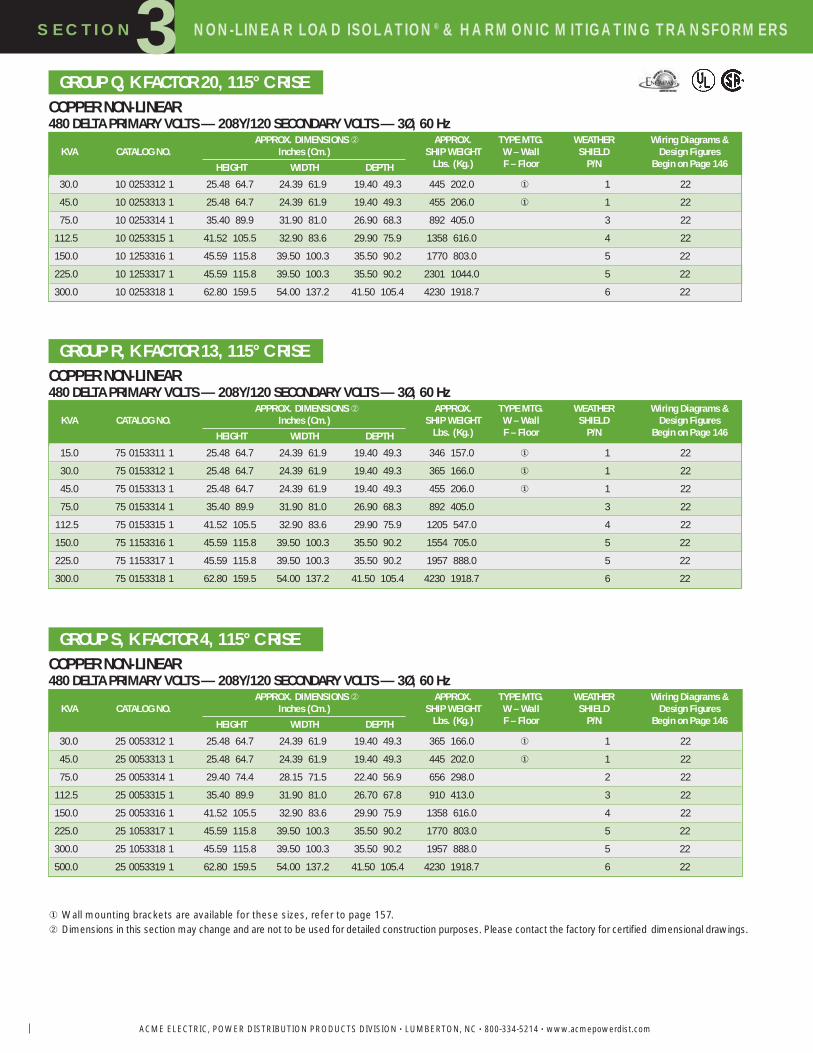
SECTION NON-LINEAR LOAD ISOLATION® TRANSFORMERS3
ACME ELECTRIC, POWER DISTRIBUTION PRODUCTS DIVISION • LUMBERTON, NC • 800-334-5214 • www.acmepowerdist.com
NON-LINEAR LOAD ISOLATION® & HARMONIC MITIGATING TRANSFORMERS
COPPER NON-LINEAR480 DELTA PRIMARY VOLTS — 208Y/120 SECONDARY VOLTS — 3Ø, 60 Hz
GROUP Q, K FACTOR 20, 115° C RISE
COPPER NON-LINEAR480 DELTA PRIMARY VOLTS — 208Y/120 SECONDARY VOLTS — 3Ø, 60 Hz
GROUP R, K FACTOR 13, 115° C RISE
GROUP S, K FACTOR 4, 115° C RISE
� Wall mounting brackets are available for these sizes, refer to page 157.� Dimensions in this section may change and are not to be used for detailed construction purposes. Please contact the factory for certified dimensional drawings.
APPROX. DIMENSIONS � APPROX. TYPE MTG. WEATHER Wiring Diagrams &KVA CATALOG NO. Inches (Cm.) SHIP WEIGHT W – Wall SHIELD Design Figures
HEIGHT WIDTH DEPTH Lbs. (Kg.) F – Floor P/N Begin on Page 146
30.0 10 0253312 1 25.48 64.7 24.39 61.9 19.40 49.3 445 202.0 � 1 22
45.0 10 0253313 1 25.48 64.7 24.39 61.9 19.40 49.3 455 206.0 � 1 22
75.0 10 0253314 1 35.40 89.9 31.90 81.0 26.90 68.3 892 405.0 3 22
112.5 10 0253315 1 41.52 105.5 32.90 83.6 29.90 75.9 1358 616.0 4 22
150.0 10 1253316 1 45.59 115.8 39.50 100.3 35.50 90.2 1770 803.0 5 22
225.0 10 1253317 1 45.59 115.8 39.50 100.3 35.50 90.2 2301 1044.0 5 22
300.0 10 0253318 1 62.80 159.5 54.00 137.2 41.50 105.4 4230 1918.7 6 22
APPROX. DIMENSIONS � APPROX. TYPE MTG. WEATHER Wiring Diagrams &KVA CATALOG NO. Inches (Cm.) SHIP WEIGHT W – Wall SHIELD Design Figures
HEIGHT WIDTH DEPTH Lbs. (Kg.) F – Floor P/N Begin on Page 146
15.0 75 0153311 1 25.48 64.7 24.39 61.9 19.40 49.3 346 157.0 � 1 22
30.0 75 0153312 1 25.48 64.7 24.39 61.9 19.40 49.3 365 166.0 � 1 22
45.0 75 0153313 1 25.48 64.7 24.39 61.9 19.40 49.3 455 206.0 � 1 22
75.0 75 0153314 1 35.40 89.9 31.90 81.0 26.90 68.3 892 405.0 3 22
112.5 75 0153315 1 41.52 105.5 32.90 83.6 29.90 75.9 1205 547.0 4 22
150.0 75 1153316 1 45.59 115.8 39.50 100.3 35.50 90.2 1554 705.0 5 22
225.0 75 1153317 1 45.59 115.8 39.50 100.3 35.50 90.2 1957 888.0 5 22
300.0 75 0153318 1 62.80 159.5 54.00 137.2 41.50 105.4 4230 1918.7 6 22
APPROX. DIMENSIONS � APPROX. TYPE MTG. WEATHER Wiring Diagrams &KVA CATALOG NO. Inches (Cm.) SHIP WEIGHT W – Wall SHIELD Design Figures
HEIGHT WIDTH DEPTH Lbs. (Kg.) F – Floor P/N Begin on Page 146
30.0 25 0053312 1 25.48 64.7 24.39 61.9 19.40 49.3 365 166.0 � 1 22
45.0 25 0053313 1 25.48 64.7 24.39 61.9 19.40 49.3 445 202.0 � 1 22
75.0 25 0053314 1 29.40 74.4 28.15 71.5 22.40 56.9 656 298.0 2 22
112.5 25 0053315 1 35.40 89.9 31.90 81.0 26.70 67.8 910 413.0 3 22
150.0 25 0053316 1 41.52 105.5 32.90 83.6 29.90 75.9 1358 616.0 4 22
225.0 25 1053317 1 45.59 115.8 39.50 100.3 35.50 90.2 1770 803.0 5 22
300.0 25 1053318 1 45.59 115.8 39.50 100.3 35.50 90.2 1957 888.0 5 22
500.0 25 0053319 1 62.80 159.5 54.00 137.2 41.50 105.4 4230 1918.7 6 22
COPPER NON-LINEAR480 DELTA PRIMARY VOLTS — 208Y/120 SECONDARY VOLTS — 3Ø, 60 Hz

SECTION NON-LINEAR LOAD ISOLATION® TRANSFORMERS3
ACME ELECTRIC, POWER DISTRIBUTION PRODUCTS DIVISION • LUMBERTON, NC • 800-334-5214 • www.acmepowerdist.com 51
NON-LINEAR LOAD ISOLATION® & HARMONIC MITIGATING TRANSFORMERS
COPPER NON-LINEAR480 DELTA PRIMARY VOLTS 208Y/120 SECONDARY VOLTS 3 , 60 Hz
GROUP T, K FACTOR 20, 80° C RISE
COPPER NON-LINEAR480 DELTA PRIMARY VOLTS 208Y/120 SECONDARY VOLTS 3 , 60 Hz
GROUP U, K FACTOR 13, 80° C RISE
COPPER NON-LINEAR480 DELTA PRIMARY VOLTS 208Y/120 SECONDARY VOLTS 3 , 60 Hz
GROUP V, K FACTOR 4, 80° C RISE
�Wall mounting brackets are available for these sizes, refer to page 157.�Dimensions in this section may change and are not to be used for detailed construction purposes. Please contact the factory for certified dimensional drawings.
APPRO DIMENSIONS � APPRO T PE MTG EATHER DKVA CATALOG NO I C SHIP EIGHT SHIELD D F
HEIGHT IDTH DEPTH L K F F P N B P 146
15.0 10 0253311 8 25.48 64.7 24.39 62.0 19.40 49.3 346 157.0 � 1 22
30.0 10 0253312 8 25.48 64.7 24.39 62.0 19.40 49.3 445 202.0 � 1 22
45.0 10 0253313 8 29.40 74.7 28.15 71.5 22.40 56.9 633 287.0 � 2 22
75.0 10 0253314 8 35.40 89.9 31.90 81.0 26.70 67.8 910 413.0 3 22
112.5 10 0253315 8 41.52 105.5 32.90 83.6 29.90 75.9 1358 616.0 4 22
150.0 10 1253316 8 45.59 115.8 39.50 100.3 35.50 90.2 1770 803.0 5 22
225.0 10 0253317 8 62.80 159.5 54.00 137.2 41.50 105.4 3525 1598.9 6 22
300.0 10 0253318 8 62.80 159.5 54.00 137.2 41.50 105.4 4230 1918.7 6 22
APPRO DIMENSIONS � APPRO T PE MTG EATHER DKVA CATALOG NO I C SHIP EIGHT SHIELD D F
HEIGHT IDTH DEPTH L K F F P N B P 146
15.0 25 0053311 8 25.48 64.7 24.39 62.0 19.40 49.3 346 157.0 � 1 22
30.0 25 0053312 8 25.48 64.7 24.39 62.0 19.40 49.3 445 202.0 � 1 22
45.0 25 0053313 8 29.40 74.4 28.15 71.5 22.40 56.9 633 287.0 � 2 22
75.0 25 0053314 8 35.40 89.9 31.90 81.0 26.90 68.3 892 405.0 3 22
112.5 25 0053315 8 41.52 105.5 32.90 83.6 29.90 75.9 1205 547.0 4 22
150.0 25 1053316 8 45.59 115.8 39.50 100.3 35.50 90.2 1554 705.0 5 22
225.0 25 1053317 8 45.59 115.8 39.50 100.3 35.50 90.2 2301 1044.0 5 22
300.0 25 0053318 8 62.80 159.4 54.00 137.2 41.50 105.4 4230 1918.7 6 22
NON-LINEAR LOAD ISOLATION WIRING DIAGRAMS (Refer to pgs 147-156)
NON-LINEAR LOAD ISOLATION DESIGN FIGURES (Refer to pg 146)
APPRO DIMENSIONS � APPRO T PE MTG EATHER DKVA CATALOG NO I C SHIP EIGHT SHIELD D F
HEIGHT IDTH DEPTH L K F F P N B P 146
15.0 75 0153311 8 25.48 64.7 24.39 62.0 19.40 49.3 346 157.0 � 1 22
30.0 75 0153312 8 25.48 64.7 24.39 62.0 19.40 49.3 445 202.0 � 1 22
45.0 75 0153313 8 29.40 74.7 28.15 71.5 22.40 56.9 633 287.0 � 2 22
75.0 75 0153314 8 35.40 89.9 31.90 81.0 26.70 67.8 910 413.0 3 22
112.5 75 0153315 8 41.52 105.5 32.90 83.6 29.90 75.9 1358 616.0 4 22
150.0 75 1153316 8 45.59 115.8 39.50 100.3 35.50 90.2 1770 803.0 5 22
225.0 75 1153317 8 45.59 115.8 39.50 100.3 35.50 90.2 2301 1044.0 5 22
300.0 75 0153318 8 62.80 159.5 54.00 137.2 41.50 105.4 4230 1918.7 6 22

SECTION NON-LINEAR LOAD ISOLATION® TRANSFORMERS3
ACME ELECTRIC, POWER DISTRIBUTION PRODUCTS DIVISION • LUMBERTON, NC • 800-334-5214 • www.acmepowerdist.com
NON-LINEAR LOAD ISOLATION® & HARMONIC MITIGATING TRANSFORMERS
1. Linear loadsLoads where the current waveform conforms to the waveformof the applied voltage. Or loads where a change in current isdirectly proportional to a change in applied voltage. For example:
• Resistance heating• Incandescent lighting• Water heater
2.Non-linear loadsLoads where the current waveform does not conform to thewaveform of the applied voltage. Or loads where a change incurrent is not proportional to a change in applied voltage.Examples are:
• Computer power supplies• Motor drives• Fluorescent lighting
Non-linear loads produce non-sinusoidal current or voltagewaveforms.
3.Sinusoidal current or voltageThis term refers to a periodic waveform that can be expressedas the sine of a linear function of time.
4.Non-linear currents or voltagesA waveform of current or voltage which cannot be expressedas the sine of a linear function of time. A non-linear load wouldresult in a non-sinusoidal current or voltage.
5.HarmonicA sinusoidal waveform with a frequency that is an integralmultiple of the fundamental 60 Hz frequency.
60 Hz Fundamental120 Hz 2nd Harmonic180 Hz 3rd Harmonic240 Hz 4th Harmonic
etc.
Current waveforms from non-linear loads appear distortedbecause the non-linear waveform is the result of addingharmonic components to the fundamental current.
6.Triplen harmonicsOdd multiples of the 3rd harmonic(3rd, 9th, 15th, 21st, etc.).
7. Harmonic distortionNon-linear distortion of a system characterized by the appearance in the output of harmoniccurrents (voltages) when the input is sinusoidal.
8.Voltage harmonic distortion (VHD)Voltage harmonic distortion is distortion caused by harmoniccurrents flowing through the system impedance. The utilitypower system has relatively low system impedance, and theVHD is very low. But, VHD on the distribution power systemcan be significant due to its relatively high system impedance.
9.Total harmonic distortion (THD)The square root of the sum of the squares of all harmonic currents present in the load excluding the 60 Hz fundamental.It is usually expressed as a percent of the fundamental.
10. Root mean squared current (or voltage) RMS1: The vector sum of the fundamental current and the totalharmonic distortion. 2: Square root of the sum of the squared value of thefundamental current and the squared value of the totalharmonic distortion.
11. Eddy currentsCurrents flowing in a conducting material in the presence of atime varying magnetic field. These currents are in addition tothe current drawn by the load.
12. Eddy current lossesPower dissipated due to eddy currents. Includes eddy currentlosses in the core, windings, case and associated hardware ofa transformer.
13. Stray lossesA term used to express the difference between the measured alternating current losses on a trans-former and the direct current (DC) losses (I2R). Stray lossesinclude eddy losses. Stray losses are usually expressed as apercent of the direct current (DC) losses.
14. Per unit value1: Percent value divided by 100.2: The ratio of two components of a system.
15. Harmonic spectrum K factorThe sum of the product of each harmonic current squaredand that harmonic number squared for all harmonics from thefundamental (60 Hz) to the highest harmonic of any measurableconsequence. When the K factor is multiplied by the straylosses of the transformer, the answer represents the lossesin the transformer caused by harmonic currents. When theselosses are added to the I2R losses of the transformer, the totalload losses are known. The K factor for a linear load withoutharmonics is one (1).
Definition of Terms

SECTION
DRI E ISOLATIONTRANSFORMERS &AC LINE REACTORS
4
Specificall designed to accommodatethe special voltage and KVA si es uniqueto AC and DC drive applications. Shieldedfor e tra protection from suppl linetransients.General Description & Features . . . . . . . . . . .54-55
Thermal Switches . . . . . . . . . . . . . . . . . . . . . . . .57
Selection Charts . . . . . . . . . . . . . . . . . . . . . . .56-57
Windings, Terminations & Construction . . . . . . .57
AC Line Reactors are designed to protect DC motor drives, AC variablefrequenc drives and the motors the power.AC LINE REACTORSGeneral Description & Features . . . . . . . . . . .58-59
Selection Charts . . . . . . . . . . . . . . . . . . . . . . . . . .60
ENCAPSULATED AC LINE REACTORSGeneral Description & Features . . . . . . . . . . . . .61
Selection Charts . . . . . . . . . . . . . . . . . . . . . . . . . .62
NOTE: Design figures, connection diagrams and accessories begin on page 146.

SECTION DRIVE ISOLATION TRANSFORMERS4
ACME ELECTRIC, POWER DISTRIBUTION PRODUCTS DIVISION • LUMBERTON, NC • 800-334-5214 • www.acmepowerdist.com
Drive Isolation Transformers
Stress reliefAcme uses strip conductors (above 7.5 KVA) insteadof wire for a DIT series that easily accommodatesthe severe electrical and mechanical stressesfound in todays AC & DC motor drives. The inherentexcellent line isolation of these transformers isfurther enhanced with the extra protection ofAcme s Electrostatic Shield free in all DIT s.
Lower lossesThe harmonic currents generated by AC & DCdrives increase eddy current losses (heat) intransformer windings. The thicker the windingconductor, the greater the losses. Acme uses oneturn per layer of thin strip conductor which provideslower eddy current losses than comparable wirewound units. Lower losses = cooler operationand longer transformer life.
DTGB-040-4S
DTGA-7-2S DTGA-014-2S DTHA-0330-4S
The Acme Drive Isolation Transformers arespecifically designed to accommodate the special voltages and KVA sizes unique to ACand DC motor drive applications.
FEATURES� L T 3R E S
( 20 K A). Type 2Enclosure without weather shield. UL Listed andCSA certified. 7.5–20.0 KVA are encapsulated,UL 3R.
� 3-Phase 60 Hertz.� 180°C and 220°C insulation systems.� Encapsulated and ventilated designs. All
ventilated units, are of strip wound construction.Acme s reinforced core assemblies enhance quiet operation.
� Nominally 6% impedance.� Designed for use with AC, adjustable frequency
or DC drives.� Full capacity taps are featured on all units. On
7.5 through 20 KVA units, taps are 1-5% ANFCand 1-5% BNFC. On 27 through 660 KVA units,taps are 2-2 1/2% ANFC and 2-2 1/2% BNFC.
� Full range of KVA ratings cover all standarddrive systems.
� Ample wiring compartment for easy cable entry.� Optional wall mounting brackets for certain sizes.
Reduced short circuit forcesStrip windings minimize axial shortcircuit forces that can cause mechanicaldisplacement of the windings underfault conditions. For extra protection alldesigns 7.5 KVA and above use primaryand secondary coils of equal axiallength. This feature tends to negateaxial short circuit forces, furtherimproving transformer life expectancy.
SelectioninstructionsIf you know the motor horse-power,simply follow the drive system manu-facturer's recommendation. Or, selectthe corresponding KVA from the chartat right.
For example, a 40 Hp motor requires a51 KVA DIT.
H P KVA5.0 7.57.5 11.010.0 14.015.0 20.020.0 27.025.0 34.030.0 40.040.0 51.050.0 63.060.0 75.075.0 93.0100.0 118.0125.0 145.0150.0 175.0200.0 220.0250.0 275.0300.0 330.0400.0 440.0500.0 550.0600.0 660.0

Acme AdvantagesWound Cores and Strip Winding mean lower lossesAll Acme DITs above 7.5 KVA are wound with strip windingsto ensure the lowest possible eddy current losses. All ourDITs use a three leg wound core. This superior design hasvery low losses and quiet operation. Both of these featurescombine to significantly reduce losses and operating costscompared to other types of constructions.
SECTION DRIVE ISOLATION TRANSFORMERS4
ACME ELECTRIC, POWER DISTRIBUTION PRODUCTS DIVISION • LUMBERTON, NC • 800-334-5214 • www.acmepowerdist.com
Copper terminations providetrouble-free operationAll Acme DITs up to and including 220 KVA have copper termi-nations. The transition from aluminum strip coil conductorsto copper terminations is accomplished by a bonding processknown as Koldwelding™ . This process has been used byAcme for over 25 years to provide a trouble-free, permanentbonding of the two metals.
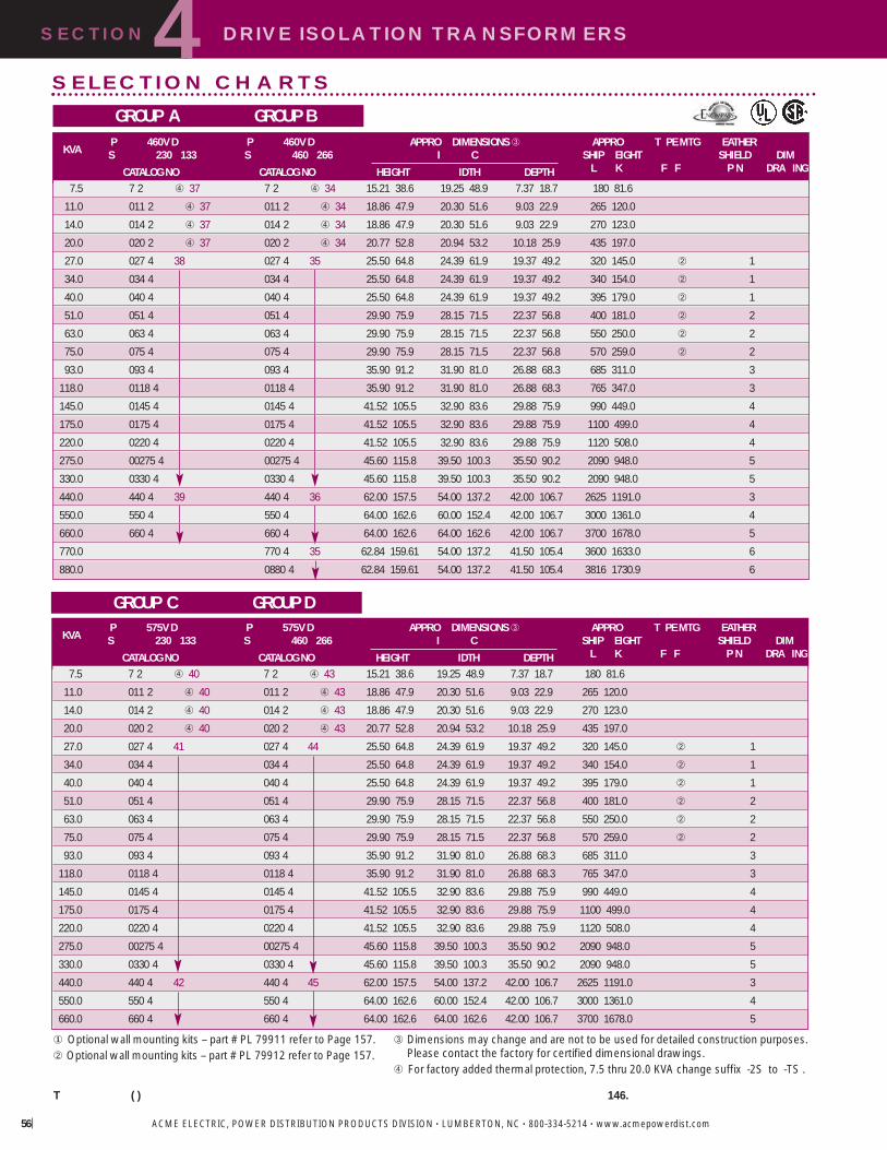
SECTION DRIVE ISOLATION TRANSFORMERS4
ACME ELECTRIC, POWER DISTRIBUTION PRODUCTS DIVISION • LUMBERTON, NC • 800-334-5214 • www.acmepowerdist.com56
� Optional wall mounting kits – part # PL 79911 refer to Page 157.� Optional wall mounting kits – part # PL 79912 refer to Page 157.
T ( ) 146.
SELECTION CHARTS
GROUP A GROUP B
GROUP C GROUP DP 575V D P 575V D APPRO DIMENSIONS� APPRO T PE MTG EATHER
KVA S 230 133 S 460 266 I C SHIP EIGHT SHIELD DIM
CATALOG NO CATALOG NO HEIGHT IDTH DEPTH L K F F P N DRA ING
7.5 7 2 � 40 7 2 � 43 15.21 38.6 19.25 48.9 7.37 18.7 180 81.6
11.0 011 2 � 40 011 2 � 43 18.86 47.9 20.30 51.6 9.03 22.9 265 120.0
14.0 014 2 � 40 014 2 � 43 18.86 47.9 20.30 51.6 9.03 22.9 270 123.0
20.0 020 2 � 40 020 2 � 43 20.77 52.8 20.94 53.2 10.18 25.9 435 197.0
27.0 027 4 41 027 4 44 25.50 64.8 24.39 61.9 19.37 49.2 320 145.0 � 1
34.0 034 4 034 4 25.50 64.8 24.39 61.9 19.37 49.2 340 154.0 � 1
40.0 040 4 040 4 25.50 64.8 24.39 61.9 19.37 49.2 395 179.0 � 1
51.0 051 4 051 4 29.90 75.9 28.15 71.5 22.37 56.8 400 181.0 � 2
63.0 063 4 063 4 29.90 75.9 28.15 71.5 22.37 56.8 550 250.0 � 2
75.0 075 4 075 4 29.90 75.9 28.15 71.5 22.37 56.8 570 259.0 � 2
93.0 093 4 093 4 35.90 91.2 31.90 81.0 26.88 68.3 685 311.0 3
118.0 0118 4 0118 4 35.90 91.2 31.90 81.0 26.88 68.3 765 347.0 3
145.0 0145 4 0145 4 41.52 105.5 32.90 83.6 29.88 75.9 990 449.0 4
175.0 0175 4 0175 4 41.52 105.5 32.90 83.6 29.88 75.9 1100 499.0 4
220.0 0220 4 0220 4 41.52 105.5 32.90 83.6 29.88 75.9 1120 508.0 4
275.0 00275 4 00275 4 45.60 115.8 39.50 100.3 35.50 90.2 2090 948.0 5
330.0 0330 4 0330 4 45.60 115.8 39.50 100.3 35.50 90.2 2090 948.0 5
440.0 440 4 42 440 4 45 62.00 157.5 54.00 137.2 42.00 106.7 2625 1191.0 3
550.0 550 4 550 4 64.00 162.6 60.00 152.4 42.00 106.7 3000 1361.0 4
660.0 660 4 660 4 64.00 162.6 64.00 162.6 42.00 106.7 3700 1678.0 5
� Dimensions may change and are not to be used for detailed construction purposes.Please contact the factory for certified dimensional drawings.
� For factory added thermal protection, 7.5 thru 20.0 KVA change suffix -2S to -TS .
P 460V D P 460V D APPRO DIMENSIONS� APPRO T PE MTG EATHERKVA S 230 133 S 460 266 I C SHIP EIGHT SHIELD DIM
CATALOG NO CATALOG NO HEIGHT IDTH DEPTH L K F F P N DRA ING
7.5 7 2 � 37 7 2 � 34 15.21 38.6 19.25 48.9 7.37 18.7 180 81.6
11.0 011 2 � 37 011 2 � 34 18.86 47.9 20.30 51.6 9.03 22.9 265 120.0
14.0 014 2 � 37 014 2 � 34 18.86 47.9 20.30 51.6 9.03 22.9 270 123.0
20.0 020 2 � 37 020 2 � 34 20.77 52.8 20.94 53.2 10.18 25.9 435 197.0
27.0 027 4 38 027 4 35 25.50 64.8 24.39 61.9 19.37 49.2 320 145.0 � 1
34.0 034 4 034 4 25.50 64.8 24.39 61.9 19.37 49.2 340 154.0 � 1
40.0 040 4 040 4 25.50 64.8 24.39 61.9 19.37 49.2 395 179.0 � 1
51.0 051 4 051 4 29.90 75.9 28.15 71.5 22.37 56.8 400 181.0 � 2
63.0 063 4 063 4 29.90 75.9 28.15 71.5 22.37 56.8 550 250.0 � 2
75.0 075 4 075 4 29.90 75.9 28.15 71.5 22.37 56.8 570 259.0 � 2
93.0 093 4 093 4 35.90 91.2 31.90 81.0 26.88 68.3 685 311.0 3
118.0 0118 4 0118 4 35.90 91.2 31.90 81.0 26.88 68.3 765 347.0 3
145.0 0145 4 0145 4 41.52 105.5 32.90 83.6 29.88 75.9 990 449.0 4
175.0 0175 4 0175 4 41.52 105.5 32.90 83.6 29.88 75.9 1100 499.0 4
220.0 0220 4 0220 4 41.52 105.5 32.90 83.6 29.88 75.9 1120 508.0 4
275.0 00275 4 00275 4 45.60 115.8 39.50 100.3 35.50 90.2 2090 948.0 5
330.0 0330 4 0330 4 45.60 115.8 39.50 100.3 35.50 90.2 2090 948.0 5
440.0 440 4 39 440 4 36 62.00 157.5 54.00 137.2 42.00 106.7 2625 1191.0 3
550.0 550 4 550 4 64.00 162.6 60.00 152.4 42.00 106.7 3000 1361.0 4
660.0 660 4 660 4 64.00 162.6 64.00 162.6 42.00 106.7 3700 1678.0 5
770.0 770 4 35 62.84 159.61 54.00 137.2 41.50 105.4 3600 1633.0 6
880.0 0880 4 62.84 159.61 54.00 137.2 41.50 105.4 3816 1730.9 6

SECTION DRIVE ISOLATION TRANSFORMERS4
ACME ELECTRIC, POWER DISTRIBUTION PRODUCTS DIVISION • LUMBERTON, NC • 800-334-5214 • www.acmepowerdist.com
For Information On The Following, Please Contact The Factory1. Transformers rated primary 230 volts delta, secondary 460Y/266 volts.2. Low temperature rise units using class 220°C insulation with
either 115°C or 80°C rise operating temperature.3. Totally enclosed non-ventilated units.
Windings, Terminations and Construction
� Optional wall mounting kits – part # PL 79911 refer to Page 157.� Optional wall mounting kits – part # PL 79912 refer to Page 157.T ( ) 146.
GROUP E
Figure 1
Figure 2
COIL 1 COIL 2 COIL 3
CORE
BOTTOM OF CASE
COIL 1 COIL 3
THERMAL SWITCH
.625 (1.6 cm) H DIA.EPOXY-RING
CORE
EPOXY LAYER
TERMINAL BLOCK
H
.5H(1.3 cm)
COIL 2
Thermal Switch Kit - PL-79900Acme Thermal Switch Kits are designed for use with single and three phasedrive isolation and distribution transformers. Thermal switch kits are availablefor a one or three sensor system.
Thermal sensors can be field or factory installed in the transformer winding ductsto detect abnormal temperatures. The thermal sensors are a normally closedcontact that opens at 200°C ± 10°C and has a current capacity of 5 amps @120V or 2.5 amps @ 240V. This contact can activate any number of differenttypes of alarms or mechanisms that could warn of a potential failure.
KVA MOUNTING POSITION ILLUSTRATION
27.0 118.0 1145 750 2
PRIMAR SECONDAR INSULATION CONSTRUCTIONKVA INDING INDING S STEM TERMINATION ENCLOSURE CORE
7.5 180 /
11 20 180 /
27 220 220 /
275 660 220 /
PRIMAR 230 D APPRO DIMENSIONS APPRO T PE MTG EATHERKVA SECONDAR 230 133 I C SHIP EIGHT K SHIELD DIM
CATALOG NO H D L K F F I C P N DRA ING
7.5 7 2 62 15.21 38.6 19.25 48.9 7.37 18.7 180 81.6
11.0 011 2 62 18.86 48.0 20.30 51.6 9.03 22.9 265 120.0
14.0 014 2 18.86 48.0 20.30 51.6 9.03 22.9 265 120.0
20.0 020 2 20.77 52.8 20.94 53.2 10.18 25.9 435 197.0
27.0 027 4 59 25.48 64.8 24.39 62.0 19.40 49.3 302 137.0 � 1
34.0 034 4 25.48 64.8 24.39 62.0 19.40 49.3 330 150.0 � 1
40.0 040 4 25.48 64.8 24.39 62.0 19.40 49.3 370 168.0 � 1
51.0 051 4 29.40 74.7 28.15 71.5 22.40 56.9 375 170.0 � 2
63.0 063 4 29.40 74.7 28.15 71.5 22.40 56.9 495 225.0 � 2
75.0 075 4 29.40 74.7 28.15 71.5 22.40 56.9 525 238.0 � 2
93.0 093 4 35.40 89.9 31.90 81.0 26.90 68.3 685 311.0 3
118.0 0118 4 35.40 89.9 31.90 81.0 26.90 68.3 710 322.0 3
145.0 0145 4 41.52 105.5 32.90 83.6 29.90 75.9 980 445.0 4
175.0 0175 4 41.52 105.5 32.90 83.6 29.90 75.9 1110 504.0 4
220.0 0220 4 41.52 105.5 32.90 83.6 29.90 75.9 1120 508.0 4
DRIVE ISOLATION DESIGN FIGURES (Refer to pg 146)

SECTION AC LINE REACTORS4
ACME ELECTRIC, POWER DISTRIBUTION PRODUCTS DIVISION • LUMBERTON, NC • 800-334-5214 • www.acmepowerdist.com58
AC Line Reactors
Protect your sensitive equipment from harmful line disturbanceswith Acme AC Line Reactors. AC Line Reactors help preventequipment failure and downtime, and can add years to thelife of your equipment.
Designed to protect DC motor drives, AC variable frequencydrives and the motors they power. AC Line Reactors allowAcme to augment the Drive Isolation Transformer packageto offer both line and load power quality protection for awide range of applications.
Our product line features flexible design and ease of installationfor use in a variety of applications such as paper machines,process lines, press controls and drive systems, along withtube mills and other sophisticated process equipment. Theseapplications are found in such industries as food and beverage,paper, packaging systems and printing.
FEATURES� Gapped iron core inductor–designed for optimum
performance while providing harmonics compensation.� Precision wound copper coils–maximum protection from
short-circuiting.� Finger-safe terminal blocks (up to 60 HP).� Compact design–allows for more flexible installation.� Amperage ratings of 2 to 600 amps� Available in 3% and 5% impedance� Can be used with 208, 240, 480 and 600 volts.� Covered under Acme s famous 10-year limited warranty.� UR and cUR Recognized.� CE Marked (up to 55 amps)
BENEFITSProtect your motors and motor drives from a variety of powerconditioning problems while realizing the following benefits:
� Protection from damaging voltage drop.� Elimination of nuisance tripping of
drives or circuit breakers.� Reduction of motor current surges and power line spike currents.� Improvement in true power factor of capacitor input drives.� Cooler, quieter operation.� Reduction of harmonic distortion.� Longer life for motors and solid state components.
AC LINE REACTORS DIMENSIONAL DRAWINGS
1-60 HP; 2-80 Amp 75-500 HP; 110-600 Amp

SECTION AC LINE REACTORS4
ACME ELECTRIC, POWER DISTRIBUTION PRODUCTS DIVISION • LUMBERTON, NC • 800-334-5214 • www.acmepowerdist.com 59
Applying Acme AC Line Reactors
Input to Inverter/Drive AC Line Reactors protect your sensitive equipment from noise generated by the drive or inverter. They protect the controller frompower surges, spikes and harmonic distortion.
Output of Inverter/DriveMotors run cooler and quieter with an AC Line Reactor placedbetween the inverter and motor. This application also reduces dv/dt and protects the controller from short circuits and surges.
Multiple Controllers on a Single Power LineEach drive or inverter on a single power line requires its own ACLine Reactor in order to provide adequate surge protection, preventcrosstalk and reduce harmonic distortion.
Multiple Motors Controlled by a Single DriveMultiple motors controlled by a single drive require only one AC LineReactor between the controller and motors.
Acme s three-phase AC Line Reactors can be used as an input filter for adjustable speed DC drives and as input oroutput filters for AC pulse width modulated variable frequency drives. They are bi-directional protective filteringdevices and can be applied in a variety of configurations.
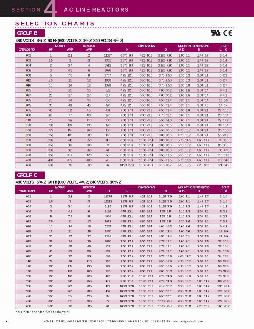
SECTION AC LINE REACTORS4
ACME ELECTRIC, POWER DISTRIBUTION PRODUCTS DIVISION • LUMBERTON, NC • 800-334-5214 • www.acmepowerdist.com6
* Motor HP and Amp rated at 480 volts.
SELECTION CHARTS
GROUP B480 VOLTS, 3% Z, 60 Hz (600 VOLTS, 2.4% Z; 240 VOLTS, 6% Z)
GROUP C480 VOLTS, 5% Z, 60 Hz (600 VOLTS, 4% Z; 240 VOLTS, 10% Z )
MOTOR REACTOR DIMENSIONS MOUNTING DIMENSIONS EIGHTCATALOG NO HP AMP AMP H H D A D B L K
002 1 2.1 2 11027 3.875 9.8 4.25 10.8 3.125 7.90 2.00 5.1 1.44 3.7 3 1.4003 1.5 3 3 7351 3.875 9.8 4.25 10.8 3.125 7.90 2.00 5.1 1.44 3.7 3 1.4004 2 3.4 4 5513 3.875 9.8 4.25 10.8 3.125 7.90 2.00 5.1 1.44 3.7 3 1.4006 3 4.8 6 3676 3.875 9.8 4.25 10.8 3.125 7.90 2.00 5.1 1.44 3.7 3 1.4008 5 7.6 8 2757 4.75 12.1 6.50 16.5 3.75 9.50 2.10 5.3 2.00 5.1 5 2.3012 7.5 11 12 1838 4.75 12.1 6.50 16.5 3.75 9.50 2.10 5.3 2.00 5.1 6 2.7016 10 14 16 1378 4.75 12.1 6.50 16.5 3.75 9.50 2.30 5.8 2.00 5.1 6 2.7025 15 21 25 882 4.75 12.1 6.50 16.5 4.00 10.2 2.60 6.6 2.50 6.4 9 4.1027 20 27 27 817 4.75 12.1 6.50 16.5 4.00 10.2 2.60 6.6 2.50 6.4 9 4.1035 25 34 35 630 4.75 12.1 6.50 16.5 4.50 11.4 3.20 8.1 2.50 6.4 13 5.9045 30 40 45 490 4.75 12.1 6.50 16.5 4.50 11.4 3.20 8.1 3.00 7.6 14 6.4055 40 52 55 401 7.00 17.8 9.00 22.9 4.50 11.4 3.50 8.9 3.60 9.1 22 10.0080 60 77 80 276 7.00 17.8 9.00 22.9 4.75 12.1 3.60 9.1 3.60 9.1 23 10.4110 75 96 110 200 7.00 17.8 9.00 22.9 5.50 14.0 3.60 9.1 3.60 9.1 27 12.2130 100 124 130 170 7.00 17.8 9.00 22.9 6.50 16.5 3.50 8.9 3.60 9.1 34 15.4160 125 156 160 138 7.00 17.8 9.00 22.9 6.50 16.5 4.20 10.7 3.60 9.1 36 16.3200 150 180 200 110 7.00 17.8 9.00 22.9 8.00 20.3 4.20 10.7 3.60 9.1 55 24.9250 200 240 250 88 8.50 21.6 10.80 27.4 8.00 20.3 5.70 14.5 4.60 11.7 74 33.6300 250 302 300 74 8.50 21.6 10.80 27.4 8.00 20.3 5.20 13.2 4.60 11.7 85 38.6360 300 361 360 61 8.50 21.6 10.80 27.4 8.00 20.3 6.20 15.2 4.60 11.7 105 47.6420 350 414 420 53 8.50 21.6 10.80 27.4 8.50 21.6 6.20 15.2 4.60 11.7 113 51.3480 400 477 480 46 8.50 21.6 10.80 27.4 8.50 21.6 6.70 17.0 4.60 11.7 119 54.0600 500 590 600 37 10.93 27.8 16.50 41.9 8.13 20.7 6.50 16.5 7.20 18.3 121 54.9
MOTOR REACTOR DIMENSIONS MOUNTING DIMENSIONS EIGHTCATALOG NO HP AMP AMP H H D A D B L K
002 1 2.1 2 18378 3.875 9.8 4.25 10.8 3.125 7.9 2.00 5.1 1.44 3.7 3 1.4003 1.5 3 3 12252 3.875 9.8 4.25 10.8 3.125 7.9 2.00 5.1 1.44 3.7 3 1.4004 2 3.4 4 9189 3.875 9.8 4.25 10.8 3.125 7.9 2.10 5.3 1.44 3.7 4 1.8006 3 4.8 6 6126 4.75 12.1 6.50 16.5 3.75 9.5 2.10 5.3 2.00 5.1 5 2.3008 5 7.6 8 4594 4.75 12.1 6.50 16.5 3.75 9.5 2.10 5.3 2.00 5.1 6 2.7012 7.5 11 12 3063 4.75 12.1 6.50 16.5 3.75 9.5 2.20 5.6 2.00 5.1 7 3.2016 10 14 16 2297 4.75 12.1 6.50 16.5 4.00 10.2 2.60 6.6 2.00 5.1 9 4.1025 15 21 25 1470 4.75 12.1 6.50 16.5 4.50 11.4 3.00 7.6 2.00 5.1 13 5.9027 20 27 27 1361 4.75 12.1 6.50 16.5 4.50 11.4 2.80 7.1 3.00 7.6 13 5.9035 25 34 35 1050 7.00 17.8 9.00 22.9 4.75 12.1 3.60 9.1 3.00 7.6 23 10.4045 30 40 45 817 7.00 17.8 9.00 22.9 4.75 12.1 3.60 9.1 3.00 7.6 23 10.4055 40 52 55 668 7.00 17.8 9.00 22.9 4.75 12.1 3.60 9.1 3.00 7.6 24 10.9080 60 77 80 459 7.00 17.8 9.00 22.9 5.75 14.6 4.60 11.7 3.60 9.1 34 15.4110 75 96 110 334 7.00 17.8 9.00 22.9 6.50 16.5 4.20 10.7 3.60 9.1 56 25.4130 100 124 130 283 7.00 17.8 9.00 22.9 6.50 16.5 4.20 10.7 3.60 9.1 56 25.4160 125 156 160 230 7.00 17.8 9.00 22.9 8.00 20.3 4.20 10.7 3.60 9.1 70 31.8200 150 180 200 184 8.50 21.6 10.80 27.4 8.25 21.0 5.90 15.0 3.60 9.1 76 34.5250 200 240 250 147 8.50 21.6 10.80 27.4 8.25 21.0 6.20 15.7 4.60 11.7 89 40.4300 250 302 300 123 10.93 27.8 16.50 41.9 8.13 20.7 6.20 15.7 4.60 11.7 106 48.1360 300 361 360 102 10.93 27.8 16.50 41.9 9.50 24.1 8.20 20.8 4.60 11.7 124 56.2420 350 414 420 88 10.93 27.8 16.50 41.9 9.50 24.1 8.20 20.8 4.60 11.7 124 56.2480 400 477 480 77 10.93 27.8 16.50 41.9 10.13 25.7 8.20 20.8 4.60 11.7 129 58.5600 500 590 600 61 10.93 27.8 16.50 41.9 10.13 25.7 8.20 20.8 7.20 18.3 190 86.2
®

SECTION ENCAPSULATED AC LINE REACTORS4
ACME ELECTRIC, POWER DISTRIBUTION PRODUCTS DIVISION • LUMBERTON, NC • 800-334-5214 • www.acmepowerdist.com 6
Acme s Encapsulated AC Line Reactors are designed toprotect DC motor drives and AC variable frequency drives ormotors–– with one important difference. These line reactorsare completely enclosed, so the unit can be mounted outsidethe control panel.
Ideal for applications such as process lines, paper machines,casters, tube mills, tire assembly, laminators, press controlsand drive systems. Acme s Encapsulated AC Line Reactorsimmerse the core and coil assembly in an electrical grade silicaand resin compound that seals out moisture and potentialcorrosives. These Line Reactors are housed in a NEMA 3REnclosure suitable for indoor or outdoor applications. What smore, these encapsulated line reactors are extremely conve-nient to install. They can be floor or wall mounted and frontaccess makes wiring easy.
H
DWDW
H H
W D
* All units are available with stainless steel enclosures–consult factory.** Motor HP and Amp rated at 480 volts.
Encapsulated AC Line ReactorsFEATURES� UL Type 3R enclosure.� Available with stainless steel enclosure.� Versatile mounting options to meet special application
requirements.� Large wiring compartment remains cool.� No conduit or pull boxes needed.� Front access to compartment simplifies wiring.� Flexible copper leadwire terminates outside wiring
compartment for quick connections.� Dual-size knockouts in both sides and bottom of compartment
for added flexibility in wiring.� Ground studs for use with non-metallic conduit.� UL and cUL Listed, CE Marked.� Backed by Acme s 10-year limited warranty.
BENEFITS� Completely enclosed design provides protection against
corrosion and insulation deterioration in washdown and harsh environment.
� Easy to install and wire.� Protects against a whole range of power conditioning problems.� Eliminates motor failure due to poor power quality.� Reduces downtime.� Extends the life of your equipment.
ENCAPSULATED AC LINE REACTORS DIMENSIONAL DRAWINGS

SELECTION CHARTS
GROUP BENCAPSULATED AC LINE REACTORS*480 VOLTS, 3% Z, 60 Hz (600 VOLTS, 2.4% Z; 240 VOLTS, 6% Z )
GROUP CENCAPSULATED AC LINE REACTORS*480 VOLTS, 5% Z, 60 Hz (600 VOLTS, 4% Z; 240 VOLTS, 10% Z )
MOTOR REACTOR DIMENSIONS DIMENSIONAL EIGHTCATALOG NO HP AMP AMP H H D DRA INGS
002 1 2.1 2 11027 9.68 24.6 4.75 24.6 4.5 11.4 10 4.5
003 1.5 3 3 7351 9.68 24.6 4.75 24.6 4.5 11.4 10 4.5
004 2 3.4 4 5513 9.68 24.6 4.75 24.6 4.5 11.4 10 4.5
006 3 4.8 6 3676 9.68 24.6 4.75 24.6 4.5 11.4 10 4.5
008 5 7.6 8 2757 11.5 29.2 10.31 26.2 7.13 18.1 24 10.9
012 7.5 11 12 1838 11.5 29.2 10.31 26.2 7.13 18.1 24 10.9
016 10 14 16 1378 11.5 29.2 10.31 26.2 7.13 18.1 25 11.3
025 15 21 25 882 11.5 29.2 10.31 26.2 7.13 18.1 28 12.7
027 20 27 27 817 11.5 29.2 10.31 26.2 7.13 18.1 28 12.7
035 25 34 35 630 11.5 29.2 10.31 26.2 7.13 18.1 32 14.5
045 30 40 45 490 11.5 29.2 10.31 26.2 7.13 18.1 33 15.0
055 40 52 55 401 11.83 30.0 14.17 36.0 8.82 22.4 73 33.1
080 60 77 80 276 11.83 30.0 14.17 36.0 8.82 22.4 75 34.0
110 75 96 110 200 11.83 30.0 14.17 36.0 8.82 22.4 78 35.4
130 100 124 130 170 11.83 30.0 14.17 36.0 8.82 22.4 85 38.6
160 125 156 160 138 11.83 30.0 14.17 36.0 8.82 22.4 87 39.5
MOTOR REACTOR DIMENSIONS DIMENSIONAL EIGHTCATALOG NO HP AMP AMP H H D DRA INGS
002 1 2 2 18378 9.68 24.6 4.75 24.6 4.5 11.4 10 4.5
003 1.5 3 3 12252 9.68 24.6 4.75 24.6 4.5 11.4 10 4.5
004 2 4 4 9189 9.68 24.6 4.75 24.6 4.5 11.4 10 4.5
006 3 6 6 6126 11.5 29.2 10.31 26.2 7.13 18.1 24 10.9
008 5 8 8 4594 11.5 29.2 10.31 26.2 7.13 18.1 24 10.9
012 7.5 12 12 3063 11.5 29.2 10.31 26.2 7.13 18.1 26 11.8
016 10 16 16 2297 11.5 29.2 10.31 26.2 7.13 18.1 28 12.7
025 15 25 25 1470 11.5 29.2 10.31 26.2 7.13 18.1 32 14.5
027 20 27 27 1361 11.5 29.2 10.31 26.2 7.13 18.1 32 14.5
035 25 35 35 1050 11.83 30.0 14.17 36.0 8.82 22.4 74 33.6
045 30 45 45 817 11.83 30.0 14.17 36.0 8.82 22.4 75 34.0
055 40 55 55 668 11.83 30.0 14.17 36.0 8.82 22.4 75 34.0
080 60 80 80 459 11.83 30.0 14.17 36.0 8.82 22.4 85 38.6
110 75 110 110 334 11.83 30.0 14.17 36.0 8.82 22.4 107 48.5
130 100 130 130 263 11.83 30.0 14.17 36.0 8.82 22.4 107 48.5
160 125 160 160 230 11.83 30.0 14.17 36.0 8.82 22.4 121 54.9
ENCAPSULATED AC LINE REACTORSSECTION4
ACME ELECTRIC, POWER DISTRIBUTION PRODUCTS DIVISION • LUMBERTON, NC • 800-334-5214 • www.acmepowerdist.com62
C

SECTION
Selection Steps . . . . . . . . . . . . . . . . . . . . . . . . . . .64
TA S O C & C . . . . . . . . . . . . . .65-67Selection Charts . . . . . . . . . . . . . . . . . . . . . . . .72-76Primary & Secondary Fuse Information . . . . . .66-67Wiring Diagrams & Dimensions . . . . . . . . . . . . . . .77
TB S O C & C . . . . . . . . . . . . . .68-70Selection Charts . . . . . . . . . . . . . . . . . . . . . . . .71-76Primary & Secondary Fuse Information . . . . . .69-70Wiring Diagrams & Dimensions . . . . . . . . . . . . . . .78
H E C T . . . .79
AE/CE S E T . . . .80-86Selection Charts . . . . . . . . . . . . . . . . . . . . . . . .82-86
FINGER/G ARDIndustrial Control Transformer . . . . . . . . . . . . .88-92Selection Charts . . . . . . . . . . . . . . . . . . . . . . . . . . .89
IND STRIALCONTROL
TRANSFORMERS
5
NEW
NEW

5SECTION INDUSTRIAL CONTROL TRANSFORMERS
ACME ELECTRIC, POWER DISTRIBUTION PRODUCTS DIVISION • LUMBERTON, NC • 800-334-5214 • www.acmepowerdist.com64
To make the proper transformer selection,the load must be completely analyzed. . .which involves every electrically energizedcomponent in the control circuit.
All electromagnetic control devices havetwo current requirements; the first toenergize the coil; the second to maintainthe contact for a definite period of time.The initial energizing of the coil, whichtakes 5 to 20 milliseconds, requires manytimes more current than normal. This isreferred to as - . . .which is immediately followed by thesealed volt-amperes the amount ofcurrent required to hold the contact inthe circuit.
Easy, five step selection1. Determine the voltage and frequency of
supply circuit: Example: 460 Volts, 60 Hz.
2. Determine the total inrush VA of thecontrol circuits from the manufacturer sdata or the contactor data table. Do notneglect the current requirements of indicating lights and timing devices that do not have an inrush VA but are energized at the same time as the other components in the circuit. Their total VA should be added to the total inrush VA.
3. Refer to the regulation data chart. If the supply circuit voltage (Step 1) is reasonably stable and fluctuates no more than ± 5%, refer to the 90% Secondary Voltage column. If it fluctuates as much as ± 10%, referto the 95% Secondary Voltage column.Go down the column you have selecteduntil you arrive at the inrush VA closest to, but not less than, the inrush VA of your control circuit.
4. Read to the far left side of the chart and you have selected the continuousnominal VA rating of the transformer needed. The secondary voltage that will be delivered under inrush conditionswill be either 85%, 90%, or 95% of therated secondary voltage depending onthe column selected from the regulation data chart. The total sealed VA of the control circuit must not exceed the nominal VA rating of the transformer selected from the manufacturer s data or the contactor s data table.
5. Refer to the specification tables on the following pages to select a transformer according to the required continuous nominal VA and primary/secondary voltages.
��Data is most current at time of printing. Contact individual manufacturer for updates.
TABLE 2. Typical Magnetic Motor Starter & Contactor Data �60 Hz, 120 Volt, 3-Pole
Selecting Industrial Control Transformers
N E M A S
C 00 0 1 2 3 4 5
A L
500192 192 240 660 1225 2040 1490
29 29 29 45 69 110 96
53 110 175 240 580 1000 1950
15 20 22 31 43 65 98
85 85 100 150 490 900 1200
9 9 11.5 15 35 55 65
218 218 218 218 310 957 1518
25 25 25 25 26 75 116
151 151 151 528 1152 1248 2580
24 24 24 60 83 86 191
210 210 210 210 724 880 1790
18 18 18 18 30 39 295
76 76 76 194 365 530 1630
12 12 12 21 35 40 110
165 245 245 311 700 1185 2970
33 27 27 37 46 85 212
160 160 160 160 625 625 1700
25 25 25 25 50 50 180
187 103 103 1158
15 20 20 100
102 103 103 140 390 1158 11581
13 20 20 24 50 100 100
I VA @ 20 40 P FN 85 S V 90 S V 95 S VVA R
20 P F 40 P F 20 P F 40 P F 20 P F 40 P F50 362 224 289 179 217 13475 579 354 462 283 345 211
100 839 522 664 413 489 304150 1326 842 1003 637 679 431250 3447 2281 2462 1629 1477 977300 3894 2618 2812 1890 1731 1163350 5418 3689 3870 2635 2322 1581500 6496 4575 4691 3304 2887 2033750 8377 5811 5913 4102 3449 2393
1000 11329 9005 7789 6191 4248 33771500 25519 18803 18013 13273 10508 77422000 28178 21600 19372 14850 10566 81003000 34797 28391 24562 20041 14328 116905000 138500 84542 100000 61058 61550 37574
TABLE 1. Inrush VA

5SECTION TA SERIES OPEN CORE & COIL INDUSTRIAL CONTROL TRANSFORMERS
ACME ELECTRIC, POWER DISTRIBUTION PRODUCTS DIVISION • LUMBERTON, NC • 800-334-5214 • www.acmepowerdist.com 65
TA Series Open Core & Coil Industrial Control Transformers
Industrial control transformers are used to reducesupply voltages to 230 V or lower for the operationof electromagnetic devices such as contactors,solenoids, relays, and timers. They are especiallydesigned to accommodate the momentary currentinrush caused when electromagnetic componentsare energized . . . without sacrificing secondaryvoltage stability beyond practical limits.
Acme Industrial Control Transformers are dry-type,step-down transformers with the secondarycontrol circuit isolated from the primary line circuitto assure maximum safety.
Voltage regulation of Acme Industrial ControlTransformers exceeds standards recommended bythe National Electrical Manufacturers Association.Secondary circuit voltage drop between no-loadand momentary overload remains exceptionally low.This excellent secondary circuit voltage regulationassures reliable operation of electromagneticcomponents and may permit the use of a smallerand less expensive industrial control transformer.
FEATURES� Constructed with high quality silicon steel
lamination to minimize core losses and increase efficiency.
� Designs incorporate precision wound coils forimproved regulation.
� Primary fuse blocks and secondary fuse kitsavailable and easily adaptable.
� Series-parallel connecting links save wiring and labor costs.
� Sturdy phenolic terminal panel protects the coil from foreign objects and mechanical damage.
� Copper windings on all groups.� 130°C Insulation class. 80°C temperature rise.� Wire retention on both primary and secondary
terminals.� Mounting plate adapts to various mounting
dimensions.� Voltage regulation exceeds NEMA requirements.� UL Listed, CSA Certified.� Attractive finish, nameplate, and design features
enhance the end product.
Integrally Mounted Fuse Blocks
Primary Fuse Kit with Snap-onSecondary Fuse Block
Jumper Link Connections
Secondary Fuse Clips
Acme Industrial Control TransformersMeet or Exceed UL,CSA,NEMA & ANSIAcme Industrial Control Transformers 50 through 5000 VA are ULListed, File E79947 and CSA certified, File 7357.
Laminations High-permeability silicon steel continuouslyannealed to minimize core losses.
Magnet Wire Copper magnet wire is coated with hightemperature-resisting insulating film.
Coils Precision wound by machine; total turns per coil automatically counted.
Mounting Heavy steel mounting plates add strength to coreconstruction and provide firm mounting, slotted to facilitate installation.
Terminal Boards Sturdy phenolic terminal boards.
Sizing Primary Fuses:Primary Amps < 2, fuse size is 300% of rated primary current.Primary Amps 2< 9, fuse size is 167% of rated primary current.Primary Amps > 9, fuse size is 125% of rated primary current.
Sizing Secondary Fuses:Secondary Amps < 9, fuse size is 167% of rated secondary current.Secondary Amps > 9, fuse size is 125% of rated secondary current.

SECTION TA SERIES OPEN CORE & COIL INDUSTRIAL CONTROL TRANSFORMERS5
ACME ELECTRIC, POWER DISTRIBUTION PRODUCTS DIVISION • LUMBERTON, NC • 800-334-5214 • www.acmepowerdist.com66
� Meets NEC Article 450 and UL-508 requirements.� For use with class CC fuses.� Eliminates remote mounting of primary overcurrent protection.� Covered by Acme Electric 10-year limited warranty.Field installation is fast and easy. Simply loosen the mountinghardware (Fig. 1), slide the bracket over the transformer and re-tighten the mounting hardware. Make the proper connectionswith the factory furnished jumpers (Fig. 2) and your unit is readyfor operation.
1. To mount the primary fuse kit bracket, remove the two 1/4" (.64 cm) sheet metal screws on the terminal panel on the primary (H side) of the transformer.
2. Place the slots in the fuse kit mounting bracket over the holes in the terminal and mounting bracket. To secure the fuse kit, reinsert the two 1/4" (.64 cm) sheet metal screws and tighten securely.
3. Tighten all mounting screws securely–this will secure the mounting bracket.
4. Attach the female quick connect of the jumpers supplied with the fuse kit to male quick connects on the right side of the fuse blocks – one jumper to each of the blocks.
5. Connect the ring terminal of the jumpers to the appropriate screw terminals of the transformers primary (H side). Refer to the transformer name plate for proper terminal connections.
6. Connect primary supply line leads to the screw terminals on the left side of the block –one line lead to each of the fuse blocks.
TA Series Primary Fuse Kits
Instructions for TA Series Primary Fuse KitType PL-112706 & PL-112707: Using 2 Class CC Dual Element Fuses (3000-5000 VA)
Type PL-112700 Through PL-112705: Using 2Class CC Dual Element Fuses (not supplied)
PRIMARY (H SIDE)
SECONDARY (X SIDE)
PRIMARY (H SIDE)
INPUTSUPPLY
LINE
PRIMARY (H SIDE)
SECONDARY (X SIDE) PRIMARY (H SIDE)
SECONDARY (X SIDE)
INPUTSUPPLY
LINE
F 1
F 2
Primary Fuse Sizing Chart�
� Fuse size based on time delay class CC fuses.NOTE: Bold lines indicate changes in the percent of rated current used to calculate fuse sizes in accordance with article 450 of the NEC.
VA 120 V 208 V 230 V 240 V 277 V 380 V 416 V 440 V 460 V 480 V 550 V 600 V50 1.2 0.6 0.6 0.6 0.6 0.3 0.3 0.3 0.3 0.3 0.3 0.375 1.9 1.0 1.0 1.0 0.8 0.6 0.6 0.6 0.5 0.5 0.4 0.4100 2.5 1.5 1.3 1.3 1.0 0.8 0.8 0.6 0.6 0.6 0.6 0.5150 3.8 2.0 2.0 1.9 1.5 1.2 1.2 1.0 1.0 1.0 0.8 0.8250 3.5 3.5 3.5 3.0 3.0 2.0 1.8 1.8 1.5 1.5 1.4 1.2300 4.0 4.0 4.0 3.5 3.0 2.5 2.5 2.0 2.0 1.9 1.5 1.5350 5.0 5.0 4.5 4.0 4.0 2.5 2.5 2.5 2.0 2.0 1.9 1.8500 7.0 4.0 3.5 3.5 5.5 4.0 3.5 3.5 3.5 3.0 3.0 2.5750 10.0 6.0 5.5 5.0 4.5 6.0 5.5 5.0 5.0 5.0 4.0 4.01000 15.0 8.0 7.0 7.0 6.0 4.5 4.0 3.5 3.5 3.5 5.5 5.01500 20.0 12.0 12.0 12.0 10.0 7.0 6.0 6.0 5.5 5.5 5.0 4.52000 25.0 12.0 15.0 15.0 12.0 9.0 8.0 8.0 7.5 7.0 6.0 6.03000 30.0 20.0 20.0 20.0 15.0 15.0 12.0 12.0 12.0 12.0 10.0 9.05000 30.0 30.0 30.0 25.0 20.0 15.0 15.0 15.0 15.0 12.0 15.0

SECTION TA SERIES OPEN CORE & COIL INDUSTRIAL CONTROL TRANSFORMERS5
ACME ELECTRIC, POWER DISTRIBUTION PRODUCTS DIVISION • LUMBERTON, NC • 800-334-5214 • www.acmepowerdist.com 6
� Mount secondary fuse clips on terminalsX1 and F or F1 using the screws suppliedwith the transformer.
� Connect secondary load lines to terminalsX2 and F or F2.
� Use dual -element slow-blowing fusessuch as Bussmann MFG., Fusetron TypeFNM, Littelfuse or Shawmut (not suppliedwith fuse kits).
PL-112600/601 Fuse Kit PL-112602 Fuse Kit
1. To attach secondary fuse kit PL-112603 to primary fuse kits PL-112700 thru PL-112707 snap the secondary single pole fuse block onto the unlabeled side of the primary double pole fuse block. (See Figure 1)
2. Install the fuse kits as instructed under the primary fuse kit instructions on page 75.
3. Select the appropriate pair of jumpers for making the connections between the secondary fuse block and the secondary (X-side) of the transformer.
4. Connect the female quick-connect of the jumpers supplied to one of the male quick-connects of the secondary fuse block - one jumper to each end of the fuse block. (See Figure 2)
5. Connect the ring terminal of the jumpers suppliedto screw terminals X1 and F or F1 on the secondary(X-side) of the transformer.
6. Connect secondary load lines to terminals X2 and F or F2.
SECONDARY (X SIDE)
F 1
F 2
Jumper Link ConnectionsGroup A Series: 240 V parallel: 120 VGroup B Series: 480 V parallel: 240 VGroup F series: 230 V parallel: 115 VGroup I Series: 24 V parallel: 12 VGroup J Series: 480 V & 240 V: 240 V & 120 VGroup K Series: 240 V: 120 V
TA Series Instructions for Secondary Fuse KitType PL-112603: use dual element slow-blow fuse 13/32" x 1-1/2" (1.0 x 3.8 cm)
SeriesConnection
ParallelConnection
E : 150 VA transformer TA-2-32404 does not havequick connect terminals.
TA Series Secondary Fuse KitsType PL-112600, 601, 602: Use Dual Element Slow-Blow Fuse

TB SERIES OPEN CORE & COIL INDUSTRIAL CONTROL TRANSFORMERSSECTION
ACME ELECTRIC, POWER DISTRIBUTION PRODUCTS DIVISION • LUMBERTON, NC • 800-334-5214 • www.acmepowerdist.com6
Acme s TB Series Industrial Control Transformers are especiallydesigned to accommodate the momentary current inrush causedwhen electromagnetic components are energized. . . withoutsacrificing secondary voltage stability beyond practical limits.
Acme s TB Series transformers are dry-type, step-down trans-formers with the secondary control circuit isolated from theprimary line circuit to assure maximum safety.
Voltage regulation of Acme s TB Series transformers exceedsstandards recommended by the National Electrical ManufacturersAssociation. Secondary circuit voltage drop between no-load andmomentary overload remains exceptionally low. This excellentsecondary circuit voltage regulation assures reliable operation ofelectromagnetic components and may permit the use of a smallerand less expensive industrial control transformer.
FEATURES & BENEFITS� 600 volt class and below.� 50–1000 VA, 50/60 Hz.� 80°C temperature rise, 130°C insulation class.� Constructed with high quality silicon steel lamination to
minimize core losses and increase efficiency.� Designs incorporate precision split bobbin wound coils for
improved regulation.� Primary fuse blocks and secondary fuse kits available and
easily adaptable.� Series-parallel connecting links save wiring and labor costs.� Terminal blocks allow full access for ring terminals for easy
installation even with solid strand conductors.� Integrally molded terminal blocks with isolation barriers to
prevent arc over.� Footprint matches TA Series for easy interchangeability.� Copper windings on all groups.� Heavy gauge steel mounting plate adapts to various
mounting dimensions.� Voltage regulation exceeds NEMA requirements.� UL Listed and CSA Certified.� Meets or exceeds UL, CSA, NEMA, ANSI and
OSHA Standards.� Ten-year limited warranty.
APPLICATIONS� Motor Starters� Contactors� Solenoids� Timer Circuits� Relays� Control Panels� Robotics
TB Series Open Core & Coil Industrial Control Transformers
NEW
5

TB SERIES OPEN CORE & COIL INDUSTRIAL CONTROL TRANSFORMERS5SECTION
ACME ELECTRIC, POWER DISTRIBUTION PRODUCTS DIVISION • LUMBERTON, NC • 800-334-5214 • www.acmepowerdist.com 6
TB Series Primary Fuse KitsType PL-112700 Through PL-112705: Using 2Class CC Dual Element Fuses (not supplied)
F 1
NEW
Primary Fuse Sizing Chart�
� Fuse size based on time delay class CC fuses.NOTE: Bold lines indicate changes in the percent of rated current used to calculate fuse sizes in accordance with article 450 of the NEC.
VA 120 V 208 V 230 V 240 V 277 V 380 V 416 V 440 V 460 V 480 V 550 V 600 V50 1.2 0.6 0.6 0.6 0.6 0.3 0.3 0.3 0.3 0.3 0.3 0.375 1.9 1.0 1.0 1.0 0.8 0.6 0.6 0.6 0.5 0.5 0.4 0.4100 2.5 1.5 1.3 1.3 1.0 0.8 0.8 0.6 0.6 0.6 0.6 0.5150 3.8 2.0 2.0 1.9 1.5 1.2 1.2 1.0 1.0 1.0 0.8 0.8250 3.5 3.5 3.5 3.0 3.0 2.0 1.8 1.8 1.5 1.5 1.4 1.2300 4.0 4.0 4.0 3.5 3.0 2.5 2.5 2.0 2.0 1.9 1.5 1.5350 5.0 5.0 4.5 4.0 4.0 2.5 2.5 2.5 2.0 2.0 1.9 1.8500 7.0 4.0 3.5 3.5 5.5 4.0 3.5 3.5 3.5 3.0 3.0 2.5750 10.0 6.0 5.5 5.0 4.5 6.0 5.5 5.0 5.0 5.0 4.0 4.01000 15.0 8.0 7.0 7.0 6.0 4.5 4.0 3.5 3.5 3.5 5.5 5.01500 20.0 12.0 12.0 12.0 10.0 7.0 6.0 6.0 5.5 5.5 5.0 4.52000 25.0 12.0 15.0 15.0 12.0 9.0 8.0 8.0 7.5 7.0 6.0 6.03000 30.0 20.0 20.0 20.0 15.0 15.0 12.0 12.0 12.0 12.0 10.0 9.05000 30.0 30.0 30.0 25.0 20.0 15.0 15.0 15.0 15.0 12.0 15.0
F 2
� Meets NEC Article 450 and UL-508 requirements.� For use with class CC fuses.� Eliminates remote mounting of primary
overcurrent protection.� Covered by Acme Electric 10-year
limited warranty.
Field installation is fast and easy. Simply loosenthe mounting hardware (Fig. 1), slide the bracketover the transformer and re-tighten the mountinghardware. Make the proper connections with thefactory furnished jumpers (Fig. 2) and your unit isready for operation.

SECTION5TB SERIES OPEN CORE & COIL INDUSTRIAL CONTROL TRANSFORMERS
ACME ELECTRIC, POWER DISTRIBUTION PRODUCTS DIVISION • LUMBERTON, NC • 800-334-5214 • www.acmepowerdist.com70
Catalog Number VA T pe
PL-79924* 50-1000 1/4 x 1-1/4PL-79930 50-350 13/32 x 1-1/2PL-79931 500-1000 13/32 x 1-1/2
� Mount secondary fuse clips on terminals X1 and F or F1using the screws supplied with the transformer.
� Connect secondary load lines to terminals X2 and F or F2.Use Jumper Link to connect F1 and F2.
� Use dual -element slow-blowing fuses such as BussmannMFG., Fusetron Type FNM, Littelfuse or Ferraz Shawmut(not supplied with fuse kits).
* PL-79924: Use fuse kit on all transformers except 750 & 1000 VAwith 24 volt secondary.
SecondarFuse Kit
1. To attach secondary fuse kit PL -112603 toprimary fuse kits PL-112700 thru PL-112705snap the secondary single pole fuse block onto the unlabeled side of the primary doublepole fuse block. (See Figure 1)
2. Install the fuse kits as instructed under theprimary fuse kit instructions on page 70.
3. Select the appropriate pair of jumpers for making the connections between the secondary fuse block and the secondary(X-side) of the transformer.
4. Connect the female quick-connect of the jumpers supplied to one of the male quick-connects of the secondary fuse block - one jumper to each end of the fuse block. (See Figure 2)
5. Connect the ring terminal of the jumpers supplied to screw terminals X1 and F or F1on the secondary (X-side) of the transformer.
6. Connect secondary load lines to terminals X2 and F or F2.
F 1
F 2
Instructions for TB Series Secondary Fuse KitType PL-112603: use dual element slow-blow fuse 13/32" x 1-1/2" (1.0 x 3.8 cm)
TB Series Secondary Fuse KitsType PL-79924, PL-79930, & PL-79931: Use Dual Element Slow-Blow Fuse
NEW
NEW

TA & TB SERIES OPEN CORE & COIL INDUSTRIAL CONTROL TRANSFORMERS5SECTION
ACME ELECTRIC, POWER DISTRIBUTION PRODUCTS DIVISION • LUMBERTON, NC • 800-334-5214 • www.acmepowerdist.com 71
� Secondary Fuse Kit PL-112603 may be substituted for PL-112600 thru PL-112602 when Primary Fuse Kit is used. See page 71.� See chart for integrally mounted fuse block catalog number suffix.
120 X 240 PRIMARY VOLTS 24 SECONDARY VOLTS 1 , 50/60 Hz
GROUP A
SELECTION CHARTSNEW
.
240 X 480, 230 X 460, 220 X 440 PRIMARY VOLTS 120/115/110 SECONDARY VOLTS 1 , 50/60 Hz
GROUP B
CATALOG VA OUTPUT APPRO DIMENSIONS APPRO PRIMAR SECONDAR SECONDARNO � RATING AMPS INCHES CM SHIP EIGHT FUSE BLOCK FUSE KIT� FUSE SI E
@ 120V A B C D E F LBS KG PART NO PART NO 120 VOLTS
81210 � 50 0.42 4.23 3.00 2.70 2.50 2.13 .22 .50 4 112700 6/1010.7 7.6 6.8 6.4 5.4 0.6 1.3 1.8
81201 � 75 0.63 4.74 3.00 2.70 2.50 2.61 .22 .50 4 112700 112.0 7.6 6.8 6.4 6.6 0.6 1.3 1.8
81211 � 100 0.83 4.90 3.00 2.70 2.50 2.81 .22 .50 4 112700 11/412.4 7.6 6.8 6.4 7.1 0.6 1.3 1.8
81212 � 150 1.25 5.00 3.75 3.40 3.13 2.81 .22 .50 6 112701 212.7 9.5 8.6 8.0 7.1 0.6 1.3 2.7
81213 � 250 2.08 5.57 4.50 3.84 3.75 3.13 .22 .50 9 112702 32/1014.1 11.4 9.8 9.5 8.0 0.6 1.3 4.1
81200 � 300 2.50 5.57 4.50 3.84 3.75 3.13 .22 .50 10 112702 414.1 11.4 9.8 9.5 8.0 0.6 1.3 4.5
81214 � 350 2.92 6.32 4.50 3.84 3.75 3.83 .22 .50 12 112702 41/216.1 11.4 9.8 9.5 9.7 0.6 1.3 5.4
81215 � 500 4.17 6.30 5.25 4.47 4.06 3.81 .22 .50 15 112704 61/416.0 13.3 11.4 10.3 9.7 0.6 1.3 6.8
81216 � 750 6.25 6.65 5.25 4.47 4.38 5.13 .31 .50 23 112704 1016.9 13.3 11.4 11.1 13.0 0.8 1.3 10.4
81217 � 1000 8.33 7.58 6.75 5.78 5.75 3.69 .31 .50 25 112705 112601 1219.3 17.1 14.7 14.6 9.4 0.8 1.3 11.3
NEW
CATALOG VA OUTPUT APPRO DIMENSIONS APPRO PRIMAR SECONDAR SECONDARNO � RATING AMPS I C SHIP EIGHT FUSE BLOCK FUSE KIT� FUSE SI E
A B C D E F L K PART NO PART NO 24 VOLTS
81141 � 50 2.08 4.23 3.00 2.70 2.50 2.13 .22 .50 4 112700 3 2/10
10.7 7.6 6.8 6.4 5.4 0.6 1.3 1.8
81142 � 75 3.13 4.74 3.00 2.70 2.50 2.61 .22 .50 4 112700 512.0 7.6 6.8 6.4 6.6 0.6 1.3 1.8
81143 � 100 4.17 4.90 3.00 2.70 2.50 2.81 .22 .50 4 112700 61/4
12.4 7.6 6.8 6.4 7.1 0.6 1.3 1.8
81144 � 150 6.25 4.78 3.75 3.40 3.13 2.63 .22 .50 6 112701 1012.1 9.5 8.6 8.0 6.7 0.6 1.3 2.7
81146 � 250 10.42 5.08 4.50 3.84 3.75 3.05 .22 .50 9 112702 1512.9 11.4 9.8 9.5 7.7 0.6 1.3 4.1
81148 � 350 14.58 6.12 4.50 3.84 3.75 4.06 .22 .50 13 112702 2015.5 11.4 9.8 9.5 10.3 0.6 1.3 5.9
81149 � 500 20.83 5.90 5.25 4.47 4.38 4.19 .31 .50 16 112704 3015.0 13.3 11.4 11.1 10.6 0.8 1.3 7.3
81150 750 31.25 7.53 5.25 4.47 4.38 5.25 .31 .50 24 11270419.1 13.3 11.4 11.1 13.3 0.8 1.3 10.9
81151 1000 41.67 7.43 6.75 5.72 5.75 3.81 .31 .50 26 11270518.9 17.1 14.5 14.6 9.7 0.8 1.3 11.8

SECTION TA & TB SERIES OPEN CORE & COIL INDUSTRIAL CONTROL TRANSFORMERS5
ACME ELECTRIC, POWER DISTRIBUTION PRODUCTS DIVISION • LUMBERTON, NC • 800-334-5214 • www.acmepowerdist.com
ADD SUFFIXTO CATALOG NO. CONFIGURATION
2 23 3
1004 2
50 75
.
� Secondary Fuse Kit PL-112603 may be substituted for PL-112600 thru PL-112602 when Primary Fuse Kit is used. See page 71.� See chart for integrally mounted fuse block catalog number suffix.
240 X 480, 230 X 460, 220 X 440 PRIMARY VOLTS — 120/115/110 SECONDARY VOLTS — 1Ø, 50/60 HzGROUP B
Integrally Mounted Fuse Blocks Available:
Consult factory for other sizes available.
NEW
.
(CONTINUED)
240/480/600, 230/460/575, 220/440/550 PRIMARY VOLTS 120/100, 115/95, 110/90 SECONDARY VOLTS 1 , 50/60 Hz
GROUP C
CATALOG VA OUTPUT APPRO DIMENSIONS APPRO PRIMAR SECONDAR SECONDARNO � RATING AMPS INCHES CM SHIP EIGHT FUSE BLOCK FUSE KIT� FUSE SI E
@ 120V A B C D E F LBS KG PART NO PART NO 120 VOLTS
2 81218 1500 12.50 8.80 6.75 5.72 5.75 5.75 .31 .50 43 112705 112601 1522.4 17.1 14.5 14.6 14.6 0.8 1.3 19.5
2 81219 2000 16.67 9.25 6.75 5.72 5.75 6.38 .31 .50 49 112705 112601 2023.5 17.1 14.5 14.6 16.2 0.8 1.3 22.2
2 81220 3000 25.00 8.81 7.50 8.34 6.50 7.52 .41 .81 70 11270622.4 19.1 21.2 16.5 19.1 1.0 2.1 31.8
2 81221 5000 41.67 7.52 11.92 9.49 6.75 6.25 .41 .81 125 11270719.1 30.3 24.1 17.1 15.9 1.0 2.1 56.7
CATALOG VA OUTPUT APPRO DIMENSIONS APPRO PRIMAR SECONDAR SECONDARNO RATING AMPS INCHES CM SHIP EIGHT FUSE BLOCK FUSE KIT� FUSE SI E
@ 120V A B C D E F LBS KG PART NO PART NO 120 VOLTS
81000 50 0.42 4.56 3.00 2.70 2.50 2.61 .22 .50 4 112700 6/1011.6 7.6 6.8 6.4 6.6 0.6 1.3 1.8
81009 75 0.63 4.90 3.00 2.70 2.50 2.81 .22 .50 4 112700 112.4 7.6 6.8 6.4 7.1 0.6 1.3 1.8
81001 100 0.83 5.36 3.00 2.70 2.50 3.26 .22 .50 5 112700 11/413.6 7.6 6.8 6.4 8.3 0.6 1.3 2.3
81002 150 1.25 5.00 3.75 3.40 3.13 3.06 .22 .50 7 112701 212.7 9.5 8.6 8.0 7.8 0.6 1.3 3.2
81003 250 2.08 5.57 4.50 3.84 3.75 3.50 .22 .50 11 112702 32/1014.1 11.4 9.8 9.5 8.9 0.6 1.3 5.0
81020 300 2.50 6.48 4.65 4.15 4.06 4.06 .22 .50 15 112702 416.5 11.8 10.5 10.3 10.3 0.6 1.3 6.8
81004 350 2.92 6.48 4.65 4.15 4.06 4.06 .22 .50 15 112702 41/216.5 11.8 10.5 10.3 10.3 0.6 1.3 6.8
81005 500 4.17 6.43 5.25 4.47 4.38 4.56 .31 .50 21 112704 61/416.3 13.3 11.4 11.1 11.6 0.8 1.3 9.5
81006 750 6.25 7.19 6.75 5.78 5.75 3.81 .31 .50 25 112705 1018.3 17.1 14.7 14.6 9.7 0.8 1.3 11.3
81007 1000 8.33 7.96 6.75 5.78 5.75 4.63 .31 .50 32 112705 1220.2 17.1 14.7 14.6 11.8 0.8 1.3 14.5
2 81008 1500 12.50 9.46 6.75 5.72 5.75 6.38 .31 .50 47 112705 112601 1524.0 17.1 14.5 14.6 16.2 0.8 1.3 21.3
2 53929 2000 16.67 7.90 7.50 7.66 6.50 6.57 .41 .81 55 112706 112601 2020.1 19.1 19.5 16.5 16.7 1.0 2.1 24.9
2 53930 3000 25.00 7.02 11.92 8.83 6.75 5.75 .41 .81 75 11270717.8 30.3 22.4 17.1 14.6 1.0 2.1 34.0
2 53931 5000 41.67 7.52 11.92 9.49 6.75 6.25 .41 .81 110 11270719.1 30.3 24.1 17.1 15.9 1.0 2.1 49.9
NEW
NEW
NEW
NEW
NEW
NEW
NEW
NEW
NEW
NEW
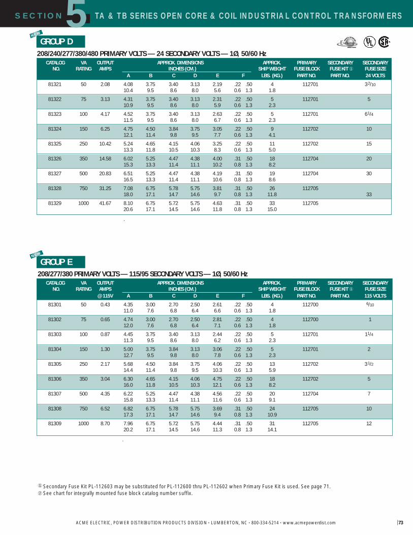
TA & TB SERIES OPEN CORE & COIL INDUSTRIAL CONTROL TRANSFORMERS5SECTION
ACME ELECTRIC, POWER DISTRIBUTION PRODUCTS DIVISION • LUMBERTON, NC • 800-334-5214 • www.acmepowerdist.com 73
208/277/380 PRIMARY VOLTS — 115/95 SECONDARY VOLTS — 1Ø, 50/60 HzGROUP E
NEW
.
� Secondary Fuse Kit PL-112603 may be substituted for PL-112600 thru PL-112602 when Primary Fuse Kit is used. See page 71.� See chart for integrally mounted fuse block catalog number suffix.
208/240/277/380/480 PRIMARY VOLTS — 24 SECONDARY VOLTS — 1Ø, 50/60 HzGROUP D
NEW
.
CATALOG VA OUTPUT APPROX. DIMENSIONS APPROX. PRIMARY SECONDARY SECONDARYNO. RATING AMPS INCHES (CM.) SHIP WEIGHT FUSE BLOCK FUSE KIT � FUSE SIZE
@ 115V A B C D E F LBS. (KG.) PART NO. PART NO. 115 VOLTS
81301 50 0.43 4.35 3.00 2.70 2.50 2.61 .22 .50 4 112700 6/1011.0 7.6 6.8 6.4 6.6 0.6 1.3 1.8
81302 75 0.65 4.74 3.00 2.70 2.50 2.81 .22 .50 4 112700 112.0 7.6 6.8 6.4 7.1 0.6 1.3 1.8
81303 100 0.87 4.45 3.75 3.40 3.13 2.44 .22 .50 5 112701 11/411.3 9.5 8.6 8.0 6.2 0.6 1.3 2.3
81304 150 1.30 5.00 3.75 3.84 3.13 3.06 .22 .50 5 112701 212.7 9.5 9.8 8.0 7.8 0.6 1.3 2.3
81305 250 2.17 5.68 4.50 3.84 3.75 4.06 .22 .50 13 112702 31/214.4 11.4 9.8 9.5 10.3 0.6 1.3 5.9
81306 350 3.04 6.30 4.65 4.15 4.06 4.75 .22 .50 18 112702 516.0 11.8 10.5 10.3 12.1 0.6 1.3 8.2
81307 500 4.35 6.22 5.25 4.47 4.38 4.56 .22 .50 20 112704 715.8 13.3 11.4 11.1 11.6 0.6 1.3 9.1
81308 750 6.52 6.82 6.75 5.78 5.75 3.69 .31 .50 24 112705 1017.3 17.1 14.7 14.6 9.4 0.8 1.3 10.9
81309 1000 8.70 7.96 6.75 5.72 5.75 4.44 .31 .50 31 112705 1220.2 17.1 14.5 14.6 11.3 0.8 1.3 14.1
CATALOG VA OUTPUT APPROX. DIMENSIONS APPROX. PRIMARY SECONDARY SECONDARYNO. RATING AMPS INCHES (CM.) SHIP WEIGHT FUSE BLOCK FUSE KIT � FUSE SIZE
A B C D E F LBS. (KG.) PART NO. PART NO. 24 VOLTS
81321 50 2.08 4.08 3.75 3.40 3.13 2.19 .22 .50 4 112701 32/1010.4 9.5 8.6 8.0 5.6 0.6 1.3 1.8
81322 75 3.13 4.31 3.75 3.40 3.13 2.31 .22 .50 5 112701 510.9 9.5 8.6 8.0 5.9 0.6 1.3 2.3
81323 100 4.17 4.52 3.75 3.40 3.13 2.63 .22 .50 5 112701 61/411.5 9.5 8.6 8.0 6.7 0.6 1.3 2.3
81324 150 6.25 4.75 4.50 3.84 3.75 3.05 .22 .50 9 112702 1012.1 11.4 9.8 9.5 7.7 0.6 1.3 4.1
81325 250 10.42 5.24 4.65 4.15 4.06 3.25 .22 .50 11 112702 1513.3 11.8 10.5 10.3 8.3 0.6 1.3 5.0
81326 350 14.58 6.02 5.25 4.47 4.38 4.00 .31 .50 18 112704 2015.3 13.3 11.4 11.1 10.2 0.8 1.3 8.2
81327 500 20.83 6.51 5.25 4.47 4.38 4.19 .31 .50 19 112704 3016.5 13.3 11.4 11.1 10.6 0.8 1.3 8.6
81328 750 31.25 7.08 6.75 5.78 5.75 3.81 .31 .50 26 11270518.0 17.1 14.7 14.6 9.7 0.8 1.3 11.8 33
81329 1000 41.67 8.10 6.75 5.72 5.75 4.63 .31 .50 33 11270520.6 17.1 14.5 14.6 11.8 0.8 1.3 15.0

TA & TB SERIES OPEN CORE & COIL INDUSTRIAL CONTROL TRANSFORMERS5SECTION
ACME ELECTRIC, POWER DISTRIBUTION PRODUCTS DIVISION • LUMBERTON, NC • 800-334-5214 • www.acmepowerdist.com74
GROUP G
� Secondary Fuse Kit PL-112603 may be substituted for PL-112600 thru PL-112602 when Primary Fuse Kit is used. See page 71.� Secondary fuse kit application for 115V only.
240/416/480/600; 230/400/460/575; 220/380/440/550; 208/500 PRIMARY VOLTS 99/120/130; 95/115/125; 91/110/120; 85/100/110 SECONDARY VOLTS 1 , 50/60 Hz
NEW
380/440/550/600 PRIMARY VOLTS 115/230 SECONDARY VOLTS 1 , 50/60 Hz
GROUP F
CATALOG VA OUTPUT APPRO DIMENSIONS APPRO PRIMAR SECONDARNO RATING AMPS INCHES CM SHIP EIGHT FUSE BLOCK FUSE SI E�
@ 115V A B C D E F LBS KG PART NO 115 VOLTS
2 54535 50 0.43 4.12 3.75 3.21 3.13 2.19 .22 .50 4 112701 6/1010.5 9.5 8.2 8.0 5.6 0.6 1.3 1.8
2 54536 100 0.87 4.56 3.75 3.21 3.13 2.31 .22 .50 5 112701 11/411.6 9.5 8.2 8.0 5.9 0.6 1.3 2.3
2 54537 150 1.30 5.00 3.75 3.21 3.13 3.06 .22 .50 10 112701 212.7 9.5 8.2 8.0 7.8 0.6 1.3 4.5
2 54538 250 2.17 5.49 4.50 3.84 3.75 3.50 .22 .50 11 112702 31/213.9 11.4 9.8 9.5 8.9 0.6 1.3 5.0
2 81197 350 3.04 6.03 4.88 4.15 4.06 4.38 .22 .50 17 112703 515.3 12.4 10.5 10.3 11.1 0.6 1.3 7.7
2 54539 500 4.35 6.76 4.88 4.15 4.06 5.75 .22 .50 23 112703 717.1 12.4 10.5 10.3 14.6 0.6 1.3 10.4
2 81240 750 6.52 7.19 6.75 5.72 5.75 3.69 .31 .50 25 112705 1018.3 17.1 14.5 14.6 9.4 0.8 1.3 11.3
2 81241 1000 8.70 7.77 6.75 5.72 5.75 4.44 .31 .50 30 112705 1219.7 17.1 14.5 14.6 11.3 0.8 1.3 13.6
CATALOG VA OUTPUT APPRO DIMENSIONS APPRO PRIMAR SECONDAR SECONDARNO RATING AMPS INCHES CM SHIP EIGHT FUSE BLOCK FUSE KIT FUSE SI E
@ 130V A B C D E F LBS KG PART NO PART NO 130 VOLTS
32403 50 0.38 4.08 3.75 3.40 3.13 2.31 .22 .50 5 112701 6/1010.4 9.5 8.6 8.0 5.9 0.6 1.3 2.3
32404 150 1.15 4.75 4.50 3.84 3.75 3.05 .22 .50 10 112702 16/1012.1 11.4 9.8 9.5 7.7 0.6 1.3 4.5
32405 250 1.92 5.58 4.65 4.15 4.06 4.06 .22 .50 16 112702 32/1014.2 11.8 10.5 10.3 10.3 0.6 1.3 7.3
32669 350 2.69 6.23 4.65 4.15 4.06 5.50 .22 .50 22 112702 415.8 11.8 10.5 10.3 14.0 0.6 1.3 10.0
32406 500 3.85 6.40 6.75 5.78 5.75 3.69 .22 .50 23 112705 61/416.3 17.1 14.7 14.6 9.4 0.6 1.3 10.4
54523 750 5.77 7.08 6.75 5.78 5.75 4.13 .31 .50 29 112705 918.0 17.1 14.7 14.6 10.5 0.8 1.3 13.2
54524 1000 7.69 8.56 6.75 5.78 5.75 4.88 .31 .50 35 112705 1221.7 17.1 14.7 14.6 12.4 0.8 1.3 15.9
2 54525 1500 11.54 6.75 7.50 7.66 6.50 5.42 .41 .81 55 112706 112601 2017.1 19.1 19.5 16.5 13.8 1.0 2.1 24.9
2 81202 2000 15.39 7.45 7.50 7.66 6.50 6.12 .41 .81 55 112706 112601 2518.9 19.1 19.5 16.5 15.5 1.0 2.1 24.9
2 81203 3000 23.08 7.02 11.92 8.83 6.75 5.75 .41 .81 70 11270717.8 30.3 22.4 17.1 14.6 1.0 2.1 31.8
2 81205 5000 38.46 7.52 11.92 9.49 6.75 6.25 .41 .81 110 11270719.1 30.3 24.1 17.1 15.9 1.0 2.1 49.9
NEW
NEW
NEW
NEW
NEW
NEW

TA & TB SERIES OPEN CORE & COIL INDUSTRIAL CONTROL TRANSFORMERSSECTION5
ACME ELECTRIC, POWER DISTRIBUTION PRODUCTS DIVISION • LUMBERTON, NC • 800-334-5214 • www.acmepowerdist.com
��Secondary Fuse Kit PL-112603 may be substituted for PL-112600 thru PL-112602 when Primary Fuse Kit is used. See page 71.
208/230/460 PRIMARY VOLTS — 115 SECONDARY VOLTS — 1Ø, 50/60 Hz
GROUP HNEW
.
600 PRIMARY VOLTS — 12/24 SECONDARY VOLTS — 1Ø, 60 HzGROUP I
CATALOG VA OUTPUT APPROX. DIMENSIONS APPROX. PRIMARYNO. RATING AMPS INCHES (CM.) SHIP WEIGHT FUSE BLOCK
@ 12V A B C D E F LBS. (KG.) PART NO.83300 50 4.17 4.13 3.00 2.59 2.50 2.30 .22 .50 4 112700
10.5 7.6 6.6 6.4 5.8 0.6 1.3 1.8
83301 100 8.33 4.90 3.00 2.59 2.50 3.35 .22 .50 4 11270012.4 7.6 6.6 6.4 8.5 0.6 1.3 1.8
83302 150 12.50 4.92 3.75 3.21 3.13 2.81 .22 .50 6 11270112.5 9.5 8.2 8.0 7.1 0.6 1.3 2.7
83303 250 20.83 5.38 4.50 3.84 3.75 3.05 .22 .50 9 11270213.7 11.4 9.8 9.5 7.7 0.6 1.3 4.1
83304 500 41.67 6.06 4.88 4.15 4.06 4.06 .22 .50 13 11270315.4 12.4 10.5 10.3 10.3 0.6 1.3 5.9
83305 750 62.50 6.43 5.25 4.47 4.38 4.00 .31 .50 21 11270416.3 13.3 11.4 11.1 10.2 0.8 1.3 9.5
83306 1000 83.33 7.30 6.75 5.72 5.75 3.69 .31 .50 24 11270518.5 17.1 14.5 14.6 9.4 0.8 1.3 10.9
CONNECTION DETAILS FOR GROUP GCONNECT TO LINE FOR RESPECTIVE VOLTAGE OUTPUT VOLTS
H1-H2 H1-H3 H1-H4 H1-H5 X1-X2 X1-X3 X1-X4
208 500 85 100 110
220 380 440 550 91 110 120
230 400 460 575 95 115 125
240 416 480 600 99 120 130
CATALOG VA OUTPUT APPROX. DIMENSIONS APPROX. PRIMARY SECONDARY SECONDARYNO. RATING AMPS INCHES (CM.) SHIP WEIGHT FUSE BLOCK FUSE KIT � FUSE SIZE
A B C D E F LBS. (KG.) PART NO. PART NO. 115 VOLTS69300 50 0.43 4.44 3.00 2.70 2.50 2.61 .22 .50 4 112700 6/10
11.3 7.6 6.8 6.4 6.6 0.6 1.3 1.8
69301 100 0.87 5.21 3.00 2.70 2.50 3.26 .22 .50 4 112700 14/1013.2 7.6 6.8 6.4 8.3 0.6 1.3 1.8
69302 150 1.30 5.10 3.75 3.40 3.13 3.06 .22 .50 7 112701 213.0 9.5 8.6 8.0 7.8 0.6 1.3 3.2
69303 250 2.17 5.38 4.50 3.84 3.75 3.50 .22 .50 11 112702 31/213.7 11.4 9.8 9.5 8.9 0.6 1.3 5.0
69304 350 3.04 5.90 4.65 4.15 4.06 3.81 .22 .50 15 112702 515.0 11.8 10.5 10.3 9.7 0.6 1.3 6.8
69305 500 4.35 6.22 5.25 4.47 4.38 4.56 .31 .50 20 112704 715.8 13.3 11.4 11.1 11.6 0.8 1.3 9.1
69306 750 6.52 6.82 6.75 5.78 5.75 3.81 .31 .50 26 112705 1017.3 17.1 14.7 14.6 9.7 0.8 1.3 11.8
69307 1000 8.70 7.96 6.75 5.78 5.75 4.63 .31 .50 33 112705 1220.2 17.1 14.7 14.6 11.8 0.8 1.3 15.0

SECTION TA & TB SERIES OPEN CORE & COIL INDUSTRIAL CONTROL TRANSFORMERS5
ACME ELECTRIC, POWER DISTRIBUTION PRODUCTS DIVISION • LUMBERTON, NC • 800-334-5214 • www.acmepowerdist.com76
600 PRIMARY VOLTS 120/240 SECONDARY VOLTS 1 , 60 HzGROUP K
240 X 480 PRIMARY VOLTS 120/240 SECONDARY VOLTS 1 , 60 HzGROUP J
NEW
.
NEW
NEW
NEW
NEW
NEW
NEW
TA SERIES PROTECTIVE DEVICES Secondary Fuse KitsFOR USE ITH INDUSTRIAL CONTROL TRANSFORMERS THROUGH 1500 VA
CATALOG NO APPRO SHIP EIGHT L K
112700 1 0.5112701 1 0.5112702 1 0.5112703 1 0.5112704 1 0.5112705 1 0.5112706 1 0.5112707 1 0.5
TB SERIES PROTECTIVE DEVICES Secondary Fuse KitsAPPRO SHIPPING T
CATALOG NO VA DESCRIPTION LBS KG
79924 1/4 1 1/4 / 1.0 0.579928 50 350 . 2 1.0 0.579929 500 750 . 2 1.0 0.579930 50 350 / 1.0 0.579931 500 1000 / 1.0 0.5
TA & TB SERIES PROTECTIVE DEVICESPrimary Fuse KitsFUSES ARE NOT INCLUDED CONSULT CATALOG FORPROPER FUSE SELECTION CATALOG NO APPRO SHIP EIGHT L K
112600 0.5 0.2
112601 0.5 0.2
112602 1 0.5
112603 1 0.5
CATALOG VA OUTPUT APPRO DIMENSIONS APPRO PRIMARNO RATING AMPS INCHES CM SHIP EIGHT FUSE BLOCK
@ 120V A B C D E F LBS KG PART NO83310 50 0.42 4.13 3.00 2.59 2.50 2.30 .22 .50 4 112700
10.5 7.6 6.6 6.4 5.8 0.6 1.3 1.883311 100 0.83 4.90 3.00 2.59 2.50 3.35 .22 .50 4 112700
12.4 7.6 6.6 6.4 8.5 0.6 1.3 1.883312 150 1.25 4.92 3.75 3.21 3.13 2.81 .22 .50 6 112701
12.5 9.5 8.2 8.0 7.1 0.6 1.3 2.783313 250 2.08 5.38 4.50 3.84 3.75 3.05 .22 .50 9 112702
13.7 11.4 9.8 9.5 7.7 0.6 1.3 4.183314 500 4.17 6.06 4.88 4.15 4.06 4.06 .22 .50 13 112703
15.4 12.4 10.5 10.3 10.3 0.6 1.3 5.983315 750 6.25 6.43 5.25 4.47 4.38 4.00 .31 .50 21 112704
16.3 13.3 11.4 11.1 10.2 0.8 1.3 9.583316 1000 8.33 7.34 6.75 5.72 5.75 3.69 .31 .50 24 112705
18.6 17.1 14.5 14.6 9.4 0.8 1.3 10.9
CATALOG VA OUTPUT APPRO DIMENSIONS APPRO PRIMARNO RATING AMPS INCHES CM SHIP EIGHT FUSE BLOCK
@ 120V A B C D E F LBS KG PART NO83210 50 0.42 4.13 3.00 2.70 2.50 2.30 .22 .50 4 112700
10.5 7.6 6.8 6.4 5.8 0.6 1.3 1.883212 100 0.83 4.90 3.00 2.70 2.50 3.35 .22 .50 4 112700
12.4 7.6 6.8 6.4 8.5 0.6 1.3 1.883213 150 1.25 4.92 3.75 3.40 3.13 2.81 .22 .50 6 112701
12.5 9.5 8.6 8.0 7.1 0.6 1.3 2.783215 250 2.08 5.38 4.50 3.84 3.75 3.05 .22 .50 9 112702
13.7 11.4 9.8 9.5 7.7 0.6 1.3 4.183218 500 4.17 6.06 5.25 4.47 4.06 4.06 .22 .50 13 112703
15.4 13.3 11.4 10.3 10.3 0.6 1.3 5.983219 750 6.25 6.43 5.25 4.47 4.38 5.30 .31 .50 21 112704
16.3 13.3 11.4 11.1 13.0 0.8 1.3 9.583220 1000 8.33 7.34 6.75 5.78 5.75 3.69 .31 .50 24 112705
18.6 17.1 14.7 14.6 9.4 0.8 1.3 10.983221 1500 12.50 8.80 6.75 5.72 5.75 5.02 .31 .50 43 112705
22.4 17.1 14.5 14.6 12.8 0.8 1.3 19.583222 2000 16.67 9.15 6.75 5.72 5.75 5.42 .31 .50 48 112705
23.2 17.1 14.5 14.6 13.8 0.8 1.3 21.883223 3000 25.00 7.00 7.50 7.66 6.50 5.55 .41 .81 51 112706
17.8 19.1 19.5 16.5 14.1 1.0 2.1 23.183224 5000 41.67 7.06 11.92 8.75 6.75 5.75 .41 .81 90 112707
17.9 30.3 22.2 17.1 14.6 1.0 2.1 40.8

5SECTION TA SERIES OPEN CORE & COIL INDUSTRIAL CONTROL TRANSFORMERS
ACME ELECTRIC, POWER DISTRIBUTION PRODUCTS DIVISION • LUMBERTON, NC • 800-334-5214 • www.acmepowerdist.com
TA Series Open Core & Coil Wiring Diagrams
X2 X1
H4H2H3H1
24V
H1 H2
240V 120V
H3 H4 H1 H2H3 H4
X2 X1
120V115110
H4H2H3H1
H1 H2
480V460440
H3 H4 H1 H2H3 H4
240V230220
X1
100V 95 90
240V230220
H2 H3H1600V575550
120V115110
X3
480V460440
H4
X2X1
240V208V
H6H1
24VX2
H2H3
H5
H4277V380V480V
X2
X1
95V
277V
208V
H4H2 H3H1
380V
115VX3
X4 X2 X3 X1
X4 X2 X3 X1
X4 X2 X3 X1
H1
230V 115V
600V
H2380V440V H3
H4
H5
550V
X2 X1
99V959185
416V400380240V
230220208
H5H2 H3H1600V575550500
X4 X3
480V460440
H4
130V125120110
120V115110100
X1
230V
208V
H4H1
460V
115VX2
H2
H3
X4 X2 X3 X1
X4 X2 X3 X1
X4 X2 X3 X1
H1
24V 12V
600V
H2
H1 H2
480V 240V
H3 H4H1 H3 H2 H4
H1 H2H3 H4
X4 X2 X3 X1
X4 X2 X3 X1
X4 X2 X3 X1
240V 120V
X4 X2 X3 X1
X4 X2 X3 X1
X4 X2 X3 X1
H1
240V 120V
600V
H2
B
D F
E
C
AE
C
D
A
BF
TA Series Open Core & Coil Dimensional Drawings

TB SERIES OPEN CORE & COIL INDUSTRIAL CONTROL TRANSFORMERSSECTION5
ACME ELECTRIC, POWER DISTRIBUTION PRODUCTS DIVISION • LUMBERTON, NC • 800-334-5214 • www.acmepowerdist.com78
TB Series Open Core & Coil Dimensional Drawings
B
E
D
AC
F
TB Series Open Core & Coil Wiring Diagrams
Group A Group B Group C
X2 X1
H4H2H3H1
24V
H1 H2
240V 120V
H3 H4 H1 H2H3 H4
X2 X1
120V115110
H4H2H3H1
H1 H2
480V460440
H3 H4 H1 H2H3 H4
240V230220
X1
100V 95 90
240V230220
H2 H3H1600V575550
120V115110
X3
480V460440
H4
X2X1
240V208V
H6H1
24VX2
H2H3
H5
H4277V380V480V
X2
X1
95V
277V
208V
H4H2 H3H1
380V
115VX3
X2 X1
99V959185
416V400380240V
230220208
H5H2 H3H1600V575550500
X4 X3
480V460440
H4
130V125120110
120V115110100
X1
230V
208V
H4H1
460V
115VX2
H2
H3
Group D
Group E Group G Group H Group J
H1 H2
480V 240V
H3 H4H1 H3 H2 H4
H1 H2H3 H4
X4 X2 X3 X1
X4 X2 X3 X1
X4 X2 X3 X1
240V 120V
NEW
NEW

5SECTION INDUSTRIAL CONTROL TRANSFORMERS
ACME ELECTRIC, POWER DISTRIBUTION PRODUCTS DIVISION • LUMBERTON, NC • 800-334-5214 • www.acmepowerdist.com
� See page 72 for electrical diagram.� See page 66 for fuse sizing information.��For secondary fuse size, multiply output amps x 1.25.
240/480/600 PRIMARY VOLTS—120/100 Secondary Volts� — 1Ø, 50/60 Hz
240 x 480 PRIMARY VOLTS—120 SECONDARY VOLTS� —1Ø, 50/60 Hz
Some specifications require installation of large control transformers, usually 1000to 5000 VA outside the control cabinet. This means the transformer must be in asheet metal enclosure instead of the usual open core and coil construction method.
Acme meets this need by providing all of the power, protection, regulation andperformance of our standard industrial control transformers in one UL -3R enclosure.These transformers are wound with copper magnet wire, deliver full nameplatecapacity, and provide the high regulation required in control applications.
Voltage combinations available are: 240 x 480V primary, 120V secondary and240/480/600V primary, 120/100V secondary. Ratings available are 1000, 2000,3000 and 5000 VA. All units are UL listed, CSA certified, and covered by Acme sexclusive 10-year limited warranty.
FEATURES� Fully encapsulated and enclosed. � 55° C temperature rise, 155°C insulation.� Copper windings.� 1000, 2000, 3000, 5000 and 10000 VA sizes.� Voltage regulation exceeds NEMA requirements.� UL and UL-3R listed.� CSA certified.� 10-year limited warranty.
Industrial Control Transformers for Harsh EnvironmentsDesigned for Control Panels where Internal Installation of Control Transformers is prohibited.
D
H
W
GROUP L
GROUP M
APPROX. DIMENSIONS APPROX. SHIP ELECTRICALCATALOG VA OUTPUT INCHES (CM.) WEIGHT CONNECTION
NO. RATING AMPS H W D LBS. (KG.) DIAGRAM���1 53929 2000 16.67 14.77 10.31 7.13 80
37.5 26.2 18.1 36.31 53930 3000 25.00 13.85 13.25 10.19 130
35.2 33.7 25.9 59.01 53931 5000 41.67 13.85 13.25 10.19 140
35.2 33.7 25.9 63.5
APPRO DIMENSIONS APPRO SHIP ELECTRICALCATALOG VA OUTPUT INCHES CM EIGHT CONNECTION
NO RATING AMPS H D LBS KG DIAGRAM���
1 81217 1000 8.33 13.10 10.31 7.13 5533.3 26.2 18.1 24.9
1 81219 2000 16.67 14.77 10.31 7.13 8037.5 26.2 18.1 36.3
1 81220 3000 25.00 14.77 10.31 7.13 10037.5 26.2 18.1 45.4
1 81221 5000 41.67 13.85 13.25 10.19 14035.2 33.7 25.9 63.5
1 81223 10000 83.3 16.47 13.88 12.94 30841.8 35.3 32.9 139.7

AE/CE SERIES INDUSTRIAL CONTROL TRANSFORMERS
80
AE/CE Series Industrial Control Transformers
SECTION5
ACME ELECTRIC, POWER DISTRIBUTION PRODUCTS DIVISION • LUMBERTON, NC • 800-334-5214 • www.acmepowerdist.com
The Acme Electric AE and CE Series Industrial ControlTransformers are designed specifically for machine tool controlcircuit applications. These transformers have the ability tohandle potentially damaging high in-rush currents that occurwhen electromagnetic components are energized, withoutsacrificing the required stable output voltage. Designed tomeet or exceed the demands of international standards,combined with the full breadth of product offering, the AEand CE Series Transformers from Acme Electric are the idealsolution for your industrial control applications.
Cooler. Cleaner. More Compact.The AE and CE Series design improves the dissipation of theheat away from the core and coil assembly providing cooleroperation. In addition, the AE and CE Series industrial controltransformers seal the transformer s windings and internalterminations within an epoxy encapsulant encased in a durablethermoplastic end cap, protecting them from potentiallydamaging moisture, dirt and other ambient contaminants.Furthermore, Acme s compact design helps minimize themounting footprint, providing more flexibility in applicationswhere space is at a premium.
FEATURES & BENEFITS� Epoxy encapsulated design protects core & coil assembly
from potentially damaging contaminants.
� Integrally molded terminal blocks with isolation barriers to prevent arc over, terminal blocks allow full access for ringterminals for easy installation and solid termination.
� Heavy gauge steel mounting feet.
� Available factory or field installed fuse blocks provideintegral fusing on the primary or primary and secondary.
� Dual labeling for easy product identification when equipped with a fuse block.
� 50-750 VA, 50/60 Hz.
� UL and cUL Listed, CE Marked (CE Series only).
� Ten-year limited warranty.
� 55°C Temperature Rise.
� 105°C Insulation Class.
CE Series for Global ApplicationsAcmes CE Series Encapsulated Industrial Control Transformerscarry the CE mark, indicating it complies with the requirementsestablished by the International Electrotechnical Commission
(IEC) for use of control circuit transformers in thecountries of the European Union. Regulations
that apply to control transformers includeLow Voltage Directive 73/23/EEC andElectromagnetic Compatibility (EMC)Directive 89/336/EEC.
NEW

AE/CE SERIES INDUSTRIAL CONTROL TRANSFORMERSSECTION5
ACME ELECTRIC, POWER DISTRIBUTION PRODUCTS DIVISION • LUMBERTON, NC • 800-334-5214 • www.acmepowerdist.com
Integrally mounted fuse blocks available in standard and touch-proof
(CE Series) style.
Dual labels for identification
of fused modules
Integrally molded terminal blocks with combination slotted/phillips screws. Isolation barriersprotect against arc over while able to accommodate
a full ring terminal.
CE Series offers touch-proof terminals,isolating live contacts for
additional safety.
Epoxy encapsulated copper windingsand internal terminations, providing isolation from external contaminants
and physical damage.
FEATURES

AE/CE INDUSTRIAL CONTROL TRANSFORMERSSECTION5
ACME ELECTRIC, POWER DISTRIBUTION PRODUCTS DIVISION • LUMBERTON, NC • 800-334-5214 • www.acmepowerdist.com
120 x 240 PRIMARY VOLTS 24 SECONDARY VOLTS 1 , 50/60 Hz
240 x 480 PRIMARY VOLTS 24 SECONDARY VOLTS 1 , 50/60 Hz
C
SELECTION CHARTS AE SERIES
200/220/440, 208/230/460, 240/480 PRIMARY VOLTS 23/110, 24/115, 25/120 SECONDARY VOLTS 1 , 50/60 Hz VA APPRO DIMENSIONS INCHES CM MOUNTING SLOT APPRO
RATING CATALOG NUMBER A B C D E F SHIPPING T
50 02 0050 3.28 8.3 3.00 7.6 2.78 7.0 2.25 5.7 2.53 6.4 .20 .40 0.5 1.0 3.0 1.4
75 02 0075 3.28 8.3 3.00 7.6 3.09 7.8 2.53 6.4 2.81 7.1 .20 .40 0.5 1.0 4.0 1.8
100 02 0100 3.28 8.3 3.41 8.6 3.41 8.6 2.53 6.4 3.13 7.9 .20 .40 0.5 1.0 4.0 1.8
150 02 0150 4.03 10.2 3.75 9.5 3.41 8.6 3.28 8.3 3.13 7.9 .20 .40 0.5 1.0 7.0 3.2
250 02 0250 4.38 11.1 4.50 11.4 4.03 10.2 3.75 9.5 3.75 9.5 .20 .40 0.5 1.0 9.0 4.1
300 02 0300 5.13 13.0 4.50 11.4 4.97 12.6 3.88 9.8 4.38 11.1 .31 .69 0.8 1.7 11.0 5.0
350 02 0350 5.25 13.3 4.50 11.4 4.97 12.6 4.16 10.5 4.38 11.1 .31 .69 0.8 1.7 13.0 5.9
500 02 0500 6.31 16.0 5.25 13.3 4.97 12.6 5.25 13.3 4.38 11.1 .31 .69 0.8 1.7 19.0 8.6
750 02 0750 6.81 17.3 5.25 13.3 4.97 12.6 5.75 14.6 4.38 11.1 .31 .69 0.8 1.7 27.0 12.2
GROUP I
GROUP II
GROUP III
NEW
NEW
NEW
VA APPRO DIMENSIONS INCHES CM MOUNTING SLOT APPRORATING CATALOG NUMBER A B C D E F SHIPPING T
50 01 0050 2.69 6.8 3.00 7.6 2.81 7.1 2.03 5.1 2.53 6.4 .20 .40 0.5 1.0 2.50 1.1
75 01 0075 3.22 8.1 3.00 7.6 2.81 7.1 2.53 6.4 2.53 6.4 .20 .40 0.5 1.0 3.50 1.6
100 01 0100 3.28 8.3 3.41 8.6 3.09 7.8 2.41 6.1 2.81 7.1 .20 .40 0.5 1.0 4.05 1.8
150 01 0150 3.88 9.8 3.78 9.6 3.41 8.6 2.97 7.5 3.13 7.9 .20 .40 0.5 1.0 6.50 2.9
250 01 0250 4.13 10.4 4.50 11.4 3.84 9.7 2.94 7.4 3.75 9.5 .20 .40 0.5 1.0 9.25 4.2
350 01 0350 5.00 12.7 4.50 11.4 3.84 9.7 3.78 9.6 3.75 9.5 .20 .40 0.5 1.0 12.75 5.8
500 01 0500 5.53 14.0 5.25 13.3 4.66 11.8 4.16 10.5 4.38 11.1 .31 .69 0.8 1.7 19.00 8.6
750 01 0750 6.81 17.3 5.25 13.3 4.66 11.8 5.75 14.6 4.38 11.1 .31 .69 0.8 1.7 26.00 11.8
VA APPRO DIMENSIONS INCHES CM MOUNTING SLOT APPRORATING CATALOG NUMBER A B C D E F SHIPPING T
50 03 0050 2.69 6.8 3.00 7.6 2.81 7.1 2.03 5.1 2.53 6.4 .20 .40 0.5 1.0 2.5 1.1
75 03 0075 3.22 8.1 3.00 7.6 2.81 7.1 2.53 6.4 2.53 6.4 .20 .40 0.5 1.0 3.5 1.6
100 03 0100 3.28 8.3 3.41 8.6 3.09 7.8 2.41 6.1 2.81 7.1 .20 .40 0.5 1.0 4.0 1.8
150 03 0150 3.88 9.8 3.84 9.7 3.41 8.6 2.97 7.5 3.13 7.9 .20 .40 0.5 1.0 6.5 2.9
250 03 0250 4.13 10.4 4.50 11.4 3.84 9.7 2.94 7.4 3.75 9.5 .20 .40 0.5 1.0 9.2 4.2
350 03 0350 5.00 12.7 4.50 11.4 3.84 9.7 3.78 9.6 3.75 9.5 .20 .40 0.5 1.0 12.7 5.8
500 03 0500 5.53 14.0 5.25 13.3 4.66 11.8 4.16 10.5 4.34 11.0 .31 .69 0.8 1.7 19.0 8.6
750 03 0750 6.81 17.3 5.25 13.3 4.66 11.8 5.75 14.6 4.38 11.1 .31 .69 0.8 1.7 26.0 11.8

AE/CE SERIES INDUSTRIAL CONTROL TRANSFORMERS
83
SECTION5
ACME ELECTRIC, POWER DISTRIBUTION PRODUCTS DIVISION • LUMBERTON, NC • 800-334-5214 • www.acmepowerdist.com
240 x 480, 230 x 460, 220 x 440 PRIMARY VOLTS —120/115/110 SECONDARY VOLTS –– 1Ø, 50/60 Hz
208/230/460 PRIMARY VOLTS –– 115 SECONDARY VOLTS –– 1Ø, 50/60 Hz
CGROUP VI
GROUP VII
NEW
NEW
VA APPROX. DIMENSIONS INCHES (CM.) MOUNTING SLOT APPROX.RATING CATALOG NUMBER A B C D E F SHIPPING WT
50 06 0050 2.69 6.8 3.00 7.6 2.81 7.1 2.03 5.1 2.53 6.4 .20 .40 0.5 1.0 2.5 1.1
75 06 0075 3.22 8.1 3.00 7.6 2.81 7.1 2.53 6.4 2.53 6.4 .20 .40 0.5 1.0 3.5 1.6
100 06 0100 3.28 8.3 3.41 8.6 3.09 7.8 2.41 6.1 2.81 7.1 .20 .40 0.5 1.0 4.0 1.8
150 06 0150 3.88 9.8 3.84 9.7 3.41 8.6 2.97 7.5 3.13 7.5 .20 .40 0.5 1.0 6.5 2.9
250 06 0250 4.13 10.4 4.50 11.4 3.84 9.7 2.94 7.4 3.75 9.5 .20 .40 0.5 1.0 9.2 4.2
350 06 0350 5.00 12.7 4.50 11.4 3.84 9.7 3.78 9.6 3.75 9.5 .20 .40 0.5 1.0 12.7 5.8
500 06 0500 5.53 14.0 5.25 13.3 4.66 11.8 4.16 10.5 4.34 11.0 .31 .69 0.8 1.7 19.0 8.6
750 06 0750 6.81 17.3 5.25 13.3 4.66 11.8 5.75 14.6 4.31 10.9 .31 .69 0.8 1.7 26.0 11.8
VA APPROX. DIMENSIONS INCHES (CM.) MOUNTING SLOT APPROX.RATING CATALOG NUMBER A B C D E F SHIPPING WT
50 07 0050 2.84 7.2 3.00 7.6 2.81 7.1 2.16 5.4 2.53 6.4 .20 .40 0.5 1.0 2.6 1.2
100 07 0100 3.41 6.6 3.41 8.6 3.09 7.8 2.69 6.8 2.81 7.1 .20 .40 0.5 1.0 4.2 1.9
150 07 0150 3.88 9.8 3.75 9.5 3.41 8.6 3.09 7.8 3.09 7.8 .20 .40 0.5 1.0 6.7 3.1
250 07 0250 4.16 10.5 4.50 11.4 4.03 10.2 3.28 8.3 3.75 9.5 .20 .40 0.5 1.0 9.5 4.3
350 07 0350 5.19 13.1 4.50 11.4 4.03 10.2 4.38 11.1 3.75 9.5 .20 .40 0.5 1.0 13.4 6.1
500 07 0500 5.88 14.9 5.25 13.3 4.66 11.8 4.78 12.1 4.38 11.1 .31 .69 0.8 1.7 19.0 8.6
750 07 0750 6.81 17.3 5.25 13.3 4.66 11.8 5.75 14.6 4.38 11.1 .31 .69 0.8 1.7 27.0 12.2
230/460/575 PRIMARY VOLTS –– 95/115 SECONDARY VOLTS –– 1Ø, 50/60 HzGROUP XII
NEW
VA APPROX. DIMENSIONS INCHES (CM.) MOUNTING SLOT APPROX.RATING CATALOG NUMBER A B C D E F SHIPPING WT
50 12 0050 2.88 7.3 3.00 7.6 2.81 7.1 2.19 5.5 2.53 6.4 .20 .40 0.5 1.0 2.6 1.2
100 12 0100 3.59 9.1 3.41 8.6 3.09 7.8 2.88 7.3 2.81 7.1 .20 .40 0.5 1.0 4.2 1.9
150 12 0150 3.94 10.0 3.78 9.6 3.41 8.6 3.28 8.3 3.09 7.8 .20 .40 0.5 1.0 6.8 3.1
250 12 0250 4.16 10.5 4.50 11.4 4.03 10.2 3.22 8.1 3.75 9.5 .20 .40 0.5 1.0 9.5 4.3
350 12 0350 5.00 12.7 4.50 11.4 4.03 10.2 3.69 9.3 4.31 10.9 .20 .40 0.5 1.0 13.2 6.0
500 12 0500 5.84 14.8 5.25 13.3 4.66 11.8 4.66 11.8 4.38 11.1 .31 .69 0.8 1.7 19.2 8.7
750 12 0750 6.81 17.3 5.25 13.3 4.66 11.8 5.81 14.7 4.38 11.1 .31 .69 0.8 1.7 27.0 12.2

AE/CE SERIES INDUSTRIAL CONTROL TRANSFORMERSSECTION5
ACME ELECTRIC, POWER DISTRIBUTION PRODUCTS DIVISION • LUMBERTON, NC • 800-334-5214 • www.acmepowerdist.com
240 x 480 PRIMARY VOLTS 24 SECONDARY VOLTS 1 , 50/60 HzGROUP IIIC
VA APPRO DIMENSIONS INCHES CM MOUNTING SLOT APPRORATING CATALOG NUMBER A B C D E F SHIPPING T
50 03 0050 3.00 7.6 3.00 7.6 2.81 7.1 2.25 5.7 2.53 6.4 .20 .40 0.5 1.0 2.5 1.1
75 03 0075 3.28 8.3 3.28 8.3 2.81 7.1 2.25 5.7 2.81 7.1 .20 .40 0.5 1.0 3.5 1.6
100 03 0100 3.28 8.3 3.75 9.5 3.09 7.8 2.53 6.4 3.13 7.9 .20 .40 0.5 1.0 4.0 1.8
150 03 0150 3.88 9.8 4.50 11.4 3.47 8.8 2.53 6.4 3.75 9.5 .20 .40 0.5 1.0 6.5 2.9
250 03 0250 4.13 10.4 4.50 11.4 4.03 10.2 3.22 8.1 3.75 9.5 .20 .40 0.5 1.0 9.2 4.2
350 03 0350 5.00 12.7 5.25 13.3 4.03 10.2 3.75 9.5 4.38 11.1 .31 .69 0.8 1.7 12.7 5.8
500 03 0500 5.53 14.0 5.25 13.3 4.66 11.8 4.28 10.8 4.38 11.1 .31 .69 0.8 1.7 19.0 8.6
750 03 0750 7.03 17.8 5.25 13.3 4.66 11.8 5.41 13.7 4.38 11.1 .31 .69 0.8 1.7 26.0 11.8
NEW
SELECTION CHARTS CE SERIES
120 x 240 PRIMARY VOLTS 24 SECONDARY VOLTS 1 , 50/60 HzC
200/220/440, 208/230/460, 240/480 PRIMARY VOLTS 23/110, 24/115, 25/120 SECONDARY VOLTS 1 , 50/60 Hz
GROUP IC
VA APPRO DIMENSIONS INCHES CM MOUNTING SLOT APPRORATING CATALOG NUMBER A B C D E F SHIPPING T
50 01 0050 2.69 6.8 3.00 7.6 2.81 7.1 2.25 5.7 2.56 6.5 .20 .40 0.5 1.0 2.5 1.2
75 01 0075 3.22 8.1 3.41 8.6 2.81 7.1 2.25 5.7 2.88 7.3 .20 .40 0.5 1.0 3.5 1.6
100 01 0100 3.28 8.3 3.75 9.5 3.09 7.8 2.53 6.4 3.13 7.9 .20 .40 0.5 1.0 4.2 1.9
150 01 0150 3.88 9.8 4.50 11.4 3.41 8.6 2.53 6.4 3.84 9.7 .20 .40 0.5 1.0 6.6 3.0
250 01 0250 4.13 10.4 4.50 11.4 4.03 10.2 3.22 8.1 3.84 9.7 .20 .40 0.5 1.0 9.4 4.3
350 01 0350 5.00 12.7 5.25 13.3 4.03 10.2 3.75 9.5 4.50 11.4 .31 .69 0.8 1.7 13.0 5.9
500 01 0500 5.50 13.9 5.25 13.3 4.66 11.8 4.28 10.8 4.50 11.4 .31 .69 0.8 1.7 19.1 8.7
750 01 0750 7.03 17.8 5.25 13.3 4.66 11.8 5.75 14.6 4.50 11.4 .31 .69 0.8 1.7 26.6 12.1
GROUP IIC
VA APPRO DIMENSIONS INCHES CM MOUNTING SLOT APPRORATING CATALOG NUMBER A B C D E F SHIPPING T
50 02 0050 3.28 8.3 3.28 8.3 2.81 7.1 2.25 5.7 2.81 7.1 .20 .40 0.5 1.0 2.7 1.2
100 02 0100 4.03 10.2 3.75 9.5 3.13 7.9 3.22 8.1 3.16 8.0 .20 .40 0.5 1.0 4.3 1.9
150 02 0150 4.03 10.2 4.50 11.4 3.41 8.6 2.81 7.1 3.75 9.5 .20 .40 0.5 1.0 6.8 3.0
250 02 0250 4.78 12.1 4.50 11.4 4.03 10.2 4.06 10.3 3.75 9.5 .20 .40 0.5 1.0 9.7 4.4
350 02 0350 5.53 14.0 5.25 13.3 4.03 10.2 4.28 10.8 4.38 11.1 .31 .69 0.8 1.7 13.5 6.1
500 02 0500 7.25 18.4 5.25 13.3 4.69 11.9 6.00 15.2 4.38 11.1 .31 .69 0.8 1.7 19.6 8.9
750 02 0750 6.81 17.3 5.28 13.4 4.69 11.9 5.75 14.6 4.44 11.2 .31 .69 0.8 1.7 27.0 12.2
NEW
NEW

AE/CE SERIES INDUSTRIAL CONTROL TRANSFORMERS
85
SECTION5
ACME ELECTRIC, POWER DISTRIBUTION PRODUCTS DIVISION • LUMBERTON, NC • 800-334-5214 • www.acmepowerdist.com
380/400/415 PRIMARY VOLTS –– 110/220 SECONDARY VOLTS –– 1Ø, 50/60 Hz
208, 220/380/440, 230/400/460, 240/416/480 PRIMARY VOLTS ––85/100/110, 91/110/120, 95/115/125, 99/120/130 SECONDARY VOLTS –– 1Ø, 50/60 Hz
CGROUP IVC
VA APPROX. DIMENSIONS INCHES (CM.) MOUNTING SLOT APPROX.RATING CATALOG NUMBER A B C D E F SHIPPING WT
50 04 0050 3.53 8.9 3.00 7.6 2.81 7.1 2.53 6.4 2.53 6.4 .20 .40 0.5 1.0 2.6 1.2
100 04 0100 3.53 8.9 3.75 9.5 3.22 8.1 2.53 6.4 3.13 8.0 .20 .40 0.5 1.0 4.3 1.9
150 04 0150 3.53 8.9 4.34 11.0 3.41 8.6 2.53 6.4 3.75 9.5 .20 .40 0.5 1.0 6.7 3.0
250 04 0250 4.03 10.2 4.50 11.4 4.22 10.7 3.22 8.1 3.75 9.5 .20 .40 0.5 1.0 9.4 4.3
350 04 0350 4.91 12.4 4.50 11.4 4.22 10.7 4.06 10.3 4.38 11.1 .20 .40 0.5 1.0 13.0 5.9
500 04 0500 6.00 15.2 5.25 13.3 4.69 11.9 4.78 12.1 4.38 11.1 .31 .69 0.8 1.7 18.8 8.5
750 04 0750 6.81 17.3 5.25 13.3 4.69 11.9 5.75 14.6 4.38 11.1 .31 .69 0.8 1.7 26.0 11.8
VA APPROX. DIMENSIONS INCHES (CM.) MOUNTING SLOT APPROX.RATING CATALOG NUMBER A B C D E F SHIPPING WT
50 05 0050 4.03 10.2 3.41 8.6 3.09 7.8 2.47 6.2 2.81 7.1 .20 .40 0.5 1.0 2.7 1.2
150 05 0150 3.88 9.8 4.34 11.0 3.41 8.6 2.88 7.3 3.75 9.5 .20 .40 0.5 1.0 6.7 3.0
250 05 0250 5.13 13.0 4.50 11.4 4.03 10.2 4.38 11.1 3.75 9.5 .20 .40 0.5 1.0 9.5 4.3
350 05 0350 5.91 15.0 5.25 13.3 4.03 10.2 4.78 12.1 4.38 11.1 .31 .69 0.8 1.7 13.3 6.0
500 05 0500 5.91 15.0 5.25 13.3 4.66 11.8 4.63 11.7 4.38 11.1 .31 .69 0.8 1.7 19.0 8.6
750 05 0750 7.09 18.0 5.25 13.3 4.66 11.1 5.81 14.7 4.38 11.1 .31 .69 0.8 1.7 27.0 12.2
GROUP VC
NEW
NEW
240 x 480, 230 x 460, 220 x 440 PRIMARY VOLTS ––120/115/110 SECONDARY VOLTS –– 1Ø, 50/60 Hz GROUP VIC
NEW
VA APPROX. DIMENSIONS INCHES (CM.) MOUNTING SLOT APPROX.RATING CATALOG NUMBER A B C D E F SHIPPING WT
50 06 0050 3.41 8.6 3.00 7.6 2.81 7.1 2.53 6.4 2.53 6.4 .20 .40 0.5 1.0 2.6 1.2
75 06 0075 3.41 8.6 3.28 8.3 2.81 7.1 2.53 6.4 2.81 7.1 .20 .40 0.5 1.0 3.6 1.6
100 06 0100 3.41 8.6 3.75 9.5 3.09 7.8 2.53 6.4 3.13 7.9 .20 .40 0.5 1.0 4.3 1.9
150 06 0150 3.88 9.8 4.50 11.4 3.47 8.8 2.53 6.4 3.75 9.5 .20 .40 0.5 1.0 6.7 3.0
250 06 0250 4.13 10.4 4.50 11.4 4.03 10.2 3.22 8.1 3.75 9.5 .20 .40 0.5 1.0 9.4 4.3
300 06 0300 4.53 11.5 4.50 11.4 4.03 10.2 3.75 9.5 3.75 9.5 .20 .40 0.5 1.0 10.9 4.9
350 06 0350 5.00 12.7 5.25 13.3 4.03 10.2 3.75 9.5 4.38 11.1 .31 .69 0.8 1.7 13.0 5.9
500 06 0500 6.00 15.2 5.25 13.3 4.66 11.8 4.78 12.1 4.38 11.1 .31 .69 0.8 1.7 18.8 8.5
750 06 0750 6.81 17.3 5.25 13.3 4.66 11.8 5.75 14.6 4.38 11.1 .31 .69 0.8 1.7 26.0 11.8

AE/CE INDUSTRIAL CONTROL TRANSFORMERS
6
SECTION5
ACME ELECTRIC, POWER DISTRIBUTION PRODUCTS DIVISION • LUMBERTON, NC • 800-334-5214 • www.acmepowerdist.com
RECOMMENDED RATING FOR CURRENT LIMITING MIDGET FUSES
NOTE: 450 .
RECOMMENDED RATING FOR CURRENT LIMITING CLASS CC FUSES
FUSE SIZING CHARTS
PRIMARY FUSE SIZING CHARTS
SECONDARY FUSE SIZING CHARTS
CONNECTION DETAILS FOR AE05 & CE05
120 V 208 V 220 V 230 V 240 V 380 V 400 V 416 V 440 V 460 V 480 V 500 V 550 V 575 V 600 V
50 1.25 0.60 0.60 0.60 0.60 0.30 0.30 0.30 0.30 0.30 0.30 0.30 0.25 0.25 0.25
75 1.80 1.00 1.00 0.80 0.80 0.50 0.50 0.50 0.50 0.40 0.40 0.40 0.40 0.30 0.30
100 2.50 1.40 1.25 1.25 1.25 0.75 0.75 0.60 0.60 0.60 0.60 0.60 0.50 0.50 0.50
150 3.50 2.00 2.00 1.80 1.80 1.13 1.13 1.00 1.00 0.80 0.80 0.80 0.80 0.75 0.75
250 3.20 3.50 3.20 3.20 3.00 1.80 1.80 1.80 1.60 1.60 1.50 1.50 1.25 1.25 1.25
300 4.00 4.00 4.00 3.50 3.50 2.25 2.25 2.00 2.00 1.80 1.80 1.80 1.60 1.50 1.50
350 4.50 5.00 4.50 4.50 4.00 2.50 2.50 2.50 2.25 2.25 2.00 2.00 1.80 1.80 1.60
500 6.25 4.00 3.50 3.50 3.20 3.50 3.50 3.50 3.20 3.20 3.00 3.00 2.50 2.50 2.50
750 10.00 6.00 5.60 5.00 5.00 5.60 5.60 5.00 5.00 4.50 4.50 4.50 4.00 3.50 3.50
24 V 85 V 91 V 95 V 99 V 100 V 110 V 115 V 120 V 125 V 130 V
50 2.00 0.50 0.50 0.50 0.50 0.50 0.50 0.50 0.50 0.50 0.25
75 3.00 0.75 0.75 0.75
100 5.00 1.00 1.00 1.00
150 6.00 2.00 2.00 1.50 1.50 1.50 1.50 1.50 1.50 1.50 1.00
250 12.00 3.00 3.00 3.00 3.00 3.00 2.00 2.00 2.00 2.00 2.00
300 3.00 3.00 3.00
350 15.00 5.00 4.00 4.00 4.00 4.00 3.00 3.00 3.00 3.00 3.00
500 25.00 6.00 6.00 6.00 6.00 6.00 5.00 5.00 5.00 5.00 4.00
750 35.00 10.00 10.00 8.00 8.00 8.00 8.00 8.00 6.00 6.00 6.00
H1 H2 H1 H3 H1 H4 1 2 1 3 1 4
208 85 100 110
220 380 440 91 110 120
230 400 460 95 115 125
240 416 480 99 120 130
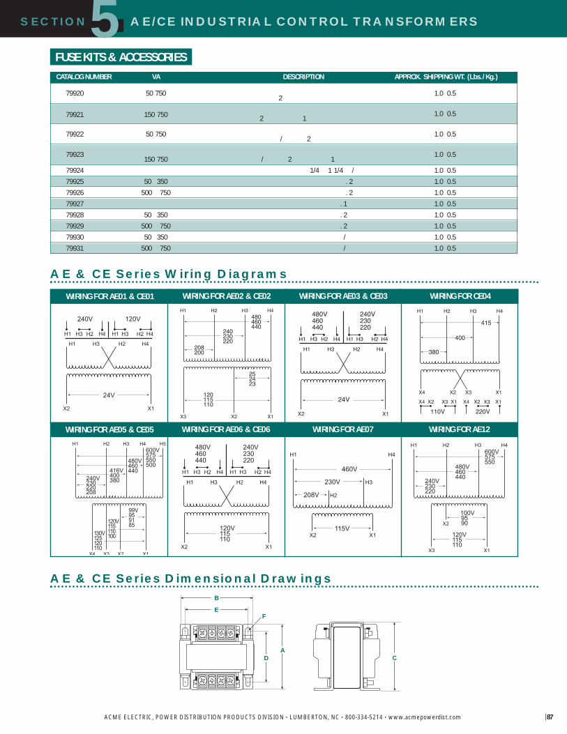
87
SECTION AE/CE INDUSTRIAL CONTROL TRANSFORMERS5
ACME ELECTRIC, POWER DISTRIBUTION PRODUCTS DIVISION • LUMBERTON, NC • 800-334-5214 • www.acmepowerdist.com
WIRING FOR AE01 & CE01 WIRING FOR AE02 & CE02 WIRING FOR AE03 & CE03 WIRING FOR CE04
WIRING FOR AE05 & CE05 WIRING FOR AE06 & CE06 WIRING FOR AE07 WIRING FOR AE12
X2 X1
H4H2H3H1
24V
H1 H2
240V 120V
H3 H4 H1 H2H3 H4
208200
H2 H3H1480460440
240230220
H4
252423
X2 X1
120115110
X3 X2 X1
24V
H4H2H3H1
H1 H2
480V460440
H3 H4 H1 H2H3 H4
240V230220
X1X3X2X4
X4 X3
220V
X2 X1X4 X3X2 X1
110V
380
H2 H3H1
415
400
H4
X2 X1
99V959185
416V400380240V
230220208
H5H2 H3H1600V575550500
X4 X3
480V460440
H4
130V125120110
120V115110100
X2 X1
120V115110
H4H2H3H1
H1 H2
480V460440
H3 H4 H1 H2H3 H4
240V230220
X1
230V
208V
H4H1
460V
115VX2
H2
H3
X1
100V 95 90
240V230220
H2 H3H1600V575550
120V115110
X3
480V460440
H4
X2
FUSE KITS & ACCESSORIES
AE & CE Series Wiring Diagrams
AE & CE Series Dimensional DrawingsB
E
DA
C
F
CATALOG NUMBER VA DESCRIPTION APPROX. SHIPPING WT. (Lbs./ Kg.)
79920 50 750 1.0 0.52
79921 150 750 1.0 0.52 1
79922 50 750 1.0 0.5/ 2
79923 1.0 0.5150 750 / 2 179924 1/4 1 1/4 / 1.0 0.579925 50 350 . 2 1.0 0.579926 500 750 . 2 1.0 0.579927 . 1 1.0 0.579928 50 350 . 2 1.0 0.579929 500 750 . 2 1.0 0.579930 50 350 / 1.0 0.579931 500 750 / 1.0 0.5

FINGER/GUARD INDUSTRIAL CONTROL TRANSFORMERS
88
SECTION5
ACME ELECTRIC, POWER DISTRIBUTION PRODUCTS DIVISION • LUMBERTON, NC • 800-334-5214 • www.acmepowerdist.com
The Acme FINGER/GUARD® line ofTouch-Protected Industrial ControlTransformers offers the most advancedand versatile design concepts availableto the marketplace today.
They are designed to meet Acme s rigidstandards for mechanical durability aswell as surpass Agency and Industryelectrical standards.The FINGER/GUARD®
line is designed for all control applicationsand features integrally installed, durablemolded plastic terminations designed toprotect against contact with live compo-nents. No slip-on plastic covers to bebroken, lost or misplaced.
All F INGER/GUARD® products usecopper windings, high-permeabilitysilicon steel cores and 130 degree C(Class B) insulation. All FINGER/GUARD®
products meet or exceed ANSI, IEC andNEMA standards. They are third partywitness tested and are UL Listed (FileE79947), CSA Certified (File 7357) andCE Marked (to EN60742)...ON ALLSIZES. The product is suitable for both 50and 60 Hertz applications and is availablein sizes ranging from 50 VA to 3000 VA.
FEATURES� Constructed with high quality silicon
steel lamination to minimize core losses and increase efficiency.
� Designs incorporate precision woundcoils for improved regulation.
� Copper windings on all groups.
� 50 VA through 3000 VA sizes, 50/60 Hz.
� 130°C (Class B) Insulation 80°Ctemperature rise.
� Voltage regulation exceeds NEMArequirements.
� UL Listed, CSA Certified and CE Marked.
� Attractive finish, nameplate, and designfeatures enhance the end product.
� Ten-year limited warranty.
� Smaller, lighter weight design.
FINGER/GUARD® Industrial Control Transformers
CE Marking(Conformité Européene)The CE Marking, standing for Conformité Européene, is a European Mark ofconformity indicating that a product or system to which it is applied, complieswith European law (Directives) regulating a necessary level of protection inEurope with respect to safety, health, environmental and consumer protection;however, it is not intended as a guarantee of quality for the consumer. The CEMarking must be applied to products being placed on the European market.The CE Marking does allow a product to be moved freely within the internalmarket of the European Union.
The Directives that apply to Control or Power Distribution Transformers are:
Low Voltage Directive, 73/23/EEC effective January 1, 1997
Electromagnetic Compatibility (EMC) Directive, 89/336/EEC effective January 1, 1996
The stringent testing required to obtain a third party certification mark in manycases is significantly more rigid than domestic requirements. This ensures thatnot only the Acme FINGER/GUARD® product, but all of our CEMarked products are designed to meet a higher level of safetystandards than non-CE Marked products.
All Acme transformers are manufactured in a facilitycertified by Underwriters Laboratories to ISO-9001.
Durable molded plastic terminal is designed for protection against contact
ith live components
Eas to read nameplateclearl identifies important data
Wide range of primar andsecondar voltages
Eas access front opening interminal makes for fast ireconnections ith one scre

FINGER/GUARD INDUSTRIAL CONTROL TRANSFORMERSSECTION5
ACME ELECTRIC, POWER DISTRIBUTION PRODUCTS DIVISION • LUMBERTON, NC • 800-334-5214 • www.acmepowerdist.com
240/416/480/600; 230/400/460/575; 220/380/440/550; 208/500 PRIMARY VOLTS99/120/130; 95/115/125; 91/110/120; 85/100/110 SECONDARY VOLTS 50/60 Hz
240 X 480, 230 X 460, 220 X 440 PRIMARY VOLTS 120/115/110 SECONDARY VOLTS 50/60 Hz
120 X 240 PRIMARY VOLTS 24 SECONDARY VOLTS 50/60 Hz
SELECTION CHARTS
GROUP A
GROUP B
GROUP C
CATALOG VA EUROPEAN APPRO DIMENSIONS INCHES CM APPRONO RATING RATING A B C D E F SHIP EIGHT LBS K
3 50 50 50 2.59 6.6 3.75 9.5 3.64 9.2 3.13 8.0 1.70 4.3 .22 .50 0.6 1.3 5 2.3
3 150 150 150 3.31 8.4 4.50 11.4 4.15 10.5 3.75 9.5 2.18 5.5 .22 .50 0.6 1.3 8 3.6
3 250 250 250 3.61 9.2 4.88 12.4 4.46 11.3 4.06 10.3 2.33 5.9 .22 .50 0.6 1.3 11 5.0
3 350 350 345 4.69 11.9 4.88 12.4 4.46 11.3 4.06 10.3 3.48 8.8 .22 .50 0.6 1.3 17 7.7
3 500 500 490 4.39 11.2 6.75 17.1 6.03 15.3 5.75 14.6 2.48 6.3 .31 .50 0.8 1.3 22 10.0
3 750 750 720 5.18 13.2 6.75 17.1 6.03 15.3 5.75 14.6 3.31 8.4 .31 .50 0.8 1.3 30 13.6
3 1000 1000 870 6.18 15.7 6.75 17.1 6.03 15.3 5.75 14.6 4.30 10.9 .31 .50 0.8 1.3 39 17.7
3 1500 1500 1290 6.26 15.9 7.50 19.1 6.68 17.0 6.50 16.5 5.26 13.4 .41 .81 1.0 2.1 51 23.1
3 2000 2000 1680 7.76 19.7 7.50 19.1 7.70 19.6 6.50 16.5 6.75 17.1 .41 .81 1.0 2.1 66 29.9
3 3000 3000 2465 8.88 22.6 11.92 30.3 8.83 22.4 6.75 17.1 5.75 14.6 .41 .81 1.0 2.1 70 31.8
R G IC CE01 :CE S I C T
50 750 VAS P 84
R G VIC CE06 :CE S I C T
50 750 VAS P 85
CATALOG VA EUROPEAN APPRO DIMENSIONS INCHES CM APPRONO RATING RATING A B C D E F SHIP EIGHT LBS K
1 50
1 75
1 100
1 150
1 250
1 350
1 500
1 750
1 1000 1000 870 4.76 12.1 6.75 17.1 6.03 15.3 5.75 14.6 2.86 7.3 .31 .50 0.8 1.3 26 11.8
CATALOG VA EUROPEAN APPRO DIMENSIONS INCHES CM APPRONO RATING RATING A B C D E F SHIP EIGHT LBS K
2 50
2 75
2 100
2 150
2 250
2 300
2 350
2 500
2 750
2 1000 1000 870 4.76 12.1 6.75 17.1 6.03 15.3 5.75 14.6 2.86 7.3 .31 .50 0.8 1.3 26 11.8
2 1500 1500 1290 6.01 15.3 6.75 17.1 6.03 15.3 5.75 14.6 4.13 10.5 .31 .50 0.8 1.3 38 17.2
2 2000 2000 1680 6.51 16.5 6.75 17.1 6.03 15.3 5.75 14.6 4.63 11.8 .31 .50 0.8 1.3 44 20.0
2 3000 3000 2465 7.44 18.9 7.50 19.1 6.68 17.0 6.50 16.5 6.47 16.4 .41 .81 1.0 2.1 60 27.2
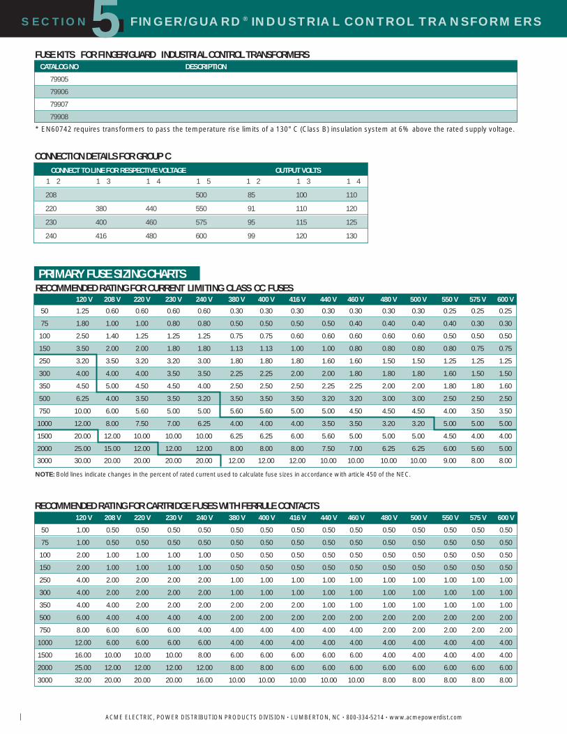
FINGER/GUARD® INDUSTRIAL CONTROL TRANSFORMERSSECTION5
ACME ELECTRIC, POWER DISTRIBUTION PRODUCTS DIVISION • LUMBERTON, NC • 800-334-5214 • www.acmepowerdist.com
120 V 208 V 220 V 230 V 240 V 380 V 400 V 416 V 440 V 460 V 480 V 500 V 550 V 575 V 600 V
50 1.25 0.60 0.60 0.60 0.60 0.30 0.30 0.30 0.30 0.30 0.30 0.30 0.25 0.25 0.25
75 1.80 1.00 1.00 0.80 0.80 0.50 0.50 0.50 0.50 0.40 0.40 0.40 0.40 0.30 0.30
100 2.50 1.40 1.25 1.25 1.25 0.75 0.75 0.60 0.60 0.60 0.60 0.60 0.50 0.50 0.50
150 3.50 2.00 2.00 1.80 1.80 1.13 1.13 1.00 1.00 0.80 0.80 0.80 0.80 0.75 0.75
250 3.20 3.50 3.20 3.20 3.00 1.80 1.80 1.80 1.60 1.60 1.50 1.50 1.25 1.25 1.25
300 4.00 4.00 4.00 3.50 3.50 2.25 2.25 2.00 2.00 1.80 1.80 1.80 1.60 1.50 1.50
350 4.50 5.00 4.50 4.50 4.00 2.50 2.50 2.50 2.25 2.25 2.00 2.00 1.80 1.80 1.60
500 6.25 4.00 3.50 3.50 3.20 3.50 3.50 3.50 3.20 3.20 3.00 3.00 2.50 2.50 2.50
750 10.00 6.00 5.60 5.00 5.00 5.60 5.60 5.00 5.00 4.50 4.50 4.50 4.00 3.50 3.50
1000 12.00 8.00 7.50 7.00 6.25 4.00 4.00 4.00 3.50 3.50 3.20 3.20 5.00 5.00 5.00
1500 20.00 12.00 10.00 10.00 10.00 6.25 6.25 6.00 5.60 5.00 5.00 5.00 4.50 4.00 4.00
2000 25.00 15.00 12.00 12.00 12.00 8.00 8.00 8.00 7.50 7.00 6.25 6.25 6.00 5.60 5.00
3000 30.00 20.00 20.00 20.00 20.00 12.00 12.00 12.00 10.00 10.00 10.00 10.00 9.00 8.00 8.00
PRIMARY FUSE SIZING CHARTSRECOMMENDED RATING FOR CURRENT LIMITING CLASS CC FUSES
NOTE: Bold lines indicate changes in the percent of rated current used to calculate fuse sizes in accordance with article 450 of the NEC.
CONNECTION DETAILS FOR GROUP C
RECOMMENDED RATING FOR CARTRIDGE FUSES WITH FERRULE CONTACTS
CONNECT TO LINE FOR RESPECTIVE VOLTAGE OUTPUT VOLTS1 2 1 3 1 4 1 5 1 2 1 3 1 4
208 500 85 100 110
220 380 440 550 91 110 120
230 400 460 575 95 115 125
240 416 480 600 99 120 130
FUSE KITS FOR FINGER/GUARD INDUSTRIAL CONTROL TRANSFORMERS
* EN60742 requires transformers to pass the temperature rise limits of a 130° C (Class B) insulation system at 6% above the rated supply voltage.
120 V 208 V 220 V 230 V 240 V 380 V 400 V 416 V 440 V 460 V 480 V 500 V 550 V 575 V 600 V
50 1.00 0.50 0.50 0.50 0.50 0.50 0.50 0.50 0.50 0.50 0.50 0.50 0.50 0.50 0.50
75 1.00 0.50 0.50 0.50 0.50 0.50 0.50 0.50 0.50 0.50 0.50 0.50 0.50 0.50 0.50
100 2.00 1.00 1.00 1.00 1.00 0.50 0.50 0.50 0.50 0.50 0.50 0.50 0.50 0.50 0.50
150 2.00 1.00 1.00 1.00 1.00 0.50 0.50 0.50 0.50 0.50 0.50 0.50 0.50 0.50 0.50
250 4.00 2.00 2.00 2.00 2.00 1.00 1.00 1.00 1.00 1.00 1.00 1.00 1.00 1.00 1.00
300 4.00 2.00 2.00 2.00 2.00 1.00 1.00 1.00 1.00 1.00 1.00 1.00 1.00 1.00 1.00
350 4.00 4.00 2.00 2.00 2.00 2.00 2.00 2.00 1.00 1.00 1.00 1.00 1.00 1.00 1.00
500 6.00 4.00 4.00 4.00 4.00 2.00 2.00 2.00 2.00 2.00 2.00 2.00 2.00 2.00 2.00
750 8.00 6.00 6.00 6.00 4.00 4.00 4.00 4.00 4.00 4.00 2.00 2.00 2.00 2.00 2.00
1000 12.00 6.00 6.00 6.00 6.00 4.00 4.00 4.00 4.00 4.00 4.00 4.00 4.00 4.00 4.00
1500 16.00 10.00 10.00 10.00 8.00 6.00 6.00 6.00 6.00 6.00 4.00 4.00 4.00 4.00 4.00
2000 25.00 12.00 12.00 12.00 12.00 8.00 8.00 6.00 6.00 6.00 6.00 6.00 6.00 6.00 6.00
3000 32.00 20.00 20.00 20.00 16.00 10.00 10.00 10.00 10.00 10.00 8.00 8.00 8.00 8.00 8.00
CATALOG NO DESCRIPTION
79905
79906
79907
79908

FINGER/GUARD INDUSTRIAL CONTROL TRANSFORMERS
91
SECTION5
ACME ELECTRIC, POWER DISTRIBUTION PRODUCTS DIVISION • LUMBERTON, NC • 800-334-5214 • www.acmepowerdist.com
SECONDARY FUSE SIZING CHARTSRECOMMENDED RATING FOR CURRENT LIMITING MIDGET FUSES
RECOMMENDED RATING FOR CARTRIDGE FUSES WITH FERRULE CONTACTS
24 V 85 V 91 V 95 V 99 V 100 V 110 V 115 V 120 V 125 V 130 V50 2.00 0.50 0.50 0.50 0.50 0.50 0.50 0.50 0.50 0.50 0.25
75 3.00 0.75 0.75 0.75
100 5.00 1.00 1.00 1.00
150 6.00 2.00 2.00 1.50 1.50 1.50 1.50 1.50 1.50 1.50 1.00
250 12.00 3.00 3.00 3.00 3.00 3.00 2.00 2.00 2.00 2.00 2.00
300 3.00 3.00 3.00
350 15.00 5.00 4.00 4.00 4.00 4.00 3.00 3.00 3.00 3.00 3.00
500 25.00 6.00 6.00 6.00 6.00 6.00 5.00 5.00 5.00 5.00 4.00
750 35.00 10.00 10.00 8.00 8.00 8.00 8.00 8.00 6.00 6.00 6.00
1000 50.00 12.00 12.00 12.00 12.00 12.00 10.00 10.00 10.00 10.00 8.00
1500 20.00 20.00 15.00 15.00 15.00 15.00 15.00 15.00 15.00 12.00
2000 25.00 25.00 25.00 25.00 25.00 20.00 20.00 20.00 20.00 15.00
3000 40.00 40.00 35.00 35.00 35.00 30.00 30.00 30.00 30.00 25.00
24 V 85 V 91 V 95 V 99 V 100 V 110 V 115 V 120 V 125 V 130 V50 4.00 1.00 1.00 1.00 1.00 1.00 0.50 0.50 0.50 0.50 0.50
75 4.00 1.00 1.00 1.00
100 6.00 1.00 1.00 1.00
150 8.00 2.00 2.00 2.00 2.00 2.00 2.00 2.00 2.00 2.00 2.00
250 12.00 4.00 4.00 4.00 4.00 4.00 4.00 4.00 4.00 4.00 2.00
300 4.00 4.00 4.00
350 16.00 6.00 4.00 4.00 4.00 4.00 4.00 4.00 4.00 4.00 4.00
500 25.00 6.00 6.00 6.00 6.00 6.00 6.00 6.00 6.00 6.00 4.00
750 32.00 10.00 10.00 8.00 8.00 8.00 8.00 8.00 8.00 8.00 6.00
1000 50.00 12.00 12.00 12.00 12.00 12.00 10.00 10.00 10.00 10.00 8.00
1500 20.00 20.00 16.00 16.00 16.00 16.00 16.00 16.00 16.00 12.00
2000 25.00 25.00 25.00 25.00 25.00 20.00 20.00 20.00 20.00 16.00
3000 40.00 40.00 32.00 32.00 32.00 32.00 32.00 32.00 25.00 25.00

FINGER/GUARD® INDUSTRIAL CONTROL TRANSFORMERS
92
SECTION5
ACME ELECTRIC, POWER DISTRIBUTION PRODUCTS DIVISION • LUMBERTON, NC • 800-334-5214 • www.acmepowerdist.com
A
B
D
FC
E
3 KVA
X2 X1
H4H2H3H1
24V
H1 H2
240V 120V
H3 H4 H1 H2H3 H4
X2 X1
120V115110
H4H2H3H1
H1 H2
480V460440
H3 H4 H1 H2H3 H4
240V230220
X2 X1
99V959185
416V400380240V
230220208
H5H2 H3H1600V575550500
X4 X3
480V460440
H4
130V125120110
120V115110100
GROUP A GROUP B GROUP C
FINGER/GUARD Wiring Diagrams
50 VA T 2 KVA
BD
FE
A
C
FINGER/GUARD Dimensional Drawings

Power Supply Features & Advantages . . . . . . .94
Selection Guide . . . . . . . . . . . . . . . . . . . . . . . . .95
Sizing Information . . . . . . . . . . . . . . . . . . . . . . .96
Power Supplies with Timer & Photocell . . . . . .97
Power Supplies . . . . . . . . . . . . . . . . . . . . . . . . .98
Pool & Spa Features . . . . . . . . . . . . . . . . . . . . .99
General Purpose . . . . . . . . . . . . . . . . . . . . . . .100
Buck - Boost . . . . . . . . . . . . . . . . . . . . . . . . . . .101
Useful Data . . . . . . . . . . . . . . . . . . . . . . . . . . .102
LO OLTAGELIGHTING
TRANSFORMERS &PO ER S PPLIES
SECTION 6

SECTION LOW VOLTAGE LIGHTING TRANSFORMERS&POWER SUPPLIES6
ACME ELECTRIC, POWER DISTRIBUTION PRODUCTS DIVISION • LUMBERTON, NC • 800-334-5214 • www.acmepowerdist.com
WhyLow Voltage?Acme s Low Voltage Lightingproducts provide a safe, long lasting,highly reliable power source; a perfect selection for landscape applicationsas well as interior use.
Low voltage lighting is a creativemedium with unlimited applicationpossibilities. Low voltage lighting benefits include:
� Precision beam control� More light intensity per watt� Less radiated heat� Greater efficiency� Longer life� Safer to use� Easy installation� A high return on end-user
investment
Low Voltage Lighting Power SuppliesA greater selection for your indoor & outdoor low voltage lighting projects
Greater selectionAcme offers one of the largest selections of low voltage lightingtransformers in the industry. The addition of our premium line(Group I) that includes a photocell and 24-hour timer and theversatile GroupV transformers gives the landscape architector contractor almost unlimited application possibilities. Pleaseuse the convenient Selection Guide on the facing page to aidin your selection.
More valueAcme low voltage transformers and power supplies areavailable in a wide range of options and models that are allUL listed for use indoors or outdoors. See inside back coverfor warranty details.
More PowerPower supplies are available in ratings of 100 through 1500 Wand transformers in ratings of 100 through 1000 W; Group VIBuck–Boost in .05 through 10 KVA.
More convenience Screw lug output terminals on Group I, II and III power supplies provide fast low voltage connections –– regardless
Acme Advantagesof transformer location. Just slip your wires into the lug andtighten–– there s no wrapping the wire around a screw post.Groups IV, V and VI transformers have copper lead wires forhardwiring. Circuit breakers for instant reset (except pool andspa and Buck–Boost). No fumbling with fuses. Generouswiring compartment, too!
More protectionA full fault current carrying Faraday Shield (except Buck–Boost)prevents 120 volts from reaching the 12 volt side, as requiredby UL-1571 and UL-1838.
Features & OptionsThe convenient Selection Guide on the facing page providesyou with the data you need to select the product that bestmeets your requirement. Complete product selection data,dimensions and wiring diagrams are contained on the followingpages. If you need help in your selection, or if you havequestions, just call technical services at 1-800-334-5214.

15
14
11
12
13
10
8
9
6
7
3
4
5
2
1
POWER SUPPLIES TRANSFORMERS
GROUP I GROUPS II & III GROUP IV GROUP V GROUP VI
TLV P S B BF O TLVA T T T 1 T 1 T 1 T 2
C N C N C N C N C N
100 100 100 300 100 .05
600 1500 500 1000 10
24
120 120 240120 120 120 240
12 13 1412 12 12 24 12 24
12/24 12/24
66 500
300 250
12 11 12 1312/24 11/22 12/24 13/26
�
10 � 10 10 10 10
3/ �
SECTION LOW VOLTAGE LIGHTING TRANSFORMERS&POWER SUPPLIES6
ACME ELECTRIC, POWER DISTRIBUTION PRODUCTS DIVISION • LUMBERTON, NC • 800-334-5214 • www.acmepowerdist.com 95
SELECTION G IDE
� Timer and Photocell limited to 3 years.� Standard Pool and Spa enclosure is painted cold-rolled steel. Stainless steel enclosure is available.� UL listed for use with low voltage submersible lights.
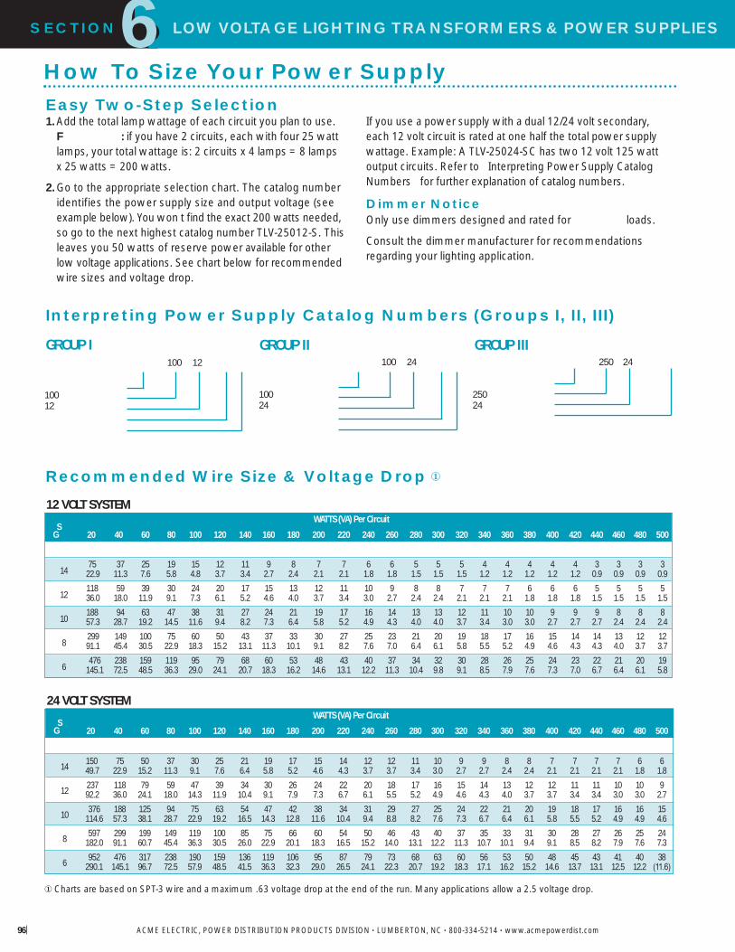
250 24
25024
6SECTION LOW VOLTAGE LIGHTING TRANSFORMERS&POWER SUPPLIES
ACME ELECTRIC, POWER DISTRIBUTION PRODUCTS DIVISION • LUMBERTON, NC • 800-334-5214 • www.acmepowerdist.com96
Easy Two-Step Selection1.Add the total lamp wattage of each circuit you plan to use.
F : if you have 2 circuits, each with four 25 watt lamps, your total wattage is: 2 circuits x 4 lamps = 8 lamps x 25 watts = 200 watts.
2.Go to the appropriate selection chart. The catalog numberidentifies the power supply size and output voltage (seeexample below). You won t find the exact 200 watts needed,so go to the next highest catalog number TLV-25012-S. Thisleaves you 50 watts of reserve power available for otherlow voltage applications. See chart below for recommendedwire sizes and voltage drop.
100 12
10012
How To Size Your Power Supply
If you use a power supply with a dual 12/24 volt secondary,each 12 volt circuit is rated at one half the total power supplywattage. Example: A TLV-25024-SC has two 12 volt 125 wattoutput circuits. Refer to Interpreting Power Supply CatalogNumbers for further explanation of catalog numbers.
Dimmer NoticeOnly use dimmers designed and rated for loads.
Consult the dimmer manufacturer for recommendationsregarding your lighting application.
Interpreting Power Supply Catalog Numbers (Groups I, II, III)
12 VOLT SYSTEM
24 VOLT SYSTEM
100 24
10024
GROUP I GROUP II GROUP III
Recommended Wire Size & Voltage Drop �
� Charts are based on SPT-3 wire and a maximum .63 voltage drop at the end of the run. Many applications allow a 2.5 voltage drop.
SG
14
12
10
8
6
SG
14
12
10
8
6
WATTS (VA) Per Circuit
20 40 60 80 100 120 140 160 180 200 220 240 260 280 300 320 340 360 380 400 420 440 460 480 500
150 75 50 37 30 25 21 19 17 15 14 12 12 11 10 9 9 8 8 7 7 7 7 6 649.7 22.9 15.2 11.3 9.1 7.6 6.4 5.8 5.2 4.6 4.3 3.7 3.7 3.4 3.0 2.7 2.7 2.4 2.4 2.1 2.1 2.1 2.1 1.8 1.8237 118 79 59 47 39 34 30 26 24 22 20 18 17 16 15 14 13 12 12 11 11 10 10 992.2 36.0 24.1 18.0 14.3 11.9 10.4 9.1 7.9 7.3 6.7 6.1 5.5 5.2 4.9 4.6 4.3 4.0 3.7 3.7 3.4 3.4 3.0 3.0 2.7376 188 125 94 75 63 54 47 42 38 34 31 29 27 25 24 22 21 20 19 18 17 16 16 15
114.6 57.3 38.1 28.7 22.9 19.2 16.5 14.3 12.8 11.6 10.4 9.4 8.8 8.2 7.6 7.3 6.7 6.4 6.1 5.8 5.5 5.2 4.9 4.9 4.6597 299 199 149 119 100 85 75 66 60 54 50 46 43 40 37 35 33 31 30 28 27 26 25 24
182.0 91.1 60.7 45.4 36.3 30.5 26.0 22.9 20.1 18.3 16.5 15.2 14.0 13.1 12.2 11.3 10.7 10.1 9.4 9.1 8.5 8.2 7.9 7.6 7.3952 476 317 238 190 159 136 119 106 95 87 79 73 68 63 60 56 53 50 48 45 43 41 40 38
290.1 145.1 96.7 72.5 57.9 48.5 41.5 36.3 32.3 29.0 26.5 24.1 22.3 20.7 19.2 18.3 17.1 16.2 15.2 14.6 13.7 13.1 12.5 12.2 (11.6)
WATTS (VA) Per Circuit
20 40 60 80 100 120 140 160 180 200 220 240 260 280 300 320 340 360 380 400 420 440 460 480 500
75 37 25 19 15 12 11 9 8 7 7 6 6 5 5 5 4 4 4 4 4 3 3 3 322.9 11.3 7.6 5.8 4.8 3.7 3.4 2.7 2.4 2.1 2.1 1.8 1.8 1.5 1.5 1.5 1.2 1.2 1.2 1.2 1.2 0.9 0.9 0.9 0.9118 59 39 30 24 20 17 15 13 12 11 10 9 8 8 7 7 7 6 6 6 5 5 5 536.0 18.0 11.9 9.1 7.3 6.1 5.2 4.6 4.0 3.7 3.4 3.0 2.7 2.4 2.4 2.1 2.1 2.1 1.8 1.8 1.8 1.5 1.5 1.5 1.5188 94 63 47 38 31 27 24 21 19 17 16 14 13 13 12 11 10 10 9 9 9 8 8 857.3 28.7 19.2 14.5 11.6 9.4 8.2 7.3 6.4 5.8 5.2 4.9 4.3 4.0 4.0 3.7 3.4 3.0 3.0 2.7 2.7 2.7 2.4 2.4 2.4299 149 100 75 60 50 43 37 33 30 27 25 23 21 20 19 18 17 16 15 14 14 13 12 1291.1 45.4 30.5 22.9 18.3 15.2 13.1 11.3 10.1 9.1 8.2 7.6 7.0 6.4 6.1 5.8 5.5 5.2 4.9 4.6 4.3 4.3 4.0 3.7 3.7476 238 159 119 95 79 68 60 53 48 43 40 37 34 32 30 28 26 25 24 23 22 21 20 19
145.1 72.5 48.5 36.3 29.0 24.1 20.7 18.3 16.2 14.6 13.1 12.2 11.3 10.4 9.8 9.1 8.5 7.9 7.6 7.3 7.0 6.7 6.4 6.1 5.8

6SECTION LOW VOLTAGE LIGHTING TRANSFORMERS&POWER SUPPLIES
ACME ELECTRIC, POWER DISTRIBUTION PRODUCTS DIVISION • LUMBERTON, NC • 800-334-5214 • www.acmepowerdist.com
Low Voltage Lighting Power Supplies with 24-Hour Timer &Photocell
FEATURES� 100, 150, 300, 600 Watt Models.� 120V Primary, 12V or 12/24 V
Secondary, 60 Hz.� Fully encapsulated core and coil.� 24-hour timer and photocell.� Wall mounting brackets included.� UL Listed.� Screw lug terminals for ease
of wiring.� Deadfront terminal cover for
added safety.
E - -RN
6 (1.8 ) P C G P
24
RF C
M B K S
Screw Lug Output Terminals
P
AS
RS
H
D
BOTTOMVIEW
.88 x 1.13 in.(2.2 x 2.9 cm.)
Knockout
120VPower Cord
W
1.38 in.(3.5 cm.)
� 12/24V denotes a three wire circuit, one 24V output or two 12V outputs. Each 12V is rated at one half the nameplate wattage.� Dimensions not suitable for construction purposes. Contact factory for certified drawings.
� 3-Position on-off-auto switch forversatility.
� Removable front cover, generous wiring space.
� 6 power cord with grounded plug.� Voltage regulation switch for 11, 12
or 13 volts.� Overload protection on primary and
secondary sides.� 10-year limited product warranty
(3-years on timer/photocell).� Faraday shielded for greater safety.
IRING DIAGRAMSH1
120VH2
X1 X212V
OR=X1
H1
X2
120V
12V
H2
12VX3 X1
H1120V
24V
H2
X3
12/24 V Units
12V Units
GROUP I
SELECTION G IDE
120V INPUT 120V INPUT APPRO DIMENSIONS � APPROATTS 12V OUTPUT 12 24V OUTPUT � INCHES CM SHIP EIGHT
CATALOG NO CATALOG NO HEIGHT IDTH DEPTH LBS KG
300 30012 30024 19.00 48.3 4.62 11.7 4.25 10.8 14 6.4
600 60012 60024 19.00 48.3 4.62 11.7 4.25 10.8 18 8.2

SECTION LOW VOLTAGE LIGHTING TRANSFORMERS&POWER SUPPLIES6
ACME ELECTRIC, POWER DISTRIBUTION PRODUCTS DIVISION • LUMBERTON, NC • 800-334-5214 • www.acmepowerdist.com98
� Push to reset Thermal Breaker.� Magnetic Breaker Toggle On/Off. Low voltage circuit breakers are for protection only and are not to be used as an on/off switch for 100 and 150 watt 12 volt units or on 100, 150
and 250 watt 12/24 volt units.� 12/24 volt output denotes a three-wire circuit, one 24 volt output or two 12 volt outputs. Each 12 volt output is rated at 1/2 nameplate wattage. Dimensions not for construction purposes. Contact factory for certified drawings.
WIRING DIAGRAMS
Power Supply Specifications, Dimensions & Selection
WITHOUT LOW VOLTAGE CIRCUIT BREAKERS
H1120V
H2
X1 X212V
OR=X1
H1
X2
120V
12V
H2
12VX3 X1
H1120V
24V
H2
X3
12/24 V Units
12V Units
ITH LO VOLTAGE CIRCUIT BREAKERS
GROUP II
GROUP III
SELECTION G IDE
WITHOUT LINE CORD WITH LINE CORD120 V I 120 V I 120 V I A12 V O 12 24 V O � 12 V O A D SUL 506 L UL 506 L UL 1012 L I CC N C N C N H D L K
100 10012 � 10024 � 10012 � 13.00 33.0 3.91 9.9 3.98 10.1 9 4.1150 15012 � 15024 � 15012 � 13.00 33.0 3.91 9.9 3.98 10.1 9 4.1250 25012 � 25024 � 25012 � 13.00 33.0 3.91 9.9 3.98 10.1 12 5.4500 50012 � 50024 � 50012 � 14.00 35.6 4.66 11.8 4.60 11.7 17 7.7750 75012 � 75024 � 14.00 35.6 4.66 11.8 4.60 11.7 20 9.1
1000 100012 � 100024 � 15.35 39.0 5.41 13.7 5.23 13.3 28 12.71500 150024 � 15.35 39.0 5.41 13.7 5.23 13.3 35 15.9
WITHOUT LINE CORD120 V I 120 V I A12 V O 12 24 V O � A D SUL 506 L UL 506 L I CC N C N H D L K
100 10012 10024 13.00 33.0 3.91 9.9 3.98 10.1 9 4.1150 15012 15024 13.00 33.0 3.91 9.9 3.98 10.1 9 4.1250 25012 25024 13.00 33.0 3.91 9.9 3.98 10.1 12 5.4500 50012 50024 14.00 35.6 4.66 11.8 4.60 11.7 17 7.7750 75012 75024 14.00 35.6 4.66 11.8 4.60 11.7 20 9.1
1000 100012 100024 15.35 39.0 5.41 13.7 5.23 13.3 28 12.71500 150024 15.35 39.0 5.41 13.7 5.23 13.3 35 15.9

Pool & Spa Specifications Dimensions & Selection
GUIDE CHART �
For Selecting Secondary Voltage Tap To Be Used With VariousWire Sizes For Given Distances Between Transformer And Lamps
� Suffix – SL denotes primary cable entry from left side, low voltage right side. Suffix – SR denotes primary cable entry from right side, low voltage left side.All units have auto-thermal reset.
� Confirm tap selection by measurement of voltage at lamp terminals when all of the lamps are operating.
SECTION LOW VOLTAGE LIGHTING TRANSFORMERS&POWER SUPPLIES6
ACME ELECTRIC, POWER DISTRIBUTION PRODUCTS DIVISION • LUMBERTON, NC • 800-334-5214 • www.acmepowerdist.com 99
14V13V12V
0V
120V
BLACK
WHITE
ENCLOSURE MUSTBE GROUNDED
MAXIMUM WINDING RISE 115° C100, 300 & 500 VA
120 VOLT INPUT — 12, 13 OR 14 VOLT OUTPUT — 1Ø, 60 Hz
WIRING DIAGRAMS
GROUP IV
COLD - ROLLED STAINLESS STEEL APPROX. DIMENSIONS APPROX. KNOCKOUT PRIMARY SECONDARYVA STEEL ENCLOSURE ENCLOSURE INCHES (CM.) SHIP. WEIGHT SIZE CURRENT LDS. LDS.
RATING CATALOG NO. � CATALOG NO. � HEIGHT WIDTH DEPTH LBS. (KG.) IN. (CM.) (MAX. AMPS) 2 PCS. OF # 4 PCS. OF #100 1 79101 79101 8.40 21.3 3.50 8.9 4.83 12.3 7 3.2100 1 79101 79101 8.40 21.3 3.50 8.9 4.83 12.3 7 3.2 .875 2.2 8.3 14 12
300 1 79203 79203 8.40 21.3 4.22 10.7 5.50 14.0 12 5.4300 1 79203 79203 8.40 21.3 4.22 10.7 5.50 14.0 12 5.4 .875 2.2 25.0 14 12
500 1 79105 79105 10.00 25.4 4.41 11.2 5.66 14.4 15 6.8500 1 79105 79105 10.00 25.4 4.41 11.2 5.66 14.4 15 6.8 .875 2.2 41.6 14 10
DISTANCE FT. (M.) FROM TRANSFORMER TO LAMPS FOR 100 WATT LOADS L T
G 30 9 1 30 9 1 60 18 3 90 27 4 120 36 6 150 45 7 180 54 9 210 64 0 240 73 2 270 82 3 300 91 4
14 12 13 14
12 12 13 13 14
10 12 13 13 14 14
8 12 12 12 13 13 13 14 14 14
DISTANCE FT. (M.) FROM TRANSFORMER TO LAMPS FOR 300 WATT LOAD
S L TG 10 3 0 10 3 0 20 6 1 30 9 1 40 12 2 50 15 2 60 18 3 70 21 3 80 24 4 90 27 4 100 30 5 110 33 5 120 36 6
12 12 13 13 14
10 12 12 13 13 14 14
8 12 12 12 13 13 13 14 14 14
6 12 12 12 12 13 13 13 13 14 14 14 14 14
DISTANCE FT. (M.) FROM TRANSFORMER TO LAMPS FOR 500 WATT LOAD
S L TG 10 3 0 10 3 0 20 6 1 30 9 1 40 12 2 50 15 2 60 18 3 70 21 3 80 24 4 90 27 4 100 30 5 110 33 5 120 36 6
10 12 13 14 14
8 12 12 13 13 14
6 12 12 13 13 13 14 14 14
4 12 12 12 12 13 13 13 13 14 14 14 14 14
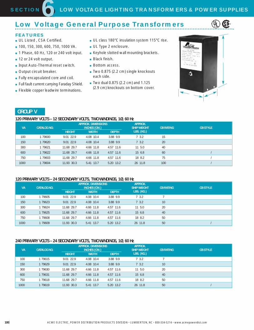
SECTION LOW VOLTAGE LIGHTING TRANSFORMERS&POWER SUPPLIES6
ACME ELECTRIC, POWER DISTRIBUTION PRODUCTS DIVISION • LUMBERTON, NC • 800-334-5214 • www.acmepowerdist.com100
Low Voltage General Purpose TransformersFEATURES� UL Listed , CSA Certified.� 100, 150, 300, 600, 750, 1000 VA.� 1 Phase, 60 Hz, 120 or 240 volt input.� 12 or 24 volt output.� Input Auto-Thermal reset switch.� Output circuit breaker.� Fully encapsulated core and coil.� Full fault current carrying Faraday Shield.� Flexible copper leadwire terminations.
� UL class 180°C insulation system 115°C rise.� UL Type 2 enclosure.� Keyhole slotted wall mounting brackets.� Black finish.� Bottom access.� Two 0.875 (2.2 cm) single knockouts
each side.� Two dual 0.875 (2.2 cm) and 1.125
(2.9 cm) knockouts on bottom cover.
120 PRIMARY VOLTS – 12 SECONDARY VOLTS, TWO WINDINGS, 1Ø, 60 Hz
120 PRIMARY VOLTS – 24 SECONDARY VOLTS, TWO WINDINGS, 1Ø, 60 Hz
240 PRIMARY VOLTS – 24 SECONDARY VOLTS, TWO WINDINGS, 1Ø, 60 Hz
GROUP V
APPROX. DIMENSIONS APPROX.VA CATALOG NO. INCHES (CM.) SHIP WEIGHT CB RATING CB STYLE
HEIGHT WIDTH DEPTH LBS. (KG.)
100 1 79600 9.01 22.9 4.08 10.4 3.88 9.9 7 3.2 15150 1 79620 9.01 22.9 4.08 10.4 3.88 9.9 7 3.2 20300 1 79621 11.68 29.7 4.66 11.8 4.57 11.6 11 5.0 40600 1 79622 11.68 29.7 4.66 11.8 4.57 11.6 15 6.8 60 /750 1 79603 11.68 29.7 4.66 11.8 4.57 11.6 18 8.2 75 /
1000 1 79604 11.93 30.3 5.41 13.7 5.20 13.2 26 11.8 100 /
APPROX. DIMENSIONS APPROX.VA CATALOG NO. INCHES (CM.) SHIP WEIGHT CB RATING CB STYLE
HEIGHT WIDTH DEPTH LBS. (KG.)
100 1 79605 9.01 22.9 4.08 10.4 3.88 9.9 7 3.2 7150 1 79623 9.01 22.9 4.08 10.4 3.88 9.9 7 3.2 10300 1 79624 11.68 29.7 4.66 11.8 4.57 11.6 11 5.0 20600 1 79625 11.68 29.7 4.66 11.8 4.57 11.6 15 6.8 40750 1 79608 11.68 29.7 4.66 11.8 4.57 11.6 18 8.2 50
1000 1 79609 11.93 30.3 5.41 13.7 5.20 13.2 26 11.8 50 /
APPROX. DIMENSIONS APPROX.VA CATALOG NO. INCHES (CM.) SHIP WEIGHT CB RATING CB STYLE
HEIGHT WIDTH DEPTH LBS. (KG.)
100 1 79615 9.01 22.9 4.08 10.4 3.88 9.9 7 3.2 7150 1 79629 9.01 22.9 4.08 10.4 3.88 9.9 7 3.2 10300 1 79630 11.68 29.7 4.66 11.8 4.57 11.6 11 5.0 20600 1 79631 11.68 29.7 4.66 11.8 4.57 11.6 15 6.8 40750 1 79618 11.68 29.7 4.66 11.8 4.57 11.6 18 8.2 50
1000 1 79619 11.93 30.3 5.41 13.7 5.20 13.2 26 11.8 50 /

Buck-Boost Transformers
The No-Frills LowVoltage LightingAlternativeBuck-Boost Transformers offer a no-frills approach to low voltage lighting.(See Chart Below) A typical Buck-Boost application is 120 volts in and12 volts out for low voltage lighting orcontrol circuitry. In most applications, thislow voltage isolation transformer isfield connected as an autotransformer.For more information on Buck-BoostTransformers, refer to the next sectionin this catalog.
SECTION LOW VOLTAGE LIGHTING TRANSFORMERS&POWER SUPPLIES6
ACME ELECTRIC, POWER DISTRIBUTION PRODUCTS DIVISION • LUMBERTON, NC • 800-334-5214 • www.acmepowerdist.com
120 x 240 VOLT INPUT– 12/24 VOLT OUTPUT – 1Ø, 60 Hz
GROUP VI
INSULATING SECONDAR MA IMUM APPRO DIMENSIONS APPROCATALOG TRANSFORMER CURRENT OUTPUT INCHES CM NET EIGHTNUMBER RATING 12V 24V HEIGHT IDTH DEPTH LBS KG
1 81047 0.05 4.16 2.08 6.38 16.2 3.19 8.1 3.00 7.6 4 1.8
1 81048 0.10 8.32 4.16 6.62 16.8 3.75 9.5 3.62 9.2 5 2.3
1 81049 0.15 12.52 6.25 7.12 18.1 3.75 9.5 3.62 9.2 7 3.2
1 81050 0.25 20.80 10.40 8.68 22.0 4.08 10.4 3.88 9.9 10 4.5
1 81051 0.50 41.60 20.80 9.06 23.0 4.37 11.1 4.20 10.7 15 6.8
1 81052 0.75 62.50 31.25 9.68 24.6 4.75 12.1 4.51 11.5 19 8.6
1 11683 1.00 83.20 41.60 10.50 26.7 5.50 14.0 5.13 13.0 24 10.9
1 11684 1.50 125.00 62.50 11.62 29.5 5.50 14.0 5.13 13.0 30 13.6
1 11685 2.00 166.00 83.20 13.00 33.0 5.50 14.0 5.13 13.0 38 17.2
1 11686 3.00 250.00 125.00 11.50 29.2 10.31 26.2 7.13 18.1 55 24.9
1 11687 5.00 416.00 208.00 14.38 36.5 10.31 26.2 7.13 18.1 75 34.0
2 11688 7.50 625.00 312.50 21.19 53.8 13.50 34.3 10.84 27.5 125 56.7
2 11689 10.00 833.00 416.60 21.19 53.8 13.50 34.3 10.84 27.5 160 72.6

VOLTAGE DROP FORMULA
X
=
SECTION LOW VOLTAGE LIGHTING TRANSFORMERS&POWER SUPPLIES6
ACME ELECTRIC, POWER DISTRIBUTION PRODUCTS DIVISION • LUMBERTON, NC • 800-334-5214 • www.acmepowerdist.com102
12/2 Wire300W
POWER SUPPLY
12/2 Wire
50w
50w
50w
50w
50w50w
80'(24.4 m)
100'(30.5 m)
50'(15.2 m)
A typical installation showingthree separate runs on a 300WPower Supply
GROUP VI
Low Voltage Lighting Wiring Diagrams
X1
H1
X2
120V
12V
H2
X1
H1
X2
120V
24V
H2
X1
H1
X2
240V
12V
H2
X1
H1
X2
240V
24V
H2
X1 X2 X3 X4
120VINPUT
H4H1
H3H2
12VOUTPUT
X1 X2 X3 X4
240VINPUT
12VOUTPUT
H1H2H3H4
X1 X2 X3 X4
120VINPUT
H4H1
H3H2
24VOUTPUT
X1 X2 X3 X4
240VINPUT
24VOUTPUT
H1H2H3H4
GROUP V
VOLTAGE DROP CHARTVoltage Life Expectancy % of Ratedat Lamp of Lamp Candlepower
13.2 2/3 350
12.6 3/4 180
12.0 100
11.5 2 80
11.0 3 74
10.5 5 6510.0 9 50
CABLE SIZE CONSTANT CHARTCable Cable SizeSize Constant
18 1380
16 2200
14 3500
12 7500
10 11 920
8 18 960
6 30 150

SECTION
6
Description & Applications . . . . . . . . . . . . . . . .104
Questions & Answers . . . . . . . . . . . . . . . .105-109
Selection Charts – Single Phase . . . . . . . .110-112
Selection Charts – Three Phase . . . . . . . .113-115
Specifications . . . . . . . . . . . . . . . . . . . . . . . . . .116
Wiring Diagrams . . . . . . . . . . . . . . . . . . . .117-118
B CK-BOOSTTRANSFORMERS
7

Why Use Buck-Boost Insteadof Another Type Transformer ?Take a look at the advantages and disadvantages of usinga buck-boost transformer (autotransformer) comparedto a standard isolation transformer of the proper size andvoltage combination.
As you can see, the advantages are many, the economiesgreat. Buck-boost transformers are readily availablefrom the stock of your nearest Power DistributionProducts Distributor.
SECTION BUCK-BOOST TRANSFORMERS7
ACME ELECTRIC, POWER DISTRIBUTION PRODUCTS DIVISION • LUMBERTON, NC • 800-334-5214 • www.acmepowerdist.com104
A typical buck-boost application is 120 volts in, 12 voltsout for low voltage lighting or control circuitry. In mostapplications, this low voltage transformer is field connectedas an autotransformer. (See question 2 for the definitionof an autotransformer). Buck-boost transformers providetremendous capabilities and flexibility in KVA sizes andinput/output voltage combinations. B 75
... .
Other buck-boost applications are, where (A) low supplyvoltage exists because equipment is installed at the endof a bus system; (B) the supply system is operating at orover its design capacity; and (C) where overall consumerdemands may be so high the utility cuts back the supplyvoltage to the consumer causing a brownout.
Where Are Buck-BoostTransformers Used?
T-2-11688 T-1-11683
Proper Voltage Is CriticalWith nearly two-thirds of all electrical loads being A.C. motorloads, maintenance of the proper voltage to that motor is veryimportant. If the supply line voltage is not maintained, motorwinding current is increased causing reduced motor torque andescalating motor temperature, all of which results in the rapidloss of insulation life expectancy.
In addition to motor loads, the detrimental effects of low voltageon both resistive heating loads and incandescent lighting outputis illustrated in the chart.
A , .
Buck-boost transformers are an economical way to correct thispotentially very serious problem. A a line voltage changein the 5-20% range is required, a buck-boost transformer shouldbe considered as your first line of defense.
ADVANTAGESMore efficientSmaller & lighter5-10 times increase in KVAVersatile, many applications
Lower cost
DISADVANTAGESNo circuit isolationCannot create aneutralApplication voltages andKVA don t match the nameplate voltages and KVA

SECTION BUCK-BOOST TRANSFORMERS7
ACME ELECTRIC, POWER DISTRIBUTION PRODUCTS DIVISION • LUMBERTON, NC • 800-334-5214 • www.acmepowerdist.com
1.What is a buck-boost transformer?Buck-boost transformers are small single phase transformersdesigned to reduce (buck) or raise (boost) line voltage from 5 -20%. The most common example is boosting 208 volts to230 volts, usually to operate a 230 volt motor such as an air-conditioner compressor, from a 208 volt supply line.
Buck-boosts are a standard type of single phase distributiontransformers, with primary voltages of 120, 240 or 480 voltsand secondaries typically of 12, 16, 24, 32 or 48 volts. Theyare available in sizes ranging from 50 volt amperes to 10kilo-volt amperes.
Buck-boost transformers are shipped ready to be connectedfor a number of possible voltage combinations.
X1
X2
X3
X4
OUTPUT
H4
INPUTH2
H3
H1
X1
X2
X3
X4
OUTPUT
H4
INPUTH2
H3
H1 X1
X2
X3
X4
OUTPUT
H4
INPUT H2
H3
H1
Questions & Answers About Buck-Boost Transformers
How Low Voltage Affects VariousEquipment Operations and Functions
150
140
130
120
110
100
90
80
70
60
50
901/2
81
72
105
111
117
84
70
57
111
123
138
901/2
81
72
5
10
15
F 1 B F 2 ST
H1 4
F 3 I N 2
2. How does a buck-boost transformer differ from an insulating transformer?A buck-boost transformer IS an insulating type transformer whenit is shipped from the factory. When it is connected at the jobsite, a lead wire on the primary is connected to a lead wire onthe secondary – thereby changing the transformer s electricalcharacteristics to those of an autotransformer. The primary andsecondary windings are no longer insulated and secondarywindings are no longer insulated and its KVA capacity isgreatly increased. Refer to figures 1, 2 and 3.
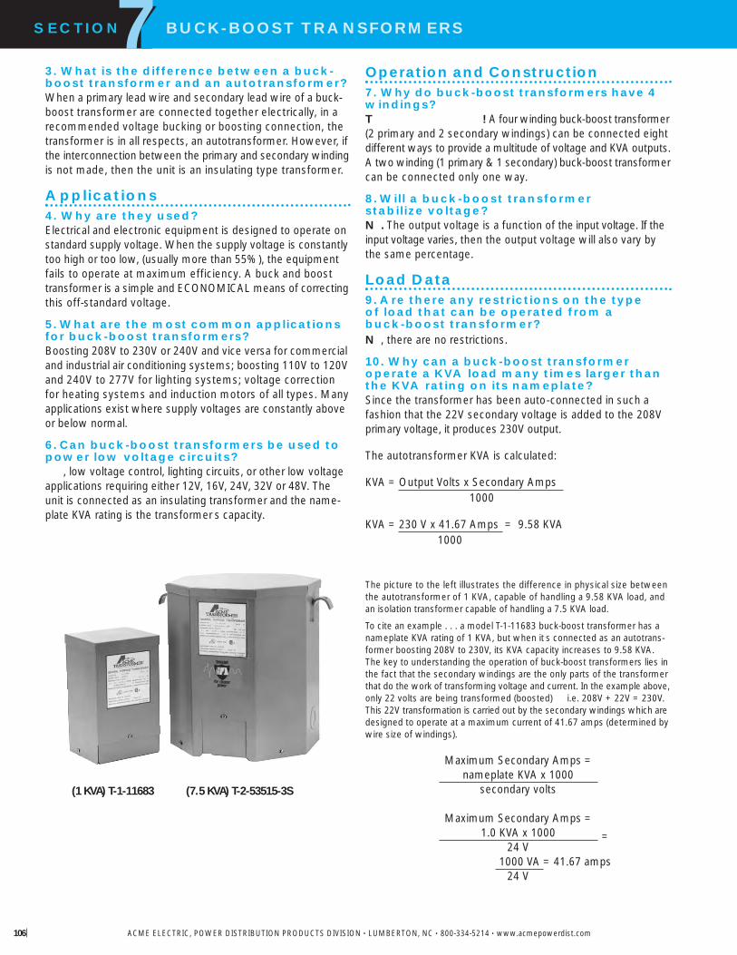
SECTION BUCK-BOOST TRANSFORMERS7
ACME ELECTRIC, POWER DISTRIBUTION PRODUCTS DIVISION • LUMBERTON, NC • 800-334-5214 • www.acmepowerdist.com106
Operation and Construction7. Why do buck-boost transformers have 4windings?T ! A four winding buck-boost transformer(2 primary and 2 secondary windings) can be connected eightdifferent ways to provide a multitude of voltage and KVA outputs.A two winding (1 primary & 1 secondary) buck-boost transformercan be connected only one way.
8.Will a buck-boost transformer stabilize voltage?N . The output voltage is a function of the input voltage. If theinput voltage varies, then the output voltage will also vary bythe same percentage.
Load Data9.Are there any restrictions on the type of load that can be operated from a buck-boost transformer?N , there are no restrictions.
10. Why can a buck-boost transformer operate a KVA load many times larger thanthe KVA rating on its nameplate?Since the transformer has been auto-connected in such afashion that the 22V secondary voltage is added to the 208Vprimary voltage, it produces 230V output.
The autotransformer KVA is calculated:
KVA = Output Volts x Secondary Amps1000
KVA = 230 V x 41.67 Amps = 9.58 KVA1000
3. What is the difference between a buck-boost transformer and an autotransformer?When a primary lead wire and secondary lead wire of a buck-boost transformer are connected together electrically, in arecommended voltage bucking or boosting connection, thetransformer is in all respects, an autotransformer. However, ifthe interconnection between the primary and secondary windingis not made, then the unit is an insulating type transformer.
Applications4. Why are they used?Electrical and electronic equipment is designed to operate onstandard supply voltage. When the supply voltage is constantlytoo high or too low, (usually more than 55%), the equipmentfails to operate at maximum efficiency. A buck and boosttransformer is a simple and ECONOMICAL means of correctingthis off-standard voltage.
5.What are the most common applicationsfor buck-boost transformers?Boosting 208V to 230V or 240V and vice versa for commercialand industrial air conditioning systems; boosting 110V to 120Vand 240V to 277V for lighting systems; voltage correctionfor heating systems and induction motors of all types. Manyapplications exist where supply voltages are constantly aboveor below normal.
6.Can buck-boost transformers be used topower low voltage circuits?
, low voltage control, lighting circuits, or other low voltageapplications requiring either 12V, 16V, 24V, 32V or 48V. Theunit is connected as an insulating transformer and the name-plate KVA rating is the transformer s capacity.
The picture to the left illustrates the difference in physical size betweenthe autotransformer of 1 KVA, capable of handling a 9.58 KVA load, andan isolation transformer capable of handling a 7.5 KVA load.
To cite an example . . . a model T-1-11683 buck-boost transformer has anameplate KVA rating of 1 KVA, but when it s connected as an autotrans-former boosting 208V to 230V, its KVA capacity increases to 9.58 KVA.The key to understanding the operation of buck-boost transformers lies inthe fact that the secondary windings are the only parts of the transformerthat do the work of transforming voltage and current. In the example above,only 22 volts are being transformed (boosted) i.e. 208V + 22V = 230V.This 22V transformation is carried out by the secondary windings which aredesigned to operate at a maximum current of 41.67 amps (determined bywire size of windings).
Maximum Secondary Amps =nameplate KVA x 1000
secondary volts
Maximum Secondary Amps =1.0 KVA x 1000
24 V1000 VA = 41.67 amps
24 V
(1 KVA) T-1-11683 (7.5 KVA) T-2-53515-3S
=
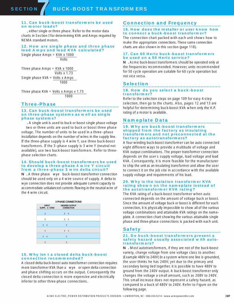
3 PHASE CONNECTIONS
11. Can buck-boost transformers be usedon motor loads?
, either single or three phase. Refer to the motor datacharts in Section I for determining KVA and Amps required byNEMA standard motors.
12. How are single phase and three phaseload Amps and load KVA calculated?Single phase Amps = KVA x 1000
Volts
Three phase Amps = KVA x 1000Volts x 1.73
Single phase KVA = Volts x Amps1000
Three phase KVA = Volts x Amps x 1.731000
Three-Phase13. Can buck-boost transformers be usedon three-phase systems as well as singlephase systems?
. A single unit is used to buck or boost single phase voltage two or three units are used to buck or boost three phase
voltage. The number of units to be used in a three -phaseinstallation depends on the number of wires in the supply line.If the three-phase supply is 4 wire Y, use three buck-boosttransformers. If the 3-phase supply is 3 wire Y (neutral notavailable), use two buck-boost transformers. Refer to three-phase selection charts.
14. Should buck-boost transformers be usedto develop a three-phase 4 wire Y circuitfrom a three-phase 3 wire delta circuit?N . A three phase wye buck-boost transformer connectionshould be used only on a 4 wire source of supply. A delta towye connection does not provide adequate current capacity toaccommodate unbalanced currents flowing in the neutral wire ofthe 4 wire circuit.
15. Why isn t a closed delta buck-boostconnection recommended?A closed delta buck-boost auto transformer connection requiresmore transformer KVA than a wye or open delta connectionand phase shifting occurs on the output. Consequently theclosed delta connection is more expensive and electricallyinferior to other three-phase connections.
Connection and Frequency16. How does the installer or user know howto connect a buck-boost transformer?The connection chart packed with each unit shows how tomake the appropriate connections. These same connectioncharts are also shown in this section (page 118).
17. Can 60 Hertz buck-boost transformersbe used on a 50 Hertz service?N . Acme buck-boost transformers should be operated only atthe frequencies recommended. However, units recommendedfor 50 cycle operation are suitable for 60 cycle operation butnot vice versa.
Selection18. How do you select a buck-boosttransformer?Refer to the selection steps on page 109 for easy 4-stepselection, then go to the charts. Also, pages 12 and 13 arehelpful for determining buck-boost KVA when only the H.P.rating of a motor is available.
Nameplate Data19. Why are buck-boost transformers shipped from the factory as insulating transformers and not preconnected at thefactory as autotransformers?A four winding buck-boost transformer can be auto connectedeight different ways to provide a multitude of voltage andKVA output combinations. The proper transformer connectiondepends on the user s supply voltage, load voltage and loadKVA. Consequently, it is more feasible for the manufacturerto ship the unit as an insulating transformer and allow the userto connect it on the job site in accordance with the availablesupply voltage and requirements of his load.
20. Why is the isolation transformer KVArating shown on the nameplate instead ofthe autotransformer KVA rating?The KVA rating of a buck-boost transformer when autoconnected depends on the amount of voltage buck or boost.Since the amount of voltage buck or boost is different for eachconnection, it is physically impossible to show all of the variousvoltage combinations and attainable KVA ratings on the name-plate. A connection chart showing the various attainable singlephase and three-phase connections is packed with each unit.
Safety21. Do buck-boost transformers present asafety hazard usually associated with auto-transformers?N . Most autotransformers, if they are not of the buck-boostvariety, change voltage from one voltage class to another.(Example 480V to 240V) In a system where one line is grounded,the user thinks he has 240V; yet due to the primary andsecondary being tied together, it is possible to have 480V toground from the 240V output. A buck-boost transformer onlychanges the voltage a small amount, such as 208V to 240V.This small increase does not represent a safety hazard, ascompared to a buck of 480V to 240V. Refer to Figure on thefollowing page.
SECTION BUCK-BOOST TRANSFORMERS7
ACME ELECTRIC, POWER DISTRIBUTION PRODUCTS DIVISION • LUMBERTON, NC • 800-334-5214 • www.acmepowerdist.com 107
INPUTSUPPL S STEM
3
3
3 4
4
3 4
3
DESIRED OUTPUTCONNECTION
3 4
3 4
3
3 4
3
3

Sound Levels22. Are buck-boost transformers as quiet asstandard isolation transformers?
. However, an auto-connected buck-boost transformerwill be quieter than an isolation transformer capable of handlingthe same load. The isolation transformer would have to bephysically larger than the buck-boost transformer, and smalltransformers are quieter than larger ones. (Example) 1 KVA 40 db; 75 KVA 50 db. (db is a unit of sound measure).
Cost and Life Expectancy23. How does the cost of a buck-boosttransformer compare to that of an insulatingtransformer both capable of handling thesame load?For the most common buck-boost applications, the dollarsavings are generally greater than 75% compared to theuse of an insulating type distribution transformer for thesame application.
24. What is the life expectancy of a buckboost transformer?The life expectancy of a buck-boost transformer is the same asthe life expectancy of other dry type transformers.
National Electrical Code25. Your catalog indicates that a buck-boosttransformer is suitable for connecting as anAUTOTRANS-FORMER. What is the definitionof an autotransformer and how does it differfrom an isolation transformer?An autotransformer is a transformer in which the primary (input)and the secondary (output) are electrically connected to eachother. An isolation transformer, also known as an insulatingtransformer, has complete electrical separation between theprimary (input) and the secondary (output). This is illustrated inthe drawing below
An autotransformer changes or transforms only a portion of theelectrical energy it transmits. The rest of the electrical energyflows directly through the electrical connections between theprimary and secondary. An isolation transformer (insulatingtransformer) changes or transforms all of the electrical energy it transmits.
Consequently, an autotransformer is smaller, lighter in weight,and less costly than a comparable KVA size insulating transformer.
Please refer to Question 27 for additional information onautotransformers.
Buck-boost transformers are frequently field-connected asautotransformers.
26. Buck-boost transformers are almostalways installed as auto-transformers. Doesthe N.E.C. (National Electrical Code) permit the use of autotransformers?
. Please refer to N.E.C. Article 450-4, Autotransformers600 Volts, Nominal, or Less. Item ( ) explains how to over-current protect an autotransformer; item ( ) explains that aninsulating transformer such as a buck-boost transformer maybe field connected as an autotransformer.
27. When a buck-boost transformer isconnected as an autotransformer such asboosting 208V to 230V, the KVA is greatlyincreased. What is the procedure for deter-mining the size (ampere rating) of the over-current protective device such as a fuse orcircuit breaker?The National Electrical Code Article 450-4 addresses over-current protection of autotransformers. A copy is reproducedbelow for easy reference.
450-4. A 600 , N , L .
( ) O P . Each autotransformer 600 volts,nominal, or less shall be protected by an individual overcurrentdevice installed in series with each ungrounded input conductor.Such overcurrent device shall be rated or set at not morethan 125 percent of the rated full-load input current of theautotransformer. An overcurrent device shall not be installedin series with the shunt winding (the winding common to boththe input and the output circuits) of the autotransformerbetween Points A and B as shown in Diagram 450-4.
400 VOLTSLINE TO GROUND(POTENTIAL SAFETY
HAZARD)
480VINPUT
240V OUTPUTLINE TO LINE
PRIMARY(INPUT)
PRIMARY(INPUT)
SECONDARY(OUTPUT)SECONDARY
(OUTPUT)
AUTOTRANSFORMER
ISOLATIONTRANSFORMER
(ALSO CALLED“INSULATING TRANSFORMER”)
SECTION BUCK-BOOST TRANSFORMERS7
ACME ELECTRIC, POWER DISTRIBUTION PRODUCTS DIVISION • LUMBERTON, NC • 800-334-5214 • www.acmepowerdist.com
SHUNT WINDING(S)
B
A
D 450 4

SECTION BUCK-BOOST TRANSFORMERS7
ACME ELECTRIC, POWER DISTRIBUTION PRODUCTS DIVISION • LUMBERTON, NC • 800-334-5214 • www.acmepowerdist.com 109
E : Where the rated input current of an autotrans-former is 9 amperes or more and 125 percent of this current doesnot correspond to a standard rating of a fuse or non-adjustablecircuit breaker, the next higher standard rating described inSection 240-6 shall be permitted. When the rated input currentis less than 9 amperes, an overcurrent device rated or set at notmore than 167 percent of the input current shall be permitted.
( ) T F -C A .A transformer field-connected as an autotransformer shall beidentified for use at elevated voltage.
28. I have noted the reprint of the N.E.C. (National Electrical Code), Article 450-4shown in the previous question coveringautotransformer overcurrent protection.Could you explain this article in detail byciting an example?An example of an everyday application is always a good wayto explain the intent of the Code. E : A 1 KVA trans-former Catalog No. T-1-11683 has a primary of 120 x 240V and asecondary of12x24V. It is to be connected as an autotransformerat the time of installation to raise 208V to 230V single phase.
When this 1 KVA unit is connected as an autotransformer forthis voltage combination, its KVA rating is increased to 9.58 KVA(may also be expressed as 9,580 VA). This is the rating to beused for determining the full load input amps and the sizing ofthe overcurrent protect device (fuse or breaker) on the input.
Full Load Input Amps =
9,580 Volt Amps = 46 Amps208 Volts
When the full load current is greater than 9 amps, the over-current protective device (usually a fuse or non-adjustablebreaker) amp rating can be up to 125 percent of the full loadrating of the autotransformer input amps.
Max. amp rating of theovercurrent device
= 46 amps x 125% = 57.5 amps
The National Electrical Code, Article 450-4 (a) Exception, permitsthe use of the next higher standard ampere rating of the over-current device. This is shown in Article 240-6 of the N.E.C.
Max. size of the fuse or circuit breaker= 60 amps
- .
L The voltage that you want to buck (decrease)or boost (increase). This can be found by measuring the supplyline voltage with a voltmeter.
L The voltage at which your equipment isdesigned to operate. This is listed on the nameplate of theload equipment.
L K A L A You do not need to know both one or the other is sufficient for selection purposes. Thisinformation usually can be found on the nameplate of theequipment that you want to operate.
F The supply line frequency must be the same asthe frequency of the equipment to be operated either 50 or60 cycles.
P The supply line should be the same as the equipmentto be operated either single or three phase.
Steps for Selecting the Proper Buck-Boost TransformerFour Step Selection1. A series of LINE VOLTAGE and LOAD VOLTAGE combinationsare listed across the top of each selection chart. Select a LINEVOLTAGE and LOAD VOLTAGE combination from ANY of thecharts that comes closest to matching the LINE VOLTAGE andLOAD VOLTAGE of your application.
2. Read down the column you have selected until you reacheither the LOAD KVA or LOAD AMPS of the equipment youwant to operate. You probably will not find the exact value ofLOAD KVA or LOAD AMPS so go to the next higher rating.
3. From this point, read across the column to the far left-handside and you have found the catalog number of the exactbuck-boost transformer you need. Refer to the catalog numberlisting on page 116 for dimensions.
4. CONNECT the transformer according to the connection diagramspecified at the bottom of the column where you selected YOURLINE VOLTAGE and LOAD VOLTAGE combination. Connectiondiagrams are found at the end of this section.
This same connection information is packed with each buck-boost transformer.

SECTION BUCK-BOOST TRANSFORMERS7
ACME ELECTRIC, POWER DISTRIBUTION PRODUCTS DIVISION • LUMBERTON, NC • 800-334-5214 • www.acmepowerdist.com
� 117 .NOTE: . 50/60 .
60 .117.
GROUP I
SELECTION CHARTS SINGLE PHASE
SINGLE PHASE BOOSTINGLine Voltage 95 100 105 110 189 208 215 220(Available)Load Voltage 114 120 115 120 208 230 237 242(Output)
CAT. NO.
Load KVA 0.24 0.25 0.48 0.50 0.43 0.48 0.49 0.50
T-1-81047 Amps 2.08 2.08 4.17 4.17 2.08 2.08 2.08 2.08Max. Size of 6 6 10 10 6 6 6 6Fuse or Breaker
Load KVA 0.47 0.50 0.96 1.01 0.87 0.96 0.99 1.01
T-1-81048 Amps 4.17 4.17 8.33 8.33 4.17 4.17 4.17 4.17Max. Size of 10 10 15 15 10 10 10 10Fuse or Breaker
Load KVA 0.71 0.75 1.43 1.51 1.30 1.43 1.48 1.51
T-1-81049 Amps 6.25 6.25 12.50 12.50 6.25 6.25 6.25 6.25Max. Size of 15 15 20 20 15 15 15 15Fuse or Breaker
Load KVA 1.19 1.25 2.40 2.50 2.16 2.39 2.46 2.52
T-1-81050 Amps 10.42 10.40 20.80 20.80 10.40 10.40 10.40 10.40Max. Size of 25 25 40 30 15 15 15 15Fuse or Breaker
Load KVA 2.37 2.50 4.80 5.00 4.33 4.79 4.93 5.04
T-1-81051 Amps 20.83 20.83 41.67 41.67 20.83 20.83 20.83 20.83Max. Size of 35 35 60 60 30 30 30 30Fuse or Breaker
Load KVA 3.56 3.75 7.17 7.56 6.50 7.19 7.41 7.56
T-1-81052 Amps 31.25 31.25 62.50 62.50 31.25 31.25 31.25 31.25Max. Size of 50 50 90 90 45 45 45 45Fuse or Breaker
Load KVA 4.75 5.00 9.58 10.00 8.66 9.58 9.87 10.00
T-1-11683 Amps 41.67 41.67 83.31 83.31 41.67 41.67 41.67 41.67Max. Size of 70 70 125 125 60 60 60 60Fuse or Breaker
Load KVA 7.12 7.50 14.40 15.10 13.00 14.30 14.80 15.10
T-1-11684 Amps 62.50 62.50 125.00 125.00 62.50 62.50 62.50 62.50Max. Size of 100 100 175 175 90 90 90 90Fuse or Breaker
Load KVA 9.50 10.00 19.20 20.20 17.30 19.16 19.70 20.10
T-1-11685 Amps 83.30 83.30 166.60 166.60 83.30 83.30 83.30 83.30Max. Size of 125 125 250 250 125 125 125 125Fuse or Breaker
Load KVA 14.20 15.00 28.80 30.00 26.00 28.70 29.60 30.30
T-1-11686 Amps 125.00 125.00 250.00 250.00 125.00 125.00 125.00 125.00Max. Size of 200 200 350 350 175 175 175 175Fuse or Breaker
Load KVA 23.70 25.00 47.90 50.00 43.30 47.80 49.30 50.30
T-1-11687 Amps 208.00 208.00 416.60 416.60 208.00 208.00 208.00 208.00Max. Size of 350 350 600 600 300 300 300 300Fuse or Breaker
Load KVA 35.60 37.50 71.90 75.60 65.00 71.80 74.00 75.60
T-2-11688 � Amps 312.50 312.50 625.00 625.00 312.50 312.50 312.50 312.50Max. Size of 500 500 1000 1000 450 450 450 450Fuse or Breaker
Load KVA 47.50 50.00 95.80 100.00 86.60 95.80 98.70 101.00
T-2-11689 � Amps 416.60 416.60 833.30 833.30 416.60 416.60 416.60 416.60Max. Size of 700 700 1200 1200 600 600 600 600Fuse or Breaker
See Page 118 For Connection Diagrams D D C C H H H H
BUCKING125 132 230 245 250 252
113 120 208 222 227 240
0.52 0.54 0.47 0.50 0.52 1.024.60 4.60 2.28 2.28 2.28 4.37
10 10 6 6 6 10
1.04 1.08 0.95 1.00 1.04 2.049.20 9.20 4.56 4.56 4.58 8.75
15 15 10 10 10 15
1.56 1.62 1.42 1.50 1.56 3.0013.80 13.80 6.86 6.86 6.86 13.10
20 20 15 15 15 15
2.60 2.75 2.37 2.50 2.60 5.1022.80 22.80 11.40 11.40 11.40 21.80
30 30 15 15 15 30
5.20 5.40 4.47 5.00 5.20 10.2046.80 46.80 22.80 22.80 22.80 43.70
60 60 30 30 30 60
7.80 8.15 7.10 7.50 7.80 15.3068.50 69.50 34.40 34.40 34.40 65.50
80 80 40 40 40 80
10.40 10.80 9.50 10.00 10.00 20.4091.50 91.50 45.80 45.80 45.80 87.50
110 110 60 60 50 110
15.00 16.20 14.24 15.00 15.60 30.60138.00 138.00 68.60 68.60 68.60 132.00
150 175 80 80 80 175
20.80 21.60 19.00 20.00 20.30 40.80183.00 183.00 91.60 91.60 91.20 175.00
225 225 110 110 110 225
31.20 32.50 28.50 30.00 31.20 61.00275.00 275.00 136.80 136.80 136.80 263.00
350 350 175 175 175 350
52.00 54.00 47.40 50.00 52.00 102.00457.00 457.00 228.00 228.00 228.00 437.00
600 600 300 300 300 600
78.00 81.00 71.00 76.00 78.00 153.00688.00 688.00 344.00 344.00 344.00 655.00
800 800 400 400 400 800
104.00 108.00 95.00 100.00 104.00 204.00915.00 915.00 458.00 458.00 458.00 875.00
1200 1200 600 600 600 1200
F F I I I E

SECTION BUCK-BOOST TRANSFORMERS7
ACME ELECTRIC, POWER DISTRIBUTION PRODUCTS DIVISION • LUMBERTON, NC • 800-334-5214 • www.acmepowerdist.com 111
� 117.
NOTE: I O ; KVA A 50 60 H A60 H
KVA 117
GROUP IISINGLE PHASE BOOSTING
L V 95 100 105 208 215 215 220 225AL V 120 114 119 240 244 230 235 240O
CAT NO
L KVA 0.19 0.36 0.37 0.38 0.38 0.72 0.73 0.75
T 1 81054 A 1.56 3.13 3.13 1.56 1.56 3.13 3.13 3.13M S 6 6 6 6 6 6 6 6F B
L KVA 0.38 0.71 0.74 0.75 0.76 1.44 1.47 1.50
T 1 81055 A 3.13 6.25 6.25 3.13 3.13 6.25 6.25 6.25M S 10 15 6 6 15 15 15 15F B
L KVA 0.56 1.07 1.12 1.13 1.14 2.16 2.20 2.25
T 1 81056 A 4.69 9.38 9.38 4.69 4.69 9.38 9.38 9.38M S 10 15 15 10 10 15 15 15F B
L KVA 0.94 1.78 1.86 1.88 1.91 3.59 3.67 3.75
T 1 81057 A 7.81 15.63 15.63 7.81 7.81 15.63 15.63 15.63M S 15 25 25 15 15 25 25 25F B
L KVA 1.88 3.56 3.72 3.75 3.81 7.19 7.34 7.50
T 1 81058 A 15.63 31.25 31.25 15.63 15.63 31.25 31.25 31.25M S 25 45 45 25 25 45 45 45F B
L KVA 2.81 5.34 5.58 5.63 5.72 10.78 11.02 11.25
T 1 81059 A 23.44 46.88 46.88 23.44 23.44 46.88 46.88 46.88M S 40 70 70 40 40 70 70 70F B
L KVA 3.75 7.13 7.44 7.50 7.63 14.38 14.69 15.00
T 1 13073 A 31.25 62.50 62.50 31.25 31.25 62.50 62.50 62.50M S 50 90 90 50 50 90 90 90F B
L KVA 5.63 10.69 11.16 11.25 11.44 21.56 22.03 22.50
T 1 13074 A 46.90 93.80 93.80 46.90 46.90 93.80 93.80 93.80M S 80 150 150 70 70 125 125 125F B
L KVA 7.50 14.25 14.88 15.00 15.25 28.75 29.38 30.00
T 1 13075 A 62.50 125.00 125.00 62.50 62.50 125.00 125.00 125.00M S 100 200 200 90 90 175 175 175F B
L KVA 11.25 21.38 22.31 22.50 22.88 43.13 44.06 45.00
T 1 13076 A 93.80 187.50 187.50 93.80 93.80 187.50 187.50 187.50M S 150 300 300 150 150 250 250 250F B
L KVA 18.75 35.63 37.19 37.50 38.13 71.88 73.44 75.00
T 1 13077 A 156.30 312.50 312.50 156.30 156.30 312.50 312.50 312.50M S 250 450 450 225 225 450 450 450F B
L KVA 28.10 53.40 55.80 56.30 57.20 107.80 110.20 112.50
T 2 13078 � A 234.40 468.80 468.80 234.40 234.40 468.80 468.80 468.80M S 400 700 700 350 350 700 700 700F B
L KVA 37.50 71.30 74.40 75.00 76.30 143.80 146.90 150.00
T 2 13079 � A 312.50 625.00 625.00 312.50 312.50 625.00 625.00 625.00M S 500 1000 1000 450 450 1000 1000 1000F B
S P 118 F D C C H H G G GC D
BUCKING
135 240 240 245 250 255
119 208 225 230 234 239
0.42 0.37 0.75 0.77 0.78 0.803.54 1.77 3.33 3.33 3.33 3.33
6 3 6 6 6 6
0.84 0.74 1.50 1.53 1.56 1.597.08 3.54 6.67 6.67 6.67 6.67
15 6 15 15 15 15
1.26 1.11 2.25 2.30 2.34 2.3910.63 5.31 10.00 10.00 10.00 10.00
15 6 15 15 15 15
2.11 1.84 3.75 3.83 3.90 3.9817.71 8.85 16.67 16.67 16.67 16.67
20 15 20 20 20 20
4.21 3.68 7.50 7.67 7.80 7.9735.42 17.71 33.33 33.33 33.33 33.33
40 20 40 40 40 40
6.32 5.53 11.25 11.50 11.70 11.9553.13 26.56 50.00 50.00 50.00 50.00
60 30 60 60 60 60
8.43 7.37 15.00 15.33 15.60 15.9370.83 35.42 66.67 66.67 66.67 66.67
80 40 80 80 80 80
12.64 11.05 22.50 23.00 23.40 23.90106.30 53.10 100.00 100.00 100.00 100.00
125 60 125 125 125 125
16.86 14.73 30.00 30.67 31.20 31.87141.70 70.80 133.30 133.30 133.30 133.30
175 80 175 175 175 175
25.29 22.10 45.00 46.00 46.80 47.80212.50 106.30 200.00 200.00 200.00 200.00
250 125 250 250 250 250
42.15 36.83 75.00 76.67 78.00 79.67354.20 177.10 333.30 333.30 333.30 333.30
400 200 400 400 400 400
63.20 55.30 112.50 115.00 117.00 119.50531.30 265.60 500.00 500.00 500.00 500.00
600 300 600 600 600 600
84.30 73.70 150.00 153.30 156.00 159.30708.30 354.20 666.70 666.70 666.70 666.70
800 400 800 800 800 800
F I E E E E

SECTION BUCK-BOOST TRANSFORMERS7
ACME ELECTRIC, POWER DISTRIBUTION PRODUCTS DIVISION • LUMBERTON, NC • 800-334-5214 • www.acmepowerdist.com
� 117.
NOTE: Inputs and Outputs may be reversed; KVA capacity remains constant. All applications above bold face line are suitable for 50/60 Hz. All applicationsbelow bold face line are suitable for 60 Hz only.
GROUP IIISINGLE PHASE BOOSTING
Line Voltage 230 380 416 425 430 435 440 440 450 460(Available)Load Voltage 277 420 457 467 473 457 462 484 472 483(Output)
CAT. NO.
Load KVA 0.29 0.44 0.48 0.49 0.49 0.95 0.96 0.50 0.98 1.01
T-1-81061 Amps 1.04 1.04 1.04 1.04 1.04 2.08 2.08 1.04 2.08 2.08Max. Size of 3 3 3 3 3 6 6 3 6 6Fuse or Breaker
Load KVA 0.58 0.87 0.95 0.97 0.99 1.90 1.93 1.01 1.97 2.01
T-1-81062 Amps 2.08 2.08 2.08 2.08 2.08 4.17 4.17 2.08 4.17 4.17Max. Size of 6 6 6 6 6 10 10 6 10 10Fuse or Breaker
Load KVA 0.87 1.31 1.43 1.46 1.48 2.86 2.89 1.51 2.95 3.02
T-1-81063 Amps 3.13 3.13 3.13 3.13 3.13 6.25 6.25 3.13 6.25 6.25Max. Size of 10 6 6 6 6 15 15 6 15 15Fuse or Breaker
Load KVA 1.44 2.19 2.38 2.43 2.46 4.76 4.81 2.52 4.92 5.03
T-1-81064 Amps 5.21 5.21 5.21 5.21 5.21 5.21 10.42 5.21 10.42 10.42Max. Size of 15 10 10 10 10 15 15 10 15 15Fuse or Breaker
Load KVA 2.89 4.38 4.76 4.86 4.93 9.52 9.62 5.04 9.83 10.06
T-1-81065 Amps 10.42 10.42 10.42 10.42 10.42 20.83 20.83 10.42 20.83 20.83Max. Size of 20 15 15 15 15 30 30 15 30 30Fuse or Breaker
Load KVA 4.33 6.56 7.14 7.30 7.39 14.28 14.44 7.56 14.75 15.09
T-1-81066 Amps 15.63 15.63 15.63 15.63 15.63 31.25 31.25 15.63 31.25 31.25Max. Size of 25 25 25 25 25 45 45 25 45 45Fuse or Breaker
Load KVA 5.77 8.57 9.52 9.73 9.85 19.04 19.25 10.08 19.67 20.13
T-1-37920 Amps 20.83 20.83 20.83 20.83 20.83 41.67 41.67 20.83 41.67 41.67Max. Size of 35 30 30 30 30 60 60 30 60 60Fuse or Breaker
Load KVA 8.66 13.13 14.28 14.59 14.78 28.56 28.88 15.13 29.50 30.19
T-1-37921 Amps 31.25 31.25 31.25 31.25 31.25 62.50 62.50 31.25 62.50 62.50Max. Size of 50 50 45 45 45 90 90 45 90 90Fuse or Breaker
Load KVA 11.54 17.50 19.04 19.46 19.71 38.08 38.50 20.17 39.33 40.25
T-1-37922 Amps 41.67 41.67 41.67 41.67 41.67 83.33 83.33 41.67 83.33 83.33Max. Size of 70 60 60 60 60 110 110 60 110 110Fuse or Breaker
Load KVA 17.31 26.25 28.56 29.19 29.56 57.13 57.75 30.25 59.00 60.38
T-1-37923 Amps 62.50 62.50 62.50 62.50 62.50 125.00 125.00 62.50 125.00 125.00Max. Size of 100 90 90 90 90 175 175 90 175 175Fuse or Breaker
Load KVA 28.90 43.80 47.60 48.60 49.30 95.20 96.20 50.40 98.30 100.60
T-1-37924 Amps 104.20 104.20 104.20 104.20 104.20 208.30 208.30 104.20 208.30 208.30Max. Size of 175 150 150 150 150 300 300 150 300 300Fuse or Breaker
Load KVA 43.30 65.60 71.40 73.00 73.90 142.80 144.40 75.60 147.50 150.90
T-2-43570 Amps 156.30 156.30 156.30 156.30 156.30 312.50 312.50 156.30 312.50 312.50Max. Size of 250 225 225 225 225 450 450 225 450 450Fuse or Breaker
Load KVA 57.70 87.50 95.20 97.30 98.50 190.40 192.50 100.80 196.70 201.30
T-2-43571� Amps 208.30 208.30 208.30 208.30 208.30 416.70 416.70 208.30 416.70 416.70Max. Size of 350 300 300 300 300 600 600 300 600 600Fuse or Breaker
See Page 118 For D H H H H G G H G GConnection Diagrams
BUCKING277 480 480 504
230 436 456 480
0.29 0.50 1.05 1.101.25 1.15 2.29 2.29
3 3 6 6
0.58 1.00 2.09 2.202.50 2.29 4.58 4.58
6 6 10 10
0.86 1.50 3.14 3.303.75 3.44 6.88 6.88
6 6 15 15
1.44 2.50 5.23 5.506.25 5.73 11.46 11.46
10 10 15 15
2.88 5.00 10.45 11.0012.50 11.46 22.92 22.92
15 15 30 30
4.31 7.49 15.68 16.5018.75 17.19 34.38 34.38
20 20 45 45
5.75 9.99 20.90 22.0025.00 22.92 45.83 45.83
30 30 60 60
8.63 14.99 31.35 33.0037.50 34.38 68.75 68.75
40 40 90 90
11.50 19.98 41.80 44.0050.00 45.83 91.67 91.67
60 60 110 110
17.25 29.98 62.70 66.0075.00 68.80 137.50 137.50
80 80 175 175
28.80 50.00 104.50 110.00125.00 114.60 229.20 229.20
150 150 300 300
43.10 74.90 156.80 165.00187.50 171.90 343.80 343.80
200 200 450 450
57.50 99.90 209.00 220.00250.00 229.20 458.30 458.30
300 300 600 600
J I E E

SECTION BUCK-BOOST TRANSFORMERS7
ACME ELECTRIC, POWER DISTRIBUTION PRODUCTS DIVISION • LUMBERTON, NC • 800-334-5214 • www.acmepowerdist.com 113
� See chart on page 117.
NOTE: 1 I O ; KVA A 50 60 HA 60 H 2 C D A A F F
GROUP I
SELECTION CHARTS THREE PHASE
THREE PHASE BOOSTINGL V 189 196 201 208 189 208 220A 109 113 116 120L V 208 234 240 230 208 230 242O
CAT NO
L KVA 1.50 0.84 0.87 1.66 0.75 0.83 0.87
T 1 81047 A 4.17 2.08 2.08 4.17 2.08 2.08 2.08M S 10 6 6 10 6 6 6F B
L KVA 3.00 1.69 1.73 3.32 1.50 1.66 1.75
T 1 81048 A 8.33 4.17 4.17 8.33 4.17 4.17 4.17M S 15 10 10 15 10 10 10F B
L KVA 4.50 2.53 2.60 4.98 2.25 2.49 2.62
T 1 81049 A 12.50 6.25 6.25 12.50 6.25 6.25 6.25M S 20 15 15 20 15 15 15F B
L KVA 7.51 4.22 4.33 8.30 3.75 4.15 4.37
T 1 81050 A 20.83 10.42 10.42 20.83 10.42 10.42 10.42M S 30 20 20 30 15 15 15F B
L KVA 15.01 8.44 8.66 16.60 7.51 8.30 8.73
T 1 81051 A 41.67 20.83 20.83 41.67 20.83 20.83 20.83M S 60 35 35 60 30 30 30F B
L KVA 22.52 12.67 12.99 24.90 11.26 12.45 13.10
T 1 81052 A 62.50 31.25 31.25 62.50 31.25 31.25 31.25M S 90 50 50 90 45 45 45F B
L KVA 30.02 16.89 17.32 33.20 15.01 16.60 17.46
T 1 11683 A 83.33 41.67 41.67 83.33 41.67 41.67 41.67M S 125 70 70 125 60 60 60F B
L KVA 45.03 25.33 25.98 49.80 22.52 24.90 26.20
T 1 11684 A 125.00 62.50 62.50 125.00 62.50 62.50 62.50M S 175 100 100 175 90 90 90F B
L KVA 60.04 33.77 34.64 66.40 30.02 33.20 34.93
T 1 11685 A 166.67 83.33 83.33 167.67 83.33 83.33 83.33M S 250 125 125 250 125 125 125F B
L KVA 90.07 50.66 51.96 99.59 45.03 49.80 52.39
T 1 11686 A 250.00 125.00 125.00 250.00 125.00 125.00 125.00M S 350 200 200 350 175 175 175F B
L KVA 150.11 84.44 86.60 165.99 75.06 82.99 87.32
T 1 11687 A 416.67 208.33 208.33 416.67 208.33 208.33 208.33M S 600 350 350 600 300 300 300F B
L KVA 225.17 126.66 129.90 248.98 112.58 124.49 130.99
T 2 11688� A 625.00 312.50 312.50 625.00 312.50 312.50 312.50M S 1000 500 500 1000 450 450 450F B
L KVA 300.22 168.87 173.21 331.98 150.11 165.99 174.65
T 2 11689� A 833.33 416.67 416.67 833.33 416.67 416.67 416.67M S 1200 700 700 1200 600 600 600F B
Q R 3 3 3 3 2 2 2
S P 118 F A A F F F F A A B B B B B BC D
BUCKING
219 230 250 255 264
208 208 227 232 240
1.58 0.83 0.90 0.92 0.954.39 2.30 2.29 2.29 2.29
10 6 6 6 6
3.16 1.66 1.80 1.84 1.918.77 4.61 4.59 4.58 4.58
15 10 10 10 10
4.74 2.49 2.71 2.76 2.8613.16 6.91 6.88 6.87 6.88
20 15 15 15 15
7.90 4.15 4.51 4.60 4.7621.94 11.52 11.47 11.45 11.46
30 15 15 15 15
15.80 8.30 9.02 9.20 9.5343.87 23.04 22.94 22.90 22.92
60 30 30 30 30
23.71 12.45 13.53 13.80 14.2965.81 34.56 34.42 34.35 34.38
80 40 40 40 40
31.61 16.60 18.04 18.40 19.0587.74 46.07 45.89 45.80 45.83
110 60 60 60 60
47.41 24.90 27.06 27.60 28.58131.61 69.11 68.83 68.70 68.75
175 80 80 80 80
63.22 33.20 36.08 36.81 38.11175.48 92.15 91.78 91.59 91.67
225 110 110 110 110
94.83 49.80 54.13 55.21 57.16263.22 138.22 137.67 137.39 137.50
350 175 175 175 175
158.05 82.99 90.21 92.02 95.26438.70 230.37 229.44 228.99 229.17
600 300 300 300 300
237.07 124.49 135.32 138.02 142.89658.05 345.55 344.16 343.48 343.75
800 400 400 400 400
316.10 165.99 180.42 184.03 190.53877.40 460.74 458.88 457.97 458.33
1200 600 600 600 600
2 2 2 2 2
C C E E E E E E E E

SECTION BUCK-BOOST TRANSFORMERS7
ACME ELECTRIC, POWER DISTRIBUTION PRODUCTS DIVISION • LUMBERTON, NC • 800-334-5214 • www.acmepowerdist.com
� See chart on page 115.
NOTE: (1) Inputs and Outputs may be reversed; KVA capacity remains constant. All applications above bold face line are suitable for 50/60 Hz. All applications below bold face line are suitable for 60 Hz only. (2) Connection Diagrams A-A and F-F cannot be reverse connected.
GROUP IITHREE PHASE BOOSTING
Line Voltage 183Y 208Y 195 208 225(Available) 106Y 120YLoad Voltage 208 236 208 240 240(Output)
CAT. NO.
Load KVA 1.13 1.28 1.13 0.63 1.30
T-1-81054 Amps 3.13 3.13 3.13 1.56 3.13Max. Size of 6 6 6 3 6Fuse or Breaker
Load KVA 2.25 2.55 2.25 1.27 2.60
T-1-81055 Amps 6.25 6.25 6.25 3.13 6.25Max. Size of 15 15 15 6 15Fuse or Breaker
Load KVA 3.38 3.83 3.38 1.90 3.90
T-1-81056 Amps 9.38 9.38 9.38 4.69 9.38Max. Size of 15 15 15 10 15Fuse or Breaker
Load KVA 5.63 6.39 5.63 3.17 6.50
T-1-81057 Amps 15.63 15.63 15.63 7.81 15.63Max. Size of 25 25 25 15 25Fuse or Breaker
Load KVA 11.26 12.77 11.26 6.33 12.99
T-1-81058 Amps 31.25 31.25 31.25 15.63 31.25Max. Size of 45 45 45 25 45Fuse or Breaker
Load KVA 16.89 19.16 16.89 9.50 19.49
T-1-81059 Amps 46.88 46.88 46.88 23.44 46.88Max. Size of 70 70 70 35 70Fuse or Breaker
Load KVA 22.52 25.55 22.52 12.67 25.98
T-1-13073 Amps 62.50 62.50 62.50 31.25 62.50Max. Size of 90 90 90 45 90Fuse or Breaker
Load KVA 33.77 38.32 33.77 19.00 38.97
T-1-13074 Amps 93.75 93.75 93.75 46.88 93.75Max. Size of 150 150 125 70 125Fuse or Breaker
Load KVA 45.03 51.10 45.03 25.33 51.96
T-1-13075 Amps 125.00 125.00 125.00 62.50 125.00Max. Size of 200 200 175 90 175Fuse or Breaker
Load KVA 67.55 76.64 67.55 38.00 77.94
T-1-13076 Amps 187.50 187.50 187.50 93.75 187.50Max. Size of 300 300 250 150 250Fuse or Breaker
Load KVA 112.58 127.74 112.58 63.33 129.90
T-1-13077 Amps 312.50 312.50 312.50 156.25 312.50Max. Size of 450 450 450 225 450Fuse or Breaker
Load KVA 166.87 191.61 168.87 94.99 194.86
T-2-13078� Amps 468.75 468.75 468.75 234.38 468.75Max. Size of 700 700 700 350 700Fuse or Breaker
Load KVA 225.17 255.48 225.17 126.66 259.81
T-2-13079� Amps 625.00 625.00 625.00 312.50 625.00Max. Size of 1000 1000 1000 450 1000Fuse or Breaker
Quantity Required 3 3 2 2 2
See Page 118 For A-A A-A G-G B-B G-GConnection Diagrams
BUCKING240 245 250 256 265 272
208 230 234 240 234 240
0.56 1.33 1.35 1.39 0.72 0.741.56 3.33 3.34 3.33 1.77 1.77
3 6 6 6 3 3
1.13 2.65 2.71 2.77 1.43 1.473.13 6.66 6.68 6.67 3.54 3.54
6 15 15 15 6 6
1.69 3.98 4.06 4.16 2.15 2.214.69 9.99 10.02 10.00 5.31 5.31
10 15 15 15 10 10
2.81 6.63 6.77 6.93 3.59 3.687.81 16.64 16.69 16.67 8.85 8.85
15 20 20 20 15 15
5.63 13.26 13.53 13.86 7.17 7.3615.63 33.29 33.39 33.33 17.69 17.71
20 40 40 40 20 20
8.44 19.89 20.30 20.78 10.76 11.0423.44 49.93 50.08 50.00 26.54 26.56
30 60 60 60 30 30
11.26 26.52 27.06 27.71 14.34 14.7231.25 66.58 66.67 66.67 35.39 35.42
35 80 80 80 40 40
16.89 39.87 40.59 41.57 21.52 22.0846.88 99.86 100.16 100.00 53.08 53.13
60 125 125 125 60 60
22.52 53.04 54.13 55.43 28.69 29.4462.50 133.15 133.55 133.33 70.78 70.83
70 175 175 175 80 80
33.77 79.57 81.19 83.14 43.03 44.1793.75 199.73 200.32 200.00 106.17 106.25
110 250 250 250 125 125
56.29 132.61 135.32 138.56 71.72 73.50156.25 332.88 333.87 333.33 176.95 176.80
175 400 400 400 200 200
84.44 198.92 202.97 207.85 107.58 110.42234.38 499.32 500.80 500.00 265.42 265.63
300 600 600 600 300 300
112.58 265.22 270.63 277.13 143.44 147.22312.50 665.76 667.74 666.67 353.90 354.17
350 800 800 800 400 400
2 2 2 2 2 2
D-D C-C C-C C-C E-E E-E

SECTION BUCK-BOOST TRANSFORMERS7
ACME ELECTRIC, POWER DISTRIBUTION PRODUCTS DIVISION • LUMBERTON, NC • 800-334-5214 • www.acmepowerdist.com 115
� See chart on page 115.
NOTE: (1) I O ; K A . A 50/60 H .A 60 H . (2) C D A-A F-F .
GROUP III
THREE PHASE BOOSTINGL V 399 380 430 440 460 460 480 480A 230L V 480 420 473 462 506 483 528 504O 277
CAT NO
L KVA 0.86 0.76 0.85 1.66 0.91 1.74 0.95 1.82
T 1 81061 A 1.04 1.04 1.04 2.08 1.04 2.08 1.04 2.08M S 3 3 3 6 3 6 3 6F B
L KVA 1.73 1.51 1.70 3.33 1.82 3.48 1.90 3.63
T 1 81062 A 2.08 2.08 2.08 4.16 2.08 4.16 2.08 4.16M S 6 6 6 10 6 10 6 10F B
L KVA 2.60 2.27 2.56 4.99 2.73 5.22 2.85 5.45
T 1 81063 A 3.12 3.12 3.12 6.24 3.12 6.25 3.12 6.24M S 10 6 6 15 6 15 6 15F B
L KVA 4.33 3.78 4.26 8.32 4.56 8.70 4.76 9.08
T 1 81064 A 5.20 5.20 5.20 10.40 5.20 10.40 5.20 10.40M S 15 10 10 15 10 15 10 15F B
L KVA 8.60 7.56 8.52 16.64 9.11 17.40 9.51 18.16
T 1 81065 A 10.40 10.40 10.40 20.80 10.40 20.80 10.40 20.80M S 20 15 15 30 15 30 15 30F B
L KVA 12.90 11.34 12.77 24.97 13.67 26.10 14.27 27.24
T 1 81066 A 15.60 15.60 15.60 31.20 15.60 31.20 15.60 31.20M S 25 25 25 45 25 45 25 45F B
17.30 15.12 17.03 33.29 18.23 34.80 19.02 36.31
T 1 37920 20.80 20.80 20.80 41.60 20.80 41.60 20.80 41.60. 35 30 30 60 30 60 30 60
25.90 22.69 25.55 49.93 27.34 52.20 28.53 54.47
T 1 37921 31.20 31.20 31.20 62.40 31.20 62.40 31.20 62.40. 50 45 45 90 45 90 45 90
34.60 30.25 34.07 66.58 36.46 69.60 38.04 72.63
T 1 37922 41.60 41.60 41.60 83.20 41.60 83.20 41.60 83.20. 70 60 60 110 60 110 60 110
52.00 45.45 51.18 100.03 54.69 104.57 57.07 109.12
T 1 37923 62.50 62.50 62.50 125.00 62.50 125.00 62.50 125.00. 100 90 90 175 90 175 90 175
86.10 75.62 85.17 166.44 91.15 174.01 95.11 181.57
T 1 37924 104.00 104.00 104.00 208.00 104.00 208.00 104.00 208.00. 175 150 150 300 150 300 150 300
129.30 113.43 127.75 249.66 136.72 261.01 142.67 272.36
T 2 43570 156.00 156.00 156.00 312.00 156.00 312.00 156.00 312.00. 250 225 225 450 225 450 225 450
173.10 151.25 170.33 332.89 182.29 348.02 190.22 363.15
T 2 43571� 208.00 208.00 208.00 416.00 208.00 416.00 208.00 416.00. 350 300 300 600 300 600 300 600
Q R 3 2 2 2 2 2 2 2
S P 118 F F F B B B B G G B B G G B B G GC D
BUCKING
440 440 460 460 480 480 500 500
400 419 438 418 457 436 455 477
0.79 1.58 1.66 0.83 1.73 0.86 0.90 1.801.14 2.18 2.18 1.14 2.18 1.14 1.14 2.18
3 6 6 3 6 3 3 6
1.59 3.17 3.31 1.66 3.46 1.73 1.80 3.612.29 4.37 4.37 2.29 4.37 2.29 2.29 4.37
6 10 10 6 10 6 6 10
2.38 4.75 4.97 2.48 5.19 2.59 2.70 5.413.43 6.55 6.55 3.43 6.55 3.43 3.43 6.55
6 15 15 6 15 6 6 15
3.96 7.92 8.28 4.14 8.64 4.32 4.51 9.025.72 10.92 10.92 5.72 10.92 5.72 5.72 10.92
10 15 15 10 15 10 10 15
7.93 15.85 16.57 8.28 17.29 8.64 9.02 18.0411.44 21.84 21.84 11.44 21.84 11.44 11.44 21.84
15 30 30 15 30 15 15 30
11.89 23.77 24.85 12.42 25.93 12.96 13.52 27.0717.16 32.76 32.76 17.16 32.76 17.16 17.16 32.76
20 40 40 20 40 20 20 40
15.85 31.70 33.14 16.57 34.57 17.28 18.03 36.0922.88 43.68 43.68 22.88 43.68 22.88 22.88 43.68
30 60 60 30 60 30 30 60
23.78 47.55 49.71 24.85 51.86 25.92 27.05 54.1334.32 65.52 65.52 34.32 65.52 34.32 34.32 65.52
40 80 80 40 80 40 40 80
31.70 63.40 66.27 33.13 69.15 34.56 36.06 72.1845.76 87.36 87.36 45.76 87.36 45.76 45.76 87.36
60 110 110 60 110 60 60 110
47.63 95.25 99.57 49.77 103.89 51.92 54.18 108.4468.75 131.25 131.25 68.75 131.25 68.75 68.75 131.25
80 175 175 80 175 80 80 175
79.26 158.50 165.69 82.83 172.87 86.39 90.16 180.44114.40 218.40 218.40 114.40 218.40 114.40 114.40 218.40
150 300 300 150 300 150 150 300
118.89 237.75 248.53 124.24 259.31 129.59 135.23 270.66171.60 327.60 327.60 171.60 327.60 171.60 171.60 327.60
200 400 400 200 400 200 200 400
158.52 317.00 331.37 165.65 345.75 172.78 180.31 360.88228.80 436.80 436.80 228.80 436.80 228.80 228.80 436.80
300 600 600 300 600 300 300 600
2 2 2 2 2 2 2 2
E E C C C C E E C C E E E E C C

SECTION BUCK-BOOST TRANSFORMERS7
ACME ELECTRIC, POWER DISTRIBUTION PRODUCTS DIVISION • LUMBERTON, NC • 800-334-5214 • www.acmepowerdist.com6
240 X 480 PRIMARY VOLTS — 24/48 SECONDARY VOLTS — 60 HzGROUP III
SPECIFICATIONS �
��All units have ground studs for use with non-metallic conduit. All sizes of 0.75 KVA and less are suitable for 50/60 Hertz. Additional field wiring box may be required when using units as autotransformers.
120 X 240 PRIMARY VOLTS — 12/24 SECONDARY VOLTS — 60 Hz
120 X 240 PRIMARY VOLTS — 16/32 SECONDARY VOLTS — 60 Hz
GROUP I
GROUP II
INSULATINGSECONDARY MAXIMUM APPROX. DIMENSIONS
APPROX.CATALOGTRANSFORMER
CURRENT OUTPUT INCHES (CM.)NET WEIGHT
DIMENSIONALNUMBER
RATING 24 V 48 V HEIGHT WIDTH DEPTH LBS. (KG.)DRAWINGS
1 81061 0.05 2.08 1.04 6.41 16.3 3.14 8.0 3.05 7.7 4 1.81 81062 0.10 4.16 2.08 7.16 18.2 3.89 9.9 3.67 9.3 5 2.31 81063 0.15 6.24 3.12 7.16 18.2 3.89 9.9 3.67 9.3 7 3.21 81064 0.25 10.40 5.20 8.68 22.0 4.08 10.4 3.88 9.9 10 4.51 81065 0.50 20.80 10.40 9.06 23.0 4.37 11.1 4.20 10.7 15 6.81 81066 0.75 31.20 15.60 9.68 24.6 4.75 12.1 4.51 11.5 19 8.61 37920 1.00 41.60 20.80 10.50 26.7 5.50 14.0 5.13 13.0 24 10.91 37921 1.50 62.40 31.20 11.62 29.5 5.50 14.0 5.13 13.0 30 13.61 37922 2.00 83.20 41.60 13.00 33.0 5.50 14.0 5.13 13.0 38 17.21 37923 3.00 125.00 62.50 11.50 29.2 10.31 26.2 7.13 18.1 55 24.91 37924 5.00 208.00 104.00 14.38 36.5 10.31 26.2 7.13 18.1 75 34.02 43570 7.50 312.00 156.00 20.81 52.9 11.12 28.2 10.84 27.5 135 61.22 43571 10.00 416.00 208.00 20.81 52.9 11.75 29.8 11.59 29.4 160 72.6
INSULATINGSECONDAR MA IMUM APPRO DIMENSIONS
APPROCATALOGTRANSFORMER
CURRENT OUTPUT INCHES CMNET EIGHT
DIMENSIONALNUMBER
RATING 16 V 32 V HEIGHT IDTH DEPTH LBS KGDRA INGS
1 81054 0.05 3.12 1.56 6.41 16.3 3.14 8.0 3.05 7.7 4 1.81 81055 0.10 6.25 3.12 7.16 18.2 3.89 9.9 3.67 9.3 5 2.31 81056 0.15 9.38 4.69 7.16 18.2 3.89 9.9 3.67 9.3 7 3.2
1 81057 0.25 15.60 7.80 8.68 22.0 4.08 10.4 3.88 9.9 10 4.51 81058 0.50 31.20 15.60 9.06 23.0 4.37 11.1 4.20 10.7 15 6.81 81059 0.75 46.90 23.40 9.68 24.6 4.75 12.1 4.51 11.5 19 8.6
1 13073 1.00 62.50 31.20 10.50 26.7 5.50 14.0 5.13 13.0 24 10.91 13074 1.50 93.70 46.90 11.62 29.5 5.50 14.0 5.13 13.0 30 13.61 13075 2.00 125.00 62.50 13.00 33.0 5.50 14.0 5.13 13.0 38 17.21 13076 3.00 187.50 93.80 11.50 29.2 10.31 26.2 7.13 18.1 55 24.9
1 13077 5.00 312.00 156.00 14.38 36.5 10.31 26.2 7.13 18.1 75 34.02 13078 7.50 468.00 234.00 20.81 52.9 11.12 28.2 10.84 27.5 125 56.72 13079 10.00 625.00 312.00 20.81 52.9 11.75 29.8 10.84 27.5 160 72.6
INSULATINGSECONDAR MA IMUM APPRO DIMENSIONS
APPROCATALOGTRANSFORMER
CURRENT OUTPUT INCHES CMNET EIGHT
DIMENSIONALNUMBER
RATING 12 V 24 V HEIGHT IDTH DEPTH LBS KGDRA INGS
1 81047 0.05 4.16 2.08 6.41 16.3 3.14 8.0 3.05 7.7 4 1.81 81048 0.10 8.32 4.16 7.16 18.2 3.89 9.9 3.67 9.3 5 2.31 81049 0.15 12.52 6.25 7.16 18.2 3.89 9.9 3.67 9.3 7 3.2
1 81050 0.25 20.80 10.40 8.68 22.0 4.08 10.4 3.88 9.9 10 4.51 81051 0.50 41.60 20.80 9.06 23.0 4.37 11.1 4.20 10.7 15 6.81 81052 0.75 62.50 31.25 9.68 24.6 4.75 12.1 4.51 11.5 19 8.6
1 11683 1.00 83.20 41.60 10.50 26.7 5.50 14.0 5.13 13.0 24 10.91 11684 1.50 125.00 62.50 11.62 29.5 5.50 14.0 5.13 13.0 30 13.61 11685 2.00 166.00 83.20 13.00 33.0 5.50 14.0 5.13 13.0 38 17.21 11686 3.00 250.00 125.00 11.50 29.2 10.31 26.2 7.13 18.1 55 24.9
1 11687 5.00 416.60 208.00 14.38 36.5 10.31 26.2 7.13 18.1 75 34.02 11688 7.50 625.00 312.50 20.81 52.9 11.12 28.2 10.84 27.5 125 56.72 11689 10.00 833.00 416.60 20.81 52.9 11.75 29.8 11.59 29.4 160 72.6

SECTION BUCK-BOOST TRANSFORMERS7
DESIGN A DESIGN B DESIGN C DESIGN D
LOW VOLTAGE LIGHTING WIRING DIAGRAMS SINGLE PHASE
D
H
W
D
H
W
D
H
W
D
H
W
Number of Leads per TerminationH1 H2 H3 H4 X1 X2 X3 X4
2 13078 1 1 1 1 2 2 2 22 13079 1 1 1 1 2 2 2 22 43571 1 1 1 1 2 2 2 22 11688 1 1 1 1 2 2 2 22 11689 1 1 1 1 2 2 2 2
. 1 1.
GROUP I GROUP II GROUP III
K L M NH4H1
H3H2
X1 X2 X3 X4 X1 X2 X3 X4
H4H1
H3H2
X1 X2 X3 X4
H4 H1H3 H2
X1 X2 X3 X4
H4 H1H3 H2
NOTE: A L 3R .
ACME ELECTRIC, POWER DISTRIBUTION PRODUCTS DIVISION • LUMBERTON, NC • 800-334-5214 • www.acmepowerdist.com 117
BUCK-BOOST DIMENSIONAL DRAWINGS
Units Rated 120 x 240 V Input: 16/32 V Output
INPUT OUTPUT CONNECTIONDIAGRAM
120 16
120 32
240 16
240 32
Units Rated 120 x 240 V Input: 12/24 V Output
INPUT OUTPUT CONNECTIONDIAGRAM
120 12
120 24
240 12
240 24
Units Rated 240 x 480 V Input: 24/48 V Output
INPUT OUTPUT CONNECTIONDIAGRAM
240 24
240 48
480 24
480 48
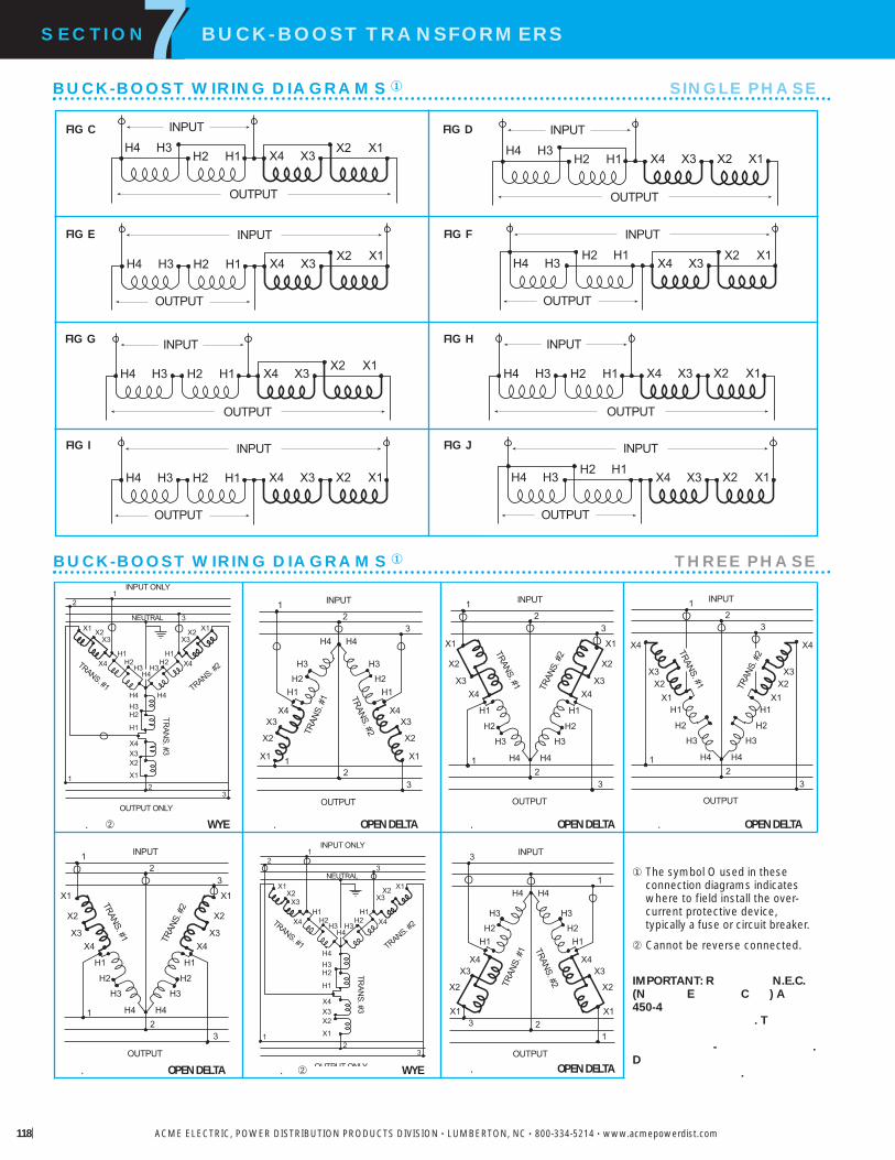
INPUT ONLY
OUTPUT ONLY
12
3
12
3
H4H3
H2H1
X4
X3X2X1
H4
H3H2
H1X4
X3X2 X1
H4H3H2
H1
X4X3X2
X1
TRANS. #1 TRANS. #2
TRAN
S. #3
NEUTRAL
H4
H1
H3
H2
X4
X1
X3
X2
INPUT
OUTPUT
12
3
12
3H4
H3
H2H1
X4X3
X2
X1
TRANS. #2TRAN
S. #
1
H4
H1
H3
H2
X4
X1
X3
X2
INPUT
OUTPUT
12
3
12
3
H4
H3
H2
H1
X4X3
X2
X1
TRANS. #1 TRAN
S. #
2
H4
H1
H3
H2
X4
X1
X3X2
INPUT
OUTPUT
12
3
12
3
H4
H3
H2
H1
X4
X3X2
X1
TRANS. #1 TRAN
S. #
2
H4
H1
H3
H2
X4
X1
X3
X2
INPUT
OUTPUT
12
3
12
3
H4
H3
H2
H1
X4X3
X2
X1
TRANS. #1 TRAN
S. #
2
INPUT ONLY
OUTPUT ONLY
12
3
12
3
H4H3
H2H1
X4
X3X2
X1
H3H2
H1X4
X3X2 X1
H4H3H2
H1
X4X3X2
X1
TRANS. #1 TRANS. #2
TRAN
S. #3
NEUTRAL
H4
H1
H3
H2
X4
X1
X3
X2
INPUT
OUTPUT
123
3
1H4
H3
H2H1
X4X3
X2
X1
TRANS. #2TRAN
S. #
1
. � WYE . OPEN DELTA . OPEN DELTA . OPEN DELTA
. OPEN DELTA . � WYE . OPEN DELTA
� The symbol O used in these connection diagrams indicates where to field install the over-current protective device,typically a fuse or circuit breaker.
� Cannot be reverse connected.
IMPORTANT: R N.E.C.(N E C ) A450-4
. T
- .D
.
SECTION BUCK-BOOST TRANSFORMERS7
ACME ELECTRIC, POWER DISTRIBUTION PRODUCTS DIVISION • LUMBERTON, NC • 800-334-5214 • www.acmepowerdist.com118
BUCK-BOOST WIRING DIAGRAMS� SINGLE PHASE
H4H1
H3H2 X4
X1X3
X2
INPUT
OUTPUT
H4 H1H3 H2 X4X1
X3X2
INPUT
OUTPUT
H4 H1H3 H2 X4X1
X3X2
INPUT
OUTPUT
H4 H1H3 H2 X4 X1X3 X2
INPUT
OUTPUT
H4H1
H3H2 X4 X1X3 X2
INPUT
OUTPUT
H4H1
H3H2
X4X1
X3X2
INPUT
OUTPUT
H4 H1H3 H2 X4 X1X3 X2
INPUT
OUTPUT
H4H1
H3H2
X4 X1X3 X2
INPUT
OUTPUT
FIG D
FIG F
FIG C
FIG E
FIG G FIG H
FIG JFIG I
BUCK-BOOST WIRING DIAGRAMS� THREE PHASE

S E C T I O N
304 Stainless Steel Panel Tran® . . . . . . . . .120-121
Features . . . . . . . . . . . . . . . . . . . . . . . . . . . . . . .120
Selection Charts–Single Phase . . . . . . . . . . . . .122
Selection Charts–Three Phase . . . . . . . . . . . . .123
Circuit Breaker Data–Single Phase . . . . . . . . . .122
Circuit Breaker Data–Three Phase . . . . . . . . . .123
Wiring Diagrams . . . . . . . . . . . . . . . . . . . . . . . .124
8
P NEL TR N®
ONE PO ERCENTERS
NEW
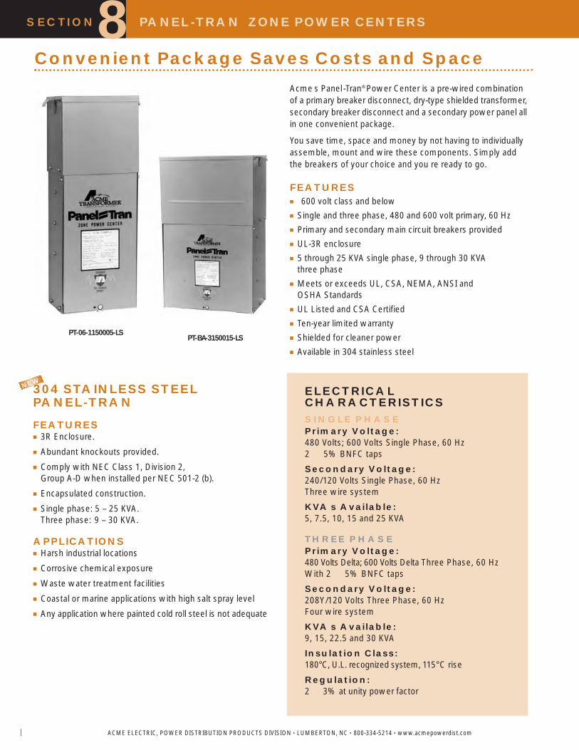
SECTION PANEL-TRAN ZONE POWER CENTERS8
ACME ELECTRIC, POWER DISTRIBUTION PRODUCTS DIVISION • LUMBERTON, NC • 800-334-5214 • www.acmepowerdist.com
Convenient Package Saves Costs and Space
ELECTRICALCHARACTERISTICSSINGLE PHASEPrimary Voltage:480 Volts; 600 Volts Single Phase, 60 Hz2 5% BNFC taps
Secondary Voltage:240/120 Volts Single Phase, 60 HzThree wire system
KVA s Available:5, 7.5, 10, 15 and 25 KVA
THREE PHASEPrimary Voltage:480 Volts Delta; 600 Volts Delta Three Phase, 60 HzWith 2 5% BNFC taps
Secondary Voltage:208Y/120 Volts Three Phase, 60 HzFour wire system
KVA s Available:9, 15, 22.5 and 30 KVA
Insulation Class:180°C, U.L. recognized system, 115°C rise
Regulation:2 3% at unity power factor
PT-06-1150005-LSPT-BA-3150015-LS
Acme s Panel-Tran® Power Center is a pre-wired combinationof a primary breaker disconnect, dry-type shielded transformer,secondary breaker disconnect and a secondary power panel allin one convenient package.
You save time, space and money by not having to individuallyassemble, mount and wire these components. Simply addthe breakers of your choice and you re ready to go.
FEATURES� 600 volt class and below� Single and three phase, 480 and 600 volt primary, 60 Hz� Primary and secondary main circuit breakers provided� UL-3R enclosure� 5 through 25 KVA single phase, 9 through 30 KVA
three phase� Meets or exceeds UL, CSA, NEMA, ANSI and
OSHA Standards� UL Listed and CSA Certified� Ten-year limited warranty� Shielded for cleaner power� Available in 304 stainless steel
304 STAINLESS STEEL PANEL-TRAN
FEATURES� 3R Enclosure.� Abundant knockouts provided.� Comply with NEC Class 1, Division 2,
Group A-D when installed per NEC 501-2 (b).� Encapsulated construction.� Single phase: 5 – 25 KVA.
Three phase: 9 – 30 KVA.
APPLICATIONS� Harsh industrial locations� Corrosive chemical exposure� Waste water treatment facilities� Coastal or marine applications with high salt spray level� Any application where painted cold roll steel is not adequate
NEW

ACME ELECTRIC, POWER DISTRIBUTION PRODUCTS DIVISION • LUMBERTON, NC • 800-334-5214 • www.acmepowerdist.com 121
SECTION PANEL-TRAN ZONE POWER CENTERS8UL-3R Enclosures All Panel-Tran® enclosures are UL-3Rlisted for indoor and outdoor use.
Transformer Assembly Acme totally encapsulateddistribution transformers are designed for general purposeindoor/outdoor operation. Panel-Tran® can be installed in a widevariety of atmospheric and environmental conditions. A 180°C,U.L. recognized insulation system is used.
Panel -Tran® units are electrostatically shielded to providetransient voltage protection at no extra cost.
Panel Assembly The power panel assembly willaccommodate one-inch, 1, 2 or 3-pole, common trip, duplexsecondary branch circuit breakers and ground fault circuitbreakers. Per UL and NEC requirements, the Panel-Tran®
assembly comes fully equipped with primary and secondarymain circuit breakers. Branch circuit breakers should be obtainedfrom our local distributor once you have established your branchcircuit requirements.
Panel-Tran Why? Panel-Tran® eliminates the normaltangled masses of secondary circuit feeders and gives yourindustrial/commercial distribution systems new flexibility. Useyour high voltage bus to full advantage by putting power wherethe problem is. Reduce cost save space keep flexible.
Panel-Tran Where? Anywhere 120, 208 or 240 voltbranch circuits are required. Typically, Panel-Tran® is best appliedin situations similar to the following: Powering foreman centers,vending machine areas, factory test set- ups, office buildings,mining applications, assembly lines, portable or temporary powersources, parking lots, small machine set-ups, light industrialareas, warehouses, and numerous other locations. Use whereyour branch circuits may require future change or expansion.
UL Listed Panel-Tran® has been listed by UnderwritersLaboratories for both indoor and outdoor operation under theirunit substation classification, file number E-56936. In addition,Panel-Tran® is U.L. listed as suitable for use as ServiceEntrance Equipment.
Meets The NEC Panel-Tran® fully complies with Article450-3 of the latest edition of the NEC.
Protection A primary main breaker protects the transformerand acts as a disconnect device. This primary main breakerhas a high interrupting capacity to handle fault conditions. Asecondary main breaker, between the transformer and thepanel, is required by the N.E.C.
Branch Circuits Typical 1" snap in circuit breakers, regularor duplex, must be field installed.They are not provided with thePanel-Tran® unit. A secondary ground is provided within thewiring compartment for accepting your branch unit. All ofthe breakers, including the primary main, secondary main, andbranch circuit breakers are located in the lower section of thePanel-Tran®. This lower section is protected by a hinged,removable front cover which can be padlocked for safety.
Recommended Branch Breakers We suggestusing branch breakers of the same manufacture as the panel inPanel-Tran®. Please contact the factory for the proper branchbreaker recommendation.
A .
Connections All Panel-Tran® connections will acceptcopper or aluminum conductor.
PM
SM
H RC
T -P P -L
C H
SC
FEATURES

SECTION PANEL-TRAN® ZONE POWER CENTERS8
ACME ELECTRIC, POWER DISTRIBUTION PRODUCTS DIVISION • LUMBERTON, NC • 800-334-5214 • www.acmepowerdist.com122
SELECTION CHARTS SINGLE PHASE
��The number of secondary circuits shown is only a representation of circuits. Please contact the factory for exact number of secondary circuits available.� 18,000 Amps RMS Symmetrical Interrupting Capacity.
Circuit Breaker Data�
480 PRIMARY VOLTS 240/120 SECONDARY VOLTS 1 , 60 Hz
GROUP I
GROUP I 304 SS304 STAINLESS STEEL480 PRIMARY VOLTS 240/120 SECONDARY VOLTS 1 , 60 Hz
480 VOLTS TO 240/120 VOLTS
MA IMUM SECONDAR APPRO DIMENSIONS APPROCIRCUITS� INCHES CM NET EIGHT
KVA CATALOG NO 120 V 240 V HEIGHT IDTH DEPTH LBS KG1 POLE 2 POLE
5.0 06 1150005 8 4 32.13 81.6 13.25 33.7 7.63 19.4 120 54.4
7.5 06 1150007 8 4 32.13 81.6 15.88 40.3 11.00 27.9 160 72.6
10.0 06 1150010 8 4 34.38 87.3 15.88 40.3 11.00 27.9 185 83.9
15.0 06 1150015 12 6 34.38 87.3 17.13 43.5 12.38 31.4 240 109.0
25.0 06 1150025 20 10 41.88 106.4 17.88 45.4 13.50 34.3 330 150.0
480 VOLTS 240 120 VOLTS MA IMUM RATING1 PRIMAR SECONDAR OFKVA BREAKER MAIN SECONDAR BREAKERS
5.0 42 025 25 225 25 20
7.5 42 025 25 240 40 30
10.0 42 035 35 250 50 40
15.0 42 050 50 270 70 60
25.0 42 090 90 2125 125 100
NEW

Circuit Breaker Data�
480 VOLTS DELTA TO 208Y/120 VOLTS
ACME ELECTRIC, POWER DISTRIBUTION PRODUCTS DIVISION • LUMBERTON, NC • 800-334-5214 • www.acmepowerdist.com
SECTION PANEL-TRAN ZONE POWER CENTERS8SELECTION CHARTS THREE PHASE
GROUP A
��The number of secondary circuits shown is only a representation of circuits. Please contact the factory for exact number of secondary circuits available.� 10,000 Amps RMS Symmetrical Interrupting Capacity.
480 DELTA PRIMARY VOLTS –– 208Y/120 SECONDARY VOLTS –– 3Ø, 60 Hz
GROUP A – 304 SS304 STAINLESS STEEL480 DELTA PRIMARY VOLTS –– 208Y/120 SECONDARY VOLTS –– 3Ø, 60 Hz
MAX. SECONDARY CIRCUITS � APPROX. DIMENSIONS APPROX.1Ø 3Ø INCHES (CM.) NET WEIGHT
KVA CATALOG NO. 120 V 208 V HEIGHT WIDTH DEPTH LBS. (KG.)(1-Pole) (3-Pole)
9.0 3150009 12 4 33.75 85.7 22.13 56.2 7.63 19.4 255 116.0
15.0 3150015 12 4 35.13 89.2 22.13 56.2 12.38 31.4 385 175.0
22.5 3150022 18 6 38.25 97.2 30.25 76.8 13.38 34.0 535 243.0
30.0 3150030 24 8 43.75 111.1 33.00 83.8 13.75 34.9 680 308.0
MA SECONDAR CIRCUITS� APPRO DIMENSIONS APPRO1 3 INCHES CM NET EIGHT
KVA CATALOG NO120 V 208 V HEIGHT IDTH DEPTH LBS KG1 P 3 P
9.0 3150009 12 4 33.75 85.7 22.13 56.2 7.63 19.4 255 116.0
15.0 3150015 12 4 35.13 89.2 22.13 56.2 12.38 31.4 385 175.0
22.5 3150022 18 6 38.25 97.2 30.25 76.8 13.38 34.0 535 243.0
30.0 3150030 24 8 43.75 111.1 33.00 83.8 13.75 34.9 680 308.0
NEW
3 480 VOLTS 208 120 VOLTS MA IMUM RATINGPRIMAR SECONDAR OF
KVA BREAKER MAIN SECONDAR BREAKERS
9.0 43 025 25 330 30 25
15.0 43 040 40 350 50 40
22.5 43 070 70 370 70 60
30.0 43 090 90 3100 100 80

SECTION PANEL-TRAN ZONE POWER CENTERS8
ACME ELECTRIC, POWER DISTRIBUTION PRODUCTS DIVISION • LUMBERTON, NC • 800-334-5214 • www.acmepowerdist.com124
Wiring Diagram 1 5-25 KVA
X1
H1
X2X3
H3 H4H2
LINE 1 LINE 2
GROUNDWHEN
REQUIREDBONDWHEN
REQUIRED
NEUTRAL
1 342
3 9 KVA 3 15-30 KVA
X3
GROUNDWHEN
REQUIRED
BONDWHEN
REQUIRED
X1
H5
X2
H3H4 H7
LINE B LINE C
NEUTRAL
H1 H3H2
123123 123
X1 X2 X3X0
H6H9H2 H1H8
LINE A LINE A LINE CLINE B
1 45263
1 78293
4 10115126
BONDWHEN
REQUIRED
NEUTRAL
PRIMARY MAINFURNISHED
SECONDARY MAINFURNISHED
BRANCH CIRCUITBREAKERS ARE
ADDED BY INSTALLER
X0
GROUNDWHEN
REQUIRED
PANEL-TRAN ZONE POWER CENTERS WIRING DIAGRAMS SINGLE PHASE
PANEL-TRAN ZONE POWER CENTERS WIRING DIAGRAMS THREE PHASE

SECTION
Construction Features . . . . . . . . . . . . . . . . . . .126
Selection Instructions . . . . . . . . . . . . . . . . . . . .127
Selection Charts . . . . . . . . . . . . . . . . . . . . . . . .128
AIR CONDITIONING,REFRIGERATION
& APPLIANCE TRANSFORMERS
9

SECTION AIR CONDITIONING,REFRIGERATION & APPLIANCE TRANSFORMERS9
ACME ELECTRIC, POWER DISTRIBUTION PRODUCTS DIVISION • LUMBERTON, NC • 800-334-5214 • www.acmepowerdist.com126
The transformers in this section are autotransformersdesigned to change a wide range of voltages to the standardmotor voltages for domestic appliances, air conditioners,and related equipment.
Correcting high or low supply voltage conditions to matchthe voltage requirements of appliances and equipment aidsin safe, efficient operation.
These Acme autotransformers change or correct off-standardvoltage that may be the result of:
1. Line supply voltage not matching the appliance motor nameplate voltage, (e.g., supply voltage is 380Y/220V, three phase, four wire. Appliance motor operates on 110 V, single phase. See schematic).
2. Low voltage due to inadequate wiring capacity in the electrical distribution system.
3. Low voltage caused by distribution of power over a long distance.
4. High or low voltages supplied by the utility company.
Standard voltages and frequencies (Hz) vary throughoutmany countries of the world. Since these autotransformers
are suitable for 50/60 Hz (cycle) service, they are applicablein export trade where it is necessary to change to a standardvoltage for appliance operation.
These transformers are capable of adjusting voltage only;they can t change the frequency of a supply circuit. However,in most instances, 60 Hz (cycle) equipment can be operatedfrom a 50 Hz supply if the voltage is reduced approximately8 -10%. For example, 115 V, 60 Hz equipment can usuallybe operated on 50 Hz at 105 V.
Some common uses for Acme Air Conditioning, Refrigerationand Appliance transformers include adjustment of off-standardvoltage to the nominal voltages required to operate:
) Air conditioners, television receivers, all home appliances.
) Hermetically sealed refrigeration motors.
) Individual machine lighting, tool post grinders, fans, convenience outlets for portable lights, power tools.
) Magnetic contactors, relays, AC motors and similar devices requiring large starting (inrush) currents.
Acme appliance transformers are autotransformers. The input(primary) winding is in electrical series connection with theoutput (secondary) winding; the input and output are notelectrically isolated.
The autotransformer principle is the most economical forappliance applications, since only the difference betweeninput voltage and output voltage is transformed. This resultsin smaller size, reduced weight and lower cost.
All units are constructed of core lamination processed fromannealed electrical grade silicon steel. This improves trans-former efficiency by keeping heat losses at a minimum.
Coils are precision machine wound and hand finished. Thecore and coil combination is impregnated with electrical gradevarnish, then heat cured. This provides cool operation andprotects the transformer from moisture and contamination.The result is long transformer life.
Air Conditioning, Refrigeration & Appliance Transformers
380V
N
A
380Y/220V, 3Ø4 WIRE SUPPLY
220V110V
ACMEAPPLIANCE
TRANSFORMER
LOAD(MOTOR, APPLIANCE, ETC.)
Construction Features

ACME ELECTRIC, POWER DISTRIBUTION PRODUCTS DIVISION • LUMBERTON, NC • 800-334-5214 • www.acmepowerdist.com
SECTION AIR CONDITIONING,REFRIGERATION & APPLIANCE TRANSFORMERS9
1. Determine the value of incoming line supply voltage and frequency (50 or 60 Hz).
2. Find the appliance or load equipment voltage rating and amperes from the nameplate or instruction sheet. Multiplythe two to obtain VA requirement of the load. If the powerrequirements are listed only in watts, consider this the sameas VA. (Exception: electric discharge lighting such as mercuryvapor, fluorescent, etc. should always be sized by volts x amps (VA). If only wattage ratings are known, double this requirement to obtain VA ratings of transformers needed).
3. Add all VA requirements of equipment to obtain total load. (All components must be of same voltage rating).
4. Add 10% for high starting current and overloading to obtain VA size of transformers.
5. Select transformer from charts on following pages using combination of supply voltage (primary), voltage rating of equipment (secondary), load VA rating, and type of connections desired.
Catalog # T-1-60812
Selection Steps
S R
6 (1.8 M) P C
The transformers in this section will not cause harmonicdistortion to voltage or current wave shape.
All transformers in Groups A and C are equipped with aSAFETY grounding feature on both the input and output side.
Connection for ground may be made through lead wires orthrough plug and receptacle combinations where installed.
All units are manufactured and tested in accordance withNational Electrical Manufacturers Association standards.
Some groups are equipped with primary voltage taps whichcorrect for voltage conditions constantly above or below thenominal rating of the supply.

SECTION AIR CONDITIONING,REFRIGERATION & APPLIANCE TRANSFORMERS9
ACME ELECTRIC, POWER DISTRIBUTION PRODUCTS DIVISION • LUMBERTON, NC • 800-334-5214 • www.acmepowerdist.com
GROUP C PRIMARY VOLTS — 200/220/240 SECONDARY VOLTS — 115, 50/60 Hz RECEPTACLE
CATALOG VA OUTPUT APPRO DIMENSIONS APPRONO RATING AMPS INCHES CM SHIP EIGHT CONNECTIONS
HEIGHT IDTH DEPTH LBS KG FEET METERS
1 60830 � 200 1.74 9.16 23.3 3.89 9.9 3.67 9.3 6 2.7 6 1.8
1 60831 � 300 2.61 9.16 23.3 3.89 9.9 3.67 9.3 6 2.7 6 1.8
1 60832 � 400 3.48 9.16 23.3 3.89 9.9 3.67 9.3 8 3.6 6 1.8
1 60833 � 500 4.35 9.68 24.6 4.75 12.1 4.51 11.5 10 4.5 6 1.8
1 60834 � 1000 8.70 9.68 24.6 4.75 12.1 4.51 11.5 14 6.4 6 1.8
1 60835 � 2000 17.40 11.50 29.2 7.81 19.8 7.13 18.1 27 12.2 6 1.8
GROUP A PRIMARY VOLTS 95/105/115/125/200/220/240/260 SECONDARY VOLTS 105 @ 50 Hz, 115 @ 60 Hz
� All models can be reverse connected with input voltage applied to secondary terminals and output voltage available at primary terminals.Do not exceed rating voltages. Transformer VA capacity will remain the same.
� Electrical Tap Connections Do not exceed +5% of nominal voltage without changing taps.
RECEPTACLE
CATALOG � VA OUTPUT APPRO DIMENSIONS APPRONO RATING AMPS INCHES CM SHIP EIGHT CONNECTIONS
HEIGHT IDTH DEPTH LBS KG FEET METERS
1 60800 � 350 3.04 9.16 23.3 3.89 9.9 3.67 9.3 8 3.6 6 1.8
1 60801 � 550 4.78 9.68 24.6 4.75 12.1 4.51 11.5 10 4.5 6 1.8
1 60802 � 750 6.51 9.68 24.6 4.75 12.1 4.51 11.5 11 5.0 6 1.8

SECTION
True-Power Constant VoltageRegulators and Portable Power LineConditioners; Portable .250 2.0 KVAand Hardwire .250 15.0 KVA
True-Power® Products . . . . . . . . . . . . . . . . . . . .130
Specifications . . . . . . . . . . . . . . . . . . . . . . . . . .131
Selection Charts . . . . . . . . . . . . . . . . . . . . . . . .131
Dimensional Drawings . . . . . . . . . . . . . . . . . . .132
PO ERCONDITIONING
PROD CTS
10

Acme True-Power® products consist of speciality designed fer-roresonant transformers. Although ferroresonant transformershave been an economical solution to power problems for manyyears, it took the skills of Acme s highly regarded engineeringstaff to refine it to meet today s exacting requirements.
For example, typical ferroresonant transformers have an inputlimited to 100 -130 V. Acme s True -Power® units have an inputrange of +10/-20% around input voltage nominals of 120/208/240and 480 volts. At 120 volt input, this relates to 95-130 volts.
The typical ferroresonant transformer has limited electrical noisesuppression capability. True-Power® power line conditionershave the following noise attenuation capability:
Common Mode: 120 dbTransverse Mode: 60 db
The typical ferroresonant transformer has an audible hum thatcan be objectionable in most offices. Acme s True-Power®
power line conditioners are encapsulated in epoxy to lowersound levels below ANSI standard C 89.2.
The typical ferroresonant transformer has on output regulationof ± 3% for input line changes only. Acme s True-Power® powerline conditioners have an output regulation of ± 3% for inputline and load changes, making them suitable for operation atany load condition.
FEATURES� Reliable, regulated output voltage when input voltage varies,
even to brownout levels.� Extended operation to 65% of nominal when operated at
60% of full load.� Noise rejection effectively suppressing transient spikes and
surges 120 db common mode and 60 db transverse mode.� Rapid response to line and load changes 5% variation in
8m sec, 10% variation in 16m sec.� Hold up time of 3m sec for complete loss of input power.
� Inherent overload and short circuit protection,without thermo protectors, fuses or circuitbreakers, for immediate recovery when theoverload is removed.
� Sinusoidal output features, less than 3% har-monic distortion, improves input wave formswhich have total harmonic distortions ofgreater than 5%.
� Available in 250 through 15,000 VA in hard-wired and portable models.
� Hardwired models will handle multiple primary input voltages.
� Illuminated ON/OFF switch, multiple outputreceptacles and six foot input power cord onportable units.
� UL Listed.� CSA Certified (Hardwire models).
Product Selection Guide
SECTION CONSTANT VOLTAGE REGULATORS & POWER LINE CONDITIONERS
ACME ELECTRIC, POWER DISTRIBUTION PRODUCTS DIVISION • LUMBERTON, NC • 800-334-5214 • www.acmepowerdist.com
10
APPLICATIONS� Computers and Data Processing
Equipment� Point of Sale Terminals� Electronic Test Equipment� X-Ray Equipment� Critical Lighting Applications� Programmable Controllers� Security Systems� Microprocessor Controls� Communications Equipment� Photographic Equipment� Regulated DC Power Supplies� Electronic Cash Registers� Robotics� Numerical Controls
Acme True-Power Power Line ConditionersThe average computer installation, representing mini-computer,workstations or personal computers, experiences an average of 100power disturbances each month. These disturbances can causeequipment malfunction, loss of memory and inaccurate data, andin the worst cases complete failure of these delicate electronicdevices. Computer installation manuals recommend dedicatedservice lines, but these are expensive to install, offer minimal futureflexibility and do not provide total protection of the equipment.Acme offers a complete line of Power Protection Equipment.Refer to the Product Selection Guide for the product that bestmeets your requirements.
N : This section of the general catalog contains complete spec-ification and selection information on Acme s True-Power® powerline conditioners.
ShieldedPROBLEM ENCOUNTERED Isolation True- SPS UPS
T P

ACME ELECTRIC, POWER DISTRIBUTION PRODUCTS DIVISION • LUMBERTON, NC • 800-334-5214 • www.acmepowerdist.com 131
P = Portable
HARDWIRED MODELS CONSTANT VOLTAGE REGULATORS95-132 X 166-228 X 192-264 X 384-528 VOLT PRIMARY 120/208/240 VOLT SECONDARY 1 , 60 Hz
PORTABLE MODELS POWER LINE CONDITIONERS95-132 VOLT PRIMARY 120 VOLT SECONDARY 1 , 60 Hz
SPECIFICATIONS
F = Floor W = Wall
�Wall mounting brackets required for this size. Refer to Page 157.� All hardwired models will accommodate these primary input voltages.� Dimensions not suitable for construction. Contact factory.
SELECTION CHARTS
GROUP I
GROUP II
Input (Primary) 95 13295 132 �
166 228192 264384 528
Phase: 1
Output (Secondary) 120120/208/240
Load Range 0 100Regulation 3 /Attenuation 120
60Audible Noise . 89.2
APPROX. DIMENSIONSKVA CATALOG INCHES (CM.) TYPE APPROX. FIGURE ELECTRICALSIZE NUMBER A B C D E MTG. SHIP WEIGHT CONNECTIONS
HEIGHT WIDTH DEPTH LBS. (KG.)0.25 85000 8.13 6.31 11.38 5.25 5.69 29 . 15 .
20.7 16.0 28.9 13.3 14.5 13.20.50 85001 9.13 7.50 13.63 6.38 7.19 45 . 15 .
23.2 19.1 34.6 16.2 18.3 20.40.75 85002 10.94 7.50 15.63 6.38 7.19 60 . 15 .
27.8 19.1 39.7 16.2 18.3 27.21.00 85003 10.94 10.69 17.63 8.31 10.88 72 . 15 .
27.8 27.2 44.8 21.1 27.6 32.72.00 85004 12.50 11.44 20.19 9.75 12.25 135 . 15 .
31.8 29.1 51.3 24.8 31.1 61.2
APPROX. DIMENSIONS� APPROX.KVA CATALOG INCHES (CM.) TYPE SHIP FIGURE WIRINGSIZE NUMBER A B C D E F G H J MTG. WEIGHT DIAGRAMS
HEIGHT WIDTH DEPTH LBS. (KG.) SEE PAGE 1470.25 1 69430 15.50 6.30 5.80 5.63 8.13 9.30 1.2 .41 .81 5.00 37 16
39.4 16.0 14.7 14.3 20.7 23.6 3.0 1.0 2.1 12.7 16.80.35 1 69431 17.00 7.00 7.30 5.63 8.13 9.40 2.3 .41 .81 6.50 51 16
43.2 17.8 18.5 14.3 20.7 23.9 5.8 1.0 2.1 16.5 23.10.50 1 69432 17.00 7.00 7.30 5.63 8.13 9.40 2.3 .41 .81 6.50 53 16
43.2 17.8 18.5 14.3 20.7 23.9 5.8 1.0 2.1 16.5 24.00.75 1 69433 17.00 7.00 7.30 5.63 8.13 9.40 2.3 .41 .81 6.50 65 16
43.2 17.8 18.5 14.3 20.7 23.9 5.8 1.0 2.1 16.5 29.51.00 1 69434 18.50 6.50 8.55 5.63 8.13 9.50 2.3 .41 .81 7.75 82 16
47.0 16.5 21.7 14.3 20.7 24.1 5.8 1.0 2.1 19.7 37.22.00 1 69435 19.00 10.50 10.20 6.00 12.00 13.25 2.3 .44 .63 9.40 142 16
48.3 26.7 25.9 15.2 30.5 33.7 5.8 1.1 1.6 23.9 64.43.00 1 69436 19.00 10.50 10.20 6.00 12.00 13.25 2.3 .44 .63 9.40 176 16
48.3 26.7 25.9 15.2 30.5 33.7 5.8 1.1 1.6 23.9 79.85.00 1 69437 22.00 12.54 12.20 6.00 14.00 15.25 2.3 .44 .63 11.40 295 16
55.9 31.9 31.0 15.2 35.6 38.7 5.8 1.1 1.6 29.0 134.010.00 1 69438 23.06 27.31 24.06 18.00 25.50 .56 � 605 16
58.6 69.4 61.1 45.7 64.8 1.4 274.015.00 1 69439 23.06 40.13 24.06 18.00 38.31 .56 880 16
58.6 101.9 61.1 45.7 97.3 1.4 399.0
SECTION CONSTANT VOLTAGE REGULATORS & POWER LINE CONDITIONERS10

ACME ELECTRIC, POWER DISTRIBUTION PRODUCTS DIVISION • LUMBERTON, NC • 800-334-5214 • www.acmepowerdist.com
FIGURE II & III
FIGURE IV
A
B
D
H
C
E
A
B
D
E
F
L
J
D
C
G
A
F
B
D
C
FRONT VIEW SIDE VIEW
FRONT VIEW SIDE VIEW
FRONT VIEW SIDE VIEW
SECTION CONSTANT VOLTAGE REGULATORS & POWER LINE CONDITIONERS10CONSTANT VOLTAGE REGULATORS DIMENSIONAL DRAWINGS
FIGURE I
POWER LINE CONDITIONERS DIMENSIONAL DRAWINGS

A leading source of high qualit linear and switch mode power supplies in enclosed and openframe st les.
DR Series Mounted Power SuppliesDin-Rail Mounted (DR Series)DR Series 1 to 10 Amps & Accessories . .134-136
DR Accessories . . . . . . . . . . . . . . . . . . . . . .137
Unregulated Linear PowerBlackline Series 100 Watts to 750 Watts . .138-139
Regulated Linear PowerSPS Blueline Series7.5 Watts to 144 Watts . . . . . . . . . . . . . . . . . .140-141
SPW Series 15 Watts to 175 Watts . . . . .142-143
DC PO ER S PPLIES
DC PO ER S PPLIES

DR SERIES DIN-RAIL MOUNTED POWER SUPPLIESSECTION
ACME ELECTRIC, POWER DISTRIBUTION PRODUCTS DIVISION • LUMBERTON, NC • 800-334-5214 • www.acmepowerdist.com
10DR Series 1.3 to 40 AmpsAcme s new flagship line of DR Series DC power supplies arean innovative solution to a vast array of control applications.Designed to provide optimal performance with a minimalimpact on installation time and space.
Available in single and three phase models, from 1.3 to 40Amps (31-960 watts) these new power supplies providethe convenience of DIN-rail mounting up to 10 Amp for atoolless installation and the versatility of a standard auto-ranging input to cover the most applications with the fewestmodels. The slim book profile greatly reduces the amountof space taken up on the DIN-rail and within the overallcontrol cabinet. The fully enclosed design is touch proof andCE compliant to meet international specifications and meetthe Power Factor Correction requirements of EN61000-3-2.All units are UL 508 listed and can be used at full-rated power.
Solution EaseThe DR families auto-ranging input feature provides youthe versatility of using one power supply to address inputvoltages from 90-265 volts for single phase applicationsand 360-550 on three phase applications automatically–no adjustments required during installation.
Space SavingAll the Acme Electric DR Series power supplies have beendesigned in a compact, slim book profile package compatiblewith other modules mounted in the control panel.
Installation Made EasyAll housings up to 10 Amps conveniently snap onto standard35 mm DIN-rail assuring permanent mounting without theuse of any tools. The 20 and 40 Amp housings are providedwith keyholes for mounting directly to the back panel foreasy installation while still benefiting from the slim bookprofile for maximum use of space.
FEATURES� Fully enclosed, low profile design� Touchsafe� Reduced installation time� Pluggable connections� Fast, easy wiring connections� Simplifies troubleshooting effort� DIN-rail Mounted� Mounts on standard DIN-rail� No tools required� Local output indication� Primary switching technology� Two-year limited warranty
DIN-Rail Mounted Power Supplies
INDUSTRIES� Automotive� Machine tool� Material handling� Packaging� Food processing� Panel builders� Automation
APPLICATIONS� Programmable Logic Controllers� CNC Equipment� Microprocessor Circuits� Digital and Analog Instrumentation� Industrial Control Applications
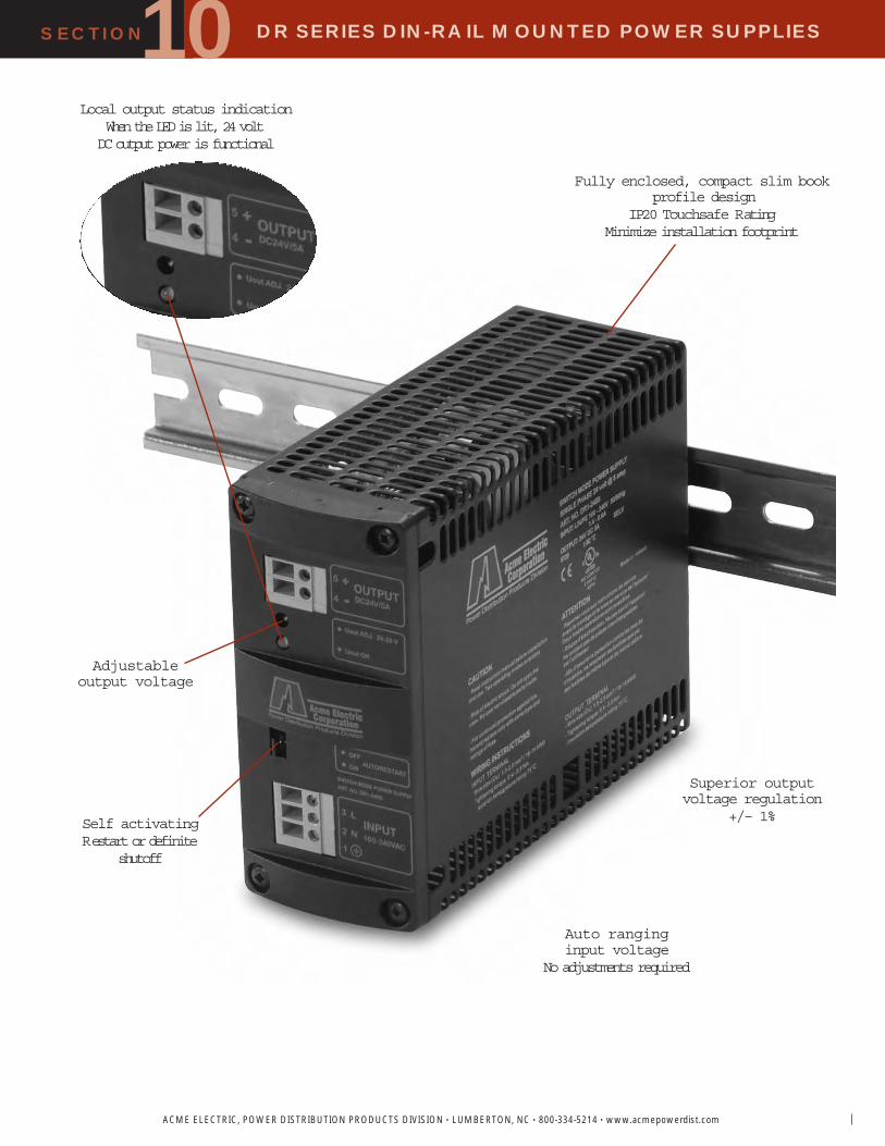
DR SERIES DIN-RAIL MOUNTED POWER SUPPLIES
ACME ELECTRIC, POWER DISTRIBUTION PRODUCTS DIVISION • LUMBERTON, NC • 800-334-5214 • www.acmepowerdist.com
SECTION10Fully enclosed, compact slim book
profile designIP20 Touchsafe Rating
Minimize installation footprint
Superior outputvoltage regulation
+/– 1%
Local output status indicationWhen the LED is lit, 24 volt DC output power is functional
Self activatingRestart or definite
shutoff
Auto ranginginput voltage
No adjustments required
Adjustableoutput voltage

DR SERIES DIN-RAIL MOUNTED POWER SUPPLIES
136
SECTION
ACME ELECTRIC, POWER DISTRIBUTION PRODUCTS DIVISION • LUMBERTON, NC • 800-334-5214 • www.acmepowerdist.com
10SINGLE PHASE
THREE PHASE
SELECTION GUIDES
SINGLE PHASE
THREE PHASE
H
D
H
D
1.3 Amps Single & Three Phase2.5-40 Amps
DR SERIES DIMENSIONAL DRAWINGS
V V OC N A R R AC R DC F V M L E UL CUL CE
1 24013 1.3 94 264 50/60 24 17 89 .
1 24025 2.5 90 265 110 300 50/60 24 24 28 17 85 .
1 2405 5 90 265 90 300 50/60 24 24 28 17 88 .
1 2410 10 90 265 90 300 50/60 24 24 28 17 88 .
1 2420 20 90 265 90 300 50/60 24 24 28 17 88 .
V V OC N A R R AC R DC F V M L E UL CUL CE
3 2405 5 3 360 550 50/60 24 24 28 17 90 .
3 2410 10 3 360 550 50/60 24 24 28 17 90 .
3 2420 20 3 360 550 50/60 24 24 28 17 90 .
3 2440 40 3 360 550 50/60 24 24 28 17 91 .
APPRO DIMENSIONS INCHES C EIGHT
C N H D LBS K
3 2405 5.00 12.7 7.01 17.8 2.68 6.8 2.87 1.3
3 2410 5.00 12.7 7.01 17.8 2.68 6.8 2.87 1.3
3 2420 8.23 20.9 8.94 22.7 3.31 8.4 5.07 2.3
3 2440 9.53 24.2 10.63 27.0 4.17 10.6 9.92 4.5
APPRO DIMENSIONS INCHES C EIGHT
C N H D LBS K
1 24013 2.99 7.6 2.91 7.4 1.50 3.8 0.33 0.1
1 24025 4.23 10.7 3.84 9.7 1.65 4.2 0.99 0.4
1 2405 4.53 11.5 5.94 15.1 2.13 5.4 1.65 0.7
1 2410 5.00 12.7 8.03 20.4 2.68 6.8 3.31 1.5
1 2420 8.23 20.9 9.17 23.3 3.31 8.4 5.95 2.7

DR SERIES DIN-RAIL MOUNTED POWER SUPPLIES
ACME ELECTRIC, POWER DISTRIBUTION PRODUCTS DIVISION • LUMBERTON, NC • 800-334-5214 • www.acmepowerdist.com
SECTION10
3 5
4
L
N2
1
DC+
DC-
Part No. DR1-2405
3 5
4
L
N2
1
DC+
DC-
Part No. DR1-2405 DC24V
AC115-230V
PE
10DESCRIPTIONSPackaged in a touch-proof enclosure to eliminate the possibilityof accidental shock. The universal mounting foot allows theoutlet box to be mounted either vertically or horizontally inyour panel. Touch-proof screw terminal block provides areliable connection.
FEATURES� DIN-rail mount duplex receptacle� Vertical or horizontal mounting� Snap on foot provides fast installation or can be fixed with
screws in control cabinet� Fits on 35 mm wide DIN-rail� Ground prong reversed for greater protection� Screw terminal connection via touch-proof terminal blocks� Available with GFI (Ground Fault Interrupting)� UR Recognized
APPLICATIONS� Test & Diagnostic Equipment� Computers/Printers� Power Tools� Soldering Iron� Displays� Lighting� Fan
For critical load applicationsredundancy may be requiredAll the DR Series power supplies can be connected in parallelfor redundancy, so if one power supply fails, there is adequatepower reserve in the remaining unit to continue supportingthe critical load (Reference Figure 1).
Redundancy Applications
GENERAL SPECIFICATIONSTechnical DataRated Voltage . . . . . . . . . . . . . . . . . . . . . . .120 V ACRated Current . . . . . . . . . . . . . . . . . . . . . . .15 or 20 AMPSMaximum Wire Size . . . . . . . . . . . . . . . . . .#10 AWG
Housing DataColor . . . . . . . . . . . . . . . . . . . . . . . . . . . . . .BlackMaterial . . . . . . . . . . . . . . . . . . . . . . . . . . .PVC V01550Maximum Temperature . . . . . . . . . . . . . . .40° C
DimensionsLength . . . . . . . . . . . . . . . . . . . . . . . . . . . . . . . .5.32 in. (135 mm)Width . . . . . . . . . . . . . . . . . . . . . . . . . . . . . . . . .2.95 in. (75 mm)Depth . . . . . . . . . . . . . . . . . . . . . . . . . . . . . . . . .2.56 in. (65 mm)
DR Duplex Receptacle
DR Duplex Receptacle Selection Chart
AMPCATALOG APPROX.NUMBER SHIP WEIGHT LBS (Kg)
15 15 .41 .19
15 15 .46 .21
20 20 .41 .19
20 20 .46 .21
Figure 1

TYPICAL VDC OUTPUT(@ 115 VAC IN) AMPS
CATALOG NO. NO LOAD HALF LOAD FULL LOAD FULL LOAD
100 7 10.6 8.8 7.9 10.0
100 12 14.8 12.9 11.7 7.0
100 20 23.3 20.8 19.3 5.0
100 24 30.6 27.5 25.4 3.5
100 48 56.3 51.0 47.9 1.8
200 7 12.3 9.5 8.2 20.0
200 12 15.4 12.5 11.3 15.0
200 20 26.8 22.5 20.3 10.0
200 24 34.4 29.5 27.1 7.5
200 48 58.9 48.2 46.5 4.0
500 24 31.0 28.4 26.7 20.0
500 48 59.7 50.2 47.8 10.0
750 24 33.3 27.7 25.5 30.0
750 48 58.5 49.7 48.5 15.0
DC POWER SUPPLIES
138
SECTION
ACME ELECTRIC, POWER DISTRIBUTION PRODUCTS DIVISION • LUMBERTON, NC • 800-334-5214 • www.acmepowerdist.com
1010The Blackline series of Bulk DC power supplies havehigh surge current capability, floating output, thermaldissipation, and computer grade capacitors –– all in anopen frame construction. Units are UL recognized.
FEATURES� High Surge Current Capabilities� MTBF to 500,000 hours per MIL 217E� Maximum efficiency to 90%� UL recognized to UL 1950� FCC Level B EMI� Floating output� High quality transformer � Open-frame construction� Thermal dissipation� Computer-grade capacitors� Recognized to UL
APPLICATIONS� DC Motors� DC Relays� Industrial Machinery� Battery Chargers� Solenoids
ELECTRICAL SPECIFICATIONSAC INPUTInput voltage is selectable by transformer taps for 115 or230 Vac (10% taps are provided).
DC OUTPUTVOLTAGE RATINGS: 7, 12, 16, 20, 24, 48 Volts
MAXIMUM RIPPLE: 3% rms at nominal line voltage,at full rated load
®CUnregulated Linear Power Supplies
Blackline Series 100 Watts to 750 Watts Bulk DC Linear Power

TAP NOMINAL HIGH-LINE JUMPER(Vac) (Vac) (Vac) CONNECTION
115 10 103.5 113.9 1
115 115.0 126.5 2
115 10 126.5 139.2 3
230 10 207.0 227.7 4
230 230.0 253.0 5
230 10 253.0 278.3 6
A B0 B1 C D E F G H MTG. WEIGHTDIA.
SERIES In. (mm) In. (mm) In. (mm) In. (mm) In. (mm) In. (mm) In. (mm) In. (mm) In. Lbs. (kg)
15 4.62 117.3 4.00 101.6 .31 7.9 2.09 53.1 1.60 40.6 .31 7.9 2.75 69.8 .20 1.7 0.8
30 5.88 149.3 5.38 136.6 .25 6.3 2.72 69.1 2.19 55.6 .31 7.9 3.25 82.5 .22 2.6 1.2
60 6.25 158.7 5.65 143.5 5.15 130.8 .25 6.3 3.00 76.2 2.73 69.3 .35 8.9 3.71 94.2 .22 4.0 1.8
100 7.12 180.8 6.42 163.1 5.87 149.1 .35 8.9 3.25 82.5 2.88 73.1 .30 7.6 4.00 101.6 .22 6.7 3.0
200 8.10 205.7 7.50 190.5 6.90 175.3 .25 6.3 3.88 98.5 3.80 96.5 .30 7.6 5.00 127.0 .26 12.2 5.5
500 9.00 228.6 8.24 207.6 .35 8.9 4.62 117.3 2.50 63.5 1.56 39.6 5.62 142.7 .28 20.0 9.1
750 9.50 241.3 8.50 215.9 .50 12.7 5.56 141.2 6.62 168.1 .50 12.7 8.00 203.2 .28 28.5 12.9
ACME ELECTRIC, POWER DISTRIBUTION PRODUCTS DIVISION • LUMBERTON, NC • 800-334-5214 • www.acmepowerdist.com
SECTION DC POWER SUPPLIES10JUMPER CONNECTION
Electrical & Mechanical Specifications
1
1 2 3 4
5 6 7 8
G
D
A B1
C
F E H
B0
GT-
C20
1 T
60 100 200 .0 . 1 .
47 63 10 .
AC INPUT VOLTAGEInput voltage is selectable by transformer taps for 115 or 230Vac (10% taps are provided).

SECTION
ACME ELECTRIC, POWER DISTRIBUTION PRODUCTS DIVISION • LUMBERTON, NC • 800-334-5214 • www.acmepowerdist.com140
10
OUTPUTCATALOG NO VDC AMPS
3012 12 1.8
6012 12 5.0
12012 12 10.0
152428 24/28 0.8/0.6
302428 24/28 1.2/1.0
602428 24/28 2.5/2.0
1202428 24/28 6.0/5.0
Regulated Linear Power SuppliesSPS Blueline Series 2.0 to 144 Watts of DC Power
DC POWER SUPPLIES10The SPS Blueline series provides 15 to 120 watts of DCpower with adjustable output voltages and selectable inputsof 115/230 VAC, 47-440 Hz. Floating outputs on most modelsand optional OVP on most models for greater versatility.
FEATURES� Adjustable output voltage� Selectable input 120/240 Vac, 50/60 Hz� Wide operating temperature range� Remote sense capability on each output� Overvoltage protection available on all outputs� Overload protection with automatic recovery� UL Recognized, CSA Certified� Most outputs rated SELV
APPLICATIONS� Personal Computers� Instrumentation� Control Concepts� Data Processing� Microprocessor Circuits� Electronic Circuits
ELECTRICAL SPECIFICATIONSAC INPUTINPUT VOLTAGE: 120/(240) Vac on most models
INPUT FREQUENCY: 50/60 Hz
DC OUTPUTOUTPUT VOLTAGE/CURRENT: See selection chart
VOLTAGE ADJUSTMENT RANGE: + 5% minimumAll outputs are potentiometer adjustable(*) 120 Vac operation only
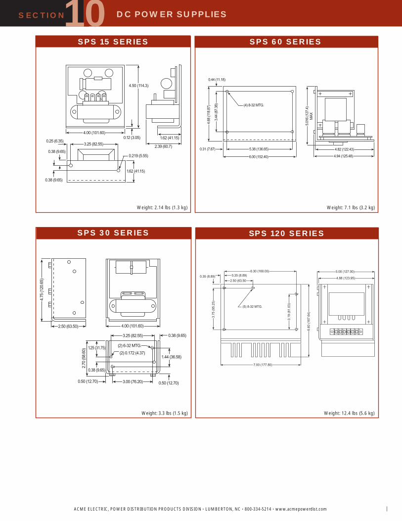
ACME ELECTRIC, POWER DISTRIBUTION PRODUCTS DIVISION • LUMBERTON, NC • 800-334-5214 • www.acmepowerdist.com
SECTION DC POWER SUPPLIES100.44 (11.18)
(4) 8-32 MTG.
4.68
(118
.87)
3.44
(87.
38)
0.31 (7.87) 5.38 (136.65)
6.00 (152.40)
4.82 (122.43)
4.94 (125.48)
5.01
6 (1
27.4
)
MAX
SPS 60 SERIES
Weight: 7.1 lbs (3.2 kg)
4.50 (114.3)
4.00 (101.60)1.62 (41.15)0.12 (3.05)
2.39 (60.7)3.25 (82.55)0.25 (6.35)
0.38 (9.65)
0.38 (9.65)
0.219 (5.55)
1.62 (41.15)
4.75
(120
.65)
2.50 (63.50) 4.00 (101.60)
3.25 (82.55) 0.38 (9.65)
1.44 (36.58)
(2) 6-32 MTG.
(2) 0.172 (4.37)
0.50 (12.70)3.00 (76.20)0.50 (12.70)
0.38 (9.65)
2.70
(58.
60) 1.25 (31.75)
6.30 (160.00)0.35 (8.89)
2.50 (63.500.35 (8.89)
3.75
(95.
25)
(5) 8-32 MTG.
3.19
(81.
03)
6.60
(167
.64)
7.00 (177.80)
5.00 (127.00)
4.88 (123.95)
SPS 15 SERIES
SPS 30 SERIES SPS 120 SERIES
Weight: 2.14 lbs (1.3 kg)
Weight: 3.3 lbs (1.5 kg) Weight: 12.4 lbs (5.6 kg)

142
DC POWER SUPPLIES
FEATURES� Worldwide AC input range� Worldwide safety standards� Industry standard package� Built-in OVP on 5V output� Optional OVP for other outputs� Overload protection with automatic recovery� 100% burn-in� Recognized to UL, CSA Certified, and CE Listed
APPLICATIONS� Personal Computers� Instrumentation� Control Concepts� Data Processing� Microprocessor Circuits� Electronic Circuits
ELECTRICAL SPECIFICATIONSAC INPUTINPUT VOLTAGE: 100/120/220/230/240 selectable
INPUT FREQUENCY: 47 to 63 Hz typical 60 Hz
DC OUTPUTOUTPUT ADJUSTMENT RANGE: + 5% minimum
Regulated Linear Power SuppliesSPW Series 15 Watts to 175 Watts
The SPW series regulated linear power supplies areaccepted world-wide for selectable AC input voltages of100 through 240 V and meet UL, CSA and TUV standards.These units have overload protection with automaticrecovery and 100% burn-in. All 5V output models havebuilt-in over voltage protection.
10
ACME ELECTRIC, POWER DISTRIBUTION PRODUCTS DIVISION • LUMBERTON, NC • 800-334-5214 • www.acmepowerdist.com
SECTION
OUTPUT 1CATALOG NO VDC AMPS
53 5 3.0
1217 12 1.7
2412 24 1.2
2424 24 2.4
2436 24 3.6
2448 24 4.8
2472 24 7.2
INPUT JUMPER INFORM TIONFOR USE AT 100Vac 120Vac 220Vac 230/240Vac
Jumper 1-3, 2-4 1-3, 2-4 2-3 2-3Apply AC 1 & 5 1 & 4 1 & 5 1 & 4

3.99
2 (1
01.4
)
3.37
0 (8
5.6)
.378
(9.6
)
.744
(18.
9)
.366 (9.3)
.39
(10.
0).188 (4.80) D. MTG HOLES (8 PLACES)
V ADJ.
ACINPUT
1.62 (41.0)
.744 (18.9)0.48 (12.2)
OVP(OPTIONAL)
DC OUTPUT
4.843 (123.0)
4.142 (105.2)
ACME ELECTRIC, POWER DISTRIBUTION PRODUCTS DIVISION • LUMBERTON, NC • 800-334-5214 • www.acmepowerdist.com
SECTION DC POWER SUPPLIES
NOTE: Dimensions are in inches (mm)
A CASE
Weight: 2.43 lbs (1.1 kg)
AC INPUT
4.87 (123.5)
4.118 (104.5)0.252 (6.4)
V ADJDC
OU
TPU
T
OVP
(OPT
ION
AL)
5.62
(142
.6)
4.87
5 (1
24.0
)0.
433
(11.0
)
2.50
(62.
8)
1.28
(32.
5)0.
72 (1
6.3)
.188 (4.8) D. MTG HOLES (12 PLACES)
.39 (10.0)
1.28 (32.5) 0.72 (18.3)
0.44 (11.2) MAX
Weight: 4 lbs (1.8 kg)
AC INPUT DC OUTPUT
7.0 (178.0) 6.25 (158.8) .38 (9.6)
4.
87 (1
23.7
)
4.
125
(104
.5)
.50 (12.7) .50 (12.9)
2.
75 (6
9.9)
1.
248
(31.
7)
.75
(19.
1)
OVP (OPTIONAL) .188 (4.8) D. MTG HOLES (16 PLACES)
.56 (4.2) MAX
.75 (19.1) 1.248 (31.7)
Weight: 7.28 lbs (3.3 kg)
OVP (OPTIONAL)
DC OUTPUT 3.00 (76.5)
11.00 (279.5)
7.50 (190.5)
DC OUTPUT1.25 (32.0) .75 (19.0)
.41 (10.5).185 (4.7)
COMM
V ADJV ADJ
V ADJ
4.0
(102
.0)
3.37
(56.
0)
.37 (9.5)
2.75
(70.
0)
.25
(32.
0)
.75 (19.0)
AC INPUT 4.80 (1.88) D. MTG HOLES (16 PLACES)
.39 (10.0)
Weight: 8.82 lbs (4 kg)
14.0 (355.60)
13.0 (330.20).50 (12.70)
4.12
5 (1
04.7
8)
.50 (12.70)
4.87
(123
.70)
.130 (3.30)
.65 (16.51).75 (19.05)
1.25 (31.75).188 (4.80) D. MTG HOLES (16 PLACES)
2.75 (69.85)
1.25 (31.75).75 (19.05)
AC INPUTDC OUTPUT
OVP OPTIONAL
Weight: 8.82 lbs (4 kg)
B CASE
C CASE D CASE
E CASE
10

SECTION DC POWER SUPPLIES
ACME ELECTRIC, POWER DISTRIBUTION PRODUCTS DIVISION • LUMBERTON, NC • 800-334-5214 • www.acmepowerdist.com144
10Q What is a power supply and what does it do?A A power supply is an electronic device that converts AC line power
to one or more individual DC outputs.
Q What is an unregulated power supply and where are they used?A An unregulated power supply provides DC voltage for applications
that do not require close tolerance DC output regulation. Typical applications for unregulated power supplies are DC motors, relays,and solenoids.
Q What is a regulated linear DC power supply and where are they used?A This is a power supply that, through additional circuitry,series pass
transistors and linear IC s; provides a regulated, low noise DC voltage. Typical applications are IC s, micro-processors, keyboards and disc drives.
Q How are the input connections made on linears?A All of the linear power supplies offered require the AC input to be
connected directly to the transformer.
Q How are the output connections made on linears?A All of the output connections on the linears are via solder barrett
terminals. The linears require the customer to solder directly to the turret terminals.
Q What is a switching power supply?A This is a supply which converts the AC source to a high voltage
(typically 350 VDC). This high voltage is used in turning on and off power switching transistors or MOSFETs to produce a DC currentand voltage. The high voltage and high switching frequency (20 KHzto 100 KHz) allows a switchmode power supply to be more efficient.That is, it needs less AC current to produce equivalent DC current thana linear power supply, resulting in less heat and a smaller package.
Q Can power supplies be operated at line frequencies other than 60 Hz?A Yes, the Standard Power line of DC power supplies operates on 50 to
60 Hz.
Q What is efficiency?A Efficiency is the ratio of the output power to input power. It is
generally measured at full load and nominal line conditions and expressed as a percentage.
Q What is overvoltage protection (OVP)?A Overvoltage protection is a protection mechanism for the load
circuitry that prevents the output voltage from exceeding apreset limit.
Q If a switcher s output shuts down the overvoltage protection circuit, can the unit turn on by itself?
A No, you must manually re-cycle (turn off, then turn on) the AC input power.
Q Do all power supplies require an AC ground?A Yes, all AC input connections require a ground. On the switching
power supplies, the ground is provided on the AC barrier strip or chassis. Linear power supplies have AC grounding directly on the transformer or chassis.
Q Can a power supply be loaded according to its wattage rating alone?A No, each output on a power supply is rated for voltage and current.
The power supply is selected for each application according to the voltage and current requirements.
Q What is meant by regulation in a power supply?A Regulation is the change in value of DC output voltage resulting
from a change in either the output s load or the AC line voltage.
Q What is a regulator?A The regulator is the part of the power supply that controls the
output voltage level when there is a change in the line or load.
Q What is remote sensing?A Remote sensing is a method of moving the point of regulation
from the output terminals to the load.
Q Why should the sense terminals be connected in either local or remote?
A If the sense leads are not connected, this could cause the outputvoltage to go high. If the output has over-voltage protection, the output will shut down.
Q Are there any special considerations that provisions must be made for when remote sensing?
A Yes, when remote sensing is used, the sense leads must be as short as possible and twisted to avoid picking up stray noise.
Q What is foldback current limit?A Foldback current limit is a protective circuit of the power supply
output. The foldback current limit is preset at 120% of the rated output current of the supply. If this output value is exceeded, thecircuit folds back the current so that only 40% of the rated current is delivered. This prevents the power supply from trying to deliver more than it is capable of and overheating.
Q If the current limit foldback is activated, does the power supply have to be manually reset?
A No, the unit will reset automatically.
Q What would be some possible causes of a power supply overheating?A A. Outputs overloaded.
B. Poor ventilation.C. Improper connection on primary side of transformer.D. AC input voltage too high.E. Power supply is running at full load in an environment that
exceeds temperature specs. The power supply should be derated.
Q What are floating outputs?A Floating outputs are outputs on the supply that do not share a
common return which enable the user to switch polarities.
Q What is switching frequency?A Switching frequency is the rate at which the high source voltage is
switched in a switching regulator.
Q What is the switching frequency of Standard Power switchers?A 20 to 100 KHz.
Q What is meant by the adjustment range of the output of a power supply?
A The adjustment range is how much the output of the supply can be adjusted or changed from its rated output. This is expressed as a percentage and is accomplished through the use of a potentiometer.
Q What is ripple?A Ripple or PARD, as it is sometimes referred to, is the Periodic and
Random Deviation of the output voltage. This is usually noise induced from other sources.
Q What is hold-up time?A Hold-up time is the total time an output will remain within its
regulation after the input line voltage has been turned off.
Q What is the mean time between failure (MTBF)?A The MTBF is the parameter used to compare the reliabilities of
power supplies. It is expressed in hours.
Q Are UL designations acceptable everywhere?A Not necessarily. There are similar agencies all over the world, but
their specifications for safety vary. Many of Standard Power s products are certified to CSA and CE licensed by TUV for IEC and VDE.
Frequently Asked Questions
Design Figures . . . . . . . . . . . . . . . . . . . . . . . . . . . . .146
Wiring Diagrams . . . . . . . . . . . . . . . . . . . . . . . .147-156
Transformer Accessories . . . . . . . . . . . . . . . . .157-158
Specification Guides . . . . . . . . . . . . . . . . . . . . .159-162
Industry Standards . . . . . . . . . . . . . . . . . . . . . . . . . .163
Alphanumerical Catalog Number Index . . . . . .164-168
ACMETRANSFORMER
GENERALINFORMATION
GENERAL

GENERAL ACME TRANSFORMER DESIGN FIGURES
ACME ELECTRIC, POWER DISTRIBUTION PRODUCTS DIVISION • LUMBERTON, NC • 800-334-5214 • www.acmepowerdist.com146
Design FiguresSections I, II, III & IV
D A
D B
D E
D H
D C D D
D F D G
D I
These drawings are for reference only.Contact factory for certified drawings.
D
H
W
D
H
W
D
H
W
D
H
W
D
H
W
D
H
W
D
H
W
D
H
W
D
H
W

ACME ELECTRIC, POWER DISTRIBUTION PRODUCTS DIVISION • LUMBERTON, NC • 800-334-5214 • www.acmepowerdist.com
GENERAL ACME® TRANSFORMER™ WIRING DIAGRAMS
PRIMARY: 240 X 480SECONDARY: 120/240TAPS: None
X4 X1
H4
H2H3
H1
X2 X3
Connect ConnectPrimary Primary Inter- SecondaryVolts Lines To Connect Lines To480 1 4 2 3
240 1 32 4
Secondary Volts240 2 3 1 4
120/240 2 3 1 2 4
120 1 3 1 42 4
PRIMARY: 240 X 480SECONDARY: 120/2402, 21/2% ANFC, 2, 21/2% BNFC
X4 X1
H10
H2 H3
H1
X2 X3
H5 H6
H8H7H4 H9
Connect ConnectPrimary Primary Inter- SecondaryVolts Lines To Connect Lines To
216 1 10 1 910 2
228 1 10 1 810 3
240 1 10 1 710 4
252 1 10 1 610 5
432 1 10 2 9444 1 10 3 9456 1 10 3 8468 1 10 4 8480 1 10 4 7492 1 10 5 7504 1 10 5 6
S V240 2 3 1 4
120/240 2 3 1 3 4
120 1 3 1 42 4
PRIMAR : 240 480SECONDAR : 120 240TAPS: 2 21 2 ANFC 2 21 2 BNFC
X4 X1
2
H1
X2 X3
H3
1 3
H4
4 5 6 7 8
H2
C CP P I SV L T C L T
216 1 4 1 3 82 4 1
228 1 4 1 3 72 4 2
240 1 4 1 3 62 4 3
252 1 4 1 3 52 4 4
432 1 4 2 1 3 8444 1 4 2 2 3 8456 1 4 2 2 3 7468 1 4 2 3 3 7480 1 4 2 3 3 6492 1 4 2 4 3 6504 1 4 2 4 3 5
S V240 2 3 1 4
120/240 2 3 1 2 4
120 1 3 1 42 4
PRIMAR : 208SECONDAR : 120 240TAPS: 2 5 BNFC
X4 X1
H1
X2 X3
H3
H4
H2
C CP P I SV L T C L T208 1 4198 1 3187 1 2
S V240 2 3 1 4
120/240 2 3 1 2 4
120 1 3 1 42 4
PRIMAR : 240 480SECONDAR : 120 240TAPS: 2 21 2 ANFC 2 21 2 BNFC
X4 X1
H8
H2 H3
H1
X2 X3
H4 H5
H6 H7
C CP P I SV L T C L T
252 1 8 1 54 8
240 1 7 1 53 7
228 1 6 1 52 6
504 1 8 4 5492 1 8 3 5480 1 7 3 5468 1 7 2 5456 1 6 2 5
S V240 2 3 1 4
120/240 2 3 1 2 4
120 1 3 1 42 4
PRIMAR : 240 480SECONDAR : 120 240TAPS: N
X4 X1
H4
H2H3
H1
X2 X3
C CP P I SV L T C L T480 1 4 2 3
240 1 32 4
S V240 2 3 1 4
120/240 2 3 1 2 4
120 1 3 1 42 4
1 2 3
6
54
Wiring DiagramsSections I, II, III & IV

GENERAL ACME TRANSFORMER WIRING DIAGRAMS
ACME ELECTRIC, POWER DISTRIBUTION PRODUCTS DIVISION • LUMBERTON, NC • 800-334-5214 • www.acmepowerdist.com148
PRIMARY: 120 x 240SECONDARY: 120/240TAPS: None
X4 X1
H4
H2H3
H1
X2 X3
Connect ConnectPrimary Primary Inter- SecondaryVolts Lines To Connect Lines To240 1 4 2 3
120 1 32 4
Secondary Volts240 2 3 1 4
120/240 2 3 1 2 4
120 1 3 1 42 4
PRIMARY: 600SECONDARY: 120/240TAPS: None
X4 X1
H1
X2 X3
H2
Connect ConnectPrimary Primary Inter- SecondaryVolts Lines To Connect Lines To600 1 2
Secondary Volts240 2 3 1 4
120/240 2 3 1 2 4
120 1 3 1 42 4
PRIMARY: 600SECONDARY: 120/240TAPS: None
X4 X1
H1
X2 X3
H2
Connect ConnectPrimary Primary Inter- SecondaryVolts Lines To Connect Lines To600 1 2
Secondary Volts240 2 3 1 4
120/240 2 3 1 2 4
120 1 3 1 42 4
PRIMARY: 277SECONDARY: 120/240TAPS: 2, 5% BNFC
X4 X1
H1
X2 X3
H3
H4
H2
Connect ConnectPrimary Primary Inter- SecondaryVolts Lines To Connect Lines To277 1 4263 1 3250 1 2
Secondary Volts240 2 3 1 4
120/240 2 3 1 2 4
120 1 3 1 42 4
EXPORT MODELPRIMARY: 190-220 x 380-440SECONDARY: 120/240
X4 X1
H5
H3
H1
X2 X3
H2 H4
H6
H7 H8 H9
H10
Connect ConnectPrimary Primary Inter- Secondary
Volts Lines To Connect Lines To
190 1 7 1 62 7
200 1 8 1 63 8
208 1 9 1 64 9
220 1 10 1 65 10
380 1 7 2 6400 1 8 3 6416 1 9 4 6440 1 10 5 6
Secondary Volts240 2 3 1 4
120/240 2 3 1 2 4
120 1 3 1 42 4
PRIMARY: 240SECONDARY: 120/240TAPS: None
1
1
2
3
3
Connect ConnectPrimary Primary Inter- SecondaryVolts Lines To Connect Lines To240 1 3
Secondary Volts240 1 3120 1 2 2 3
120/240 1 2 3
PRIMARY: 600SECONDARY: 120/240TAPS: 2, 21/2% ANFC, 4, 21/2% BNFC
X4 X1
1
H1
X2 X3
2
H2
3 4 5 6
Connect ConnectPrimary Primary Inter- SecondaryVolts Lines To Connect Lines To540 1 2 1 6555 1 2 1 5570 1 2 2 6585 1 2 2 5600 1 2 3 5615 1 2 2 4635 1 2 3 4
Secondary Volts240 2 3 1 4
120/240 2 3 1 2 4
120 1 3 1 42 4
PRIMARY: 600SECONDARY: 120/240TAPS: 2, 5% BNFC
X4 X1
H1
X2 X3
H3
H4
H2
Connect ConnectPrimary Primary Inter- SecondaryVolts Lines To Connect Lines To600 1 4570 1 3540 1 2
Secondary Volts240 2 3 1 4
120/240 2 3 1 2 4
120 1 3 1 42 4
14
7 8 9
10 11
12
13

ACME ELECTRIC, POWER DISTRIBUTION PRODUCTS DIVISION • LUMBERTON, NC • 800-334-5214 • www.acmepowerdist.com
GENERAL ACME TRANSFORMER WIRING DIAGRAMS
PRIMAR : 240 V DSECONDAR : 208 120 VTAPS: 2 5 BNFC
X1
H1
X2 X3
H3H2
X0
123123123
C CP P I SV L T C L T240 1 2 3 1228 1 2 3 2216 1 2 3 3
S V208 1 2 3
120 1 01 2 0
3 0
PRIMAR : 208 VSECONDAR : 120 240 VTAPS:
I C I
V C I
120 1 3 6 8 4 92 5 7 101 6
208 4 9 5 102 37 81 6
240 5 10 4 92 37 8110
480 2 3 4 95 67 8
O C OL
V C T11
120 121411
120/240 121411
208 121311
240 1214
NOTE:
.
PO ER LINE CONDITIONER
2F
1
3
H456
78
G
910
11
1213
14
BCDE
A
INPUT LINE
E PORT MODELPRIMAR : 190 220 380 440SECONDAR :120 240
X4 X1
2
H1
X2 X3
H3
1 3
H4
4 5 6 7 8
H2
C CP P I SV L T C L T
190 1 4 1 3 82 4 1
200 1 4 1 3 72 4 2
208 1 4 1 3 62 4 3
220 1 4 1 3 52 4 4
380 1 4 2 3 1 8400 1 4 2 3 2 7416 1 4 2 3 3 6440 1 4 2 3 4 5
S V240 2 3 1 4
120/240 2 3 1 2 4
120 1 3 1 42 4
15 16
18
17
PRIMAR : 240 V DSECONDAR : 208 120 VTAPS: 2 21 2 ANFC 2 21 2 BNFC
X1
H1
X2 X3
H3H2
X0
12312312345 45 45
C CP P I SV L T C L T252 1 2 3 1246 1 2 3 2240 1 2 3 3234 1 2 3 4228 1 2 3 5
S V208 1 2 3
120 1 01 2 0
3 0
19
PRIMAR : 380 V DSECONDAR : 220 127 VTAPS: 2 21 2 ANFC 4 21 2 BNFC
20
H11 2 3
H24 5 6
X1X3X2X4
C CP P I S
V L T C L T218 1 2 3 4213 1 2 2 4208 1 2 3 5203 1 2 2 5198 1 2 1 5192 1 2 2 6187 1 2 1 6
S V240 2 3 1 4
120/240 2 3 1 2 4
120 1 3 1 42 4
X3
H1
123
H2 H3
X2X1X0
4567 1234567 1234567
C CP P I SV L T C L T399 1 2 3 1390 1 2 3 2380 1 2 3 3371 1 2 3 4361 1 2 3 5352 1 2 3 6342 1 2 3 7
S V220 1 2 3
1271 0
1 2 03 0

GENERAL ACME® TRANSFORMER™ WIRING DIAGRAMS
ACME ELECTRIC, POWER DISTRIBUTION PRODUCTS DIVISION • LUMBERTON, NC • 800-334-5214 • www.acmepowerdist.com150
PRIMARY: 480 Volts DeltaSECONDARY: 240 Volts Delta/120 VoltsTAPS: 2, 21/2% ANFC, 4, 21/2% BNFC
X1 X2 X3X4
H1 H3H2
135 2 4 6 2 4 6135 2 4 6135
Connect ConnectPrimary Primary Inter- SecondaryVolts Lines To Connect Lines To504 1 2 3 1 2492 1 2 3 2 3480 1 2 3 1 4468 1 2 3 3 4456 1 2 3 1 6444 1 2 3 3 6432 1 2 3 5 6
Secondary Volts240 1 2 3
120 1 42 4
PRIMARY: 480 Volts DeltaSECONDARY: 240 Volts Delta/120 VoltsTAPS: 2, 21/2% ANFC, 4, 21/2% BNFC
Connect ConnectPrimary Primary Inter- SecondaryVolts Lines To Connect Lines To504 1 2 3 1492 1 2 3 2480 1 2 3 3468 1 2 3 4456 1 2 3 5444 1 2 3 6432 1 2 3 7
S V240 1 2 3
120 1 42 4
PRIMAR : 480 V DSECONDAR : 240 V D 120 VTAPS: 2 5 BNFC
X1 X2 X3X4
H1 H3H2
123123123
C CP P I SV L T C L T480 1 2 3 1456 1 2 3 2432 1 2 3 3
S V240 1 2 3
120 1 42 4
PRIMAR : 600 V DSECONDAR : 208 120 VTAPS: 2 5 BNFC
X1
H1
X2 X3
H3H2
X0
123123123
C CP P I SV L T C L T600 1 2 3 1570 1 2 3 2540 1 2 3 3
S V208 1 2 3
120 1 01 2 0
3 0
25
26
27
28
X1 X2 X3X4
H1 H3H2
12312312345 45 4567 67 67
PRIMAR : 480 V DSECONDAR : 208 120 VTAPS: 2 5 BNFC
X1
H1
X2 X3
H3H2
X0
123123123
C CP P I SV L T C L T480 1 2 3 1456 1 2 3 2432 1 2 3 3
S V208 1 2 3
120 1 01 2 0
3 0
21PRIMAR : 480 V DSECONDAR : 208 120 VTAPS: 2 21 2 ANFC 4 21 2 BNFC
X1
H1
X2 X3
H3H2
X0
12312312345 45 4567 67 67
C CP P I SV L T C L T504 1 2 3 1492 1 2 3 2480 1 2 3 3468 1 2 3 4456 1 2 3 5444 1 2 3 6432 1 2 3 7
S V208 1 2 3
120 1 01 2 0
3 0
PRIMAR : 120 208 240 277 VSECONDAR : 120 240 V
H1 H5
X1X2X3X4
H4H3H2
C CP P I SV L T C L T277 1 5240 1 4208 1 3120 1 2
S V
1201 3
1 42 4
120/240 2 3 1 2 4240 2 3 1 4
22 23
PRIMAR : 380 V DSECONDAR : 220 127 VTAPS: 2 5 BNFC
24
X3
H1
123 123
H2
123
H3
X2X1X0
C CP P I SV L T C L T380 1 2 3 1361 1 2 3 2342 1 2 3 3
S V220 1 2 3
127 1 01 2 0
3 0
PRIMAR : 600 V DSECONDAR : 208 120 VTAPS: 2 21 2 ANFC 4 21 2 BNFC
C CP P I SV L T C L T630 1 2 3 1615 1 2 3 2600 1 2 3 3585 1 2 3 4570 1 2 3 5555 1 2 3 6540 1 2 3 7
S V208 1 2 3
120 1 01 2 0
3 0
29
X1
H1
X2 X3
H3H2
X0
12312312345 45 4567 67 67

ACME ELECTRIC, POWER DISTRIBUTION PRODUCTS DIVISION • LUMBERTON, NC • 800-334-5214 • www.acmepowerdist.com 151
GENERAL ACME TRANSFORMER WIRING DIAGRAMS
PRIMARY: 600 Volts DeltaSECONDARY: 208Y/120 VoltsTAPS: 2, 21/2% ANFC, 4, 21/2% BNFC
X1 X2 X3X0
H1 H3H2
135 2 4 6 2 4 6135 2 4 6135
Connect ConnectPrimary Primary Inter- SecondaryVolts Lines To Connect Lines To630 1 2 3 1 2615 1 2 3 2 3600 1 2 3 1 4585 1 2 3 3 4570 1 2 3 1 6555 1 2 3 3 6540 1 2 3 5 6
Secondary Volts208 1 2 3
120 1 01 2 0
3 0
30 PRIMARY: 480 Volts DeltaSECONDARY: 480Y/277 VoltsTAPS: 2, 21/2% ANFC, 4, 21/2% BNFC
X1
H1
X2 X3
H3H2
X0
12312312345 45 4567 67 67
Connect ConnectPrimary Primary Inter- SecondaryVolts Lines To Connect Lines To504 1 2 3 1492 1 2 3 2480 1 2 3 3468 1 2 3 4456 1 2 3 5444 1 2 3 6432 1 2 3 7
Secondary Volts480 1 2 3
277 1 01 2 0
3 0
31PRIMARY: 480 Volts DeltaSECONDARY: 480Y/277 VoltsTAPS: 2, 21/2% ANFC, 4, 21/2% BNFC
X1 X2 X3X0
H1 H3H2
135 2 4 6 2 4 6135 2 4 6135
Connect ConnectPrimary Primary Inter- SecondaryVolts Lines To Connect Lines To504 1 2 3 1 2492 1 2 3 2 3480 1 2 3 1 4468 1 2 3 3 4456 1 2 3 1 6444 1 2 3 3 6432 1 2 3 5 6
Secondary Volts480 1 2 3
277 1 01 2 0
3 0
32
PRIMARY: 380 Volts DeltaSECONDARY: 208/120 VoltsTAPS: 2-21/2% ANFC and BNFC
33
X3
H1
123
H2 H3
X2X1X0
45 12345 12345
Connect ConnectPrimary Primary Inter- SecondaryVolts Lines To Connect Lines To399 1 2 3 1390 1 2 3 2380 1 2 3 3371 1 2 3 4361 1 2 3 5
Secondary Volts208 1 2 3
120 1 01 2 0
3 0
PRIMARY: 460 Volts DeltaSECONDARY: 460Y/266 VoltsTAPS: 1-5% ANFC and BNFC
X1
H1
X2 X3
H3H2
X0
123123123
Primary Connect LeadsVolts % to Tap No.483 105 1460 100 2437 95 3
Secondary Volts460 1 2 3
266 1 01 2 0
3 0
34PRIMARY: 460 Volts DeltaSECONDARY: 460Y/266 VoltsTAPS: 2-21/2% ANFC and BNFC
X1
H1
X2 X3
H3H2
X0
12312312345 45 45
Primary Connect LeadsVolts % to Tap No.483 105 1472 102.5 2460 100 3449 97.5 4437 95 5
Secondary Volts460 1 2 3
266 1 01 2 0
3 0
35
PRIMARY: 460 Volts DeltaSECONDARY: 460Y/266 VoltsTAPS: 2-21/2% ANFC and BNFC
X1 X2 X3X0
H1 H3H2
135 2 4 6 2 4 6135 2 4 6135
Primary Connect LeadsVolts % to Tap No.483 105 1 2472 102.5 2 3460 100 1 4449 97.5 3 4437 95 4 5
Secondary Volts460 1 2 3
266 1 01 2 0
3 0
36PRIMARY: 460 Volts DeltaSECONDARY: 230Y/133 VoltsTAPS: 1-5% ANFC and BNFC
X1
H1
X2 X3
H3H2
X0
123123123
Primary Connect LeadsVolts % to Tap No.483 105 1460 100 2437 95 3
Secondary Volts230 1 2 3
133 1 01 2 0
3 0
37PRIMARY: 460 Volts DeltaSECONDARY: 230Y/133 VoltsTAPS: 2-21/2% ANFC and BNFC
X1
H1
X2 X3
H3H2
X0
12312312345 45 45
Primary Connect LeadsVolts % to Tap No.483 105 1472 102.5 2460 100 3449 97.5 4437 95 5
Secondary Volts230 1 2 3
133 1 01 2 0
3 0
38

GENERAL ACME TRANSFORMER WIRING DIAGRAMS
ACME ELECTRIC, POWER DISTRIBUTION PRODUCTS DIVISION • LUMBERTON, NC • 800-334-5214 • www.acmepowerdist.com152
PRIMAR : 575 V DSECONDAR : 230 133 VTAPS: 1 5 ANFC BNFC
X1
H1
X2 X3
H3H2
X0
123123123
P C LV T N604 105 1575 100 2546 95 3
S V230 1 2 3
133 1 01 2 0
3 0
PRIMAR : 575 V DSECONDAR : 460 266 VTAPS: 1 5 ANFC BNFC
X1
H1
X2 X3
H3H2
X0
123123123
P C LV T N604 105 1575 100 2546 95 3
S V460 1 2 3
266 1 01 2 0
3 0
PRIMAR : 575 V DSECONDAR : 230 133 VTAPS: 2 21 2 ANFC BNFC
X1
H1
X2 X3
H3H2
X0
12312312345 45 45
P C LV T N604 105 1589 102.5 2575 100 3561 97.5 4546 95 5
S V230 1 2 3
133 1 01 2 0
3 0
PRIMAR : 575 V DSECONDAR : 230 133 VTAPS: 2 21 2 ANFC BNFC
X1 X2 X3X0
H1 H3H2
135 2 4 6 2 4 6135 2 4 6135
P C LV T N604 105 1 2589 102.5 2 3575 100 1 4561 97.5 3 4546 95 4 5
S V230 1 2 3
133 1 01 2 0
3 0
PRIMAR : 575 V DSECONDAR : 460 266 VTAPS: 2 21 2 ANFC BNFC
X1 X2 X3X0
H1 H3H2
135 2 4 6 2 4 6135 2 4 6135
P C LV T N604 105 1 2589 102.5 2 3575 100 1 4561 97.5 3 4546 95 4 5
S V460 1 2 3
266 1 01 2 0
3 0
PRIMAR : 575 V DSECONDAR : 460 266 VTAPS: 2 21 2 ANFC BNFC
X1
H1
X2 X3
H3H2
X0
12312312345 45 45
P C LV T N604 105 1589 102.5 2575 100 3561 97.5 4546 95 5
S V460 1 2 3
266 1 01 2 0
3 0
40 41
42
45
4443
C CP P I SV L T C L T218 1 2 3 1213 1 2 3 2208 1 2 3 3203 1 2 3 4198 1 2 3 5
S V480 1 2 3
277 1 01 2 0
3 0
PRIMAR : 208 V DSECONDAR : 480 277 VTAPS: 2 21 2 ANFC 2 21 2 BNFC
46
H1
X1
H2 H3
X3X2
H0
12312312345 45 45
PRIMAR : 460 V DSECONDAR : 230 133 VTAPS: 2 21 2 ANFC BNFC
X1 X2 X3X0
H1 H3H2
135 2 4 6 2 4 6135 2 4 6135
P C LV T N483 105 1 2472 102.5 2 3460 100 1 4449 97.5 3 4437 95 4 5
S V230 1 2 3
133 1 01 2 0
3 0
39
C CP P I SV L T C L T437 1 2 3 1426 1 2 3 2416 1 2 3 3406 1 2 3 4395 1 2 3 5
S V208 1 2 3
120 1 01 2 0
3 0
PRIMAR : 416 V DSECONDAR : 208 120 VTAPS: 2 21 2 ANFC 2 21 2 BNFC
47
X1
H1
X2 X3
H3H2
X0
12312312345 45 45

ACME ELECTRIC, POWER DISTRIBUTION PRODUCTS DIVISION • LUMBERTON, NC • 800-334-5214 • www.acmepowerdist.com
GENERAL ACME® TRANSFORMER™ WIRING DIAGRAMS
PRIMARY: 600 Volts DeltaSECONDARY: 600Y/347 VoltsTAPS: 2, 21/2% ANFC, 4, 21/2% BNFC
X1
H1
X2 X3
H3H2
X0
12312312345 45 4567 67 67
Connect ConnectPrimary Primary Inter- SecondaryVolts Lines To Connect Lines To208 1 2 3 1198 1 2 3 2187 1 2 3 3
Secondary Volts480 1 2 3
277 1 01 2 0
3 0
PRIMARY: 208 Volts DeltaSECONDARY: 480Y/ 277 VoltsTAPS: 2, 5% BNFC
48
X1
H2 H3
X3X2
123123123
H1H0 C CP P I SV L T C L T630 1 2 3 1615 1 2 3 2600 1 2 3 3585 1 2 3 4570 1 2 3 5
S V208 1 2 3
120 1 01 2 0
3 0
PRIMAR : 600 V DSECONDAR : 208 120 VTAPS: 2 21 2 ANFC 2 21 2 BNFC
49
X1
H1
X2 X3
H3H2
X0
12312312345 45 45
C CP P I SV L T C L T630 1 2 3 1615 1 2 3 2600 1 2 3 3585 1 2 3 4570 1 2 3 5555 1 2 3 6540 1 2 3 7
S V380 1 2 3
220 1 01 2 0
3 0
PRIMAR : 600 V DSECONDAR : 380 220 VTAPS: 2 21 2 ANFC 4 21 2 BNFC
50
X1
H1
X2 X3
H3H2
X0
12312312345 45 4567 67 67
C CP P I SV L T C L T630 1 2 3 1615 1 2 3 2600 1 2 3 3585 1 2 3 4570 1 2 3 5555 1 2 3 6540 1 2 3 7
S V600 1 2 3
347 1 01 2 0
3 0
52
C CP P I SV L T C L T630 1 2 3 1615 1 2 3 2600 1 2 3 3585 1 2 3 4570 1 2 3 5555 1 2 3 6540 1 2 3 7
S V480 1 2 3
277 1 01 2 0
3 0
PRIMAR : 600 V DSECONDAR : 480 277 VTAPS: 2 21 2 ANFC 4 21 2 BNFC
51
X1
H1
X2 X3
H3H2
X0
12312312345 45 4567 67 67
C CP P I SV L T C L T600 1 2 3 1570 1 2 3 2540 1 2 3 3
S V380 1 2 3
220 1 01 2 0
3 0
PRIMAR : 600 V DSECONDAR : 380 220 VTAPS: 2 5 BNFC
53
X1
H1
X2 X3
H3H2
X0
123123123
C CP P I SV L T C L T600 1 2 3 1570 1 2 3 2540 1 2 3 3
S V600 1 2 3
347 1 01 2 0
3 0
PRIMAR : 600 V DSECONDAR : 600 347 VTAPS: 2 5 BNFC
54
X1
H1
X2 X3
H3H2
X0
123123123
C CP P I SV L T C L T600 1 2 3 1570 1 2 3 2540 1 2 3 3
S V480 1 2 3
277 1 01 2 0
3 0
PRIMAR : 600 V DSECONDAR : 480 277 VTAPS: 2 5 BNFC
55
X1
H1
X2 X3
H3H2
X0
123123123 X1H1 X3H3H2
X0
H4 H7
H0
X2H5 H8 H6 H9
PRIMAR : 600 VSECONDAR : 480 VTAPS: 2 5 BNFC
C CP A P I SV R L T C L T600 480 1 2 3570 456 4 5 6540 432 7 8 9
S V480 380 1 2 3
277 220 1 01 1 2 0
3 0
56

GENERAL ACME TRANSFORMER WIRING DIAGRAMS
ACME ELECTRIC, POWER DISTRIBUTION PRODUCTS DIVISION • LUMBERTON, NC • 800-334-5214 • www.acmepowerdist.com154
Connect ConnectPrimary Primary Inter- Secondary
Volts Lines To Connect Lines To
190 1 7 1 62 7
208 1 8 1 63 8
220 1 9 1 64 9
240 1 10 1 65 10
380 1 7 2 6416 1 8 3 6440 1 9 4 6480 1 10 5 6
Secondary Volts240 2 3 1 4
120/240 2 3 1 2 4
120 1 3 1 42 4
PRIMARY: 190/208/220/240 x 380/440/480 VoltsSECONDARY: 120/240 Volts
PRIMARY: 230 Volts DeltaSECONDARY: 230Y/133 VoltsTAPS: 2-21/2% ANFC and 2-21/2% BNFC
X1
H1
X2 X3
H3H2
X0
12312312345 45 45
Primary Connect LeadsVolts % to Tap No.242 105 1236 102.5 2230 100 3224 97.5 4219 95 5
Secondary Volts230 1 2 3
133 1 01 2 0
3 0
PRIMARY: 208 Volts DeltaSECONDARY: 208Y/120 VoltsTAPS: 2-5% BNFC
X1
H1
X2 X3
H3H2
X0
123123123
Primary Connect LeadsVolts % to Tap No.208 100 1198 95 2187 90 3
Secondary Volts208 1 2 3
120 1 01 2 0
3 0
60
PRIMARY: 208 Volts DeltaSECONDARY: 208Y/120 VoltsTAPS: 2-21/2% ANFC and 2-21/2% BNFC
X1
H1
X2 X3
H3H2
X0
12312312345 45 45
Primary Connect LeadsVolts % to Tap No.218 105 1213 102.5 2208 100 3203 97.5 4198 95 5
Secondary Volts208 1 2 3
120 1 01 2 0
3 0
61PRIMARY: 230 Volts DeltaSECONDARY: 230Y/133 VoltsTAPS: 1-5% ANFC and 1-5% BNFC
X1
H1
X2 X3
H3H2
X0
123123123
Primary Connect LeadsVolts % to Tap No.241 105 1230 100 2218 95 3
Secondary Volts230 1 2 3
133 1 01 2 0
3 0
62
PRIMARY: 208 VoltsSECONDARY: 120/240 VoltsTAPS: 2, 5% BNFC
H11 2 3
H24 5 6
X1X3X2X4
Connect ConnectPrimary Primary Inter- Secondary
Volts Lines To Connect Lines To208 1 2 3 4198 1 2 2 5187 1 2 1 6
Secondary Volts240 2 3 1 4
120/240 2 3 1 2 4
120 1 3 1 42 4
58PRIMARY: 600 Volts SECONDARY: 480 Volts TAPS: 2, 5% BNFC
57
X1
H1
X3
H3H2
X0H0
X21 2 3 1 2 3 1 2 3
Connect ConnectPrimary Alt Primary Inter- Secondary
Volts Rating Lines To Connect Lines To600 480 1 2 3 1570 456 1 2 3 2540 432 1 2 3 3
Secondary Volts480 380 1 2 3
277 220 1 01 1 2 0
3 0
PRIMARY: 120/208/240/277 VoltsSECONDARY: 120/240 Volts
H8H6 H7
X1X3X2X4
H1H2 H3
H4 H5
63
H1H2
H3H4
H5 H6H7
H8H9
H10
X4 X3 X2 X1
64H1
H2H3
H4H5 H6
H7H8
H9H10
X4 X3 X2 X1
PRIMARY: 190/200/208/220 x 380/400/416/440 VoltsSECONDARY: 110/220 Volts
65
Connect ConnectPrimary Primary Inter- SecondaryVolts Lines To Connect Lines To
120 1 8 1 63 8
208 1 8 2 7240 1 8 3 6277 1 8 4 5
Secondary Volts240 2 3 1 4
120/240 2 3 1 3 4
120 1 3 1 42 4
Connect ConnectPrimary Primary Inter- Secondary
Volts Lines To Connect Lines To
190 1 7 1 62 7
200 1 8 1 63 8
208 1 9 1 64 9
220 1 10 1 65 10
380 1 7 2 6400 1 8 3 6415 1 9 4 6440 1 10 5 6
Secondary Volts220 2 3 1 4
110/220 2 3 1 2 4
110 1 3 1 42 4
59

ACME ELECTRIC, POWER DISTRIBUTION PRODUCTS DIVISION • LUMBERTON, NC • 800-334-5214 • www.acmepowerdist.com
GENERAL ACME TRANSFORMER WIRING DIAGRAMS
P C LV T N630 105 1615 102.5 2600 100 3585 97.5 4570 95 5555 92.5 6540 90 7
S V240 1 2 3
120 1 42 4
PRIMAR : 480 V DSECONDAR : 240 V D 120 VTAPS: 2 21 2 ANFC 4 21 2 BNFC
X1 X2 X3X4
H1 H3H2
12312312345 45 4567 67 67
68
PRIMAR : 600 V DSECONDAR : 240 D 120 VTAPS: 2 21 2 ANFC 4 21 2 BNFC
X1 X2 X3X4
H1 H3H2
12312312345 45 4567 67 67
69
PRIMAR : 240 V DSECONDAR : 480 277 VTAPS: 2 5 BNFC
X3
H1
123 123
H2
123
H3
X2X1X0
P C LV T N240 100 1228 95 2216 90 3
S V480 1 2 3
277 1 0
1 2 03 0
70 PRIMAR : 240 V DSECONDAR : 480 277 VTAPS: 2 21 2 ANFC BNFC
H0
123451234512345
X3X2X1
H1 H2 H3
71
PRIMAR : 480 V DSECONDAR : 208 120 VTAPS: 2 21 2 ANFC 4 21 2 BNFC
X1
H1
X2 X3
H3H2
X0
12312312345 45 4567 67 67
C CP P I S
V L T C L T504 1 2 3 1492 1 2 3 2480 1 2 3 3468 1 2 3 4456 1 2 3 5444 1 2 3 6432 1 2 3 7
S V208 1 2 3
1201 0
12 03 0
67PRIMAR : 416 V DSECONDAR : 208 120 VTAPS: 2 5 BNFC
66H1
X2 X3
H3H2
123123123
X1X0
PRIMAR : 380 V DSECONDAR : 208 120 VTAPS: 2 21 2 ANFC 4 21 2 BNFC
X1
H1
X2 X3
H3H2
X0
12312312345 45 4567 67 67
P C LV T N399 105 1390 102.5 2380 100 3371 97.5 4361 95 5352 92.5 6342 90 7
S V208 1 2 3
120 1 0
1 2 03 0
72PRIMAR : 440 V DSECONDAR : 220 127 VTAPS: 2 5 ANFC BNFC
X3
H1 H2
123
H3
X2X1X0
451234512345
P C LV T N484 110 1462 105 2440 100 3418 95 4396 90 5
S V220 1 2 3
127 1 0
1 2 03 0
73
C CP P I S
V L T C L T504 1 2 3 1492 1 2 3 2480 1 2 3 3468 1 2 3 4456 1 2 3 5444 1 2 3 6432 1 2 3 7
S V240 1 2 4
1201 4
2 4
C CP P I S
V L T C L T437 1 2 3 1416 1 2 3 2395 1 2 3 3
S V208 1 2 3
1201 0
12 03 0
C CP P I S
V L T C L T252 1 2 3 1246 1 2 3 2240 1 2 3 3234 1 2 3 4228 1 2 3 5
S V480 1 2 3
2771 0
12 03 0

PRIMARY: 190/200/210/220/230/240 Volts DeltaSECONDARY: 400Y/231 Volts
GENERAL ACME® TRANSFORMER™ WIRING DIAGRAMS
ACME ELECTRIC, POWER DISTRIBUTION PRODUCTS DIVISION • LUMBERTON, NC • 800-334-5214 • www.acmepowerdist.com156
PRIMARY: 400 Volts DeltaSECONDARY: 240 Volts Delta/120 VoltsTAPS: 2, 5% BNFC
X3
H1
123 123
H2
123
H3
X2X1 X4
76
PRIMARY: 400 Volts DeltaSECONDARY: 240 Delta/120 VoltsTAPS: 2, 2 1/2% ANFC, 4, 21/2% BNFC
X3
H1
123 123
H2
123
H3
X2X1 X4
4567 4567 4567
77 PRIMARY: 277/480 VoltsSECONDARY: 208/277 VoltsTAPS: NONE
X1
H1 H2 H3
X2 X3
78
PRIMARY: 277/480 VoltsSECONDARY: 208/277 VoltsTAPS: NONE
H1 H6
X1X4X3X6
H5H4H2 H3
X5 X2
79
X3
H1 H2
123
H3
X2X1X0
4512345123456 6 6
Connect ConnectPrimary Primary Inter- Secondary
Volts Lines To Connect Lines To240 1 2 3 1230 1 2 3 2220 1 2 3 3210 1 2 3 4200 1 2 3 5190 1 2 3 6
S V400 1 2 3
2311 0
12 03 0
75PRIMAR : 190 200 210 220230 240 V DSECONDAR : 400 231 V
H1
X1
H2 H3
X3X2
H0
12312312345 45 456 6 6
74
PRIMAR : 480 V DSECONDAR : 208 120 VTAPS: 1 5 ANFC 1 5 BNFC
X3
H1 H2
123
H3
X2X1X0
123123
80
C CP P I S
V L T C L T400 1 2 3 1380 1 2 3 2360 1 2 3 3
S V240 1 2 3
1201 42 4
C CP P I S
V L T C L T277 1 5 2 4480 1 6 3 4
S V208 2 4 1 5277 3 4 1 6
C CP P I S
V L T C L T240 1 2 3 1230 1 2 3 2220 1 2 3 3210 1 2 3 4200 1 2 3 5190 1 2 3 6
S V400 1 2 3
2311 0
12 03 0
C CP P I S
V L T C L T420 1 2 3 1410 1 2 3 2400 1 2 3 3390 1 2 3 4380 1 2 3 5370 1 2 3 6360 1 2 3 7
S V240 1 2 3
1201 42 4
C CP P I S
V L T C L T277 1 2480 1 3
S V208 1 2277 1 3
C CP P I S
V L T C L T504 1 2 3 1480 1 2 3 2456 1 2 3 3
S V208 1 2 3
1201 0
12 03 0
PRIMAR : 480 V DSECONDAR : 208 120 VTAPS: 2 2 1 2 ANFC 2 21 2 BNFC
123451234512345
X3X2X1
H1 H2 H3
X0
81
C CP P I S
V L T C L T504 1 2 3 1492 1 2 3 2480 1 2 3 3468 1 2 3 4456 1 2 3 5
S V208 1 2 3
1201 0
12 03 0

ACME TRANSFORMER ACCESSORIES
ACME ELECTRIC, POWER DISTRIBUTION PRODUCTS DIVISION • LUMBERTON, NC • 800-334-5214 • www.acmepowerdist.com 157
GENERAL
Suffix Tap Arrangement1 5
52
5
2 1/23
2 1/2
2 1/24
2 1/2
55
5
KVA Mounting Position Illustration
27.0220.0 1
275.0750 2
COIL 1 COIL 3
THERMAL SWITCH
.625 (1.6 cm) H DIA.EPOXY-RING
CORE
EPOXY LAYER
TERMINAL BLOCK
H
.5H(1.3 cm)
COIL 2
Figure 2
COIL 1 COIL 2 COIL 3
CORE
BOTTOM OF CASE
Required on: :
1Ø, 37.5 and 50 KVA3Ø, 30, 45 and 75 KVAC N : PL-79912
E :3Ø dit., 11 KVA 20 KVA3Ø std. distribution 15 KVAC N : PL-79911
Wall mounting brackets are not required on:1Ø units 25 KVA and below3Ø units 9 KVA and below
The catalog number suffix provides tap information as outlined in chart below:
If the catalog number has no suffix,there are no taps available.
E AMPLE: T-2-53019-3SThe suffix 3S indicates the unit has two 2.5%(+) ANFC taps and four 2.5% (–) BNFC taps.
Acme Thermal Switch Kits are designed for usewithsingle and threephase drive isolation and distribution transformers. Thermal switch kitsare available for one or three sensor systems.
Thermal sensors can be field or factory installed in the transformerwinding ducts to detect abnormal temperatures. The thermal sensorsare a normally closed contact that opens at 200°C ± 10°C and has acurrent capacity of 5 amps @ 120V or 2.5 amps @ 240V. This contactcan activate any number of different types of alarms or mechanismsthat could warn of a potential failure.
Figure 1
Thermal Switch Kits
Catalog Number: PL-79900
Wall Mounting Brackets
Standard Taps

GENERAL ACME® TRANSFORMER ACCESSORIES
ACME ELECTRIC, POWER DISTRIBUTION PRODUCTS DIVISION • LUMBERTON, NC • 800-334-5214 • www.acmepowerdist.com158
Acmes mechanical transformer lug kits contain all of the hardware necessaryto provide satisfactory transformer terminations. Lug kits are available insizes from 27 KVA to 660 KVA.
Acme lugs are of the dual rated single pole solderless type, made from highstrength aluminum alloy. To provide the best in low contact resistance, alllugs in these kits are plated.
Lug Kits Weather Shields
Spare Parts
TOP COVER
SIDE PANEL
FRONT/REAR PANEL
K CT R
C N KVA S A C Q N B Q
1371/2 1 2 14 8
1/4 20 3/4 827 45 3 250 6 4
250 75 1
250 6 121/4 20 3/4 8
51 118 3 1/4 20 13/4 8
3100 167 1 250 6 3 1/4 20 3/4 3145 300 3 600 2 22 3/8 16 2 16
4 440 660 3 600 2 29 3/8 16 2 8
CATALOG NO APPRO SHIP EIGHTL K
1 701319 14 6.4
2 701319 16 7.3
3 701319 20 9.1
4 701319 34 15.4
6 701319 17 7.7
CATALOG NO APPRO SHIP EIGHTL K
1 701320 11 5.0
2 701320 13 5.9
3 701320 19 8.6
4 701320 34 15.4
C N A SL K
1 6 2.7
2 7 3.2
3 8 3.6
4 8 3.6
5 10 4.5
6 10 4.5
8 7 3.2
53 7 3.2
58 10 4.5
60 9.5 4.3
1 31 14.1
2 31 14.1
3 30 13.6
4 32 14.5
5 35 15.9
CATALOG NO APPRO SHIP EIGHTL K
1 701321 13 5.9
2 701321 15 6.8
3 701321 21 9.5
4 701321 35 15.9
7 701321 16 7.3

ACME ELECTRIC, POWER DISTRIBUTION PRODUCTS DIVISION • LUMBERTON, NC • 800-334-5214 • www.acmepowerdist.com
GENERAL ACME® TRANSFORMER™ SPECIFICATIONS
1.0 Dry Type Transformers:1.0.0 The following information should be utilized only by
trained technical personnel. If you need assistance, please contact Acme s Technical Services Department at 800-334-5214.
1.0.1 Provide dry type, enclosed and ventilated transformersas indicated herein. Transformers shall be Acme orapproved equal.
1.0.2 Transformers shall be designed, constructed and ratedin accordance with UL, CSA, NEMA, ANSI, IEEE, andOSHA standards.
1.0.3 Transformers rated 27 KVA and larger, single and threephase shall be the ventilated type, incorporating a 220degree C insulation system and designed not toexceed 150 degree C temperature rise above a 40degree C ambient under full load conditions. Taps areto be provided on the primary side of the transformeras follows:( ) 2 - 2.5% above normal full capacity.
4 - 2.5% below normal full capacity.-or-
( ) 2 - 2.5% above normal full capacity.2 - 2.5% below normal full capacity.
A 1: 115 degree C rise transformers shall incorporate a 220 degree C insulation system and bedesigned not to exceed 115 degree C temperature rise above a 40 degree C ambient under full load conditions.In addition, the transformer shall have the ability tocarry a continuous 15% overload without exceeding a150 degree C rise above ambient.
A 2: 80 degree C rise Transformers shallincorporate a 220 degree C insulation system and bedesigned not to exceed 80 degree C temperature riseabove a 40 degree C ambient under full load conditions.In addition, the transformer shall have the ability tocarry a continuous 30% overload without exceeding a150 degree C rise above ambient.
1.0.4 Transformer enclosure finish must be ASA 61 graypowder polyurethane paint. Transformer enclosuretemperature shall not exceed 50 degrees C plus theambient under any condition of loading at any specifiedtemperature rise at or below 150 degrees C.
1.0.5 Transformer enclosure shall be UL/NEMA Type 2 andUL 3R Listed with the addition of a weather shieldand shall be so marked on the transformer.
1.0.6 Transformer shall incorporate an electrostatic shieldfor the attenuation of voltage spikes, line noise, andtransients.
1.0.7 Single phase transformers and three phase transformersterminate in copper or aluminum bus bar.
1.0.8 Transformer coils designed and manufactured forincreased insulation life, cooler operation, and lower losses.
1.0.9 Transformers must operate at audible sound levelsbelow NEMA Standard ST-20. Sound levels will notexceed the following:30 - 50 KVA 45 db51 - 150 KVA 50 db151 - 300 KVA 55 db301 - 500 KVA 60 db501 - 750 KVA 65 db
Transformers must incorporate vibration isolation padsin their construction located between the transformercore and coil assembly and the transformer case.External vibration isolation pads will not be used asthey tend to increase audible noise. Transformers shallbe floor mounted on a concrete pad. All connectionsto the transformer will be made by means of flexible metallic conduit.
1.0.10 Transformer enclosure shall be grounded per theNational Electric Code.
1.0.11 Transformers shall be dry-type 600volt class,KVA ratingas indicated. Contractor to provide all necessary lugsfor all transformers.
1.0.12 Complete shop drawings must be submitted forapproval on all dry type transformers.
1.0.13 Typical performance data must be submitted for approvalon all transformers. Factory tests must be made inaccordance with the latest revisions of ANSI Test CodeC57.12.91 for Dry Type Transformers. Performancedata provided must contain but not be limited to:( ) No load losses.( ) Full load losses.( ) Polarity and phase rotation.( ) Impedance at reference temperature.( ) Efficiencies at 25, 50, 75, and 100% load.( ) Regulation at 100% and 80% power factor.( ) Audible sound level.( ) Dimensions and weight.( ) Applied potential test.( ) Induced potential test.( ) Excitation current.( ) IR, IX, and IZ percentages.( ) Reference and ambient temperature.
1.0.14 Warranty: Transformers must be warranted againstdefects in materials, workmanship, and performancefor ten years from date of manufacture.
Specification Guide for Dry Type DistributionTransformers, Including Opti-Miser® 30 KVA &Larger
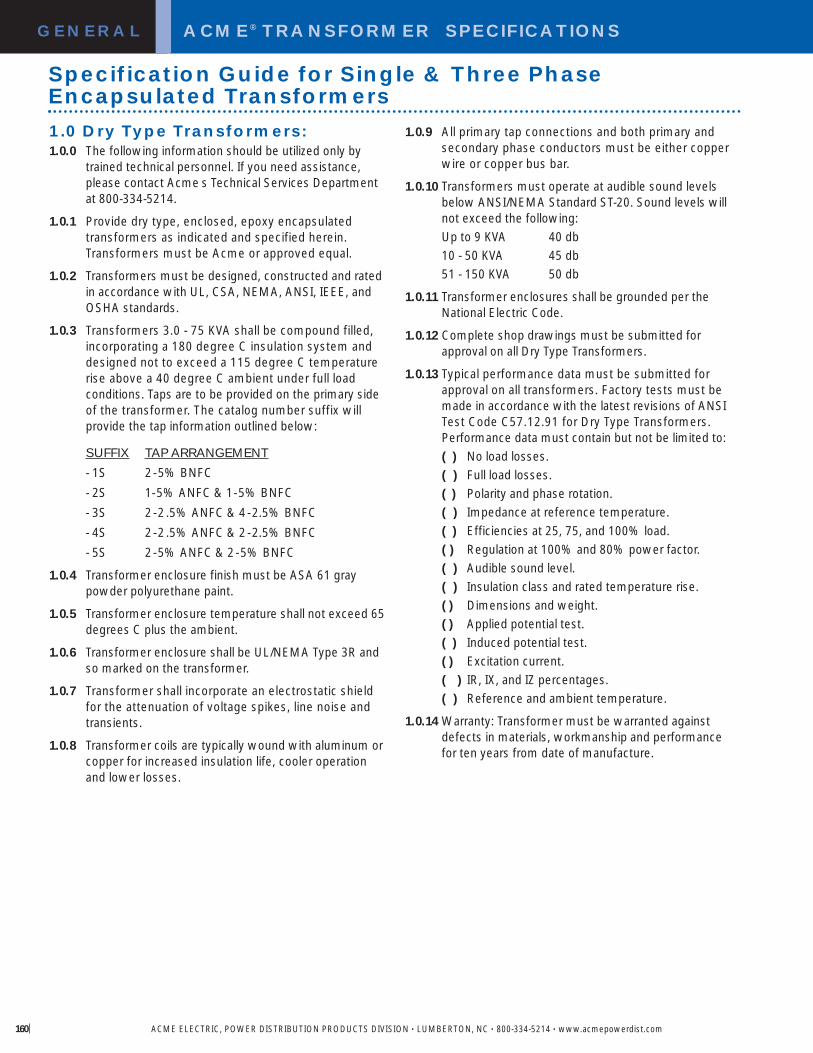
GENERAL ACME® TRANSFORMER SPECIFICATIONS
ACME ELECTRIC, POWER DISTRIBUTION PRODUCTS DIVISION • LUMBERTON, NC • 800-334-5214 • www.acmepowerdist.com160
1.0 Dry Type Transformers:1.0.0 The following information should be utilized only by
trained technical personnel. If you need assistance, please contact Acme s Technical Services Department at 800-334-5214.
1.0.1 Provide dry type, enclosed, epoxy encapsulated transformers as indicated and specified herein. Transformers must be Acme or approved equal.
1.0.2 Transformers must be designed, constructed and ratedin accordance with UL, CSA, NEMA, ANSI, IEEE, andOSHA standards.
1.0.3 Transformers 3.0 - 75 KVA shall be compound filled,incorporating a 180 degree C insulation system anddesigned not to exceed a 115 degree C temperaturerise above a 40 degree C ambient under full loadconditions. Taps are to be provided on the primary side of the transformer. The catalog number suffix willprovide the tap information outlined below:
SUFFIX TAP ARRANGEMENT
- 1S 2-5% BNFC- 2S 1-5% ANFC & 1-5% BNFC- 3S 2-2.5% ANFC & 4-2.5% BNFC- 4S 2-2.5% ANFC & 2-2.5% BNFC- 5S 2-5% ANFC & 2-5% BNFC
1.0.4 Transformer enclosure finish must be ASA 61 graypowder polyurethane paint.
1.0.5 Transformer enclosure temperature shall not exceed 65degrees C plus the ambient.
1.0.6 Transformer enclosure shall be UL/NEMA Type 3R andso marked on the transformer.
1.0.7 Transformer shall incorporate an electrostatic shieldfor the attenuation of voltage spikes, line noise andtransients.
1.0.8 Transformer coils are typically wound with aluminum orcopper for increased insulation life, cooler operationand lower losses.
1.0.9 All primary tap connections and both primary andsecondary phase conductors must be either copperwire or copper bus bar.
1.0.10 Transformers must operate at audible sound levelsbelow ANSI/NEMA Standard ST-20. Sound levels will not exceed the following:Up to 9 KVA 40 db10 - 50 KVA 45 db51 - 150 KVA 50 db
1.0.11 Transformer enclosures shall be grounded per theNational Electric Code.
1.0.12 Complete shop drawings must be submitted forapproval on all Dry Type Transformers.
1.0.13 Typical performance data must be submitted forapproval on all transformers. Factory tests must bemade in accordance with the latest revisions of ANSITest Code C57.12.91 for Dry Type Transformers.Performance data must contain but not be limited to:( ) No load losses.( ) Full load losses.( ) Polarity and phase rotation.( ) Impedance at reference temperature.( ) Efficiencies at 25, 75, and 100% load.( ) Regulation at 100% and 80% power factor.( ) Audible sound level.( ) Insulation class and rated temperature rise.( ) Dimensions and weight.( ) Applied potential test.( ) Induced potential test.( ) Excitation current.( ) IR, IX, and IZ percentages.( ) Reference and ambient temperature.
1.0.14 Warranty: Transformer must be warranted againstdefects in materials, workmanship and performancefor ten years from date of manufacture.
Specification Guide for Single & Three Phase Encapsulated Transformers

ACME ELECTRIC, POWER DISTRIBUTION PRODUCTS DIVISION • LUMBERTON, NC • 800-334-5214 • www.acmepowerdist.com 6
GENERAL ACME® TRANSFORMER™ SPECIFICATIONS
1.0 Dry Type Transformers:1.0.0 The following information should be utilized only by
trained technical personnel. If you need assistance, please contact Acme s Technical Services Department at 800-334-5214.
1.0.1 Provide dry type, enclosed, and ventilated transformersas indicated and specified herein. Transformers must beAcme or approved equal. Transformers must be UL listedfor non-sinusoidal current loads of a specified K Factor(UL Standard 1561), CSA certified and labeled as such.
1.0.2 For sizes 15 KVA and larger, low voltage dry transformerswill be ventilated type, incorporating a 220 degree Cinsulation system and designed not to exceed 150degree C temperature rise above a 40 degree Cambient under full load conditions. Taps will be providedon the primary side of the transformer. There will be 2, 2.5% taps above normal full capacity and 4, 2.5% tapsbelow normal full capacity.
A 1: 115 degree C rise Transformers shallincorporate a 220 degree C insulation system and bedesigned not to exceed 80 degree C temperature riseabove a 40 degree C ambient under full load conditions.In addition, the transformer shall have the ability to carrya continuous 15% overload without exceeding a 150degree C rise above ambient.
A 2: 80 degree C rise Transformers shallincorporate a 220 degree C insulation system and bedesigned not to exceed 80 degree C temperature riseabove a 40 degree C ambient under full load conditions.In addition, the transformer shall have the ability to carrya continuous 30% overload without exceeding a 150degree C rise above ambient.
1.0.3 Transformers shall incorporate an electrostatic shieldfor the attenuation of voltage spikes, line noise, andtransients.
1.0.4 Transformers must be designed to handle non-linearloads and the adverse effects of harmonics. Transformercoils will be wound with foil to minimize the heatingeffects caused by harmonic currents.
1.0.5 Transformers must be able to power non-linear loadswith a K-Factor as high as 20.
1.0.6 Transformers must operate at audible sound levelsbelow NEMA ST-20. Sound levels will not exceed thefollowing:30 - 50 KVA 45 db*51 - 150 KVA 50 db*151 - 300 KVA 55 db*301 - 500 KVA 60 db*
* Sound levels are based on transformers with a K-Factor of4 and a temperature rise of 150 degrees centigrade.
Enclosed, ventilated transformers must incorporatevibration dampening pads in their construction, located between the transformer core and coil assembly and the transformer case. External vibration dampening pads will not be used on enclosed, ventilated designs as they tend to increase audible noise. Transformers 15 KVA and larger shall be floor mounted on a concretepad. All connections to the transformer will be made by means of flexible metallic conduit.
1.0.7 Transformers shall incorporate a neutral conductorsized at 2 times rated phase current. Transformer cases shall be grounded per the National Electric Code.
1.0.8 Transformers shall be 60 Hz, 480 or 600 volts deltaprimary, 208Y/120 volt secondary. KVA rating asindicated. Contractor to provide all necessary lugs for all transformers. Transformer enclosures shall be Type 2 and UL-3R listed with the addition of a weather shield.
1.0.9 Complete shop drawings must be submitted forapproval on all dry type transformers.
1.0.10 Typical performance data must be submitted forapproval on all transformers. Factory tests must bemade in accordance with the latest revisions of ANSITest Code C57.12.91 for Dry Type Transformers.Performance data must contain but not be limited to:( ) No load losses.( ) Full load losses.( ) Polarity and phase rotation.( ) Impedance at reference temperature.( ) Efficiencies at 25, 75, 50 and 100% load.( ) Regulation at 100% and 80% power factor.( ) Audible sound level.( ) Insulation class and rated temperature rise.( ) Dimensions and weight.( ) Applied potential test.( ) Induced potential test.( ) Excitation current.( ) IR, IX, and IZ percentages.( ) Reference and ambient temperature.
1.0.11 Warranty: Transformers must be warranted againstdefects in materials, workmanship and performancefor ten years from date of manufacture.
Specification Guide for Non-Linear Load Isolation® Transformers
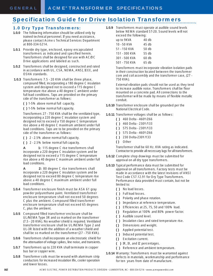
GENERAL ACME® TRANSFORMER SPECIFICATIONS
ACME ELECTRIC, POWER DISTRIBUTION PRODUCTS DIVISION • LUMBERTON, NC • 800-334-5214 • www.acmepowerdist.com162
1.0.9 Transformers must operate at audible sound levelsbelow NEMA standard ST-20. Sound levels will notexceed the following:up to 9KVA 40 db10 - 50 KVA 45 db51 - 150 KVA 50 db151 - 300 KVA 55 db301 - 500 KVA 60 db501 - 750 KVA 65 dbTransformers must incorporate vibration isolation padsin their construction located between the transformercore and coil assembly and the transformer case, (27 -750 KVA).External vibration pads should not be used as they tendto increase audible noise. Transformers shall be floormounted on a concrete pad. All connections to thetransformer will be made by means of flexible metallicconduit.
1.0.10 Transformer enclosure shall be grounded per theNational Electrical Code.
1.0.11 Transformer voltages shall be as follows:( ) 460 Delta - 460Y/266( ) 460 Delta - 230Y/133( ) 575 Delta - 230Y/133( ) 575 Delta - 460Y/266( ) 230 Delta-230Y/133( ) OtherTransformer shall be 60 Hz. KVA rating as indicated.Contractor to provide all necessary lugs for all transformers.
1.0.12 Complete shop drawings must be submitted forapproval on all dry type transformers.
1.0.13 Typical performance data must be submitted forapproval on all transformers. Factory tests must bemade in accordance with the latest revisions of ANSITest Code C57.12.91 for Dry Type Transformers.Performance data provided must contain, but not belimited to:( ) No load losses.( ) Full load losses.( ) Polarity and phase rotation.( ) Impedance at reference temperature.( ) Efficiencies at 25, 75, 50 and 100% load.( ) Regulation at 100% and 80% power factor.( ) Audible sound level.( ) Insulation class and rated temperature rise.( ) Dimensions and weight.( ) Applied potential test.( ) Induced potential test.( ) Excitation current.( ) IR, IX, and IZ percentages.( ) Reference and ambient temperature.
1.0.14 Warranty: Transformers must be warranted againstdefects in materials, workmanship and performancefor ten years from date of manufacture.
1.0 Dry Type Transformers:1.0.0 The following information should be utilized only by
trained technical personnel. If you need assistance, please contact Acme s Technical Services Department at 800-334-5214.
1.0.1 Provide dry type, enclosed, epoxy encapsulatedtransformers as indicated and specified herein. Transformers shall be designed for use with AC/DC Drive applications and labeled as such.
1.0.2 Transformers shall be designed, constructed and ratedin accordance with UL, CSA, NEMA, ANSI, IEEE, andOSHA standards.
1.0.3 Transformers 7.5 - 20 KVA shall be three phase, compound filled, incorporating a 180 degree C insulationsystem and designed not to exceed a 115 degree C temperature rise above a 40 degree C ambient under full load conditions. Taps are provided on the primary side of the transformer as follows:( ) 1-5% above normal full capacity.( ) 1-5% below normal full capacity.Transformers 27 - 750 KVA shall be the ventilated type,incorporating a 220 degree C insulation system anddesigned not to exceed a 150 degree C temperaturerise above a 40 degree C maximum ambient under fullload conditions. Taps are to be provided on the primaryside of the transformer as follows:( ) 2 - 2.5% above normal full capacity.( ) 2 - 2.5% below normal full capacity.A 1: 115 degree C rise transformers shallincorporate a 220 degree C insulation system and bedesigned not to exceed a 115 degree C temperaturerise above a 40 degree C maximum ambient under fullload conditions. A 2: 80 degree C rise transformers shallincorporate a 220 degree C insulation system and be designed not to exceed 80 degree C temperature rise above a 40 degree C maximum ambient under fullload conditions.
1.0.4 Transformer enclosure finish must be ASA 61 graypowder polyurethane paint. Ventilated transformerenclosure temperature shall not exceed 50 degreesC plus the ambient. Compound filled transformerenclosure temperature shall not exceed 65 degreesC, plus the ambient.
1.0.5 Compound filled transformer enclosure shall beUL/NEMA Type 3R and so marked on the transformer(7.5 - 20 KVA). No weather shield is required. Ventilatedtransformer enclosure shall be UL/NEMA Type 2 andUL-3R listed with the addition of a weather shield andshall be so marked on the transformer (27 - 750 KVA).
1.0.6 Transformers shall incorporate an electrostatic shield forthe attenuationof voltage spikes, line noise, and transients.
1.0.7 Transformers up to 220 KVA shall terminate in copperbus bar or copper wire.
1.0.8 Transformer coils must be wound with aluminum stripconductors for increased insulation life, cooler operationand lower losses.
Specification Guide for Drive Isolation Transformers
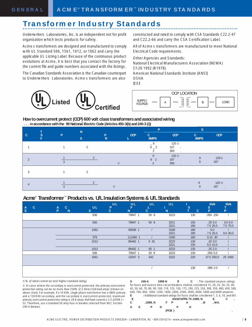
ACME® TRANSFORMER™ INDUSTRY STANDARDS
ACME ELECTRIC, POWER DISTRIBUTION PRODUCTS DIVISION • LUMBERTON, NC • 800-334-5214 • www.acmepowerdist.com 6
GENERAL
P ST N
C S P P OCP C OCP C OCPV S R L AMPS AMPS
9 125 �1 1 2 9 2 167 .
2 300 .
9 125 �2 1 2 9 2 167 . 9 125�
3 � 2 300 . 9 167 .
3 1 2
4 1 2 9 125 �3 � 9 167 .
ListedCertified
How to overcurrent protect (OCP) 600 volt class transformers and associated wiring. . . in accordance with the 99 National Electric Code (Articles 450-3(b) and 240-3 (i))
B LOADASUPPLYVOLTAGE
OCP LOCATION
�% of rated current (or next higher standard rating).� In cases where the secondary is overcurrent protected, the primary overcurrentprotection rating can be no more than 250% (2.5 times) full load amps (shown onabove chart). For example, if a 10 KVA, single phase transformer has a 480V primaryand a 120/240 secondary, and the secondary is overcurrent protected, maximumprimary overcurrent protection rating is 20.8 amps (full load current) x 2.5 (250%) =52. Therefore, use a standard 50 amp fuse or breaker selected from NEC Section240-6 (below).
Acme® Transformer™ Products vs. U/L Insulation Systems & U/L Standards
Transformer Industry StandardsUnderwriters Laboratories, Inc. is an independent not for profitorganization which tests products for safety.
Acme s transformers are designed and manufactured to complywith UL Standard 506, 1561, 1012, or 1062 and carry theapplicable UL Listing Label. Because of the continuous productevolutions at Acme, it is best that you contact the factory forthe current file and guide numbers associated with the listings.
The Canadian Standards Association is the Canadian counterpartto Underwriters Laboratories. Acme s transformers are also
constructed and rated to comply with CSA Standards C22.2-47and C22.2-66 and carry the CSA Certification Label.
All of Acme s transformers are manufactured to meet NationalElectrical Code requirements.
Other Agencies and Standards:National Electrical Manufacturers Association (NEMA) ST-20 1992 (R1978)American National Standards Institute (ANSI) OSHAIEEE
S 240-6 1999 N E C . The standard ampere ratingsfor fuses and inverse time circuit breakers shall be considered 15, 20, 25, 30, 35, 40,45, 50, 60, 70, 80, 90, 100, 110, 125, 150, 175, 200, 225, 250, 300, 350, 400, 450, 500,600, 700, 800, 1000, 1200, 1600, 2000, 2500, 3000, 4000, 5000 and 6000 amperes.E : Additional standard ratings for fuses shall be considered 1, 3, 6, 10, and 601.E ANSI/NFPA 70-1999, N E C ,
C ,1999, N F P A , B , MA.A E P D P D
(PCB ) .
U L U L U L U L I KVA KVAA C A C U L P F L I S S TS P N S C N C N T C P P
506 79947 1 50 8 3223 130 .050 .150 /
506 79947 1 50 8 3221 155 .25 5.0 3.0 6.03221 180 7.5 25.0 7.5 75.0
1062 56936 1 / 3180 180 5.0 /3221 180 7.5 25.0 9.0 30.0
379 111069 1 / 3180 180 0.10 .30 /1012 86492 1 6 81 3223 130 .25 3.0 /
3221 155 5.0 15.0 /1012 86492 1 60 1 3223 130 .25 2.0 /506 79947 1 50 8 3223 130 .050 5.0 /1561 12547 3 542 3222 220 37.5 250.0 25 1000
/ 130 .085 2.0 /

ALPHANUMERICAL CATALOG NUMBER INDEXGENERAL
ACME ELECTRIC, POWER DISTRIBUTION PRODUCTS DIVISION • LUMBERTON, NC • 800-334-5214 • www.acmepowerdist.com164
CATALOG NO. PAGE NO.100B12HA . . . . . . . . . . . . . . .138100B20HA . . . . . . . . . . . . . . .138100B24HA . . . . . . . . . . . . . . .138100B48HA . . . . . . . . . . . . . . .138100B7HA . . . . . . . . . . . . . . . .138200B12HA . . . . . . . . . . . . . . .138200B20HA . . . . . . . . . . . . . . .138200B24HA . . . . . . . . . . . . . . .138200B48HA . . . . . . . . . . . . . . .138200B7HA . . . . . . . . . . . . . . . .138500B24HA . . . . . . . . . . . . . . .138500B48HA . . . . . . . . . . . . . . .138750B24HA . . . . . . . . . . . . . . .138750B48HA . . . . . . . . . . . . . . .138AE01-0050 . . . . . . . . . . . . . . . .82AE01-0075 . . . . . . . . . . . . . . . .82AE01-0100 . . . . . . . . . . . . . . . .82AE01-0150 . . . . . . . . . . . . . . . .82AE01-0250 . . . . . . . . . . . . . . . .82AE01-0350 . . . . . . . . . . . . . . . .82AE01-0500 . . . . . . . . . . . . . . . .82AE01-0750 . . . . . . . . . . . . . . . .82AE02-0050 . . . . . . . . . . . . . . . .82AE02-0075 . . . . . . . . . . . . . . . .82AE02-0100 . . . . . . . . . . . . . . . .82AE02-0150 . . . . . . . . . . . . . . . .82AE02-0250 . . . . . . . . . . . . . . . .82AE02-0300 . . . . . . . . . . . . . . . .82AE02-0350 . . . . . . . . . . . . . . . .82AE02-0500 . . . . . . . . . . . . . . . .82AE02-0750 . . . . . . . . . . . . . . . .82AE03-0050 . . . . . . . . . . . . . . . .82AE03-0075 . . . . . . . . . . . . . . . .82AE03-0100 . . . . . . . . . . . . . . . .82AE03-0150 . . . . . . . . . . . . . . . .82AE03-0250 . . . . . . . . . . . . . . . .82AE03-0350 . . . . . . . . . . . . . . . .82AE03-0500 . . . . . . . . . . . . . . . .82AE03-0750 . . . . . . . . . . . . . . . .82AE06-0050 . . . . . . . . . . . . . . . .83AE06-0075 . . . . . . . . . . . . . . . .83AE06-0100 . . . . . . . . . . . . . . . .83AE06-0150 . . . . . . . . . . . . . . . .83AE06-0250 . . . . . . . . . . . . . . . .83AE06-0350 . . . . . . . . . . . . . . . .83AE06-0500 . . . . . . . . . . . . . . . .83AE06-0750 . . . . . . . . . . . . . . . .83AE07-0050 . . . . . . . . . . . . . . . .83AE07-0100 . . . . . . . . . . . . . . . .83AE07-0150 . . . . . . . . . . . . . . . .83AE07-0250 . . . . . . . . . . . . . . . .83AE07-0350 . . . . . . . . . . . . . . . .83AE07-0500 . . . . . . . . . . . . . . . .83AE07-0750 . . . . . . . . . . . . . . . .83AE12-0050 . . . . . . . . . . . . . . . .83AE12-0100 . . . . . . . . . . . . . . . .83AE12-0150 . . . . . . . . . . . . . . . .83AE12-0250 . . . . . . . . . . . . . . . .83
AE12-0350 . . . . . . . . . . . . . . . .83AE12-0500 . . . . . . . . . . . . . . . .83AE12-0750 . . . . . . . . . . . . . . . .83ALRB-002LWE . . . . . . . . . . . . .62ALRB-002TBC . . . . . . . . . . . . .60ALRB-003LWE . . . . . . . . . . . . .62ALRB-003TBC . . . . . . . . . . . . .60ALRB-004LWE . . . . . . . . . . . . .62ALRB-004TBC . . . . . . . . . . . . .60ALRB-006LWE . . . . . . . . . . . . .62ALRB-006TBC . . . . . . . . . . . . .60ALRB-008LWE . . . . . . . . . . . . .62ALRB-008TBC . . . . . . . . . . . . .60ALRB-012LWE . . . . . . . . . . . . .62ALRB-012TBC . . . . . . . . . . . . .60ALRB-016LWE . . . . . . . . . . . . .62ALRB-016TBC . . . . . . . . . . . . .60ALRB-025LWE . . . . . . . . . . . . .62ALRB-025TBC . . . . . . . . . . . . .60ALRB-027LWE . . . . . . . . . . . . .62ALRB-027TBC . . . . . . . . . . . . .60ALRB-035LWE . . . . . . . . . . . . .62ALRB-035TBC . . . . . . . . . . . . .60ALRB-045LWE . . . . . . . . . . . . .62ALRB-045TBC . . . . . . . . . . . . .60ALRB-055LWE . . . . . . . . . . . . .62ALRB-055TBC . . . . . . . . . . . . .60ALRB-080LWE . . . . . . . . . . . . .62ALRB-080TBC . . . . . . . . . . . . .60ALRB-110CBC . . . . . . . . . . . . .60ALRB-110LWE . . . . . . . . . . . . .62ALRB-130CBC . . . . . . . . . . . . .60ALRB-130LWE . . . . . . . . . . . . .62ALRB-160CBC . . . . . . . . . . . . .60ALRB-160LWE . . . . . . . . . . . . .62ALRB-200CBC . . . . . . . . . . . . .60ALRB-250CBC . . . . . . . . . . . . .60ALRB-300CBC . . . . . . . . . . . . .60ALRB-360CBC . . . . . . . . . . . . .60ALRB-420CBC . . . . . . . . . . . . .60ALRB-480CBC . . . . . . . . . . . . .60ALRB-600CBC . . . . . . . . . . . . .60ALRC-002LWE . . . . . . . . . . . . .62ALRC-002TBC . . . . . . . . . . . . .60ALRC-003LWE . . . . . . . . . . . . .62ALRC-003TBC . . . . . . . . . . . . .60ALRC-004LWE . . . . . . . . . . . . .62ALRC-004TBC . . . . . . . . . . . . .60ALRC-006LWE . . . . . . . . . . . . .62ALRC-006TBC . . . . . . . . . . . . .60ALRC-008LWE . . . . . . . . . . . . .62ALRC-008TBC . . . . . . . . . . . . .60ALRC-012LWE . . . . . . . . . . . . .62ALRC-012TBC . . . . . . . . . . . . .60ALRC-016LWE . . . . . . . . . . . . .62ALRC-016TBC . . . . . . . . . . . . .60ALRC-025LWE . . . . . . . . . . . . .62ALRC-025TBC . . . . . . . . . . . . .60
ALRC-027LWE . . . . . . . . . . . . .62ALRC-027TBC . . . . . . . . . . . . .60ALRC-035LWE . . . . . . . . . . . . .62ALRC-035TBC . . . . . . . . . . . . .60ALRC-045LWE . . . . . . . . . . . . .62ALRC-045TBC . . . . . . . . . . . . .60ALRC-055LWE . . . . . . . . . . . . .62ALRC-055TBC . . . . . . . . . . . . .60ALRC-080LWE . . . . . . . . . . . . .62ALRC-080TBC . . . . . . . . . . . . .60ALRC-110CBC . . . . . . . . . . . . .60ALRC-110LWE . . . . . . . . . . . . .62ALRC-130CBC . . . . . . . . . . . . .60ALRC-130LWE . . . . . . . . . . . . .62ALRC-160CBC . . . . . . . . . . . . .60ALRC-160LWE . . . . . . . . . . . . .62ALRC-200CBC . . . . . . . . . . . . .60ALRC-250CBC . . . . . . . . . . . . .60ALRC-300CBC . . . . . . . . . . . . .60ALRC-360CBC . . . . . . . . . . . . .60ALRC-420CBC . . . . . . . . . . . . .60ALRC-480CBC . . . . . . . . . . . . .60ALRC-600CBC . . . . . . . . . . . . .60CE01-0050 . . . . . . . . . . . . . . . .84CE01-0075 . . . . . . . . . . . . . . . .84CE01-0100 . . . . . . . . . . . . . . . .84CE01-0150 . . . . . . . . . . . . . . . .84CE01-0250 . . . . . . . . . . . . . . . .84CE01-0350 . . . . . . . . . . . . . . . .84CE01-0500 . . . . . . . . . . . . . . . .84CE01-0750 . . . . . . . . . . . . . . . .84CE02-0050 . . . . . . . . . . . . . . . .84CE02-0100 . . . . . . . . . . . . . . . .84CE02-0150 . . . . . . . . . . . . . . . .84CE02-0250 . . . . . . . . . . . . . . . .84CE02-0350 . . . . . . . . . . . . . . . .84CE02-0500 . . . . . . . . . . . . . . . .84CE02-0750 . . . . . . . . . . . . . . . .84CE03-0050 . . . . . . . . . . . . . . . .84CE03-0075 . . . . . . . . . . . . . . . .84CE03-0100 . . . . . . . . . . . . . . . .84CE03-0150 . . . . . . . . . . . . . . . .84CE03-0250 . . . . . . . . . . . . . . . .84CE03-0350 . . . . . . . . . . . . . . . .84CE03-0500 . . . . . . . . . . . . . . . .84CE03-0750 . . . . . . . . . . . . . . . .84CE04-0050 . . . . . . . . . . . . . . . .85CE04-0100 . . . . . . . . . . . . . . . .85CE04-0150 . . . . . . . . . . . . . . . .85CE04-0250 . . . . . . . . . . . . . . . .85CE04-0350 . . . . . . . . . . . . . . . .85CE04-0500 . . . . . . . . . . . . . . . .85CE04-0750 . . . . . . . . . . . . . . . .85CE05-0050 . . . . . . . . . . . . . . . .85CE05-0150 . . . . . . . . . . . . . . . .85CE05-0250 . . . . . . . . . . . . . . . .85CE05-0350 . . . . . . . . . . . . . . . .85CE05-0500 . . . . . . . . . . . . . . . .85
CE05-0750 . . . . . . . . . . . . . . . .85CE06-0050 . . . . . . . . . . . . . . . .85CE06-0075 . . . . . . . . . . . . . . . .85CE06-0100 . . . . . . . . . . . . . . . .85CE06-0150 . . . . . . . . . . . . . . . .85CE06-0250 . . . . . . . . . . . . . . . .85CE06-0300 . . . . . . . . . . . . . . . .85CE06-0350 . . . . . . . . . . . . . . . .85CE06-0500 . . . . . . . . . . . . . . . .85CE06-0750 . . . . . . . . . . . . . . . .85CMT-53312-4S . . . . . . . . . . . . .43CMT-53313-4S . . . . . . . . . . . . .43CMT-53314-4S . . . . . . . . . . . . .43CMT-53315-4S . . . . . . . . . . . . .43CMT-53316-4S . . . . . . . . . . . . .43CMT-53317-4S . . . . . . . . . . . . .43DR1-24013 . . . . . . . . . . . . . . .136DR1-24025 . . . . . . . . . . . . . . .136DR1-2405 . . . . . . . . . . . . . . . .136DR1-2410 . . . . . . . . . . . . . . . .136DR1-2420 . . . . . . . . . . . . . . . .136DR3-2405 . . . . . . . . . . . . . . . .136DR3-2410 . . . . . . . . . . . . . . . .136DR3-2420 . . . . . . . . . . . . . . . .136DR3-2440 . . . . . . . . . . . . . . . .136DRR-15GFI . . . . . . . . . . . . . . .137DRR-15 . . . . . . . . . . . . . . . . . .137DRR-20GFI . . . . . . . . . . . . . . .137DRR-20 . . . . . . . . . . . . . . . . . .137DTFA-011-2S . . . . . . . . . . . . . .57DTFA-0118-4S . . . . . . . . . . . . .57DTFA-014-2S . . . . . . . . . . . . . .57DTFA-0145-4S . . . . . . . . . . . . .57DTFA-0175-4S . . . . . . . . . . . . .57DTFA-020-2S . . . . . . . . . . . . . .57DTFA-0220-4S . . . . . . . . . . . . .57DTFA-027-4S . . . . . . . . . . . . . .57DTFA-034-4S . . . . . . . . . . . . . .57DTFA-040-4S . . . . . . . . . . . . . .57DTFA-051-4S . . . . . . . . . . . . . .57DTFA-063-4S . . . . . . . . . . . . . .57DTFA-075-4S . . . . . . . . . . . . . .57DTFA-093-4S . . . . . . . . . . . . . .57DTFA-7-2S . . . . . . . . . . . . . . . .57DTGA-00275-4S . . . . . . . . . . . .56DTGA-011-2S . . . . . . . . . . . . . .56DTGA-0118-4S . . . . . . . . . . . . .56DTGA-014-2S . . . . . . . . . . . . . .56DTGA-0145-4S . . . . . . . . . . . . .56DTGA-0175-4S . . . . . . . . . . . . .56DTGA-020-2S . . . . . . . . . . . . . .56DTGA-0220-4S . . . . . . . . . . . . .56DTGA-027-4S . . . . . . . . . . . . . .56DTGA-0330-4S . . . . . . . . . . . . .56DTGA-034-4S . . . . . . . . . . . . . .56DTGA-040-4S . . . . . . . . . . . . . .56DTGA-051-4S . . . . . . . . . . . . . .56DTGA-063-4S . . . . . . . . . . . . . .56
Alphanumerical Catalog Number IndexThis alphanumerical listing of catalog numbers has beenprepared to help you locate the appropriate page, when only
the catalog number is known. It is arranged in alphanumericalorder according to the first letter of the catalog number.
CATALOG NO. PAGE NO. CATALOG NO. PAGE NO. CATALOG NO. PAGE NO.

ALPHANUMERICAL CATALOG NUMBER INDEX
ACME ELECTRIC, POWER DISTRIBUTION PRODUCTS DIVISION • LUMBERTON, NC • 800-334-5214 • www.acmepowerdist.com 6
GENERAL
DTGA-075-4S . . . . . . . . . . . . . .56DTGA-093-4S . . . . . . . . . . . . . .56DTGA-440-4S . . . . . . . . . . . . . .56DTGA-550-4S . . . . . . . . . . . . . .56DTGA-660-4S . . . . . . . . . . . . . .56DTGA-7-2S . . . . . . . . . . . . . . . .56DTGB-00275-4S . . . . . . . . . . . .56DTGB-011-2S . . . . . . . . . . . . . .56DTGB-0118-4S . . . . . . . . . . . . .56DTGB-014-2S . . . . . . . . . . . . . .56DTGB-0145-4S . . . . . . . . . . . . .56DTGB-0175-4S . . . . . . . . . . . . .56DTGB-020-2S . . . . . . . . . . . . . .56DTGB-0220-4S . . . . . . . . . . . . .56DTGB-027-4S . . . . . . . . . . . . . .56DTGB-0330-4S . . . . . . . . . . . . .56DTGB-034-4S . . . . . . . . . . . . . .56DTGB-040-4S . . . . . . . . . . . . . .56DTGB-051-4S . . . . . . . . . . . . . .56DTGB-063-4S . . . . . . . . . . . . . .56DTGB-075-4S . . . . . . . . . . . . . .56DTGB-0880-4S . . . . . . . . . . . . .56DTGB-093-4S . . . . . . . . . . . . . .56DTGB-440-4S . . . . . . . . . . . . . .56DTGB-550-4S . . . . . . . . . . . . . .56DTGB-660-4S . . . . . . . . . . . . . .56DTGB-7-2S . . . . . . . . . . . . . . . .56DTGB-770-4S . . . . . . . . . . . . . .56DTHA-00275-4S . . . . . . . . . . . .56DTHA-011-2S . . . . . . . . . . . . . .56DTHA-0118-4S . . . . . . . . . . . . .56DTHA-014-2S . . . . . . . . . . . . . .56DTHA-0145-4S . . . . . . . . . . . . .56DTHA-0175-4S . . . . . . . . . . . . .56DTHA-020-2S . . . . . . . . . . . . . .56DTHA-0220-4S . . . . . . . . . . . . .56DTHA-027-4S . . . . . . . . . . . . . .56DTHA-0330-4S . . . . . . . . . . . . .56DTHA-034-4S . . . . . . . . . . . . . .56DTHA-040-4S . . . . . . . . . . . . . .56DTHA-051-4S . . . . . . . . . . . . . .56DTHA-063-4S . . . . . . . . . . . . . .56DTHA-075-4S . . . . . . . . . . . . . .56DTHA-093-4S . . . . . . . . . . . . . .56DTHA-440-4S . . . . . . . . . . . . . .56DTHA-550-4S . . . . . . . . . . . . . .56DTHA-660-4S . . . . . . . . . . . . . .56DTHA-7-2S . . . . . . . . . . . . . . . .56DTHB-00275-4S . . . . . . . . . . . .56DTHB-011-2S . . . . . . . . . . . . . .56DTHB-0118-4S . . . . . . . . . . . . .56DTHB-014-2S . . . . . . . . . . . . . .56DTHB-0145-4S . . . . . . . . . . . . .56DTHB-0175-4S . . . . . . . . . . . . .56DTHB-020-2S . . . . . . . . . . . . . .56DTHB-0220-4S . . . . . . . . . . . . .56DTHB-027-4S . . . . . . . . . . . . . .56DTHB-0330-4S . . . . . . . . . . . . .56DTHB-034-4S . . . . . . . . . . . . . .56DTHB-040-4S . . . . . . . . . . . . . .56DTHB-051-4S . . . . . . . . . . . . . .56DTHB-063-4S . . . . . . . . . . . . . .56DTHB-0660-4S . . . . . . . . . . . . .56
DTHB-075-4S . . . . . . . . . . . . . .56DTHB-093-4S . . . . . . . . . . . . . .56DTHB-440-4S . . . . . . . . . . . . . .56DTHB-550-4S . . . . . . . . . . . . . .56DTHB-7-2S . . . . . . . . . . . . . . . .56FS-1-1000 . . . . . . . . . . . . . . . . .89FS-1-100 . . . . . . . . . . . . . . . . . .89FS-1-150 . . . . . . . . . . . . . . . . . .89FS-1-250 . . . . . . . . . . . . . . . . . .89FS-1-350 . . . . . . . . . . . . . . . . . .89FS-1-500 . . . . . . . . . . . . . . . . . .89FS-1-50 . . . . . . . . . . . . . . . . . . .89FS-1-750 . . . . . . . . . . . . . . . . . .89FS-1-75 . . . . . . . . . . . . . . . . . . .89FS-2-1000 . . . . . . . . . . . . . . . . .89FS-2-100 . . . . . . . . . . . . . . . . . .89FS-2-1500 . . . . . . . . . . . . . . . . .89FS-2-150 . . . . . . . . . . . . . . . . . .89FS-2-2000 . . . . . . . . . . . . . . . . .89FS-2-250 . . . . . . . . . . . . . . . . . .89FS-2-3000 . . . . . . . . . . . . . . . . .89FS-2-300 . . . . . . . . . . . . . . . . . .89FS-2-350 . . . . . . . . . . . . . . . . . .89FS-2-500 . . . . . . . . . . . . . . . . . .89FS-2-50 . . . . . . . . . . . . . . . . . . .89FS-2-750 . . . . . . . . . . . . . . . . . .89FS-2-75 . . . . . . . . . . . . . . . . . . .89FS-3-1000 . . . . . . . . . . . . . . . . .89FS-3-1500 . . . . . . . . . . . . . . . . .89FS-3-150 . . . . . . . . . . . . . . . . . .89FS-3-2000 . . . . . . . . . . . . . . . . .89FS-3-250 . . . . . . . . . . . . . . . . . .89FS-3-3000 . . . . . . . . . . . . . . . . .89FS-3-350 . . . . . . . . . . . . . . . . . .89FS-3-500 . . . . . . . . . . . . . . . . . .89FS-3-50 . . . . . . . . . . . . . . . . . . .89FS-3-750 . . . . . . . . . . . . . . . . . .89GP12-10000-S . . . . . . . . . . . . .22GP12-1000-S . . . . . . . . . . . . . .22GP12-15000-S . . . . . . . . . . . . .22GP12-250-S . . . . . . . . . . . . . . .22GP12-3000-S . . . . . . . . . . . . . .22GP12-5000-S . . . . . . . . . . . . . .22GP12-500-S . . . . . . . . . . . . . . .22LN3-53312-3S . . . . . . . . . . . . .24LN3-53313-3S . . . . . . . . . . . . .24LN3-53314-3S . . . . . . . . . . . . .24LN3-53315-3S . . . . . . . . . . . . .24LN3-53316-3S . . . . . . . . . . . . .24LN3-53317-3S . . . . . . . . . . . . .24LN3-53342-3S . . . . . . . . . . . . .25LN3-53343-3S . . . . . . . . . . . . .25LN3-53344-3S . . . . . . . . . . . . .25LN3-53345-3S . . . . . . . . . . . . .25LN3-53346-3S . . . . . . . . . . . . .25LN3-53347-3S . . . . . . . . . . . . .25LUG-1 . . . . . . . . . . . . . . . . . . .158LUG-2 . . . . . . . . . . . . . . . . . . .158LUG-3 . . . . . . . . . . . . . . . . . . .158LUG-4 . . . . . . . . . . . . . . . . . . .158MC-1-53314-1S . . . . . . . . . . . .39MC-1-53314-8S . . . . . . . . . . . .39MC-2-53317-1S . . . . . . . . . . . .39
MC-2-53317-3S . . . . . . . . . . . .40MC-2-53317-8S . . . . . . . . . . . .39MC-2-53318-1S . . . . . . . . . . . .39MC-2-53318-3S . . . . . . . . . . . .40MC-2-53318-8S . . . . . . . . . . . .39MC-53312-1S . . . . . . . . . . . . . .39MC-53312-3S . . . . . . . . . . . . . .40MC-53312-8S . . . . . . . . . . . . . .39MC-53313-1S . . . . . . . . . . . . . .39MC-53313-3S . . . . . . . . . . . . . .40MC-53313-8S . . . . . . . . . . . . . .39MC-53314-3S . . . . . . . . . . . . . .40MC-53315-1S . . . . . . . . . . . . . .39MC-53315-3S . . . . . . . . . . . . . .40MC-53315-8S . . . . . . . . . . . . . .39MC-53316-1S . . . . . . . . . . . . . .39MC-53316-3S . . . . . . . . . . . . . .40MC-53316-8S . . . . . . . . . . . . . .39ME-2-53312-1S . . . . . . . . . . . .38ME-2-53312-8S . . . . . . . . . . . .38ME-2-53313-1S . . . . . . . . . . . .38ME-2-53313-8S . . . . . . . . . . . .38ME-2-53314-1S . . . . . . . . . . . .38ME-2-53314-8S . . . . . . . . . . . .38ME-2-53315-1S . . . . . . . . . . . .38ME-2-53315-8S . . . . . . . . . . . .38ME-2-53316-1S . . . . . . . . . . . .38ME-2-53316-8S . . . . . . . . . . . .38ME-2-53318-1S . . . . . . . . . . . .38ME-2-53318-8S . . . . . . . . . . . .38ME-2-53319-1S . . . . . . . . . . . .38ME-2-53319-8S . . . . . . . . . . . .38ME-2-53321-1S . . . . . . . . . . . .38ME-2-53321-8S . . . . . . . . . . . .38ME-3-53317-1S . . . . . . . . . . . .38ME-3-53317-8S . . . . . . . . . . . .38NS10-01253316-8S . . . . . . . . .48NC10-0253311-8S . . . . . . . . . .51NC10-0253312-1S . . . . . . . . . .50NC10-0253312-3S . . . . . . . . . .49NC10-0253312-8S . . . . . . . . . .51NC10-0253313-1S . . . . . . . . . .50NC10-0253313-3S . . . . . . . . . .49NC10-0253313-8S . . . . . . . . . .51NC10-0253314-1S . . . . . . . . . .50NC10-0253314-3S . . . . . . . . . .49NC10-0253314-8S . . . . . . . . . .51NC10-0253315-1S . . . . . . . . . .50NC10-0253315-3S . . . . . . . . . .49NC10-0253315-8S . . . . . . . . . .51NC10-0253316-3S . . . . . . . . . .49NC10-0253317-8S . . . . . . . . . .51NC10-0253318-1S . . . . . . . . . .50NC10-0253318-3S . . . . . . . . . .49NC10-0253318-8S . . . . . . . . . .51NC10-1253316-1S . . . . . . . . . .50NC10-1253316-8S . . . . . . . . . .51NC10-1253317-1S . . . . . . . . . .50NC10-1253317-3S . . . . . . . . . .49NC25-0053311-3S . . . . . . . . . .49NC25-0053311-8S . . . . . . . . . .51NC25-0053312-1S . . . . . . . . . .50NC25-0053312-3S . . . . . . . . . .49
NC25-0053312-8S . . . . . . . . . .51NC25-0053313-1S . . . . . . . . . .50NC25-0053313-3S . . . . . . . . . .49NC25-0053313-8S . . . . . . . . . .51NC25-0053314-1S . . . . . . . . . .50NC25-0053314-3S . . . . . . . . . .49NC25-0053314-8S . . . . . . . . . .51NC25-0053315-1S . . . . . . . . . .50NC25-0053315-3S . . . . . . . . . .49NC25-0053315-8S . . . . . . . . . .51NC25-0053316-1S . . . . . . . . . .50NC25-0053316-3S . . . . . . . . . .49NC25-0053318-8S . . . . . . . . . .51NC25-0053319-1S . . . . . . . . . .50NC25-0053319-3S . . . . . . . . . .49NC25-1053316-8S . . . . . . . . . .51NC25-1053317-1S . . . . . . . . . .50NC25-1053317-3S . . . . . . . . . .49NC25-1053317-8S . . . . . . . . . .51NC25-1053318-1S . . . . . . . . . .50NC25-1053318-3S . . . . . . . . . .49NC75-0153311-1S . . . . . . . . . .50NC75-0153311-3S . . . . . . . . . .49NC75-0153311-8S . . . . . . . . . .51NC75-0153312-1S . . . . . . . . . .50NC75-0153312-3S . . . . . . . . . .49NC75-0153312-8S . . . . . . . . . .51NC75-0153313-1S . . . . . . . . . .50NC75-0153313-3S . . . . . . . . . .49NC75-0153313-8S . . . . . . . . . .51NC75-0153314-1S . . . . . . . . . .50NC75-0153314-3S . . . . . . . . . .49NC75-0153314-8S . . . . . . . . . .51NC75-0153315-1S . . . . . . . . . .50NC75-0153315-3S . . . . . . . . . .49NC75-0153315-8S . . . . . . . . . .51NC75-0153316-3S . . . . . . . . . .49NC75-0153318-1S . . . . . . . . . .50NC75-0153318-8S . . . . . . . . . .51NC75-0153319-3S . . . . . . . . . .49NC75-1153316-1S . . . . . . . . . .50NC75-1153316-8S . . . . . . . . . .51NC75-1153317-1S . . . . . . . . . .50NC75-1153317-3S . . . . . . . . . .49NC75-1153317-8S . . . . . . . . . .51NC75-1153318-3S . . . . . . . . . .49NS10-0253311-1S . . . . . . . . . .47NS10-0253311-3S . . . . . . . . . .46NS10-0253312-1S . . . . . . . . . .47NS10-0253312-3S . . . . . . . . . .46NS10-0253312-8S . . . . . . . . . .48NS10-0253313-1S . . . . . . . . . .47NS10-0253313-3S . . . . . . . . . .46NS10-0253313-8S . . . . . . . . . .48NS10-0253314-1S . . . . . . . . . .47NS10-0253314-3S . . . . . . . . . .46NS10-0253314-8S . . . . . . . . . .48NS10-0253315-1S . . . . . . . . . .47NS10-0253315-3S . . . . . . . . . .46NS10-0253316-3S . . . . . . . . . .46NS10-0253317-1S . . . . . . . . . .47NS10-0253317-3S . . . . . . . . . .46NS10-0253317-8S . . . . . . . . . .48
CATALOG NO. PAGE NO. CATALOG NO. PAGE NO. CATALOG NO. PAGE NO. CATALOG NO. PAGE NO.

ALPHANUMERICAL CATALOG NUMBER INDEXGENERAL
ACME ELECTRIC, POWER DISTRIBUTION PRODUCTS DIVISION • LUMBERTON, NC • 800-334-5214 • www.acmepowerdist.com166
NS10-0253318-1S . . . . . . . . . .47NS10-0253318-8S . . . . . . . . . .48NS10-0253319-3S . . . . . . . . . .46NS10-1253316-1S . . . . . . . . . .47NS10-1253315-8S . . . . . . . . . .48NS10-253318-3S . . . . . . . . . . .46NS25-0053311-1S . . . . . . . . . .47NS25-0053311-3S . . . . . . . . . .46NS25-0053311-8S . . . . . . . . . .48NS25-0053312-1S . . . . . . . . . .47NS25-0053312-3S . . . . . . . . . .46NS25-0053312-8S . . . . . . . . . .48NS25-0053313-1S . . . . . . . . . .47NS25-0053313-3S . . . . . . . . . .46NS25-0053313-8S . . . . . . . . . .48NS25-0053314-1S . . . . . . . . . .47NS25-0053314-3S . . . . . . . . . .46NS25-0053314-8S . . . . . . . . . .48NS25-0053315-1S . . . . . . . . . .47NS25-0053315-3S . . . . . . . . . .46NS25-0053315-8S . . . . . . . . . .48NS25-0053316-1S . . . . . . . . . .47NS25-0053316-3S . . . . . . . . . .46NS25-0053317-8S . . . . . . . . . .48NS25-0053318-1S . . . . . . . . . .47NS25-0053318-3S . . . . . . . . . .46NS25-0053318-8S . . . . . . . . . .48NS25-0053319-1S . . . . . . . . . .47NS25-0053319-3S . . . . . . . . . .46NS25-0053319-8S . . . . . . . . . .48NS25-1053316-8S . . . . . . . . . .48NS25-1053317-1S . . . . . . . . . .47NS25-1053317-3S . . . . . . . . . .46NS75-0153311-1S . . . . . . . . . .47NS75-0153311-3S . . . . . . . . . .46NS75-0153311-8S . . . . . . . . . .48NS75-0153312-1S . . . . . . . . . .47NS75-0153312-3S . . . . . . . . . .46NS75-0153312-8S . . . . . . . . . .48NS75-0153313-1S . . . . . . . . . .47NS75-0153313-3S . . . . . . . . . .46NS75-0153313-8S . . . . . . . . . .48NS75-0153314-1S . . . . . . . . . .47NS75-0153314-3S . . . . . . . . . .46NS75-0153314-8S . . . . . . . . . .48NS75-0153315-1S . . . . . . . . . .47NS75-0153315-3S . . . . . . . . . .46NS75-0153315-8S . . . . . . . . . .48NS75-0153316-1S . . . . . . . . . .47NS75-0153316-3S . . . . . . . . . .46NS75-0153316-8S . . . . . . . . . .48NS75-0153317-1S . . . . . . . . . .47NS75-0153317-8S . . . . . . . . . .48NS75-0153318-1S . . . . . . . . . .47NS75-0153318-3S . . . . . . . . . .46NS75-0153318-8S . . . . . . . . . .48NS75-0153319-3S . . . . . . . . . .46NS75-0153319-8S . . . . . . . . . .48NS75-0179271-4S . . . . . . . . . .48NS75-0179272-4S . . . . . . . . . .48NS75-0179273-4S . . . . . . . . . .48NS75-0179274-4S . . . . . . . . . .48NS75-0179275-4S . . . . . . . . . .48
NS75-0179276-4S . . . . . . . . . .48NS75-1153317-3S . . . . . . . . . .46PL-112600 . . . . . . . . . . . . . . . .76PL-112601 . . . . . . . . . . . . . . . .76PL-112602 . . . . . . . . . . . . . . . .76PL-112603 . . . . . . . . . . . . . . . .76PL-112700 . . . . . . . . . . . . . . . .76PL-112701 . . . . . . . . . . . . . . . .76PL-112702 . . . . . . . . . . . . . . . .76PL-112703 . . . . . . . . . . . . . . . .76PL-112704 . . . . . . . . . . . . . . . .76PL-112705 . . . . . . . . . . . . . . . .76PL-112706 . . . . . . . . . . . . . . . .76PL-112707 . . . . . . . . . . . . . . . .76PL-79900 . . . . . . . . . . . . . . . .157PL-79905 . . . . . . . . . . . . . . . . .90PL-79906 . . . . . . . . . . . . . . . . .90PL-79907 . . . . . . . . . . . . . . . . .90PL-79908 . . . . . . . . . . . . . . . . .90PL-79911 . . . . . . . . . . . . . . . .157PL-79912 . . . . . . . . . . . . . . . .157PL-79920 . . . . . . . . . . . . . . . . .87PL-79921 . . . . . . . . . . . . . . . . .87PL-79922 . . . . . . . . . . . . . . . . .87PL-79923 . . . . . . . . . . . . . . . . .87PL-79924 . . . . . . . . . . . . . .76, 87PL-79925 . . . . . . . . . . . . . . . . .87PL-79926 . . . . . . . . . . . . . . . . .87PL-79927 . . . . . . . . . . . . . . . . .87PL-79928 . . . . . . . . . . . . . .76, 87PL-79929 . . . . . . . . . . . . . .76, 87PL-79930 . . . . . . . . . . . . . .76, 87PL-79931 . . . . . . . . . . . . . .76, 87PLC-85000 . . . . . . . . . . . . . . .131PLC-85001 . . . . . . . . . . . . . . .131PLC-85002 . . . . . . . . . . . . . . .131PLC-85003 . . . . . . . . . . . . . . .131PLC-85004 . . . . . . . . . . . . . . .131PT-06-1150005-LS . . . . . . . . .122PT-06-1150005-SS . . . . . . . . .122PT-06-1150007-LS . . . . . . . . .122PT-06-1150007-SS . . . . . . . . .122PT-06-1150010-LS . . . . . . . . .122PT-06-1150010-SS . . . . . . . . .122PT-06-1150015-LS . . . . . . . . .122PT-06-1150015-SS . . . . . . . . .122PT-06-1150025-LS . . . . . . . . .122PT-06-1150025-SS . . . . . . . . .122PTBA-3150009-LS . . . . . . . . .123PTBA-3150009-SS . . . . . . . . .123PTBA-3150015-LS . . . . . . . . .123PTBA-3150015-SS . . . . . . . . .123PTBA-3150022-LS . . . . . . . . .123PTBA-3150022-SS . . . . . . . . .123PTBA-3150030-LS . . . . . . . . .123PTBA-3150030-SS . . . . . . . . .123SA-1-701319 . . . . . . . . . . . . .158SA-1-701320 . . . . . . . . . . . . .158SA-1-701321 . . . . . . . . . . . . .158SA-2-701319 . . . . . . . . . . . . .158SA-2-701320 . . . . . . . . . . . . .158SA-2-701321 . . . . . . . . . . . . .158SA-3-701319 . . . . . . . . . . . . .158
SA-3-701320 . . . . . . . . . . . . .158SA-3-701321 . . . . . . . . . . . . .158SA-4-701319 . . . . . . . . . . . . .158SA-4-701320 . . . . . . . . . . . . .158SA-4-701321 . . . . . . . . . . . . .158SA-6-701319 . . . . . . . . . . . . .158SA-7-701321 . . . . . . . . . . . . .158SPS-12012 . . . . . . . . . . . . . . .140SPS-1202428 . . . . . . . . . . . . .140SPS-152428 . . . . . . . . . . . . . .140SPS-3012 . . . . . . . . . . . . . . . .140SPS-302428 . . . . . . . . . . . . . .140SPS-6012 . . . . . . . . . . . . . . . .140SPS-602428 . . . . . . . . . . . . . .140SPWS-1217 . . . . . . . . . . . . . .142SPWS-2412 . . . . . . . . . . . . . .142SPWS-2424 . . . . . . . . . . . . . .142SPWS-2436 . . . . . . . . . . . . . .142SPWS-2448 . . . . . . . . . . . . . .142SPWS-2472 . . . . . . . . . . . . . .142SPWS-53-OV . . . . . . . . . . . . .142T-100012-S . . . . . . . . . . . . . . . .98T-100024-S . . . . . . . . . . . . . . . .98T-10012-S . . . . . . . . . . . . . . . . .98T-10024-S . . . . . . . . . . . . . . . . .98T-1-11683 . . . .101, 110, 113, 116T-1-11684 . . . .101, 110, 113, 116T-1-11685 . . . .101, 110, 113, 116T-1-11686 . . . .101, 110, 113, 116T-1-11687 . . . .101, 110, 113, 116T-1-13073 . . . . . . . .111, 114, 116T-1-13074 . . . . . . . .111, 114, 116T-1-13075 . . . . . . . .111, 114, 116T-1-13076 . . . . . . . .111, 114, 116T-1-13077 . . . . . . . .111, 114, 116T-13102-3S . . . . . . . . . . . . . . . .26T-13103-3S . . . . . . . . . . . . . . . .26T-13104-3S . . . . . . . . . . . . . . . .26T-13142-3S . . . . . . . . . . . . . . . .27T-13143-3S . . . . . . . . . . . . . . . .27T-13144-3S . . . . . . . . . . . . . . . .27T-1-37920 . . . . . . . .112, 115, 116T-1-37921 . . . . . . . .112, 115, 116T-1-37922 . . . . . . . .112, 115, 116T-1-37923 . . . . . . . .112, 115, 116T-1-37924 . . . . . . . .112, 115, 116T-150024-S . . . . . . . . . . . . . . . .98T-15012-S . . . . . . . . . . . . . . . . .98T-15024-S . . . . . . . . . . . . . . . . .98T-1-53004 . . . . . . . . . . . . . . . . .17T-1-53005 . . . . . . . . . . . . . . . . .17T-1-53006 . . . . . . . . . . . . . . . . .17T-1-53022-1S . . . . . . . . . . . . . .37T-1-53023-3S . . . . . . . . . . . . . .17T-1-53104 . . . . . . . . . . . . . . . . .19T-1-53105 . . . . . . . . . . . . . . . . .19T-1-53106 . . . . . . . . . . . . . . . . .19T-1-53122-1S . . . . . . . . . . . . . .37T-1-53122-8S . . . . . . . . . . . . . .37T-1-53123-3S . . . . . . . . . . . . . .19T-1-53322-2S . . . . . . . . . . . . . .23T-1-53349-3S . . . . . . . . . . . . . .25T-1-53929 . . . . . . . . . . . . . . . . .79
T-1-53930 . . . . . . . . . . . . . . . . .79T-1-53931 . . . . . . . . . . . . . . . . .79T-1-60800 . . . . . . . . . . . . . . . .128T-1-60801 . . . . . . . . . . . . . . . .128T-1-60802 . . . . . . . . . . . . . . . .128T-1-60830 . . . . . . . . . . . . . . . .128T-1-60831 . . . . . . . . . . . . . . . .128T-1-60832 . . . . . . . . . . . . . . . .128T-1-60833 . . . . . . . . . . . . . . . .128T-1-60834 . . . . . . . . . . . . . . . .128T-1-60835 . . . . . . . . . . . . . . . .128T-1-69430 . . . . . . . . . . . . . . . .131T-1-69431 . . . . . . . . . . . . . . . .131T-1-69432 . . . . . . . . . . . . . . . .131T-1-69433 . . . . . . . . . . . . . . . .131T-1-69434 . . . . . . . . . . . . . . . .131T-1-69435 . . . . . . . . . . . . . . . .131T-1-69436 . . . . . . . . . . . . . . . .131T-1-69437 . . . . . . . . . . . . . . . .131T-1-69438 . . . . . . . . . . . . . . . .131T-1-69439 . . . . . . . . . . . . . . . .131T-1-79101-SL . . . . . . . . . . . . . .99T-1-79101-SR . . . . . . . . . . . . . .99T-1-79105-SL . . . . . . . . . . . . . .99T-1-79105-SR . . . . . . . . . . . . . .99T-1-79203-SL . . . . . . . . . . . . . .99T-1-79203-SR . . . . . . . . . . . . . .99T-1-79600-S . . . . . . . . . . . . . .100T-1-79603-S . . . . . . . . . . . . . .100T-1-79604-S . . . . . . . . . . . . . .100T-1-79605-S . . . . . . . . . . . . . .100T-1-79608-S . . . . . . . . . . . . . .100T-1-79609-S . . . . . . . . . . . . . .100T-1-79615-S . . . . . . . . . . . . . .100T-1-79618-S . . . . . . . . . . . . . .100T-1-79619-S . . . . . . . . . . . . . .100T-1-79620-S . . . . . . . . . . . . . .100T-1-79621-S . . . . . . . . . . . . . .100T-1-79622-S . . . . . . . . . . . . . .100T-1-79623-S . . . . . . . . . . . . . .100T-1-79624-S . . . . . . . . . . . . . .100T-1-79625-S . . . . . . . . . . . . . .100T-1-79629-S . . . . . . . . . . . . . .100T-1-79630-S . . . . . . . . . . . . . .100T-1-79631-S . . . . . . . . . . . . . .100T-1-81047 . . . .101, 110, 113, 116T-1-81048 . . . .101, 110, 113, 116T-1-81049 . . . .101, 110, 113, 116T-1-81050 . . . .101, 110, 113, 116T-1-81051 . . . .101, 110, 113, 116T-1-81052 . . . .101, 110, 113, 116T-1-81054 . . . . . . . .111, 114, 116T-1-81055 . . . . . . . .111, 114, 116T-1-81056 . . . . . . . .111, 114, 116T-1-81057 . . . . . . . .111, 114, 116T-1-81058 . . . . . . . .111, 114, 116T-1-81059 . . . . . . . .111, 114, 116T-1-81061 . . . . . . . .112, 115, 116T-1-81062 . . . . . . . .112, 115, 116T-1-81063 . . . . . . . .112, 115, 116T-1-81064 . . . . . . . .112, 115, 116T-1-81065 . . . . . . . .112, 115, 116T-1-81066 . . . . . . . .112, 115, 116
CATALOG NO. PAGE NO. CATALOG NO. PAGE NO. CATALOG NO. PAGE NO. CATALOG NO. PAGE NO.

ALPHANUMERICAL CATALOG NUMBER INDEX
ACME ELECTRIC, POWER DISTRIBUTION PRODUCTS DIVISION • LUMBERTON, NC • 800-334-5214 • www.acmepowerdist.com 6
GENERAL
T-1-81217 . . . . . . . . . . . . . . . . .79T-1-81219 . . . . . . . . . . . . . . . . .79T-1-81220 . . . . . . . . . . . . . . . . .79T-1-81221 . . . . . . . . . . . . . . . . .79T-1-81223 . . . . . . . . . . . . . . . . .79T-2-11688 . . . .101, 110, 113, 116T-2-11689 . . . .101, 110, 113, 116T-2-13078 . . . . . . . .111, 114, 116T-2-13079 . . . . . . . .111, 114, 116T-2-43570 . . . . . . . .112, 115, 116T-2-43571 . . . . . . . .112, 115, 116T-25012-S . . . . . . . . . . . . . . . . .98T-25024-S . . . . . . . . . . . . . . . . .98T-2-52703-1 . . . . . . . . . . . . . . .29T-2-52705-1 . . . . . . . . . . . . . . .29T-2-52707-1 . . . . . . . . . . . . . . .29T-2-53007-S . . . . . . . . . . . . . . .17T-2-53007-SS . . . . . . . . . . . . . .17T-2-53008-S . . . . . . . . . . . . . . .17T-2-53008-SS . . . . . . . . . . . . . .17T-2-53009-S . . . . . . . . . . . . . . .17T-2-53009-SS . . . . . . . . . . . . . .17T-2-53010-S . . . . . . . . . . . . . . .17T-2-53010-SS . . . . . . . . . . . . . .17T-2-53011-S . . . . . . . . . . . . . . .17T-2-53011-SS . . . . . . . . . . . . . .17T-2-53012-S . . . . . . . . . . . . . . .17T-2-53012-SS . . . . . . . . . . . . . .17T-2-53013-4S . . . . . . . . . . . . . .17T-2-53013-S . . . . . . . . . . . . . . .17T-2-53013-SS . . . . . . . . . . . . . .17T-2-53014-4S . . . . . . . . . . . . . .17T-2-53014-S . . . . . . . . . . . . . . .17T-2-53014-SS . . . . . . . . . . . . . .17T-2-53019-1S . . . . . . . . . . . . . .37T-2-53019-3S . . . . . . . . . . . . . .17T-2-53019-8S . . . . . . . . . . . . . .37T-2-53020-1S . . . . . . . . . . . . . .37T-2-53020-3S . . . . . . . . . . . . . .17T-2-53020-8S . . . . . . . . . . . . . .37T-2-53021-3S . . . . . . . . . . . . . .17T-2-53023-1S . . . . . . . . . . . . . .37T-2-53023-8S . . . . . . . . . . . . . .37T-2-53024-3S . . . . . . . . . . . . . .17T-2-53060 . . . . . . . . . . . . . . . . .20T-2-53061 . . . . . . . . . . . . . . . . .20T-2-53062 . . . . . . . . . . . . . . . . .20T-2-53063 . . . . . . . . . . . . . . . . .20T-2-53064 . . . . . . . . . . . . . . . . .20T-2-53065 . . . . . . . . . . . . . . . . .20T-2-53066 . . . . . . . . . . . . . . . . .20T-2-53067 . . . . . . . . . . . . . . . . .20T-2-53107-S . . . . . . . . . . . . . . .19T-2-53108-S . . . . . . . . . . . . . . .19T-2-53109-S . . . . . . . . . . . . . . .19T-2-53110-S . . . . . . . . . . . . . . .19T-2-53111-S . . . . . . . . . . . . . . .19T-2-53112-S . . . . . . . . . . . . . . .19T-2-53113-1S . . . . . . . . . . . . . .19T-2-53114-1S . . . . . . . . . . . . . .19T-2-53119-1S . . . . . . . . . . . . . .37T-2-53119-3S . . . . . . . . . . . . . .19T-2-53119-8S . . . . . . . . . . . . . .37
T-2-53120-1S . . . . . . . . . . . . . .37T-2-53120-3S . . . . . . . . . . . . . .19T-2-53120-8S . . . . . . . . . . . . . .37T-2-53121-3S . . . . . . . . . . . . . .19T-2-53140-1S . . . . . . . . . . . . . .19T-2-53141-1S . . . . . . . . . . . . . .19T-2-53142-1S . . . . . . . . . . . . . .19T-2-53143-1S . . . . . . . . . . . . . .19T-2-53144-1S . . . . . . . . . . . . . .19T-2-53170-1S . . . . . . . . . . . . . .20T-2-53171-1S . . . . . . . . . . . . . .20T-2-53172-1S . . . . . . . . . . . . . .20T-2-53173-1S . . . . . . . . . . . . . .20T-2-53174-1S . . . . . . . . . . . . . .20T-2-53319-3S . . . . . . . . . . . . . .23T-2-53321-3S . . . . . . . . . . . . . .23T-2-53350-3S . . . . . . . . . . . . . .25T-2-53366-4S . . . . . . . . . . . . . .22T-2-53367-4S . . . . . . . . . . . . . .22T-2-53515-3S . . . . . . . . . . . . . .17T-2-53515-SS . . . . . . . . . . . . . .17T-2-53516-3S . . . . . . . . . . . . . .17T-2-53516-SS . . . . . . . . . . . . . .17T-2-53517-3S . . . . . . . . . . . . . .17T-2-53517-SS . . . . . . . . . . . . . .17T-2-53518-3S . . . . . . . . . . . . . .17T-2-53518-SS . . . . . . . . . . . . . .17T-2-53615-1S . . . . . . . . . . . . . .19T-2-53616-1S . . . . . . . . . . . . . .19T-2-53617-1S . . . . . . . . . . . . . .19T-2-53618-1S . . . . . . . . . . . . . .19T-2-53645-1S . . . . . . . . . . . . . .19T-2-53646-1S . . . . . . . . . . . . . .19T-2-53647-1S . . . . . . . . . . . . . .19T-2-53648-1S . . . . . . . . . . . . . .19T-2-53649-1S . . . . . . . . . . . . . .19T-2-53650-3S . . . . . . . . . . . . . .19T-2-53651-3S . . . . . . . . . . . . . .19T-2-53675-1S . . . . . . . . . . . . . .20T-2-53676-1S . . . . . . . . . . . . . .20T-2-53677-1S . . . . . . . . . . . . . .20T-2-53678-1S . . . . . . . . . . . . . .20T-2-79272-4S . . . . . . . . . . . . . .27T-2-79273-4S . . . . . . . . . . . . . .27T-2-79274-4S . . . . . . . . . . . . . .27T-2-79275-4S . . . . . . . . . . . . . .27T-2-79276-4S . . . . . . . . . . . . . .27T-2-79277-4S . . . . . . . . . . . . . .27T-2-79368-4S . . . . . . . . . . . . . .22T-2-79369-4S . . . . . . . . . . . . . .22T-2-79370-4S . . . . . . . . . . . . . .22T-2-79371-4S . . . . . . . . . . . . . .22T-2-79372-4S . . . . . . . . . . . . . .22T-2-79373-4S . . . . . . . . . . . . . .22T-2-79376-2S . . . . . . . . . . . . . .22T-2-79524-3S . . . . . . . . . . . . . .27T-2-79556-3S . . . . . . . . . . . . . .28T-2-79694-4S . . . . . . . . . . . . . .27T-2-79695-4S . . . . . . . . . . . . . .27T-2-79696-4S . . . . . . . . . . . . . .27T-2-79697-4S . . . . . . . . . . . . . .27T-2-79698-4S . . . . . . . . . . . . . .27T-2-79740-S . . . . . . . . . . . . . . .20
T-2-79741-S . . . . . . . . . . . . . . .20T-2-79742-S . . . . . . . . . . . . . . .20T-2-79743-S . . . . . . . . . . . . . . .20T-2-79744-S . . . . . . . . . . . . . . .20T-2-79745-S . . . . . . . . . . . . . . .20T-2-79746-S . . . . . . . . . . . . . . .20T-2-79747-S . . . . . . . . . . . . . . .20T-2-79748-S . . . . . . . . . . . . . . .20T-2A-3500030-3S . . . . . . . . . . .26T-2A-3500045-3S . . . . . . . . . . .26T-2A-3500112-3S . . . . . . . . . . .26T-2A-3500150-3S . . . . . . . . . . .26T-2A-3500225-3S . . . . . . . . . . .26T-2A-52712-1 . . . . . . . . . . . . . .29T-2A-52713-1 . . . . . . . . . . . . . .29T-2A-52715-1 . . . . . . . . . . . . . .29T-2A-52717-1 . . . . . . . . . . . . . .29T-2A-52718-1 . . . . . . . . . . . . . .29T-2A-52719-1 . . . . . . . . . . . . . .29T-2A-53021-1S . . . . . . . . . . . . .37T-2A-53021-8S . . . . . . . . . . . . .37T-2A-53022-3S . . . . . . . . . . . . .17T-2A-53121-1S . . . . . . . . . . . . .37T-2A-53121-8S . . . . . . . . . . . . .37T-2A-53122-3S . . . . . . . . . . . . .19T-2A-53308-1S . . . . . . . . . . . . .23T-2A-53308-SS . . . . . . . . . . . . .24T-2A-53309-1S . . . . . . . . . . . . .23T-2A-53309-SS . . . . . . . . . . . . .24T-2A-53310-1S . . . . . . . . . . . . .23T-2A-53310-SS . . . . . . . . . . . . .24T-2A-53315-3S . . . . . . . . . . . . .23T-2A-53328-1S . . . . . . . . . . . . .25T-2A-53329-1S . . . . . . . . . . . . .25T-2A-53340-1S . . . . . . . . . . . . .25T-2A-53345-3S . . . . . . . . . . . . .25T-2A-53360-1S . . . . . . . . . . . . .22T-2A-53365-4S . . . . . . . . . . . . .22T-2A-79084-S . . . . . . . . . . . . . .29T-2A-79085-S . . . . . . . . . . . . . .29T-2A-79087-S . . . . . . . . . . . . . .29T-2A-79088-S . . . . . . . . . . . . . .29T-2A-79268-1S . . . . . . . . . . . . .27T-2A-79269-1S . . . . . . . . . . . . .27T-2A-79270-1S . . . . . . . . . . . . .27T-2A-79330-1S . . . . . . . . . . . . .26T-2A-79331-1S . . . . . . . . . . . . .26T-2A-79332-1S . . . . . . . . . . . . .26T-2A-79516-1S . . . . . . . . . . . . .27T-2A-79517-1S . . . . . . . . . . . . .27T-2A-79518-1S . . . . . . . . . . . . .27T-2A-79520-3S . . . . . . . . . . . . .27T-2A-79521-3S . . . . . . . . . . . . .27T-2A-79523-3S . . . . . . . . . . . . .27T-2A-79552-3S . . . . . . . . . . . . .28T-2A-79553-3S . . . . . . . . . . . . .28T-2A-79554-3S . . . . . . . . . . . . .28T-2A-79555-3S . . . . . . . . . . . . .28T-2A-79708-4S . . . . . . . . . . . . .28T-2A-79709-4S . . . . . . . . . . . . .28T-2A-79710-4S . . . . . . . . . . . . .28T-2A-79715-3S . . . . . . . . . . . . .28T-3-3500015-3S . . . . . . . . . . . .26
T-3-3500075-3S . . . . . . . . . . . .26T-3-3500300-3S . . . . . . . . . . . .26T-3-52710-1 . . . . . . . . . . . . . . .29T-3-53040-S . . . . . . . . . . . . . . .18T-3-53041-S . . . . . . . . . . . . . . .18T-3-53042-S . . . . . . . . . . . . . . .18T-3-53043-S . . . . . . . . . . . . . . .18T-3-53044-S . . . . . . . . . . . . . . .18T-3-53311-1S . . . . . . . . . . . . . .23T-3-53311-SS . . . . . . . . . . . . . .24T-3-53312-3S . . . . . . . . . . . . . .23T-3-53313-3S . . . . . . . . . . . . . .23T-3-53314-3S . . . . . . . . . . . . . .23T-3-53316-3S . . . . . . . . . . . . . .23T-3-53317-3S . . . . . . . . . . . . . .23T-3-53318-3S . . . . . . . . . . . . . .23T-3-53341-1S . . . . . . . . . . . . . .25T-3-53342-3S . . . . . . . . . . . . . .25T-3-53343-3S . . . . . . . . . . . . . .25T-3-53344-3S . . . . . . . . . . . . . .25T-3-53346-3S . . . . . . . . . . . . . .25T-3-53347-3S . . . . . . . . . . . . . .25T-3-53348-3S . . . . . . . . . . . . . .25T-3-53361-1S . . . . . . . . . . . . . .22T-3-53362-4S . . . . . . . . . . . . . .22T-3-53363-4S . . . . . . . . . . . . . .22T-3-53364-4S . . . . . . . . . . . . . .22T-3-53393-3S . . . . . . . . . . . . . .23T-3-53394-3S . . . . . . . . . . . . . .23T-3-53403-3S . . . . . . . . . . . . . .23T-3-53545-S . . . . . . . . . . . . . . .18T-3-53546-S . . . . . . . . . . . . . . .18T-3-53547-S . . . . . . . . . . . . . . .18T-3-53548-S . . . . . . . . . . . . . . .18T-3-79068-1S . . . . . . . . . . . . . .29T-3-79069-3S . . . . . . . . . . . . . .29T-3-79070-3S . . . . . . . . . . . . . .29T-3-79071-3S . . . . . . . . . . . . . .29T-3-79083-S . . . . . . . . . . . . . . .29T-3-79271-1S . . . . . . . . . . . . . .27T-3-79312-3S . . . . . . . . . . . . . .24T-3-79312-SS . . . . . . . . . . . . . .24T-3-79313-3S . . . . . . . . . . . . . .24T-3-79313-SS . . . . . . . . . . . . . .24T-3-79314-3S . . . . . . . . . . . . . .24T-3-79314-SS . . . . . . . . . . . . . .24T-3-79333-1S . . . . . . . . . . . . . .26T-3-79334-3S . . . . . . . . . . . . . .26T-3-79335-3S . . . . . . . . . . . . . .26T-3-79336-3S . . . . . . . . . . . . . .26T-3-79367-1S . . . . . . . . . . . . . .22T-3-79374-4S . . . . . . . . . . . . . .22T-3-79519-1S . . . . . . . . . . . . . .27T-3-79522-3S . . . . . . . . . . . . . .27T-3-79551-1S . . . . . . . . . . . . . .28T-3-79557-3S . . . . . . . . . . . . . .28T-3-79693-1S . . . . . . . . . . . . . .27T-3-79711-4S . . . . . . . . . . . . . .28T-3-79712-3S . . . . . . . . . . . . . .28T-3-79713-3S . . . . . . . . . . . . . .28T-3-79714-3S . . . . . . . . . . . . . .28T-50012-S . . . . . . . . . . . . . . . . .98T-50024-S . . . . . . . . . . . . . . . . .98
CATALOG NO. PAGE NO. CATALOG NO. PAGE NO. CATALOG NO. PAGE NO. CATALOG NO. PAGE NO.

T-75012-S . . . . . . . . . . . . . . . . .98T-75024-S . . . . . . . . . . . . . . . . .98T-79101-SL . . . . . . . . . . . . . . . .99T-79101-SR . . . . . . . . . . . . . . . .99T-79105-SL . . . . . . . . . . . . . . . .99T-79105-SR . . . . . . . . . . . . . . . .99T-79203-SL . . . . . . . . . . . . . . . .99T-79203-SR . . . . . . . . . . . . . . . .99T-79804-3S . . . . . . . . . . . . . . . .23T-79805-3S . . . . . . . . . . . . . . . .23T-79806-3S . . . . . . . . . . . . . . . .23T-79807-3 . . . . . . . . . . . . . . . . .23T-79844-3S . . . . . . . . . . . . . . . .25T-79845-3S . . . . . . . . . . . . . . . .25T-79846-3S . . . . . . . . . . . . . . . .25T-79847-3 . . . . . . . . . . . . . . . . .25TA-2-53929 . . . . . . . . . . . . . . . .72TA-2-53930 . . . . . . . . . . . . . . . .72TA-2-53931 . . . . . . . . . . . . . . . .72TA-2-54525 . . . . . . . . . . . . . . . .74TA-2-54535 . . . . . . . . . . . . . . . .74TA-2-54536 . . . . . . . . . . . . . . . .74TA-2-54537 . . . . . . . . . . . . . . . .74TA-2-54538 . . . . . . . . . . . . . . . .74TA-2-54539 . . . . . . . . . . . . . . . .74TA-2-81008 . . . . . . . . . . . . . . . .72TA-2-81197 . . . . . . . . . . . . . . . .74TA-2-81202 . . . . . . . . . . . . . . . .74TA-2-81203 . . . . . . . . . . . . . . . .74TA-2-81205 . . . . . . . . . . . . . . . .74TA-2-81218 . . . . . . . . . . . . . . . .72TA-2-81219 . . . . . . . . . . . . . . . .72TA-2-81220 . . . . . . . . . . . . . . . .72TA-2-81221 . . . . . . . . . . . . . . . .72TA-2-81240 . . . . . . . . . . . . . . . .74TA-2-81241 . . . . . . . . . . . . . . . .74TA-83221 . . . . . . . . . . . . . . . . .76TA-83222 . . . . . . . . . . . . . . . . .76TA-83223 . . . . . . . . . . . . . . . . .76TA-83224 . . . . . . . . . . . . . . . . .76TA-83300 . . . . . . . . . . . . . . . . .75TA-83301 . . . . . . . . . . . . . . . . .75TA-83302 . . . . . . . . . . . . . . . . .75TA-83303 . . . . . . . . . . . . . . . . .75TA-83304 . . . . . . . . . . . . . . . . .75TA-83305 . . . . . . . . . . . . . . . . .75TA-83306 . . . . . . . . . . . . . . . . .75TA-83310 . . . . . . . . . . . . . . . . .76TA-83311 . . . . . . . . . . . . . . . . .76TA-83312 . . . . . . . . . . . . . . . . .76TA-83313 . . . . . . . . . . . . . . . . .76TA-83314 . . . . . . . . . . . . . . . . .76TA-83315 . . . . . . . . . . . . . . . . .76TA-83316 . . . . . . . . . . . . . . . . .76TB-2-69300 . . . . . . . . . . . . . . . .75TB-2-69301 . . . . . . . . . . . . . . . .75TB-2-69302 . . . . . . . . . . . . . . . .75TB-2-69303 . . . . . . . . . . . . . . . .75TB-2-69304 . . . . . . . . . . . . . . . .75TB-2-69305 . . . . . . . . . . . . . . . .75TB-2-69306 . . . . . . . . . . . . . . . .75TB-2-69307 . . . . . . . . . . . . . . . .75TB-32403 . . . . . . . . . . . . . . . . .74
TB-32404 . . . . . . . . . . . . . . . . .74TB-32405 . . . . . . . . . . . . . . . . .74TB-32406 . . . . . . . . . . . . . . . . .74TB-32669 . . . . . . . . . . . . . . . . .74TB-54523 . . . . . . . . . . . . . . . . .74TB-54524 . . . . . . . . . . . . . . . . .74TB-81000 . . . . . . . . . . . . . . . . .72TB-81001 . . . . . . . . . . . . . . . . .72TB-81002 . . . . . . . . . . . . . . . . .72TB-81003 . . . . . . . . . . . . . . . . .72TB-81004 . . . . . . . . . . . . . . . . .72TB-81005 . . . . . . . . . . . . . . . . .72TB-81006 . . . . . . . . . . . . . . . . .72TB-81007 . . . . . . . . . . . . . . . . .72TB-81009 . . . . . . . . . . . . . . . . .72TB-81020 . . . . . . . . . . . . . . . . .72TB-81141 . . . . . . . . . . . . . . . . .71TB-81142 . . . . . . . . . . . . . . . . .71TB-81143 . . . . . . . . . . . . . . . . .71TB-81144 . . . . . . . . . . . . . . . . .71TB-81146 . . . . . . . . . . . . . . . . .71TB-81148 . . . . . . . . . . . . . . . . .71TB-81149 . . . . . . . . . . . . . . . . .71TB-81150 . . . . . . . . . . . . . . . . .71TB-81151 . . . . . . . . . . . . . . . . .71TB-81200 . . . . . . . . . . . . . . . . .71TB-81201 . . . . . . . . . . . . . . . . .71TB-81210 . . . . . . . . . . . . . . . . .71TB-81211 . . . . . . . . . . . . . . . . .71TB-81212 . . . . . . . . . . . . . . . . .71TB-81213 . . . . . . . . . . . . . . . . .71TB-81214 . . . . . . . . . . . . . . . . .72TB-81215 . . . . . . . . . . . . . . . . .72TB-81216 . . . . . . . . . . . . . . . . .72TB-81217 . . . . . . . . . . . . . . . . .72TB-81301 . . . . . . . . . . . . . . . . .73TB-81302 . . . . . . . . . . . . . . . . .73TB-81303 . . . . . . . . . . . . . . . . .73TB-81304 . . . . . . . . . . . . . . . . .73TB-81305 . . . . . . . . . . . . . . . . .73TB-81306 . . . . . . . . . . . . . . . . .73TB-81307 . . . . . . . . . . . . . . . . .73TB-81308 . . . . . . . . . . . . . . . . .73TB-81309 . . . . . . . . . . . . . . . . .73TB-81321 . . . . . . . . . . . . . . . . .73TB-81322 . . . . . . . . . . . . . . . . .73TB-81323 . . . . . . . . . . . . . . . . .73TB-81324 . . . . . . . . . . . . . . . . .73TB-81325 . . . . . . . . . . . . . . . . .73TB-81326 . . . . . . . . . . . . . . . . .73TB-81327 . . . . . . . . . . . . . . . . .73TB-81328 . . . . . . . . . . . . . . . . .73TB-81329 . . . . . . . . . . . . . . . . .73TB-83210 . . . . . . . . . . . . . . . . .76TB-83212 . . . . . . . . . . . . . . . . .76TB-83213 . . . . . . . . . . . . . . . . .76TB-83215 . . . . . . . . . . . . . . . . .76TB-83218 . . . . . . . . . . . . . . . . .76TB-83219 . . . . . . . . . . . . . . . . .76TB-83220 . . . . . . . . . . . . . . . . .76TC-1-53318-3S . . . . . . . . . . . . .23TC-53019-3S . . . . . . . . . . . . . .18TC-53020-3S . . . . . . . . . . . . . .18
TC-53021-3S . . . . . . . . . . . . . .18TC-53022-3S . . . . . . . . . . . . . .18TC-53311-1S . . . . . . . . . . . . . .23TC-53312-3S . . . . . . . . . . . . . .23TC-53313-3S . . . . . . . . . . . . . .23TC-53314-3S . . . . . . . . . . . . . .23TC-53315-3S . . . . . . . . . . . . . .23TC-53316-3S . . . . . . . . . . . . . .23TC-53317-3S . . . . . . . . . . . . . .23TC-53319-3S . . . . . . . . . . . . . .23TC-53515-3S . . . . . . . . . . . . . .18TC-53516-3S . . . . . . . . . . . . . .18TC-53517-3S . . . . . . . . . . . . . .18TC-53518-3S . . . . . . . . . . . . . .18TE-1-53022-3S . . . . . . . . . . . . .18TE-2-53019-3S . . . . . . . . . . . . .18TE-2-53020-3S . . . . . . . . . . . . .18TE-2-53312-3S . . . . . . . . . . . . .24TE-2-53313-3S . . . . . . . . . . . . .24TE-2-53314-3S . . . . . . . . . . . . .24TE-2-53343-3S . . . . . . . . . . . . .26TE-2-53344-3S . . . . . . . . . . . . .26TE2A-53021-3S . . . . . . . . . . . .18TE-3-53315-3S . . . . . . . . . . . . .24TE-3-53342-3S . . . . . . . . . . . . .26TE-3-53345-3S . . . . . . . . . . . . .26TF-2-17437-S . . . . . . . . . . . . . .21TF-2-17439-S . . . . . . . . . . . . . .21TF-220100-5S . . . . . . . . . . . . . .28TF-22010-5S . . . . . . . . . . . . . . .28TF-22015-5S . . . . . . . . . . . . . . .28TF-220200-5S . . . . . . . . . . . . . .28TF-220250-5S . . . . . . . . . . . . . .28TF-22025-5S . . . . . . . . . . . . . . .28TF-220300-5S . . . . . . . . . . . . . .28TF-220500-5S . . . . . . . . . . . . . .28TF-22050-5S . . . . . . . . . . . . . . .28TF-2-49873-S . . . . . . . . . . . . . .21TF-2-52520-S . . . . . . . . . . . . . .21TF-2-52794-S . . . . . . . . . . . . . .21TF-2-52795-S . . . . . . . . . . . . . .21TF-2-52796-S . . . . . . . . . . . . . .21TF-2-52797-S . . . . . . . . . . . . . .21TF-2-69218-S . . . . . . . . . . . . . .21TF-2-69219-S . . . . . . . . . . . . . .21TF-2-69220-S . . . . . . . . . . . . . .21TF-2-79260-S . . . . . . . . . . . . . .21TF-2-79261-S . . . . . . . . . . . . . .21TF-2-79262-S . . . . . . . . . . . . . .21TF-2-79263-S . . . . . . . . . . . . . .21TF-2-79264-S . . . . . . . . . . . . . .21TF-2-79265-S . . . . . . . . . . . . . .21TF-2-79266-S . . . . . . . . . . . . . .21TF-2-79267-S . . . . . . . . . . . . . .21TF-2-79300-S . . . . . . . . . . . . . .21TF-2-79301-S . . . . . . . . . . . . . .21TF-2-79302-S . . . . . . . . . . . . . .21TF-2-79303-S . . . . . . . . . . . . . .21TF-2-79304-S . . . . . . . . . . . . . .21TF-2A-69221-S . . . . . . . . . . . . .21TLV-100012-S . . . . . . . . . . . . . .98TLV-100024-S . . . . . . . . . . . . . .98TLV-10012-SC . . . . . . . . . . . . . .98
TLV-10012-S . . . . . . . . . . . . . . .98TLV-10024-SC . . . . . . . . . . . . . .98TLV-10024-S . . . . . . . . . . . . . . .98TLV-150024-S . . . . . . . . . . . . . .98TLV-15012-SC . . . . . . . . . . . . . .98TLV-15012-S . . . . . . . . . . . . . . .98TLV-15024-SC . . . . . . . . . . . . . .98TLV-15024-S . . . . . . . . . . . . . . .98TLV-25012-SC . . . . . . . . . . . . . .98TLV-25012-S . . . . . . . . . . . . . . .98TLV-25024-SC . . . . . . . . . . . . . .98TLV-25024-S . . . . . . . . . . . . . . .98TLV-50012-SC . . . . . . . . . . . . . .98TLV-50012-S . . . . . . . . . . . . . . .98TLV-50024-SC . . . . . . . . . . . . . .98TLV-50024-S . . . . . . . . . . . . . . .98TLV-75012-S . . . . . . . . . . . . . . .98TLV-75024-S . . . . . . . . . . . . . . .98TLVA-30012-SC . . . . . . . . . . . .97TLVA-30024-SC . . . . . . . . . . . .97TLVA-60012-SC . . . . . . . . . . . .97TLVA-60024-SC . . . . . . . . . . . .97TP1-53342-3S . . . . . . . . . . . . . .39TP1-53343-3S . . . . . . . . . . . . . .39TP1-53344-3S . . . . . . . . . . . . . .39TP1-53345-3S . . . . . . . . . . . . . .39TP1-53346-3S . . . . . . . . . . . . . .39TP1-53347-3S . . . . . . . . . . . . . .39TP1-53348-3S . . . . . . . . . . . . . .39TP-53019-3S . . . . . . . . . . . . . . .37TP-53020-3S . . . . . . . . . . . . . . .37TP-53021-3S . . . . . . . . . . . . . . .37TP-53022-3S . . . . . . . . . . . . . . .37TP-53312-3S . . . . . . . . . . . . . . .38TP-53313-3S . . . . . . . . . . . . . . .38TP-53314-3S . . . . . . . . . . . . . . .38TP-53315-3S . . . . . . . . . . . . . . .38TP-53316-3S . . . . . . . . . . . . . . .38TP-53317-3S . . . . . . . . . . . . . . .38TP-53318-3S . . . . . . . . . . . . . . .38TP-53319-3S . . . . . . . . . . . . . . .38TP-53321-3S . . . . . . . . . . . . . . .38TP-53322-3S . . . . . . . . . . . . . . .38TTBD-3500500-3S . . . . . . . . . .26WS-A-1 . . . . . . . . . . . . . . . . . .158WS-A-2 . . . . . . . . . . . . . . . . . .158WS-A-3 . . . . . . . . . . . . . . . . . .158WS-A-4 . . . . . . . . . . . . . . . . . .158WS-A-53 . . . . . . . . . . . . . . . . .158WS-A-58 . . . . . . . . . . . . . . . . .158WS-A-5 . . . . . . . . . . . . . . . . . .158WS-A-60 . . . . . . . . . . . . . . . . .158WS-A-6 . . . . . . . . . . . . . . . . . .158WS-A-8 . . . . . . . . . . . . . . . . . .158WS-B-1 . . . . . . . . . . . . . . . . . .158WS-B-2 . . . . . . . . . . . . . . . . . .158WS-B-3 . . . . . . . . . . . . . . . . . .158WS-B-4 . . . . . . . . . . . . . . . . . .158WS-B-5 . . . . . . . . . . . . . . . . . .158
CATALOG NO. PAGE NO. CATALOG NO. PAGE NO. CATALOG NO. PAGE NO. CATALOG NO. PAGE NO.
GENERAL ALPHANUMERICAL CATALOG NUMBER INDEX
ACME ELECTRIC, POWER DISTRIBUTION PRODUCTS DIVISION • LUMBERTON, NC • 800-334-5214 • www.acmepowerdist.com6

ACME ELECTRIC 10-YEAR LIMITED* WARRANTYAcme Electric Corporation (Acme) warrants to the original purchaser to correct by repair, replacement or refundof original purchase price, at Acme s option, products manufactured and sold by its Power Distribution ProductsDivision, that may fail in service within the applicable period as set forth below, from the date of manufactureprovided however, that conditions of operation have been normal at all times, and that the equipment has not beensubjected to abnormal stress from such causes as incorrect primary voltage or frequency, improper ventilationor improper use. This warranty is made on the condition that prompt notice of defect is given to Acme in writingwithin the warranty period,and that Acme s inspection reveals to its satisfaction that the original purchaser s claimis valid under the terms of this warranty. Acme s obligation under this warranty, which is in lieu of all otherwarranties, express or implied, including the implied warranty of fitness for a particular purpose and merchantability,is limited to replacing or repairing defective products or parts, free of charge, provided they are returned to thefactory, or refund of original purchase price, at Acme s option. However, purchased components (except for timersand photocells used in low voltage lighting power supplies) including but not limited to capacitors, circuit breakers,terminal blocks, batteries, fuses and tubes shall not be covered under this warranty. Repairs or replacementdeliveries shall not interrupt or prolong the term of this warranty. Acme will not be liable for any special, indirect,consequential or incidental damages, including, without limitation, from loss of use, data, function or profitsderiving out of or in connection with the use or performance of the product and shall have no liability for paymentof any other damages whether in an action of contract, strict liability or tort. The remedy provided herein statesAcme Electric Corporation s entire liability and buyer s sole and exclusive remedy here under. Rights mayvary in certain states.
*Warranty Period:Standard Catalog Transformers 10-year limited; Low Voltage Lighting Power Supplies, transformer 10-yearlimited, photocell and timer 3 years; Standard Power™ DC Power Supplies 2 years; True-Power® PowerLine Conditioners, 10-year limited; Custom products 1 year.
Acme®Transformers™ are Shielded for Cleaner Power – Free!Shielding is a FREE standardfeature. Acme transformers have built-in noise and surge protection providedby internal electrostatic shielding. It s a standard feature on Acme general purpose dry-type transformers.
Acme transformers provide cleanpower. They provide noise and surgeprotection for entire feeder and branchcircuits, plus every connected load. And,they establish a separately derived circuitand provide a solid single point ground
all essential for cleaner power. InstallAcme transformers, and take the mostfundamental and cost effective steptoward cleaner power.
The more you use, the cleaneryour system. The Acme shield constantly works to trap, knockdownand shunt potentially damaging noiseand voltage spikes to ground at anaverage reduction ratio of 100:1. Themore Acme shielded transformers youuse on the feeder and branch circuits,the cleaner your system becomes.Use two Acme transformers on thesame feeder and branch circuits, andget 10,000:1 reduction.
With Acme you get all the extra benefitsof cleaner power, absolutely FREE!
Shieldedfor cleaner
power™

4815 West Fifth Street
Lumberton, NC 28358
(910) 738-1121 Inside NC
(800) 334-5214 Outside NC
(910) 739-0024 Fax
. .
Printed in USAATD-101-1001Revised-02/ 06