section 3 deck systems section 3 - deck · pdf filesection 3 deck systems 3-1 r9/12 section 3...
TRANSCRIPT
SECTION 3 DECK SYSTEMS
3-1 R9/12
SECTION 3 - DECK SYSTEMS (Revised 9/12)
3.0 – THRUWAY DECK SLAB AND OVERLAY POLICY
The following Thruway deck slab and overlay policy is to be applied to all Thruway mainline,
Thruway ramp and non-Thruway overhead bridges built (new), replaced or rehabilitated by a
NYSTA construction contract. The following policy can only be deviated from when a request to do
so is made by the DSD, a Thruway Division Director, or a local municipality, and the request is
approved by the Assistant Chief Engineer (ACE).
3.0.1 – NEW AND REPLACEMENT BRIDGES
The Thruway Authority allows the design and construction of both monolithic cast-in-place concrete
bridge decks and two-course bridge decks; but a monolithic cast-in-place concrete bridge deck is the
Thruway’s preferred, and most commonly used, new deck design. However, designers are
encouraged to thoroughly investigate other methods early in a project’s scoping phase, a few
alternate methods are presented in Subsection 3.2.
All new or replaced bridges shall be designed and detailed using monolithic cast-in-place concrete
bridge deck details as the first option. (See Subsection 3.1.1.1)
A new two-course bridge deck can be considered for a new or replacement bridge project, but the
use of a two-course bridge deck must be approved by the ACE during the scoping phase of a bridge
project. A new two-course bridge deck may use a bonded cement concrete overlay or an asphalt
concrete overlay over a cast-in-place concrete structural deck. An example; a request to use a two-
course bridge deck may be based on: 1) bridge deck construction staging issues that could impact
the cross-section and smoothness of the completed final wearing course, and/or 2) requests by

SECTION 3 DECK SYSTEMS
3-2 R9/12
NYSDOT or a local municipality to provide a specific type of wearing surface. (See Subsection
3.1.2.1)
3.0.2 - REHABILITATED BRIDGES
A bridge rehabilitation project can include “non-protective” bridge deck repairs, a complete
“protective” bridge deck rehabilitation, or a complete replacement of an existing failing bridge deck.
“Non-protective” bridge deck repairs are performed (in conjunction with other bridge project work)
to eliminate premature isolated failures of an existing monolithic or two-course bridge deck, and are
expected to allow the repaired bridge deck to reach its original designed service life age. “Non-
protective” bridge deck repairs for isolated locations are to be designed, detailed and constructed
with the same methods and details used for “protective” bridge deck rehabilitations of monolithic
bridge decks (see Subsection 3.1.1.2) and two course bridge decks (see Subsection 3.1.2.2).
A “Protective” bridge deck rehabilitation is performed (in conjunction with other bridge project
work) to eliminate extensive zone failures of an existing monolithic bridge deck (see subsection
3.1.1.2) or two-course bridge deck (see Subsection 3.1.2.2), and is designed to extend the service life
of the existing bridge deck. Protective bridge deck rehabilitations can include: i) zone repairs of
monolithic decks combined with the application of a protective penetrating deck sealer, ii) zone
repairs of monolithic decks combined with a bonded concrete overlay and the application of a
protective penetrating deck sealer, or iii) ) zone repairs of monolithic decks combined with a
waterproofing membrane and an asphalt concrete overlay.
All “Protective” bridge deck rehabilitations shall be designed and detailed for a bonded concrete
overlay as the first option.

SECTION 3 DECK SYSTEMS
3-3 R9/12
The use of a “Protective” waterproofing membrane and asphalt concrete overlay is to be requested
and approved by the ACE during the scoping phase of a bridge project.
The complete replacement of a failing bridge deck (as part of a bridge rehabilitation project) is
performed to meet the design and service life requirements of a new bridge deck (see Subsection
3.0.1).
3.0.3 – FUTURE WEARING SURFACE: For a New, Replaced, or Rehabilitated Bridge
New and Replacement Bridges - A 2 inch future asphalt concrete overlay design load of (25 psf)
shall be included in the design of all new and replacement bridges; regardless of whether a project
has Authority, NYSDOT and/or federal funding. This future wearing surface design load shall be in
addition to the design load of the wearing surface applied to the deck at the time of construction (if
applicable). The 2 inch future wearing surface design load shall be included in the Load Rating of all
new and replacement bridges of projects with 100% Authority funding. This inclusion shall be stated
on the title sheet of the contract drawings below the load rating table. On projects with NYSDOT
and/or federal funding, the Load Rating on the Title Sheet shall not include the future wearing
surface design load.
Rehabilitated Existing Bridges - A future asphalt concrete overlay design load is not to be included
in the design of deck rehabilitations or deck replacements for existing bridge superstructures. A
future asphalt concrete overlay design load shall be included in the Load Rating of deck
rehabilitations or deck replacements for existing bridge superstructures if the additional load will not
result in an inventory load rating of less than HL-93 and HS-20. The inclusion, or not, of the 2 inch
future wearing surface design load in the Load Rating of the bridge shall be stated on the title sheet
of the contract drawings below the Load Rating table on 100% Authority funded projects only. On
SECTION 3 DECK SYSTEMS
3-4 R9/12
projects with NYSDOT and/or federal funding, the Load Rating on the Title Sheet shall not include
the weight of the future wearing surface.
3.0.4 – HOT MIX ASPHALT (HMA) DESIGN AND SPECIFICATION
For bridge deck overlays and bridge approach pavement; the designer shall design and specify 402
series HMA items; unless directed otherwise. The designer shall reference NYSTA Design Bulletins
(DB 09-002) and (DB 09-003) in order to become familiar with the design requirements for
Authority placed asphalt concrete pavement. For additional HMA design guidance see Subsection
3.1.2.4.
Although 403 series HMA items continue to be part of the NYSDOT Standard Specifications, 403
series HMA items will not be specified for Authority projects, except when approved by the ACE.
It is anticipated that Warm Mix Asphalt (WMA) designs (proposed 404 series) may become an
asphalt concrete option to specify for deck overlays in the near future and guidance will be provided
by the Design Support Services Bureau when that happens.
3.1 - CAST-IN-PLACE (CIP) CONCRETE DECK SLABS
3.1.1 – MONOLITHIC CIP CONCRETE DECKS
3.1.1.1 – NEW MONOLITHIC SUPERSTRUCTURE DECKS
3.1.1.1a – TYPICAL NEW MONOLITHIC SUPERSTRUCTURE DECK SECTION
New monolithic superstructure CIP concrete deck slabs shall have a thickness of 9 ½”, which
includes a monolithic wearing surface. Where conditions permit, an isotropic reinforced type
monolithic deck design is preferable to a “Traditional” reinforced beam type deck design (see

SECTION 3 DECK SYSTEMS
3-5 R9/12
Subsection 3.1.3.1 – Guidelines for Isotropic Reinforced Bridge Decks). Otherwise, a “Traditional”
monolithic deck shall be used (see Subsection 3.1.3.2 – Guidelines for “Traditionally” Reinforced
Bridge Decks).
3.1.1.1b - GUIDELINES FOR MONOLITHIC SUPERSTRUCTURE DECK &
APPROACH SLAB CONCRETE
The NYSDOT standard specifications for superstructure deck and approach slab concrete include
friction requirements for both the coarse and fine aggregate. Subsection 5.1.11 of the NYSDOT
Bridge Manual provides design guidance on the subject and has been modified here for our use on
Authority bridge projects.
Aggregate Requirements for Concrete Superstructure Decks and Approach Slabs
To provide adequate wet weather friction, a concrete wearing surface must have sufficient macro-
texture and micro-texture. Macro-texture is provided by the surface profile created by the coarse
aggregate of a concrete mix (which is revealed as the cement paste wears away over time), and by
manipulating the concrete surface profile during or after construction (e.g., saw cut grooving or
diamond grinding). Micro-texture is the texture on both the surface of the exposed cement paste
with embedded fine aggregates (which wears away over time) and on the surface of the exposed
coarse aggregate particles. As concrete superstructure decks and approach slabs are subjected to
traffic loads, the individual contributions of macro-texture and micro-texture to the available surface
friction vary and are reduced; the cement paste abrades away, surface tining or grooving wears
down, the surface of exposed coarse aggregates is smoothed/polished, and the surface profile from
coarse aggregates is reduced. If the macro-texture of a concrete wearing surface is worn excessively
smooth before a deck or slab reaches the end of its structural life, macro-texture can be improved
SECTION 3 DECK SYSTEMS
3-6 R9/12
through relatively inexpensive treatments such as diamond grinding or diamond grooving. However;
once compromised, micro-texture cannot be restored through inexpensive treatments, and in most
cases the only remedy is to overlay the surface.
Under traffic loads; the hardness of the aggregate determines its resistance to profile wearing with a
loss of macro-texture, and to surface polishing with an unrecoverable loss of micro-texture.
Therefore, it is essential that an aggregate with an appropriate hardness be used during the initial
construction of the slab. Since the harder aggregates are more expensive and of limited supply, it is
not appropriate to simply use the hardest aggregates in every situation.
The required aggregate hardness depends on the site geometry and available accident history.
Braking traffic or turning traffic will polish aggregate more quickly than straight rolling traffic. The
NYSDOT Standard Specifications Section 501 – “Portland Cement Concrete” contains the material
requirements for four types of friction aggregates; Types 1, 2, 3 and 9. Each type is intended for use
under specific traffic and geometric conditions. Increasing the macro-texture of a superstructure
deck or approach slab with a surface texture treatment, such as saw cut grooving or diamond
grinding, does not compensate for using an inappropriate aggregate that does not meet a specified
friction aggregate requirement.
If the locations of all portions of a monolithic bridge superstructure deck and its approach slabs do
not meet any of the criteria listed below, Type 9 friction aggregate shall be specified. If the location
of any portion of a bridge’s monolithic superstructure deck(s) or approach slabs meet any one or
more of the (6) criteria listed below, use the following “Aggregate Type Selection Table” (Table
3.1.1.1b) to determine the appropriate friction aggregate type to be used. The designer shall specify
only one type of friction aggregate for each bridge and its approach slabs by selecting the

SECTION 3 DECK SYSTEMS
appropriate superstructure slab and approach slab pay items.
i). The deck or approach slabs are ≤ 500 feet before a stop sign, traffic signal, or yield sign, as
measured from the stop bar or yield sign.
ii). The deck or approach slabs are in a location where vehicles regularly queue regardless of
distance from a traffic control device.
iii). The deck or approach slabs are ≤ 500 feet before an exit ramp, as measured from the
initiation of the taper for the deceleration lane.
iv). The deck or approach slabs are ≤ 500 feet after an entrance ramp, as measured from the
terminus of the taper for the acceleration lane.
v). The deck or approach slab is located on an entrance or exit ramp.
vi). Any location where the ratio of wet weather accidents to total accidents is greater than the
state average for the same facility type.
PCC Friction Aggregate Type Selection Table – 3.1.1.1b
Highway System Traffic Location Aggregate
Type
High or Low Volume (1) New York Division Type 1 NYSTA Mainline and Ramp Bridges High or Low Volume (1)
Buffalo, Syracuse and Albany Divisions
Type 2
High Volume (1) New York Division Type 1
High Volume (1) Buffalo, Syracuse and
Albany Divisions Type 2 All Other Bridges
Low Volume (1) All Divisions Type 3
(1) “High Volume” refers to single lane bridges with design year AADT over 4000, 2 or 3 lane bridges with two-way design year AADT over 8,000, or bridges with 4 or more lanes with two-way design year AADT over 13,000. ”Low Volume” refers to bridges not meeting the aforementioned criteria.
3.1.1.2 - REHABILITATION OF EXISTING MONOLITHIC DECKS
3-7 R9/12
During project scoping, information should be obtained to determine whether or not an existing

SECTION 3 DECK SYSTEMS
3-8 R9/12
monolithic deck should receive “non-protective” bridge deck repairs, a complete “protective” bridge
deck rehabilitation, or a complete replacement of an existing failing bridge deck (see Subsection
3.02). Making this determination begins with a deck evaluation. It is important to carefully
determine how much of the concrete deck requires full and partial-depth repairs along with
correcting any factors that are affecting its performance.
3.1.1.2a – BRIDGE DECK EVALUATION
Refer to the following Table 3.1.1.2 – “Thruway Bridge Deck Evaluation Summary Table” and the
NYSDOT “Bridge Deck Evaluation Manual” for recommended deck evaluation methods and
procedures for various deck sizes and conditions. In general, the evaluation methods shown in Table
3.1.1.2 shall take precedence over those shown in the NYSDOT Bridge Deck Evaluation Manual.
Bridge Deck Evaluation Methods:
A) Visual Deck Examination: Examine the top and underside of the deck carefully, paying particular
attention to low areas where moisture accumulates; i.e. curb lines, joints, potholes, etc. If the bridge
deck has Stay-In-Place (SIP) forms; an under-deck visual inspection will be limited to: a) visible
signs of leakage or corrosion of the SIP forms, and b) visible signs of leakage and concrete
deterioration in deck overhangs and/or closure pour placement areas. If necessary, SIP forms can be
removed so that a more thorough visual inspection can be done.
Concrete decks usually deteriorate from top to bottom, especially where moisture has been allowed
to sit for significant periods of time based on review of past inspections. Decks can also deteriorate
from the underside by wicking action, a process in which roadway spray and ambient moisture can
collect on the surface and then penetrate the concrete deck. Decks designed between the 1950’s and
early 1970’s used less reinforcement cover and thinner decks than today, typically 1 ½ inches of

SECTION 3 DECK SYSTEMS
3-9 R9/12
cover on top and 1 inch on bottom. These decks also used uncoated reinforcing steel. Since many of
the originally constructed bridges over the Thruway have vertical clearances of 14’-6” or less, the
years of exposure to chloride saturated road spray coupled with thin concrete cover can cause
corrosion of the bottom reinforcement mat creating a condition for greater underside concrete
delaminating or spalling, than for the typical top to bottom deck deterioration. Newer bridges have
more cover top and bottom and the reinforcing

SEC
TIO
N 3
D
EC
K SY
STE
MS
3-10 R
9/12

SECTION 3 DECK SYSTEMS
3-11 R9/12
steel is coated (epoxy coating in the 1980”s & early 1990’s, galvanized reinforcing since the early-
mid 1990’s). In any case, a visual examination, combined with a tactile hands-on inspection, will
help to determine whether there is the need for other evaluation methods.
If visual and tactile examination reveals under-deck delamination and spalling in excess of 20% or
more of the deck’s underside, and the remaining concrete above theses areas is wet or loose (within
the limits of these delaminations and spalls); then there is no need to continue with other evaluation
procedures and the deck must be replaced.
B) Deck Sounding:
Top-of-Deck Sounding: If an overlay has not been installed, the top of the deck can be chain
dragged to determine the amount of partial depth repairs to be made.
Under-deck Sounding: If visual and tactile examination reveals under-deck delamination and
spalling over less than 20% of the deck’s underside, the remaining concrete above theses areas is
dry, damp, wet or loose (within the limits of these delaminations and spalls), and the total deck area
is less than or equal to 25,000 sf, a complete underside deck inspection (sounding) shall be done to
accurately determine the amount of full depth repairs required.
Spalled dry areas on the underside of the deck that are found to be solid from hands-on inspection
are probably the result of inadequate cover. These areas usually do not require full depth repair from
the top. Simply blast cleaning the concrete and reinforcing steel in the area and coating with an
epoxy based primer and paint, is the recommended treatment on non-protective deck repair projects.
C) Deck Cores: Deck cores shall be taken to support the findings of the visual examination and
sounding investigation of the deck in question as directed in Table 3.1.1.2.

SECTION 3 DECK SYSTEMS
3-12 R9/12
Deck cores should also be taken to determine the actual thickness of the deck and any overlays, so
that accurate removal and replacement quantities can be determined and accurate sections can be
shown on the plans.
Core samples shall be obtained through both non-deteriorated and deteriorated sections of the deck.
Designers should attempt to avoid locating cores over travel lanes, railroad Right-Of-Way
(ROW)’s, structural members, and water whenever possible.
Requesting deck cores requires providing a plan view of the deck in question and showing specific
full and partial depth cores and their locations, dimensioned with offsets from features such as curbs
and joints.
Different laboratory tests can be performed on the cores. Compression testing provides a measure of
the present strength, and when compared to the original specified strength can provide some insight
into the remaining service life. Chloride tests performed at the level of reinforcement can provide
insight to the potential for further corrosion of the reinforcement that will lead to hollow sounding
concrete, delaminations, and spalls. Freeze-Thaw and Air Content tests should only be used on
concrete known to have included air entrainment admixtures, generally used starting in the 1980’s.
These tests provide insight to the present and remaining durability to the seasonal affects of our cold
climate. These tests can also help to determine the magnitude of current and potential problems, and
to support the amount and types of concrete removal or repair. The NYSDOT Bridge Deck
Evaluation Manual provides additional details and information on the above tests.
On in-house projects; cores are requested through the Project Manager for the Material Testing
Agreements in the Headquarters Office of Construction Management. On a consultant designed

SECTION 3 DECK SYSTEMS
3-13 R9/12
project, the consultant shall be responsible for taking the cores and performing the appropriate
testing. Coring proposed on a bridge carrying a local or state road may require additional time for
Division Maintenance personnel to obtain local or NYSDOT permission allowing Thruway traffic
control on the local road. Additionally, coring during the winter months (November thru March) can
lead to delays because the same Division Maintenance forces responsible for providing Work Zone
Traffic Control (WZTC) are also responsible for daily snow and ice removal operations.
D) Additional Testing: On decks larger than 25,000 sf, other methods may be employed for bridge
deck evaluation; including “Electrical Potential” and “Thermography”. Reference the NYSDOT
Deck Evaluation Manual for further details.
E) Deck Evaluation Follow-up and Documentation: If the chloride tests for the top deck
reinforcement are at or below corrosion development levels, an overlay or increased cover may help
prolong the life of the structure. If the chloride levels are found to be above the corrosion
development levels, the designer should consider the extent of this condition (including full depth
deterioration conditions) relative to the planned remaining service life of the deck. The Designer
should also compare the cost of a deck rehabilitation to that of a new deck; including any other
relevant factors such as structure age, type, required WZTC, and location. These factors will help to
determine whether the existing deck can be rehabilitated with full and/or partial depth concrete
removal, or should be completely replaced.
Deck areas determined to require full and/or partial depth concrete removals need to have these areas
designated on the plans when possible. If the monolithic deck has an overlay, determining and
showing partial depth repair areas will not be possible. The plans should also designate whether
only delaminated concrete will be removed, or whether both delaminated and chloride saturated

SECTION 3 DECK SYSTEMS
3-14 R9/12
concrete will be removed. These removal areas will be verified by the Construction Project Engineer
during construction via chain dragging and visual inspection after the existing overlay is removed.
After the removal of any deteriorated deck concrete, any corroded or damaged reinforcement must
be repaired or replaced with galvanized reinforcing steel. Based on the extent and type of concrete
repairs required, the appropriate Thruway special specification deck repair items should be selected
for inclusion in the contract.
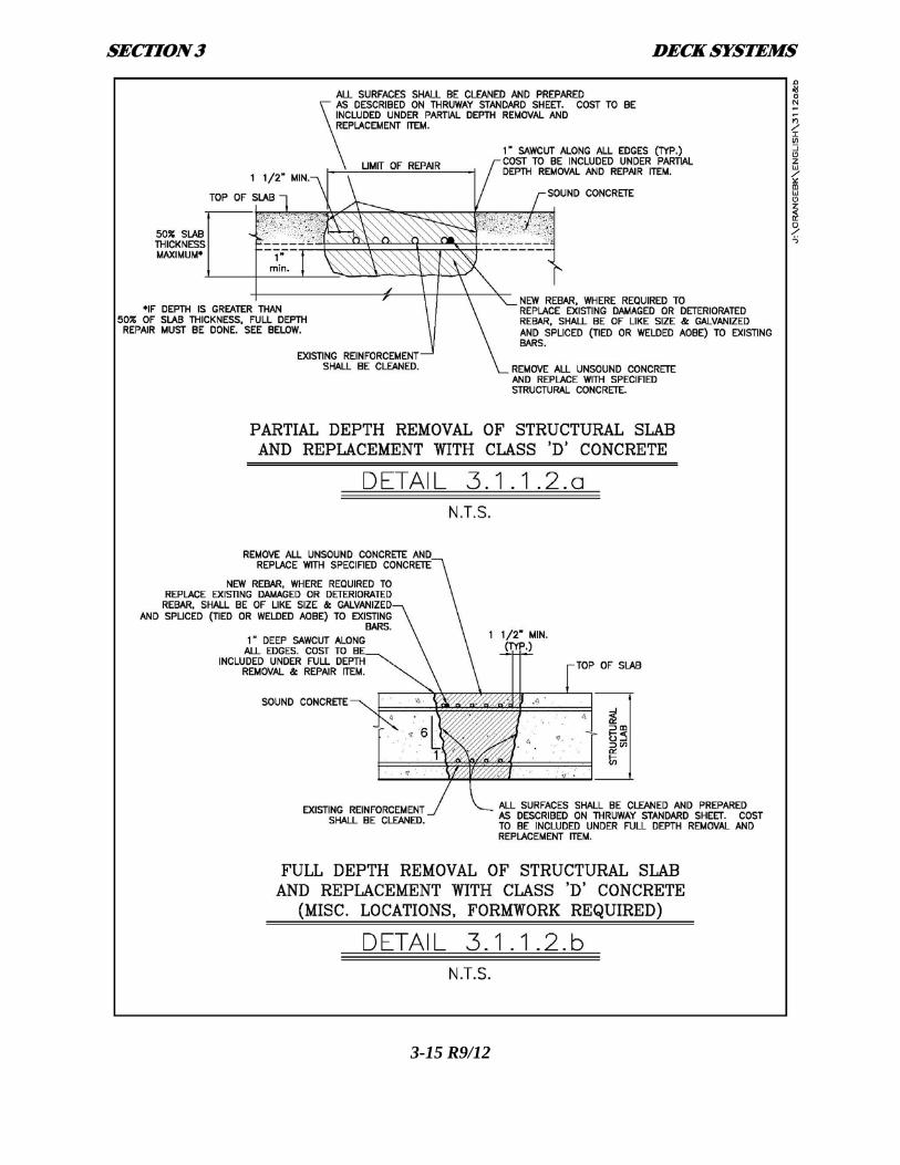
3.1.1.2b – TYPICAL DECK REPAIR DETAILS
See Details 3.1.1.2.a and 3.1.1.2.b for typical repair details.
3.1.1.3 - MONOLITHIC DECK (RIDING) SURFACE TEXTURE TREATMENT
New Monolithic Deck Surface Texturing: The initial surface friction on new bridge decks and
approach slabs is reduced by the cement paste coating on new deck surfaces, which wears off with
age to expose aggregate surfaces. NYSDOT Standard Specifications Subsection 557-3.07 –
“Finishing Integral Wearing Surfaces on Superstructure Slabs” requires an “artificial turf drag”
surface texture to be constructed on all new superstructure deck slabs and approach slabs
immediately following concrete placement and screeding.
SECTION 3 DECK SYSTEMS
3-15 R9/12

SECTION 3 DECK SYSTEMS
3-16 R9/12
The “artificial turf drag” surface is a “construction finish”, does not remove the cement paste finish,
and does not provide a desired “day-one” high-speed (>45 MPH) traffic surface friction. In addition;
the longitudinal tining specified to be placed on new PCC highway pavement (immediately
following the concrete pavement screeding) is perceived to corrupt the early surface concrete curing
of a bridge superstructure deck slab. For this reason bridge deck and approach slab concrete riding
surfaces must be reprofiled after adequate wet curing by longitudinal saw cut grooving or
longitudinal diamond grinding.
By Thruway policy; longitudinal saw cut grooving shall be applied to all monolithic bridge decks in
Albany, Syracuse, and Buffalo Divisions, and longitudinal diamond grinding shall be applied to all
monolithic deck surfaces in New York Division. The limits of these applications are from begin to
end of bridge (including approach slabs if applicable) to four inches from face of barrier/curb/swale.
3.1.2 – TWO-COURSE SUPERSTRUCTURE DECKS
3.1.2.1 - NEW TWO-COURSE SUPERSTRUCTURE DECKS
Two-course construction for new bridge decks shall only be used on bridges as described in
Subsection 3.0.1 – ”NEW AND REPLACEMENT BRIDGES”.
A new two-course bridge deck may use a bonded cement concrete overlay atop a cast-in-place
concrete structural deck, or a waterproofing membrane and asphalt concrete overlay over a cast-in-
place concrete structural deck.

SECTION 3 DECK SYSTEMS
3-17 R9/12
The concrete superstructure deck slab portion of a new two-course bridge deck shall be
“traditionally” reinforced and shall have a thickness of 8 ½”.
3.1.2.1a – BONDED CEMENT CONCRETE OVERLAY
The use of a new two-course bridge deck with a bonded cement concrete overlay shall be requested
and approved by the ACE during a bridge project’s scoping process.
New two-course bridge decks with bonded cement concrete overlays are not common, as they are
typically more expensive to construct than an equivalent monolithic concrete bridge deck. However;
there may be project requirements that can only be met by a two-course bridge deck with a bonded
cement concrete overlay. Cement concrete wearing surfaces can withstand high stresses where an
asphalt overlay might rut and shove, and construction staging requirements may require an overlay
to be used to provide the desired final surface profile across a structure constructed in stages.
The typical bonded cement concrete overlay is 2 inches thick, unreinforced, and can utilize various
optional types of concrete depending on thickness and/or design considerations. See NYSDOT
Standard Specifications Section 584 – “SPECIALIZED OVERLAYS FOR STRUCTURAL
SLABS” for additional work scope, material, and construction details.
3.1.2.1b –ASPHALT CONCRETE OVERLAY with DECK WATERPROOFING
The use of a new two-course bridge deck with an asphalt concrete overlay shall be requested and
approved by the ACE during a bridge project’s scoping process.
If an asphalt concrete overlay is requested and approved, the asphalt concrete overlay combined with
a means of waterproofing the superstructure deck on top of which it is placed shall be one of the
following three alternate systems:

SECTION 3 DECK SYSTEMS
3-18 R9/12
Alternates:
A. An Asphalt Concrete Overlay Over An Approved Sheet Membrane
An approved sheet membrane waterproofing system (a polymer fabric coated with
approximately 1/16” of highly modified bituminous material) shall be specified with an
appropriate 2 inch asphalt concrete overlay top course. Sheet membranes, being of uniform
thickness and documented good performance, are ideal for the protection of new and
rehabilitated decks.
The Designer must keep in mind that sheet membranes require a smooth and relatively flat
concrete deck surface to prevent punctures and tears during placement and overlaying. Refer
to the sheet membrane manufacturer’s recommendations for surface smoothness
requirements. The superstructure deck (being protected) must be dry when the sheet
membrane is applied to prevent moisture from creating blisters during the subsequent
placement of the HMA overlay. Clear directions should be included in the contract
documents for sheet membrane installation at weep tubes, scuppers, bridge joints, vertical
surfaces, etc., as well as overlap details. In addition; the designer must make sure that
adequate clearance, between phased membrane and overlay construction stages, can be
provided to allow the proper overlap of the membrane material during construction
operations without damaging it.
Asphalt concrete overlays (over an approved sheet membrane) being constructed on
Thruway mainline and ramp bridges shall be NYSDOT Standard Specifications Section 402
– “HOT MIX ASPHALT” items. For Additional HMA design guidance see Subsection
3.1.2.4.
SECTION 3 DECK SYSTEMS
3-19 R9/12
If the asphalt concrete overlay (over an approved sheet membrane) is being constructed on
an “overhead” bridge that will be maintained by NYSDOT or a local municipality, and the
overhead roadway’s AADT level does not exceed the maximums indicated in NYSDOT
Standard Specification Section 403-1, Asphalt Concrete; if requested by NYSDOT or the
municipality, a 2 inch thick “Marshal Mix” NYSDOT Standard Specifications Section 403 –
“HOT MIX ASPHALT (HMA) PAVEMENTS FOR MUNICIPALITIES” item may be used.
B. A Waterproofing Hot Mix Asphalt
A paveable single layer Waterproofing Hot Mix Asphalt, that acts as an HMA top course
and as a waterproofing layer/membrane, may be used for total single layer overlay
thicknesses less than or equal to 2 inches.
Paveable single layer Waterproofing Hot Mix Asphalt generally consists of an admixture
combined and mixed with either an HMA shim item, or HMA top course item, at the batch
plant. Since the “waterproofing” properties of the waterproofing HMA mix are integrated
into the HMA mix; it can be placed on rough surfaces, and can be installed rapidly in a one-
step paving operation. Note; single layer Waterproofing HMA is more costly than a sheet
membrane and asphalt overlay system; but it may be the only constructible deck
waterproofing system if construction requires the use of temporary short duration lane
closures to place an overlay .
C. A Waterproofing Hot Mix Asphalt Base Layer With An Asphalt Concrete Overlay
For total overlay thicknesses above 2 inches, a ¾ inch paveable single layer Waterproofing
Hot Mix Asphalt may be placed on the deck as a base waterproofing membrane and finished
with the necessary layer(s) of an appropriate asphalt overlay.

SECTION 3 DECK SYSTEMS
3-20 R9/12
3.1.2.2 - REHABILITATION OF EXISTING TWO-COURSE DECKS
All bridge deck rehabilitations for existing two-course decks shall be designed and detailed for a
bonded concrete overlay as the first option.
The rehabilitation of an existing two-course deck begins with a complete deck evaluation similar to
that described in Subsection 3.1.1.2 – Rehabilitation of Existing Monolithic Decks. The differences
between evaluating a monolithic bridge deck and a two-course bridge deck are due to the separate
wearing surface of the two-course deck. The separate wearing surface prevents the direct inspection
of the top of deck surface.
Two-course structural decks requiring more than 20% (assumed squared off value) full depth repairs
and 70% partial depth repairs (for a total of 90% of the existing deck area) shall be replaced. Based
on the level of deck deterioration; the decision to replace a two-course bridge deck (rather than
rehabilitate it) is typically made during the scoping process of a bridge project following a full deck
evaluation. Before pursuing a two-course deck rehabilitation, compare its cost to that of a new deck
and any other relevant factors, such as structure age, substructure condition, etc. Refer to the
NYSDOT Bridge Deck Evaluation Manual for making cost comparisons. Any decisions to replace a
two-course deck rehabilitation with a full deck replacement that are made after construction has
begun would create a significant contract cost increase.
Although visual inspection of an overlay can help in determining problem areas (continuously damp
areas, puddles, disintegrated overlay material), chain dragging of the wearing surface is ineffective
in determining accurate partial depth repair areas. Because of this, the area of partial depth repair
must be approximated. Figure 3.1.2.2 is a valuable tool used to determine the approximate amount of
partial depth repairs based on the amount of full depth repairs determined from the underside deck

SECTION 3 DECK SYSTEMS
3-21 R9/12
inspection.
Upon removal of an existing wearing course; all deteriorated deck concrete must be removed, and
corroded or damaged reinforcing steel must be repaired or replaced as needed. New concrete is
placed in the repair areas and allowed to cure. See Details 3.1.1.2.a and 3.1.1.2.b for typical repair
details. For additional information on concrete deck repairs refer to the Thruway Standard Sheet
“CONCRETE REPAIR FULL & PARTIAL DEPTH.dwg”.
A new wearing course overlay is installed over the rehabilitated deck surface using the same
guidance and details provided for the overlay course of a new two-course deck as described in
Subsection 3.1.2.1a – “BONDED CEMENT CONCRETE OVERLAY” or Subsection 3.1.2.1b –
“ASPHALT CONCRETE OVERLAY with DECK WATERPROOFING”.
Example Partial Depth Determination:
An underside deck inspection is done and it is determined that 9% of the total deck area requires full
depth repairs. Referring to Figure 3.1.2.2; if 9% of the total deck area requires full depth repairs,
then the expected partial depth repair area will be 30% of the total deck area. The total deck repairs
for this structure will be 39% of the total deck area.
Before pursuing the rehabilitation, compare its cost to that of a new deck and any other relevant
factors, such as structure age, substructure condition, etc. Refer to the NYSDOT Bridge Deck
Evaluation Manual for making cost comparisons.

SEC
TIO
N 3
D
EC
K SY
STE
MS
3-22 R
9/12

SECTION 3 DECK SYSTEMS
3-23 R9/12
3.1.2.3 – BONDED CEMENT CONCRETE OVERLAY (WEARING) SURFACE
TEXTURE TREATMENT
Bonded cement concrete overlay wearing surfaces shall have the same surface texture treatment as
monolithic decks. Refer to Subsection 3.1.1.3 - Monolithic Deck Riding Surface Treatment.
3.1.2.4 - HOT MIX ASPHALT OVERLAY DESIGN AND SPECIFICATION
Although the objective of the guidance given here is to allow the Designer to design and specify the
correct Hot Mix Asphalt (HMA) items to construct an asphalt overlay over a concrete superstructure
deck; the Designer must also consider the Hot Mix Asphalt items required for any highway paving
work that will be included with the bridge HMA overlay work being specified.
Typically; a minimal number of HMA items are to be specified for a single construction contract,
and the specified HMA items need to be appropriate for both the highway HMA paving portion of a
contract and the bridge HMA overlay portion of a contract. When the quantity of HMA placed as
highway pavement is significantly greater than the quantity placed as a bridge deck overlay(s) in a
single project, the HMA items specified are typically governed by highway paving requirements. An
HMA item chosen and specified as appropriate for both the highway paving and bridge overlay
work in a single contract, may require additional HMA contract guidance notes and construction
details to properly use that specific HMA item for both the highway paving and bridge overlay
work detailed. Designers can contact the Bureau of Highway Design or the Design Support Services
Bureau for assistance in choosing HMA items appropriate for a specific contract containing both
highway paving and bridge overlay work.

SECTION 3 DECK SYSTEMS
3-24 R9/12
The designer shall reference NYSTA Design Bulletins (DB 09-002) and (DB 09-003) in order to
become familiar with the design requirements for Authority placed asphalt concrete pavement.
Included in these design bulletins are design parameters that must be determined for the site to
properly formulate the required PG binder notes to be inserted into the proposal.
3.1.2.4a – REQUIRED PROJECT DATA FOR PG BINDER AND HMA ITEM SELECTION
For bridge deck overlays and bridge approach pavement; the designer shall design and specify
NYSDOT Standard Specification Section 402 series HMA items, or NYSDOT/NYSTA Special
Specification Section 402 series HMA items; unless directed otherwise. Section 402 series items are
based on “Superpave” Hot Mix Asphalt material specifications and design criteria; which can
incorporate the variability of material properties, environmental (weather and traffic) conditions and
construction quality into project specific HMA pavement designs.
In contrast; NYSDOT Standard Specification Section 403 series HMA items (which are being
phased out from use) are “Marshal Mix” HMA items having specific fixed HMA mix designs
(formulas), each created for a specific combination of broad design conditions. Past experiences with
specific 403 HMA mixes created the current “fixed” mix designs, and rigidly govern their use.
To specify Section 402 HMA items for use as a bridge deck asphalt concrete overlay, the Designer
must determine the following:
1) The project location establishes the environmental weather conditions to be designed for. For
Thruway projects, only two categories establish a project’s location, the project is either in
the “New York Division” or in the combined limits of the “Buffalo, Syracuse and Albany
Divisions”.

SECTION 3 DECK SYSTEMS
3-25 R9/12
2) Average Annual Daily Traffic Counts for each significantly different “zone” within a
project’s limits.
3) Truck Traffic percentages representing the percentage of the AADT made up of the
combined average daily percentages of FHWA Class 4 though Class 14 vehicles, which are
all of the “Commercial” vehicles in the daily AADT flow.
4) One or more Equivalent Single Axle Loads (ESALs) count(s) must be established that
represent traffic within the entire project limits, or that represent traffic within significantly
different zones within the project limits.
NYSTA Design Bulletin (DB 09-003) provides ESALs Count calculation guidance, a
“NYSTA Modified ESALs Count Spreadsheet”, and a source of AADT values and Truck
Traffic Percentages within the limits of the entire Thruway, all of which can be used to
estimate the ESALs count(s) for a project.
5) Average annual traffic speeds for each significantly different “traffic zone” within the
project limits. Assumed average annual traffic speeds only need to be accurate enough to
establish which one of three “average speed ranges” includes the average annual traffic
speed for each traffic zone within a project’s limits.
6) The designer must categorize the asphalt overlay work as maintenance/repair work,
rehabilitation work or new/replacement work. Maintenance/repair work and rehabilitation
work are grouped together when the work to be performed will allow the overlayed bridge
structure to function properly for the remaining service life of the bridge structure.
Rehabilitation work and new/replacement work are grouped together when the work to be

SECTION 3 DECK SYSTEMS
3-26 R9/12
performed will create an overlayed bridge structure with an extended service life, or the
service life a new structure.
3.1.2.4b – PG BINDER SELECTION AND PG BINDER SPECIAL NOTES FOR
CONTRACT PROPOSALS
Using the data collected in Subsection (3.1.2.4a) tasks (1) through (6) above; the Designer can used
the guidance of NYSTA Design Bulletins (DB 09-002): “Hot Mix Asphalt: PG Binder Design,
Selection & Special Note Guidance” and (DB 09-003): “ REVISED Thruway TEFs, and A Modified
Calculation of ESALs for Thruway Pavement Design” to select an appropriate PG Binder grade and
establish whether or not the PG binder will be “polymer-modified” for a project. This selection
process must be done with the concurrence of the associated Thruway Division Highway Engineer
to incorporate their division specific experiences with specific PG Binders.
When a PG Binder grade has been chosen and a decision whether or not to use a “polymer-
modified” PG Binder has been made; the Designer must create a project specific “Special Note for
Contract TA_xx-yy, Hot Mix Asphalt (HMA) Criteria” from one of the (2 sets of 2) division
specific “Special Notes” the are appended to DB 09-002. The PG Binder “Special Note” that must
be included in a project’s Proposal document will identify: i) the PG Binder grade chosen, ii) the
ESALs count range to be used in a project’s HMA mix design, iii) whether the PG Binder will or
will not be “polymer-modified”, and iv) whether the use of Polyphosphoric Acid (PPA) (see DB
09-002) will be prohibited (Buffalo, Syracuse & Albany Divisions) or conditionally allowed (New
York Division only).
3.1.2.4c – HMA BRIDGE DECK OVERLAY CROSS-SECTION

SECTION 3 DECK SYSTEMS
3-27 R9/12
Bridge deck asphalt overlays will typically consist of:
1. A 2-inch uniform thickness asphalt top course layer over an approved sheet membrane
waterproofing system, placed atop an existing or new concrete bridge deck, with no
modification of the bridge concrete superstructure deck cross-slope or vertical profile.
2. A Waterproofing Hot Mix Asphalt top course layer having a ¾-inch minimum and a 2-inch
maximum uniform thickness, placed over an existing or new concrete bridge deck, with no
modification of the bridge concrete superstructure deck cross-slope and a minimal correction
in the bridge deck vertical profile
3. A 3/4-inch uniform Waterproofing Hot Mix Asphalt base layer with a uniform or varying
thickness multiple course asphalt overlay can be placed to modify the bridge deck cross-slope
and vertical profile to match the cross-slope and vertical profile of the adjoining highway
section, that itself has been raised (possibly with a modified cross-slope) by one or more
asphalt overlays. Over the waterproofing hot mix asphalt; the multiple course asphalt overlay
could incorporate an initial truing and leveling course with a varying thickness to correct
revised deck cross-slopes; followed by a uniform top course layer, or a combination single
uniform top course layer atop a uniform binder layer, to correct and raise a bridge deck’s
vertical profile.
3.1.2.4d – HMA BRIDGE DECK OVERLAY ITEM NUMBER SELECTION
For bridge deck overlays and bridge approach pavement; the designer shall design and specify 402
series HMA items; unless directed otherwise.
The NYSDOT has included “Superpave” Section 402 Hot Mix Asphalt item design guidance in the
NYSDOT “Comprehensive Pavement Design Manual (CPDM)” Subsection 6.2 – “Hot Mix

SECTION 3 DECK SYSTEMS
3-28 R9/12
Asphalt”.
After the PG Binder has been selected following the procedures included in NYSTA (DB 09-002):
“Hot Mix Asphalt: PG Binder Design, Selection & Special Note Guidance”, (DB 09-003): “
REVISED Thruway TEFs, and A Modified Calculation of ESALs for Thruway Pavement Design”,
and NYSDOT CPDM Subsection 6.2 – “Hot Mix Asphalt” ; by the choice of a Series 402 HMA
item number, the Designer will be specifying the desired: i) aggregate size, ii) compaction method
series, and friction aggregate requirements. In addition: a “Plant Production Quality Adjustment”
item exists and is applied to all HMA items in a contract, and a “Pavement Density Quality
Adjustment” item exists and is applied only to HMA items specifying a “50 Series” compaction
(see NYSDOT CPDM Subsection 6.2.4 – “Interpreting HMA Item Numbers”).
A) Aggregate Size: See NYSDOT CPDM Subsection 6.2.7 – “Gradation Considerations” for
guidance on selecting the appropriate aggregate gradation size for each HMA layer of a bridge deck
overlay.
For an HMA mix, the maximum coarse aggregate size of an aggregate blend is used to identify that
aggregate blend. “Superpave” aggregate blends are detailed in Table 1 – “Design Controls Points” of
NYSDOT Materials Method 5.16 – “SUPERPAVE HOT MIX ASPHALT MIXTURE DESIGN
AND MIXTURE VERIFICATION PROCEDURES”.
For bridge deck asphalt overlays; the choices for nominal maximum aggregate size for a HMA top
SECTION 3 DECK SYSTEMS
3-29 R9/12
course are 1/2 inch and 3/8 inch. The typical maximum aggregate size for a top course is 1/2 inch,
which is considered more “rut resistant” that a 3/8 inch top course.
Required total overlay thicknesses can be governed by: i) the overlay thickness required to match an
adjacent highway pavement surface, ii) the required minimum layer thickness limited by the
maximum aggregate size used in each layer, or iii) the required maximum single layer thickness that
can be properly compacted in one lift. See NYSDOT CPDM Subsection 6.2.11 – “Lift Thickness
Limitations”.
B) Compaction Series: For NYSDOT HMA items four “compaction monitoring” levels exist, and
they are identified as the “Series 50 Compaction Method”, the “Series 60 Compaction Method”, the
“Series 70 Compaction Method” and the “Series 80 Compaction Method”. See NYSDOT Standard
Specifications Section 402 – “HOT MIX ASPHALT (HMA) PAVEMENTS”, Subsection 402-3.07
“Compaction” for the details of each compaction monitoring “Series”, and NYSDOT CPDM
Subsection 6.2.8 “Compaction Monitoring” for compaction “Series” choice guidance. The
compaction “Series” chosen is directly identified in the chosen HMA item numbers (see NYSDOT
CPDM Subsection 6.2.4 – “Interpreting HMA Item Numbers”).
For a bridge deck overlay that is part of a larger highway paving project; HMA item properties for
the HMA top course and (possibly binder) layer(s), including the compaction monitoring “Series” to
be applied to a layer, will be governed by, and the same as, the requirements of the adjacent highway
pavement. For each compaction monitoring “Series”; NYSDOT Subsection 402-3.07 “Compaction”
identifies that for bridge asphalt overlays the “Placement and compaction procedures will be
satisfactory when the procedures used in these areas obtain pavement density similar to that obtained
on the mainline pavement sections…. If a density gauge(s) is used to monitor mainline paving, use

SECTION 3 DECK SYSTEMS
3-30 R9/12
the same gauge(s) to monitor density of the above referenced areas”.
Stand alone bridge projects; that include asphalt items to: i) overlay a bridge deck and approach
slabs, ii) pave between a bridge’s approach slabs and existing highway pavement, iii) reconstruct
shoulders, and/or iv) construct temporary crossovers; should typically specify an HMA item
requiring the use of an “Series 80 Compaction Method”. Stand alone bridge projects typically use
small quantities of HMA that do not provide the opportunity to execute the construction of
pavement “test sections” as specified for the “Series 50 Compaction Method”, the “Series 60
Compaction Method” or the “Series 70 Compaction Method”.
NOTE: NYSDOT Subsection 402-3.07 “Compaction”, as modified by the current NYSTA
Addendum to the NYSDOT Standard Specifications specifically prohibits the use of vibratory
compaction of all HMA items on structural bridge decks.
C) Hot Mix Asphalt (HMA) Friction Requirements:
Within a project’s limits; the most stringent friction aggregate requirements for any location within
the project’s limits shall be applied to all top course HMA items.
The designer shall use the (Table – 3.1.2.4d) below to establish the HMA friction aggregate
requirements for a project.

SECTION 3 DECK SYSTEMS
HMA Friction Aggregate Type Selection Table – 3.1.2.4d
Highway System Traffic Location Aggregate
Type
High or Low Volume (1) New York Division Type F1 NYSTA Mainline and Ramp Bridges High or Low Volume (1)
Buffalo, Syracuse and Albany Divisions
Type F2
High Volume (1) New York Division Type F1
High Volume (1) Buffalo, Syracuse and
Albany Divisions Type F2 All Other Bridges
Low Volume (1) All Divisions Type F3
(1) “High Volume” refers to single lane bridges with design year AADT over 4000, 2 or 3 lane bridges with two-way design year AADT over 8,000, or bridges with 4 or more lanes with two-way design year AADT over 13,000. ”Low Volume” refers to bridges not meeting the aforementioned criteria.
NOTE: NYSDOT Standard Specification Section 400 – “Hot Mix Asphalt” Subsection 401-2.02D;
HMA aggregates identified as “Coarse Aggregate: Type F9 Conditions” are specifically prohibited
from being used in an HMA top course item that will permanently carry highway traffic during its
service life. In addition; highway shoulder pavement and highway cross-over pavement, that will
temporarily carry highway-speed traffic during the construction stages of a project, are also
prohibited from using HMA aggregates identified as “Coarse Aggregate: Type F9 Conditions”.
NOTE TO THE DESIGNER: The “friction aggregate” material requirements for Portland
Cement Concrete Section 501 items are different than the “friction aggregate” material
requirements for Hot Mix Asphalt Section 401 items. The names identifying friction aggregate
“Types” are similar for concrete and HMA items, but the aggregate gradation requirements for
the “friction aggregates” for concrete superstructure deck and approach slab items are different
from the aggregate gradation requirements for the “friction aggregates” for HMA pavement
items.
3-31 R9/12
SECTION 3 DECK SYSTEMS
3-32 R9/12
D) HMA “Plant Production Quality” Item:
For stand alone bridge projects; the designer shall include the appropriate Section 402 “Plant
Production Quality Adjustment” item associated with each HMA item specified. “Plant Production
Quality Adjustment” items are used with all compaction method “Series”.
3.1.2.4e – HOT MIX ASPHALT , VIBRATORY ROLLER COMPACTION PROHIBITION
ON BRIDGE SUPERSTRUCTURE DECKS:
NYSDOT Subsection 402-3.07 “Compaction”, as modified by the current NYSTA Addendum to the
NYSDOT Standard Specifications specifically prohibits the use of vibratory compaction of all
HMA items on structural bridge decks.
3.1.3 - REINFORCEMENT IN BRIDGE DECKS
Steel reinforcement in bridge decks shall be used to provide flexural, shear, and tensile strength to
the deck. Four mats (one each of longitudinal top and bottom and one each of transverse top and
bottom) of galvanized steel reinforcement shall be provided in all new bridge decks. Reinforcement
in new Thruway bridge decks shall be of the isotropic design where ever possible (see Subsection
3.1.3.1 below for use restrictions). Where conditions restrict the use of an isotropic deck, a
“Traditional” reinforced beam type deck shall be used and designed in accordance with the LFD
provisions of the AASHTO 17th Edition. See Subsection 3.1.3.2.
3.1.3.1 - GUIDELINES FOR ISOTROPIC REINFORCED BRIDGE DECKS
New bridge decks shall use isotropic reinforcement if all of the following criteria are met. If not, the
deck must be designed “Traditionally”.
SECTION 3 DECK SYSTEMS
3-33 R9/12
A. Deck Replacement or Bridge Replacement
B. The maximum spacing center-to-center of stringers shall be 10.0 feet.
C. The minimum spacing center-to-center of stringers shall be 5.0 feet.
D. There must be five or more stringers in the cross-section to allow for future staged
construction.
E. Monolithic deck thickness of 9 ½”. (8” design slab + 1 ½” Monolithic Wearing
Surface). See Detail 7.21.1.c.
F. Maximum live load deflection must be less than or equal to L/1000.
The following are detail requirements for isotropic bridge decks:
A. The reinforcement shall consist of two mats composed of #4 bars on 8 inch centers
with the longitudinal bars on top of both mats.
B. Cover above top longitudinal bars is 2 ½”. Cover below bottom transverse bars shall
be 1 ½”.
C. Both rebar mats shall be galvanized. Welded splices are not permitted.
D. The minimum fascia overhang from the centerline of the fascia girder shall be 2.0
feet with permanent concrete barrier, and 2.5 feet with any of the various types of
steel bridge rail.
E. Fascia overhang reinforcement shall be provided as indicated in Subsection 3.1.4.
F. Longitudinal bars are placed parallel to stringers. Transverse bars shall be placed
parallel the skew angle for skew angles up to and including 30˚. The transverse
reinforcement shall be placed normal to the stringers when the skew angle is greater
than 30˚. When reinforcement is placed on the skew, the 8 inch nominal
perpendicular bar spacing shall be reduced by the cosine squared of the skew angle.

SECTION 3 DECK SYSTEMS
3-34 R9/12
G. Additional longitudinal reinforcement in negative moment areas shall be provided as
required by Subsection 10.38.4.3 of the AASHTO 17th Edition.
H. The top and bottom reinforcing mats shall be staggered in both directions so that bars
are not directly over each other.
I. The depth of slab at the edge of the fascia should not be less than 10 ½” to allow
for cover for the railing/barrier anchorage.
3.1.3.2 - GUIDELINES FOR “TRADITIONALLY” REINFORCED BRIDGE DECKS
Where an isotropic type deck cannot be used, a “Traditional” beam type designed deck shall be used.
Tables have been included in this manual supplying design reinforcement criteria for most
circumstances in accordance with the LFD provisions of the AASHTO 17th Edition. For new
monolithic deck designs (9 ½” thick), Table 3.1.3.2.a or 3.1.3.2.b may be used. See Detail 7.21.1.c
for a typical new monolithic deck section. For new two-course deck designs (8 ½” thick deck w/ 2”
overlay), Table 3.1.3.2.c or 3.1.3.2.d may be used. See Details 7.21.1.a for a typical new two-course
deck section. The depth of slab at the edge of the fascia should not be less than 10 ½” to allow for
cover for the railing/barrier anchorage. For skews up to and including 30˚, the reinforcement shall be
placed parallel to the skew angle. For skews over 30˚, the reinforcement shall be placed normal to
the stringers. Refer to the appropriate BD Sheet for slab corner reinforcement for skews over 30˚.
The skewed reinforcement shall be detailed with the spacing along the stringers; not perpendicular to
the bars. Design span is defined as the perpendicular distance between stringers less one-half the
width of the top flange. Transverse reinforcing steel shall not be detailed with shop bends for deck
cross-slope changes. All bends of this nature shall be field bent as required by cover criteria.
Longitudinal distribution reinforcement in top of slab shall be no less than #5 bars at 18 inch centers.

SECTION 3 DECK SYSTEMS
3-35 R9/12

SECTION 3 DECK SYSTEMS
3-36 R9/12

SECTION 3 DECK SYSTEMS
3-37 R9/12

SECTION 3 DECK SYSTEMS
3-38 R9/12
SECTION 3 DECK SYSTEMS
3-39 R9/12
Spacing of the longitudinal (distribution) reinforcement at the bottom of slab shall be as described in
AASHTO 17th Edition Subsections 3.24.10 and 10.38.4.3. For existing monolithic and two-course
decks, reinforcement in repair areas shall be replaced in-kind. See Details 7.21.1.b and 7.21.1.d for
typical existing two-course and monolithic deck sections.
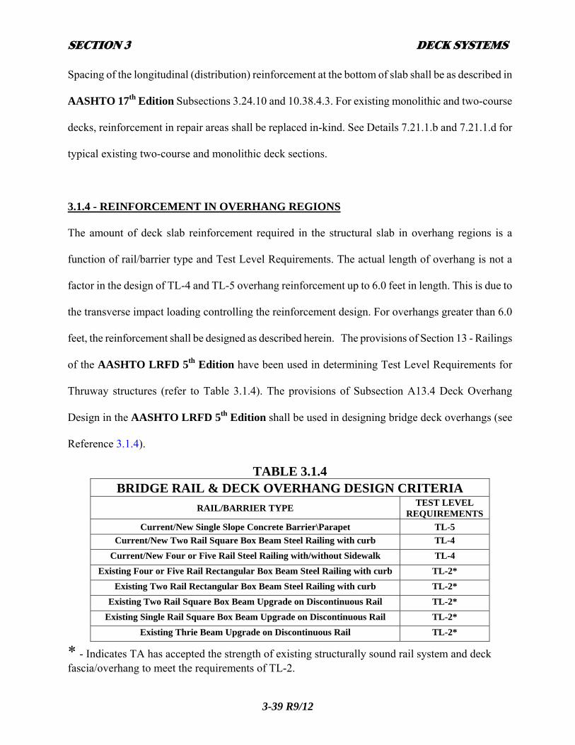
3.1.4 - REINFORCEMENT IN OVERHANG REGIONS
The amount of deck slab reinforcement required in the structural slab in overhang regions is a
function of rail/barrier type and Test Level Requirements. The actual length of overhang is not a
factor in the design of TL-4 and TL-5 overhang reinforcement up to 6.0 feet in length. This is due to
the transverse impact loading controlling the reinforcement design. For overhangs greater than 6.0
feet, the reinforcement shall be designed as described herein. The provisions of Section 13 - Railings
of the AASHTO LRFD 5th Edition have been used in determining Test Level Requirements for
Thruway structures (refer to Table 3.1.4). The provisions of Subsection A13.4 Deck Overhang
Design in the AASHTO LRFD 5th Edition shall be used in designing bridge deck overhangs (see
Reference 3.1.4).
TABLE 3.1.4
BRIDGE RAIL & DECK OVERHANG DESIGN CRITERIA
RAIL/BARRIER TYPE TEST LEVEL
REQUIREMENTS
Current/New Single Slope Concrete Barrier\Parapet TL-5
Current/New Two Rail Square Box Beam Steel Railing with curb TL-4
Current/New Four or Five Rail Steel Railing with/without Sidewalk TL-4
Existing Four or Five Rail Rectangular Box Beam Steel Railing with curb TL-2*
Existing Two Rail Rectangular Box Beam Steel Railing with curb TL-2*
Existing Two Rail Square Box Beam Upgrade on Discontinuous Rail TL-2*
Existing Single Rail Square Box Beam Upgrade on Discontinuous Rail TL-2*
Existing Thrie Beam Upgrade on Discontinuous Rail TL-2*
* - Indicates TA has accepted the strength of existing structurally sound rail system and deck fascia/overhang to meet the requirements of TL-2.

SECTION 3 DECK SYSTEMS
REFERENCE 3.1.4 DEFINITIONS: Short Term Rehabilitation: Bridge rehabilitation work that is only intended to make minor or
emergency repairs to a single element or various elements of the structure until the structure is
programmed for major rehabilitation or replacement within the next 10 to 15 years.
Long Term Rehabilitation: Bridge rehabilitation work that includes major repairs or replacement of
structural elements and the timeframe for major bridge rehabilitation or replacement is beyond 15
years.
SRSO’s – SRSO’s (Strip overlay, Repair deck, Seal deck, replace Overlay) cannot be universally
categorized as long term or short term work. The future work expected on the bridge and life
3-40 R9/12
SECTION 3 DECK SYSTEMS
expectancy of its main components must be considered in order to determine the appropriate rail
upgrade treatment on an SRSO project. The designer must look at several factors when determining
what rail treatment will be appropriate for an SRSO project. An original bridge that is nearing the end
of its life may be extended by performing an SRSO which may yield 10 or more years until complete
replacement. In this case, replacement is imminent. Treating a project like this as long term, and
performing extensive fascia/overhang and rail upgrades would not be warranted if the bridge is
intended to be replaced within the next 10 to 15 years. In this situation, short term rail upgrades
would be appropriate. However, on a previously replaced structure an SRSO may be required to a
deck that’s 20 or more years old. The structure as a whole and deck specifically should still have
several decades of useful life before replacement. In this case, the rail system should be addressed
within the SRSO project as described below as a long term repair.
Warrants - Railing treatment on rehabilitation projects is a complex subject with many project
specific considerations. The engineer shall review the list of warrants below and consider the
applicability of each in order to determine the best solution. Numerous considerations factor into
selecting the appropriate bridge railing treatment on a rehabilitation project. Evaluation of the
following contributing factors should provide sufficient information to identify the criteria that define
the logic on which the engineer’s decision is based:
A. Existing Bridge Railing - age, condition, original design criteria, materials, anchorage, snagging
characteristics, vault-causing features, discontinuities, transitions, fascia/overhang characteristics,
maintenance concerns and other contributing factors. See “Considerations Regarding the Repair of
Existing Rail Systems” on page 43.
B. Design Service Level – As described in Section 13 - Railings of the AASHTO LRFD 5th Edition 3-41 R9/12

SECTION 3 DECK SYSTEMS
C. Roadway System - Mainline, ramp, local, functional class, design speed, urban, rural, pedestrians,
bicycles, etc.
D. Roadway Characteristics - Horizontal and vertical geometry, visibility, AADT, DHV, percent
trucks, width, sidewalk, curb, median/median barrier, feature crossed, structure length, approaches
and any other contributing characteristics.
E. Safety/Accident Evaluation - Number and severity of accidents and their cause, indications of
bridge rail hits. Also, the type and extent of damage to the bridge railing shall be investigated. Two
or more accidents resulting in severe damage to the existing rail system would constitute an
“accident history”.
F. Historic/Aesthetic Considerations - Community input, SHPO input, Divisional discretion.
G. Drainage - Ability of system to accommodate roadway drainage and snow storage.
H. Safety Walks – Face-of-rail to face-of-curb dimension and curb height for vaulting
considerations.
I. Scope of Work - consider the railing upgrade/replacement in view of the rehabilitation project
from the perspective of appropriateness of work and increase in project cost.
J. Desired Service Life of the Repair - a “short term fix” may be appropriate in anticipation of
future work strategies.
K. Traffic - in some cases temporary traffic control considerations may greatly influence the scope
and type of bridge railing work that is feasible.
L. Transitions - Current and past Standard Railing systems also have an approved transition to the
highway guide railing. (See Subsection 3.1.4.3 – Bridge Transition Rail Selection Criteria)
3-42 R9/12

SECTION 3 DECK SYSTEMS
M. Deck Overhangs/fascias – Overall condition, percent full depth repairs required, depth of
concrete, amount and location of transverse overhang reinforcement. See “Considerations
Regarding the Repair/Upgrade of Deck Fascia/Overhang Concrete” on page 44.
N. Bridge Dead Load Capacity - Superstructure’s capacity to carry a heavier barrier system versus
an existing rail system. This may be a particular issue if fascia girders are lighter than interior girders.
During the scoping process, sound engineering judgment will be required to develop an appropriate
railing treatment justification for each structure to be rehabilitated. The following is general guidance
for the various applications that may be encountered on the Thruway system of bridges. It is meant to
assist the engineer with the scope of available and/or required upgrades depending on certain
conditions. Refer to Section 6 – Bridge Railing, of the NYSDOT Bridge Manual and the Thruway
Roadside Safety Specialist for additional information. In any case, the appropriate bridge
rail/barrier/parapet treatment for a given project shall be documented and explained in the
“Design Approval Document”.
Considerations Regarding the Repair of Existing Rail Systems: In the descriptions below,
reference is made to whether the existing rail system is “structurally sound” or not. During the
scoping of bridge rehabilitation projects, the Metals Engineering Unit will inspect existing rail
systems and make the determination whether a rail system is structurally sound or not. A rail system
that is without damage or deterioration will be considered structurally sound. A rail system with
damage or deterioration that, in the determination of the Metals Unit, can be repaired, will be
considered structurally sound after appropriate repairs are performed. If, in the determination of the
Metals Unit, a deteriorated or damaged rail system cannot reasonably and effectively be repaired, it
will be considered not being structurally sound and must be replaced.
3-43 R9/12

SECTION 3 DECK SYSTEMS
Considerations Regarding the Repair/Upgrade of Deck Fascia/Overhang Concrete: In the
descriptions below, reference is made to the repair/upgrade of fascia/overhang concrete. When an
existing rail system is to be retained, fascia and overhang repairs shall be limited to removal of
unsound concrete, replacement of deteriorated or damaged reinforcing steel with like-sized,
galvanized reinforcing, and replacement of concrete using standard Authority details and construction
practices. When a rail system is to be replaced with a new TL-4 or TL-5 system, one of the
following deck fascia and overhang upgrades shall be performed:
For Short Term Rehabilitation, the deck fascia and overhang shall be repaired as needed and a
monodeck removal and replacement shall be completed regardless of the amount of deterioration. The
monodeck removal shall be to a depth of 2.0 inches below the bottom of the top mat of existing
reinforcement to a width from the fascia to 2’-6” beyond the centerline of the fascia girder toward the
first interior girder and be supplemented with required partial and full depth repairs and the
appropriate amount of replacement and additional galvanized overhang reinforcement for the TL-4
rail system prior to placing the new concrete.
For Long Term Rehabilitation, if the deck concrete in the overhang region is not structurally sound
(equal to or greater than 20% full depth repairs expected), it shall not be repaired. The deck overhang
shall be removed and replaced to a width from the fascia to 2’-6” beyond the centerline of the fascia
girder toward the first interior girder and include the appropriate amount of replacement and
overhang reinforcement for the barrier/rail system used. If the deck concrete in the overhang region is
structurally sound (less than 20% full depth repairs expected), the deck fascia and overhang shall be
repaired as needed with full and partial depth deck repairs and a monodeck removal shall be 3-44 R9/12

SECTION 3 DECK SYSTEMS
completed to remove all concrete to a depth of 2.0 inches below the bottom of the top mat of existing
reinforcement to a width from the fascia to 2’-6” beyond the centerline of the fascia girder toward
the first interior girder and be supplemented with the appropriate amount of replacement and
additional galvanized overhang reinforcement for the TL-4 or TL-5 barrier/rail system used prior to
placing the new concrete. Refer to Details 3.1.4.2.a through 3.1.4.2.f. for typical TL-4 and TL-5
overhang reinforcement size and spacing requirements.
3.1.4.1 – THRUWAY RAIL/BARRIER AND OVERHANG DESIGN POLICY 3.1.4.1.1 – NEW AND REPLACEMENT MAINLINE AND RAMP BRIDGES
All Mainline and Ramp Thruway Bridges to be replaced shall be designed and detailed using the
Thruway standard 3’-6” high TL-5 single sloped concrete bridge barrier system at both the left and
right fascias. See Details 3.1.4.2.b and 3.1.4.2.f for typical TL-5 barrier and overhang reinforcement
size and spacing requirements.
3.1.4.1.2 – REHABILITATED MAINLINE AND RAMP BRIDGES – Short Term
Existing Discontinuous Four Rail with no Upgrade, with Thrie Beam Upgrade, or Single Box Beam Upgrade: Mainline and Ramp Bridges to receive a short term rehabilitation… Shall Install Two Rail Box Beam Upgrade IF:
Existing rail IS structurally sound, and Fascia concrete IS structurally sound
Shall Install New TL-4 Bridge Rail System with Monodeck Fascia Upgrades IF:
Existing rail IS NOT structurally sound, or Fascia concrete IS NOT structurally sound
Refer to Subsection 3.1.4 (page 44) for deck fascia monodeck repair criteria and details.
3-45 R9/12

SECTION 3 DECK SYSTEMS
Existing Discontinuous Four Rail with Two Rail Box Beam Upgrade: Mainline and Ramp Bridges to receive a short term rehabilitation… May Retain Existing Rail System IF:
Existing rail IS structurally sound, and Fascia concrete IS structurally sound
Shall Install New TL-4 Bridge Rail System with Monodeck Fascia Upgrades IF:
Existing rail IS NOT structurally sound, or Fascia concrete IS NOT structurally sound
Refer to Subsection 3.1.4 (page 44) for deck fascia monodeck repair criteria and details.
Existing Continuous Two Rail Curb/Curbless or Four Rail Curb/Curbless: Mainline and Ramp Bridges to receive a short term rehabilitation… May Retain Existing Rail System IF:
Existing rail IS structurally sound, and Fascia concrete IS structurally sound
Shall Install New TL-4 Bridge Rail System with Monodeck Fascia Upgrades IF:
Existing rail IS NOT structurally sound, or Fascia concrete IS NOT structurally sound
Refer to Subsection 3.1.4 (page 44) for deck fascia monodeck repair criteria and details.
3.1.4.1.3 – REHABILITATED MAINLINE AND RAMP BRIDGES – Long Term
Existing Discontinuous Four Rail with no Upgrade, Thrie Beam Upgrade, or Single Box Beam Upgrade: Mainline and Ramp Bridges to receive a long term rehabilitation… Shall Install Two Rail Box Beam Upgrade IF:
Existing rail IS structurally sound, and Fascia concrete IS structurally sound, and No Accident History Exists
Shall Install New TL-5 Barrier System with Monodeck Fascia Upgrades IF:
Existing rail IS NOT structurally sound, and
3-46 R9/12
SECTION 3 DECK SYSTEMS
Fascia concrete IS structurally sound With or without accident history
Shall Install New TL-5 Barrier System with New Deck Fascias IF:
Existing rail IS NOT structurally sound, and Fascia concrete IS NOT structurally sound With or without accident history
Refer to Subsection 3.1.4 (page 44) for deck fascia monodeck repair and replacement criteria and
details.
Existing Discontinuous Four Rail with Two Rail Box Beam Upgrade: Mainline and Ramp Bridges to receive a long term rehabilitation… May Retain Existing Rail System IF:
Existing rail IS structurally sound, and Fascia concrete IS structurally sound, and No Accident History Exists
Shall Install New TL-5 Barrier System with Monodeck Fascia Upgrades IF:
Existing rail IS NOT structurally sound, and Fascia concrete IS structurally sound With or without accident history
Shall Install New TL-5 Barrier System with New Deck Fascias IF:
Existing rail IS NOT structurally sound, and Fascia concrete IS NOT structurally sound With or without accident history
Refer to Subsection 3.1.4 (page 44) for deck fascia monodeck repair and replacement criteria and
details.
Existing Continuous Two Rail Curb/Curbless: Mainline and Ramp Bridges to receive a long term rehabilitation… May Retain Existing Rail System IF:
Existing rail IS structurally sound, and Fascia concrete IS structurally sound, and
3-47 R9/12
SECTION 3 DECK SYSTEMS
No Accident History Exists Shall Install New TL-5 Barrier System with Monodeck Fascia Upgrades IF:
Existing rail IS NOT structurally sound, and Fascia concrete IS structurally sound With or without accident history
Shall Install New TL-5 Barrier System with New Deck Fascias IF:
Existing rail IS NOT structurally sound, and Fascia concrete IS NOT structurally sound With or without accident history
Refer to Subsection 3.1.4 (page 44) for deck fascia monodeck repair and replacement criteria and
details.
Existing Continuous Four Rail Curb/Curbless: Mainline and Ramp Bridges to receive a long term rehabilitation… May Retain Existing Rail System IF:
Existing rail IS structurally sound, and Fascia concrete IS structurally sound, and No Accident History Exists
Shall Install New TL-5 Barrier System with Monodeck Fascia Upgrades IF:
Existing rail IS NOT structurally sound, and Fascia concrete IS structurally sound With or without accident history
Shall Install New TL-5 Barrier System with New Deck Fascias IF:
Existing rail IS NOT structurally sound, and Fascia concrete IS NOT structurally sound With or without accident history
Refer to Subsection 3.1.4 (page 44) for deck fascia monodeck repair and replacement criteria and
details.
3.1.4.1.4 – NEW AND REPLACEMENT OVERHEAD BRIDGES
3-48 R9/12
SECTION 3 DECK SYSTEMS
All Overhead Bridges to be replaced shall be designed and detailed using a Thruway standard TL-5
concrete barrier/parapet system. Although some overhead bridges may not have the heavy truck
traffic that a mainline or ramp bridge may have, it is prudent to protect the mainline below overhead
bridges with the stronger TL-5 system rather than the TL-4 system. The cost differential is minimal
on a replacement project, and the TL-5 system would not require upgrading if truck traffic or accident
history were to change over the long expected service life of a new structure. Bridge shoulders
without sidewalks shall use the Thruway standard 3’-6” high single sloped concrete barrier system.
See Details 3.1.4.2.b and 3.1.4.2.f for typical TL-5 barrier and overhang reinforcement size and
spacing requirements. Bridge shoulders that include a sidewalk shall use the Thruway standard 3’-6”
high vertical faced concrete parapet at the deck fascia/overhang. See Details 3.1.4.2.c and 3.1.4.2.f for
typical TL-5 parapet and overhang reinforcement size and spacing requirements. Sight distance
requirements at the site shall be reviewed during the scoping phase of the project. If the appropriate
concrete barrier system will create unsafe sight distance conditions, an approved four or five rail TL-
4 steel railing system may be used. See Details 3.1.4.2.d through 3.1.4.2.f for typical TL-4 overhang
reinforcement size and spacing requirements.
3.1.4.1.5 – REHABILITATED OVERHEAD BRIDGES – Short Term
Existing Discontinuous Four-Rail with no Upgrade: Overhead Thruway Bridges to receive a short term rehabilitation… Shall Install Thrie Beam Upgrade IF:
Existing rail IS structurally sound, and Fascia concrete IS structurally sound, and Posted speed is 35 MPH or lower
Shall Install Two Rail Box Beam Upgrade IF:
Existing rail IS structurally sound, and Fascia concrete IS structurally sound, and
3-49 R9/12
SECTION 3 DECK SYSTEMS
Posted speed is above 35 MPH Shall Install New TL-4 Rail System with Monodeck Fascia Upgrades IF:
Existing rail IS NOT structurally sound, or Fascia concrete IS NOT structurally sound
Refer to Subsection 3.1.4 (page 44) for deck fascia monodeck repair criteria and details.
Existing Discontinuous Four-Rail with Thrie Beam Upgrade or Single Box Beam Upgrade:
Overhead Thruway Bridges to receive a short term rehabilitation… May Retain Existing Rail System IF:
Existing rail IS structurally sound, and Fascia concrete IS structurally sound, and Posted speed is 35 MPH or lower
Shall Install Two Rail Box Beam Upgrade IF:
Existing rail IS structurally sound, and Fascia concrete IS structurally sound, and Posted speed is above 35 MPH
Shall Install New TL-4 Rail System with Monodeck Fascia Upgrades IF:
Existing rail IS NOT structurally sound, or Fascia concrete IS NOT structurally sound
Refer to Subsection 3.1.4 (page 44) for deck fascia monodeck repair criteria and details.
Existing Discontinuous Four-Rail with existing Two Rail Box Beam Upgrade: Overhead Thruway Bridges to receive a short term rehabilitation… May Retain Existing Rail System IF:
Existing rail IS structurally sound, and Fascia concrete IS structurally sound
Shall Install New TL-4 Rail System with Monodeck Fascia Upgrades IF:
Existing rail IS NOT structurally sound, or Fascia concrete IS NOT structurally sound
Refer to Subsection 3.1.4 (page 44) for deck fascia monodeck repair criteria and details.
3-50 R9/12

SECTION 3 DECK SYSTEMS
Existing Continuous Two-Rail Curb/Curbless or Four Rail Curb/Curbless: Overhead Thruway Bridges to receive a short term rehabilitation… May Retain Existing Rail System IF:
Existing rail IS structurally sound, and Fascia concrete IS structurally sound
Shall Install New TL-4 Rail System with Monodeck Fascia Upgrades IF:
Existing rail IS NOT structurally sound, or Fascia concrete IS NOT structurally sound
Refer to Subsection 3.1.4 (page 44) for deck fascia monodeck repair criteria and details.
3.1.4.1.6 – REHABILITATED OVERHEAD BRIDGES – Long Term
Existing Discontinuous Four-Rail with no Upgrade, Thrie Beam Upgrade, or Single Box Beam Upgrade: Overhead Thruway Bridges to receive a long term rehabilitation… Shall Install Two Rail Box Beam Upgrade IF:
Existing rail IS structurally sound, and Fascia concrete IS structurally sound, and No accident history exists
Shall Install New TL-4 Rail System with Monodeck Fascia Upgrades IF:
Existing rail IS NOT structurally sound, and Fascia concrete IS structurally sound, and No accident history exists
Shall Install New TL-4 Rail System with New Deck Fascias IF:
Existing rail IS NOT structurally sound, and Fascia concrete IS NOT structurally sound, and No accident history exists
Shall Install New TL-5 Barrier/Parapet System with Monodeck Fascia Upgrades IF:
Existing rail IS NOT structurally sound, and Fascia concrete IS structurally sound, and Accident history exists
Shall Install New TL-5 Barrier/Parapet System with New Deck Fascias IF: 3-51 R9/12

SECTION 3 DECK SYSTEMS
Existing rail IS NOT structurally sound, and Fascia concrete IS NOT structurally sound, and Accident history exists
Refer to Subsection 3.1.4 (page 44) for deck fascia monodeck repair and replacement criteria and
details.
Existing Discontinuous Four-Rail with Two Rail Box Beam Upgrade: Overhead Thruway Bridges to receive a long term rehabilitation… May Retain Existing Rail System IF:
Existing rail IS structurally sound, and Fascia concrete IS structurally sound, and No accident history exists
Shall Install New TL-4 Rail System with Monodeck Fascia Upgrades IF:
Existing rail IS NOT structurally sound, and Fascia concrete IS structurally sound, and No accident history exists
Shall Install New TL-4 Rail System with New Deck Fascias IF:
Existing rail IS NOT structurally sound, and Fascia concrete IS NOT structurally sound, and No accident history exists
Shall Install New TL-5 Barrier/Parapet System with Monodeck Fascia Upgrades IF:
Existing rail IS NOT structurally sound, and Fascia concrete IS structurally sound, and Accident history exists
Shall Install New TL-5 Barrier/Parapet System with New Deck Fascias IF:
Existing rail IS NOT structurally sound, and Fascia concrete IS NOT structurally sound, and Accident history exists
Refer to Subsection 3.1.4 (page 44) for deck fascia monodeck repair and replacement criteria and
details.
Existing Continuous Two-Rail Curb/Curbless: 3-52 R9/12

SECTION 3 DECK SYSTEMS
Overhead Thruway Bridges to receive a long term rehabilitation… May Retain Existing Rail System IF:
Existing rail IS structurally sound, and Fascia concrete IS structurally sound, and No accident history exists
Shall Install New TL-4 Rail System with Monodeck Fascia Upgrades IF:
Existing rail IS NOT structurally sound, and Fascia concrete IS structurally sound, and No accident history exists
Shall Install New TL-4 Rail System with New Deck Fascias IF:
Existing rail IS NOT structurally sound, and Fascia concrete IS NOT structurally sound, and No accident history exists
Shall Install New TL-5 Barrier/Parapet System with Monodeck Fascia Upgrades IF:
Existing rail IS NOT structurally sound, and Fascia concrete IS structurally sound, and Accident history exists
Shall Install New TL-5 Barrier/Parapet System with New Deck Fascias IF:
Existing rail IS NOT structurally sound, and Fascia concrete IS NOT structurally sound, and Accident history exists
Refer to Subsection 3.1.4 (page 44) for deck fascia monodeck repair and replacement criteria and
details.
Existing Continuous Four-Rail Curb/Curbless: Overhead Thruway Bridges to receive a long term rehabilitation… May Retain Existing Rail System IF:
Existing rail IS structurally sound, and Fascia concrete IS structurally sound, and No accident history exists
Shall Install New TL-4 Rail System with Monodeck Fascia Upgrades IF:
Existing rail IS NOT structurally sound, and Fascia concrete IS structurally sound, and
3-53 R9/12
SECTION 3 DECK SYSTEMS
No accident history exists Shall Install New TL-4 Rail System with New Deck Fascias IF:
Existing rail IS NOT structurally sound, and Fascia concrete IS NOT structurally sound, and No accident history exists
Shall Install New TL-5 Barrier/Parapet System with Monodeck Fascia Upgrades IF:
Existing rail IS NOT structurally sound, and Fascia concrete IS structurally sound, and Accident history exists
Shall Install New TL-5 Barrier/Parapet System with New Deck Fascias IF:
Existing rail IS NOT structurally sound, and Fascia concrete IS NOT structurally sound, and Accident history exists
Refer to Subsection 3.1.4 (page 44) for deck fascia monodeck repair and replacement criteria and
details.
3.1.4.2 – OVERHANG REINFORCEMENT DESIGN CRITERIA
For the TL-4 and TL-5 barrier/parapet/rail types listed in Table 3.1.4, the following design
assumptions are made:
A. Three cases (fascia/overhang configurations) are investigated:
1. Single Slope Concrete Barrier\Concrete Parapet w/sidewalk (TL-5)
2. Two Rail Steel Railing with curb (TL-4)
3. Four Rail Steel Railing with/without sidewalk/curb (TL-4)
B. Assumptions made in investigating the above-mentioned cases are:
1. Critical section for imbedment length = centerline of fascia stringer.
(Overhang reinforcement should be extended at least 2’-4” or imbedment
length [whichever is greater] beyond this point toward first interior stringer.)
2. Design overhang = Overhang - (25% of Top Flange Width).
3-54 R9/12

SECTION 3 DECK SYSTEMS
3. Overhang slab thickness (including haunch) = 10 ½” or 12”.
4. Wheel Load = 16 kips x 1.25.
5. Transverse Impact Load = 124 kips (TL-5), 54 kips (TL-4)
6. Bar Reinforcement = Grade 60 (Fy = 60 ksi).
7. F′c = 3,000 psi.
8. Design Depth (d) = 8” or 9 ½”.
Top overhang reinforcement shall be provided with a hook to develop the required reinforcement
within 1’-0” from the fascia. This may be accomplished by either: a) providing additional hooked
reinforcement between the design slab reinforcement; b) hooking the design slab reinforcement;
and/or c) lapping additional hooked reinforcement to the design slab reinforcement within the first
interior bay. For new construction laps shall be staggered by placing them at the slab inflection
points, such that no two consecutive bars are spliced in the same bay or inflection point. The Thruway
Authority has developed typical overhang design reinforcement details that may be used on all
overhangs less than or equal to 6’-0”. See Details 3.1.4.2.a thru 3.1.4.2.f on the following sheets.
3-55 R9/12

SECTION 3 DECK SYSTEMS
ISOMETRIC VIEW OF TYPICAL OVERHANG REINFORCEMENT
DETAIL 3.1.4.2.a
3-56 R9/12

SECTION 3 DECK SYSTEMS
3-57 R9/12

SECTION 3 DECK SYSTEMS
3-58 R9/12

SECTION 3 DECK SYSTEMS
3-59 R9/12

SECTION 3 DECK SYSTEMS
3-60 R9/12

SECTION 3 DECK SYSTEMS
3-61 R9/12

SECTION 3 DECK SYSTEMS
3-62 R9/12
3.1.4.3 – BRIDGE TRANSITION RAIL SELECTION CRITERIA
The bridge rail transition type to use is dependent on the bridge rail/barrier type and the approach
rail type. The appropriate transition types for the various bridge and approach rail configurations are
as follows:
1. Discontinuous four rail bridge rail with a thrie beam upgrade shall use a thrie beam
transition. This will transition directly into any type of corrugated beam guide rail. If the
approach rail is box beam, then a corrugated to box beam transition will also be required.
2. Discontinuous four rail bridge rail with a single box beam upgrade shall use a single box
beam transition. This will transition directly into box beam guide rail. If the approach rail is
corrugated beam, then a box beam to corrugated beam transition will also be required.
3. Discontinuous four rail bridge rail with a two rail box beam upgrade shall use a two rail
box beam transition. This will transition directly into box beam guide rail. If the approach
rail is corrugated beam, then a box beam to corrugated beam transition will also be required.
4. Two rail bridge rail shall use a two rail box beam transition. This will transition directly
into box beam guide rail. If the approach rail is corrugated beam, then a box beam to
corrugated beam transition will also be required.
5. Four and five rail bridge rail shall use a two rail box beam transition. This will transition
directly into box beam guide rail. If the approach rail is corrugated beam, then a box beam to
corrugated beam transition will also be required.
6. On the approach ends of single slope concrete barrier, a face mounted two rail box beam
transition shall be used if the approach rail is box beam. If the approach rail is corrugated,
SECTION 3 DECK SYSTEMS
3-63 R9/12
then the thrie beam transition shall be used. On the trailing ends of single slope concrete
barrier, an end mounted two rail box beam transition shall be used if the approach rail is
box beam. If the approach rail is corrugated, then the thrie beam transition shall be used.
7. Vertical concrete parapet with sidewalks shall use an end mounted two rail box beam
transition on approach and trailing ends. This will transition directly into box beam guide
rail. If the approach rail is corrugated beam, then a box beam to corrugated beam transition
will also be required.
8. “Tuning Fork” transitions on any structure shall be removed on all short term and
long term projects and replaced with the two rail box beam transition.
Thruway Authority Standard Plan Sheets for the thrie beam transition, face mounted two rail box
beam transition, and the end mounted two rail box beam transition are located in ProjectWise.
Standard details for transitions between corrugated beam guide rail (weak post & heavy post block
out) and box beam guide rail are located on current NYSDOT Standard Sheets.
3.1.5 - HAUNCHES
All steel stringer bridges with cast-in-place concrete deck slabs shall be provided with a concrete
haunch over each stringer, placed monolithically with the slab. This haunch is provided as a
construction tolerance for stringer camber. For flange widths under 16 inches, the minimum depth
of haunch at the supports shall be 2 inches as measured along the centerline of web from the top of
steel to the theoretical bottom of slab. For top flange widths of 16 inches or more, the 2 inch
minimum shall be measured from the edge of flange. In these cases a deeper minimum haunch at the

SECTION 3 DECK SYSTEMS
3-64 R9/12
centerline of web may result due to the roadway cross slope. The haunch depth between supports
will vary depending on the accuracy of the girder final camber. The allowable camber tolerance for
girders is +3/4”, -0”. In no case shall the girder steel be allowed to protrude into the deck (negative
haunch). See Girder Haunch Detail on sheet C6-2 of Appendix C. If the top flange is of varying
thickness or includes a cover plate, the 2 inch shall be measured at the point of maximum top flange
thickness (i.e., with a 3 inch thick top flange at the pier and a 2 inch thick top flange at the abutment,
the minimum haunch shall be 2 inches thick at the pier and 3 inches thick at the abutment).
For bridges with a crest vertical curve or no vertical curve, the depth of the haunch at the centerline
of bearings shall be the minimum depth, plus the difference in thickness between the maximum and
minimum top flange plates, plus the correct allowance for horizontal curvature. For sag vertical
curves, the girders shall be straight whenever possible. The point of minimum haunch shall be at
some point between the supports. Refer to Subsection 7.3 – Camber, for additional information.
Fascia beams of non-continuous multi-span bridges shall be set so that the top of the webs of fascia
beams in adjacent spans line up vertically. This will ensure a constant fascia depth for the entire
length of the structure. See Subsection 7.21 – Shear Connectors, for information on shear studs and
reinforcement in haunches.
3.1.6 - FORMING
Removable or stay-in-place (corrugated metal) forms shall be used on all Thruway Authority

SECTION 3 DECK SYSTEMS
3-65 R9/12
structures. If the structure has an expansion joint, and stay-in-place forms are used, one transverse
line of forms at the low end of each span at the joint will be required to be removed for future
inspection purposes. The detail shown on sheet C6-9 of Appendix C shall be shown on the contract
plans. This detail shows the cross section of a typical deck with stay-in-place forms. When stay-in-
place forms are used, the corrugations shall be filled with Styrofoam. The weight of the stay-in-
place forms including Styrofoam shall be taken as 4.0 psf.
3.1.6.1 – TEMPORARY OVERHANG BRACKET DESIGN
The current AASHTO LRFD 5th Edition advises that the effects of temporary overhang brackets be
analyzed for the effects on the structural steel members. These effects will primarily cause
differential deflection and torsional stresses in the fascia girders. The girders, diaphragms, lateral
bracing (if necessary), and connections need to be designed/analyzed to handle these temporary
loads. To this end, the Designer shall follow the overhang bracket design procedures in the 1995
AASHTO CONSTRUCTION HANDBOOK FOR TEMPORARY WORKS - APPENDIX B. The
designer shall ensure that the bridge steel has been designed to resist the maximum loads and
moments calculated. There is a Thruway Structures Standard Sheet in ProjectWise titled “Deck
Fascia Overhang Bracket Details & Notes” that shall be included in the project plans.
3.1.7 - CONCRETE PLACEMENT
The effects of concrete placement must be analyzed during design and any relevant information shall
be placed in the contract documents. The analysis will give the designer an understanding of the
potential structural behavior during placement and help to minimize undesirable results such as deck
SECTION 3 DECK SYSTEMS
3-66 R9/12
cracks. Based on the results of this analysis, the contract documents can either offer or restrict the
contractor's placement options. The following definitions will be used:
Continuous Placement - A placement that starts at one end of a structural deck and
finishes at the opposite end with no construction joints.
Generally, the ends are at bridge joints or at the abutments.
See Details 3.1.7.a and 3.1.7.b.
Sequential Placement - A series of individual placements. Generally, positive dead-
load moment areas are placed first, allowed to cure for 72
hours, then the negative dead-load moment areas are placed.
See Details 3.1.7.c and 3.1.7.d.
Alternate Placement - An alternative proposed by the contractor or Engineer as an
improvement or a modification of the other methods.
Improved placement practices have increased the number of contractors requesting to place more
bridge deck concrete continuously rather than sequentially. The use of set retarding admixtures
allows the concrete to remain plastic for up to 6 hours.

SECTION 3 DECK SYSTEMS
3-67 R9/12

SECTION 3 DECK SYSTEMS
3-68 R9/12

SECTION 3 DECK SYSTEMS
3-69 R9/12
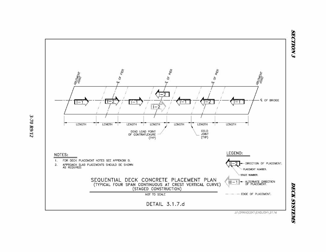
SEC
TIO
N 3
D
EC
K SY
STE
MS
3-70 R
9/12
SECTION 3 DECK SYSTEMS
3-71 R9/12
Ready-mix batch plants can generally produce 60 yd3/HR or more, so placement rates of 30
yd3/HR/finishing machine are attainable. Concrete pump trucks also contribute to this placement
rate by keeping fresh concrete deposited in front of the advancing finishing machine. These pump
trucks can deposit fresh concrete 200 feet or more away from where they are parked. With this in
mind, the designer must calculate the volume of concrete in a particular placement and decide
whether it can be done continuously or only sequentially. Next, the effects on the structure must be
investigated, such as beam stability and uplift at supports. The use of shallow depth continuous
beams to maintain vertical under clearance and elimination of shoulder piers of overhead bridges
will contribute to increased deflections and potential uplift. Simple span bridges present less of a
problem than continuous bridges, but should be checked just the same. The completed analysis will
serve to support the decisions made should questions arise in the future.
Both methods should be offered in the contract documents unless continuous placement is restricted
from use based on the results of the analysis. Regardless, the contractor will be required to submit a
detailed plan for review and approval stating the following:
A. How the concrete will be placed using the equipment, personnel, and any other
required resources.
B. The quantity, type, and rate of placement features of the equipment to be used in this
work.
C. Contingencies for changes in weather, equipment breakdowns, batch plant delays, or
any other factors that could delay or stop this work.

SECTION 3 DECK SYSTEMS
3-72 R9/12
D. How placement operations will be stopped if required and how the end of placement
will be finished.
E. An anticipated rate of concrete volume placed per hour.
This is just a basic list. Additional information should be requested based on the results of the
analysis. An example would be if uplift were anticipated during placement, the contractor must
describe how it will be addressed. See Appendix B for sample notes.
3.1.7.1 - CONTINUOUS PLACEMENT
This is generally the method used during construction. But before this option is placed in the plans,
the analysis must consider factors that would preclude it. These factors include the structure type,
volume of placement, the time to complete placement, structural effects, and any others that would
restrict this method. Otherwise, if it is feasible, it should be included as an option.
The following are some useful things to consider in the analysis:
Placement time - 6 hours is generally an upper limit that set retarding admixtures will keep
the mix plastic. Limit the amount of time based on the volume to be placed so that the
operation takes place in a reasonably quick period of time. Calculate the placement time
using 30 yd3/HR/finishing machine and limit that time, rounded up to the next nearest half
hour. If the placement is much larger, show an acceptable stopping point where a placement
operation can end without increasing the probability of cracking.
Direction of placement - Analyze this effect and if necessary, limit the direction of
placement. Placement should always be done uphill unless structural limitations prevent it.
SECTION 3 DECK SYSTEMS
3-73 R9/12
Acceptable stopping points - Determine and show points to allow for both a planned and
unplanned placement stops. These points are usually located at the dead load points of
contraflexure.
Effects on Structure - Consideration should be given to the amount of dead load deflections
as fresh concrete is placed. The girders should also be analyzed for the need for additional
bracing during concrete placement.
A longitudinal section of the deck must be shown with allowable placement stopping points and the
allowed direction of placement. The time allowed for continuous placements shall also be noted.
Any other relevant information shall be included as necessary. If this method cannot be used, the
Designer shall clearly note on the plans that "continuous placement shall not be allowed”.
3.1.7.2 - SEQUENCED PLACEMENT
This method will be used when the continuous method is prohibited due to the above criteria. As
with the continuous placement method, an analysis should be made for the effects on the structure
and to determine the sequences and their boundaries. Much of the analysis for continuous placement
will be useful in detailing this method. Therefore, refer to the previous section. A plan view of the
deck must be shown with a sequence schedule. Any other relevant information shall be included as
necessary.
3.2 - PREFABRICATED DECK SYSTEMS
The Authority has successfully constructed numerous projects using prefabricated deck systems.
These types of systems are especially appropriate when factors such as traffic and time constraints

SECTION 3 DECK SYSTEMS
3-74 R9/12
come into play. As previously stated, because of the ever evolving nature of the construction
industry, designers are encouraged to investigate alternative systems early in the design phase. In
addition to generic, precast slabs and filled grids, two proprietary systems have been used
successfully to date. They are Exodermic Bridge Deck and the Inverset Bridge System.
3.2.1 - EXODERMIC BRIDGE DECK
Exodermic deck systems shall only be used with prior approval from the Director of Structures
Design (DSD). An Exodermic deck is comprised of a reinforced concrete slab on top of, and
composite with, an unfilled steel grid that spans between girders. This deck system maximizes the
use of the compressive strength of concrete and the tensile strength of steel. Horizontal shear
transfer is developed through the partial concrete imbedment of the main bearing bars (WT’s). These
main bearing bars are fabricated with ¾” diameter holes at 2 inch centers along the top of the web
(See Detail 3.2.1). The deck concrete flows through these holes and hardens to provide the shear
transfer path. Overall thickness of the system ranges from 6 inches to 9 ½ inches; weights range
from 40 to 80 pounds per square foot. Exodermic decks can span 18.0 feet or more; larger main
bearing bars and thicker concrete slabs can be specified for longer spans. The concrete component of
an Exodermic deck can be pre-cast before the panels are placed on the bridge, or cast-in-
place.

SECTION 3 DECK SYSTEMS
3-75 R9/12
DETAIL 3.2.1
Where the concrete is cast-in-place, the steel grid component acts as a form, the strength of which
permits elimination of the bottom half of a standard reinforced concrete slab. Exodermic decks are
made composite with the steel superstructure by using headed studs welded to stringers, floor beams,
and main girders as appropriate, and embedding these headed studs in a concrete haunch area. The
haunch area is poured at the same time as the reinforced concrete deck where the deck is cast-in-
place, or separately with a pre-cast deck. Exodermic decks require no field welding other than that
required for the placement (with an automatic tool) of the headed shear studs. See Detail 3.2.1.1.a.
SECTION 3 DECK SYSTEMS
3-76 R9/12
3.2.1.1 - CHARACTERISTICS OF EXODERMIC DECK CONSTRUCTION
Reducing the deadload on a structure can often mean increasing the liveload carrying capacity. An
Exodermic deck can be much lighter without sacrificing strength, stiffness, ride quality, or
expected life. An Exodermic deck typically weighs 50% to 65% of a reinforced concrete deck of
the same overall thickness. Pre-cast Exodermic decks can be erected during a nighttime work
window, allowing a bridge to be kept fully open to traffic during the busy daytime hours. Cast-in-
place Exodermic decks also permit savings in construction time - the steel grid panels come to the
site essentially ready for concrete. The steel grid component of an Exodermic deck acts as a pre-
cut, pre-formed, stay-in-place form. Panels are quickly placed, and layout of the single mat of rebar
is simple and straightforward, without the need for chairs or other aids. An Exodermic deck is
easily maintained with standard materials and techniques. The top portion of an Exodermic deck
is basically the same as the top half of a standard reinforced concrete deck. If desired, any overlay
compatible with concrete can be used; including latex modified concrete, micro silica concrete, or a
membrane with asphaltic concrete overlay. Typical expansion joint connections are shown on Detail
3.2.1.1.b.
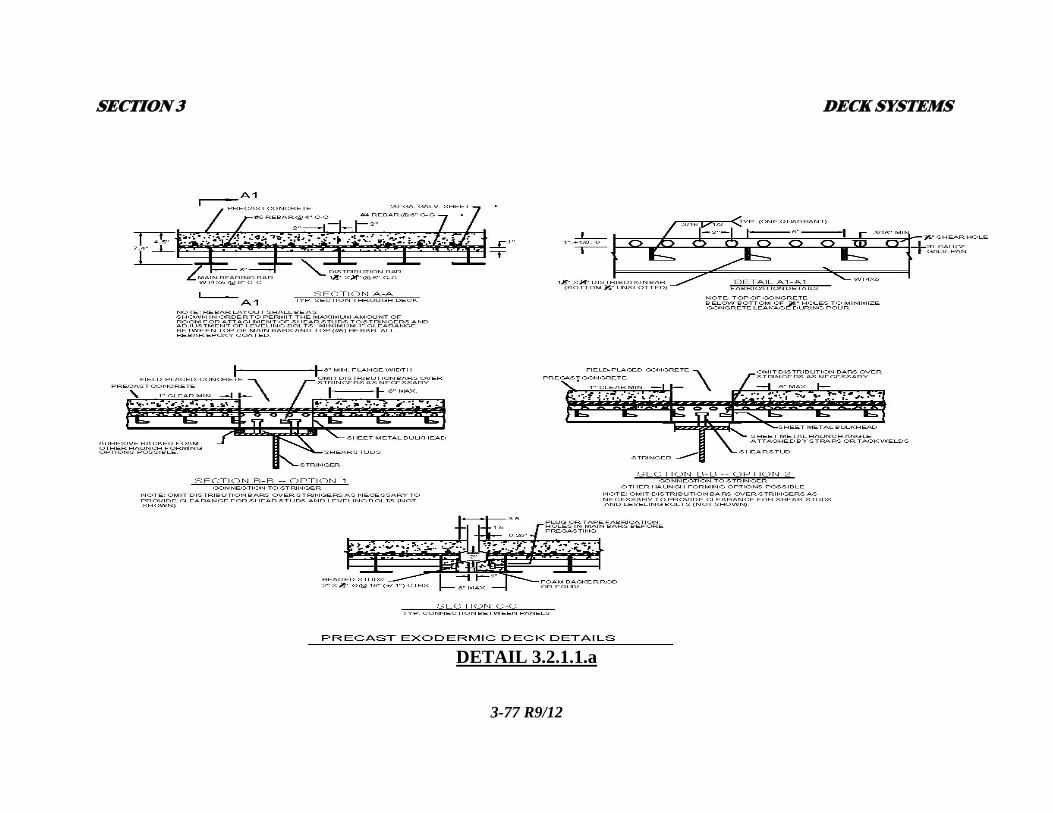
SECTION 3 DECK SYSTEMS
3-77 R9/12
DETAIL 3.2.1.1.a
SECTION 3
3-78 R9/12
DETAIL 3.2.1.1.b
U3.2.1.2 - EXODERMIC DECK DESIGN
DECK SYSTEMS

SECTION 3 DECK SYSTEMS
3-79 R9/12
A design manual is available from the Exodermic Bridge Deck Institute. The design methodology
and criteria for both the AASHTO 17th Edition and AASHTO LRFD 5th Edition are included on
the following pages.
The Designer has a number of choices to make in choosing an Exodermic deck configuration:
Main bar type and spacing, rebar size and spacing, and concrete thickness. A number of
Exodermic decks have used a 4 ½” concrete thickness in order to provide a standard 2 3/8” of
cover over rebar. Achieving desired total deck thickness and weight may require reducing the
concrete thickness. Exodermic decks have been constructed with concrete thickness of 3 inches to
5 inches. Lightweight concrete can be specified where weight is especially critical.
While any steel grid can be used in constructing an Exodermic deck, use of industry standard grid
configurations is advised to avoid costs associated with new tooling. The standard types are referred
to by the type of main bearing bar employed. Standard spacing of main bearing bars and
configuration of other components are given in tables available from the Exodermic Bridge Deck
Institute.

SECTION 3 DECK SYSTEMS
3-80 R9/12

SECTION 3 DECK SYSTEMS
3-81 R9/12

SECTION 3 DECK SYSTEMS
3-82 R9/12

SECTION 3 DECK SYSTEMS
3-83 R9/12

SECTION 3 DECK SYSTEMS
3-84 R9/12
Choice of main bearing bar type is generally determined by desired total deck thickness. Where
there are no deck thickness constraints, the 5.2 inch grid main bearing bars are the most efficient.
Depending on span, the 3 inch "T" grid should provide the lightest (and least expensive) option, as
the amount of full depth concrete over supports, and the full depth transverse joint between panels is
minimized. On the following sheets are example Exodermic deck sections as well as Table 3.2.1.3
the designer can use as a tool in determining various component sizes. The use of a proposed section
should always be verified with the completion of design calculations.
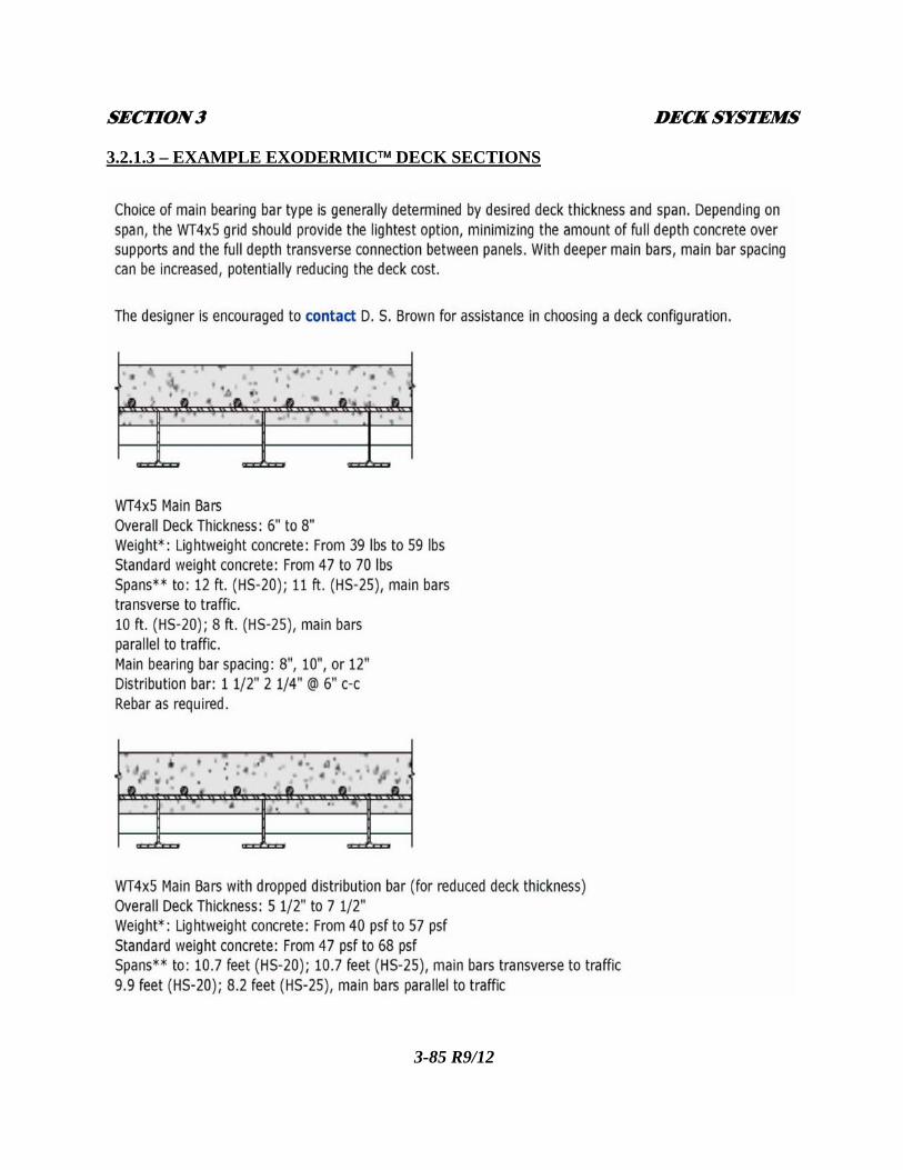
SECTION 3 DECK SYSTEMS
3-85 R9/12
3.2.1.3 – EXAMPLE EXODERMIC DECK SECTIONS

SECTION 3 DECK SYSTEMS
3-86 R9/12
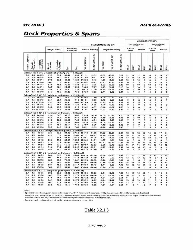
SECTION 3 DECK SYSTEMS
3-87 R9/12
Table 3.2.1.3

SECTION 3 DECK SYSTEMS
3-88 R9/12
3.2.2 - INVERSET™ BRIDGE SYSTEM
Inverset deck systems shall only be used with approval from the DSD. Inverset is a prefabricated
concrete and steel composite bridge superstructure system. The system utilizes a unique upside-
down casting method that uses the force of gravity to prestress steel beams. The typical bridge
superstructure is created using a series of panels, either longitudinally or transversely.
3.2.2.1 - OVERVIEW OF THE INVERSET™ BRIDGE SYSTEM
A typical unit consists of two beams made composite with a concrete deck. Each Inverset module
is manufactured with relatively short overhangs (usually 18 inches or less) to promote an efficient
slab design and to facilitate load transfer. The units are connected by a series of field-installed steel
diaphragms that distribute load to adjacent units. Joints between units are filled with non-shrink
grout and/or elastomeric concrete to prevent leakage.
3.2.2.2 - CHARACTERISTICS OF THE INVERSET™ BRIDGE SYSTEM
The primary advantages to using the Inverset Bridge System are:
A. Each unit is inherently stable and is essentially ready for use upon erection. If
required, a traffic stoppage to set an Inverset unit takes approx. 15 minutes.
B. Due to the modular nature of the prefabricated units, an entire bridge superstructure
can be manufactured "off-site" and be ready for installation prior to closing a bridge
for rehabilitation.

SECTION 3 DECK SYSTEMS
3-89 R9/12
C. Installation of Inverset superstructure modules is not temperature sensitive. Units
have been installed in sub-freezing weather
D. Inverset bridge modules are manufactured under plant controlled conditions with a
minimum design concrete strength of 5,000 psi. Casting the deck upside-down
provides a deck with its best quality concrete at the wearing surface. Additionally,
due to precompression in the concrete deck, deck cracking is minimized.
The Inverset bridge system can be used either longitudinally or transversely. See Detail 3.2.2.
Used longitudinally, Inverset units are designed and erected as the main superstructure elements.
Typical longitudinal Inverset uses are:
A. Simple span elements up to 100 feet on single span bridges;
B. Erected as simple span elements up to 100 feet on multiple span bridges and
subsequently made continuous over one or more supports;
C. Erected as one unit that is continuous over one or more supports (up to 100 feet
overall span);
D. Simple span elements spanning between transverse floor beams on long-span trusses
or girders.

SECTION 3 DECK SYSTEMS
3-90 R9/12
INVERSET™ BRIDGE SYSTEM DETAILS
DETAIL 3.2.2
SECTION 3
Transverse Inverset
DECK SYSTEMS
3-91 R9/12
plate girders or trusses. The units can be
structural m
span through trusses; long girder spans; and curved
U3.2.2.3 - DESIGN OF THE INVERSET™ BRIDGE SYSTEM
units are supported by other main structural members, typically longitudinal
made composite (or non-composite) with the main
embers. Typical uses for transverse Inverset units are: long span deck trusses; long
decks supported by straight girders or trusses.
Inverset
either
Applicable sections of these references are us
stresses, shear stud requirem
bridges are designed using standard composite construction design methodology using
AASHTO specification, supplemented by the NYSDOT Blue Pages and this manual.
ed to determine live load distribution, allowable
ents, etc.
A. Design Considerations:
1. Width of Units: 8 feet to 12 feet (Due to shipping constraints)
2. Deflection: Highway Only L/1000
Pedestrian Traffic L/1000
3. Live Load: Highway: HS-20, HS-25, or 1.25x(HL-93)
Railroad: Cooper E-80
4. Impact: As per AASHTO specifications
B. Design Methodology:
1. Allowable Stress Design 2. Load Factor Design 3. Load and Resistance Factor Design (LRFD)
SECTION 3 DECK SYSTEMS
3-92 R9/12
Structure dead load is carried by the composite superstructure, unlike conventional cast-in-place
design. Superimposed dead loads are distributed to the composite superstructure in the same manner
as conventional composite construction. Highway live loads are distributed across the bridge using
the guidelines set forth in AASHTO 17th Edition Table 3.23.1, "Concrete on Steel I-Beam
Stringers". The wheel load distribution is S/1.676 where (S) is taken as the average stringer spacing
in meters. Grid analysis and product testing have proven that the S/1.676 distribution with the
average stringer spacing is conservative.
The standard deck thickness including an integral wearing surface for an Inverset deck is 7 ½”.
Reinforcement cover is 2 ½” for the top mat and 1 inch for the bottom mat. Reinforcement is
designed in accordance with the AASHTO 17th Edition requirements for concrete bridge decks.
Virtually any bridge that can be built by conventional composite construction can be built with
Inverset superstructure modules. Practical limitations on shipping restrict piece sizes to
approximately 100 feet long and 75 tons. Shipping width should also be considered. The following
features can be built into Inverset units: skews; horizontal curves; width transitions; vertical
curves; superelevated decks; superelevation transitions; crowns; staged construction; rail systems;
and utilities.
SECTION 3 DECK SYSTEMS
3-93 R9/12
By using a family of geometric shapes, the horizontal geometry of most bridges can be
accommodated. Because the form is "hung" from the beams and the beams are set at their bearing
elevations, most any superelevation or superelevation transition can be manufactured. A crown is
easily achieved by placing the crown line along a joint. If this is not possible, a crown can be built
into an individual unit. Cambering the beams the appropriate amount so that the beam is parallel to
the grade accommodates crest vertical curves. Sag vertical curves are achieved using variable depth
haunches.
When designing an Inverset bridge carrying utilities, it is important to determine the section widths
so that utilities fall between the beams of a unit and the respective diaphragms and not in the area of
the field-installed diaphragms. The beams should also be deeper than the utility conduit.
Inverset can be manufactured with an integral wearing surface or smooth to accept a waterproofing
membrane and asphalt overlay. Integral wearing surfaces are made by casting the deck against a
form liner to produce a roughened surface. If longitudinal saw grooves are required, it is
recommended that they be cut in the field once all the units are in place and grouted. If an overlay is
used, a waterproofing membrane is applied to the deck once all the units are erected and the joints
are grouted. After that, an asphalt wearing course is applied. Because the deck can be manufactured
to meet the exact design deck, no truing and leveling course is required. While there is almost no
vertical movement at the joint, small rotations and shrinkage can cause cracking in rigid overlays.
For this reason, rigid overlays are not recommended. Joints are filled with grout for sealing purposes

SECTION 3 DECK SYSTEMS
3-94 R9/12
only and are not intended for load transfer to adjacent units. When constructing a bridge without an
overlay, the joints are filled with non-shrink grout to within 1 inch of the top of the joint. Once this
grout sets, the remaining 1 inch is filled with elastomeric concrete to seal the joint. If an overlay is
used, the entire joint is filled with non-shrink grout.
3.3 - CONCRETE SEALANTS APPLIED TO STRUCTURAL DECKS
Concrete sealant shall be applied to all exposed cement concrete surfaces of structural decks except
the underside between fascia drip edges. Thruway approved concrete sealants come in two types;
clear penetrating sealer, and solid color protective sealer. Approved item numbers for sealants can be
found on the Structures Estimate Template found in ProjectWise.
3.3.1 – DRIVING AND SIDEWALK SURFACES
Clear penetrating sealer shall be used on the surface of all cement concrete driving and sidewalk
surfaces. No sealer shall be applied to cement concrete surfaces that are covered with an asphalt
concrete overlay.
3.3.2 – FASCIA SURFACES
Fascia surfaces, which extend from the face-of-rail on the top of the deck/sidewalk, over the side to
the drip edge on the underside of the deck, shall be protected with a concrete sealant. On existing
structures, the proposed sealant type used shall match the existing on the structure (solid or clear).
Where no previous sealer has been used, clear penetrating sealer shall be applied. On new structures,

SECTION 3 DECK SYSTEMS
3-95 R9/12
clear penetrating sealer shall be used unless solid protective sealer is requested by the DBE.
3.4 - STAGE CONSTRUCTION
Stage Construction is a method used to replace bridge decks, superstructures, or entire bridges when
one or more travel lanes must remain in service throughout construction. The use of stage
construction will result in one or more longitudinal joints in the deck and therefore is not the
preferred method of construction. The designer should make every effort to close the structure
during construction and employ the use of offsite detours or crossovers wherever possible. See
Details 3.4.a and 3.4.b.

SECTION 3 DECK SYSTEMS
3-96 R9/12

SEC
TIO
N 3
DE
CK
SYST
EM
S
3-97 R9/12

SECTION 3 DECK SYSTEMS
3-98 R9/12
3.4.1 - GUIDELINES FOR STAGE CONSTRUCTION OF DECK SLABS ON STEEL
STRINGERS
The following guidelines will help to ensure that steel stringers placed under stage construction will
deflect properly under dead load and that the desired bridge deck cross slope will result.
A. The minimum number of girders within a construction phase that will support live loading is
3. This requirement provides structural redundancy under live load as well as provides a
more rigid structure that is less apt to twist under eccentric loading. This requirement may be
waived (reduced to 2 girders) by the DSD for the replacement of an existing structure if
traffic requirements preclude the use of 3 girders.
Separate computations for deflections due to dead load and superimposed dead load should
be made for each stage of construction. In addition, the slab and temporary overhangs
should be analyzed for the barrier and live load condition that will occur during each stage.
Details should be added to the plans with a note stating that the slab and slab overhang for
each stage has been designed for the loading conditions shown in the details.
B. If at all possible, use a third (closure) pour approximately 2.5 feet wide within the middle
portion of a bay between stages. Placing the closure pour in this positive moment area of the
deck between girders will assist in keeping the longitudinal joints tight throughout the life of
the structure. The closure pour will help to isolate the main second stage deck slab during the
curing process from undesirable vibrations caused by traffic on the first stage deck. In
addition, the closure pour permits a smooth transition between the top surfaces of the main
deck pours should there be any vertical misalignment between stages due to differential
SECTION 3 DECK SYSTEMS
3-99 R9/12
deflection between groups of stringers. If the closure pour cannot be made wide enough to
accommodate the transverse bar splice, and if deflections are expected to be small,
consideration should be given to the use of mechanical couplers on the transverse
reinforcement. If specified, the cost of furnishing and placing the mechanical couplers
should be included in the engineer's estimate for the reinforcing steel item. The practice of
bending up transverse reinforcement in restricted stage construction situations, then
rebending them down shall not be allowed. It is difficult to realign the bars properly, and the
coating is damaged. Similarly, the practice of welding transverse reinforcement should be
avoided, due to the cost of welding and repairing the resulting damage to bar coatings.
C. Transverse intermediate diaphragms and cross frames in the bay between stages shall not be
installed until the second stage deck slab has been in place for at least 72 hours, or they may
be installed by connecting at one end only. If a closure pour is used, those diaphragms in the
bay below the closure pour shall be installed (or connected at both ends) before the closure
pour is placed. Diaphragm fit-up misalignments due to differential girder deflection between
stages have been a typical problem of stage construction. For this reason, the details shall
require field drilling of the connection holes in either the diaphragm or connection plate, or
both, at one end of the diaphragm to avoid this problem.
D. Finally, top struts shall be included in the configuration of diaphragms in both bays adjacent
to the closure pour if cross frame type diaphragms are used. These top struts assist the
diaphragm in resisting rotation of the interim fascia girders.

SECTION 3 DECK SYSTEMS
3-100 R9/12
3.4.2 - GUIDELINES FOR STAGE CONSTRUCTION OF DECK SLABS ON
PRESTRESSED CONCRETE BEAMS
The following guidelines will help to ensure that prestressed beams placed under stage construction
will result in the desired bridge deck thickness, cross slope and vertical alignment of transverse
tendon holes due to proper beam deflection and long term camber growth of Stage II beams.
A. Separate computations for deflections and stresses due to dead load and superimposed dead load
should be made for each stage of construction.
B. Typically all prestressed beams for a structure are cast within a few days of each other. For
stage construction, the Stage II beams are left in storage while the Stage I beams are installed
and the remaining Stage I construction is completed. Due to creep and the differential loading
history between the Stage I and Stage II beams, the Stage II beams will have more upward
camber than the Stage I beams, at the time of Stage II beam installation. This results in a thinner
Stage II deck and possible misalignment of transverse tendon holes. If the anticipated
differential camber will exceed ½”:
a. Maintain a minimum 6 inches thick Stage II deck by either; designing and detailing a
thicker Stage I deck; or installing the Stage II beams at a lower elevation.
b. Alter the vertical placement of the transverse tendon holes for either Stage I or Stage
II beams to maintain their differential alignment to within ½”.
For estimating the projected camber growth (Time Dependent), use 50% of the transfer camber
SECTION 3 DECK SYSTEMS
3-101 R9/12
(without creep correction) for this value.
Example: Camber at transfer (w/o creep) = 12 inches.
Anticipated camber growth = .5 x 12 inches = 6 inches.
C. The same number of transverse tendons shall be used for the construction of each stage as
required for the final condition.
D. The transverse tendons shall not be spliced, but shall be continuous across the entire width of
adjacent beams for each stage. This may result in larger diaphragms to accommodate
multiple transverse tendons at each diaphragm for Stage I beams. The beams shall be
designed for this additional load.
E. All shear keys between Stage II beams as well as the shear key between Stage I and Stage II
beams should be filled prior to Stage II transverse tendon installation.
F. If at all possible, use a third (closure) pour between the main pours. The closure pour should
be approximately 2.5 feet wide and centered over a beam's edge. This will help to isolate the
main second stage deck slab during the curing process from undesirable vibrations caused by
traffic on the first stage deck. In addition, the closure pour permits a smooth transition
between the top surfaces of the main deck pours should they be misaligned due to improper
deflection or camber of one or both groups of beams.
G. Wait a minimum of 72 hours following completion of the first stage deck pour before
beginning the second stage pour. Wait a minimum of 72 hours following completion of the
second stage deck pour before beginning the closure pours.
SECTION 3 DECK SYSTEMS
3-102 R9/12
3.5 - SHOULDER TREATMENT
Thruway Mainline, ramp, and overhead bridges shall incorporate either a straight run-off with four
rail bridge rail; or two rail bridge rail with curbing, four rail bridge rail with sidewalk, concrete
parapet with sidewalk, or concrete barrier to contain and direct drainage off the structure (at the ends
of the bridge or at scuppers). Curbs shall only be used for the two rail bridge rail application or
when sidewalks are required. Refer to Subsection 3.1.4.1 – Thruway Rail/Barrier and Overhang
Design Policy for guidance on the appropriate rail/barrier system to use.
3.6 - BRIDGE DECK DRAINAGE Structures that have curbs, sidewalks, or barrier preventing drainage off the side of the deck shall be
analyzed to ensure that ponding of water, which could create traffic safety problems (such as hydro-
planing), does not occur. The following design criteria shall be used on all structures (overheads and
mainlines) which do not use curbless details.
A. The puddle width shall be restricted to the shoulder.
B. Maximum puddle depth shall not exceed 2 inches.
C. The design is to be based on the rainfall intensity of the most severe storm. See Table
3.6 on next page for rainfall intensity data.
See Appendix C for typical drainage and scupper details. The designer is encouraged to review the
FHWA HEC 21 - Design of Bridge Deck Drainage, dated May 1993 @:
http://www.fhwa.dot.gov/bridge/hec21.pdf

SECTION 3 DECK SYSTEMS
3-103 R9/12
Rainfall Intensity Data for Bridges within the Thruway Corridor
Intensity (in/hr)
Intensity (in/hr)
Location 5min storm/ 2 year event
5min storm/ 10 year event
Thruway Limits for Location Use
NYC (Manhattan)
4.998 6.418 0.00 to MP 16, including I-95
Peekskill 4.786 6.224 MP 16 to MP 60, including I-84 Poughkeepsie 4.66 6.097 MP 60 to 100 Catskill 4.577 5.992 MP 100 to MP 140, including
Berkshire Spur Albany 4.393 5.724 MP 140 to MP 170 Canajoharie 4.16 5.402 MP 170 to MP 210 Utica 4.091 5.303 MP 210 to MP 250 Syracuse 4.162 5.386 MP 250 to MP 330 Rochester 4.145 5.376 MP 330 to MP 410 Buffalo 4.219 5.469 MP 410 to MP 440, including
Niagara Section Silver Creek 4.275 5.562 MP 440 to MP 470 Jamestown 4.39 5.724 MP 470 to MP 496 (Pennsylvania
Line)
Rainfall Intensity values taken from NYSDOT Scupper Program User Manual dated June 1999.
TABLE 3.6 Notes: 1) Due to Thruway policy of placing barrier on all mainline structures, the 5 min/10 year event shall be used on all mainline bridges. 2) For all overheads that use curbless details, the 5min/2 year rainfall intensity shall be used. 3) For all overheads that use barrier or curb, are less than 330 feet in length and have a vertical curve located in the general vicinity of middle of the bridge, the 5min/2yr rainfall intensity shall be used. 4) All other overheads that use barrier or curb which do not meet the criteria of note 3, shall use the 5min/10 year rainfall intensity event.

SECTION 3 DECK SYSTEMS
3-104 R9/12
3.7 - BRIDGE DECK ACCESS HOLES Deck access holes are 1 foot diameter holes through the deck in the vicinity of the fascia. On
mainline twin structures, where the distance between interior fascias is small (1 to 3 inches), these
holes provide access for welding leads, air hoses, electrical lines and paint hoses for future
maintenance. Mainline structures are typically very wide and so access from the outside fascias to
the interior can be very difficult if possible at all. On rehabilitation and replacement projects the
designer should consult with the Division Bridge Engineer to determine if and where deck access
holes should be located. Refer to Appendix C for details of deck access holes on page C6-7.