section: 23 05 23 00: general-duty chapter: 01 - yale .... valves in insulated piping: provide stem...
TRANSCRIPT

Title: YALE OFFICE OF FACILITIES PROCEDURE MANUAL
Chapter: 01 - Yale Design Standard
Division: HVAC Standards
Section: 23 05 23 00: General-Duty
Valves for Mechanical Systems
Date: 06/15/16
Author: Office of Facilities
CC: Project Folder
Page 1 of 16
Date Description of Change Pages / Sections Modified ID
6/15/16 Entire document - mgl44
PART 1 - INTRODUCTION
1.1 PURPOSE
A. This section is intended to define the general installation and minimum product
requirements for hydronic and steam valves.
PART 2 - GENERAL DESIGN REQUIREMENTS
2.1 GENERAL VALVE REQUIREMENTS
A. Refer to Service Index dated June 15, 2016 for valve types.
B. Valve Pressure and Temperature Ratings: Not less than indicated and as required for
system operating, maximum, and test pressures and temperatures.
C. Manual Valve Sizes: Same as upstream piping unless otherwise indicated.
D. Valve Actuator Types:
1. Gear Actuator: For quarter-turn valves with wheels NPS 6 and larger.
2. Hand wheel: Fastened to valve stem, for valves other than quarter turn.
3. Hand lever: For quarter-turn valves NPS 6 and smaller.
4. Wrench: For plug valves with square heads. Furnish Owner with 1 wrench for every
plug valve, for each size square plug-valve head.
5. Chain wheel: Device for attachment to valve hand wheel, stem, or other actuator; for
all valves installed 6 feet or higher above finished floor extend chains to an elevation
of 5 feet above finished floor. Chain shall be equipped with clasp and hook to secure
chain as not to be in the path of egress.
E. Valves in Insulated Piping: Provide stem extensions and the following features:
1. Gate Valves: With rising stem.
2. Ball Valves: With extended operating handle of non-thermal-conductive material,
and protective sleeve that allows operation of valve without breaking the vapor seal
or disturbing insulation.
3. Butterfly Valves: With extended neck.
F. Valve-End Connections:
1. Flanged: With flanges according to ASME B16.1 for iron valves.
2. Grooved: With grooves according to AWWA C606.
3. Solder Joint: With sockets according to ASME B16.18.
4. Threaded: With threads according to ASME B1.20.1.
5. Valve Bypass and Drain Connections: MSS SP-45.

Title: YALE OFFICE OF FACILITIES PROCEDURE MANUAL
Chapter: 01 - Yale Design Standard
Division: HVAC Standards
Section: 23 05 23 00: General-Duty
Valves for Mechanical Systems
Date: 06/15/16
Author: Office of Facilities
CC: Project Folder
Page 2 of 16
G. By-pass and Drain Connections: Isolation valves shall be provide with by-passes for
Pressure Reducing Stations (PRS) and other systems as directed by Yale. Comply with
MSS SP-45 bypass and drain connections.
H. Wet Tap/ Hot Tap Valves
1. Valves shall conform to the requirements of this and other applicable university
standards.
2.2 MANUAL VALVE DESIGNATION
A. This section includes the valve identification code, and Standard used in the Service Index.
1. Table 1: Valve Identification
Valve Designation Valve Type Standard
BA Ball Ball Valves
BF Butterfly Butterfly Valves
GA Gate Gate Valves
PL Plug Plug Valves
GL Globe Globe Valves
CK Check Check Valves
2.3 DESIGN DOCUMENT REQUIREMENTS
A. The design drawings shall include a riser and flow diagram and details of system
specialties for all HVAC systems. Collectively, the drawing elements shall capture and
illustrate all valve applications including: shut-off, balancing, bypass, control, direction
flow control, and drain valves.
B. The riser flow diagram shall include valve tags as identified in the university Service Index
and applicable Valve Standard.
C. Standard details, and plan view drawings shall include valves, and specialty items. Valves
and specialty items shall be tagged per university Service Index.
2.4 DESIGN SYSTEM REQUIREMENTS:
A. Where new piping connections are indicated to be connected to existing system, the
consultant shall confirm and indicate in the contract documents the location of existing
isolation valves. If there are no existing isolation valves to connect the new piping to

Title: YALE OFFICE OF FACILITIES PROCEDURE MANUAL
Chapter: 01 - Yale Design Standard
Division: HVAC Standards
Section: 23 05 23 00: General-Duty
Valves for Mechanical Systems
Date: 06/15/16
Author: Office of Facilities
CC: Project Folder
Page 3 of 16
existing piping without requiring a pipe freeze, wet, or hot tap the consultant shall identify
the scope of work in the contract documents. The scope of work shall identify the
following
1. Location of POC
2. System and equipment interruption and coordination shutdowns.
3. Type of tie-in procedure
4. Work associated with recommissioning existing system
B. Valve flange rating shall be compliant with system working, maximum and test pressure,
per ANSI pressure classification tables.
C. Within each building there shall be a building valve to isolate the service to the building.
D. Isolation valves shall be provided at all pumps, tanks, reducing and automatic or
mechanical flow control devices, radiation, coils and heat exchangers, and at all other
apparatus requiring partial drainage of the system for periodic maintenance or inspection.
The isolation valves shall be so located as to permit removal and/or service of the isolated
equipment without draining complete or substantial portions of the system. Except where
flanged valves are used, each connection to equipment shall be made with screwed or
flanged union on the equipment side of the valve.
E. Isolation valves shall be provided at all branch takeoffs from system mains and risers and
returns to system.
F. Check valves installed in the horizontal position shall be swing checks; valves installed in
the vertical position shall be silent checks, except that all check valves in pump discharges
shall be silent checks.
G. Strainers shall have isolation valves up and down stream of strainer, to avoid draining the
entire system or hydronic circuit the strainer serves.
H. Provide blow-down valves at all strainers, and pipe to drain.
I. Risers shall have drain valves installed at the low point to permit draining of supply and
return risers without impacting other system risers. Drain valves shall have approved ball
valve type hose bibs and caps.
J. Provide balancing valves in the branch lines of water systems where hydraulic disparities
between the branches may exist.
K. Provide isolation valves of water piping leaving MER's to permit repairs of MER

Title: YALE OFFICE OF FACILITIES PROCEDURE MANUAL
Chapter: 01 - Yale Design Standard
Division: HVAC Standards
Section: 23 05 23 00: General-Duty
Valves for Mechanical Systems
Date: 06/15/16
Author: Office of Facilities
CC: Project Folder
Page 4 of 16
equipment without draining the entire system.
L. High-performance butterfly valves shall be in the closed position during installation in the
piping systems. Leave all valves in the closed position at the completion of the installation.
2.5 MECHANICAL IDENTIFICATION REQUIREMENTS
A. Manual and control valves shall be labeled with 1-1/2" (one and one half inch) brass tags
bearing a letter to indicate the service and a number to indicate the valve. A permanent
valve chart and system schematic diagram shall show the location of all valves. Valve
Tags and schematic diagram names shall be coordinated with the final P&ID diagram.
B. Valves shall have the name of the manufacturer and the nominal size of the valve on the
body or bonnet or shown on a permanently attached plate in die-stamped letters.
2.6 INDUSTRY STANDARDS, CODE AND MANUFACTURE REQUIREMENTS
A. Valves for potable water service shall comply with the most current version NSF 61,
SDWA and shall not exceed the allowable content of lead.
B. Valves and flanges shall comply with applicable ANSI, AWWA, API, ASTM, ASME,
OSHA, and MSS requirements.
C. Valve installation shall be in accordance with manufacturer's recommendations.
PART 3 - MINIMUM PRODUCT CRITERIA
3.1 PRODUCT DATA SHEETS
See following Product Data Sheets.
Title: YALE OFFICE OF FACILITIES PROCEDURE MANUAL
Chapter: 01 - Yale Design Standard
Division: HVAC Standards
Section: 23 05 23 00: General-Duty
Valves for Mechanical Systems
Date: 06/15/16
Author: Office of Facilities
CC: Project Folder
Page 5 of 16
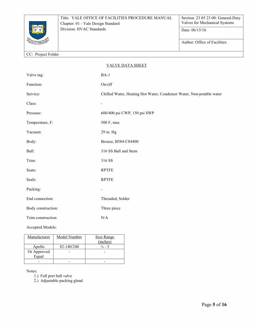
VALVE DATA SHEET
Valve tag: BA-1
Function : On/off
Service: Chilled Water, Heating Hot Water, Condenser Water, Non-potable water
Class: -
Pressure: 600/400 psi CWP, 150 psi SWP
Temperature, F: 500 F, max
Vacuum: 29 in. Hg
Body: Bronze, B584-C84400
Ball: 316 SS Ball and Stem
Trim: 316 SS
Seats: RPTFE
Seals: RPTFE
Packing: -
End connection: Threaded, Solder
Body construction: Three piece
Trim construction: N/A
Accepted Models:
Manufacturer Model Number Size Range
(inches)
Apollo 82-140/240 ¼ - 3
Or Approved
Equal
- -
- - -
Notes:
1.) Full port ball valve
2.) Adjustable packing gland

Title: YALE OFFICE OF FACILITIES PROCEDURE MANUAL
Chapter: 01 - Yale Design Standard
Division: HVAC Standards
Section: 23 05 23 00: General-Duty
Valves for Mechanical Systems
Date: 06/15/16
Author: Office of Facilities
CC: Project Folder
Page 6 of 16
VALVE DATA SHEET
Valve tag: BA-2
Function : On/off
Service: Steam: Low, Medium, High-Pressure, Steam Condensate gravity and
pumped
Class: Class 600: ¼ inch to 2 inch; Class 300 2-1/2 inch to 3 inch
Pressure: Refer to Service Index and Piping Standard for minimum requirements
Temperature, F: 500 F, max
Vacuum: 29 in. Hg
Body: ASTM A216 WCB
Ball: 316 SS (ball and stem)
Trim: -
Seats: TFM
Seals: Graphite (Body)
Packing: NOVA
End connection: Threaded, Socket, Butt, Class 300 and 600 Flange (match to valve).
Body construction: Three piece
Trim construction: N/A
Accepted Models:
Manufacturer Model Number Size Range
Sharpe Series 84 ¼ to 3
Or Approved
Equal
- -
- - -
Notes:
1.) Shall be full port ball valve
2.) Condensate valves shall accommodate schedule-80 pipe.
VALVE DATA SHEET

Title: YALE OFFICE OF FACILITIES PROCEDURE MANUAL
Chapter: 01 - Yale Design Standard
Division: HVAC Standards
Section: 23 05 23 00: General-Duty
Valves for Mechanical Systems
Date: 06/15/16
Author: Office of Facilities
CC: Project Folder
Page 7 of 16
Valve tag: BA-3
Function : On/off
Service: Potable, Well, and Tempered Water
Pressure: 600 psi CWP, 150 psi SWP
Temperature, F: 400 F, max
Vacuum: 29 in. Hg
Body: Lead Free Brass, C27451
Ball: LF Brass < 4 inch, SS 4 inch
Trim: Lead Free
Seats: RPTFE
Seals: -
Packing: RPTFE
End connection: NPT, Solder
Body construction: Two piece
Trim construction: N/A
Accepted Models:
Manufacturer Figure Number Size Range
Apollo 77LFL-100/200 1/4 .. 4 inch
Or Approved
Equal
- -
- - -
Notes:
1. Full ported valves
VALVE DATA SHEET

Title: YALE OFFICE OF FACILITIES PROCEDURE MANUAL
Chapter: 01 - Yale Design Standard
Division: HVAC Standards
Section: 23 05 23 00: General-Duty
Valves for Mechanical Systems
Date: 06/15/16
Author: Office of Facilities
CC: Project Folder
Page 8 of 16
Valve tag: BA-4
Function : On/off
Service: City Potable Water (Service Entrance)
Pressure: 600/400 psi CWP, 150 psi SWP
Temperature, F: 400 F, max
Vacuum: 29 in. Hg
Body: Bronze, Lead Free
Ball: Brass, Lead Free
Trim: -
Seats: RPTFE
Seals: RPTFE
Packing: MPTFE
End connection: NPT, Solder
Body construction: Three piece
Trim construction: N/A
Accepted Models:
Manufacturer Figure Number Size Range
Apollo 82LF-100/200 2-1/2” and less
Or Approved
Equal
- -
- - -
Notes:
1.) Full ported
Title: YALE OFFICE OF FACILITIES PROCEDURE MANUAL
Chapter: 01 - Yale Design Standard
Division: HVAC Standards
Section: 23 05 23 00: General-Duty
Valves for Mechanical Systems
Date: 06/15/16
Author: Office of Facilities
CC: Project Folder
Page 9 of 16
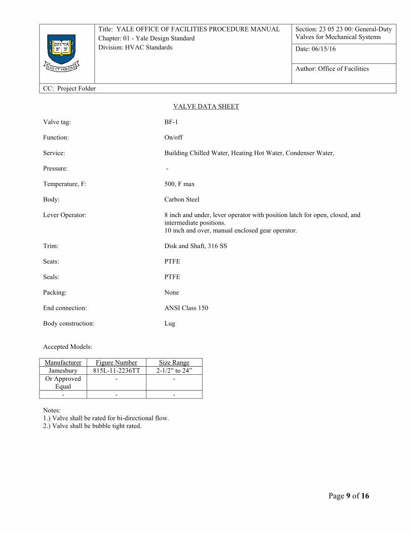
VALVE DATA SHEET
Valve tag: BF-1
Function : On/off
Service: Building Chilled Water, Heating Hot Water, Condenser Water,
Pressure: -
Temperature, F: 500, F max
Body: Carbon Steel
Lever Operator: 8 inch and under, lever operator with position latch for open, closed, and
intermediate positions.
10 inch and over, manual enclosed gear operator.
Trim: Disk and Shaft, 316 SS
Seats: PTFE
Seals: PTFE
Packing: None
End connection: ANSI Class 150
Body construction: Lug
Accepted Models:
Manufacturer Figure Number Size Range
Jamesbury 815L-11-2236TT 2-1/2” to 24”
Or Approved
Equal
- -
- - -
Notes:
1.) Valve shall be rated for bi-directional flow.
2.) Valve shall be bubble tight rated.

Title: YALE OFFICE OF FACILITIES PROCEDURE MANUAL
Chapter: 01 - Yale Design Standard
Division: HVAC Standards
Section: 23 05 23 00: General-Duty
Valves for Mechanical Systems
Date: 06/15/16
Author: Office of Facilities
CC: Project Folder
Page 10 of 16
VALVE DATA SHEET
Valve tag: BF-2
Function : On/off
Service: HPS, MPS, LPS, Plant Chilled Water
Pressure: -
Temperature, F: 500, F max
Body: -
Lever Operator: 8 inch and under, lever operator with position latch for open, closed, and
intermediate positions.
10 inch and over, manual enclosed gear operator.
Trim: -
Seats: -
Seals: -
Packing: None
End connection: -
Body construction: Lug
Accepted Models:
Manufacturer Figure Number Size Range
Velan TORQSEAL
M(XX)-1CP02-
DADA
2-1/2 – 24 Inch
Vanessa 30.000 SERIES 2-1/2 – 24 Inch
Quadax EQAL (0000)
BXBBFKXBBBB
BBXX7FXXXX
2-1/2 – 24 Inch
Notes:
1.) Valve shall be rated for bi-directional flow.
2.) Valve shall be bubble tight rated.
3.) Valve shall be triple-offset type.

Title: YALE OFFICE OF FACILITIES PROCEDURE MANUAL
Chapter: 01 - Yale Design Standard
Division: HVAC Standards
Section: 23 05 23 00: General-Duty
Valves for Mechanical Systems
Date: 06/15/16
Author: Office of Facilities
CC: Project Folder
Page 11 of 16
VALVE DATA SHEET
Valve tag: GA-3
Function : On/off
Service: Chilled Water, Glycol Chilled Water, Heating Hot Water, Low Pressure
Steam
Design pressure: 230 psig at 300 degrees F
Body: ASTM A216 WCB, cast steel
Bonnet: ASTM A216 WCB, cast steel
Trim: API 8
Seats: -
Seals: -
Packing: Graphite
End connection: Class 150, RF, Butt Weld
Body construction: Bolted bonnet, OS&Y
Trim construction: Screwed
Accepted Models:
Manufacturer Figure Number Size Range
Milwaukee 1550 / 1552 2” to 12”
Or Approved
Equal
- -
- - -
Notes:
1.) Low pressure steam not to exceed 15 psig
2.) Heating Hot Water not to exceed 240 F
3.) Glycol Chilled water, check fluid compatibility with valve material.
VALVE DATA SHEET
Valve tag: GA-4

Title: YALE OFFICE OF FACILITIES PROCEDURE MANUAL
Chapter: 01 - Yale Design Standard
Division: HVAC Standards
Section: 23 05 23 00: General-Duty
Valves for Mechanical Systems
Date: 06/15/16
Author: Office of Facilities
CC: Project Folder
Page 12 of 16
Function : On/off
Service: Medium Pressure Steam
Design pressure: 410 psig at 800 degrees F
Body: ASTM A216 WCB, cast steel
Bonnet: ASTM A216 WCB, cast steel
Trim: API 8
Seats: -
Seals: -
Packing: Graphite
End connection: Class 300, RF, Butt Weld
Body construction: Bolted bonnet, OS&Y
Trim construction: Screwed
Accepted Models:
Manufacturer Figure Number Size Range
Milwaukee 3050 / 3052 2” to 12”
Or Approved
Equal
- -
- - -
VALVE DATA SHEET
Valve tag: GA-5
Function : On/off

Title: YALE OFFICE OF FACILITIES PROCEDURE MANUAL
Chapter: 01 - Yale Design Standard
Division: HVAC Standards
Section: 23 05 23 00: General-Duty
Valves for Mechanical Systems
Date: 06/15/16
Author: Office of Facilities
CC: Project Folder
Page 13 of 16
Service: High Pressure Steam
Design pressure: 825 psig at 800 degrees F
Body: ASTM A2116 WCB, cast steel
Bonnet: ASTM A2116 WCB, cast steel
Trim: API 8
Seats: -
Seals: -
Packing: Graphite
End connection: Class 600, RF, Butt Weld
Body construction: Bolted bonnet, OS&Y
Trim construction: Screwed
Accepted Models:
Manufacturer Figure Number Size Range
Milwaukee 6050 / 6053 2” to 12”
Or Approved
Equal
- -
- - -
Notes:
VALVE DATA SHEET
Valve tag: GL-1
Function : Throttling
Service: High Pressure Steam

Title: YALE OFFICE OF FACILITIES PROCEDURE MANUAL
Chapter: 01 - Yale Design Standard
Division: HVAC Standards
Section: 23 05 23 00: General-Duty
Valves for Mechanical Systems
Date: 06/15/16
Author: Office of Facilities
CC: Project Folder
Page 14 of 16
Design pressure: 825 psig at 800 degrees F
Body: ASTM A2116 WCB, cast steel
Bonnet: ASTM A2116 WCB, cast steel
Trim: API 8
Seats: -
Seals: -
Packing: Graphite
End connection: Class 600, RF, Butt Weld
Body construction: Bolted bonnet, OS&Y
Trim construction: Screwed
Accepted Models:
Manufacturer Figure Number Size Range
Milwaukee 6050 / 6053 2” to 12”
Or Approved
Equal
- -
- - -
Notes:
1.) Shall be Class IV valve or higher
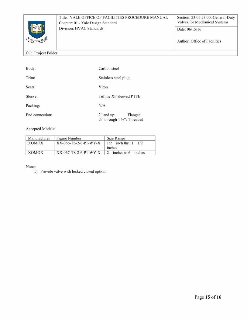
VALVE DATA SHEET
Valve tag: PL-1
Function : On/Off
Service: No. 2 fuel oil
Design pressure: 125 psi at 100 degrees F
Title: YALE OFFICE OF FACILITIES PROCEDURE MANUAL
Chapter: 01 - Yale Design Standard
Division: HVAC Standards
Section: 23 05 23 00: General-Duty
Valves for Mechanical Systems
Date: 06/15/16
Author: Office of Facilities
CC: Project Folder
Page 15 of 16
Body: Carbon steel
Trim: Stainless steel plug
Seats: Viton
Sleeve: Tufline XP sleeved PTFE
Packing: N/A
End connection: 2” and up: Flanged
½” through 1 ½”: Threaded
Accepted Models:
Manufacturer Figure Number Size Range
XOMOX XX-066-TS-2-6-P1-WY-X 1/2 inch thru 1 1/2 inches
XOMOX XX-067-TS-2-6-P1-WY-X 2 inches to 6 inches
Notes:
1.) Provide valve with locked closed option.
Title: YALE OFFICE OF FACILITIES PROCEDURE MANUAL
Chapter: 01 - Yale Design Standard
Division: HVAC Standards
Section: 23 05 23 00: General-Duty
Valves for Mechanical Systems
Date: 06/15/16
Author: Office of Facilities
CC: Project Folder
Page 16 of 16
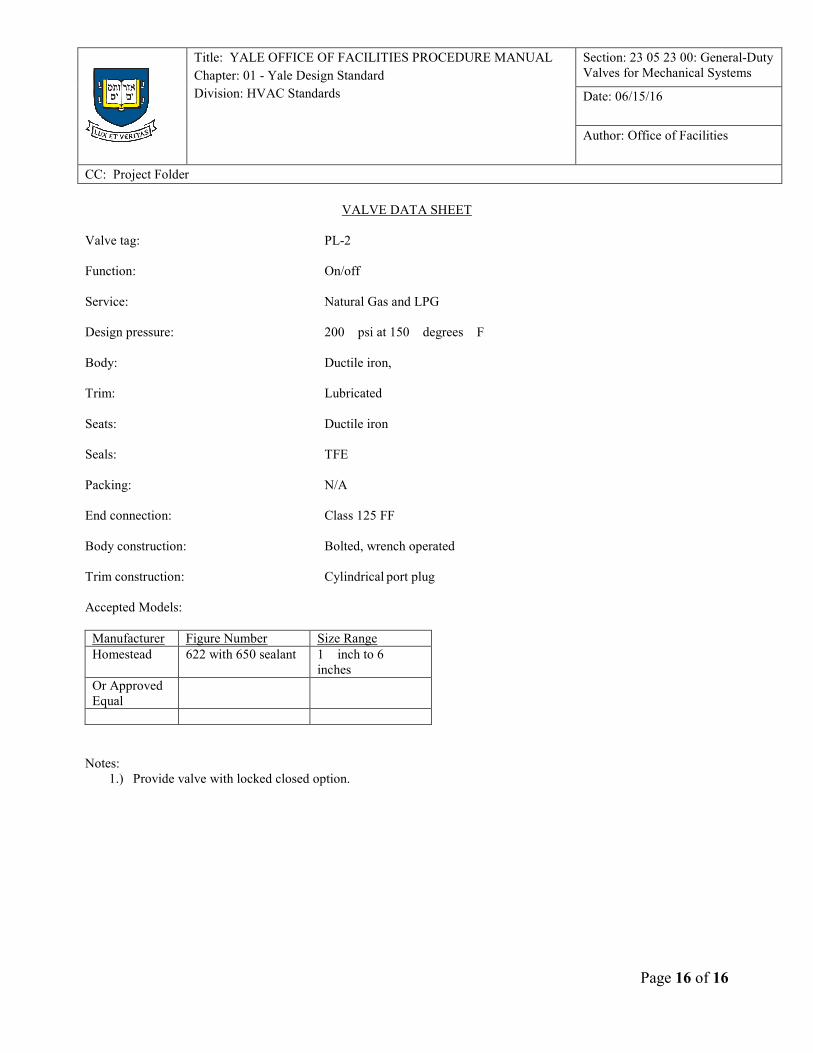
VALVE DATA SHEET
Valve tag: PL-2
Function: On/off
Service: Natural Gas and LPG
Design pressure: 200 psi at 150 degrees F
Body: Ductile iron,
Trim: Lubricated
Seats: Ductile iron
Seals: TFE
Packing: N/A
End connection: Class 125 FF
Body construction: Bolted, wrench operated
Trim construction: Cylindrical port plug
Accepted Models:
Manufacturer Figure Number Size Range
Homestead 622 with 650 sealant 1 inch to 6 inches
Or Approved
Equal
Notes:
1.) Provide valve with locked closed option.