section 17 - soil reinforced concrete structure interaction systems
TRANSCRIPT

BRIDGE DESIGN SPECIFICATIONS • APRIL 2000
SECTION 17 - SOIL REINFORCED CONCRETE STRUCTURE INTERACTION SYSTEMS
17.1 GENERAL
17.1.1 Scope
Specifications in this section govern the design of buried reinforced concrete structures. A buried reinforced concrete element becomes part of a composite system comprising the reinforced concrete section and the soil envelope, both of which contribute to the structural behavior of the system.
17.1.2 Notations
A = effective tension area, in square inches, of concrete surrounding the flexural tension reinforcement and having the same centroid as that reinforcement, divided by the number of bars or wires. When the flexural reinforcement consists of several bar sizes or wire sizes, the number of bars or wires shall be computed as the total area of reinforcement divided by the area of the largest bar or wire used. (Articles 17.6.4 and 17.7.4)
AP = total active lateral pressure acting on pipe, lbs/ft (Figure 17.4G)
As = tension reinforcement area on width b, in.2/ft. (Articles 17.4.6.6, 17.6.4.7, 17.7.4.7 and 17.8.5.7)
Asi = total area of inner cage reinforcement required in length b, in.2/ft (Article 17.4.6.6)
Aso = total area of outer cage reinforcement required in length b, in.2/ft (Article 17.4.6.6)
Avr = stirrup reinforcement area to resist radial tension forces on width b, in.2/ft. in each line of stirrups at circumferential spacing s (Article 17.4.6.6.6.1)
Avs = required area of stirrups for shear reinforcement, in.2 (Article 17.4.6.6.6.2)
+ Awa = actual steel area of the individual circumfer+ ential wire, in.2 (Article 17.4.7)
Awr = steel area required for an individual circumferential wire for flexure at a splice or at the
point of maximum moment for quadrant mat reinforcement, in.2 (Article 17.4.7)
b = width of section which resists M, N, V— Usually b = 12 inches (Article 17.4.6)
Bc = out-to-out horizontal span of pipe, or box, ft (Articles 17.4.4 and 17.4.5)
Bf = bedding factor (Article 17.4.5) Bfe = earth load bedding factor BfLL = live load bedding factor Bl = crack control coefficient for effect of cover
and spacing of reinforcement (Article 17.4.6)
cB¢ = out-to-out vertical rise of pipe, ft (Figure 17.4G)
CA = constant corresponding to the shape of pipe (Article 17.4.5)
CN = parameter which is a function of the distribution of the vertical load and the vertical reaction (Article 17.4.5)
Cl = crack control coefficient for type of reinforcement (Article 17.4.6)
d = distance from compression face to centroid of tension reinforcement, in.(Articles 17.4.6.6, 17.6.4.7, 17.7.4.7 and 17.8.5.7)
db = diameter of reinforcing wire or bar, in. (Article 17.4.7)
dc = thickness of concrete cover measured from extreme tension fiber to center of bar or wire located closest thereto (Articles 17.6.4 and 17.7.4)
D = D-load of pipe, three-edge bearing test load expressed in pounds per linear foot per foot of span to produce a 0.01-inch crack (Article 17.4.5)
Di = inside diameter of pipe, in. fs = maximum allowable service load stress in the
reinforcing steel for crack control (Articles 17.6.4.7, 17.7.4.7 and 17.8.5.7)
fss = actual service load stress in reinforcing steel (Articles 17.6.4.7, 17.7.4.7 and 17.8.5.7)
fv = maximum allowable strength of stirrup material, lbs./in.2 (Article 17.4.6.6.6)
fy = specified yield strength of reinforcement, lbs./in.2 (Article 17.4.6)
+ +
SECTION 17 SOIL-REINFORCED CONCRETE STRUCTURE INTERACTION SYSTEMS 17-1

BRIDGE DESIGN SPECIFICATIONS • APRIL 2000
Fc = factor for effect of curvature on diagonal tension (shear) strength in curved compo- Ns = nents (Article 17.4.6.6.5)
Fcr = factor for adjusting crack control relative to average maximum crack width of 0.01 inch when Fcr = 1.0 (Article 17.4.6.6.4) Nu =
Fd = factor for crack depth effect resulting in increase in diagonal tension (shear) strength p = with decreasing d (Article 17.4.6.6.5) PL =
Fe = soil-structure interaction factor (Article 17.4.4)
Frp = factor for process and local materials that q = affect the radial tension strength of pipe (Article 17.4.6) rs =
Frt = factor for pipe size effect on radial tension strength (Article 17.4.6.6.3) sv =
Fvp = factor for process and local materials that affect the shear strength of pipe (Article s� = 17.4.6.6.5)
FN = coefficient for effect of thrust on shear strength Si = (Article 17.4.6.6.5)
cf ¢ = design compressive strength of concrete, lbs./ tb = in.2 (Articles 17.4.6, 17.6.2, and 17.7.2)
h = overall thickness of member (wall thickness), Vb = in. (Articles 17.4.6.6, 17.6.4.7, 17.7.4.7 and 17.8.5.7) Vc =
H = height of fill above top of pipe, ft. (Articles 17.4.4 and 17.4.5)
HAF = horizontal arching factor (Figure 17.4A) Vu = i = coefficient for effect of axial force at service
load stress, fs (Articles 17.4.6.6.4, 17.6.4.7, Vuc = 17.7.4.7 and 17.8.5.7)
j = coefficient for moment arm at service load VAF = stress, fs (Articles 17.4.6.6.4, 17.6.4.7, 17.7.4.7 w = and 17.8.5.7)
K = ratio of the active unit lateral soil pressure to WE = unit veritcal soil pressure - Rankine’s coefficient of active earth pressure (Figure 17.4G) Wf =
Ld = development length of reinforcing wire or bar, in (Article 17.4.7) WL =
Mnu = factored moment acting on length b as modified for effects of compressive or tensile thrust, WT = in-lbs/ft (Article 17.4.6)
Ms = moment acting on cross section of width, b, x = service load conditions, in.-lbs/ft (taken as absolute value in design equations, always +) (Articles 17.4.6.6.4, 17.6.4.7, 17.7.4.7 and Y = 17.8.5.7)
Mu = factored moment acting on cross section of width b, in.-lbs./ft. (Article 17.4.6.6) r =
n = number of layers of reinforcement in a cage
1 or 2 (Article 17.4.6) axial thrust acting on cross section of width b, service load condition (+ when compressive, - when tensile) lbs./ft. (Articles 17.4.6.6.4, 17.6.4.7, 17.7.4.7 and 17.8.5.7)) factored axial thrust acting on cross section of width b, lbs./ft. (Article 17.4.6) projection ratio (Article 17.4.5.2) PL denotes the prism load (weight of the column of earth) over the pipe’s outside diameter, lbs/ft ratio of the total lateral pressure to the total vertical load (Article 17.4.5) radius of the inside reinforcement, in.(Article 17.4.6.6.3.1) circumferential spacing of stirrups, in. (Article 17.4.6.6.6) spacing of circumferential reinforcement, in. (Articles 17.4.6.6.4 and 17.4.7) internal horizontal span of pipe, in. (Articles 17.4.5 and 17.4.6) clear cover over reinforcement, in. (Article 17.4.6) basic shear strength of critical section, lbs./ft. where Mnu/Vud = 3.0 (Article 17.4.6.6.5) nominal shear strength provided by width b, of concrete cross section, lbs./ft. (Article 17.4.6) factored shear force acting on cross section of width b, lbs./ft. (Article 17.4.6) factored shear force at critical section, lbs./ft. where Mnu/Vud = 3.0 (Article 17.4.6.6.5) vertical arching factor (Article 17.4.4.2.1.1) unit weight of soil, lbs per cubic foot (Article 17.4.4) total earth load on pipe or box, lbs/ft (Articles 17.4.4 and 17.4.5) fluid load in the pipe as determined according to Article 17.4.4.2.2, lbs/ft total live load on pipe or box, lbs/ft (Articles 17.4.4 and 17.4.5) total load, earth and live, on pipe or box, lbs/ ft (Article 17.4.4 and 17.4.5) parameter which is a function of the area of the vertical projection of the pipe over which lateral pressure is effective (Article 17.4.5) central angle of pipe subtended by assumed distribution of external reactive force (Figure 17.4F) ratio of reinforcement area to concrete area (Article 17.4.6)
17-2 SECTION 17 SOIL-REINFORCED CONCRETE STRUCTURE INTERACTION SYSTEMS
BRIDGE DESIGN SPECIFICATIONS • APRIL 2000
ff = strength reduction factor for flexure (Articles 17.4.6.3 and 17.4.6.6)
fr = strength reduction factor for radial tension (Article 17.4.6.3 and 17.4.6.6)
fv = strength reduction factor for shear (Article 17.4.6.3 and 17.4.6.6)
17.1.3 Loads
+
Design loads shall be determined by the forces acting on the structure. For earth loads and live loads, see Section 6. For loading combinations see Article 3.22.
17.1.4 Design
+ Design shall be based on ultimate strength principles. The design criteria shall include structural aspects (e.g. flexure, thrust, shear), handling and installation, and crack control. Footing design for cast-in-places boxes and arches shall be in conformity with Article 4.4.
+ 17.1.5 Deleted
17.1.6 Soil
Structural performance is dependent on soil structure interaction. The type and anticipated behavior of the material beneath the structure, adjacent to the structure, and over the structure must be considered.
17.1.7 Abrasive or Corrosive Conditions
Where abrasive or corrosive conditions exist, suitable protective measures shall be considered.
17.1.8 End Structures
Structures may require special consideration where erosion may occur. Skewed alignment may require special end wall designs.
+ 17.1.9 Deleted
17.2 SERVICE LOAD DESIGN
+ + +
Service load design shall not be permitted for the design of reinforced concrete culvert structures. Service load stresses may be used for crack control only.
17.3 LOAD FACTOR DESIGN
17.3.1 Soil-reinforced concrete structure interaction systems shall be designed to have design strengths of all sections at least equal to the required strengths calculated for the factored loads as stipulated in Article 3.22, except as modified herein.
17.3.2 For precast reinforced concrete circular pipe, elliptical pipe, and arch pipe, the results of threeedge-bearing tests may be used in lieu of load factor design.
17.4 REINFORCED CONCRETE PIPE
17.4.1 Application
This Specification is intended for use in design for precast reinforced concrete circular pipe, elliptical pipe, and arch pipe. Standard dimensions are shown in AASHTO Material Specifications M 170, M 206, M 207, and M 242. Design wall thicknesses other than the standard wall dimensions may be used, provided the design complies with all applicable requirements of Section 17.
17.4.2 Materials
17.4.2.1 Concrete
Concrete shall conform to Article 8.2 except that evaluation of fc¢ may be based on cores.
17.4.2.2 Reinforcement
Reinforcement shall meet the requirements of Articles 8.3.1 through 8.3.3 only, and shall conform to one of the following AASHTO Material Specifications: M 31, M 32, M 55, M 221 or M 255. For smooth wire and smooth welded wire fabric, a yield stress of 65,000 psi and for deformed welded wire fabric, a yield stress of 70,000 psi may be used.
17.4.2.3 Concrete Cover for Reinforcement
The minimum concrete cover for reinforcement in precast concrete pipe shall be 1 inch in pipe having a wall thickness of 2 ½ inches or greater and ¾ inch in pipe having a wall thickness of less than 2 ½ inches.
+
SECTION 17 SOIL-REINFORCED CONCRETE STRUCTURE INTERACTION SYSTEMS 17-3

BRIDGE DESIGN SPECIFICATIONS • APRIL 2000
+
+
+
+ + + + + + + +
+ + + + + +
17.4.3 Installations
17.4.3.1 Standard Installations
Standard Embankment Installations are presented in Figure 17.4B and Standard Trench Installations are presented in Figure 17.4C; these figures define soil areas and critical dimensions. Soil types, minimum compaction requirements, and minimum bedding thicknesses are listed in Table 17.4A for three Standard Embankment and Trench Installation Types.
17.4.3.2 Deleted
17.4.4 Design
17.4.4.1 General Requirements
Design shall conform to applicable sections of these specifications except as provided otherwise in this Section. For design loads, see Article 17.1.3; for standard installations, see Article 17.4.3.1. Live loads, WL, shall be included as part of the total load, WT, and shall be distributed through the earth cover as specified in Article 6.5. Other methods for determining total load and pressure distribution may be used, if they are based on successful design practice or tests that reflect the appropriate design conditions.
TABLE 17.4A Standard Embankment and Trench Installation Soils and Minimum Compaction
Requirements
Installation Type Haunch and Outer Bedding Type 1 90% RC Str. Bkfl w/min SE = 30
and max % passing No 200 (75µm) shall be 12
Type 2 90% RC Str. Bkfl w/min SE = 25 Type 3 90% RC Str. Bkfl
or 85% RC Str. Bkfl w/min SE = 25
EMBANKMENT NOTES: 1. The bedding thickness shall be Bc/ 24" minimum but not less
than 3". If an unyielding material is encountered at the planned elevation of the bedding, it shall be removed to a depth of H/50 but in no case less than 6" nor more than 12". The resulting trench below the bottom of the bedding shall be backfilled with Structure Backfill and compacted.
2. The Lower Side shall be suitable material as determined by the engineer. See Construction Manual.
3. Soil in the outer bedding, haunch and lower side zones except for installation Type 3 shall be compacted to at least the same compaction as the majority of soil in the over fill zone.
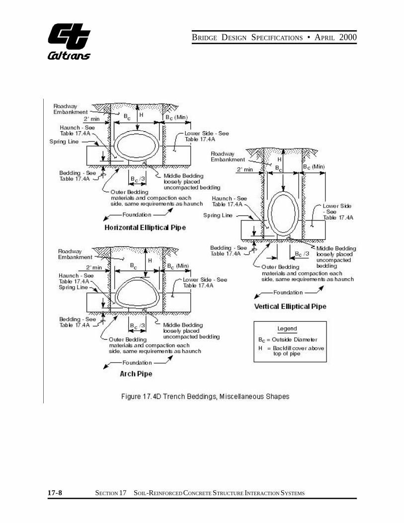
4. Only Type 2 and 3 installations are available for horizontal elliptical, vertical elliptical and arch pipe.
5. SUBTRENCHES 5.1 A subtrench is defined as a trench with its top below finished
grade by more than 0.1H or, for roadways, its top is at an elevation lower than 1' (0.3 m) below the bottom of the pavement base material.
5.2 For subtrenches with walls of natural soil, any portion of the lower side zone in the subtrench wall shall be at least as firm as an equivalent soil placed to the compaction requirements specified for the lower side zone and as firm as the majority of soil in the overfill zone, or shall be removed and replaced with soil compacted to the specified level. See Construction Manual.
TRENCH NOTES: 1. The bedding thickness shall be Bc/ 24" minimum but not less
than 3". If an unyielding material is encountered at the planned elevation of the bedding, it shall be removed to a depth of H/50 but in no case less than 6" nor more than 12". The resulting trench below the bottom of the bedding shall be backfilled with Structure Backfill and compacted.
2. The Lower Side shall be suitable material as determined by the engineer. See Construction Manual.
3. The trench top elevation shall be no lower than 0.1H below finished grade or, for roadways, its top shall be no lower than an elevation of 1' (0.3 m) below the bottom of the pavement base material.
4. Only Type 2 and 3 installations are available for horizontal elliptical, vertical elliptical and arch pipe.
5. Soil in the outer bedding, haunch and lower side zones except for installation Type 3 shall be compacted to at least the same compaction as the majority of soil in the over fill zone.
6. The trench width shall be wider than shown if required for adequate space to attain the specified compaction in the haunch and bedding zones.
7. For trench walls that are within 10 degrees of vertical, the compaction or firmness of the soil in the trench walls and lower side zone need not be considered.
8. For trench walls with greater than 10-degree slopes that consist of embankment, the lower side shall be compacted to at least the same compaction as specified for the soil in the backfill zone.
+ +
+ + + + + + + +
17-4 SECTION 17 SOIL-REINFORCED CONCRETE STRUCTURE INTERACTION SYSTEMS

BRIDGE DESIGN SPECIFICATIONS • APRIL 2000
+ +
+ +
17.4.4.2 Loads
17.4.4.2.1 Earth Loads and Pressure Distribution
The effects of soil-structure interaction shall be taken into account and shall be based on the design earth cover, sidefill compaction, and bedding characteristics of the pipe soil installations.
17.4.4.2.1.1 Standard Installations
For the Standard Installations given in 17.4.3.1, the earth load, WE, may be determined by multiplying the prism load (weight of the column of earth) over the pipes outside diameter by the soil-structure interaction factor, Fe, for the specified installation type.
WE=FewBcH (17-1)
Standard Installations for both embankments and trenches shall be designed for positive projection, embankment loading conditions where Fe = VAF given, in Figure 17.4A for each Type of Standard Installation.
For Standard Installations the earth pressure distribution shall be the Heger pressure distribution shown in Figure 17.4A for each type of Standard Installation.
The unit weight of soil used to calculate earth load shall be the estimated unit weight for the soils specified for the pipe-soil installation and shall not be less than 110 lbs/cu. ft. (120 lbs/cu. ft for pipe designed by the indirect method)
17.4.4.2.1.2 Non-Standard Installations
When nonstandard installations are used, the earth load on the structure shall be the prism load (PL). The unit weight of soil shall be 140 lbs/cu. ft. Pressure distribution
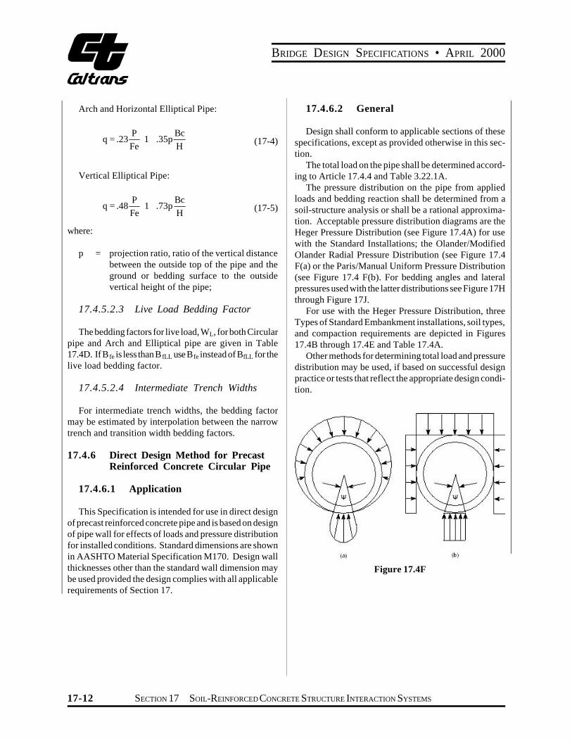
shall be determined by an appropriate soil-structure interaction analysis. See Figure 17.4F for suggested pressure distributions.
17.4.4.2.2 Pipe Fluid Weight
The weight of fluid, Wf in the pipe shall be considered in design based on a fluid weight of 62.4 lbs/ft3, unless otherwise specified. For Standard Installations, the fluid weight shall be supported by vertical earth pressure that is assumed to have the same distribution over the lower part of the pipe as given in figure 17.4A for earth load.
17.4.4.2.3 Live Loads
Live loads shall be the AASHTO HS – Series truck load. Live loads shall be distributed through the earth cover as specified in Article 6.5. For Standard Installations the live load on the pipe shall be assumed to have a uniform distribution across the top of the pipe and the same distribution across the bottom of the pipe as given in Figure 17.4A for earth load.
17.4.4.3 Minimum Fill
For unpaved areas and under flexible pavements the minimum fill over precast reinforced concrete pipes shall be two feet. For rigid pavements this distance shall be one foot.
17.4.4.4 Design Methods
The structural design requirements of installed precast reinforced concrete circular pipe for both standard and nonstandard installations may be determined by either the Indirect or Direct Method. Elliptical pipe in nonstandard installations may be designed by either the indirect or direct method. Elliptical pipe in standard installations, and arch pipe regardless of installation type shall be designed by the indirect method.
+ +
+
+ +
+ + + + + + + +
SECTION 17 SOIL-REINFORCED CONCRETE STRUCTURE INTERACTION SYSTEMS 17-5

BRIDGE DESIGN SPECIFICATIONS • APRIL 2000
Installation Type
1 1.35 0.45 0.62 0.73 1.35 0.19 0.08 0.18 1.40 0.40 0.18 0.08 0.05 0.80 0.80 2 1.40 0.40 0.85 0.55 1.40 0.15 0.08 0.17 1.45 0.40 0.19 0.10 0.05 0.82 0.70 3 1.40 0.37 1.05 0.35 1.40 0.10 0.10 0.17 1.45 0.36 0.20 0.12 0.05 0.85 0.60
VAF HAF A1 A2 A3 A4 A5 A6 a b c e f u v
Notes: 1. VAF and HAF are vertical and horizontal arching factors. These coefficients represent nondimensional total vertical and
horizontal loads on the pipe, respectively. The actual total vertical and horizontal loads are (VAF) X (PL) and (HAF) X (PL), respectively, where PL is the prism load.
2. Coefficients A1 through A6 represent the integration of nondimensional vertical and horizontal components of soil pressure under the indicated portions of the component pressure diagrams (i.e., the area under the component pressure diagrams). The pressures are assumed to vary either parabolically or linearly, as shown, with the nondimensional magnitudes at governing points represented by h 1, h2, uh1, vh1, a and b. Nondimensional horizontal and vertical dimensions of component pressure regions are defined by c, d, e, uc, vd and f coefficients.
3. d is calculated as (0.5 c-e) h1 is calculated as (1.5A1) / (c) (I + u) h2 is calculated as (1.5A2) / [(d) (1 + v) + (2e)].
Figure 17.4A Heger Pressure Distribution and Arching Factors
17-6 SECTION 17 SOIL-REINFORCED CONCRETE STRUCTURE INTERACTION SYSTEMS

BRIDGE DESIGN SPECIFICATIONS • APRIL 2000
Figure 17.4B
Figure 17.4C
SECTION 17 SOIL-REINFORCED CONCRETE STRUCTURE INTERACTION SYSTEMS 17-7
BRIDGE DESIGN SPECIFICATIONS • APRIL 2000
17-8 SECTION 17 SOIL-REINFORCED CONCRETE STRUCTURE INTERACTION SYSTEMS

BRIDGE DESIGN SPECIFICATIONS • APRIL 2000
SECTION 17 SOIL-REINFORCED CONCRETE STRUCTURE INTERACTION SYSTEMS 17-9

BRIDGE DESIGN SPECIFICATIONS • APRIL 2000
17.4.5 Indirect Design Method Based on Table 17.4B Design Values of Parameters in Pipe Strength and Load-Carrying Bedding Factor Equation Capacity
Pipe Shape Values of CA
Type of Bedding
Values of CN
Projection Ratio
Values of x
Horizontal Elliptical And Arch
1.337 Type 2
Type 3
0.630
0.763
0.9 0.7 0.5 0.3
0.421 0.369 0.268 0.148
Vertical Elliptical 1.021
Type 2
Type 3
0.516
0.615
0.9 0.7 0.5 0.3
0.718 0.639 0.457 0.238
17.4.5.1 Loads
The design load-carrying capacity of a reinforced concrete pipe must equal the design load determined for the pipe as installed, or
Ø Ø12 WE WF WL
B B +ø ø
D +μ
= μ
(17-2)ϧ
ϧSl fe fLL
where:
D = D-load of the pipe (three-edge-bearing test load expressed in pounds per linear foot per Table 17.4C Bedding Factors for Circular Pipefoot of diameter) to produce a 0.01-inch crack. For Type 1 installations, D-load as
Standard Installationscalculated above shall be modified by multiplying by an installation factor of 1.10;
Si = internal diameter or horizontal span of the pipe in inches;
Bf = bedding factor, See Article 17.4.5.2;
Pipe Diameter, in. Type 1 Type 2 Type 3 12 4.4 3.2 2.5 24 4.2 3.0 2.4 36 4.0 2.9 2.3 72 3.8 2.8 2.2
144 3.6 2.8 2.2 Note: 1. For pipe diameters other than listed, embankment
Bfe = earth load bedding factor; condition bedding factors, Bfc can be obtained by interpolation. Bedding factors are based on soils being placed with the minimum compaction specified in Table 17.4A for
BfLL = live load bedding factor; 2.
WT = WE + WL;
WT = total load on the pipe as determined according to Article 17.4.4;
WE = earth load on the pipe as determined according to Article 17.4.4;
WF = fluid load in the pipe as determined according to Article 17.4.4.2.2;
WL = live load on the pipe as determined according to Article 17.4.4.
each Standard Installation.
17-10 SECTION 17 SOIL-REINFORCED CONCRETE STRUCTURE INTERACTION SYSTEMS

BRIDGE DESIGN SPECIFICATIONS • APRIL 2000
+
Table 17.4D Bedding Factors
Pipe Diam
BfLL for HS20 Live Loadings
eter, in. Fill Height, Ft 12 24 36 48 60 72 84 96 108 120 144
0.5 2.2 1.7 1.4 1.3 1.3 1.1 1.1 1.1 1.1 1.1 1.1 1.0 2.2 2.2 1.7 1.5 1.4 1.3 1.3 1.3 1.1 1.1 1.1 1.5 2.2 2.2 2.1 1.8 1.5 1.4 1.4 1.3 1.3 1.3 1.1 2.0 2.2 2.2 2.2 2.0 1.8 1.5 1.5 1.4 1.4 1.3 1.3 2.5 2.2 2.2 2.2 2.2 2.0 1.8 1.7 1.5 1.4 1.4 1.3 3.0 2.2 2.2 2.2 2.2 2.2 2.2 1.8 1.7 1.5 1.5 1.4 3.5 2.2 2.2 2.2 2.2 2.2 2.2 1.9 1.8 1.7 1.5 1.4 4.0 2.2 2.2 2.2 2.2 2.2 2.2 2.1 1.9 1.8 1.7 1.5 4.5 2.2 2.2 2.2 2.2 2.2 2.2 2.2 2.0 1.9 1.8 1.7 5.0 2.2 2.2 2.2 2.2 2.2 2.2 2.2 2.2 2.0 1.9 1.8 5.5 2.2 2.2 2.2 2.2 2.2 2.2 2.2 2.2 2.2 2.0 1.9 6.0 2.2 2.2 2.2 2.2 2.2 2.2 2.2 2.2 2.2 2.1 2.0
17.4.5.1.1 Ultimate D-load
The required D-load at which the pipe develops its ultimate strength in a three-edge-bearing test is the design D-load (at 0.01-inch crack) multiplied by a strength factor that is specified in AASHTO materials specifications M 170 or M 242 (ASTM C 76 or C 655) for Circular pipe, M 206 (ASTM C 506) for Arch Pipe and M 207 (ASTM C 507) for Elliptical Pipe.
17.4.5.2 Bedding Factor
The bedding factor, Bf, is the ratio of the supporting strength of buried pipe to the strength of the pipe determined in the three-edge-bearing test. The supporting strength of buried pipe depends on the type of Standard Installation. See figures 17.4B and 17.4C for circular pipe and figures 17.4D and 17.4E for other arch and elliptical shapes. Table 17.4A applies to circular, arch and elliptical shapes.
17.4.5.2.1 Earth Load Bedding Factor for Circular Pipe
Earth load bedding factors, Bfe, for circular pipe are presented in Table 17.4C.
6.5 2.2 2.2 2.2 2.2 2.
Note: For pipe diameters other than listed, BfLL values can be
17.4.5.2.2 Earth Load Bedding Factor for Arch and Elliptical Pipe
The bedding factor for installations of arch and elliptical pipe, Figures 17.4D and 17.4E, is:
xqC C
B N
A fe -
= (17-3)
Values for CA and CN are listed in Table 17.4B.
CA = a constant corresponding to the shape of the pipe;
CN = a parameter which is a function of the distribution of the vertical load and vertical reaction;
x = a parameter which is a function of the area of the vertical projection of the pipe over which lateral pressure is effective;
q = the ratio of the total lateral pressure to the total vertical fill load. Design values for CA, CN, and x are found in Table 17.4B. The value of q is determined by the following equations:
2 2.2 2.2 2.2 2.2 2.2 2.2
obtained by interpolation.
SECTION 17 SOIL-REINFORCED CONCRETE STRUCTURE INTERACTION SYSTEMS 17-11
BRIDGE DESIGN SPECIFICATIONS • APRIL 2000
Arch and Horizontal Elliptical Pipe: 17.4.6.2 General
q =.23 P
Fe 1 Ł( +.35p
Bc H
ł)
(17-4) Design shall conform to applicable sections of these
specifications, except as provided otherwise in this section.
The total load on the pipe shall be determined accord-Vertical Elliptical Pipe: ing to Article 17.4.4 and Table 3.22.1A.
The pressure distribution on the pipe from applied
q =.48 P
Fe 1 Ł( +.73p
Bc H
ł)
(17-5) loads and bedding reaction shall be determined from a soil-structure analysis or shall be a rational approximation. Acceptable pressure distribution diagrams are the
where:
p = projection ratio, ratio of the vertical distance between the outside top of the pipe and the ground or bedding surface to the outside vertical height of the pipe;
17.4.5.2.3 Live Load Bedding Factor
The bedding factors for live load, WL, for both Circular pipe and Arch and Elliptical pipe are given in Table 17.4D. If Bfe is less than BfLL use Bfe instead of BfLL for the live load bedding factor.
17.4.5.2.4 Intermediate Trench Widths
For intermediate trench widths, the bedding factor may be estimated by interpolation between the narrow trench and transition width bedding factors.
17.4.6 Direct Design Method for Precast Reinforced Concrete Circular Pipe
17.4.6.1 Application
This Specification is intended for use in direct design of precast reinforced concrete pipe and is based on design of pipe wall for effects of loads and pressure distribution for installed conditions. Standard dimensions are shown in AASHTO Material Specification M170. Design wall thicknesses other than the standard wall dimension may be used provided the design complies with all applicable requirements of Section 17.
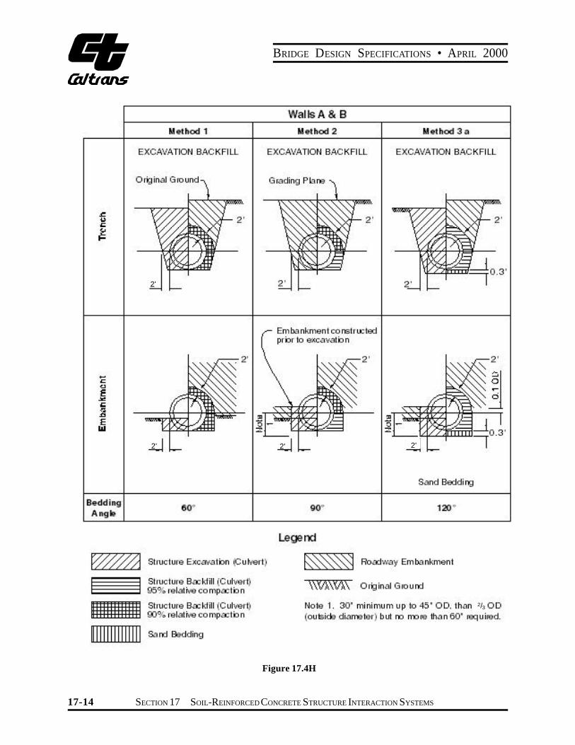
Heger Pressure Distribution (see Figure 17.4A) for use with the Standard Installations; the Olander/Modified Olander Radial Pressure Distribution (see Figure 17.4 F(a) or the Paris/Manual Uniform Pressure Distribution (see Figure 17.4 F(b). For bedding angles and lateral pressures used with the latter distributions see Figure 17H through Figure 17J.
For use with the Heger Pressure Distribution, three Types of Standard Embankment installations, soil types, and compaction requirements are depicted in Figures 17.4B through 17.4E and Table 17.4A.
Other methods for determining total load and pressure distribution may be used, if based on successful design practice or tests that reflect the appropriate design condition.
Figure 17.4F
17-12 SECTION 17 SOIL-REINFORCED CONCRETE STRUCTURE INTERACTION SYSTEMS

BRIDGE DESIGN SPECIFICATIONS • APRIL 2000
Figure 17.4G General Relationship of Vertical Earth Load and Lateral Pressure
17.4.6.3 Strength-Reduction Factors
Strength-reduction factors for load factor design of plant made reinforced concrete pipe may be taken as 1.0 for flexure (f ƒ) and 0.9 for shear (f v) and radial tension (f r). For type 1 installations, the strength-reduction factor shall be 0.9 for flexure and 0.82 for shear and radial tension.
17.4.6.4 Process and Material Factors
Process and material factors, Frp for radial tension and Fvp for shear strength for load factor design of plant made reinforced concrete pipe are conservatively taken as 1.0. Higher values may be used if substantiated by appropriate test data approved by the Engineer.
17.4.6.5 Orientation Angle
When quadrant mats, stirrups and/or elliptical cages are used, the pipe installation requires a specific orientaion. Designs shall be based on the possibility of a rotation misorientation during installation by an Orientation Angle of 10 degrees in either direction.
17.4.6.6 Reinforcement
17.4.6.6.1 Reinforcement for Flexural Strength
( 2 ) 1AS = gf d - NU - g[g(ffd) - NU (2f d - h)- 2MU ]f fŁ ł fy
(17-6)
where g = 0.85b f ¢c b = 12 in.
17.4.6.6.2 Minimum Reinforcement
For inside face of pipe:
A = b (Si + h)2 /(fy ) (17-7)si 12
where b = 12 in.
For outside face of pipe:
( b ) 2Aso = 0.60 (Si + h) /(fy ) (17-8)Ł12 ł
where b = 12 in.
For elliptical reinforcement in circular pipe and for pipe 33-inch diameter and smaller with a single cage of reinforcement in the middle third of the pipe wall, reinforcement shall not be less than As, where:
( b ) 2As = 2 (Si + h) /(fy ) (17-9)Ł12 ł
where b = 12 in.
where: h = wall thickness in inches;
Si = internal diameter or horizontal span of pipe in inches.
In no case shall the minimum reinforcement be less than 0.07 square inches per linear foot.
SECTION 17 SOIL-REINFORCED CONCRETE STRUCTURE INTERACTION SYSTEMS 17-13
BRIDGE DESIGN SPECIFICATIONS • APRIL 2000
Figure 17.4H
2'
2'2' 2'
2/3
17-14 SECTION 17 SOIL-REINFORCED CONCRETE STRUCTURE INTERACTION SYSTEMS

BRIDGE DESIGN SPECIFICATIONS • APRIL 2000
2/3
Figure 17.4I
SECTION 17 SOIL-REINFORCED CONCRETE STRUCTURE INTERACTION SYSTEMS 17-15

BRIDGE DESIGN SPECIFICATIONS • APRIL 2000
Figure 17.4J
17.4.6.6.3 Maximum Flexural Frp = 1.0 unless a higher value substantiated byReinforcement Without Stirrups test data is approved by the Engineer;
2(144 -S )i17.4.6.6.3.1 Limited by Radial = + 0.80Frt 26,000Tension
For 72 in. < Si = 144 in. ( b ) ( ( f ) )r
Inside As max = 16rsFrp fc¢ Frt /(fy ) Frt = 0.8 for Si > 144 in.Ł 12 ł Ł ff łŁ ł
rs = radius of the inside reinforcement in inches.(17-10)
17.4.6.6.3.2 Limited by Concrete Compression
As max = maximum flexural reinforcement area with
out stirrups in.2 where b = 12 in.ft
( Ø ø )5.5·104g¢f dfAs max = Œ œ - 0.75NU /(fy ) (17-11)Frt = 1 + 0.00833 (72 – Si) 87,000 + fŒ y œŁ º ß łFor 12 in £ Si £ 72 in.
17-16 SECTION 17 SOIL-REINFORCED CONCRETE STRUCTURE INTERACTION SYSTEMS

BRIDGE DESIGN SPECIFICATIONS • APRIL 2000
+ + +
where:
Ø (f g¢ = bf ¢ 0.85 - 0.05c Œ
º
g¢ = 0.85 bf ¢ and g¢c min
c¢ - 4,000)ø 1,000 œ
ß
= 0.65 bfc¢
17.4.6.6.4 Crack Width Control (Service Load Design)
Ø ( h ) øM + N d Œ s s œBl Ł 2 ł 2 fc¢ œcr 30,000ff dAs Œ ij lF = Œ - C bh
œ Œ œº ß
(17-12)
Cover for crack control analysis is assumed to be 1 in. over the tension reinforcement, even if it is greater or less than 1 in. The crack control factor Fcr in equation 17-12 indicates the probability that a crack of a specified maximum width will occur.
When Fcr = 1.0, the reinforcement area, As, will produce an average crack maximum width of 0.01 inch. For Fcr
values less than 1.0, the probability of a 0.01 inch crack is reduced. For Fcr values greater than 1.0, the probability of a crack greater than 0.01 inch is increased.
where:
Fcr = crack control factor Ms = bending moment, service load; Ns = thrust (positive when compressive), service load.
If the service load thrust, Ns, is tensile rather than compressive (this may occur in pipes subject to intermittent hydrostatic pressure), use the quantity (1.1Ms – 0.6Nsd) (with tensile Ns taken negative) in place of the quantity ([Ms + Ns(d – h/2)]/ji) in Equation (17-12).
j @ 0.74 + 0.1e/d; j = 0.9;max
1i =
jd1-
e Ms h
e = + d - ,in.Ns 2
if e/d <1.15 crack control will not govern.
tb = clear cover over reinforcement in inches h = wall thickness of pipe in inches;
l 3 tbs�/2nB =
where:
s� = spacing of circumferential reinforcement, in. n = 1, when tension reinforcement is a single layer. n = 2, when tension reinforcement is made of
multiple layers.
C1 = Crack Control Coefficient
Type of Reinforcement: C1
1. Smooth wire or plain bars 1.0
2. Welded smooth wire fabric, 8in. (200mm) maximum spacing of longitudinals 1.5
3. Welded deformed wire fabric, deformed wire, deformed bars or any reinforcement with stirrups
anchored thereto. 1.9 Notes: Higher values for C1 may be used if substantiated by
test data and approved by the Engineer.
17.4.6.6.5 Shear Strength
The area of reinforcement, As, determined in Article 17.4.6.6.1 or 17.4.6.6.4 must be checked for shear strength adequacy, so that the basic shear strength, Vb, is greater than the factored shear force, Vuc, at the critical section located where Mnu/Vud = 3.0.
Ø FdFN øV = bf dF fc¢ (1.1+ 63r )º ß (17-13)b v vp Œ Fc œ
where
Vb = shear strength of section where Mnu/Vud = 3.0;
Fvp = 1.0 unless a higher value substantiated by test data is approved by the Engineer; As r = bd
rmax = 0.02;
f ¢ = 7,000 psi;c max
SECTION 17 SOIL-REINFORCED CONCRETE STRUCTURE INTERACTION SYSTEMS 17-17

BRIDGE DESIGN SPECIFICATIONS • APRIL 2000
1.6Fd = 0.8 +
d
max Fd = 1.3 for pipe with two cages, or a single elliptical cage
max Fd = 1.4 for pipe through 36-inch diameter with a single circular cage
dFc = 1–
2r
(+) tension on the inside of the pipe (-) tension on the outside of the pipe
For compressive thrust (+ Nu):
N1+FN =
U 2,000bh
where b = 12 in.
For tensile thrust (-Nu):
NFN = 1+ U
500bh
where b = 12 in.
Mnu = Mu - Nu
If Vb is less than Vuc, radial stirrups must be provided. See Article 17.4.6.6.6.
17.4.6.6.6 Radial Stirrups
17.4.6.6.6.1 Radial Tension Stirrups
1.1s (M - 0.45N f d)v u u r=Avr (17-14)f r f dv s r
where:
Avr = required area of stirrup reinforcement for radial tension;
sv = circumferential spacing of stirrups (sv max = 0.75fvd);
fv = maximum allowable strength of stirrup material (fmax = fy, or anchorage strength whichever is less).
17.4.6.6.6.2 Shear Stirrups
vsA = [ cu vvs
v V F df
1.1s f c ]V- (17-15)
where:
Avs = required area of stirrups for shear reinforcement;
Vu = factored shear force at section; 4Vb
Vc = V d M
u
nu 1+
Vc max = 2f vbd cf ¢
Sv max = 0.75f vd
fv max = fy or anchorage strength, whichever is less
A conservative approximation of the total required stirrup area is:
Av = Avs + Avr
17.4.6.6.6.3 Stirrup Reinforcement Anchorage
17.4.6.6.6.3.1 Radial Tension Stirrup Anchorage
When stirrups are used to resist radial tension, they shall be anchored around each circumferential of the inside cage to develop the design strength of the stirrup, and they shall also be anchored around the outside cage, or embedded sufficiently in the compression side to develop the design strength of the stirrup.
17.4.6.6.6.3.2 Shear Stirrup Anchorage
When stirrups are not required for radial tension but required for shear, their longitudinal spacing shall be such that they are anchored around each or every other tension circumferential. Such spacings shall not exceed 6 inches (150 mm).
+ + +
17-18 SECTION 17 SOIL-REINFORCED CONCRETE STRUCTURE INTERACTION SYSTEMS
�
BRIDGE DESIGN SPECIFICATIONS • APRIL 2000
+
+
+
17.4.6.6.6.3.3 Stirrup Embeddment
Stirrups intended to resist forces in the invert and crown regions shall be anchored sufficiently in the opposite side of the pipe wall to develop the design strength of the stirrup.
17.4.6.6.6.3.4 Other Provisions
Section 8.27, Development of Shear Reinforcement, does not apply to pipe designed according to provisions of Section 17.4.5.
17.4.7 Development of Quadrant Mat Reinforcement
17.4.7.1 When the quadrant mat reinforcement is used, the area of the continuous main cages shall be no less than 25% of the area required at the point of maximum moment.
17.4.7.2 In lieu of 17.4.7.1, a more detailed analysis may be made.
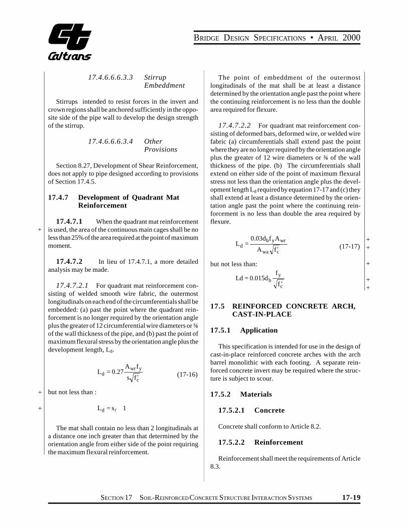
17.4.7.2.1 For quadrant mat reinforcement consisting of welded smooth wire fabric, the outermost longitudinals on each end of the circumferentials shall be embedded: (a) past the point where the quadrant reinforcement is no longer required by the orientation angle plus the greater of 12 circumferential wire diameters or ¾ of the wall thickness of the pipe, and (b) past the point of maximum flexural stress by the orientation angle plus the development length, Ld.
AwrfyL = 0.27d (17-16)s fc¢
but not less than :
Ld = s +1
The mat shall contain no less than 2 longitudinals at a distance one inch greater than that determined by the orientation angle from either side of the point requiring the maximum flexural reinforcement.
The point of embeddment of the outermost longitudinals of the mat shall be at least a distance determined by the orientation angle past the point where the continuing reinforcement is no less than the double area required for flexure.
17.4.7.2.2 For quadrant mat reinforcement consisting of deformed bars, deformed wire, or welded wire fabric (a) circumferentials shall extend past the point where they are no longer required by the orientation angle plus the greater of 12 wire diameters or ¾ of the wall thickness of the pipe. (b) The circumferentials shall extend on either side of the point of maximum flexural stress not less than the orientation angle plus the development length Ld required by equation 17-17 and (c) they shall extend at least a distance determined by the orientation angle past the point where the continuing reinforcement is no less than double the area required by flexure.
0.03d f Ab y wrL =d (17-17)Awa fc¢
but not less than: fyLd = 0.015db fc¢
17.5 REINFORCED CONCRETE ARCH, CAST-IN-PLACE
17.5.1 Application
This specification is intended for use in the design of cast-in-place reinforced concrete arches with the arch barrel monolithic with each footing. A separate reinforced concrete invert may be required where the structure is subject to scour.
17.5.2 Materials
17.5.2.1 Concrete
Concrete shall conform to Article 8.2.
17.5.2.2 Reinforcement
Reinforcement shall meet the requirements of Article 8.3.
+ +
+
+ +
SECTION 17 SOIL-REINFORCED CONCRETE STRUCTURE INTERACTION SYSTEMS 17-19

BRIDGE DESIGN SPECIFICATIONS • APRIL 2000
17.5.3 Design
17.5.3.1 General Requirements
Design shall conform to these specifications except as provided otherwise in this Section. For design loads and
+ loading conditions, see Article 3.2 and Section 6. For reinforced concrete design requirements see Section 8.
17.5.3.2 Minimum Cover
The minimum fill over reinforced concrete arches shall + be 2 feet or Span /8.
17.5.3.3 Strength-Reduction Factors
Strength reduction factors for load factor design of cast-in-place arches may be taken as 0.90 for flexure and 0.85 for shear.
17.5.3.4 Splices of Reinforcement
Reinforcement shall be in conformity with Article + 8.32. If lap splicing is used, laps shall be staggered with
a minimum of one foot measured along the circumference of the arch. Ties shall be provided connecting the intrados and extrados reinforcement. Ties shall be at 12-inch maximum spacing, in both longitudinal and circumferential directions, except as modified by shear.
17.5.3.5 Footing Design
Design shall include consideration of differential horizontal and vertical movements and footing rotations. Footing design shall conform to Article 4.4.
17.6 REINFORCED CONCRETE BOX, CAST-IN-PLACE
17.6.1 Application
The specification is intended for use in the design of cast-in-place reinforced concrete box culverts.
17.6.2 Materials
17.6.2.1 Concrete
Concrete shall conform to Article 8.2 except that evaluation of f ¢ may be based on test beams.c
17.6.2.2 Reinforcement
Reinforcement shall meet the requirements of Article 8.3 except that for welded wire fabric a yield strength of 65,000 psi may be used. For wire fabric, the spacing of longitudinal wires shall be a maximum of 8 inches.
17.6.3 Concrete Cover for Reinforcement
The minimum concrete cover for reinforcement shall conform to Article 8.22. The top slab shall be considered a bridge slab for concrete cover considerations.
17.6.4 Design
17.6.4.1 General Requirements
Designs shall conform to applicable sections of these specifications except as provided otherwise in this section. For design loads and loading conditions see Section 3. For distribution of concentrated loads through earth for culverts with 2 feet or less of cover see Article 3.24.3, Case B, and for requirements for bottom distribution reinforcement in top slabs of such culverts see Article 3.24.10. For distribution of wheel loads to culverts with more than 2 feet of cover see Article 6.5. For reinforced concrete design requirements see Section 8.
17.6.4.2 Deleted
17.6.4.3 Distribution of Concentrated Load Effects to Bottom Slab
Concentrated wheel loads may be distributed over the full width of the bottom slab transversely and over 7' longitudinally.
17.6.4.4 Distribution of Concentrated Loads in Skewed Culverts
Wheel loads on skewed culverts shall be distributed using the same provisions as given for culverts with main reinforcement parallel to traffic.
+
+ +
+ + +
17-20 SECTION 17 SOIL-REINFORCED CONCRETE STRUCTURE INTERACTION SYSTEMS

BRIDGE DESIGN SPECIFICATIONS • APRIL 2000
17.6.4.5 Span Length
For span length see Article 8.8, except when monolithic haunches included at 45 degrees are considered in the design, negative moment reinforcement in walls and slabs may be proportioned based on the bending moment
+ where the depth of the haunch equals 1.5 times the + thickness of the member.
17.6.4.6 Strength Reduction Factors
Strength reduction factors for load factor design may be taken as 0.9 for combined flexure and thrust and as 0.85 shear.
17.6.4.7 Crack Control
The service load stress should be computed considering the effects of both bending moment and thrust using:
( h )Ms + Ns d -Ł 2 ł= (17-18)fss (A jid)s
where:
fss = stress in reinforcement under service load conditions, psi
e = Ms/Ns+d-h/2 e/d min. = 1.15 i = 1/(1-(jd/e)) j = 0.74 + 0.1 (e/d) <= 0.9
The maximum allowable service load stress in the reinforcing steel for crack control shall be:
155fs = £ 0.6fy ksi
3 (17-19)ß dcA
Ø dc øb = 1+Œ œº 0.7d ß
b = approximate ratio of distance from the neutral axis to the location of the crack width at the concrete surface divided by the distance from the neutral axis to the centroid of tensile reinforcing.
dc = distance measured from the extreme tension fiber to the center of the closest bar or wire in inches. For
calculation purposes, the thickness of clear concrete cover used to compute dc shall not be taken greater than 2 inches.
17.6.4.8 Minimum Reinforcement
Minimum reinforcement shall be provided in accordance with Article 8.17.1 at all cross sections subject to flexural tension, including the inside face of walls. Shrinkage and temperature reinforcement shall be provided near the inside surfaces of walls and slabs in accordance with Article 8.20.
17.7 REINFORCED CONCRETE BOX, PRECAST
17.7.1 Application
This specification is intended for use in design of precast reinforced concrete box sections. Boxes may be manufactured using conventional structural concrete and forms (formed) or with dry concrete and vibrating form pipe making methods (machine-made). Standard dimensions are shown in AASHTO Materials Specification M 259, and M 273.
17.7.2 Materials
17.7.2.1 Concrete
Concrete shall conform to Article 8.2 except that evaluation of f ¢ may be based on cores.c
17.7.2.2 Reinforcement
Reinforcement shall meet the requirements of Article 8.3 except that for welded wire fabric a yield strength of 65,000 psi may be used. For wire fabric, the spacing of longitudinal wires shall be a maximum of 8 inches.
17.7.3 Concrete Cover for Reinforcement
The minimum design concrete cover for reinforcement in boxes reinforced with wire fabric shall be 1 inch. +
SECTION 17 SOIL-REINFORCED CONCRETE STRUCTURE INTERACTION SYSTEMS 17-21
BRIDGE DESIGN SPECIFICATIONS • APRIL 2000
+ + + + + +
+
+ +
17.7.4 Design
17.7.4.1 General Requirements
Design shall conform to applicable sections of these specifications except as provided otherwise in this Section. For design loads and loading conditions see Section 3. For distribution of wheel loads to culvert slabs with 2 feet or less of cover see Article 3.24.3, Case B, and for requirements for bottom reinforcement in top slabs of such culverts see Article 3.24.10. For distribution of wheel loads to culvert slabs with more than 2 feet of cover, see Article 6.4.
For reinforced concrete design requirements see Section 8. For span length see Article 8.8, except as noted in Article 17.7.4.5.
17.7.4.2 Deleted
17.7.4.3 Distribution of Concentrated Load Effects in Sides and Bottoms
The width of the top slab strip used for distribution of concentrated wheel loads shall also be used for determination of bending moments, shears and thrusts in the sides and bottom.
17.7.4.4 Distribution of Concentrated Loads in Skewed Culverts
Wheel loads on skewed culverts shall be distributed using the same provisions as given for culverts with main reinforcement parallel to traffic.
17.7.4.5 Span Length
When monolithic haunches inclined at 45 degrees are taken into account, negative reinforcement in walls and slabs may be proportioned based on the bending moment where the depth of the haunch equals 1.5 times the thickness of the member.
17.7.4.6 Strength Reduction Factors
Strength reduction factors for load factor design of machine-made boxes may be taken as 1.0 for moment and 0.9 for shear.
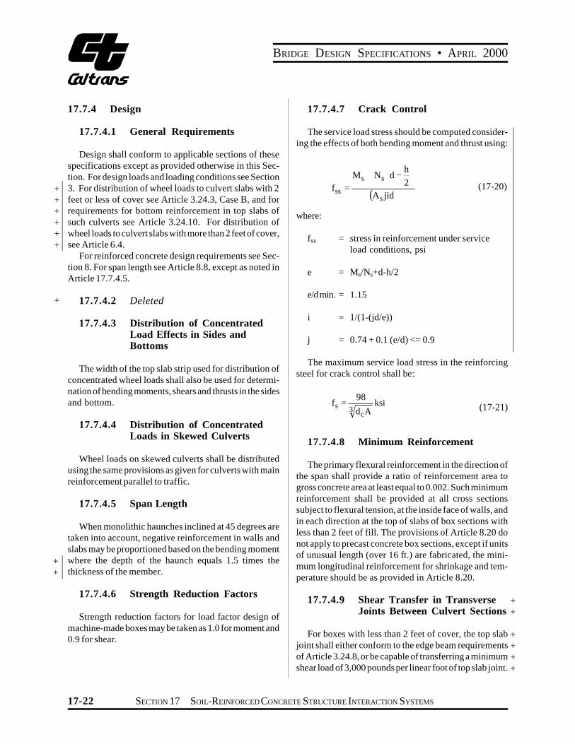
17.7.4.7 Crack Control
The service load stress should be computed considering the effects of both bending moment and thrust using:
( h )Ms + Ns d -Ł 2 łf = (17-20)ss (A jid)s
where:
fss = stress in reinforcement under service load conditions, psi
e = Ms/Ns+d-h/2
e/d min. = 1.15
i = 1/(1-(jd/e))
j = 0.74 + 0.1 (e/d) <= 0.9
The maximum service load stress in the reinforcing steel for crack control shall be:
98fs = ksi
3 (17-21)dcA
17.7.4.8 Minimum Reinforcement
The primary flexural reinforcement in the direction of the span shall provide a ratio of reinforcement area to gross concrete area at least equal to 0.002. Such minimum reinforcement shall be provided at all cross sections subject to flexural tension, at the inside face of walls, and in each direction at the top of slabs of box sections with less than 2 feet of fill. The provisions of Article 8.20 do not apply to precast concrete box sections, except if units of unusual length (over 16 ft.) are fabricated, the minimum longitudinal reinforcement for shrinkage and temperature should be as provided in Article 8.20.
17.7.4.9 Shear Transfer in Transverse + Joints Between Culvert Sections +
For boxes with less than 2 feet of cover, the top slab + joint shall either conform to the edge beam requirements + of Article 3.24.8, or be capable of transferring a minimum + shear load of 3,000 pounds per linear foot of top slab joint. +
17-22 SECTION 17 SOIL-REINFORCED CONCRETE STRUCTURE INTERACTION SYSTEMS

BRIDGE DESIGN SPECIFICATIONS • APRIL 2000
+ + +
+
If individual shear connectors are used, they shall be spaced at no more than 2.5 feet on center with a minimum of of 2 connectors per joint.
17.8 PRECAST REINFORCED CONCRETE THREE-SIDED STRUCTURES
17.8.1 Application
This specification is intended for use in design of precast reinforced concrete three-sided structures supported on a concrete footing foundation. Units may be manufactured using conventional structural concrete and forms (formed) or machine made using low slump concrete and vibrating forms.
17.8.2 Materials
17.8.2.1 Concrete
Concrete shall conform to Article 8.2 except that evaluation of fc¢ may also be based on cores.
17.8.2.2 Reinforcement
Reinforcement shall meet the requirements of Article 8.3 except that for welded wire fabric a yield strength of 65,000 psi may be used. For wire fabric, the spacing of longitudinal wires shall be a maximum of 8 inches. Circumferential welded wire fabric spacing shall not exceed a 4-inch maximum and a 2-inch minimum. Prestressing if used, shall be in accordance with Section 9.
17.8.3 Concrete Cover for Reinforcement
The minimum concrete cover for reinforcement in precast three-sided structures reinforced with welded wire fabric shall be 1 inch.
17.8.4 Geometric Properties
The shape of the precast three-sided structures may vary in span, rise, wall thickness, haunch dimensions and curvature. Specific geometric properties shall be specified by the manufacturer. Wall thicknesses, however, shall be a minimum of 8 inches for spans under 24 feet and 10 inches for 24-foot spans and larger.
17.8.5 Design
17.8.5.1 General Requirements
Designs shall conform to applicable Sections of these specifications except as provided otherwise in this Section. For design loads and loading conditions see Section 3. For distribution of wheel loads to culvert surfaces under 2 feet and less of cover see Article 3.24.3, Case B. For requirements for bottom reinforcement in top slabs of such culverts see Article 3.24.10. For distribution of wheel loads to culvert surfaces with more than 2 feet of cover, see Article 6.5.
For reinforced concrete design requirements see Section 8 and for prestress concrete design requirements see Section 9. For span length see Article 8.8, except as noted in Article 17.8.5.5. Design analysis shall be based on a pinned (hinged) connection at the footing and take into account footing movement, see Article 17.8.5.10.
17.8.5.2 Distribution of Concentrated Load Effects in Side
The width of the top slab strip used for distribution of concentrated wheel loads shall also be used for determination of bending moments, shears and thrusts in the sides.
17.8.5.3 Distribution of Concentrated Loads in Skewed Culverts
Wheel loads on skewed culverts shall be distributed using the same provisions as given for culverts with main reinforcement parallel to traffic. For culvert elements with skews greater than 15°, the effect of the skew shall be considered in analysis.
17.8.5.4 Shear Transfer in Transverse Joints Between Culvert Section
Each precast three-sided structure is analyzed independently with no shear or stress transfer assumed between sections. As no shear transfer is assumed between sections, distribution width for a wheel load must be limited to the unit width. For structures with 2 feet and + less of cover, the top slab shall conform to the edge beam + requirements of Article 3.24.8 unless it is designed by a + finite element method in which case the moment applied + to the one foot edge section shall be 60% greater than that +
SECTION 17 SOIL-REINFORCED CONCRETE STRUCTURE INTERACTION SYSTEMS 17-23
BRIDGE DESIGN SPECIFICATIONS • APRIL 2000
+ calculated. Flat top structures with shallow cover may experience differential deflection of adjacent units which can cause pavement cracking if a shear key is not utilized.
17.8.5.5 Span Length
When monolothic haunches inclined at 45 degrees are taken into account, negative reinforcement in walls and slabs may be proportioned based on the bending moment where the depth of the haunch equals 1.5 times the thickness of the member.
17.8.5.6 Strength Reduction Factor
These structures shall be designed by load factor design and the maximum strength reduction factors shall be 0.95 for combined flexure and thrust and 0.9 for shear. See Section 8 and Section 9 for factors used for cast-inplace and prestressed components, respectively.
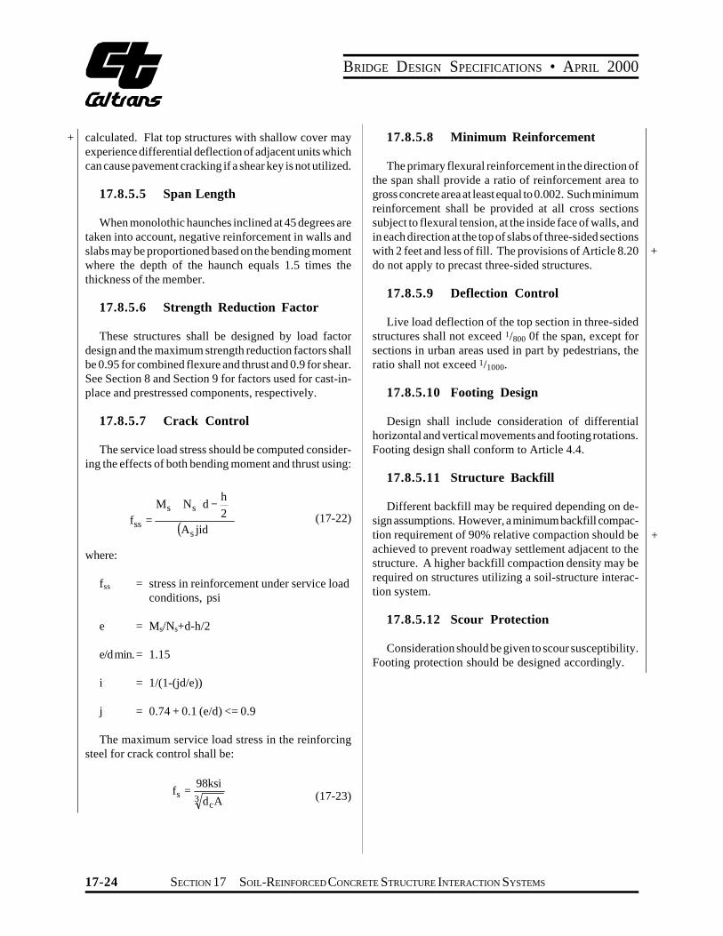
17.8.5.7 Crack Control
The service load stress should be computed considering the effects of both bending moment and thrust using:
( h )Ms + Ns d -Ł 2 ł= (17-22)fss (A jid)s
where:
fss = stress in reinforcement under service load conditions, psi
e = Ms/Ns+d-h/2
e/d min.= 1.15
i = 1/(1-(jd/e))
j = 0.74 + 0.1 (e/d) <= 0.9
The maximum service load stress in the reinforcing steel for crack control shall be:
98ksi =fs 3 (17-23)dcA
17.8.5.8 Minimum Reinforcement
The primary flexural reinforcement in the direction of the span shall provide a ratio of reinforcement area to gross concrete area at least equal to 0.002. Such minimum reinforcement shall be provided at all cross sections subject to flexural tension, at the inside face of walls, and in each direction at the top of slabs of three-sided sections with 2 feet and less of fill. The provisions of Article 8.20 do not apply to precast three-sided structures.
+
17.8.5.9 Deflection Control
Live load deflection of the top section in three-sided structures shall not exceed 1/800 0f the span, except for sections in urban areas used in part by pedestrians, the ratio shall not exceed 1/1000.
17.8.5.10 Footing Design
Design shall include consideration of differential horizontal and vertical movements and footing rotations. Footing design shall conform to Article 4.4.
17.8.5.11 Structure Backfill
Different backfill may be required depending on design assumptions. However, a minimum backfill compaction requirement of 90% relative compaction should be achieved to prevent roadway settlement adjacent to the structure. A higher backfill compaction density may be required on structures utilizing a soil-structure interaction system.
+
17.8.5.12 Scour Protection
Consideration should be given to scour susceptibility. Footing protection should be designed accordingly.
17-24 SECTION 17 SOIL-REINFORCED CONCRETE STRUCTURE INTERACTION SYSTEMS