section 14 reduced-gravity environment of ground …€¦ · reduced-gravity environment of...
TRANSCRIPT
March 2-4, 2004 MEIT-2004 / Section 14 / Page 1
Microgravity Ground-based Facilities
Section 14
Reduced-gravity Environment of Ground-based Facilities and Non-orbital Flight Platforms
Richard DeLombardAcceleration Measurement Discipline Scientist
NASA Glenn Research Center

March 2-4, 2004 MEIT-2004 / Section 14 / Page 2
Microgravity Ground-based Facilities
Acronym & Nomenclature List
a accelerationDARTFire Diffusion And Radiative
Transport-Controlled Fire (experiment)
F forcege Earth’s gravitational
acceleration (location dependent)
GRC NASA Glenn Research CenterIML International Microgravity
Laboratory (STS mission)ISS International Space StationJAMIC Japan Microgravity CenterKC military aircraft designationkph kilometers per hourm massMEIT Microgravity Environment
Interpretation Tutorial
NASA National Aeronautics and Space Administration
RSS root sum of squaresSAL Spread Across Liquids
(experiment)SAMS Space Acceleration
Measurement SystemSPF Space Power Facility STS Space Transportation System
(“Shuttle”)ug, µg micro-g; 10-6 gZARM Zentrum für angewandte
Raumfahrttechnologie und Mikrogravitation, Bremen, Germany
ZGF Zeolite Growth Furnace

March 2-4, 2004 MEIT-2004 / Section 14 / Page 3
Microgravity Ground-based Facilities
Acceleration measurements for experiments• Experiments in microgravity are disturbed by accelerations
(e.g. vibrations, shocks, gravity gradient, linear motion)• Experiments in ground laboratories are also disturbed by
accelerations• Gravity (very pervasive!)• Elevator motions in laboratory building • Traffic nearby building (e.g. street, loading dock) • Air conditioning equipment (e.g. compressor, fans, etc.)• Clumsy lab assistants
• Generally trying to get low-acceleration environment for experiments
• Accelerations should be measured during experiment ground operations - not just during orbital operations

March 2-4, 2004 MEIT-2004 / Section 14 / Page 4
Microgravity Ground-based Facilities
10-2 10-1 100 101 10210-7
10-6
10-5
10-4
10-3
10-2
10-1One-Third Octave Band Comparison
Frequency (Hz)
ISS REQs GRC 2.2 GRC ZGF JAMIC Mir 1996 Shuttle IML-2 KC-135 Bolted KC-135 Free-Float Sounding Rocket Bremen (Drop Axis Only)
RM
S A
ccel
erat
ion
(gR
MS)
Residual acceleration for various microgravity facilities
(from Ross, 2001)
Chart does not include time!
Frequency (Hz)

March 2-4, 2004 MEIT-2004 / Section 14 / Page 5
Microgravity Ground-based Facilities
Methods of creating ‘zero-g’ or microgravity• Center of Earth’s mass (ge ~ 0 m/s2)
• Impractical location for experiment operations
• Very distant from Earth or other celestial body (ge= 10-6 m/s2)• Impractical location for experiment operations
• Free fall • Zero horizontal velocity ------> drop tower (ge = 9.8 m/s2)• 400 kph horizontal velocity ------> aircraft (ge = 9.8 m/s2)• 30,000 kph horizontal velocity ------> orbital (ge ~ 9 m/s2)• Where ge is the acceleration due to Earth’s gravitational pull
• The reduced gravity features comes from free fall, not the absolute reduction or elimination of Earth’s gravitational acceleration!

March 2-4, 2004 MEIT-2004 / Section 14 / Page 6
Microgravity Ground-based Facilities
Ground-based facilities with zero horizontal velocity• Seismic mass / vibration isolation
• Not free-fall but vibrationally quiet- Still 1-g environment
• Isolated floor mass • Vibration isolation platform with active control
• Drop tower• Carrier containing experiment is dropped• Experiments may be complex
• Drop tube• Sample material only is dropped • Most often sample is molten metal drops

March 2-4, 2004 MEIT-2004 / Section 14 / Page 7
Microgravity Ground-based Facilities
Ground Facilities with zero horizontal velocity
2.2 Second Drop TowerNASA Glenn
Drag shield being assembled for an experiment drop
Seismic MassSpace Power Facility (SPF)
Plum Brook Station, NASA GRCBase of huge vacuum chamber (illustrative of method to utilize
vibration-quiet laboratory conditions)

March 2-4, 2004 MEIT-2004 / Section 14 / Page 8
Microgravity Ground-based Facilities
SPF Seismic Mass Characterization
• Figure 1 illustrates the conditions existing on a large mass of concrete
• Concrete foundation of world’s largest vacuum chamber • The X-axis was vertical • a = F/m implies low levels of acceleration with large value of
mass with nominal forces from ground and wind

March 2-4, 2004 MEIT-2004 / Section 14 / Page 9
Microgravity Ground-based Facilities
Figure 1: Ground Testing – SPF data
ISS requirement level

March 2-4, 2004
Microgravity Ground-based Facilities
• 1-g condition• Gravity effects are apparent when a retarding force
disturbs free fall• Beaker exerts a force to stop water from falling • Floor exerts a force on people (felt as their weight)
• Microgravity condition in a free fall• Gravity effects are not apparent in free fall • Beaker falls with the fluid
- beaker is no longer exerting a retarding force on water- sedimentation and buoyancy are reduced- surface tension & capillary forces are ‘revealed’
• Acapulco cliff divers feel weightless during their free-fall to the ocean
• Experiments feel ‘weightless’ in drop towers
Free-fall vs. 1-g1-g
µg
March 2-4, 2004 MEIT-2004 / Section 14 / Page 11
Microgravity Ground-based Facilities
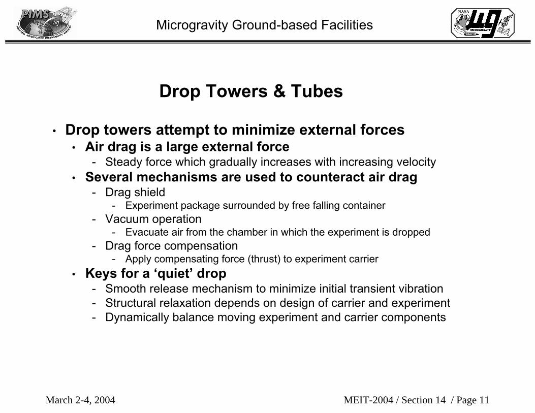
• Drop towers attempt to minimize external forces• Air drag is a large external force
- Steady force which gradually increases with increasing velocity• Several mechanisms are used to counteract air drag
- Drag shield - Experiment package surrounded by free falling container
- Vacuum operation- Evacuate air from the chamber in which the experiment is dropped
- Drag force compensation- Apply compensating force (thrust) to experiment carrier
• Keys for a ‘quiet’ drop - Smooth release mechanism to minimize initial transient vibration- Structural relaxation depends on design of carrier and experiment - Dynamically balance moving experiment and carrier components
Drop Towers & Tubes

March 2-4, 2004
Microgravity Ground-based Facilities
• NASA GRC 2.2 Second Drop Tower uses a drag shield
• Capture in an air bag
Drag Shield
Drag Shield
Experiment package
Velocity

March 2-4, 2004
Microgravity Ground-based Facilities
NASA GRC 2.2 Second Drop Tower
Experiment rig assemblyDrag shield preparation

March 2-4, 2004 MEIT-2004 / Section 14 / Page 14
Microgravity Ground-based Facilities
Vacuum Operation• Vacuum drop towers include:
• Zero Gravity Research Facility at NASA GRC- Capture in foam pellet container
• Zentrum für angewandte Raumfahrttechnologie und Mikrogravitation (ZARM) facility at University of Bremen, Germany
- Capture in foam pellet container
ZARM tower
exteriorExperiment capture in Zero Gravity Research Facility

March 2-4, 2004 MEIT-2004 / Section 14 / Page 15
Microgravity Ground-based Facilities
Drag Force Compensation• Japan Microgravity Center (JAMIC)
• Inner & outer capsule (i.e. drag shield)- Vacuum drawn between inner & outer capsules
• Acceleration added to outer capsule for drag compensation- Cold-gas jet
• Capture accomplished with air pressure then mechanical brake
JAMIC
This facility is now closed.

March 2-4, 2004 MEIT-2004 / Section 14 / Page 16
Microgravity Ground-based Facilities
Drop Tower Comparison• NASA GRC 2.2 Second Drop Tower
• 2.2 seconds 24.1 m 10-4 g
• ZARM Drop Tower• 4.74 seconds 123 m 10- 5 g
• NASA GRC Zero Gravity Research Facility• 5.18 seconds 145 m 10-5 g
• Japan Microgravity Center • 10 seconds 490 m 10-5 g
ZARM
This facility is now closed.

March 2-4, 2004 MEIT-2004 / Section 14 / Page 17
Microgravity Ground-based Facilities
Acceleration Environment Features of Drop Towers• Release
• Step change transition from 1-g to sub-milli-g level • Transition occurs over very short time that the mechanism
actually releases carrier
• Vibrations from release mechanism• The release transition is similar to ringing a bell
- Step change causes (unwanted) vibration in experiment carrier- The ‘bell ringing’ is damped by carrier and experiment mechanical design - Transients may persist for major portion of microgravity time
• Figure 2 illustrates acceleration levels in one axis• Transition from 1-g to microgravity • Oscillations during microgravity period (2.2 seconds)• Transients during “stop” at bottom

March 2-4, 2004 MEIT-2004 / Section 14 / Page 18
Microgravity Ground-based Facilities
1.400
-1 .400
-1 .200
-1 .000
-0 .800
-0 .600
-0 .400
-0 .200
0 .000
0 .200
0 .400
0 .600
0 .800
1 .000
1 .200
9 .05 .0 5 .5 6 .0 6 .5 7 .0 7 .5 8 .0 8 .5
accel data (g)
Data from the vertical axis in NASA GRC 2.2 Second Drop Tower facility.
0 .0 0 5
- 0 .0 0 5
- 0 .0 0 4
- 0 .0 0 3
- 0 .0 0 2
- 0 .0 0 1
0 .0 0 0
0 .0 0 1
0 .0 0 2
0 .0 0 3
0 .0 0 4
7 .55 .0 5 .5 6 .0 6 .5 7 .0
accel data (g) Low-g portion of dropComplete drop
1-g
0-g
Figure 2: Acceleration level for drop tower test
5-mg
0-mg
Time (sec)
Time (sec)
Acc
eler
atio
n le
vel (
g)
Acc
eler
atio
n le
vel (
g)

March 2-4, 2004 MEIT-2004 / Section 14 / Page 19
Microgravity Ground-based Facilities
Acceleration Environment Features of Drop Towers• Vibrations from experiment equipment operation, such as:
• Camera shutters• Film transport• Solenoid and relay actions• Pumps• Motor-driven fluid mixers• Figure 3 illustrates effects of equipment operation during drop
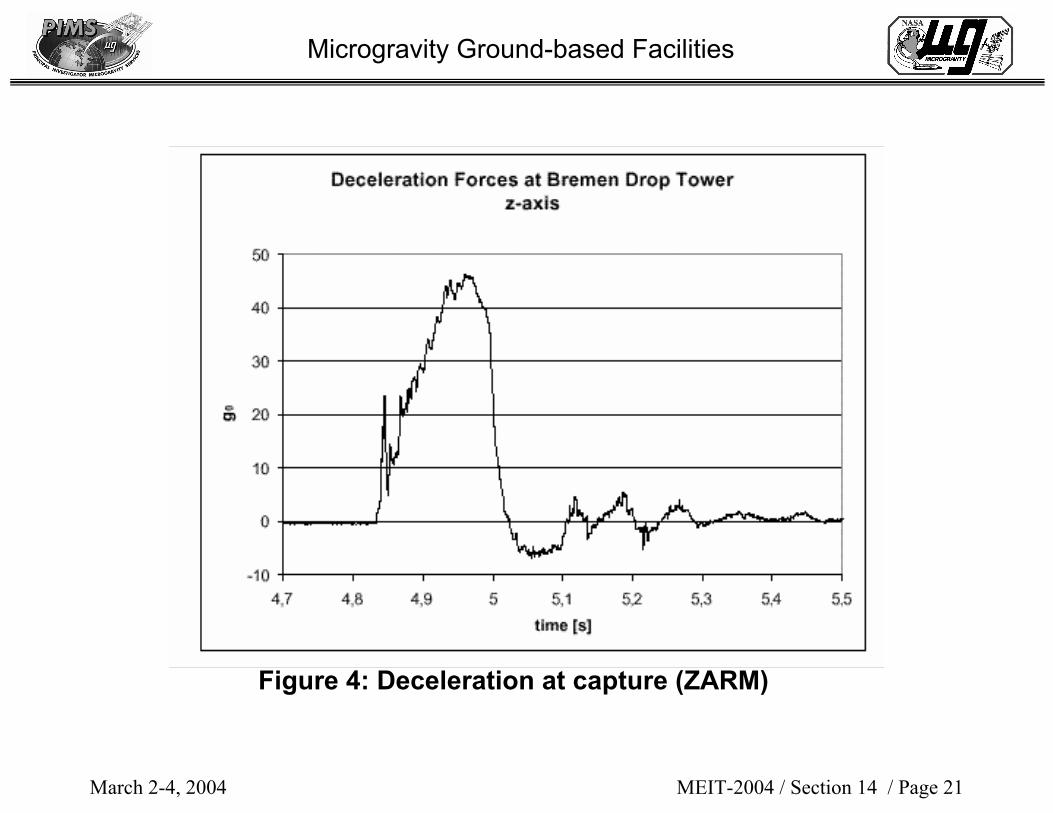
• High level of deceleration at capture • Levels depend on capture mechanism and final velocity • Figures 2 and 4 illustrate transients during “stop” at the bottom
of two different drop towers

March 2-4, 2004 MEIT-2004 / Section 14 / Page 20
Microgravity Ground-based Facilities
Figure 3: Power Spectral Density plot during drop (ZARM)(note: release disturbances not included)
Equipment operation
March 2-4, 2004 MEIT-2004 / Section 14 / Page 21
Microgravity Ground-based Facilities
Figure 4: Deceleration at capture (ZARM)
Peak > 40-g (!)

March 2-4, 2004 MEIT-2004 / Section 14 / Page 22
Microgravity Ground-based Facilities
Non-orbital flight platforms (~ 300 kph horizontal velocity)
• “Parabolic” trajectory• In reality, an elliptical path
• KC-135 aircraft (NASA)• Operated by NASA Johnson Space Center• Each parabola provides 15-20 seconds of reduced gravity
environment• Periodic free-fall interspersed with high-g pull-out• Approximately 40-50 parabolas per flight (campaign)
• Terrier-Black Brant sounding rocket• Achieves free-fall conditions on the order of 500 seconds after
motor burn-out • One of several types of sounding rockets

March 2-4, 2004 MEIT-2004 / Section 14 / Page 23
Microgravity Ground-based Facilities
Aircraft Facilities
SAMSLinear acceleration sensors and fiber optic gyro sensor
Parabolic Aircraft Rating System
Linear acceleration sensors and software processing
KC-135

March 2-4, 2004 MEIT-2004 / Section 14 / Page 24
Microgravity Ground-based Facilities
SAMSLinear acceleration sensors and
fiber-optic gyro sensor
Sounding Rockets
Terrier-Orion

March 2-4, 2004 MEIT-2004 / Section 14 / Page 25
Microgravity Ground-based Facilities
KC-135 Environment Characterization
• Figure 5 illustrates the KC-135 overall environment over multiple parabolas during a typical campaign
• Figure 6 is a detailed plot of the KC-135 environment during the reduced gravity portion of the parabola
• Figure 7 is the acceleration environment of a KC-135 parabola for the Spread Across Liquids (SAL) experiment.
• SAL test equipment was free-floated during the parabola• In that period, the acceleration environment was less than 0.15
milli-g, peak-to-peak

March 2-4, 2004 MEIT-2004 / Section 14 / Page 26
Microgravity Ground-based Facilities
Figure 5 - KC-135 acceleration environment over several parabolas

March 2-4, 2004 MEIT-2004 / Section 14 / Page 27
Microgravity Ground-based Facilities
Figure 6 - Low-g portion of KC-135 parabola

March 2-4, 2004 MEIT-2004 / Section 14 / Page 28
Microgravity Ground-based Facilities
Figure 7 - Acceleration environment for parabola in which an experiment was free-floated

March 2-4, 2004 MEIT-2004 / Section 14 / Page 29
Microgravity Ground-based Facilities
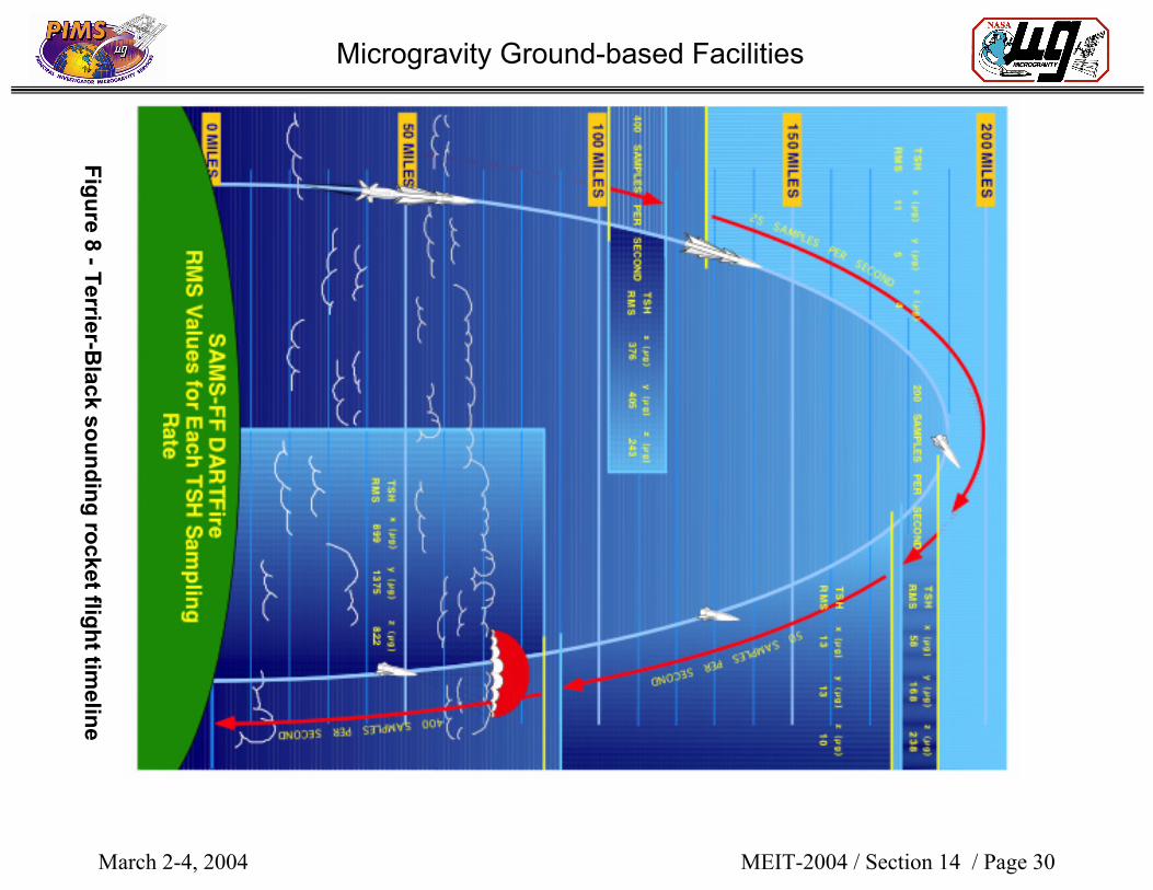
Sounding Rocket Environment Characterization
• Terrier-Black sounding rocket flight • Flight timeline is shown in Figure 8• DARTFire combustion experiment payload• SAMS data rate adjusted during flight
- Maximize data acquisition for limited storage capacity- Acquisition according to science requirements for low-frequency
measurements
• For period when sample rate was 25 samples per second:• Environment was less than 30 µg root sum square (RSS) • RSS power spectral density is shown in Figure 9
- Frequency domain characteristics match known disturbance sourcesinternal to the DARTFire equipment
- Intensified Multispectral Imager filter wheel operates at 5 Hz- Infrared Imager filter wheel operates at 1 Hz
March 2-4, 2004 MEIT-2004 / Section 14 / Page 30
Microgravity Ground-based Facilities
Figure 8 -Terrier-Black sounding rocket flight tim
eline

March 2-4, 2004 MEIT-2004 / Section 14 / Page 31
Microgravity Ground-based Facilities
Terrior-Orion Sounding Rocket
Microgravity Levels during Flight of DARTFire
Altitude Sample rate X Y Z(miles) (samples / sec) (ug RMS) (ug RMS) (ug RMS)
102 to 118 400 s/s 376 405 243118 to 190 25 s/s 11 5 4190 to 175 200 s/s 58 168 238175 to 85 50 s/s 13 13 1085 to 0 400 s/s 899 1375 822

March 2-4, 2004 MEIT-2004 / Section 14 / Page 32
Microgravity Ground-based Facilities
Figure 9 - Power spectral density during DARTFire experiment operations
Multispectralfilter wheel
IR imager filter wheel

March 2-4, 2004 MEIT-2004 / Section 14 / Page 33
Microgravity Ground-based Facilities
Summary
• Reduced-gravity environment • Does not have to be in space• Disturbances exist both in ground-based laboratories and in
space
• Acceleration environment of experiments • Measure and understand during ground-based testing• Basis for comparison as acceleration environment improves
- For example, as experiment moves from lab testing to drop tower to KC–135 to ISS

March 2-4, 2004 MEIT-2004 / Section 14 / Page 34
Microgravity Ground-based Facilities
References• Zero Gravity Research Facility
• http://microgravity.grc.nasa.gov/zero-g/index.html
• 2.2 Second Drop Tower• http://microgravity.grc.nasa.gov/drop2/
• ZARM Drop Tower• http://www.zarm.uni-bremen.de/main.htm
• ZARM Drop Tower Bremen - Users Manual, Version 28, April 2000• Microgravity Carrier Summary
• http://microgravity.msfc.nasa.gov/NASA_Carrier_User_Guide.pdf
• Ross, H. D. (2001) Microgravity Combustion, Academic Press