section 13205 bleach storage tanks - d.n. higginsdnhiggins.com/docs/rfq _14-6213-15 spec -...
TRANSCRIPT

13205-10
NCWRF BLEACH TANK REPLACEMENT
SECTION 13205
BLEACH STORAGE TANKS
PART 1 - GENERAL
1.1 SECTION INCLUDES
A. Furnish all labor, materials, equipment, and incidentals required to install, field test,
complete, and make ready for service vertical fiberglass reinforced plastic (FRP)
storage tank(s). The tanks shall be designed for use with 12.5-15 percent commercial
sodium hypochlorite (NaOCl) solution.
B. Chemical storage tank shall be furnished complete with all associated appurtenances
such as hardware, anchorage, piping, piping supports, manways, safety ladder, top
hand railing, reverse float level indicator, connection for ultrasonic level indicators,
etc., as specified herein or as otherwise required.
C. It is the intent of this Specification to obtain an installation complete in every necessary
detail whether or not covered by the Specification. Any omission of required
equipment from the Specification shall not relieve the manufacturer of his
responsibility to satisfy this intent.
D. Any drawings provided are for tank dimensions and nozzle orientations only and shall
not be used for tank construction.
E. Piping shall be as shown on the drawings, specified herein, and as required to match
existing conditions.
1.2 REFERENCE SPECIFICATIONS, CODES, AND STANDARDS
A. U.S. Department of Commerce Voluntary Product Standard PS-15-69
B. ASTM C 581 - Standard Practice for Determining Chemical Resistance of
Thermosetting Resins Used in Glass-Fiber-Reinforced Structures Intended for Liquid
Service
C. ASTM C 582 - Standard Specification for Contact-Molded Reinforced
Thermosetting Plastic (RTP) Laminates for Corrosion-Resistant Equipment
D. ASTM D 2310 - Standard Classification for Machine-Made “Fiberglass” (Glass-
Reinforced Thermosetting-Resin) Pipe
E. ASTM D 2471-71 - Standard Test Method for Gel Time and Peak Exothermic
Temperature of Reacting Thermosetting Resins
F. ASTM D 2517 - Standard Specification for Reinforced Epoxy Resin Gas Pressure Pipe
and Fittings
G. ASTM D 2563 - Standard Practice for Classifying Visual Defects in Glass-Reinforced
Plastic Laminate Parts
H. ASTM D 2583 Standard Test Method for Indentation Hardness of Rigid Plastics by
Means of a Barcol Impressor

13205-11
NCWRF BLEACH TANK REPLACEMENT
I. ASTM D 2584 Standard Test Method for Ignition Loss of Cured Reinforced Resins
(Burn Test)
J. ASTM D 2996 Standard Specification for Filament-Wound “Fiberglass” (Glass Fiber-
Reinforced Thermosetting-Resin) Pipe
K. ASTM D 3299 Standard Specification for Filament-Wound Glass-Fiber-Reinforced
Thermoset Resin Corrosion-Resistant Tanks
L. ASTM D 3982 Standard Specification for Custom Contact Molded “Fiberglass” (Glass
Fiber-Reinforced Thermosetting Resin) Duct and Hoods
M. ASTM D 4021 Standard Specification for Glass Fiber-Reinforced Polyester
Underground Petroleum Storage Tanks
N. ASTM D 4097 - Standard Specification for Contact-Molded Glass Fiber-Reinforced
Thermoset Resin Corrosion-Resistant Tanks
O. ASME Section X Vessel Code
P. ASME/ANSI RTP-1 Reinforced Thermoset Plastic Corrosion-Resistant Equipment
Q. ASME Code for Pressure Piping B31.3, Non-Metallic Section
R. ICBO Report ER-4055 Class 5 FRP Duct Systems for Removal of Nonflammable
Corrosive Fumes and Vapors.
1.3 SUBMITTALS
A. Shop Drawings:
1. The Contractor shall be responsible for coordinating all interfaces with related
mechanical, structural, electrical and instrumentation and control work. The
Contractor shall be responsible for providing all accessory equipment and all
work associated with installation of the equipment.
2. Shop Drawings for the FRP tanks shall include as a minimum the following:
a. Manufacturer’s catalog information, descriptive literature,
specifications, and materials of construction and chemical resistance.
b. Resin and materials of construction including thickness of each layer.
c. Service Conditions: Chemical environment and temperature.
d. Details of FRP ladders, grating and grating support systems and
handrails.
e. Details of tie-down systems for all storage tanks and appurtenances.
f. Dimensions of tanks, fittings, pipe connections, manways and
appurtenances.
g. Total operating weight of each tank and fittings.
h. Dimensions, orientation and location of nozzles showing details of
construction and attachment to tank.
i. Complete, detailed instructions on handling and installation of tanks.
j. Submit a data sheet from resin manufacturer listing nomenclature,
composition and characteristics of the resin.
k. Submit a copy of manufacturer’s valid ASME RTP-1 Certificate of
Authorization.
13205-12
NCWRF BLEACH TANK REPLACEMENT
3. Contractor shall submit detailed fabrication drawings including design
calculations for structural design of tank, shell, lifting and tie down systems,
tank anchor lugs and anchor bolts, signed and sealed by a professional Engineer
licensed in the State of Florida. Design calculations shall be submitted with the
shop drawing. Submission of design calculations is intended to indicate that the
equipment was designed by a qualified individual. Design calculations will not
be reviewed for completeness or correctness. The design of the tanks shall be
the responsibility of the manufacturer.
4. Contractor shall submit fabricator’s recommended bolt torques for all bolted
FRP connections.
B. Post-Fabrication Submittals
1. Submit complete installation, operation and maintenance manuals including as-
built drawings.
1.4 PRODUCT DELIVERY, STORAGE, AND HANDLING
A. Be responsible for the safe transportation to the job site, including any freight cost and
necessary permits, handling, and open air storage of the tanks and other materials
purchased as specified in this Section.
B. Tanks delivered to the job site shall be inspected immediately by CONTRACTOR for
damage, unloaded and stored with a minimum of handling. Comply with
manufacturer's recommendations in handling and storing tanks. Tanks shall be shipped
empty; all interior components shall be shipped separately.
C. In general, tanks shall be:
1. Checked and tied down to prevent being blown by wind.
2. Vented to allow for temperature changes that may affect their integrity.
3. Provided with opening protection to exclude foreign matter.
D. The manufacturer shall protect all flange faces and any fragile appurtenances or sub-
assemblies, with proper packaging, in order to prevent one piece from impacting with
another, and by crating or other means for shipment.
E. Impact of tools or other heavy objects shall be avoided. Impacts may result in a
fracture of the inner lining and affect the service life of the equipment.
F. Large sub-assemblies should be supported during unloading to prevent excessive
deflection and overstressing.
G. Equipment and materials shall be stored so as to keep free from moisture, damage, and
deterioration.
H. Tanks shall be protected, by padding or bracing, from banding or ropes used in
shipment. No chains are to be used to secure any tanks in transportation.
13205-13
NCWRF BLEACH TANK REPLACEMENT
I. Tanks shall be clearly marked for any precautions in handling and transportation.
1.5 RESPONSIBILITIES
A. The tank manufacturer shall be fully responsible for the structural design, structural
integrity, and water tightness of the tanks including all anchorage and connections..
1.6 MANUFACTURER’S SERVICE REPRESENTATIVE
A. The services of a qualified manufacturer's technical representative who shall
adequately inspect the proper installation of each tank and supply a written installation
certification to the contractor. Initial start-up and operation is not required by the tank
representative.
1.7 QUALITY ASSURANCE
A. Manufacturer: The materials covered by these Specifications are intended to be
standard equipment of proven reliability and as manufactured by reputable
manufacturers having experience in the production of such equipment. The equipment
furnished shall be designed, constructed, and installed in accordance with the best
practices and methods and shall operate satisfactorily when installed and operated per
manufacturer's recommendations. FRP tanks shall be manufactured by one of the
following firms, in strict compliance with those specifications. No alternate
manufacturers will be considered.
1. BELCO Manufacturing Co., Inc .
2. Diamond Fiberglass
3. Plas-Tanks Industries, Inc.
B. Qualifications
1. Fabricator’ s Quality Assurance Supervisor: Minimum of 5 year’s experience
with the fabrication of fiberglass structures.
2. Designer: Registered professional engineer licensed in the state of Florida.
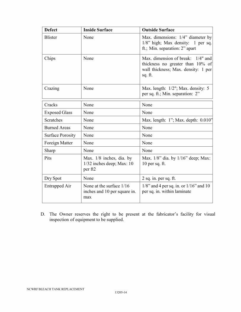
C. Inspection and Testing Requirements: The Owner reserves the right to reject delivery
of any or all pieces of equipment found, upon inspection, to have any or all of the
following: blisters, chips, crazing, exposed glass, cracks, burned areas, dry spots,
foreign matter, surface porosity, sharp discontinuity or entrapped air at the surface of
the laminate. Any item which does not satisfy the tolerances as below shall be
rejected:
13205-14
NCWRF BLEACH TANK REPLACEMENT
Defect Inside Surface Outside Surface
Blister None Max. dimensions: 1/4” diameter by
1/8” high; Max density: 1 per sq.
ft.; Min. separation: 2” apart
Chips None Max. dimension of break: 1/4" and
thickness no greater than 10% of
wall thickness; Max. density: 1 per
sq. ft.
Crazing None Max. length: 1/2"; Max. density: 5
per sq. ft.; Min. separation: 2”
Cracks None None
Exposed Glass None None
Scratches None Max. length: 1”; Max. depth: 0.010”
Burned Areas None None
Surface Porosity None None
Foreign Matter None None
Sharp
Discontinuity
None None
Pits Max. 1/8 inches, dia. by
1/32 inches deep; Max: 10
per ft2
Max. 1/8” dia. by 1/16” deep; Max:
10 per sq. ft.
Dry Spot None 2 sq. in. per sq. ft.
Entrapped Air None at the surface 1/16
inches and 10 per square in.
max
1/8” and 4 per sq. in. or 1/16” and 10
per sq. in. within laminate
D. The Owner reserves the right to be present at the fabricator’s facility for visual
inspection of equipment to be supplied.

13205-15
NCWRF BLEACH TANK REPLACEMENT
PART 2 - PRODUCTS
2.1 GENERAL
A. The manufacturer is responsible for the coordination and selection of corrosion
resistant materials for the chemical herein specified. The chemical storage tank
manufacturer shall become familiar with the characteristics of the specified chemical
and guarantee the suitability of the materials used in manufacturing of the tanks and
accessories. The Contractor and manufacturer shall include all features as necessary
for satisfactory operation of the systems for the specified chemical.
B. Tank capacity (volume) specified shall include only that volume in the straight shell
below the overflow pipe invert elevation and above the pump suction connection. At
least 4 inches of freeboard shall be provided between the invert elevation of the
overflow pipe and the top of the straight shell.
C. Storage tanks shall be made of materials that can withstand the maximum storage
temperature. Chemical properties are as follows:
Parameter Sodium Hypochlorite
CAS Number: 7681-52-9
Storage Concentration: 12.5 – 15%
pH: 12.0
Boiling Point, oF: 212
Chemical Specific Gravity: 1.05
Design Specific Gravity: 1.9
Design Temperature, oF: 120
D. The Contractor and tank manufacturer shall be fully responsible for the structural
design and integrity and water-tightness of the tanks, including all anchorages and
connections.
2.2 TANK MATERIALS AND CONSTRUCTION
A. Tank shall be mounted on level concrete housekeeping pads. Flat bottom tanks shall be
provided with a flush bottom drain. The concrete housekeeping pad shall be provided
with a notch in the pad to accommodate the flush bottom drain. For replacement tanks
verify that existing notch is adequate for new tank; modify and/or provide notch as
necessary.
B. Tanks shall be designed per ASME RTP-1, Part 3 (3A or 3B as applicable). Vessel
major components, shell joints (secondary bond overlays), flanged nozzles, manways
and reinforcement of cutouts are fabricated to ASME RTP-1 Latest Edition, Section 4-
300 thru 4-600 as applicable using Type I, Type II, or Type X laminates. Corrosion
liner thickness shall be excluded from the structural calculations. ASME Stamp is Not
Required.

13205-16
NCWRF BLEACH TANK REPLACEMENT
C. All tanks and related FRP accessories shall be fabricated in a controlled and well
ventilated structure protected from weather and temperature extremes. Entire
fabrication, curing and assembly process of any piece of FRP equipment shall be
indoors.
D. Resin:
1. The resins used in fabrication shall be premium grade vinyl ester such as
Ashland Chemical’s Derakane 411 or Hetron 922, or equal.
a. For tanks in sodium hypochlorite service, the corrosion liner resin
shall be a premium grade brominated vinyl ester, such as Hetron 992, or
equal. The structural layer resin shall be Hetron 922 or equal.
2. For applications requiring fire-retardant resin, the Fabricator’s fire retardant
version of the resins noted in shall be used.
3. The resin used shall not contain any fillers, pigments, dyes, or colorants, which
may interfere with visual inspection of laminate quality, except as required for
viscosity control. The limit of filler shall be 5 percent by weight of thrixotropic
agent, Cab-O-Sil or equal, and shall not interfere with visual inspection. No
fillers or bulking agents shall be used in the exterior structural layer to decrease
the glass loading ratio.
a. Vessels fabricated for sodium hypochlorite service must be fabricated
without the use of thixotropic agents, as the sodium hypochlorite reacts
with the thixotropic agents, compromising the corrosion resistance of
the vessel.
4. The cure system used for the resin shall be in accordance with the resin
Fabricator’s current recommendations. Proper curing of the resin is the
Fabricator’s responsibility. All products fabricated to this specification shall be
cured to at least 90% of the minimum Barcol hardness specified by the resin
Fabricator. (Note: The use of paraffin in the resin or the use of Nexus veil may
lower the Barcols below the resin Fabricator’s specifications).
a. Vessels fabricated for sodium hypochlorite service must be fabricated
utilizing a BPO/DMA cure system for the corrosion liner and either
BPO/DMA or MEKP catalyst system for the structural layer.
5. The chemical-resistant surface, interior or exterior, shall not be acetone
sensitive. A wax containing resin coating, formulated according to the resin
Fabricator’s most recent recommendations, must be applied over any interior
secondary bonds to achieve an air-inhibited cure.
E. Reinforcement
1. One layer of Nexus surfacing veil shall be used to reinforce the inner surface.
Thickness of the resin rich inner surface shall be 0.020” to 0.025”. Total
thickness of the inner surface and interior layer shall be not less than 0.100”.
Nexus shall be Style 100-10 Aperturned 1.5 oz. Dacron polyester fiber 12-16
mils thick as manufactured by Burlington Glass Fabric Company.
13205-17
NCWRF BLEACH TANK REPLACEMENT
2. The interior layer shall be applied in a minimum of two passes of chopped
strand roving using automatic fabrication equipment which controls raw
material deposition to rotating molds through the use of digital readout
programmable controllers for raw material use verification. Resin content of
the interior layer shall be 70%, plus or minus 5%.
a. A double ply Nexus surfacing veil is required for vessels in sodium
hypochlorite service, due to the aggressive corrosion characteristics of
sodium hypochlorite. The application of the second ply of veil will
increase the inner surface thickness from 0.020” to 0.035”. The interior
layer reinforcement for sodium hypochlorite shall be boron free ECR
type glass as manufactured by Owens Corning ADVANTEX.
3. Structural portion of vessel wall shall utilize continuous winding glass for hoop
properties (and unidirectional glass as required for additional axial properties)
interspersed with automatically applied chopped glass and resin. Resin to glass
content shall be 50/50 plus or minus 5%.
F. All joints between tank components shall be covered by layup. Internal joints shall be
provided with a resin-rich surface veil overlay, reinforced with chemically resistant
surfacing material.
G. The tank top shall be domed with openings and connections as specified herein. The
tank top shall be able to support a 250-pound load on a 4-inch by 4-inch area, and other
loads as specified herein. Tank bottom to side-wall connection shall be seamless.
H. Structural Design:
1. The Contractor shall assign to the FRP tank manufacturer full responsibility for
the complete structural design of each FRP tank.
a. All tanks located outdoors shall be designed for anchorage and wind
loads in accordance with ASCE 7 as follows:
Wind Speed = 175 MPH
Exposure Category = C
Importance Factor = 1.15
b. Design for Seismic forces
Ground Acceleration: Per ASCE 7
Occupancy Class: 3
Importance Factor: 1.25
Site Class: D
Project Location: Zip Code 34110
2. All tanks shall be capable of withstanding a surcharge of 12 inches water
column when full and a negative pressure of 6 inches water column when
empty.
3. Tie-down Ring/Mounting Lugs: FRP or Type 316 stainless steel (integrally
assembled to tank). Provide three to one safety factor with an increase in
allowable stress of one-third against seismic forces as set forth for applicable
zoned seismic area. Mounting ring / tie down lugs shall be factory assembled
as part of the tank construction.
13205-18
NCWRF BLEACH TANK REPLACEMENT
4. Furthermore, anchor lugs for all tanks installed outdoors and indoors shall be
adequate to withstand flotation.
5. The tank manufacturer shall design anchors for securing the tanks via the
anchor lugs to concrete housekeeping pads. The anchors shall be fabricated of
Hastelloy-C or titanium or 316 stainless steel. The concrete housekeeping pad
will have a compressive strength of 4,000 psi at 28 days.
6. The Contractor shall be responsible for furnishing and installing the anchors.
2.3 CONNECTIONS AND ACCESSORIES
A. Connections: All connections/openings shall be flanged in accordance with ANSI
B16.5 Class 150 and provided with flanged gasket. Flanged connections, nozzles, and
openings shall be FRP gusseted and flat face. Threaded connections are not allowed,
no exceptions.
B. Nozzles: All nozzles for Sodium Hypochlorite service shall be flush-type per ASTM
D3299 or ASTM D4097. Penetrating-type installation is not allowed for Sodium
Hypochlorite service. All nozzles shall be gusseted.
C. Fill Lines: All pipe supports, hardware, accessories, etc., shall be provided. Vertical
piping into the tanks shall be supported at minimum every 2.5 feet on-center except
where otherwise indicated on the Drawings, and shall be parallel to the tank wall and
not less than 3 inches from the tank wall.
D. Pump Suctions: All pipe supports, hardware, accessories, etc. shall be provided.
E. Vent Lines: Vent lines shall be top-mounted. Vent lines shall be supplied and
furnished by the Contractor as required or as directed by the Engineer. Vent lines shall
be as specified herein and as indicated on the Drawings. Vents shall be covered with
fiberglass fibermesh screen.
F. Overflow Line: The tanks shall be provided with an overflow pipe with pipe supports
as specified and as indicated on the Drawings.
G. Drain Line: The tanks shall be provided with a drain pipe as specified and as indicated
on the Drawings. Drain connection shall be full-invert type connection and flush to the
bottom of the tank.
H. Pipe Supports and Accessories: Pipe supports, hardware, and accessories on tanks shall
be provided by the tank manufacturer. Vertical piping and electrical conduit from the
tanks shall be supported every 2.5 feet and shall be parallel to the tank wall and not
more than 6 inches from the tank wall. All supports, hardware, and accessories shall be
fiberglass or 316 Stainless Steel. Provide pipe support clips or brackets to secure all
vertical piping and conduit to the exterior of the tank. Pipe support clips shall be
laminated to the tank exterior wall and designed for 150 mph winds.

13205-19
NCWRF BLEACH TANK REPLACEMENT
I. Level Sensor/Element: The tanks shall be provided with a flange outlet for an
ultrasonic level sensor and a suitable blind flange. The tank manufacturer shall
coordinate the mounting and connecting requirements with the Contractor and the
requirement for the transducer.
J. Reverse Float Tank Level Gauge:
1. Each tank shall be equipped with a reverse float visual liquid level gauge with
pipe supports.
2. The gauge assembly shall be comprised of a float mounted inside the tank, a
cable and pulley system, and a clear PVC or polycarbonate sight tube with
calibrations marked in inches from the bottom of the gage.
3. The tube shall be mounted on outside the tank and a red or orange visual
indicator within the sight tube.
4. Adjacent to the level gage, provide a calibration strip marked in gallons.
5. All components of the reverse float visual liquid level gauge shall be
compatible with the chemical stored within the tank. Cable shall be Teflon
(PTFE) or equal.
6. The reverse float level gauge shall be as manufactured by Precision Tank
Gauge, Inc., or approved equal.
K. Manways: Provide 24-inch diameter top manway. Provide 30-inch diameter side
manway. Manways shall be flat-faced flanged manway with gasket and blind flange
that are chemically resistant for internal access. Flange hardware (i.e., bolts, washers,
nuts, etc.) shall be 316 stainless steel. Gaskets shall be 1/8 inch thick full face Viton or
EPDM gaskets.
L. Access Ladder:
1. Tanks shall be equipped with an exterior access ladder with safety cage for
access to the top of tank.
2. Construction: Heavy-duty fiberglass reinforced vinyl ester capable of a 250
pound load. Ladder shall be 18-inches between side rails, 12-inches between
rungs. Rungs shall be non-slip.
3. Ladder to meet OSHA requirements and be compatible with chemical service.
4. FRP angle clips shall be furnished for mounting the bottom of the ladder to the
concrete pad.
5. The tank top shall be equipped with ladder clips to bolt ladder handrails thereto.
6. Ladder to be manufactured by Ultra Fiberglass Systems, or approved Equal.
M. Lifting Lugs: The tank shall be provided with a minimum of four lifting lugs, three of
them around the top edge of the tank and one at the base of the tanks. Lugs shall be 316
stainless steel. Lifting lugs shall be capable of withstanding weight of an empty tank
with a safety factor of 3 to 1.
13205-20
NCWRF BLEACH TANK REPLACEMENT
N. Certification Label: The tank shall be provided with a permanently attached label
providing the following information:
1. Type of material stored
2. Concentration of material stored
3. Specific gravity
4. Design temperature
5. Type of liner resin and reinforcement
6. Type of surface veil
7. Tank capacity
8. Weight Empty
9. Diameter
10. Sidewall Height
11. Manufacturer
12. Date of manufacture
13. Serial Number
O. Platform and Handrail: Tank manufacturer shall design and furnish tank with a half-
round platform with FRP grating and perimeter FRP handrail at the top of the tank.
1. The platform shall be designed to support a concentrated live load of 400
pounds on an area of 36 square inches or a uniform live load of 50 pounds per
square foot, whichever greater. Deflection shall be limited to ¼” or span
divided by 200.
2. Design Handrail per IBC/UBC; concentrated load of 200 lb (any location; any
direction); Uniform load of 50 lb per foot (top rail only; any direction)
3. Platform and handrail to be manufactured by Ultra Fiberglass Systems, or
approved Equal.
2.4 FIBERGLASS REINFORCED PLASTIC STORAGE TANK SCHEDULE
A. Contractor shall provide tanks in accordance with Tables 13205-1 and 2.
PART 3 - EXECUTION
3.1 INSTALLATION
A. The Contractor shall remove and dispose of the existing tank. Existing tank is leaking.
Sodium hypochlorite solution may be in the interstitial space.
B. The Contractor shall furnish and install the Fiberglass Reinforced Plastic storage tanks,
and related items in accordance with the manufacturers' recommendations.
C. All piping, valves, fittings, conduit, wiring, etc., required to interconnect system
components shall be furnished and installed by the Contractor. Unless otherwise noted
on piping schedule, piping shall be Schedule 80 CPVC.
13205-21
NCWRF BLEACH TANK REPLACEMENT
3.2 TANK BOTTOM BUFFER PAD
A. Liquid grout such as grout, epoxy, etc. MUST NOT be used under flat bottom tanks.
B. For each tank, install a minimum of 3 layers of 30 pound roofing felt paper between
the concrete housekeeping pad and the flat bottom storage tank, or in accordance with
the tank manufacturer’s recommendations.
C. When applying the roofing felt or manufacturer’s recommended padding, there shall be
no overlaps or wrinkles which cause raised ridges under the tank bottom.
3.3 FACTORY COATINGS – OUTDOOR EXPOSURE
A. This article applies to tanks that are subject to permanent outdoor exposure.
B. The non-process side layer shall be factory finished with two white pigmented exterior
gel coats containing ultraviolet (UV-9) light inhibitors.
3.4 TESTING
A. Upon completion of installation of tank and prior to connecting piping, the Contractor
shall provide blind flanges or other suitable plugs for all openings in the tank, fill tanks
with clean water provided by the Owner from a source approved by the Engineer and
conduct a leakage test as specified herein. Tanks shall be filled up to the top of the
straight shell of the tank and left to sit over a 2-day test period. There shall be no
leakage over the test period. Leakage around openings in the tank shall be stopped by
tightening nuts and bolts or replacing gaskets as required. Upon satisfactory
completion of leakage test, Contractor shall drain the tanks and dispose of water in a
suitable manner.
B. Upon completion of water test, Owner will fill tank with bleach. After 2-days,
contractor shall check for leaks.
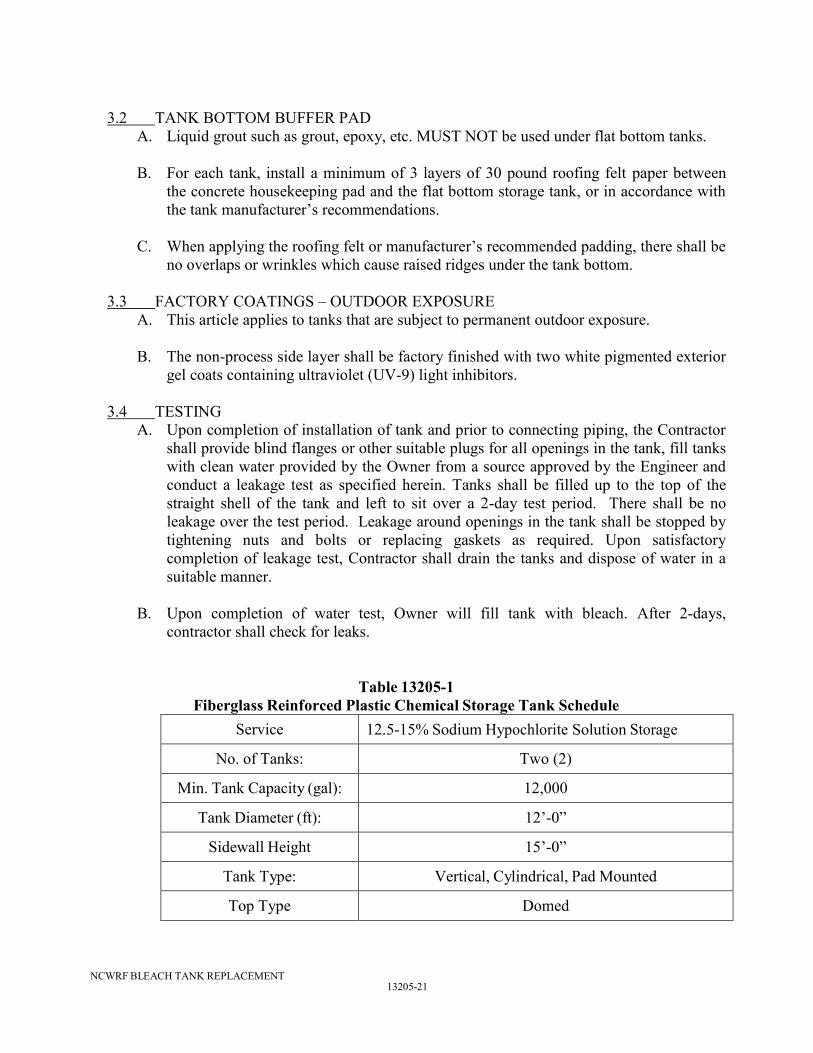
Table 13205-1
Fiberglass Reinforced Plastic Chemical Storage Tank Schedule
Service 12.5-15% Sodium Hypochlorite Solution Storage
No. of Tanks: Two (2)
Min. Tank Capacity (gal): 12,000
Tank Diameter (ft): 12’-0”
Sidewall Height 15’-0”
Tank Type: Vertical, Cylindrical, Pad Mounted
Top Type Domed
13205-22
NCWRF BLEACH TANK REPLACEMENT
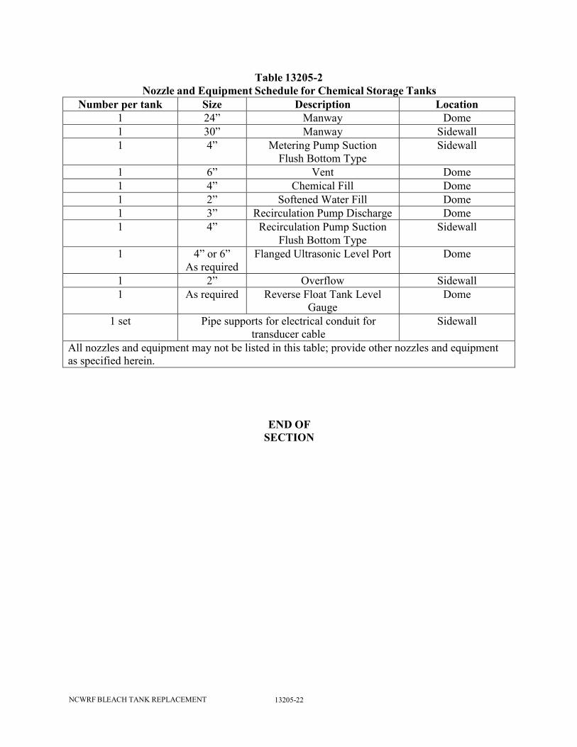
Table 13205-2
Nozzle and Equipment Schedule for Chemical Storage Tanks
Number per tank Size Description Location
1 24” Manway Dome
1 30” Manway Sidewall
1 4” Metering Pump Suction
Flush Bottom Type
Sidewall
1 6” Vent Dome
1 4” Chemical Fill Dome
1 2” Softened Water Fill Dome
1 3” Recirculation Pump Discharge Dome
1 4” Recirculation Pump Suction
Flush Bottom Type
Sidewall
1 4” or 6”
As required
Flanged Ultrasonic Level Port Dome
1 2” Overflow Sidewall
1 As required Reverse Float Tank Level
Gauge
Dome
1 set Pipe supports for electrical conduit for
transducer cable
Sidewall
All nozzles and equipment may not be listed in this table; provide other nozzles and equipment
as specified herein.
END OF
SECTION