section 11 other abs actuators - toyota celicagt4.mwp.id.au/toyota manuals/mechanics...
TRANSCRIPT
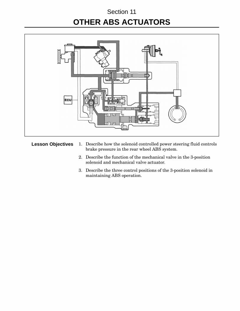
1. Describe how the solenoid controlled power steering fluid controls
brake pressure in the rear wheel ABS system.
2. Describe the function of the mechanical valve in the 3−position
solenoid and mechanical valve actuator.
3. Describe the three control positions of the 3−position solenoid in
maintaining ABS operation.
Section 11
OTHER ABS ACTUATORS
Lesson Objectives
Section 11
154 LEXUS Technical Training
Toyota uses several types of ABS actuators, each differs in how the
modulation of pressure is accomplished. The function of sensors and
ECU control already discussed in Section 8, do not differ.
The 3−position solenoid valve uses a 3−position valve, electrical coil and
check valve. As current flows through the solenoid windings, it creates
a magnetic field around the 3−position valve causing it to move toward
the center of the coil compressing the return spring. Current from the
ABS ECU is switched in three steps; 0 amps, 2 amps and 5 amps in
order to control the strength of the magnetic force in the coil.
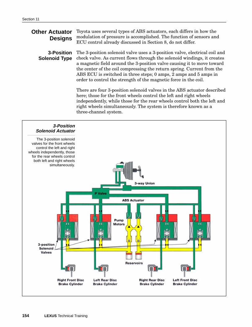
There are four 3−position solenoid valves in the ABS actuator described
here; those for the front wheels control the left and right wheels
independently, while those for the rear wheels control both the left and
right wheels simultaneously. The system is therefore known as a
three−channel system.
3-PositionSolenoid Actuator
The 3-position solenoidvalves for the front wheels
control the left and rightwheels independently, those
for the rear wheels controlboth left and right wheels
simultaneously.
Other ActuatorDesigns
3-PositionSolenoid Type
Actuator Types
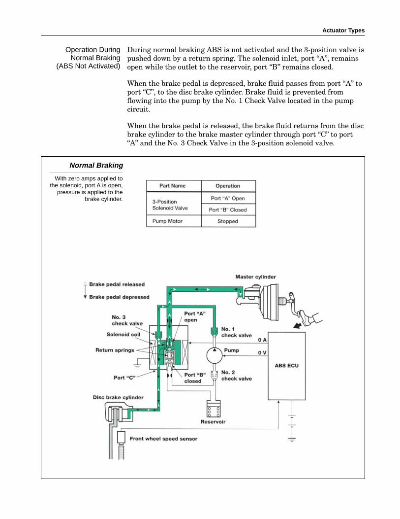
During normal braking ABS is not activated and the 3−position valve is
pushed down by a return spring. The solenoid inlet, port �A", remains
open while the outlet to the reservoir, port �B" remains closed.
When the brake pedal is depressed, brake fluid passes from port �A" to
port �C", to the disc brake cylinder. Brake fluid is prevented from
flowing into the pump by the No. 1 Check Valve located in the pump
circuit.
When the brake pedal is released, the brake fluid returns from the disc
brake cylinder to the brake master cylinder through port �C" to port
�A" and the No. 3 Check Valve in the 3−position solenoid valve.
Normal Braking
With zero amps applied tothe solenoid, port A is open,
pressure is applied to thebrake cylinder.
Operation DuringNormal Braking
(ABS Not Activated)

Section 11
156 LEXUS Technical Training
When the ECU determines that a wheel is about to lockup, it switches
to the holding mode to stop the increase in hydraulic pressure. As the
pressure inside the disc brake cylinder is reduced or increased, and the
speed sensor indicates that the speed is at the target level, the ECU
supplies a 2 ampere signal to the solenoid coil to hold the pressure in
the disc brake cylinder at that level.
When the current supplied to the solenoid coil is reduced from 5
amperes (in the pressure reduction mode) to 2 amperes (in holding
mode), the magnetic force generated in the solenoid coil also decreases.
The 3−position solenoid valve then moves down to the middle position
by the force of the return spring, closing port �B".
With the ECU holding Port A closed, and pedal pressure closing check
valves #1 & #3, brake caliper pressure holds steady, and cannot be
increased.
“Holding” Mode
Two amps applied to thesolenoid, Port A and Port B
are closed, pressure remainsconstant.
“Holding” Mode
Actuator Types
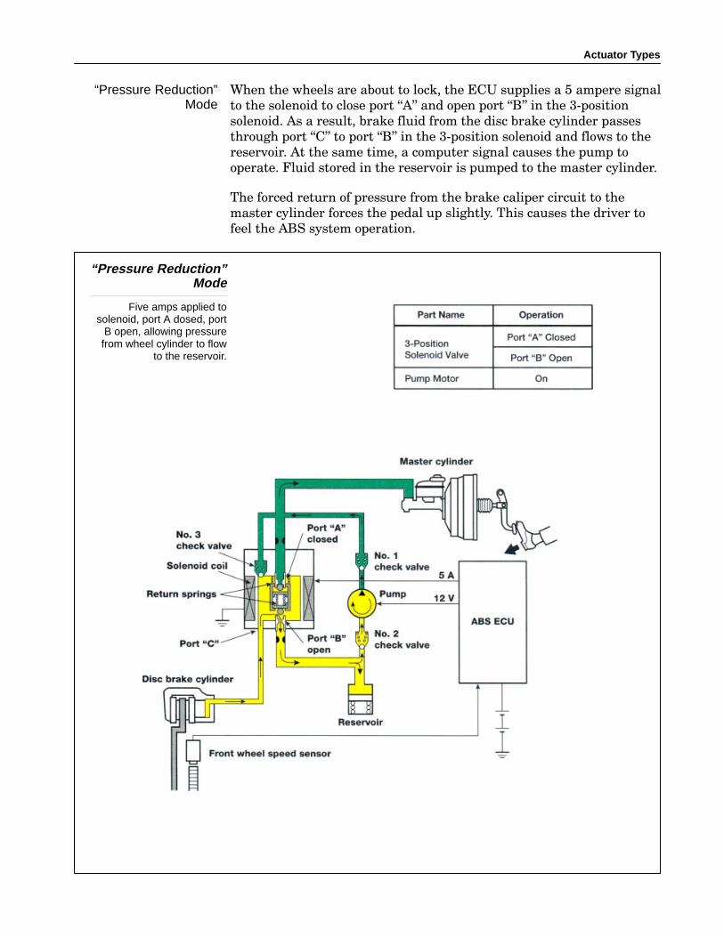
When the wheels are about to lock, the ECU supplies a 5 ampere signal
to the solenoid to close port �A" and open port �B" in the 3−position
solenoid. As a result, brake fluid from the disc brake cylinder passes
through port �C" to port �B" in the 3−position solenoid and flows to the
reservoir. At the same time, a computer signal causes the pump to
operate. Fluid stored in the reservoir is pumped to the master cylinder.
The forced return of pressure from the brake caliper circuit to the
master cylinder forces the pedal up slightly. This causes the driver to
feel the ABS system operation.
“Pressure Reduction”Mode
Five amps applied tosolenoid, port A dosed, port
B open, allowing pressurefrom wheel cylinder to flow
to the reservoir.
“Pressure Reduction”Mode

Section 11
158 LEXUS Technical Training
When the pressure in the disc brake cylinder needs to be increased to
apply more braking force, the ECU stops sending current to the
solenoid coil. This opens port �A" of the 3−position valve and closes port
�B". This allows the fluid in the master cylinder to pass from port �C"
in the three−position solenoid valve to the disc brake cylinder. The
hydraulic pressure increase rate is controlled by the repetition of the
pressure increase and holding modes.
Brake caliper pressure will increase as long as the driver continues to
apply pedal pressure.
“Pressure Increase”Mode
Zero amps applied tosolenoid, Port A
open allowingpressure application
at wheel cylinder.
“Pressure Increase”Mode
Actuator Types
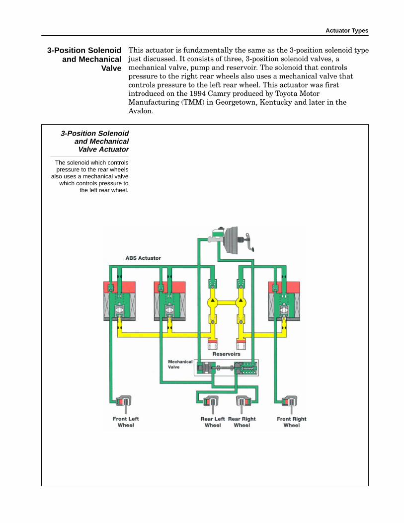
This actuator is fundamentally the same as the 3−position solenoid type
just discussed. It consists of three, 3−position solenoid valves, a
mechanical valve, pump and reservoir. The solenoid that controls
pressure to the right rear wheels also uses a mechanical valve that
controls pressure to the left rear wheel. This actuator was first
introduced on the 1994 Camry produced by Toyota Motor
Manufacturing (TMM) in Georgetown, Kentucky and later in the
Avalon.
3-Position Solenoidand MechanicalValve Actuator
The solenoid which controlspressure to the rear wheels
also uses a mechanical valvewhich controls pressure to
the left rear wheel.
3-Position Solenoidand Mechanical
Valve

Section 11
160 LEXUS Technical Training
The mechanical valve consists of two sets of cylinders and pistons and
a plunger to link their movement. Piston A monitors the pressure from
the master cylinder on its left side and monitors pressure to the right
rear brake circuit from the 3−position solenoid valve on its right side.
Piston A moves based on differences in pressure since piston surface
areas are equal.
Any movement of piston A is traced by piston B through the plunger. In
addition a spring loaded valve opens and closes the master cylinder
passage to the left rear brake. Piston B is spring loaded to the left
which leaves the valve unseated and the fluid path open.
Mechanical Valve
This valve controls pressureto the left rear brake
eliminating the need foranother solenoid.
The pressure increase mode is also the normal braking position for
brake operation without ABS, as shown in the illustration above.
Pressure from the master cylinder is equal to the pressure coming
through the 3−position solenoid to the right rear brake cylinder. Piston
A does not move and is held to the left by the spring acting on piston B.
Pressure increase comes from the master cylinder through the brake
pedal pressure.
Mechanical ValveConstruction
Pressure Increase Mode
Actuator Types
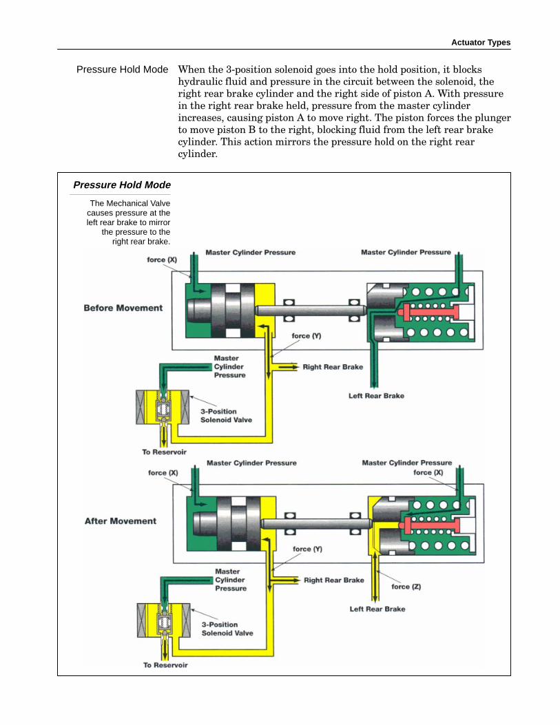
When the 3−position solenoid goes into the hold position, it blocks
hydraulic fluid and pressure in the circuit between the solenoid, the
right rear brake cylinder and the right side of piston A. With pressure
in the right rear brake held, pressure from the master cylinder
increases, causing piston A to move right. The piston forces the plunger
to move piston B to the right, blocking fluid from the left rear brake
cylinder. This action mirrors the pressure hold on the right rear
cylinder.
Pressure Hold Mode
The Mechanical Valvecauses pressure at theleft rear brake to mirror
the pressure to theright rear brake.
Pressure Hold Mode
Section 11
162 LEXUS Technical Training
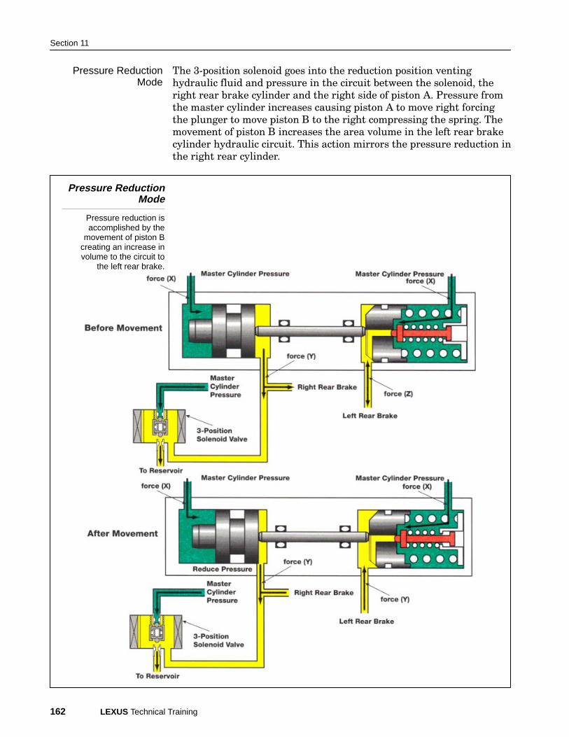
The 3−position solenoid goes into the reduction position venting
hydraulic fluid and pressure in the circuit between the solenoid, the
right rear brake cylinder and the right side of piston A. Pressure from
the master cylinder increases causing piston A to move right forcing
the plunger to move piston B to the right compressing the spring. The
movement of piston B increases the area volume in the left rear brake
cylinder hydraulic circuit. This action mirrors the pressure reduction in
the right rear cylinder.
Pressure ReductionMode
Pressure reduction isaccomplished by the
movement of piston Bcreating an increase involume to the circuit to
the left rear brake.
Pressure ReductionMode
Actuator Types
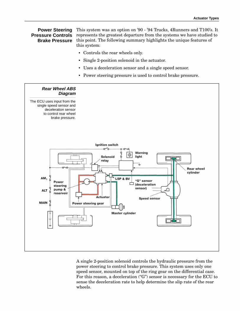
This system was an option on ’90 − ’94 Trucks, 4Runners and T100’s. It
represents the greatest departure from the systems we have studied to
this point. The following summary highlights the unique features of
this system:
• Controls the rear wheels only.
• Single 2−position solenoid in the actuator.
• Uses a deceleration sensor and a single speed sensor.
• Power steering pressure is used to control brake pressure.
Rear Wheel ABSDiagram
The ECU uses input from thesingle speed sensor and
deceleration sensorto control rear wheel
brake pressure.
A single 2−position solenoid controls the hydraulic pressure from the
power steering to control brake pressure. This system uses only one
speed sensor, mounted on top of the ring gear on the differential case.
For this reason, a deceleration (�G") sensor is necessary for the ECU to
sense the deceleration rate to help determine the slip rate of the rear
wheels.
Power SteeringPressure Controls
Brake Pressure
Section 11
164 LEXUS Technical Training
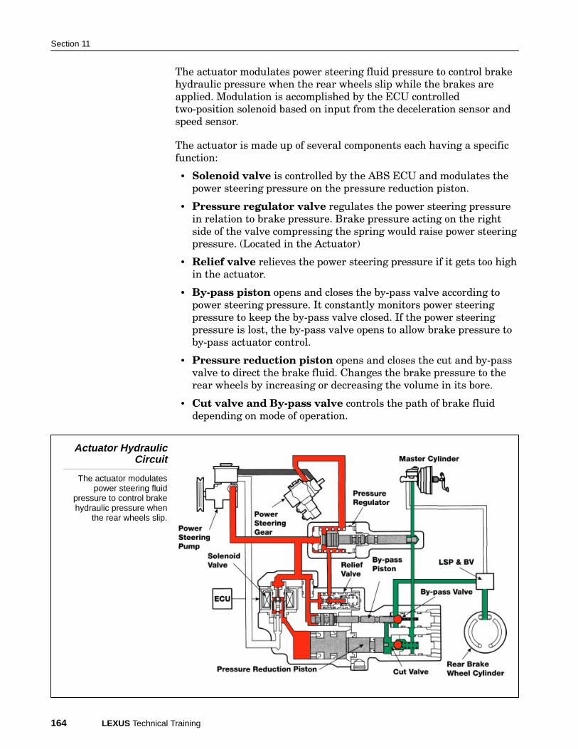
The actuator modulates power steering fluid pressure to control brake
hydraulic pressure when the rear wheels slip while the brakes are
applied. Modulation is accomplished by the ECU controlled
two−position solenoid based on input from the deceleration sensor and
speed sensor.
The actuator is made up of several components each having a specific
function:
• Solenoid valve is controlled by the ABS ECU and modulates the
power steering pressure on the pressure reduction piston.
• Pressure regulator valve regulates the power steering pressure
in relation to brake pressure. Brake pressure acting on the right
side of the valve compressing the spring would raise power steering
pressure. (Located in the Actuator)
• Relief valve relieves the power steering pressure if it gets too high
in the actuator.
• By−pass piston opens and closes the by−pass valve according to
power steering pressure. It constantly monitors power steering
pressure to keep the by−pass valve closed. If the power steering
pressure is lost, the by−pass valve opens to allow brake pressure to
by−pass actuator control.
• Pressure reduction piston opens and closes the cut and by−pass
valve to direct the brake fluid. Changes the brake pressure to the
rear wheels by increasing or decreasing the volume in its bore.
• Cut valve and By−pass valve controls the path of brake fluid
depending on mode of operation.
Actuator HydraulicCircuit
The actuator modulatespower steering fluid
pressure to control brakehydraulic pressure when
the rear wheels slip.

Actuator Types
Control of the brake fluid pressure acting on the rear brake cylinders is
carried out in three modes:
• pressure holding.
• pressure reduction.
• pressure increase.
The rear−wheel anti−lock brake system is not activated during normal
braking. In this mode the power steering fluid pressure acts on
chambers �C" and �D" pushing both the by−pass valve and cut valve
toward the right. This causes the cut valve to open and the normal port
on the left side of the by−pass valve to open.
When the brake pedal is depressed, the master cylinder fluid pressure
rises. The brake fluid passes from the cut valve to the normal port in
the by−pass valve, and is sent to the rear brake wheel cylinders.
Normal Braking
Power steering fluidpressure acts on chambers
“C” and “D” pushing boththe by-pass valve and cut
valve toward the right.
Operation DuringNormal Braking
Section 11
166 LEXUS Technical Training
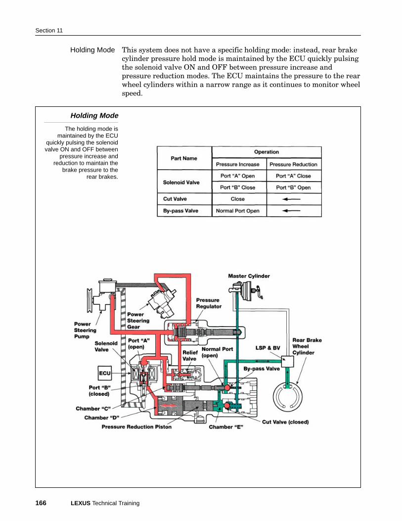
This system does not have a specific holding mode: instead, rear brake
cylinder pressure hold mode is maintained by the ECU quickly pulsing
the solenoid valve ON and OFF between pressure increase and
pressure reduction modes. The ECU maintains the pressure to the rear
wheel cylinders within a narrow range as it continues to monitor wheel
speed.
Holding Mode
The holding mode ismaintained by the ECU
quickly pulsing the solenoidvalve ON and OFF between
pressure increase andreduction to maintain the
brake pressure to therear brakes.
Holding Mode
Actuator Types
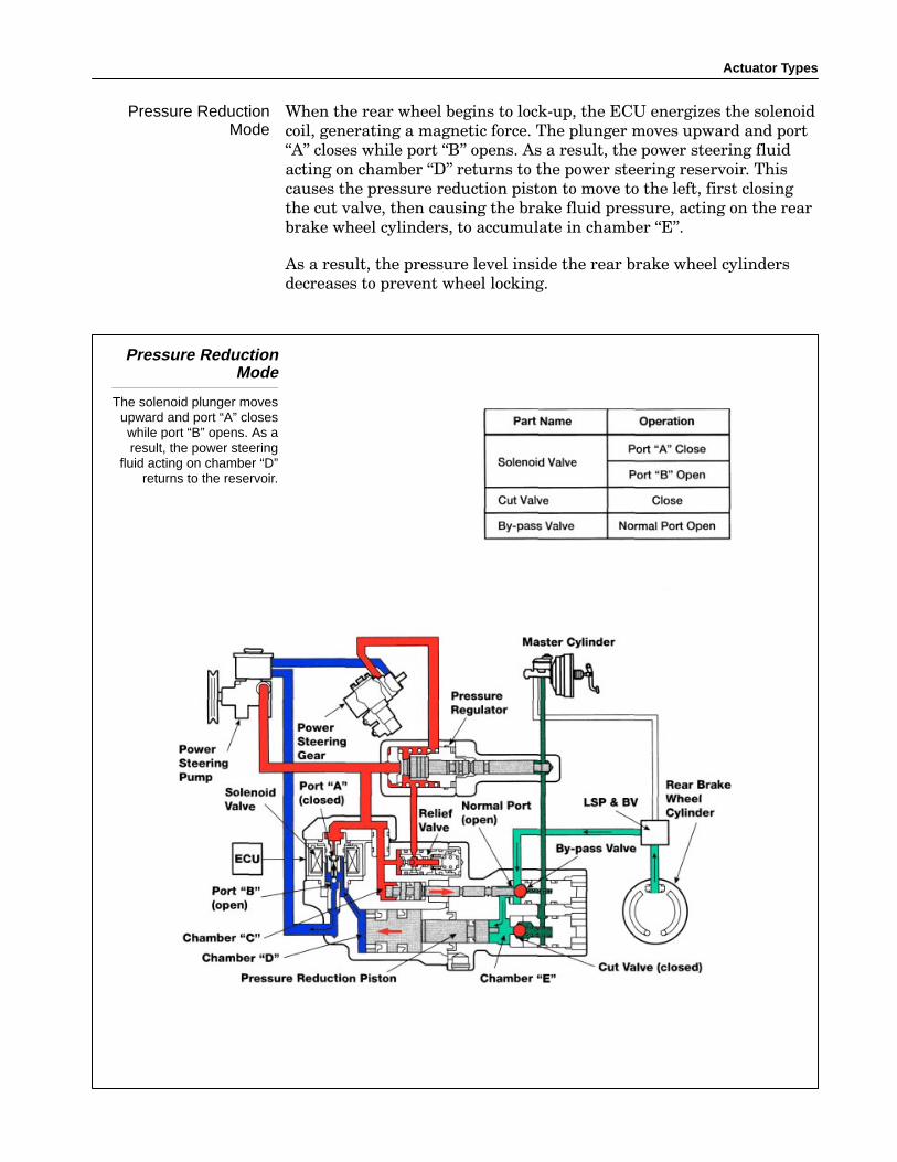
When the rear wheel begins to lock−up, the ECU energizes the solenoid
coil, generating a magnetic force. The plunger moves upward and port
�A" closes while port �B" opens. As a result, the power steering fluid
acting on chamber �D" returns to the power steering reservoir. This
causes the pressure reduction piston to move to the left, first closing
the cut valve, then causing the brake fluid pressure, acting on the rear
brake wheel cylinders, to accumulate in chamber �E".
As a result, the pressure level inside the rear brake wheel cylinders
decreases to prevent wheel locking.
Pressure ReductionMode
The solenoid plunger movesupward and port “A” closeswhile port “B” opens. As aresult, the power steering
fluid acting on chamber “D”returns to the reservoir.
Pressure ReductionMode
Section 11
168 LEXUS Technical Training
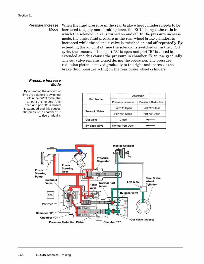
When the fluid pressure in the rear brake wheel cylinders needs to be
increased to apply more braking force, the ECU changes the ratio in
which the solenoid valve is turned on and off. In the pressure increase
mode, the brake fluid pressure in the rear wheel brake cylinders is
increased while the solenoid valve is switched on and off repeatedly. By
extending the amount of time the solenoid is switched off in the on/off
cycle, the amount of time port �A" is open and port �B" is closed is
extended and this causes the pressure in chamber �E" to rise gradually.
The cut valve remains closed during the operation. The pressure
reduction piston is moved gradually to the right and increases the
brake fluid pressure acting on the rear brake wheel cylinders.
Pressure IncreaseMode
By extending the amount oftime the solenoid is switched
off in the on/off cycle, theamount of time port “A” is
open and port “B” is closedis extended and this causesthe pressure in chamber “E”
to rise gradually.
Pressure IncreaseMode
Actuator Types
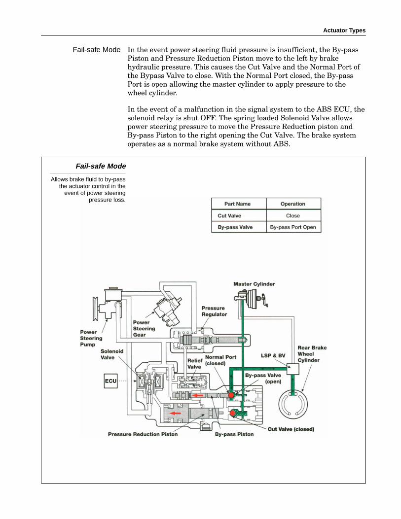
In the event power steering fluid pressure is insufficient, the By−pass
Piston and Pressure Reduction Piston move to the left by brake
hydraulic pressure. This causes the Cut Valve and the Normal Port of
the Bypass Valve to close. With the Normal Port closed, the By−pass
Port is open allowing the master cylinder to apply pressure to the
wheel cylinder.
In the event of a malfunction in the signal system to the ABS ECU, the
solenoid relay is shut OFF. The spring loaded Solenoid Valve allows
power steering pressure to move the Pressure Reduction piston and
By−pass Piston to the right opening the Cut Valve. The brake system
operates as a normal brake system without ABS.
Fail-safe Mode
Allows brake fluid to by-passthe actuator control in the
event of power steeringpressure loss.
Fail-safe Mode
Section 11
170 LEXUS Technical Training
Rear wheel ABS requires a special bleeding procedure when a
component of the steering system or the actuator is replaced. A typical
procedure is outlined here however, check the appropriate Repair
Manual as procedures may vary:
• Bleed the power steering system using the conventional method.
• Bleed the brake system with the engine running.
• Bleed the brake system with the engine OFF.
• Bleed the power steering system using the brake actuator checker.
The conventional method of bleeding the power steering system
requires that the reservoir be full.
• Run the engine at 1000 rpm or less.
• Turn the steering wheel from lock to lock three or four times.
• The fluid in the reservoir should not be foamy or cloudy indicating
presence of air.
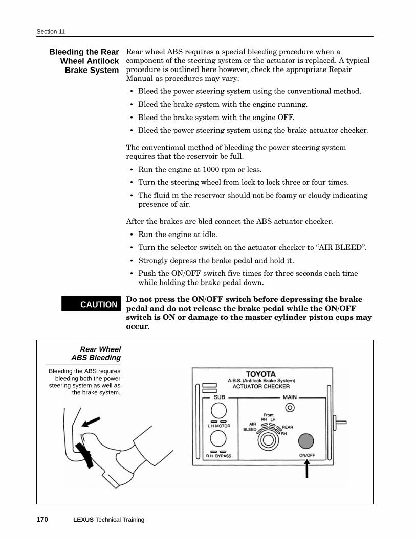
After the brakes are bled connect the ABS actuator checker.
• Run the engine at idle.
• Turn the selector switch on the actuator checker to �AIR BLEED".
• Strongly depress the brake pedal and hold it.
• Push the ON/OFF switch five times for three seconds each time
while holding the brake pedal down.
Do not press the ON/OFF switch before depressing the brake
pedal and do not release the brake pedal while the ON/OFF
switch is ON or damage to the master cylinder piston cups may
occur.
Rear WheelABS Bleeding
Bleeding the ABS requiresbleeding both the power
steering system as well asthe brake system.
Bleeding the RearWheel Antilock
Brake System
CAUTION

Actuator Types