section 1 - introductionmicrob/protocols/manuals/coulter_manual.pdf · section 2 installation.....8...
TRANSCRIPT

Multisizer 3 Operator’s Manual Table of Contents
PN 8321681 Rev. B i
TABLE OF CONTENTS
SECTION 1 INTRODUCTION ......................................................... 11.1 The Coulter Principle ........................................................................................................ 1
1.2 About the Multisizer 3 COULTER COUNTER............................................................. 2
1.3 About this Manual ............................................................................................................. 4
1.3.1 Conventions................................................................................................................... 4
1.3.2 Warnings and Cautions ................................................................................................. 5
1.4 Warnings........................................................................................................................... 5
1.4.1 Electrical ........................................................................................................................ 5
1.4.2 Chemical........................................................................................................................ 5
1.4.3 Mechanical..................................................................................................................... 5
1.4.4 Fire................................................................................................................................. 6
1.5 Cautions ............................................................................................................................ 6
1.5.1 Electrical ........................................................................................................................ 6
1.5.2 Chemical........................................................................................................................ 6
1.6 Warming up....................................................................................................................... 6
1.7 Sources of Error................................................................................................................ 6
1.7.1 Calibration constant ....................................................................................................... 6
1.7.2 Damaged apertures ....................................................................................................... 7
1.7.3 Deposits on and around aperture wafers ...................................................................... 7
1.7.4 External sound and mechanical vibration...................................................................... 7
1.7.5 Electrical interference .................................................................................................... 7
1.7.6 Particles behind the aperture......................................................................................... 7
1.7.7 Sample dispersion ......................................................................................................... 7
1.7.8 Excessive aperture current ............................................................................................ 7

Table of Contents Multisizer 3 Operator’s Manual
ii PN 8321681 Rev. B
SECTION 2 INSTALLATION.......................................................... 82.1 Location............................................................................................................................. 8
2.2 Unpacking ......................................................................................................................... 8
2.3 Connections ...................................................................................................................... 9
SECTION 3 BASIC OPERATIONS .............................................. 143.1 Starting the Instrument and its Control Program ............................................................ 14
3.2 Instrument Controls......................................................................................................... 15
3.3 Shutting down the Multisizer 3........................................................................................ 17
SECTION 4 GETTING STARTED ............................................... 184.1 Locating and Identifying Controls and Parts You Need to Know.................................... 18
4.1.1 The Front Panel of the Multisizer 3.............................................................................. 18
4.1.2 The Sample Compartment .......................................................................................... 18
4.2 Fitting the Electrode and Stirrer ...................................................................................... 20
4.3 Fitting the Aperture Tube ................................................................................................ 21
4.4 Setting Up the Aperture Tube ......................................................................................... 22
1. Removing the currently installed aperture tube. ............................................................. 23
2. Installing a New Aperture Tube...................................................................................... 24
3. Placing a beaker of clean electrolyte on the platform..................................................... 25
4. Closing the Sample Compartment door......................................................................... 25
5. Selecting the electrolyte.................................................................................................. 26
6. Selecting the aperture tube............................................................................................. 26
7. Filling the System............................................................................................................ 27
8. Adjusting the Metering Pump.......................................................................................... 27
9. Setting Current and Gain. ............................................................................................... 28
10. Measuring Noise Level. ............................................................................................... 29
11. Calibration and Verfication of the Calibration .............................................................. 29
4.5 Aligning the Optics .......................................................................................................... 30

Multisizer 3 Operator’s Manual Table of Contents
PN 8321681 Rev. B iii
SECTION 5 CALIBRATION AND VERIFICATION OFCALIBRATION.......................................................... 31
5.1 Choosing the Calibrator .................................................................................................. 31
5.2 Preparing the Calibrator.................................................................................................. 31
5.3 Running the Calibrator .................................................................................................... 33
5.4 Obtaining the mean Kd .................................................................................................. 35
5.5 Entering the mean value for the Kd in the aperture list .................................................. 35
5.6 Verifying the calibration................................................................................................... 37
SECTION 6 SAMPLE ANALYSIS ................................................ 406.1 Introduction ..................................................................................................................... 40
6.2 Changing Standard Operating Method (SOM). .............................................................. 41
6.3 Convert Pulses to Size Settings...................................................................................... 49
6.4 Saving Standard Operating Method................................................................................ 50
6.5 Entering Sample Information .......................................................................................... 51
6.6 Running a Background. .................................................................................................. 55
6.7 Subtracting the Background............................................................................................ 56
6.8 Running the Sample ....................................................................................................... 57
6.10 Cleaning the System....................................................................................................... 58
SECTION 7 REVIEWING AND SAVING THE RESULTS............... 607.1 Introduction ..................................................................................................................... 60
7.2 Opening a File................................................................................................................. 60
7.3 Overlaying Files .............................................................................................................. 63
7.4 Averaging Files ............................................................................................................... 67
7.5 Creating a Size Trend ..................................................................................................... 72
7.6 Overlapping Files from Different Aperture Sizes. ........................................................... 76
SECTION 8 PRINTING A REPORT .............................................. 808.1 Introduction ..................................................................................................................... 80

Table of Contents Multisizer 3 Operator’s Manual
iv PN 8321681 Rev. B
8.2 Selecting the Content of the Printed Report ................................................................... 80
8.2.1 Sample Info.................................................................................................................. 81
8.2.2 Size Section of the Printed Report .............................................................................. 82
8.2.3 Size Statistic Section of the Printed Report................................................................. 87
8.2.4 Pulses Section of the Printed Report........................................................................... 89
8.2.5 Trend Section of the Printed Report ............................................................................ 91
8.2.6 Printer Section ............................................................................................................. 93
8.2.7 Closing the Printing Report Dialog Box ....................................................................... 93
8.3 Customizing the Preferences.......................................................................................... 94
8.3.1 Size .............................................................................................................................. 94
8.3.2 Trend ......................................................................................................................... 101
8.3.3 Pulses ........................................................................................................................ 102
8.3.4 Other Options for the Preference File....................................................................... 103
8.3.5 Averaging and Trend ................................................................................................. 104
8.3.6 Number and Date Formats ........................................................................................ 105
8.3.7 Data Export ................................................................................................................ 106
8.3.8 Graph Options ........................................................................................................... 106
8.3.9 Page Setup ................................................................................................................ 107
8.3.10 Pick Fonts .................................................................................................................. 107
8.3.11 Windows Colors......................................................................................................... 108
8.3.12 Customize Toolbar..................................................................................................... 108
8.3.13 Selecting the Language............................................................................................. 109
8.3.14 Saving Preferences ................................................................................................... 109
SECTION 9 CREATING A STANDARD OPERATINGPROCEDURE (SOP)............................................... 111
9.1 Introduction ................................................................................................................... 111
9.2 Creating and Saving an SOP........................................................................................ 111
9.2.1 Selecting the SOM file. .............................................................................................. 112

Multisizer 3 Operator’s Manual Table of Contents
PN 8321681 Rev. B v
9.2.2 Selecting the Preferences File................................................................................... 114
9.2.3 Saving the SOP ......................................................................................................... 115
9.3 Using An SOP............................................................................................................... 116
9.4 Removing Active SOP .................................................................................................. 117
SECTION 10 REGULATORY COMPLIANCE ............................. 11810.1 21 CFR Part 11 ............................................................................................................. 118
10.2 Electronic records ......................................................................................................... 118
10.3 FDA Requirements ....................................................................................................... 118
10.4 Implementation of electronic records and electronic signatures................................... 118
10.5 Controls for electronic records...................................................................................... 119
10.6 Establishing an electronic record control with the Multisizer™ 3.................................. 119
10.6.1 Setting up security ..................................................................................................... 119
10.6.2 Adding a user account ............................................................................................... 120
10.6.3 Selecting user names and passwords....................................................................... 121
10.6.4 File History and Audit Trail......................................................................................... 122
10.6.5 Setting Audit Trail ...................................................................................................... 124
10.6.6 Selecting user privileges............................................................................................ 125
10.6.7 Electronic Signature................................................................................................... 126
10.6.8 Generating electronic signatures............................................................................... 126
10.6.9 Applying electronic signatures................................................................................... 127
10.6.10 Additional security features .................................................................................... 128
10.7 Starting the Multisizer 3 software with enabled security. .............................................. 128
SECTION 11 SPECIFICATIONS.................................................. 12911.1 Dimensions and weight................................................................................................. 129
11.2 Environmental Conditions ............................................................................................. 129
11.3 Operational Parameters................................................................................................ 129
11.4 Regulatory Compliance................................................................................................. 126


Multisizer 3 Operator’s Manual Section 1
PN 8321681 Rev. B 1
SECTION 1 INTRODUCTION1.1 The Coulter Principle
In the late 1940’s a technique that allowed particles homogeneously suspended in aconducting liquid to be simultaneously counted and sized was developed and patentedby Wallace Coulter. Instruments employing this technique were originally designed tofacilitate blood cell analyses but over the years have become invaluable tools in industrialapplications as well. The Coulter Principle, also known as the Electrical Sensing Zone (orESZ) method, is referenced in many national and international standards, and analysesas well as analytical instruments based on the Coulter Principle often serve as referencesin the evaluation of both other particle size analyzers and sizing techniques.
In the ESZ method a suspension is made to flow through a small cylindrical opening (theaperture) separating two electrodes between which an electric current flows. Althoughthe magnitude of this current may be small, (typically about 1 mA), the resistance, or“pinch”, created by the restriction separating the electrodes produces a considerablecurrent density within the aperture. As each particle passes through the aperture (or“sensing zone”) it displaces its own volume of conducting liquid, momentarily increasingthe impedance of the aperture.
Figure 1.1-1 Diagrammatic illustration of the Coulter Principle applied in the Multisizer 3
This change in impedance produces a tiny but proportional current flow into an amplifierthat converts the current fluctuation into a voltage pulse large enough to measureaccurately. The Coulter Principle states that the amplitude of this pulse is directlyproportional to the volume of the particle that produced it. Scaling these pulse heights in

Section 1 Multisizer 3 Operator’s Manual
2 PN 8321681 Rev. B
volume units enables a size spectrum to be acquired and displayed. In addition, if ametering apparatus is used to draw a known volume of the suspension through theaperture, a count of the number of pulses will yield the concentration of particles per unitvolume in the suspension.
In industrial applications historically it has been common practice to report particle ‘size’in linear terms, and so the volume of a particle is converted into an equivalent sphericaldiameter (ESD). In this case, the “particle size” is the diameter of a sphere whosevolume is equal to that of the particle. The biological and biomedical sciencestraditionally (when reporting the results of cellular analyses) are more accustomed tousing actual volumetric metric units, and in these applications “particle size” is usuallypresented in terms such as femtoliters or cubic microns (fL, or µL3).
Particle surface areas can be calculated, with the assumption that the surface area isthat derived from (and equates to) the surface area of a perfect sphere whose ESD isthe same as that of the volume of the particle.
The International Standard ISO 13319 Determination of Particle Size Distributions-Electrical Sensing Zone Methods describes and gives guidance on the measurement ofthe size distribution of particles using the Coulter Principle.
1.2 About the Multisizer 3 COULTER COUNTER
The BECKMAN COULTER Multisizer 3 is a flexible, multi-channel analyzer employingthe Coulter Principle (or Coulter electrical impedance method) together with state-of-the-art Digital Pulse Processing (DPP) technology to provide both particle sizing andcounting within an overall size range of 0.4 µm to 1200 µm. Data is acquired andprocessed using proprietary DSP circuitry and may be archived, displayed and re-analyzed on any PC equipped with a Pentium® II or similar microprocessor runningBeckman Coulter’s Multisizer™3 software on Microsoft’s Windows® operating systemsversions 95, 98, 2000 or NT 4.0.
The Multisizer 3 uses a unique, mercury-free system to draw suspensions through theaperture at a steady rate and to meter these liquid volumes precisely enough to yieldaccurate particle concentration measurements. The instrument is also equipped with acontinuous flow alternative for applications where accuracy of liquid metering isunimportant or less critical, as well as options that allow the user to define analysisparameters based on elapsed time or particle count.
By using the very latest in digital pulse measurement techniques, an entire analysis(which may consist of many thousands of particle pulses) can be stored either inmemory, or on disk, for recall and reprocessing. This technology allows, for the firsttime, the resolution of an analysis to be increased up to a hundred-fold by narrowing thesize range of interest in real time, eliminating the need to re-run the sample. Using the"Convert Pulses to Size” feature in the software, measurements from the lowest to thehighest possible resolution can be made on just one pass of sample through theaperture.
Storing the individual values of pulse heights means that it is not necessary topredetermine the number of size classes (also called “channels” or "size bins") intowhich any size distribution can be divided. This choice is at the discretion of theoperator and can be chosen either before or after the analysis or even changed duringanalysis. Any number of channels from 4 up to 300 may represent a partial or full rangeof an aperture. A smaller number may improve the appearance of a size distribution byreducing statistical scatter in the results, while details in the results may be enhanced by

Multisizer 3 Operator’s Manual Section 1
PN 8321681 Rev. B 3
increasing the number of size classes in regions of particular interest. A higher numberof channels provides more detail about the size of the particles The advanced digitalelectronics used in the Multisizer 3 allow the number of channels to be changed in realtime without losing any of the information acquired with other channel spacing.
Results can also be stored in a fully processed (abridged) form that conserves diskspace. Although in this form the raw pulse data is lost and so cannot be re-analyzed at adifferent resolution, the processed results still can be enlarged, or a region of interestselected, using the "Zoom” facility in the software.
Both number data and size distributions are corrected by proprietary algorithms for theoccurrence of multiple particle passage (coincidence) in the aperture. An indicatorprovides real time particle concentration in the analysis suspension. The Multisizer 3software includes a pulse monitor window that offers a guide to the electronic behavior ofthe aperture. The time base of this window can be adjusted to show either pulseconcentration or the shapes of individual pulses. Electronic pulse editing facilities ensurethat very narrow size distributions can be highly resolved by minimizing the effect of linewidth broadening in the sensing aperture.
Data can be displayed graphically as number, volume, mass and surface area sizedistribution plots, or as tables of values versus size. Both display types can show data asdifferential or cumulative frequencies. Full data reduction facilities are included forstatistical and trend analysis, with export and import capabilities to text and spreadsheetprograms via disk files or the Windows Clipboard. All results can be printed/plotted onany printer that has an installed driver compatible with the PC’s Windows platform.
A report facility allows results to be combined with sample information in a userselectable way to produce a systematic reporting configuration. Report formats can beindividually named for ease of archiving and retrieval. Number and date formats aresupported in both conventional as well as in ISO 9276-1 forms.
The Multisizer 3 system, illustrated in figure 1.2-1, comprises an integrated fluid handlingand pulse processing unit (the Analyzer Module), and a personal computer with an XVGAmonitor. (A keyboard, mouse and an ink-jet printer are also part of the system but arenot shown in the figure.)
Figure 1.2-1 The Multisizer 3 system
Section 1 Multisizer 3 Operator’s Manual
4 PN 8321681 Rev. B
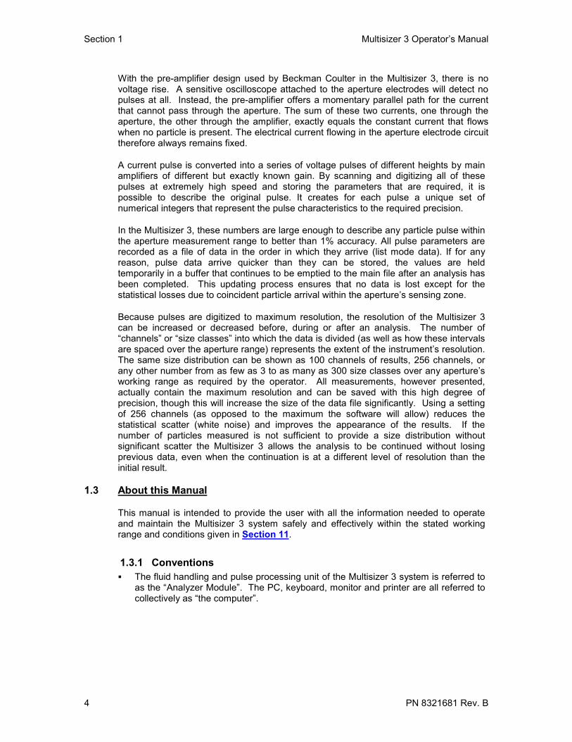
With the pre-amplifier design used by Beckman Coulter in the Multisizer 3, there is novoltage rise. A sensitive oscilloscope attached to the aperture electrodes will detect nopulses at all. Instead, the pre-amplifier offers a momentary parallel path for the currentthat cannot pass through the aperture. The sum of these two currents, one through theaperture, the other through the amplifier, exactly equals the constant current that flowswhen no particle is present. The electrical current flowing in the aperture electrode circuittherefore always remains fixed.
A current pulse is converted into a series of voltage pulses of different heights by mainamplifiers of different but exactly known gain. By scanning and digitizing all of thesepulses at extremely high speed and storing the parameters that are required, it ispossible to describe the original pulse. It creates for each pulse a unique set ofnumerical integers that represent the pulse characteristics to the required precision.
In the Multisizer 3, these numbers are large enough to describe any particle pulse withinthe aperture measurement range to better than 1% accuracy. All pulse parameters arerecorded as a file of data in the order in which they arrive (list mode data). If for anyreason, pulse data arrive quicker than they can be stored, the values are heldtemporarily in a buffer that continues to be emptied to the main file after an analysis hasbeen completed. This updating process ensures that no data is lost except for thestatistical losses due to coincident particle arrival within the aperture’s sensing zone.
Because pulses are digitized to maximum resolution, the resolution of the Multisizer 3can be increased or decreased before, during or after an analysis. The number of“channels” or “size classes” into which the data is divided (as well as how these intervalsare spaced over the aperture range) represents the extent of the instrument’s resolution.The same size distribution can be shown as 100 channels of results, 256 channels, orany other number from as few as 3 to as many as 300 size classes over any aperture’sworking range as required by the operator. All measurements, however presented,actually contain the maximum resolution and can be saved with this high degree ofprecision, though this will increase the size of the data file significantly. Using a settingof 256 channels (as opposed to the maximum the software will allow) reduces thestatistical scatter (white noise) and improves the appearance of the results. If thenumber of particles measured is not sufficient to provide a size distribution withoutsignificant scatter the Multisizer 3 allows the analysis to be continued without losingprevious data, even when the continuation is at a different level of resolution than theinitial result.
1.3 About this Manual
This manual is intended to provide the user with all the information needed to operateand maintain the Multisizer 3 system safely and effectively within the stated workingrange and conditions given in Section 11.
1.3.1 Conventions The fluid handling and pulse processing unit of the Multisizer 3 system is referred to
as the “Analyzer Module”. The PC, keyboard, monitor and printer are all referred tocollectively as “the computer”.

Multisizer 3 Operator’s Manual Section 1
PN 8321681 Rev. B 5
means “click the mouse button”. Unless the mouse has been inverted for left-handed users, this will be the left mouse button.
means “double click the (left) mouse button”.
⌧⌧⌧⌧, and mean “check the box or radio button”, and � and ๐ mean “uncheck thebox or button” or leave unchecked.
1.3.2 Warnings and Cautions
Indicates a situation or condition that might result in personal injuryif not corrected.
Indicates a situation or condition that, if ignored or proceeded with,may result in damage to the instrument or serious error in the resultsproduced by it.
(Help note) contains hints and useful information to help optimizeresults quality and ease of use.
1.4 Warnings
1.4.1 Electrical(1) High voltages are present inside the instrument. Always disconnect the
instrument from the power supply before removing the cover.
(2) The instrument must be grounded correctly.
1.4.2 Chemical(1) Do not use any electrolyte solutions or diluents that are not compatible with the
materials of construction. Consult Beckman Coulter Inc. or its localrepresentative before using any concentrated acids or alkalis in the instrument.
(2) Toxicity, safety, and proper handling procedures for diluents and reagents usedin particle and cell analysis should be adhered to at all times. Consultappropriate safety manuals and Material Safety Data Sheets for the items.
(3) Care should be taken when mixing or exchanging diluents. Reactions can occurbetween incompatible solvents and electrolyte salts, and may be violent.
(4) Do not use azide and cyanide salts in acid solutions.
(5) Flammable electrolyte solutions should be prepared for use in an appropriateenvironment and brought to the instrument only when required for an analysis.
1.4.3 Mechanical(1) Do not interfere with or attempt to disable the interlocks incorporated in the door
and beaker platform assembly.
(2) Do not use force to remove or replace any glass item. In the event of difficulty,consult Beckman Coulter Inc. or its local representative.
(3) Replace an aperture tube empty of diluent. Do not attempt to pre-fill a tubebefore locating it in the aperture tube connector.

Section 1 Multisizer 3 Operator’s Manual
6 PN 8321681 Rev. B
1.4.4 Fire(1) Many non-aqueous electrolyte solutions are flammable and contain organic salts
that can support or enhance fire. Where possible choose less flammablealternatives.
(2) Prepare and filter flammable solvents and diluents away from the Multisizer 3itself, preferably under a suitable fume hood. Extinguish all open flames in thevicinity and observe normal precautions against ignition by hot surfaces orelectrical sparks.
1.5 Cautions
1.5.1 Electrical(1) Use the Windows® Shut Down command to turn the computer off before
switching off power. Switching off power first will generate a Windows errormessage at next computer start up.
(2) Power must be largely free from interference. The Multisizer 3 is CE, UL andCSA compliant with regards to electrical interference but some circumstancesmay benefit from a constant voltage transformer or regulator.
1.5.2 Chemical(1) If Beckman Coulter ISOTON® II diluent is used, the Multisizer 3 must be drained
and flushed through with distilled water before carrying out a bleach disinfectionprocedure.
(2) If the Multisizer 3 has been subjected to a bleach (sodium hypochlorite solution)disinfection procedure, the instrument must be drained and flushed through withdistilled water before refilling with ISOTON® II.
(3) Take care disconnecting diluent lines -- open-ended tubing may allow liquid tosiphon out of containers.
(4) Never stand containers of liquids on top of the Multisizer 3. Repair ofinstruments damaged or affected by spilt liquids will not be covered by anywarranty or guarantee.
1.6 Warming upAs with all sensitive electronic instruments, the Multisizer 3 components offer bestperformance once they have reached a steady working temperature. This may typicallytake 15 minutes from power on.
1.7 Sources of Error
1.7.1 Calibration constant
Size distributions are only correct if the calibration constant (Kd) used toconstruct the size scale is correct. Instructions on how to calibrate an apertureare contained in Section 5. If a different constant is entered manually, thesoftware will use the manually entered value despite the fact that this may resultin an incorrect calculation of the size range appropriate for that particularaperture.
Multisizer 3 Operator’s Manual Section 1
PN 8321681 Rev. B 7
1.7.2 Damaged apertures
Aperture damage, such as a cracked wafer, can exhibit a variety of symptoms.Usually, it results in sporadic bursts of high counts at the lower aperture sizelimit. It is often the cause of deterioration in blank count in a tube previouslygiving quiet and reliable blank counts.
1.7.3 Deposits on and around aperture wafers
Protein and others biological materials may create a deposit on apertures thatcould alter their calibration and background count characteristics. Aperturesused for these applications should be subjected to appropriate cleaningprocedures at frequent intervals. It is advisable to perform a cleaning procedureto avoid any material deposit or microbial growth inside the system (see Section6.10).
1.7.4 External sound and mechanical vibration
Loud sounds and vibrations may register in the aperture as measurable pulses.
1.7.5 Electrical interference
Electrical interference both from the power line and radiated may, if outside thescope of EMC compliance requirements, produce erroneous measurements.
1.7.6 Particles behind the aperture
In the case of either very large or unusually dense materials, particles may settleinside the aperture tube when the instrument is standing idle. Sediments ofsuch particles have been known to swirl up behind the aperture when theinstrument is then used and cause interference with subsequent counts and sizedistributions.
1.7.7 Sample dispersion
Measurements of powder dispersions are only as good as the dispersed state ofthe sample and the sampling procedure allows. Incorrectly dispersed or unstabledispersions will give rise to incorrect results.
1.7.8 Excessive aperture currentExcessive current causes the electrolyte solution in the aperture to heat, or evento boil, causing noise (see Section 4.4.9).
Back to TOC

Section 2 Multisizer 3 Operator’s Manual
8 PN 8321681 Rev. B
SECTION 2 INSTALLATION2.1 Location
Ideally the instrument should be located in a dust free room. Dusty environments shouldbe avoided to minimize sample contamination. The instrument should be placed on abench that is not subject to:
(1) Excessive airborne dust
(2) Strong vibrations
(3) Spillage or splashing
(4) Sounds of high intensity (e.g., ball mills, ultrasonic baths or probes); electrical noise(e.g., electrical switching gear, water baths or gas chromatographs)
2.2 Unpacking
The Multisizer 3 will normally be installed only by Beckman Coulter approved andtrained installation engineers. Unless otherwise agreed to by Beckman Coulter, DONOT UNPACK the Multisizer 3.
The Multisizer 3 is a heavy instrument. Follow the instructions below. Failureto do so may result in personal injury and/or damage to the instrument. Suchdamage may not be covered by warranty.
Figure 2.2-1 Unpacking the Multisizer 3 Analyzer Module
(1) Lift the Analyzer Module (requires two people) off the pallet and onto the bench takingcare not to exert any force on or lift by the plastic front compartment molding (see Figure2.2-1).
(2) Turn the outer box over to gain access to the Accessories and Installation Pack fastenedto the inside top of the outer box. Slide out the Pack and inspect all installation items fordamage. Compare the contents with the Packing List.

Multisizer 3 Operator’s Manual Section 2
PN 8321681 Rev. B 9
(3) Report any missing items or damage to any part of the instrument to Beckman Coulteror their local distributor, and to the carrier responsible for delivery. Do not send backany items before receiving instructions to do so from the manufacturer.
Figure 2.2-2 Unpacking the computer monitor
(4) Open the carton containing the computer monitor and remove the monitor as shown infigure 2.2-2 by inverting the carton and slitting the tape along the box bottom flaps. Turnthe carton back upright and slide it upward from the monitor.
(5) Unpack the computer and printer by placing upright on the bench and slitting the tapearound all box flaps. Lift the items out from the boxes. Compare the computer andprinter manufacturers’ packing lists and report any deficiencies or damage as in (3)above.
2.3 Connections
1. Remove the tubing and containers kit from its package.
2. Prepare the lids for each container. The waste lid uses one curve tube to connect thecontainer to the waste outlet of the instrument and has only one connection cable. Theelectrolyte lid uses two tubes and it has a connector cable and ground cable. Thestraight tube, the intake tube, goes from the inner side of the lid to the bottom of theelectrolyte container. The curve tube connects the container to the electrolyte intake onthe side of the instrument (See Figure 2.3.1 and 2.3.2).
3. Leave the waste container empty and screw the lid with the sensor and tube. Fill theelectrolyte container with the required electrolyte and screw the lid down.
4. Attach the appropriate tube from each container to the fittings marked "Diluentl"(Electrolyte) and "Waste" at the top of the left side panel (See Figure 2.3.2).

Section 2 Multisizer 3 Operator’s Manual
10 PN 8321681 Rev. B
Figure 2.3.1 Assembly of theElectrolyte/WasteSystem
ElectrolyteWaste
1 1
2 234
5
6
78
1. Containers2. Lids3. Connecting Tubes4. Electrolyte Intake Tubing5. Connecting Cables6. Ground Cable7. Electrolyte Sensor8. Waste Sensor

Multisizer 3 Operator’s Manual Section 2
PN 8321681 Rev. B 11
Electrolyte andWaste SensorsConnectors
Ground
Figure 2.3-2 Left side panel showing waste and diluent connections
5. Plug the connector cables from the Waste and Diluent sensors into the dual socketsimmediately behind the pipe fittings on the left-hand side of the instrument. Either cable maygo into either socket. Plug the ground cable from the electrolyte sensor into the groundsocket (See Figure 2.3.2).
The Multisizer 3 can only check the level in the waste container supplied. Ifthe waste tube is taken directly to a drain, take care that it drains freely andthat flow does not back up or become obstructed. Follow local regulationswhen disposing of harmful waste. Permission may be required from wastedisposal authorities for drainage into waste water systems.
6. Use the EtherNet cable supplied with the instrument to connect the Multisizer 3 to the PC’snetwork card. (See Figure 2.3.3). The parallel and serial connectors are intended to be usedby Beckman Coulter authorized service personnel.
7. Check that the voltage selection indicator located on the rear side of the instrument is set forthe voltage (line voltage) to which the instrument is to be connected. (see Figure 2.3-4).
All items comprising the Multisizer 3 system must be set for the correctvoltage. Connecting the instrument to an incorrect voltage may causedamage to the instrument and invalidate any warranty. Different voltagesrequire appropriate fuses.
8. If the selector does not indicate the correct voltage setting, change it as follows: Remove thefuse holder and cover plate by inserting a small bladed screwdriver (~3 mm blade width) intothe recess at the top (figure 2.3-4). Lever upwards to “pop out” the holder. Using needlenosed pliers, pull out the voltage selector board. Do not pull on the plastic voltage indicatorpin. Voltage values are marked around the four corners of the plate (Figure 2.3-4). Holdingthe board as shown in Figure 2.3-4B, pull out the plastic pin as far as it will go (Figure 2.3-4C) and rotate it so that it points outwards towards the cover plate. Figure 2.3-4D shows theorientation of the pin for 120 V.
(a) Push the pin back in towards the board (the pin will locate in a recess unique tothe chosen voltage). Turn the board until the voltage required faces inwards(towards the instrument). Replace the selector board and push firmly into place.
(b) If fuses need replacing use only 250 V, 3.15 A, “T” (time delay), IEC standard 20mm fuses.

Section 2 Multisizer 3 Operator’s Manual
12 PN 8321681 Rev. B
(c) Fit the cover plate so that the appropriate small hole at its base fits over the whiteplastic indicator pin and push firmly at the top until it clicks into its seating. Thewhite pin should now indicate the correct voltage for the supply. The positions leftto right are: (See Figure 2.3-3).
9. Make sure all the power switches of the Multisizer 3, the computer, and the printer are set toO (=OFF) then connect these items to power with the cables supplied.
10. First switch the Multisizer 3 analyzer unit power switch to (=ON), followed by the computerand printer. To find out how to use the instrument’s control program turn to Section 3.3.1
Figure 2.3-3 Detail from the bottom left side of the rear panel showing the connections to thePC and the power socket with the fuse holder

Multisizer 3 Operator’s Manual Section 2
PN 8321681 Rev. B 13
Figure 2.3-4 The voltage selector board: B shows the orientation for 240 V; C & D show
the conversion from 240 V to 120 V, and E the final orientation for 120 V
before re-insertion. Back to TOC

Section 3 Multisizer 3 Operator’s Manual
14 PN 8321681 Rev. B
SECTION 3 BASIC OPERATIONSThe software controls all the operations on the Multisizer 3. Only the stirrer speed andthe sample platform need to be adjusted manually on the analyzer unit.
3.1 Starting the Instrument and its Control Program1. If the analytical system has been started before the program has been launched, the
first view presented by the program is the copyright acknowledgement box (Figure3.1-1). If the checkbox is unchecked, the program will behave purely as a dataprocessing program and the Multisizer 3 control menu options will be either “greyedout” or not displayed.
Figure 3.1-1 Copyright Acknowledgement Box
2. Check the box Connect to Multisizer 3, OK to launch the control program.
If the analyzer unit has not already been switched on, do not check the“Connect to Multisizer 3” box. Connection can be made later under“Run” in the Main Menu Bar.
3. Once connection has been made, a series of status messages illustrate theinitializing process of the Analyzer Module. These normally start with “Waiting”and/or “Initializing valves” but the precise sequence will depend on the actual startcondition of the Analytical Module. After initializing the complete system, the statusmessage will change to “Ready” (see Figure 3.1-2).
4. The Security Set Up dialog box is shown the first time that the program is started. Atthis moment the security level can be selected. These security options can also beselected at a later time (see Section 10.7.1). It is advisable to read Section 10before selecting the security level.
5. To set up the security options at a later time, Cancel in the Security Set Updialog box (see Figure 3.1-3). Refer to Section 10 to set up security at a later time.
6. To select the security level at this time choose the required level option (see Figure3.1-3). OK and go to Section 10.
Multisizer 3 Operator’s Manual Section 3
PN 8321681 Rev. B 15
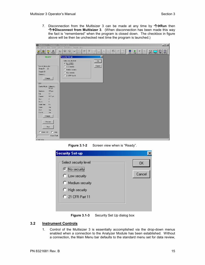
7. Disconnection from the Multisizer 3 can be made at any time by Run thenDisconnect from Multisizer 3. (When disconnection has been made this way
the fact is “remembered” when the program is closed down. The checkbox in figureabove will be then be unchecked next time the program is launched.)
Figure 3.1-2 Screen view when is “Ready”.
Figure 3.1-3 Security Set Up dialog box
3.2 Instrument Controls1. Control of the Multisizer 3 is essentially accomplished via the drop-down menus
enabled when a connection to the Analyzer Module has been established. Withouta connection, the Main Menu bar defaults to the standard menu set for data review,

Section 3 Multisizer 3 Operator’s Manual
16 PN 8321681 Rev. B
editing, and printing. In this case the control menus are no longer visible. (TheMultisizer 3 software, because of the digitization of pulse data, has the ability to re-process previously acquired results, as long as the data was stored with the optionto include the pulse data selected.)
Figure 3.2-1 The Status Panel
2. Provided connection to the Analyzer Module has already been established,stopping and starting an analysis is controlled by “Buttons” on the Status Panelshown on the left side of the Control Page. These buttons change their functionand annotation according to the status of the analysis.
3. The instrument can also be directly controlled via the drop-down menus, forexample:

Multisizer 3 Operator’s Manual Section 3
PN 8321681 Rev. B 17
Run Start has exactly the same function as the Start button on the control panel.Likewise, other analysis controls are available via Run Menu.
Figure F3.2-2 The Run Menu
3.3 Shutting down the Multisizer 3At any time, the software program can be closed down by any of the standardWindows applications closing actions such as:
File on the Main Menu Bar then Close,
or ⌧⌧⌧⌧ on the Window top right-hand corner.
(1) When the program has been closed, the Analyzer Module power switch can beswitched off.
(2) Closing down the program leaves the Multisizer 3 connection in its last state. Ifconnection has been enabled, the copyright acknowledgement box will show“Connect to Multisizer 3” checked next time the program is started. If theconnection has already been disabled through “Run”, the copyrightacknowledgement box will show the “Connect to Multisizer 3” box unchecked.
(3) If the Analyzer Module is switched off before the program has been closed,connection to the PC is automatically broken, and may be recorded as adisconnection. It will then be necessary to re-enable the connection by
Run Connect to Multisizer 3.
Back to TOC

Section 4 Multisizer 3 Operator’s Manual
18 PN 8321681 Rev. B
SECTION 4 GETTING STARTED4.1 Locating and Identifying Controls and Parts You Need to Know
4.1.1 The Frontal Panel of the Multisizer 3
Stirrer RotationControl
Stirrer Speed Control
Aperture Viewer
Sample CompartmentGlass Door
Handle to Open theSample Compartment
Figure 4.1-1 Front view of the instrument.
On the front panel of the instrument you will find:• Aperture Viewer: This screen allows visual monitoring of the aperture.• Stirrer Rotation Control: This knob changes the direction the stirrer rotates.• Stirrer Speed Control: This knob is used to set the rotation speed of the stirrer and
to turn it on and off. The stirrer can also be turned on or off from the Multisizer 3software.
4.1.2 The Sample CompartmentThe sample compartment is enclosed in a Faraday Cage to avoid electric interference.Opening the glass door of the sample compartment you can find the Sample Platformand the places where the electrode and stirrer have to be attached (See Figures 4.1.2and 4.1-3).Inside the Sample Compartment you will find:
• Electrode• Stirrer• Aperture Tube• Sample Platform

Multisizer 3 Operator’s Manual Section 4
PN 8321681 Rev. B 19
• Trap: Its function is to prevent large and dense particles to go into the system. When thesample sediment reaches the red mark it is necessary to clean the trap.
• Aperture Tube Knob: This knob is used to hold or release the Aperture Tube.
• Stirrer Knob: This knob is used to fix the position of the stirrer.
SamplePlatform
Trap
ApertureTube Stirrer
Electrode
Figure 4.1-2 The sample compartment
StirrerKnob
Stirrer
Trap
Aperture TubeKnob
ApertureTube
Beaker
Figure 4.1-3 Inside the sample compartment

Section 4 Multisizer 3 Operator’s Manual
20 PN 8321681 Rev. B
4.2 Fitting the Electrode and Stirrer1. Carefully remove the electrode and stirrer from their packages.
2. Hold the electrode only by its metal connector and insert it into the electrode socketlocated on the upper side of the sample compartment. Rotate it until the platinumspade is positioned roughly parallel with the lamp lens axis behind the aperturetube then push up to complete the connection. (See Figure 4.2-1).
Electrode
Figure 4.2-1 Electrode.
The electrode stem is made of glass and is therefore fragile. If the connectordoes not enter its socket easily, do no use undue force. Do not twist, pushor pull the glass stem in any way. Hold the electrode only by the connector.
The wire in a broken electrode which may appear to have electrical continuitybut the break may still cause erroneous results.
3. Hold the stirrer, paddle downwards, about 2 cm from the tapered top, and pushfirmly into the collet of the stirrer motor as far as it will go. It helps to support thecollet with the finger and thumb of the other hand. The black elastomer bandaround the collet will provide enough securing tension to hold the stirrer in place(see Figure 4.2-2).
If the stem does not enter the collet easily, do not use undue force. Do nottwist or flex the glass stem in any way. Hold only as described.
4. Adjust the vertical position control of the stirrer motor until the stirrer paddlessweep at or just below the bottom of the aperture tube. Test the clearance

Multisizer 3 Operator’s Manual Section 4
PN 8321681 Rev. B 21
available to the paddles by rotating the collet between finger and thumb. The stirrermust not encounter the electrode or the aperture tube when it rotates.
Stirrer
Figure 4.2-2 Stirrer.
Do not hold the stirrer by its paddles or push or pull on them to provideadditional leverage.
Glass stirrers are fragile and knocking them against beaker walls orsubjecting them to ultrasound from probes and baths easily damages thepaddles. Multisizer 3 glass stirrers cannot be used with very small beakers(e.g., less than 150 mL). A small helical agitator can often be used withbeakers down to 50 mL squat form. Neither can be used with ACCUVETTE®II vials.
4.3 Fitting the Aperture TubeThe first time you use the instrument familiarize yourself with the operations for fitting andchanging an aperture tube. You should practice several times until you get used toperforming this routine.
1. Wash all items in filtered liquid.
For all aqueous diluents, well-filtered distilled quality (DQ) water will befound suitable for washing and rinsing items. For most non-aqueouselectrolyte solutions, filtered propan-2-ol (iso-propanol, I.P.A.) is a usefulrinsing liquid. When using electrolyte solutions that are incompatible withsolvents containing -OH groups, filtered butan-2-one (also known as methylethyl ketone} or a low boiling point petroleum can be used instead of I.P.A.

Section 4 Multisizer 3 Operator’s Manual
22 PN 8321681 Rev. B
2. Figure 4.1-1 shows a frontal view of the instrument. Open the sample compartmentdoor. The trigger release for the beaker platform is located under the front lip of theplatform itself. This trigger is designed to be squeezed while supporting the platformwith fingers and thumb. Move the platform down until it is at its lowest position.
3. Rotate the aperture tube clamp counter-clockwise to the “open seal” position. Insertthe aperture tube in the connection head as far as it will go with the logo facing thefront towards you. DO NOT GREASE the aperture tube. The Multisizer 3 aperturetube connection is sealed by O-rings and forms a greaseless seal.
4. Tighten the Aperture Tube Knob clockwise to the closed (tighten seal) position (seeFigure 4.3-1).
There is no need to over tighten the knob to obtain a leak proof tight seal. Acorrect seal is obtained when the aperture tube cannot easily be rotated orpulled down when gripped by fingertips alone. Using just enough lock onthe aperture tube will prevent excessive wear and tear on the O-ring seal andextend its life.
ApertureTube
Open (To fit orrelease the tube)
Closed (Tohold the tube)Aperture Tube
Knob
Figure 4.3-1 Aperture Tube
4.4 Setting Up the Aperture TubeBefore setting up the new aperture tube, the instrument must be in the followingcondition:
(1) The electrolyte container is sufficiently filled (enough to raise the level sensor).
(2) The Waste container is empty (enough to lower the level sensor).
(3) The Analyzer Module and the computer have been powered on with the controlprogram running.
Multisizer 3 Operator’s Manual Section 4
PN 8321681 Rev. B 23
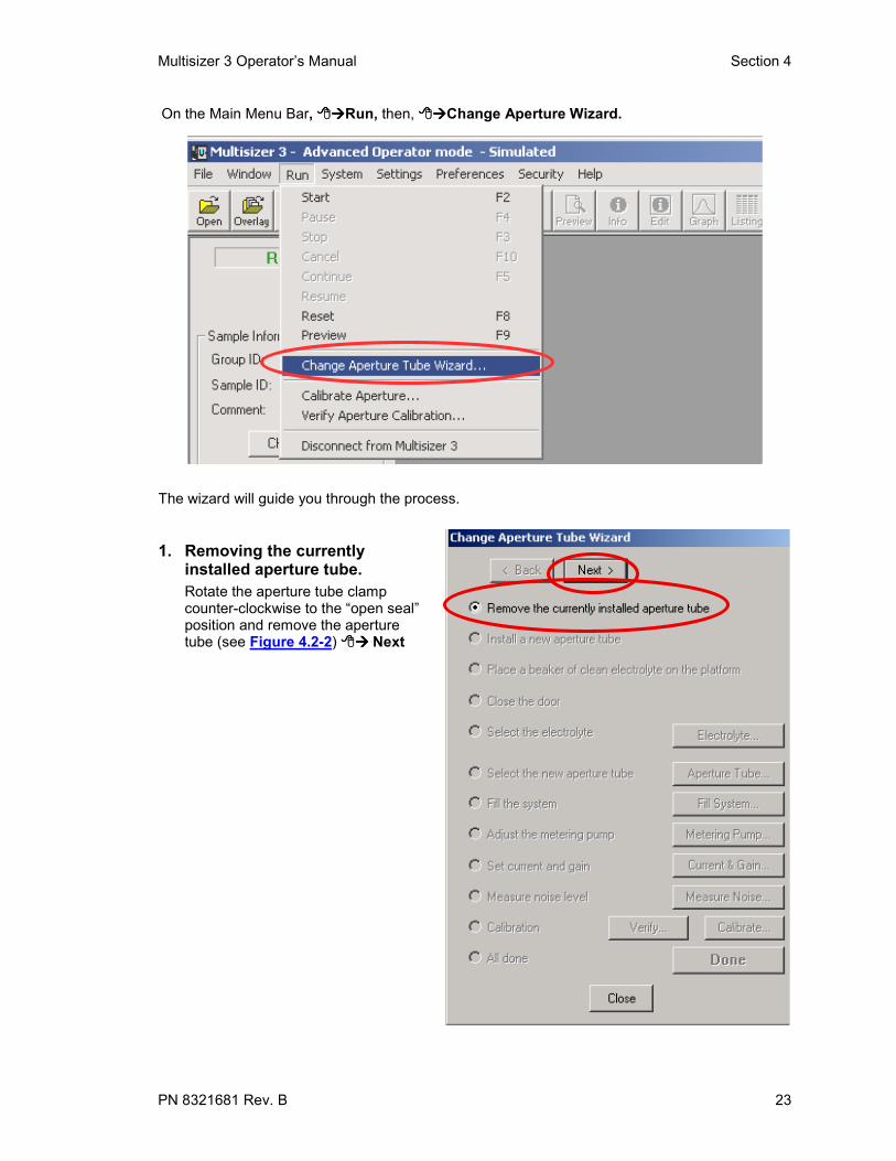
On the Main Menu Bar, Run, then, Change Aperture Wizard.
The wizard will guide you through the process.
1. Removing the currentlyinstalled aperture tube.Rotate the aperture tube clampcounter-clockwise to the “open seal”position and remove the aperturetube (see Figure 4.2-2) Next

Section 4 Multisizer 3 Operator’s Manual
24 PN 8321681 Rev. B
2. Installing a New Aperture Tube.
From the table below, select an aperture tube appropriate to the sample to be analyzed.
Aperture Size (µµµµm) Analysis Range (µµµµm)20 0.4 - 12.0
30 0.6 - 18.0
50 1.0 - 30.0
70 1.4 - 42.0
100 2.0 - 60.0
140 2.8 – 84.0
200 4.0 – 120.0
280 5.6 – 168.0
400 8.0 – 240.0
560 11.2 – 336.0
1000 20.0 – 600.0♦
2000 40.0 – 1200.0♦
♦ Range depends on sample density
Install the selected tube following the procedure describedin Section 4.2. Next.

Multisizer 3 Operator’s Manual Section 4
PN 8321681 Rev. B 25
3. Placing a beaker of clean electrolyte onthe platform. After placing the beaker with clean electrolyteon the platform, fill the electrolyte containerwith the same kind of electrolyte being used inthe beaker. Next.
4. Closing the Sample Compartmentdoor.Raise the platform with the beaker to the appropriate height and close the door. Next.

Section 4 Multisizer 3 Operator’s Manual
26 PN 8321681 Rev. B
5. Selecting theelectrolyte. Electrolyte.
From the drop downlist select theelectrolyte to be used.If the electrolyte is noton the list, type thename in the box. Youcan also select thedispersant to be used,or type its name if it isnot on the list. Afterselecting theelectrolyte anddispersant, OK.Be Sure to have thebeaker and electrolytecontainer filled with thesame electrolyteselected
6. Selecting theaperture tube.
Aperture TubeFrom the drop down listSelect the aperture tubeinstalled in 4.4 step 2.The first time a newaperture is installed, thedefault aperture isselected from thelist. OK.

Multisizer 3 Operator’s Manual Section 4
PN 8321681 Rev. B 27
7. Filling the System. Fill System
8. Adjusting the Metering Pump. Metering Pump

Section 4 Multisizer 3 Operator’s Manual
28 PN 8321681 Rev. B
9. Setting Current and Gain. Current & Gain, Auto Set. When the instrument is done setting the current and gain,OK. If you are analyzing cells, Cells, and OK.
If cells are to be analyzed, it is very important to select cells in this step. Notselecting cells could cause their damage due to a higher current setting.

Multisizer 3 Operator’s Manual Section 4
PN 8321681 Rev. B 29
10. Measuring Noise Level.
11. Calibration and Verification of theCalibration If the installed aperture is going to beused for first time, it needs to becalibrated. Now is the time to do this. Fora previously calibrated aperture, theverification of the calibration can be doneat this time. For details on the calibrationand verification procedures, refer toSection 5. If calibration is not necessary,
Next, Done
Measure Noise.

Section 4 Multisizer 3 Operator’s Manual
30 PN 8321681 Rev. B
4.5 Aligning the OpticsThe three knobs on the side of the instrument are used to align and focus the apertureimage in the display window. The two bottom knobs are labeled with a horizontal and avertical arrow. The horizontal adjusting knob causes the aperture image to move leftand right on the display window. The vertical adjusting knob causes the aperture imageto move up and down on the display window. The top knob labeled with an “eye”,focuses the image on the display window. Adjust the three knobs until the apertureimage is centered on the Aperture Viewer (see Figure 4.5.1).
Re-adjust the focus to obtain a well contrasted aperture image. If good contrast isimpossible to obtain, it may be necessary to reposition the beaker slightly, particularly ifthe beaker has a flat bottom and tall form.
Figure 4.5.1 Optics Alignment Knobs
Remember that the image in a microscope is always upside downand horizontally reversed - it always moves the opposite way to theadjustment.
Back to TOC

Multisizer 3 Operator’s Manual Section 5
PN 8321681 Rev. B 31
SECTION 5 CALIBRATION AND VERIFICATION OFCALIBRATION
5.1 Choosing the CalibratorAfter installing the aperture as described in Section 4, choose the appropriate calibratorsize according to the installed aperture. The calibrator must to be standardize for themodal value and provide its value. Beckman Coulter offers a variety of calibratorsuitable for the Multisizer 3.
ApertureSize (µµµµm)
Calibrator NominalModal Size (µµµµm)
Recommended BeckmanCoulter CC Calibrator
Nominal Modal Size (µµµµm)
20 2 – 4 2
30 3 – 6 3
50 5 – 10 5
70 7 – 14 10
100 10 – 20 10
140 14 – 28 20
200 20 – 40 30
280 28 – 56 30
400 40 – 80 43
560 56 –128 65
1000 60 – 150 90
2000 90 – 260 90
Table 5.1-1 Calibrators and size range for the calibration run
Beckman Coulter is not responsible for erroneous results if the propercalibrator and calibration procedure is not used.
5.2 Preparing the Calibrator1 Place an ACCUVETTE® or a beaker* with the electrolyte and a few drops of the
calibrator into the analyzer unit.
*An ACCUVETTE® (20 mL) is appropriate for apertures up to 100µm, for largerapertures a larger beaker should be used.

Section 5 Multisizer 3 Operator’s Manual
32 PN 8321681 Rev. B
2 On the Status PanelPreview, or in the Main
Menu, Run, Preview.
3. On the concentration index bar, verify that theconcentration indicates OK; try to be as close as possible to10%. If the concentration is high it can lead to an incorrectcalibration. If the concentration is too low, the calibration willtake a longer time to be completed. Adjust the concentrationif it is necessary. When done, Cancel.

Multisizer 3 Operator’s Manual Section 5
PN 8321681 Rev. B 33
5.3 Running the Calibrator1. On the tool bar click on the calibration icon, or on the Main Menu Bar,
Run, Do a Calibration Run.
2. On the Calibrator Size box enter the modal value of the calibrator. This value appears on theassay sheet of the calibrator.

Section 5 Multisizer 3 Operator’s Manual
34 PN 8321681 Rev. B
3. Start.
4. When the calibration run is completed, Accept New Kd. The instrument iscalibrated
It is convenient as a future reference to clearly identify the calibration files. These filescan be saved in the folder Calibration located in C:\MS.

Multisizer 3 Operator’s Manual Section 5
PN 8321681 Rev. B 35
5.4 Obtaining the mean KdFor more consistent results we recommend the first time an aperture is calibrated toperform the following procedure:
(1) Complete steps 5.1 through 5.3 ten times.
(2) Record the Kd value for each calibration. Calculate the mean for the 10 values.
(3) The mean for the Kd is only valid for the set aperture tube/electrolyte/instrumentused for the calibration. In future calibrations the Kd should always be within ±4%of the mean value from Step 5.4.2. The next table shows an example using a 10µm calibrator and a 100µm aperture tube.
Run Kd
1 124.15
2 125.82
3 125.13
4 125.23
5 125.43
6 125.13
7 124.25
8 125.62
9 124.25
10 125.03
MEAN 125.00
5.5 Entering the mean value for the Kd in the aperture list1. On the Main Menu Bar, Run, then Change Aperture Wizard.
2. On the Change Aperture Wizard, Next to skip the steps up to Aperture Tube.Aperture Tube, in the new box, Edit List. On the Edit List Box, on the
list the aperture size you just calibrated. Enter the serial number for the aperturetube, mean Kd value and Update.

Section 5 Multisizer 3 Operator’s Manual
36 PN 8321681 Rev. B
1
2
3
4
5 6
3. OK
4. the edited aperture and OK

Multisizer 3 Operator’s Manual Section 5
PN 8321681 Rev. B 37
5. Close
5.6 Verifying the calibrationAs the Multisizer 3 uses constant current, the instrument holds the calibration practicallyfor indefinite time provided that the same aperture tube/electrolyte combination is usedand the working conditions are stable. The calibration can be verified using the followingprocedure:
1. Place an ACCUVETTE® or a beaker* with the electrolyte and a few drops of thecalibrator into the analyzer unit.
*An ACCUVETTE® (20 mL) is appropriate for apertures up to 100µµµµm, for largerapertures a larger beaker should be used.
2. On the Status Panel Preview,or in the Main Menu,
Run, Preview.

Section 5 Multisizer 3 Operator’s Manual
38 PN 8321681 Rev. B
3. On the concentration index bar, verify that theconcentration indicates OK. Try to be as close as possibleto 10%. If the concentration is high it can lead to anincorrect result. If the concentration is too low, theverification will take a longer time to be completed. Adjustthe concentration if it is necessary. When done,
Cancel.
4. On the tool bar click on the verification icon, or on the Main Menu Bar Run and Verify Aperture Calibration.

Multisizer 3 Operator’s Manual Section 5
PN 8321681 Rev. B 39
5. On the Calibrator Size box enter the modal value of the calibrator. This value appears on theassay sheet of the calibrator. To choose the appropriate calibrator, refer to Table 5.1.1
6. Start.
7. When the run is completed, the dialog box will indicate the status of the calibration. If itindicates verification is OK, Close. If the instrument is out of calibration, go to Step 5.2
and 5.3.It is convenient as a future reference to clearly identify the verification files. These files canbe saved in the folder Verification located in C:\MS. Back to TOC

Section 6 Multisizer 3 Operator’s Manual
40 PN 8321681 Rev B
SECTION 6 SAMPLE ANALYSIS6.1 Introduction
At the start of each analysis, it is good practice to check each item in the following listeven though no change may be required from previous instrument settings.
Before running an analysis, the instrument must be in the following condition:
(4) The system has been filled with electrolyte.
(5) The correct aperture has been fitted.
(6) A beaker with clean electrolyte has been placed on the platform.
(7) The aperture is immersed into the electrolyte contained in the beaker
(8) The electrolyte container is sufficiently filled (enough to raise the level sensor).
(9) The Waste container is empty (enough to lower the level sensor).
(10) The Multisizer 3 and the computer have been powered on with the controlprogram running.
(11) The appropriate analysis settings have been selected.
These settings are the essential parameters that must be established before theanalysis to ensure that the particle pulses measured by the Multisizer 3 are optimallypositioned within the digital converter range and have the best signal to noise ratio.Other parameters that in previous instrument designs have had to be preset, such as thenumber of channels of data, can be changed after, or even during an analysis. TheAnalysis Settings menu can be found on the main menu bar.

Multisizer 3 Operator’s Manual Section 6
PN 8321681 Rev. B 41
6.2 Changing Standard OperatingMethod (SOM).
Change on the SOM sub-panelin the Status Panel, or on the MainMenu bar, Settings, and
Change SOM.
6.2.1 Selecting the Control ModeSelect the appropriate control radio button on theControl sub-panel (refer to Table 6.2-1). Enter thevariable associated with the method in the field.• Time. Any time up to 99999 seconds can beentered. The analysis will stop when the selectedtime has elapsed.• Volumetric. Any volume up to 2000µL can beentered. The analysis will stop when the selectedvolume has been analyzed. Use this mode onlywith apertures not larger than 280µm. (SeeSection 6.8).• Total Count. The number for total count canbe selected up to 525,000. The analysis will stopwhen the number corrected for coincidencecorresponding to the selected raw count numberhas been accumulated.• Modal Count. This is the number of particlescounted in the modal channel. The modal countnumber can be selected up to 525,000 counts.• Manual. The analysis has to be manuallystopped.

Section 6 Multisizer 3 Operator’s Manual
42 PN 8321681 Rev B
Control ModeAnalysis for:Manual Modal Count Total Count Time Volumetric
Size Distribution √ √ √ √ √
ParticleConcentration
No No No ♦ √
♦Refer to Section 6.8Table 6.2.1 Selecting the control mode for the analysis
6.2.2 Selecting the number of runs
You can select to run single or multipleruns. Selecting multiple runs allows you toinsert a delay time between runs. Whenmultiple runs are selected, the average ofthe runs can be automatically saved andprinted by checking the appropriateboxes.
6.2.3 Selecting the threshold
1. In the SOM dialog box Threshold
The threshold is the size above whichparticles are counted. It is also the lower limit of the size distribution. This setting CAN NOT be changed during or after the analysis.
Multisizer 3 Operator’s Manual Section 6
PN 8321681 Rev. B 43
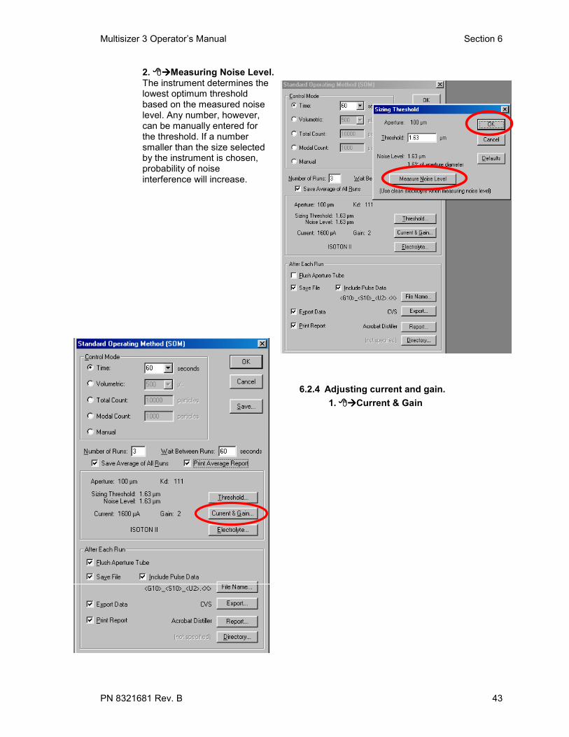
2. Measuring Noise Level.The instrument determines thelowest optimum thresholdbased on the measured noiselevel. Any number, however,can be manually entered forthe threshold. If a numbersmaller than the size selectedby the instrument is chosen,probability of noiseinterference will increase.
6.2.4 Adjusting current and gain.1. Current & Gain

Section 6 Multisizer 3 Operator’s Manual
44 PN 8321681 Rev B
2. Auto Set
3. Select Particles or Cells. OK
If cells are to beanalyzed, it is very importantto select cells in this step. Notselecting cells could causethem to be damaged due to ahigher current setting.
Every time the currentand gain are adjusted, it isnecessary to measure thenoise level.
6.2.5 Changing the Electrolyte
If you need to use a different electrolyte with the same aperture tube, perform thefollowing procedure:

Multisizer 3 Operator’s Manual Section 6
PN 8321681 Rev. B 45
1. Electrolyte
2. Select the electrolyte by double clicking in the drop down list or typing its name in the box.
3. If a dispersant agentis used, select it bydouble clicking in thedrop down list ortyping its name in thebox.
Section 6 Multisizer 3 Operator’s Manual
46 PN 8321681 Rev B
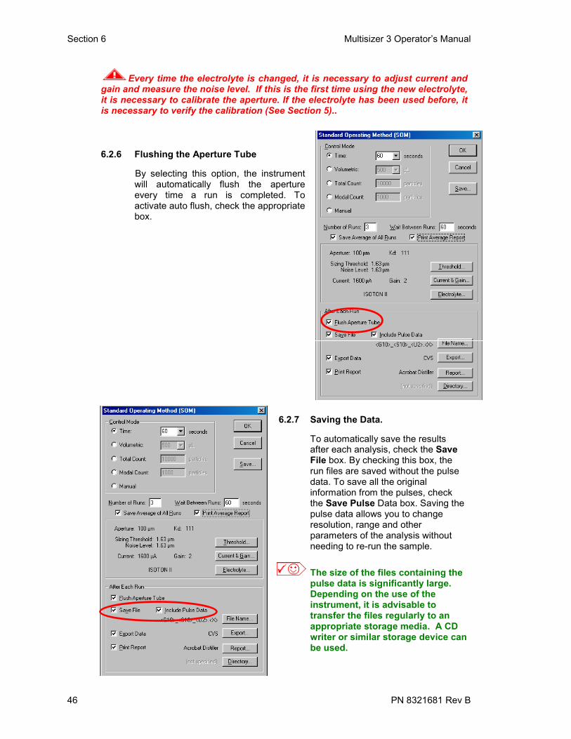
Every time the electrolyte is changed, it is necessary to adjust current andgain and measure the noise level. If this is the first time using the new electrolyte,it is necessary to calibrate the aperture. If the electrolyte has been used before, itis necessary to verify the calibration (See Section 5)..
6.2.6 Flushing the Aperture Tube
By selecting this option, the instrumentwill automatically flush the apertureevery time a run is completed. Toactivate auto flush, check the appropriatebox.
6.2.7 Saving the Data.
To automatically save the results after each analysis, check the Save File box. By checking this box, the run files are saved without the pulse data. To save all the original information from the pulses, check the Save Pulse Data box. Saving the pulse data allows you to change resolution, range and other parameters of the analysis without needing to re-run the sample.
The size of the files containing the pulse data is significantly large. Depending on the use of the instrument, it is advisable to transfer the files regularly to an appropriate storage media. A CD writer or similar storage device canbe used.

Multisizer 3 Operator’s Manual Section 6
PN 8321681 Rev. B 47
6.2.8 Generating the File NameTo identify the files from different analyses, a file name should be generated. Theoperator can customize it by checking the boxes of the information to be part of the filename. On the Standard Operating Method dialog box, File Name. In the FileGeneration Name Dialog box, customize name, Use Example and OK.
6.2.9 Exporting DataTo automatically export the analysis data after each run is completed, check the ExportData box. To select the export data format and destination, Export, select theoptions and OK.

Section 6 Multisizer 3 Operator’s Manual
48 PN 8321681 Rev B
6.2.10 Printing the Analysis ReportTo automatically obtain a printed report of the analysis after completing each run,
Report.Select the content of the printed report and OK.
6.2.11 Changing the Destination Directory.Directory, by checking the appropriate boxes, the run may be saved in the current
directory or in a different directory. To select the new directory Browse or thedrop down arrow. When done, OK.

Multisizer 3 Operator’s Manual Section 6
PN 8321681 Rev. B 49
At this moment the Standard Operating Method has been selected. In the Standard OperatingMethod Panel, OK.
6.3 Convert Pulses to SizeSettingsAlthough these settings can bechanged during or after theanalysis, it is convenient to selectthese settings before the analysis.In this way, they can be saved withthe Standard Operating Method.
1. L Settings, L ConvertPulses to Size Settings.

Section 6 Multisizer 3 Operator’s Manual
50 PN 8321681 Rev B
2. Select the settings
• Size Bins. Thenumber of size bins canbe selected from 4 up to300. Higher resolution isachieved when a largernumber of channels isselected.
• Bin Spacing.Use Logarithmic whenthe X axis units arelogarithmic, use Linear
when the X axis units are linear. Use Diameter to have the X-axis is in diameter units, usevolume to have the X axis in volume units.
• From – To. Enter the desired range for the analysis. The range can be selected from thethreshold size up to the size of the aperture.
The size distribution is guaranteed to be linear from 2 to 60% of the aperturediameter.
• Multisizer II Edit. This function is similar as in the Multisizer IIe. It is used to correct fornon-axial pass of particles through the aperture. It can be used only with narrow sizedistributions.
6.4 Saving Standard Operating MethodAll the settings for the analysis can be saved for future use. The saved file containing theStandard Operating Method can also be used to create a Standard OperationProcedure (SOP) (see Section 9).To save the Standard Operating Method Settings on the Main Menu bar and then
Save SOM.
The SOM file can be saved in the SOM folder located in C:\MS\SOP. Any number ofSOM files can be saved; they can be used at a later time for creating a StandardOperating Procedure (see Section 9).

Multisizer 3 Operator’s Manual Section 6
PN 8321681 Rev. B 51
To use a Standard Operating Method previously saved, Settings on the MainMenu bar, then Load SOM. To change the Standard Operating Method,
Change SOM.
6.5 Entering Sample InformationBy entering the sample information, it is possible to save all the information regardingthe sample in the same file for the analysis. When the determination of concentration isneeded, (counts/ml or counts/g), it is necessary to enter additional information in orderfor the software to do the calculation.
1. Change on the Sample Information sub-panel in the Control Panel,
or System on the Main Menu bar Enter Sample Info...

Section 6 Multisizer 3 Operator’s Manual
52 PN 8321681 Rev B
2. In the dialog box, enter all the required information.
Group ID, Sample ID, Operator, Bar Code and Comment are optional fields andtheir only purpose is to identify and classify the analyses. The run number willtrack the analyses sequence of each Group ID.
If it is necessary to determine the concentration of particles in thesample (counts), the followings fields must be filled in.
Sample volume or mass: This is the weight or volume of sample used.for the analysis.
Electrolyte volume: This is the volume of electrolyte used for the analysis.
Analytical volume: This is the volume of sample analyzed.

Multisizer 3 Operator’s Manual Section 6
PN 8321681 Rev. B 53
Other fields in the Enter Sample Info dialogue box.Variable 1 and Variable 2: These fields won’t affect the results and are just to enter anyvariable you would like to save in the sample information.Shape Factor: If a constant correction is needed, a factor can be entered and it willaffect the results. For example, if a fibrous material is analyzed and instead of theequivalent spherical diameter, the length is required, a conversion factor can be enteredto compensate for the difference in shape.File Name: This button has the same function as described in Section 6.2.8Control Sample: By checking this box, you indicate that the sample to be analyzed is acontrol sample.Density: This information needs to be entered if the mass size distribution is required.

Section 6 Multisizer 3 Operator’s Manual
54 PN 8321681 Rev B
Use Dilution Factor: By checking this box, it is posible to use a factor if dilution hasbeen used when preparing the sample. The dilution factor will affect the results.
Sample Statistics: When a sample is selected as “Control Sample”, its statisticalparameters and acceptable limits can be entered here.
To use the Sample Statistics as a reference, save this control sampleunder an easily identifiable name.

Multisizer 3 Operator’s Manual Section 6
PN 8321681 Rev. B 55
This information can be use as reference or specification for other samples. When done,OK.
6.6 Running a Background.The background is an analysis of the electrolyte without sample material; it is also calleda “Blank Analysis”. It is advisable to run a background for every batch of analyses in asingle day using the same electrolyte.
When analyzing low concentration samples, it isabsolutely necessary to run a background.
1. Select the same settings and parameters that will beused for the sample analyses.
2. Place the beaker with clean electrolyte in the analyzerunit.
3. Start in the Status Panel.

Section 6 Multisizer 3 Operator’s Manual
56 PN 8321681 Rev B
After the run is completed and saved, it can be automatically subtracted from eachsubsequent analysis.
6.7 Subtracting the Background1. On the main menu, Settings, Load Background Run.
2. Select the background run.
3. Double click on the background file or select the file and Open. From thispoint on, the background run will be automatically subtracted from each

Multisizer 3 Operator’s Manual Section 6
PN 8321681 Rev. B 57
subsequent analysis. To disable background subtaction, on the main menu,Settings, then Remove Background Run.
6.8 Running the Sample
1. Place the beaker with the sample in theanalysis unit. Preview in the Status Panel,or Run on the Main Menu bar Preview.
2. Check the sample concentration. The indexmeter must be below 10%. Adjust theconcentration as necessary. When done
Start in the Status Panel.

Section 6 Multisizer 3 Operator’s Manual
58 PN 8321681 Rev B
6.9 Determination of Particle Concentration Using a 400µµµµm Aperture or largerWhen using a large aperture (400µm and larger) to determine particle concentration, it isnot practical to use the volumetric control mode. If the volumetric control mode is used,the maximum volume allowed by the metering pump is 2 mL. Using a large aperturetakes a very short time to pass 2 mL through the aperture. Since there is a limit for theappropriate concentration of sample, the numbers of particles counted are not enough toobtain good statistical results and therefore a poor reproducibility will achieved. Theelectrolyte used with large apertures should be thickened to avoid noise due to a highflow rate. It will also help in suspending heavy particles. As thickening agents, glycerol,sucrose and others can be used.
Measure exactly the volume of electrolyte needed to fill the beaker to about9/10 of its capacity.
1. Set the instrument in Time Mode to 60 seconds.
2. Run the electrolyte.
3. When the run is completed, measure accurately the volume of electrolyte left in the beaker.
4. Subtract the volume left from the original electrolyte volume.
5. Divide the resulting volume by 60. The result is the flow rate in ml/sec for this specificcombination of aperture and electrolyte.
6. Knowing the flow rate, the Time Mode can be used to determine particle concentration. Thevolume of sample for the analysis is calculated using the flow rate. This volume is the“Analytical Volume”.
6.10 Cleaning the SystemIt is advisable to clean the system at the end of the day if the Multisizer 3 has beenunder any of the following working conditions.
• Analysis of biological samples
• Analysis of foods
• Use of corrosive fluids
6.10.1 Cleaning Procedure1. Disconnect the electrolyte reservoir from the instrument.
ElectrolyteReservoir
Disconnect here

Multisizer 3 Operator’s Manual Section 6
PN 8321681 Rev. B 59
2. On the main menu, System, Drain System.
3. After the drain of the system is completed, in place of the electrolyte reservoir,connect a reservoir dedicated to holding the cleaning agent. The recommendedcleaning agents for biological or food applications are Coulter Clenz or 2% bleachsolution. For all other applications, DI water is suitable.
4. On the main menu, System, Fill System.
5. Repeat step 3.
6. Leave the system filled with the cleaning agent until the next working day.
7. Before start using the instrument on the next working day, follow steps 1 trough 4,but in this case, switching back to the electrolyte.
Back to TOC

Section 7 Multisizer 3 Operator’s Manual
60 PN 8321681 Rev. B
SECTION 7 REVIEWING AND SAVING THE RESULTS7.1 Introduction
While an analysis file is open it can be viewed, changed and saved in many differentformats by using the commands and options described in this section.
7.2 Opening a FileTo open a previously saved file, on the main menu, File, Open.
Or on the tool bar the Open icon.

Multisizer 3 Operator’s Manual Section 7
PN 8321681 Rev. B 61
The Open command automatically displays the Open dialog box. To open the Demodatafile, the file and, Open.
By checking the Quick View box, it is possible to preview the files. The files can bepreviewed for size, trend or pulses by selecting the option from the drop down menu atthe right of the Quick View box. To preview a file, the file name.

Section 7 Multisizer 3 Operator’s Manual
62 PN 8321681 Rev. B
To open any of the files, the file name and Open.

Multisizer 3 Operator’s Manual Section 7
PN 8321681 Rev. B 63
7.3 Overlaying FilesThe Multisizer 3 software allows you to view more than one data file on the same graph.This is useful when you want to view point-by-point data comparisons using the samegraph.
To open the data files for overlay, File then Overlay on the main menu, or on thetool bar, the Overlay icon.
The Overlay dialog box will be displayed.

Section 7 Multisizer 3 Operator’s Manual
64 PN 8321681 Rev. B
To Overlay files, to highlight the file name. Add in the bottom of the dialog box.Repeat this step to select all the files to overlay. When you have finished choosing thefiles, OK. To overlay consecutive files, to highlight the first file name, hold downthe left mouse button and drag to highlight all the required files then Add, and
OK.
A graph containing data from all selected files is displayed. The legend that appears inthe upper right-hand corner of the graph displays the names of the data files used in theoverlay.

Multisizer 3 Operator’s Manual Section 7
PN 8321681 Rev. B 65
To add an additional file to an already existing overlay, Run File, then Open forOverlay on the second level menu, or Overlay (second icon) on the tool bar.
The Open for Overlay dialog box will appear automatically. Select the file to be addedto the existing overlay and Open.

Section 7 Multisizer 3 Operator’s Manual
66 PN 8321681 Rev. B
The selected file will be added to the existing overlay.
The Overlay can be saved as an Overlay File. To save an Overlay, on the second levelmenu, Run File, Save Overlay.
The Save Overlay dialog box will appear automatically. Assign a name for the OverlayFile and Save.

Multisizer 3 Operator’s Manual Section 7
PN 8321681 Rev. B 67
To open an Overlay File, on the main menu, File, Open Overlay.
The Open Overlay dialog box will appear automatically. Select the file and Open.The file will be added to the Overlay.
This file is linked to the source files. It means that the file may onlybe opened when the original files are in the location from where theoverlay file was saved.
7.4 Averaging FilesThe averaging function allows data from multiple data files to be averaged together. Datafrom individual files are combined, channel contents are averaged, sample statistics foreach channel are calculated and the distribution is plotted on a single graph. Theresultant file provides a graphical representation of the averaged contents of eachchannel.

Section 7 Multisizer 3 Operator’s Manual
68 PN 8321681 Rev. B
To average files, on the main menu, File, Average.
The Average dialog box will appear automatically.
For averaging files, file name. Add in the bottom of the dialog box. Repeat thisstep to select all the files to overlay. When you have finished choosing the files, OK.To Average consecutive files, to highlight the first file name, hold down the mouseleft mouse button and drag to highlight all the required files, Add and then OK.

Multisizer 3 Operator’s Manual Section 7
PN 8321681 Rev. B 69
To add an additional file to an already existing Average, on the second levelmenu, Run File, Open and Add to Average.

Section 7 Multisizer 3 Operator’s Manual
70 PN 8321681 Rev. B
The Open dialog box will appear automatically. Select the file and Open. The filewill be added to the Average.
The Average file can be saved. On the second level menu, Run File, Save.

Multisizer 3 Operator’s Manual Section 7
PN 8321681 Rev. B 71
The Save As dialog box will appear automatically. Assign a name for the File andSave.

Section 7 Multisizer 3 Operator’s Manual
72 PN 8321681 Rev. B
7.5 Creating a Size TrendSize Trend is most often used to show statistics from a number of sample runs on onegraph or report. This would be useful, for example, in a manufacturing process where asample is measured with the Multisizer at specific time intervals, (minutes, hours, daysetc.). These data files can be used to create a trend graph or listing at the end of achosen period of time to track changes of selected statistical values. User-selectablepass/fail limits can also be shown on trend graphs and listings. The Size Trend can beupdated at any time by adding new points.
To create a Size Trend, on the main menu, File, Create Size Trend
.
The Create Size Trend dialog box will appear automatically.

Multisizer 3 Operator’s Manual Section 7
PN 8321681 Rev. B 73
To select the files to be included in the Size Trend, the file name. Once you havehighlighted the file name, Add in the bottom of the dialog box. Repeat this step toselect all the files for the Size Trend. When you have finished selecting the files,
OK. To select consecutive files, to highlight the first file name, hold down theleft mouse button and drag to highlight all the required files. Add, and OK.

Section 7 Multisizer 3 Operator’s Manual
74 PN 8321681 Rev. B
Additional files may be added to an already existing Size Trend. On the second levelmenu, Run File, Open and Add to Trend.
The Open dialog box will appear automatically. Select the file and Open. The filewill be added to the Size Trend.

Multisizer 3 Operator’s Manual Section 7
PN 8321681 Rev. B 75
The Trend file can be saved. On the second level menu, Run File, Save.
The Save As dialog box will appear automatically. Assign a name for the File andSave.

Section 7 Multisizer 3 Operator’s Manual
76 PN 8321681 Rev. B
7.6 Overlapping Files from Different Aperture Sizes.The Multi-Tube Overlap procedure is used to combine up to 5 distributions into a singledistribution with a new file name. This merging routine is able to create particle sizedistributions outside the range of any single aperture by combining 2 to 5 aperture sizeanalyses from the same sample.
Obtain a size distribution on the Multisizer analyzer with an aperture tube suitable for thecoarsest material in the sample. After analysis, sieve, filter or use any other suitablemethod to remove particles from the remaining suspension which are likely to block thesmaller aperture. Continue the analysis with the next smaller aperture.
To find the combined distribution, find the point or range where the plots are most“parallel”. This point, or range, is called the “offset point”. At this point the verticaldisplacement (or offset), between the two graphs is measured. For example, if at thechosen point the cumulative number oversize is 1,000 from the small aperture and10,000 from the large aperture, then the dilution is exactly 10:1.To combine the two plotsthe Multisizer 3 program multiplies the sample data from the small aperture by 10 andoverplots it on the large aperture plot. The program will then exclude the small aperturedata with a size larger than the offset point. The result is the combined distribution.
To create a Multi-Tube Overlap file, on the main menu, File, Multi-TubeOverlap.

Multisizer 3 Operator’s Manual Section 7
PN 8321681 Rev. B 77
The Multi-Tube Overlap dialog box will appear automatically. Up to five files may beselected to be included in the Multi-Tube Overlap. To select files the file name.Once you have highlighted the file name, Add in the bottom of the dialog box.Repeat this step to select all the files for the Multi-Tube Overlap. When you havefinished selecting the files, OK. To select consecutive files, to highlight the firstfile name, hold down the left mouse button and drag to highlight all the required files,
Add,.and OK.
A graph showing the slope ratio and offset appears automatically Try Fit.

Section 7 Multisizer 3 Operator’s Manual
78 PN 8321681 Rev. B
A graph containing the software proposal for the overlap is displayed. Accept Fit.
The size distribution graph for the resultant file will appear.

Multisizer 3 Operator’s Manual Section 7
PN 8321681 Rev. B 79
To save the file, on the second level menu, Run File, Save.
The Save As dialog box will appear automatically. Assign a name for the File andSave.
Back to TOC

Section 8 Multisizer 3 Operator’s Manual
80 PN 8321681 Rev. B
SECTION 8 PRINTING A REPORT8.1 Introduction
This section describes how to set up the Preferences Menu in order to customize theprinted report from the analysis. The Preferences Menu is found on the main menu,and after selecting the desired options, they can be saved as a preference file or as theDefault Preferences file. Saving these files allows the user to recall them in the futureand also to be used in the creation of a Standard Operation Procedure (SOP) (seeSection 9).
The Default Preferences file will determine how the format of the on-screen graph anddata is displayed when the program is started at the beginning of a working session.
The Preferences File in use will determine the format of the on-screen graph and datadisplayed in the following situations:
• During the length of the analysis.
• After the analysis is completed.
• When a file is opened
Samples of data files, chosen to illustrate how to work with them, are included in thesoftware’s Demodata directory and are installed in C:/MS/Demodata.
The way the on-screen results are displayed can be changed at any time while the filefor the run is open, but the printed report will be changed only if the Preferences File isaltered.
To access the Preferences Menu, go to the main menu and Preferences.
8.2 Selecting the Content of the Printed ReportThe Printed Report submenu is where the choices for the content of the report arefound. Once the selection of the content is done, they can be customized on thesubsequent submenus.
In the Preferences Menu, Printed Report.

Multisizer 3 Operator’s Manual Section 8
PN 8321681 Rev. B 81
8.2.1 Sample Info.Checking the Sample Info box allows you to place basic information about the analysison the report. The sample information enterd by the operator in Section 6.5 can bereported in two formats, standard and short.
Example for standard Sample Info:
Multisizer 3 3.5120 May 2001File name: 14931s1.#01Group ID: 14931s1Sample ID: A11Operator: ALRun number: 1Electrolyte: 4% NaCl IN H2ODispersant: NoneAperture diameter: 30 µm Kd: 42.393Aperture current: -800 µA Gain: 4Size bins: 256 from 0.6 µm to 18 µmSigma: 7087 (Coincidence corrected)Count > 0 µm: 0 Coincidence corrected: 0Coincidence correction: 0.0%Control method: Volumetric, 500 µLAcquired: 9:19 30 Mar 2000Electrolyte volume: 20 mLAnalytic volume: 500 µLSample: 2.5 mLBackground run: 14931.#01

Section 8 Multisizer 3 Operator’s Manual
82 PN 8321681 Rev. B
Example for short Sample Info:
Multisizer 3 3.5120 May 2001File name: 14931s1.#01Group ID: 14931s1Sample ID: A11Size bins: 256 from 0.6 µm to 18 µmSigma: 7087 (Coincidence corrected)Acquired: 9:19 30 Mar 2000Background run: 14931.#01
8.2.2 Size Section of the Printed Report
1. Size GraphBy checking the Graph box, the size distribution histogram for the samples will appear on thePrinted Report. Different options are available for the size distribution Graph. To select theseoptions, Select and a dialog box containing all the options for the Graph will pop up. Afterselecting the format of the Graph, OK.

Multisizer 3 Operator’s Manual Section 8
PN 8321681 Rev. B 83
2. Size StatisticsThe Statistics for the samples will be contained in the Printed Report by checking thecorresponding box. In Section 8.3 is described how to select the statistics parameters tobe shown on the report.
3. Averaged StatisticsWhen several runs are averaged, the statistics of the resultant run can be obtained onthe printed report by selecting the Averaged Statistics option.

Section 8 Multisizer 3 Operator’s Manual
84 PN 8321681 Rev. B
4. Compare StatisticsThe Multisizer 3 software allows one data file to be used as a statistical standard towhich other data files may be compared. Limits from this standard file can also beapplied to other data files.To use the Compare Statistics function set up, as described below, a data file to serveas a standard file against which other files will be compared. When a sample is selectedas control and its statistics are entered in the Sample Info box, this run can be used as areference to compare to other runs (see Section 6.5). If a file from a sample was notselected as Control Sample at the time of the analysis, and it is required to CompareStatistics, the following procedure can be used.1. Use the Open command as described in Section 7.2 to open the required file.
2. On the second level menu, Edit, Edit Sample Statistics.
3. In the Edit Sample Statistics dialog box, enter the statistics information: OK.Save the file.

Multisizer 3 Operator’s Manual Section 8
PN 8321681 Rev. B 85
To use the Sample Statistics as a reference, save this file under an easilyidentifiable name.
To display on the Printed Report the Compare Statistics, check the appropriate box inthe Printed Report dialog box.
5. Size ListingBy selecting the Listing option, a section containing a list of the data for each channel ofthe size distribution will be placed on the Printed Report.

Section 8 Multisizer 3 Operator’s Manual
86 PN 8321681 Rev. B
The format and content of the Listing can be selected by Select next to the Listing boxin the Printed Report dialog box.The Size Listing dialog box appears automatically. Select the desired options, then OK.
6. Size InterpolationThe Multisizer 3 software can be used to create sample data reports that will arrangedata to interpolate data to conform to a set of user defined boundaries, also called“channels”, “bins”, or “size classes”. (This is similar to how particle data points arereported when different size sieves are used.) The Multisizer 3 software refers to thisprocess as Size Interpolation.To include on the Printed Report the Interpolation Points, check the appropriate box inthe Printed Report dialog box.The format and arrangement of the data for the Interpolations Points can be selected by
Select next to the Interpolation box in the Printed Report dialog box.
The Size Interpolation dialog box appears automatically. When finished selecting theoptions, OK.

Multisizer 3 Operator’s Manual Section 8
PN 8321681 Rev. B 87
8.2.3 Size Statistic Section of the Printed ReportThis section of the Printed Report dialog box allows a choice of the statistic parameters tobe printed on the report. Here the formats of the size distributions from which the statisticis calculated can be selected as well.

Section 8 Multisizer 3 Operator’s Manual
88 PN 8321681 Rev. B
The kind of size distribution can be selected by checking the appropriate box.
Mass Number Number % Number/mL Volume
Volume % Volume/mL Surface Area Surface Area % Surface Area/mL
The Size Statistics dialog box appears when Select inside the Size Section.Choose the parameters needed on the Printed Report and OK.

Multisizer 3 Operator’s Manual Section 8
PN 8321681 Rev. B 89
8.2.4 Pulses Section of the Printed Report
1. Pulse GraphIf Pulse Data is saved as described in Section 6.2.7, the options to display and print thisinformation can be selected now. Check the appropriate box for including the PulseGraph in the Printed Report and select options by Select.
The Pulse Graph dialog box will appear. After selecting the options, OK.

Section 8 Multisizer 3 Operator’s Manual
90 PN 8321681 Rev. B
2. Pulse Listing
Check the appropriate box for including the Pulse Listing in the Printed Report andselect options by Select.
The Pulse Listing dialog box will appear. After selecting the options, OK.

Multisizer 3 Operator’s Manual Section 8
PN 8321681 Rev. B 91
8.2.5 Trend Section of the Printed Report
1. Trend GraphCheck the appropriate box for including the Trend Graph in the Printed Report andselect options by Select.
The Trend Graph dialog box will appear. After selecting the options, OK.

Section 8 Multisizer 3 Operator’s Manual
92 PN 8321681 Rev. B
2. Trend ListingCheck the appropriate box for including the Trend Listing in the Printed Report andselect options by Select.
The Trend Listing dialog box will appear. After selecting the options, OK.

Multisizer 3 Operator’s Manual Section 8
PN 8321681 Rev. B 93
8.2.6 Printer SectionThe default printer can be used to print the report or another printer attached to thecomputer can be selected.
8.2.7 Closing the Printing Report Dialog BoxAt this moment all the selections for the Printed Report have been made. OK.

Section 8 Multisizer 3 Operator’s Manual
94 PN 8321681 Rev. B
8.3 Customizing the PreferencesThis section describes how to set up the preference file. Section 8.2 described how toselect the options for some of the preferences, in this section they are explained in moredetail.
Size GraphSize ListingSize StatisticsSize Interpolation
Trend GraphTrend ListingPulse GraphPulse Listing
If you already made these selections, it is not necessary to modify them again.
8.3.1 SizeTo set up the Size Preferences, on the main menu Preferences and Size. Asubmenu showing the options for Size will appear.

Multisizer 3 Operator’s Manual Section 8
PN 8321681 Rev. B 95
1. Size GraphIn the Size submenu Size Graph. The dialog box containing the options to displayand print the Size Graph will appear. A separate graph will be printed for every boxchecked in the Distribution Types section.These graphs will be printed in the order theyare selected, and the printing order will be displayed in the lower left-hand corner of thedialog box.
Types of DistributionFor each kind of Size Distribution; (mass, number, number %, number/mL, volume,volume %, volume/mL, surface area, surface are % and surface area/mL), there are fivedifferent types of graph to choose from.
DifferentialDistribution.

Section 8 Multisizer 3 Operator’s Manual
96 PN 8321681 Rev. B
Cumulative <
Cumulative >
Differential + Cumulative <

Multisizer 3 Operator’s Manual Section 8
PN 8321681 Rev. B 97
Differential + Cumulative >
X Axis ScaleThe X axis scale may be displayed in either linear or logarithmic. The logarithmic scaleoffers more detail for the lower side of the distribution. When a file acquired on aMultisizer IIe is open using the Multisizer 3 software, it is advisable to choose the option“as accumulated”.
Linear X axis
Logarithmic X axis

Section 8 Multisizer 3 Operator’s Manual
98 PN 8321681 Rev. B
Other Options for the Size Graph Logarithmic Y axis Multisizer Cursors. This option shows where the cursors are placed when a file
acquired on the Multisizer IIe is open using the Multisizer 3 Software.
Y/dX Graph. Use Sample ID as Title. It places the sample ID entered in Step 6.5 as the graph
title.
When done selecting the Size Graph options, OK in the Size Graph dialog box.
2. Size ListingIn the Size submenu, Size Listing, the dialog box containing the options to display and printthe Size Listing will appear.
Selecting “Between Cursors” will display the Listing for only the channelswithin the range being used. When “All Bins” is selected, all the channelsfor the entire range of the aperture (2% to 60%), will be listed. “From”allows selection of the channel range for the Listing.
When done selecting the Size Listing options, OK in the Size Listing dialog box.
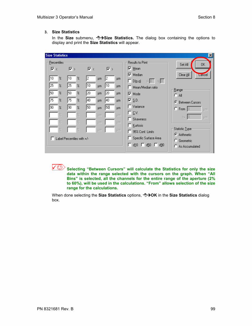
Multisizer 3 Operator’s Manual Section 8
PN 8321681 Rev. B 99
3. Size StatisticsIn the Size submenu, Size Statistics. The dialog box containing the options todisplay and print the Size Statistics will appear.
Selecting “Between Cursors” will calculate the Statistics for only the sizedata within the range selected with the cursors on the graph. When “AllBins” is selected, all the channels for the entire range of the aperture (2%to 60%), will be used in the calculations. “From” allows selection of the sizerange for the calculations.
When done selecting the Size Statistics options, OK in the Size Statistics dialogbox.

Section 8 Multisizer 3 Operator’s Manual
100 PN 8321681 Rev. B
4. Size InterpolationThe Multisizer 3 software may be used to create sample data reports that will arrangedata to interpolate in a set of user defined boundaries. This is similar to how particle datapoints are reported when different size sieves are used.Two types of interpolation format may be used. In the first format, the boundariesrepresent size classes. In the second format, the particle data are contained inpercentage classes. There are 3 choices: “Over”, “Under”, and “Differential”. You canredefine both the number of boundaries and the value assigned to each boundary.In the Size submenu, Size Interpolation. The dialog box containing the options todisplay and print the Size Interpolation will appear.
Selecting “Between Cursors” will calculate the Interpolation points for onlythe size data within the range selected with the cursors on the graph. When“All Bins” is selected, all the data for the entire range of the aperture (2% to60%) will be used in the calculations. “From” allows selection of the sizedata range for the calculation of the Interpolation points.
When done selecting the Size Interpolation options, OK in the Size Interpolationdialog box.

Multisizer 3 Operator’s Manual Section 8
PN 8321681 Rev. B 101
8.3.2 TrendTrend data is used to show statistics from a number of sample runs on one graph orreport. This would be useful, for example, in a process where a sample is measured atspecific time intervals. Trend files are widely used in quality control to track thecompliance of the product to established specifications. These data files can be used tocreate a trend graph or listing at the end of any desired period of time, and can beupdated as often as is necessary. On the main menu Preferences and Trend.A submenu showing the options for Trend will appear.
1. Trend GraphIn the Trend submenu, TrendGraph.The parameters in the larger section atthe left side of the dialog box can beselected for the Y-axis. The parameters inthe smaller section can be used on the X-axis. When done selecting the TrendGraph options, OK in the TrendGraph dialog box.
2. Custom PointsUp to three points can be customized.

Section 8 Multisizer 3 Operator’s Manual
102 PN 8321681 Rev. B
Trend ListingIn the Trendsubmenu,
Trend Listing.When finishedselecting the TrendListing options,
OK in theTrend Listingdialog box.
8.3.3 PulsesIf Pulse Data is saved as described in Section 6.2.7, the options to display and print thisinformation may be selected at this time. On the main menu Preferences and
Pulse. A submenu showing the options for Pulse will appear.
1. Pulse Graph

Multisizer 3 Operator’s Manual Section 8
PN 8321681 Rev. B 103
In the Pulse submenu, Pulse Graph.
Pulse Maximum High can be used for the Y-axis and Pulse Sequence or Pulse Width onthe X-axis. When finished selecting the Pulse Graph options, OK in the PulseGraph dialog box.
2. Pulse ListingIn the Pulse submenu, Pulse Listing.
When finished selecting the Pulse Listing options, OK in the Pulse Listing dialogbox.
8.3.4 Other Options for the Preference FileOn the main menu,
Preferences andView Options. A dialog
box will appear.

Section 8 Multisizer 3 Operator’s Manual
104 PN 8321681 Rev. B
1. X-Axis SectionThe units for the X-axis can be expressed as diameter, volume or surface area.Diameter: this is the most common use for the X-axisfor industrial applications.Volume: this is widely used in biological applicationsArea: this is used for specialized studies.As Accumulated: this option is used when a file acquired on the Multisizer IIe is opened using the Multisizer 3 software.
2. Measuring SectionParticles or Cells can be selected. This selection is used only for changing the X-axis units for displaying the data and /or printing the report. Where it is critical to select Cells is in Step 6.2.4.
3. Volume Units SectionWhen Diameter is used for the X-axis, units can be µ3 or fL. In cell biology, fL is more commonly used
4. Specific Surface Area UnitsWhen Surface Area is used for the X-axis, units can be selected as cm2/mL or m2/mL.
5. Multisizer 3 Pulse DataIn this box the number of pulses to be saved can be selected. Up to 525,000 pulses may be saved.
6. Z2 DataIf a file acquired on the Z2 is opened using theMultisizer 3 software, the last channel can besuppressed by checking this box.
7. ISO 9276 (Preliminary)The choice of having all units represented inaccordance with ISO 9276-1 (preliminary) is alsoincluded as an option for both graphs and listings.
8.3.5 Averaging and TrendingThe options for the weighting and type of distribution for the average and also the settingfor the limits averages and trends are located under Averaging and Trend.

Multisizer 3 Operator’s Manual Section 8
PN 8321681 Rev. B 105
On the main menu Preferences and Averaging and Size Trend. The followingdialog box will appear.
AverageOptions
Average and TrendOptions
The two boxes at the bottom of the dialog allow file names to be printed with their fullpath, and another option to add to the report all data points from the averaged or trendfiles.
Once the options have been selected, OK.
8.3.6 Number and Date FormatsThe Number and Date Format dialog specifies what number format will be used for datafiles that are being exported to other applications. This function also determines hownumbers are displayed in tabular data listings, and determines whether the Multisizersoftware represents the decimal point as a space, a comma or a period. The date canalso be formatted under this Preference option.
On the main menu, Preferences and Number and Date Format
Once the options have been selected, OK.

Section 8 Multisizer 3 Operator’s Manual
106 PN 8321681 Rev. B
8.3.7 Data ExportOptions in the Data Export dialog allow the user to specify which subsections of therunfile (e.g., the file header, size data, pulse data, etc.) will be exported. An extension,such as .xls, may be entered so that another application will recognize the exported data.Formatting options are also included in the Data Export dialog. On the main menu,
Preferences and Data Export.
Once the options have been selected, OK.
8.3.8 Graph OptionsThe Graph Options dialog box allows customizing the appearance of the graphs. In thisdialog, separate color, line or dot styles may be specified for each data file, and thedialog also includes options for grid lines and legend position. The colors and styles foreach file may be defined differently depending on whether the choices refer to a printeddocument or an on-screen display. On the main menu, Preferences and GraphOptions.
Once the options have been selected, OK.

Multisizer 3 Operator’s Manual Section 8
PN 8321681 Rev. B 107
8.3.9 Page SetupSelect this menu item to control printer functions, including printer set-up, margins, titlesand page orientation of printed output. Page Setup also allows inserting a company logoas a page header by entering the file name of a custom logo in bitmap format using theCustom Bitmap option. This can be created using Microsoft Paintbrush to make a blackand white or 16-color bitmap up to 600 pixels wide by 200 pixels high.The full path to the bitmap must be entered, e.g. ("c:\windows\ls\mylogo.bmp",). Thisbitmap will show up at the top left of every page printed, replacing the Beckman Coulterlogo. On the main menu, Preferences and Page Setup.
When the page setup has been selected, OK.
8.3.10 Pick FontsUse Pick Fonts to make changes in font type and font size. Separate settings areavailable for graphs, listings, statistics, and headers. The program allows previewing fontsize and font samples before making the choices. On the main menu Preferences,then Pick Fonts.
After making changes, Apply to implement changes, then OK.

Section 8 Multisizer 3 Operator’s Manual
108 PN 8321681 Rev. B
8.3.11 Windows ColorsChoices here will control the default colors for the text, warning text and the windowbackground. Preferences, and Windows Colors. After selecting colors for eachoption, OK.
These choices will not affect any other Windows applications.
8.3.12 Customize ToolbarThis option allows you to select wether to show or to hide the toolbar and the way thetoolbar buttons will be displayed. On the main menu Preferences, and,
Customize Toolbar.
After selecting options, Apply to implement changes, then OK.

Multisizer 3 Operator’s Manual Section 8
PN 8321681 Rev. B 109
8.3.13 Selecting the LanguageTo select the language, Preferences then Language.
The available languages will appear in the drop down menu of the language dialog box.After selecting the language, OK.
8.3.14 Saving PreferencesAt this moment all the options for the Preferences have been selected.
All the options for the Preferences can be saved for future use. To save thePreferences, Settings on the Main Menu bar and then Save Preferences As.
After assigning a name to identify it, the Preferences file can be saved in the sub-folderPreferences located in C:\MS\SOP. Any number of Preferences files can be saved;they can be used at a later time as the options to view the results and print the analysisreport or for creating a Standard Operating Procedure (see Section 9).

Section 8 Multisizer 3 Operator’s Manual
110 PN 8321681 Rev. B
To use a Preferences file previously saved, Preferences on the Main Menu bar, thenLoad Preferences. To change a Preferences file, Edit Preferences Info.
The Preferences options can also be saved as the Default Preferences. These defaultoptions will appear every time the Multisizer 3 program is started. To save Preferencesas default, Preferences on the Main Menu bar, then Save Preferences AsDefault.
Back to TOC

Multisizer 3 Operator’s Manual Section 9
PN 8321681 Rev. B 111
SECTION 9 CREATING A STANDARD OPERATINGPROCEDURE (SOP)
9.1 IntroductionThis section describes how to create and use Standard Operating Procedures (SOP).This feature of the software allows you to combine Preferences files and StandardOperating Methods (SOM) files into one single file. This new file will include all thenecessary settings and options described in any user defined SOP. Creating and savingSOP’s is specially useful when more than one operator is using the Multisizer 3 or whenthe instrument is used for more than one type of application. The use of SOP’s alsoensures the consistency of the analyses by preventing an unauthorized operator tochange any of the settings or options included in the SOP, (see Section 10).
9.2 Creating and Saving an SOPBefore creating an SOP, it is necessary to create and save the Standard OperatingMethod (SOM) file and the Preferences file (see Section 6.2 to 6.4 and Section 8).
To create the SOP file, on themain menu Settings and inthe drop down list select Createan SOP.
The dialog box to selectthe necessary files forcreating the SOP willappear.
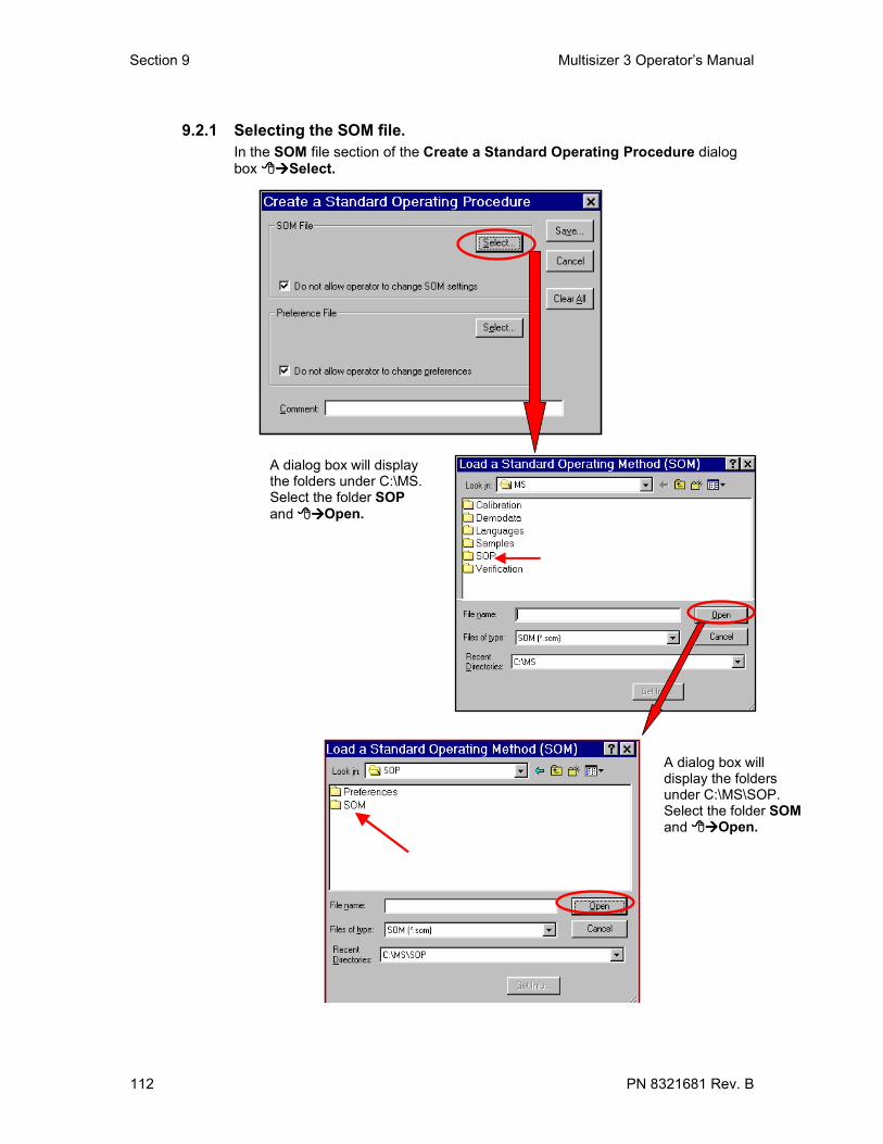
Section 9 Multisizer 3 Operator’s Manual
112 PN 8321681 Rev. B
9.2.1 Selecting the SOM file.In the SOM file section of the Create a Standard Operating Procedure dialogbox Select.
A dialog box will displaythe folders under C:\MS.Select the folder SOPand Open.
A dialog box willdisplay the foldersunder C:\MS\SOP.Select the folder SOMand Open.

Multisizer 3 Operator’s Manual Section 9
PN 8321681 Rev. B 113
After selecting the folder SOM, Open. All the previously saved SOM files willbe shown (see Section 6.4). Select the necessary file to be included in the SOPand Open.
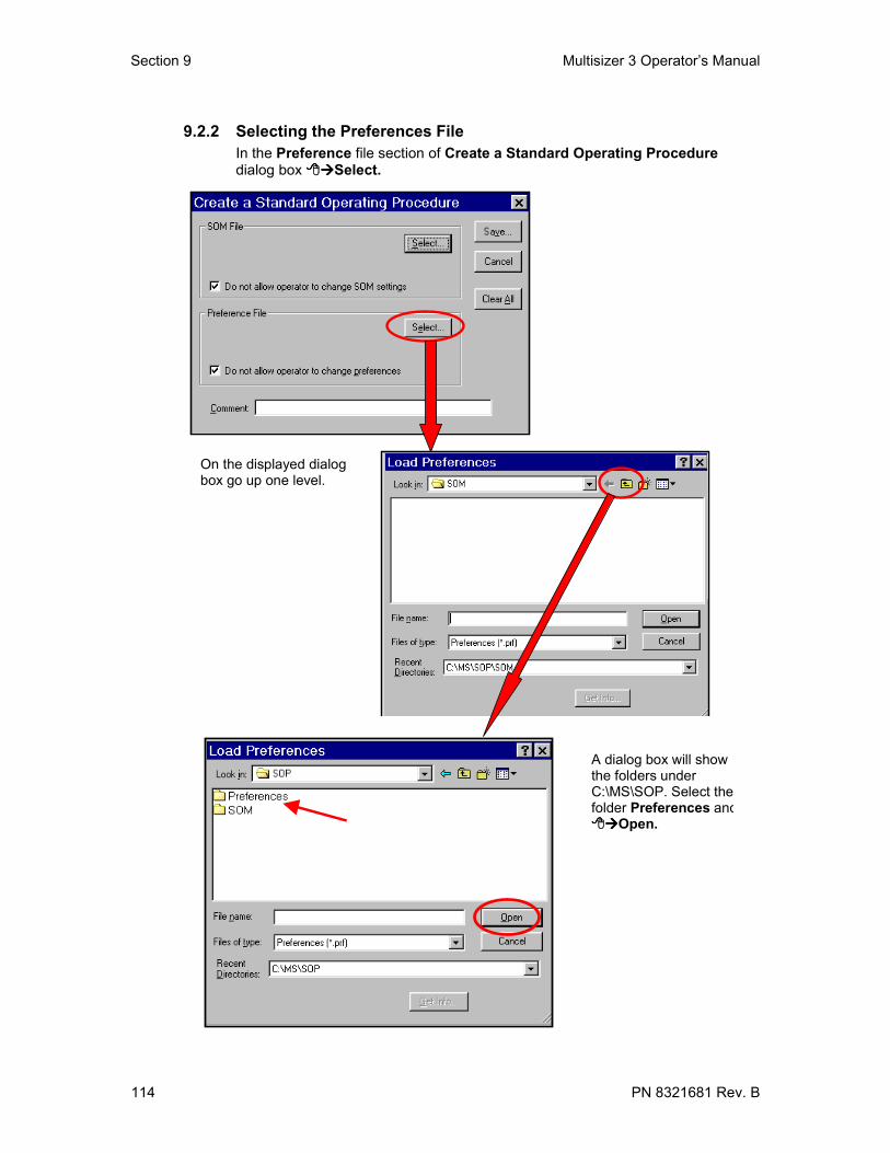
Section 9 Multisizer 3 Operator’s Manual
114 PN 8321681 Rev. B
9.2.2 Selecting the Preferences FileIn the Preference file section of Create a Standard Operating Proceduredialog box Select.
On the displayed dialogbox go up one level.
A dialog box will showthe folders underC:\MS\SOP. Select thefolder Preferences and
Open.

Multisizer 3 Operator’s Manual Section 9
PN 8321681 Rev. B 115
After selecting the folder Preferences, Open. All the previously savedPreferences files will be shown (see Section 8.3.14). Select the necessary fileto be included in the SOP and Open.
9.2.3 Saving the SOPAt this moment thetwo files needed tocreate an SOPhave beenselected. Acomment can beadded and it will beshown in the Infobox for the SOP(see Section 9.2).To save the SOP
Save.

Section 9 Multisizer 3 Operator’s Manual
116 PN 8321681 Rev. B
The SOP file can be saved for future use in the SOPfolder located in C:\MS.
9.3 Using an SOPAny number of SOP files can be created and saved for future use (see Section 9.1). Touse a previously saved SOP file, Settings on the main menu and select. Load anSOP.

Multisizer 3 Operator’s Manual Section 9
PN 8321681 Rev. B 117
A dialog box will show all the SOP files previously saved. Select the required SOP.The Get Info button shows a display of all the information about the selected SOPfile. To use the SOP file for analyzing samples in the Multisizer 3, OK.
9.4 Removing the Active SOPIf during a working session an SOP file is in use and a different file is needed, just followinstructions in Section 9.2 and load a new SOP file. This action will remove the previousfile from use. When there is no need for using an SOP file, the current file in use can beremoved.. Settings on the main menu and select Remove SOP.
Back to TOC

Section 10 Multisizer 3 Operator’s Manual
118 PN 8321681 Rev. B
SECTION 10 REGULATORY COMPLIANCE10.1 21 CFR Part 11
The Electronic Records and Electronic Signatures Rule (21 CFR Part 11) wasestablished by the FDA to define the requirements for submitting documentation inelectronic form and the criteria for approved electronic signatures. This rule, which hasbeen in effect since August 20, 1997, does not stand in isolation; it defines the standardsby which an organization can use electronic records to meet its record-keepingrequirements. Organizations that choose to use electronic records must comply with 21CFR Part 11. It is intended to improve an organization’s quality control while preservingthe FDA’s charter to protect the public. Since analytical instrument systems such as theMultisizer™ 3 generate electronic records, these systems must comply with theElectronic Records Rule.
Here are described the relevant portions of the 21 CFR Part 11 regulations and theirimplementation using the Multisizer™ 3 control software explained. It is important torealize that Implementation and compliance of the rule remains the responsibility of theorganization or entity creating and signing the electronic records in question. Properprocedures and practices, such as GLP and GMP, are as much part of overallcompliance with these regulations as are the features of the Multisizer™ 3 controlsoftware.
10.2 Electronic recordsSection 11.3 subpart A of 21 CFR Part 11 deals with the definitions assigned to electronicrecords, ‘electronic record means any combination of text, graphics, data, audio, pictorial,or other information representation in digital form that is created, modified, maintained,archived, retrieved or distributed by a computer system’. In reality this refers to any digitalcomputer file submitted to the agency, or any information not submitted but which isnecessary to be maintained. Public docket No 92S-0251 of the Federal Register (Vol.62,No 54) identifies the types of documents acceptable for submission in electronic form andwhere such submissions may be made.
10.3 FDA RequirementsIn the general comments section of the ruling the following is stated: ‘ The agencyemphasizes that these regulations do not require, but rather permit, the use of electronicrecords and signatures’. In the introduction to the final ruling the following statement ismade The use of electronic records as well as their submissions to FDA is voluntary’.
If electronic submissions are made, Section 11.2 subpart A comes into play: ‘ personsmay us electronic records in lieu of paper records or electronic signatures in lieu oftraditional signatures….provided that: (1) The requirements of this part are met; and (2)The document or parts of a document to be submitted have been identified in publicdocket No. 92S-0251’.
The Multisizer™ 3 control software have been designed to allow users to comply to theelectronic records and signatures rule. Any organization deciding to employ electronicsignatures must declare to the FDA their intention to do so.
10.4 Implementation of electronic records and electronic signaturesSection 11.3 Subpart A describes two classes of systems; “closed systems” and “opensystems”. A closed system is one "in which system access is controlled by persons whoare responsible for the content of electronic records". In other words, the people andorganization responsible for creating and maintaining the information on the system arealso responsible for operating and administering the system. In contrast, an open system

Multisizer 3 Operator’s Manual Section 10
PN 8321681 Rev. B 119
is one "in which system access is not controlled by persons who are responsible for thecontent of electronic records".
A typical Multisizer™ 3 installation will need to have a procedure designed to ensureproper operation, maintenance and administration for system security and data integrity.Anyone who interacts with the system, from administrators to users, must abide by theseprocedures. Therefore the ultimate responsibility is with the organization generatingelectronic records and signatures. The Multisizer™ 3 software is a component, albeit avital one, of the overall process.
10.5 Controls for electronic recordsSubpart B, Section 11.10 describes the controls to be applied to a "closed system".Section 11.30 describes the controls for an "open system", which include "those identifiedin § 11.10, as appropriate, and additional measures such as document encryption anduse of appropriate digital signature standards". Since a typical Mulitsizer™ 3 system canbe regarded as a closed system, additional controls for open systems will not bediscussed in this document. The primary thrust of these controls is "to ensure theauthenticity, integrity, and, when appropriate, the confidentiality of electronic records, andto ensure that the signer cannot readily repudiate the signed record as not genuine". Inother words, to protect the data and to make it difficult for someone to say that this is nottheir "signature". Many of the controls described in Section 11.10 refer to writtenprocedures (SOP's) required of an organization by the agency, for the purpose of datastorage and retrieval, access control, training, accountability, documentation, recordkeeping, and change control. The other controls are addressed either by the Multisizer™3 software itself, or in combination with end-user procedures.
Of the other controls, perhaps the foremost is described in Section 11.10 Paragraph (a):"Validation of systems to ensure accuracy, reliability, consistent intended performance,and the ability to discern invalid or altered records." It is the complete and overallvalidation of the system, as developed by the organization, which ensures the integrity ofthe system and the data within. It is to this end that the features of the Multisizer™ 3software comply with the specifications of these regulations.
10.6 Establishing an electronic record control with the Multisizer™ 3The Multisizer™ 3 software employs a system of usernames and passwords, consistentwith the specifications of Subpart C, Section 11.300, "to ensure that only authorizedindividuals can use the system, electronically sign a record, access the operation orcomputer system input or output device, alter a record, or perform the operation at hand".
10.6.1 Setting up securityIf you selected the security option as described in Section 3.1, a dialog box appearrequiring you to enter a user name and password. If the security option was not selectedin Section 3.1, it can be selected at this time. On the main menu Security Set Up.

Section 10 Multisizer 3 Operator’s Manual
120 PN 8321681 Rev. B
The security level option dialog box is displayed.
After selecting the required option OK. The Add User Account dialog box willappear.
10.6.2 Adding a user accountAdd an Administrator account when prompted. The administrator can then add andconfigure the level of access for all other users, when finished, OK. If more useraccounts are needed, they can be added at this moment or at a later time by Administrator on the main menu and then Add a User Account .

Multisizer 3 Operator’s Manual Section 10
PN 8321681 Rev. B 121
In the Administrator drop down menu select Add a User Account. The Add a UserAccount dialog box is displayed. Follow the instructions at the beginning of Section10.7.2
10.6.3 Selecting user names and passwordsIn the Administrator drop down menu select User Names and Passwords.

Section 10 Multisizer 3 Operator’s Manual
122 PN 8321681 Rev. B
The entire Login process is controlled via the user names and passwords dialog. Thisensures that the system login is controlled via time dependant metrics, such as passwordexpiry and dialog inactivity, and has the required password lengths. Select the options inthe dialog box and OK.
Note that the dialog has a button marked 21 CFR 11. When activated thisensures all options are set so that the settings meet with the rules asapplicable to 21 CFR part 11.
10.6.4 File History and Audit TrailThe Multisizer™ 3 software also performs data input and "operational checks", asspecified in Subpart B, Section 11.10, "to determine, as appropriate, the validity of thesource of data input or operational instruction", and "to enforce permitted sequencing ofsteps and events". These two features ensure that, as much as possible, valid data arebeing entered into the system, and all required steps have been completed to perform thetask at hand.
The purpose of all such data checking and validation is described in Section 11.10,Paragraph (b): "The ability to generate accurate and complete copies of records in bothhuman readable and electronic form suitable for inspection, review, and copying by theagency". Consequently, strict procedures can be enforced within the Multisizer™ 3software system to record all changes that are made to data generated from withinMultisizer™ 3 software, as defined in Section 11.10, Paragraph (e).
Any file created by the Multisizer™ 3 software can have ‘File history’ or auditing enabled.Once auditing has been enabled for a file, it cannot be disabled, nor can it be bypassed.Under these conditions, all changes made to a file are automatically recorded. Thesechanges consist of "computer-generated, time-stamped audit trails to independentlyrecord the date and time of operator entries and actions that create, modify, or deleteelectronic records". When a change to a file is detected, the Multisizer™ 3 softwareautomatically records the identity of the user making the change, the date and timestampof the change, the parameter that has changed, the old value and the new value. Theuser is also required to ‘re-sign’ the record electronically and enter a reason for thechange, from a pre-defined list or as free text.
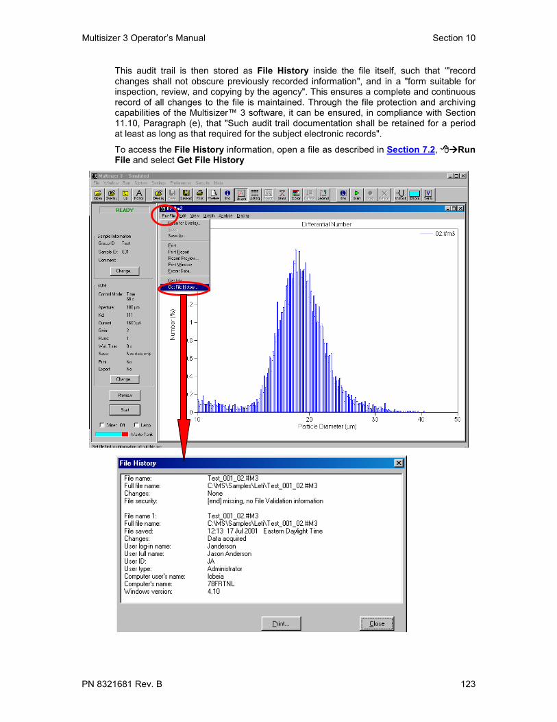
Multisizer 3 Operator’s Manual Section 10
PN 8321681 Rev. B 123
This audit trail is then stored as File History inside the file itself, such that ‘"recordchanges shall not obscure previously recorded information", and in a "form suitable forinspection, review, and copying by the agency". This ensures a complete and continuousrecord of all changes to the file is maintained. Through the file protection and archivingcapabilities of the Multisizer™ 3 software, it can be ensured, in compliance with Section11.10, Paragraph (e), that "Such audit trail documentation shall be retained for a periodat least as long as that required for the subject electronic records".
To access the File History information, open a file as described in Section 7.2, RunFile and select Get File History

Section 10 Multisizer 3 Operator’s Manual
124 PN 8321681 Rev. B
10.6.5 Setting Audit TrailIn addition to the auditing associated with the electronic file itself the Multisizer™ 3software offers two additional levels of auditing. First, a general system audits trail thatrecords and stores information at a system level, for example who logged in when, whenusers were added to the system etc. This is analogous to the security features of aWindows NT© operating system; this can be useful for systems using other operatingsystems. Second, the Multisizer™ 3 software generates an error log that stores andrecords errors associated with the system e.g. missing files, bad communications etc.
In the Administrator drop down menu select Audit Trail Settings.
.
Select the options in the dialog box and OK.
Note that the dialog has a button marked 21 CFR 11. When activated thisensures all options are set so that the settings meet with the rules asapplicable to 21 CFR part 11.

Multisizer 3 Operator’s Manual Section 10
PN 8321681 Rev. B 125
10.6.6 Assigning user privilegesThe level of access to the Multisizer™ 3 software system is controlled by the rightsgranted through the User Privileges dialog box. The operations granted through theseoptions are linked to the level of security chosen and to the "User Category" to which auser is assigned. Users can be classified into five different categories.
• Reviewer• Operator• Advanced Operator• Supervisor• Administrator
To access the User Privileges dialog box, in the Administrator drop-down menu selectUser Privileges. At this moment the access level to the software can be assigned to thedifferent categories of users.
If all the user accounts have not been created yet, at this moment they can be created,as well as the User Names and Passwords and the Audit Trial Settings. Thesesettings can be accessed using the three buttons located in the right lower part of theUser Privileges dialog box.
Select the options in the dialog box Set and then OK.
Note that the dialog has a button marked High Security 21 CFR 11. Whenactivated this ensures all options are set so that the settings meet with therules as applicable to 21 CFR part 11.

Section 10 Multisizer 3 Operator’s Manual
126 PN 8321681 Rev. B
10.6.7 Electronic SignatureIn Subpart A, Section 11.3, an electronic signature is defined as "a computer datacompilation of any symbol or series of symbols executed, adopted, or authorized by anindividual to be the legally binding equivalent of the individual’s handwritten signature".Subpart C, Section 11.100 of the regulation defines the general requirements of such amanifestation. Paragraph (a) states that "each electronic signature shall be unique to oneindividual and shall not be reused by, or reassigned to, anyone else". These twoparagraphs, taken together, mean that an electronic signature is some computerrepresentation of a user's identity, developed to insure the distinct and unique identity ofthat user. The procedural aspect of Section 11.100 requires that before any suchelectronic representation is applied, the organization first must "verify" the identity of thatindividual. The subsequent use of electronic signatures as the "legally binding equivalentof traditional handwritten signatures" then must be "certified" to the agency in writing
Subpart C, Section 11.200, refers to biometric and non-biometric forms of electronicsignature. Biometric signatures are defined in Subpart A, Section 11.3 as a "a method ofverifying an individual’s identity based on measurement of the individual’s physicalfeature(s) or repeatable action(s) where those features and/or actions are both unique tothat individual and measurable". Biometrics are generally regarded as techniques suchas fingerprints or retinal scans, which are considered to be totally unique to eachindividual and require specific forms of scanning devices to read and interpret. Non-biometric signatures are those that are computer generated and, as per Section 11.200,"Employ at least two distinct identification components such as an identification code andpassword". It is this form of electronic signature that is supported by the Multisizer™ 3software.
10.6.8 Generating electronic signaturesThe Multisizer™ 3 software employs User ID's and passwords to verify the identificationof each user logging into the system. When using this technique, Subpart C, Section11.300 of the regulation requires "maintaining the uniqueness of each combinedidentification code and password, such that no two individuals have the samecombination of identification code and password". This section also requires that the"identification code and password issuance’s are periodically checked, recalled, orrevised". Multisizer™ 3 software supports both of these provisions.
The administration of the system requires that individuals are added to the list of validMultisizer™ 3 users via the Add a User Account dialog screen. The "identification code"or username of each Multisizer™ 3 user must be unique. No two users on the sameMultisizer™ 3 system can have the same user name. It is also required that these userssupply a password to access the Multisizer™ 3 software, thus satisfying the requirementto "employ at least two distinct identification components such as an identification codeand password". Passwords can be controlled to prohibit the use of duplicates and toforce the selection of new passwords after a prescribed period of time.
By the implementation of these features, the Multisizer™ 3 software can satisfy therequirement that "identification code and password issuance’s are periodically checked,recalled, or revised".
Users may be authorized to generate electronic signatures by the administrator. Thisauthorization is granted in the User Privileges dialog box. When a user has beenauthorized, he can electronically sign a file. To generate the electronic signature, open afile as described in Section 7.2, Edit, and select Add Electronic Signature.

Multisizer 3 Operator’s Manual Section 10
PN 8321681 Rev. B 127
10.6.9 Applying electronic signaturesSubpart C, Section 11.200 stipulates several requirements for the control of electronicsignatures. Procedurally, the regulations require that electronic signatures "be used onlyby their genuine owners" and that they "be administered and executed to ensure thatattempted use of an individual’s electronic signature by anyone other than its genuineowner requires collaboration of two or more individuals". Through the application ofMultisizer™ 3 user and password configuration procedures, the system can beconfigured to "ensure" that inappropriate use of these identifiers can be performed onlyby the intentional divulgence of security information.
Section 11.200 further specifies the use of electronic signature components during aperiod "when an individual executes a series of signings during a single, continuousperiod of controlled system access", and "when an individual executes one or moresignings not performed during a single, continuous period of controlled system access".This section of the document represents the "heart" of electronic signature application. Tocomply with these provisions, the Multisizer™ 3 software uses the application of theusername and password to authenticate the user making and saving the changes, inconjunction with file history and audit trailing, "to independently record the date and timeof operator entries and actions that create, modify, or delete electronic records”.

Section 10 Multisizer 3 Operator’s Manual
128 PN 8321681 Rev. B
10.6.10 Additional security featuresThe Multisizer™ 3 software offers two important additional levels of security, that whilstnot specifically called for by the regulations, make defining and implementing systempolicies easier.Data Mirroring: The administrator has the option to securely store files in a separatelocation and in addition to that specified by a user. This is done by enabling the datamirroring option that can only be accessed under administrator mode.
File Attributes: Files can be protected to varying degrees using the file attribute options.
10.7 Starting the Multisizer 3 software with enabled security.After all settings for security have been configured, every time the Multisizer 3 softwareis started, the user is prompted to enter a user name and password. The software willautomatically configure according to the privileges granted to the user by theadministrator.
After using the Administrator, Supervisor and/or Advance Operator modes,in order to log off you must close down the Multisizer 3 program.
Back to TOC

Multisizer 3 Operator’s Manual Section 11
PN 8321681 Rev. B 129
SECTION 11 SPECIFICATIONS11.1 Dimensions and weight
Weight, Dimensions and Power (excluding computer)
Unpacked weight: 45 kg (99 lb)Width: 45 cm (18 in)Depth: 60 cm (24 in)Height: 60 cm (24 in)
Input Voltage within Set Ranges:
100 - 120 VAC; 230 - 240 VAC + 10%; single phase
Supply Frequency: 47 to 63 Hz inclusive
Power: Less than 55 volt-amps (watts)
Fuse types: 240 V, IEC (5x20 mm), Time delay (T), 3.15 A
The use of other fuse types may result in damage to the instrument.
11.2 Environmental Conditionsa) This instrument is safe for indoor use only.b) Installation category: 11.c) Pollution degree: 1.
Operating Temperature: 5°C to 40°C
Relative Humidity: 10% to 80% without condensation
Altitude: Up to 2000 m (5500 ft). Above 7300 m (20,000 ft)unpressurized transport may damage the monitor.
Electrolyte Solutions: All aqueous and non-aqueous electrolyte solutionsdevised for use with aperture technology will be suitablefor use with the Multisizer 3. Electrolytes should becompatible with glass, fluoropolymers, fluoroelastomers,and polypropylene.
Solvents unsuitable for use with silicone rubbers and silicone adhesivesare unlikely to be suitable for the Multisizer 3.
11.3 Operational ParametersParticle Size Range: 0.4µm to 1200µm in diameter.
0.0336fL to 904.8 x 10⁶ fL or µm3 in volume.The upper size limit is dictated by solution viscosity andparticle density, and the lower limit by the aperture size,electrolyte conductivity and environmental conditions.
Orifice Tube Sizes: 20 µm to 2000 µm apertures (nominal sizes). Each sizeallows the measurement of particles in a range of 2% to60% of aperture diameter.

Section 11 PN 8321681 Rev. A
130 PN 8321681 Rev. B
Aperture(µm)
Range(µm)
Range(fL or µm3)
20 0.4 – 12 0.0336 - 90530 0.6 – 18 0.113 – 305450 1.0 – 30 0.524 – 1414070 1.4 – 42 1.440 – 38800100 2.0 – 60 4.189 – 113130140 2.8 – 84 11.49 – 310330200 4.0 – 120 33.5 – 904830280 5.6 – 168 92.05 – 2.483x10⁶
400 8.0 – 240 268 – 7.238 x10⁶
560 11.2 – 336 735.6 – 19.86 x10⁶
1000 20 – 600 4189 – 113.1 x10⁶
2000 40 - 1200 33540 – 904.8 x10⁶
Number of Channels: Pulse data is digitized and can be processed to achieveup to 300 size channels for any sleeted range. Thenumber of channels and range can be reprocessed asnecessary.
Digital Pulse Processor: High-speed digitalization of the signal allows the use ofpulse area analysis and other techniques for additionalparticle characterization. This information may be usedat a later time to recalculate the size distribution usingdifferent parameters.
Pulse Data: Up to 525,000 pulses per analysis.
Linearity: ± 1 % for diameter
± 3 % for volume.
Aperture Current Range: 30 µA – 6000 µA in 0.2 µA steps
Aperture Current Accuracy: ± 0.4% of setting
Polarity error: Less than 0.5%
Time mode range: 0.01 to 1000 seconds, selectable in 10 ms increments
Metering System: Mercury-free wide range metering pump
Metered Sample Volumes:(Volumetric mode only) Continuously selectable from 50µl to 2000µl
Volumetric pump accuracy: Better than 99.5%
11.4 Regulatory ComplianceThe software is 21 CFR part 11 compliant
Back to TOC

Multisizer 3 Operator’s Manual INDEX
PN 8321681 Rev. B 131
2
21 CFR Part 11, 118
A
ACCUVETTE®, 21, 31, 37Administrator Mode, 120, 121, 124, 125Analysis Report, 48Analysis Settings, 40Analytical volume, 52Aperture, 1, 2, 3, 4, 5, 6, 7, 18, 20, 21, 22,
23, 24, 26, 29, 30, 31, 35, 36, 37, 40, 44,46, 50, 58, 76, 98, 99, 100, 129
Aperture currentExcessive, 7
Aperture ListEdit, 35
Aperture Tube, 5, 21, 22, 23, 35Aperture Tube
Changing. See Removing Aperture TubeRemoving, 23
Aperture Tube, 18, 19, 21, 22, 26, 35, 46Fitting, 21Installing, 24Setting Up, 22
Aperture Viewer, 18, 30Apertures
Damaged, 7As Accumulated, 104Audit Trail, 122, 124
Setting, 124Average, 68, 69, 70
B
Background, 55, 56, 57, 81, 82Running, 55Subtracting, 56
Between Cursors, 98, 99, 100Bin Spacing, 50
C
Calibration, 6, 29, 33, 34, 38Verification, 29
Calibration constant, 6Calibrator, 31, 33, 39
Choosing, 31Running, 33
Cautions, 5, 6Chemical, 6Electrical, 6
Cells, 28, 44, 104Change Aperture Wizard, 23, 35
Channels, 2, 4, 40, 50, 86, 98, 99, 130Cleaning, 58Compare Statistics, 84Concentration Index Bar, 32, 38Connect to Multisizer 3, 14, 17Connections, 9Control Mode, 41, 42
Manual, 41Modal Count, 41Selecting, 42Time, 41Total Count, 41Volumetric, 41
Control Program, 14Control Sample, 53, 54, 84Convert Pulses to Size, 2, 49Coulter Principle, 1, 2.Current and gain, 28, 43, 44, 46Current and Gain, 28
Setting, 28Custom logo, 107
D
Data Export, 106Data Mirroring, 128Default Preferences, 80, 110Demodata, 61, 80Density, 53Destination Directory, 48Diameter, 50, 104Digital Pulse Processing, 2Dilution Factor, 54Disconnect from Multisizer 3, 15Dispersant agent, 45Distribution, 42, 95
Cumulative <, 97Differential, 95Types, 95
Distribution Types, 95
E
Electrical interference, 7Electrical Sensing Zone, 1, 2Electrode, 18, 20Electrolyte, 5, 6, 7, 9, 11, 21, 25, 26, 31, 35,
37, 40, 44, 45, 46, 52, 55, 58, 59, 129Electrolyte
Selecting, 26Electrolyte Volume, 52, 81Electronic Records, 118Electronic Signature
Generating, 126Applying, 127

INDEX PN 8321681 Rev. A
132 PN 8321681 Rev. B
Electronic Signatures, 118Enter Sample Info, 51, 53Equivalent Spherical Diameter, 2, 53ESZ. See Electrical Sensing ZoneExporting Data, 47
F
FDA, 118File
Opening, 60File Attributes, 128File History, 122, 123
Getting, 123File Name, 47, 53
Generating, 47Flushing, 46Fonts, 107Frontal Panel, 18
G
Graph Options, 106
I
Installation, 8Instrument Controls, 15International Standard ISO 13319, 2Interpolation Points, 86
K
Kd, 6, 34, 35, 81
L
Language, 109Linear X axis, 97Location, 8Logarithmic X axis, 97Login, 122
M
Main Menu Bar, 14, 17, 23, 33, 35, 38Mass, 3, 52, 53, 95Metering pump, 58Metering Pump, 27
Adjusting, 27Modal value, 31, 33, 39Multiple runs, 42Multisizer II Edit, 50Multi-Tube Overlap, 76, 77
N
Noise Level, 29, 43Measuring, 29
O
Operational checks, 122Optics, 30
Aligning, 30Overlay, 63, 64, 65, 66, 67
Open, 65, 67Save, 66
Overlaying Files, 63
P
Page Setup, 107Particle Concentration, 42, 58
Using Large Apertures, 58Particle Size, 1, 2, 76Preferences, 80, 94, 101, 102, 103, 105,
106, 107, 108, 109, 110, 111, 114, 115Costumizing, 94Saving, 109
Preferences File, 80, 114Preferences Menu, 80Preview, 32, 37, 57Prferences, 80. MenuPrinted. SeePrinted Report, 85, 86Printer, 93Printing, 48, 93Pulse, 1, 2, 46, 89, 90, 94, 102, 103, 104,
118, 130Pulse Graph, 103Pulse Listing, 103Pulses, 2, 49, 89, 102Pulses Graph, 89
R
Regulatory Compliance, 118Report, 3, 9, 48, 80, 82, 83, 85, 86, 87, 88,
89, 90, 91, 92, 93Report, 80, 111
Printing, 80Results, 60
Saving, 60Viewing, 60
Reviewer, 125

Multisizer 3 Operator’s Manual INDEX
PN 8321681 Rev. B 133
S
Sample, 7, 18, 25, 51, 52, 53, 54, 57, 81, 82,84, 85, 98. InfoRunning, 57
Sample Analysis, 40Sample Compartment, 18, 25Sample Dispersion, 7Sample Info
Short, 82Standard, 81
Sample Information, 51Entering, 51
Sample Platform, 18Sample Statistics, 54, 84, 85Sample volume, 52Saving, 46, 50, 80, 109, 111, 115Security, 14, 15, 119, 120, 125
Setting Up, 119Security Level, 14, 120Settings, 41, 49, 50, 51, 56, 57, 109, 111,
116, 117Shape Factor, 53Shutting down the Multisizer 3, 17Size Bins, 50Size classes, 2, 4, 86, 100Size distribution, 2, 3, 4, 42, 50, 53, 76, 78,
82, 85, 88Size Graph, 82, 94, 95, 98Size Interpolation, 86, 94, 100Size Listing, 85, 86, 94, 98Size Statistics, 83, 88, 94, 99Size Trend, 72, 73, 74, 105
Creating, 72SOM. See Standard Operating MethodSOP. See Standard Operating ProcedureSpecific Surface Area, 104Specifications, 129Standard Operating Method, 41, 47, 49, 50,
51, 111Changing, 41Saving, 50
Standard Operating Procedure, 51, 109,112, 114Saving, 114
Standard Operating ProceduresCreating, 111
Standard Operation Procedure, 50, 80Statistics, 83, 84, 85, 99
Status Panel, 16, 32, 37, 41, 55, 57Stirrer, 18, 19, 20Stirrer Rotation Control, 18Stirrer Speed Control, 18System, 27, 51, 58, 59
Cleaning, 58
T
Threshold, 42, 43, 50Toolbar, 108Trap, 19Trend, 72, 73, 74, 75, 91, 92, 94, 101, 102,Trend Graph, 91, 94, 101Trend Listing, 92, 94, 102
U
User Account, 120, 121, 126Adding, 120
User Names and Passwords, 121, 122Selcting, 121
User Privileges, 125Assigning, 125Granting, 125
V
Verfication. See CalibrationView Options, 103Voltage, 1, 4, 6, 11, 12, 13Volume, 58, 88, 104
W
Warnings, 5Chemical, 5Electrical, 5Fire, 5Mechanical, 5
Windows Colors, 108
X
X Axis, 97Scale, 97
X-Axis, 104