section 033000 - cast-in-place concrete …barrierone.com/admin/assets/upload/bfcaba5ae886da... ·...
TRANSCRIPT

Copyright 2017 AIA MasterSpec Premium 06/17
CAST-IN-PLACE CONCRETE 033000 - 1
SECTION 033000 - CAST-IN-PLACE CONCRETE
This Product MasterSpec Section modifies the original MasterSpec text.
Revisions made to the original MasterSpec text are made solely by Concrete Moisture Solutions and are not endorsed by, or representative of the opinions of the American Institute of Architects (AIA). AIA is not liable in any way for such revisions or for the use of this Product MasterSpec Section by any end user. A qualified design professional should review and edit the document to suit project requirements.
For more information, contact Concrete Moisture Solutions, Inc. at (877) 224-5850 or go to www.barrierone.com.
For information about MasterSpec visit www.MasterSpec.com.
TIPS:
Those sections highlighted in yellow are intended as “cut and paste” information for the overall specifica-tion section 033000 if the designer chooses not to use stand-alone section 03 05 10 as provided at www.barrierone.com. The entirety of the spec format is included so designers can navigate where to in-sert information required for Barrier One Porosity Inhibiting Admixture (“PIA”) dosage and warrantabil-ity.
Those sections highlighted in yellow and “struck though” is information already in the spec format which is incompatible with Barrier One “PIA” dosed concrete and should be deleted unless used for concrete not dosed with Barrier One “PIA”.
PART 1 - GENERAL
1.1 RELATED DOCUMENTS
A. Drawings and general provisions of the Contract, including General and Supplementary Conditions and Division 01 Specification Sections, apply to this Section.
1.2 SUMMARY
A. Section includes cast-in-place concrete, including formwork, reinforcement, concrete materials, mixture design, placement procedures, and finishes.
B. Related Requirements:
1. Section 033300 "Architectural Concrete" for general building applications of specially finished formed concrete.
2. Section 035300 "Concrete Topping" for emery- and iron-aggregate concrete floor toppings.
Copyright 2017 AIA MasterSpec Premium 06/17
CAST-IN-PLACE CONCRETE 033000 - 2
3. Section 312000 "Earth Moving" for drainage fill under slabs-on-grade. 4. Section 321313 "Concrete Paving" for concrete pavement and walks. 5. Section 321316 "Decorative Concrete Paving" for decorative concrete pavement and
walks.
1.3 DEFINITIONS
A. Cementitious Materials: Portland cement alone or in combination with one or more of the following: blended hydraulic cement, fly ash, slag cement, other pozzolans, and silica fume; materials subject to compliance with requirements.
B. W/C Ratio: The ratio by weight of water to cementitious materials.
1.4 PREINSTALLATION MEETINGS
A. Preinstallation Conference: Conduct conference at [Project site] <Insert location>.
1. Before submitting design mixtures, review concrete design mixture and examine procedures for ensuring quality of concrete materials. Verify all parties review “PIA” project quality control procedures, concrete mix designs and procedures for ensuring quality of concrete materials. Require representatives of each entity directly concerned with cast-in-place concrete to attend, (in person, conference call, or to provide electronic review of documents), including the following:
a. Contractor's superintendent. b. Independent testing agency responsible for concrete design mixtures. c. Ready-mix concrete manufacturer. d. Concrete Subcontractor. e. Special concrete finish Subcontractor. f. PIA manufacturer.
2. Review [special inspection and testing and inspecting agency procedures for field quality control,] [concrete finishes and finishing,] [cold- and hot-weather concreting procedures,] [curing procedures,] [construction contraction and isolation joints, and joint-filler strips,] [semirigid joint fillers,] [forms and form removal limitations,] [shoring and reshoring procedures,] [vapor-retarder installation,] [anchor rod and anchorage device installation tolerances,] [steel reinforcement installation,] [methods for achieving specified floor and slab flatness and levelness] [floor and slab flatness and levelness measurement,] [concrete repair procedures,] and concrete protection.
1.5 ACTION SUBMITTALS
A. Product Data: For each type of product.
B. Sustainable Design Submittals:

Copyright 2017 AIA MasterSpec Premium 06/17
CAST-IN-PLACE CONCRETE 033000 - 3
1. <Double click to insert sustainable design text for recycled content.> 2. <Double click to insert sustainable design text for regional materials.> 3. <Double click to insert sustainable design text for liquid floor treatments and curing and
sealing compounds.>
C. Design Mixtures: For each concrete mixture. Submit alternate design mixtures when characteristics of materials, Project conditions, weather, test results, or other circumstances warrant adjustments.
1. Indicate amounts of mixing water to be withheld for later addition at Project site.
D. Steel Reinforcement Shop Drawings: Placing Drawings that detail fabrication, bending, and placement. Include bar sizes, lengths, material, grade, bar schedules, stirrup spacing, bent bar diagrams, bar arrangement, splices and laps, mechanical connections, tie spacing, hoop spacing, and supports for concrete reinforcement.
E. Construction Joint Layout: Indicate proposed construction joints required to construct the structure.
1. Location of construction joints is subject to approval of the Architect.
F. Samples: For [waterstops] [vapor retarder] <Insert products>. 1. For ASTM E 1745 – 17 compliant vapor retarder minimum Class A, B or C, minimum
thickness 6 mil, conforming to Table 1. 2. Porosity Inhibiting Admixture (PIA):
a. Product Data: Manufacturer’s printed data. b. Independent product test reports performed by a qualified testing agency
evidencing compliance and/or certification with the US Army Corps of Engineers. c. Sample copy of copyrighted “Life of the Concrete” warranty. d. Sample copy of copyrighted Adhesion Guarantee. e. Sample copy of copyrighted Moisture Letter. f. HPD Health Product Declaration (Independently verified). g. Safety Data Sheet. (SDS) h. Provide copy of USA based insurance coverage to confirm warranty enforcement
and legitimacy upon request. i. National reference list of 2800+ standard “Life of the Concrete” warranted
projects; all of which had ASTM 5084 testing and/or Army Corps of Engineers CRD C48-92 performed.
1.6 INFORMATIONAL SUBMITTALS
A. Qualification Data: For [Installer] [manufacturer] [testing agency].
B. Welding certificates.
C. Material Certificates: For each of the following, signed by manufacturers:
1. Cementitious materials. 2. Admixtures. 3. Form materials and form-release agents.

Copyright 2017 AIA MasterSpec Premium 06/17
CAST-IN-PLACE CONCRETE 033000 - 4
4. Steel reinforcement and accessories. 5. Fiber reinforcement. 6. Waterstops. 7. Curing compounds. 8. Floor and slab treatments. 9. Bonding agents. 10. Adhesives. 11. Vapor retarders. 12. Semirigid joint filler. 13. Joint-filler strips. 14. Repair materials.
D. Material Test Reports: For the following, from a qualified testing agency:
1. Aggregates[: Include service record data indicating absence of deleterious expansion of concrete due to alkali aggregate reactivity].
E. Formwork Shop Drawings: Prepared by or under the supervision of a qualified professional engineer, detailing fabrication, assembly, and support of formwork.
1. Shoring and Reshoring: Indicate proposed schedule and sequence of stripping formwork, shoring removal, and reshoring installation and removal.
F. Floor surface flatness and levelness measurements indicating compliance with specified tolerances.
G. Field quality-control reports.
H. Minutes of preinstallation conference.
1.7 QUALITY ASSURANCE
A. Installer Qualifications: A qualified installer who employs on Project personnel qualified as ACI-certified Flatwork Technician and Finisher and a supervisor who is an ACI-certified Concrete Flatwork Technician.
B. Manufacturer Qualifications: A firm experienced in manufacturing ready-mixed concrete products and that complies with ASTM C 94/C 94M requirements for production facilities and equipment.
1. Manufacturer certified according to NRMCA's "Certification of Ready Mixed Concrete Production Facilities."
2. Porosity Inhibiting Admixture Manufacturer Qualifications: A manufacturer with not less than Ten (10) years’ experience in the actual manufacturing of concrete enhancement technology admixtures. Selected product manufacturer must have certification of compliance with ASTM C494 /C494M testing protocols from an independent AASHTO / Corps of Engineers approved laboratory. A manufactured product is a stand-alone source or entity that manufacturers the porosity inhibiting admixture “PIA” and its components primarily in house. Manufacturer must have legitimate USA manufacturing presence to

Copyright 2017 AIA MasterSpec Premium 06/17
CAST-IN-PLACE CONCRETE 033000 - 5
assure legitimate warranty enforcement. Manufacturer will provide an on-site, contracted independent ACI certified technical representative capable of randomly sampling each day’s placement. One random cylinder per day’s concrete placement should be independently tested per ASTM 5084 and / or Army Corp of Engineers CRD C48-92 testing criteria.
3. Porosity Inhibiting Admixture (“PIA”) Warranty Requirements:
a. “PIA” must be installed according to, and in compliance with, the manufacturer’s published data sheet, including: 1) Dosing instructions. 2) Onsite independent representation and sampling requirements. 3) Use of an ASTM E 1745 vapor retarder installed following ASTM E 1643
and ACI 303.2R -06 and ASTM F710 guidelines; elevated slabs to receive flooring do not require a vapor retarder.
4) The design and specifications for roof deck assemblies, to include but not limited to, the use of air barriers and/or vapor retarders is the sole responsibility of the design professional and is excluded from this warranty as are any costs incurred due to roofing overburden.
5) Curing for all moisture sensitive products should be in compliance with ACI 308-16 “Guide to External Curing of Concrete” Section 4.1.4 “Moisture Sensitive Floors”
b. “PIA” Manufacturer's Standard Warranty shall include: 1) Term: Life of the Concrete Warranty. 2) Repair and/or removal of failed flooring or roofing. 3) Placement of a topical moisture remediation system. 4) Replacement of flooring/roofing materials like original installed to include
material and labor. 5) Sodium Silicate Free Concrete Enhancement Technology (CET) known as a
Porosity Inhibiting Admixture “PIA” c. Manufacturer’s Adhesion Warranty shall include:
1) Warranty term to match that of the adhesive and/or primer manufacturer's material defect warranty.
2) Issued upon “PIA” manufacturer’s acceptance of field adhesive bond testing which followed flooring / adhesive manufacturer guidelines and requirements noted in ASTM F-710 for installation on a nonporous surface.
d. Moisture Letter: “PIA” Manufacturer shall provide a standard moisture letter indicating warrantability up to 100% RH per qualified ASTM 2170 Insitu Probe testing and up 25lbs for ASTM 1869 CaCl testing.
C. ‘PIA” DELIVERY, STORAGE, AND HANDLING 1. Deliver “PIA” in manufacturer’s original, undamaged containers. 2. Store “PIA” protected from exposure to harmful weather conditions and in a temperature-
controlled area above 36 degrees. 3. Do not allow product to freeze. Should product freeze, immediately contact the “PIA”
manufacturer for further instructions.

Copyright 2017 AIA MasterSpec Premium 06/17
CAST-IN-PLACE CONCRETE 033000 - 6
D. Testing Agency Qualifications: An independent agency, [ acceptable to authorities having jurisdiction,] qualified according to ASTM C 1077 and ASTM E 329 for testing indicated.
1. Personnel conducting field tests shall be qualified as ACI Concrete Field Testing Technician, Grade 1, according to ACI CP-1 or an equivalent certification program.
2. Personnel performing laboratory tests shall be ACI-certified Concrete Strength Testing Technician and Concrete Laboratory Testing Technician, Grade I. Testing agency laboratory supervisor shall be an ACI-certified Concrete Laboratory Testing Technician, Grade II.
3. Porosity Inhibiting Admixture Collection Agent / Representative Qualifications: a. Daily sample collections shall be taken by an ACI Concrete Field Testing
Technician, Grade 1, or equivalent, on behalf and at cost of the PIA manufacturer. b. Slab Moisture Testing and Evaluation: Personnel performing laboratory tests shall
be certified in the conduct of ASTM D5084 and/or Army Corp of Engineers CRD C48-92 under the supervision of a licensed geotechnical engineer. The determination as to whether the concrete slab is prepared to receive flooring, coatings, roofing, etc. rests with the “PIA” manufacturer in conjunction with adherence and compliance with manufacture’s installation guidelines.
E. Welding Qualifications: Qualify procedures and personnel according to AWS D1.4/D 1.4M.
F. Mockups: Cast concrete [slab-on-grade] [and] [formed-surface] panels to demonstrate typical joints, surface finish, texture, tolerances, floor treatments, and standard of workmanship.
1. Build panel approximately [200 sq. ft. (18.6 sq. m) for slab-on-grade] [and] [100 sq. ft. (9.3 sq. m) for formed surface] <Insert area> in the location indicated or, if not indicated, as directed by Architect.
2. Subject to compliance with requirements, approved mockups may become part of the completed Work if undisturbed at time of Substantial Completion.
1.8 PRECONSTRUCTION TESTING
A. Preconstruction Testing Service: Engage a qualified testing agency to perform preconstruction testing on concrete mixtures.
1.9 DELIVERY, STORAGE, AND HANDLING
A. Steel Reinforcement: Deliver, store, and handle steel reinforcement to prevent bending and damage.[ Avoid damaging coatings on steel reinforcement.]
B. Waterstops: Store waterstops under cover to protect from moisture, sunlight, dirt, oil, and other contaminants.
1.10 FIELD CONDITIONS
A. Cold-Weather Placement: Comply with ACI 306.1 and as follows. Protect concrete work from physical damage or reduced strength that could be caused by frost, freezing actions, or low temperatures.

Copyright 2017 AIA MasterSpec Premium 06/17
CAST-IN-PLACE CONCRETE 033000 - 7
1. When average high and low temperature is expected to fall below 40 deg F (4.4 deg C) for three successive days, maintain delivered concrete mixture temperature within the temperature range required by ACI 301 (ACI 301M).
2. Do not use frozen materials or materials containing ice or snow. Do not place concrete on frozen subgrade or on subgrade containing frozen materials.
3. Do not use calcium chloride, salt, or other materials containing antifreeze agents or chemical accelerators unless otherwise specified and approved in mixture designs.
B. Hot-Weather Placement: Comply with ACI 301 (ACI 301M) and ACI 305.1 (ACI 305.1M), and as follows:
1. Maintain concrete temperature below 90 deg F (32 deg C) at time of placement. Chilled mixing water or chopped ice may be used to control temperature, provided water equivalent of ice is calculated to total amount of mixing water. Using liquid nitrogen to cool concrete is Contractor's option.
2. Fog-spray forms, steel reinforcement, and subgrade just before placing concrete. Keep subgrade uniformly moist without standing water, soft spots, or dry areas.
PART 2 - PRODUCTS
2.1 CONCRETE, GENERAL
A. ACI Publications: Comply with the following unless modified by requirements in the Contract Documents:
1. ACI 301 (ACI 301M). 2. ACI 117 (ACI 117M).
B. ACI Publications: For slabs to receive moisture sensitive coatings or material, comply with the following unless modified by requirements in the Contract Documents: 1. ACI 302.2R-06, "Guide for Concrete Slabs that Receive Moisture-Sensitive Flooring". 2. ACI 308-16 “Guide to External Curing of Concrete” Ref. Section 4.1.4 “Moisture
Sensitive Floors”
2.2 FORM-FACING MATERIALS
A. Smooth-Formed Finished Concrete: Form-facing panels that provide continuous, true, and smooth concrete surfaces. Furnish in largest practicable sizes to minimize number of joints.
1. Plywood, metal, or other approved panel materials. 2. Exterior-grade plywood panels, suitable for concrete forms, complying with DOC PS 1,
and as follows:
a. High-density overlay, Class 1 or better. b. Medium-density overlay, Class 1 or better; mill-release agent treated and edge
sealed. c. Structural 1, B-B or better; mill oiled and edge sealed. d. B-B (Concrete Form), Class 1 or better; mill oiled and edge sealed.
Copyright 2017 AIA MasterSpec Premium 06/17
CAST-IN-PLACE CONCRETE 033000 - 8
3. Overlaid Finnish birch plywood.
B. Rough-Formed Finished Concrete: Plywood, lumber, metal, or another approved material. Provide lumber dressed on at least two edges and one side for tight fit.
C. Forms for Cylindrical Columns, Pedestals, and Supports: Metal, glass-fiber-reinforced plastic, paper, or fiber tubes that produce surfaces with gradual or abrupt irregularities not exceeding specified formwork surface class. Provide units with sufficient wall thickness to resist plastic concrete loads without detrimental deformation.
D. Pan-Type Forms: Glass-fiber-reinforced plastic or formed steel, stiffened to resist plastic concrete loads without detrimental deformation.
E. Void Forms: Biodegradable paper surface, treated for moisture resistance, structurally sufficient to support weight of plastic concrete and other superimposed loads.
F. Chamfer Strips: Wood, metal, PVC, or rubber strips, 3/4 by 3/4 inch (19 by 19 mm), minimum.
G. Rustication Strips: Wood, metal, PVC, or rubber strips, kerfed for ease of form removal.
H. Form-Release Agent: Commercially formulated form-release agent that does not bond with, stain, or adversely affect concrete surfaces and does not impair subsequent treatments of concrete surfaces.
1. Formulate form-release agent with rust inhibitor for steel form-facing materials.
I. Form Ties: Factory-fabricated, removable or snap-off glass-fiber-reinforced plastic or metal form ties designed to resist lateral pressure of fresh concrete on forms and to prevent spalling of concrete on removal.
1. Furnish units that leave no corrodible metal closer than 1 inch (25 mm) to the plane of exposed concrete surface.
2. Furnish ties that, when removed, leave holes no larger than 1 inch (25 mm) in diameter in concrete surface.
3. Furnish ties with integral water-barrier plates to walls indicated to receive dampproofing or waterproofing.
2.3 STEEL REINFORCEMENT
A. <Double click to insert sustainable design text for recycled content of steel products.>
B. Reinforcing Bars: ASTM A 615/A 615M, Grade 60 (Grade 420), deformed.
C. Low-Alloy-Steel Reinforcing Bars: ASTM A 706/A 706M, deformed.
D. Galvanized Reinforcing Bars: [ASTM A 615/A 615M, Grade 60 (Grade 420)] [ASTM A 706/A 706M], deformed bars, ASTM A 767/A 767M, [Class I] [Class II] zinc coated after fabrication and bending.
E. Epoxy-Coated Reinforcing Bars: [ASTM A 615/A 615M, Grade 60 (Grade 420)] [ASTM A 706/A 706M], deformed bars, [ASTM A 775/A 775M] [or]
Copyright 2017 AIA MasterSpec Premium 06/17
CAST-IN-PLACE CONCRETE 033000 - 9
[ASTM A 934/A 934M], epoxy coated, with less than 2 percent damaged coating in each 12-inch (300-mm) bar length.
F. Stainless-Steel Reinforcing Bars: ASTM A 955/A 955M, Grade 60 (Grade 420), [Type 304] [Type 316L], deformed.
G. Steel Bar Mats: ASTM A 184/A 184M, fabricated from [ASTM A 615/A 615M, Grade 60 (Grade 420)] [ASTM A 706/A 706M], deformed bars, assembled with clips.
H. Plain-Steel Wire: ASTM A 1064/A 1064M, [as drawn] [galvanized].
I. Deformed-Steel Wire: ASTM A 1064/A 1064M.
J. Epoxy-Coated Wire: ASTM A 884/A 884M, Class A, Type 1 coated, [as-drawn, plain] [deformed]-steel wire, with less than 2 percent damaged coating in each 12-inch (300-mm) wire length.
K. Plain-Steel Welded-Wire Reinforcement: ASTM A 1064/A 1064M, plain, fabricated from as-drawn steel wire into flat sheets.
L. Deformed-Steel Welded-Wire Reinforcement: ASTM A 1064/A 1064M, flat sheet.
M. Galvanized-Steel Welded-Wire Reinforcement: ASTM A 1064/A 1064M, plain, fabricated from galvanized-steel wire into flat sheets.
N. Epoxy-Coated Welded-Wire Reinforcement: ASTM A 884/A 884M, Class A coated, Type 1, [plain] [deformed] steel.
2.4 REINFORCEMENT ACCESSORIES
A. Joint Dowel Bars: ASTM A 615/A 615M, Grade 60 (Grade 420), plain-steel bars, cut true to length with ends square and free of burrs.
B. Epoxy-Coated Joint Dowel Bars: ASTM A 615/A 615M, Grade 60 (Grade 420), plain-steel bars, ASTM A 775/A 775M epoxy coated.
C. Epoxy Repair Coating: Liquid, two-part, epoxy repair coating; compatible with epoxy coating on reinforcement and complying with ASTM A 775/A 775M.
D. Zinc Repair Material: ASTM A 780/A 780M.
E. Bar Supports: Bolsters, chairs, spacers, and other devices for spacing, supporting, and fastening reinforcing bars and welded-wire reinforcement in place. Manufacture bar supports from steel wire, plastic, or precast concrete according to CRSI's "Manual of Standard Practice," of greater compressive strength than concrete and as follows:
1. For concrete surfaces exposed to view, where legs of wire bar supports contact forms, use CRSI Class 1 plastic-protected steel wire or CRSI Class 2 stainless-steel bar supports.
2. For epoxy-coated reinforcement, use epoxy-coated or other dielectric-polymer-coated wire bar supports.

Copyright 2017 AIA MasterSpec Premium 06/17
CAST-IN-PLACE CONCRETE 033000 - 10
3. For zinc-coated reinforcement, use galvanized wire or dielectric-polymer-coated wire bar supports.
2.5 CONCRETE MATERIALS
A. <Double click to insert sustainable design text for regional materials (concrete).>
B. Source Limitations: Obtain each type or class of cementitious material of the same brand from the same manufacturer's plant, obtain aggregate from single source, and obtain admixtures from single source from single manufacturer.
C. Cementitious Materials:
1. Portland Cement: ASTM C 150/C 150M, [Type I] [Type II] [Type I/II] [Type III] [Type V], [gray] [white].
2. Fly Ash: ASTM C 618, [Class F] [Class F or C]. 3. Slag Cement: ASTM C 989/C 989M, Grade 100 or 120. 4. Blended Hydraulic Cement: ASTM C 595/C 595M, [Type IS, portland blast-furnace
slag] [Type IP, portland-pozzolan] [Type IL, portland-limestone] [Type IT, ternary blended] cement.
5. Silica Fume: ASTM C 1240, amorphous silica.
D. Normal-Weight Aggregates: ASTM C 33/C 33M, [Class 3S] [Class 3M] [Class 1N] <Insert class> coarse aggregate or better, graded. Provide aggregates from a single source[ with documented service record data of at least 10 years' satisfactory service in similar applications and service conditions using similar aggregates and cementitious materials].
1. Maximum Coarse-Aggregate Size: [1-1/2 inches (38 mm)] [1 inch (25 mm)] [3/4 inch (19 mm)] <Insert dimension> nominal.
2. Fine Aggregate: Free of materials with deleterious reactivity to alkali in cement.
E. Lightweight Aggregate: ASTM C 330/C 330M, [1-inch (25-mm)] [3/4-inch (19-mm)] [1/2-inch (13-mm)] [3/8-inch (10-mm)] nominal maximum aggregate size.
F. Air-Entraining Admixture: ASTM C 260/C 260M.
G. Chemical Admixtures: Certified by manufacturer to be compatible with other admixtures and that do not contribute water-soluble chloride ions exceeding those permitted in hardened concrete. Do not use calcium chloride or admixtures containing calcium chloride.
1. Water-Reducing Admixture: ASTM C 494/C 494M, Type A. 2. Retarding Admixture: ASTM C 494/C 494M, Type B. 3. Water-Reducing and Retarding Admixture: ASTM C 494/C 494M, Type D. 4. High-Range, Water-Reducing Admixture: ASTM C 494/C 494M, Type F. 5. High-Range, Water-Reducing and Retarding Admixture: ASTM C 494/C 494M, Type G. 6. Plasticizing and Retarding Admixture: ASTM C 1017/C 1017M, Type II. 7. Porosity Inhibiting Admixture: ASTM C494 /C494M
H. Set-Accelerating Corrosion-Inhibiting Admixture: Commercially formulated, anodic inhibitor or mixed cathodic and anodic inhibitor; capable of forming a protective barrier and minimizing
Copyright 2017 AIA MasterSpec Premium 06/17
CAST-IN-PLACE CONCRETE 033000 - 11
chloride reactions with steel reinforcement in concrete and complying with ASTM C 494/C 494M, Type C.
1. <Double click here to find, evaluate, and insert list of manufacturers and products.>
I. Non-Set-Accelerating Corrosion-Inhibiting Admixture: Commercially formulated, non-set-accelerating, anodic inhibitor or mixed cathodic and anodic inhibitor; capable of forming a protective barrier and minimizing chloride reactions with steel reinforcement in concrete.
1. <Double click here to find, evaluate, and insert list of manufacturers and products.>
J. Color Pigment: ASTM C 979/C 979M, synthetic mineral-oxide pigments or colored water-reducing admixtures; color stable,[ free of carbon black,] nonfading, and resistant to lime and other alkalis.
1. <Double click here to find, evaluate, and insert list of manufacturers and products.> 2. Color: [As indicated by manufacturer's designation] [Match Architect's sample] [As
selected by Architect from manufacturer's full range].
K. Water: ASTM C 94/C 94M[ and potable].
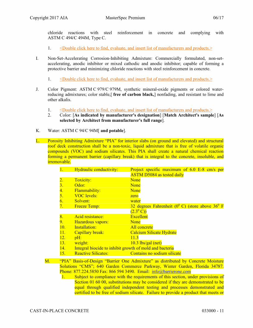
L. Porosity Inhibiting Admixture “PIA” for interior slabs (on ground and elevated) and structural roof deck construction shall be a non-toxic, liquid admixture that is free of volatile organic compounds (VOC) and sodium silicates. This PIA shall create a natural chemical reaction forming a permanent barrier (capillary break) that is integral to the concrete, insoluble, and irremovable.
1. Hydraulic conductivity: Project specific maximum of 6.0 E-8 cm/s per ASTM D5084 as tested daily
2. Toxicity: None 3. Odor: None 4. Flammability: None 5. VOC levels: zero 6. Solvent: water 7. Freeze Temp: 32 degrees Fahrenheit (00 C) (store above 360 F
(2.30 C)) 8. Acid resistance: Excellent 9. Hazardous vapors: None 10. Installation: All concrete 11. Capillary break: Calcium Silicate Hydrate 12. pH: 11.3 13. weight: 10.3 lbs/gal (net) 14. Integral biocide to inhibit growth of mold and bacteria 15. Reactive Silicates: Contains no sodium silicate
M. “PIA” Basis-of-Design “Barrier One Admixture” as distributed by Concrete Moisture Solutions “CMS”; 640 Garden Commerce Parkway, Winter Garden, Florida 34787. Phone: 877.224.5850 Fax: 866 594 3490. Email: [email protected] 1. Subject to compliance with the requirements of this section, under provisions of
Section 01 60 00, substitutions may be considered if they are demonstrated to be equal through qualified independent testing and processes demonstrated and certified to be free of sodium silicate. Failure to provide a product that meets or
Copyright 2017 AIA MasterSpec Premium 06/17
CAST-IN-PLACE CONCRETE 033000 - 12
exceeds the “PIA’s” minimum warranty requirements of Part I and the “PIA” field quality control requirements of Part 3 will result in all subsequent testing and slab remediation costs being borne by the Ready-Mix supplier, Concrete Contractor and General Contractor. Sodium Silicate MVRAs are not to be considered as equal to the newest concrete enhancement technologies known as porosity inhibiting admixtures or “PIA”. The responsibility and issuance of warranties for such a substitution will be borne by the project field parties submitting such a substitution.
2.6 FIBER REINFORCEMENT
A. Carbon-Steel Fiber: ASTM A 820/A 820M, Type 1, cold-drawn wire, deformed, minimum of [1.5 inches (38 mm)] [2 inches (50 mm)] [2.4 inches (60 mm)] <Insert dimension> long, and aspect ratio of [35 to 40] [45 to 50] [60 to 65] <Insert ratio>.
1. <Double click here to find, evaluate, and insert list of manufacturers and products.>
B. Carbon-Steel Fiber: ASTM A 820/A 820M, Type 2, cut sheet, deformed, minimum of [1.5 inches (38 mm)] [2 inches (50 mm)] [2.4 inches (60 mm)] <Insert dimension> long, and aspect ratio of [35 to 40] [45 to 50] [60 to 65] <Insert ratio>.
1. <Double click here to find, evaluate, and insert list of manufacturers and products.>
C. Synthetic Micro-Fiber: Monofilament polypropylene micro-fibers engineered and designed for use in concrete, complying with ASTM C 1116/C 1116M, Type III, [1/2 to 1-1/2 inches (13 to 38 mm)] [1 to 2-1/4 inches (25 to 57 mm)] <Insert dimensions> long.
1. <Double click here to find, evaluate, and insert list of manufacturers and products.>
D. Synthetic Micro-Fiber: Fibrillated polypropylene micro-fibers engineered and designed for use in concrete, complying with ASTM C 1116/C 1116M, Type III, [1/2 to 1-1/2 inches (13 to 38 mm)] [1 to 2-1/4 inches (25 to 57 mm)] <Insert dimensions> long.
1. <Double click here to find, evaluate, and insert list of manufacturers and products.>
E. Synthetic Macro-Fiber: Polyolefin macro-fibers engineered and designed for use in concrete, complying with ASTM C 1116/C 1116M, Type III, [1 to 2-1/4 inches (25 to 57 mm)] <Insert dimensions> long.
1. <Double click here to find, evaluate, and insert list of manufacturers and products.>
2.7 WATERSTOPS
A. Flexible Rubber Waterstops: CE CRD-C 513,[ with factory-installed metal eyelets,] for embedding in concrete to prevent passage of fluids through joints. Factory fabricate corners, intersections, and directional changes.
1. <Double click here to find, evaluate, and insert list of manufacturers and products.>
Copyright 2017 AIA MasterSpec Premium 06/17
CAST-IN-PLACE CONCRETE 033000 - 13
2. Profile: [Flat dumbbell with center bulb] [Flat dumbbell without center bulb] [Ribbed with center bulb] [Ribbed without center bulb] [As indicated] <Insert profile>.
3. Dimensions: [4 inches by 3/16 inch thick (100 mm by 4.75 mm thick)] [6 inches by 3/8 inch thick (150 mm by 10 mm thick)] [9 inches by 3/8 inch thick (225 mm by 10 mm thick)] <Insert dimensions>; nontapered.
B. Chemically Resistant Flexible Waterstops: Thermoplastic elastomer rubber waterstops[ with factory-installed metal eyelets], for embedding in concrete to prevent passage of fluids through joints; resistant to oils, solvents, and chemicals. Factory fabricate corners, intersections, and directional changes.
1. <Double click here to find, evaluate, and insert list of manufacturers and products.> 2. Profile: [Flat dumbbell with center bulb] [Flat dumbbell without center bulb]
[Ribbed with center bulb] [Ribbed without center bulb] [As indicated] <Insert profile>.
3. Dimensions: [4 inches by 3/16 inch thick (100 mm by 4.75 mm thick)] [6 inches by 3/16 inch thick (150 mm by 4.75 mm thick)] [6 inches by 3/8 inch thick (150 mm by 10 mm thick)] [9 inches by 3/16 inch thick (225 mm by 4.75 mm thick)] [9 inches by 3/8 inch thick (225 mm by 10 mm thick)] <Insert dimensions>; nontapered.
C. Flexible PVC Waterstops: CE CRD-C 572,[ with factory-installed metal eyelets,] for embedding in concrete to prevent passage of fluids through joints. Factory fabricate corners, intersections, and directional changes.
1. <Double click here to find, evaluate, and insert list of manufacturers and products.> 2. Profile: [Flat dumbbell with center bulb] [Flat dumbbell without center bulb]
[Ribbed with center bulb] [Ribbed without center bulb] [As indicated] <Insert profile>.
3. Dimensions: [4 inches by 3/16 inch thick (100 mm by 4.75 mm thick)] [6 inches by 3/8 inch thick (150 mm by 10 mm thick)] [9 inches by 3/8 inch thick (225 mm by 10 mm thick)] <Insert dimensions>; nontapered.
D. Self-Expanding Butyl Strip Waterstops: Manufactured rectangular or trapezoidal strip, butyl rubber with sodium bentonite or other hydrophilic polymers, for adhesive bonding to concrete, 3/4 by 1 inch (19 by 25 mm).
1. <Double click here to find, evaluate, and insert list of manufacturers and products.>
E. Self-Expanding Rubber Strip Waterstops: Manufactured rectangular or trapezoidal strip, bentonite-free hydrophilic polymer-modified chloroprene rubber, for adhesive bonding to concrete, 3/8 by 3/4 inch (10 by 19 mm).
1. <Double click here to find, evaluate, and insert list of manufacturers and products.>
2.8 VAPOR RETARDERS
Copyright 2017 AIA MasterSpec Premium 06/17
CAST-IN-PLACE CONCRETE 033000 - 14
A. Sheet Vapor Retarder: ASTM E 1745, Class A[, except with maximum water-vapor permeance of <Insert rating>]. Include manufacturer's recommended adhesive or pressure-sensitive tape.
1. <Double click here to find, evaluate, and insert list of manufacturers and products.>
B. Sheet Vapor Retarder: ASTM E 1745, Class B[, except with maximum water-vapor permeance of <Insert rating>]. Include manufacturer's recommended adhesive or pressure-sensitive tape.
1. <Double click here to find, evaluate, and insert list of manufacturers and products.>
A. Sheet Vapor Retarder: ASTM E 1745 -17 compliant material, minimum Class A, B or C, minimum thickness 6 mil, conforming to Table 1. Include manufacturer's recommended adhesive or pressure-sensitive tape, foundation and penetration detailing per both ASTM 1643 and manufacturer’s detailing and installation and application instruction.
1. Products: Subject to compliance with requirements, [available products that may be
incorporated into the Work may be manufactured by, but are not limited to, the following]:
a. Perminator, Inc. b. Meadows, W. R., Inc. c. Raven Industries Inc. d. Reef Industries, Inc. e. Stego
2. It is the responsibility of the vapor retarder manufacturer to show compliance with the most current version of ASTM E1745 - 17.
B. Sheet Vapor Retarder: ASTM E 1745, Class C[, except with maximum water-vapor permeance of <Insert rating>]. Include manufacturer's recommended adhesive or pressure-sensitive joint tape.
1. <Double click here to find, evaluate, and insert list of manufacturers and products.>
C. Sheet Vapor Retarder: Polyethylene sheet, ASTM D 4397, not less than 10 mils (0.25 mm) thick.
D. Bituminous Vapor Retarder: 110-mil- (2.8-mm-) thick, semiflexible, seven-ply sheet membrane consisting of reinforced core and carrier sheet with fortified asphalt layers, protective weathercoating, and removable plastic release liner. Furnish manufacturer's accessories, including bonding asphalt, pointing mastics, and self-adhering joint tape.
1. <Double click here to find, evaluate, and insert list of manufacturers and products.> 2. Water-Vapor Permeance: 0.0011 grains/h x sq. ft. x inches Hg (0.063 ng/Pa x s x sq. m);
ASTM E 154. 3. Tensile Strength: 140 lbf/inch (24.5 kN/m); ASTM E 154. 4. Puncture Resistance: 90 lbf (400N); ASTM E 154.

Copyright 2017 AIA MasterSpec Premium 06/17
CAST-IN-PLACE CONCRETE 033000 - 15
2.9 FLOOR AND SLAB TREATMENTS
A. Slip-Resistive Emery Aggregate Finish: Factory-graded, packaged, rustproof, nonglazing, abrasive, crushed emery aggregate containing not less than 50 percent aluminum oxide and not less than 20 percent ferric oxide; unaffected by freezing, moisture, and cleaning materials with 100 percent passing [3/8-inch (9.5-mm)] [No. 4 (4.75-mm)] [No. 8 (2.36-mm)] <Insert size or gradation> sieve.
1. <Double click here to find, evaluate, and insert list of manufacturers and products.>
B. Slip-Resistive Aluminum Granule Finish: Factory-graded, packaged, rustproof, nonglazing, abrasive aggregate of not less than 95 percent fused aluminum-oxide granules.
1. <Double click here to find, evaluate, and insert list of manufacturers and products.>
C. Emery Dry-Shake Floor Hardener: [Pigmented] [Unpigmented], factory-packaged, dry combination of portland cement, graded emery aggregate, and plasticizing admixture; with emery aggregate consisting of no less than 60 percent of total aggregate content.
1. Color: [As indicated by manufacturer's designation] [Match Architect's sample] [As selected by Architect from manufacturer's full range].
D. Metallic Dry-Shake Floor Hardener: [Pigmented] [Unpigmented], factory-packaged, dry combination of portland cement, graded metallic aggregate, rust inhibitors, and plasticizing admixture; with metallic aggregate consisting of no less than 65 percent of total aggregate content.
1. Color: [As indicated by manufacturer's designation] [Match Architect's sample] [As selected by Architect from manufacturer's full range].
E. Unpigmented Mineral Dry-Shake Floor Hardener: Factory-packaged dry combination of portland cement, graded quartz aggregate, and plasticizing admixture.
1. <Double click here to find, evaluate, and insert list of manufacturers and products.>
F. Pigmented Mineral Dry-Shake Floor Hardener: Factory-packaged, dry combination of portland cement, graded quartz aggregate, color pigments, and plasticizing admixture. Use color pigments that are finely ground, nonfading mineral oxides interground with cement.
1. <Double click here to find, evaluate, and insert list of manufacturers and products.> 2. Color: [As indicated by manufacturer's designation] [Match Architect's sample] [As
selected by Architect from manufacturer's full range].
2.10 LIQUID FLOOR TREATMENTS
A. Penetrating Liquid Floor Treatment: Clear, chemically reactive, waterborne solution of inorganic silicate or siliconate materials and proprietary components; odorless; that penetrates, hardens, and densifies concrete surfaces.
1. <Double click here to find, evaluate, and insert list of manufacturers and products.> 2. <Double click to insert sustainable design text for floor treatment products.>
Copyright 2017 AIA MasterSpec Premium 06/17
CAST-IN-PLACE CONCRETE 033000 - 16
2.11 CURING MATERIALS
A. Evaporation Retarder: Waterborne, monomolecular film forming, manufactured for application to fresh concrete.
1. <Double click here to find, evaluate, and insert list of manufacturers and products.>
B. Absorptive Cover: AASHTO M 182, Class 2, burlap cloth made from jute or kenaf, weighing approximately 9 oz./sq. yd. (305 g/sq. m) when dry.
C. Moisture-Retaining Cover: ASTM C 171, polyethylene film or white burlap-polyethylene sheet.
D. Water: Potable.
E. Clear, Waterborne, Membrane-Forming Curing Compound: ASTM C 309, Type 1, Class B, dissipating.
1. <Double click here to find, evaluate, and insert list of manufacturers and products.>
F. Clear, Waterborne, Membrane-Forming Curing Compound: ASTM C 309, Type 1, Class B, nondissipating[, certified by curing compound manufacturer to not interfere with bonding of floor covering].
1. <Double click here to find, evaluate, and insert list of manufacturers and products.>
G. Clear, Waterborne, Membrane-Forming Curing Compound: ASTM C 309, Type 1, Class B, 18 to 25 percent solids, nondissipating[, certified by curing compound manufacturer to not interfere with bonding of floor covering].
1. <Double click here to find, evaluate, and insert list of manufacturers and products.>
H. Clear, Solvent-Borne, Membrane-Forming Curing and Sealing Compound: ASTM C 1315, Type 1, Class A.
1. <Double click here to find, evaluate, and insert list of manufacturers and products.> 2. <Double click to insert sustainable design text for floor treatment products.>
I. Clear, Waterborne, Membrane-Forming Curing and Sealing Compound: ASTM C 1315, Type 1, Class A.
1. <Double click here to find, evaluate, and insert list of manufacturers and products.> 2. <Double click to insert sustainable design text for floor treatment products.>
2.12 RELATED MATERIALS
A. Expansion- and Isolation-Joint-Filler Strips: [ASTM D 1751, asphalt-saturated cellulosic fiber] [or] [ASTM D 1752, cork or self-expanding cork].
B. Semirigid Joint Filler: Two-component, semirigid, 100 percent solids, [epoxy resin with a Type A shore durometer hardness of 80] [aromatic polyurea with a Type A shore durometer hardness range of 90 to 95] according to ASTM D 2240.
Copyright 2017 AIA MasterSpec Premium 06/17
CAST-IN-PLACE CONCRETE 033000 - 17
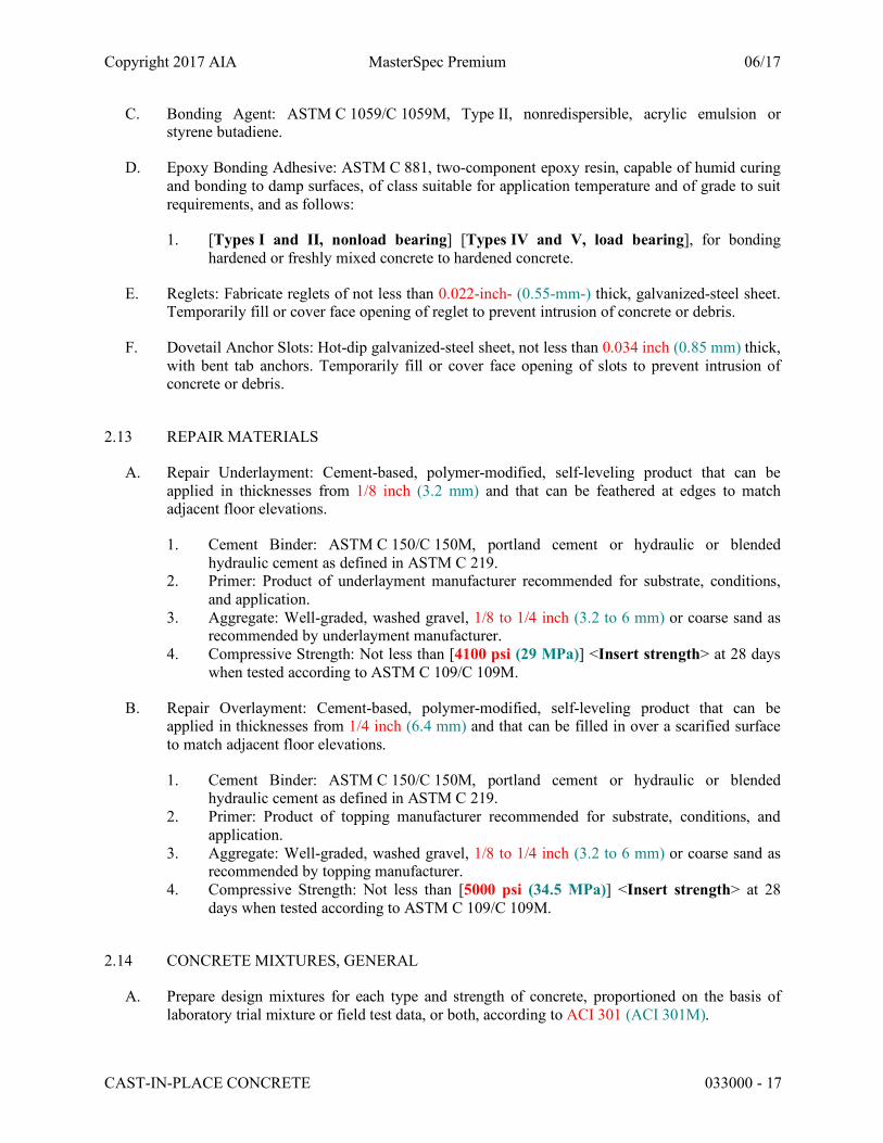
C. Bonding Agent: ASTM C 1059/C 1059M, Type II, nonredispersible, acrylic emulsion or styrene butadiene.
D. Epoxy Bonding Adhesive: ASTM C 881, two-component epoxy resin, capable of humid curing and bonding to damp surfaces, of class suitable for application temperature and of grade to suit requirements, and as follows:
1. [Types I and II, nonload bearing] [Types IV and V, load bearing], for bonding hardened or freshly mixed concrete to hardened concrete.
E. Reglets: Fabricate reglets of not less than 0.022-inch- (0.55-mm-) thick, galvanized-steel sheet. Temporarily fill or cover face opening of reglet to prevent intrusion of concrete or debris.
F. Dovetail Anchor Slots: Hot-dip galvanized-steel sheet, not less than 0.034 inch (0.85 mm) thick, with bent tab anchors. Temporarily fill or cover face opening of slots to prevent intrusion of concrete or debris.
2.13 REPAIR MATERIALS
A. Repair Underlayment: Cement-based, polymer-modified, self-leveling product that can be applied in thicknesses from 1/8 inch (3.2 mm) and that can be feathered at edges to match adjacent floor elevations.
1. Cement Binder: ASTM C 150/C 150M, portland cement or hydraulic or blended hydraulic cement as defined in ASTM C 219.
2. Primer: Product of underlayment manufacturer recommended for substrate, conditions, and application.
3. Aggregate: Well-graded, washed gravel, 1/8 to 1/4 inch (3.2 to 6 mm) or coarse sand as recommended by underlayment manufacturer.
4. Compressive Strength: Not less than [4100 psi (29 MPa)] <Insert strength> at 28 days when tested according to ASTM C 109/C 109M.
B. Repair Overlayment: Cement-based, polymer-modified, self-leveling product that can be applied in thicknesses from 1/4 inch (6.4 mm) and that can be filled in over a scarified surface to match adjacent floor elevations.
1. Cement Binder: ASTM C 150/C 150M, portland cement or hydraulic or blended hydraulic cement as defined in ASTM C 219.
2. Primer: Product of topping manufacturer recommended for substrate, conditions, and application.
3. Aggregate: Well-graded, washed gravel, 1/8 to 1/4 inch (3.2 to 6 mm) or coarse sand as recommended by topping manufacturer.
4. Compressive Strength: Not less than [5000 psi (34.5 MPa)] <Insert strength> at 28 days when tested according to ASTM C 109/C 109M.
2.14 CONCRETE MIXTURES, GENERAL
A. Prepare design mixtures for each type and strength of concrete, proportioned on the basis of laboratory trial mixture or field test data, or both, according to ACI 301 (ACI 301M).

Copyright 2017 AIA MasterSpec Premium 06/17
CAST-IN-PLACE CONCRETE 033000 - 18
1. Use a qualified independent testing agency for preparing and reporting proposed mixture designs based on laboratory trial mixtures.
B. Cementitious Materials:[ Use fly ash, pozzolan, slag cement, and silica fume as needed to reduce the total amount of portland cement, which would otherwise be used, by not less than 40 percent.] [ Limit percentage, by weight, of cementitious materials other than portland cement in concrete as follows:]
1. Fly Ash: 25 percent. 2. Combined Fly Ash and Pozzolan: 25 percent. 3. Slag Cement: 50 percent. 4. Combined Fly Ash or Pozzolan and Slag Cement: 50 percent portland cement minimum,
with fly ash or pozzolan not exceeding 25 percent. 5. Silica Fume: 10 percent. 6. Combined Fly Ash, Pozzolans, and Silica Fume: 35 percent with fly ash or pozzolans not
exceeding 25 percent and silica fume not exceeding 10 percent. 7. Combined Fly Ash or Pozzolans, Slag Cement, and Silica Fume: 50 percent with fly ash
or pozzolans not exceeding 25 percent and silica fume not exceeding 10 percent.
C. Limit water-soluble, chloride-ion content in hardened concrete to [0.06] [0.15] [0.30] [1.00] <Insert number> percent by weight of cement.
D. Admixtures: Use admixtures according to manufacturer's written instructions.
1. Use [water-reducing] [high-range water-reducing] [or] [plasticizing] admixture in concrete, as required, for placement and workability.
2. Use water-reducing and -retarding admixture when required by high temperatures, low humidity, or other adverse placement conditions.
3. Use water-reducing admixture in pumped concrete, concrete for heavy-use industrial slabs and parking structure slabs, concrete required to be watertight, and concrete with a w/c ratio below 0.50.
4. Use corrosion-inhibiting admixture in concrete mixtures where indicated. 5. Use of Porosity Inhibiting Admixture (PIA) where indicated.
E. Color Pigment: Add color pigment to concrete mixture according to manufacturer's written instructions and to result in hardened concrete color consistent with approved mockup.
2.15 CONCRETE MIXTURES FOR BUILDING ELEMENTS
A. Footings: Normal-weight concrete.
1. Minimum Compressive Strength: [5000 psi (34.5 MPa)] [4500 psi (31 MPa)] [4000 psi (27.6 MPa)] [3500 psi (24.1 MPa)] [3000 psi (20.7 MPa)] [As indicated] <Insert strength> at 28 days.
2. Maximum W/C Ratio: [0.50] [0.45] [0.40] <Insert number>. 3. Slump Limit: [4 inches (100 mm)] [5 inches (125 mm)] [8 inches (200 mm) for
concrete with verified slump of 2 to 4 inches (50 to 100 mm) before adding high-range water-reducing admixture or plasticizing admixture] <Insert limits>, plus or minus 1 inch (25 mm).

Copyright 2017 AIA MasterSpec Premium 06/17
CAST-IN-PLACE CONCRETE 033000 - 19
4. Air Content: [5.5] <Insert number> percent, plus or minus 1.5 percent at point of delivery for 1-1/2-inch (38-mm) nominal maximum aggregate size.
5. Air Content: [6] <Insert number> percent, plus or minus 1.5 percent at point of delivery for [1-inch (25-mm)] [3/4-inch (19-mm)] nominal maximum aggregate size.
B. Foundation Walls: Normal-weight concrete.
1. Minimum Compressive Strength: [5000 psi (34.5 MPa)] [4500 psi (31 MPa)] [4000 psi (27.6 MPa)] [3500 psi (24.1 MPa)] [3000 psi (20.7 MPa)] [As indicated] <Insert strength> at 28 days.
2. Maximum W/C Ratio: [0.50] [0.45] [0.40] <Insert number>. 3. Slump Limit: [4 inches (100 mm)] [5 inches (125 mm)] [8 inches (200 mm) for
concrete with verified slump of 2 to 4 inches (50 to 100 mm) before adding high-range water-reducing admixture or plasticizing admixture] <Insert limits>, plus or minus 1 inch (25 mm).
4. Air Content: [5.5] <Insert number> percent, plus or minus 1.5 percent at point of delivery for 1-1/2-inch (38-mm) nominal maximum aggregate size.
5. Air Content: [6] <Insert number> percent, plus or minus 1.5 percent at point of delivery for [1-inch (25-mm)] [3/4-inch (19-mm)] nominal maximum aggregate size.
C. Slabs-on-Grade: Normal-weight concrete.
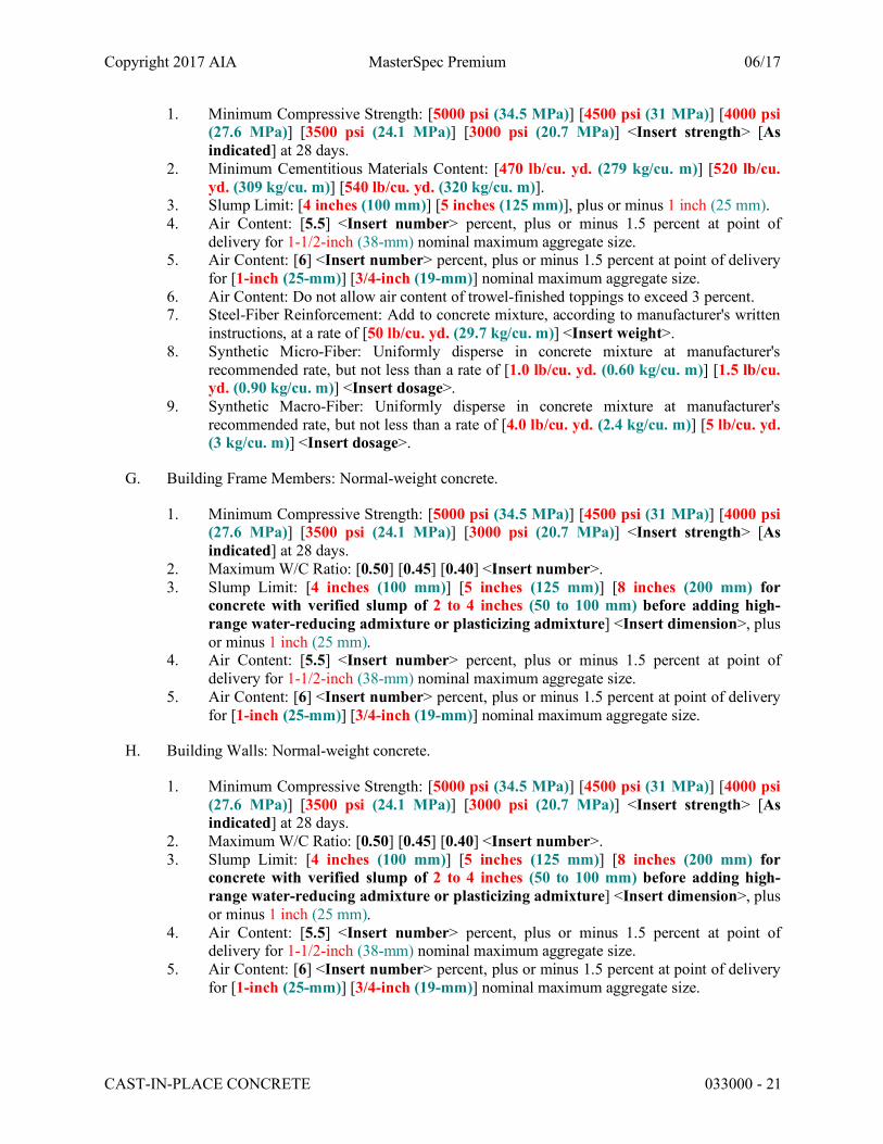
1. Minimum Compressive Strength: [5000 psi (34.5 MPa)] [4500 psi (31 MPa)] [4000 psi (27.6 MPa)] [3500 psi (24.1 MPa)] [3000 psi (20.7 MPa)] [As indicated] <Insert strength> at 28 days.
2. Maximum W/C Ratio: [0.50] [0.45] [0.40] <Insert number>. 3. Minimum Cementitious Materials Content: [470 lb/cu. yd. (279 kg/cu. m)] [520 lb/cu.
yd. (309 kg/cu. m)] [540 lb/cu. yd. (320 kg/cu. m)]. 4. Slump Limit: [4 inches (100 mm)] [5 inches (125 mm)] [8 inches (200 mm) for
concrete with verified slump of 2 to 4 inches (50 to 100 mm) before adding high-range water-reducing admixture or plasticizing admixture] <Insert limits>, plus or minus 1 inch (25 mm).
5. Air Content: [5.5] <Insert number> percent, plus or minus 1.5 percent at point of delivery for 1-1/2-inch (38-mm) nominal maximum aggregate size.
6. Air Content: [6] <Insert number> percent, plus or minus 1.5 percent at point of delivery for [1-inch (25-mm)] [3/4-inch (19-mm)] nominal maximum aggregate size.
7. Air Content: Do not allow air content of trowel-finished floors to exceed 3 percent. 8. Steel-Fiber Reinforcement: Add to concrete mixture, according to manufacturer's written
instructions, at a rate of [50 lb/cu. yd. (29.7 kg/cu. m)] <Insert weight>. 9. Synthetic Micro-Fiber: Uniformly disperse in concrete mixture at manufacturer's
recommended rate, but not less than a rate of [1.0 lb/cu. yd. (0.60 kg/cu. m)] [1.5 lb/cu. yd. (0.90 kg/cu. m)] <Insert dosage>.
10. Synthetic Macro-Fiber: Uniformly disperse in concrete mixture at manufacturer's recommended rate, but not less than a rate of [4.0 lb/cu. yd. (2.4 kg/cu. m)] [5 lb/cu. yd. (3 kg/cu. m)] <Insert dosage>.
D. Suspended Slabs: Normal-weight concrete.
1. Minimum Compressive Strength: [5000 psi (34.5 MPa)] [4500 psi (31 MPa)] [4000 psi (27.6 MPa)] [3500 psi (24.1 MPa)] [3000 psi (20.7 MPa)] <Insert strength> [As indicated] at 28 days.

Copyright 2017 AIA MasterSpec Premium 06/17
CAST-IN-PLACE CONCRETE 033000 - 20
2. Maximum W/C Ratio: [0.50] [0.45] [0.40] <Insert number>. 3. Minimum Cementitious Materials Content: [470 lb/cu. yd. (279 kg/cu. m)] [520 lb/cu.
yd. (309 kg/cu. m)] [540 lb/cu. yd. (320 kg/cu. m)]. 4. Slump Limit: [4 inches (100 mm)] [5 inches (125 mm)] [8 inches (200 mm) for
concrete with verified slump of 2 to 4 inches (50 to 100 mm) before adding high-range water-reducing admixture or plasticizing admixture] <Insert limits>, plus or minus 1 inch (25 mm).
5. Air Content: [5.5] <Insert number> percent, plus or minus 1.5 percent at point of delivery for 1-1/2-inch (38-mm) nominal maximum aggregate size.
6. Air Content: [6] <Insert number> percent, plus or minus 1.5 percent at point of delivery for [1-inch (25-mm)] [3/4-inch (19-mm)] nominal maximum aggregate size.
7. Air Content: Do not allow air content of trowel-finished floors to exceed 3 percent. 8. Steel-Fiber Reinforcement: Add to concrete mixture, according to manufacturer's written
instructions, at a rate of [50 lb/cu. yd. (29.7 kg/cu. m)] <Insert weight>. 9. Synthetic Micro-Fiber: Uniformly disperse in concrete mixture at manufacturer's
recommended rate, but not less than a rate of [1.0 lb/cu. yd. (0.60 kg/cu. m)] [1.5 lb/cu. yd. (0.90 kg/cu. m)] <Insert dosage>.
10. Synthetic Macro-Fiber: Uniformly disperse in concrete mixture at manufacturer's recommended rate, but not less than a rate of [4.0 lb/cu. yd. (2.4 kg/cu. m)] [5 lb/cu. yd. (3 kg/cu. m)] <Insert dosage>.
E. Suspended Slabs: Lightweight concrete.
1. Minimum Compressive Strength: [5000 psi (34.5 MPa)] [4500 psi (31 MPa)] [4000 psi (27.6 MPa)] [3500 psi (24.1 MPa)] [3000 psi (20.7 MPa)] <Insert strength> [As indicated] at 28 days.
2. Calculated Equilibrium Unit Weight: [115 lb/cu. ft. (1842 kg/cu. m)] [110 lb/cu. ft. (1762 kg/cu. m)] [105 lb/cu. ft. (1682 kg/cu. m)], plus or minus 3 lb/cu. ft. (48.1 kg/cu. m) as determined by ASTM C 567/C 567M.
3. Slump Limit: [4 inches (100 mm)] [5 inches (125 mm)] [8 inches (200 mm) for concrete with verified slump of 2 to 4 inches (50 to 100 mm) before adding high-range water-reducing admixture or plasticizing admixture] <Insert limits>, plus or minus 1 inch (25 mm).
4. Air Content: 6 percent, plus or minus 2 percent at point of delivery for nominal maximum aggregate size greater than 3/8 inch (10 mm).
5. Air Content: 7 percent, plus or minus 2 percent at point of delivery for nominal maximum aggregate size 3/8 inch (10 mm) or less.
6. Air Content: Do not allow air content of trowel-finished floors to exceed 3 percent. 7. Steel-Fiber Reinforcement: Add to concrete mixture, according to manufacturer's written
instructions, at a rate of [50 lb/cu. yd. (29.7 kg/cu. m)] <Insert weight>. 8. Synthetic Micro-Fiber: Uniformly disperse in concrete mixture at manufacturer's
recommended rate, but not less than a rate of [1.0 lb/cu. yd. (0.60 kg/cu. m)] [1.5 lb/cu. yd. (0.90 kg/cu. m)] <Insert dosage>.
9. Synthetic Macro-Fiber: Uniformly disperse in concrete mixture at manufacturer's recommended rate, but not less than a rate of [4.0 lb/cu. yd. (2.4 kg/cu. m)] [5 lb/cu. yd. (3 kg/cu. m)] <Insert dosage>.
F. Concrete Toppings: Normal-weight concrete.
Copyright 2017 AIA MasterSpec Premium 06/17
CAST-IN-PLACE CONCRETE 033000 - 21
1. Minimum Compressive Strength: [5000 psi (34.5 MPa)] [4500 psi (31 MPa)] [4000 psi (27.6 MPa)] [3500 psi (24.1 MPa)] [3000 psi (20.7 MPa)] <Insert strength> [As indicated] at 28 days.
2. Minimum Cementitious Materials Content: [470 lb/cu. yd. (279 kg/cu. m)] [520 lb/cu. yd. (309 kg/cu. m)] [540 lb/cu. yd. (320 kg/cu. m)].
3. Slump Limit: [4 inches (100 mm)] [5 inches (125 mm)], plus or minus 1 inch (25 mm). 4. Air Content: [5.5] <Insert number> percent, plus or minus 1.5 percent at point of
delivery for 1-1/2-inch (38-mm) nominal maximum aggregate size. 5. Air Content: [6] <Insert number> percent, plus or minus 1.5 percent at point of delivery
for [1-inch (25-mm)] [3/4-inch (19-mm)] nominal maximum aggregate size. 6. Air Content: Do not allow air content of trowel-finished toppings to exceed 3 percent. 7. Steel-Fiber Reinforcement: Add to concrete mixture, according to manufacturer's written
instructions, at a rate of [50 lb/cu. yd. (29.7 kg/cu. m)] <Insert weight>. 8. Synthetic Micro-Fiber: Uniformly disperse in concrete mixture at manufacturer's
recommended rate, but not less than a rate of [1.0 lb/cu. yd. (0.60 kg/cu. m)] [1.5 lb/cu. yd. (0.90 kg/cu. m)] <Insert dosage>.
9. Synthetic Macro-Fiber: Uniformly disperse in concrete mixture at manufacturer's recommended rate, but not less than a rate of [4.0 lb/cu. yd. (2.4 kg/cu. m)] [5 lb/cu. yd. (3 kg/cu. m)] <Insert dosage>.
G. Building Frame Members: Normal-weight concrete.
1. Minimum Compressive Strength: [5000 psi (34.5 MPa)] [4500 psi (31 MPa)] [4000 psi (27.6 MPa)] [3500 psi (24.1 MPa)] [3000 psi (20.7 MPa)] <Insert strength> [As indicated] at 28 days.
2. Maximum W/C Ratio: [0.50] [0.45] [0.40] <Insert number>. 3. Slump Limit: [4 inches (100 mm)] [5 inches (125 mm)] [8 inches (200 mm) for
concrete with verified slump of 2 to 4 inches (50 to 100 mm) before adding high-range water-reducing admixture or plasticizing admixture] <Insert dimension>, plus or minus 1 inch (25 mm).
4. Air Content: [5.5] <Insert number> percent, plus or minus 1.5 percent at point of delivery for 1-1/2-inch (38-mm) nominal maximum aggregate size.
5. Air Content: [6] <Insert number> percent, plus or minus 1.5 percent at point of delivery for [1-inch (25-mm)] [3/4-inch (19-mm)] nominal maximum aggregate size.
H. Building Walls: Normal-weight concrete.
1. Minimum Compressive Strength: [5000 psi (34.5 MPa)] [4500 psi (31 MPa)] [4000 psi (27.6 MPa)] [3500 psi (24.1 MPa)] [3000 psi (20.7 MPa)] <Insert strength> [As indicated] at 28 days.
2. Maximum W/C Ratio: [0.50] [0.45] [0.40] <Insert number>. 3. Slump Limit: [4 inches (100 mm)] [5 inches (125 mm)] [8 inches (200 mm) for
concrete with verified slump of 2 to 4 inches (50 to 100 mm) before adding high-range water-reducing admixture or plasticizing admixture] <Insert dimension>, plus or minus 1 inch (25 mm).
4. Air Content: [5.5] <Insert number> percent, plus or minus 1.5 percent at point of delivery for 1-1/2-inch (38-mm) nominal maximum aggregate size.
5. Air Content: [6] <Insert number> percent, plus or minus 1.5 percent at point of delivery for [1-inch (25-mm)] [3/4-inch (19-mm)] nominal maximum aggregate size.
Copyright 2017 AIA MasterSpec Premium 06/17
CAST-IN-PLACE CONCRETE 033000 - 22
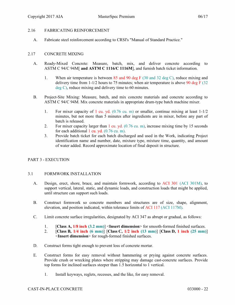
2.16 FABRICATING REINFORCEMENT
A. Fabricate steel reinforcement according to CRSI's "Manual of Standard Practice."
2.17 CONCRETE MIXING
A. Ready-Mixed Concrete: Measure, batch, mix, and deliver concrete according to ASTM C 94/C 94M[ and ASTM C 1116/C 1116M], and furnish batch ticket information.
1. When air temperature is between 85 and 90 deg F (30 and 32 deg C), reduce mixing and delivery time from 1-1/2 hours to 75 minutes; when air temperature is above 90 deg F (32 deg C), reduce mixing and delivery time to 60 minutes.
B. Project-Site Mixing: Measure, batch, and mix concrete materials and concrete according to ASTM C 94/C 94M. Mix concrete materials in appropriate drum-type batch machine mixer.
1. For mixer capacity of 1 cu. yd. (0.76 cu. m) or smaller, continue mixing at least 1-1/2 minutes, but not more than 5 minutes after ingredients are in mixer, before any part of batch is released.
2. For mixer capacity larger than 1 cu. yd. (0.76 cu. m), increase mixing time by 15 seconds for each additional 1 cu. yd. (0.76 cu. m).
3. Provide batch ticket for each batch discharged and used in the Work, indicating Project identification name and number, date, mixture type, mixture time, quantity, and amount of water added. Record approximate location of final deposit in structure.
PART 3 - EXECUTION
3.1 FORMWORK INSTALLATION
A. Design, erect, shore, brace, and maintain formwork, according to ACI 301 (ACI 301M), to support vertical, lateral, static, and dynamic loads, and construction loads that might be applied, until structure can support such loads.
B. Construct formwork so concrete members and structures are of size, shape, alignment, elevation, and position indicated, within tolerance limits of ACI 117 (ACI 117M).
C. Limit concrete surface irregularities, designated by ACI 347 as abrupt or gradual, as follows:
1. [Class A, 1/8 inch (3.2 mm)] <Insert dimension> for smooth-formed finished surfaces. 2. [Class B, 1/4 inch (6 mm)] [Class C, 1/2 inch (13 mm)] [Class D, 1 inch (25 mm)]
<Insert dimension> for rough-formed finished surfaces.
D. Construct forms tight enough to prevent loss of concrete mortar.
E. Construct forms for easy removal without hammering or prying against concrete surfaces. Provide crush or wrecking plates where stripping may damage cast-concrete surfaces. Provide top forms for inclined surfaces steeper than 1.5 horizontal to 1 vertical.
1. Install keyways, reglets, recesses, and the like, for easy removal.

Copyright 2017 AIA MasterSpec Premium 06/17
CAST-IN-PLACE CONCRETE 033000 - 23
2. Do not use rust-stained steel form-facing material.
F. Set edge forms, bulkheads, and intermediate screed strips for slabs to achieve required elevations and slopes in finished concrete surfaces. Provide and secure units to support screed strips; use strike-off templates or compacting-type screeds.
G. Provide temporary openings for cleanouts and inspection ports where interior area of formwork is inaccessible. Close openings with panels tightly fitted to forms and securely braced to prevent loss of concrete mortar. Locate temporary openings in forms at inconspicuous locations.
H. [Chamfer] [Do not chamfer] exterior corners and edges of permanently exposed concrete.
I. Form openings, chases, offsets, sinkages, keyways, reglets, blocking, screeds, and bulkheads required in the Work. Determine sizes and locations from trades providing such items.
J. Clean forms and adjacent surfaces to receive concrete. Remove chips, wood, sawdust, dirt, and other debris just before placing concrete.
K. Retighten forms and bracing before placing concrete, as required, to prevent mortar leaks and maintain proper alignment.
L. Coat contact surfaces of forms with form-release agent, according to manufacturer's written instructions, before placing reinforcement.
3.2 EMBEDDED ITEM INSTALLATION
A. Place and secure anchorage devices and other embedded items required for adjoining work that is attached to or supported by cast-in-place concrete. Use setting drawings, templates, diagrams, instructions, and directions furnished with items to be embedded.
1. Install anchor rods, accurately located, to elevations required and complying with tolerances in Section 7.5 of AISC 303.
2. Install reglets to receive waterproofing and to receive through-wall flashings in outer face of concrete frame at exterior walls, where flashing is shown at lintels, shelf angles, and other conditions.
3. Install dovetail anchor slots in concrete structures as indicated.
3.3 REMOVING AND REUSING FORMS
A. General: Formwork for sides of beams, walls, columns, and similar parts of the Work that does not support weight of concrete may be removed after cumulatively curing at not less than 50 deg F (10 deg C) for [24] <Insert number> hours after placing concrete. Concrete has to be hard enough to not be damaged by form-removal operations, and curing and protection operations need to be maintained.
1. Leave formwork for beam soffits, joists, slabs, and other structural elements that support weight of concrete in place until concrete has achieved[ at least 70 percent of] its 28-day design compressive strength.

Copyright 2017 AIA MasterSpec Premium 06/17
CAST-IN-PLACE CONCRETE 033000 - 24
2. Remove forms only if shores have been arranged to permit removal of forms without loosening or disturbing shores.
B. Clean and repair surfaces of forms to be reused in the Work. Split, frayed, delaminated, or otherwise damaged form-facing material are not acceptable for exposed surfaces. Apply new form-release agent.
C. When forms are reused, clean surfaces, remove fins and laitance, and tighten to close joints. Align and secure joints to avoid offsets. Do not use patched forms for exposed concrete surfaces unless approved by Architect.
3.4 SHORING AND RESHORING INSTALLATION
A. Comply with ACI 318 (ACI 318M) and ACI 301 (ACI 301M) for design, installation, and removal of shoring and reshoring.
1. Do not remove shoring or reshoring until measurement of slab tolerances is complete.
B. In multistory construction, extend shoring or reshoring over a sufficient number of stories to distribute loads in such a manner that no floor or member will be excessively loaded or will induce tensile stress in concrete members without sufficient steel reinforcement.
C. Plan sequence of removal of shores and reshore to avoid damage to concrete. Locate and provide adequate reshoring to support construction without excessive stress or deflection.
3.5 VAPOR-RETARDER INSTALLATION
A. Sheet Vapor Retarders: Place, protect, and repair sheet vapor retarder according to ASTM E 1643 and manufacturer's written instructions.
1. Lap joints 6 inches (150 mm) and seal with manufacturer's recommended tape.
B. Bituminous Vapor Retarders: Place, protect, and repair bituminous vapor retarder according to manufacturer's written instructions.
3.6 STEEL REINFORCEMENT INSTALLATION
A. General: Comply with CRSI's "Manual of Standard Practice" for fabricating, placing, and supporting reinforcement.
1. Do not cut or puncture vapor retarder. Repair damage and reseal vapor retarder before placing concrete.
B. Clean reinforcement of loose rust and mill scale, earth, ice, and other foreign materials that reduce bond to concrete.
C. Accurately position, support, and secure reinforcement against displacement. Locate and support reinforcement with bar supports to maintain minimum concrete cover. Do not tack weld crossing reinforcing bars.

Copyright 2017 AIA MasterSpec Premium 06/17
CAST-IN-PLACE CONCRETE 033000 - 25
1. Weld reinforcing bars according to AWS D1.4/D 1.4M, where indicated.
D. Set wire ties with ends directed into concrete, not toward exposed concrete surfaces.
E. Install welded-wire reinforcement in longest practicable lengths on bar supports spaced to minimize sagging. Lap edges and ends of adjoining sheets at least one mesh spacing. Offset laps of adjoining sheet widths to prevent continuous laps in either direction. Lace overlaps with wire.
F. Epoxy-Coated Reinforcement: Repair cut and damaged epoxy coatings with epoxy repair coating according to ASTM D 3963/D 3963M. Use epoxy-coated steel wire ties to fasten epoxy-coated steel reinforcement.
G. Zinc-Coated Reinforcement: Repair cut and damaged zinc coatings with zinc repair material according to ASTM A 780/A 780M. Use galvanized-steel wire ties to fasten zinc-coated steel reinforcement.
3.7 JOINTS
A. General: Construct joints true to line with faces perpendicular to surface plane of concrete.
B. Construction Joints: Install so strength and appearance of concrete are not impaired, at locations indicated or as approved by Architect.
1. Place joints perpendicular to main reinforcement. Continue reinforcement across construction joints unless otherwise indicated. Do not continue reinforcement through sides of strip placements of floors and slabs.
2. Form keyed joints as indicated. Embed keys at least 1-1/2 inches (38 mm) into concrete. 3. Locate joints for beams, slabs, joists, and girders in the middle third of spans. Offset
joints in girders a minimum distance of twice the beam width from a beam-girder intersection.
4. Locate horizontal joints in walls and columns at underside of floors, slabs, beams, and girders and at the top of footings or floor slabs.
5. Space vertical joints in walls [as indicated] <Insert spacing>. Locate joints beside piers integral with walls, near corners, and in concealed locations where possible.
6. Use a bonding agent at locations where fresh concrete is placed against hardened or partially hardened concrete surfaces.
7. Use epoxy-bonding adhesive at locations where fresh concrete is placed against hardened or partially hardened concrete surfaces.
C. Contraction Joints in Slabs-on-Grade: Form weakened-plane contraction joints, sectioning concrete into areas as indicated. Construct contraction joints for a depth equal to at least [one-fourth] <Insert depth> of concrete thickness as follows:
1. Grooved Joints: Form contraction joints after initial floating by grooving and finishing each edge of joint to a radius of 1/8 inch (3.2 mm). Repeat grooving of contraction joints after applying surface finishes. Eliminate groover tool marks on concrete surfaces.
2. Sawed Joints: Form contraction joints with power saws equipped with shatterproof abrasive or diamond-rimmed blades. Cut 1/8-inch- (3.2-mm-) wide joints into concrete when cutting action does not tear, abrade, or otherwise damage surface and before concrete develops random contraction cracks.

Copyright 2017 AIA MasterSpec Premium 06/17
CAST-IN-PLACE CONCRETE 033000 - 26
D. Isolation Joints in Slabs-on-Grade: After removing formwork, install joint-filler strips at slab junctions with vertical surfaces, such as column pedestals, foundation walls, grade beams, and other locations, as indicated.
1. Extend joint-filler strips full width and depth of joint, terminating flush with finished concrete surface unless otherwise indicated.
2. Terminate full-width joint-filler strips not less than 1/2 inch (13 mm) or more than 1 inch (25 mm) below finished concrete surface where joint sealants, specified in Section 079200 "Joint Sealants," are indicated.
3. Install joint-filler strips in lengths as long as practicable. Where more than one length is required, lace or clip sections together.
E. Doweled Joints: Install dowel bars and support assemblies at joints where indicated. Lubricate or asphalt coat one-half of dowel length to prevent concrete bonding to one side of joint.
3.8 WATERSTOP INSTALLATION
A. Flexible Waterstops: Install in construction joints and at other joints indicated to form a continuous diaphragm. Install in longest lengths practicable. Support and protect exposed waterstops during progress of the Work. Field fabricate joints in waterstops according to manufacturer's written instructions.
B. Self-Expanding Strip Waterstops: Install in construction joints and at other locations indicated, according to manufacturer's written instructions, adhesive bonding, mechanically fastening, and firmly pressing into place. Install in longest lengths practicable.
3.9 CONCRETE PLACEMENT
A. Before placing concrete, verify that installation of formwork, reinforcement, and embedded items is complete and that required inspections are completed.
B. Do not add water to concrete during delivery, at Project site, or during placement unless approved by Architect.
C. Before test sampling and placing concrete, water may be added at Project site, subject to limitations of ACI 301 (ACI 301M).
1. Do not add water to concrete after adding high-range water-reducing admixtures to mixture.
D. Deposit concrete continuously in one layer or in horizontal layers of such thickness that no new concrete is placed on concrete that has hardened enough to cause seams or planes of weakness. If a section cannot be placed continuously, provide construction joints as indicated. Deposit concrete to avoid segregation.
1. Deposit concrete in horizontal layers of depth not to exceed formwork design pressures and in a manner to avoid inclined construction joints.
2. Consolidate placed concrete with mechanical vibrating equipment according to ACI 301 (ACI 301M).
Copyright 2017 AIA MasterSpec Premium 06/17
CAST-IN-PLACE CONCRETE 033000 - 27
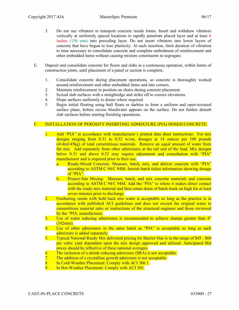
3. Do not use vibrators to transport concrete inside forms. Insert and withdraw vibrators vertically at uniformly spaced locations to rapidly penetrate placed layer and at least 6 inches (150 mm) into preceding layer. Do not insert vibrators into lower layers of concrete that have begun to lose plasticity. At each insertion, limit duration of vibration to time necessary to consolidate concrete and complete embedment of reinforcement and other embedded items without causing mixture constituents to segregate.
E. Deposit and consolidate concrete for floors and slabs in a continuous operation, within limits of construction joints, until placement of a panel or section is complete.
1. Consolidate concrete during placement operations, so concrete is thoroughly worked around reinforcement and other embedded items and into corners.
2. Maintain reinforcement in position on chairs during concrete placement. 3. Screed slab surfaces with a straightedge and strike off to correct elevations. 4. Slope surfaces uniformly to drains where required. 5. Begin initial floating using bull floats or darbies to form a uniform and open-textured
surface plane, before excess bleedwater appears on the surface. Do not further disturb slab surfaces before starting finishing operations.
F. INSTALLATION OF PEROSITY INHIBITING ADMIXTURE (PIA) DOSED CONCRETE:
1. Add “PIA” in accordance with manufacturer’s printed data sheet instructions: For mix designs ranging from 0.31 to 0.52 w/cm, dosages at 14 ounces per 100 pounds (414ml/45kg) of total cementitious materials. Remove an equal amount of water from the mix. Add separately from other admixtures at the tail end of the load. Mix designs below 0.31 and above 0.52 may require adjustment and consultation with “PIA” manufacturer and is required prior to their use. a. Ready-Mixed Concrete: Measure, batch, mix, and deliver concrete with “PIA”
according to ASTM C 94/C 94M; furnish batch ticket information showing dosage of “PIA”.
b. Project-Site Mixing: Measure, batch, and mix concrete materials and concrete according to ASTM C 94/C 94M. Add the “PIA” to where it makes direct contact with the ready-mix material and then rotate drum of batch truck on high for at least seven minutes prior to discharge.
2. Freshening onsite with held back mix water is acceptable so long as the practice is in accordance with published ACI guidelines and does not exceed the original water to cementitious material ratio or instructions of the structural engineer and those reviewed by the “PIA: manufacturer.
3. Use of water reducing admixtures is recommended to achieve slumps greater than 4” (102mm).
4. Use of other admixtures in the same batch as “PIA” is acceptable so long as each admixture is added separately.
5. Typical National Ready Mix delivered pricing for Barrier One is in the range of $45 - $60 per cubic yard dependent upon the mix design approved and utilized. Anticipated Bid prices should be reflective of these national averages.
6. The inclusion of a shrink reducing admixture (SRA) is not acceptable. 7. The addition of a crystalline growth admixture is not acceptable. 8. In Cold-Weather Placement: Comply with ACI 306.1. 9. In Hot-Weather Placement: Comply with ACI 305.
Copyright 2017 AIA MasterSpec Premium 06/17
CAST-IN-PLACE CONCRETE 033000 - 28
3.10 FINISHING FORMED SURFACES
A. Rough-Formed Finish: As-cast concrete texture imparted by form-facing material with tie holes and defects repaired and patched. Remove fins and other projections that exceed specified limits on formed-surface irregularities.
1. Apply to concrete surfaces [not exposed to public view] <Insert locations>.
B. Smooth-Formed Finish: As-cast concrete texture imparted by form-facing material, arranged in an orderly and symmetrical manner with a minimum of seams. Repair and patch tie holes and defects. Remove fins and other projections that exceed specified limits on formed-surface irregularities.
1. Apply to concrete surfaces [exposed to public view,] [to receive a rubbed finish,] [or to be covered with a coating or covering material applied directly to concrete] <Insert locations>.
C. Rubbed Finish: Apply the following to smooth-formed-finished as-cast concrete where indicated:
1. Smooth-Rubbed Finish: Not later than one day after form removal, moisten concrete surfaces and rub with carborundum brick or another abrasive until producing a uniform color and texture. Do not apply cement grout other than that created by the rubbing process.
2. Grout-Cleaned Finish: Wet concrete surfaces and apply grout of a consistency of thick paint to coat surfaces and fill small holes. Mix 1 part portland cement to 1-1/2 parts fine sand with a 1:1 mixture of bonding admixture and water. Add white portland cement in amounts determined by trial patches, so color of dry grout matches adjacent surfaces. Scrub grout into voids and remove excess grout. When grout whitens, rub surface with clean burlap and keep surface damp by fog spray for at least 36 hours.
3. Cork-Floated Finish: Wet concrete surfaces and apply a stiff grout. Mix 1 part portland cement and 1 part fine sand with a 1:1 mixture of bonding agent and water. Add white portland cement in amounts determined by trial patches, so color of dry grout matches adjacent surfaces. Compress grout into voids by grinding surface. In a swirling motion, finish surface with a cork float.
D. Related Unformed Surfaces: At tops of walls, horizontal offsets, and similar unformed surfaces adjacent to formed surfaces, strike off smooth and finish with a texture matching adjacent formed surfaces. Continue final surface treatment of formed surfaces uniformly across adjacent unformed surfaces unless otherwise indicated.
3.11 FINISHING FLOORS AND SLABS
A. General: Comply with ACI 302.1R recommendations for screeding, restraightening, and finishing operations for concrete surfaces. Do not wet concrete surfaces.
B. Scratch Finish: While still plastic, texture concrete surface that has been screeded and bull-floated or darbied. Use stiff brushes, brooms, or rakes to produce a profile amplitude of 1/4 inch (6 mm) in one direction.
Copyright 2017 AIA MasterSpec Premium 06/17
CAST-IN-PLACE CONCRETE 033000 - 29
1. Apply scratch finish to surfaces [indicated] [and] [to receive concrete floor toppings] [to receive mortar setting beds for bonded cementitious floor finishes] <Insert locations>.
C. Float Finish: Consolidate surface with power-driven floats or by hand floating if area is small or inaccessible to power-driven floats. Restraighten, cut down high spots, and fill low spots. Repeat float passes and restraightening until surface is left with a uniform, smooth, granular texture.
1. Apply float finish to surfaces [indicated] [to receive trowel finish] [and] [to be covered with fluid-applied or sheet waterproofing, built-up or membrane roofing, or sand-bed terrazzo] <Insert locations>.
D. Trowel Finish: After applying float finish, apply first troweling and consolidate concrete by hand or power-driven trowel. Continue troweling passes and restraighten until surface is free of trowel marks and uniform in texture and appearance. Grind smooth any surface defects that would telegraph through applied coatings or floor coverings.
1. Apply a trowel finish to surfaces [indicated] [exposed to view] [or] [to be covered with resilient flooring, carpet, ceramic or quarry tile set over a cleavage membrane, paint, or another thin-film-finish coating system] <Insert locations>.
2. Finish surfaces to the following tolerances, according to ASTM E 1155 (ASTM E 1155M), for a randomly trafficked floor surface:
a. Specified overall values of flatness, F(F) 25; and of levelness, F(L) 20; with minimum local values of flatness, F(F) 17; and of levelness, F(L) 15.
b. Specified overall values of flatness, F(F) 35; and of levelness, F(L) 25; with minimum local values of flatness, F(F) 24; and of levelness, F(L) 17; for slabs-on-grade.
c. Specified overall values of flatness, F(F) 30; and of levelness, F(L) 20; with minimum local values of flatness, F(F) 24; and of levelness, F(L) 15; for suspended slabs.
d. Specified overall values of flatness, F(F) 45; and of levelness, F(L) 35; with minimum local values of flatness, F(F) 30; and of levelness, F(L) 24.
3. Finish and measure surface, so gap at any point between concrete surface and an unleveled, freestanding, 10-ft.- (3.05-m-) long straightedge resting on two high spots and placed anywhere on the surface does not exceed [1/4 inch (6 mm)] [3/16 inch (4.8 mm)] [1/8 inch (3.2 mm)].
E. Trowel and Fine-Broom Finish: Apply a first trowel finish to surfaces [indicated] [where ceramic or quarry tile is to be installed by either thickset or thinset method]. While concrete is still plastic, slightly scarify surface with a fine broom.
1. Comply with flatness and levelness tolerances for trowel-finished floor surfaces.
F. Broom Finish: Apply a broom finish to exterior concrete platforms, steps, ramps, and elsewhere as indicated.
Copyright 2017 AIA MasterSpec Premium 06/17
CAST-IN-PLACE CONCRETE 033000 - 30
1. Immediately after float finishing, slightly roughen trafficked surface by brooming with fiber-bristle broom perpendicular to main traffic route. Coordinate required final finish with Architect before application.
G. Slip-Resistive Finish: Before final floating, apply slip-resistive [aggregate] [aluminum granule] finish where indicated and to concrete stair treads, platforms, and ramps. Apply according to manufacturer's written instructions and as follows:
1. Uniformly spread [25 lb/100 sq. ft. (12 kg/10 sq. m)] <Insert rate> of dampened slip-resistive [aggregate] [aluminum granules] over surface in one or two applications. Tamp aggregate flush with surface, but do not force below surface.
2. After broadcasting and tamping, apply float finish. 3. After curing, lightly work surface with a steel wire brush or an abrasive stone and water
to expose slip-resistive [aggregate] [aluminum granules].
H. Dry-Shake Floor Hardener Finish: After initial floating, apply dry-shake floor hardener to surfaces according to manufacturer's written instructions and as follows:
1. Uniformly apply dry-shake floor hardener at a rate of [100 lb/100 sq. ft. (49 kg/10 sq. m)] <Insert rate> unless greater amount is recommended by manufacturer.
2. Uniformly distribute approximately two-thirds of dry-shake floor hardener over surface by hand or with mechanical spreader, and embed by power floating. Follow power floating with a second dry-shake floor hardener application, uniformly distributing remainder of material, and embed by power floating.
3. After final floating, apply a trowel finish. Cure concrete with curing compound recommended by dry-shake floor hardener manufacturer and apply immediately after final finishing.
3.12 MISCELLANEOUS CONCRETE ITEM INSTALLATION
A. Filling In: Fill in holes and openings left in concrete structures after work of other trades is in place unless otherwise indicated. Mix, place, and cure concrete, as specified, to blend with in-place construction. Provide other miscellaneous concrete filling indicated or required to complete the Work.
B. Curbs: Provide monolithic finish to interior curbs by stripping forms while concrete is still green and by steel-troweling surfaces to a hard, dense finish with corners, intersections, and terminations slightly rounded.
C. Equipment Bases and Foundations:
1. Coordinate sizes and locations of concrete bases with actual equipment provided. 2. Construct concrete bases [4 inches (100 mm)] [6 inches (150 mm)] [8 inches (200 mm)]
<Insert dimension> high unless otherwise indicated, and extend base not less than 6 inches (150 mm) in each direction beyond the maximum dimensions of supported equipment unless otherwise indicated or unless required for seismic anchor support.
3. Minimum Compressive Strength: [5000 psi (34.5 MPa)] [4500 psi (31 MPa)] [4000 psi (27.6 MPa)] [3500 psi (24.1 MPa)] [3000 psi (20.7 MPa)] <Insert value> at 28 days.

Copyright 2017 AIA MasterSpec Premium 06/17
CAST-IN-PLACE CONCRETE 033000 - 31
4. Install dowel rods to connect concrete base to concrete floor. Unless otherwise indicated, install dowel rods on 18-inch (450-mm) centers around the full perimeter of concrete base.
5. For supported equipment, install epoxy-coated anchor bolts that extend through concrete base and anchor into structural concrete substrate.
6. Prior to pouring concrete, place and secure anchorage devices. Use setting drawings, templates, diagrams, instructions, and directions furnished with items to be embedded.
7. Cast anchor-bolt insert into bases. Install anchor bolts to elevations required for proper attachment to supported equipment.
D. Steel Pan Stairs: Provide concrete fill for steel pan stair treads, landings, and associated items. Cast-in inserts and accessories as shown on Drawings. Screed, tamp, and trowel finish concrete surfaces.
3.13 CONCRETE PROTECTING AND CURING
A. General: Protect freshly placed concrete from premature drying and excessive cold or hot temperatures. Comply with ACI 306.1 for cold-weather protection and ACI 305.1 (ACI 305.1M) for hot-weather protection during curing. Also consult ACI 308-16 Section 4.1.4 and ACI 302.2 R regarding “Moisture Sensitive Floors”.
B. Evaporation Retarder: Apply evaporation retarder to unformed concrete surfaces if hot, dry, or windy conditions cause moisture loss approaching 0.2 lb/sq. ft. x h (1 kg/sq. m x h) before and during finishing operations. Apply according to manufacturer's written instructions after placing, screeding, and bull floating or darbying concrete, but before float finishing.
C. Formed Surfaces: Cure formed concrete surfaces, including underside of beams, supported slabs, and other similar surfaces. If forms remain during curing period, moist cure after loosening forms. If removing forms before end of curing period, continue curing for remainder of curing period.
D. Unformed Surfaces: Begin curing immediately after finishing concrete. Cure unformed surfaces, including floors and slabs, concrete floor toppings, and other surfaces.
E. Cure concrete according to ACI 308.1, by one or a combination of the following methods:
1. Moisture Curing: Keep surfaces continuously moist for not less than seven days with the following materials:
a. Water. b. Continuous water-fog spray. c. Absorptive cover, water saturated, and kept continuously wet. Cover concrete
surfaces and edges with 12-inch (300-mm) lap over adjacent absorptive covers.
2. Moisture-Retaining-Cover Curing: Cover concrete surfaces with moisture-retaining cover for curing concrete, placed in widest practicable width, with sides and ends lapped at least 12 inches (300 mm), and sealed by waterproof tape or adhesive. Cure for not less than seven days. Immediately repair any holes or tears during curing period, using cover material and waterproof tape.
Copyright 2017 AIA MasterSpec Premium 06/17
CAST-IN-PLACE CONCRETE 033000 - 32
a. Moisture cure or use moisture-retaining covers to cure concrete surfaces to receive floor coverings.
b. Moisture cure or use moisture-retaining covers to cure concrete surfaces to receive penetrating liquid floor treatments.
c. Cure concrete surfaces to receive floor coverings with either a moisture-retaining cover or a curing compound that the manufacturer certifies does not interfere with bonding of floor covering used on Project.
3. Curing Compound: Apply uniformly in continuous operation by power spray or roller according to manufacturer's written instructions. Recoat areas subjected to heavy rainfall within three hours after initial application. Maintain continuity of coating and repair damage during curing period.
a. Removal: After curing period has elapsed, mechanically remove curing compound
prior to the installation of final flooring material in accordance with ASTM F-710.
b. Do not chemically remove.
c. Removal: After curing period has elapsed, remove curing compound without damaging concrete surfaces by method recommended by curing compound manufacturer[ unless manufacturer certifies curing compound does not interfere with bonding of floor covering used on Project].
4. Curing and Sealing Compound: Apply uniformly to floors and slabs indicated in a continuous operation by power spray or roller according to manufacturer's written instructions. Recoat areas subjected to heavy rainfall within three hours after initial application. Repeat process 24 hours later and apply a second coat. Maintain continuity of coating and repair damage during curing period.
3.14 LIQUID FLOOR TREATMENT APPLICATION
A. Penetrating Liquid Floor Treatment: Prepare, apply, and finish penetrating liquid floor treatment according to manufacturer's written instructions.
1. Remove curing compounds, sealers, oil, dirt, laitance, and other contaminants and complete surface repairs.
2. Do not apply to concrete that is less than [three] [seven] [14] [28] days' old. 3. Apply liquid until surface is saturated, scrubbing into surface until a gel forms; rewet;
and repeat brooming or scrubbing. Rinse with water; remove excess material until surface is dry. Apply a second coat in a similar manner if surface is rough or porous.
B. Sealing Coat: Uniformly apply a continuous sealing coat of curing and sealing compound to hardened concrete by power spray or roller according to manufacturer's written instructions.
3.15 JOINT FILLING
A. Prepare, clean, and install joint filler according to manufacturer's written instructions.
Copyright 2017 AIA MasterSpec Premium 06/17
CAST-IN-PLACE CONCRETE 033000 - 33
1. Defer joint filling until concrete has aged at least [one] [six] month(s). Do not fill joints until construction traffic has permanently ceased.
B. Remove dirt, debris, saw cuttings, curing compounds, and sealers from joints; leave contact faces of joints clean and dry.
C. Install semirigid joint filler full depth in saw-cut joints and at least 2 inches (50 mm) deep in formed joints. Overfill joint and trim joint filler flush with top of joint after hardening.
3.16 CONCRETE SURFACE REPAIRS
A. Defective Concrete: Repair and patch defective areas when approved by Architect. Remove and replace concrete that cannot be repaired and patched to Architect's approval.
B. Patching Mortar: Mix dry-pack patching mortar, consisting of 1 part portland cement to 2-1/2 parts fine aggregate passing a No. 16 (1.18-mm) sieve, using only enough water for handling and placing.
C. Repairing Formed Surfaces: Surface defects include color and texture irregularities, cracks, spalls, air bubbles, honeycombs, rock pockets, fins and other projections on the surface, and stains and other discolorations that cannot be removed by cleaning.
1. Immediately after form removal, cut out honeycombs, rock pockets, and voids more than 1/2 inch (13 mm) in any dimension to solid concrete. Limit cut depth to 3/4 inch (19 mm). Make edges of cuts perpendicular to concrete surface. Clean, dampen with water, and brush-coat holes and voids with bonding agent. Fill and compact with patching mortar before bonding agent has dried. Fill form-tie voids with patching mortar or cone plugs secured in place with bonding agent.
2. Repair defects on surfaces exposed to view by blending white portland cement and standard portland cement so that, when dry, patching mortar matches surrounding color. Patch a test area at inconspicuous locations to verify mixture and color match before proceeding with patching. Compact mortar in place and strike off slightly higher than surrounding surface.
3. Repair defects on concealed formed surfaces that affect concrete's durability and structural performance as determined by Architect.
D. Repairing Unformed Surfaces: Test unformed surfaces, such as floors and slabs, for finish and verify surface tolerances specified for each surface. Correct low and high areas. Test surfaces sloped to drain for trueness of slope and smoothness; use a sloped template.
1. Repair finished surfaces containing defects. Surface defects include spalls, popouts, honeycombs, rock pockets, crazing and cracks in excess of 0.01 inch (0.25 mm) wide or that penetrate to reinforcement or completely through unreinforced sections regardless of width, and other objectionable conditions.
2. After concrete has cured at least 14 days, correct high areas by grinding. 3. Correct localized low areas during or immediately after completing surface finishing
operations by cutting out low areas and replacing with patching mortar. Finish repaired areas to blend into adjacent concrete.
4. Correct other low areas scheduled to receive floor coverings with a repair underlayment. Prepare, mix, and apply repair underlayment and primer according to manufacturer's

Copyright 2017 AIA MasterSpec Premium 06/17
CAST-IN-PLACE CONCRETE 033000 - 34
written instructions to produce a smooth, uniform, plane, and level surface. Feather edges to match adjacent floor elevations.
5. Correct other low areas scheduled to remain exposed with a repair topping. Cut out low areas to ensure a minimum repair topping depth of 1/4 inch (6 mm) to match adjacent floor elevations. Prepare, mix, and apply repair topping and primer according to manufacturer's written instructions to produce a smooth, uniform, plane, and level surface.
6. Repair defective areas, except random cracks and single holes 1 inch (25 mm) or less in diameter, by cutting out and replacing with fresh concrete. Remove defective areas with clean, square cuts and expose steel reinforcement with at least a 3/4-inch (19-mm) clearance all around. Dampen concrete surfaces in contact with patching concrete and apply bonding agent. Mix patching concrete of same materials and mixture as original concrete, except without coarse aggregate. Place, compact, and finish to blend with adjacent finished concrete. Cure in same manner as adjacent concrete.
7. Repair random cracks and single holes 1 inch (25 mm) or less in diameter with patching mortar. Groove top of cracks and cut out holes to sound concrete and clean off dust, dirt, and loose particles. Dampen cleaned concrete surfaces and apply bonding agent. Place patching mortar before bonding agent has dried. Compact patching mortar and finish to match adjacent concrete. Keep patched area continuously moist for at least 72 hours.
E. Perform structural repairs of concrete, subject to Architect's approval, using epoxy adhesive and patching mortar.
F. Repair materials and installation not specified above may be used, subject to Architect's approval.
3.17 FIELD QUALITY CONTROL
A. Special Inspections: Owner will engage a [special inspector] [and] [qualified testing and inspecting agency] to perform field tests and inspections and prepare test reports.
B. Testing Agency: Engage a qualified testing and inspecting agency to perform tests and inspections and to submit reports.
C. Inspections:
1. Steel reinforcement placement. 2. Steel reinforcement welding. 3. Headed bolts and studs. 4. Verification of use of required design mixture. 5. Concrete placement, including conveying and depositing. 6. Curing procedures and maintenance of curing temperature. 7. Verification of concrete strength before removal of shores and forms from beams and
slabs.
D. Concrete Tests: Testing of composite samples of fresh concrete obtained according to ASTM C 172/C 172M shall be performed according to the following requirements:
Copyright 2017 AIA MasterSpec Premium 06/17
CAST-IN-PLACE CONCRETE 033000 - 35
1. Testing Frequency: Obtain one composite sample for each day's pour of each concrete mixture exceeding 5 cu. yd. (4 cu. m), but less than 25 cu. yd. (19 cu. m), plus one set for each additional 50 cu. yd. (38 cu. m) or fraction thereof.
2. Testing Frequency: Obtain at least one composite sample for each 100 cu. yd. (76 cu. m) or fraction thereof of each concrete mixture placed each day.
a. When frequency of testing provides fewer than five compressive-strength tests for each concrete mixture, testing shall be conducted from at least five randomly selected batches or from each batch if fewer than five are used.
3. Slump: ASTM C 143/C 143M; one test at point of placement for each composite sample, but not less than one test for each day's pour of each concrete mixture. Perform additional tests when concrete consistency appears to change.
4. Air Content: ASTM C 231/C 231M, pressure method, for normal-weight concrete; [ASTM C 173/C 173M, volumetric method, for structural lightweight concrete; ]one test for each composite sample, but not less than one test for each day's pour of each concrete mixture.
5. Concrete Temperature: ASTM C 1064/C 1064M; one test hourly when air temperature is 40 deg F (4.4 deg C) and below or 80 deg F (27 deg C) and above, and one test for each composite sample.
6. Unit Weight: ASTM C 567/C 567M, fresh unit weight of structural lightweight concrete; one test for each composite sample, but not less than one test for each day's pour of each concrete mixture.
7. Compression Test Specimens: ASTM C 31/C 31M.
a. Cast and laboratory cure two sets of two standard cylinder specimens for each composite sample.
b. Cast and field cure [two] <Insert number> sets of two standard cylinder specimens for each composite sample.
8. Compressive-Strength Tests: ASTM C 39/C 39M; test one set of two laboratory-cured specimens at 7 days and one set of two specimens at 28 days.
a. Test one set of two field-cured specimens at 7 days and one set of two specimens at 28 days.
b. A compressive-strength test shall be the average compressive strength from a set of two specimens obtained from same composite sample and tested at age indicated.
9. When strength of field-cured cylinders is less than 85 percent of companion laboratory-cured cylinders, Contractor shall evaluate operations and provide corrective procedures for protecting and curing in-place concrete.
10. Strength of each concrete mixture will be satisfactory if every average of any three consecutive compressive-strength tests equals or exceeds specified compressive strength and no compressive-strength test value falls below specified compressive strength by more than 500 psi (3.4 MPa).
11. Test results shall be reported in writing to Architect, concrete manufacturer, and Contractor within 48 hours of testing. Reports of compressive-strength tests shall contain Project identification name and number, date of concrete placement, name of concrete testing and inspecting agency, location of concrete batch in Work, design compressive strength at 28 days, concrete mixture proportions and materials, compressive breaking strength, and type of break for both 7- and 28-day tests.

Copyright 2017 AIA MasterSpec Premium 06/17
CAST-IN-PLACE CONCRETE 033000 - 36
12. Nondestructive Testing: Impact hammer, sonoscope, or other nondestructive device may be permitted by Architect but will not be used as sole basis for approval or rejection of concrete.
13. Additional Tests: Testing and inspecting agency shall make additional tests of concrete when test results indicate that slump, air entrainment, compressive strengths, or other requirements have not been met, as directed by Architect. Testing and inspecting agency may conduct tests to determine adequacy of concrete by cored cylinders complying with ASTM C 42/C 42M or by other methods as directed by Architect.
14. Additional testing and inspecting, at Contractor's expense, will be performed to determine compliance of replaced or additional work with specified requirements.
15. Correct deficiencies in the Work that test reports and inspections indicate do not comply with the Contract Documents.
E. Measure floor and slab flatness and levelness according to ASTM E 1155 (ASTM E 1155M) within [24] [48] <Insert number> hours of finishing.
A. Testing of Slabs Containing “PIA”: The manufacturer of the “PIA” will, at their expense, contract with a qualified independent agency to obtain project specific sample cylinders and independent certified laboratories for subsequent testing per ASTM D5084 and/or Army Corp of Engineers CRD C48-92 and preparation of test reports per each daily concrete placement.
1. The “PIA” manufacturer will perform all daily concrete placement internal moisture ASTM 5084 and/or Army Corp of Engineers CRD C48-92 testing in accordance with this specification and will issue project specific standard literature “Life of the Concrete” warranties and adhesion guarantees prior to installation of any slab finishes when requested; no further field slab moisture nor pH testing shall be required.
2. A contracted independent and certified agency of the “PIA” manufacturer’s choice must be present at the jobsite during placement of all “PIA” treated concrete.
a. Do not proceed without this contracted, qualified representative being present. b. A minimum of one business day notification is required.
3. Field testing technician shall procure at least one 4x8 inch (102 mm) cylinder from a random project placement of “PIA” dosed concrete for subsequent hydraulic conductivity/coefficient of permeability testing.
4. All cylinders shall be independently lab tested in accordance with ASTM D 5084 and/or Army Corp of Engineers CRD C48-92.
5. Test results must conform to specified limits. 6. Should any cylinder from any day of placement deliver results more than 6.0 E-08
cm/sec, the PIA manufacturer shall procure, at their expense, a core (or cores) from that day’s placement. This core (cores) shall be sent to an independent laboratory for hydraulic conductivity testing (coefficient or permeability) per ASTM D 5084 and/or Army Corp of Engineers CRD C48-92. a. Should any core deliver results more than 6.0 E-08 cm/sec per ASTM D 5084, the
concrete porosity inhibiting admixture manufacturer shall provide, at their expense, a topical moisture mitigation system for the tested areas not meeting the stated limit provided dosing and field process protocol was followed.
7. Proceeding with any concrete placement dosed with the “PIA” and without the required representation will result in the contractor bearing the cost to core and ship appropriate material for testing per ASTM D 5084 and/or Army Corp of Engineers CRD C48-92 and the possible subsequent remediation expenses.
Copyright 2017 AIA MasterSpec Premium 06/17
CAST-IN-PLACE CONCRETE 033000 - 37
3.18 PROTECTION OF LIQUID FLOOR TREATMENTS
A. Protect liquid floor treatment from damage and wear during the remainder of construction period. Use protective methods and materials, including temporary covering, recommended in writing by liquid floor treatments installer.
END OF SECTION 033000