section 02720-1 storm sewers and drain systems part … · section 02720-1 storm sewers and drain...
TRANSCRIPT

SECTION 02720-1 STORM SEWERS AND DRAIN SYSTEMS
SECTION 02720 STORM SEWERS AND DRAIN SYSTEMS
PART 1 - GENERAL 1.1 DESCRIPTION OF WORK A. This Work shall consist of the construction of pipe culverts, side drains, slope
drains, and storm sewers of the kinds and dimensions shown in the plans and/or Contract Documents or stipulated in the proposal. The construction shall be accomplished in accordance with this Section and in reasonably close conformity with the lines, grades, and cross sections shown in the plans and/or Contract Documents or established by the Engineer. The Work shall include such labor, materials, and equipment as shall be necessary to make connections with other drainage structures as shown in the plans and/or Contract Documents or as directed by the Engineer.
B. This Work shall consist of removing and relaying pipe culverts and storm sewers as
shown in the plans and/or Contract Documents, stipulated in the proposal, or directed by the Engineer. Removal and relaying shall be accomplished in accordance with this Section and in reasonably close conformity with the lines, grades, and cross sections shown in the plans and/or established by the Engineer. The Work shall include such labor and materials as shall be necessary to make connections with other drainage structures as shown in the plans and/or Contract Documents or as directed by the Engineer. This item shall not include pipes which are to be removed but not to be incorporated in the Work.
C. This Work shall consist of furnishing and constructing or placing pipe drains not
classified as pipe culverts or storm sewers, sanitary sewers, or underdrains. Pipe drains shall be constructed of the kinds and sizes of pipe as shown in the plans and/or Contract Documents, called for in the proposal, or established by the Engineer. Pipe drains shall be constructed above or below ground, at the locations and in reasonably close conformity with the lines and grades shown in the plans and/or Contract Documents or established by the Engineer, and in accordance with this Section. The Work shall include all incidentals, appurtenant materials, and Work necessary to perform and to complete the construction.
D. This Work shall consist of constructing curb inlets, combination inlets, and
headwalls (pipe end walls) at the locations shown in the plans and/or Contract Documents and in reasonably close conformity to the lines, grades, and design dimensions shown in the plans and/or Contract Documents or as directed by the Engineer and in accordance with the provisions in this Section. The Work shall include the furnishing and installation of such incidental appurtenances and connections to pipe and other structures as shall be required to complete the construction as shown in the plans and/or Contract Documents or as directed by the Engineer.
E. This Work shall consist of the construction of underdrains composed of stone,
gravel, slag, sand, or any one of these materials and perforated pipe, semi-circular

SECTION 02720-2 STORM SEWERS AND DRAIN SYSTEMS
drain pipe (with connections), or filter cloth. They shall be constructed in accordance with this Section, on prepared foundations at the locations shown in the plans and/or Contract Documents, and in reasonably close conformity to the lines and grades indicated thereon or as directed by the Engineer. The Work shall include all necessary excavation and backfill together with such Work and materials as shall be necessary to make connections with other drainage structures as shown in the plans and/or Contract Documents.
F. Cement concrete ditch paving shall consist of the construction of paved ditches on
a prepared subgrade. The pavement shall be constructed to the specified thickness and within reasonably close conformity to the lines, grades, and cross sections indicated in the plans and/or Contract Documents or as directed by the Engineer and in conformity with the requirements and provisions set out in this Section.
1.2 RELATED WORK SPECIFIED ELSEWHERE Section 01340 - Shop Drawings, Product Data, and Samples Section 01410 - Testing Laboratory Services Section 01560 - Erosion and Siltation Control Section 01710 - Cleanup and Restoration Section 02200 - Earthwork Section 02225 - Earthwork for Structures and Pipelines Section 02270 - Rip-Rap Section 02930 - Seeding and Sodding Section 03300 - Cast-In-Place Concrete 1.3 APPLICABLE SPECIFICATIONS "STANDARD SPECIFICATIONS FOR ROAD AND BRIDGE CONSTRUCTION", Latest
Revision, Tennessee Department of Transportation (TDOT) "SUBDIVISION SPECIFICATIONS FOR STREETS AND ROADS", Latest Revision,
Metropolitan Government of Nashville and Davidson County 1.4 APPLICABLE REFERENCES "Stormwater Management Manual" (SMM), Latest Revision, Metropolitan Government of
Nashville and Davidson County "American Society for Testing and Materials" (ASTM), Latest Revision "American Association of State Highway and Transportation Officials" (AASHTO), Latest
Revision "American Concrete Institute" (ACI), Latest Revision "Standard Building Code Requirements for Reinforced Masonry", Latest Revision,
American National Standards Institute (ANSI)

SECTION 02720-3 STORM SEWERS AND DRAIN SYSTEMS "Standard for Cast Iron Pit Cast Pipe", Latest Revision, American National Standards
Institute (ANSI) 1.5 QUALITY ASSURANCE All precast concrete items shall be products of one (1) or more manufacturer having
demonstrated competence in the design and production of precast concrete specialties of the types specified herein for a minimum of three (3) years.
PART 2 - MATERIALS 2.1 GENERAL REQUIREMENTS Materials used in this construction shall meet the requirements in TDOT Standard
Specifications Sections 607, 609, 610, 611, 703, and 710 in addition to the general requirements in this Section.
A. Where slope drains are specified they shall be metal pipe meeting the
requirements in paragraph 2.3 below or plastic pipe meeting the requirements in paragraph 2.11 below.
B. Where pipe culverts (side drains) are specified they shall be in accordance with the
following: 1. Pipe culverts (side drains) fifteen (15) inches through thirty-six (36) inches
shall be one (1) of the following: a. Class III concrete pipe meeting the requirements in either
paragraph 2.2 below or AASHTO M 86. b. Metal pipe meeting the requirements in paragraph 2.3 below. 2. Pipe culverts (side drains) larger than thirty-six (36) inches shall be either
Class III concrete pipe meeting the requirements in paragraph 2.2 below or metal meeting the requirements in paragraph 2.3 below.
C. Materials for special end connections to other pipes or structures required to
complete the Work as indicated in the plans and/or Contract Documents or directed by the Engineer shall conform to the requirements in this Section and the applicable subsections in TDOT standard specifications unless otherwise specified.
D. Reinforced concrete pipe shall be flat base, round, or oval as shown in the plans
and/or Contract Documents. E. The sizes of pipe shall be identified by the nominal inside diameter. The pipe shall
be of the sizes stipulated in this CONTRACT, shown in the plans and/or Contract Documents, or established by the Engineer.
F. Steel and aluminum pipe are considered as optional for corrugated metal pipe, pipe

SECTION 02720-4 STORM SEWERS AND DRAIN SYSTEMS
arches, and underdrains. The Contractor may use either he prefers however in no case shall different metals or corrugations be mixed in a single line of pipe.
G. When paved or coated corrugated metal pipe and pipe arches are specified either
aluminum coating or bituminous coating shall be used. The aluminum or bituminous coated pipe shall conform to the requirements of AASHTO M 274 or AASHTO M 190 respectively.
H. When precoated corrugated metal pipe and pipe arches are specified polymer
coating shall be used in accordance with paragraph 2.21 below. Coupling bands and all hardware except nuts, bolts, and washers shall be of the same material and coating as the pipe.
I. When corrugated metal pipe arches are specified as "size equivalent round" the
dimensions shall be as shown in the plans and/or Contract Documents. J. Where pipe drains (bridge drains) are specified they shall be metal pipe meeting
the requirements in paragraph 2.3 below or plastic pipe meeting the requirements in paragraph 2.11 below.
K. Concrete shall be Class "A" and manufactured, placed, and cured in accordance
with the applicable requirements in Section 03300 - Cast-In-Place Concrete. L. All bolts, anchors, frames, hangers, etc., for castings and plates shall be as
approved by the Engineer. M. The Contractor may use either the curb inlet and combination inlet section detailed
in the plans and/or Contract Documents or substitute comparable sections of cast in place concrete, precast reinforced concrete, or brick masonry as shall be applicable. When a substitution is proposed for a curb inlet or combination inlet section detailed in the plans and/or Contract Documents the Contractor shall construct the substitute section in accordance with the applicable standard drawing as approved by the Engineer. In the event the Department of Public Works and/or TDOT has no standard drawing of the substitute section the Contractor shall submit shop drawings of the revised section to the Engineer for approval prior to construction. After securing the necessary approval the Contractor shall furnish the Engineer a permanent four (4) mil mylar reproducible of the design.
N. The paint system to be used shall be indicated in the plans and/or Contract
Documents. O. All materials and devices used in making connections shall be approved by the
Engineer before being used. P. Underdrains shall be of the kinds specified. Unless otherwise specified circular
pipe for underdrains shall have a diameter of four (4) inches. Semi-circular pipe for underdrains shall have a diameter of four and five-eighths (4 5/8) inches. In the case of pipe the size shall be understood to mean the nominal inside diameter.
Q. Pipe shall have a minimum cover of eighteen (18) inches above the top of the pipe.

SECTION 02720-5 STORM SEWERS AND DRAIN SYSTEMS 2.2 REINFORCED CONCRETE PIPE Reinforced concrete storm sewer pipe shall be Class III unless otherwise specified in the
plans and/or Contract Documents and shall conform to ASTM C 76 for the specified diameters. Horizontal and vertical elliptical pipe shall conform to ASTM C 507 and arch pipe shall conform to ASTM C 506.
A. Precast reinforced concrete end sections shall conform to the cited specifications
to the extent to which they apply. B. Pipe shall have ends sealed inside and outside of pipe with mortar or bituminous
type joints and shall be accepted on the basis of plant load bearing tests, material tests, and inspection of pipe for visual defects and imperfections.
C. Joints shall be made with portland cement mortar, rubber gaskets, or other types of
joints recommended by the pipe manufacturer and approved by the Engineer. 2.3 CORRUGATED METAL PIPE CULVERTS, PIPE ARCHES, AND UNDERDRAINS Zinc coated (galvanized) corrugated iron or steel pipe, pipe arches, or underdrains and all
special sections such as elbows and flared end sections shall be the same thickness and shall conform to AASHTO M 36. Shop formed elliptical pipe and shop strutted pipe shall be furnished only where shown in the plans and/or Contract Documents.
A. Aluminum coated steel pipe shall conform to AASHTO M 274. B. Corrugated aluminum pipe, pipe arches, or underdrains and all special sections
such as elbows and flared end sections shall be the same gauge and shall conform to the applicable requirements of AASHTO M 196.
C. Galvanized corrugated structural plate for pipe, pipe arches, and arches shall
conform to the requirements of AASHTO M 167. D. Mechanically galvanized zinc coating meeting ASTM B 695, Class 50 shall be
acceptable as an alternate for hot dipped galvanizing AASHTO M 232 as applicable to hardware for fabrication of structural plate pipe, pipe arches, and arches.
E. Corrugated aluminum alloy structural plate for pipe, pipe arches, and arches shall
conform to the requirements of AASHTO M 219. F. When material supplied for any of the items mentioned above are to be bituminous
coated the metal to be coated shall be free of grease, dirt, and other contaminants. Bituminous coating and paving shall conform to the requirements of AASHTO M 190. The coating shall be applied in accordance with recommended procedures and as directed by the Engineer.
G. Joints for metal pipe shall be constructed using metal connecting bands of the

SECTION 02720-6 STORM SEWERS AND DRAIN SYSTEMS
same gauge as the main line pipe and shall be installed so as to prevent infiltration of water or backfill material.
H. All corrugated metal pipe installed shall have a continuous helical lock seam or a
continuous welded helical seam. Riveted seams, spot welded seams, or non-helical corrugated metal pipe are prohibited.
2.4 JOINT MORTAR Pipe joint mortar shall consist of one (1) part portland cement and two (2) parts sand with
water necessary to obtain the required consistency. Portland cement shall conform to the requirements in Section 03300 - Cast-In-Place Concrete, type I. The sand shall conform to the requirements in TDOT Standard Specifications Subsection 903.02. The water shall be approved for quality by the Engineer. Mortar shall be used within thirty (30) minutes after its preparation.
2.5 RUBBER GASKETS Rubber gaskets shall conform to the requirements of ASTM C 443. 2.6 HEMP OR OAKUM GASKETS Gaskets of hemp or oakum packing for joint filler shall be closely twisted and shall be of
the size and type required for the pipe under construction. Gaskets shall be in one (1) piece of sufficient length to pass around the pipe and lap.
2.7 NON-REINFORCED CONCRETE PIPE Non-reinforced concrete storm sewer pipe shall be Class III unless otherwise specified in
the plans and/or Contract Documents and shall conform to ASTM C 14 for the specified diameters.
2.8 VITRIFIED CLAY PIPE Vitrified clay pipe shall conform to AASHTO M 65 for the specified diameters and strength
classes for circular unperforated pipe. 2.9 DUCTILE IRON OR CAST IRON PIPE Ductile iron pipe shall conform to the requirements of ASTM A 716 for the specified
diameters and strength classes. Unless otherwise specified either smooth, corrugated, or ribbed pipe shall be furnished. Pipe of diameter in excess of forty-eight (48) inches shall conform to ANSI standard for cast iron pit cast pipe for the specified diameter and strength class. Cast iron drain pipe shall conform to ASTM A 74. Unless otherwise specified ductile iron pressure pipe for water lines or sewer construction shall conform to the requirements of ASTM A 377 for the diameters and working pressures specified.
2.10 PAINT

SECTION 02720-7 STORM SEWERS AND DRAIN SYSTEMS Paint shall meet the applicable requirements in TDOT Standard Specifications Section
910. 2.11 PLASTIC PIPE Plastic pipe shall be corrugated polyethylene tubing and shall conform to the applicable
requirements in this Section. The materials shall meet the requirements of ASTM F 667 and AASHTO M 294, type S smooth wall (large diameter). The pipe and fittings shall be free of foreign inclusions and visible defects. Corrugated polyethylene tubing shall be used in conformance to the applicable requirements in the "SUBDIVISION SPECIFICATIONS FOR STREETS AND ROADS", Latest Revision.
2.12 STRUCTURAL STEEL All rolled plates, shapes, and bars for structural use shall conform to ASTM A 36 unless
otherwise specified. 2.13 BUILDING BRICK Brick when made from clay or shale shall conform to AASHTO M 114. When made of
concrete they shall conform to ASTM C 55. The kind and grade shall be as specified. 2.14 SEWER BRICK Brick shall conform to AASHTO M 191 and unless otherwise specified or indicated shall be
grade SM size eight inch by three and five-eighths inch by two and one-quarter inch (8" x 3 5/8" x 2 1/4").
2.15 MASONRY MORTAR Mortar shall be composed of one (1) part portland cement and two (2) parts sand.
Hydrated lime in an amount not to exceed ten (10) percent may be added to portland cement. Water shall be added to the mixture in such quantity as to form a stiff paste.
A. The mortar shall be hand mixed or machine mixed. In the preparation of hand
mixed mortar the sand, cement, and hydrated lime shall be thoroughly mixed together in a clean tight mortar box until the mixture is of uniform color after which water shall be added. Machine mixed mortar shall be prepared in an approved mixer and shall be mixed not less than one and one-half (1 1/2) minutes.
B. Mortar shall be used within thirty (30) minutes after mixing. Retempering of mortar
shall not be permitted. C. Cement and water used for mortar shall conform to the applicable requirements in
Section 03300 - Cast-In-Place Concrete. Sand shall conform to the applicable requirements in TDOT Standard Specifications Subsection 903.02. Hydrated lime shall conform to the applicable requirements of ASTM C 206.
2.16 STEEL BAR REINFORCEMENT

SECTION 02720-8 STORM SEWERS AND DRAIN SYSTEMS Steel bar reinforcement shall conform to the applicable requirements in Section 03300 -
Cast-In-Place Concrete. 2.17 GRAY IRON CASTINGS All castings shall be of the type specified and shall be within reasonably close conformity
with the dimensions shown in the plans and/or Contract Documents. The castings shall conform to ASTM A 48 with the additional requirements herein and unless otherwise specified all castings shall be Class 30.
A. At the option of the Engineer castings may be tested for strength by the transverse
method in accordance with ASTM A 438 and in conformance with the requirements in TDOT Standard Specifications Subsection 908.07.
B. When the transverse test method is used and the test bar fails to meet the load
requirements as prescribed in TDOT Standard Specifications Subsection 908.07 the broken end of the bar may be machined by the manufacturer and tested for tensile strength. If this tension specimen conforms to the requirements of the specified class it shall be considered as having met irrespective of the transverse breaking load.
C. Test bars for both transverse and tension testing shall be cast in accordance with
ASTM A 48, table II, test bar B. D. All castings shall be cleaned of sand and scale by sand blasting or other effective
methods so as to present a smooth, clean, and uniform surface and treated with two (2) coats of bituminous seal paint.
E. Gray iron castings shall have the date of manufacture cast into each unit. F. Curb inlet and combination inlet castings shall have the lid and lid seat of the rim
machined to form a true bearing. Frames and covers shall have ground bearing surfaces to prevent rocking and rattling under traffic as shown in the plans and/or Contract Documents.
G. All castings shall weigh at least ninety-five (95) percent of the theoretical weight
shown in the plans and/or Contract Documents. 2.18 MANHOLES AND METER AND VALVE BOXES A. Manholes and meter and valve boxes set in paved areas (street or sidewalks)
within the right-of-way shall be gray iron casting or concrete. The castings shall conform to ASTM A 48 with the additional requirements herein and unless otherwise specified all castings shall be Class 30.
B. All lids and frames shall be gray iron casting or concrete with gray iron casting lid

SECTION 02720-9 STORM SEWERS AND DRAIN SYSTEMS
and gray iron casting frame and shall conform to ASTM A 48 with the additional requirements herein and unless otherwise specified all castings shall be Class 30.
2.19 COMBINATION INLET STEPS Combination inlet steps shall be a composite of a no. 4 grade 60 deformed steel bar
encased in copolymer polypropylene plastic of the "press fit" design rubber or aluminum. The steps shall conform with the requirements in the "SUBDIVISION SPECIFICATIONS FOR STREETS AND ROADS", Latest Revision, and the plans and/or Contract Documents.
2.20 PRECAST CURB INLETS AND COMBINATION INLETS Precast curb inlets and combination inlets shall conform to ASTM C 478. 2.21 PERFORATED CONCRETE PIPE Perforated concrete pipe shall conform to AASHTO M 175 or to ASTM C 444 for the
specified diameters and unless otherwise specified it shall be standard strength. 2.22 PRECOATED GALVANIZED STEEL CULVERTS AND UNDERDRAINS Precoated galvanized steel pipe shall conform to AASHTO M 245, grade 10/10 unless
otherwise specified. 2.23 AGGREGATE FOR UNDERDRAINS Aggregate for underdrains shall be crushed stone, crushed slag, or washed gravel meeting
the quality requirements of ASTM D 692 and the grading requirements for size 6, 7, 8, 57, or 78 in TDOT Standard Specifications Subsection 903.22.
2.24 FILTER CLOTH Filter cloth material shall meet the requirements in Section 02270 - Rip-Rap. 2.25 CONCRETE HEADWALLS Cast in place headwalls shall be reinforced concrete and shall be in conformance with the
requirements in the "SUBDIVISION SPECIFICATIONS FOR STREETS AND ROADS", Latest Revision, and the plans and/or Contract Documents. Concrete shall be Class "A" as specified in Section 03300 - Cast-In-Place Concrete.
2.26 PRECAST CONCRETE Precast concrete structures produced by the dri-cast method shall be in conformance with
ASTM C 478. Precast concrete bases, riser sections, cones, and headwalls shall conform to the requirements in the "SUBDIVISION SPECIFICATIONS FOR STREETS AND ROADS", Latest Revision, and the plans and/or Contract Documents. The applicable provisions in Section 03300 - Cast-In-Place Concrete shall apply to the production of curb

SECTION 02720-10 STORM SEWERS AND DRAIN SYSTEMS
inlets, combination inlets, and headwalls except that the design mix (f'c) shall be four thousand (4000) pounds per square inch. Reinforcing steel for precast boxes, curb inlets, and combination inlets shall conform to the requirements in Section 03300 - Cast-In-Place Concrete.
2.27 CONCRETE CAPPING Concrete for concrete capping shall be Class "A" in conformance with Section 03300 -
Cast-In-Place Concrete. 2.28 CEMENT CONCRETE DITCH PAVING Concrete for cement concrete ditch paving shall be Class "A" concrete meeting all the
requirements prescribed in Section 03300 - Cast-In-Place Concrete. PART 3 - EQUIPMENT All equipment necessary for the satisfactory performance of this Work shall be on hand
and approved by the Engineer prior to construction. The equipment provided by the Contractor shall include hoisting equipment capable of handling and placing the pipe in final position without damage to the pipe. Mechanical tamps shall also be included.
A. Forms shall be either wood or metal meeting the requirements in Section 02522 -
Concrete Walks, Driveways, and Ramps. A strike off template of the form and shape of the ditch section shall be used to shape the top surface of the paved ditch.
B. Compaction of subgrade shall be accomplished by any type of tamping or rolling
equipment that shall produce the required results. C. Mixers shall meet the requirements in Section 03300 - Cast-In-Place Concrete.
Mechanical ditch paving machines shall be used when approved by the Engineer. D. Finishing equipment shall include satisfactory floats, edgers, spades, and tamps. PART 4 - EXECUTION 4.1 GENERAL Maintain a minimum ten (10) feet horizontal distance between storm sewer and water
main. A. Clearing and grubbing, removal of structures and obstructions, excavation and
undercutting, and embankment construction shall be performed in accordance with the provisions in Section 02100 - Clearing and Grubbing and Section 02200 - Earthwork.
B. Temporarily support, protect, and maintain all underground and surface structures

SECTION 02720-11 STORM SEWERS AND DRAIN SYSTEMS
and utilities encountered in the process of the Work. Where the grade or alignment of the pipe is obstructed by existing utilities such as conduit, pipe, or other obstruction the Contractor shall immediately notify the Engineer and utility company concerning conflict.
C. Bedding and backfill material for pipe culverts, curb inlets, combination inlets,
headwalls, and any other storm and/or drainage structures shall conform to the requirements in Section 02225 - Earthwork for Structures and Pipelines. When no bedding is specified the requirements for Class “C” bedding shall apply
D. When excavation is made across private property the topsoil and/or sod disturbed
by the excavation operations shall be salvaged, maintained and/or stored, and replaced in its original position in conformance to Section 01560 - Erosion and Siltation Control, Section 01710 - Cleanup and Restoration, Section 02200 - Earthwork, and Section 02930 - Seeding and Sodding unless otherwise specified.
E. Install piping in such a manner as to obtain sufficient flexibility and to prevent
excessive stresses in materials and excessive bending movements at joints. Conduct Work in strict conformance with the procedures established by the manufacturers of the various types of pipe.
F. In no case shall the type of pipe change between drainage structures. 4.2 STRUCTURE EXCAVATION & FOUNDATION PREPARATION FOR PIPE CULVERTS This Work shall be performed in accordance with the provisions in Section 02225 -
Earthwork for Structures and Pipelines. A. The bedding for pipe culverts shall conform to the requirements in Section 02225 -
Earthwork for Structures and Pipelines for Class "A", Class "B", or for Class "C". When no bedding class is specified the requirements for Class "C" bedding shall apply. Bedding for pipe culverts and storm sewer cross drains shall have a longitudinal camber of the magnitude specified by the Engineer.
B. When excavation is made for installing storm sewers across private property the
topsoil and sod disturbed by the excavation operations shall be salvaged and replaced in its original position unless otherwise specified. All costs of restoring the area to its original conditions shall conform to the requirements in Section 01710 - Cleanup and Restoration.
4.3 LAYING PIPE CULVERTS AND STORM SEWERS Lay pipe to a true uniform line and grade from elevations indicated in the plans and/or
Contract Documents with continuous bearing of barrel on cradle or bedding material. A. Pipe culverts and storm sewers shall be laid beginning at the downstream end of
the pipe line. The lower segment of the pipe shall be in contact with the shaped bedding throughout its full length. Bell or groove ends of rigid pipe and outside circumferential laps of flexible pipe shall be placed facing upstream and the spigot

SECTION 02720-12 STORM SEWERS AND DRAIN SYSTEMS
ends of rigid pipe shall be placed facing downstream. Flexible pipe shall be placed with longitudinal laps or seams at the sides. Lay each section of pipe in such a manner as to form a close concentric joint with the adjoining section and to prevent any sudden offsets in the flow line.
B. Paved invert pipe shall be laid so that the longitudinal center line of the paved
segment coincides with the flow line. Vertical, oval, and elliptically reinforced pipes shall be placed with the major axis of the reinforcement within five (5) degrees of a vertical plane through the longitudinal axis of the pipe.
C. All areas of flexible pipe where the spelter or bituminous coating has been
damaged shall be painted with two (2) coats of hot asphaltic paint or otherwise repaired in a satisfactory manner.
D. Insure that pipe is well bedded on a solid foundation. Correct any defects due to
settlement. Excavate bell holes sufficiently large to insure proper jointing and pipe support. Exercise precautions to include the furnishing and placing of bedding to prevent any pipe from resting directly on rock.
E. Plug or regrout lift holes left in the pipe prior to backfilling operations. F. As the Work progresses clear the interior of the pipe of all dirt and superfluous
materials of every description. G. Keep trenches and excavations free of water during construction and until final
inspection. Do not lay pipe in water or in a frozen bedding condition. Prevent flotation and relay pipe that has floated.
4.4 JOINING PIPE Rigid pipe shall be of bell and spigot or tongue and groove design unless one (1) type is
specified. The method of joining pipe sections shall be such that the ends are fully entered and the inner surfaces are reasonably flush and even.
A. Joints for rigid pipe shall be made with portland cement mortar, rubber gaskets, or
other types of joints recommended by the pipe manufacturer and approved by the Engineer shall be permitted.
B. For mortar joints the pipe ends shall be thoroughly cleaned and wetted with water
before the joint is made. Stiff mortar shall then be placed in the lower half of the bell or groove of the pipe section already laid and on the upper half of the spigot or tongue of the section to be laid. The two (2) pipe sections shall then be tightly joined with their inner surfaces flush and even. The inside of the joint shall then be finished smooth and any surplus material removed from the pipe. The completed mortar joints shall be protected against rapid drying by suitable covering material.
C. Rubber ring gaskets shall then be installed so as to form a flexible watertight seal.

SECTION 02720-13 STORM SEWERS AND DRAIN SYSTEMS
When other type joints are permitted they shall be installed or constructed in accordance with the recommendations of the manufacturer.
D. Pipe shall be inspected before any backfill is placed. Any pipe found to be out of
alignment, unduly settled, or damaged shall be taken up and relaid or replaced. E. Flexible pipe shall be firmly joined by approved coupling bands. For flexible pipe
joints the connecting band shall be of the same material and thickness as the main pipeline. The band shall be installed as to the manufacturer's specifications. The band when installed shall prevent the infiltration of water or backfill material.
4.5 FIELD STRUTTING When strutting or vertical elongation is required it shall be performed in accordance with
the details shown in the plans and/or Contract Documents. Ties and struts shall be left in place until the embankment is completed unless otherwise specified.
4.6 BACKFILL After the pipe is installed the trench shall be backfilled in accordance with the provisions in
Section 02225 - Earthwork for Structures and Pipelines. 4.7 DISPOSAL OF EXCESS OR UNSUITABLE MATERIAL Excess or unsuitable material shall be disposed of according to the requirements in
Section 02200 - Earthwork or as directed by the Engineer. Excavated material shall be utilized as prescribed in Section 02225 - Earthwork for Structures and Pipelines.
4.8 REMOVAL OF PIPE The pipe shall be carefully removed and so handled as not to damage or cause the pipe to
be unfit for relaying. The Contractor shall be required to replace at his own expense pipe of the kind and quality damaged by his negligence or inefficient handling.
4.9 PREPARATION OF PIPE FOR RELAYING The pipe shall be thoroughly cleaned inside and outside of dirt, debris, mortar, and other
foreign matter. A. The Contractor shall perform any necessary cutting of salvaged pipe in order to
obtain required lengths and shall furnish coupling bands, gaskets, and other jointing materials necessary to make all connections.
B. All pipe to be relaid shall be sound and in good condition. Any broken or
deteriorated section of pipe or connection shall be rejected for use. 4.10 RELAYING OR PLACING PIPE AND BACKFILL FOR PIPE REMOVED AND RELAID

SECTION 02720-14 STORM SEWERS AND DRAIN SYSTEMS The requirements for relaying or placing pipe of the various types specified shall be as
prescribed in paragraphs 4.3 through 4.5 above. Backfilling shall be performed in accordance with the provisions in Section 02225 - Earthwork for Structures and Pipelines.
4.11 STRUCTURE EXCAVATION, FOUNDATION PREPARATION, AND BEDDING FOR PIPE
DRAINS Structure excavation and foundation preparation shall be performed in accordance with the
provisions in Section 02225 - Earthwork for Structures and Pipelines. Bedding for pipe drains unless otherwise stipulated shall be Class "C" bedding as prescribed in Section 02225 - Earthwork for Structures and Pipelines. Backfilling of trenches shall be performed according to the requirements in Section 02225 - Earthwork for Structures and Pipelines.
4.12 SUSPENDING PIPE DRAINS Where pipe drains are to be placed above the ground surface they shall be suspended as
shown in the plans and/or Contract Documents or as directed by the Engineer. They shall be securely and rigidly held in place.
4.13 PLACING AND JOINTING PIPE DRAINS A. Pipe for drains shall be placed in conformity with all applicable requirements in
paragraph 4.3 above. Jointing of concrete, clay, and corrugated metal drain pipe shall be performed in accordance with the provisions in paragraph 4.4 above.
B. Jointing of cast iron pipe shall be performed in accordance with the
recommendations of the manufacturer using the fittings and methods recommended by the manufacturer.
4.14 PAINTING PIPE DRAINS Concrete, vitrified clay, and corrugated metal pipe drains shall not be painted even if these
are to be exposed unless otherwise shown in the plans and/or Contract Documents. A. Cast iron drains that are to be exposed and which do not have a bituminous
coating shall be painted in accordance with the applicable requirements in TDOT Standard Specifications Section 603. Cast iron pipe drains which have a bituminous coating shall be cleaned and treated with two (2) coats of bituminous material of such kind and grade that the finished coating shall be tough when cold and not tacky during hot weather.
B. Painting shall include all hangers, braces, and other appurtenances. 4.15 CURB INLET AND COMBINATION INLET CONSTRUCTION All concrete construction shall be accomplished in accordance with the requirements in
Section 03300 - Cast-In-Place Concrete. All brick construction shall be perform in accordance with the provisions in TDOT Standard Specifications Section 613.
A. Construct curb inlets and combination inlets in accordance with this Section and

SECTION 02720-15 STORM SEWERS AND DRAIN SYSTEMS
the plans and/or Contract Documents. Unless modifications to the existing system are being performed provide monolithic base of precast construction.
B. Construct appropriate flow channels in the bottom of curb inlets and combination
inlets conforming to the requirements in "SUBDIVISION SPECIFICATIONS FOR STREETS AND ROADS", Latest Revision, and as shown in the plans and/or Contract Documents. Flow channel construction shall provide a smooth transition between adjacent sections.
C. Cast in place concrete for curb inlets and combination inlets shall be placed
monolithically. Concrete shall be allowed to drop freely up to five (5) feet in height. Where greater drops are required a tremie or other device shall be used.
D. Joints for brickwork shall be completely filled and shall be smooth and free from
surplus mortar on the inside of the structure. Brick shall be laid radially with every sixth (6th) course laid as a stretcher course. Brick curb inlets and combination inlets shall be pargeted over the entire inside surface of the walls.
E. Inlet and outlet pipe shall extend through the walls of curb inlets and combination
inlets for a sufficient distance beyond the outside surface to allow for connections but shall be cut off flush with the wall on the inside surface unless otherwise directed. Tightly mortar in pipe with quick setting non-shrink grout.
F. The concrete or brick mortar shall be so constructed around the pipes as to prevent
leakage and form a neat connection. G. Firmly anchor steps where required to wall according to manufacturer's
recommendations. Steps shall project not less than five (5) inches from the inner surface of the wall. Steps set in vertical alignment shall be not less than twelve (12) inches wide.
H. Bedding and backfill material shall be placed in conformance to the provisions in
Section 02225 - Earthwork for Structures and Pipelines. I. No backfill or traffic shall be allowed on precast sections until seven (7) calendar
days have elapsed since the representative test specimens have attained the required compressive strength.
4.16 INVERTS Inverts shall be of Class "A" concrete and shall conform to the shapes indicated in the
plans and/or Contract Documents. The inverts shall be so constructed as to cause the least possible resistance to flow. The shape of the inverts shall conform uniformly to inlet and outlet pipes. A smooth and uniform finish shall be required.
4.17 CASTINGS AND FITTINGS

SECTION 02720-16 STORM SEWERS AND DRAIN SYSTEMS Castings and fittings shall be handled in a manner that shall prevent damage. All
damaged castings and fittings shall be rejected. A. All Castings and fittings shall be placed in the positions indicated in the plans
and/or Contract Documents or as directed by the Engineer and shall be set true to line and grade.
B. If castings are to be set in concrete or cement mortar all anchors or bolts shall be in
place and position before the concrete or mortar is placed. The casting shall not be disturbed until the mortar or concrete has set.
C. When castings are to be placed upon previously constructed masonry the bearing
surface of masonry shall be brought true to line and grade and present an even bearing surface in order that the entire face or back of the casting shall come in contact with the masonry. Castings shall be set in mortar beds or anchored to the masonry as indicated in the plans and/or Contract Documents or as directed by the Engineer.
D. All castings shall be set firm and snug and shall not rattle. Adjust the frame and
castings to finished grade by brick or concrete adjusting ring construction. Unless otherwise specified gray iron castings shall be cleaned and treated with two (2) coats of bituminous paint.
4.18 MANHOLES AND METER AND VALVE BOXES All manhole and meter and valve box lids and frames shall be set firm and snug and shall
not rattle. Adjust the frame and castings to finished grade by brick or concrete adjusting ring construction. Unless otherwise specified gray iron casting lids and frames shall be cleaned and treated with two (2) coats of bituminous paint.
4.19 AGGREGATE UNDERDRAINS A. The trenches to receive the aggregate shall be excavated at the locations and to
the dimensions shown in the plans and/or Contract Documents or as directed by the Engineer. The trench shall be deep enough to intercept the water bearing strata and shall be finished smooth and uniform.
B. Aggregate meeting the requirements in paragraph 2.22 above shall be placed in
the trench in six (6) inch layers to the depth shown in the plans and/or Contract Documents. Each layer shall be well tamped with an approved tamp.
4.20 AGGREGATE UNDERDRAINS (WITH PIPE) The trench to receive the pipe shall be excavated at the locations shown in the plans
and/or Contract Documents or as directed by the Engineer. In case the dimensions are not shown the width of the trench shall be not less than the outside diameter of the pipe plus twelve (12) inches. The trench shall be deep enough to intercept the water bearing strata and to allow installation of the pipe and cover material. Unless otherwise shown in

SECTION 02720-17 STORM SEWERS AND DRAIN SYSTEMS
the plans and/or Contract Documents a two (2) inch layer of aggregate shall be spread on the bottom of the trench, compacted, and brought to uniform grade.
A. The pipe shall be embedded firmly in the layer of aggregate. Perforated pipe shall
be laid with the flow sector and perforations at the bottom. B. If an underdrain is extended through a dry fill or other section where perforated
pipe is undesirable it shall be constructed with the pipe specified and all joints shall be mortar joints, approved manufactured joints, or made with connecting bands.
C. After the pipe has been laid and approved the backfilling shall be carefully done so
that the pipe shall not become displaced. The backfilling around the pipe shall be with the aggregate specified. The aggregate around and over the pipe shall be placed in six (6) inch layers and each layer thoroughly tamped with a vibratory compactor.
D. Lateral and other connections shall be made where indicated in the plans and/or
Contract Documents or as directed by the Engineer. 4.21 FILTER CLOTH AND AGGREGATE UNDERDRAIN (WITH AND WITHOUT PIPE) Trenches shall be excavated at the location indicated in the plans and/or Contract
Documents and to the detailed depth and width. The sides and bottom of the trenches shall be prepared to a relatively smooth condition free of sharp objects, obstructions, depressions, and debris which might damage the filter cloth during installation.
A. The material removed from the trench shall be removed from the area and
disposed of outside of the right-of-way at locations obtained by the Contractor unless the Engineer authorizes its disposition within designated locations.
B. Filter cloth shall be placed in accordance with the provisions in Section 02270 -
Rip-Rap. C. The aggregate shall be placed in six (6) inch layers and each layer compacted by
the use of vibratory compactor to the satisfaction of the Engineer before making the filter cloth closure at the top of the trench. The exposed end of the outfall pipe shall be protected by an endwall matching the existing slope.
D. The end of the outfall pipe shall be beveled to fit the slope of the endwall. Should
the outlet end of the pipe or the endwall fall within the limits of ditch paving that portion of the ditch paving within the endwall limits necessary to provide a connection with the new endwall shall be removed to neat lines and the endwall made to blend with the ditch paving.
4.22 CEMENT CONCRETE DITCH PAVING Concrete lined ditches shall be constructed as detailed in the plans and/or Contract
Documents as to cross section, thickness of concrete, and grade.

SECTION 02720-18 STORM SEWERS AND DRAIN SYSTEMS A. Subgrade preparation for ditch paving shall be made to the required depth and to a
width that shall permit the installation and bracing of forms. The subgrade shall be shaped and compacted to a firm even surface in reasonably close conformity with the grade and section shown in the plans and/or Contract Documents or as directed by the Engineer. All soft and yielding material shall be removed and replaced with acceptable material which shall then be compacted as directed.
B. Joints shall be formed at the intervals and locations shown in the plans and/or
Contract Documents. Joint filler for expansion joints shall be cut to the full cross section of the ditch pavement.
C. Limitations on the mixing of concrete shall be as prescribed in Section 03300 -
Cast-In-Place Concrete. D. Concrete shall be mixed in accordance with the requirements in Section 03300 -
Cast-In-Place Concrete. E. Immediately before placing the concrete the subgrade shall be thoroughly wetted
and the forms given a coating of light oil. The forms shall be thoroughly cleaned and oiled each time before using.
F. The concrete shall be placed immediately after mixing. The edges shall be spaded
and the concrete thoroughly consolidated after which the surface shall be finished smooth and even by means of a wooden float.
G. The edges of the paved ditch shall be rounded to a radius of one-half (1/2) inch
and edges along expansion and contraction joints shall be finished with an edging tool with a radius of not over one-quarter (1/4) inch and then all edging tool marks removed with a float and brush.
H. Immediately after finishing the concrete it shall be cured as specified in TDOT
Standard Specifications Subsection 501.18. I. The Contractor shall protect the ditch paving until final acceptance of the project.
Any concrete that is damaged prior to acceptance shall be repaired by removing and reconstructing the damaged sections. Such reconstruction shall be at the Contractor's expense.
J. Immediately after the concrete has set sufficiently and the forms have been
removed the spaces on each side of the ditch paving shall be filled with suitable material and thoroughly compacted or when sod is specified it shall be laid in accordance with the provisions in Section 02930 - Seeding and Sodding.
4.23 CAPPING EXISTING DRAINAGE STRUCTURES AND/OR PIPE At all locations shown in the plans and/or Contract Documents or where directed by the
Engineer the Contractor shall cap existing drainage structures and/or cut and cap existing pipe. This item shall include excavation, cutting existing pipe, furnishing and installing an approved cap and necessary concrete blocking, backfill, and all labor and materials

SECTION 02720-19 STORM SEWERS AND DRAIN SYSTEMS
required for a complete installation. 4.24 ADJUSTING AND/OR REWORKING EXISTING DRAINAGE STRUCTURES At all locations shown in the plans and/or Contract Documents or where directed by the
Engineer the Contractor shall adjust and/or rework existing drainage structures. This item shall include excavation; adjusting and/or cutting existing pipe; adjusting existing frame, grate, and/or covering; adjusting and/or reworking drainage structure depth, width, and elevation as shown in the plans and/or Contract Documents; backfill; and all labor and materials required for a complete installation.
4.25 FINAL CLEANUP Final cleanup shall be performed as prescribed in Section 01710 - Cleanup and
Restoration. A. All excess or unsuitable material shall be disposed of as directed by the Engineer. B. All material becoming the property of the Metropolitan Government shall be stored
as directed by the Engineer. PART 5 - MEASUREMENT AND PAYMENT 5.1 MEASUREMENT A. Pipe culverts and storm sewers of the different types classes, shapes, and sizes
specified shall be measured for payment at a Contract Unit Bid Price per linear foot along the centerline of the installed pipe for each type, class, shape, and size constructed complete in place which shall be full compensation for excavation (unless otherwise specified), bedding and backfill material, labor and materials used in making joints and connections to other structures, strutting when required, and completing all incidentals necessary to complete the item. When the plans and/or Contract Documents provide for direct payment for structure excavation measurement and payment shall be in accordance with Section 02225 - Earthwork for Structures and Pipelines for culvert excavation (unclassified).
B. Pipe culverts (side drains) and slope drains shall be measured for payment at a
Contract Unit Bid Price per linear foot along the centerline of installed pipe for each size constructed complete in place which shall be full compensation for labor and material for making joints, excavation, bedding and backfill material, and all incidentals necessary to complete the Work. No measurements for payment shall be made in excess of the ordered length of the pipe. Pipe culverts (side drains) shall be ordered in increments of two (2) feet.
C. Curb inlets and combination inlets shall be measured for payment at a Contract
Unit Bid Price per each for the various types, diameters, and ranges of depth complete in place as indicated in the plans and/or Contract Documents which shall be full compensation for performing all operations incidental thereto such as excavation, bedding, and backfill and for furnishing all materials, equipment, tools,

SECTION 02720-20 STORM SEWERS AND DRAIN SYSTEMS
labor, and incidentals necessary to complete the item. Steps, type of structure (brick or precast), casting and frames, mortar, and any other incidental items necessary for complete installation shall not be paid for directly but the cost thereof shall be included in the Contract Unit Bid Price of the curb inlet or combination inlet. Measurement for payment shall be based upon vertical depth from invert of curb inlet or combination inlet to top of structure. Standard depth of structure shall be from zero (0) feet to six (6) feet. Additional depth shall be paid for on a one (1) foot vertical increment. When the plans provide for direct payment for structure excavation measurement and payment shall be in accordance with Section 02225 - Earthwork for Structures and Pipelines for structure excavation.
D. Concrete headwalls shall be field measured to calculate the amount of in place
concrete for each headwall and paid at a Contract Unit Bid Price per cubic yard complete in place which shall be full compensation for excavation, bedding and backfill material, and all Work and incidental items necessary to complete the item.
E. Steel bar reinforcement shall be measured for payment at a Contract Unit Bid Price
per pound complete in place. F. If precast headwalls are approved by the Engineer payment shall be at a Contract
Unit Bid Price per each complete in place which shall be full compensation for excavation, bedding and backfill material, steel reinforcement, and all Work and incidental items necessary for complete installation.
G. Concrete lined ditch shall be measured for payment at a Contract Unit Bid Price
per cubic yard complete in place which shall be full compensation for excavation, preparing the subgrade, backfill, and expansion joint materials unless otherwise indicated in the plans and/or Contract Documents. The volume per linear foot of length shall be obtain from the dimensions shown in the plans and/or Contract Documents. Linear measurements shall be surface measurements along the center line of the concrete lined ditch.
H. Cutting and capping existing drainage structure and/or pipe shall be measured for
payment at a Contract Unit Bid Price per each which shall be full compensation for the actual number of existing drainage structures capped or existing pipe cut and/or capped complete in place including frames, grates, concrete, excavation, backfill, and all Work and incidental items necessary for complete installation. No separate payment shall be made for excavation, backfill, and rodding or blocking.
I. Adjusting and/or reworking existing drainage structures or existing drainage
structure covers, grates, and frames shall be measured for payment at a Contract Unit Bid Price per each which shall be full compensation for the actual number of existing drainage structures adjusted and/or reworked or the actual number of existing drainage structure covers, grates, and frames adjusted complete in place including concrete, excavation, and backfill. No separate payment shall be made for excavation, backfill, labor, or materials.

SECTION 02720-21 STORM SEWERS AND DRAIN SYSTEMS J. Pipe removed and relaid of the various kinds shall be measured for payment at a
Contract Unit Bid Price per linear foot along the center line of the pipe and from end to end of the pipe for each type of pipe complete in place including incidentals after relaying which shall be full compensation for structure excavation, bedding, and backfill. When the plans and/or Contract Documents provide for direct payment of structure excavation measurement and payment shall be in accordance with Section 02225 - Earthwork for Structures and Pipelines for culvert excavation (unclassified) and the volume occupied by the pipe shall be included in the measurement for payment.
K. Pipe drains of the various kinds and sizes shall be measured for payment at a
Contract Unit Bid Price per linear foot complete in place along the centerline of the pipe and from end to end of the pipe including incidentals which shall be full compensation for excavation, foundation preparation, backfilling, hangers, braces, supports, and etc., for suspending or hanging pipe drains. The kinds and sizes determined by the diameter of each pipe shall be measured separately.
L. Underdrains of the various kinds and sizes shall be measured for payment at a
Contract Unit Bid Price per linear foot along the centerline of the underdrain and from end to end of the underdrain for the individual kinds and sizes complete in place which shall be full compensation for all excavation, backfill, connections, specials, and all incidentals necessary to complete the construction.
M. Filter cloth underdrain shall be measured for payment at a Contract Unit Bid Price
per linear foot along the center of each line complete in place for each type of underdrain (with or without pipe) actually installed which shall be full compensation for this item including the furnishing and installation of the four (4) inch perforated underdrain pipe and pipe elbow when an underdrain outlet is required.
N. Lateral underdrains shall be measured for payment at a Contract Unit Bid Price per
linear foot complete in place with measurements made along the center of the outfall pipe from the center of the filter cloth underdrain to the centroid of the beveled outfall end which shall be full compensation for excavation of the trench, outlet pipe and the installation of the materials, the backfill of the trench and compaction thereof, the disposal of excess materials, returning the shoulder and slope to the previously existing normal condition, and for all tools, equipment, labor, and incidentals necessary to complete this item of Work.
O. Lateral endwalls shall be measured for payment at a Contract Unit Bid Price per
each complete in place for the type and size as indicated in the plans and/or Contract Documents which shall be full compensation for excavation, concrete, backfill, compaction, disposal of excess material, and for all tools, equipment, labor, and incidentals necessary to complete this item of Work.
P. Six (6) inch perforated pipe with vertical drain system shall be measured for
payment at a Contract Unit Bid Price per linear foot along the centerline of the underdrain and from end to end of the underdrain complete in place which shall be full compensation for the pipe and pipe elbows, the installation of materials including the polyethylene sheeting, and for all tools, equipment, labor, and

SECTION 02720-22 STORM SEWERS AND DRAIN SYSTEMS
incidentals necessary to complete this item of Work. Q. Concrete pipe culverts and concrete storm sewers of the different classes, shapes,
and sizes specified shall be measured by the linear foot of pipe installed and accepted. The quantity of pipe cut off not to exceed two (2) feet shall be paid for at the Contract Unit Bid Price for pipe in place.
R. Corrugated metal pipe and corrugated metal structural plate pipe shall be
measured by the linear foot of pipe installed and accepted. Measurements shall be made as follows:
1. Metal pipe and metal structural plate pipe with square and vertical ends or
with skewed and vertical ends shall be measured in place end to end of the metal on the center line of the structure.
2. Metal pipe and metal structural plate pipe with square ends beveled and
with ends skewed and beveled except arch pipe shall be measured in place by averaging the end to end distances at the top and bottom of the pipe measured parallel to the center line of the structure.
3. Metal arch pipe and metal structural plate arch pipe with square ends
beveled and with ends skewed and beveled shall be measured in place end to end of the metal along the invert of the structure.
S. Slope drains shall be measured in the same manner as specified for corrugated
metal pipe in subparagraph R above. T. Unless otherwise indicated in the plans and/or Contract Documents no
measurement of structure excavation shall be made and the cost involved shall be included in the Contract Unit Bid Price for other items of construction. When the plans and/or Contract Documents provide for direct payment of structure excavation measurement and payment shall be made in accordance with Section 02225 - Earthwork for Structures and Pipelines.
U. No payment shall be made for labor and materials used in making branch
connections. The length of pipe in the branch connection shall be measured and included in the quantity of pipe installed in the branch line.
V. Strutting of corrugated metal pipe and corrugated metal structural plate pipe shall
not be paid for separately but the costs thereof shall be included in the Contract Unit Bid Price per linear foot of pipe.
W. Pipe removed but not relaid shall not be measured for payment. Excavation
including the volume occupied by the pipe made for the removal of pipe under this Section shall be measured for payment in accordance with the provisions set out in Section 02225 - Earthwork for Structures and Pipelines for culvert excavation (unclassified).
X. Payment for pipe used to replace pipe which has been rejected except pipe to be

SECTION 02720-23 STORM SEWERS AND DRAIN SYSTEMS
replaced at the Contractor's expense shall be made under the type and kind of pipe being replaced.
Y. Pipe used in weep holes and drainage openings six (6) inches in diameter or less
through concrete abutments, decks, slabs, floors, walls, etc., shall not be measured for payment directly or under the pay items in this Section but are treated under Section 03300 - Cast-In-Place Concrete.
Z. When the bid schedule contains items for various components of curb inlets,
combination inlets, and endwalls measurement shall be made in accordance with the following:
1. Brick masonry shall be measured by the mega (one thousand (1000)) brick
complete in place in accordance with the provisions set out in TDOT Standard Specifications Section 613.
2. Portland cement concrete and steel bar reinforcement shall be measured in
accordance with the provisions out in Section 03300 - Cast-In-Place Concrete.
3. Structural steel and gray iron castings shall be measured by the computed
weight based on the dimensions shown in the plans and/or Contract Documents and deducting for open holes. To this weight shall be added five (5) percent allowance for fillets and overruns. Scale weights may be substituted for computed weights of small complex parts for which accurate computations would be difficult.
4. Steps shall not be paid for directly but the cost thereof shall be included in
the Contract Unit Bid Price of the pay items of other materials with which the structure is constructed.
5. Unless otherwise indicated in the plans and/or Contract Documents no
measurement of structure excavation shall be made and the costs involved shall be included in the Contract Unit Bid Price for the structure being constructed. When the plans and/or Contract Documents provide for direct payment for structure excavation measurement and payment shall be in accordance with Section 02225 - Earthwork for Structures and Pipelines.
AA. Testing shall be paid according to the requirements in Section 01410 - Testing
Laboratory Services. AB. Temporary erosion control devices shall be measured for payment according to the
requirements in Section 01560 - Erosion and Siltation Control. AC. Cleanup and restoration of areas and facilities disturbed by construction operations
shall be considered and integral part of Work and therefor shall not be measured for payment.
AD. Rip-rap used for inlet and/or outlet protection shall be measured for payment
SECTION 02720-24 STORM SEWERS AND DRAIN SYSTEMS
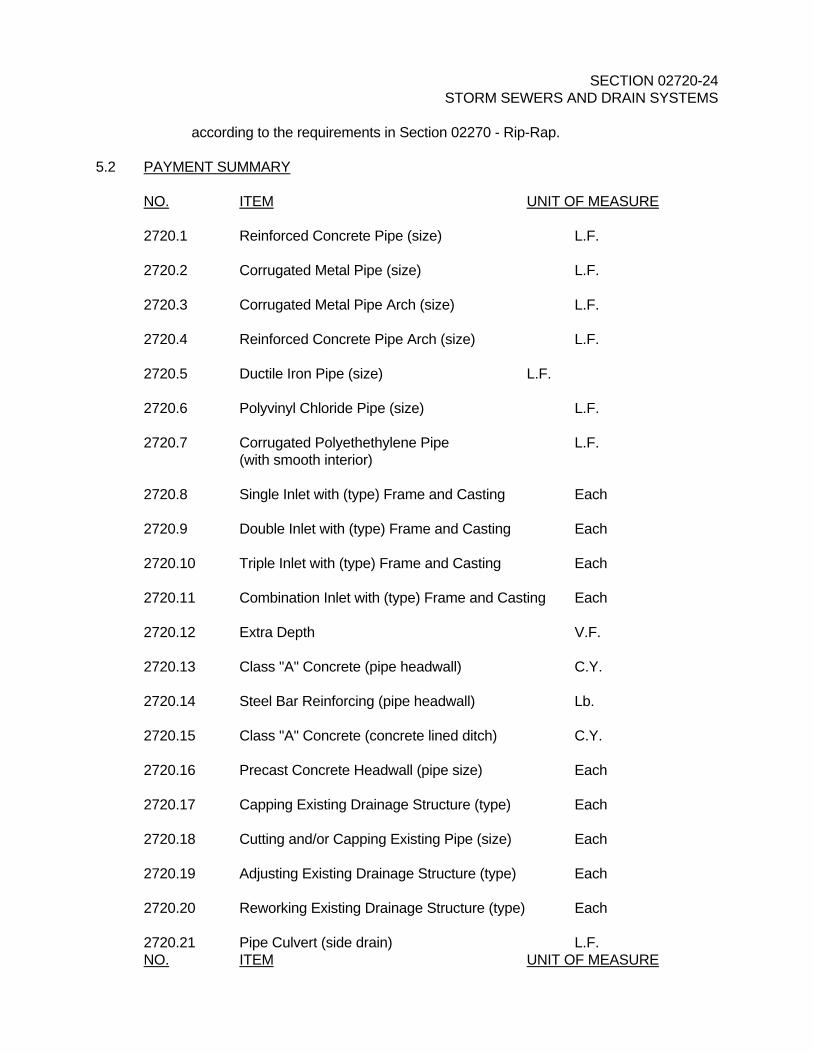
according to the requirements in Section 02270 - Rip-Rap. 5.2 PAYMENT SUMMARY NO. ITEM UNIT OF MEASURE 2720.1 Reinforced Concrete Pipe (size) L.F. 2720.2 Corrugated Metal Pipe (size) L.F. 2720.3 Corrugated Metal Pipe Arch (size) L.F. 2720.4 Reinforced Concrete Pipe Arch (size) L.F. 2720.5 Ductile Iron Pipe (size) L.F. 2720.6 Polyvinyl Chloride Pipe (size) L.F. 2720.7 Corrugated Polyethethylene Pipe L.F. (with smooth interior) 2720.8 Single Inlet with (type) Frame and Casting Each 2720.9 Double Inlet with (type) Frame and Casting Each 2720.10 Triple Inlet with (type) Frame and Casting Each 2720.11 Combination Inlet with (type) Frame and Casting Each 2720.12 Extra Depth V.F. 2720.13 Class "A" Concrete (pipe headwall) C.Y. 2720.14 Steel Bar Reinforcing (pipe headwall) Lb. 2720.15 Class "A" Concrete (concrete lined ditch) C.Y. 2720.16 Precast Concrete Headwall (pipe size) Each 2720.17 Capping Existing Drainage Structure (type) Each 2720.18 Cutting and/or Capping Existing Pipe (size) Each 2720.19 Adjusting Existing Drainage Structure (type) Each 2720.20 Reworking Existing Drainage Structure (type) Each 2720.21 Pipe Culvert (side drain) L.F. NO. ITEM UNIT OF MEASURE

SECTION 02720-25 STORM SEWERS AND DRAIN SYSTEMS 2720.22 Slope Drain L.F. 2720.23 Pipe Removed and Relaid (type) L.F. 2720.24 Pipe Drain L.F. 2720.25 Underdrain (type) L.F. 2720.26 Filter Cloth Underdrain (with or without pipe) L.F. 2720.27 Lateral Underdrain L.F. 2720.28 Lateral Endwall Each 2720.29 Perforated Pipe With Vertical Drain System L.F. 150 mm (six inch)
END OF SECTION - 02720