section 01 05 50 - project permits part 1 - general … filesection 01 05 50 - project permits part...
TRANSCRIPT
FLORIDA POWER & LIGHT FLAGLER SERVICE CENTER PROJECT PERMITS BRPH ARCHITECTS-ENGINEERS, INC.
C07084.006.00 01 05 50 - 1 05-16-16
SECTION 01 05 50 - PROJECT PERMITS
PART 1 - GENERAL
1.1 DESCRIPTION OF WORK A. The work outlined in this Section includes the providing of all labor, materials, and
services as required by Federal, State, and local codes. 1.2 RULES AND REGULATIONS
A. All contractors, subcontractors, and bidders providing services related to the
environment shall be held responsible for a level of competency with respect to the regulatory requirements within their area of expertise.
B. It shall be contingent on the Contractor and all Subcontractors to adhere to all such
legal requirements as mandated by the law, the permits, and/or the requirements of the applicable agencies. Further, it is contingent on the bidders to be aware of the requirements normally mandated by the approval agencies listed hereinafter and in turn, to provide a bid price sufficient to include all special requirements that could be required by the permitting agencies.
PART 2 - PRODUCTS (NOT USED) PART 3 - EXECUTION
3.1 PROJECT PERMITS A. The Contractor shall not begin construction of any portion of the general site water,
sewer, or stormwater system prior to receipt of all federal, state, and local construction permits as indicated in this section.
B. The Contractor shall be required to adhere to all requirements of the permits.
Included in adherence thereto is compliance with all conditions of the permit as well as requirements implied in the laws, ordinances, and regulations. The Contractor shall be responsible for payment of any fines from government agencies resulting from the Contractor's failure to adhere to all permit conditions and agency regulations. These shall include but not be limited to material and construction standards, environmental protection, certifications, notifications, and special conferences. The following permit applications have been or shall be made by the Owner to the agencies noted. Owner will pay for permits identified below in the following. Other required permits shall be the responsibility of the Contractor.

FLORIDA POWER & LIGHT FLAGLER SERVICE CENTER PROJECT PERMITS BRPH ARCHITECTS-ENGINEERS, INC.
C07084.006.00 01 05 50 - 2 05-16-16
AGENCY PERMIT Florida Department of Environmental Protection (FDEP)
Notice of Intent (NOI) to use Generic Permit for Stormwater Discharge from Large and Small Construction Activities (CGP)
FDEP FDEP FDEP
Notice of Intent to use the General Permit for Construction of Water Main Extensions for PWSs Notification/Application for constructing a Domestic Wastewater Collection/Transmission System National Pollutant Discharge Elimination System (NPDES) Stormwater Notice of Termination (NOT)
St. Johns River Water Management District (SJRWMD)
Standard General Environmental Resource Permit
City of Palm Coast City of Palm Coast
Site Plan Review Building Plan Review
3.2 PERMIT POSTING
A. The Owner shall make available to the Contractor upon issuance of the Notice to
Proceed copies of all permits with conditions related thereto. The Contractor shall post on a weatherproof display board all actual permits and keep, suitably accessible for use by the Owner, the Architect/Engineer, and representatives of the approval agencies, the actual permits and related materials such as drawings.
3.3 CONTRACTOR FURNISHED SYSTEMS A. Certain systems in the project, such as water and wastewater systems, are to be
furnished in compliance with the designs indicated. The designs indicated are not intended to be proprietary. It is contingent on the bidders marketing such systems in the State of Florida and the Contractors installing such systems to provide systems that are acceptable to the local utility authority as well as to the governmental agencies who approve the design shop drawings and accept the "As-Built" condition of the systems such as FDEP. If anytime during the construction process some portions of the systems prove to be unacceptable to the governmental agencies or the local utility authority, the systems shall be modified, corrected, or replaced until they are made acceptable. It shall be contingent on the contractor to propose only on systems that are acceptable to the local utility authority and the applicable governmental agencies. Further, it is contingent on the contractor and suppliers to be cognizant of pending regulatory changes that may affect this individual project and the systems to be furnished. The Contractor's responsibility on these systems will extend to that point when the actual systems are deemed acceptable to the applicable authority or agency. All
FLORIDA POWER & LIGHT FLAGLER SERVICE CENTER PROJECT PERMITS BRPH ARCHITECTS-ENGINEERS, INC.
C07084.006.00 01 05 50 - 3 05-16-16
submittals shall be made in the format required by the applicable authority or agency. Any changes or upgrades required shall be made at no expense to the Owner.
B. The water, sewer, and stormwater systems shall not be put into operation for
purposes other than testing for leaks and system functions prior to receipt of all required federal, state, and local agency clearance and operating permits.
3.4 CERTIFICATIONS/OPERATING PERMITS A. The following minimum certifications/operating permits are required prior to placing
the water, wastewater, and stormwater facilities into operation: 1. Potable Water System: FDEP "Certification of Construction Completion and
Request for Clearance to Place Permitted PWS Components into Operation.” 2. Stormwater System: Specific Water Management District approval of
"Statement of Completion As-Built Certification and Request to Transfer to Operation Entity."
3. Sanitary Sewer System: FDEP “Certification of Construction Completion and Request to Place Permitted SS Components into Operation”.
3.5 ENGINEER OF RECORD ATTENDANCES AT TESTING
A. The Engineer of Record (EOR) is required to certify to certain permitting agencies that the improvements have been constructed in substantial accordance with the permitted construction documents. The EOR must be satisfied that the improvements will function as intended and will not pose a threat to the health and welfare of the public. The EOR, or his/her designer, must be present to witness all facility water and sewer line leakage testing and lift station start-up testing. The Contractor shall notify the EOR a minimum of 48 hours prior to scheduled testing. If the testing is performed without notifying the EOR, a testing will be required with the EOR present at the Contractor’s expense.
3.6 FINAL CERTIFICATION
A. The Contractor shall provide to the Architect/Engineer "As-Built/Record" drawings, prepared by a surveyor licensed in the State of Florida, on all systems covered by the permits a minimum of sixty (60) days prior to building occupancy to allow for the Architect/Engineer to obtain the required final "As-Built/Record" acceptance, certification, and/or operating permits. In most cases including the water, wastewater and stormwater facilities, said agency acceptance will be required prior to occupancy of the facility or use of any part of the systems. The Contractor shall be advised that the use of unaccepted systems such as potable water systems, sanitary sewer systems, and those systems that would affect the health and safety of the employees of the Contractor, the Owner, or the public at large shall be at the risk of the Contractor. The Contractor shall use care in controlling and regulating the use of such systems. Any fines levied by the permitting agencies as the result of operating systems prior to agency acceptance shall be paid by the Contractor at no additional cost to the Owner.

FLORIDA POWER & LIGHT FLAGLER SERVICE CENTER PROJECT PERMITS BRPH ARCHITECTS-ENGINEERS, INC.
C07084.006.00 01 05 50 - 4 05-16-16
B. The Contractor shall submit the following information to the Engineer: 1. Potable Water System:
a. As-built/record drawings of the water distribution system, prepared and
signed and sealed by a surveyor licensed in the State of Florida. b. Satisfactory bacteriological results on the water distribution system
along with a plan indicating the location of the sampling. c. Letter certifying acceptable water main pressure testing.
2. Wastewater Collection/Transmission System:
a. As-Built/Record drawings of the wastewater collection/transmission
system, prepared and signed and sealed by a surveyor licensed in the State of Florida.
b. Letter certifying acceptable gravity sanitary sewer leakage testing. c. Letter certifying acceptable force main pressure / leakage testing. d. Lift station start-up reports. e. Lift station O&M manuals.
3. Stormwater System:
a. As-built/record drawings of stormwater facilities, prepared and signed
and sealed by a surveyor licensed in the State of Florida. C. The Contractor's project responsibility shall extend to the final acceptance and
issuance of operating permits by the approval agencies or authorities and in some cases could extend the time frame beyond that for final project acceptance.
3.7 SYSTEM SUBSTITUTIONS SUBSEQUENT TO PERMITTING A. If the Contractor proposes to substitute a system for use other than that detailed
and permitted by the Architect/Engineer, he shall provide the Owner’s Representative with all necessary supportive data required to file for a modification to the approved permit. In turn, the Contractor shall reimburse the Owner for all expenses incurred in the refiling of the applicable permit including, but not limited to, labor cost, reproduction cost, delivery charges, and filing fees. The Contractor should realize that this includes all items of a "substantial deviation" from the permitted project.
3.8 SCHEDULE IMPACT A. The Contractor shall provide all certifications and required material in such a time
frame as to not affect the completion date of the project. A minimum of sixty (60) days should be allowed from submission to the Architect/Engineer until acceptance of the systems by agencies such as FDEP and the applicable Water Management District. The Contractor's schedule shall reflect the "As-Builts/Record" conditions and certifications of all such systems and the Contractor shall perform all corrective measures mandated by the approval agencies.

FLORIDA POWER & LIGHT FLAGLER SERVICE CENTER PROJECT PERMITS BRPH ARCHITECTS-ENGINEERS, INC.
C07084.006.00 01 05 50 - 5 05-16-16
B. It shall be the Contractor's responsibility to flag the water system as "NON-POTABLE WATER" until written notice of FDEP clearance is issued; and/or to protect the system from contamination upon receipt of FDEP clearance. The Contractor's responsibility in this regard shall continue until the Owner provides written acceptance of the system.
C. Permits shall be listed on the regularly scheduled project meeting agenda for
update and discussion.
3.9 CONFERENCES A. The Contractor shall be aware of the requirements of the various agencies in the
State of Florida and all applicable government regulatory agencies that could require their attendance at a special agency or authority pre-construction conference. The Contractor shall set up all such meetings as required with attendance by a representative of the Owner or the Architect/Engineer. Further, the Contractor, who is deemed to be cognizant of the requirements of said agencies and authorities, shall provide at no additional expense any special requirements relating to labor, materials, or construction procedures.
3.10 MAINTENANCE OF TRAFFIC A. The Contractor shall be responsible for all around-the-clock maintenance of traffic
both on the site, as well as the adjoining roadways, as he affects such activities. This shall conform to all the applicable requirements of the City of Palm Bay, Brevard County, and the State of Florida Department of Transportation (FDOT). The Contractor shall submit a maintenance of traffic (MOT) plan to the Owner's Representative a minimum of forty-eight (48) hours in advance of work. The Contractor shall make all arrangements for inspection, layout, and safety review of the MOT in accordance with City, County and FDOT requirements as applicable.
3.11 SUBMITTALS AND TESTING A. The Contractor shall provide all necessary submittals such as shop drawings and
test reports as may be required by the utility authorities or permitting agencies.
3.12 "AS-BUILT/RECORD" DRAWINGS A. The Contractor shall provide upon completion of the work or portions thereof, "As-
Built/Record" drawings prepared by a surveyor licensed in the State of Florida, as required by and acceptable to all permitting agencies. Agencies require submittal from the Architect/Engineer of certified "As-Built/Record" drawings prior to placement of systems into service.
FLORIDA POWER & LIGHT FLAGLER SERVICE CENTER PROJECT PERMITS BRPH ARCHITECTS-ENGINEERS, INC.
C07084.006.00 01 05 50 - 6 05-16-16
B. It shall be the Contractor's responsibility to provide drawings in a timely manner and/or to accept responsibility for all agency monetary fines resulting from his failure to submit "As-Built/Record" drawings to the Architect/Engineer in a timely manner, or for his premature operation of a system prior to receipt of the system construction approval from the applicable agencies.
C. Following construction, a surveyor licensed in the State of Florida shall survey the
final construction as part of the site wide final as-built survey. The Contractor shall check this final as-built, make all necessary field changes, resurvey the affected areas, and submit the survey to the Architect/Engineer in separate submittals as required for the final certification to the applicable governmental agencies.
D. Utility “As-Built/Record” drawings (water, sewer, and stormwater) shall comply with
all requirements of the City of Palm Bay Engineering Department.
3.13 GOPHER TORTOISES
A. If any gopher tortoises or active gopher tortoise borrows are found located on the site prior to or during construction, construction shall cease immediately and the Contractor shall notify the Owner immediately.
B. The Owner shall make arrangements to have the gopher tortoises relocated.
3.14 SURFACE WATER QUALITY
A. Beside full adherence to the requirements of the Water Management District, the Contractor shall not discharge any stormwater runoff from the construction process off the project site. In the event that stormwater runoff from construction activities discharges off site, the Contractor shall be responsible for obtaining any permits required from EPA and paying any fines associated with non-compliance.
END OF SECTION 01 05 50

FLORIDA POWER & LIGHT FLAGLER SERVICE CENTER THRESHOLD BUILDING INSPECTION PLAN BRPH ARCHITECTS-ENGINEERS, INC.
C07084.006.00 01 05 60 - 1 05-16-16
SECTION 01 05 60 - THRESHOLD BUILDING INSPECTION PLAN
PART 1 - GENERAL
1.1 RELATED DOCUMENTS
A. Drawings and general provisions of the Contract, including General and Supplementary Conditions and Division 1 Specification Sections, apply to this Section.
B. This plan describes work required to comply with the Threshold Law, Chapter 553 of the Florida Statutes.
1.2 THE SPECIAL INSPECTOR
A. The Design-Builder shall hire the Special Inspector to inspect the construction of structural work and report that such work has been done in substantial compliance with the requirements of the official contract documents accepted by the Enforcing Agency, except variations permitted in writing by the Structural Engineer of Record.
1.3 THE OFFICIAL CONTRACT DOCUMENTS
A. Are defined as the plans, recorded addenda, project specifications including all referenced codes and standards, and this special inspection plan.
1.4 THE SPECIAL INSPECTOR IS NOT AUTHORIZED
A. To make design decisions, to alter contract requirements, direct Design-Builder's work, or be responsible for construction safety or Design-Builder’s or Contractor’s means and methods.
1.5 QUALIFICATIONS OF THE SPECIAL INSPECTOR
A. The Special Inspector shall be a Professional Engineer, currently registered in the State of Florida who has met the requirements of the Qualification Program for Special Inspectors. The Special Inspector shall have a minimum of seven (7) years of experience in the design and inspection of similar structures.
B. The Special Inspector may assign a qualified full-time employee to the project as his authorized technical representative. The authorized technical representative shall be a licensed architect, a licensed professional engineer, a graduate from an engineering education program in civil or structural engineering, a graduate from an architectural education program, an individual that has successfully completed an NCEES examination, a registered building inspector or a registered general contractor. The authorized technical representative shall be qualified for structural inspection by training and a minimum of one (1) year of experience in the
FLORIDA POWER & LIGHT FLAGLER SERVICE CENTER THRESHOLD BUILDING INSPECTION PLAN BRPH ARCHITECTS-ENGINEERS, INC.
C07084.006.00 01 05 60 - 2 05-16-16
inspection of similar structures, shall be acceptable to the Enforcing Agency, and shall exhibit knowledge in the structural materials and systems used in the project. Documentation of such training and experience shall be submitted to the Enforcing Agency for approval prior to commencement of inspection work.
1.6 RESPONSIBILITIES OF THE SPECIAL INSPECTOR
A. Thorough understanding of the official Contract Documents, including all amendments, knowledge of appropriate portions of governing building codes, and the exercise of common sense and good engineering judgment.
B. The Special Inspector shall provide a certified affidavit to the Owner and Structural Engineer of Record attesting that he has reviewed the Contract Documents and understands their content and the concept conveyed therein. Also, attesting that he has read the Threshold Building Inspection Plan, understands its content, and intends to comply with its requirements.
C. Timely and thorough inspection of all structural components.
D. Preparing reports and the preparation of field inspection reports for each inspection.
1.7 LIMITATIONS OF RESPONSIBILITIES OF THE SPECIAL INSPECTOR
A. The Special Inspector shall not function as a replacement for the Enforcing Agency nor shall he assume the responsibilities of the Structural Engineer of Record.
B. The presence of the Special Inspector does not alter or relieve the Contractor from his contractual and statutory obligation to comply with all requirements of the official Contract Documents and local building and safety codes. Deviations and unauthorized changes from the official Contract Documents remain the sole responsibility of the Contractor. The Special Inspector shall cooperate with the Contractor but shall not direct the Contractor’s work nor be responsible for construction means and methods.
C. The duties and responsibilities of the Special Inspector are limited to inspection and reporting on construction of structural components and all items included in this inspection plan.
D. Reports shall be limited to acknowledgment that structural components have been constructed in substantial conformance with the requirements of official Contract Documents or, if not in conformance, the location and description of variations. The Special Inspector is not to make design decisions or interpretations of the contract documents.
E. Special inspection does not include inspection, reporting, nor responsibility for glass components or frames; permanent or temporary metal or wood handrails; fire protection or fireproofing, roofing, architectural components, mechanical/plumbing/ electrical components, systems, or supports, architectural components, including architectural concrete, stone work, brick work, and other elements not contributing to the performance or capacity of the structural building frame.
FLORIDA POWER & LIGHT FLAGLER SERVICE CENTER THRESHOLD BUILDING INSPECTION PLAN BRPH ARCHITECTS-ENGINEERS, INC.
C07084.006.00 01 05 60 - 3 05-16-16
1.8 REPORTS
A. Shall be in electronic form and shall be completed at the end of the inspection or the period covered. Reports shall be maintained at all times on the jobsite in electronic form in chronological order. Reports shall be kept by the Special Inspector for a minimum of 7 years after the completion of the project.
1.9 VERBAL REPORTING
A. It is the duty of the Special Inspector to immediately notify the Contractor in person, and the Structural Engineer of Record by telephone, of the following: 1. The use of materials, tests, equipment, workmanship or construction not
conforming to the official contract documents. 2. Construction performed without inspection and not capable of being inspected
or tested in place. These exceptions shall then be issued electronically to those listed above and attached to the daily field reports.
B. The Special Inspector shall keep an exception file for follow-up. This file shall be reviewed on a daily basis and updated as exceptions are rectified. Any uncorrected exceptions shall be reported at an appropriate time, using a non-compliance notice, to the Contractor, Owner, Enforcing Agency, and Structural Engineer of Record.
1.10 SUBMITTALS
A. Inspection and daily reports shall be electronically submitted by the Special Inspector to the Owner, Enforcing Agency, Contractor, and Structural Engineer of Record, on a weekly basis.
B. If the special inspections are conducted by a duly authorized employee of the Special Inspector, the inspection reports, and daily reports shall be submitted to the Owner, Enforcing Agency, Structural Engineer of Record, and Contractor, signed by authorized representative and signed by the Special Inspector.
1.11 ITEMS AND CONTENTS OF REPORTS
A. Report number, date, time, weather including temperature, Contractor's representative present, description of type and location of work inspected, observations and remarks concerning compliance with contract documents.
B. Report of each as-built deviation or change from the requirements of the Contract Documents and/or approved shop drawings, including a report on corrective work required or performed.
C. Photographs as required for information and clarification.
FLORIDA POWER & LIGHT FLAGLER SERVICE CENTER THRESHOLD BUILDING INSPECTION PLAN BRPH ARCHITECTS-ENGINEERS, INC.
C07084.006.00 01 05 60 - 4 05-16-16
1.12 INTENT OF REPORTS
A. Reports are intended to notify the Owner, Enforcing Agency, Contractor, and Structural Engineer of Record of the following: 1. Work which is not being performed according to official Contract Documents. 2. Use of materials, equipment, or workmanship which does not conform to
requirements of official Contract Documents or which may result in improper and unacceptable work.
3. Recommend removal of nonconforming work or recommend corrective construction.
4. Recommendations for acceptance or rejection of work which is not capable of being inspected or tested.
5. Work performed and completed without being inspected or tested. 6. Requests for clarification.
1.13 FINAL REPORT
A. Final report shall be signed and sealed by the Special Inspector attesting as follows:
"To the best of my knowledge and belief, the reported construction of all structural
load bearing components complies with the requirements of the official Contract Documents and the shoring conforms with the shoring plans submitted to the Enforcing Agency.”
B. Final project report shall be prepared, signed and sealed by the Special Inspector and shall be submitted to the Owner, Enforcing Agency, Structural Engineer of Record, and Contractor.
1.14 CONTRACTOR REQUIREMENTS
A. The Contractor shall cooperate with and assist the Special Inspector in performing his inspection duties as specified herein. The Special Inspector shall have free access to the project at all times.
B. The Contractor shall advise the Special Inspector, in advance, of construction schedules and planned operations in order to assure timely and appropriate observation and inspection of items specified herein. The minimum notice given the Special Inspector shall be 24 hours prior to the time of the inspection. Further, the scheduled inspection time for reinforcing steel shall be not less than one hour prior to the scheduled concrete placement.
C. The Contractor shall furnish in a timely manner to the Special Inspector; copies of all reviewed and accepted submittals (excluding calculations) for the structural elements of the project.
FLORIDA POWER & LIGHT FLAGLER SERVICE CENTER THRESHOLD BUILDING INSPECTION PLAN BRPH ARCHITECTS-ENGINEERS, INC.
C07084.006.00 01 05 60 - 5 05-16-16
D. Special inspections do not relieve the Contractor of his responsibility to comply with the contract documents, any statutory or contractual obligations, nor his responsibilities to carry out his quality control inspections and testing. The Contractor has the sole responsibility for any deviations from the official contract documents and the costs of rectifying those deviations.
E. Work which is in non-compliance with the official contract documents may be corrected by the Contractor or the Contractor may submit to the Structural Engineer of Record a request for acceptance of the deviation.
F. Construction performed without inspection and that is unable to be inspected may require testing or removal as determined by the Structural Engineer of Record.
G. The Special Inspector cannot make the required completion statement and the building will not receive a Certificate of Occupancy if work is not in substantial accordance with the official contract documents or if construction is performed without inspection and is unable to be inspected.
H. Installation of all shoring and re-shoring shall be in accordance with the signed and sealed shoring and re-shoring drawings prepared by the delegated shoring Engineer. The delegated shoring Engineer or his authorized representative shall inspect and ensure that the drawing requirements and specifications are adhered to, and provide his written report to the Special Inspector prior to all concrete pours. The Special Inspector is to verify that the inspection is performed and is to observe that the work appears to be in compliance with the drawings.
1.15 REQUIREMENTS OF THE OWNER
A. The Owner shall arrange for all necessary contract documents, including two complete sets of architectural and structural documents for the project, including all drawings and specifications, the geotechnical report and materials test reports, to be furnished to the Special Inspector during the progress of the work in a timely manner. Provide the special inspector with two copies of all structural changes, revisions, addenda, etc.
B. The Owner shall ensure that the Contractor provides to the Enforcing Agency, Architect, Structural Engineer of Record, and the Special Inspector a shoring and re-shoring plan which is signed and sealed by a delegated Engineer registered in the State of Florida.
C. The Owner shall ensure that a qualified testing agency is retained. See contract documents for requirements.
D. The Owner shall ensure that a geotechnical consultant is retained to confirm that the specified foundation preparation is performed.
FLORIDA POWER & LIGHT FLAGLER SERVICE CENTER THRESHOLD BUILDING INSPECTION PLAN BRPH ARCHITECTS-ENGINEERS, INC.
C07084.006.00 01 05 60 - 6 05-16-16
PART 2 - PRODUCTS
2.1 CONTRACT DOCUMENTS
A. Structural Drawings and Specifications prepared by BRPH Architects • Engineers, Inc., latest revision.
2.2 STRUCTURAL SYSTEM DESCRIPTION
A. Deep Foundation: The deep foundations shall be precast concrete piles with concrete pile caps and grade beams.
B. Walls: The walls are composed of reinforced CMU, metal siding, and curtain wall.
C. Floors: Floor structures consist of post-tensioned slabs.
D. Roof: Roof framing consists of steel deck on joists and beams and post-tensioned concrete slabs.
PART 3 - EXECUTION
3.1 GENERAL
A. The following is a general inspection plan describing work to be performed by the Special Inspector. The intent is to describe minimum levels necessary to confirm that work complies with the design documents. The following are not inspector check lists but point out some critical areas requiring specific attention by the Special Inspector.
3.2 REINFORCED CONCRETE
A. The Contractor is to notify the Special Inspector a minimum of 24 hours prior to the placement of any structural concrete.
B. Reinforcing Steel: 1. Using the structural drawings, inspect grade, size, quantity, configuration and
spacing of reinforcing for compliance with the structural drawings supplemented with shop drawings. Prior to concrete placement report any noted conflict and confirm that corrections are made before concrete is poured.
2. Check minimum clearance requirements from concrete surfaces. 3. Check that reinforcing is adequately supported and tied to resist displacement
or shifting during pour. 4. Check that rebar surfaces are free of excess rust or other coatings that may
adversely affect bonding capacity. If oiling of forms is required, check that it is applied before reinforcing is placed.

FLORIDA POWER & LIGHT FLAGLER SERVICE CENTER THRESHOLD BUILDING INSPECTION PLAN BRPH ARCHITECTS-ENGINEERS, INC.
C07084.006.00 01 05 60 - 7 05-16-16
5. Check splice locations and required length of lap. Report any deviations from the contract documents before concrete is cast and confirm that corrections are made.
6. Check installation of hooked bars for compliance with the contract documents.
C. Check that expansion joint material, anchors, lifting inserts, and other embedded items are in compliance with the contract documents and approved shop drawings and have been positioned and secured in place so that displacement is not possible. 1. Check that conduits placed in the slab are reasonably spaced to ensure
integrity of the slab. 2. Confirm that load carrying embedded items are placed in compliance with the
contract documents. Relocation of embedded items in conflict with reinforcing will not be permitted without prior approval of the Structural Engineer of Record.
D. Check that construction joints, including dowels, keys and bulkheads, are in conformance with the contract documents. Review the location of construction joints in beams and slabs for compliance with the construction joint location plan submitted by the Contractor to the Structural Engineer of Record.
E. Openings: 1. Report all slab and wall openings larger than 12” and not shown on the
contract documents to the Architect/Engineer. Check placement of additional reinforcement around openings. No sleeves or openings will be permitted in beams without prior approval of the Structural Engineer of Record.
F. Check that all foreign material has been removed from spaces which concrete is to occupy.
G. The Special Inspector shall be on site when concrete is being placed as necessary to ascertain that proper concreting practices, as required by ACI 301, ASTM C94 and other recognized industry standards are followed. Observations by the Special Inspector shall include, but not be limited to, verification of the following: 1. Testing agency is on site and that mixing time, temperature, slump, and air
content are as specified. Check that addition of water to the concrete mix in the field is based on the guidelines set forth in the contract documents.
2. The concrete as delivered to the project site is as specified for that portion in which placement is to occur.
3. Concrete is being conveyed from mixer to place of final deposit by recognized industry standards. Concrete is being deposited continuously, or in layers of such thickness that no concrete will be deposited on concrete which has hardened sufficiently to cause the formation of seams or planes of weakness within the area of placement.
4. Concrete is being consolidated and thoroughly worked around reinforcement, embedded items and into corners of forms, eliminating air or stone pockets which may cause honeycombing, pitting or planes of weakness.
5. Curing procedures are as per contract documents, ACI 308, “Standard Practice for Curing Concrete” and other recognized industry standards.

FLORIDA POWER & LIGHT FLAGLER SERVICE CENTER THRESHOLD BUILDING INSPECTION PLAN BRPH ARCHITECTS-ENGINEERS, INC.
C07084.006.00 01 05 60 - 8 05-16-16
H. After the formwork has been removed, inspect concrete surfaces for honeycombing and voids.
3.3 STRUCTURAL STEEL
A. Inspect structural steel framing prior to concealment to verify grade, sizes, connections, straightness and finish. Check with contract documents and shop drawings.
B. Inspect setting of anchor bolts, embeds and other miscellaneous structural items prior to concreting. Verify size, quantity and finish.
C. Inspect Connections for the following: 1. Bolted connections: Type, size and number of bolts. Check that bolts are
clean and lubricated and have proper washers and that they conform to the specifications. Check that bolt holes are the specified type and size. Verify that bolts are properly tightened. For slip-critical bolts with load indicator washers, check all bolts visually and 10 percent with a feeler gauge.
2. Welded Connections: Verify that welders are AWS certified for the type of welds being made. Visually examine all welds for type, size and length for compliance with the structural drawings. Verify that required non-destructive testing is performed by the testing agency. Verify that welds are clean, free from slag, and that rust protection has been applied as per specifications.
D. Headed Stud Anchors: Check for size, length, spacing and welding.
E. Steel Decks: Check for type, size and gage. Check connection to supports.
F. Open Web Steel Joists:
1. Inspect steel joists to verify type, size, spacing, connections, straightness and finish. Inspect from construction documents and shop drawings.
2. Check that bearing conditions conform to requirements of S.J.I. and contract documents.
3. Verify that the temporary bracing and permanent cross-bridging are being implemented per requirements of the construction documents and erection drawings.
4. Inspect setting of shelf angles, bearing plates and miscellaneous structural items to verify size, quantity, location and finish.
5. Visually examine all field welds. Verify that welders are AWS certified.
3.4 MATERIALS TESTING
A. All testing requirements as defined in the contract documents shall be adhered to, with copies of results forwarded to the Special Inspector. Prior to each inspection, the Special Inspector shall review all material tests and report on their results. The Special Inspector may request the Design-Builder’s Representative to authorize additional tests if required by unforeseeable events or conditions. All materials testing must be executed by qualified laboratories and testing firms.
END OF SECTION 01 05 60

FLORIDA POWER & LIGHT FLAGLER SERVICE CENTER SUMMARY BRPH ARCHITECTS-ENGINEERS, INC.
C07084.006.00 01 10 00 - 1 05-16-16
SECTION 01 10 00 - SUMMARY
PART 1 - GENERAL
1.1 RELATED DOCUMENTS
A. Drawings and general provisions of the Contract, including General and Supplementary Conditions and other Division 01 Specification Sections, apply to this Section.
1.2 SUMMARY
A. Section Includes:
1. Project information. 2. Work covered by Contract Documents. 3. Phased construction. 4. Work by Owner. 5. Work under separate contracts. 6. Future work. 7. Purchase contracts. 8. Owner-furnished products. 9. Contractor-furnished, Owner-installed products. 10. Access to site. 11. Coordination with occupants. 12. Work restrictions. 13. Specification and drawing conventions. 14. Miscellaneous provisions.
B. Related Requirements:
1. Section 01 50 00 "Temporary Facilities and Controls" for limitations and procedures governing temporary use of Owner's facilities.
2. See Appendix B for Project Specific Requirements / Supplemental Conditions.
1.3 PROJECT INFORMATION
A. Project Identification:
1. Florida Power & Light Flagler Service Center 5910 E. Highway 100, Palm Coast, Florida 32164-2451 BRPH Project No. C07084.006.00

FLORIDA POWER & LIGHT FLAGLER SERVICE CENTER SUMMARY BRPH ARCHITECTS-ENGINEERS, INC.
C07084.006.00 01 10 00 - 2 05-16-16
B. Owner: Florida Power & Light, 700 Universe Boulevard, Juno, Florida 33408-2657.
1. Owner's Representative: Jon Rosenthal, Manager - Construction Florida Power and Light 561.694.4274 Office 561.310.1165 Mobile [email protected]
C. Architect: 1. BRPH Architects + Engineers, Inc. 5700 N. U.S. Highway 1 Suite 400 Melbourne, Florida 32940 321.254.7666
D. Architect's Consultants: The Architect has retained the following design professionals who have prepared designated portions of the Contract Documents:
1. Jezerinac Group – Structural Engineers
4400 PGA Boulevard Suite 306 Palm Beach Gardens, Florida 33410 561.622.8585
2. Jensen-Hughes – Fire Alarm/Fire Protection Engineers 725 Primera Boulevard Suite 215 Lake Mary, Florida 32746 407.647.3737
3. Kimley-Horn Associates, Inc. – Civil Engineers 1690 S. Congress Avenue Suite 100 Delray Beach, Florida 33445 561.404.7247
E. Contractor: To Be Determined through RFP.
1.4 WORK COVERED BY CONTRACT DOCUMENTS
A. The Work of Project is defined by the Contract Documents and consists of the following:
1. The Project Building consists of a Construction Type IIB, two-storey, hardened design, concrete tilt-wall building of 25,436 SF that is to serve the majority of the time as a Service Center Office Building (Occupancy Type B) for FP&L, and, shortly before, during and after a storm event, as a FP&L Emergency Operations Center (EOC).

FLORIDA POWER & LIGHT FLAGLER SERVICE CENTER SUMMARY BRPH ARCHITECTS-ENGINEERS, INC.
C07084.006.00 01 10 00 - 3 05-16-16
2. The Project Site consists of an existing FP&L property of approximately 257,000 SF/5.9 acres, with several existing structures, two of which are to be demolished. The site is to be redesigned to serve the new Service Center Building.
B. Type of Contract:
1. Project will be constructed under a single prime contract.
1.5 PHASED CONSTRUCTION
A. The Work shall be conducted in two phases, with each phase provisionally accepted as indicated in accordance with the Owner’s Procurement and Construction Contract.
1. Phase 1 – Entails the construction of the new Service Center office building and associated site improvements to operate and maintain the office building. The area and associated work included in Phase 1 is further defined in the Clearing and Demolition Plan C-05 and Phasing Plan Sheet C-06.01 and
2. Phase 2 – Entails the demolition of the existing Service Center office building and the applicable site improvements associated with the area around the existing office building. The area and associated work included in Phase 2 is further defined in the Clearing and Demolition Plan C-05, Phasing plan Sheet C-06.01 and Electrical Site Plan Sheets ES-103, ES-104 and ES-105.
B. Before commencing Work of each phase, submit an updated copy of Contractor's construction schedule showing the sequence, commencement and completion dates, and move-out and -in dates of Owner's personnel for all phases of the Work.
1.6 WORK BY OWNER
A. General: Cooperate fully with Owner so work may be carried out smoothly, without interfering with or delaying work under this Contract or work by Owner. Coordinate the Work of this Contract with work performed by Owner.
B. Preceding Work: Owner will perform the following construction operations at Project site. Those operations are scheduled to be provisionally accepted before work under this Contract begins.
1. Owner is proceeding with obtaining Water and Sewer, Power, and Communication (telephone and data) from the applicable providers in the area. Contracts are being negotiated and fees associated with providing the applicable service should be in place prior to the construction start.

FLORIDA POWER & LIGHT FLAGLER SERVICE CENTER SUMMARY BRPH ARCHITECTS-ENGINEERS, INC.
C07084.006.00 01 10 00 - 4 05-16-16
1.7 WORK UNDER SEPARATE CONTRACTS
A. General: Cooperate fully with separate contractors so work on those contracts may be carried out smoothly, without interfering with or delaying work under this Contract or other contracts. Coordinate the Work of this Contract with work performed under separate contracts.
B. Concurrent Work: Owner will perform the following construction operations at the Project Site. Those operations will be conducted simultaneously with work under this Contract.
1. Owner will be hiring separately, contractors to provide and install low voltage, audio visual equipment, security, furniture and communication (communication, radio, and data) system for use in the new building. This work will be done in cooperation and simultaneously with the Contractors work. Furthermore, Owner will have a separate contractor relocate the 2 fuel tanks and Test Shed located in the Phase 2 area of the Project. The completion of this work will need to be coordinated with the Contractors work.
2. Additionally, it should be noted that the site is and will remain an active FPL Service Center with staff, deliveries, operations, etc. occurring around the clock. The facility and its operations will need to remain operational throughout the project
C. Subsequent Work: Owner will perform the following additional work at site after the completion of Phase 2. Completion of this work will depend on successful completion and preparatory work under this Contract.
1. Owner will be installing wooden utility poles and other equipment in the Green Space identified on Sheet C-06 at the completion of Phase 2. The utility poles and equipment to be located in this Green Space are to be used for training and the establishment of a new Training Area for the staff located at the Site.
1.8 PURCHASE CONTRACTS
A. General: Owner has negotiated purchase contracts with suppliers of material and equipment to be incorporated into the Work. Owner will assign these purchase contracts to Contractor. Include receiving, handling, storage if required, and installation of material and equipment in the Contract Sum, unless otherwise indicated.
1. Contractor's responsibilities are same as if Contractor had negotiated purchase contracts, including responsibility to renegotiate purchase and to execute final purchasing agreements.
B. Purchase Contracts Information:
1. Owner will be purchasing the proposed stand-by Emergency Generator, Fuel Tank, and metal protective housing surrounding the Emergency Generator. Owner will purchase and provide the equipment including the load bank test and warranty on the equipment provided for the Contractor to install. Contractor shall be responsible for coordinating the receipt, handling, storage
FLORIDA POWER & LIGHT FLAGLER SERVICE CENTER SUMMARY BRPH ARCHITECTS-ENGINEERS, INC.
C07084.006.00 01 10 00 - 5 05-16-16
if required, complete installation and start up including one initial supply of fuel for the fuel tank. The Contractor shall be responsible for providing the applicable fuel to fill the emergency generator fuel tank one time in connection with the installation and start-up of the equipment. Owner shall be responsible for refueling the tank after the initial fuel supplied is exhausted and the load bank test is complete.
1.9 OWNER-FURNISHED PRODUCTS
A. Owner will furnish products indicated. The Work includes receiving, unloading, handling, storing, protecting, and installing Owner-furnished products[ and making building services connections].
B. Owner-Furnished Products:
1. Low voltage cabling, Audio Visual, Furniture, Security, Appliances, etc.
1.10 ACCESS TO SITE
A. Use of Site: Limit use of Project site to areas within the Contract limits indicated. Do not disturb portions of Project site beyond areas in which the Work is indicated.
1. Limits: Confine construction operations to areas defined in the Phasing Plan. 2. Driveways, Walkways and Entrances: Keep driveways, loading areas and
entrances serving premises clear and available to Owner, Owner's employees, and emergency vehicles at all times. Do not use these areas for parking or storage of materials.
a. Schedule deliveries to minimize use of driveways and entrances by construction operations.
b. Schedule deliveries to minimize space and time requirements for storage of materials and equipment on-site.
1.11 COORDINATION WITH OCCUPANTS
A. Partial Owner Occupancy: Owner will occupy the premises during entire construction period, with the exception of areas under construction. Cooperate with Owner during construction operations to minimize conflicts and facilitate Owner usage. Perform the Work so as not to interfere with Owner's operations. Maintain existing exits unless otherwise indicated.
1. Maintain access to existing walkways, corridors, and other adjacent occupied or used facilities. Do not close or obstruct walkways, corridors, or other occupied or used facilities without written permission from Owner and authorities having jurisdiction.
2. Provide not less than 72 hours' notice to Owner of activities that will affect Owner's operations.
FLORIDA POWER & LIGHT FLAGLER SERVICE CENTER SUMMARY BRPH ARCHITECTS-ENGINEERS, INC.
C07084.006.00 01 10 00 - 6 05-16-16
B. Owner Limited Occupancy of Completed Areas of Construction: Owner reserves the right to occupy and to place and install equipment in completed portions of the Work, prior to Provisional Acceptance (per the Owner’s Contract) of the Work, provided such occupancy does not interfere with completion of the Work. Such placement of equipment and limited occupancy shall not constitute acceptance of the total Work.
1. Architect will prepare a Certificate of Provisional Acceptance (per the Owner’s Contract) for each specific portion of the Work to be occupied prior to Owner acceptance of the completed Work.
2. Obtain a Certificate of Occupancy from authorities having jurisdiction before limited Owner occupancy.
3. Before limited Owner occupancy, mechanical and electrical systems shall be fully operational, and required tests and inspections shall be successfully completed. On occupancy, Owner will operate and maintain mechanical and electrical systems serving occupied portions of Work.
4. On occupancy, Owner will assume responsibility for maintenance and custodial service for occupied portions of Work.
1.12 WORK RESTRICTIONS
A. Work Restrictions, General: Comply with restrictions on construction operations.
1. Comply with limitations on use of public streets and with other requirements of authorities having jurisdiction.
B. On-Site Work Hours: Limit work in the existing building to normal business working hours of 7:00 a.m. to 5:00 p.m., Monday through Friday, unless otherwise indicated.
1. Weekend Hours: Hours to be coordinated with Owner. 2. Early Morning Hours: Hours to be coordinated with Owner. 3. Hours for Utility Shutdowns: Hours to be coordinated with Owner. 4. Hours for Core Drilling: Hours to be coordinated with Owner.
C. Existing Utility Interruptions: Do not interrupt utilities serving facilities occupied by Owner or others unless permitted under the following conditions and then only after providing temporary utility services according to requirements indicated:
1. Notify Architect and Owner not less than 48 hours in advance of proposed utility interruptions.
D. Noise, Vibration, and Odors: Coordinate operations that may result in high levels of noise and vibration, odors, or other disruption to Owner occupancy with Owner.
1. Notify Architect and Owner not less than 48 hours in advance of proposed disruptive operations.
E. Controlled Substances: Use of tobacco products and other controlled substances on Project site is not permitted.
FLORIDA POWER & LIGHT FLAGLER SERVICE CENTER SUMMARY BRPH ARCHITECTS-ENGINEERS, INC.
C07084.006.00 01 10 00 - 7 05-16-16
F. Employee Identification: Provide identification tags for Contractor personnel working on Project site. Require personnel to use identification tags at all times.
G. Employee Screening: Comply with Owner's requirements for drug and background screening of Contractor personnel working on Project site.
1. Maintain list of approved screened personnel with Owner's representative.
1.13 SPECIFICATION AND DRAWING CONVENTIONS
A. Specification Content: The Specifications use certain conventions for the style of language and the intended meaning of certain terms, words, and phrases when used in particular situations. These conventions are as follows:
1. Imperative mood and streamlined language are generally used in the Specifications. The words "shall," "shall be," or "shall comply with," depending on the context, are implied where a colon (:) is used within a sentence or phrase.
2. Specification requirements are to be performed by Contractor unless specifically stated otherwise.
B. Division 01 General Requirements: Requirements of Sections in Division 01 apply to the Work of all Sections in the Specifications.
C. Drawing Coordination: Requirements for materials and products identified on Drawings are described in detail in the Specifications. One or more of the following are used on Drawings to identify materials and products:
1. Terminology: Materials and products are identified by the typical generic terms used in the individual Specifications Sections.
2. Abbreviations: Materials and products are identified by abbreviations scheduled on Drawings.
3. Keynoting: Materials and products are identified by reference keynotes referencing Specification Section numbers found in this Project Manual.
PART 2 - PRODUCTS (Not Used)
PART 3 - EXECUTION (Not Used)
END OF SECTION 01 10 00

THIS PAGE INTENTIONALLY LEFT BLANK
FLORIDA POWER & LIGHT FLAGLER SERVICE CENTER MULTIPLE CONTRACT SUMMARY BRPH ARCHITECTS-ENGINEERS, INC.
C07084.006.00 01 12 00 - 1 05-16-16
SECTION 01 12 00 - MULTIPLE CONTRACT SUMMARY
PART 1 - GENERAL
1.1 RELATED DOCUMENTS
A. Drawings and general provisions of the Contract, including General and Supplementary Conditions and other Division 01 Specification Sections, apply to this Section.
1.2 SUMMARY
A. Section includes a summary of each contract, including responsibilities for coordination and temporary facilities and controls.
B. Specific requirements for Work of each contract are also indicated in individual Specification Sections and on Drawings.
C. Related Requirements:
1. Section 01 10 00 "Summary" for the Work covered by the Contract Documents, restrictions on use of Project site, phased construction, coordination with occupants, and work restrictions.
2. Section 01 31 00 "Project Management and Coordination" for general coordination requirements.
1.3 DEFINITIONS
A. Permanent Enclosure: As determined by Architect, the condition at which roofing is insulated and weathertight; exterior walls are insulated and weathertight; and all openings are closed with permanent construction or substantial temporary closures equivalent in weather protection to permanent construction.
1.4 COORDINATION ACTIVITIES
A. Coordination activities of Owner’s Representative include, but are not limited to, the following:
1. Provide overall coordination of the Work. 2. Coordinate shared access to work areas. 3. Coordinate product selections for compatibility. 4. Provide overall coordination of temporary facilities and controls. 5. Coordinate, schedule, and approve interruptions of permanent and temporary
utilities, including those necessary to make connections for temporary services.

FLORIDA POWER & LIGHT FLAGLER SERVICE CENTER MULTIPLE CONTRACT SUMMARY BRPH ARCHITECTS-ENGINEERS, INC.
C07084.006.00 01 12 00 - 2 05-16-16
6. Coordinate construction and operations of the Work with work performed by each Contract, Owner's construction forces and any separate contracts.
7. Prepare Coordination Drawings in collaboration with each subcontractor to coordinate work by more than one contract.
8. Coordinate sequencing and scheduling of the Work. Include the following:
a. Initial Coordination Meeting: At earliest possible date, arrange and conduct a meeting with subcontractors for sequencing and coordinating the Work; negotiate reasonable adjustments to schedules.
b. Prepare a combined subcontractors' construction schedule for entire Project. Base schedule on preliminary construction schedule. Secure time commitments for performing critical construction activities from subcontractors. Show activities of each subcontract on a separate sheet. Prepare a simplified summary sheet indicating combined construction activities of subcontracts.
1) Submit schedules for approval. 2) Distribute copies of approved schedules to subcontractors.
9. Provide weekly photographic documentation. 10. Provide quality-assurance and quality-control services specified in
Section 01 40 00 "Quality Requirements." 11. Coordinate sequence of activities to accommodate tests and inspections, and
coordinate schedule of tests and inspections. 12. Provide information necessary to adjust, move or relocate existing utility
structures affected by construction. 13. Locate existing permanent benchmarks, control points and similar reference
points, and establish permanent benchmarks on Project site. 14. Provide field surveys of in-progress construction and site work and final
property survey. 15. Provide progress cleaning of common areas and coordinate progress cleaning
of areas or pieces of equipment where more than one subcontractor has worked.
16. Coordinate cutting and patching. 17. Coordinate protection of the Work. 18. Coordinate firestopping. 19. Coordinate completion of interrelated punch list items. 20. Coordinate preparation of Project Record Documents if information from more
than one subcontractor is to be integrated with information from other subcontractors to form one combined record.
21. Print and submit Record Documents if installations by more than one subcontractor are indicated on the same contract drawing or shop drawing.
22. Collect record Specification Sections from subcontractors, collate Sections into numeric order, and submit complete set.
B. Responsibilities of Owner’s Representative for temporary facilities and controls include, but are not limited to, the following:
1. Provide common-use field office for use by all personnel engaged in construction activities.
2. Provide telephone service for common-use facilities.
FLORIDA POWER & LIGHT FLAGLER SERVICE CENTER MULTIPLE CONTRACT SUMMARY BRPH ARCHITECTS-ENGINEERS, INC.
C07084.006.00 01 12 00 - 3 05-16-16
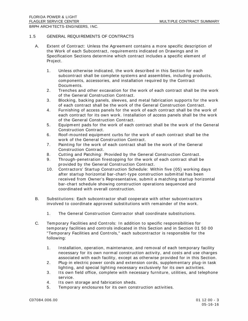
1.5 GENERAL REQUIREMENTS OF CONTRACTS
A. Extent of Contract: Unless the Agreement contains a more specific description of the Work of each Subcontract, requirements indicated on Drawings and in Specification Sections determine which contract includes a specific element of Project.
1. Unless otherwise indicated, the work described in this Section for each subcontract shall be complete systems and assemblies, including products, components, accessories, and installation required by the Contract Documents.
2. Trenches and other excavation for the work of each contract shall be the work of the General Construction Contract.
3. Blocking, backing panels, sleeves, and metal fabrication supports for the work of each contract shall be the work of the General Construction Contract.
4. Furnishing of access panels for the work of each contract shall be the work of each contract for its own work. Installation of access panels shall be the work of the General Construction Contract.
5. Equipment pads for the work of each contract shall be the work of the General Construction Contract.
6. Roof-mounted equipment curbs for the work of each contract shall be the work of the General Construction Contract.
7. Painting for the work of each contract shall be the work of the General Construction Contract.
8. Cutting and Patching: Provided by the General Construction Contract. 9. Through-penetration firestopping for the work of each contract shall be
provided by the General Construction Contract. 10. Contractors' Startup Construction Schedule: Within five (05) working days
after startup horizontal bar-chart-type construction submittal has been received from Owner’s Representative, submit a matching startup horizontal bar-chart schedule showing construction operations sequenced and coordinated with overall construction.
B. Substitutions: Each subcontractor shall cooperate with other subcontractors involved to coordinate approved substitutions with remainder of the work.
1. The General Construction Contractor shall coordinate substitutions.
C. Temporary Facilities and Controls: In addition to specific responsibilities for temporary facilities and controls indicated in this Section and in Section 01 50 00 "Temporary Facilities and Controls," each subcontractor is responsible for the following:
1. Installation, operation, maintenance, and removal of each temporary facility necessary for its own normal construction activity, and costs and use charges associated with each facility, except as otherwise provided for in this Section.
2. Plug-in electric power cords and extension cords, supplementary plug-in task lighting, and special lighting necessary exclusively for its own activities.
3. Its own field office, complete with necessary furniture, utilities, and telephone service.
4. Its own storage and fabrication sheds. 5. Temporary enclosures for its own construction activities.

FLORIDA POWER & LIGHT FLAGLER SERVICE CENTER MULTIPLE CONTRACT SUMMARY BRPH ARCHITECTS-ENGINEERS, INC.
C07084.006.00 01 12 00 - 4 05-16-16
6. Staging and scaffolding for its own construction activities. 7. General hoisting facilities for its own construction activities, up to 2 tons. 8. Waste disposal facilities, including collection and legal disposal of its own
hazardous, dangerous, unsanitary, or other harmful waste materials. 9. Progress cleaning of work areas affected by its operations on a daily basis. 10. Secure lockup of its own tools, materials, and equipment. 11. Construction aids and miscellaneous services and facilities necessary
exclusively for its own construction activities.
D. Temporary Heating, Cooling, and Ventilation: The General Construction Contractor is responsible for temporary heating, cooling, and ventilation, including utility-use charges, temporary meters, and temporary connections.
E. Temporary Heating, Cooling, and Ventilation: The General Construction Contractor is responsible for temporary heating, cooling, and ventilation before weathertight enclosure of building is complete. The General Construction Contractor is also responsible for temporary heating, cooling, and ventilation after permanent enclosure of building is complete.
F. Use Charges: Comply with the following:
1. Sewer Service: Include the cost for sewer service use by all parties engaged in construction activities at Project site in the General Construction Contract.
2. Water Service: Include the cost for water service, whether metered or otherwise, for water used by all entities engaged in construction activities at Project site in the General Construction Contract.
3. Electric Power Service: Include the cost for electric power service, whether metered or otherwise, for electricity used by all entities engaged in construction activities at Project site in the General Construction Contract.
1.6 GENERAL CONSTRUCTION CONTRACT
A. Work in the General Construction Contract includes, but is not limited to, the following:
1. Remaining work not identified as work under other contracts. 2. Site preparation, including clearing, building demolition and relocations, and
earthwork. 3. Site improvements, including roadways, parking lots, pedestrian paving, site
development furnishings and equipment, and landscaping. 4. Tunnels for site utilities. 5. Selective demolition. 6. Foundations, including footings, foundation walls and piles. 7. Slabs-on-grade, including earthwork, sub-drainage systems, and insulation. 8. Below-grade building construction, including excavation, backfill, and thermal
and moisture protection. 9. Superstructure, including floor and roof construction, and any sprayed fire-
resistive materials and/or board fire protection. 10. Exterior closure, including walls, parapets, doors, windows and louvers. 11. Roofing, including coverings, flashings and roof specialties.

FLORIDA POWER & LIGHT FLAGLER SERVICE CENTER MULTIPLE CONTRACT SUMMARY BRPH ARCHITECTS-ENGINEERS, INC.
C07084.006.00 01 12 00 - 5 05-16-16
12. Interior construction, including partitions, doors, interior glazed openings and fittings.
13. Fire-protection specialties. 14. Stairs, including railings and finishes. 15. Interior finishes, finish carpentry, architectural woodwork and built-in
casework. 16. Miscellaneous items, including concrete equipment bases and painting of
mechanical and electrical work. 17. Conveying systems, including elevators. 18. Equipment, including the following:
a. Restroom accessories b. Toilet partitions c. Projection screens. d. Residential appliances.
19. Furnishings, including fixed/built-in casework and window treatments. 20. Special construction, including the following:
a. Pre-engineered structures. b. Special-purpose rooms.
B. Temporary facilities and controls in the General Construction Contract include, but are not limited to, the following:
1. Temporary facilities and controls that are not otherwise specifically assigned to the HVAC Subcontractor, Electrical Subcontractor and/or Plumbing Subcontractor.
2. Sediment and erosion control. 3. Unpiped sewers and drainage, including drainage ditches, dry wells,
stabilization ponds, and containers. 4. Stormwater control. 5. Unpiped temporary toilet fixtures, wash facilities, and drinking water facilities,
including disposable supplies. 6. Temporary enclosure for building exterior, except as indicated. 7. Temporary roads and paved areas. 8. Dewatering facilities and drains. 9. Excavation support and protection, unless required solely for the Work of
another contract. 10. Special or unusual hoisting requirements for construction activities, including
hoisting loads in excess of 2 tons, hoisting material or equipment into spaces below grade, and hoisting requirements outside building enclosure.
11. Project identification and temporary signs. 12. General waste disposal facilities. 13. Pest control. 14. Temporary stairs. 15. Temporary fire-protection facilities. 16. Barricades, warning signs, and lights. 17. Site enclosure fence. 18. Covered walkways. 19. Security enclosure and lockup. 20. Environmental protection.

FLORIDA POWER & LIGHT FLAGLER SERVICE CENTER MULTIPLE CONTRACT SUMMARY BRPH ARCHITECTS-ENGINEERS, INC.
C07084.006.00 01 12 00 - 6 05-16-16
21. Restoration of Owner's existing facilities used as temporary facilities.
1.7 PLUMBING CONTRACT
A. Work in the Plumbing Contract includes, but is not limited to, the following:
1. Site water supply and distribution. 2. Site sanitary sewerage. 3. Site storm drainage. 4. Site fuel distribution. 5. Site special plumbing systems. 6. Plumbing fixtures. 7. Domestic water distribution. 8. Sanitary waste. 9. Stormwater drainage. 10. Special plumbing systems, including the following, as may be applicable:
a. Compressed air. b. Deionized water. c. Distilled water. d. Fuel oil. e. Natural gas. f. Medical gas. g. Vacuum. h. Acid waste. i. Pools and fountains.
11. Fire-suppression systems. 12. Special fire-suppression systems, including the following:
a. Foam fire-extinguishing systems. b. Clean-agent extinguishing systems.
13. Plumbing connections to equipment furnished by others.
B. Temporary facilities and controls in the Plumbing Contract include, but are not limited to, the following:
1. Piped sewerage and drainage. 2. Piped gas service. 3. Piped water service. 4. Piped temporary toilet fixtures, wash facilities, and drinking water facilities. 5. Plumbing connections to existing systems and temporary facilities and
controls furnished by others.
1.8 HVAC CONTRACT
A. Work in the HVAC Contract includes, but is not limited to, the following:
1. HVAC systems and equipment.
FLORIDA POWER & LIGHT FLAGLER SERVICE CENTER MULTIPLE CONTRACT SUMMARY BRPH ARCHITECTS-ENGINEERS, INC.
C07084.006.00 01 12 00 - 7 05-16-16
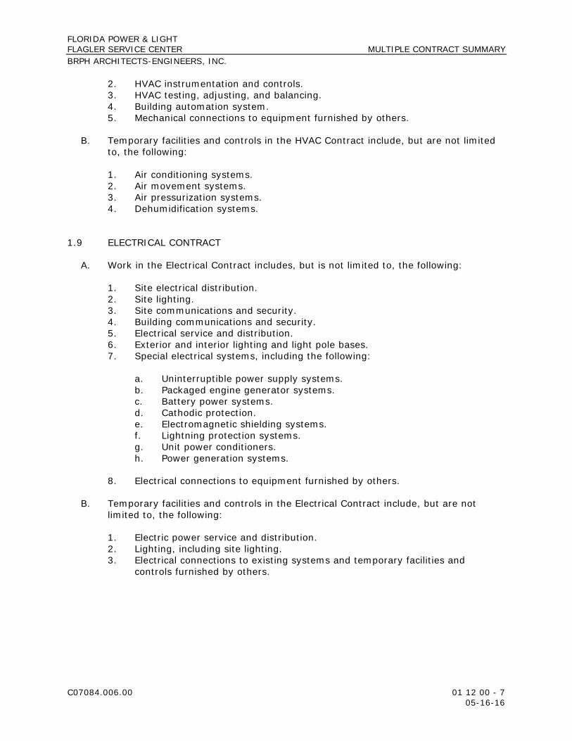
2. HVAC instrumentation and controls. 3. HVAC testing, adjusting, and balancing. 4. Building automation system. 5. Mechanical connections to equipment furnished by others.
B. Temporary facilities and controls in the HVAC Contract include, but are not limited to, the following:
1. Air conditioning systems. 2. Air movement systems. 3. Air pressurization systems. 4. Dehumidification systems.
1.9 ELECTRICAL CONTRACT
A. Work in the Electrical Contract includes, but is not limited to, the following:
1. Site electrical distribution. 2. Site lighting. 3. Site communications and security. 4. Building communications and security. 5. Electrical service and distribution. 6. Exterior and interior lighting and light pole bases. 7. Special electrical systems, including the following:
a. Uninterruptible power supply systems. b. Packaged engine generator systems. c. Battery power systems. d. Cathodic protection. e. Electromagnetic shielding systems. f. Lightning protection systems. g. Unit power conditioners. h. Power generation systems.
8. Electrical connections to equipment furnished by others.
B. Temporary facilities and controls in the Electrical Contract include, but are not limited to, the following:
1. Electric power service and distribution. 2. Lighting, including site lighting. 3. Electrical connections to existing systems and temporary facilities and
controls furnished by others.

FLORIDA POWER & LIGHT FLAGLER SERVICE CENTER MULTIPLE CONTRACT SUMMARY BRPH ARCHITECTS-ENGINEERS, INC.
C07084.006.00 01 12 00 - 8 05-16-16
PART 2 - PRODUCTS (Not Used)
PART 3 - EXECUTION (Not Used)
END OF SECTION 01 12 00

FLORIDA POWER & LIGHT FLAGLER SERVICE CENTER ALTERNATES BRPH ARCHITECTS-ENGINEERS, INC.
C07084.006.00 01 23 00 - 1 05-16-16
SECTION 01 23 00 - ALTERNATES
PART 1 - GENERAL
1.1 RELATED DOCUMENTS
A. Drawings and general provisions of the Contract, including General and Supplementary Conditions and other Division 01 Specification Sections, apply to this Section.
1.2 SUMMARY
A. Section includes administrative and procedural requirements for alternates.
1.3 DEFINITIONS
A. Alternate: An amount proposed by bidders and stated on the Bid Form for certain work defined in the bidding requirements that may be added to or deducted from the base bid amount if Owner decides to accept a corresponding change either in the amount of construction to be completed or in the products, materials, equipment, systems, or installation methods described in the Contract Documents.
1. Alternates described in this Section are part of the Work only if enumerated in the Agreement.
2. The cost or credit for each alternate is the net addition to or deduction from the Contract Sum to incorporate alternate into the Work. No other adjustments are made to the Contract Sum.
1.4 PROCEDURES
A. Coordination: Revise or adjust affected adjacent work as necessary to completely integrate work of the alternate into Project.
1. Include as part of each alternate, miscellaneous devices, accessory objects, and similar items incidental to or required for a complete installation whether or not indicated as part of alternate.
B. Notification: Immediately following award of the Contract, notify each party involved, in writing, of the status of each alternate. Indicate if alternates have been accepted, rejected, or deferred for later consideration. Include a complete description of negotiated revisions to alternates.
C. Execute accepted alternates under the same conditions as other work of the Contract.

FLORIDA POWER & LIGHT FLAGLER SERVICE CENTER ALTERNATES BRPH ARCHITECTS-ENGINEERS, INC.
C07084.006.00 01 23 00 - 2 05-16-16
D. Schedule: A schedule of alternates is included at the end of this Section. Specification Sections referenced in schedule contain requirements for materials necessary to achieve the work described under each alternate.
PART 2 - PRODUCTS (Not Used)
PART 3 - EXECUTION
3.1 SCHEDULE OF ALTERNATES
A. Contractor may provide Alternates for specified work; Owner reserves the right to accept or reject proposed alternate.
END OF SECTION 01 23 00

FLORIDA POWER & LIGHT FLAGLER SERVICE CENTER SUBSTITUTION PROCEDURES BRPH ARCHITECTS-ENGINEERS, INC.
C07084.006.00 01 25 00 - 1 05-16-16
SECTION 01 25 00 - SUBSTITUTION PROCEDURES
PART 1 - GENERAL
1.1 RELATED DOCUMENTS
A. Drawings and general provisions of the Contract, including General and Supplementary Conditions and other Division 01 Specification Sections, apply to this Section.
1.2 SUMMARY
A. Section includes administrative and procedural requirements for substitutions.
B. Related Requirements:
1. Section 01 21 00 "Allowances" for products selected under an allowance. 2. Section 01 23 00 "Alternates" for products selected under an alternate. 3. Section 01 60 00 "Product Requirements" for requirements for submitting
comparable product submittals for products by listed manufacturers.
1.3 DEFINITIONS
A. Substitutions: Changes in products, materials, equipment, and methods of construction from those required by the Contract Documents and proposed by Contractor.
1. Substitutions for Cause: Changes proposed by Contractor that are required due to changed Project conditions, such as unavailability of product, regulatory changes, or unavailability of required warranty terms.
2. Substitutions for Convenience: Changes proposed by Contractor or Owner that are not required in order to meet other Project requirements but may offer time- and/or cost-saving advantages to Owner.
1.4 ACTION SUBMITTALS
A. Substitution Requests: Submit three copies of each request for consideration. Identify product or fabrication or installation method to be replaced. Include Specification Section number and title and Drawing numbers and titles.
1. Substitution Request Form: Use CSI Form 13.1A, a copy of which follows this section.
2. Documentation: Show compliance with requirements for substitutions and the following, as applicable:
a. Statement indicating why specified product or fabrication or installation cannot be provided, if applicable.

FLORIDA POWER & LIGHT FLAGLER SERVICE CENTER SUBSTITUTION PROCEDURES BRPH ARCHITECTS-ENGINEERS, INC.
C07084.006.00 01 25 00 - 2 05-16-16
b. Coordination information, including a list of changes or revisions needed to other parts of the Work and to construction performed by Owner and separate subcontractors that will be necessary to accommodate proposed substitution.
c. Detailed comparison of significant qualities of proposed substitution with those of the Work specified. Include annotated copy of applicable Specification Section. Significant qualities may include attributes such as performance, weight, size, durability, visual effect, sustainable design characteristics, warranties, and specific features and requirements indicated. Indicate deviations, if any, from the Work specified.
d. Product Data, including drawings and descriptions of products and fabrication and installation procedures.
e. Samples, where applicable or requested. f. Certificates and qualification data, where applicable or requested. g. List of similar installations for completed projects with project names
and addresses and names and addresses of architects and owners. h. Material test reports from a qualified testing agency indicating and
interpreting test results for compliance with requirements indicated. i. Research reports evidencing compliance with building code in effect for
Project, from 2014 Florida Building Code, 5th Edition. j. Detailed comparison of Contractor's construction schedule using
proposed substitution with products specified for the Work, including effect on the overall Contract Time. If specified product or method of construction cannot be provided within the Contract Time, include letter from manufacturer, on manufacturer's letterhead, stating date of receipt of purchase order, lack of availability, or delays in delivery.
k. Cost information, including a proposal of change, if any, in the Contract Sum.
l. Contractor's certification that proposed substitution complies with requirements in the Contract Documents except as indicated in substitution request, is compatible with related materials, and is appropriate for applications indicated.
m. Contractor's waiver of rights to additional payment or time that may subsequently become necessary because of failure of proposed substitution to produce indicated results.
3. Architect's Action: If necessary, Architect will request additional information or documentation for evaluation within seven (07) calendar days of receipt of a request for substitution. Architect will notify Contractor of acceptance or rejection of proposed substitution within 15 calendar days of receipt of request, or seven (07) calendar days of receipt of additional information or documentation, whichever is later.
a. Forms of Acceptance: Change Order, Construction Change Directive (CCD), or Architect's Supplemental Instructions (ASI) for minor changes in the Work.
b. Use product specified if Architect does not issue a decision on use of a proposed substitution within time allocated.

FLORIDA POWER & LIGHT FLAGLER SERVICE CENTER SUBSTITUTION PROCEDURES BRPH ARCHITECTS-ENGINEERS, INC.
C07084.006.00 01 25 00 - 3 05-16-16
1.5 QUALITY ASSURANCE
A. Compatibility of Substitutions: Investigate and document compatibility of proposed substitution with related products and materials. Engage a qualified testing agency to perform compatibility tests recommended by manufacturers.
1.6 PROCEDURES
A. Coordination: Revise or adjust affected work as necessary to integrate work of the approved substitutions.
PART 2 - PRODUCTS
2.1 SUBSTITUTIONS
A. Substitutions for Cause: Submit requests for substitution immediately on discovery of need for change, but not later than 15 calendar days prior to time required for preparation and review of related submittals.
1. Conditions: Architect will consider Contractor's request for substitution when the following conditions are satisfied. If the following conditions are not satisfied, Architect will return requests without action, except to record noncompliance with these requirements:
a. Requested substitution is consistent with the Contract Documents and will produce indicated results.
b. Substitution request is fully documented and properly submitted. c. Requested substitution will not adversely affect Contractor's
construction schedule. d. Requested substitution has received necessary approvals of authorities
having jurisdiction. e. Requested substitution is compatible with other portions of the Work. f. Requested substitution has been coordinated with other portions of the
Work. g. Requested substitution provides specified warranty. h. If requested substitution involves more than one subcontractor,
requested substitution has been coordinated with other portions of the Work, is uniform and consistent, is compatible with other products, and is acceptable to all subcontractors involved.
B. Substitutions for Convenience: Not permitted.
PART 3 - EXECUTION (Not Used)
END OF SECTION 01 25 00

THIS PAGE INTENTIONALLY LEFT BLANK

SUBSTITUTION REQUEST
(After the Bidding Phase) Project: To: Re:
Substitution Request Number: From: Date: A/E Project Number: Contract For:
Specification Title: Description:
Section: Page: Article/Paragraph:
Proposed Substitution: Manufacturer Address: Phone: Trade Name: Model No.: Installer: Address: Phone History: New product 2-5 years old X 5-10 years old More than 10 years old Differences between proposed substitution and specified product: X Point-by-point comparative data attached Reason for not providing specified item: Similar Installation:
Project: Architect:
Address: Owner:
Date Installed: Proposed substitution affects other parts of Work: X No Yes; explain Savings to Owner for accepting substitution: ($ ). Proposed substitution changes Contract Time: No Yes [Add] [Deduct] days.
Supporting Data Attached: Drawings Product Data Samples Tests Reports © Copyright 1996, Construction Specification Institute, 99 Canal Center Plaza, Suite 300 Alexandria, VA 22314
Page of September 1996 CSI Form 13.1A

SUBSTITUTION REQUEST
(Continued) The Undersigned certifies: Proposed substitution has been fully investigated and determined to be equal or superior in all respects to specified product. Same warranty will be furnished for proposed substitution as for specified product. Same maintenance service and source of replacement parts, as applicable, is available. Proposed substitution will have no adverse effect on other trades and will not affect or delay progress schedule. Cost data as stated above is complete. Claims for additional costs related to accepted substitution which may subsequently become
apparent are to be waived. Proposed substitution does not affect dimensions and functional clearances. Payment will be made for changes to building design, including A/E design, detailing, and construction costs caused by the
substitution. Coordination, installation, and changes in the Work as necessary for accepted substitution will be complete in all respects. Submitted by: Signed by: Firm: Address: Telephone: Attachments: A/E’s REVIEW AND ACTION
Substitution approved - Make submittals in accordance with Specification Section 01330. Substitution approved as noted - Make submittals in accordance with Specification Section 01330. Substitution rejected - Use specified materials. Substitution Request received too late - Use specified materials.
Signed by: Date: Additional Comments: Contractor Subcontractor Supplier Manufacturer A/E
Copyright 1996, Construction Specification Institute, 99 Canal Center Plaza, Suite 300 Alexandria, VA 22314
Page of September 1996 CSI Form 13.1A
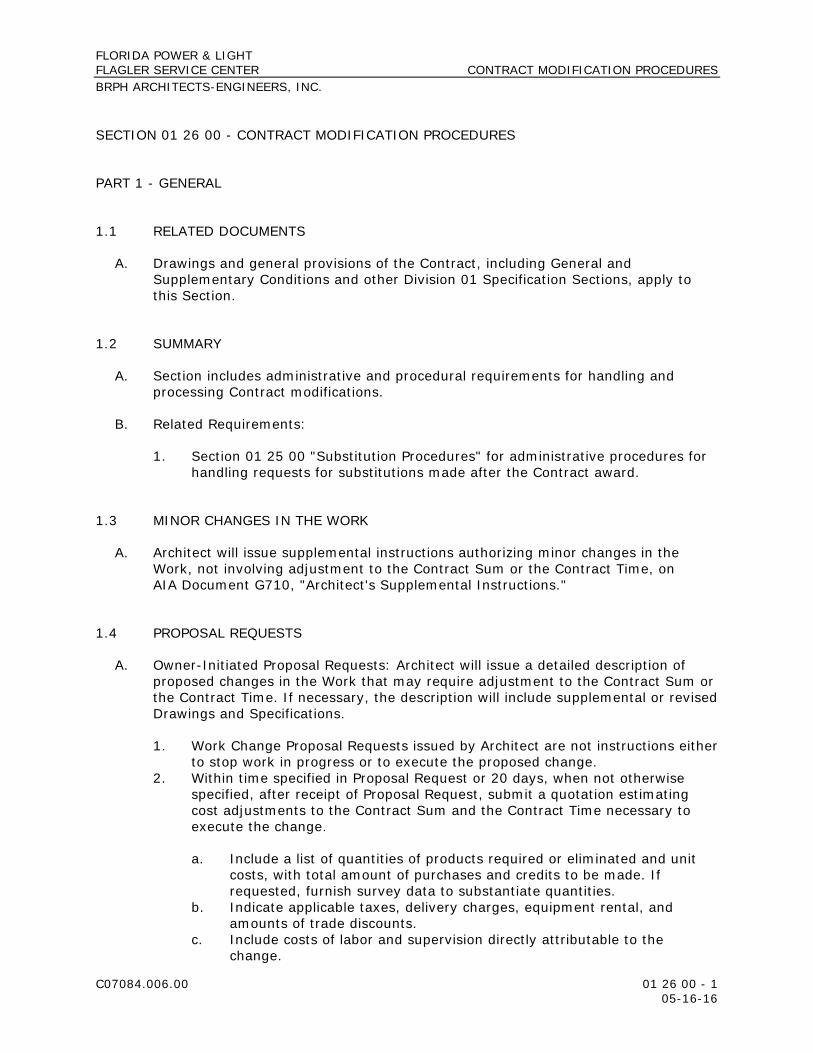
FLORIDA POWER & LIGHT FLAGLER SERVICE CENTER CONTRACT MODIFICATION PROCEDURES BRPH ARCHITECTS-ENGINEERS, INC.
C07084.006.00 01 26 00 - 1 05-16-16
SECTION 01 26 00 - CONTRACT MODIFICATION PROCEDURES
PART 1 - GENERAL
1.1 RELATED DOCUMENTS
A. Drawings and general provisions of the Contract, including General and Supplementary Conditions and other Division 01 Specification Sections, apply to this Section.
1.2 SUMMARY
A. Section includes administrative and procedural requirements for handling and processing Contract modifications.
B. Related Requirements:
1. Section 01 25 00 "Substitution Procedures" for administrative procedures for handling requests for substitutions made after the Contract award.
1.3 MINOR CHANGES IN THE WORK
A. Architect will issue supplemental instructions authorizing minor changes in the Work, not involving adjustment to the Contract Sum or the Contract Time, on AIA Document G710, "Architect's Supplemental Instructions."
1.4 PROPOSAL REQUESTS
A. Owner-Initiated Proposal Requests: Architect will issue a detailed description of proposed changes in the Work that may require adjustment to the Contract Sum or the Contract Time. If necessary, the description will include supplemental or revised Drawings and Specifications.
1. Work Change Proposal Requests issued by Architect are not instructions either to stop work in progress or to execute the proposed change.
2. Within time specified in Proposal Request or 20 days, when not otherwise specified, after receipt of Proposal Request, submit a quotation estimating cost adjustments to the Contract Sum and the Contract Time necessary to execute the change.
a. Include a list of quantities of products required or eliminated and unit costs, with total amount of purchases and credits to be made. If requested, furnish survey data to substantiate quantities.
b. Indicate applicable taxes, delivery charges, equipment rental, and amounts of trade discounts.
c. Include costs of labor and supervision directly attributable to the change.

FLORIDA POWER & LIGHT FLAGLER SERVICE CENTER CONTRACT MODIFICATION PROCEDURES BRPH ARCHITECTS-ENGINEERS, INC.
C07084.006.00 01 26 00 - 2 05-16-16
d. Include an updated Contractor's construction schedule that indicates the effect of the change, including, but not limited to, changes in activity duration, start and finish times, and activity relationship. Use available total float before requesting an extension of the Contract Time.
e. Quotation Form: Use CSI Form 13.6D, "Proposal Worksheet Summary," and Form 13.6C, "Proposal Worksheet Detail."
B. Contractor-Initiated Proposals: If latent or changed conditions require modifications to the Contract, Contractor may initiate a claim by submitting a request for a change to Owner.
1. Include a statement outlining reasons for the change and the effect of the change on the Work. Provide a complete description of the proposed change. Indicate the effect of the proposed change on the Contract Sum and the Contract Time.
2. Include a list of quantities of products required or eliminated and unit costs, with total amount of purchases and credits to be made. If requested, furnish survey data to substantiate quantities.
3. Indicate applicable taxes, delivery charges, equipment rental, and amounts of trade discounts.
4. Include costs of labor and supervision directly attributable to the change. 5. Include an updated Contractor's construction schedule that indicates the
effect of the change, including, but not limited to, changes in activity duration, start and finish times, and activity relationship. Use available total float before requesting an extension of the Contract Time.
6. Comply with requirements in Section 01 25 00 "Substitution Procedures" if the proposed change requires substitution of one product or system for product or system specified.
1.5 FIELD CORRECTION REQUESTS
A. Upon discovery of any conditions in the field that result in a deviation from the Contract Documents, a Code non-compliance issue and/or an error in construction, Contractor shall prepare and submit to Architect a Field Correction Request (FCR) Form, a copy of which is provided following this section.
B. Contractor shall provide information outlined on the FCR Form and also provide a proposed solution before submitting to Architect for review.
C. Architect shall review FCR Form and return form to Contractor within five (05) calendar days with suggested corrective measures.
D. Documentation: For reimbursement purposes, Architect shall maintain detailed records on a time and material basis of work required of Architect to address each FCR submitted.
1.6 CHANGE ORDER PROCEDURES
A. On Owner's approval of a Work Changes Proposal Request, Contractor will issue a Change Order for signatures of Owner and Contractor on AIA Document G701.

FLORIDA POWER & LIGHT FLAGLER SERVICE CENTER CONTRACT MODIFICATION PROCEDURES BRPH ARCHITECTS-ENGINEERS, INC.
C07084.006.00 01 26 00 - 3 05-16-16
1.7 CONSTRUCTION CHANGE DIRECTIVE
A. Construction Change Directive: Architect may issue a Construction Change Directive (CCD) on AIA Document G714. Construction Change Directive instructs Contractor to proceed with a change in the Work, for subsequent inclusion in a Change Order.
1. Construction Change Directive contains a complete description of change in the Work. It also designates method to be followed to determine change in the Contract Sum or the Contract Time.
B. Documentation: Maintain detailed records on a time and material basis of work required by the Construction Change Directive.
1. After completion of change, submit an itemized account and supporting data necessary to substantiate cost and time adjustments to the Contract.
PART 2 - PRODUCTS (Not Used)
PART 3 - EXECUTION (Not Used)
END OF SECTION 01 26 00

THIS PAGE INTENTIONALLY LEFT BLANK

01. Date Submitted: Number: 0000
02. Date by which Response Requested:
03. Submitting Parties:
03A. Contractor:
03B. Sucontractor:
03C. Discipline:
03D. Author:
04. Drawing Reference(s):
05. Specification Reference(s):
06. Issue:
07. Proposed Corrective Measure:
08. Support Documentation Attached:
09. Reviewer:
10. Disposition: Date:
Florida Power & Light
Flagler Service Center
FIELD CHANGE REQUEST (FCR)

THIS PAGE INTENTIONALLY LEFT BLANK

FLORIDA POWER & LIGHT FLAGLER SERVICE CENTER PAYMENT PROCEDURES BRPH ARCHITECTS-ENGINEERS, INC.
C07084.006.00 01 29 00 - 1 05-16-16
SECTION 01 29 00 - PAYMENT PROCEDURES
PART 1 - GENERAL
1.1 RELATED DOCUMENTS
A. Drawings and general provisions of the Contract, including General and Supplementary Conditions and other Division 01 Specification Sections, apply to this Section.
1.2 SUMMARY
A. Section includes administrative and procedural requirements necessary to prepare and process Applications for Payment.
B. Related Requirements:
1. Section 01 21 00 "Allowances" for procedural requirements governing the handling and processing of allowances.
2. Section 01 22 00 "Unit Prices" for administrative requirements governing the use of unit prices.
3. Section 01 26 00 "Contract Modification Procedures" for administrative procedures for handling changes to the Contract.
4. Section 01 32 00 "Construction Progress Documentation" for administrative requirements governing the preparation and submittal of the Contractor's construction schedule.
1.3 DEFINITIONS
A. Schedule of Values: A statement furnished by Contractor allocating portions of the Contract Sum to various portions of the Work and used as the basis for reviewing Contractor's Applications for Payment.
1.4 SCHEDULE OF VALUES
A. Coordination: Coordinate preparation of the schedule of values with preparation of Contractor's construction schedule.
1. Coordinate line items in the schedule of values with other required administrative forms and schedules, including the following:
a. Application for Payment forms with continuation sheets. b. Submittal schedule. c. Items required to be indicated as separate activities in Contractor's
construction schedule.

FLORIDA POWER & LIGHT FLAGLER SERVICE CENTER PAYMENT PROCEDURES BRPH ARCHITECTS-ENGINEERS, INC.
C07084.006.00 01 29 00 - 2 05-16-16
2. Submit the schedule of values to Owner at earliest possible date, but no later than seven (07) days before the date scheduled for submittal of initial Applications for Payment.
3. Subschedules for Phased Work: Where the Work is separated into phases requiring separately phased payments, provide subschedules showing values coordinated with each phase of payment.
4. Subschedules for Separate Elements of Work: Where the Contractor's construction schedule defines separate elements of the Work, provide subschedules showing values coordinated with each element.
B. Format and Content: Use Project Manual table of contents as a guide to establish line items for the schedule of values. Provide at least one line item for each Specification Section.
1. Identification: Include the following Project identification on the schedule of values:
a. Project name and location. b. Name of Architect. c. Architect's project number. d. Contractor's name and address. e. Date of submittal.
2. Arrange schedule of values consistent with format of AIA Document G703. 3. Arrange the schedule of values in tabular form with separate columns to
indicate the following for each item listed:
a. Related Specification Section or Division. b. Description of the Work. c. Name of subcontractor. d. Name of manufacturer or fabricator. e. Name of supplier. f. Change Orders (numbers) that affect value. g. Dollar value of the following, as a percentage of the Contract Sum to
nearest one-hundredth percent, adjusted to total 100 percent.
1) Labor. 2) Materials. 3) Equipment.
4. Provide a breakdown of the Contract Sum in enough detail to facilitate continued evaluation of Applications for Payment and progress reports. Coordinate with Project Manual table of contents. Provide multiple line items for principal subcontract amounts in excess of five percent (05%) of the Contract Sum.
a. Include separate line items under Contractor and principal subcontractors for Project closeout requirements in an amount totaling five percent (05%) percent of the Contract Sum and subcontract amount.
5. Round amounts to nearest whole dollar; total shall equal the Contract Sum.

FLORIDA POWER & LIGHT FLAGLER SERVICE CENTER PAYMENT PROCEDURES BRPH ARCHITECTS-ENGINEERS, INC.
C07084.006.00 01 29 00 - 3 05-16-16
6. Provide a separate line item in the schedule of values for each part of the Work where Applications for Payment may include materials or equipment purchased or fabricated and stored, but not yet installed.
a. Differentiate between items stored on-site and items stored off-site. If required, include evidence of insurance.
7. Provide separate line items in the schedule of values for initial cost of materials, for each subsequent stage of completion, and for total installed value of that part of the Work.
8. Allowances: Provide a separate line item in the schedule of values for each allowance. Show line-item value of unit-cost allowances, as a product of the unit cost, multiplied by measured quantity. Use information indicated in the Contract Documents to determine quantities.
9. Purchase Contracts: Provide a separate line item in the schedule of values for each purchase contract. Show line-item value of purchase contract. Indicate owner payments or deposits, if any, and balance to be paid by Contractor.
10. Each item in the schedule of values and Applications for Payment shall be complete. Include total cost and proportionate share of general overhead and profit for each item.
a. Temporary facilities and other major cost items that are not direct cost of actual work-in-place may be shown either as separate line items in the schedule of values or distributed as general overhead expense, at Contractor's option.
11. Schedule Updating: Update and resubmit the schedule of values before the next Applications for Payment when Change Orders or Construction Change Directives result in a change in the Contract Sum.
1.5 APPLICATIONS FOR PAYMENT
A. Each Application for Payment following the initial Application for Payment shall be consistent with previous applications and payments as certified by Architect and paid for by Owner.
1. Initial Application for Payment, Application for Payment at time of Provisional Acceptance (per the Owner’s Contract), and final Application for Payment involve additional requirements.
B. Payment Application Times: The date for each progress payment is indicated in the Agreement between Owner and Contractor. The period of construction work covered by each Application for Payment is the period indicated in the Agreement.
C. Payment Application Times: Submit Application for Payment to Architect by the first day of the month. The period covered by each Application for Payment is one month, ending on the last day of the month.
1. Submit draft copy of Application for Payment seven (07) days prior to due date for review by Architect.
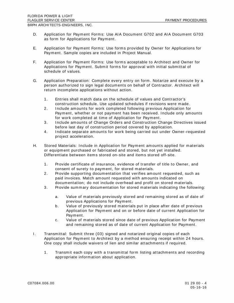
FLORIDA POWER & LIGHT FLAGLER SERVICE CENTER PAYMENT PROCEDURES BRPH ARCHITECTS-ENGINEERS, INC.
C07084.006.00 01 29 00 - 4 05-16-16
D. Application for Payment Forms: Use AIA Document G702 and AIA Document G703 as form for Applications for Payment.
E. Application for Payment Forms: Use forms provided by Owner for Applications for Payment. Sample copies are included in Project Manual.
F. Application for Payment Forms: Use forms acceptable to Architect and Owner for Applications for Payment. Submit forms for approval with initial submittal of schedule of values.
G. Application Preparation: Complete every entry on form. Notarize and execute by a person authorized to sign legal documents on behalf of Contractor. Architect will return incomplete applications without action.
1. Entries shall match data on the schedule of values and Contractor's construction schedule. Use updated schedules if revisions were made.
2. Include amounts for work completed following previous Application for Payment, whether or not payment has been received. Include only amounts for work completed at time of Application for Payment.
3. Include amounts of Change Orders and Construction Change Directives issued before last day of construction period covered by application.
4. Indicate separate amounts for work being carried out under Owner-requested project acceleration.
H. Stored Materials: Include in Application for Payment amounts applied for materials or equipment purchased or fabricated and stored, but not yet installed. Differentiate between items stored on-site and items stored off-site.
1. Provide certificate of insurance, evidence of transfer of title to Owner, and consent of surety to payment, for stored materials.
2. Provide supporting documentation that verifies amount requested, such as paid invoices. Match amount requested with amounts indicated on documentation; do not include overhead and profit on stored materials.
3. Provide summary documentation for stored materials indicating the following:
a. Value of materials previously stored and remaining stored as of date of previous Applications for Payment.
b. Value of previously stored materials put in place after date of previous Application for Payment and on or before date of current Application for Payment.
c. Value of materials stored since date of previous Application for Payment and remaining stored as of date of current Application for Payment.
I. Transmittal: Submit three (03) signed and notarized original copies of each Application for Payment to Architect by a method ensuring receipt within 24 hours. One copy shall include waivers of lien and similar attachments if required.
1. Transmit each copy with a transmittal form listing attachments and recording appropriate information about application.
FLORIDA POWER & LIGHT FLAGLER SERVICE CENTER PAYMENT PROCEDURES BRPH ARCHITECTS-ENGINEERS, INC.
C07084.006.00 01 29 00 - 5 05-16-16
J. Waivers of Mechanic's Lien: With each Application for Payment, submit waivers of mechanic's liens from subcontractors, sub-subcontractors, and suppliers for construction period covered by the previous application.
1. Submit partial waivers on each item for amount requested in previous application, after deduction for retainage, on each item.
2. When an application shows completion of an item, submit conditional final or full waivers.
3. Owner reserves the right to designate which entities involved in the Work must submit waivers.
4. Submit final Application for Payment with or preceded by conditional final waivers from every entity involved with performance of the Work covered by the application who is lawfully entitled to a lien.
5. Waiver Forms: Submit executed waivers of lien on forms, acceptable to Owner.
K. Initial Application for Payment: Administrative actions and submittals that must precede or coincide with submittal of first Application for Payment include the following:
1. List of subcontractors. 2. Schedule of values. 3. Sustainable design submittal for project materials cost data. 4. Contractor's construction schedule (preliminary if not final). 5. Combined Contractor's construction schedule (preliminary if not final)
incorporating Work of multiple contracts, with indication of acceptance of schedule by each Contractor.
6. Products list (preliminary if not final). 7. Sustainable design action plans. 8. Schedule of unit prices. 9. Submittal schedule (preliminary if not final). 10. List of Contractor's staff assignments. 11. List of Contractor's principal consultants. 12. Copies of building permits. 13. Copies of authorizations and licenses from authorities having jurisdiction for
performance of the Work. 14. Initial progress report. 15. Report of preconstruction conference. 16. Certificates of insurance and insurance policies. 17. Performance and payment bonds. 18. Data needed to acquire Owner's insurance.
L. Monthly Progress Payments: The Owner shall make partial payments for the completed work as the construction progresses, subject to retention. In accordance with the Project Specific Requirements/Supplemental Conditions, documents included therein shall be provided with each progress payment request. This will include but not limited to the Cost Management Reports and the Monthly Management Report.

FLORIDA POWER & LIGHT FLAGLER SERVICE CENTER PAYMENT PROCEDURES BRPH ARCHITECTS-ENGINEERS, INC.
C07084.006.00 01 29 00 - 6 05-16-16
M. Application for Payment at Provisional Acceptance (per the Owner’s Contract): After Architect issues the Certificate of Provisional Acceptance (per the Owner’s Contract), submit an Application for Payment showing 100 percent completion for portion of the Work claimed as substantially complete.
1. Include documentation supporting claim that the Work is substantially complete and a statement showing an accounting of changes to the Contract Sum.
2. This application shall reflect Certificate(s) of Provisional Acceptance (per the Owner’s Contract) issued previously for Owner occupancy of designated portions of the Work.
N. Final Payment Application: After completing Project closeout requirements, submit final Application for Payment with releases and supporting documentation not previously submitted and accepted, including, but not limited, to the following:
1. Evidence of completion of Project closeout requirements. 2. Insurance certificates for products and completed operations where required
and proof that taxes, fees, and similar obligations were paid. 3. Updated final statement, accounting for final changes to the Contract Sum. 4. AIA Document G706, "Contractor's Affidavit of Payment of Debts and Claims." 5. AIA Document G706A, "Contractor's Affidavit of Release of Liens." 6. AIA Document G707, "Consent of Surety to Final Payment." 7. Evidence that claims have been settled. 8. Final meter readings for utilities, a measured record of stored fuel, and similar
data as of date of Provisional Acceptance (per the Owner’s Contract) or when Owner took possession of and assumed responsibility for corresponding elements of the Work.
9. Final liquidated damages settlement statement.
PART 2 - PRODUCTS (Not Used)
PART 3 - EXECUTION (Not Used)
END OF SECTION 01 29 00
FLORIDA POWER & LIGHT FLAGLER SERVICE CENTER PROJECT MANAGEMENT AND COORDINATION BRPH ARCHITECTS-ENGINEERS, INC.
C07084.006.00 01 31 00 - 1 05-16-16
SECTION 01 31 00 - PROJECT MANAGEMENT AND COORDINATION
PART 1 - GENERAL
1.1 RELATED DOCUMENTS
A. Drawings and general provisions of the Contract, including General and Supplementary Conditions and other Division 01 Specification Sections, apply to this Section.
1.2 SUMMARY
A. Section includes administrative provisions for coordinating construction operations on Project including, but not limited to, the following:
1. General coordination procedures. 2. Coordination Drawings. 3. Requests for Information (RFIs). 4. Project Web site. 5. Project meetings. 6. Cost Management Report.
B. Each contractor shall participate in coordination requirements. Certain areas of responsibility are assigned to a specific contractor.
C. Related Requirements:
1. Section 01 12 00 "Multiple Contract Summary" for a description of the division of work among separate contracts and responsibility for coordination activities not in this Section.
2. Section 01 32 00 "Construction Progress Documentation" for preparing and submitting Contractor's construction schedule.
3. Section 01 73 00 "Execution" for procedures for coordinating general installation and field-engineering services, including establishment of benchmarks and control points.
4. Section 01 77 00 "Closeout Procedures" for coordinating closeout of the Contract.
5. Section 01 91 13 "General Commissioning Requirements" for coordinating the Work with Owner's Commissioning Authority. (This section needs to be added)
1.3 DEFINITIONS
A. RFI: Request from Owner, Architect, or Contractor seeking information required by or clarifications of the Contract Documents.

FLORIDA POWER & LIGHT FLAGLER SERVICE CENTER PROJECT MANAGEMENT AND COORDINATION BRPH ARCHITECTS-ENGINEERS, INC.
C07084.006.00 01 31 00 - 2 05-16-16
1.4 INFORMATIONAL SUBMITTALS
A. Subcontract List: Prepare a written summary identifying individuals or firms proposed for each portion of the Work, including those who are to furnish products or equipment fabricated to a special design. Use CSI Form 1.5A. Include the following information in tabular form:
1. Name, address, and telephone number of entity performing subcontract or supplying products.
2. Number and title of related Specification Section(s) covered by subcontract. 3. Drawing number and detail references, as appropriate, covered by
subcontract.
B. Key Personnel Names: Within 15 days of starting construction operations, submit a list of key personnel assignments, including superintendent and other personnel in attendance at Project site. Identify individuals and their duties and responsibilities; list addresses and telephone numbers, including home, office, and cellular telephone numbers and e-mail addresses. Provide names, addresses, and telephone numbers of individuals assigned as alternates in the absence of individuals assigned to Project.
1. Post copies of list in project meeting room, in temporary field office, on Project Web site, and by each temporary telephone. Keep list current at all times.
1.5 GENERAL COORDINATION PROCEDURES
A. Coordination: Coordinate construction operations included in different Sections of the Specifications to ensure efficient and orderly installation of each part of the Work. Coordinate construction operations, included in different Sections, that depend on each other for proper installation, connection, and operation.
1. Schedule construction operations in sequence required to obtain the best results where installation of one part of the Work depends on installation of other components, before or after its own installation.
2. Coordinate installation of different components to ensure maximum performance and accessibility for required maintenance, service, and repair.
3. Make adequate provisions to accommodate items scheduled for later installation.
B. Coordination: Each contractor shall coordinate its construction operations with those of other contractors and entities to ensure efficient and orderly installation of each part of the Work. Each contractor shall coordinate its operations with operations, included in different Sections, that depend on each other for proper installation, connection, and operation.
1. Schedule construction operations in sequence required to obtain the best results where installation of one part of the Work depends on installation of other components, before or after its own installation.
FLORIDA POWER & LIGHT FLAGLER SERVICE CENTER PROJECT MANAGEMENT AND COORDINATION BRPH ARCHITECTS-ENGINEERS, INC.
C07084.006.00 01 31 00 - 3 05-16-16
2. Coordinate installation of different components with other contractors to ensure maximum performance and accessibility for required maintenance, service, and repair.
3. Make adequate provisions to accommodate items scheduled for later installation.
C. Prepare memoranda for distribution to each party involved, outlining special procedures required for coordination. Include such items as required notices, reports, and list of attendees at meetings.
1. Prepare similar memoranda for Owner and separate contractors if coordination of their Work is required.
D. Administrative Procedures: Coordinate scheduling and timing of required administrative procedures with other construction activities and activities of other subcontractors to avoid conflicts and to ensure orderly progress of the Work. Such administrative activities include, but are not limited to, the following:
1. Preparation of Contractor's construction schedule. 2. Preparation of the schedule of values. 3. Installation and removal of temporary facilities and controls. 4. Delivery and processing of submittals. 5. Progress meetings. 6. Preinstallation conferences. 7. Project closeout activities. 8. Startup and adjustment of systems.
E. Conservation: Coordinate construction activities to ensure that operations are carried out with consideration given to conservation of energy, water, and materials. Coordinate use of temporary utilities to minimize waste.
1. Salvage materials and equipment involved in performance of, but not actually incorporated into, the Work. See other Sections for disposition of salvaged materials that are designated as Owner's property.
1.6 COORDINATION DRAWINGS
A. Coordination Drawings, General: Prepare coordination drawings according to requirements in individual Sections, and additionally where installation is not completely shown on Shop Drawings, where limited space availability necessitates coordination, or if coordination is required to facilitate integration of products and materials fabricated or installed by more than one entity.
1. Content: Project-specific information, drawn accurately to a scale large enough to indicate and resolve conflicts. Do not base coordination drawings on standard printed data. Include the following information, as applicable:
a. Use applicable Drawings as a basis for preparation of coordination drawings. Prepare sections, elevations, and details as needed to describe relationship of various systems and components.

FLORIDA POWER & LIGHT FLAGLER SERVICE CENTER PROJECT MANAGEMENT AND COORDINATION BRPH ARCHITECTS-ENGINEERS, INC.
C07084.006.00 01 31 00 - 4 05-16-16
b. Coordinate the addition of trade-specific information to the coordination drawings by multiple contractors in a sequence that best provides for coordination of the information and resolution of conflicts between installed components before submitting for review.
c. Indicate functional and spatial relationships of components of architectural, structural, civil, mechanical, and electrical systems.
d. Indicate space requirements for routine maintenance and for anticipated replacement of components during the life of the installation.
e. Show location and size of access doors required for access to concealed dampers, valves, and other controls.
f. Indicate required installation sequences. g. Indicate dimensions shown on the Drawings. Specifically note
dimensions that appear to be in conflict with submitted equipment and minimum clearance requirements. Provide alternate sketches to Architect indicating proposed resolution of such conflicts. Minor dimension changes and difficult installations will not be considered changes to the Contract.
B. Coordination Drawing Organization: Organize coordination drawings as follows:
1. Floor Plans and Reflected Ceiling Plans: Show architectural and structural elements, and mechanical, plumbing, fire-protection, fire-alarm, and electrical Work. Show locations of visible ceiling-mounted devices relative to acoustical ceiling grid. Supplement plan drawings with section drawings where required to adequately represent the Work.
2. Plenum Space: Indicate subframing for support of ceiling and wall systems, mechanical and electrical equipment, and related Work. Locate components within ceiling plenum to accommodate layout of light fixtures indicated on Drawings. Indicate areas of conflict between light fixtures and other components.
3. Mechanical Rooms: Provide coordination drawings for mechanical rooms showing plans and elevations of mechanical, plumbing, fire-protection, fire-alarm, and electrical equipment.
4. Structural Penetrations: Indicate penetrations and openings required for all disciplines.
5. Slab Edge and Embedded Items: Indicate slab edge locations and sizes and locations of embedded items for metal fabrications, sleeves, anchor bolts, bearing plates, angles, door floor closers, slab depressions for floor finishes, curbs and housekeeping pads, and similar items.
6. Mechanical and Plumbing Work: Show the following:
a. Sizes and bottom elevations of ductwork, piping, and conduit runs, including insulation, bracing, flanges, and support systems.
b. Dimensions of major components, such as dampers, valves, diffusers, access doors, cleanouts and electrical distribution equipment.
c. Fire-rated enclosures around ductwork.
7. Electrical Work: Show the following:
a. Runs of vertical and horizontal conduit 1-1/4 inches in diameter and larger.

FLORIDA POWER & LIGHT FLAGLER SERVICE CENTER PROJECT MANAGEMENT AND COORDINATION BRPH ARCHITECTS-ENGINEERS, INC.
C07084.006.00 01 31 00 - 5 05-16-16
b. Light fixture, exit light, emergency battery pack, smoke detector, and other fire-alarm locations.
c. Panel board, switch board, switchgear, transformer, busway, generator, and motor control center locations.
d. Location of pull boxes and junction boxes, dimensioned from column center lines.
8. Fire-Protection System: Show the following:
a. Locations of standpipes, mains piping, branch lines, pipe drops, and sprinkler heads.
9. Review: Architect will review coordination drawings to confirm that the Work is being coordinated, but not for the details of the coordination, which are Contractor's responsibility. If Architect determines that coordination drawings are not being prepared in sufficient scope or detail, or are otherwise deficient, Architect will so inform Contractor, who shall make changes as directed and resubmit.
10. Coordination Drawing Prints: Prepare coordination drawing prints according to requirements in Section 01 33 00 "Submittal Procedures."
C. Coordination Digital Data Files: Prepare coordination digital data files according to the following requirements:
1. File Preparation Format: Same digital data software program, version, and operating system as original Drawings.
2. File Preparation Format: DWG, Version 2015, operating in Microsoft Windows operating system.
3. File Submittal Format: Submit or post coordination drawing files using Portable Data File (PDF) format.
4. BIM File Incorporation: Develop and incorporate Contractor's and subcontractors’ coordination drawing files into Building Information Model established for Project.
a. Perform three-dimensional component conflict analysis as part of preparation of coordination drawings. Resolve component conflicts prior to submittal. Indicate where conflict resolution requires modification of design requirements by Architect.
5. Architect will furnish Contractor one set of digital data files of Drawings for use in preparing coordination digital data files.
a. Architect makes no representations as to the accuracy or completeness of digital data files as they relate to Drawings.
b. Digital Data Software Program: Drawings are available in AutoCAD 2015 and Revit 2015 for Microsoft Windows.
c. Contractor shall execute a data licensing agreement in the form of AIA Document C106.

FLORIDA POWER & LIGHT FLAGLER SERVICE CENTER PROJECT MANAGEMENT AND COORDINATION BRPH ARCHITECTS-ENGINEERS, INC.
C07084.006.00 01 31 00 - 6 05-16-16
1.7 REQUESTS FOR INFORMATION (RFIs)
A. General: Immediately on discovery of the need for additional information or interpretation of the Contract Documents, Contractor shall prepare and submit an RFI in the form specified.
1. Architect will return RFIs submitted to Architect by other entities controlled by Contractor with no response.
2. Coordinate and submit RFIs in a prompt manner so as to avoid delays in Contractor's work or work of subcontractors.
B. Content of the RFI: Include a detailed, legible description of item needing information or interpretation and the following:
1. Project name. 2. Project number. 3. Date. 4. Name of Contractor. 5. Name of Architect. 6. RFI number, numbered sequentially. 7. RFI subject. 8. Specification Section number and title and related paragraphs, as appropriate. 9. Drawing number and detail references, as appropriate. 10. Field dimensions and conditions, as appropriate. 11. Contractor's suggested resolution. If Contractor's suggested resolution
impacts the Contract Time or the Contract Sum, Contractor shall state impact in the RFI.
12. Contractor's signature. 13. Attachments: Include sketches, descriptions, measurements, photos, Product
Data, Shop Drawings, coordination drawings, and other information necessary to fully describe items needing interpretation.
a. Include dimensions, thicknesses, structural grid references, and details of affected materials, assemblies, and attachments on attached sketches.
C. RFI Forms: AIA Document G716 or software-generated form with substantially the same content as indicated above, acceptable to Architect.
1. Attachments shall be electronic files in Adobe Acrobat PDF format.
D. Architect's Action: Architect will review each RFI, determine action required, and respond. Allow seven (07) working days for Architect's response for each RFI. RFIs received by Architect after 1:00 p.m. will be considered as received the following working day.
1. The following Contractor-generated RFIs will be returned without action:
a. Requests for approval of submittals. b. Requests for approval of substitutions. c. Requests for approval of Contractor's means and methods.
FLORIDA POWER & LIGHT FLAGLER SERVICE CENTER PROJECT MANAGEMENT AND COORDINATION BRPH ARCHITECTS-ENGINEERS, INC.
C07084.006.00 01 31 00 - 7 05-16-16
d. Requests for coordination information already indicated in the Contract Documents.
e. Requests for adjustments in the Contract Time or the Contract Sum. f. Requests for interpretation of Architect's actions on submittals. g. Incomplete RFIs or inaccurately prepared RFIs.
2. Architect's action may include a request for additional information, in which case Architect's time for response will date from time of receipt of additional information.
3. Architect's action on RFIs that may result in a change to the Contract Time or the Contract Sum may be eligible for Contractor to submit Change Proposal according to Section 01 26 00 "Contract Modification Procedures."
a. If Contractor believes the RFI response warrants change in the Contract Time or the Contract Sum, notify Architect in writing within 10 working days of receipt of the RFI response.
E. RFI Log: Prepare, maintain, and submit a tabular log of RFIs organized by the RFI number. Submit log weekly. Use CSI Log Form 13.2B. Include the following:
1. Project name. 2. Name and address of Contractor. 3. Name and address of Architect. 4. RFI number including RFIs that were returned without action or withdrawn. 5. RFI description. 6. Date the RFI was submitted. 7. Date Architect's response was received.
F. On receipt of Architect's action, update the RFI log and immediately distribute the RFI response to affected parties. Review response and notify Architect seven (07) days if Contractor disagrees with response.
1. Identification of related Minor Change in the Work, Construction Change Directive, and Proposal Request, as appropriate.
2. Identification of related Field Order, Work Change Directive, and Proposal Request, as appropriate.
1.8 PROJECT WEB SITE
A. Provide, administer, and use Project Web site for purposes of hosting and managing project communication and documentation until Final Completion. Project Web site shall include the following functions:
1. Project directory. 2. Project correspondence. 3. Meeting minutes. 4. Contract modifications forms and logs. 5. RFI forms and logs. 6. Task and issue management. 7. Photo documentation. 8. Schedule and calendar management.

FLORIDA POWER & LIGHT FLAGLER SERVICE CENTER PROJECT MANAGEMENT AND COORDINATION BRPH ARCHITECTS-ENGINEERS, INC.
C07084.006.00 01 31 00 - 8 05-16-16
9. Submittals forms and logs. 10. Payment application forms. 11. Drawing and specification document hosting, viewing, and updating. 12. Online document collaboration. 13. Reminder and tracking functions. 14. Archiving functions.
B. Provide up to seven (07) Project Web site user licenses for use of the Owner, Architect, and Architect's consultants. Provide eight (08) hours of software training at Architect's office for Project Web site users.
C. On completion of Project, provide one (01) complete archive copy of Project Web site files to Owner and to Architect in a digital storage format acceptable to Architect.
D. Provide one of the following Project Web site software packages under their current published licensing agreements:
1. Autodesk, Buzzsaw. 2. Autodesk, Constructware. 3. Meridian Systems, Prolog.
E. Contractor, subcontractors, and other parties granted access by Contractor to Project Web site shall execute a data licensing agreement in the form of AIA Document C106.
1.9 PROJECT MEETINGS
A. General: Schedule and conduct meetings and conferences at Project site unless otherwise indicated.
1. Attendees: Inform participants and others involved, and individuals whose presence is required, of date and time of each meeting. Notify Owner and Architect of scheduled meeting dates and times.
2. Agenda: Prepare the meeting agenda. Distribute the agenda to all invited attendees.
3. Minutes: Entity responsible for conducting meeting will record significant discussions and agreements achieved. Distribute the meeting minutes to everyone concerned, including Owner and Architect, within three (03) working days of the meeting.
B. Preconstruction Conference: Owner will schedule and conduct a preconstruction conference before starting construction, at a time convenient to Owner and Architect, but no later than 15 working days after execution of the Agreement.
1. Conduct the conference to review responsibilities and personnel assignments. 2. Attendees: Authorized representatives of Owner, Architect, and their
consultants; Contractor and its superintendent; major subcontractors; suppliers; and other concerned parties shall attend the conference. Participants at the conference shall be familiar with Project and authorized to conclude matters relating to the Work.

FLORIDA POWER & LIGHT FLAGLER SERVICE CENTER PROJECT MANAGEMENT AND COORDINATION BRPH ARCHITECTS-ENGINEERS, INC.
C07084.006.00 01 31 00 - 9 05-16-16
3. Agenda: Discuss items of significance that could affect progress, including the following:
a. Tentative construction schedule. b. Phasing. c. Critical work sequencing and long-lead items. d. Designation of key personnel and their duties. e. Lines of communications. f. Procedures for processing field decisions and Change Orders. g. Procedures for RFIs. h. Procedures for testing and inspecting. i. Procedures for processing Applications for Payment. j. Distribution of the Contract Documents. k. Submittal procedures. l. Sustainable design requirements. m. Preparation of record documents. n. Use of the premises and existing buildings. o. Work restrictions. p. Working hours. q. Owner's occupancy requirements. r. Responsibility for temporary facilities and controls. s. Procedures for moisture and mold control. t. Procedures for disruptions and shutdowns. u. Construction waste management and recycling. v. Parking availability. w. Office, work, and storage areas. x. Equipment deliveries and priorities. y. First aid. z. Security. aa. Progress cleaning.
4. Minutes: Entity responsible for conducting meeting will record and distribute meeting minutes.
C. Project Closeout Conference: Schedule and conduct a project closeout conference, at a time convenient to Owner and Architect, but no later than 90 days prior to the scheduled date of Provisional Acceptance (per the Owner’s Contract).
1. Conduct the conference to review requirements and responsibilities related to Project closeout.
2. Attendees: Authorized representatives of Owner, Architect and their consultants; Contractor and its superintendent; major subcontractors; suppliers; and other concerned parties shall attend the meeting. Participants at the meeting shall be familiar with Project and authorized to conclude matters relating to the Work.
3. Agenda: Discuss items of significance that could affect or delay Project closeout, including the following:
a. Preparation of record documents. b. Procedures required prior to inspection for Provisional Acceptance (per
the Owner’s Contract) and for final inspection for acceptance. c. Submittal of written warranties.

FLORIDA POWER & LIGHT FLAGLER SERVICE CENTER PROJECT MANAGEMENT AND COORDINATION BRPH ARCHITECTS-ENGINEERS, INC.
C07084.006.00 01 31 00 - 10 05-16-16
d. Requirements for completing sustainable design documentation. e. Requirements for preparing operations and maintenance data. f. Requirements for delivery of material samples, attic stock, and spare
parts. g. Requirements for demonstration and training. h. Preparation of Contractor's punch list. i. Procedures for processing Applications for Payment at Provisional
Acceptance (per the Owner’s Contract) and for final payment. j. Submittal procedures. k. Coordination of separate contracts. l. Owner's partial occupancy requirements. m. Installation of Owner's furniture, fixtures, and equipment. n. Responsibility for removing temporary facilities and controls.
4. Minutes: Entity conducting meeting will record and distribute meeting minutes.
D. Progress Meetings: Conduct progress meetings at biweekly intervals.
1. Coordinate dates of meetings with preparation of payment requests. 2. Attendees: In addition to representatives of Owner and Architect, each
contractor, subcontractor, supplier, and other entity concerned with current progress or involved in planning, coordination, or performance of future activities shall be represented at these meetings. All participants at the meeting shall be familiar with Project and authorized to conclude matters relating to the Work.
3. Agenda: Review and correct or approve minutes of previous progress meeting. Review other items of significance that could affect progress. Include topics for discussion as appropriate to status of Project.
a. Contractor's Construction Schedule: Review progress since the last meeting. Determine whether each activity is on time, ahead of schedule, or behind schedule, in relation to Contractor's construction schedule. Determine how construction behind schedule will be expedited; secure commitments from parties involved to do so. Discuss whether schedule revisions are required to ensure that current and subsequent activities will be completed within the Contract Time.
1) Review schedule for next period.
b. Review present and future needs of each entity present, including the following:
1) Interface requirements. 2) Sequence of operations. 3) Resolution of BIM component conflicts. 4) Status of submittals. 5) Status of sustainable design documentation. 6) Deliveries. 7) Off-site fabrication. 8) Access. 9) Site utilization.

FLORIDA POWER & LIGHT FLAGLER SERVICE CENTER PROJECT MANAGEMENT AND COORDINATION BRPH ARCHITECTS-ENGINEERS, INC.
C07084.006.00 01 31 00 - 11 05-16-16
10) Temporary facilities and controls. 11) Progress cleaning. 12) Quality and work standards. 13) Status of correction of deficient items. 14) Field observations. 15) Status of RFIs. 16) Status of proposal requests. 17) Pending changes. 18) Status of Change Orders. 19) Pending claims and disputes. 20) Documentation of information for payment requests.
4. Minutes: Entity responsible for conducting the meeting will record and distribute the meeting minutes to each party present and to parties requiring information.
a. Schedule Updating: Revise Contractor's construction schedule after each progress meeting where revisions to the schedule have been made or recognized. Issue revised schedule concurrently with the report of each meeting.
E. Coordination Meetings: Conduct Project Coordination meetings at biweekly intervals. Project coordination meetings are in addition to specific meetings held for other purposes, such as progress meetings and preinstallation conferences.
1. Attendees: In addition to representatives of Owner and Architect, each contractor, subcontractor, supplier, and other entity concerned with current progress or involved in planning, coordination, or performance of future activities shall be represented at these meetings. All participants at the meetings shall be familiar with Project and authorized to conclude matters relating to the Work.
2. Agenda: Review and correct or approve minutes of the previous coordination meeting. Review other items of significance that could affect progress. Include topics for discussion as appropriate to status of Project.
a. Combined Contractor's Construction Schedule: Review progress since the last coordination meeting. Determine whether each contract is on time, ahead of schedule, or behind schedule, in relation to combined Contractor's construction schedule. Determine how construction behind schedule will be expedited; secure commitments from parties involved to do so. Discuss whether schedule revisions are required to ensure that current and subsequent activities will be completed within the Contract Time.
b. Schedule Updating: Revise combined Contractor's construction schedule after each coordination meeting where revisions to the schedule have been made or recognized. Issue revised schedule concurrently with report of each meeting.

FLORIDA POWER & LIGHT FLAGLER SERVICE CENTER PROJECT MANAGEMENT AND COORDINATION BRPH ARCHITECTS-ENGINEERS, INC.
C07084.006.00 01 31 00 - 12 05-16-16
c. Review present and future needs of each contractor present, including the following:
1) Interface requirements. 2) Sequence of operations. 3) Resolution of BIM component conflicts. 4) Status of submittals. 5) Deliveries. 6) Off-site fabrication. 7) Access. 8) Site utilization. 9) Temporary facilities and controls. 10) Work hours. 11) Hazards and risks. 12) Progress cleaning. 13) Quality and work standards. 14) Change Orders.
3. Reporting: Record meeting results and distribute copies to everyone in attendance and to others affected by decisions or actions resulting from each meeting.
4. Cost Management Report: Supplier shall provide a “Cost Management Report” on a bi-weekly basis which includes at a minimum the Claims, Changes or extra work, delays or accelerations, interferences or impacts known to Supplier that have occurred or may be claimed to have occurred since project onset. This information is required to be provided in Microsoft Excel. This Cost Management Report will be cumulative and include current status of aforementioned items, initiated dates, dollar exposure amounts (incremental to the executed contract amount), drawing references, subcontractor documentation, etc. as required to establish an understanding of the issues. If there are no known Claims, Changes, etc. the Cost Management Report shall still be issued bi-weekly stating NONE. The most recent Cost Management Report shall be attached to each Supplier invoice.
PART 2 - PRODUCTS (Not Used)
PART 3 - EXECUTION (Not Used)
END OF SECTION 01 31 00

FLORIDA POWER & LIGHT FLAGLER SERVICE CENTER CONSTRUCTION PROGRESS DOCUMENTATION BRPH ARCHITECTS-ENGINEERS, INC.
C07084.006.00 01 32 00 - 1 05-16-16
SECTION 01 32 00 - CONSTRUCTION PROGRESS DOCUMENTATION
PART 1 - GENERAL
1.1 RELATED DOCUMENTS
A. Drawings and general provisions of the Contract, including General and Supplementary Conditions and other Division 01 Specification Sections, apply to this Section.
1.2 SUMMARY
A. Section includes administrative and procedural requirements for documenting the progress of construction during performance of the Work, including the following:
1. Startup construction schedule. 2. Contractor's construction schedule. 3. Construction schedule updating reports. 4. Daily construction reports. 5. Material location reports. 6. Site condition reports. 7. Special reports.
B. Related Requirements:
1. Section 01 12 00 "Multiple Contract Summary" for preparing a combined Contractor's construction schedule.
2. Section 01 33 00 "Submittal Procedures" for submitting schedules and reports.
3. Section 01 40 00 "Quality Requirements" for submitting a schedule of tests and inspections.
1.3 DEFINITIONS
A. Activity: A discrete part of a project that can be identified for planning, scheduling, monitoring, and controlling the construction project. Activities included in a construction schedule consume time and resources.
1. Critical Activity: An activity on the critical path that must start and finish on the planned early start and finish times.
2. Predecessor Activity: An activity that precedes another activity in the network.
3. Successor Activity: An activity that follows another activity in the network.
B. Cost Loading: The allocation of the schedule of values for the completion of an activity as scheduled. The sum of costs for all activities must equal the total Contract Sum unless otherwise approved by Owner.
FLORIDA POWER & LIGHT FLAGLER SERVICE CENTER CONSTRUCTION PROGRESS DOCUMENTATION BRPH ARCHITECTS-ENGINEERS, INC.
C07084.006.00 01 32 00 - 2 05-16-16
C. CPM: Critical path method, which is a method of planning and scheduling a construction project where activities are arranged based on activity relationships. Network calculations determine when activities can be performed and the critical path of Project.
D. Critical Path: The longest connected chain of interdependent activities through the network schedule that establishes the minimum overall Project duration and contains no float.
E. Event: The starting or ending point of an activity.
F. Float: The measure of leeway in starting and completing an activity.
1. Float time is not for the exclusive use or benefit of either Owner or Contractor, but is a jointly owned, expiring Project resource available to both parties as needed to meet schedule milestones and Contract completion date.
2. Free float is the amount of time an activity can be delayed without adversely affecting the early start of the successor activity.
3. Total float is the measure of leeway in starting or completing an activity without adversely affecting the planned Project completion date.
1.4 INFORMATIONAL SUBMITTALS
A. Format for Submittals: Submit required submittals in the following format:
1. Working electronic copy of schedule file, where indicated. 2. PDF electronic file.
B. Startup construction schedule.
1. Approval of cost-loaded, startup construction schedule will not constitute approval of schedule of values for cost-loaded activities.
C. Startup Network Diagram: Of size required to display entire network for entire construction period. Show logic ties for activities.
D. Contractor's Construction Schedule: Initial schedule, of size required to display entire schedule for entire construction period.
1. Submit a working electronic copy of schedule, using software indicated, and labeled to comply with requirements for submittals. Include type of schedule (initial or updated) and date on label.
E. CPM Reports: Concurrent with CPM schedule, submit each of the following reports. Format for each activity in reports shall contain activity number, activity description, cost and resource loading, original duration, remaining duration, early start date, early finish date, late start date, late finish date, and total float in calendar days.
1. Activity Report: List of all activities sorted by activity number and then early start date, or actual start date if known.
FLORIDA POWER & LIGHT FLAGLER SERVICE CENTER CONSTRUCTION PROGRESS DOCUMENTATION BRPH ARCHITECTS-ENGINEERS, INC.
C07084.006.00 01 32 00 - 3 05-16-16
2. Logic Report: List of preceding and succeeding activities for all activities, sorted in ascending order by activity number and then early start date, or actual start date if known.
3. Total Float Report: List of all activities sorted in ascending order of total float. 4. Earnings Report: Compilation of Contractor's total earnings from the Notice to
Proceed until most recent Application for Payment.
F. Construction Schedule Updating Reports: Submit with Applications for Payment.
G. Daily Construction Reports: Submit at weekly intervals.
H. Material Location Reports: Submit at weekly intervals.
I. Site Condition Reports: Submit at time of discovery of differing conditions.
J. Special Reports: Submit at time of unusual event.
K. Qualification Data: For scheduling consultant.
1.5 QUALITY ASSURANCE
A. Scheduling Consultant Qualifications: An experienced specialist in CPM scheduling and reporting, with capability of producing CPM reports and diagrams within 24 hours of Architect's request.
B. Prescheduling Conference: Conduct conference at Project site to comply with requirements in Section 01 31 00 "Project Management and Coordination." Review methods and procedures related to the preliminary construction schedule and Contractor's construction schedule, including, but not limited to, the following:
1. Review software limitations and content and format for reports. 2. Verify availability of qualified personnel needed to develop and update
schedule. 3. Discuss constraints, including phasing, work stages, area separations, interim
milestones and partial Owner occupancy. 4. Review delivery dates for Owner-furnished products. 5. Review schedule for work of Owner's separate contracts. 6. Review submittal requirements and procedures. 7. Review time required for review of submittals and resubmittals. 8. Review requirements for tests and inspections by independent testing and
inspecting agencies. 9. Review time required for Project closeout and Owner startup procedures,
including commissioning activities. 10. Review and finalize list of construction activities to be included in schedule. 11. Review procedures for updating schedule.

FLORIDA POWER & LIGHT FLAGLER SERVICE CENTER CONSTRUCTION PROGRESS DOCUMENTATION BRPH ARCHITECTS-ENGINEERS, INC.
C07084.006.00 01 32 00 - 4 05-16-16
1.6 COORDINATION
A. Coordinate Contractor's construction schedule with the schedule of values, list of subcontractors, submittal schedule, progress reports, payment requests, and other required schedules and reports.
1. Secure time commitments for performing critical elements of the Work from entities involved.
2. Coordinate each construction activity in the network with other activities and schedule them in proper sequence.
PART 2 - PRODUCTS
2.1 CONTRACTOR'S CONSTRUCTION SCHEDULE, GENERAL
A. Time Frame: Extend schedule from date established for the Notice of Award to date of final completion.
1. Contract completion date shall not be changed by submission of a schedule that shows an early completion date, unless specifically authorized by Change Order.
B. Activities: Treat each story or separate area as a separate numbered activity for each main element of the Work. Comply with the following:
1. Activity Duration: Define activities so no activity is longer than 20 calendar days, unless specifically allowed by Architect.
2. Procurement Activities: Include procurement process activities for the following long lead items and major items, requiring a cycle of more than 60 days, as separate activities in schedule. Procurement cycle activities include, but are not limited to, submittals, approvals, purchasing, fabrication, and delivery. a. HVAC equipment. b. Stand-by Generator. c. Water Heaters.
3. Submittal Review Time: Include review and resubmittal times indicated in Section 01 33 00 "Submittal Procedures" in schedule. Coordinate submittal review times in Contractor's construction schedule with submittal schedule.
4. Startup and Testing Time: Include no fewer than 15 calendar days for startup and testing.
5. Provisional Acceptance (per the Owner’s Contract): Indicate completion in advance of date established for Provisional Acceptance (per the Owner’s Contract), and allow time for Architect's administrative procedures necessary for certification of Provisional Acceptance (per the Owner’s Contract).
6. Punch List and Final Completion: Include not more than 30 calendar days for completion of punch list items and final completion.
FLORIDA POWER & LIGHT FLAGLER SERVICE CENTER CONSTRUCTION PROGRESS DOCUMENTATION BRPH ARCHITECTS-ENGINEERS, INC.
C07084.006.00 01 32 00 - 5 05-16-16
C. Constraints: Include constraints and work restrictions indicated in the Contract Documents and as follows in schedule, and show how the sequence of the Work is affected.
1. Phasing: Arrange list of activities on schedule by phase. 2. Work under More Than One Contract: Include a separate activity for each
contract. 3. Work by Owner: Include a separate activity for each portion of the Work
performed by Owner. 4. Products Ordered in Advance: Include a separate activity for each product.
Include delivery date indicated in Section 01 10 00 "Summary." Delivery dates indicated stipulate the earliest possible delivery date.
5. Owner-Furnished Products: Include a separate activity for each product. Include delivery date indicated in Section 01 10 00 "Summary." Delivery dates indicated stipulate the earliest possible delivery date.
6. Work Restrictions: Show the effect of the following items on the schedule:
a. Coordination with existing construction. b. Limitations of continued occupancies. c. Uninterruptible services. d. Partial occupancy before Provisional Acceptance (per the Owner’s
Contract). e. Use of premises restrictions. f. Provisions for future construction. g. Seasonal variations. h. Environmental control.
7. Work Stages: Indicate important stages of construction for each major portion of the Work, including, but not limited to, the following:
a. Subcontract awards. b. Submittals. c. Purchases. d. Mockups. e. Fabrication. f. Sample testing. g. Deliveries. h. Installation. i. Tests and inspections. j. Adjusting. k. Curing. l. Building flush-out. m. Startup and placement into final use and operation.
8. Construction Areas: Identify each major area of construction for each major portion of the Work. Indicate where each construction activity within a major area must be sequenced or integrated with other construction activities to provide for the following:
a. Structural completion. b. Temporary enclosure and space conditioning. c. Permanent space enclosure.

FLORIDA POWER & LIGHT FLAGLER SERVICE CENTER CONSTRUCTION PROGRESS DOCUMENTATION BRPH ARCHITECTS-ENGINEERS, INC.
C07084.006.00 01 32 00 - 6 05-16-16
d. Completion of mechanical installation. e. Completion of electrical installation. f. Provisional Acceptance (per the Owner’s Contract).
D. Milestones: Include milestones indicated in the Contract Documents in schedule, including, but not limited to, the Notice to Proceed, Provisional Acceptance (per the Owner’s Contract), and final completion, and the following interim milestones:
1. Casting of concrete tilt-wall panels. 2. Erection of concrete tilt-wall panels. 3. Temporary enclosure and space conditioning.
E. Cost Correlation: Superimpose a cost correlation timeline, indicating planned and actual costs. On the line, show planned and actual dollar volume of the Work performed as of planned and actual dates used for preparation of payment requests.
1. See Section 01 29 00 "Payment Procedures" for cost reporting and payment procedures.
F. Upcoming Work Summary: Prepare summary report indicating activities scheduled to occur or commence prior to submittal of next schedule update. Summarize the following issues:
1. Unresolved issues. 2. Unanswered Requests for Information. 3. Rejected or unreturned submittals. 4. Notations on returned submittals. 5. Pending modifications affecting the Work and Contract Time.
G. Recovery Schedule: When periodic update indicates the Work is 14 or more calendar days behind the current approved schedule, submit a separate recovery schedule indicating means by which Contractor intends to regain compliance with the schedule. Indicate changes to working hours, working days, crew sizes, and equipment required to achieve compliance, and date by which recovery will be accomplished.
H. Computer Scheduling Software: Prepare schedules using current version of a program that has been developed specifically to manage construction schedules.
1. Use Microsoft Project.
2.2 STARTUP CONSTRUCTION SCHEDULE
A. Bar-Chart Schedule: Submit startup, horizontal, bar-chart-type construction schedule within seven (07) days of date established for the Notice of Award.
B. Preparation: Indicate each significant construction activity separately. Identify first workday of each week with a continuous vertical line. Outline significant construction activities for first 90 days of construction. Include skeleton diagram for the remainder of the Work and a cash requirement prediction based on indicated activities.

FLORIDA POWER & LIGHT FLAGLER SERVICE CENTER CONSTRUCTION PROGRESS DOCUMENTATION BRPH ARCHITECTS-ENGINEERS, INC.
C07084.006.00 01 32 00 - 7 05-16-16
2.3 CONTRACTOR'S CONSTRUCTION SCHEDULE (GANTT CHART)
A. Gantt-Chart Schedule: Submit a comprehensive, fully developed, horizontal, Gantt-chart-type, Contractor's construction schedule within 30 calendar days of date established for the Notice of Award. Base schedule on the startup construction schedule and additional information received since the start of Project.
B. Preparation: Indicate each significant construction activity separately. Identify first workday of each week with a continuous vertical line.
1. For construction activities that require three months or longer to complete, indicate an estimated completion percentage in 10 percent increments within time bar.
2.4 CONTRACTOR'S CONSTRUCTION SCHEDULE (CPM SCHEDULE)
A. General: Prepare network diagrams using AON (activity-on-node) format.
B. Startup Network Diagram: Submit diagram within 14 calendar days of date established for the Notice of Award. Outline significant construction activities for the first 90 calendar days of construction. Include skeleton diagram for the remainder of the Work and a cash requirement prediction based on indicated activities.
C. CPM Schedule: Prepare Contractor's construction schedule using a time-scaled CPM network analysis diagram for the Work.
1. Develop network diagram in sufficient time to submit CPM schedule so it can be accepted for use no later than 60 calendar days after date established for the Notice of Award.
a. Failure to include any work item required for performance of this Contract shall not excuse Contractor from completing all work within applicable completion dates, regardless of Architect's approval of the schedule.
2. Conduct educational workshops to train and inform key Project personnel, including subcontractors' personnel, in proper methods of providing data and using CPM schedule information.
3. Establish procedures for monitoring and updating CPM schedule and for reporting progress. Coordinate procedures with progress meeting and payment request dates.
4. Use "one workday" as the unit of time for individual activities. Indicate nonworking days and holidays incorporated into the schedule in order to coordinate with the Contract Time.
D. CPM Schedule Preparation: Prepare a list of all activities required to complete the Work. Using the startup network diagram, prepare a skeleton network to identify probable critical paths.

FLORIDA POWER & LIGHT FLAGLER SERVICE CENTER CONSTRUCTION PROGRESS DOCUMENTATION BRPH ARCHITECTS-ENGINEERS, INC.
C07084.006.00 01 32 00 - 8 05-16-16
1. Activities: Indicate the estimated time duration, sequence requirements, and relationship of each activity in relation to other activities. Include estimated time frames for the following activities:
a. Preparation and processing of submittals. b. Mobilization and demobilization. c. Purchase of materials. d. Delivery. e. Fabrication. f. Utility interruptions. g. Installation. h. Work by Owner that may affect or be affected by Contractor's activities. i. Testing and commissioning. j. Punch list and final completion. k. Activities occurring following final completion.
2. Critical Path Activities: Identify critical path activities, including those for interim completion dates. Scheduled start and completion dates shall be consistent with Contract milestone dates.
3. Processing: Process data to produce output data on a computer-drawn, time-scaled network. Revise data, reorganize activity sequences, and reproduce as often as necessary to produce the CPM schedule within the limitations of the Contract Time.
4. Format: Mark the critical path. Locate the critical path near center of network; locate paths with most float near the edges.
a. Subnetworks on separate sheets are permissible for activities clearly off the critical path.
5. Cost- and Resource-Loading of CPM Schedule: Assign cost to construction activities on the CPM schedule. Do not assign costs to submittal activities. Obtain Architect's approval prior to assigning costs to fabrication and delivery activities. Assign costs under main subcontracts for testing and commissioning activities, operation and maintenance manuals, punch list activities, Project record documents, and demonstration and training (if applicable), in the amount of five percent (05%) of the Contract Sum.
a. Each activity cost shall reflect an appropriate value subject to approval by Architect.
b. Total cost assigned to activities shall equal the total Contract Sum.
E. Contract Modifications: For each proposed contract modification and concurrent with its submission, prepare a time-impact analysis using a network fragment to demonstrate the effect of the proposed change on the overall project schedule.
F. Initial Issue of Schedule: Prepare initial network diagram from a sorted activity list indicating straight "early start-total float." Identify critical activities. Prepare tabulated reports showing the following:
1. Contractor or subcontractor and the Work or activity. 2. Description of activity. 3. Main events of activity.

FLORIDA POWER & LIGHT FLAGLER SERVICE CENTER CONSTRUCTION PROGRESS DOCUMENTATION BRPH ARCHITECTS-ENGINEERS, INC.
C07084.006.00 01 32 00 - 9 05-16-16
4. Immediate preceding and succeeding activities. 5. Early and late start dates. 6. Early and late finish dates. 7. Activity duration in workdays. 8. Total float or slack time. 9. Average size of workforce. 10. Dollar value of activity (coordinated with the schedule of values).
G. Schedule Updating: Concurrent with making revisions to schedule, prepare tabulated reports showing the following:
1. Identification of activities that have changed. 2. Changes in early and late start dates. 3. Changes in early and late finish dates. 4. Changes in activity durations in workdays. 5. Changes in the critical path. 6. Changes in total float or slack time. 7. Changes in the Contract Time.
H. Value Summaries: Prepare two cumulative value lists, sorted by finish dates.
1. In first list, tabulate activity number, early finish date, dollar value, and cumulative dollar value.
2. In second list, tabulate activity number, late finish date, dollar value, and cumulative dollar value.
3. In subsequent issues of both lists, substitute actual finish dates for activities completed as of list date.
4. Prepare list for ease of comparison with payment requests; coordinate timing with progress meetings.
a. In both value summary lists, tabulate "actual percent complete" and "cumulative value completed" with total at bottom.
b. Submit value summary printouts one (01) week before each regularly scheduled progress meeting.
2.5 REPORTS
A. Daily Construction Reports: Prepare a daily construction report recording the following information concerning events at Project site:
1. List of subcontractors at Project site. 2. List of separate contractors at Project site. 3. Approximate count of personnel at Project site. 4. Equipment at Project site. 5. Material deliveries. 6. High and low temperatures and general weather conditions, including
presence of rain or snow. 7. Accidents. 8. Meetings and significant decisions. 9. Unusual events (see special reports). 10. Stoppages, delays, shortages, and losses.

FLORIDA POWER & LIGHT FLAGLER SERVICE CENTER CONSTRUCTION PROGRESS DOCUMENTATION BRPH ARCHITECTS-ENGINEERS, INC.
C07084.006.00 01 32 00 - 10 05-16-16
11. Meter readings and similar recordings. 12. Emergency procedures. 13. Orders and requests of authorities having jurisdiction. 14. Change Orders received and implemented. 15. Construction Change Directives (CCDs) received and implemented. 16. Services connected and disconnected. 17. Equipment or system tests and startups. 18. Partial completions and occupancies. 19. Provisional Acceptance (per the Owner’s Contract) authorized.
B. Material Location Reports: At monthly intervals, prepare and submit a comprehensive list of materials delivered to and stored at Project site. List shall be cumulative, showing materials previously reported plus items recently delivered. Include with list a statement of progress on and delivery dates for materials or items of equipment fabricated or stored away from Project site. Indicate the following categories for stored materials:
1. Material stored prior to previous report and remaining in storage. 2. Material stored prior to previous report and since removed from storage and
installed. 3. Material stored following previous report and remaining in storage.
C. Site Condition Reports: Immediately on discovery of a difference between site conditions and the Contract Documents, prepare and submit a detailed report. Submit with a Request for Information. Include a detailed description of the differing conditions, together with recommendations for changing the Contract Documents.
2.6 SPECIAL REPORTS
A. General: Submit special reports directly to Owner within one (01) day of an occurrence. Distribute copies of report to parties affected by the occurrence.
B. Reporting Unusual Events: When an event of an unusual and significant nature occurs at Project site, whether or not related directly to the Work, prepare and submit a special report. List chain of events, persons participating, response by Contractor's personnel, evaluation of results or effects, and similar pertinent information. Advise Owner in advance when these events are known or predictable.
PART 3 - EXECUTION
3.1 CONTRACTOR'S CONSTRUCTION SCHEDULE
A. Scheduling Consultant: Engage a consultant to provide planning, evaluation, and reporting using CPM scheduling.
1. In-House Option: Owner may waive the requirement to retain a consultant if Contractor employs skilled personnel with experience in CPM scheduling and reporting techniques. Submit qualifications.
FLORIDA POWER & LIGHT FLAGLER SERVICE CENTER CONSTRUCTION PROGRESS DOCUMENTATION BRPH ARCHITECTS-ENGINEERS, INC.
C07084.006.00 01 32 00 - 11 05-16-16
2. Meetings: Scheduling consultant shall attend all meetings related to Project progress, alleged delays, and time impact.
B. Contractor's Construction Schedule Updating: At monthly intervals, update schedule to reflect actual construction progress and activities. Issue schedule one (01) week before each regularly scheduled progress meeting.
1. Revise schedule immediately after each meeting or other activity where revisions have been recognized or made. Issue updated schedule concurrently with the report of each such meeting.
2. Include a report with updated schedule that indicates every change, including, but not limited to, changes in logic, durations, actual starts and finishes, and activity durations.
3. As the Work progresses, indicate final completion percentage for each activity.
C. Distribution: Distribute copies of approved schedule to Architect, Owner, separate subcontractors, testing and inspecting agencies, and other parties identified by Contractor with a need-to-know schedule responsibility.
1. Post copies in Project meeting rooms and temporary field offices. 2. When revisions are made, distribute updated schedules to the same parties
and post in the same locations. Delete parties from distribution when they have completed their assigned portion of the Work and are no longer involved in performance of construction activities.
END OF SECTION 01 32 00

THIS PAGE INTENTIONALLY LEFT BLANK
FLORIDA POWER & LIGHT FLAGLER SERVICE CENTER PHOTOGRAPHIC DOCUMENTATION BRPH ARCHITECTS-ENGINEERS, INC.
C07084.006.00 01 32 33 - 1 05-16-16
SECTION 01 32 33 - PHOTOGRAPHIC DOCUMENTATION
PART 1 - GENERAL
1.1 RELATED DOCUMENTS
A. Drawings and general provisions of the Contract, including General and Supplementary Conditions and other Division 01 Specification Sections, apply to this Section.
1.2 SUMMARY
A. Section includes administrative and procedural requirements for the following:
1. Preconstruction photographs. 2. Periodic construction photographs. 3. Final completion construction photographs. 4. Preconstruction video recordings. 5. Periodic construction video recordings. 6. Web-based construction photographic documentation.
B. Related Requirements:
1. Section 01 22 00 "Unit Prices" for procedures for unit prices for extra photographs.
2. Section 01 33 00 "Submittal Procedures" for submitting photographic documentation.
3. Section 01 77 00 "Closeout Procedures" for submitting photographic documentation as project record documents at Project closeout.
4. Section 01 79 00 "Demonstration and Training" for submitting video recordings of demonstration of equipment and training of Owner's personnel.
5. Section 02 41 16 "Structure Demolition" for photographic documentation before building demolition operations commence.
6. Section 02 41 19 "Selective Structure Demolition" for photographic documentation before selective demolition operations commence.
7. Section 31 10 00 "Site Clearing" for photographic documentation before site clearing operations commence.
1.3 ALLOWANCES
A. Costs: Photographic documentation services are included under the cash allowance for construction photographic services established in Section 01 21 00 "Allowances."

FLORIDA POWER & LIGHT FLAGLER SERVICE CENTER PHOTOGRAPHIC DOCUMENTATION BRPH ARCHITECTS-ENGINEERS, INC.
C07084.006.00 01 32 33 - 2 05-16-16
1.4 UNIT PRICES
A. Basis for Bids: Base number of construction photographs on average of 20 photographs per week over the duration of Project.
1.5 INFORMATIONAL SUBMITTALS
A. Qualification Data: For photographer(s).
B. Key Plan: Submit key plan of Project site and building with notation of vantage points marked for location and direction of each photograph and/or video recording. Indicate elevation or story of construction. Include same information as corresponding photographic documentation.
C. Digital Photographs: Submit image files within three (03) days of taking photographs.
1. Digital Camera: Minimum sensor resolution of 16 megapixels. 2. Format: Minimum 3200 by 2400 pixels, in unaltered original files, with same
aspect ratio as the sensor, uncropped, date and time stamped, in folder named by date of photograph, accompanied by key plan file.
3. Identification: Provide the following information with each image description in file metadata tag:
a. Name of Project. b. Name and contact information for photographer. c. Name of Architect. d. Name of Contractor. e. Date photograph was taken. f. Description of vantage point, indicating location, direction (by compass
point), and elevation or story of construction. g. Unique sequential identifier keyed to accompanying key plan.
1.6 QUALITY ASSURANCE
A. Photographer Qualifications: An individual who has been regularly engaged as a professional photographer of construction projects for not less than three years.
1.7 USAGE RIGHTS
A. Obtain and transfer copyright usage rights from photographer to Owner for unlimited reproduction of photographic documentation.

FLORIDA POWER & LIGHT FLAGLER SERVICE CENTER PHOTOGRAPHIC DOCUMENTATION BRPH ARCHITECTS-ENGINEERS, INC.
C07084.006.00 01 32 33 - 3 05-16-16
PART 2 - PRODUCTS
2.1 PHOTOGRAPHIC MEDIA
A. Digital Images: Provide images in JPG format, produced by a digital camera with minimum sensor size of 16 megapixels, and at an image resolution of not less than 3200 by 2400 pixels.
B. Digital Video Recordings: Provide high-resolution, digital video in format acceptable to Architect.
PART 3 - EXECUTION
3.1 CONSTRUCTION PHOTOGRAPHS
A. Photographer: Engage a qualified photographer to take construction photographs.
B. General: Take photographs using the maximum range of depth of field, and that are in focus, to clearly show the Work. Photographs with blurry or out-of-focus areas will not be accepted.
1. Maintain key plan with each set of construction photographs that identifies each photographic location.
C. Digital Images: Submit digital images exactly as originally recorded in the digital camera, without alteration, manipulation, editing, or modifications using image-editing software.
1. Date and Time: Include date and time in file name for each image. 2. Field Office Images: Maintain one set of images accessible in the field office at
Project site, available at all times for reference. Identify images in the same manner as those submitted to Architect.
D. Preconstruction Photographs: Before commencement of excavation, commencement of demolition and/or commencing construction, take photographs of Project site and surrounding properties, including existing items to remain during construction, from different vantage points, as directed by Architect.
1. Flag excavation areas and construction limits before taking construction photographs.
2. Take 20 photographs to show existing conditions adjacent to property before starting the Work.
3. Take 20 photographs of existing buildings either on or adjoining property to accurately record physical conditions at start of construction.
4. Take additional photographs as required to record settlement or cracking of adjacent structures, pavements, and improvements.

FLORIDA POWER & LIGHT FLAGLER SERVICE CENTER PHOTOGRAPHIC DOCUMENTATION BRPH ARCHITECTS-ENGINEERS, INC.
C07084.006.00 01 32 33 - 4 05-16-16
E. Periodic Construction Photographs: Take 20 photographs weekly, with timing each month adjusted to coincide with the cutoff date associated with each Application for Payment. Select vantage points to show status of construction and progress since last photographs were taken.
F. Time-Lapse Sequence Construction Photographs: Take 20 photographs as indicated, to show status of construction and progress since last photographs were taken.
1. Frequency: Take photographs weekly, with timing each month adjusted to coincide with the cutoff date associated with each Application for Payment.
2. Vantage Points: Following suggestions by Architect and Contractor, photographer to select vantage points. During each of the following construction phases, take not less than two (02) of the required shots from same vantage point each time to create a time-lapse sequence as follows:
a. Commencement of the Work, through completion of subgrade construction.
b. Above-grade structural framing. c. Exterior building enclosure. d. Interior Work, through date of Provisional Acceptance (per the Owner’s
Contract).
G. Final Completion Construction Photographs: Take 20 color photographs after date of Provisional Acceptance (per the Owner’s Contract) for submission as project record documents. Architect will inform photographer of desired vantage points.
1. Do not include date stamp.
H. Additional Photographs: Architect may request photographs in addition to periodic photographs specified. Additional photographs will be paid for by Change Order and are not included in the Contract Sum or in the allowance for construction photographs.
1. Three days' notice will be given, where feasible. 2. In emergency situations, take additional photographs within 24 hours of
request. 3. Circumstances that could require additional photographs include, but are not
limited to, the following:
a. Special events planned at Project site. b. Immediate follow-up when on-site events result in construction damage
or losses. c. Photographs to be taken at fabrication locations away from Project site.
These photographs are not subject to unit prices or unit-cost allowances.
d. Provisional Acceptance (per the Owner’s Contract) of a major phase or component of the Work.
e. Extra record photographs at time of final acceptance. f. Owner's request for special publicity photographs.
END OF SECTION 01 32 33
FLORIDA POWER & LIGHT FLAGLER SERVICE CENTER SUBMITTAL PROCEDURES BRPH ARCHITECTS-ENGINEERS, INC.
C07084.006.00 01 33 00 - 1 05-16-16
SECTION 01 33 00 - SUBMITTAL PROCEDURES
PART 1 - GENERAL
1.1 RELATED DOCUMENTS
A. Drawings and general provisions of the Contract, including General and Supplementary Conditions and other Division 01 Specification Sections, apply to this Section.
1.2 SUMMARY
A. Section includes requirements for the submittal schedule and administrative and procedural requirements for submitting Shop Drawings, Product Data, Samples, and other submittals.
B. Related Requirements:
1. Section 01 29 00 "Payment Procedures" for submitting Applications for Payment and the schedule of values.
2. Section 01 32 00 "Construction Progress Documentation" for submitting schedules and reports, including Contractor's construction schedule.
3. Section 01 78 23 "Operation and Maintenance Data" for submitting operation and maintenance manuals.
4. Section 01 78 39 "Project Record Documents" for submitting record Drawings, record Specifications, and record Product Data.
5. Section 01 79 00 "Demonstration and Training" for submitting video recordings of demonstration of equipment and training of Owner's personnel.
1.3 DEFINITIONS
A. Action Submittals: Written and graphic information and physical samples that require Architect's and Owner’s Representative responsive action. Action submittals are those submittals indicated in individual Specification Sections as "action submittals."
B. Informational Submittals: Written and graphic information and physical samples that do not require Architect's and Owner’s Representative responsive action. Submittals may be rejected for not complying with requirements. Informational submittals are those submittals indicated in individual Specification Sections as "informational submittals."
C. File Transfer Protocol (FTP): Communications protocol that enables transfer of files to and from another computer over a network and that serves as the basis for standard Internet protocols. An FTP site is a portion of a network located outside of network firewalls within which internal and external users are able to access files.
FLORIDA POWER & LIGHT FLAGLER SERVICE CENTER SUBMITTAL PROCEDURES BRPH ARCHITECTS-ENGINEERS, INC.
C07084.006.00 01 33 00 - 2 05-16-16
D. Portable Document Format (PDF): An open standard file format licensed by Adobe Systems used for representing documents in a device-independent and display resolution-independent fixed-layout document format.
1.4 ACTION SUBMITTALS
A. Submittal Schedule: Submit a schedule of submittals, arranged in chronological order by dates required by construction schedule. Include time required for review, ordering, manufacturing, fabrication, and delivery when establishing dates. Include additional time required for making corrections or revisions to submittals noted by Architect and Owner’s Representative and additional time for handling and reviewing submittals required by those corrections.
1. Coordinate submittal schedule with list of subcontracts, the schedule of values, and Contractor's construction schedule.
2. Initial Submittal: Submit concurrently with startup construction schedule. Include submittals required during the first 60 days of construction. List those submittals required to maintain orderly progress of the Work and those required early because of long lead time for manufacture or fabrication.
3. Final Submittal: Submit concurrently with the first complete submittal of Contractor's construction schedule.
a. Submit revised submittal schedule to reflect changes in current status and timing for submittals.
4. Format: Arrange the following information in a tabular format:
a. Scheduled date for first submittal. b. Specification Section number and title. c. Submittal category: Action; informational. d. Name of subcontractor. e. Description of the Work covered. f. Scheduled date for Architect's and Owner’s Representative final release
or approval. g. Scheduled date of fabrication. h. Scheduled dates for purchasing. i. Scheduled dates for installation. j. Activity or event number.
1.5 SUBMITTAL ADMINISTRATIVE REQUIREMENTS
A. Coordination: Coordinate preparation and processing of submittals with performance of construction activities.
1. Coordinate each submittal with fabrication, purchasing, testing, delivery, other submittals, and related activities that require sequential activity.
2. Submit all submittal items required for each Specification Section concurrently unless partial submittals for portions of the Work are indicated on approved submittal schedule.

FLORIDA POWER & LIGHT FLAGLER SERVICE CENTER SUBMITTAL PROCEDURES BRPH ARCHITECTS-ENGINEERS, INC.
C07084.006.00 01 33 00 - 3 05-16-16
3. Submit action submittals and informational submittals required by the same Specification Section as separate packages under separate transmittals.
4. Coordinate transmittal of different types of submittals for related parts of the Work so processing will not be delayed because of need to review submittals concurrently for coordination.
a. Owner’s Representative reserves the right to withhold action on a submittal requiring coordination with other submittals until related submittals are received.
B. Processing Time: Allow time for submittal review, including time for resubmittals, as follows. Time for review shall commence on Owner’s Representative’s receipt of submittal. No extension of the Contract Time will be authorized because of failure to transmit submittals enough in advance of the Work to permit processing, including resubmittals.
1. Initial Review: Allow 15 days for initial review of each submittal. Allow additional time if coordination with subsequent submittals is required. Owner’s Representative will advise Contractor when a submittal being processed must be delayed for coordination.
2. Intermediate Review: If intermediate submittal is necessary, process it in same manner as initial submittal.
3. Resubmittal Review: Allow 15 days for review of each resubmittal. 4. Sequential Review: Where sequential review of submittals by Architect's
consultants, Owner, or other parties is indicated, allow 15 days for initial review of each submittal.
C. Paper Submittals: Place a permanent label or title block on each submittal item for identification.
1. Indicate name of firm or entity that prepared each submittal on label or title block.
2. Provide a space approximately 6 by 8 inches on label or beside title block to record Contractor's review and approval markings and action taken by Architect and Owner’s Representative.
3. Include the following information for processing and recording action taken:
a. Project name. b. Date. c. Name of Architect. d. Name of Owner’s Representative. e. Name of Contractor. f. Name of subcontractor. g. Name of supplier. h. Name of manufacturer. i. Submittal number or other unique identifier, including revision identifier.
1) Submittal number shall use Specification Section number followed by a decimal point and then a sequential number (e.g., 061000.01). Resubmittals shall include an alphabetic suffix after another decimal point (e.g., 061000.01.A).
FLORIDA POWER & LIGHT FLAGLER SERVICE CENTER SUBMITTAL PROCEDURES BRPH ARCHITECTS-ENGINEERS, INC.
C07084.006.00 01 33 00 - 4 05-16-16
j. Number and title of appropriate Specification Section. k. Drawing number and detail references, as appropriate. l. Location(s) where product is to be installed, as appropriate. m. Other necessary identification.
4. Additional Paper Copies: Unless additional copies are required for final submittal, and unless Architect or Owner’s Representative observes noncompliance with provisions in the Contract Documents, initial submittal may serve as final submittal.
a. Submit one copy of submittal to concurrent reviewer in addition to specified number of copies to Architect and Owner’s Representative.
5. Transmittal for Paper Submittals: Assemble each submittal individually and appropriately for transmittal and handling. Transmit each submittal using a transmittal form. Architect and Owner’s Representative will discard submittals received from sources other than Contractor.
a. Transmittal Form for Paper Submittals: Use facsimile of sample form included in Project Manual.
b. Transmittal Form for Paper Submittals: Provide locations on form for the following information:
1) Project name. 2) Date. 3) Destination (To:). 4) Source (From:). 5) Name and address of Architect. 6) Name of Owner’s Representative. 7) Name of Contractor. 8) Name of firm or entity that prepared submittal. 9) Names of subcontractor, manufacturer, and supplier. 10) Category and type of submittal. 11) Submittal purpose and description. 12) Specification Section number and title. 13) Specification paragraph number or drawing designation and
generic name for each of multiple items. 14) Drawing number and detail references, as appropriate. 15) Indication of full or partial submittal. 16) Transmittal number, numbered consecutively. 17) Submittal and transmittal distribution record. 18) Remarks. 19) Signature of transmitter.
D. Electronic Submittals: Identify and incorporate information in each electronic submittal file as follows:
1. Assemble complete submittal package into a single indexed file incorporating submittal requirements of a single Specification Section and transmittal form with links enabling navigation to each item.
2. Name file with submittal number or other unique identifier, including revision identifier.

FLORIDA POWER & LIGHT FLAGLER SERVICE CENTER SUBMITTAL PROCEDURES BRPH ARCHITECTS-ENGINEERS, INC.
C07084.006.00 01 33 00 - 5 05-16-16
a. File name shall use project identifier and Specification Section number followed by a decimal point and then a sequential number (e.g., LNHS-061000.01). Resubmittals shall include an alphabetic suffix after another decimal point (e.g., LNHS-061000.01.A).
3. Provide means for insertion to permanently record Contractor's review and approval markings and action taken by Architect and Owner’s Representative.
4. Transmittal Form for Electronic Submittals: Use electronic form acceptable to Owner, containing the following information:
a. Project name. b. Date. c. Name and address of Architect. d. Name of Owner’s Representative. e. Name of Contractor. f. Name of firm or entity that prepared submittal. g. Names of subcontractor, manufacturer, and supplier. h. Category and type of submittal. i. Submittal purpose and description. j. Specification Section number and title. k. Specification paragraph number or drawing designation and generic
name for each of multiple items. l. Drawing number and detail references, as appropriate. m. Location(s) where product is to be installed, as appropriate. n. Related physical samples submitted directly. o. Indication of full or partial submittal. p. Transmittal number, numbered consecutively. q. Submittal and transmittal distribution record. r. Other necessary identification. s. Remarks.
5. Metadata: Include the following information as keywords in the electronic submittal file metadata:
a. Project name. b. Number and title of appropriate Specification Section. c. Manufacturer name. d. Product name.
E. Options: Identify options requiring selection by Architect.
F. Deviations and Additional Information: On an attached separate sheet, prepared on Contractor's letterhead, record relevant information, requests for data, revisions other than those requested by Architect and Owner’s Representative on previous submittals, and deviations from requirements in the Contract Documents, including minor variations and limitations. Include same identification information as related submittal.
G. Resubmittals: Make resubmittals in same form and number of copies as initial submittal.
1. Note date and content of previous submittal.

FLORIDA POWER & LIGHT FLAGLER SERVICE CENTER SUBMITTAL PROCEDURES BRPH ARCHITECTS-ENGINEERS, INC.
C07084.006.00 01 33 00 - 6 05-16-16
2. Note date and content of revision in label or title block and clearly indicate extent of revision.
3. Resubmit submittals until they are marked with approval notation from Architect's and Owner's Representative action stamp.
H. Distribution: Furnish copies of final submittals to manufacturers, subcontractors, suppliers, fabricators, installers, authorities having jurisdiction, and others as necessary for performance of construction activities. Show distribution on transmittal forms.
I. Use for Construction: Retain complete copies of submittals on Project site. Use only final action submittals that are marked with approval notation from Architect's and Owner’s Representative's action stamp.
PART 2 - PRODUCTS
2.1 SUBMITTAL PROCEDURES
A. General Submittal Procedure Requirements: Prepare and submit submittals required by individual Specification Sections. Types of submittals are indicated in individual Specification Sections.
1. Post electronic submittals as PDF electronic files directly to Project Web site specifically established for Project.
a. Architect, through Owner’s Representative, will return annotated file. Annotate and retain one copy of file as an electronic Project record document file.
2. Submit electronic submittals via email as PDF electronic files.
a. Architect, through Owner’s Representative, will return annotated file. Annotate and retain one copy of file as an electronic Project record document file.
3. Action Submittals: Submit three paper copies of each submittal unless otherwise indicated. Architect, through Owner’s Representative, will return two copies.
4. Informational Submittals: Submit two paper copies of each submittal unless otherwise indicated. Architect and Owner’s Representative will not return copies.
5. Certificates and Certifications Submittals: Provide a statement that includes signature of entity responsible for preparing certification. Certificates and certifications shall be signed by an officer or other individual authorized to sign documents on behalf of that entity.
a. Provide a digital signature with digital certificate on electronically submitted certificates and certifications where indicated.
b. Provide a notarized statement on original paper copy certificates and certifications where indicated.

FLORIDA POWER & LIGHT FLAGLER SERVICE CENTER SUBMITTAL PROCEDURES BRPH ARCHITECTS-ENGINEERS, INC.
C07084.006.00 01 33 00 - 7 05-16-16
B. Product Data: Collect information into a single submittal for each element of construction and type of product or equipment.
1. If information must be specially prepared for submittal because standard published data are not suitable for use, submit as Shop Drawings, not as Product Data.
2. Mark each copy of each submittal to show which products and options are applicable.
3. Include the following information, as applicable:
a. Manufacturer's catalog cuts. b. Manufacturer's product specifications. c. Standard color charts. d. Statement of compliance with specified referenced standards. e. Testing by recognized testing agency. f. Application of testing agency labels and seals. g. Notation of coordination requirements. h. Availability and delivery time information.
4. For equipment, include the following in addition to the above, as applicable:
a. Wiring diagrams showing factory-installed wiring. b. Printed performance curves. c. Operational range diagrams. d. Clearances required to other construction, if not indicated on
accompanying Shop Drawings.
5. Submit Product Data before or concurrent with Samples. 6. Submit Product Data in the following format:
a. PDF electronic file. b. Three paper copies of Product Data unless otherwise indicated.
Architect, through Owner’s Representative, will return two copies.
C. Shop Drawings: Prepare Project-specific information, drawn accurately to scale. Do not base Shop Drawings on reproductions of the Contract Documents or standard printed data.
1. Preparation: Fully illustrate requirements in the Contract Documents. Include the following information, as applicable:
a. Identification of products. b. Schedules. c. Compliance with specified standards. d. Notation of coordination requirements. e. Notation of dimensions established by field measurement. f. Relationship and attachment to adjoining construction clearly indicated. g. Seal and signature of professional engineer if specified.
2. Sheet Size: Except for templates, patterns, and similar full-size drawings, submit Shop Drawings on sheets at least 8-1/2 by 11 inches, but no larger than 30 by 42 inches.

FLORIDA POWER & LIGHT FLAGLER SERVICE CENTER SUBMITTAL PROCEDURES BRPH ARCHITECTS-ENGINEERS, INC.
C07084.006.00 01 33 00 - 8 05-16-16
3. Submit Shop Drawings in the following format:
a. PDF electronic file. b. Two opaque (bond) copies of each submittal. Architect, through Owner’s
Representative, will return one copy. c. Three opaque copies of each submittal. Architect and Owner’s
Representative will retain two copies; remainder will be returned.
D. Samples: Submit Samples for review of kind, color, pattern, and texture for a check of these characteristics with other elements and for a comparison of these characteristics between submittal and actual component as delivered and installed.
1. Transmit Samples that contain multiple, related components such as accessories together in one submittal package.
2. Identification: Attach label on unexposed side of Samples that includes the following:
a. Generic description of Sample. b. Product name and name of manufacturer. c. Sample source. d. Number and title of applicable Specification Section. e. Specification paragraph number and generic name of each item.
3. For projects where electronic submittals are required, provide corresponding electronic submittal of Sample transmittal, digital image file illustrating Sample characteristics, and identification information for record.
4. Disposition: Maintain sets of approved Samples at Project site, available for quality-control comparisons throughout the course of construction activity. Sample sets may be used to determine final acceptance of construction associated with each set.
a. Samples that may be incorporated into the Work are indicated in individual Specification Sections. Such Samples must be in an undamaged condition at time of use.
b. Samples not incorporated into the Work, or otherwise designated as Owner's property, are the property of Contractor.
5. Samples for Initial Selection: Submit manufacturer's color charts consisting of units or sections of units showing the full range of colors, textures, and patterns available.
a. Number of Samples: Submit two full sets of available choices where color, pattern, texture, or similar characteristics are required to be selected from manufacturer's product line. Architect, through Owner’s Representative, will return submittal with options selected.

FLORIDA POWER & LIGHT FLAGLER SERVICE CENTER SUBMITTAL PROCEDURES BRPH ARCHITECTS-ENGINEERS, INC.
C07084.006.00 01 33 00 - 9 05-16-16
6. Samples for Verification: Submit full-size units or Samples of size indicated, prepared from same material to be used for the Work, cured and finished in manner specified, and physically identical with material or product proposed for use, and that show full range of color and texture variations expected. Samples include, but are not limited to, the following: partial sections of manufactured or fabricated components; small cuts or containers of materials; complete units of repetitively used materials; swatches showing color, texture, and pattern; color range sets; and components used for independent testing and inspection.
a. Number of Samples: Submit three sets of Samples. Architect and Owner’s Representative will retain two Sample sets; remainder will be returned. Mark up and retain one returned Sample set as a project record sample.
1) Submit a single Sample where assembly details, workmanship, fabrication techniques, connections, operation, and other similar characteristics are to be demonstrated.
2) If variation in color, pattern, texture, or other characteristic is inherent in material or product represented by a Sample, submit at least three sets of paired units that show approximate limits of variations.
E. Product Schedule: As required in individual Specification Sections, prepare a written summary indicating types of products required for the Work and their intended location. Include the following information in tabular form:
1. Type of product. Include unique identifier for each product indicated in the Contract Documents or assigned by Contractor if none is indicated.
2. Manufacturer and product name, and model number if applicable. 3. Number and name of room or space. 4. Location within room or space. 5. Submit product schedule in the following format:
a. PDF electronic file. b. Three paper copies of product schedule or list unless otherwise
indicated. Architect, through Owner’s Representative, will return two copies.
F. Coordination Drawing Submittals: Comply with requirements specified in Section 01 31 00 "Project Management and Coordination."
G. Contractor's Construction Schedule: Comply with requirements specified in Section 01 32 00 "Construction Progress Documentation."
H. Application for Payment and Schedule of Values: Comply with requirements specified in Section 01 29 00 "Payment Procedures."
I. Test and Inspection Reports and Schedule of Tests and Inspections Submittals: Comply with requirements specified in Section 01 40 00 "Quality Requirements."

FLORIDA POWER & LIGHT FLAGLER SERVICE CENTER SUBMITTAL PROCEDURES BRPH ARCHITECTS-ENGINEERS, INC.
C07084.006.00 01 33 00 - 10 05-16-16
J. Closeout Submittals and Maintenance Material Submittals: Comply with requirements specified in Section 01 77 00 "Closeout Procedures."
K. Maintenance Data: Comply with requirements specified in Section 01 78 23 "Operation and Maintenance Data."
L. Qualification Data: Prepare written information that demonstrates capabilities and experience of firm or person. Include lists of completed projects with project names and addresses, contact information of architects and owners, and other information specified.
M. Welding Certificates: Prepare written certification that welding procedures and personnel comply with requirements in the Contract Documents. Submit record of Welding Procedure Specification and Procedure Qualification Record on AWS forms. Include names of firms and personnel certified.
N. Installer Certificates: Submit written statements on manufacturer's letterhead certifying that Installer complies with requirements in the Contract Documents and, where required, is authorized by manufacturer for this specific Project.
O. Manufacturer Certificates: Submit written statements on manufacturer's letterhead certifying that manufacturer complies with requirements in the Contract Documents. Include evidence of manufacturing experience where required.
P. Product Certificates: Submit written statements on manufacturer's letterhead certifying that product complies with requirements in the Contract Documents.
Q. Material Certificates: Submit written statements on manufacturer's letterhead certifying that material complies with requirements in the Contract Documents.
R. Material Test Reports: Submit reports written by a qualified testing agency, on testing agency's standard form, indicating and interpreting test results of material for compliance with requirements in the Contract Documents.
S. Product Test Reports: Submit written reports indicating that current product produced by manufacturer complies with requirements in the Contract Documents. Base reports on evaluation of tests performed by manufacturer and witnessed by a qualified testing agency, or on comprehensive tests performed by a qualified testing agency.
T. Research Reports: Submit written evidence, from a model code organization acceptable to authorities having jurisdiction, that product complies with building code in effect for Project. Include the following information:
1. Name of evaluation organization. 2. Date of evaluation. 3. Time period when report is in effect. 4. Product and manufacturers' names. 5. Description of product. 6. Test procedures and results. 7. Limitations of use.
FLORIDA POWER & LIGHT FLAGLER SERVICE CENTER SUBMITTAL PROCEDURES BRPH ARCHITECTS-ENGINEERS, INC.
C07084.006.00 01 33 00 - 11 05-16-16
U. Preconstruction Test Reports: Submit reports written by a qualified testing agency, on testing agency's standard form, indicating and interpreting results of tests performed before installation of product, for compliance with performance requirements in the Contract Documents.
V. Compatibility Test Reports: Submit reports written by a qualified testing agency, on testing agency's standard form, indicating and interpreting results of compatibility tests performed before installation of product. Include written recommendations for primers and substrate preparation needed for adhesion.
W. Field Test Reports: Submit written reports indicating and interpreting results of field tests performed either during installation of product or after product is installed in its final location, for compliance with requirements in the Contract Documents.
X. Design Data: Prepare and submit written and graphic information, including, but not limited to, performance and design criteria, list of applicable codes and regulations, and calculations. Include list of assumptions and other performance and design criteria and a summary of loads. Include load diagrams if applicable. Provide name and version of software, if any, used for calculations. Include page numbers.
2.2 DELEGATED-DESIGN SERVICES
A. Performance and Design Criteria: Where professional design services or certifications by a design professional are specifically required of Contractor by the Contract Documents, provide products and systems complying with specific performance and design criteria indicated.
1. If criteria indicated are not sufficient to perform services or certification required, submit a written request for additional information to Architect.
B. Delegated-Design Services Certification: In addition to Shop Drawings, Product Data, and other required submittals, submit digitally signed PDF electronic file and three paper copies of certificate, signed and sealed by the responsible design professional, for each product and system specifically assigned to Contractor to be designed or certified by a design professional.
1. Indicate that products and systems comply with performance and design criteria in the Contract Documents. Include list of codes, loads, and other factors used in performing these services.
PART 3 - EXECUTION
3.1 CONTRACTOR'S REVIEW
A. Action and Informational Submittals: Review each submittal and check for coordination with other Work of the Contract and for compliance with the Contract Documents. Note corrections and field dimensions. Mark with approval stamp before submitting to Architect and Owner’s Representative.
FLORIDA POWER & LIGHT FLAGLER SERVICE CENTER SUBMITTAL PROCEDURES BRPH ARCHITECTS-ENGINEERS, INC.
C07084.006.00 01 33 00 - 12 05-16-16
B. Project Closeout and Maintenance Material Submittals: See requirements in Section 01 77 00 "Closeout Procedures."
C. Approval Stamp: Stamp each submittal with a uniform, approval stamp. Include Project name and location, submittal number, Specification Section title and number, name of reviewer, date of Contractor's approval, and statement certifying that submittal has been reviewed, checked, and approved for compliance with the Contract Documents.
3.2 ARCHITECT'S AND OWNER'S REPRESENTATIVE’S ACTION
A. Action Submittals: Architect will review each submittal, make marks to indicate corrections or revisions required, and return it. Architect and Owner’s Representative will stamp each submittal with an action stamp and will mark stamp appropriately to indicate action.
B. Informational Submittals: Architect and Owner’s Representative will review each submittal and will not return it, or will return it if it does not comply with requirements. Architect and Owner’s Representative will forward each submittal to appropriate party.
C. Partial submittals prepared for a portion of the Work will be reviewed when use of partial submittals has received prior approval from Architect and Owner’s Representative.
D. Incomplete submittals are unacceptable, will be considered nonresponsive, and will be returned for resubmittal without review.
E. Submittals not required by the Contract Documents may be returned by the Architect without action.
END OF SECTION 01 33 00

Section Number Section Name Product
Data Samples Shop Dwgs Schedules
Delegated Design Calcs Coord
DwgsWiring
DiagramsCertifications Qualifications Test Reports Warranties Attic stock O&M
Manual
As-Built/ Record Dwgs
Product Data
01 05 50 Project Permits
01 10 00 Summary
01 12 00 Multiple Contract Summary
01 21 00 Allowances
01 22 00 Unit Prices
01 23 00 Alternates
01 25 00 Substitution Procedures
01 26 00 Contract Modification Procedures
01 29 00 Payment Procedures
01 31 00 Project Management and Coordination
01 32 00 Construction Progress Documentation
01 32 33 Photographic Documentation
01 33 00 Submittal Procedures
01 40 00 Quality Requirements
01 50 00 Temporary Facilities and Controls
01 56 39 Temporary Tree and Plant Protection
01 60 00 Product Requirements
01 73 00 Execution
SUBMITTAL REQUIREMENTSACTION INFORMATION
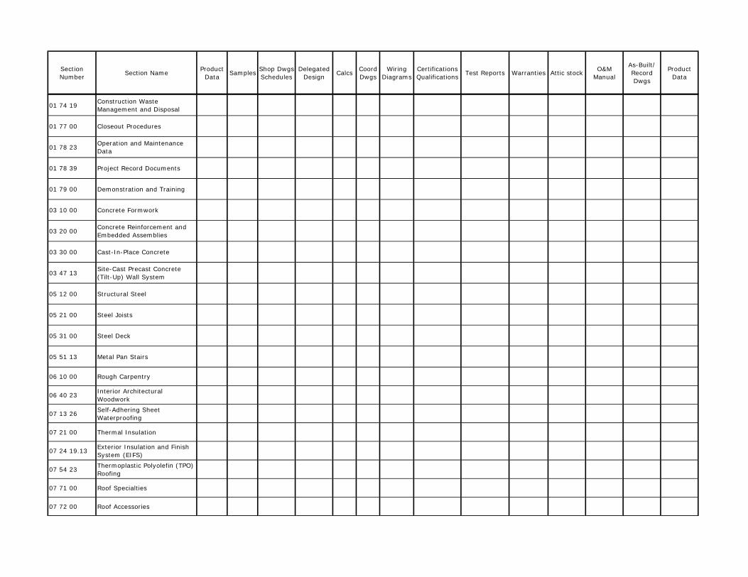
Section Number Section Name Product
Data Samples Shop Dwgs Schedules
Delegated Design Calcs Coord
DwgsWiring
DiagramsCertifications Qualifications Test Reports Warranties Attic stock O&M
Manual
As-Built/ Record Dwgs
Product Data
01 74 19 Construction Waste Management and Disposal
01 77 00 Closeout Procedures
01 78 23 Operation and Maintenance Data
01 78 39 Project Record Documents
01 79 00 Demonstration and Training
03 10 00 Concrete Formwork
03 20 00 Concrete Reinforcement and Embedded Assemblies
03 30 00 Cast-In-Place Concrete
03 47 13 Site-Cast Precast Concrete (Tilt-Up) Wall System
05 12 00 Structural Steel
05 21 00 Steel Joists
05 31 00 Steel Deck
05 51 13 Metal Pan Stairs
06 10 00 Rough Carpentry
06 40 23 Interior Architectural Woodwork
07 13 26 Self-Adhering Sheet Waterproofing
07 21 00 Thermal Insulation
07 24 19.13 Exterior Insulation and Finish System (EIFS)
07 54 23 Thermoplastic Polyolefin (TPO) Roofing
07 71 00 Roof Specialties
07 72 00 Roof Accessories

Section Number Section Name Product
Data Samples Shop Dwgs Schedules
Delegated Design Calcs Coord
DwgsWiring
DiagramsCertifications Qualifications Test Reports Warranties Attic stock O&M
Manual
As-Built/ Record Dwgs
Product Data
07 84 13 Penetration Firestopping
07 84 43 Joint Firestopping
07 92 00 Joint Sealants
08 11 13 Hollow Metal Doors and Frames
08 14 16 Flush Wood Doors
08 31 13 Access Doors and Frames
08 33 23 Overhead Coiling Doors
08 41 13 Aluminum-Framed Entrances and Storefronts
08 71 00 Door Hardware
08 80 00 Glazing
08 91 19 Fixed Louvers
09 22 16 Non-Structural Metal Framing
09 29 00 Gypsum Board
09 30 00 Wall and Floor Tiling
09 30 00.13 Metal Edge Transition Strip for Floors and Walls
09 51 13 Acoustical Panel Ceilings
09 65 13 Resilient Base and Accessories
09 65 19 Resilient Floor Tile
09 65 36 Static-Control Resilient Flooring
09 68 13 Tile Carpeting
09 91 23 Interior Painting and Exterior Painting
10 14 23 Panel Signage
10 21 13 Toilet Compartments
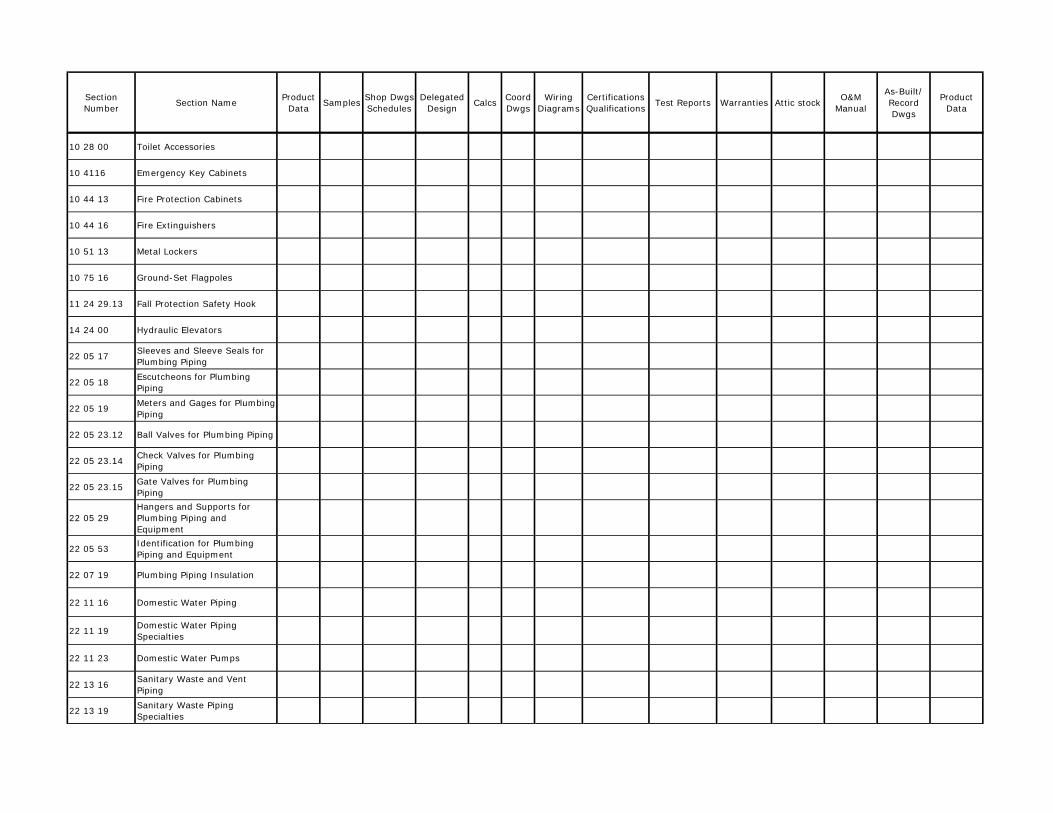
Section Number Section Name Product
Data Samples Shop Dwgs Schedules
Delegated Design Calcs Coord
DwgsWiring
DiagramsCertifications Qualifications Test Reports Warranties Attic stock O&M
Manual
As-Built/ Record Dwgs
Product Data
10 28 00 Toilet Accessories
10 4116 Emergency Key Cabinets
10 44 13 Fire Protection Cabinets
10 44 16 Fire Extinguishers
10 51 13 Metal Lockers
10 75 16 Ground-Set Flagpoles
11 24 29.13 Fall Protection Safety Hook
14 24 00 Hydraulic Elevators
22 05 17 Sleeves and Sleeve Seals for Plumbing Piping
22 05 18 Escutcheons for Plumbing Piping
22 05 19 Meters and Gages for Plumbing Piping
22 05 23.12 Ball Valves for Plumbing Piping
22 05 23.14 Check Valves for Plumbing Piping
22 05 23.15 Gate Valves for Plumbing Piping
22 05 29Hangers and Supports for Plumbing Piping and Equipment
22 05 53 Identification for Plumbing Piping and Equipment
22 07 19 Plumbing Piping Insulation
22 11 16 Domestic Water Piping
22 11 19 Domestic Water Piping Specialties
22 11 23 Domestic Water Pumps
22 13 16 Sanitary Waste and Vent Piping
22 13 19 Sanitary Waste Piping Specialties

Section Number Section Name Product
Data Samples Shop Dwgs Schedules
Delegated Design Calcs Coord
DwgsWiring
DiagramsCertifications Qualifications Test Reports Warranties Attic stock O&M
Manual
As-Built/ Record Dwgs
Product Data
22 13 19.13 Sanitary Drains
22 33 00 Electric, Domestic-Water Heaters
22 42 13.13 Commercial Water Closets
22 42 13.16 Commercial Urinals
22 42 16.13 Commercial Lavatories
22 42 16.16 Commercial Sinks
22 42 23 Commercial Showers
23 05 00 Basic Mechanical Requirements
23 05 13 Common Motor Requirements for HVAC Equipment
23 05 17 Sleeves and Sleeve Seals for HVAC Piping
23 05 19 Meters and Gages for HVAC Piping
23 05 29 Hangers and Supports for HVAC Piping and Equipment
23 05 48Vibration and Seismic Controls for HVAC Piping and Equipment
23 05 53 Identification for HVAC Piping and Equipment
23 05 93 Testing, Adjusting, and Balancing for HVAC
23 07 13 Duct Insulation
23 09 00 Instrumentation and Control for HVAC
23 31 13 Metal Ducts
23 33 00 Air Duct Accessories
23 34 23 HVAC Power Ventilators
23 72 13 Air Handling Units with Coils
23 72 13.13 Air Cooled Condensing Units
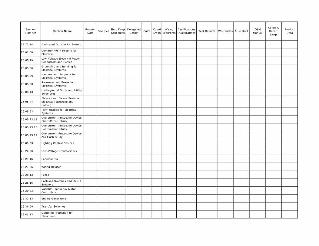
Section Number Section Name Product
Data Samples Shop Dwgs Schedules
Delegated Design Calcs Coord
DwgsWiring
DiagramsCertifications Qualifications Test Reports Warranties Attic stock O&M
Manual
As-Built/ Record Dwgs
Product Data
23 72 14 Dedicated Outside Air System
26 01 00 Common Work Results for Electrical
26 05 19 Low-Voltage Electrical Power Conductors and Cables
26 05 26 Grounding and Bonding for Electrical Systems
26 05 29 Hangers and Supports for Electrical Systems
26 05 33 Raceways and Boxes for Electrical Systems
26 05 43 Underground Ducts and Utility Structures
26 05 44Sleeves and Sleeve Seals for Electrical Raceways and Cabling
26 05 53 Identification for Electrical Systems
26 05 73.13 Overcurrent Protective Device Short-Circuit Study
26 05 73.16 Overcurrent Protective Device Coordination Study
26 05 73.19 Overcurrent Protective Device Arc-Flash Study
26 09 23 Lighting Control Devices
26 22 00 Low-Voltage Transformers
26 24 16 Panelboards
26 27 26 Wiring Devices
26 28 13 Fuses
26 28 16 Enclosed Switches and Circuit Breakers
26 29 23 Variable-Frequency Motor Controllers
26 32 13 Engine Generators
26 36 00 Transfer Switches
26 41 13 Lightning Protection for Structures

Section Number Section Name Product
Data Samples Shop Dwgs Schedules
Delegated Design Calcs Coord
DwgsWiring
DiagramsCertifications Qualifications Test Reports Warranties Attic stock O&M
Manual
As-Built/ Record Dwgs
Product Data
26 43 13Surge Protection for Low-Voltage Electrical Power Circuits
26 51 19 LED Interior Lighting
26 52 19 Exit Lighting
26 56 13 Lighting Poles and Standards
26 56 19 LED Exterior Lighting
27 05 26 Grounding and Bonding for Communication Systems
27 05 28 Pathways for Communication Systems
27 05 36 Cable Trays for Communications Systems
27 05 44Sleeves and Sleeve Seals for Communications Pathways and Cabling
32 31 13.13 Interior Chain Link Fences and Gates

THIS PAGE INTENTIONALLY LEFT BLANK

FLORIDA POWER & LIGHT FLAGLER SERVICE CENTER ELECTRONIC DELIVERABLES RELEASE BRPH ARCHITECTS-ENGINEERS, INC.
C07084.006.00 01 39 00 - 1 05-16-16
SECTION 01 39 00 - ELECTRONIC DELIVERABLES RELEASE
PART 1 - GENERAL
1.1 RELATED DOCUMENTS
A. Drawings and general provisions of the Contract, including General and Supplementary Conditions and other Division 1 Specifications, apply to this Section.
1.2 SUMMARY
A. The electronic media (EM), and therefore any and all electronic deliverable, described herein is considered as original design of a building, site or system, and is subject to the copyright protection as an “architectural work” under Section 102 of the Copyright Act, 17 U.S.C., latest amendment.
B. This Section includes the policy and requirements to be followed to allow the Contractor to request EM from BRPH. Included are specifications, electronic files of drawings, and the general provisions for transmittal of document in machine readable form. Since most e-mail carriers are limited in size, the transfer of large drawing and specification files will be limited to portable flash drives, Compact Disc (CD’s), Newforma Info Exchange, or Buzzsaw.
C. Drawing files shall be in current electronic format used by BRPH A/E. Additional formats may be provided at an additional cost.
1.3 RELEASE CONDITIONS
A. The documents in machine-readable or EM form were prepared by BRPH Architects-Engineers, Inc. solely for the purpose of the specified project. They are not intended or authorized for use on any other project. BRPH makes no representation as to suitability for any other use. Any other use or reuse by you or by others will be at your sole risk and without liability or legal exposure to BRPH. You agree to make no claim and hereby waive, to the fullest extent permitted by law, any claim or cause of action of any nature against BRPH, our officers, directors, employees, agents or subconsultants that may arise out of or in connection with your use of the electronic files.
B. BRPH provides these machine readable documents with no warranty or guarantee, express, implied, or statutory, as to the accuracy, reliability, suitability, or fitness for a particular purpose. Documents delivered in machine-readable form may vary from those contained on paper copies of the documents. Variances may be due to the use of different software, hardware, or output devices by the recipient or others from those used by BRPH for original preparation and printing of the documents. Variances may also be the result of undocumented changes or modifications made to the machine readable documents, whether inadvertently or otherwise and whether made by recipient or others. BRPH therefore, reserves the right to retain the machine readable media upon which the documents were originally prepared,

FLORIDA POWER & LIGHT FLAGLER SERVICE CENTER ELECTRONIC DELIVERABLES RELEASE BRPH ARCHITECTS-ENGINEERS, INC.
C07084.006.00 01 39 00 - 2 05-16-16
and to retain paper or reproducible copies of all documents delivered to recipient in machine readable form, that shall govern in the event of any inconsistency or discrepancy between the two. BRPH also reserves the right to remove from machine readable copies provided to recipient all identification reflecting the involvement of BRPH in their preparation.
C. All documents in machine readable form prepared by BRPH are instruments of professional service in respect to the project. These documents are and shall remain the property of BRPH; however, recipient shall be permitted to use machine readable copies of the documents for information and reference in connection with recipient’s use and occupancy of the project.
D. Recipient acknowledges that the automated conversion of documents from the system or format employed by BRPH to that of recipient or others may not be accomplished without the introduction of inconsistencies, anomalies, and errors. You are responsible for determining if any conflict exists. By your use of these elec-tronic files, you are not relieved of your duty to fully comply with the contract documents, including, and without limitation, the need to check, confirm and coordinate all dimensions and details, take field measurements, verify field conditions and coordinate your work with that of other contractors for the project. In the event documents provided to recipient in machine readable form are so converted, recipient agrees to assume all risks associated therewith and to the fullest extent permitted by law, to hold harmless and indemnify BRPH from and against all liabilities, claims, damages, losses, and expenses including attorney’s fees arising out of or resulting therefrom.
E. Since this is copyrighted material, recipient may make and retain copies of documents for information and reference in connection with the coordination, use, and occupancy of this project only; however, such documents are not to be reused by recipient or others on extensions of this project or on any other project. Any reuse without written verification or adaptation by BRPH for the specific purpose intended will be at recipient’s sole risk and without liability or legal exposure to BRPH, and recipient shall hold harmless and indemnify from and against all claims, damages, losses, and expenses including attorney’s fees arising out of or resulting therefrom.
F. BRPH warrants that, for a period of sixty (60) days from the date of delivery to recipient of the machine readable documents, the magnetic media on which the documents are furnished will be free from defects in materials and workmanship under normal use.
G. Delivery of the electronic files shall in no way be deemed a sale by us and BRPH A/E, Inc. makes no warranties either expressed or implied, of merchantability and fitness for any particular purpose. In no event shall we be liable for any loss of profit or any consequential damages as a result of your use or reuse of these electronic files.
FLORIDA POWER & LIGHT FLAGLER SERVICE CENTER ELECTRONIC DELIVERABLES RELEASE BRPH ARCHITECTS-ENGINEERS, INC.
C07084.006.00 01 39 00 - 3 05-16-16
1.4 “ELECTRONIC MEDIA DISCLAIMER”
A. The “Electronic Media Disclaimer” statement consists of Release Conditions, Policies, Reimbursable Costs (if applicable), Indemnification, and Release. This statement must be included in each transmittal or transfer.
B. BRPH A/E, Inc. reserves the right to charge for the electronic files. If applicable, cost shall be determined and agreed to by both parties at the time of request, using the current “BRPH Standard Corporate Billing Rates”, page 2 “Reimbursable Expense Fees”, or an agreed upon amount.
PART 2 - PRODUCTS (Not Used)
PART 3 - EXECUTION (Not Used) END OF SECTION 01 39 00

THIS PAGE INTENTIONALLY LEFT BLANK

ELECTRONIC MEDIA DISCLAIMER Date: Requested By: Facsimile
Job No. Job Name: Format E-Mail/NewForma
Electronic Media (EM) files provided by BRPH Architects-Engineers, Inc. are provided as a service for your convenience. Information contained is an instrument of service and is the property of BRPH Architects-Engineers, Inc. and/or its sub consultants for this project and shall be returned upon request. No warranty is offered, expressed or implied, concerning the completeness and accuracy of the information provided. It is the responsibility of the user to independently verify the accuracy and completeness of the information provided and to accept total responsibility for all drawings, services or efforts of any kind based on this information. This information is not to be copied or transferred to others without written consent of BRPH Architects-Engineers, Inc. Copying or transferring this information to others shall constitute a violation of our copyrights and is subject to legal recourse. Using the transferred files is confirmation that you and your company accept the above terms and agree to indemnify and hold harmless BRPH Architects-Engineers, Inc. and/or its sub consultants against all expenses, costs, attorney fees, claims, legal action, lawsuits, etc. including loss of business from any source as a result of your use of these files or improper transfer to others. **THIS STATEMENT TO BE ADDED TO ANY EMAIL OR NEWFORMA TRANSFER**

THIS PAGE INTENTIONALLY LEFT BLANK

FLORIDA POWER & LIGHT FLAGLER SERVICE CENTER QUALITY REQUIREMENTS BRPH ARCHITECTS-ENGINEERS, INC.
C07084.006.00 01 40 00 - 1 05-16-16
SECTION 01 40 00 - QUALITY REQUIREMENTS
PART 1 - GENERAL
1.1 RELATED DOCUMENTS
A. Drawings and general provisions of the Contract, including General and Supplementary Conditions and other Division 01 Specification Sections, apply to this Section.
1.2 SUMMARY
A. Section includes administrative and procedural requirements for quality assurance and quality control.
B. Testing and inspecting services are required to verify compliance with requirements specified or indicated. These services do not relieve Contractor of responsibility for compliance with the Contract Document requirements.
1. Specific quality-assurance and quality-control requirements for individual construction activities are specified in the Sections that specify those activities. Requirements in those Sections may also cover production of standard products.
2. Specified tests, inspections, and related actions do not limit Contractor's other quality-assurance and quality-control procedures that facilitate compliance with the Contract Document requirements.
3. Requirements for Contractor to provide quality-assurance and -control services required by Architect, Owner or authorities having jurisdiction are not limited by provisions of this Section.
4. Specific test and inspection requirements are not specified in this Section.
C. Related Requirements:
1. Section 01 21 00 "Allowances" for testing and inspecting allowances.
1.3 DEFINITIONS
A. Quality-Assurance Services: Activities, actions, and procedures performed before and during execution of the Work to guard against defects and deficiencies, and substantiate that proposed construction will comply with requirements.
B. Quality-Control Services: Tests, inspections, procedures and related actions during and after execution of the Work to evaluate that actual products incorporated into the Work and completed construction comply with requirements. Services do not include contract enforcement activities performed by Architect.

FLORIDA POWER & LIGHT FLAGLER SERVICE CENTER QUALITY REQUIREMENTS BRPH ARCHITECTS-ENGINEERS, INC.
C07084.006.00 01 40 00 - 2 05-16-16
C. Mockups: Full-size physical assemblies that are constructed on-site. Mockups are constructed to verify selections made under Sample submittals; to demonstrate aesthetic effects and, where indicated, qualities of materials and execution; to review coordination, testing, or operation; to show interface between dissimilar materials; and to demonstrate compliance with specified installation tolerances. Mockups are not Samples. Unless otherwise indicated, approved mockups establish the standard by which the Work will be judged.
1. Integrated Exterior Mockups: Mockups of the exterior envelope erected separately from the building but on Project site, consisting of multiple products, assemblies, and subassemblies.
D. Preconstruction Testing: Tests and inspections performed specifically for Project before products and materials are incorporated into the Work, to verify performance or compliance with specified criteria.
E. Product Testing: Tests and inspections that are performed by an NRTL, an NVLAP, or a testing agency qualified to conduct product testing and acceptable to authorities having jurisdiction, to establish product performance and compliance with specified requirements.
F. Source Quality-Control Testing: Tests and inspections that are performed at the source, e.g., plant, mill, factory, or shop.
G. Field Quality-Control Testing: Tests and inspections that are performed on-site for installation of the Work and for completed Work.
H. Testing Agency: An entity engaged to perform specific tests, inspections, or both. Testing laboratory shall mean the same as testing agency.
I. Installer/Applicator/Erector: Contractor or another entity engaged by Contractor as an employee, Subcontractor, or Sub-subcontractor, to perform a particular construction operation, including installation, erection, application, and similar operations.
1. Use of trade-specific terminology in referring to a trade or entity does not require that certain construction activities be performed by accredited or unionized individuals, or that requirements specified apply exclusively to specific trade(s).
J. Experienced: When used with an entity or individual, "experienced" means having successfully completed a minimum of five previous projects similar in nature, size and extent to this Project; being familiar with special requirements indicated; and having complied with requirements of authorities having jurisdiction.

FLORIDA POWER & LIGHT FLAGLER SERVICE CENTER QUALITY REQUIREMENTS BRPH ARCHITECTS-ENGINEERS, INC.
C07084.006.00 01 40 00 - 3 05-16-16
1.4 CONFLICTING REQUIREMENTS
A. Referenced Standards: If compliance with two or more standards is specified and the standards establish different or conflicting requirements for minimum quantities or quality levels, comply with the most stringent requirement. Refer conflicting requirements that are different, but apparently equal, to Architect for a decision before proceeding.
B. Minimum Quantity or Quality Levels: The quantity or quality level shown or specified shall be the minimum provided or performed. The actual installation may comply exactly with the minimum quantity or quality specified, or it may exceed the minimum within reasonable limits. To comply with these requirements, indicated numeric values are minimum or maximum, as appropriate, for the context of requirements. Refer uncertainties to Architect for a decision before proceeding.
1.5 ACTION SUBMITTALS
A. Shop Drawings: For integrated exterior and laboratory mockups, provide plans, sections and elevations, indicating materials and size of mockup construction.
1. Indicate manufacturer and model number of individual components. 2. Provide axonometric drawings for conditions difficult to illustrate in two
dimensions.
1.6 INFORMATIONAL SUBMITTALS
A. Contractor's Quality-Control Plan: For quality-assurance and quality-control activities and responsibilities.
B. Qualification Data: For Contractor's quality-control personnel.
C. Contractor's Statement of Responsibility: When required by authorities having jurisdiction, submit copy of written statement of responsibility sent to authorities having jurisdiction before starting work on the following systems:
1. Main wind-force-resisting system or a wind-resisting component listed in the wind-force-resisting system quality-assurance plan prepared by Architect.
D. Testing Agency Qualifications: For testing agencies specified in "Quality Assurance" Article to demonstrate their capabilities and experience. Include proof of qualifications in the form of a recent report on the inspection of the testing agency by a recognized authority.
E. Schedule of Tests and Inspections: Prepare in tabular form and include the following:
1. Specification Section number and title. 2. Entity responsible for performing tests and inspections. 3. Description of test and inspection. 4. Identification of applicable standards.
FLORIDA POWER & LIGHT FLAGLER SERVICE CENTER QUALITY REQUIREMENTS BRPH ARCHITECTS-ENGINEERS, INC.
C07084.006.00 01 40 00 - 4 05-16-16
5. Identification of test and inspection methods. 6. Number of tests and inspections required. 7. Time schedule or time span for tests and inspections. 8. Requirements for obtaining samples. 9. Unique characteristics of each quality-control service.
1.7 CONTRACTOR'S QUALITY-CONTROL PLAN
A. Quality-Control Plan, General: Submit quality-control plan within 10 days of Notice to Proceed, and not less than five days prior to preconstruction conference. Submit in format acceptable to Architect. Identify personnel, procedures, controls, instructions, tests, records, and forms to be used to carry out Contractor's quality-assurance and quality-control responsibilities. Coordinate with Contractor's construction schedule.
B. Quality-Control Personnel Qualifications: Engage qualified full-time personnel trained and experienced in managing and executing quality-assurance and quality-control procedures similar in nature and extent to those required for Project.
1. Project quality-control manager may also serve as Project superintendent.
C. Procedure: Describe procedures for ensuring compliance with requirements through review and management of submittal process. Indicate qualifications of personnel responsible for submittal review.
D. Testing and Inspection: In quality-control plan, include a comprehensive schedule of Work requiring testing or inspection, including the following:
1. Contractor-performed tests and inspections including subcontractor-performed tests and inspections. Include required tests and inspections and Contractor-elected tests and inspections.
2. Special inspections required by authorities having jurisdiction and indicated on the "Statement of Special Inspections."
3. Owner-performed tests and inspections indicated in the Contract Documents, including any tests and/or inspections indicated to be performed by a Commissioning Authority.
E. Continuous Inspection of Workmanship: Describe process for continuous inspection during construction to identify and correct deficiencies in workmanship in addition to testing and inspection specified. Indicate types of corrective actions to be required to bring work into compliance with standards of workmanship established by Contract requirements and approved mockups.
F. Monitoring and Documentation: Maintain testing and inspection reports including log of approved and rejected results. Include work Architect has indicated as nonconforming or defective. Indicate corrective actions taken to bring nonconforming work into compliance with requirements. Comply with requirements of authorities having jurisdiction.

FLORIDA POWER & LIGHT FLAGLER SERVICE CENTER QUALITY REQUIREMENTS BRPH ARCHITECTS-ENGINEERS, INC.
C07084.006.00 01 40 00 - 5 05-16-16
1.8 REPORTS AND DOCUMENTS
A. Test and Inspection Reports: Prepare and submit certified written reports specified in other Sections. Include the following:
1. Date of issue. 2. Project title and number. 3. Name, address, and telephone number of testing agency. 4. Dates and locations of samples and tests or inspections. 5. Names of individuals making tests and inspections. 6. Description of the Work and test and inspection method. 7. Identification of product and Specification Section. 8. Complete test or inspection data. 9. Test and inspection results and an interpretation of test results. 10. Record of temperature and weather conditions at time of sample taking and
testing and inspecting. 11. Comments or professional opinion on whether tested or inspected Work
complies with the Contract Document requirements. 12. Name and signature of laboratory inspector. 13. Recommendations on retesting and re-inspecting.
B. Manufacturer's Technical Representative's Field Reports: Prepare written information documenting manufacturer's technical representative's tests and inspections specified in other Sections. Include the following:
1. Name, address, and telephone number of technical representative making report.
2. Statement on condition of substrates and their acceptability for installation of product.
3. Statement that products at Project site comply with requirements. 4. Summary of installation procedures being followed, whether they comply with
requirements and, if not, what corrective action was taken. 5. Results of operational and other tests and a statement of whether observed
performance complies with requirements. 6. Statement whether conditions, products, and installation will affect warranty. 7. Other required items indicated in individual Specification Sections.
C. Factory-Authorized Service Representative's Reports: Prepare written information documenting manufacturer's factory-authorized service representative's tests and inspections specified in other Sections. Include the following:
1. Name, address, and telephone number of factory-authorized service representative making report.
2. Statement that equipment complies with requirements. 3. Results of operational and other tests and a statement of whether observed
performance complies with requirements. 4. Statement whether conditions, products, and installation will affect warranty. 5. Other required items indicated in individual Specification Sections.

FLORIDA POWER & LIGHT FLAGLER SERVICE CENTER QUALITY REQUIREMENTS BRPH ARCHITECTS-ENGINEERS, INC.
C07084.006.00 01 40 00 - 6 05-16-16
D. Permits, Licenses, and Certificates: For Owner's records, submit copies of permits, licenses, certifications, inspection reports, releases, jurisdictional settlements, notices, receipts for fee payments, judgments, correspondence, records and similar documents, established for compliance with standards and regulations bearing on performance of the Work.
1.9 QUALITY ASSURANCE
A. General: Qualifications paragraphs in this article establish the minimum qualification levels required; individual Specification Sections specify additional requirements.
B. Manufacturer Qualifications: A firm experienced in manufacturing products or systems similar to those indicated for this Project and with a record of successful in-service performance, as well as sufficient production capacity to produce required units.
C. Fabricator Qualifications: A firm experienced in producing products similar to those indicated for this Project and with a record of successful in-service performance, as well as sufficient production capacity to produce required units.
D. Installer Qualifications: A firm or individual experienced in installing, erecting, or assembling work similar in material, design, and extent to that indicated for this Project, whose work has resulted in construction with a record of successful in-service performance.
E. Professional Engineer Qualifications: A professional engineer who is legally qualified to practice in jurisdiction where Project is located and who is experienced in providing engineering services of the kind indicated. Engineering services are defined as those performed for installations of the system, assembly, or products that are similar in material, design, and extent to those indicated for this Project.
F. Specialists: Certain Specification Sections require that specific construction activities shall be performed by entities who are recognized experts in those operations. Specialists shall satisfy qualification requirements indicated and shall be engaged for the activities indicated.
1. Requirements of authorities having jurisdiction shall supersede requirements for specialists.
G. Testing Agency Qualifications: An NRTL, an NVLAP, or an independent agency with the experience and capability to conduct testing and inspecting indicated, as documented according to ASTM E 329; and with additional qualifications specified in individual Sections; and, where required by authorities having jurisdiction, that is acceptable to authorities.
1. NRTL: A nationally recognized testing laboratory according to 29 CFR 1910.7. 2. NVLAP: A testing agency accredited according to NIST's National Voluntary
Laboratory Accreditation Program.

FLORIDA POWER & LIGHT FLAGLER SERVICE CENTER QUALITY REQUIREMENTS BRPH ARCHITECTS-ENGINEERS, INC.
C07084.006.00 01 40 00 - 7 05-16-16
H. Manufacturer's Technical Representative Qualifications: An authorized representative of manufacturer who is trained and approved by manufacturer to observe and inspect installation of manufacturer's products that are similar in material, design, and extent to those indicated for this Project.
I. Factory-Authorized Service Representative Qualifications: An authorized representative of manufacturer who is trained and approved by manufacturer to inspect installation of manufacturer's products that are similar in material, design, and extent to those indicated for this Project.
J. Preconstruction Testing: Where testing agency is indicated to perform preconstruction testing for compliance with specified requirements for performance and test methods, comply with the following:
1. Contractor responsibilities include the following:
a. Provide test specimens representative of proposed products and construction.
b. Submit specimens in a timely manner with sufficient time for testing and analyzing results to prevent delaying the Work.
c. Provide sizes and configurations of test assemblies, mockups, and laboratory mockups to adequately demonstrate capability of products to comply with performance requirements.
d. Build site-assembled test assemblies and mockups using installers who will perform same tasks for Project.
e. Build laboratory mockups at testing facility using personnel, products, and methods of construction indicated for the completed Work.
f. When testing is complete, remove test specimens, assemblies, and mockups; do not reuse products on Project.
2. Testing Agency Responsibilities: Submit a certified written report of each test, inspection, and similar quality-assurance service to Architect, with copy to Contractor. Interpret tests and inspections and state in each report whether tested and inspected work complies with or deviates from the Contract Documents.
K. Mockups: Before installing portions of the Work requiring mockups, build mockups for each form of construction and finish required to comply with the following requirements, using materials indicated for the completed Work:
1. Build mockups in location and of size indicated or, if not indicated, as directed by Architect.
2. Notify Architect seven days in advance of dates and times when mockups will be constructed.
3. Employ supervisory personnel who will oversee mockup construction. Employ workers that will be employed during the construction at Project.
4. Demonstrate the proposed range of aesthetic effects and workmanship. 5. Obtain Architect's approval of mockups before starting work, fabrication, or
construction.
a. Allow seven days for initial review and each re-review of each mockup.

FLORIDA POWER & LIGHT FLAGLER SERVICE CENTER QUALITY REQUIREMENTS BRPH ARCHITECTS-ENGINEERS, INC.
C07084.006.00 01 40 00 - 8 05-16-16
6. Maintain mockups during construction in an undisturbed condition as a standard for judging the completed Work.
7. Demolish and remove mockups when directed unless otherwise indicated.
L. Integrated Exterior Mockups: Construct integrated exterior mockup according to approved Shop Drawings. Coordinate installation of exterior envelope materials and products for which mockups are required in individual Specification Sections, along with supporting materials.
1.10 QUALITY CONTROL
A. Owner Responsibilities: Where quality-control services are indicated as Owner's responsibility, Owner will engage a qualified testing agency to perform these services.
1. Contractor is responsible for engaging the testing agency and shall include costs in their proposal to perform all applicable testing.
B. Contractor Responsibilities: Tests and inspections are Contractor's responsibility. Perform additional quality-control activities required to verify that the Work complies with requirements, whether specified or not.
1. Unless otherwise indicated, provide quality-control services specified and those required by authorities having jurisdiction. Perform quality-control services required of Contractor by authorities having jurisdiction, whether specified or not.
2. Where services are indicated as Contractor's responsibility, engage a qualified testing agency to perform these quality-control services.
3. Notify testing agencies at least 24 hours in advance of time when Work that requires testing or inspecting will be performed.
4. Where quality-control services are indicated as Contractor's responsibility, submit a certified written report, in duplicate, of each quality-control service.
5. Testing and inspecting requested by Contractor and not required by the Contract Documents are Contractor's responsibility.
6. Submit additional copies of each written report directly to authorities having jurisdiction, when they so direct.
C. Manufacturer's Field Services: Where indicated, engage a factory-authorized service representative to inspect field-assembled components and equipment installation, including service connections. Report results in writing as specified in Section 01 33 00 "Submittal Procedures."
D. Manufacturer's Technical Services: Where indicated, engage a manufacturer's technical representative to observe and inspect the Work. Manufacturer's technical representative's services include participation in pre-installation conferences, examination of substrates and conditions, verification of materials, observation of Installer activities, inspection of completed portions of the Work, and submittal of written reports.

FLORIDA POWER & LIGHT FLAGLER SERVICE CENTER QUALITY REQUIREMENTS BRPH ARCHITECTS-ENGINEERS, INC.
C07084.006.00 01 40 00 - 9 05-16-16
E. Retesting/Re-inspecting: Regardless of whether original tests or inspections were Contractor's responsibility, provide quality-control services, including retesting and re-inspecting, for construction that replaced Work that failed to comply with the Contract Documents.
F. Testing Agency Responsibilities: Cooperate with Architect and Contractor in performance of duties. Provide qualified personnel to perform required tests and inspections.
1. Notify Architect and Contractor promptly of irregularities or deficiencies observed in the Work during performance of its services.
2. Determine the location from which test samples will be taken and in which in-situ tests are conducted.
3. Conduct and interpret tests and inspections and state in each report whether tested and inspected work complies with or deviates from requirements.
4. Submit a certified written report, in duplicate, of each test, inspection, and similar quality-control service through Contractor.
5. Do not release, revoke, alter or increase the Contract Document requirements or approve or accept any portion of the Work.
6. Do not perform any duties of Contractor.
G. Associated Services: Cooperate with agencies performing required tests, inspections, and similar quality-control services, and provide reasonable auxiliary services as requested. Notify agency sufficiently in advance of operations to permit assignment of personnel. Provide the following:
1. Access to the Work. 2. Incidental labor and facilities necessary to facilitate tests and inspections. 3. Adequate quantities of representative samples of materials that require
testing and inspecting. Assist agency in obtaining samples. 4. Facilities for storage and field curing of test samples. 5. Delivery of samples to testing agencies. 6. Preliminary design mix proposed for use for material mixes that require
control by testing agency. 7. Security and protection for samples and for testing and inspecting equipment
at Project site.
H. Coordination: Coordinate sequence of activities to accommodate required quality-assurance and -control services with a minimum of delay and to avoid necessity of removing and replacing construction to accommodate testing and inspecting.
1. Schedule times for tests, inspections, obtaining samples, and similar activities.
I. Schedule of Tests and Inspections: Prepare a schedule of tests, inspections, and similar quality-control services required by the Contract Documents as a component of Contractor's quality-control plan. Coordinate and submit concurrently with Contractor's construction schedule. Update as the Work progresses.
1. Distribution: Distribute schedule to Owner, Architect, testing agencies, and each party involved in performance of portions of the Work where tests and inspections are required.

FLORIDA POWER & LIGHT FLAGLER SERVICE CENTER QUALITY REQUIREMENTS BRPH ARCHITECTS-ENGINEERS, INC.
C07084.006.00 01 40 00 - 10 05-16-16
1.11 SPECIAL TESTS AND INSPECTIONS
A. Special Tests and Inspections: Owner will engage a qualified testing agency and/or special inspector to conduct special tests and inspections required by authorities having jurisdiction as the responsibility of Owner, and as follows:
1. Verifying that manufacturer maintains detailed fabrication and quality-control procedures and reviews the completeness and adequacy of those procedures to perform the Work.
2. Notifying Architect and Contractor promptly of irregularities and deficiencies observed in the Work during performance of its services.
3. Submitting a certified written report of each test, inspection, and similar quality-control service to Architect with copy to Contractor and to authorities having jurisdiction.
4. Submitting a final report of special tests and inspections at Provisional Acceptance (per the Owner’s Contract), which includes a list of unresolved deficiencies.
5. Interpreting tests and inspections and stating in each report whether tested and inspected work complies with or deviates from the Contract Documents.
6. Retesting and re-inspecting corrected work.
PART 2 - PRODUCTS (Not Used)
PART 3 - EXECUTION
3.1 ACCEPTABLE TESTING AGENCIES
A. To be submitted by Contractor for review and approval by Owner’s Representative and Architect.
3.2 TEST AND INSPECTION LOG
A. Test and Inspection Log: Prepare a record of tests and inspections. Include the following:
1. Date test or inspection was conducted. 2. Description of the Work tested or inspected. 3. Date test or inspection results were transmitted to Architect. 4. Identification of testing agency or special inspector conducting test or
inspection.
B. Maintain log at Project site. Post changes and revisions as they occur. Provide access to test and inspection log for Architect's reference during normal working hours.

FLORIDA POWER & LIGHT FLAGLER SERVICE CENTER QUALITY REQUIREMENTS BRPH ARCHITECTS-ENGINEERS, INC.
C07084.006.00 01 40 00 - 11 05-16-16
3.3 REPAIR AND PROTECTION
A. General: On completion of testing, inspecting, sample taking, and similar services, repair damaged construction and restore substrates and finishes.
1. Provide materials and comply with installation requirements specified in other Specification Sections or matching existing substrates and finishes. Restore patched areas and extend restoration into adjoining areas with durable seams that are as invisible as possible. Comply with the Contract Document requirements for cutting and patching in Section 01 73 00 "Execution."
B. Protect construction exposed by or for quality-control service activities.
C. Repair and protection are Contractor's responsibility, regardless of the assignment of responsibility for quality-control services.
END OF SECTION 01 40 00

THIS PAGE INTENTIONALLY LEFT BLANK

FLORIDA POWER & LIGHT FLAGLER SERVICE CENTER REFERENCES BRPH ARCHITECTS-ENGINEERS, INC.
C07084.006.00 01 42 00 - 1 05-16-16
SECTION 01 42 00 - REFERENCES
PART 1 - GENERAL
1.1 RELATED DOCUMENTS
A. Drawings and general provisions of the Contract, including General and Supplementary Conditions and other Division 01 Specification Sections, apply to this Section.
1.2 DEFINITIONS
A. General: Basic Contract definitions are included in the Conditions of the Contract.
B. "Approved": When used to convey Architect's action on Contractor's submittals, applications, and requests, "approved" is limited to Architect's duties and responsibilities as stated in the Conditions of the Contract.
C. "Directed": A command or instruction by Architect. Other terms including "requested," "authorized," "selected," "required," and "permitted" have the same meaning as "directed."
D. "Indicated": Requirements expressed by graphic representations or in written form on Drawings, in Specifications, and in other Contract Documents. Other terms including "shown," "noted," "scheduled," and "specified" have the same meaning as "indicated."
E. "Regulations": Laws, ordinances, statutes, and lawful orders issued by authorities having jurisdiction, and rules, conventions, and agreements within the construction industry that control performance of the Work.
F. "Furnish": Supply and deliver to Project site, ready for unloading, unpacking, assembly, installation, and similar operations.
G. "Install": Unload, temporarily store, unpack, assemble, erect, place, anchor, apply, work to dimension, finish, cure, protect, clean, and similar operations at Project site.
H. "Provide": Furnish and install, complete and ready for the intended use.
I. "Project Site": Space available for performing construction activities. The extent of Project site is shown on Drawings and may or may not be identical with the description of the land on which Project is to be built.

FLORIDA POWER & LIGHT FLAGLER SERVICE CENTER REFERENCES BRPH ARCHITECTS-ENGINEERS, INC.
C07084.006.00 01 42 00 - 2 05-16-16
1.3 INDUSTRY STANDARDS
A. Applicability of Standards: Unless the Contract Documents include more stringent requirements, applicable construction industry standards have the same force and effect as if bound or copied directly into the Contract Documents to the extent referenced. Such standards are made a part of the Contract Documents by reference.
B. Publication Dates: Comply with standards in effect as of date of the Contract Documents unless otherwise indicated.
C. Copies of Standards: Each entity engaged in construction on Project should be familiar with industry standards applicable to its construction activity. Copies of applicable standards are not bound with the Contract Documents.
1. Where copies of standards are needed to perform a required construction activity, obtain copies directly from publication source.
1.4 ABBREVIATIONS AND ACRONYMS
A. Industry Organizations: Where abbreviations and acronyms are used in Specifications or other Contract Documents, they shall mean the recognized name of the entities indicated in Gale's "Encyclopedia of Associations: National Organizations of the U.S." or in Columbia Books' "National Trade & Professional Associations of the United States."
B. Industry Organizations: Where abbreviations and acronyms are used in Specifications or other Contract Documents, they shall mean the recognized name of the entities in the following list. This information is subject to change and is believed to be accurate as of the date of the Contract Documents.
1. AABC - Associated Air Balance Council; www.aabc.comwww.aabc.com. 2. AAMA - American Architectural Manufacturers Association; www.aamanet.org. 3. AAPFCO - Association of American Plant Food Control Officials;
www.aapfco.org. 4. AASHTO - American Association of State Highway and Transportation
Officials; www.transportation.org. 5. AATCC - American Association of Textile Chemists and Colorists;
www.aatcc.org. 6. ABMA - American Bearing Manufacturers Association;
www.americanbearings.org. 7. ABMA - American Boiler Manufacturers Association; www.abma.com. 8. ACI - American Concrete Institute; (Formerly: ACI International);
www.abma.com. 9. ACPA - American Concrete Pipe Association; www.concrete-pipe.org. 10. AEIC - Association of Edison Illuminating Companies, Inc. (The);
www.aeic.org. 11. AF&PA - American Forest & Paper Association; www.afandpa.org. 12. AGA - American Gas Association; www.aga.org. 13. AHAM - Association of Home Appliance Manufacturers; www.aham.org.

FLORIDA POWER & LIGHT FLAGLER SERVICE CENTER REFERENCES BRPH ARCHITECTS-ENGINEERS, INC.
C07084.006.00 01 42 00 - 3 05-16-16
14. AHRI - Air-Conditioning, Heating, and Refrigeration Institute (The); www.ahrinet.org.
15. AI - Asphalt Institute; www.asphaltinstitute.org. 16. AIA - American Institute of Architects (The); www.aia.org. 17. AISC - American Institute of Steel Construction; www.aisc.org. 18. AISI - American Iron and Steel Institute; www.steel.org. 19. AITC - American Institute of Timber Construction; www.aitc-glulam.org. 20. AMCA - Air Movement and Control Association International, Inc.;
www.amca.org. 21. ANSI - American National Standards Institute; www.ansi.org. 22. AOSA - Association of Official Seed Analysts, Inc.; www.aosaseed.com. 23. APA - APA - The Engineered Wood Association; www.apawood.org. 24. APA - Architectural Precast Association; www.archprecast.org. 25. API - American Petroleum Institute; www.api.org. 26. ARI - Air-Conditioning & Refrigeration Institute; (See AHRI). 27. ARI - American Refrigeration Institute; (See AHRI). 28. ARMA - Asphalt Roofing Manufacturers Association; www.asphaltroofing.org. 29. ASCE - American Society of Civil Engineers; www.asce.org. 30. ASCE/SEI - American Society of Civil Engineers/Structural Engineering
Institute; (See ASCE). 31. ASHRAE - American Society of Heating, Refrigerating and Air-Conditioning
Engineers; www.ashrae.org. 32. ASME - ASME International; (American Society of Mechanical Engineers);
www.asme.org. 33. ASSE - American Society of Safety Engineers (The); www.asse.org. 34. ASSE - American Society of Sanitary Engineering; www.asse-plumbing.org. 35. ASTM - ASTM International; www.astm.org. 36. ATIS - Alliance for Telecommunications Industry Solutions; www.atis.org. 37. AWEA - American Wind Energy Association; www.awea.org. 38. AWI - Architectural Woodwork Institute; www.awinet.org. 39. AWMAC - Architectural Woodwork Manufacturers Association of Canada;
www.awmac.com. 40. AWPA - American Wood Protection Association; www.awpa.com. 41. AWS - American Welding Society; www.aws.org. 42. AWWA - American Water Works Association; www.awwa.org. 43. BHMA - Builders Hardware Manufacturers Association;
www.buildershardware.com. 44. BIA - Brick Industry Association (The); www.gobrick.com. 45. BICSI - BICSI, Inc.; www.bicsi.org. 46. BIFMA - BIFMA International; (Business and Institutional Furniture
Manufacturer's Association); www.bifma.org. 47. BISSC - Baking Industry Sanitation Standards Committee; www.bissc.org. 48. BWF - Badminton World Federation; (Formerly: International Badminton
Federation); www.bissc.org. 49. CDA - Copper Development Association; www.copper.org. 50. CEA - Canadian Electricity Association; www.electricity.ca. 51. CEA - Consumer Electronics Association; www.ce.org. 52. CFFA - Chemical Fabrics and Film Association, Inc.;
www.chemicalfabricsandfilm.com. 53. CFSEI - Cold-Formed Steel Engineers Institute; www.cfsei.org. 54. CGA - Compressed Gas Association; www.cganet.com. 55. CIMA - Cellulose Insulation Manufacturers Association; www.cellulose.org.

FLORIDA POWER & LIGHT FLAGLER SERVICE CENTER REFERENCES BRPH ARCHITECTS-ENGINEERS, INC.
C07084.006.00 01 42 00 - 4 05-16-16
56. CISCA - Ceilings & Interior Systems Construction Association; www.cisca.org. 57. CISPI - Cast Iron Soil Pipe Institute; www.cispi.org. 58. CLFMI - Chain Link Fence Manufacturers Institute; www.chainlinkinfo.org. 59. CPA - Composite Panel Association; www.pbmdf.com. 60. CRI - Carpet and Rug Institute (The); www.carpet-rug.org. 61. CRRC - Cool Roof Rating Council; www.coolroofs.org. 62. CRSI - Concrete Reinforcing Steel Institute; www.crsi.org. 63. CSA - Canadian Standards Association; www.csa.ca. 64. CSA - CSA International; (Formerly: IAS - International Approval Services);
www.csa-international.org. 65. CSI - Construction Specifications Institute (The); www.csinet.org. 66. CSSB - Cedar Shake & Shingle Bureau; www.cedarbureau.org. 67. CTI - Cooling Technology Institute; (Formerly: Cooling Tower Institute);
www.cti.org. 68. CWC - Composite Wood Council; (See CPA). 69. DASMA - Door and Access Systems Manufacturers Association;
www.dasma.com. 70. DHI - Door and Hardware Institute; www.dhi.org. 71. ECA - Electronic Components Association; (See ECIA). 72. ECAMA - Electronic Components Assemblies & Materials Association; (See
ECIA). 73. ECIA - Electronic Components Industry Association; www.eciaonline.org. 74. EIA - Electronic Industries Alliance; (See TIA). 75. EIMA - EIFS Industry Members Association; www.eima.com. 76. EJMA - Expansion Joint Manufacturers Association, Inc.; www.ejma.org. 77. ESD - ESD Association; (Electrostatic Discharge Association); www.esda.org. 78. ESTA - Entertainment Services and Technology Association; (See PLASA). 79. EVO - Efficiency Valuation Organization; www.evo-world.org. 80. FCI - Fluid Controls Institute; www.fluidcontrolsinstitute.org. 81. FIBA - Federation Internationale de Basketball; (The International Basketball
Federation); www.fiba.com. 82. FIVB - Federation Internationale de Volleyball; (The International Volleyball
Federation); www.fivb.org. 83. FM Approvals - FM Approvals LLC; www.fmglobal.com. 84. FM Global - FM Global; (Formerly: FMG - FM Global); www.fmglobal.com. 85. FRSA - Florida Roofing, Sheet Metal & Air Conditioning Contractors
Association, Inc.; www.floridaroof.com. 86. FSA - Fluid Sealing Association; www.fluidsealing.com. 87. FSC - Forest Stewardship Council U.S.; www.fscus.org. 88. GA - Gypsum Association; www.gypsum.org. 89. GANA - Glass Association of North America; www.glasswebsite.com. 90. GS - Green Seal; www.greenseal.org. 91. HI - Hydraulic Institute; www.pumps.org. 92. HI/GAMA - Hydronics Institute/Gas Appliance Manufacturers Association; (See
AHRI). 93. HMMA - Hollow Metal Manufacturers Association; (See NAAMM). 94. HPVA - Hardwood Plywood & Veneer Association; www.hpva.org. 95. HPW - H. P. White Laboratory, Inc.; www.hpwhite.com. 96. IAPSC - International Association of Professional Security Consultants;
www.iapsc.org. 97. IAS - International Accreditation Service; www.iasonline.org. 98. IAS - International Approval Services; (See CSA).
FLORIDA POWER & LIGHT FLAGLER SERVICE CENTER REFERENCES BRPH ARCHITECTS-ENGINEERS, INC.
C07084.006.00 01 42 00 - 5 05-16-16
99. ICBO - International Conference of Building Officials; (See ICC). 100. ICC - International Code Council; www.iccsafe.org. 101. ICEA - Insulated Cable Engineers Association, Inc.; www.icea.net. 102. ICPA - International Cast Polymer Alliance; www.icpa-hq.org. 103. ICRI - International Concrete Repair Institute, Inc.; www.icri.org. 104. IEC - International Electrotechnical Commission; www.iec.ch. 105. IEEE - Institute of Electrical and Electronics Engineers, Inc. (The);
www.ieee.org. 106. IES - Illuminating Engineering Society; (Formerly: Illuminating Engineering
Society of North America); www.ies.org. 107. IESNA - Illuminating Engineering Society of North America; (See IES). 108. IEST - Institute of Environmental Sciences and Technology; www.iest.org. 109. IGMA - Insulating Glass Manufacturers Alliance; www.igmaonline.org. 110. IGSHPA - International Ground Source Heat Pump Association;
www.igshpa.okstate.edu. 111. ILI - Indiana Limestone Institute of America, Inc.; www.iliai.com. 112. Intertek - Intertek Group; (Formerly: ETL SEMCO; Intertek Testing Service
NA); www.intertek.com. 113. ISA - International Society of Automation (The); (Formerly: Instrumentation,
Systems, and Automation Society); www.isa.org. 114. ISAS - Instrumentation, Systems, and Automation Society (The); (See ISA). 115. ISFA - International Surface Fabricators Association; (Formerly: International
Solid Surface Fabricators Association); www.isfanow.org. 116. ISO - International Organization for Standardization; www.iso.org. 117. ISSFA - International Solid Surface Fabricators Association; (See ISFA). 118. ITU - International Telecommunication Union; www.itu.int/home. 119. KCMA - Kitchen Cabinet Manufacturers Association; www.kcma.org. 120. LMA - Laminating Materials Association; (See CPA). 121. LPI - Lightning Protection Institute; www.lightning.org. 122. MBMA - Metal Building Manufacturers Association; www.mbma.com. 123. MCA - Metal Construction Association; www.metalconstruction.org. 124. MFMA - Maple Flooring Manufacturers Association, Inc.; www.maplefloor.org. 125. MFMA - Metal Framing Manufacturers Association, Inc.;
www.metalframingmfg.org. 126. MHIA - Material Handling Industry of America; www.mhia.org. 127. MIA - Marble Institute of America; www.marble-institute.com. 128. MMPA - Moulding & Millwork Producers Association; www.wmmpa.com. 129. MPI - Master Painters Institute; www.paintinfo.com. 130. MSS - Manufacturers Standardization Society of The Valve and Fittings
Industry Inc.; www.mss-hq.org. 131. NAAMM - National Association of Architectural Metal Manufacturers;
www.naamm.org. 132. NACE - NACE International; (National Association of Corrosion Engineers
International); www.nace.org. 133. NADCA - National Air Duct Cleaners Association; www.nadca.com. 134. NAIMA - North American Insulation Manufacturers Association;
www.naima.org. 135. NBGQA - National Building Granite Quarries Association, Inc.;
www.nbgqa.com. 136. NBI - New Buildings Institute; www.newbuildings.org. 137. NCAA - National Collegiate Athletic Association (The); www.ncaa.org. 138. NCMA - National Concrete Masonry Association; www.ncma.org.

FLORIDA POWER & LIGHT FLAGLER SERVICE CENTER REFERENCES BRPH ARCHITECTS-ENGINEERS, INC.
C07084.006.00 01 42 00 - 6 05-16-16
139. NEBB - National Environmental Balancing Bureau; www.nebb.org. 140. NECA - National Electrical Contractors Association; www.necanet.org. 141. NeLMA - Northeastern Lumber Manufacturers Association; www.nelma.org. 142. NEMA - National Electrical Manufacturers Association; www.nema.org. 143. NETA - InterNational Electrical Testing Association; www.netaworld.org. 144. NFHS - National Federation of State High School Associations; www.nfhs.org. 145. NFPA - National Fire Protection Association; www.nfpa.org. 146. NFPA - NFPA International; (See NFPA). 147. NFRC - National Fenestration Rating Council; www.nfrc.org. 148. NHLA - National Hardwood Lumber Association; .www.nhla.com. 149. NLGA - National Lumber Grades Authority; www.nlga.org. 150. NOFMA - National Oak Flooring Manufacturers Association; (See NWFA). 151. NOMMA - National Ornamental & Miscellaneous Metals Association;
www.nomma.org. 152. NRCA - National Roofing Contractors Association; www.nrca.net. 153. NRMCA - National Ready Mixed Concrete Association; www.nrmca.org. 154. NSF - NSF International; www.nsf.org. 155. NSPE - National Society of Professional Engineers; www.nspe.org. 156. NSSGA - National Stone, Sand & Gravel Association; www.nssga.org. 157. NTMA - National Terrazzo & Mosaic Association, Inc. (The); www.ntma.com. 158. NWFA - National Wood Flooring Association; www.nwfa.org. 159. PCI - Precast/Prestressed Concrete Institute; www.pci.org. 160. PDI - Plumbing & Drainage Institute; www.pdionline.org. 161. PLASA - PLASA; (Formerly: ESTA - Entertainment Services and Technology
Association); www.plasa.org. 162. RCSC - Research Council on Structural Connections; www.boltcouncil.org. 163. RFCI - Resilient Floor Covering Institute; www.rfci.com. 164. RIS - Redwood Inspection Service; www.redwoodinspection.com. 165. SAE - SAE International; www.sae.org. 166. SCTE - Society of Cable Telecommunications Engineers; www.scte.org. 167. SDI - Steel Deck Institute; www.sdi.org. 168. SDI - Steel Door Institute; www.steeldoor.org. 169. SEFA - Scientific Equipment and Furniture Association (The);
www.sefalabs.com. 170. SEI/ASCE - Structural Engineering Institute/American Society of Civil
Engineers; (See ASCE). 171. SIA - Security Industry Association; www.siaonline.org. 172. SJI - Steel Joist Institute; www.steeljoist.org. 173. SMA - Screen Manufacturers Association; www.smainfo.org. 174. SMACNA - Sheet Metal and Air Conditioning Contractors' National Association;
www.smacna.org. 175. SMPTE - Society of Motion Picture and Television Engineers; www.smpte.org. 176. SPFA - Spray Polyurethane Foam Alliance; www.sprayfoam.org. 177. SPIB - Southern Pine Inspection Bureau; www.spib.org. 178. SPRI - Single Ply Roofing Industry; www.spri.org. 179. SRCC - Solar Rating & Certification Corporation; www.solar-rating.org. 180. SSINA - Specialty Steel Industry of North America; www.ssina.com. 181. SSPC - SSPC: The Society for Protective Coatings; www.sspc.org. 182. STI - Steel Tank Institute; www.steeltank.com. 183. SWI - Steel Window Institute; www.steelwindows.com. 184. SWPA - Submersible Wastewater Pump Association; www.swpa.org. 185. TCA - Tilt-Up Concrete Association; www.tilt-up.org.
FLORIDA POWER & LIGHT FLAGLER SERVICE CENTER REFERENCES BRPH ARCHITECTS-ENGINEERS, INC.
C07084.006.00 01 42 00 - 7 05-16-16
186. TCNA - Tile Council of North America, Inc.; www.tileusa.com. 187. TEMA - Tubular Exchanger Manufacturers Association, Inc.; www.tema.org. 188. TIA - Telecommunications Industry Association (The); (Formerly: TIA/EIA -
Telecommunications Industry Association/Electronic Industries Alliance); www.tiaonline.org.
189. TIA/EIA - Telecommunications Industry Association/Electronic Industries Alliance; (See TIA).
190. TMS - The Masonry Society; www.masonrysociety.org. 191. TPI - Truss Plate Institute; www.tpinst.org. 192. TPI - Turfgrass Producers International; www.turfgrasssod.org. 193. TRI - Tile Roofing Institute; www.tileroofing.org. 194. UL - Underwriters Laboratories Inc.; www.ul.com. 195. UNI - Uni-Bell PVC Pipe Association; www.uni-bell.org. 196. USAV - USA Volleyball; www.usavolleyball.org. 197. USGBC - U.S. Green Building Council; www.usgbc.org. 198. USITT - United States Institute for Theatre Technology, Inc.; www.usitt.org. 199. WASTEC - Waste Equipment Technology Association; www.wastec.org. 200. WCLIB - West Coast Lumber Inspection Bureau; www.wclib.org. 201. WCMA - Window Covering Manufacturers Association; www.wcmanet.org. 202. WDMA - Window & Door Manufacturers Association; www.wdma.com. 203. WI - Woodwork Institute; www.wicnet.org. 204. WSRCA - Western States Roofing Contractors Association; www.wsrca.com. 205. WWPA - Western Wood Products Association; www.wwpa.org.
C. Code Agencies: Where abbreviations and acronyms are used in Specifications or other Contract Documents, they shall mean the recognized name of the entities in the following list. This information is believed to be accurate as of the date of the Contract Documents.
1. DIN - Deutsches Institut fur Normung e.V.; www.din.de. 2. IAPMO - International Association of Plumbing and Mechanical Officials;
www.iapmo.org. 3. ICC - International Code Council; www.iccsafe.org. 4. ICC-ES - ICC Evaluation Service, LLC; www.icc-es.org.
D. Federal Government Agencies: Where abbreviations and acronyms are used in Specifications or other Contract Documents, they shall mean the recognized name of the entities in the following list. Information is subject to change and is up to date as of the date of the Contract Documents.
1. COE - Army Corps of Engineers; www.usace.army.mil. 2. CPSC - Consumer Product Safety Commission; www.cpsc.gov. 3. DOC - Department of Commerce; National Institute of Standards and
Technology; www.nist.gov. 4. DOD - Department of Defense; www.quicksearch.dla.mil. 5. DOE - Department of Energy; www.energy.gov. 6. EPA - Environmental Protection Agency; www.epa.gov. 7. FAA - Federal Aviation Administration; www.faa.gov. 8. FG - Federal Government Publications; www.gpo.gov/fdsys. 9. GSA - General Services Administration; www.gsa.gov. 10. HUD - Department of Housing and Urban Development; www.hud.gov.
FLORIDA POWER & LIGHT FLAGLER SERVICE CENTER REFERENCES BRPH ARCHITECTS-ENGINEERS, INC.
C07084.006.00 01 42 00 - 8 05-16-16
11. LBL - Lawrence Berkeley National Laboratory; Environmental Energy Technologies Division; www.eetd.lbl.gov.
12. OSHA - Occupational Safety & Health Administration; www.osha.gov. 13. SD - Department of State; www.state.gov. 14. TRB - Transportation Research Board; National Cooperative Highway
Research Program; The National Academies; www.trb.org. 15. USDA - Department of Agriculture; Agriculture Research Service; U.S. Salinity
Laboratory; www.ars.usda.gov. 16. USDA - Department of Agriculture; Rural Utilities Service; www.usda.gov. 17. USDJ - Department of Justice; Office of Justice Programs; National Institute of
Justice; www.ojp.usdoj.gov. 18. USP - U.S. Pharmacopeial Convention; www.usp.org. 19. USPS - United States Postal Service; www.usps.com.
E. Standards and Regulations: Where abbreviations and acronyms are used in Specifications or other Contract Documents, they shall mean the recognized name of the standards and regulations in the following list. This information is subject to change and is believed to be accurate as of the date of the Contract Documents.
1. CFR - Code of Federal Regulations; Available from Government Printing Office; www.gpo.gov/fdsys.
2. DOD - Department of Defense; Military Specifications and Standards; Available from DLA Document Services; www.quicksearch.dla.mil.
3. DSCC - Defense Supply Center Columbus; (See FS). 4. FED-STD - Federal Standard; (See FS). 5. FS - Federal Specification; Available from DLA Document Services;
www.quicksearch.dla.mil.
a. Available from Defense Standardization Program; www.dsp.dla.mil. b. Available from General Services Administration; www.gsa.gov. c. Available from National Institute of Building Sciences/Whole Building
Design Guide; www.wbdg.org/ccb.
6. MILSPEC - Military Specification and Standards; (See DOD). 7. USAB - United States Access Board; www.access-board.gov. 8. USATBCB - U.S. Architectural & Transportation Barriers Compliance Board;
(See USAB).
PART 2 - PRODUCTS (Not Used)
PART 3 - EXECUTION (Not Used)
END OF SECTION 01 42 00

FLORIDA POWER & LIGHT FLAGLER SERVICE CENTER TEMPORARY FACILITIES AND CONTROLS BRPH ARCHITECTS-ENGINEERS, INC.
C07084.006.00 01 50 00 - 1 05-16-16
SECTION 01 50 00 - TEMPORARY FACILITIES AND CONTROLS
PART 1 - GENERAL
1.1 RELATED DOCUMENTS
A. Drawings and general provisions of the Contract, including General and Supplementary Conditions and other Division 01 Specification Sections, apply to this Section.
1.2 SUMMARY
A. Section includes requirements for temporary utilities, support facilities, and security and protection facilities.
B. Related Requirements:
1. Section 01 10 00 "Summary" for work restrictions and limitations on utility interruptions.
2. Section 31 23 19 "Dewatering" for disposal of ground water at Project site. 3. Section 32 12 16 "Asphalt Paving" for construction and maintenance of
asphalt pavement for temporary roads and paved areas. 4. Section 32 13 13 "Concrete Paving" for construction and maintenance of
cement concrete pavement for temporary roads and paved areas.
1.3 USE CHARGES
A. General: Installation and removal of and use charges for temporary facilities shall be included in the Contract Sum unless otherwise indicated. Allow other entities to use temporary services and facilities without cost, including, but not limited to,[ Owner's construction forces,] Architect,[ occupants of Project,] testing agencies, and authorities having jurisdiction.
B. Sewer Service: [Pay] [Owner will pay] sewer-service use charges for sewer usage by all entities for construction operations.
C. Water Service: [Pay] [Owner will pay] water-service use charges for water used by all entities for construction operations.
D. Electric Power Service: [Pay] [Owner will pay] electric-power-service use charges for electricity used by all entities for construction operations.
E. Water and Sewer Service from Existing System: Water from Owner's existing water system is available for use without metering and without payment of use charges. Provide connections and extensions of services as required for construction operations.
FLORIDA POWER & LIGHT FLAGLER SERVICE CENTER TEMPORARY FACILITIES AND CONTROLS BRPH ARCHITECTS-ENGINEERS, INC.
C07084.006.00 01 50 00 - 2 05-16-16
F. Electric Power Service from Existing System: Electric power from Owner's existing system is available for use without metering and without payment of use charges. Provide connections and extensions of services as required for construction operations.
G. Sewer, Water, and Electric Power Service: Use charges are specified in Section 01 12 00 "Multiple Contract Summary."
1.4 INFORMATIONAL SUBMITTALS
A. Site Plan: Show temporary facilities, utility hookups, staging areas, and parking areas for construction personnel.
B. Erosion- and Sedimentation-Control Plan: Show compliance with requirements of EPA Construction General Permit or authorities having jurisdiction, whichever is more stringent.
C. Moisture-Protection Plan: Describe procedures and controls for protecting materials and construction from water absorption and damage.
1. Describe delivery, handling, and storage provisions for materials subject to water absorption or water damage.
2. Indicate procedures for discarding water-damaged materials, protocols for mitigating water intrusion into completed Work, and replacing water-damaged Work.
3. Indicate sequencing of work that requires water, such as sprayed fire-resistive materials, plastering, and terrazzo grinding, and describe plans for dealing with water from these operations. Show procedures for verifying that wet construction has dried sufficiently to permit installation of finish materials.
D. Dust- and HVAC-Control Plan: Submit coordination drawing and narrative that indicates the dust- and HVAC-control measures proposed for use, proposed locations, and proposed time frame for their operation. Identify further options if proposed measures are later determined to be inadequate. Include the following:
1. Locations of dust-control partitions at each phase of work. 2. HVAC system isolation schematic drawing. 3. Location of proposed air-filtration system discharge. 4. Waste handling procedures. 5. Other dust-control measures.
1.5 QUALITY ASSURANCE
A. Electric Service: Comply with NECA, NEMA, and UL standards and regulations for temporary electric service. Install service to comply with NFPA 70.
B. Tests and Inspections: Arrange for authorities having jurisdiction to test and inspect each temporary utility before use. Obtain required certifications and permits.
FLORIDA POWER & LIGHT FLAGLER SERVICE CENTER TEMPORARY FACILITIES AND CONTROLS BRPH ARCHITECTS-ENGINEERS, INC.
C07084.006.00 01 50 00 - 3 05-16-16
C. Accessible Temporary Egress: Comply with applicable provisions in [the U.S. Architectural & Transportation Barriers Compliance Board's ADA-ABA Accessibility Guidelines] [and] [ICC/ANSI A117.1].
1.6 PROJECT CONDITIONS
A. Temporary Use of Permanent Facilities: Engage Installer of each permanent service to assume responsibility for operation, maintenance, and protection of each permanent service during its use as a construction facility before Owner's acceptance, regardless of previously assigned responsibilities.
PART 2 - PRODUCTS
2.1 MATERIALS
A. Chain-Link Fencing: Minimum 2-inch, 0.148-inch-thick, galvanized-steel, chain-link fabric fencing; minimum 6 feet high with galvanized-steel pipe posts; minimum 2-3/8-inch-OD line posts and 2-7/8-inch-OD corner and pull posts[, with 1-5/8-inch-OD top rails] [, with galvanized barbed-wire top strand].
B. Portable Chain-Link Fencing: Minimum 2-inch, 0.148-inch-thick, galvanized-steel, chain-link fabric fencing; minimum 6 feet high with galvanized-steel pipe posts; minimum 2-3/8-inch-OD line posts and 2-7/8-inch-OD corner and pull posts, with 1-5/8-inch-OD top and bottom rails. Provide [concrete] [galvanized-steel] bases for supporting posts.
C. Wood Enclosure Fence: Plywood, [6 feet] [8 feet] high, framed with four 2-by-4-inch rails, with preservative-treated wood posts spaced not more than 8 feet apart.
D. Polyethylene Sheet: Reinforced, fire-resistive sheet, 10-mil minimum thickness, with flame-spread rating of 15 or less per ASTM E 84 and passing NFPA 701 Test Method 2.
E. Dust-Control Adhesive-Surface Walk-off Mats: Provide mats minimum 36 by 60 inches.
F. Insulation: Unfaced mineral-fiber blanket, manufactured from glass, slag wool, or rock wool; with maximum flame-spread and smoke-developed indexes of 25 and 50, respectively.
2.2 TEMPORARY FACILITIES
A. Field Offices, General: Prefabricated or mobile units with serviceable finishes, temperature controls, and foundations adequate for normal loading.
FLORIDA POWER & LIGHT FLAGLER SERVICE CENTER TEMPORARY FACILITIES AND CONTROLS BRPH ARCHITECTS-ENGINEERS, INC.
C07084.006.00 01 50 00 - 4 05-16-16
B. Common-Use Field Office: Of sufficient size to accommodate needs of Owner, Architect[, Construction Manager], and construction personnel office activities and to accommodate Project meetings specified in other Division 01 Sections. Keep office clean and orderly. Furnish and equip offices as follows:
1. Furniture required for Project-site documents including file cabinets, plan tables, plan racks, and bookcases.
2. Conference room of sufficient size to accommodate meetings of [10] <Insert number> individuals. Provide electrical power service and 120-V ac duplex receptacles, with no fewer than one receptacle on each wall. Furnish room with conference table, chairs, and 4-foot-square tack and marker boards.
3. Drinking water and private toilet. 4. Coffee machine and supplies. 5. Heating and cooling equipment necessary to maintain a uniform indoor
temperature of 68 to 72 deg F. 6. Lighting fixtures capable of maintaining average illumination of 20 fc at desk
height.
C. Storage and Fabrication Sheds: Provide sheds sized, furnished, and equipped to accommodate materials and equipment for construction operations.
1. Store combustible materials apart from building.
2.3 EQUIPMENT
A. Fire Extinguishers: Portable, UL rated; with class and extinguishing agent as required by locations and classes of fire exposures.
B. HVAC Equipment: Unless Owner authorizes use of permanent HVAC system, provide vented, self-contained, liquid-propane-gas or fuel-oil heaters with individual space thermostatic control.
1. Use of gasoline-burning space heaters, open-flame heaters, or salamander-type heating units is prohibited.
2. Heating Units: Listed and labeled for type of fuel being consumed, by a qualified testing agency acceptable to authorities having jurisdiction, and marked for intended location and application.
3. Permanent HVAC System: If Owner authorizes use of permanent HVAC system for temporary use during construction, provide filter with MERV of [8] <Insert number> at each return-air grille in system and remove at end of construction[ and clean HVAC system as required in Section 01 77 00 "Closeout Procedures"].
C. Air-Filtration Units: Primary and secondary HEPA-filter-equipped portable units with four-stage filtration. Provide single switch for emergency shutoff. Configure to run continuously.

FLORIDA POWER & LIGHT FLAGLER SERVICE CENTER TEMPORARY FACILITIES AND CONTROLS BRPH ARCHITECTS-ENGINEERS, INC.
C07084.006.00 01 50 00 - 5 05-16-16
PART 3 - EXECUTION
3.1 INSTALLATION, GENERAL
A. Locate facilities where they will serve Project adequately and result in minimum interference with performance of the Work. Relocate and modify facilities as required by progress of the Work.
1. Locate facilities to limit site disturbance as specified in Section 01 10 00 "Summary."
B. Provide each facility ready for use when needed to avoid delay. Do not remove until facilities are no longer needed or are replaced by authorized use of completed permanent facilities.
3.2 TEMPORARY UTILITY INSTALLATION
A. General: Install temporary service or connect to existing service.
1. Arrange with utility company, Owner, and existing users for time when service can be interrupted, if necessary, to make connections for temporary services.
B. Sewers and Drainage: Provide temporary utilities to remove effluent lawfully.
1. Connect temporary sewers to [municipal system] [private system indicated] as directed by authorities having jurisdiction.
C. Water Service: Install water service and distribution piping in sizes and pressures adequate for construction.
D. Water Service: Contractor is to provide their own temporary water service. Clean and maintain water service facilities in a condition acceptable to Owner. At Provisional Acceptance (per the Owner’s Contract), restore these facilities to condition existing before initial use.
E. Sanitary Facilities: Provide temporary toilets, wash facilities, and drinking water for use of construction personnel. Comply with requirements of authorities having jurisdiction for type, number, location, operation, and maintenance of fixtures and facilities.
1. Toilets: Use of Owner's existing toilet facilities will be permitted, as long as facilities are cleaned and maintained in a condition acceptable to Owner. At Provisional Acceptance (per the Owner’s Contract), restore these facilities to condition existing before initial use.
FLORIDA POWER & LIGHT FLAGLER SERVICE CENTER TEMPORARY FACILITIES AND CONTROLS BRPH ARCHITECTS-ENGINEERS, INC.
C07084.006.00 01 50 00 - 6 05-16-16
F. Heating[ and Cooling]: Provide temporary heating[ and cooling] required by construction activities for curing or drying of completed installations or for protecting installed construction from adverse effects of low temperatures or high humidity. Select equipment that will not have a harmful effect on completed installations or elements being installed.
G. Isolation of Work Areas in Occupied Facilities: Prevent dust, fumes, and odors from entering occupied areas.
1. Prior to commencing work, isolate the HVAC system in area where work is to be performed according to coordination drawings.
a. Disconnect supply and return ductwork in work area from HVAC systems servicing occupied areas.
b. Maintain negative air pressure within work area using HEPA-equipped air-filtration units, starting with commencement of temporary partition construction, and continuing until removal of temporary partitions is complete.
2. Maintain dust partitions during the Work. Use vacuum collection attachments on dust-producing equipment. Isolate limited work within occupied areas using portable dust-containment devices.
3. Perform daily construction cleanup and final cleanup using approved, HEPA-filter-equipped vacuum equipment.
H. Ventilation and Humidity Control: Provide temporary ventilation required by construction activities for curing or drying of completed installations or for protecting installed construction from adverse effects of high humidity. Select equipment that will not have a harmful effect on completed installations or elements being installed. Coordinate ventilation requirements to produce ambient condition required and minimize energy consumption.
1. Provide dehumidification systems when required to reduce substrate moisture levels to level required to allow installation or application of finishes.
I. Electric Power Service: Contractor is to provide their own temporary power for the performance of the applicable work.
J. Electric Power Service: Provide electric power service and distribution system of sufficient size, capacity, and power characteristics required for construction operations.
1. Install electric power service [overhead] [underground] unless otherwise indicated.
2. Connect temporary service to Owner's existing power source, as directed by Owner.
K. Lighting: Provide temporary lighting with local switching that provides adequate illumination for construction operations, observations, inspections, and traffic conditions.
FLORIDA POWER & LIGHT FLAGLER SERVICE CENTER TEMPORARY FACILITIES AND CONTROLS BRPH ARCHITECTS-ENGINEERS, INC.
C07084.006.00 01 50 00 - 7 05-16-16
1. Install and operate temporary lighting that fulfills security and protection requirements without operating entire system.
2. Install lighting for Project identification sign.
L. Telephone Service: Provide temporary telephone service in common-use facilities for use by all construction personnel. Install [one] <Insert number> telephone line(s) for each field office.
1. Provide additional telephone lines for the following:
a. Provide a dedicated telephone line for each facsimile machine in each field office.
b. Provide [one] <Insert number> telephone line(s) for Owner's use.
2. At each telephone, post a list of important telephone numbers.
a. Police and fire departments. b. Ambulance service. c. Contractor's home office. d. Contractor's emergency after-hours telephone number. e. Architect's office. f. Engineers' offices. g. Owner's office. h. Principal subcontractors' field and home offices.
3. Provide superintendent with cellular telephone or portable two-way radio for use when away from field office.
M. Electronic Communication Service: Provide a desktop computer in the primary field office adequate for use by Architect and Owner to access Project electronic documents and maintain electronic communications. Equip computer with not less than the following:
1. Processor: Intel Pentium D or Intel CoreDuo, [3.0] <Insert number> GHz processing speed.
2. Memory: [4] <Insert number> gigabyte. 3. Disk Storage: [300] <Insert number> gigabyte hard-disk drive and
combination DVD-RW/CD-RW drive. 4. Display: 22-inch LCD monitor with 256-Mb dedicated video RAM. 5. Full-size keyboard and mouse. 6. Network Connectivity: 10/100BaseT Ethernet. 7. Operating System: Microsoft Windows XP Professional or Microsoft Windows
Vista Business. 8. Productivity Software:
a. Microsoft Office Professional, XP or higher, including Word, Excel, and Outlook.
b. Adobe Reader 7.0 or higher. c. WinZip 7.0 or higher.

FLORIDA POWER & LIGHT FLAGLER SERVICE CENTER TEMPORARY FACILITIES AND CONTROLS BRPH ARCHITECTS-ENGINEERS, INC.
C07084.006.00 01 50 00 - 8 05-16-16
9. Printer: "All-in-one" unit equipped with printer server, combining color printing, photocopying, scanning, and faxing, or separate units for each of these three functions.
10. Internet Service: Broadband modem, router and ISP, equipped with hardware firewall, providing minimum [384] <Insert number> Kbps upload and [1] <Insert number> Mbps download speeds at each computer.
11. Internet Security: Integrated software, providing software firewall, virus, spyware, phishing, and spam protection in a combined application.
12. Backup: External hard drive, minimum [40] <Insert number> gigabyte, with automated backup software providing daily backups.
3.3 SUPPORT FACILITIES INSTALLATION
A. General: Comply with the following:
1. Provide construction for temporary offices, shops, and sheds located within construction area or within 30 feet of building lines that is noncombustible according to ASTM E 136. Comply with NFPA 241.
2. Maintain support facilities until Architect schedules Provisional Acceptance (per the Owner’s Contract) inspection. Remove before Provisional Acceptance (per the Owner’s Contract). Personnel remaining after Provisional Acceptance (per the Owner’s Contract) will be permitted to use permanent facilities, under conditions acceptable to Owner.
B. Temporary Roads and Paved Areas: Construct and maintain temporary roads and paved areas adequate for construction operations. Locate temporary roads and paved areas [as indicated] [within construction limits indicated] on Drawings.
1. Provide dust-control treatment that is nonpolluting and nontracking. Reapply treatment as required to minimize dust.
C. Temporary Use of Permanent Roads and Paved Areas: Locate temporary roads and paved areas in same location as permanent roads and paved areas. Construct and maintain temporary roads and paved areas adequate for construction operations. Extend temporary roads and paved areas, within construction limits indicated, as necessary for construction operations.
1. Coordinate elevations of temporary roads and paved areas with permanent roads and paved areas.
2. Prepare subgrade and install subbase and base for temporary roads and paved areas according to Section 31 20 00 "Earth Moving."
3. Recondition base after temporary use, including removing contaminated material, regrading, proofrolling, compacting, and testing.
4. Delay installation of final course of permanent hot-mix asphalt pavement until immediately before Provisional Acceptance (per the Owner’s Contract). Repair hot-mix asphalt base-course pavement before installation of final course according to Section 32 12 16 "Asphalt Paving."
D. Traffic Controls: Comply with requirements of authorities having jurisdiction.

FLORIDA POWER & LIGHT FLAGLER SERVICE CENTER TEMPORARY FACILITIES AND CONTROLS BRPH ARCHITECTS-ENGINEERS, INC.
C07084.006.00 01 50 00 - 9 05-16-16
1. Protect existing site improvements to remain including curbs, pavement, and utilities.
2. Maintain access for fire-fighting equipment and access to fire hydrants.
E. Parking: Temporary parking is to be provided in the Construction Area and/or coordinated with Owner’s Representative.
F. Dewatering Facilities and Drains: Comply with requirements of authorities having jurisdiction. Maintain Project site, excavations, and construction free of water.
1. Dispose of rainwater in a lawful manner that will not result in flooding Project or adjoining properties or endanger permanent Work or temporary facilities.
2. Remove snow and ice as required to minimize accumulations.
G. Project Signs: Provide Project signs as indicated. Unauthorized signs are not permitted.
1. Identification Signs: Provide Project identification signs as indicated on Drawings.
2. Temporary Signs: Provide other signs as indicated and as required to inform public and individuals seeking entrance to Project.
a. Provide temporary, directional signs for construction personnel and visitors.
3. Maintain and touchup signs so they are legible at all times.
H. Waste Disposal Facilities: Comply with requirements specified in Section 01 74 19 "Construction Waste Management and Disposal."
I. Waste Disposal Facilities: Provide waste-collection containers in sizes adequate to handle waste from construction operations. Comply with requirements of authorities having jurisdiction. Comply with progress cleaning requirements in Section 01 73 00 "Execution."
J. Lifts and Hoists: Provide facilities necessary for hoisting materials and personnel.
1. Truck cranes and similar devices used for hoisting materials are considered "tools and equipment" and not temporary facilities.
K. Temporary Elevator Use: [Use of elevators is not permitted] [See Section 14 21 00 "Electric Traction Elevators," Section 14 21 13 "Electric Traction Freight Elevators," Section 14 24 00 "Hydraulic Elevators," Section 14 24 13 "Hydraulic Freight Elevators," and Section 14 26 00 "Limited-Use/Limited-Application Elevators" for temporary use of new elevators].
L. Existing Elevator Use: Use of Owner's existing elevators will be permitted, provided elevators are cleaned and maintained in a condition acceptable to Owner. At Provisional Acceptance (per the Owner’s Contract), restore elevators to condition existing before initial use, including replacing worn cables, guide shoes, and similar items of limited life.

FLORIDA POWER & LIGHT FLAGLER SERVICE CENTER TEMPORARY FACILITIES AND CONTROLS BRPH ARCHITECTS-ENGINEERS, INC.
C07084.006.00 01 50 00 - 10 05-16-16
1. Do not load elevators beyond their rated weight capacity. 2. Provide protective coverings, barriers, devices, signs, or other procedures to
protect elevator car and entrance doors and frame. If, despite such protection, elevators become damaged, engage elevator Installer to restore damaged work so no evidence remains of correction work. Return items that cannot be refinished in field to the shop, make required repairs and refinish entire unit, or provide new units as required.
M. Temporary Stairs: Until permanent stairs are available, provide temporary stairs where ladders are not adequate.
N. Existing Stair Usage: Use of Owner's existing stairs will be permitted, provided stairs are cleaned and maintained in a condition acceptable to Owner. At Provisional Acceptance (per the Owner’s Contract), restore stairs to condition existing before initial use.
1. Provide protective coverings, barriers, devices, signs, or other procedures to protect stairs and to maintain means of egress. If stairs become damaged, restore damaged areas so no evidence remains of correction work.
O. Temporary Use of Permanent Stairs: Use of new stairs for construction traffic will be permitted, provided stairs are protected and finishes restored to new condition at time of Provisional Acceptance (per the Owner’s Contract).
3.4 SECURITY AND PROTECTION FACILITIES INSTALLATION
A. Protection of Existing Facilities: Protect existing vegetation, equipment, structures, utilities, and other improvements at Project site and on adjacent properties, except those indicated to be removed or altered. Repair damage to existing facilities.
B. Environmental Protection: Provide protection, operate temporary facilities, and conduct construction as required to comply with environmental regulations and that minimize possible air, waterway, and subsoil contamination or pollution or other undesirable effects.
1. Comply with work restrictions specified in Section 01 10 00 "Summary."
C. Temporary Erosion and Sedimentation Control: Comply with[ requirements of 2003 EPA Construction General Permit or authorities having jurisdiction, whichever is more stringent and] requirements specified in Section 31 10 00 "Site Clearing."
D. Temporary Erosion and Sedimentation Control: Provide measures to prevent soil erosion and discharge of soil-bearing water runoff and airborne dust to undisturbed areas and to adjacent properties and walkways, according to [erosion- and sedimentation-control Drawings] [requirements of 2003 EPA Construction General Permit or authorities having jurisdiction, whichever is more stringent].
1. Verify that flows of water redirected from construction areas or generated by construction activity do not enter or cross tree- or plant- protection zones.
FLORIDA POWER & LIGHT FLAGLER SERVICE CENTER TEMPORARY FACILITIES AND CONTROLS BRPH ARCHITECTS-ENGINEERS, INC.
C07084.006.00 01 50 00 - 11 05-16-16
2. Inspect, repair, and maintain erosion- and sedimentation-control measures during construction until permanent vegetation has been established.
3. Clean, repair, and restore adjoining properties and roads affected by erosion and sedimentation from Project site during the course of Project.
4. Remove erosion and sedimentation controls and restore and stabilize areas disturbed during removal.
E. Stormwater Control: Comply with requirements of authorities having jurisdiction. Provide barriers in and around excavations and subgrade construction to prevent flooding by runoff of stormwater from heavy rains.
F. Tree and Plant Protection: Comply with requirements specified in Section 01 56 39 "Temporary Tree and Plant Protection."
G. Tree and Plant Protection: Install temporary fencing located as indicated or outside the drip line of trees to protect vegetation from damage from construction operations. Protect tree root systems from damage, flooding, and erosion.
H. Pest Control: Engage pest-control service to recommend practices to minimize attraction and harboring of rodents, roaches, and other pests and to perform extermination and control procedures at regular intervals so Project will be free of pests and their residues at Provisional Acceptance (per the Owner’s Contract). Perform control operations lawfully, using environmentally safe materials.
I. Site Enclosure Fence: [Before construction operations begin] [Prior to commencing earthwork], furnish and install site enclosure fence in a manner that will prevent people and animals from easily entering site except by entrance gates.
1. Extent of Fence: [As required to enclose entire Project site or portion determined sufficient to accommodate construction operations] [As indicated on Drawings].
2. Maintain security by limiting number of keys and restricting distribution to authorized personnel.[ Furnish one set of keys to Owner.]
J. Security Enclosure and Lockup: Install temporary enclosure around partially completed areas of construction. Provide lockable entrances to prevent unauthorized entrance, vandalism, theft, and similar violations of security. Lock entrances at end of each work day.
K. Barricades, Warning Signs, and Lights: Comply with requirements of authorities having jurisdiction for erecting structurally adequate barricades, including warning signs and lighting.
L. Temporary Egress: Maintain temporary egress from existing occupied facilities as indicated and as required by authorities having jurisdiction.
M. Covered Walkway: Erect protective, covered walkway for passage of individuals through or adjacent to Project site. Coordinate with entrance gates, other facilities, and obstructions. Comply with regulations of authorities having jurisdiction[ and requirements indicated on Drawings].
FLORIDA POWER & LIGHT FLAGLER SERVICE CENTER TEMPORARY FACILITIES AND CONTROLS BRPH ARCHITECTS-ENGINEERS, INC.
C07084.006.00 01 50 00 - 12 05-16-16
1. Construct covered walkways using scaffold or shoring framing. 2. Provide overhead decking, protective enclosure walls, handrails, barricades,
warning signs, exit signs, lights, safe and well-drained walkways, and similar provisions for protection and safe passage.
3. Paint and maintain appearance of walkway for duration of the Work.
N. Temporary Enclosures: Provide temporary enclosures for protection of construction, in progress and completed, from exposure, foul weather, other construction operations, and similar activities. Provide temporary weathertight enclosure for building exterior.
1. Where heating or cooling is needed and permanent enclosure is incomplete, insulate temporary enclosures.
O. Temporary Partitions: Provide floor-to-ceiling dustproof partitions to limit dust and dirt migration and to separate areas occupied by [Owner] [and] [tenants] from fumes and noise.
1. Construct dustproof partitions with gypsum wallboard with joints taped on occupied side, and fire-retardant-treated plywood on construction operations side.
2. Construct dustproof partitions with two layers of 6-mil polyethylene sheet on each side. Cover floor with two layers of 6-mil polyethylene sheet, extending sheets 18 inches up the sidewalls. Overlap and tape full length of joints. Cover floor with fire-retardant-treated plywood.
a. Construct vestibule and airlock at each entrance through temporary partition with not less than 48 inches between doors. Maintain water-dampened foot mats in vestibule.
3. Where fire-resistance-rated temporary partitions are indicated or are required by authorities having jurisdiction, construct partitions according to the rated assemblies.
4. Insulate partitions to control noise transmission to occupied areas. 5. Seal joints and perimeter. Equip partitions with gasketed dustproof doors and
security locks where openings are required. 6. Protect air-handling equipment. 7. Provide walk-off mats at each entrance through temporary partition.
P. Temporary Fire Protection: Install and maintain temporary fire-protection facilities of types needed to protect against reasonably predictable and controllable fire losses. Comply with NFPA 241; manage fire-prevention program.
1. Prohibit smoking in construction areas. 2. Supervise welding operations, combustion-type temporary heating units, and
similar sources of fire ignition according to requirements of authorities having jurisdiction.
3. Develop and supervise an overall fire-prevention and -protection program for personnel at Project site. Review needs with local fire department and establish procedures to be followed. Instruct personnel in methods and procedures. Post warnings and information.

FLORIDA POWER & LIGHT FLAGLER SERVICE CENTER TEMPORARY FACILITIES AND CONTROLS BRPH ARCHITECTS-ENGINEERS, INC.
C07084.006.00 01 50 00 - 13 05-16-16
4. Provide temporary standpipes and hoses for fire protection. Hang hoses with a warning sign stating that hoses are for fire-protection purposes only and are not to be removed. Match hose size with outlet size and equip with suitable nozzles.
3.5 MOISTURE AND MOLD CONTROL
A. Contractor's Moisture-Protection Plan: Avoid trapping water in finished work. Document visible signs of mold that may appear during construction.
B. Exposed Construction Phase: Before installation of weather barriers, when materials are subject to wetting and exposure and to airborne mold spores, protect as follows:
1. Protect porous materials from water damage. 2. Protect stored and installed material from flowing or standing water. 3. Keep porous and organic materials from coming into prolonged contact with
concrete. 4. Remove standing water from decks. 5. Keep deck openings covered or dammed.
C. Partially Enclosed Construction Phase: After installation of weather barriers but before full enclosure and conditioning of building, when installed materials are still subject to infiltration of moisture and ambient mold spores, protect as follows:
1. Do not load or install drywall or other porous materials or components, or items with high organic content, into partially enclosed building.
2. Keep interior spaces reasonably clean and protected from water damage. 3. Periodically collect and remove waste containing cellulose or other organic
matter. 4. Discard or replace water-damaged material. 5. Do not install material that is wet. 6. Discard, replace, or clean stored or installed material that begins to grow
mold. 7. Perform work in a sequence that allows any wet materials adequate time to
dry before enclosing the material in drywall or other interior finishes.
D. Controlled Construction Phase of Construction: After completing and sealing of the building enclosure but prior to the full operation of permanent HVAC systems, maintain as follows:
1. Control moisture and humidity inside building by maintaining effective dry-in conditions.
2. Use permanent HVAC system to control humidity. 3. Comply with manufacturer's written instructions for temperature, relative
humidity, and exposure to water limits.
a. Hygroscopic materials that may support mold growth, including wood and gypsum-based products, that become wet during the course of construction and remain wet for 48 hours are considered defective.

FLORIDA POWER & LIGHT FLAGLER SERVICE CENTER TEMPORARY FACILITIES AND CONTROLS BRPH ARCHITECTS-ENGINEERS, INC.
C07084.006.00 01 50 00 - 14 05-16-16
b. Measure moisture content of materials that have been exposed to moisture during construction operations or after installation. Record readings beginning at time of exposure and continuing daily for 48 hours. Identify materials containing moisture levels higher than allowed. Report findings in writing to Architect.
c. Remove materials that cannot be completely restored to their manufactured moisture level within 48 hours.
3.6 OPERATION, TERMINATION, AND REMOVAL
A. Supervision: Enforce strict discipline in use of temporary facilities. To minimize waste and abuse, limit availability of temporary facilities to essential and intended uses.
B. Maintenance: Maintain facilities in good operating condition until removal.
1. Maintain operation of temporary enclosures, heating, cooling, humidity control, ventilation, and similar facilities on a 24-hour basis where required to achieve indicated results and to avoid possibility of damage.
C. Operate Project-identification-sign lighting daily from dusk until 12:00 midnight.
D. Temporary Facility Changeover: Do not change over from using temporary security and protection facilities to permanent facilities until Provisional Acceptance (per the Owner’s Contract).
E. Termination and Removal: Remove each temporary facility when need for its service has ended, when it has been replaced by authorized use of a permanent facility, or no later than Provisional Acceptance (per the Owner’s Contract). Complete or, if necessary, restore permanent construction that may have been delayed because of interference with temporary facility. Repair damaged Work, clean exposed surfaces, and replace construction that cannot be satisfactorily repaired.
1. Materials and facilities that constitute temporary facilities are property of Contractor. Owner reserves right to take possession of Project identification signs.
2. Remove temporary roads and paved areas not intended for or acceptable for integration into permanent construction. Where area is intended for landscape development, remove soil and aggregate fill that do not comply with requirements for fill or subsoil. Remove materials contaminated with road oil, asphalt and other petrochemical compounds, and other substances that might impair growth of plant materials or lawns. Repair or replace street paving, curbs, and sidewalks at temporary entrances, as required by authorities having jurisdiction.
3. At Provisional Acceptance (per the Owner’s Contract), repair, renovate, and clean permanent facilities used during construction period. Comply with final cleaning requirements specified in Section 01 77 00 "Closeout Procedures."
END OF SECTION 01 50 00
FLORIDA POWER & LIGHT FLAGLER SERVICE CENTER PRODUCT REQUIREMENTS BRPH ARCHITECTS-ENGINEERS, INC.
C07084.006.00 01 60 00 - 1 05-16-16
SECTION 01 60 00 - PRODUCT REQUIREMENTS
PART 1 - GENERAL
1.1 RELATED DOCUMENTS
A. Drawings and general provisions of the Contract, including General and Supplementary Conditions and other Division 01 Specification Sections, apply to this Section.
1.2 SUMMARY
A. Section includes administrative and procedural requirements for selection of products for use in Project; product delivery, storage, and handling; manufacturers' standard warranties on products; special warranties; and comparable products.
B. Related Requirements:
1. Section 01 21 00 "Allowances" for products selected under an allowance. 2. Section 01 23 00 "Alternates" for products selected under an alternate. 3. Section 01 25 00 "Substitution Procedures" for requests for substitutions. 4. Section 01 42 00 "References" for applicable industry standards for products
specified.
1.3 DEFINITIONS
A. Products: Items obtained for incorporating into the Work, whether purchased for Project or taken from previously purchased stock. The term "product" includes the terms "material," "equipment," "system," and terms of similar intent.
1. Named Products: Items identified by manufacturer's product name, including make or model number or other designation shown or listed in manufacturer's published product literature, that is current as of date of the Contract Documents.
2. New Products: Items that have not previously been incorporated into another project or facility. Products salvaged or recycled from other projects are not considered new products.
3. Comparable Product: Product that is demonstrated and approved through submittal process to have the indicated qualities related to type, function, dimension, in-service performance, physical properties, appearance, and other characteristics that equal or exceed those of specified product.
B. Basis-of-Design Product Specification: A specification in which a specific manufacturer's product is named and accompanied by the words "basis-of-design product," including make or model number or other designation, to establish the significant qualities related to type, function, dimension, in-service performance, physical properties, appearance, and other characteristics for purposes of evaluating comparable products of additional manufacturers named in the specification.

FLORIDA POWER & LIGHT FLAGLER SERVICE CENTER PRODUCT REQUIREMENTS BRPH ARCHITECTS-ENGINEERS, INC.
C07084.006.00 01 60 00 - 2 05-16-16
1.4 ACTION SUBMITTALS
A. Comparable Product Requests: Submit request for consideration of each comparable product. Identify product or fabrication or installation method to be replaced. Include Specification Section number and title and Drawing numbers and titles.
1. Include data to indicate compliance with the requirements specified in "Comparable Products" Article.
2. Architect's Action: If necessary, Architect will request additional information or documentation for evaluation within one week of receipt of a comparable product request. Architect will notify Owner’s Representative of approval or rejection of proposed comparable product request within 15 days of receipt of request, or seven days of receipt of additional information or documentation, whichever is later.
a. Form of Approval: As specified in Section 01 33 00 "Submittal Procedures."
b. Use product specified if Architect does not issue a decision on use of a comparable product request within time allocated.
B. Basis-of-Design Product Specification Submittal: Comply with requirements in Section 01 33 00 "Submittal Procedures." Show compliance with requirements.
1.5 QUALITY ASSURANCE
A. Compatibility of Options: If Contractor is given option of selecting between two or more products for use on Project, select product compatible with products previously selected, even if previously selected products were also options.
1. Each contractor is responsible for providing products and construction methods compatible with products and construction methods of other contractors.
2. If a dispute arises between contractors over concurrently selectable but incompatible products, Architect will determine which products shall be used.
1.6 PRODUCT DELIVERY, STORAGE, AND HANDLING
A. Deliver, store, and handle products using means and methods that will prevent damage, deterioration, and loss, including theft and vandalism. Comply with manufacturer's written instructions.
B. Delivery and Handling:
1. Schedule delivery to minimize long-term storage at Project site and to prevent overcrowding of construction spaces.
2. Coordinate delivery with installation time to ensure minimum holding time for items that are flammable, hazardous, easily damaged, or sensitive to deterioration, theft, and other losses.

FLORIDA POWER & LIGHT FLAGLER SERVICE CENTER PRODUCT REQUIREMENTS BRPH ARCHITECTS-ENGINEERS, INC.
C07084.006.00 01 60 00 - 3 05-16-16
3. Deliver products to Project site in an undamaged condition in manufacturer's original sealed container or other packaging system, complete with labels and instructions for handling, storing, unpacking, protecting, and installing.
4. Inspect products on delivery to determine compliance with the Contract Documents and to determine that products are undamaged and properly protected.
C. Storage:
1. Store products to allow for inspection and measurement of quantity or counting of units.
2. Store materials in a manner that will not endanger Project structure. 3. Store products that are subject to damage by the elements, under cover in a
weathertight enclosure above ground, with ventilation adequate to prevent condensation.
4. Protect foam plastic from exposure to sunlight, except to extent necessary for period of installation and concealment.
5. Comply with product manufacturer's written instructions for temperature, humidity, ventilation, and weather-protection requirements for storage.
6. Protect stored products from damage and liquids from freezing. 7. Provide a secure location and enclosure at Project site for storage of materials
and equipment by Owner's construction forces. Coordinate location with Owner.
1.7 PRODUCT WARRANTIES
A. Warranties specified in other Sections shall be in addition to, and run concurrent with, other warranties required by the Contract Documents. Manufacturer's disclaimers and limitations on product warranties do not relieve Contractor of obligations under requirements of the Contract Documents.
1. Manufacturer's Warranty: Written warranty furnished by individual manufacturer for a particular product and specifically endorsed by manufacturer to Owner.
2. Special Warranty: Written warranty required by the Contract Documents to provide specific rights for Owner.
B. Special Warranties: Prepare a written document that contains appropriate terms and identification, ready for execution.
1. Manufacturer's Standard Form: Modified to include Project-specific information and properly executed.
2. Specified Form: When specified forms are included with the Specifications, prepare a written document using indicated form properly executed.
3. See other Sections for specific content requirements and particular requirements for submitting special warranties.
C. Submittal Time: Comply with requirements in Section 01 77 00 "Closeout Procedures."

FLORIDA POWER & LIGHT FLAGLER SERVICE CENTER PRODUCT REQUIREMENTS BRPH ARCHITECTS-ENGINEERS, INC.
C07084.006.00 01 60 00 - 4 05-16-16
PART 2 - PRODUCTS
2.1 PRODUCT SELECTION PROCEDURES
A. General Product Requirements: Provide products that comply with the Contract Documents, are undamaged and, unless otherwise indicated, are new at time of installation.
1. Provide products complete with accessories, trim, finish, fasteners, and other items needed for a complete installation and indicated use and effect.
2. Standard Products: If available, and unless custom products or nonstandard options are specified, provide standard products of types that have been produced and used successfully in similar situations on other projects.
3. Owner reserves the right to limit selection to products with warranties not in conflict with requirements of the Contract Documents.
4. Where products are accompanied by the term "as selected," Architect will make selection.
5. Descriptive, performance, and reference standard requirements in the Specifications establish salient characteristics of products.
6. Or Equal: For products specified by name and accompanied by the term "or equal," or "or approved equal," or "or approved," comply with requirements in "Comparable Products" Article to obtain approval for use of an unnamed product.
B. Product Selection Procedures:
1. Product: Where Specifications name a single manufacturer and product, provide the named product that complies with requirements. Comparable products or substitutions for Contractor's convenience will not be considered.
2. Manufacturer/Source: Where Specifications name a single manufacturer or source, provide a product by the named manufacturer or source that complies with requirements. Comparable products or substitutions for Contractor's convenience will not be considered.
3. Products:
a. Restricted List: Where Specifications include a list of names of both manufacturers and products, provide one of the products listed that complies with requirements. Comparable products or substitutions for Contractor's convenience will not be considered.
b. Nonrestricted List: Where Specifications include a list of names of both available manufacturers and products, provide one of the products listed, or an unnamed product, that complies with requirements. Comply with requirements in "Comparable Products" Article for consideration of an unnamed product.
4. Manufacturers:
a. Restricted List: Where Specifications include a list of manufacturers' names, provide a product by one of the manufacturers listed that complies with requirements. Comparable products or substitutions for Contractor's convenience will not be considered.
FLORIDA POWER & LIGHT FLAGLER SERVICE CENTER PRODUCT REQUIREMENTS BRPH ARCHITECTS-ENGINEERS, INC.
C07084.006.00 01 60 00 - 5 05-16-16
b. Nonrestricted List: Where Specifications include a list of available manufacturers, provide a product by one of the manufacturers listed, or a product by an unnamed manufacturer, that complies with requirements. Comply with requirements in "Comparable Products" Article for consideration of an unnamed manufacturer's product.
5. Basis-of-Design Product: Where Specifications name a product, or refer to a product indicated on Drawings, and include a list of manufacturers, provide the specified or indicated product or a comparable product by one of the other named manufacturers. Drawings and Specifications indicate sizes, profiles, dimensions, and other characteristics that are based on the product named. Comply with requirements in "Comparable Products" Article for consideration of an unnamed product by one of the other named manufacturers.
C. Visual Matching Specification: Where Specifications require "match Architect's sample", provide a product that complies with requirements and matches Architect's sample. Architect's decision will be final on whether a proposed product matches.
1. If no product available within specified category matches and complies with other specified requirements, comply with requirements in Section 01 25 00 "Substitution Procedures" for proposal of product.
D. Visual Selection Specification: Where Specifications include the phrase "as selected by Architect from manufacturer's full range" or similar phrase, select a product that complies with requirements. Architect will select color, gloss, pattern, density, or texture from manufacturer's product line that includes both standard and premium items.
2.2 COMPARABLE PRODUCTS
A. Conditions for Consideration: Architect will consider Contractor's request for comparable product when the following conditions are satisfied. If the following conditions are not satisfied, Architect may return requests without action, except to record noncompliance with these requirements:
1. Evidence that the proposed product does not require revisions to the Contract Documents, that it is consistent with the Contract Documents and will produce the indicated results, and that it is compatible with other portions of the Work.
2. Detailed comparison of significant qualities of proposed product with those named in the Specifications. Significant qualities include attributes such as performance, weight, size, durability, visual effect, and specific features and requirements indicated.
3. Evidence that proposed product provides specified warranty. 4. List of similar installations for completed projects with project names and
addresses and names and addresses of architects and owners, if requested. 5. Samples, if requested.

FLORIDA POWER & LIGHT FLAGLER SERVICE CENTER PRODUCT REQUIREMENTS BRPH ARCHITECTS-ENGINEERS, INC.
C07084.006.00 01 60 00 - 6 05-16-16
PART 3 - EXECUTION (Not Used)
END OF SECTION 01 60 00
FLORIDA POWER & LIGHT FLAGLER SERVICE CENTER EXECUTION BRPH ARCHITECTS-ENGINEERS, INC.
C07084.006.00 01 73 00 - 1 05-16-16
SECTION 01 73 00 - EXECUTION
PART 1 - GENERAL
1.1 RELATED DOCUMENTS
A. Drawings and general provisions of the Contract, including General and Supplementary Conditions and other Division 01 Specification Sections, apply to this Section.
1.2 SUMMARY
A. Section includes general administrative and procedural requirements governing execution of the Work including, but not limited to, the following:
1. Construction layout. 2. Field engineering and surveying. 3. Installation of the Work. 4. Cutting and patching. 5. Coordination of Owner-installed products. 6. Progress cleaning. 7. Starting and adjusting. 8. Protection of installed construction.
B. Related Requirements:
1. Section 01 10 00 "Summary" for limits on use of Project site. 2. Section 01 33 00 "Submittal Procedures" for submitting surveys. 3. Section 01 77 00 "Closeout Procedures" for submitting final property survey
with Project Record Documents, recording of Owner-accepted deviations from indicated lines and levels, and final cleaning.
4. Section 02 41 19 "Selective Demolition" for demolition and removal of selected portions of the building.
5. Section 07 84 13 "Penetration Firestopping" for patching penetrations in fire-rated construction.
1.3 DEFINITIONS
A. Cutting: Removal of in-place construction necessary to permit installation or performance of other work.
B. Patching: Fitting and repair work required to restore construction to original conditions after installation of other work.

FLORIDA POWER & LIGHT FLAGLER SERVICE CENTER EXECUTION BRPH ARCHITECTS-ENGINEERS, INC.
C07084.006.00 01 73 00 - 2 05-16-16
1.4 INFORMATIONAL SUBMITTALS
A. Qualification Data: For land surveyor and/or professional engineer.
B. Certificates: Submit certificate signed by land surveyor and/or professional engineer certifying that location and elevation of improvements comply with requirements.
C. Cutting and Patching Plan: Submit plan describing procedures at least 10 days prior to the time cutting and patching will be performed. Include the following information:
1. Extent: Describe reason for and extent of each occurrence of cutting and patching.
2. Changes to In-Place Construction: Describe anticipated results. Include changes to structural elements and operating components as well as changes in building appearance and other significant visual elements.
3. Products: List products to be used for patching and firms or entities that will perform patching work.
4. Dates: Indicate when cutting and patching will be performed. 5. Utilities and Mechanical and Electrical Systems: List services and systems that
cutting and patching procedures will disturb or affect. List services and systems that will be relocated and those that will be temporarily out of service. Indicate length of time permanent services and systems will be disrupted.
a. Include description of provisions for temporary services and systems during interruption of permanent services and systems.
D. Landfill Receipts: Submit copy of receipts issued by a landfill facility, licensed to accept hazardous materials, for hazardous waste disposal.
E. Certified Surveys: Submit two copies signed by land surveyor and/or professional engineer.
F. Final Property Survey: Submit 10 copies showing the Work performed and record survey data.
1.5 QUALITY ASSURANCE
A. Land Surveyor Qualifications: A professional land surveyor who is legally qualified to practice in jurisdiction where Project is located and who is experienced in providing land-surveying services of the kind indicated.
B. Cutting and Patching: Comply with requirements for and limitations on cutting and patching of construction elements.
FLORIDA POWER & LIGHT FLAGLER SERVICE CENTER EXECUTION BRPH ARCHITECTS-ENGINEERS, INC.
C07084.006.00 01 73 00 - 3 05-16-16
1. Structural Elements: When cutting and patching structural elements, notify Architect of locations and details of cutting and await directions from Architect before proceeding. Shore, brace, and support structural elements during cutting and patching. Do not cut and patch structural elements in a manner that could change their load-carrying capacity or increase deflection
2. Operational Elements: Do not cut and patch operating elements and related components in a manner that results in reducing their capacity to perform as intended or that results in increased maintenance or decreased operational life or safety. Operational elements include the following:
a. Primary operational systems and equipment. b. Fire separation assemblies. c. Air or smoke barriers. d. Fire-suppression systems. e. Mechanical systems piping and ducts. f. Control systems. g. Communication systems. h. Fire-detection and -alarm systems. i. Conveying systems. j. Electrical wiring systems. k. Operating systems of special construction.
3. Other Construction Elements: Do not cut and patch other construction elements or components in a manner that could change their load-carrying capacity, that results in reducing their capacity to perform as intended, or that results in increased maintenance or decreased operational life or safety. Other construction elements include but are not limited to the following:
a. Water, moisture, or vapor barriers. b. Membranes and flashings. c. Exterior curtain-wall construction. d. Sprayed fire-resistive material. e. Equipment supports. f. Piping, ductwork, vessels, and equipment. g. Noise- and vibration-control elements and systems.
4. Visual Elements: Do not cut and patch construction in a manner that results in visual evidence of cutting and patching. Do not cut and patch exposed construction in a manner that would, in Architect's opinion, reduce the building's aesthetic qualities. Remove and replace construction that has been cut and patched in a visually unsatisfactory manner.
C. Cutting and Patching Conference: Before proceeding, meet at Project site with parties involved in cutting and patching, including mechanical and electrical trades. Review areas of potential interference and conflict. Coordinate procedures and resolve potential conflicts before proceeding.
D. Manufacturer's Installation Instructions: Obtain and maintain on-site manufacturer's written recommendations and instructions for installation of products and equipment.

FLORIDA POWER & LIGHT FLAGLER SERVICE CENTER EXECUTION BRPH ARCHITECTS-ENGINEERS, INC.
C07084.006.00 01 73 00 - 4 05-16-16
PART 2 - PRODUCTS
2.1 MATERIALS
A. General: Comply with requirements specified in other Sections.
1. For projects requiring compliance with sustainable design and construction practices and procedures, use products for patching that comply with sustainable design requirements.
B. In-Place Materials: Use materials for patching identical to in-place materials. For exposed surfaces, use materials that visually match in-place adjacent surfaces to the fullest extent possible.
1. If identical materials are unavailable or cannot be used, use materials that, when installed, will provide a match acceptable to Architect for the visual and functional performance of in-place materials.
PART 3 - EXECUTION
3.1 EXAMINATION
A. Existing Conditions: The existence and location of underground and other utilities and construction indicated as existing are not guaranteed. Before beginning sitework, investigate and verify the existence and location of underground utilities, mechanical and electrical systems, and other construction affecting the Work.
1. Before construction, verify the location and invert elevation at points of connection of sanitary sewer, storm sewer, and water-service piping; underground electrical services, and other utilities.
2. Furnish location data for work related to Project that must be performed by public utilities serving Project site.
B. Examination and Acceptance of Conditions: Before proceeding with each component of the Work, examine substrates, areas, and conditions, with Installer or Applicator present where indicated, for compliance with requirements for installation tolerances and other conditions affecting performance. Record observations.
1. Examine roughing-in for mechanical and electrical systems to verify actual locations of connections before equipment and fixture installation.
2. Examine walls, floors, and roofs for suitable conditions where products and systems are to be installed.
3. Verify compatibility with and suitability of substrates, including compatibility with existing finishes or primers.

FLORIDA POWER & LIGHT FLAGLER SERVICE CENTER EXECUTION BRPH ARCHITECTS-ENGINEERS, INC.
C07084.006.00 01 73 00 - 5 05-16-16
C. Written Report: Where a written report listing conditions detrimental to performance of the Work is required by other Sections, include the following:
1. Description of the Work. 2. List of detrimental conditions, including substrates. 3. List of unacceptable installation tolerances. 4. Recommended corrections.
D. Proceed with installation only after unsatisfactory conditions have been corrected. Proceeding with the Work indicates acceptance of surfaces and conditions.
3.2 PREPARATION
A. Existing Utility Information: Furnish information to local utility and Owner that is necessary to adjust, move, or relocate existing utility structures, utility poles, lines, services, or other utility appurtenances located in or affected by construction. Coordinate with authorities having jurisdiction.
B. Field Measurements: Take field measurements as required to fit the Work properly. Recheck measurements before installing each product. Where portions of the Work are indicated to fit to other construction, verify dimensions of other construction by field measurements before fabrication. Coordinate fabrication schedule with construction progress to avoid delaying the Work.
C. Space Requirements: Verify space requirements and dimensions of items shown diagrammatically on Drawings.
D. Review of Contract Documents and Field Conditions: Immediately on discovery of the need for clarification of the Contract Documents caused by differing field conditions outside the control of Contractor, submit a request for information to Architect according to requirements in Section 01 31 00 "Project Management and Coordination."
3.3 CONSTRUCTION LAYOUT
A. Verification: Before proceeding to lay out the Work, verify layout information shown on Drawings, in relation to the property survey and existing benchmarks. If discrepancies are discovered, notify Architect and Owner’s Representative promptly.
B. General: Engage a land surveyor and/or professional engineer to lay out the Work using accepted surveying practices.
1. Establish benchmarks and control points to set lines and levels at each story of construction and elsewhere as needed to locate each element of Project.
2. Establish limits on use of Project site. 3. Establish dimensions within tolerances indicated. Do not scale Drawings to
obtain required dimensions. 4. Inform installers of lines and levels to which they must comply.
FLORIDA POWER & LIGHT FLAGLER SERVICE CENTER EXECUTION BRPH ARCHITECTS-ENGINEERS, INC.
C07084.006.00 01 73 00 - 6 05-16-16
5. Check the location, level and plumb, of every major element as the Work progresses.
6. Notify Architect and Owner’s Representative when deviations from required lines and levels exceed allowable tolerances.
7. Close site surveys with an error of closure equal to or less than the standard established by authorities having jurisdiction.
C. Site Improvements: Locate and lay out site improvements, including pavements, grading, fill and topsoil placement, utility slopes, and rim and invert elevations.
D. Building Lines and Levels: Locate and lay out control lines and levels for structures, building foundations, column grids, and floor levels, including those required for mechanical and electrical work. Transfer survey markings and elevations for use with control lines and levels. Level foundations and piers from two or more locations.
E. Record Log: Maintain a log of layout control work. Record deviations from required lines and levels. Include beginning and ending dates and times of surveys, weather conditions, name and duty of each survey party member, and types of instruments and tapes used. Make the log available for reference by Architect and Owner’s Representative.
3.4 FIELD ENGINEERING
A. Identification: Owner will identify existing benchmarks, control points, and property corners.
B. Reference Points: Locate existing permanent benchmarks, control points, and similar reference points before beginning the Work. Preserve and protect permanent benchmarks and control points during construction operations.
1. Do not change or relocate existing benchmarks or control points without prior written approval of Architect or Owner’s Representative. Report lost or destroyed permanent benchmarks or control points promptly. Report the need to relocate permanent benchmarks or control points to Architect and Owner’s Representative before proceeding.
2. Replace lost or destroyed permanent benchmarks and control points promptly. Base replacements on the original survey control points.
C. Benchmarks: Establish and maintain a minimum of two permanent benchmarks on Project site, referenced to data established by survey control points. Comply with authorities having jurisdiction for type and size of benchmark.
1. Record benchmark locations, with horizontal and vertical data, on Project Record Documents.
2. Where the actual location or elevation of layout points cannot be marked, provide temporary reference points sufficient to locate the Work.
3. Remove temporary reference points when no longer needed. Restore marked construction to its original condition.
FLORIDA POWER & LIGHT FLAGLER SERVICE CENTER EXECUTION BRPH ARCHITECTS-ENGINEERS, INC.
C07084.006.00 01 73 00 - 7 05-16-16
D. Certified Survey: On completion of foundation walls, major site improvements, and other work requiring field-engineering services, prepare a certified survey showing dimensions, locations, angles, and elevations of construction and sitework.
E. Final Property Survey: Engage a land surveyor and/or professional engineer to prepare a final property survey showing significant features (real property) for Project. Include on the survey a certification, signed by land surveyor and/or professional engineer, that principal metes, bounds, lines, and levels of Project are accurately positioned as shown on the survey.
1. Show boundary lines, monuments, streets, site improvements and utilities, existing improvements and significant vegetation, adjoining properties, acreage, grade contours, and the distance and bearing from a site corner to a legal point.
2. Recording: At Provisional Acceptance (per the Owner’s Contract), have the final property survey recorded by or with authorities having jurisdiction as the official "property survey."
3.5 INSTALLATION
A. General: Locate the Work and components of the Work accurately, in correct alignment and elevation, as indicated.
1. Make vertical work plumb and make horizontal work level. 2. Where space is limited, install components to maximize space available for
maintenance and ease of removal for replacement. 3. Conceal pipes, ducts, and wiring in finished areas unless otherwise indicated. 4. Maintain minimum headroom clearance of 96 inches in occupied spaces and
90 inches in unoccupied spaces.
B. Comply with manufacturer's written instructions and recommendations for installing products in applications indicated.
C. Install products at the time and under conditions that will ensure the best possible results. Maintain conditions required for product performance until Substantial Completion.
D. Conduct construction operations so no part of the Work is subjected to damaging operations or loading in excess of that expected during normal conditions of occupancy.
E. Sequence the Work and allow adequate clearances to accommodate movement of construction items on site and placement in permanent locations.
F. Tools and Equipment: Do not use tools or equipment that produce harmful noise levels.
G. Templates: Obtain and distribute to the parties involved templates for work specified to be factory prepared and field installed. Check Shop Drawings of other work to confirm that adequate provisions are made for locating and installing products to comply with indicated requirements.

FLORIDA POWER & LIGHT FLAGLER SERVICE CENTER EXECUTION BRPH ARCHITECTS-ENGINEERS, INC.
C07084.006.00 01 73 00 - 8 05-16-16
H. Attachment: Provide blocking and attachment plates and anchors and fasteners of adequate size and number to securely anchor each component in place, accurately located and aligned with other portions of the Work. Where size and type of attachments are not indicated, verify size and type required for load conditions.
1. Mounting Heights: Where mounting heights are not indicated, mount components at heights directed by Architect.
2. Allow for building movement, including thermal expansion and contraction. 3. Coordinate installation of anchorages. Furnish setting drawings, templates,
and directions for installing anchorages, including sleeves, concrete inserts, anchor bolts, and items with integral anchors, that are to be embedded in concrete or masonry. Deliver such items to Project site in time for installation.
I. Joints: Make joints of uniform width. Where joint locations in exposed work are not indicated, arrange joints for the best visual effect. Fit exposed connections together to form hairline joints.
J. Hazardous Materials: Use products, cleaners, and installation materials that are not considered hazardous.
3.6 CUTTING AND PATCHING
A. Cutting and Patching, General: Employ skilled workers to perform cutting and patching. Proceed with cutting and patching at the earliest feasible time, and complete without delay.
1. Cut in-place construction to provide for installation of other components or performance of other construction, and subsequently patch as required to restore surfaces to their original condition.
B. Existing Warranties: Remove, replace, patch, and repair materials and surfaces cut or damaged during installation or cutting and patching operations, by methods and with materials so as not to void existing warranties.
C. Temporary Support: Provide temporary support of work to be cut.
D. Protection: Protect in-place construction during cutting and patching to prevent damage. Provide protection from adverse weather conditions for portions of Project that might be exposed during cutting and patching operations.
E. Adjacent Occupied Areas: Where interference with use of adjoining areas or interruption of free passage to adjoining areas is unavoidable, coordinate cutting and patching according to requirements in Section 01 10 00 "Summary."
F. Existing Utility Services and Mechanical/Electrical Systems: Where existing services/systems are required to be removed, relocated, or abandoned, bypass such services/systems before cutting to prevent interruption to occupied areas.

FLORIDA POWER & LIGHT FLAGLER SERVICE CENTER EXECUTION BRPH ARCHITECTS-ENGINEERS, INC.
C07084.006.00 01 73 00 - 9 05-16-16
G. Cutting: Cut in-place construction by sawing, drilling, breaking, chipping, grinding, and similar operations, including excavation, using methods least likely to damage elements retained or adjoining construction. If possible, review proposed procedures with original Installer; comply with original Installer's written recommendations.
1. In general, use hand or small power tools designed for sawing and grinding, not hammering and chopping. Cut holes and slots neatly to minimum size required, and with minimum disturbance of adjacent surfaces. Temporarily cover openings when not in use.
2. Finished Surfaces: Cut or drill from the exposed or finished side into concealed surfaces.
3. Concrete and Masonry: Cut using a cutting machine, such as an abrasive saw or a diamond-core drill.
4. Excavating and Backfilling: Comply with requirements in applicable Sections where required by cutting and patching operations.
5. Mechanical and Electrical Services: Cut off pipe or conduit in walls or partitions to be removed. Cap, valve, or plug and seal remaining portion of pipe or conduit to prevent entrance of moisture or other foreign matter after cutting.
6. Proceed with patching after construction operations requiring cutting are complete.
H. Patching: Patch construction by filling, repairing, refinishing, closing up, and similar operations following performance of other work. Patch with durable seams that are as invisible as practicable. Provide materials and comply with installation requirements specified in other Sections, where applicable.
1. Inspection: Where feasible, test and inspect patched areas after completion to demonstrate physical integrity of installation.
2. Exposed Finishes: Restore exposed finishes of patched areas and extend finish restoration into retained adjoining construction in a manner that will minimize evidence of patching and refinishing.
a. Clean piping, conduit, and similar features before applying paint or other finishing materials.
b. Restore damaged pipe covering to its original condition.
3. Floors and Walls: Where walls or partitions that are removed extend one finished area into another, patch and repair floor and wall surfaces in the new space. Provide an even surface of uniform finish, color, texture, and appearance. Remove in-place floor and wall coverings and replace with new materials, if necessary, to achieve uniform color and appearance.
a. Where patching occurs in a painted surface, prepare substrate and apply primer and intermediate paint coats appropriate for substrate over the patch, and apply final paint coat over entire unbroken surface containing the patch. Provide additional coats until patch blends with adjacent surfaces.
4. Ceilings: Patch, repair, or rehang in-place ceilings as necessary to provide an even-plane surface of uniform appearance.

FLORIDA POWER & LIGHT FLAGLER SERVICE CENTER EXECUTION BRPH ARCHITECTS-ENGINEERS, INC.
C07084.006.00 01 73 00 - 10 05-16-16
5. Exterior Building Enclosure: Patch components in a manner that restores enclosure to a weathertight condition and ensures thermal and moisture integrity of building enclosure.
I. Cleaning: Clean areas and spaces where cutting and patching are performed. Remove paint, mortar, oils, putty, and similar materials from adjacent finished surfaces.
3.7 OWNER-INSTALLED PRODUCTS
A. Site Access: Provide access to Project site for Owner's construction personnel.
B. Coordination: Coordinate construction and operations of the Work with work performed by Owner's construction personnel.
1. Construction Schedule: Inform Owner of Contractor's preferred construction schedule for Owner's portion of the Work. Adjust construction schedule based on a mutually agreeable timetable. Notify Owner if changes to schedule are required due to differences in actual construction progress.
2. Preinstallation Conferences: Include Owner's construction personnel at preinstallation conferences covering portions of the Work that are to receive Owner's work. Attend preinstallation conferences conducted by Owner's construction personnel if portions of the Work depend on Owner's construction.
3.8 PROGRESS CLEANING
A. General: Clean Project site and work areas daily, including common areas. Enforce requirements strictly. Dispose of materials lawfully.
1. Comply with requirements in NFPA 241 for removal of combustible waste materials and debris.
2. Do not hold waste materials more than seven days during normal weather or three days if the temperature is expected to rise above 80 deg F.
3. Containerize hazardous and unsanitary waste materials separately from other waste. Mark containers appropriately and dispose of legally, according to regulations.
a. Use containers intended for holding waste materials of type to be stored.
4. Coordinate progress cleaning for joint-use areas where Contractor and other contractors are working concurrently.
B. Site: Maintain Project site free of waste materials and debris.
C. Work Areas: Clean areas where work is in progress to the level of cleanliness necessary for proper execution of the Work.
1. Remove liquid spills promptly.
FLORIDA POWER & LIGHT FLAGLER SERVICE CENTER EXECUTION BRPH ARCHITECTS-ENGINEERS, INC.
C07084.006.00 01 73 00 - 11 05-16-16
2. Where dust would impair proper execution of the Work, broom-clean or vacuum the entire work area, as appropriate.
D. Installed Work: Keep installed work clean. Clean installed surfaces according to written instructions of manufacturer or fabricator of product installed, using only cleaning materials specifically recommended. If specific cleaning materials are not recommended, use cleaning materials that are not hazardous to health or property and that will not damage exposed surfaces.
E. Concealed Spaces: Remove debris from concealed spaces before enclosing the space.
F. Exposed Surfaces in Finished Areas: Clean exposed surfaces and protect as necessary to ensure freedom from damage and deterioration at time of Provisional Acceptance (per the Owner’s Contract).
G. Waste Disposal: Do not bury or burn waste materials on-site. Do not wash waste materials down sewers or into waterways. Comply with waste disposal requirements in Section 01 50 00 "Temporary Facilities and Controls" and Section 01 74 19 "Construction Waste Management and Disposal."
H. During handling and installation, clean and protect construction in progress and adjoining materials already in place. Apply protective covering where required to ensure protection from damage or deterioration at Provisional Acceptance (per the Owner’s Contract).
I. Clean and provide maintenance on completed construction as frequently as necessary through the remainder of the construction period. Adjust and lubricate operable components to ensure operability without damaging effects.
J. Limiting Exposures: Supervise construction operations to assure that no part of the construction, completed or in progress, is subject to harmful, dangerous, damaging, or otherwise deleterious exposure during the construction period.
3.9 STARTING AND ADJUSTING
A. Coordinate startup and adjusting of equipment and operating components with requirements in Section 01 91 13 "General Commissioning Requirements."
B. Start equipment and operating components to confirm proper operation. Remove malfunctioning units, replace with new units, and retest.
C. Adjust equipment for proper operation. Adjust operating components for proper operation without binding.
D. Test each piece of equipment to verify proper operation. Test and adjust controls and safeties. Replace damaged and malfunctioning controls and equipment.
E. Manufacturer's Field Service: Comply with qualification requirements in Section 01 40 00 "Quality Requirements."

FLORIDA POWER & LIGHT FLAGLER SERVICE CENTER EXECUTION BRPH ARCHITECTS-ENGINEERS, INC.
C07084.006.00 01 73 00 - 12 05-16-16
3.10 PROTECTION OF INSTALLED CONSTRUCTION
A. Provide final protection and maintain conditions that ensure installed Work is without damage or deterioration at time of Provisional Acceptance (per the Owner’s Contract).
B. Comply with manufacturer's written instructions for temperature and relative humidity.
END OF SECTION 01 73 00

FLORIDA POWER & LIGHT CONSTRUCTION WASTE FLAGLER SERVICE CENTER MANAGEMENT AND DISPOSAL BRPH ARCHITECTS-ENGINEERS, INC.
C07084.006.00 01 74 19 - 1 05-16-16
SECTION 01 74 19 - CONSTRUCTION WASTE MANAGEMENT AND DISPOSAL
PART 1 - GENERAL
1.1 RELATED DOCUMENTS
A. Drawings and general provisions of the Contract, including General and Supplementary Conditions and other Division 01 Specification Sections, apply to this Section.
1.2 SUMMARY
A. Section includes administrative and procedural requirements for the following:
1. Salvaging nonhazardous [demolition] [and] [construction] waste. 2. Recycling nonhazardous [demolition] [and] [construction] waste. 3. Disposing of nonhazardous [demolition] [and] [construction] waste.
B. Related Requirements:
1. Section 01 12 00 "Multiple Contract Summary" for coordination of responsibilities for waste management.
2. Section 02 41 16 "Structure Demolition" for disposition of waste resulting from demolition of buildings, structures, and site improvements[, and for disposition of hazardous waste].
3. Section 02 41 19 "Selective Demolition" for disposition of waste resulting from partial demolition of buildings, structures, and site improvements[, and for disposition of hazardous waste].
4. Section 04 20 00 "Unit Masonry" for disposal requirements for masonry waste.
5. Section 04 43 13.13 "Anchored Stone Masonry Veneer" for disposal requirements for excess stone and stone waste.
6. Section 04 43 13.16 "Adhered Stone Masonry Veneer" for disposal requirements for excess stone and stone waste.
7. Section 31 10 00 "Site Clearing" for disposition of waste resulting from site clearing and removal of above- and below-grade improvements.
1.3 DEFINITIONS
A. Construction Waste: Building and site improvement materials and other solid waste resulting from construction, remodeling, renovation, or repair operations. Construction waste includes packaging.
B. Demolition Waste: Building and site improvement materials resulting from demolition or selective demolition operations.
FLORIDA POWER & LIGHT CONSTRUCTION WASTE FLAGLER SERVICE CENTER MANAGEMENT AND DISPOSAL BRPH ARCHITECTS-ENGINEERS, INC.
C07084.006.00 01 74 19 - 2 05-16-16
C. Disposal: Removal off-site of demolition and construction waste and subsequent sale, recycling, reuse, or deposit in landfill or incinerator acceptable to authorities having jurisdiction.
PART 2 - PRODUCTS (Not Used)
PART 3 - EXECUTION
3.1 DISPOSAL OF WASTE
A. General: Except for items or materials to be salvaged, recycled, or otherwise reused, remove waste materials from Project site and legally dispose of them in a landfill or incinerator acceptable to authorities having jurisdiction.
1. Except as otherwise specified, do not allow waste materials that are to be disposed of accumulate on-site.
2. Remove and transport debris in a manner that will prevent spillage on adjacent surfaces and areas.
B. Burning: Do not burn waste materials.
C. Burning: Burning of waste materials is permitted only at designated areas on Owner's property, provided required permits are obtained. Provide full-time monitoring for burning materials until fires are extinguished.
D. Disposal: Remove waste materials and dispose of at designated spoil areas on Owner's property.
E. Disposal: Remove waste materials from Owner's property and legally dispose of them.
END OF SECTION 01 74 19

FLORIDA POWER & LIGHT FLAGLER SERVICE CENTER CLOSEOUT PROCEDURES BRPH ARCHITECTS-ENGINEERS, INC.
C07084.006.00 01 77 00 - 1 05-16-16
PROVISIONAL ACCEPTANCE (PER THE OWNER’S CONTRACT)SECTION 01 77 00 - CLOSEOUT PROCEDURES
PART 1 - GENERAL
1.1 RELATED DOCUMENTS
A. Drawings and general provisions of the Contract, including General and Supplementary Conditions and other Division 01 Specification Sections, apply to this Section. In addition, Contractor shall refer to Owner’s Contract and Project Specific Requirements/Supplemental Conditions for further clarification on what needs to be submitted in connection with Project Closeout.
1.2 SUMMARY
A. Section includes administrative and procedural requirements for contract closeout, including, but not limited to, the following:
1. Provisional Acceptance (per the Owner’s Contract) procedures. 2. Final completion procedures. 3. Warranties. 4. Final cleaning. 5. Repair of the Work.
B. Related Requirements:
1. Section 01 32 33 "Photographic Documentation" for submitting final completion construction photographic documentation.
2. Section 01 73 00 "Execution" for progress cleaning of Project site. 3. Section 01 78 23 "Operation and Maintenance Data" for operation and
maintenance manual requirements. 4. Section 01 78 39 "Project Record Documents" for submitting record Drawings,
record Specifications, and record Product Data. 5. Section 01 79 00 "Demonstration and Training" for requirements for
instructing Owner's personnel.
1.3 ACTION SUBMITTALS
A. Product Data: For cleaning agents.
B. Contractor's List of Incomplete Items: Initial submittal at Provisional Acceptance.
C. Certified List of Incomplete Items: Final submittal at Final Provisional Acceptance.

FLORIDA POWER & LIGHT FLAGLER SERVICE CENTER CLOSEOUT PROCEDURES BRPH ARCHITECTS-ENGINEERS, INC.
C07084.006.00 01 77 00 - 2 05-16-16
1.4 CLOSEOUT SUBMITTALS
A. Certificates of Release: From authorities having jurisdiction.
B. Certificate of Insurance: For continuing coverage.
C. Field Report: For pest control inspection.
1.5 MAINTENANCE MATERIAL SUBMITTALS
A. Schedule of Maintenance Material Items: For maintenance material submittal items specified in other Sections.
1.6 SUBSTANTIAL COMPLETION PROCEDURES
A. Contractor's List of Incomplete Items: Prepare and submit a list of items to be completed and corrected (Contractor's punch list), indicating the value of each item on the list and reasons why the Work is incomplete.
B. Submittals Prior to Provisional Acceptance (per the Owner’s Contract): Complete the following a minimum of 10 days prior to requesting inspection for determining date of Provisional Acceptance (per the Owner’s Contract). List items below that are incomplete at time of request.
1. Certificates of Release: Obtain and submit releases from authorities having jurisdiction permitting Owner unrestricted use of the Work and access to services and utilities. Include occupancy permits, operating certificates, and similar releases.
2. Submit closeout submittals specified in other Division 01 Sections, including project record documents, operation and maintenance manuals, final completion construction photographic documentation, damage or settlement surveys, property surveys, and similar final record information.
3. Submit closeout submittals specified in individual Sections, including specific warranties, workmanship bonds, maintenance service agreements, final certifications, and similar documents.
4. Submit maintenance material submittals specified in individual Sections, including tools, spare parts, extra materials, and similar items, and deliver to location designated by Architect and Owner’s Representative. Label with manufacturer's name and model number where applicable.
a. Schedule of Maintenance Material Items: Prepare and submit schedule of maintenance material submittal items, including name and quantity of each item and name and number of related Specification Section. Obtain Architect's and Owner’s Representative's signature for receipt of submittals.
5. Submit test/adjust/balance records. 6. Submit sustainable design submittals not previously submitted. 7. Submit changeover information related to Owner's occupancy, use, operation,
and maintenance.
FLORIDA POWER & LIGHT FLAGLER SERVICE CENTER CLOSEOUT PROCEDURES BRPH ARCHITECTS-ENGINEERS, INC.
C07084.006.00 01 77 00 - 3 05-16-16
C. Procedures Prior to Provisional Acceptance (per the Owner’s Contract): Complete the following a minimum of 10 days prior to requesting inspection for determining date of Provisional Acceptance (per the Owner’s Contract). List items below that are incomplete at time of request.
1. Advise Owner of pending insurance changeover requirements. 2. Make final changeover of permanent locks and deliver keys to Owner. Advise
Owner's personnel of changeover in security provisions. 3. Complete startup and testing of systems and equipment. 4. Perform preventive maintenance on equipment used prior to Provisional
Acceptance (per the Owner’s Contract). 5. Instruct Owner's personnel in operation, adjustment, and maintenance of
products, equipment, and systems. Submit demonstration and training video recordings specified in Section 01 79 00 "Demonstration and Training."
6. Advise Owner of changeover in heat and other utilities. 7. Participate with Owner in conducting inspection and walkthrough with local
emergency responders. 8. Terminate and remove temporary facilities from Project site, along with
mockups, construction tools, and similar elements. 9. Complete final cleaning requirements, including touchup painting. 10. Touch up and otherwise repair and restore marred exposed finishes to
eliminate visual defects.
D. Inspection: Submit a written request for inspection to determine Provisional Acceptance (per the Owner’s Contract) a minimum of 10 days prior to date the work will be completed and ready for final inspection and tests. On receipt of request, Architect and Owner’s Representative will either proceed with inspection or notify Contractor of unfulfilled requirements. Architect will prepare the Certificate of Provisional Acceptance (per the Owner’s Contract) after inspection or will notify Contractor of items, either on Contractor's list or additional items identified by Architect, that must be completed or corrected before certificate will be issued.
1. Reinspection: Request reinspection when the Work identified in previous inspections as incomplete is completed or corrected.
2. Results of completed inspection will form the basis of requirements for final completion.
1.7 FINAL COMPLETION PROCEDURES
A. Submittals Prior to Final Completion: Before requesting final inspection for determining final completion, complete the following:
1. Submit a final Application for Payment according to Section 01 29 00 "Payment Procedures."
2. Certified List of Incomplete Items: Submit certified copy of Architect's Provisional Acceptance (per the Owner’s Contract) inspection list of items to be completed or corrected (punch list), endorsed and dated by Architect. Certified copy of the list shall state that each item has been completed or otherwise resolved for acceptance.
3. Certificate of Insurance: Submit evidence of final, continuing insurance coverage complying with insurance requirements.
FLORIDA POWER & LIGHT FLAGLER SERVICE CENTER CLOSEOUT PROCEDURES BRPH ARCHITECTS-ENGINEERS, INC.
C07084.006.00 01 77 00 - 4 05-16-16
4. Submit pest-control final inspection report.
B. Inspection: Submit a written request for final inspection to determine acceptance a minimum of 10 days prior to date the work will be completed and ready for final inspection and tests. On receipt of request, Architect and Owner’s Representative will either proceed with inspection or notify Contractor of unfulfilled requirements. Architect will prepare a final Certificate for Payment after inspection or will notify Contractor of construction that must be completed or corrected before certificate will be issued.
1. Reinspection: Request reinspection when the Work identified in previous inspections as incomplete is completed or corrected.
1.8 LIST OF INCOMPLETE ITEMS (PUNCH LIST)
A. Organization of List: Include name and identification of each space and area affected by construction operations for incomplete items and items needing correction including, if necessary, areas disturbed by Contractor that are outside the limits of construction.[ Use CSI Form 14.1A.
1. Organize list of spaces in sequential order, starting with exterior areas first and proceeding from lowest floor to highest floor.
2. Organize items applying to each space by major element, including categories for ceiling, individual walls, floors, equipment, and building systems.
3. Include the following information at the top of each page:
a. Project name. b. Date. c. Name of Architect and Owner’s Representative. d. Name of Contractor. e. Page number.
4. Submit list of incomplete items in the following format:
a. MS Excel electronic file. Architect, through Owner’s Representative, will return annotated file.
b. PDF electronic file. Architect, through Owner’s Representative, will return annotated file.
c. Three paper copies. Architect, through Owner’s Representative, will return two copies.
1.9 SUBMITTAL OF PROJECT WARRANTIES
A. Time of Submittal: Submit written warranties on request of Architect for designated portions of the Work where commencement of warranties other than date of Provisional Acceptance (per the Owner’s Contract) is indicated, or when delay in submittal of warranties might limit Owner's rights under warranty.
FLORIDA POWER & LIGHT FLAGLER SERVICE CENTER CLOSEOUT PROCEDURES BRPH ARCHITECTS-ENGINEERS, INC.
C07084.006.00 01 77 00 - 5 05-16-16
B. Partial Occupancy: Submit properly executed warranties within 15 days of completion of designated portions of the Work that are completed and occupied or used by Owner during construction period by separate agreement with Contractor.
C. Organize warranty documents into an orderly sequence based on the table of contents of Project Manual.
1. Bind warranties and bonds in heavy-duty, three-ring, vinyl-covered, loose-leaf binders, thickness as necessary to accommodate contents, and sized to receive 8-1/2-by-11-inch paper.
2. Provide heavy paper dividers with plastic-covered tabs for each separate warranty. Mark tab to identify the product or installation. Provide a typed description of the product or installation, including the name of the product and the name, address, and telephone number of Installer.
3. Identify each binder on the front and spine with the typed or printed title "WARRANTIES," Project name, and name of Contractor.
4. Warranty Electronic File: Scan warranties and bonds and assemble complete warranty and bond submittal package into a single indexed electronic PDF file with links enabling navigation to each item. Provide bookmarked table of contents at beginning of document.
D. Provide additional copies of each warranty to include in operation and maintenance manuals.
PART 2 - PRODUCTS (NOT USED)
PART 3 - EXECUTION
3.1 FINAL CLEANING
A. General: Perform final cleaning. Conduct cleaning and waste-removal operations to comply with local laws and ordinances and Federal and local environmental and antipollution regulations.
B. Cleaning: Employ experienced workers or professional cleaners for final cleaning. Clean each surface or unit to condition expected in an average commercial building cleaning and maintenance program. Comply with manufacturer's written instructions.
1. Complete the following cleaning operations before requesting inspection for certification of Provisional Acceptance (per the Owner’s Contract) for entire Project or for a designated portion of Project:
a. Clean Project site, yard, and grounds, in areas disturbed by construction activities, including landscape development areas, of rubbish, waste material, litter, and other foreign substances.
b. Sweep paved areas broom clean. Remove petrochemical spills, stains, and other foreign deposits.

FLORIDA POWER & LIGHT FLAGLER SERVICE CENTER CLOSEOUT PROCEDURES BRPH ARCHITECTS-ENGINEERS, INC.
C07084.006.00 01 77 00 - 6 05-16-16
c. Rake grounds that are neither planted nor paved to a smooth, even-textured surface.
d. Remove tools, construction equipment, machinery, and surplus material from Project site.
e. Remove snow and ice to provide safe access to building. f. Clean exposed exterior and interior hard-surfaced finishes to a dirt-free
condition, free of stains, films, and similar foreign substances. Avoid disturbing natural weathering of exterior surfaces. Restore reflective surfaces to their original condition.
g. Remove debris and surface dust from limited access spaces, including roofs, plenums, shafts, trenches, equipment vaults, manholes, attics, and similar spaces.
h. Sweep concrete floors broom clean in unoccupied spaces. i. Vacuum carpet and similar soft surfaces, removing debris and excess
nap; clean according to manufacturer's recommendations if visible soil or stains remain.
j. Clean transparent materials, including mirrors and glass in doors and windows. Remove glazing compounds and other noticeable, vision-obscuring materials. Polish mirrors and glass, taking care not to scratch surfaces.
k. Remove labels that are not permanent. l. Wipe surfaces of mechanical and electrical equipment, elevator
equipment, and similar equipment. Remove excess lubrication, paint and mortar droppings, and other foreign substances.
m. Clean plumbing fixtures to a sanitary condition, free of stains, including stains resulting from water exposure.
n. Replace disposable air filters and clean permanent air filters. Clean exposed surfaces of diffusers, registers, and grills.
o. Clean ducts, blowers, and coils if units were operated without filters during construction or that display contamination with particulate matter on inspection.
1) Clean HVAC system in compliance with NADCA Standard 1992-01. Provide written report on completion of cleaning.
p. Clean light fixtures, lamps, globes, and reflectors to function with full efficiency.
q. Leave Project clean and ready for occupancy.
C. Pest Control: Comply with pest control requirements in Section 01 50 00 "Temporary Facilities and Controls." Prepare written report.
D. Construction Waste Disposal: Comply with waste disposal requirements in Section 01 50 00 "Temporary Facilities and Controls" and Section 01 74 19 "Construction Waste Management and Disposal."
3.2 REPAIR OF THE WORK
A. Complete repair and restoration operations before requesting inspection for determination of Provisional Acceptance (per the Owner’s Contract).

FLORIDA POWER & LIGHT FLAGLER SERVICE CENTER CLOSEOUT PROCEDURES BRPH ARCHITECTS-ENGINEERS, INC.
C07084.006.00 01 77 00 - 7 05-16-16
B. Repair or remove and replace defective construction. Repairing includes replacing defective parts, refinishing damaged surfaces, touching up with matching materials, and properly adjusting operating equipment. Where damaged or worn items cannot be repaired or restored, provide replacements. Remove and replace operating components that cannot be repaired. Restore damaged construction and permanent facilities used during construction to specified condition.
1. Remove and replace chipped, scratched, and broken glass, reflective surfaces, and other damaged transparent materials.
2. Touch up and otherwise repair and restore marred or exposed finishes and surfaces. Replace finishes and surfaces that that already show evidence of repair or restoration.
a. Do not paint over "UL" and other required labels and identification, including mechanical and electrical nameplates. Remove paint applied to required labels and identification.
3. Replace parts subject to operating conditions during construction that may impede operation or reduce longevity.
4. Replace burned-out bulbs, bulbs noticeably dimmed by hours of use, and defective and noisy starters in fluorescent and mercury vapor fixtures to comply with requirements for new fixtures.
END OF SECTION 01 77 00

THIS PAGE INTENTIONALLY LEFT BLANK

City of Palm Coast Utility Department CLOSE OUT CHECKLIST
Project Number: Project Name:
Item Received
Item Required Description
/ / YES 3 ORIGINAL "AS-BUILT" PLANS SIGNED & SEALED BY SURVEYOR TO INCLUDE PUMP STATION IF APPLICABLE
/ / YES 1 COPY OF FINAL PLAT CAD DISK (auto CAD, 2000 or Later Version) (ENG)
/ / YES 1 CAD DISK OF "AS-BUILT" PLANS TO INCLUDE PUMP STATION IF APPLICABLE (Auto CAD, 2000 or Later Version) (ENG)
/ / YES EASEMENT (S) DEDICATED TO CITY OF PALM COAST (PLATS FOR SUBDIVISIONS) (DEV / OWNER)
/ / YES CONTRACTOR'S LETTER OF WARRANTY (SIGNED AND SEALED OR NOTORIZED)
/ / YES CONTRACTOR'S WAIVER AND RELEASE OF LIEN.
/ / YES ENGINEER'S LETTER OF CERTIFICATION (SIGNED & SEALED)
/ / YES FINAL INSPECTION REPORT (CITY OF PALM COAST UTILITY DEPARTMENT)
/ / YES MANDREL, LOW PRESSURE AIR, TVing, LAMPING (GRAVITY): PRESSURE TEST (FM) (CONTRACTOR)
/ / YES LIFT STATION START UP REPORT AND OPERATION & MAINTENANCE MANUAL (CONTRACTOR)
/ / YES LIFT STATION CALCULATION WITH SHOP DRAWINGS (CONTRACTOR)
/ / YES FDEP REQUEST FOR CERTIFICATION FOR WATER SYSTEM APPLICATION (ENG)
/ / YES FDEP CERTIFICATION OF COMPLETION FOR WASTEWATER SYSTEM APPLICATION (ENG)
/ / YES BACTERIOLOGICAL TESTS (WATER MAIN) (CONTRACTOR)
/ / YES PRESSURE TESTS (PROVIDED BY CITY INSPECTOR)
/ / YES BILL OF SALE – WATER (DEV / OWNER)
/ / YES BILL OF SALE – SEWER (DEV / OWNER)
/ / YES LOCATE WIRE TEST REPORT
/ / YES WARRANTY DEED (PUMP STATION) / AS-BUILT BOUNDARY SURVEY REQUIRED
* All documents must be submitted in one package and approved prior to meter installation
Comments:

THIS PAGE INTENTIONALLY LEFT BLANK
FLORIDA POWER & LIGHT FLAGLER SERVICE CENTER OPERATION AND MAINTENANCE DATA BRPH ARCHITECTS-ENGINEERS, INC.
C07084.006.00 01 78 23 - 1 05-16-16
SECTION 01 78 23 - OPERATION AND MAINTENANCE DATA
PART 1 - GENERAL
1.1 RELATED DOCUMENTS
A. Drawings and general provisions of the Contract, including General and Supplementary Conditions and other Division 01 Specification Sections, apply to this Section.
1.2 SUMMARY
A. Section includes administrative and procedural requirements for preparing operation and maintenance manuals, including the following:
1. Operation and maintenance documentation directory. 2. Emergency manuals. 3. Operation manuals for systems, subsystems, and equipment. 4. Product maintenance manuals. 5. Systems and equipment maintenance manuals.
B. Related Requirements:
1. Section 01 12 00 "Multiple Contract Summary" for coordinating operation and maintenance manuals covering the Work of multiple contracts.
2. Section 01 33 00 "Submittal Procedures" for submitting copies of submittals for operation and maintenance manuals.
3. Section 01 91 13 "General Commissioning Requirements" for verification and compilation of data into operation and maintenance manuals.
1.3 DEFINITIONS
A. System: An organized collection of parts, equipment, or subsystems united by regular interaction.
B. Subsystem: A portion of a system with characteristics similar to a system.
1.4 CLOSEOUT SUBMITTALS
A. Manual Content: Operations and maintenance manual content is specified in individual Specification Sections to be reviewed at the time of Section submittals. Submit reviewed manual content formatted and organized as required by this Section.
1. Architect and Commissioning Authority will comment on whether content of operations and maintenance submittals are acceptable.

FLORIDA POWER & LIGHT FLAGLER SERVICE CENTER OPERATION AND MAINTENANCE DATA BRPH ARCHITECTS-ENGINEERS, INC.
C07084.006.00 01 78 23 - 2 05-16-16
2. Where applicable, clarify and update reviewed manual content to correspond to revisions and field conditions.
B. Format: Submit operations and maintenance manuals in the following format:
1. PDF electronic file. Assemble each manual into a composite electronically indexed file. Submit on digital media acceptable to Architect.
a. Name each indexed document file in composite electronic index with applicable item name. Include a complete electronically linked operation and maintenance directory.
b. Enable inserted reviewer comments on draft submittals.
2. Three paper copies. Include a complete operation and maintenance directory. Enclose title pages and directories in clear plastic sleeves. Architect, through Owner’s Representative, will return two copies.
C. Initial Manual Submittal: Submit draft copy of each manual at least 30 days before commencing demonstration and training. Architect and Commissioning Authority will comment on whether general scope and content of manual are acceptable.
D. Final Manual Submittal: Submit each manual in final form prior to requesting inspection for Provisional Acceptance (per the Owner’s Contract) and at least 15 days before commencing demonstration and training. Architect and Commissioning Authority will return copy with comments.
1. Correct or revise each manual to comply with Architect's and Commissioning Authority's comments. Submit copies of each corrected manual within 15 days of receipt of Architect's and Commissioning Authority's comments and prior to commencing demonstration and training.
PART 2 - PRODUCTS
2.1 OPERATION AND MAINTENANCE DOCUMENTATION DIRECTORY
A. Directory: Prepare a single, comprehensive directory of emergency, operation, and maintenance data and materials, listing items and their location to facilitate ready access to desired information. Include a section in the directory for each of the following:
1. List of documents. 2. List of systems. 3. List of equipment. 4. Table of contents.
B. List of Systems and Subsystems: List systems alphabetically. Include references to operation and maintenance manuals that contain information about each system.

FLORIDA POWER & LIGHT FLAGLER SERVICE CENTER OPERATION AND MAINTENANCE DATA BRPH ARCHITECTS-ENGINEERS, INC.
C07084.006.00 01 78 23 - 3 05-16-16
C. List of Equipment: List equipment for each system, organized alphabetically by system. For pieces of equipment not part of system, list alphabetically in separate list.
D. Tables of Contents: Include a table of contents for each emergency, operation, and maintenance manual.
E. Identification: In the documentation directory and in each operation and maintenance manual, identify each system, subsystem, and piece of equipment with same designation used in the Contract Documents. If no designation exists, assign a designation according to ASHRAE Guideline 4, "Preparation of Operating and Maintenance Documentation for Building Systems."
2.2 REQUIREMENTS FOR EMERGENCY, OPERATION, AND MAINTENANCE MANUALS
A. Organization: Unless otherwise indicated, organize each manual into a separate section for each system and subsystem, and a separate section for each piece of equipment not part of a system. Each manual shall contain the following materials, in the order listed:
1. Title page. 2. Table of contents. 3. Manual contents.
B. Title Page: Include the following information:
1. Subject matter included in manual. 2. Name and address of Project. 3. Name and address of Owner. 4. Date of submittal. 5. Name and contact information for Contractor. 6. Name and contact information for Owner’s Representative. 7. Name and contact information for Architect. 8. Name and contact information for Commissioning Authority. 9. Names and contact information for major consultants to the Architect that
designed the systems contained in the manuals. 10. Cross-reference to related systems in other operation and maintenance
manuals.
C. Table of Contents: List each product included in manual, identified by product name, indexed to the content of the volume, and cross-referenced to Specification Section number in Project Manual.
1. If operation or maintenance documentation requires more than one volume to accommodate data, include comprehensive table of contents for all volumes in each volume of the set.
D. Manual Contents: Organize into sets of manageable size. Arrange contents alphabetically by system, subsystem, and equipment. If possible, assemble instructions for subsystems, equipment, and components of one system into a single binder.

FLORIDA POWER & LIGHT FLAGLER SERVICE CENTER OPERATION AND MAINTENANCE DATA BRPH ARCHITECTS-ENGINEERS, INC.
C07084.006.00 01 78 23 - 4 05-16-16
E. Manuals, Electronic Files: Submit manuals in the form of a multiple file composite electronic PDF file for each manual type required.
1. Electronic Files: Use electronic files prepared by manufacturer where available. Where scanning of paper documents is required, configure scanned file for minimum readable file size.
2. File Names and Bookmarks: Enable bookmarking of individual documents based on file names. Name document files to correspond to system, subsystem, and equipment names used in manual directory and table of contents. Group documents for each system and subsystem into individual composite bookmarked files, then create composite manual, so that resulting bookmarks reflect the system, subsystem, and equipment names in a readily navigated file tree. Configure electronic manual to display bookmark panel on opening file.
F. Manuals, Paper Copy: Submit manuals in the form of hard copy, bound and labeled volumes.
1. Binders: Heavy-duty, three-ring, vinyl-covered, loose-leaf binders, in thickness necessary to accommodate contents, sized to hold 8-1/2-by-11-inch paper; with clear plastic sleeve on spine to hold label describing contents and with pockets inside covers to hold folded oversize sheets.
a. If two or more binders are necessary to accommodate data of a system, organize data in each binder into groupings by subsystem and related components. Cross-reference other binders if necessary to provide essential information for proper operation or maintenance of equipment or system.
b. Identify each binder on front and spine, with printed title "OPERATION AND MAINTENANCE MANUAL," Project title or name, and subject matter of contents, and indicate Specification Section number on bottom of spine. Indicate volume number for multiple-volume sets.
2. Dividers: Heavy-paper dividers with plastic-covered tabs for each section of the manual. Mark each tab to indicate contents. Include typed list of products and major components of equipment included in the section on each divider, cross-referenced to Specification Section number and title of Project Manual.
3. Protective Plastic Sleeves: Transparent plastic sleeves designed to enclose diagnostic software storage media for computerized electronic equipment.
4. Supplementary Text: Prepared on 8-1/2-by-11-inch white bond paper. 5. Drawings: Attach reinforced, punched binder tabs on drawings and bind with
text.
a. If oversize drawings are necessary, fold drawings to same size as text pages and use as foldouts.
b. If drawings are too large to be used as foldouts, fold and place drawings in labeled envelopes and bind envelopes in rear of manual. At appropriate locations in manual, insert typewritten pages indicating drawing titles, descriptions of contents, and drawing locations.

FLORIDA POWER & LIGHT FLAGLER SERVICE CENTER OPERATION AND MAINTENANCE DATA BRPH ARCHITECTS-ENGINEERS, INC.
C07084.006.00 01 78 23 - 5 05-16-16
2.3 EMERGENCY MANUALS
A. Content: Organize manual into a separate section for each of the following:
1. Type of emergency. 2. Emergency instructions. 3. Emergency procedures.
B. Type of Emergency: Where applicable for each type of emergency indicated below, include instructions and procedures for each system, subsystem, piece of equipment, and component:
1. Fire. 2. Flood. 3. Gas leak. 4. Water leak. 5. Power failure. 6. Water outage. 7. System, subsystem, or equipment failure. 8. Chemical release or spill.
C. Emergency Instructions: Describe and explain warnings, trouble indications, error messages, and similar codes and signals. Include responsibilities of Owner's operating personnel for notification of Installer, supplier, and manufacturer to maintain warranties.
D. Emergency Procedures: Include the following, as applicable:
1. Instructions on stopping. 2. Shutdown instructions for each type of emergency. 3. Operating instructions for conditions outside normal operating limits. 4. Required sequences for electric or electronic systems. 5. Special operating instructions and procedures.
2.4 OPERATION MANUALS
A. Content: In addition to requirements in this Section, include operation data required in individual Specification Sections and the following information:
1. System, subsystem, and equipment descriptions. Use designations for systems and equipment indicated on Contract Documents.
2. Performance and design criteria if Contractor has delegated design responsibility.
3. Operating standards. 4. Operating procedures. 5. Operating logs. 6. Wiring diagrams. 7. Control diagrams. 8. Piped system diagrams. 9. Precautions against improper use. 10. License requirements including inspection and renewal dates.
FLORIDA POWER & LIGHT FLAGLER SERVICE CENTER OPERATION AND MAINTENANCE DATA BRPH ARCHITECTS-ENGINEERS, INC.
C07084.006.00 01 78 23 - 6 05-16-16
B. Descriptions: Include the following:
1. Product name and model number. Use designations for products indicated on Contract Documents.
2. Manufacturer's name. 3. Equipment identification with serial number of each component. 4. Equipment function. 5. Operating characteristics. 6. Limiting conditions. 7. Performance curves. 8. Engineering data and tests. 9. Complete nomenclature and number of replacement parts.
C. Operating Procedures: Include the following, as applicable:
1. Startup procedures. 2. Equipment or system break-in procedures. 3. Routine and normal operating instructions. 4. Regulation and control procedures. 5. Instructions on stopping. 6. Normal shutdown instructions. 7. Seasonal and weekend operating instructions. 8. Required sequences for electric or electronic systems. 9. Special operating instructions and procedures.
D. Systems and Equipment Controls: Describe the sequence of operation, and diagram controls as installed.
E. Piped Systems: Diagram piping as installed, and identify color-coding where required for identification.
2.5 PRODUCT MAINTENANCE MANUALS
A. Content: Organize manual into a separate section for each product, material, and finish. Include source information, product information, maintenance procedures, repair materials and sources, and warranties and bonds, as described below.
B. Source Information: List each product included in manual, identified by product name and arranged to match manual's table of contents. For each product, list name, address, and telephone number of Installer or supplier and maintenance service agent, and cross-reference Specification Section number and title in Project Manual and drawing or schedule designation or identifier where applicable.
C. Product Information: Include the following, as applicable:
1. Product name and model number. 2. Manufacturer's name. 3. Color, pattern, and texture. 4. Material and chemical composition. 5. Reordering information for specially manufactured products.

FLORIDA POWER & LIGHT FLAGLER SERVICE CENTER OPERATION AND MAINTENANCE DATA BRPH ARCHITECTS-ENGINEERS, INC.
C07084.006.00 01 78 23 - 7 05-16-16
D. Maintenance Procedures: Include manufacturer's written recommendations and the following:
1. Inspection procedures. 2. Types of cleaning agents to be used and methods of cleaning. 3. List of cleaning agents and methods of cleaning detrimental to product. 4. Schedule for routine cleaning and maintenance. 5. Repair instructions.
E. Repair Materials and Sources: Include lists of materials and local sources of materials and related services.
F. Warranties and Bonds: Include copies of warranties and bonds and lists of circumstances and conditions that would affect validity of warranties or bonds.
1. Include procedures to follow and required notifications for warranty claims.
2.6 SYSTEMS AND EQUIPMENT MAINTENANCE MANUALS
A. Content: For each system, subsystem, and piece of equipment not part of a system, include source information, manufacturers' maintenance documentation, maintenance procedures, maintenance and service schedules, spare parts list and source information, maintenance service contracts, and warranty and bond information, as described below.
B. Source Information: List each system, subsystem, and piece of equipment included in manual, identified by product name and arranged to match manual's table of contents. For each product, list name, address, and telephone number of Installer or supplier and maintenance service agent, and cross-reference Specification Section number and title in Project Manual and drawing or schedule designation or identifier where applicable.
C. Manufacturers' Maintenance Documentation: Manufacturers' maintenance documentation including the following information for each component part or piece of equipment:
1. Standard maintenance instructions and bulletins. 2. Drawings, diagrams, and instructions required for maintenance, including
disassembly and component removal, replacement, and assembly. 3. Identification and nomenclature of parts and components. 4. List of items recommended to be stocked as spare parts.
D. Maintenance Procedures: Include the following information and items that detail essential maintenance procedures:
1. Test and inspection instructions. 2. Troubleshooting guide. 3. Precautions against improper maintenance. 4. Disassembly; component removal, repair, and replacement; and reassembly
instructions. 5. Aligning, adjusting, and checking instructions.
FLORIDA POWER & LIGHT FLAGLER SERVICE CENTER OPERATION AND MAINTENANCE DATA BRPH ARCHITECTS-ENGINEERS, INC.
C07084.006.00 01 78 23 - 8 05-16-16
6. Demonstration and training video recording, if available.
E. Maintenance and Service Schedules: Include service and lubrication requirements, list of required lubricants for equipment, and separate schedules for preventive and routine maintenance and service with standard time allotment.
1. Scheduled Maintenance and Service: Tabulate actions for daily, weekly, monthly, quarterly, semiannual, and annual frequencies.
2. Maintenance and Service Record: Include manufacturers' forms for recording maintenance.
F. Spare Parts List and Source Information: Include lists of replacement and repair parts, with parts identified and cross-referenced to manufacturers' maintenance documentation and local sources of maintenance materials and related services.
G. Maintenance Service Contracts: Include copies of maintenance agreements with name and telephone number of service agent.
H. Warranties and Bonds: Include copies of warranties and bonds and lists of circumstances and conditions that would affect validity of warranties or bonds.
1. Include procedures to follow and required notifications for warranty claims.
PART 3 - EXECUTION
3.1 MANUAL PREPARATION
A. Operation and Maintenance Documentation Directory: Prepare a separate manual that provides an organized reference to emergency, operation, and maintenance manuals.
B. Emergency Manual: Assemble a complete set of emergency information indicating procedures for use by emergency personnel and by Owner's operating personnel for types of emergencies indicated.
C. Product Maintenance Manual: Assemble a complete set of maintenance data indicating care and maintenance of each product, material, and finish incorporated into the Work.
D. Operation and Maintenance Manuals: Assemble a complete set of operation and maintenance data indicating operation and maintenance of each system, subsystem, and piece of equipment not part of a system.
1. Engage a factory-authorized service representative to assemble and prepare information for each system, subsystem, and piece of equipment not part of a system.
2. Prepare a separate manual for each system and subsystem, in the form of an instructional manual for use by Owner's operating personnel.
FLORIDA POWER & LIGHT FLAGLER SERVICE CENTER OPERATION AND MAINTENANCE DATA BRPH ARCHITECTS-ENGINEERS, INC.
C07084.006.00 01 78 23 - 9 05-16-16
E. Manufacturers' Data: Where manuals contain manufacturers' standard printed data, include only sheets pertinent to product or component installed. Mark each sheet to identify each product or component incorporated into the Work. If data include more than one item in a tabular format, identify each item using appropriate references from the Contract Documents. Identify data applicable to the Work and delete references to information not applicable.
1. Prepare supplementary text if manufacturers' standard printed data are not available and where the information is necessary for proper operation and maintenance of equipment or systems.
F. Drawings: Prepare drawings supplementing manufacturers' printed data to illustrate the relationship of component parts of equipment and systems and to illustrate control sequence and flow diagrams. Coordinate these drawings with information contained in record Drawings to ensure correct illustration of completed installation.
1. Do not use original project record documents as part of operation and maintenance manuals.
2. Comply with requirements of newly prepared record Drawings in Section 01 78 39 "Project Record Documents."
G. Comply with Section 01 77 00 "Closeout Procedures" for schedule for submitting operation and maintenance documentation.
END OF SECTION 01 78 23

THIS PAGE INTENTIONALLY LEFT BLANK
FLORIDA POWER & LIGHT FLAGLER SERVICE CENTER PROJECT RECORD DOCUMENTS BRPH ARCHITECTS-ENGINEERS, INC.
C07084.006.00 01 78 39 - 1 05-16-16
SECTION 01 78 39 - PROJECT RECORD DOCUMENTS
PART 1 - GENERAL
1.1 RELATED DOCUMENTS
A. Drawings and general provisions of the Contract, including General and Supplementary Conditions and other Division 01 Specification Sections, apply to this Section.
1.2 SUMMARY
A. Section includes administrative and procedural requirements for project record documents, including the following:
1. Record Drawings. 2. Record Specifications. 3. Record Product Data. 4. Miscellaneous record submittals.
B. Related Requirements:
1. Section 01 12 00 "Multiple Contract Summary" for coordinating project record documents covering the Work of multiple contracts.
2. Section 01 73 00 "Execution" for final property survey. 3. Section 01 77 00 "Closeout Procedures" for general closeout procedures. 4. Section 01 78 23 "Operation and Maintenance Data" for operation and
maintenance manual requirements.
1.3 CLOSEOUT SUBMITTALS
A. Record Drawings: Comply with the following:
1. Number of Copies: Submit [one] <Insert number> set(s) of marked-up record prints.
2. Number of Copies: Submit copies of record Drawings as follows:
a. Initial Submittal:
1) Submit [one] <Insert number> paper-copy set(s) of marked-up record prints.
2) Submit PDF electronic files of scanned record prints and [one] <Insert number> of file prints.
3) Submit record digital data files and [one] <Insert number> set(s) of plots.

FLORIDA POWER & LIGHT FLAGLER SERVICE CENTER PROJECT RECORD DOCUMENTS BRPH ARCHITECTS-ENGINEERS, INC.
C07084.006.00 01 78 39 - 2 05-16-16
4) Architect will indicate whether general scope of changes, additional information recorded, and quality of drafting are acceptable.
b. Final Submittal:
1) Submit [three] <Insert number> paper-copy set(s) of marked-up record prints.
2) Submit PDF electronic files of scanned record prints and [three] <Insert number> set(s) of prints.
3) Print each drawing, whether or not changes and additional information were recorded.
c. Final Submittal:
1) Submit [one] <Insert number> paper-copy set(s) of marked-up record prints.
2) Submit record digital data files and [three] <Insert number> set(s) of record digital data file plots.
3) Plot each drawing file, whether or not changes and additional information were recorded.
B. Record Specifications: Submit [one paper copy] [<Insert number> paper copies] [annotated PDF electronic files] of Project's Specifications, including addenda and contract modifications.
C. Record Product Data: Submit [one paper copy] [<Insert number> paper copies] [annotated PDF electronic files and directories] of each submittal.
1. Where record Product Data are required as part of operation and maintenance manuals, submit duplicate marked-up Product Data as a component of manual.
D. Miscellaneous Record Submittals: See other Specification Sections for miscellaneous record-keeping requirements and submittals in connection with various construction activities. Submit [one paper copy] [<Insert number> paper copies] [annotated PDF electronic files and directories] of each submittal.
E. Reports: Submit written report [weekly ]indicating items incorporated into project record documents concurrent with progress of the Work, including revisions, concealed conditions, field changes, product selections, and other notations incorporated.
FLORIDA POWER & LIGHT FLAGLER SERVICE CENTER PROJECT RECORD DOCUMENTS BRPH ARCHITECTS-ENGINEERS, INC.
C07084.006.00 01 78 39 - 3 05-16-16
PART 2 - PRODUCTS
2.1 RECORD DRAWINGS
A. Record Prints: Maintain one set of marked-up paper copies of the Contract Drawings and Shop Drawings, incorporating new and revised drawings as modifications are issued.
1. Preparation: Mark record prints to show the actual installation where installation varies from that shown originally. Require individual or entity who obtained record data, whether individual or entity is Installer, subcontractor, or similar entity, to provide information for preparation of corresponding marked-up record prints.
a. Give particular attention to information on concealed elements that would be difficult to identify or measure and record later.
b. Accurately record information in an acceptable drawing technique. c. Record data as soon as possible after obtaining it. d. Record and check the markup before enclosing concealed installations. e. Cross-reference record prints to corresponding archive photographic
documentation.
2. Content: Types of items requiring marking include, but are not limited to, the following:
a. Dimensional changes to Drawings. b. Revisions to details shown on Drawings. c. Depths of foundations below first floor. d. Locations and depths of underground utilities. e. Revisions to routing of piping and conduits. f. Revisions to electrical circuitry. g. Actual equipment locations. h. Duct size and routing. i. Locations of concealed internal utilities. j. Changes made by Change Order or [Construction] [Work] Change
Directive. k. Changes made following Architect's written orders. l. Details not on the original Contract Drawings. m. Field records for variable and concealed conditions. n. Record information on the Work that is shown only schematically.
3. Mark the Contract Drawings and Shop Drawings completely and accurately. Use personnel proficient at recording graphic information in production of marked-up record prints.
4. Mark record sets with erasable, red-colored pencil. Use other colors to distinguish between changes for different categories of the Work at same location.
5. Mark important additional information that was either shown schematically or omitted from original Drawings.
6. Note Construction Change Directive numbers, alternate numbers, Change Order numbers, and similar identification, where applicable.

FLORIDA POWER & LIGHT FLAGLER SERVICE CENTER PROJECT RECORD DOCUMENTS BRPH ARCHITECTS-ENGINEERS, INC.
C07084.006.00 01 78 39 - 4 05-16-16
B. Record Digital Data Files: Immediately before inspection for Certificate of Provisional Acceptance (per the Owner’s Contract), review marked-up record prints with Architect[ and Construction Manager]. When authorized, prepare a full set of corrected digital data files of the Contract Drawings, as follows:
1. Format: Same digital data software program, version, and operating system as the original Contract Drawings.
2. Format: [DWG] [DXF] [DGN], Version <Insert designation>, [Microsoft Windows] [Apple Macintosh] operating system.
3. Format: Annotated PDF electronic file[ with comment function enabled]. 4. Incorporate changes and additional information previously marked on record
prints. Delete, redraw, and add details and notations where applicable. 5. Refer instances of uncertainty to Architect[ through Construction
Manager] for resolution. 6. Architect will furnish Contractor one set of digital data files of the Contract
Drawings for use in recording information.
a. See Section 01 33 00 "Submittal Procedures" for requirements related to use of Architect's digital data files.
b. Architect will provide data file layer information. Record markups in separate layers.
C. Newly Prepared Record Drawings: Prepare new Drawings instead of preparing record Drawings where Architect determines that neither the original Contract Drawings nor Shop Drawings are suitable to show actual installation.
1. New Drawings may be required when a Change Order is issued as a result of accepting an alternate, substitution, or other modification.
2. Consult Architect[ and Construction Manager] for proper scale and scope of detailing and notations required to record the actual physical installation and its relation to other construction. Integrate newly prepared record Drawings into record Drawing sets; comply with procedures for formatting, organizing, copying, binding, and submitting.
D. Format: Identify and date each record Drawing; include the designation "PROJECT RECORD DRAWING" in a prominent location.
1. Record Prints: Organize record prints and newly prepared record Drawings into manageable sets. Bind each set with durable paper cover sheets. Include identification on cover sheets.
2. Format: Annotated PDF electronic file[ with comment function enabled]. 3. Record Digital Data Files: Organize digital data information into separate
electronic files that correspond to each sheet of the Contract Drawings. Name each file with the sheet identification. Include identification in each digital data file.
4. Identification: As follows:
a. Project name. b. Date. c. Designation "PROJECT RECORD DRAWINGS." d. Name of Architect[ and Construction Manager]. e. Name of Contractor.
FLORIDA POWER & LIGHT FLAGLER SERVICE CENTER PROJECT RECORD DOCUMENTS BRPH ARCHITECTS-ENGINEERS, INC.
C07084.006.00 01 78 39 - 5 05-16-16
2.2 RECORD SPECIFICATIONS
A. Preparation: Mark Specifications to indicate the actual product installation where installation varies from that indicated in Specifications, addenda, and contract modifications.
1. Give particular attention to information on concealed products and installations that cannot be readily identified and recorded later.
2. Mark copy with the proprietary name and model number of products, materials, and equipment furnished, including substitutions and product options selected.
3. Record the name of manufacturer, supplier, Installer, and other information necessary to provide a record of selections made.
4. For each principal product, indicate whether record Product Data has been submitted in operation and maintenance manuals instead of submitted as record Product Data.
5. Note related Change Orders[, record Product Data,] and record Drawings where applicable.
B. Format: Submit record Specifications as [annotated PDF electronic file] [paper copy] [scanned PDF electronic file(s) of marked-up paper copy of Specifications].
2.3 RECORD PRODUCT DATA
A. Preparation: Mark Product Data to indicate the actual product installation where installation varies substantially from that indicated in Product Data submittal.
1. Give particular attention to information on concealed products and installations that cannot be readily identified and recorded later.
2. Include significant changes in the product delivered to Project site and changes in manufacturer's written instructions for installation.
3. Note related Change Orders[, record Specifications,] and record Drawings where applicable.
B. Format: Submit record Product Data as [annotated PDF electronic file] [paper copy] [scanned PDF electronic file(s) of marked-up paper copy of Product Data].
1. Include record Product Data directory organized by Specification Section number and title, electronically linked to each item of record Product Data.
2.4 MISCELLANEOUS RECORD SUBMITTALS
A. Assemble miscellaneous records required by other Specification Sections for miscellaneous record keeping and submittal in connection with actual performance of the Work. Bind or file miscellaneous records and identify each, ready for continued use and reference.

FLORIDA POWER & LIGHT FLAGLER SERVICE CENTER PROJECT RECORD DOCUMENTS BRPH ARCHITECTS-ENGINEERS, INC.
C07084.006.00 01 78 39 - 6 05-16-16
B. Format: Submit miscellaneous record submittals as [PDF electronic file] [paper copy] [scanned PDF electronic file(s) of marked-up miscellaneous record submittals].
1. Include miscellaneous record submittals directory organized by Specification Section number and title, electronically linked to each item of miscellaneous record submittals.
PART 3 - EXECUTION
3.1 RECORDING AND MAINTENANCE
A. Recording: Maintain one copy of each submittal during the construction period for project record document purposes. Post changes and revisions to project record documents as they occur; do not wait until end of Project.
B. Maintenance of Record Documents and Samples: Store record documents and Samples in the field office apart from the Contract Documents used for construction. Do not use project record documents for construction purposes. Maintain record documents in good order and in a clean, dry, legible condition, protected from deterioration and loss. Provide access to project record documents for Architect's[ and Construction Manager's] reference during normal working hours.
END OF SECTION 01 78 39

FLORIDA POWER & LIGHT FLAGLER SERVICE CENTER DEMONSTRATION AND TRAINING BRPH ARCHITECTS-ENGINEERS, INC.
C07084.006.00 01 79 00 - 1 05-16-16
SECTION 01 79 00 - DEMONSTRATION AND TRAINING
PART 1 - GENERAL
1.1 RELATED DOCUMENTS
A. Drawings and general provisions of the Contract, including General and Supplementary Conditions and other Division 01 Specification Sections, apply to this Section.
1.2 SUMMARY
A. Section includes administrative and procedural requirements for instructing Owner's personnel, including the following:
1. Demonstration of operation of systems, subsystems, and equipment. 2. Training in operation and maintenance of systems, subsystems, and
equipment. 3. Demonstration and training video recordings.
B. Allowances: Furnish demonstration and training instruction time under the Demonstration and Training Allowance as specified in Section 01 21 00 "Allowances."
C. Unit Price for Instruction Time: Length of instruction time will be measured by actual time spent performing demonstration and training in required location. No payment will be made for time spent assembling educational materials, setting up, or cleaning up. See requirements in Section 01 22 00 "Unit Prices."
1.3 INFORMATIONAL SUBMITTALS
A. Instruction Program: Submit outline of instructional program for demonstration and training, including a list of training modules and a schedule of proposed dates, times, length of instruction time, and instructors' names for each training module. Include learning objective and outline for each training module.
1. Indicate proposed training modules using manufacturer-produced demonstration and training video recordings for systems, equipment, and products in lieu of video recording of live instructional module.
B. Qualification Data: For instructor.
C. Attendance Record: For each training module, submit list of participants and length of instruction time.
D. Evaluations: For each participant and for each training module, submit results and documentation of performance-based test.
FLORIDA POWER & LIGHT FLAGLER SERVICE CENTER DEMONSTRATION AND TRAINING BRPH ARCHITECTS-ENGINEERS, INC.
C07084.006.00 01 79 00 - 2 05-16-16
1.4 CLOSEOUT SUBMITTALS
A. Demonstration and Training Video Recordings: Submit two copies within seven days of end of each training module.
1. Identification: On each copy, provide an applied label with the following information:
a. Name of Project. b. Name and address of videographer. c. Name of Architect. d. Name of Owner’s Representative. e. Name of Contractor. f. Date of video recording.
2. Transcript: Prepared and bound in format matching operation and maintenance manuals. Mark appropriate identification on front and spine of each binder. Include a cover sheet with same label information as the corresponding video recording. Include name of Project and date of video recording on each page.
3. Transcript: Prepared in PDF electronic format. Include a cover sheet with same label information as the corresponding video recording and a table of contents with links to corresponding training components. Include name of Project and date of video recording on each page.
4. At completion of training, submit complete training manual(s) for Owner's use prepared and bound in format matching operation and maintenance manuals in PDF electronic file format on compact disc.
1.5 QUALITY ASSURANCE
A. Facilitator Qualifications: A firm or individual experienced in training or educating maintenance personnel in a training program similar in content and extent to that indicated for this Project, and whose work has resulted in training or education with a record of successful learning performance.
B. Instructor Qualifications: A factory-authorized service representative, complying with requirements in Section 01 40 00 "Quality Requirements," experienced in operation and maintenance procedures and training.
C. Videographer Qualifications: A professional videographer who is experienced photographing demonstration and training events similar to those required.
D. Preinstruction Conference: Conduct conference at Project site to comply with requirements in Section 01 31 00 "Project Management and Coordination." Review methods and procedures related to demonstration and training including, but not limited to, the following:
1. Inspect and discuss locations and other facilities required for instruction. 2. Review and finalize instruction schedule and verify availability of educational
materials, instructors' personnel, audiovisual equipment, and facilities needed to avoid delays.

FLORIDA POWER & LIGHT FLAGLER SERVICE CENTER DEMONSTRATION AND TRAINING BRPH ARCHITECTS-ENGINEERS, INC.
C07084.006.00 01 79 00 - 3 05-16-16
3. Review required content of instruction. 4. For instruction that must occur outside, review weather and forecasted
weather conditions and procedures to follow if conditions are unfavorable.
1.6 COORDINATION
A. Coordinate instruction schedule with Owner's operations. Adjust schedule as required to minimize disrupting Owner's operations and to ensure availability of Owner's personnel.
B. Coordinate instructors, including providing notification of dates, times, length of instruction time, and course content.
C. Coordinate content of training modules with content of approved emergency, operation, and maintenance manuals. Do not submit instruction program until operation and maintenance data has been reviewed and approved by Architect.
PART 2 - PRODUCTS
2.1 INSTRUCTION PROGRAM
A. Program Structure: Develop an instruction program that includes individual training modules for each system and for equipment not part of a system, as required by individual Specification Sections.
B. Training Modules: Develop a learning objective and teaching outline for each module. Include a description of specific skills and knowledge that participant is expected to master. For each module, include instruction for the following as applicable to the system, equipment, or component:
1. Basis of System Design, Operational Requirements, and Criteria: Include the following:
a. System, subsystem, and equipment descriptions. b. Performance and design criteria if Contractor is delegated design
responsibility. c. Operating standards. d. Regulatory requirements. e. Equipment function. f. Operating characteristics. g. Limiting conditions. h. Performance curves.
2. Documentation: Review the following items in detail:
a. Emergency manuals. b. Operations manuals. c. Maintenance manuals. d. Project record documents.

FLORIDA POWER & LIGHT FLAGLER SERVICE CENTER DEMONSTRATION AND TRAINING BRPH ARCHITECTS-ENGINEERS, INC.
C07084.006.00 01 79 00 - 4 05-16-16
e. Identification systems. f. Warranties and bonds. g. Maintenance service agreements and similar continuing commitments.
3. Emergencies: Include the following, as applicable:
a. Instructions on meaning of warnings, trouble indications, and error messages.
b. Instructions on stopping. c. Shutdown instructions for each type of emergency. d. Operating instructions for conditions outside of normal operating limits. e. Sequences for electric or electronic systems. f. Special operating instructions and procedures.
4. Operations: Include the following, as applicable:
a. Startup procedures. b. Equipment or system break-in procedures. c. Routine and normal operating instructions. d. Regulation and control procedures. e. Control sequences. f. Safety procedures. g. Instructions on stopping. h. Normal shutdown instructions. i. Operating procedures for emergencies. j. Operating procedures for system, subsystem, or equipment failure. k. Seasonal and weekend operating instructions. l. Required sequences for electric or electronic systems. m. Special operating instructions and procedures.
5. Adjustments: Include the following:
a. Alignments. b. Checking adjustments. c. Noise and vibration adjustments. d. Economy and efficiency adjustments.
6. Troubleshooting: Include the following:
a. Diagnostic instructions. b. Test and inspection procedures.
7. Maintenance: Include the following:
a. Inspection procedures. b. Types of cleaning agents to be used and methods of cleaning. c. List of cleaning agents and methods of cleaning detrimental to product. d. Procedures for routine cleaning e. Procedures for preventive maintenance. f. Procedures for routine maintenance. g. Instruction on use of special tools.

FLORIDA POWER & LIGHT FLAGLER SERVICE CENTER DEMONSTRATION AND TRAINING BRPH ARCHITECTS-ENGINEERS, INC.
C07084.006.00 01 79 00 - 5 05-16-16
8. Repairs: Include the following:
a. Diagnosis instructions. b. Repair instructions. c. Disassembly; component removal, repair, and replacement; and
reassembly instructions. d. Instructions for identifying parts and components. e. Review of spare parts needed for operation and maintenance.
PART 3 - EXECUTION
3.1 PREPARATION
A. Assemble educational materials necessary for instruction, including documentation and training module. Assemble training modules into a training manual organized in coordination with requirements in Section 01 78 23 "Operation and Maintenance Data."
B. Set up instructional equipment at instruction location.
3.2 INSTRUCTION
A. Facilitator: Engage a qualified facilitator to prepare instruction program and training modules, to coordinate instructors, and to coordinate between Contractor and Owner for number of participants, instruction times, and location.
B. Engage qualified instructors to instruct Owner's personnel to adjust, operate, and maintain systems, subsystems, and equipment not part of a system.
1. Architect will furnish an instructor to describe basis of system design, operational requirements, criteria, and regulatory requirements.
2. Owner will furnish an instructor to describe Owner's operational philosophy. 3. Owner will furnish Contractor with names and positions of participants.
C. Scheduling: Provide instruction at mutually agreed on times. For equipment that requires seasonal operation, provide similar instruction at start of each season.
1. Schedule training with Owner, through Architect and through Owner’s Representative, with at least seven days' advance notice.
D. Training Location and Reference Material: Conduct training on-site in the completed and fully operational facility using the actual equipment in-place. Conduct training using final operation and maintenance data submittals.
E. Evaluation: At conclusion of each training module, assess and document each participant's mastery of module by use of a demonstration performance-based test.
FLORIDA POWER & LIGHT FLAGLER SERVICE CENTER DEMONSTRATION AND TRAINING BRPH ARCHITECTS-ENGINEERS, INC.
C07084.006.00 01 79 00 - 6 05-16-16
F. Cleanup: Collect used and leftover educational materials and give to Owner. Remove instructional equipment. Restore systems and equipment to condition existing before initial training use.
3.3 DEMONSTRATION AND TRAINING VIDEO RECORDINGS
A. General: Engage a qualified commercial videographer to record demonstration and training video recordings. Record each training module separately. Include classroom instructions and demonstrations, board diagrams, and other visual aids, but not student practice.
1. At beginning of each training module, record each chart containing learning objective and lesson outline.
B. Video: Provide minimum 640 x 480 video resolution converted to format file type acceptable to Owner, on electronic media.
1. Electronic Media: Read-only format compact disc acceptable to Owner, with commercial-grade graphic label.
2. File Hierarchy: Organize folder structure and file locations according to project manual table of contents. Provide complete screen-based menu.
3. File Names: Utilize file names based upon name of equipment generally described in video segment, as identified in Project specifications.
4. Contractor and Installer Contact File: Using appropriate software, create a file for inclusion on the Equipment Demonstration and Training DVD that describes the following for each Contractor involved on the Project, arranged according to Project table of contents:
a. Name of Contractor/Installer. b. Business address. c. Business phone number. d. Point of contact. e. E-mail address.
C. Recording: Mount camera on tripod before starting recording, unless otherwise necessary to adequately cover area of demonstration and training. Display continuous running time.
1. Film training session(s) in segments not to exceed 15 minutes.
a. Produce segments to present a single significant piece of equipment per segment.
b. Organize segments with multiple pieces of equipment to follow order of Project Manual table of contents.
c. Where a training session on a particular piece of equipment exceeds 15 minutes, stop filming and pause training session. Begin training session again upon commencement of new filming segment.
D. Light Levels: Verify light levels are adequate to properly light equipment. Verify equipment markings are clearly visible prior to recording.

FLORIDA POWER & LIGHT FLAGLER SERVICE CENTER DEMONSTRATION AND TRAINING BRPH ARCHITECTS-ENGINEERS, INC.
C07084.006.00 01 79 00 - 7 05-16-16
1. Furnish additional portable lighting as required.
E. Narration: Describe scenes on video recording by dubbing audio narration off-site after video recording is recorded. Include description of items being viewed.
F. Transcript: Provide a transcript of the narration. Display images and running time captured from videotape opposite the corresponding narration segment.
G. Preproduced Video Recordings: Provide video recordings used as a component of training modules in same format as recordings of live training.
END OF SECTION 01 79 00

THIS PAGE INTENTIONALLY LEFT BLANK
FLORIDA POWER & LIGHT FLAGLER SERVICE CENTER GENERAL COMMISSIONING REQUIREMENTS BRPH ARCHITECTS-ENGINEERS, INC.
C07084.006.00 01 91 13 - 1 05-16-16
SECTION 01 91 13 - GENERAL COMMISSIONING REQUIREMENTS
PART 1 - GENERAL
1.1 RELATED DOCUMENTS
A. Drawings and general provisions of the Contract, including General and Supplementary Conditions and other Division 01 Specification Sections, apply to this Section.
B. Owner's Project Requirements and Basis-of-Design Document are included by reference for information only.
1.2 SUMMARY
A. Section Includes:
1. General requirements for coordinating and scheduling commissioning activities.
2. Commissioning meetings. 3. Commissioning reports. 4. Use of commissioning process test equipment, instrumentation, and tools. 5. Construction checklists, including, but not limited to, installation checks,
startup, performance tests, and performance test demonstration. 6. Commissioning tests and commissioning test demonstration. 7. Adjusting, verifying, and documenting identified systems and assemblies.
B. Related Requirements:
1. Section 01 10 00 "Summary" for Commissioning Authority responsibilities. 2. Section 01 12 00 "Multiple Contract Summary" for Commissioning Authority
responsibilities. 3. Section 01 33 00 "Submittal Procedures" for submittal procedure
requirements for commissioning process. 4. Section 01 77 00 "Closeout Procedures" for Certificate of Construction-Phase
Commissioning Process Completion submittal requirements. 5. Section 01 78 23 "Operation and Maintenance Data" for preliminary operation
and maintenance data submittal requirements. 6. Section 23 08 00 "Commissioning of HVAC" for technical commissioning
requirements for HVAC.
1.3 ALLOWANCES
A. Labor and management costs for the performance of commissioning process.

FLORIDA POWER & LIGHT FLAGLER SERVICE CENTER GENERAL COMMISSIONING REQUIREMENTS BRPH ARCHITECTS-ENGINEERS, INC.
C07084.006.00 01 91 13 - 2 05-16-16
B. The following are excluded from the commissioning allowance:
1. Equipment and systems installation, startup, and field quality-control testing indicated in the Contract Documents.
2. Test equipment, instrumentation, and tools (including, but not limited to, proprietary test equipment, instrumentation, and tools) required to perform tests.
3. Work to correct commissioning issues. 4. Work to repeat tests when equipment and systems fail acceptance criteria.
1.4 UNIT PRICES
A. Commissioning allowance may be adjusted up or down by the "List of Unit Prices" Article in Section 01 22 00 "Unit Prices" when actual labor hours are computed at the end of commissioning process. See Section 01 21 00 "Allowances" for commissioning allowance.
B. The following are excluded from the computation for the adjustment of the commissioning allowance for technician labor hours:
1. Work to correct commissioning issues. 2. Work to repeat tests when equipment and systems fail acceptance criteria.
1.5 DEFINITIONS
A. Acceptance Criteria: Threshold of acceptable work quality or performance specified for a commissioning activity, including, but not limited to, construction checklists, performance tests, performance test demonstrations, commissioning tests, and commissioning test demonstrations.
B. Basis-of-Design Document: A document prepared by Architect that records concepts, calculations, decisions, and product selections used to comply with Owner's Project Requirements and to suit applicable regulatory requirements, standards, and guidelines.
C. Commissioning Authority: An entity engaged by Owner, and identified in Section 01 10 00 "Summary," to evaluate Commissioning-Process Work.
D. Commissioning Plan: A document, prepared by Commissioning Authority, that outlines the organization, schedule, allocation of resources, and documentation of commissioning requirements.
E. Commissioning: A quality-focused process for verifying and documenting that the facility and all of its systems and assemblies are planned, designed, installed, and tested to comply with Owner's Project Requirements. The requirements specified here are limited to the construction phase commissioning activities. The scope of the commissioning process is defined in Section 01 10 00 "Summary." Construction-Phase Commissioning-Process Completion: The stage of completion and acceptance of commissioning process when resolution of deficient conditions and issues discovered during commissioning process and retesting until acceptable

FLORIDA POWER & LIGHT FLAGLER SERVICE CENTER GENERAL COMMISSIONING REQUIREMENTS BRPH ARCHITECTS-ENGINEERS, INC.
C07084.006.00 01 91 13 - 3 05-16-16
results are obtained has been accomplished. Owner will establish in writing the date construction-phase commissioning-process completion is achieved. See Section 01 77 00 "Closeout Procedures" for Certificate of Construction-Phase Commissioning Process Completion submittal requirements.
1. Commissioning process is complete when the Work specified of this Section and related Sections has been completed and accepted, including, but not limited to, the following:
a. Completion of tests and acceptance of test results. b. Resolution of issues, as verified by retests performed and documented
with acceptance of retest results. c. Comply with requirements in Section 01 79 00 "Demonstration and
Training." d. Completion and acceptance of submittals and reports.
F. Owner's Project Requirements: A document that details the functional requirements of a project and the expectations of how it will be used and operated, including Project goals, measurable performance criteria, cost considerations, benchmarks, success criteria, and supporting information. This document is prepared either by the Owner or for the Owner by the Architect or Commissioning Authority.
G. Owner's Witness: Commissioning Authority, Owner's Project Manager, or Architect-designated witness authorized to authenticate test demonstration data and to sign completed test data forms.
H. "Systems," "Assemblies," "Subsystems," "Equipment," and "Components": Where these terms are used together or separately, they shall mean "as-built" systems, assemblies, subsystems, equipment, and components.
I. Test: Performance tests, performance test demonstrations, commissioning tests, and commissioning test demonstrations.
J. Sampling Procedures and Tables for Inspection by Attributes: As defined in ASQ Z1.4.
1.6 COMPENSATION
A. If Architect, Commissioning Authority, other Owner's witness, or Owner's staff perform additional services or incur additional expenses due to actions of Contractor listed below, compensate Owner for such additional services and expenses.
1. Failure to provide timely notice of commissioning activities schedule changes. 2. Failure to meet acceptance criteria for test demonstrations.

FLORIDA POWER & LIGHT FLAGLER SERVICE CENTER GENERAL COMMISSIONING REQUIREMENTS BRPH ARCHITECTS-ENGINEERS, INC.
C07084.006.00 01 91 13 - 4 05-16-16
1.7 COMMISSIONING TEAM
A. Members Appointed by Contractor(s):
1. Commissioning Coordinator: A person or entity employed by Contractor to manage, schedule, and coordinate commissioning process.
2. Project superintendent and other employees that Contractor may deem appropriate for a particular portion of the commissioning process.
3. Subcontractors, installers, suppliers, and specialists that Contractor may deem appropriate for a particular portion of the commissioning process.
4. Appointed team members shall have the authority to act on behalf of the entity they represent.
B. Members Appointed by Owner:
1. Commissioning Authority, plus consultants that Commissioning Authority may deem appropriate for a particular portion of the commissioning process.
2. Owner representative(s), facility operations and maintenance personnel, plus other employees, separate contractors, and consultants that Owner may deem appropriate for a particular portion of the commissioning process.
3. Architect, plus employees and consultants that Architect may deem appropriate for a particular portion of the commissioning process.
1.8 INFORMATIONAL SUBMITTALS
A. Comply with requirements in Section 01 33 00 "Submittal Procedures" for submittal procedure general requirements for commissioning process.
B. Commissioning Plan Information:
1. List of Contractor-appointed commissioning team members to include specific personnel and subcontractors performing the various commissioning requirements.
2. Schedule of commissioning activities, integrated with the Construction Schedule. Comply with requirements in Section 01 32 00 "Construction Progress Documentation" for the Construction Schedule general requirements for commissioning process.
3. Contractor personnel and subcontractors participating in each test. 4. List of instrumentation required for each test to include identification of
parties that will provide instrumentation for each test.
C. Commissioning schedule.
D. Two-week look-ahead schedules.
E. Commissioning Coordinator Letter of Authority:
1. Within 10 days after approval of Commissioning Coordinator qualifications, submit a letter of authority for Commissioning Coordinator, signed by a principal of Contractor's firm. Letter shall authorize Commissioning Coordinator to do the following:

FLORIDA POWER & LIGHT FLAGLER SERVICE CENTER GENERAL COMMISSIONING REQUIREMENTS BRPH ARCHITECTS-ENGINEERS, INC.
C07084.006.00 01 91 13 - 5 05-16-16
a. Make inspections required for commissioning process. b. Coordinate, schedule, and manage commissioning process of
Contractor, subcontractors, and suppliers. c. Obtain documentation required for commissioning process from
Contractor, subcontractors, and suppliers. d. Report issues, delayed resolution of issues, schedule conflicts, and lack
of cooperation or expertise on the part of members of the commissioning team.
F. Commissioning Coordinator Qualification Data: For entity coordinating Contractor's commissioning activities to demonstrate their capabilities and experience.
1. Experienced: When used with an entity or individual, "experienced" means having successfully completed a minimum of five previous projects similar in nature, size, and extent to this Project; being familiar with special requirements indicated; and having complied with requirements of authorities having jurisdiction.
G. List test instrumentation, equipment, and monitoring devices. Include the following information:
1. Make, model, serial number, and application for each instrument, equipment, and monitoring device.
2. Brief description of intended use. 3. Calibration record showing the following:
a. Calibration agency, including name and contact information. b. Last date of calibration. c. Range of values for which calibration is valid. d. Certification of accuracy. e. Certification for calibration equipment traceable to NIST. f. Due date of the next calibration.
H. Test Reports:
1. Pre-Startup Report: Prior to startup of equipment or a system, submit signed, completed construction checklists.
2. Test Data Reports: At the end of each day in which tests are conducted, submit test data for tests performed.
3. Commissioning Issue Reports: Daily, at the end of each day in which tests are conducted, submit commissioning issue reports for tests for which acceptable results were not achieved.
4. Weekly Progress Report: Weekly, at the end of each week in which tests are conducted, submit a progress report.
5. Data Trend Logs: Submit data trend logs at the end of the trend log period. 6. System Alarm Logs: Daily, at the start of days following a day in which tests
were performed, submit printout of log of alarms that occurred since the last log was printed.

FLORIDA POWER & LIGHT FLAGLER SERVICE CENTER GENERAL COMMISSIONING REQUIREMENTS BRPH ARCHITECTS-ENGINEERS, INC.
C07084.006.00 01 91 13 - 6 05-16-16
I. Construction Checklists:
1. Material checks. 2. Installation checks. 3. Startup procedures, where required.
1.9 CLOSEOUT SUBMITTALS
A. Commissioning Report:
1. At Construction-Phase Commissioning Completion, include the following:
a. Pre-startup reports. b. Approved test procedures c. Test data forms, completed and signed. d. Progress reports. e. Commissioning issue report log. f. Commissioning issue reports showing resolution of issues. g. Correspondence or other documents related to resolution of issues. h. Other reports required by commissioning process. i. List unresolved issues and reasons they remain unresolved and should
be exempted from the requirements for Construction-Phase Commissioning Completion.
j. Report shall include commissioning work of Contractor.
B. Request for Certificate of Construction-Phase Commissioning Process Completion.
C. Operation and Maintenance Data: For proprietary test equipment, instrumentation, and tools to include in operation and maintenance manuals.
1.10 QUALITY ASSURANCE
A. Commissioning Coordinator Qualifications:
1. Documented experience commissioning systems of similar complexity to those contained in these documents on at least three projects of similar scope and complexity.
2. Certification of commissioning-process expertise. The following certifications are acceptable. Owner reserves the right to accept or reject certifications as evidence of qualification.
a. Certified Commissioning Professional, by Building Commissioning Association.
b. Commissioning-Process Management Professional, by American Society of Heating, Refrigerating and Air-Conditioning Engineers.
c. Accredited Commissioning-Process Authority Professional, by University of Wisconsin.
d. Accredited Commissioning-Process Manager, by University of Wisconsin. e. Accredited Green Commissioning-Process Provider, by University of
Wisconsin.

FLORIDA POWER & LIGHT FLAGLER SERVICE CENTER GENERAL COMMISSIONING REQUIREMENTS BRPH ARCHITECTS-ENGINEERS, INC.
C07084.006.00 01 91 13 - 7 05-16-16
B. Calibration Agency Qualifications: Certified by The American Association for Laboratory Accreditation that the calibration agency complies with minimum requirements of ISO/IEC 17025.
PART 2 - PRODUCTS
2.1 TEST EQUIPMENT, INSTRUMENTATION, AND TOOLS
A. Test equipment and instrumentation required to perform the commissioning process shall remain the property of Contractor unless otherwise indicated.
B. Test equipment and instrumentation required to perform commissioning process shall comply with the following criteria:
1. Be manufactured for the purpose of testing and measuring tests for which they are being used and have an accuracy to test and measure system performance within the tolerances required to determine acceptable performance.
2. Calibrated and certified.
a. Calibration performed and documented by a qualified calibration agency according to national standards applicable to the tools and instrumentation being calibrated. Calibration shall be current according to national standards or within test equipment and instrumentation manufacturer's recommended intervals, whichever is more frequent, but not less than within six months of initial use on Project. Calibration tags shall be permanently affixed.
b. Repair and recalibrate test equipment and instrumentation if dismantled, dropped, or damaged since last calibrated.
3. Maintain test equipment and instrumentation. 4. Use test equipment and instrumentation only for testing or monitoring Work
for which they are designed.
2.2 PROPRIETARY TEST EQUIPMENT, INSTRUMENTATION, AND TOOLS
A. Proprietary test equipment, instrumentation, and tools are those manufactured or prescribed by tested equipment manufacturer and required for work on its equipment as a condition of equipment warranty, or as otherwise required to service, repair, adjust, calibrate, or perform work on its equipment.
1. Identify proprietary test equipment, instrumentation, and tools required in the test equipment identification list submittal.
2. Proprietary test equipment, instrumentation, and tools shall become the property of Owner at Provisional Acceptance (per the Owner’s Contract).
FLORIDA POWER & LIGHT FLAGLER SERVICE CENTER GENERAL COMMISSIONING REQUIREMENTS BRPH ARCHITECTS-ENGINEERS, INC.
C07084.006.00 01 91 13 - 8 05-16-16
2.3 REPORT FORMAT AND ORGANIZATION
A. General Format and Organization:
1. Bind report in three-ring binders. 2. Label the front cover and spine of each binder with the report title, volume
number, project name, Contractor's name, and date of report. 3. Record report on compact disk. 4. Electronic Data: Portable document format (PDF); a single file with outline-
organized bookmarks for major and minor tabs and tab contents itemized for specific reports.
B. Commissioning Report:
1. Include a table of contents and an index to each test. 2. Include major tabs for each Specification Section. 3. Include minor tabs for each test. 4. Within each minor tab, include the following:
a. Test specification. b. Pre-startup reports. c. Approved test procedures. d. Test data forms, completed and signed. e. Commissioning issue reports, showing resolution of issues, and
documentation related to resolution of issues pertaining to a single test. Group data forms, commissioning issue reports showing resolution of issues, and documentation related to resolution of issues for each test repetition together within the minor tab, in reverse chronological order (most recent on top).
PART 3 - EXECUTION
3.1 PREPARATION
A. Review preliminary construction checklists and preliminary test procedures and data forms.
3.2 CONSTRUCTION CHECKLISTS
A. Construction checklists cannot modify or conflict with the Contract Documents.
B. Create construction checklists based on actual systems and equipment to be included in Project.
C. Material Checks: Compare specified characteristics and approved submittals with materials as received. Include factory tests and other evaluations, adjustments, and tests performed prior to shipment if applicable.

FLORIDA POWER & LIGHT FLAGLER SERVICE CENTER GENERAL COMMISSIONING REQUIREMENTS BRPH ARCHITECTS-ENGINEERS, INC.
C07084.006.00 01 91 13 - 9 05-16-16
1. Service connection requirements, including configuration, size, location, and other pertinent characteristics.
2. Included optional features. 3. Delivery Receipt Check: Inspect and record physical condition of materials
and equipment on delivery to Project site, including agreement with approved submittals, cleanliness, and lack of damage.
4. Installation Checks:
a. Location according to Drawings and approved Shop Drawings. b. Configuration. c. Compliance with manufacturers' written installation instructions. d. Attachment to structure. e. Access clearance to allow for maintenance, service, repair, removal, and
replacement without the need to disassemble or remove other equipment or building elements. Access coordinated with other building elements and equipment, including, but not limited to, ceiling and wall access panels, in a manner consistent with OSHA fall-protection regulations and safe work practices.
f. Utility connections are of the correct characteristics, as applicable. g. Correct labeling and identification. h. Startup Checks: Verify readiness of equipment to be energized. Include
manufacturer's standard startup procedures and forms.
D. Startup: Perform and document initial operation of equipment to prove that it is installed properly and operates as intended according to manufacturer's standard startup procedures, at minimum.
E. Performance Tests:
1. Static Tests: As specified elsewhere, including, but not limited to, duct and pipe leakage tests, insulation-resistance tests, and water-penetration tests.
2. Component Performance Tests: Tests evaluate the performance of an input or output of components under a full range of operating conditions.
3. Equipment and Assembly Performance Tests: Test and evaluate performance of equipment and assemblies under a full range of operating conditions and loads.
4. System Performance Tests: Test and evaluate performance of systems under a full range of operating conditions and loads.
5. Intersystem Performance Tests: Test and evaluate the interface of different systems under a full range of operating conditions and loads.
F. Deferred Construction Checklists: Obtain Owner approval of proposed deferral of construction checklists, including proposed schedule of completion of each deferred construction checklist, before submitting request for Certificate of Construction-Phase Commissioning Process Completion. When approved, deferred construction checklists may be completed after date of Construction-Phase Commissioning Completion. Include the following in a request for Certificate of Construction-Phase Commissioning Process Completion:
1. Identify deferred construction checklists by number and title. 2. Provide a target schedule for completion of deferred construction checklists.

FLORIDA POWER & LIGHT FLAGLER SERVICE CENTER GENERAL COMMISSIONING REQUIREMENTS BRPH ARCHITECTS-ENGINEERS, INC.
C07084.006.00 01 91 13 - 10 05-16-16
3. Written approval of proposed deferred construction checklists, including approved schedule of completion of each deferred construction checklist.
G. Delayed Construction Checklists: Obtain Owner approval of proposed delayed construction checklists, including proposed schedule of completion of each delayed construction checklist, before submitting request for Certificate of Construction-Phase Commissioning Process Completion. When approved, delayed construction checklists may be completed after date of Construction-Phase Commissioning Completion. Include the following in a request for Certificate of Construction-Phase Commissioning Process Completion:
1. Identify delayed construction checklist by construction checklist number and title.
2. Provide a target schedule for completion of delayed construction checklists. 3. Written approval of proposed delayed construction checklists, including
approved schedule of completion of each delayed construction checklist.
3.3 GENERAL EXECUTION REQUIREMENTS
A. Schedule and coordinate commissioning process with the Construction Schedule.
B. Perform activities identified in construction checklists, including tests, and document results of actions as construction proceeds.
C. Perform test demonstrations for Owner's witness. Unless otherwise indicated, demonstrate tests for 100 percent of work to which the test applies. In some instances, demonstration of a random sample of other than 100 percent of the results of a test is specified.
1. Where sampling is specified, the sampling plan and procedure for the test demonstration shall be determined using ASQ Z1.4.
a. General Inspection: Level I. b. Special Inspection: Level S-1. c. Acceptance Quality Limit (AQL) of 1.5.
2. The "lot size" in ASQ Z1.4 is the sum of the number of items to which the test demonstration applies, as described in the scope subparagraph of each test.
3. On determination of the sample size, the samples shall be selected randomly by Owner's witness at the time of the test demonstration.
4. Include in the Commissioning Plan a detailed list of the test demonstrations with lot and sample quantities for each test.
D. Report test data and commissioning issue resolutions.
E. Schedule personnel to participate in and perform Commissioning-Process Work.
F. Installing contractors' commissioning responsibilities include, but are not limited to, the following:
1. Operating the equipment and systems they install during tests.
FLORIDA POWER & LIGHT FLAGLER SERVICE CENTER GENERAL COMMISSIONING REQUIREMENTS BRPH ARCHITECTS-ENGINEERS, INC.
C07084.006.00 01 91 13 - 11 05-16-16
2. In addition, installing contractors may be required to assist in tests of equipment and systems with which their work interfaces.
3.4 COMMISSIONING COORDINATOR RESPONSIBILITIES
A. Management and Coordination: Manage, schedule, and coordinate commissioning process, including, but not limited to, the following:
1. Coordinate with subcontractors on their commissioning responsibilities and activities.
2. Obtain, assemble, and submit commissioning documentation. 3. Attend periodic on-site commissioning meetings. Comply with requirements in
Section 01 31 00 "Project Management and Coordination." 4. Develop and maintain the commissioning schedule. Integrate commissioning
schedule into the Construction Schedule. Update Construction Schedule at specified intervals.
5. Review and comment on preliminary test procedures and data forms. 6. Report inconsistencies and issues in system operations. 7. Verify that tests have been completed and results comply with acceptance
criteria, and that equipment and systems are ready before scheduling test demonstrations.
8. Direct and coordinate test demonstrations. 9. Coordinate witnessing of test demonstrations by Owner's witness. 10. Coordinate and manage training. Be present during training sessions to direct
video recording, present training, and direct the training presentations of others. Comply with requirements in Section 01 79 00 "Demonstration and Training."
11. Prepare and submit specified commissioning reports. 12. Track commissioning issues until resolution and retesting is successfully
completed. 13. Retain original records of Commissioning-Process Work, organized as required
for the commissioning report. Provide Owner's representative access to these records on request.
14. Assemble and submit commissioning report.
3.5 COMMISSIONING TESTING
A. Quality Control: Construction checklists, including tests, are quality-control tools designed to improve the functional quality of Project. Test demonstrations evaluate the effectiveness of Contractor's quality-control process.
B. Owner's witness will be present to witness commissioning work requiring the signature of an owner's witness, including, but not limited to, test demonstrations. Owner's project manager will coordinate attendance by Owner's witness with Contractor's published Commissioning Schedule. Owner's witness will provide no labor or materials in the commissioning work. The only function of Owner's witness will be to observe and comment on the progress and results of commissioning process.

FLORIDA POWER & LIGHT FLAGLER SERVICE CENTER GENERAL COMMISSIONING REQUIREMENTS BRPH ARCHITECTS-ENGINEERS, INC.
C07084.006.00 01 91 13 - 12 05-16-16
C. Construction Checklists:
1. Complete construction checklists as Work is completed. 2. Distribute construction checklists to installing contractors before they start
work. 3. Installers:
a. Verify installation using approved construction checklists as Work proceeds.
b. Complete and sign construction checklists weekly for work performed during the preceding week.
4. Provide Commissioning Authority access to construction checklists.
D. Installation Compliance Issues: Record as an installation compliance issue Work found to be incomplete, inaccessible, at variance with the Contract Documents, nonfunctional, or that does not comply with construction checklists. Record installation compliance issues on the construction checklist at the time they are identified. Record corrective action and how future Work should be modified before signing off the construction checklist.
E. Pre-Startup Audit: Prior to executing startup procedures, review completed installation checks to determine readiness for startup and operation. Report conditions, which, if left uncorrected, adversely impact the ability of systems or equipment to operate satisfactorily or to comply with acceptance criteria. Prepare pre-startup report for each system.
F. Test Procedures and Test Data Forms:
1. Test procedures shall define the step-by-step procedures to be used to execute tests and test demonstrations.
2. Test procedures shall be specific to the make, model, and application of the equipment and systems being tested.
3. Completed test data forms are the official records of the test results. 4. Commissioning Authority will provide to Contractor preliminary test
procedures and test data forms for performance tests and commissioning tests after approval of Product Data, Shop Drawings, and preliminary operation and maintenance manual.
5. Review preliminary test procedures and test data forms, and provide comments within 14 days of receipt from Commissioning Authority. Review shall address the following:
a. Equipment protection and warranty issues, including, but not limited to, manufacturers' installation and startup recommendations, and operation and maintenance instructions.
b. Applicability of the procedure to the specific software, equipment, and systems approved for installation.
6. After Contractor has reviewed and commented on the preliminary test procedures and test data forms, Commissioning Authority will revise and reissue the approved revised test procedures and test data forms marked "Approved for Testing."

FLORIDA POWER & LIGHT FLAGLER SERVICE CENTER GENERAL COMMISSIONING REQUIREMENTS BRPH ARCHITECTS-ENGINEERS, INC.
C07084.006.00 01 91 13 - 13 05-16-16
7. Use only approved test procedures and test data forms marked "Approved for Testing" to perform and document tests and test demonstrations.
G. Performance of Tests:
1. The sampling rate for tests is 100 percent. The sampling rate for test demonstrations is 100 percent unless otherwise indicated.
2. Perform and complete each step of the approved test procedures in the order listed.
3. Record data observed during performance of tests on approved data forms at the time of test performance and when the results are observed.
4. Record test results that are not within the range of acceptable results on commissioning issue report forms in addition to recording the results on approved test procedures and data forms according to the "Commissioning Compliance Issues" Paragraph in this Article.
5. On completion of a test, sign the completed test procedure and data form. Tests for which test procedures and data forms are incomplete, not signed, or which indicate performance that does not comply with acceptance criteria will be rejected. Tests for which test procedures and data forms are rejected shall be repeated and results resubmitted.
H. Performance of Test Demonstration:
1. Perform test demonstrations on a sample of tests after test data submittals are approved. The sampling rate for test demonstrations shall be 100 percent unless otherwise indicated in the individual test specification.
2. Notify Owner's witness at least three days in advance of each test demonstration.
3. Perform and complete each step of the approved test procedures in the order listed.
4. Record data observed during performance of test demonstrations on approved data forms at the time of demonstration and when the results are observed.
5. Provide full access to Owner's witness to directly observe the performance of all aspects of system response during the test demonstration. On completion of a test demonstration, sign the completed data form and obtain signature of Owner's witness at the time of the test to authenticate the reported results.
6. Test demonstration data forms not signed by Contractor and Owner's witness at the time of the completion of the procedure will be rejected. Test demonstrations for which data forms are rejected shall be repeated and results shall be resubmitted.
a. Exception for Failure of Owner's Witness to Attend: Failure of Owner's witness to be present for agreed-on schedule of test demonstration shall not delay Contractor. If Owner's witness fails to attend a scheduled test, Contractor shall proceed with the scheduled test. On completion, Contractor shall sign the data form for Contractor and for Owner's witness, and shall note the absence of Owner's witness at the scheduled time and place.
7. False load test requirements are specified in related sections.

FLORIDA POWER & LIGHT FLAGLER SERVICE CENTER GENERAL COMMISSIONING REQUIREMENTS BRPH ARCHITECTS-ENGINEERS, INC.
C07084.006.00 01 91 13 - 14 05-16-16
a. Where false load testing is specified, provide temporary equipment, power, controls, wiring, piping, valves, and other necessary equipment and connections required to apply the specified load to the system. False load system shall be capable of steady-state operation and modulation at the level of load specified. Equipment and systems permanently installed in this work shall not be used to create the false load without Architect's written approval.
I. Deferred Tests:
1. Deferred Test List: Identify, in the request for Certificate of Construction-Phase Commissioning Process Completion, proposed deferred tests or other tests approved for deferral until specified seasonal or other conditions are available. When approved, deferred tests may be completed after the date of Construction-Phase Commissioning Completion. Identify proposed deferred tests in the request for Certificate of Construction-Phase Commissioning Process Completion as follows:
a. Identify deferred tests by number and title. b. Provide a target schedule for completion of deferred tests.
2. Schedule and coordinate deferred tests. Schedule deferred tests when specified conditions are available. Notify Architect and Commissioning Authority at least three working days (minimum) in advance of tests.
3. Where deferred tests are specified, coordinate participation of necessary personnel and of Architect, Commissioning Authority, and Owner's witness. Schedule deferred tests to minimize occupant and facility impact. Obtain Architect's approval of the proposed schedule.
J. Delayed Tests:
1. Delayed Test List: Identify, in the request for Certificate of Construction-Phase Commissioning Process Completion, proposed delayed tests. Obtain Owner approval of proposed delayed tests, including proposed schedule of completion of each delayed test, before submitting request for Certificate of Construction-Phase Commissioning Process Completion. Include the following in the request for Certificate of Construction-Phase Commissioning Process Completion:
a. Identify delayed tests by test number and title. b. Written approval of proposed delayed tests, including approved
schedule of completion of delayed tests.
2. Schedule and coordinate delayed tests. Schedule delayed tests when conditions that caused the delay have been rectified. Notify Architect and Commissioning Authority at least three working days (minimum) in advance of tests.
3. Where delayed tests are approved, coordinate participation of necessary personnel and of Architect, Commissioning Authority, and Owner's witness. Schedule delayed tests to minimize occupant and facility impact. Obtain Architect's approval of the proposed schedule.

FLORIDA POWER & LIGHT FLAGLER SERVICE CENTER GENERAL COMMISSIONING REQUIREMENTS BRPH ARCHITECTS-ENGINEERS, INC.
C07084.006.00 01 91 13 - 15 05-16-16
K. Commissioning Compliance Issues:
1. Test results that are not within the range of acceptable results are commissioning compliance issues.
2. Track and report commissioning compliance issues until resolution and retesting are successfully completed.
3. If a test demonstration fails, determine the cause of failure. Direct timely resolution of issue and then repeat the demonstration. If a test demonstration must be repeated due to failure caused by Contractor work or materials, reimburse Owner for billed costs for the participation in the repeated demonstration.
4. Test Results: If a test demonstration fails to meet the acceptance criteria, perform the following:
a. Complete a commissioning compliance issue report form promptly on discovery of test results that do not comply with acceptance criteria.
b. Submit commissioning compliance issue report form within 24 hours of the test.
c. Determine the cause of the failure. d. Establish responsibility for corrective action if the failure is due to
conditions found to be Contractor's responsibility.
5. Commissioning Compliance Issue Report: Provide a commissioning compliance issue report for each issue. Do not report multiple issues on the same commissioning compliance issue report.
a. Exception: If an entire class of devices is determined to exhibit the identical issue, they may be reported on a single commissioning compliance issue report. (For example, if all return-air damper actuators that are specified to fail to the open position are found to fail to the closed position, they may be reported on a single commissioning issue report. If a single commissioning issue report is used for multiple commissioning compliance issues, each device shall be identified in the report, and the total number of devices at issue shall be identified.
b. Complete and submit Part 1 of the commissioning compliance issue report immediately when the condition is observed.
c. Record the commissioning compliance issue report number and describe the deficient condition on the data form.
d. Resolve commissioning compliance issues promptly. Complete and submit Part 2 of the commissioning compliance issue report when issues are resolved.
6. Diagnose and correct failed test demonstrations as follows:
a. Perform diagnostic tests and activities required to determine the fundamental cause of issues observed.
b. Record each step of the diagnostic procedure prior to performing the procedure. Update written procedure as changes become necessary.
c. Record the results of each step of the diagnostic procedure. d. Record the conclusion of the diagnostic procedure on the fundamental
cause of the issue. e. Determine and record corrective measures.

FLORIDA POWER & LIGHT FLAGLER SERVICE CENTER GENERAL COMMISSIONING REQUIREMENTS BRPH ARCHITECTS-ENGINEERS, INC.
C07084.006.00 01 91 13 - 16 05-16-16
f. Include diagnosis of fundamental cause of issues in commissioning compliance issue report.
7. Retest:
a. Schedule and repeat the complete test procedure for each test demonstration for which acceptable results are not achieved. Obtain signature of Owner's witness on retest data forms. Repeat test demonstration until acceptable results are achieved. Except for issues that are determined to result from design errors or omissions, or other conditions beyond Contractor's responsibility, compensate Owner for direct costs incurred as the result of repeated test demonstrations to achieve acceptable results.
b. For each repeated test demonstration, submit a new test data form, marked "Retest."
8. Do not correct commissioning compliance issues during test demonstrations.
a. Exceptions will be allowed if the cause of the issue is obvious and resolution can be completed in less than five minutes. If corrections are made under this exception, note the deficient conditions on the test data form and issue a commissioning compliance issue report. A new test data form, marked "Retest," shall be initiated after the resolution has been completed.
3.6 COMMISSIONING MEETINGS
A. Commissioning Authority will schedule and conduct commissioning meetings. Comply with requirements in Section 01 31 00 "Project Management and Coordination."
3.7 SEQUENCING
A. Sequencing of Commissioning Verification Activities: For a particular material, item of equipment, assembly, or system, perform the following in the order listed unless otherwise indicated:
1. Construction Checklists:
a. Material checks. b. Installation checks. c. Startup, as appropriate. Some startup may depend on component
performance. Such startup may follow component performance tests on which the startup depends.
d. Performance Tests:
1) Static tests, as appropriate. 2) Component performance tests. Some component performance
tests may depend on completion of startup. Such component performance tests may follow startup.

FLORIDA POWER & LIGHT FLAGLER SERVICE CENTER GENERAL COMMISSIONING REQUIREMENTS BRPH ARCHITECTS-ENGINEERS, INC.
C07084.006.00 01 91 13 - 17 05-16-16
3) Equipment and assembly performance tests. 4) System performance tests. 5) Intersystem performance tests.
2. Commissioning tests.
B. Before performing commissioning tests, verify that materials, equipment, assemblies, and systems are delivered, installed, started, and adjusted to perform according to construction checklists.
C. Verify readiness of materials, equipment, assemblies, and systems by performing tests prior to performing test demonstrations. Notify Architect if acceptable results cannot be achieved due to conditions beyond Contractor's control or responsibility.
D. Commence tests as soon as installation checks for materials, equipment, assemblies, or systems are satisfactorily completed. Tests of a particular system may proceed prior to completion of other systems, provided the incomplete work does not interfere with successful execution of test.
3.8 SCHEDULING
A. Commence commissioning process as early in the construction period as possible.
B. Commissioning Schedule: Integrate commissioning activities into Construction Schedule. See Section 01 32 00 "Construction Progress Documentation."
1. Include detailed commissioning activities in monthly updated Construction Schedule and short-interval schedule submittals.
2. Schedule the start date and duration for the following commissioning activities:
a. Submittals. b. Preliminary operation and maintenance manual submittals. c. Installation checks. d. Startup, where required. e. Performance tests. f. Performance test demonstrations. g. Commissioning tests. h. Commissioning test demonstrations.
3. Schedule shall include a line item for each installation check, startup, and test activity specific to the equipment or systems involved.
4. Determine milestones and prerequisites for commissioning process. Show commissioning milestones, prerequisites, and dependencies in monthly updated critical-path-method construction schedule and short-interval schedule submittals.

FLORIDA POWER & LIGHT FLAGLER SERVICE CENTER GENERAL COMMISSIONING REQUIREMENTS BRPH ARCHITECTS-ENGINEERS, INC.
C07084.006.00 01 91 13 - 18 05-16-16
C. Two-Week Look-Ahead Commissioning Schedule:
1. Two weeks prior to the beginning of tests, submit a detailed two-week look-ahead schedule. Thereafter, submit updated two-week look-ahead schedules weekly for the duration of commissioning process.
2. Two-week look-ahead schedules shall identify the date, time, beginning location, Contractor personnel required, and anticipated duration for each startup or test activity.
3. Use two-week look-ahead schedules to notify and coordinate participation of Owner's witnesses.
D. Owner's Witness Coordination:
1. Coordinate Owner's witness participation via Architect. 2. Notify Architect of commissioning schedule changes at least two work days in
advance for activities requiring the participation of Owner's witness.
3.9 COMMISSIONING REPORTS
A. Test Reports:
1. Pre-startup reports include observations of the conditions of installation, organized into the following sections:
a. Equipment Model Verification: Compare contract requirements, approved submittals, and provided equipment. Note inconsistencies.
b. Preinstallation Physical Condition Checks: Observe physical condition of equipment prior to installation. Note conditions including, but not limited to, physical damage, corrosion, water damage, or other contamination or dirt.
c. Preinstallation Component Verification Checks: Verify components supplied with the equipment, preinstalled or field installed, are correctly installed and functional. Verify external components required for proper operation of equipment correctly installed and functional. Note missing, improperly configured, improperly installed, or nonfunctional components.
d. Summary of Installation Compliance Issues and Corrective Actions: Identify installation compliance issues and the corrective actions for each. Verify that issues noted have been corrected.
e. Evaluation of System Readiness for Startup: For each item of equipment for each system for which startup is anticipated, document in summary form acceptable to Owner completion of equipment model verification, preinstallation physical condition checks, preinstallation component verification checks, and completion of corrective actions for installation compliance issues.

FLORIDA POWER & LIGHT FLAGLER SERVICE CENTER GENERAL COMMISSIONING REQUIREMENTS BRPH ARCHITECTS-ENGINEERS, INC.
C07084.006.00 01 91 13 - 19 05-16-16
2. Test data reports include the following:
a. "As-tested" system configuration. Complete record of conditions under which the test was performed, including, but not limited to, the status of equipment, systems, and assemblies; temporary adjustments and settings; and ambient conditions.
b. Data and observations, including, but not limited to, data trend logs, recorded during the tests.
c. Signatures of individuals performing and witnessing tests. d. Data trend logs accumulated overnight from the previous day of testing.
3. Commissioning Compliance Issue Reports: Report as commissioning compliance issues results of tests and test demonstrations that do not comply with acceptance criteria. Report only one issue per commissioning compliance issue report. Use sequentially numbered facsimiles of commissioning compliance issue report form included in this Section, or other form approved by Owner. Distribute commissioning compliance issue reports to parties responsible for taking corrective action. Identify the following:
a. Commissioning compliance issue report number. Assign unique, sequential numbers to individual commissioning compliance issue reports when they are created, to be used for tracking.
b. Action distribution list. c. Report date. d. Test number and description. e. Equipment identification and location. f. Briefly describe observations about the performance associated with
failure to achieve acceptable results. Identify the cause of failure if apparent.
g. Diagnostic procedure or plan to determine the cause (include in initial submittal)
h. Diagnosis of fundamental cause of issues as specified below (include in resubmittal).
i. Fundamental cause of unacceptable performance as determined by diagnostic tests and activities.
j. When issues have been resolved, update and resubmit the commissioning issue report forms by completing Part 2. Identify resolution taken and the dates and initials of the persons making the entries.
k. Schedule for retesting.
4. Weekly progress reports include information for tests conducted since the preceding report and the following:
a. Completed data forms. b. Equipment or system tested, including test number, system or
equipment tag number and location, and notation about the apparent acceptability of results.
c. Activities scheduled but not conducted per schedule. d. Commissioning compliance issue report log. e. Schedule changes for remaining Commissioning-Process Work, if any.
FLORIDA POWER & LIGHT FLAGLER SERVICE CENTER GENERAL COMMISSIONING REQUIREMENTS BRPH ARCHITECTS-ENGINEERS, INC.
C07084.006.00 01 91 13 - 20 05-16-16
5. Data trend logs shall be initiated and running prior to the time scheduled for the test demonstration.
a. Trend log data format shall be multiple data series graphs. Where multiple data series are trend logged concurrently, present the data on a common horizontal time axis. Individual data series may be presented on a segmented vertical axis to avoid interference of one data series with another, and to accommodate different axis scale values. Graphs shall be sufficiently clear to interpret data within the accuracy required by the acceptance criteria.
b. Attach to the data form printed trend log data collected during the test or test demonstration.
c. Record, print out, and attach to the data form operator activity during the time the trend log is running. During the time the trend log is running, operator intervention not directed by the test procedure invalidates the test results.
6. System Alarm Logs: Record and print out a log of alarms that occurred since the last log was printed. Evaluate alarms to determine if the previous day's work resulted in any conditions that are not considered "normal operation."
a. Conditions that are not considered "normal operation" shall be reported on a commissioning issue report attached to the alarm log. Resolve as necessary. The intent of this requirement is to discover control system points or sequences left in manual or disabled conditions, equipment left disconnected, set points left with abnormal values, or similar conditions that may have resulted from failure to fully restore systems to normal, automatic control after test completion.
3.10 CERTIFICATE OF CONSTRUCTION-PHASE COMMISSIONING PROCESS COMPLETION
A. When Contractor considers that construction-phase commissioning process, or a portion thereof which Owner agrees to accept separately, is complete, Contractor shall prepare and submit to Owner and Commissioning Authority through Architect a comprehensive list of items to be completed or corrected. Failure to include an item on such list does not alter Contractor's responsibility to compete commissioning process.
B. On receipt of Contractor's list, Commissioning Authority will make an inspection to determine whether the construction-phase commissioning process or designated portion thereof is complete. If Commissioning Authority's inspection discloses items, whether included on Contractor's list, which is not sufficiently complete as defined in "Construction-Phase Commissioning Process Completion" Paragraph in the "Definitions" Article, Contractor shall, before issuance of the Certificate of Construction-Phase Commissioning Process Completion, complete or correct such items on notification by Commissioning Authority. In such case, Contractor shall then submit a request for another inspection by Commissioning Authority to determine construction-phase commissioning process completion.

FLORIDA POWER & LIGHT FLAGLER SERVICE CENTER GENERAL COMMISSIONING REQUIREMENTS BRPH ARCHITECTS-ENGINEERS, INC.
C07084.006.00 01 91 13 - 21 05-16-16
C. Contractor shall promptly correct deficient conditions and issues discovered during commissioning process. Costs of correcting such deficient conditions and issues, including additional testing and inspections, the cost of uncovering and replacement, and compensation for Architect's and Commissioning Authority's services and expenses made necessary thereby, shall be at Contractor's expense.
D. When construction-phase commissioning process or designated portion is complete, Commissioning Authority will prepare a Certificate of Construction-Phase Commissioning Process Completion that shall establish the date of completion of construction-phase commissioning process. Certificate of Construction-Phase Commissioning Process Completion shall be submitted prior to requesting inspection for determining date of Provisional Acceptance (per the Owner’s Contract).
END OF SECTION 01 91 13

THIS PAGE INTENTIONALLY LEFT BLANK