secrets of a cam designer
TRANSCRIPT
5/14/2018 Secrets of a Cam Designer - slidepdf.com
http://slidepdf.com/reader/full/secrets-of-a-cam-designer 1/40
"SECRETS OF A CAM DESIGNER"
BY HARVEY CRANE"CAM PROFILE INTENSITY" and"SPAN" WHAT DO THEY MEAN ?
One of the secrets of raising horsepower without sacrificing low speed andmid-range torque is in selecting the right high performance camshaft. Thatmeans matching the cam to the speed range in which an engine operates. In
spite of the fact that some people believe bigger is better, it is often truethat less duration means more usable torque and horsepower.
Before cam duration can be matched to an engines operating range, theexact cam lift must be specified at where the duration is computed. If astatement is made "this cam has 260 degrees of duration", without adding"260 degrees at .050", the duration number of 260 degrees is TOTALLYUSELESS.
That's why knowledgeable engine builders usually select a camshaft based onits duration at .05000" cam lift. In addition to being more accurate than"advertised duration" as an indication of a cam's performance potential,duration at .05000" lift applies almost universally, regardless of camshaftmake, model or manufacturer.
"Advertised duration" varies depending upon who wrote the advertising.Most original equipment manufacturers (OEM'S) duration specifications fortheir hydraulic camshafts are specified at something less than the .00400"tappet lift suggested by SAE standard J-604 5.1. Other firms computeduration at .00600" or .00800" of cam lift.
With mechanical lifter racing profiles, advertised durations are usuallycomputed at .01800", .02000" or .02200" of lift. As is the case withhydraulic profiles, advertised durations of mechanical and roller tappet cams
5/14/2018 Secrets of a Cam Designer - slidepdf.com
http://slidepdf.com/reader/full/secrets-of-a-cam-designer 2/40
can be compared only if the timing cam lift data point baselines are thesame.
There are a number of reasons that a hydraulic lifter cam may have its
duration computed at something other than .00400" cam lift. In someinstances, a cam grinder who has used an exacting timing point for many years may be reluctant to change.
Another sound reason is that new technology can alter performance relativeto duration at .00400" lift. Using a different timing point baseline in thecomputation of advertised duration may therefore be instrumental inreducing the tendency to over cam an engine. But most commonly, duration israted at a nonstandard lift point as a means of enhancing specifications ascompared to those of a competitive cam.
As an example, if one company has a popular racing hydraulic camshaft thathas an advertised duration (computed at .00400" cam lift) of 302 degrees, acompetitive cam grinder may think that his cam will sell better if it isadvertised as having more than 302 degrees of duration. This caters to the"bigger is better" philosophy. Therefore, the competitive cam may be ratedat .00200" lift, in which case its duration could be 308 degrees.
At the other end of the spectrum, with cams designed for use in mild street
engines, or intended to enhance fuel economy, a manufacturer may rate itshydraulic cams at .006" tappet lift. When specifications are listed, this willmake the cam appear "shorter" (have less duration) than those of thecompetition.
For mild street applications, less duration is frequently more desirable. Soagain, by playing the numbers game, a manufacturer can make its line of camsseem more attractive than those produced by other cam grinders.
Another point to consider is that with an underrated advertised duration, acam will appear to be producing surprisingly more horsepower than an"equivalent" profile from a competing manufacturer. In fact, what you haveis not a valid comparison because two cams with similar advertised durationswill have considerably different ACTUAL valve timing, if their durations arenot computed at the same amount of cam lift.
5/14/2018 Secrets of a Cam Designer - slidepdf.com
http://slidepdf.com/reader/full/secrets-of-a-cam-designer 3/40
With all the variations in timing point baselines, making cam durationcomparisons can be more confusing than trying to figure who's really doingwhat to whom in a television soap opera!
When comparing camshaft specifications, the best way to cut through theconfusion is to focus on duration at .050" lift and lobe separation. These twofigures will provide a solid indication of a cam's performancecharacteristics.
There are three other specifications that are very important. I call them"HYDRAULIC INTENSITY", "MINOR INTENSITY and "MAJORINTENSITY". These terms were developed as a means of evaluating acamshaft's BROAD RANGE operational efficiency.
HYDRAULIC INTENSITY may be computed by subtracting duration at .05000" cam lift from duration at .00400" cam lift.
A cam with a duration of 280 degrees @.00400" cam lift and a duration of220 degrees at .05000" cam lift has a HYDRAULIC INTENSITY of 60.00degrees.
MINOR INTENSITY may be computed by subtracting duration at .05000"cam lift from duration at .01000" cam lift.
MAJOR INTENSITY may be computed by subtracting duration at .05000"cam lift from duration at .02000" cam lift.
In my personal opinion, the smaller the INTENSITY numbers measure, theperformance will INCREASE!
The ideal cam profile would raise the valves to full lift instantly, hold themopen for a specified duration and then close them instantly. The laws ofphysics make it impossible to achieve instantaneous valve opening and closing,
but recent advancements in design technology have made it possible to openand close the valves with more area under the lift curve. By so doing, engineefficiency is improved because the valves spend less time at very low lift.
In practical terms, if two cams with similar lobe designs have the sameduration at .05000" lift, maximum torque and horsepower will be almostidentical. However, the cam with the smaller HYDRAULIC, MINOR or

5/14/2018 Secrets of a Cam Designer - slidepdf.com
http://slidepdf.com/reader/full/secrets-of-a-cam-designer 4/40
MAJOR INTENSITY figure will have a smoother idle, better off-idleresponse, superior low speed drivability and a broader power curve.
Viewed from another perspective, a lower HYDRAULIC, MINOR or MAJOR
INTENSITY number translates to more low end power, without any loss oftop end power. It also means that with a highly modified engine, it may bepractical to install a cam with slightly longer duration at .05000" cam liftthat might otherwise not be practical.
This lower INTENSITY solves many problems of poor idle quality which mayeffect Computer Controlled engines. Compatibility problems with torqueconverter stall speeds are also minimized.
State-of-the-art lobe designs therefore, deliver "MORE CAM" per dollar
because they produce more power over a wider rpm band.
Now let me try to explain SPAN. I define SPAN with the following notation:
(00.00/00.00)
If a profile is SYMMETRICAL the numbers on each side of the / will be thesame. Example, a mechanical tappet profile with a MAJOR INTENSITY of34.00 degrees would have a MAJOR INTENSITY SPAN of (17.00/17.00).
If this profile was NON-SYMMETRICAL with the same MAJORINTENSITY of 34.00 degrees the MAJOR INTENSITY SPAN could be(16.00/18.00), (15.00/19.00) or possibly (14.50/19.50).
Almost all HYDRAULIC lifter profiles are NON-SYMMETRICAL and thenumbers on each side of the / will be DIFFERENT. Example, a hydrauliclifter profile with a HYDRAULIC INTENSITY of 56.00 degrees could have aHYDRAULIC INTENSITY SPAN of (24.00/32.00). These are thePUBLISHED numbers from the HMV series of profiles (HMV means
"Hydraulic Maximum Velocity") from the cam manufacturer on FentressBoulevard in Daytona Beach, Florida.
Remember that the SPAN numbers inside of the two brackets MUST add upto the TOTAL INTENSITY.
"HAPPY CAM ANALYSIS TO YOU"
5/14/2018 Secrets of a Cam Designer - slidepdf.com
http://slidepdf.com/reader/full/secrets-of-a-cam-designer 5/40
Born August 17, 1931 in Hallandale, Florida. The first son of a highly skilledself employed machinist and fabricator.
Employed as a racing engine and chassis builder in 1948.
Formed his own Camshaft Manufacturing company in 1953.
Elected a member of the Society of Automotive Engineers 1958.
Incorporated the company as Crane Engineering Company, Inc. 1963.
Issued patent number 3,108,580 on a Roller Tappet design 1963.
Published the first ".050 duration" (cam lift) numbers in 1965. (Ref: CraneEngineering Company, Inc. catalog No. 2 spring edition - cost .50 cents)
Designed his first "Computer Cam Design" on a Time Share Computer, using aTeletype terminal, thru the phone lines, with the computer located atComShare Inc. of Ann Arbor, Michigan in 1967.
Purchased a numerically controlled grinder with "ten millionths" of an inch ofresolution for manufacturing master cams 1968.
Conceived of and assisted in the design of the Berco (Italy) camshaftgrinder in 1972, and purchased the first production Berco cam grindermachine.
Purchased Universal Camshaft Company of Muskegon, Michigan 1974, theonly manufacturer of SAE 8620 steel billet roller cams.
Elected a Fellow of the Society of Automotive Engineers 1988.
Formed harvey CRANE, Inc., January 25, 1990. This new company offersHarvey's personal consulting services, along with precision measurement ofcamshafts on our own design camshaft measurement machine. This newmeasuring device achieves a very accurate resolution of .0000008 inches(0.02 Microns) along with an angular resolution of 1.67 arc seconds. We also
5/14/2018 Secrets of a Cam Designer - slidepdf.com
http://slidepdf.com/reader/full/secrets-of-a-cam-designer 6/40
offer complete cam profile analysis and sell software used in the camanalysis and cam design field.
The CRANE CamDesign inc name has been changed to harvey CRANE, Inc.
Several registered letters from the lawyers of CTG, Incorporatedthreatened a lawsuit. CTG, Inc is Crane Technology Group, Inc. and is theowner of Crane Cams. The official change to harvey CRANE, Inc. was madelate in 1999.
In 2001 the words HARVEY CRANE became a registered trademark! These2 words may only be used with written permission of harvey CRANE, Inc.
Until August 2005, my ex firm has refused to admit that I have not beenwith Crane Cams since January 25th of 1989! The HISTORY PAGE at the
Crane Cams web site FINALLY REPORTS that Harvey Crane left thecompany in 1989 to pursue other interests. BS, I was FIRED! I now offermy services to their competitors.
NEW TECHNIQUES IN CAM PROFILE DESIGN
ByHarvey J. Crane, Jr.
August 1993(Revised August 2002)
It has recently occurred to me, that almost all cam design computerprograms assume the user of the program is somewhat knowledgeable aboutthe "shape" of cam profiles. I have now concluded that "nothing could befurther from the truth"!
Most new users of these programs have never spent any time in the careful
analysis of "as-designed" or "as-manufactured" cam profiles. Have they evercompleted a simple first and second "differences" of one cam degree spacingof an existing popular cam profile? The first difference of lift is calledVELOCITY and the second difference of lift is called ACCELERATION.
During the past forty years, I have developed an entirely new technique indesigning cam profiles. This procedure is different, in that I design the
5/14/2018 Secrets of a Cam Designer - slidepdf.com
http://slidepdf.com/reader/full/secrets-of-a-cam-designer 7/40
entire positive acceleration area totally separate from the negativeacceleration area. This technique allows the designer to establish themaximum positive acceleration peaks and the MAXIMUM VELOCITY.Maximum JERK values are set and the maximum rate of change of jerk is
carefully controlled.
What is the rate of change of jerk called? I call this "SNAP". And of course,the rate of change of snap must be "CRACKLE". This leads to what is therate of change of crackle? It must be "POP".
Let us first discuss the SNAP of a simple constant velocity ramp. The rise ofacceleration from the end of basecircle thru the ramp acceleration pulse andthen back down to zero acceleration results in constant velocity. This rise in
acceleration is the most common location for serious cam profilemanufacturing problems to occur. I have developed a simple test for thisproblem. If the JERK difference at this transition point exceeds .00001000inches per degree cubed (in one half of one degree of cam rotation), thenthis area of the design should be redesigned if the camshaft manufacturerwants to make the profiles ACCURATELY!
If ZERO ACCELERATION is used to DWELL the MAXIMUM VELOCITY,this same test should also be met.
It is my experience that an entirely different program should be used todesign the NEGATIVE acceleration area. The designer can then spend moretime in optimizing the RADIUS OF CURVATURE across the nose of thedesign. If a cam design program uses the SAME POLYNOMIAL exponents toshape both positive and negative areas of the cam, then the positiveacceleration area is ALWAYS COMPROMISED in order to fix the noseradius problems.
In the case of roller follower tappets this is especially true, as the designshould not have a large reverse curvature in the flank area, if the cam mustbe made with a normal FULL SIZE DIAMETER grinding wheel.
As for a normal flat face, or nomimal 35 to 70 inches of spherical radiustappet design, the designer is always concerned with too much velocity for agiven tappet wear surface diameter. So why not fix this maximum velocity
5/14/2018 Secrets of a Cam Designer - slidepdf.com
http://slidepdf.com/reader/full/secrets-of-a-cam-designer 8/40
with a separate positive acceleration program before designing the negativeacceleration portion of the cam profile.
EXCERPT FROM"COSWORTH THE SEARCH FOR POWER"WRITTEN BY GRAHAM ROBSON, 1990
27 MARCH 1992(REVISED AUGUST 2002)
PAGES 48 THRU 50:
1959: KEITH DUCKWORTH TALKING,
"I hadn't designed many cams - I'd designed a special profile for the 1100Climax which didn't seem to be much different from the standard one. Myproblem was that I had read the books on cam design and I had believedthem. That was fatal. Even so, those people seemed to be fairlyknowledgeable about the various types of profile, and accelerationdiagrams."
The result was that Keith and Ben (Rood) completely revised their views on
camshaft design, went for constant acceleration curves (" I reasoned that Ididn't know what "jerk" was all about, and so I was fairly sure that the valvegear didn't know it either. I thought that all the arguments about "jerk"were grossly over- rated, and produced a completely new profile." - A2PROFILE - !
" We made our own master profiles, but Leonard Reese used to make thecams for us. Later we made a simple modification - we added 1/32 in of liftand extended the opening period. That was the A3."
Harvey's notes:THE ABOVE STATEMENTS ARE ABOUT THE FORD 105E ENGINES. AFOUR CYLINDER PUSHROD ENGINE, WITH 1.54 TO 1 ROCKER RATIOS.THE NEW PROFILES WERE DESIGNED TO SOLVE "SURGE PERIODS AT 6,000 AND 7,400 RPM".
5/14/2018 Secrets of a Cam Designer - slidepdf.com
http://slidepdf.com/reader/full/secrets-of-a-cam-designer 9/40
CRANE ENGINEERING COMPANYFOUNDED JANUARY 1, 1953
THE FOUNDER WAS HARVEY CRANE, JR. ONE EMPLOYEE WAS HIREDIN THE EARLY PART OF 1953 FOR LATHE WORK ON THE RACING REARAXLE PART OF HIS BUSINESS. A SECOND EMPLOYEE WAS ADDEDDURING THE SUMMER TIME TO PORT FORD FLATHEAD ENGINEBLOCKS. A THIRD EMPLOYEE WAS HIRED IN THE FALL FOR GRINDINGCAMS.
THE FIRST RACING CAMSHAFTS WERE GROUND ON A NEW STORMVULCAN CAMSHAFT GRINDER ORDERED IN EARLY 1953 ANDDELIVERED IN AUGUST.
HARVEY WAS DRAFTED OUT OF THE NATIONAL GUARD INTO THEARMY IN SEPTEMBER OF 1953. HE WAS DISCHARGED TWO YEARSLATER IN SEPTEMBER OF 1955.
AT FIRST, ALL CAMSHAFTS REGROUND WERE SIMPLE "COPY TYPE"RACING CAMSHAFTS.
HARVEY'S FIRST CAM PROFILE ENGINEERING WAS STARTED ONJANUARY 1, 1957 WHEN HE BEGAN TO DRAW "DISPLACEMENT"GRAPHS OF THE LOBE PROFILE. WHEN COMPARING THESE GRAPHSTHRU A LIGHT TABLE, IT BECAME APPARENT TO HARVEY THAT THEFIRST SMALL AMOUNT OF LIFT DID NOT REALLY CHANGE THEOVERALL "AREA UNDER THE LIFT CURVE". THIS AREA OF LIFT WASUSUALLY LESS THAN .015 INCHES OF CAM LIFT. THIS WAS LATERDISCOVERED TO BE THE "RAMP" AREA.
WHEN THESE DISPLACEMENT GRAPH NUMBERS WERE INCREASED TO
FOUR DECIMAL PLACE DATA (.0001") WITH ONE CAM DEGREE SPACING(USING A HOME MADE 24 INCH DIAMETER DEGREE WHEEL), TRUE"DIFFERENCES" NUMBERS COULD BE CALCULATED. THE FIRST DIFFERENCE OF LIFT IS CALLED VELOCITY. NOW THE VELOCITYCOULD BE PLOTTED!
5/14/2018 Secrets of a Cam Designer - slidepdf.com
http://slidepdf.com/reader/full/secrets-of-a-cam-designer 10/40
HARVEY ATTEMPTED TO SUBTRACT VELOCITY DIFFERENCES TOARRIVE AT ACCELERATION BUT THESE NUMBERS WERE TO "ROUGH"TO PLOT! A LARGER DIAMETER DEGREE WHEEL WOULD BE REQUIRED!INSTEAD OF MAKING A LARGER DIAMETER DEGREE WHEEL HE USED A
NEW BRIDGEPORT ROTARY TABLE TO ROTATE THE CAMSHAFT FORMEASUREMENT. NOW, EXACTLY ONE CAM DEGREE LIFT DATA WASMUCH MORE REPEATABLE. NOW, THE ACCELERATION NUMBERS COULDBE PLOTTED WITH MUCH LESS "SCATTER".
FINALLY THE FOUR DECIMAL PLACE LIFT DATA COULD BE "REVISED"AND THE NEW DATA COULD BE USED FOR "CUTTING A MODEL LOBE"IN THE SAME NEW BRIDGEPORT MILLING MACHINE.
IT WAS NOT UNTIL HE MET RICHARD MOSER AND JESS NOURSETHAT HE COULD AFFORD REAL COMPUTER DESIGNED CAM PROFILES.
A HISTORY OF THE INDEPENDENT 0EM,RACING & BILLET CAMSHAFT MANUFACTURERS
-- BY --HARVEY J. CRANE, JR.
SEPTEMBER 2005
SOME INFORMATION SUPPLIED BYEX EMPLOYEES OF THESE COMPANIES
MUSKEGON CAMSHAFT COMPANY(THE ORIGINAL NAME WAS MUSKEGON MOTOR SPECIALTIES)
MUSKEGON, MICHIGANFOUNDED IN 1908
THE FOUNDER WAS CHARLES JOHNSON WHO LATER BECAME THEFOUNDER OF SEALED POWER CORPORATION (SPX). THEY WERE THEFIRST MANUFACTURER OF SOLID STEEL CAMSHAFTS. PREVIOUSLYALL STEEL CAMSHAFTS WERE ASSEMBLED FROM LOBES KEYED TO ASHAFT. MUSKEGON CAMSHAFT WAS THE FIRST COMPANY TO SELLCAMSHAFTS TO OTHER THAN OEM CUSTOMERS. THE AFTERMARKET CAM SALES STARTED WITH REPLACEMENT CUMMINS CAMS AROUND
5/14/2018 Secrets of a Cam Designer - slidepdf.com
http://slidepdf.com/reader/full/secrets-of-a-cam-designer 11/40
1958. LATER CAST IRON CAMS WERE SOLD IN THE REPLACEMENT MARKET.
CAMSHAFT MACHINE COMPANY
JACKSON, MICHIGAN
HERM MELLING (AN INVENTOR), WHO WAS BUD MELLING'S FATHER,FOUNDED CAMSHAFT MACHINE COMPANY IN 1942. HIS TWOPARTNERS WERE HAROLD F. ANDREWS (A STOCK BROKER) AND FRANKTITUS. FRANK CAME FROM MUSKEGON MOTOR SPECIALITIES ANDWAS IN CHARGE OF MANUFACTURING.
UNIVERSAL CAMSHAFT COMPANY
MUSKEGON HEIGHTS, MICHIGAN
UNIVERSAL CAMSHAFT COMPANY WAS FOUNDED IN 1946. THEFOUNDERS CAME FROM MUSKEGON CAMSHAFT CO. THESE EMPLOYEESLEFT DUE TO A LONG LABOR STRIKE AT THE FIRM. THEY LEFT TOSUPPLY CUMMINS ENGINE, WHO WAS A MUSKEGON CUSTOMER.DURING THE LONG STRIKE. UNIVERSAL CAMSHAFT WAS SOLD IN1974 TO CRANE CAMS, INC. CRANE CAMS WAS FOUNDED IN 1953 BYHARVEY J. CRANE, JR. IN 1974 HE THEN BECAME THE PRESIDENT OFUNIVERSAL CAMSHAFT COMPANY, INC. HARVEY ALSO REMAINED THEPRESIDENT OF CRANE CAMS, INC. OF HALLANDALE, FLORIDA.
WEYBURN-BARTELGRAND HAVEN, MICHIGAN
ENGLAND & GERMANY
THE ORIGINAL WEYBURN COMPANY WAS ESTABLISHED IN THE UK(ENGLAND). WEYBURN THEN ACQUIRED BARTEL CAMS (GERMANY).THE NEW WEYBURN-BARTEL THEN ACQUIRED CAMSHAFT
SPECIALITIES OF GRAND HAVEN, MICHIGAN IN 1975. IN 1990,WEYBURN-BARTEL WAS ACQUIRED BY AN ENGLISH FIRM, T&N PLC.DURING 1998, FEDERAL MOGUL CORPORATION ACQUIRED T&N PLC!THIS WILL MAKE FEDERAL MOGUL THE WORLDS LARGEST CAMSHAFT MANUFACTURER!
IN 2003, THE GRAND HAVEN OPERATIONS WERE PURCHASED BY
5/14/2018 Secrets of a Cam Designer - slidepdf.com
http://slidepdf.com/reader/full/secrets-of-a-cam-designer 12/40
ASIMCO TECHNOLOGIES OF BEIJING, CHINA!
ENGINE POWER COMPONENTS, INC.
GRAND HAVEN, MICHIGAN
FOUNDED BY DWAINE QUIGG AND RAY STOWERS IN 1979. BOTH MENWERE EX EMPLOYEES OF MUSKEGON CAMSHAFT AND WERE THEFOUNDERS OF CAMSHAFT SPECIALTIES.
RAY STOWERS FIRST CAMSHAFT EXPERIENCE WAS WITH UNIVERSALCAMSHAFT COMPANY UNDER THE SUPERVISION OF BUCK REDDING,THE CHIEF ENGINEER. THEY SOLD CAMSHAFT SPECIALTIES TOWEYBURN IN 1975. RAY STOWERS DIED ON JULY 2, 1997. DWAINEQUIGG'S SON MARK QUIGG IS NOW THE PRESIDENT.
ALL OF THESE ABOVE FIRMS HAD EMPLOYEES OR FOUNDERS THAT WORKED AT THEORIGINAL USA CAMSHAFT COMPANY, MUSKEGON MOTOR SPECIALTIES.
ALMOST ALL REPLACEMENT CAMSHAFTS SOLD UNDER OTHER NAMES ARE MADE BYTHE THE FIRMS LISTED IN THIS HISTORY OF CAMSHAFT MANUFACTURERS.
A FEW OTHER FIRMS THAT MAKE CAMSHAFTS MAKE THEM PRIMARILY FOR THE
ORIGINAL EQUIPMENT ENGINE MANUFACTURING COMPANIES. ASK ME FOR THEOTHER NAMES OF CAMSHAFT MAKERS IF YOU ARE INTERESTED IN "WHO MAKESWHAT FOR WHOM".
ED WINFIELDHIS HISTORY AS A CAMSHAFT
MANUFACTURERcompiled by
HARVEY J. CRANE, JR.October 1, 1999
Ed Winfield made his first performance camshafts in 1914. These weremotorcycle cams with individual lobes pinned to a shaft.
His first automotive camshafts were ground in 1919 when he built his first
5/14/2018 Secrets of a Cam Designer - slidepdf.com
http://slidepdf.com/reader/full/secrets-of-a-cam-designer 13/40
homemade cam grinder. Ed was 17 years old at that time.
Ed told me his mother gave him the money to purchase a used grindingmachine that he converted to a cam grinder by adding a rocker table. This
homemade cam grinder was used in his mother's garage to regrind FordModel T camshafts into racing specifications.
Ed told me he first made only two masters, a SEMI RACE GRIND and aFULL RACE GRIND! He later made a third master that was more durationand lift than the SEMI but less than the FULL. He then used the FULLRACE master as an intake and the new master as an exhaust.He called this new reground camshaft a THREE QUARTER RACE CAM! Edsaid "It was three quarters of the way to a full race cam".
According to Dema Elgin, ED began working for Harry Miller at the age of 141/2 in the carburation department. Within a few months he was doing othermachine work on the famous Miller racing engines. Harry wanted Ed to stayon with him and offered Ed more money. Ed was being paid .60 cents perhour and was offered .70 cents, but ED wasn't fond of Harry because hewas like a dictator.
Ed quit grinding camshafts in October of 1969 after he finished a batch of
Drake Offenhauser camshafts. That's 55 years of grinding cams!
HISTORY OF THE BERCO CAM GRINDER
(Revised April 15, 2006)
The Berco cam grinder was conceived by Harvey J. Crane, Jr. in 1972.
The President of Peterson Machine Tool, Inc., Shawnee Mission Kansas, Mr.D. R. "Pete" Peterson and Harvey Crane traveled to Copparo Italy with myblueprints and specifications for redesigning the Berco RTM 180/Bcrankshaft regrinder into a cam grinder.
Due to very slow promised delivery on this new machine, I ordered a RTM180/B crankshaft grinder on August 29, 1972 (Peterson P.O. 12999) with aspecial grinding wheel spindle height increase of 5.250". This machine was
5/14/2018 Secrets of a Cam Designer - slidepdf.com
http://slidepdf.com/reader/full/secrets-of-a-cam-designer 14/40
ordered without the normal headstock, tailstock, workheads and otherequipment necessary to regrind crankshafts. It was ordered with a specialautomatic infeed to size and a automatic hydraulic wheel dresser.
Before I could complete a rocker table attachment to convert this machineinto a cam grinder, Berco completed the first cam grinder.
On July 16, 1975, I issued a purchase order for the first Berco Cam Grindingmachine for $22,320 delivered to a USA port of entry. This machine arrivedin Miami, Florida on August 28th. The machine was finally delivered to me onSeptember 4th. Many problems were found!
My Chief Engineer, Mr. Buck Redding sent me a memo dated September 25,
1975, outlining the problems with the machine (serial number 101-B). Theseproblems were eventually all solved to my satisfaction and more Berco camgrinders were ordered.
To my knowledge over 365 RAC-1500 grinders and 330 RAC-2130 (120"center to center capacity) have been manufactured as of February 1994.Who would have dreamed 20 years ago that 695 Berco Cam Grinders wouldbe sold! I have never received 10 cents of royalties.
SAD NEWS FROM
Harvey J. Crane, Jr.
We are sad to report the death of my good friend Mr. Sam Brown onThursday the ninth of March, 2006. He was born in June of 1925.
Sam and I, along with my wife Maxine, made several trips to Copparo Italy.We were reviewing the progress of Berco's manufacturing of a new cam
grinder being built to my specifications. I ordered 10 machines and Sam'sfirm ordered 10 more. The first RAC-1500 cam grinder was shipped to me inAugust of 1975. This machine was serial number 101-B.
In September 1996, Sam retired from Peterson Machine Tool Company, theexclusive US sales agent for the Berco Cam Grinder.

5/14/2018 Secrets of a Cam Designer - slidepdf.com
http://slidepdf.com/reader/full/secrets-of-a-cam-designer 15/40
Sam and his wife Elinor moved to Panama City Beach, Florida at that time.
Sam's son Chip was the Sales Manager for Peterson Machine Tool until
Peterson was moved to Council Grove, Kansas in January of 2006.
Chip informed me of Sam's death. We will truly miss Sam in our lives.
Sam was cremated and services were held March 13th. His gravesideservices were held on Thursday March 16, 2006. Sam was 80 years old.
A LIST OF UNITED STATES PATENTS ABOUT
CAM DESIGNS AND LOBE SHAPESLISTED BY DATE AND THEIR CLAIMS
MARCH 14, 1916 PATENT NUMBER 1,175,687MARC. BIRKIGT, BOIS-COLOMBES, FRANCE********* THE CLEARANCE RAMP *******
UNDERCUTTING OF THE BASECIRCLE TO ALLOW CHANGES IN THE
VALVE LASH FROM COLD TO HOT.
JANUARY 29, 1918 PATENT NUMBER 1,254,840OWEN M. NACKER, DETROIT, MICHIGAN*** THE CONSTANT VELOCITY RAMP ***
NOVEMBER 2, 1920 PATENT NUMBER 1,357,413EUGENE V. MYERS, EAST ORANGE, NJ
*** DWELL AT MAXIMUM CAM LIFT ***
JANUARY 18, 1921 PATENT NUMBER 1,365,735
EARL H. SHERBONDY, DETROIT, MI.*** THE CLEARANCE RAMP (AGAIN) ***
BUT, TANGENT TO THE BASECIRCLE AND CAM LIFT.
5/14/2018 Secrets of a Cam Designer - slidepdf.com
http://slidepdf.com/reader/full/secrets-of-a-cam-designer 16/40
JULY 12, 1927 PATENT NUMBER 1,635,304FOREST S. BASTER, DETROIT, MICHIGAN
*NON-SYMMETRICAL DESIGN WITH A SLOW CLOSING SIDE*008" BASECIRCLE UNDERCUT ON THE OPENING SIDE WITH .016"
UNDERCUT ON THE CLOSING SIDE.APRIL 22, 1930 PATENT NUMBER 1,755,817
RAYMOND H. DIBLEY, BATHURST, NEW SOUTH WALES, AUSTRALIA.** SPECIFIC VALVE TIMING FOR COMBUSTION CONTROL **
AUGUST 11, 1942 PATENT NUMBER 2,292,728HEINRICH WALTI, WINTERTHUR-WULFINGEN, SWITZERLANDASSIGNED TO SULZER FRERES, SOCIETE ANONYME, WINTER,
SWITZERLAND*ROLLER PROFILES WITH A NARROW BASECIRCLE WIDTH*
SEPTEMBER 11, 1951 PATENT NUMBER 2,567,689JOHN L. H. BISHOP, BIRMINGHAM ENGLAND
ASSIGNED TO THE AUSTIN MOTOR COMPANY, LIMITEDBIRMINGHAM, ENGLAND.
***** FIRST REFERENCE TO MATHMETICS, SINE WAVEACCELERATIONS *****
BOTH POSITIVE AND NEGATIVE AREAS. ECCENTRICITY (VELOCITY),INSTANTANEOUS RADIUS AND ACCELERATION DISCUSSED. FIRST REFERENCES TO MICHAEL C. TURKISH'S BOOK, "VALVE GEAR DESIGN",
PUBLISHED 1946.
FEBRUARY 17, 1953 PATENT NUMBER 2,628,605JOHN F. JONES, BERKLEY, MI; FRED F. TIMPNER, BIRMINGHAM, MI
AND ROBERT C. JUVINALL, CHICAGO, IL.ASIGNED TO CHRYSLER CORPORATION.
***** SINE-COSINE FORMULAS PATENTED *****HIGH SPEED OVERHEAD VALVE ENGINES WITH SMOOTH ANDDURABLE PERFORMANCE. JERK AND JOUNCE (SNAP) MENTIONED.FIRST PATENT THAT USES THE WEIGHT OF THE VALVE TRAIN IN THEEQUATIONS. SPRING RATE, SPRING FACTOR AND ENGINE SPEEDUSED IN CALCULATIONS.
SEPTEMBER 3, 1957 PATENT NUMBER 2,804,863WOLF-DIETER BENSINGER AND DIETRICH KURZ
STUTIGART-UNTERTURKHEIM, GERMANYASSIGNED TO DAIMLER-BENZ AKTIENGESELLISCHAFT (MERCEDES).
5/14/2018 Secrets of a Cam Designer - slidepdf.com
http://slidepdf.com/reader/full/secrets-of-a-cam-designer 17/40
***** POLYNOMIAL CURVE OF HIGH DEGREE *****USED ONLY FOR THE NEGATIVE ACCELERATION AREA OF THE CAM
DESIGN.
MAY 15, 1962 PATENT NUMBER 3,034,363
WILHELM VOGEL, STUGART-BAD CANNSTATT, GERMANYASSIGNED TO ROBERT BOSCH G.M.B.H.
***** CAM DESIGN BY DIFFERENTIAL EQUATION *****USING HERTZIAN COMPRESSION.
OCTOBER 1, 1968 PATENT NUMBER 3,403,667JOHN D. SANTI, WEST ALLIS, WISCONSIN
ASSIGNED TO BRIGGS & STRATTON CORP, MILWAUKEE, WI.*** CAM PROFILE DESIGN FOR A COMPRESSION RELIEF ***
FOR STARTING SINGLE CYLINDER ENGINES. REQUIRES THEMODIFICATION OF THE INTAKE CLOSING POINT ONLY.
SEPTEMBER 21, 1976 PATENT NUMBER 3,981,281GERHARD DESCHLER; DIETER WITTMANN;
REINHOLD TRIER ALL OF NURNBERG, GERMANYASSIGNED TO MASCHINENFABRIK AUGSBURG-NURNBERG AG,
NURNBERG, GERMANY.***** ACCELERATION AND DECELERATION DEFINED BY A FOURIER
SERIES *****
OF THE THIRD ORDER.APRIL 18, 1978 PATENT NUMBER 4,084,568
KAZUNOBU SATO, WAKO, JAPAN; TAKANORI SUZUKI;TADATAKA KOBAYASHI BOTH OF TOKYO, JAPAN
ASSIGNED TO HONDA GIKEN KOGYO KABUSHIKI KAISHA, TOKYO,JAPAN.
***** INTAKE CLOSING & "RE-OPENING" RAMP *****FOR DECOMPRESSION AND IMPROVED STARTING CHARACTERISTICS.
"VALVE TIMING DIAGRAMS"HOW CAN THEY LIE TO YOU?
What is a valve timing diagram? Simply put, the numbers like INTAKEOPENS at 20 degrees BTDC (Before Top Dead Center) and CLOSES at 60degrees ABDC (After Bottom Dead Center), EXHAUST OPENS at 60
5/14/2018 Secrets of a Cam Designer - slidepdf.com
http://slidepdf.com/reader/full/secrets-of-a-cam-designer 18/40
degrees BBDC (Before Bottom Dead Center) and CLOSES at 20 degreesATDC (After Top Dead Center).
This timing may also be written as:20 - 6060 - 20
Of course, most of the time these four data points are NEVERACCOMPANIED WITH THE EXACT CAM LIFT THAT THESE NUMBERSWERE TAKEN AT!
Many times the timing diagram fails to specify the total duration of thetiming diagram. Let's calculate the total duration of the intake by simplyadding together 20 plus 60 and adding the constant 180 which totals 260.
The exhaust will calculate as 60+20+180=260. Let's assume these numberswere taken at .050 inches of cam lift.
Now the timing may be written as:20 - 60 = 260.0 @ .050" cam lift60 - 20 = 260.0 @ .050" cam lift
Now let's play GAMES WITH THIS TIMING DIAGRAM. If we ADVANCE
THE CAM 5 crankshaft degrees the SAME timing diagram becomes:
25 - 55 = 260.0 @ .050" cam lift65 - 15 = 260.0 @ .050" cam lift
Notice that the left side numbers INCREASE by FIVE and the right sidenumbers DECREASE by FIVE.
If we RETARD THE CAM 5 crankshaft degrees from the ORIGINAL timingdiagram it becomes:
15 - 65 = 260.0 @ .050" cam lift55 - 25 = 260.0 @ .050" cam lift
Notice that the left side numbers DECREASE by FIVE and the right side
5/14/2018 Secrets of a Cam Designer - slidepdf.com
http://slidepdf.com/reader/full/secrets-of-a-cam-designer 19/40
numbers INCREASE by FIVE.
Remember, all three of these timing diagrams are from the SAMECAMSHAFT! Only the ADVANCE AND RETARD of the camshaft IN
REFERENCE to the CRANKSHAFT has been changed!
Let's play another camshaft "SELLERS" GAME. (Sellers don't make cams,only package other manufacturers camshafts). Using the SAME intake andexhaust lobe specifications, the MAKER of the camshaft CLOSES the LOBECENTERLINE (SEPARATION) 5 CAM DEGREES and the NEW timingdiagram becomes:
25 - 55 = 260.0 @ .050" cam lift
55 - 25 = 260.0 @ .050" cam lift
Notice that each of the "OVERLAP" numbers INCREASE by FIVEcrankshaft degrees. Overlap should be called "CROSSOVER AREA" to becorrect.
The original 20-60-60-20 camshaft had a LOBE CENTERLINE of 110.0CAMSHAFT DEGREES.
This "NEW" camshaft has a LOBE CENTERLINE of 105 camshaft degrees.
This CENTERLINE is BUILT INTO THE CAMSHAFT and cannot be changedby the engine builder. But, he may ADVANCE OR RETARD the camshaft inreference to the crankshaft. This WILL NOT CHANGE THE "LOBECENTERLINE" but will change the MAXIMUM LIFT POINT (sometimes alsocalled CENTERLINE).
If we RETARD this new "TIGHT CENTERLINE" Camshaft 5 crankshaftdegrees from the ORIGINAL timing diagram it becomes:
20 - 60 = 260.0 @ .050" cam lift50 - 30 = 260.0 @ .050" cam lift
Before cam duration can be matched to an engines operating range, theEXACT CAM LIFT must be specified AT WHERE THE DURATION IS
5/14/2018 Secrets of a Cam Designer - slidepdf.com
http://slidepdf.com/reader/full/secrets-of-a-cam-designer 20/40
COMPUTED.
If a statement is made "this cam has 260 degrees of duration", withoutadding "260 degrees at .050", the duration number of 260 degrees is
TOTALLY USELESS.
That's why knowledgeable engine builders usually select a camshaft based onits duration at .05000" cam lift. In addition to being more accurate than"advertised duration" as an indication of a cams performance potential,duration at .05000" lift applies almost universally, regardless of camshaftmake, model or manufacturer.
When comparing camshaft specifications, the best way to cut through the
confusion is to focus on duration at .050" lift and lobe separation. These twofigures will provide a solid indication of a cams performance characteristics."HAPPY CAM ANALYSIS TO YOU"
EX EMPLOYEES & CLOSE ASSOCIATES
The following is a chronological listing of people that I inadvertentlyassisted in helping them get into COMPETITION WITH ME !
1966 John Reed / REED CAMS
1968 Joe Lunati / LUNATI CAMS
1972 Mark Heffington / CAM DYNAMICS
1974 Dave Generous / CAM TECHNIQUES
1975 Ronnie Weir / RACE CAMS
5/14/2018 Secrets of a Cam Designer - slidepdf.com
http://slidepdf.com/reader/full/secrets-of-a-cam-designer 21/40
1975 John Andrews / ANDREWS PRODUCTS
1976 Tom Woitesek / COMPETITION CAMS
1978 Don Hubbard / CAMSHAFT MACHINE
1980 Harold Brookshire / ULTRADYNE CAMS
1983 Steve Huggins / HUGGINS CAMS
TRIPLE VALVE SPRINGS A HISTORY
I first believed that TRIPLE valve springs were first used during the SecondWorld War in aircraft engines. I was told that valve springs were not veryreliable and failed from breakage. This caused a valve to fall into thecylinder of a radial aircraft engine thus causing total engine failure!Therefore 3 springs were used in case one of the 3 springs broke. The loadof the other 2 springs had enough tension to keep the valve from falling in
the cylinder and causing an engine failure.
I now know I was wrong as to the date first used by at least 21 years.
Copies of blueprints from Miller Engine & Foundry Works dated October 7,1924 show OUTER-MIDDLE-INNER VALVE SPRINGS!
The prints mention the 122 CID engine. Interestingly only the VALVEOPEN PRESSURE is mentioned. Total loads open were specified as 110
to 135 pounds of pressure.
The outer spring was made from .135" O.D. wire with 6 FULL coils and1.078" I.D.
The MIDDLE spring was made from .105" O.D. wire with 6 FULL coils and .750" I.D.

5/14/2018 Secrets of a Cam Designer - slidepdf.com
http://slidepdf.com/reader/full/secrets-of-a-cam-designer 22/40
The INNER spring was made from .072" O.D. wire with 7 FULL coils and .660" O.D.
All three springs were counter wound to each other. These sizes arenot an interference fit to each other.
My first use of TRIPLE VALVE SPRINGS was in 1974, as listed on page 51 of"The Winners Handbook", resulted in a Trademark being issued later. Thenew three piece valve spring designs were not patentable! A few years latermost other cam manufacturers were offering 3 PIECE SPRINGS. Noweverybody sells them.
THE CAM DOCTOR FROM QUADRANT SCIENTIFICNOW OUT OF BUSINESS
WAS: (303) 666-8414WAS: 555 BURBANK UNIT BBILL "OZ" ANDERSONBROOMFIELD, CO 80020
EZCAM FROM ANDREWS PRODUCTS, INC(847) 759-0190431 KINGSTON COURT JOHN ANDREWSMOUNY PROSPECT, IL 60056www.andrews-products.com
CAM PRO FROM AUDIE TECHNOLOGY(610) 630-589523 NORTH TROPPER ROAD
AUDIE THOMASNORRISTOWN, PA 19403www.audietech.com
ADCOLE CORPORATION(508) 485-9100669 FOREST STREET

5/14/2018 Secrets of a Cam Designer - slidepdf.com
http://slidepdf.com/reader/full/secrets-of-a-cam-designer 23/40
ADDISON COLEMARLBOROUGH, MA 01752www.adcole.com
OLYMPUS AMERICA, INC.(631) 844-5000TWO CORPORATE CENTER DRIVEMODEL MCT 11-CCMELVILLE, NU 11747-3157www.olympusamerica.com
TRIMOS SAAVENUE LONGEMALLE 5CH-1020 RENENS SWITZERLAND
www.trimos.chFRED V. FOWLER (U.S.A. SALES)(617) 332-7004
ZEISS (CARL ZEISS, INC)(303) 799-683861 INVERNESS DRIVE EAST MODEL PKM 02 (1974)ENGLEWOOD, CO 80112 (OBERKOCHEN, GERMANY)
LEITZ, INC. (ERNST LEITZ GMBH WETZLAR, GERMANY)CAM DIGITAL TESTERC/O OPTO-METRIC TOOLS, INC (1970)ROCKLEIGH, NJ 07647
OPTICAL MEASURING TOOLS LIMITEDHELSTON, CORNWALL, ENGLANDMODEL CC 107 (1973)
BENDIX AUTOMATION & MEASUREMENT DIVISIONCORDAX CAM MEASUREMENT DAYTON, OHIO 45401MACHINE (1973)
5/14/2018 Secrets of a Cam Designer - slidepdf.com
http://slidepdf.com/reader/full/secrets-of-a-cam-designer 24/40
THE FOLLOWING DATA WAS COMPILED FROM THEMARCH 2001 ISSUE OF CAR CRAFT MAGAZINE
1955 SMALL BLOCK V8 BORN WITH 265 CUBIC INCHES OFDISPLACEMENT (CID)
1956 OIL FILTER MOUNTING PAD ADDED TO THE BLOCK
1957 283 CID INTRODUCED WITH MECHANICAL FUEL INJECTION,SLOT IN REAR CAM JOURNAL ELIMINATED
1958 SIDE MOTOR MOUNT LUGS ADDED TO THE BLOCK
1959 MAIN BEARING ROPE SEAL REPLACED BY TWO PIECE RUBBERSEAL
1961 283 CID HAS 315 HP WITH MECH FUEL INJECTION
1962 327 CID INTRODUCED
1964 327 CID REACHES 375 HP WITH 2.02/1.60 DIAMETER VALVES
1965 LAST YEAR FOR THE ROCHESTER MECHANICAL FUEL INJECTION
1966 327 CID, 350 HP ENGINE INTRODUCED WITH HIGHPERFORMANCE HYDRAULIC LIFTER CAMSHAFT (PN 3736151)
5/14/2018 Secrets of a Cam Designer - slidepdf.com
http://slidepdf.com/reader/full/secrets-of-a-cam-designer 25/40
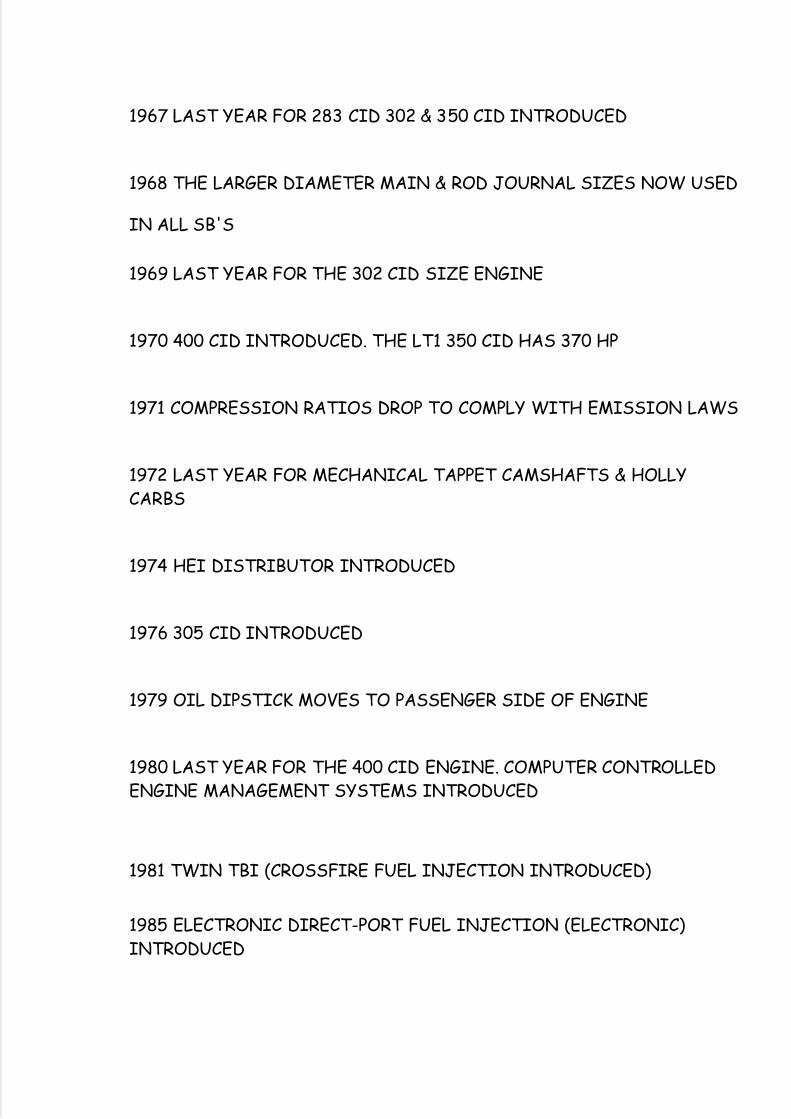
1967 LAST YEAR FOR 283 CID 302 & 350 CID INTRODUCED
1968 THE LARGER DIAMETER MAIN & ROD JOURNAL SIZES NOW USED
IN ALL SB'S
1969 LAST YEAR FOR THE 302 CID SIZE ENGINE
1970 400 CID INTRODUCED. THE LT1 350 CID HAS 370 HP
1971 COMPRESSION RATIOS DROP TO COMPLY WITH EMISSION LAWS
1972 LAST YEAR FOR MECHANICAL TAPPET CAMSHAFTS & HOLLYCARBS
1974 HEI DISTRIBUTOR INTRODUCED
1976 305 CID INTRODUCED
1979 OIL DIPSTICK MOVES TO PASSENGER SIDE OF ENGINE
1980 LAST YEAR FOR THE 400 CID ENGINE. COMPUTER CONTROLLEDENGINE MANAGEMENT SYSTEMS INTRODUCED
1981 TWIN TBI (CROSSFIRE FUEL INJECTION INTRODUCED)
1985 ELECTRONIC DIRECT-PORT FUEL INJECTION (ELECTRONIC)INTRODUCED
5/14/2018 Secrets of a Cam Designer - slidepdf.com
http://slidepdf.com/reader/full/secrets-of-a-cam-designer 26/40
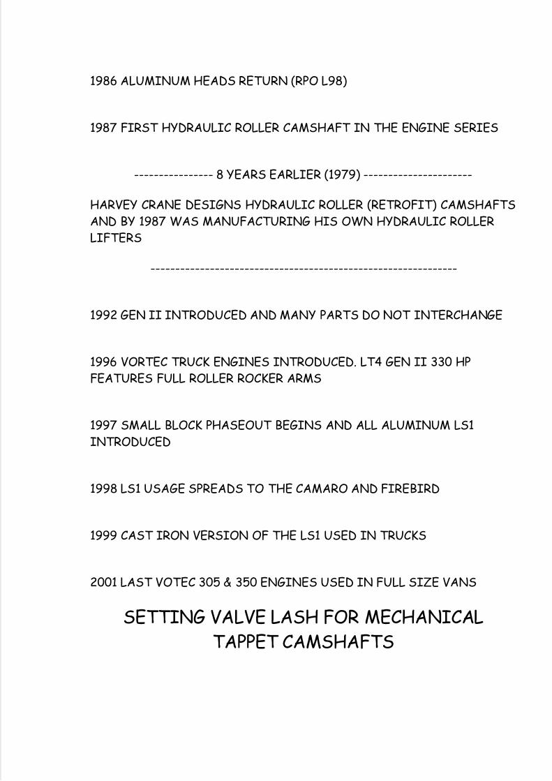
1986 ALUMINUM HEADS RETURN (RPO L98)
1987 FIRST HYDRAULIC ROLLER CAMSHAFT IN THE ENGINE SERIES
---------------- 8 YEARS EARLIER (1979) ----------------------
HARVEY CRANE DESIGNS HYDRAULIC ROLLER (RETROFIT) CAMSHAFTSAND BY 1987 WAS MANUFACTURING HIS OWN HYDRAULIC ROLLERLIFTERS
--------------------------------------------------------------
1992 GEN II INTRODUCED AND MANY PARTS DO NOT INTERCHANGE
1996 VORTEC TRUCK ENGINES INTRODUCED. LT4 GEN II 330 HPFEATURES FULL ROLLER ROCKER ARMS
1997 SMALL BLOCK PHASEOUT BEGINS AND ALL ALUMINUM LS1INTRODUCED
1998 LS1 USAGE SPREADS TO THE CAMARO AND FIREBIRD
1999 CAST IRON VERSION OF THE LS1 USED IN TRUCKS
2001 LAST VOTEC 305 & 350 ENGINES USED IN FULL SIZE VANS
SETTING VALVE LASH FOR MECHANICALTAPPET CAMSHAFTS
5/14/2018 Secrets of a Cam Designer - slidepdf.com
http://slidepdf.com/reader/full/secrets-of-a-cam-designer 27/40
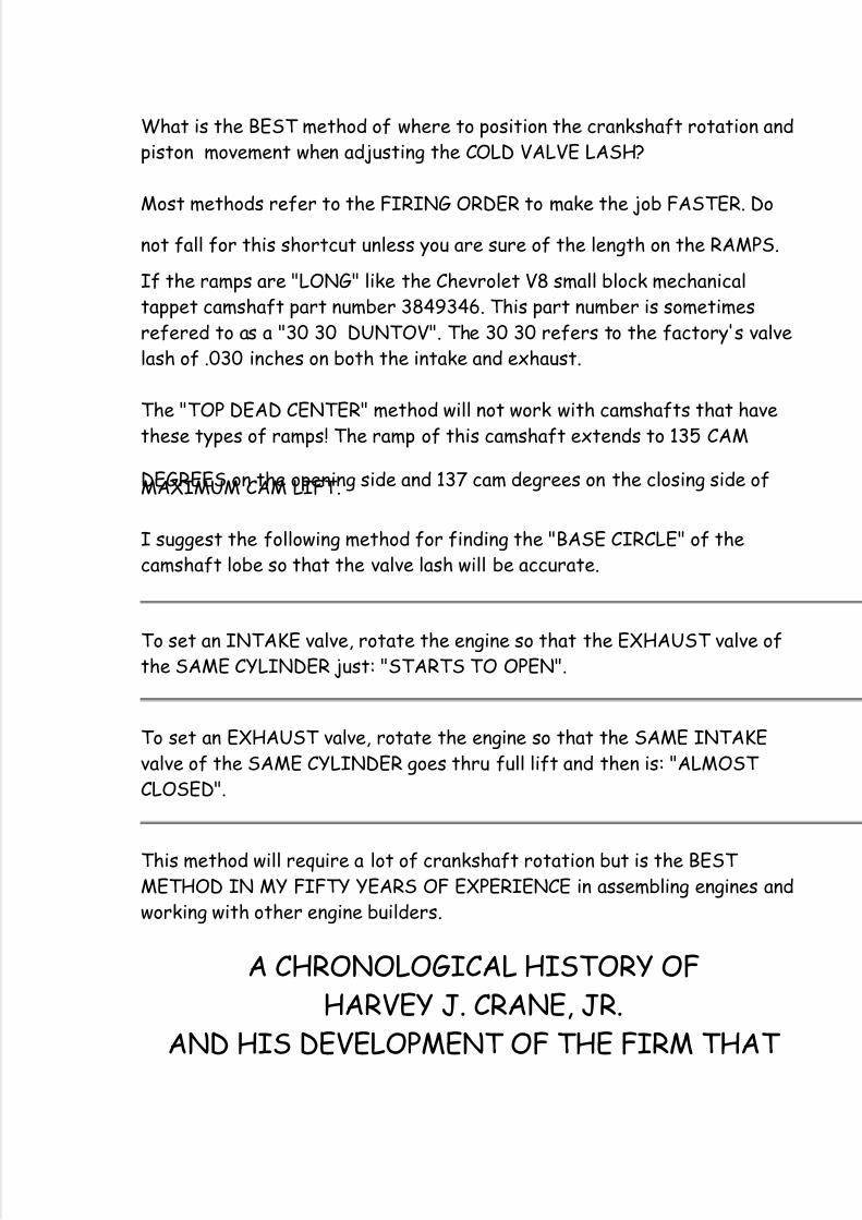
What is the BEST method of where to position the crankshaft rotation andpiston movement when adjusting the COLD VALVE LASH?
Most methods refer to the FIRING ORDER to make the job FASTER. Do
not fall for this shortcut unless you are sure of the length on the RAMPS.
If the ramps are "LONG" like the Chevrolet V8 small block mechanicaltappet camshaft part number 3849346. This part number is sometimesrefered to as a "30 30 DUNTOV". The 30 30 refers to the factory's valvelash of .030 inches on both the intake and exhaust.
The "TOP DEAD CENTER" method will not work with camshafts that havethese types of ramps! The ramp of this camshaft extends to 135 CAM
DEGREES on the opening side and 137 cam degrees on the closing side ofMAXIMUM CAM LIFT.
I suggest the following method for finding the "BASE CIRCLE" of thecamshaft lobe so that the valve lash will be accurate.
To set an INTAKE valve, rotate the engine so that the EXHAUST valve ofthe SAME CYLINDER just: "STARTS TO OPEN".
To set an EXHAUST valve, rotate the engine so that the SAME INTAKEvalve of the SAME CYLINDER goes thru full lift and then is: "ALMOST CLOSED".
This method will require a lot of crankshaft rotation but is the BEST METHOD IN MY FIFTY YEARS OF EXPERIENCE in assembling engines andworking with other engine builders.
A CHRONOLOGICAL HISTORY OFHARVEY J. CRANE, JR.
AND HIS DEVELOPMENT OF THE FIRM THAT

5/14/2018 Secrets of a Cam Designer - slidepdf.com
http://slidepdf.com/reader/full/secrets-of-a-cam-designer 28/40
STILL USES HIS LAST NAME TO PROMOTETHEIR PRODUCTS
START OF THE BUSINESS
1953 CRANE ENGINEERING COMPANY FOUNDED BY HARVEY J. CRANE,JR. AS THE SOLE OWNER. THE BUSINESS IS LOCATED IN 500SQUARE FEET, RENTED INSIDE HIS FATHERS GENERAL MACHINESHOP BUILDING.
10 YEARS LATER
1963 CRANE ENGINEERING CO, INC. A CORPORATION IS FORMED ANDHARVEY SELLS A 20% OWNERSHIP TO HIS HIGH SCHOOLFRIEND, DAVID SMITH, AND NAMES HIM AS SALES MANAGER.HARVEY CRANE RETAINS 80% OWNERSHIP.
1963 UNITED STATES PATENT NUMBER 3,108,580 IS ISSUED TOHARVEY J. CRANE, JR. (NEVER ASSIGNED TO THE CORPORATION)ON OCTOBER 29, 1963. THIS PATENT COVERS FOUR BASIC
CLAIMS ON A MECHANICAL ROLLER TAPPET DESIGN. THIS"SHIELDED ROLLER" TYPE DESIGN IS USED BY O.E.M.MANUFACTURERS FOR THEIR HYDRAULIC ROLLER TAPPETS 17YEARS LATER, (AFTER THE PATENT EXPIRES).
1965 HARVEY OUTGROWS HIS FATHERS SHOP AS 3,500 SQUARE FEET IS ALL HIS FATHER WILL RENT TO HIM. HE PURCHASES 8 LOTSIN HALLANDALE'S ONLY INDUSTRIAL ZONED AREA ANDCONSTRUCTS 15,000 SQUARE FEET. HE MOVES 35 EMPLOYEESINTO THE NEW PLANT IN JANUARY OF 1966. THIS PLANT WILL
EVENTUALLY BE ENLARGED TWICE, TO A TOTAL OF 35,000SQUARE FEET.
1965 FIRST COMPUTER ANALYSIS PERFORMED ON A HARVEY CRANEDESIGNED "DRAWING BOARD" CAM, BY J. H. NOURSE OFYPSILANATI, MICHIGAN.
1967 FIRST CAM PROFILE DESIGNED ON A COMPUTER BY HARVEYCRANE, USING A CAM DESIGN PROGRAM WRITTEN BY J. H.
5/14/2018 Secrets of a Cam Designer - slidepdf.com
http://slidepdf.com/reader/full/secrets-of-a-cam-designer 29/40
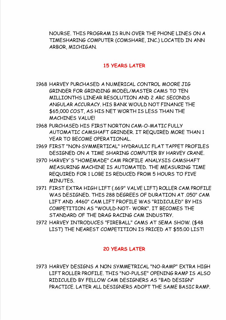
NOURSE. THIS PROGRAM IS RUN OVER THE PHONE LINES ON ATIMESHARING COMPUTER (COMSHARE, INC.) LOCATED IN ANNARBOR, MICHIGAN.
15 YEARS LATER
1968 HARVEY PURCHASED A NUMERICAL CONTROL MOORE JIGGRINDER FOR GRINDING MODEL/MASTER CAMS TO TENMILLIONTHS LINEAR RESOLUTION AND 2 ARC SECONDSANGULAR ACCURACY. HIS BANK WOULD NOT FINANCE THE$65,000 COST, AS HIS NET WORTH IS LESS THAN THEMACHINES VALUE!
1968 PURCHASED HIS FIRST NORTON CAM-O-MATIC FULLYAUTOMATIC CAMSHAFT GRINDER. IT REQUIRED MORE THAN 1YEAR TO BECOME OPERATIONAL.
1969 FIRST "NON-SYMMERTICAL" HYDRAULIC FLAT TAPPET PROFILESDESIGNED ON A TIME SHARING COMPUTER BY HARVEY CRANE.
1970 HARVEY'S "HOMEMADE" CAM PROFILE ANALYSIS CAMSHAFT MEASURING MACHINE IS AUTOMATED. THE MEASURING TIMEREQUIRED FOR 1 LOBE IS REDUCED FROM 5 HOURS TO FIVEMINUTES.
1971 FIRST EXTRA HIGH LIFT (.669" VALVE LIFT) ROLLER CAM PROFILEWAS DESIGNED. THIS 288 DEGREES OF DURATION AT .050" CAMLIFT AND .4460" CAM LIFT PROFILE WAS "RIDICULED" BY HISCOMPETITION AS "WOULD-NOT- WORK". IT BECOMES THESTANDARD OF THE DRAG RACING CAM INDUSTRY.
1972 HARVEY INTRODUCES "FIREBALL" CAMS AT SEMA SHOW. ($48LIST) THE NEAREST COMPETITION IS PRICED AT $55.00 LIST!
20 YEARS LATER
1973 HARVEY DESIGNS A NON SYMMETRICAL "NO-RAMP" EXTRA HIGHLIFT ROLLER PROFILE. THIS "NO-PULSE" OPENING RAMP IS ALSORIDICULED BY FELLOW CAM DESIGNERS AS "BAD DESIGN"PRACTICE. LATER ALL DESIGNERS ADOPT THE SAME BASIC RAMP.
5/14/2018 Secrets of a Cam Designer - slidepdf.com
http://slidepdf.com/reader/full/secrets-of-a-cam-designer 30/40
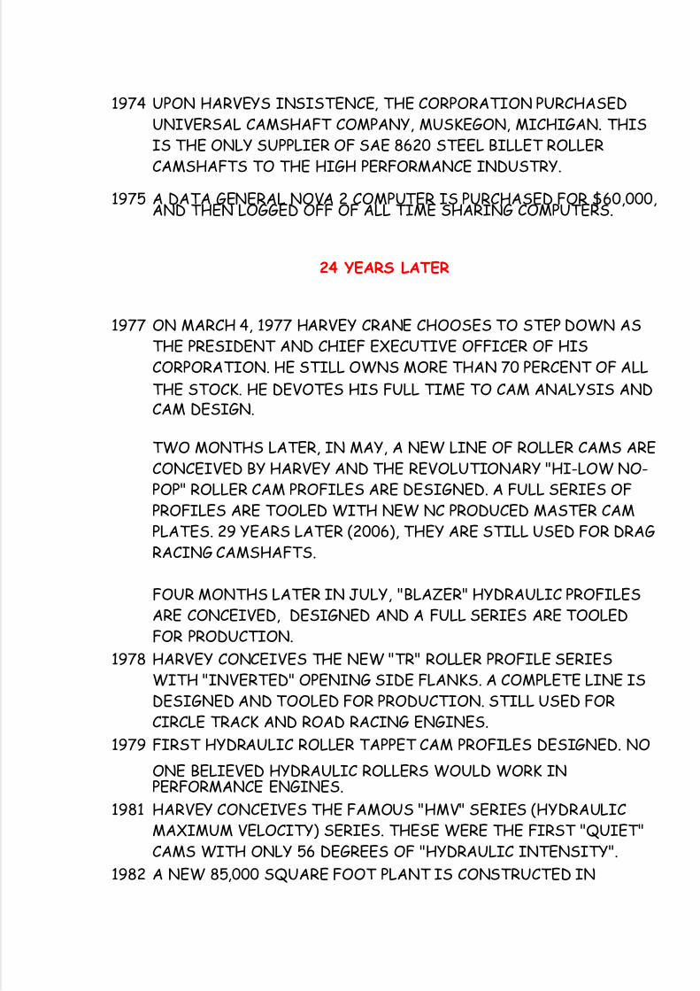
1974 UPON HARVEYS INSISTENCE, THE CORPORATION PURCHASEDUNIVERSAL CAMSHAFT COMPANY, MUSKEGON, MICHIGAN. THISIS THE ONLY SUPPLIER OF SAE 8620 STEEL BILLET ROLLERCAMSHAFTS TO THE HIGH PERFORMANCE INDUSTRY.
1975 A DATA GENERAL NOVA 2 COMPUTER IS PURCHASED FOR $60,000,AND THEN LOGGED OFF OF ALL TIME SHARING COMPUTERS.
24 YEARS LATER
1977 ON MARCH 4, 1977 HARVEY CRANE CHOOSES TO STEP DOWN ASTHE PRESIDENT AND CHIEF EXECUTIVE OFFICER OF HISCORPORATION. HE STILL OWNS MORE THAN 70 PERCENT OF ALL
THE STOCK. HE DEVOTES HIS FULL TIME TO CAM ANALYSIS ANDCAM DESIGN.
TWO MONTHS LATER, IN MAY, A NEW LINE OF ROLLER CAMS ARECONCEIVED BY HARVEY AND THE REVOLUTIONARY "HI-LOW NO-POP" ROLLER CAM PROFILES ARE DESIGNED. A FULL SERIES OFPROFILES ARE TOOLED WITH NEW NC PRODUCED MASTER CAMPLATES. 29 YEARS LATER (2006), THEY ARE STILL USED FOR DRAGRACING CAMSHAFTS.
FOUR MONTHS LATER IN JULY, "BLAZER" HYDRAULIC PROFILESARE CONCEIVED, DESIGNED AND A FULL SERIES ARE TOOLEDFOR PRODUCTION.
1978 HARVEY CONCEIVES THE NEW "TR" ROLLER PROFILE SERIESWITH "INVERTED" OPENING SIDE FLANKS. A COMPLETE LINE ISDESIGNED AND TOOLED FOR PRODUCTION. STILL USED FORCIRCLE TRACK AND ROAD RACING ENGINES.
1979 FIRST HYDRAULIC ROLLER TAPPET CAM PROFILES DESIGNED. NO
ONE BELIEVED HYDRAULIC ROLLERS WOULD WORK INPERFORMANCE ENGINES.
1981 HARVEY CONCEIVES THE FAMOUS "HMV" SERIES (HYDRAULICMAXIMUM VELOCITY) SERIES. THESE WERE THE FIRST "QUIET"CAMS WITH ONLY 56 DEGREES OF "HYDRAULIC INTENSITY".
1982 A NEW 85,000 SQUARE FOOT PLANT IS CONSTRUCTED IN
5/14/2018 Secrets of a Cam Designer - slidepdf.com
http://slidepdf.com/reader/full/secrets-of-a-cam-designer 31/40
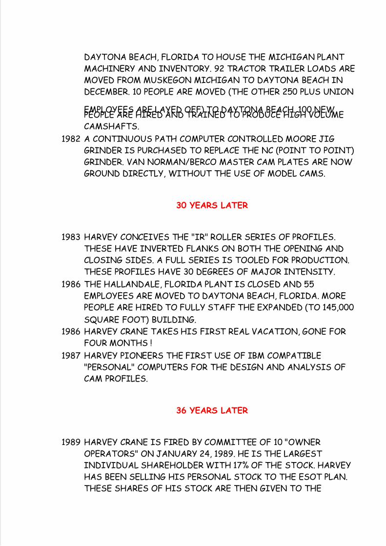
DAYTONA BEACH, FLORIDA TO HOUSE THE MICHIGAN PLANT MACHINERY AND INVENTORY. 92 TRACTOR TRAILER LOADS AREMOVED FROM MUSKEGON MICHIGAN TO DAYTONA BEACH INDECEMBER. 10 PEOPLE ARE MOVED (THE OTHER 250 PLUS UNION
EMPLOYEES ARE LAYED OFF) TO DAYTONA BEACH. 100 NEWPEOPLE ARE HIRED AND TRAINED TO PRODUCE HIGH VOLUMECAMSHAFTS.
1982 A CONTINUOUS PATH COMPUTER CONTROLLED MOORE JIGGRINDER IS PURCHASED TO REPLACE THE NC (POINT TO POINT)GRINDER. VAN NORMAN/BERCO MASTER CAM PLATES ARE NOWGROUND DIRECTLY, WITHOUT THE USE OF MODEL CAMS.
30 YEARS LATER
1983 HARVEY CONCEIVES THE "IR" ROLLER SERIES OF PROFILES.THESE HAVE INVERTED FLANKS ON BOTH THE OPENING ANDCLOSING SIDES. A FULL SERIES IS TOOLED FOR PRODUCTION.THESE PROFILES HAVE 30 DEGREES OF MAJOR INTENSITY.
1986 THE HALLANDALE, FLORIDA PLANT IS CLOSED AND 55EMPLOYEES ARE MOVED TO DAYTONA BEACH, FLORIDA. MOREPEOPLE ARE HIRED TO FULLY STAFF THE EXPANDED (TO 145,000
SQUARE FOOT) BUILDING.1986 HARVEY CRANE TAKES HIS FIRST REAL VACATION, GONE FOR
FOUR MONTHS !
1987 HARVEY PIONEERS THE FIRST USE OF IBM COMPATIBLE"PERSONAL" COMPUTERS FOR THE DESIGN AND ANALYSIS OFCAM PROFILES.
36 YEARS LATER
1989 HARVEY CRANE IS FIRED BY COMMITTEE OF 10 "OWNEROPERATORS" ON JANUARY 24, 1989. HE IS THE LARGEST INDIVIDUAL SHAREHOLDER WITH 17% OF THE STOCK. HARVEYHAS BEEN SELLING HIS PERSONAL STOCK TO THE ESOT PLAN.THESE SHARES OF HIS STOCK ARE THEN GIVEN TO THE
5/14/2018 Secrets of a Cam Designer - slidepdf.com
http://slidepdf.com/reader/full/secrets-of-a-cam-designer 32/40
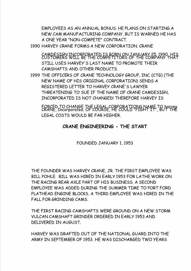
EMPLOYEES AS AN ANNUAL BONUS. HE PLANS ON STARTING ANEW CAM MANUFACTURING COMPANY, BUT IS WARNED HE HASA ONE YEAR "NON-COMPETE" CONTRACT.
1990 HARVEY CRANE FORMS A NEW CORPORATION. CRANE
CAMDESIGN INCORPORATED IS BORN ON JANUARY 25, 1990. HISCUSTOMERS WILL BE THE COMPETITORS OF THE COMPANY THAT STILL USES HARVEY'S LAST NAME TO PROMOTE THEIRCAMSHAFTS AND OTHER PRODUCTS.
1999 THE OFFICERS OF CRANE TECHNOLOGY GROUP, INC. (CTG) (THENEW NAME OF HIS ORIGINAL CORPORATION) SENDS AREGISTERED LETTER TO HARVEY CRANE'S LAWYERTHREATENING TO SUE IF THE NAME OF CRANE CAMDESIGN,INCORPORATED IS NOT CHANGED! THEREFORE HARVEY IS
FORCED TO CHANGE THE LEGAL CORPORATIONS NAME TO harveyCRANE, Incorporated. OF COURSE, HE COULD "FIGHT IT", BUT THELEGAL COSTS WOULD BE FAR HIGHER.
CRANE ENGINEERING - THE START
FOUNDED JANUARY 1, 1953
THE FOUNDER WAS HARVEY CRANE, JR. THE FIRST EMPLOYEE WASBILL POHLE. BILL WAS HIRED IN EARLY 1953 FOR LATHE WORK ONTHE RACING REAR AXLE PART OF HIS BUSINESS. A SECONDEMPLOYEE WAS ADDED DURING THE SUMMER TIME TO PORT FORDFLATHEAD ENGINE BLOCKS. A THIRD EMPLOYEE WAS HIRED IN THEFALL FOR GRINDING CAMS.
THE FIRST RACING CAMSHAFTS WERE GROUND ON A NEW STORMVULCAN CAMSHAFT GRINDER ORDERED IN EARLY 1953 ANDDELIVERED IN AUGUST.
HARVEY WAS DRAFTED OUT OF THE NATIONAL GUARD INTO THEARMY IN SEPTEMBER OF 1953. HE WAS DISCHARGED TWO YEARS
5/14/2018 Secrets of a Cam Designer - slidepdf.com
http://slidepdf.com/reader/full/secrets-of-a-cam-designer 33/40
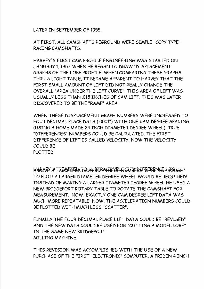
LATER IN SEPTEMBER OF 1955.
AT FIRST, ALL CAMSHAFTS REGROUND WERE SIMPLE "COPY TYPE"RACING CAMSHAFTS.
HARVEY'S FIRST CAM PROFILE ENGINEERING WAS STARTED ONJANUARY 1, 1957 WHEN HE BEGAN TO DRAW "DISPLACEMENT"GRAPHS OF THE LOBE PROFILE. WHEN COMPARING THESE GRAPHSTHRU A LIGHT TABLE, IT BECAME APPARENT TO HARVEY THAT THEFIRST SMALL AMOUNT OF LIFT DID NOT REALLY CHANGE THEOVERALL "AREA UNDER THE LIFT CURVE". THIS AREA OF LIFT WASUSUALLY LESS THAN .015 INCHES OF CAM LIFT. THIS WAS LATERDISCOVERED TO BE THE "RAMP" AREA.
WHEN THESE DISPLACEMENT GRAPH NUMBERS WERE INCREASED TOFOUR DECIMAL PLACE DATA (.0001") WITH ONE CAM DEGREE SPACING(USING A HOME MADE 24 INCH DIAMETER DEGREE WHEEL), TRUE"DIFFERENCES" NUMBERS COULD BE CALCULATED. THE FIRST DIFFERENCE OF LIFT IS CALLED VELOCITY. NOW THE VELOCITYCOULD BEPLOTTED!
HARVEY ATTEMPTED TO SUBTRACT VELOCITY DIFFERENCES TOARRIVE AT ACCELERATION BUT THESE NUMBERS WERE TO "ROUGH"TO PLOT! A LARGER DIAMETER DEGREE WHEEL WOULD BE REQUIRED!INSTEAD OF MAKING A LARGER DIAMETER DEGREE WHEEL HE USED ANEW BRIDGEPORT ROTARY TABLE TO ROTATE THE CAMSHAFT FORMEASUREMENT. NOW, EXACTLY ONE CAM DEGREE LIFT DATA WASMUCH MORE REPEATABLE. NOW, THE ACCELERATION NUMBERS COULDBE PLOTTED WITH MUCH LESS "SCATTER".
FINALLY THE FOUR DECIMAL PLACE LIFT DATA COULD BE "REVISED"AND THE NEW DATA COULD BE USED FOR "CUTTING A MODEL LOBE"IN THE SAME NEW BRIDGEPORT MILLING MACHINE.
THIS REVISION WAS ACCOMPLISHED WITH THE USE OF A NEWPURCHASE OF THE FIRST "ELECTRONIC" COMPUTER, A FRIDEN 4 INCH
5/14/2018 Secrets of a Cam Designer - slidepdf.com
http://slidepdf.com/reader/full/secrets-of-a-cam-designer 34/40
SCREEN FOUR FUNCTION CALCULATOR.
SO MUCH FOR PROGRESS!
CAM SCHOOL BOOK INDEX
AS OF FEBRUARY 20, 2006
PAGE# SUBJECT
1..BACKGROUND TO THIS CLASS
2..SUBJECTS TO BE COVERED3..DETAILS OF SUBJECT NUMBERS 1 THRU 44..DETAILS OF SUBJECT NUMBERS 5 THRU 115..NEW TECHNIQUES IN CAM PROFILE DESIGN6..EXCERPT FROM "COSWORTH THE SEARCH FOR POWER" (PUBLISHED1990)7..HARVEY CRANE'S BIOGRAPHY8..CRANE ENGINEERING COMPANY, A HISTORY FROM 1953 THRU 19659..CHRONOLOGICAL HISTORY OF HJC'S DEVELOPMENT OF HIS
COMPANY10..CHRONOLOGICAL HISTORY OF HJC'S DEVELOPMENT OF HISCOMPANY11..CHRONOLOGICAL HISTORY OF HJC'S DEVELOPMENT OF HISCOMPANY12..A HISTORY OF INDEPENDENT CAMSHAFT MANUFACTURERS13..A HISTORY OF INDEPENDENT CAMSHAFT MANUFACTURERS14..A HISTORY OF INDEPENDENT CAMSHAFT MANUFACTURERS15..A HISTORY OF INDENPENDENT CAMSHAFT MANUFACTURERS
16..ED WINFIELD, HIS HISTORY AS A CAMSHAFT MANUFACTURER BYHJC17..ED WINFIELD, AS TOLD BY DEMA ELGIN18..THE BERCO CAM GRINDER AND ITS ORIGIN19..harvey CRANE, Incorporated's CamCheck MACHINE NUMBER 120..PATENTS ABOUT CAM DESIGNS AND LOBE SHAPES 1916 THRU 195121..PATENTS ABOUT CAM DESIGNS AND LOBE SHAPES 1953 THRU 1978

5/14/2018 Secrets of a Cam Designer - slidepdf.com
http://slidepdf.com/reader/full/secrets-of-a-cam-designer 35/40
22..BOOKS ABOUT CAMSHAFTS (GOOD ONES ONLY)23..TAPPET SIZE AND MAXIMUM VELOCITY (0.748" THRU 0.999"DIAMETER)24..TAPPET SIZE AND MAXIMUM VELOCITY (1.102" THRU 1.378"
DIAMETER)25..TAPPET SIZE AND MAXIMUM VELOCITY (1.415" THRU 1.808"DIAMETER)26..THE CAM DOCTOR (1998 PRICING AND OPTIONS LISTING)27..VALVE SPRING MANUFACTURERS AND RESELLERS28..FILE EXTENSION NAMES (AS RECOMMENDED BY HARVEY CRANE)29..CAM PROFILE INTENSITY AND SPAN30..CAM PROFILE INTENSITY AND SPAN31..CAM PROFILE INTENSITY AND SPAN
32..CAM PROFILE MEASURING MACHINES AND RESELLERS33..THE CAM DOCTOR MEASURING PROBLEMS AND SOLUTIONS34..VALVE TIMING DIAGRAMS, HOW THEY CAN LIE TO YOU35..VALVE TIMING DIAGRAMS, CONTINUED36..TRIPLE VALVE SPRINGS, A HISTORY AND TRADEMARKS37..HARVEY'S EX EMPLOYEES AND THEIR NEW FIRMS OR EMPLOYERS38..RAMP SECRETS (PAGE ONE)39..RAMP SECRETS (PAGE TWO)40..RAMP SECRETS (PAGE THREE)
41..RAMP SECRETS (INTENSITY DATA)42/55..GRAPHS OF THE ABOVE RAMP TYPES (13 PAGES TOTAL)
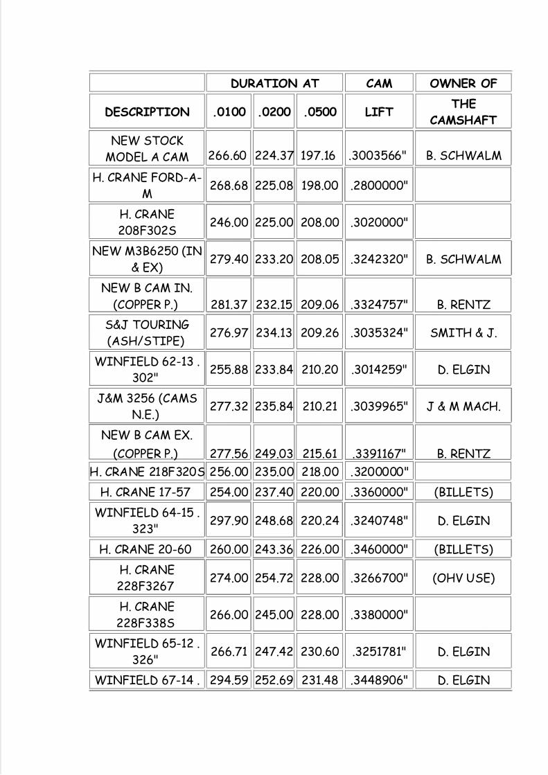
FORD MODEL A & MODEL B
AVERAGE OF SEVERAL LOBES (ACTUALLY MEASURED INHARVEY CRANE'S $100,000 MEASURING MACHINE #1) ANDTHE PROFILEA.EXE ANALYSIS OF FLATHEAD (AND SOME
OHV/FLATHEAD) REGROUND CAMSHAFTS. PLUS ALLDESIGN DATA FOR REGRINDS AND BILLET CAMS LISTEDIN ORDER OF .0500" DURATION
5/14/2018 Secrets of a Cam Designer - slidepdf.com
http://slidepdf.com/reader/full/secrets-of-a-cam-designer 36/40
DURATION AT CAM OWNER OF
DESCRIPTION .0100 .0200 .0500 LIFTTHE
CAMSHAFT
NEW STOCKMODEL A CAM 266.60 224.37 197.16 .3003566" B. SCHWALM
H. CRANE FORD-A-M
268.68 225.08 198.00 .2800000"
H. CRANE208F302S
246.00 225.00 208.00 .3020000"
NEW M3B6250 (IN& EX)
279.40 233.20 208.05 .3242320" B. SCHWALM
NEW B CAM IN.(COPPER P.) 281.37 232.15 209.06 .3324757" B. RENTZ
S&J TOURING(ASH/STIPE)
276.97 234.13 209.26 .3035324" SMITH & J.
WINFIELD 62-13 .302"
255.88 233.84 210.20 .3014259" D. ELGIN
J&M 3256 (CAMSN.E.)
277.32 235.84 210.21 .3039965" J & M MACH.
NEW B CAM EX.
(COPPER P.) 277.56 249.03 215.61 .3391167" B. RENTZ
H. CRANE 218F320S 256.00 235.00 218.00 .3200000"
H. CRANE 17-57 254.00 237.40 220.00 .3360000" (BILLETS)
WINFIELD 64-15 .323"
297.90 248.68 220.24 .3240748" D. ELGIN
H. CRANE 20-60 260.00 243.36 226.00 .3460000" (BILLETS)
H. CRANE228F3267
274.00 254.72 228.00 .3266700" (OHV USE)
H. CRANE228F338S
266.00 245.00 228.00 .3380000"
WINFIELD 65-12 .326"
266.71 247.42 230.60 .3251781" D. ELGIN
WINFIELD 67-14 . 294.59 252.69 231.48 .3448906" D. ELGIN
5/14/2018 Secrets of a Cam Designer - slidepdf.com
http://slidepdf.com/reader/full/secrets-of-a-cam-designer 37/40
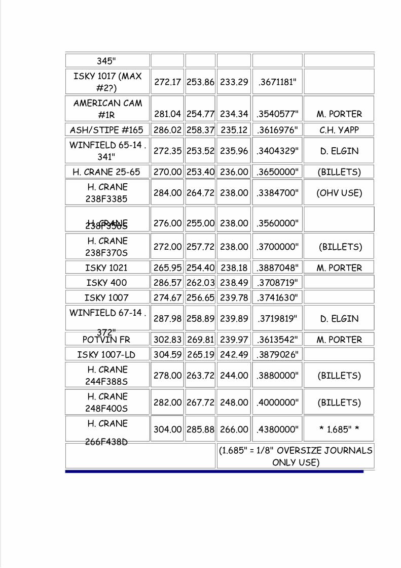
345"
ISKY 1017 (MAX#2?)
272.17 253.86 233.29 .3671181"
AMERICAN CAM#1R 281.04 254.77 234.34 .3540577" M. PORTER
ASH/STIPE #165 286.02 258.37 235.12 .3616976" C.H. YAPP
WINFIELD 65-14 .341"
272.35 253.52 235.96 .3404329" D. ELGIN
H. CRANE 25-65 270.00 253.40 236.00 .3650000" (BILLETS)
H. CRANE238F3385
284.00 264.72 238.00 .3384700" (OHV USE)
H. CRANE238F356S 276.00 255.00 238.00 .3560000"
H. CRANE238F370S
272.00 257.72 238.00 .3700000" (BILLETS)
ISKY 1021 265.95 254.40 238.18 .3887048" M. PORTER
ISKY 400 286.57 262.03 238.49 .3708719"
ISKY 1007 274.67 256.65 239.78 .3741630"
WINFIELD 67-14 .
372"
287.98 258.89 239.89 .3719819" D. ELGIN
POTVIN FR 302.83 269.81 239.97 .3613542" M. PORTER
ISKY 1007-LD 304.59 265.19 242.49 .3879026"
H. CRANE244F388S
278.00 263.72 244.00 .3880000" (BILLETS)
H. CRANE248F400S
282.00 267.72 248.00 .4000000" (BILLETS)
H. CRANE
266F438D
304.00 285.88 266.00 .4380000" * 1.685" *
(1.685" = 1/8" OVERSIZE JOURNALS
ONLY USE)
5/14/2018 Secrets of a Cam Designer - slidepdf.com
http://slidepdf.com/reader/full/secrets-of-a-cam-designer 38/40
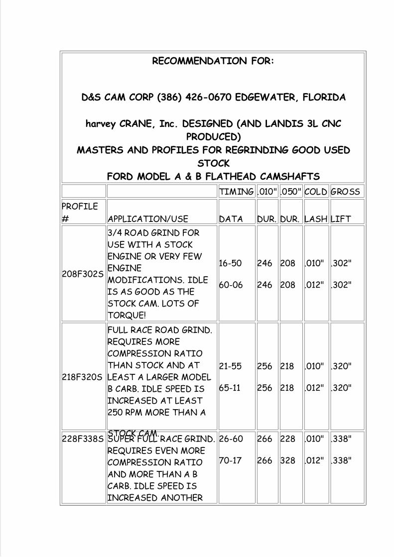
RECOMMENDATION FOR:
D&S CAM CORP (386) 426-0670 EDGEWATER, FLORIDA
harvey CRANE, Inc. DESIGNED (AND LANDIS 3L CNCPRODUCED)
MASTERS AND PROFILES FOR REGRINDING GOOD USEDSTOCK
FORD MODEL A & B FLATHEAD CAMSHAFTS
TIMING .010" .050" COLD GROSS
PROFILE
# APPLICATION/USE DATA DUR. DUR. LASH LIFT
208F302S
3/4 ROAD GRIND FORUSE WITH A STOCKENGINE OR VERY FEWENGINEMODIFICATIONS. IDLEIS AS GOOD AS THESTOCK CAM. LOTS OFTORQUE!
16-50
60-06
246
246
208
208
.010"
.012"
.302"
.302"
218F320S
FULL RACE ROAD GRIND.REQUIRES MORECOMPRESSION RATIOTHAN STOCK AND AT LEAST A LARGER MODELB CARB. IDLE SPEED ISINCREASED AT LEAST 250 RPM MORE THAN A
STOCK CAM.
21-55
65-11
256
256
218
218
.010"
.012"
.320"
.320"
228F338S SUPER FULL RACE GRIND.REQUIRES EVEN MORECOMPRESSION RATIOAND MORE THAN A BCARB. IDLE SPEED ISINCREASED ANOTHER
26-60
70-17
266
266
228
328
.010"
.012"
.338"
.338"
5/14/2018 Secrets of a Cam Designer - slidepdf.com
http://slidepdf.com/reader/full/secrets-of-a-cam-designer 39/40
200 RPM OVER THE 218PROFILE.
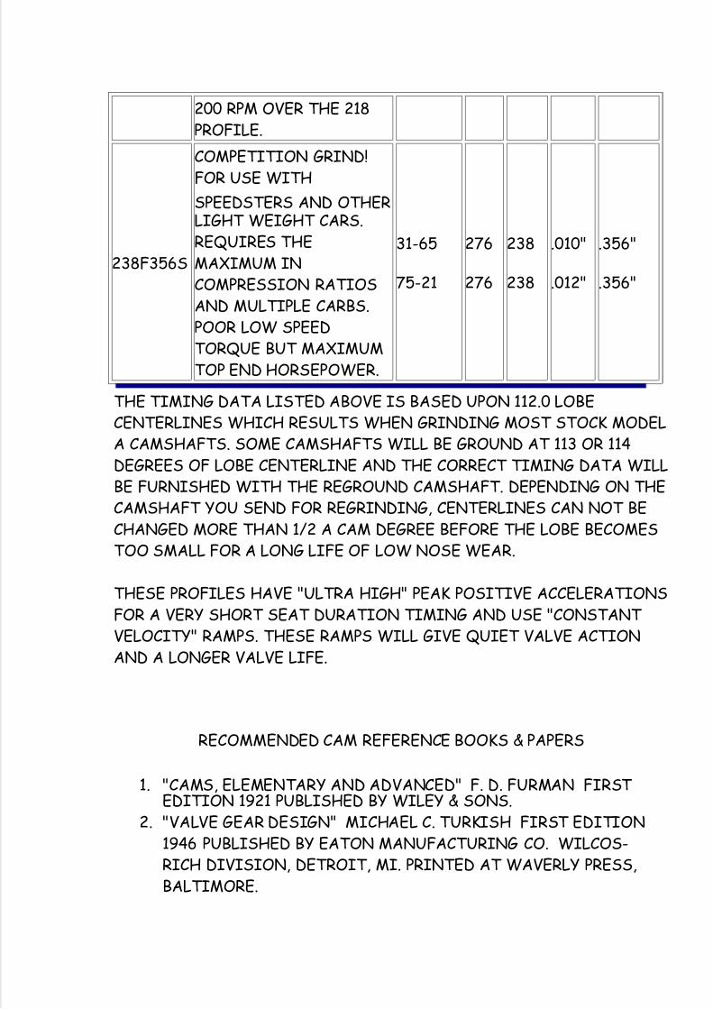
238F356S
COMPETITION GRIND!FOR USE WITH
SPEEDSTERS AND OTHERLIGHT WEIGHT CARS.REQUIRES THEMAXIMUM INCOMPRESSION RATIOSAND MULTIPLE CARBS.POOR LOW SPEEDTORQUE BUT MAXIMUMTOP END HORSEPOWER.
31-65
75-21
276
276
238
238
.010"
.012"
.356"
.356"
THE TIMING DATA LISTED ABOVE IS BASED UPON 112.0 LOBECENTERLINES WHICH RESULTS WHEN GRINDING MOST STOCK MODELA CAMSHAFTS. SOME CAMSHAFTS WILL BE GROUND AT 113 OR 114DEGREES OF LOBE CENTERLINE AND THE CORRECT TIMING DATA WILLBE FURNISHED WITH THE REGROUND CAMSHAFT. DEPENDING ON THECAMSHAFT YOU SEND FOR REGRINDING, CENTERLINES CAN NOT BECHANGED MORE THAN 1/2 A CAM DEGREE BEFORE THE LOBE BECOMESTOO SMALL FOR A LONG LIFE OF LOW NOSE WEAR.
THESE PROFILES HAVE "ULTRA HIGH" PEAK POSITIVE ACCELERATIONSFOR A VERY SHORT SEAT DURATION TIMING AND USE "CONSTANT VELOCITY" RAMPS. THESE RAMPS WILL GIVE QUIET VALVE ACTIONAND A LONGER VALVE LIFE.
RECOMMENDED CAM REFERENCE BOOKS & PAPERS
1. "CAMS, ELEMENTARY AND ADVANCED" F. D. FURMAN FIRST EDITION 1921 PUBLISHED BY WILEY & SONS.
2. "VALVE GEAR DESIGN" MICHAEL C. TURKISH FIRST EDITION1946 PUBLISHED BY EATON MANUFACTURING CO. WILCOS-RICH DIVISION, DETROIT, MI. PRINTED AT WAVERLY PRESS,BALTIMORE.

5/14/2018 Secrets of a Cam Designer - slidepdf.com
http://slidepdf.com/reader/full/secrets-of-a-cam-designer 40/40
3. "NEW METHODS OF VALVE TRAIN DESIGN" W. M. DUDLEYJANUARY 2, 1948 SAE TRANSACTIONS
4. "POLYDYNE CAM DESIGN" D. A. STODDART JANUARY 1953MACHINE DESIGN #25 FEBURARY 1953 & MARCH 1953
5. "CAMS" H. A. ROTHBART 1956 PUBLISHED BY WILEY & SONS.6. "CAM DESIGN HANDBOOK" 2003 HAROLD A. ROTHBART, 23825
ANZA AVENUE #127, TORRANCE, CA, 90505, USA PUBLISHED BYMcGRAW HILL
7. "SECRETS OF A CAM DESIGNER" HARVEY J. CRANE, JR.AVAILABLE ONLY AS A RESULT OF ATTENDING HARVEY'S CAMSCHOOL