secondary containment - official website beth.pdf · secondary containment ... • 1320 gallons of...
TRANSCRIPT

Secondary Containment
Beth Powell VP & General Manager
855-PIG-LINER (744-5463) www.newpigenergy.com

Regulations
EPA
Liquids
PA DEP
and Best Practices
API MSC
STRONGER Advisory Commissions & Boards

Federal Secondary Containment
Safeguarding method in addition to the primary containment system
Specific/Sized – Indoor: Sump capacity should contain 10% of the volume of total
containers or the total volume of the largest container, whichever is greater
– Outdoor: Plus sufficient freeboard to contain precipitation
General – Address typical failure mode and the most likely quantity – Passive or Active

SPCC Spill Prevention, Control, and Countermeasure (SPCC)
– 40 CFR 112
– Monitors plans to prevent oil spills at facilities
• Oil, oil-like and oil/water mixtures
• 1320 gallons of above-ground storage capacity
• Potential to reach “navigable waters”
• Defines oil pollution as a “sheen” on the water
– Clarifies “facility”; can be considered mobile or portable
– Sets compliance date of November 10, 2011 for facilities that came into operation after August 12, 2002
http://www.epa.gov/osweroe1/docs/oil/spcc/spcc_101_prod.pdf

SPCC 40CFR112.7(c) The entire containment system, including walls and floor, must be capable of containing oil and must be constructed so that any discharge from a primary containment system, such as a tank or pipe, will not escape the containment system before cleanup occurs. At a minimum, you must use one of the following prevention systems or its
equivalent: (1) For onshore facilities:
(i) Dikes, berms, or retaining walls sufficiently impervious to contain oil; (ii) Curbing; (iii) Culverting, gutters, or other drainage systems; (iv) Weirs, booms, or other barriers; (v) Spill diversion ponds; (vi) Retention ponds; or (vii) Sorbent materials.

If you are the owner or operator of an onshore oil drilling and workover facility, you must:
(a) Meet the general requirements listed under §112.7, and also meet the specific discharge prevention and containment procedures listed under this section.
(b) Position or locate mobile drilling or workover equipment so as to prevent a discharge as described in §112.1(b).
(c) Provide catchment basins or diversion structures to intercept and contain discharges of fuel, crude oil, or oily drilling fluids.
(d) Install a blowout prevention (BOP) assembly and well control system before drilling below any casing string or during workover operations. The BOP assembly and well control system must be capable of controlling any well-head pressure that may be encountered while that BOP assembly and well control system are on the well.
SPCC § 112.10 Provisions

SPCC Examples Methods Description of Secondary Containment Examples
Dikes, berms, or retaining walls sufficiently impervious to contain oil
Raised earth embankments or concrete containment walls used in areas with potential for large discharges, such as single or multiple aboveground storage tanks and certain piping.
Curbing Permanent concrete or asphalt apron surrounded by a curb. Can be used where only small spills are expected and also used to direct spills to drains or catchment areas.
Culverting, gutters, or other drainage systems
Types of permanent drainage systems designed to direct spills to remote containment or treatment areas.
Weirs Dam-like structures with a notch through which oil may flow to be collected. Used in combination with skimmers to remove oil from the surface of water.
Booms Form a continuous barrier placed as a precautionary measure to contain/collect oil. Typically used for the containment, exclusion, or deflection of oil floating on water, and is usually used to address oil spills that have reached surface waters.
Barriers Spill mats, storm drain covers, and dams used to block or prevent the flow of oil.
Spill diversion and retention ponds Designed for long-term or permanent containment of storm water capable to capture and hold oil or runoff and prevent it from entering surface water bodies.
Sorbent materials
Materials include spill pads, pillows, socks, mats, clay, vermiculite, and diatomaceous earth. Used to isolate and contain small drips or leaks until the source of the leak is repaired.
Drip pans
Used to isolate and contain small drips or leaks until the source of the leak is repaired. Drip pans are commonly used with product dispensing containers (usually drums), uncoupling of hoses during bulk transfer operations, and for pumps, valves, and fittings.
Sumps and collection systems A permanent pit or reservoir and the troughs/trenches connected to it that collect oil.

RCRA
Resource Conservation & Recovery Act (RCRA) – 40 CFR 260-265 (generator standards)
– Restricts hazardous waste collection and storage
– Defines “characteristic” and “listed” hazardous wastes
• Ignitability
• Corrosivity
• Reactivity
• Toxicity
– Exempts flowback fluids at federal level (state laws may apply)
– May not exempt fracturing fluids at federal level

NPDES National Pollutant Discharge Elimination System (NPDES)
– 40 CFR 122
– Limits water pollution through permits
– Delegates permitting to states; all Marcellus/Utica Shale states have received delegation
– Regulates stormwater discharges from construction sites (1 acre plus), industrial facilities and municipalities
– Considers sediment to be the most common pollutant
– Requires E&P sites to have sediment controls
– Defines oil pollution as a “sheen” on the water

API Recommend Practice
Environmental Protection for Onshore Oil and Gas Production Operations and Leases (51R)
– Containment should be constructed so spilled fuels or chemicals do not reach the ground
– Control the spread to the smallest possible area
• Drip pans under equipment and storage containers
• Retaining walls or dikes around tanks and other spill prone equipment
• Secondary catchment basins
• Permanent booms in the adjoining water basin
• Temporary booms deployed after the spill occurs
• Cleanup materials sufficient to handle small spills stocked on site

API Guidance Document
Practices for Mitigating Surface Impacts Associated with Hydraulic Fracturing (HF3)
– Spill prevention, response and cleanup procedures as part of SOP manual for storing oil, chemicals or other fluids
– Installation of containment, BMPs, barriers and response equipment
• Sloping well location away from surface water
• Retaining walls or dikes around tanks
• Secondary catchment basins
• Absorbent between sites and surface waters
• Temporary containment and liners during drilling and completions

PA DEP
Oil & Gas Act Clean Streams Law Solid Waste Management Act Prevention, Preparedness and Contingency (PPC) Plan • 25 Pa. Code §§ 78.55 Control and Disposal Plan
• 25 Pa. Code §§ 91.34 Activities Utilizing Pollutants
• Spills of 5 gallons or greater are reportable

Oil & Gas Spill Policy Draft
• Report a spill or release regardless of the quantity spilled
• If secondary containment is in place, notify if the quantity of material
exceeds 42 gallons
• Remove the spilled material from the secondary containment within
24 hours
• When spilled onto the ground, the material is usually either residual
waste or hazardous waste

PA Act 13 of 2012 The environmental protection provisions are effective April 16, 2012.
Unconventional well sites must be designed and constructed to prevent spills to the ground surface or off the well site. Containment practices must be in place during both drilling and hydraulic fracturing operations and must be sufficiently impervious and able to contain spilled materials, and be compatible with the waste material or waste stored within the containment. Containment plans must be submitted to the department and describe any equipment that is to be kept onsite to prevent a spill from leaving the well pad.
Containment systems shall be used wherever drilling mud, hydraulic oil, diesel fuel, drilling mud additives, hydraulic fracturing additives, and/or hydraulic fracturing flowback are stored. Containment areas must be sufficient to hold the volume of the largest container stored in the area plus ten percent. (§3218.2 of the Act)
http://files.dep.state.pa.us/OilGas/OilGasLandingPageFiles/Act13/Act_13_FAQ.pdf

Master Containment Plans Required for unconventional well permits starting October 14, 2012. Serves as the Department's Regional reference resource for all containment systems that may be used as part of an operator's containment practice for any well site within that Oil & Gas Region where drilling and hydraulic fracturing shall occur. Minimum: The containment plans must identify specific containment practices and specific containment systems to provide adequate containment for drilling muds, hydraulic oil, diesel fuel, drilling mud additives, hydraulic fracturing additives and hydraulic fracturing flowback. Shall Include:
1) General well site construction plans with expected containment systems placement 2) Overall containment practice 3) Detailed installation, utilization, integration and maintenance plan 4) Manufacturer's specifications on materials used, installation directions, maintenance
requirements, chemical compatibility, warranted uses and reuse/disposal considerations 5) List of all equipment that may be onsite that could be used to prevent/contain a spill 6) Name, address and contact information of the companies contracted by the operator that
may assist with spill response, containment and remediation
http://www.portal.state.pa.us/portal/server.pt/community/act_13/20789/act_13_faq/1127392
System vs. Practice A system is a type of containment method.
Examples: • Well pad lining system • Manifolded pallet-style secondary containment system
A practice is the specific way in which a containment system is used.
Examples: • A liner (system) used just under the drilling rig as localized containment (practice) • A liner (system) installed to cover the entire well site for complete containment (practice)
http://www.portal.state.pa.us/portal/server.pt/community/act_13/20789/act_13_faq/1127392

Containment System Examples
• Diking (Diking Fields) • Curbing or berming • Double-walled tanks • Open-top tanks and containers • Manifold containment tanking systems • Portable collapsible containment systems • Liquid transfer containment kits • Modular spill decks • Pipe sleeves • Surface liners • Sub-surface liners • Permitted centralized impoundments • Pits and impoundments that meet the design standards in 78.56 and 78.62 for the containment of pollutional substances • Spill kits, booms, and absorbent pads, mats, pillows and socks
http://www.portal.state.pa.us/portal/server.pt/community/act_13/20789/act_13_faq/1127392
Local Containment Practice Deployed only at the site of the reservoir (tanks), such as diesel fuel tanks, chemical tanks, roll offs, drilling rigs and trucking transfer stations.
These systems may also include using a spill deck under all chemical storage tanks of a certain size or deploying a collapsible portable containment system around all diesel fuel tanks.
These could also consist of any impermeable container made of a material that is compatible with the waste stored or used within the containment. Any containment material that meets the coefficient of permeability of no greater than 1 x 10⁻¹⁰ cm/sec and has supporting documentation of the permeability, chemical compatibility and other applicable QA/QC standards, is acceptable for use for containment.
If localized subsurface liners are used, departmental staff can require that sections of the liner be removed for inspection and sampling if a spill occurred. This is to ensure that the liner prevented a release onto the ground or into the waters of the Commonwealth.
http://www.portal.state.pa.us/portal/server.pt/community/act_13/20789/act_13_faq/1127392

Complete Containment Practice Complete containment is deployed under the entire well pad operation. Choose a liner that is
– Durable--Able to support the weight of heavy equipment, such as drilling rigs and trucks.
– Impervious--Constructed from a synthetic material with a coefficient of permeability of no greater than 1 x 10⁻¹⁰ cm/sec and with sufficient strength and thickness to maintain the integrity of the liner.
– Chemically Compatible--Designed, constructed and maintained so that the physical and chemical characteristics of the liner are not adversely affected by the waste and the liner is resistant to physical, chemical and other failure during transportation, handling, installation and use.
http://www.portal.state.pa.us/portal/server.pt/community/act_13/20789/act_13_faq/1127392
Complete Containment Practice
Other Lessons Learned:
• Verify that adjoining sections of liners are sealed together to prevent leakage in accordance with the manufacturer's directions.
• Design the liner system and site grade to efficiently collect and remove spilled material, waste and rainwater.
• Ensure the berming meets the permeability standard.
• Ensure the timely and quality repair of damage that is caused to any containment systems including, but not limited to: tears, punctures or any condition that compromises the maximum permeability requirements of the liner system.
http://www.portal.state.pa.us/portal/server.pt/community/act_13/20789/act_13_faq/1127392

Well Site Containments Pad
– Large square footage, typically centered off the wellheads – 6 to 8 inch high berms
Tank – 110% (150% in WV) of the largest tank – 18 to 36 inch high berms
Equipment – Placed under equipment that is leak prone – 6 to 8 inch high berms

Pad Containment
Work surfaces should be as clean and dry as possible to prevent slips and falls. Tip: Cover polyethylene liners in felt to increase the coefficient of friction. Tip: Limit wrinkled, loose layers of material to reduce tripping hazards.
OSHA 29 CFR 1910.22 SPCC 40 CFR 112.7 NPDES 40 CFR 122.26 RCRA 40 CFR 264.175

Composite Pad Liners
Composite liners are slip resistant and 5X more puncture resistant. Tip: Withstands rigging up and down.
Tip: Able to last through multiple operations.
Tip: Holes are readily detectable and easily repairable.
Tip: Recyclable to reduce 93% of landfill burden. OSHA 29 CFR 1910.22 SPCC 40 CFR 112.7 NPDES 40 CFR 122.26 RCRA 40 CFR 264.175
New Pig Patents Pending

Pad Subbase
Avoid mud. Tip: Cement dirt should be capped with at least 2 inches of stone. Tip: Stone should firm (no rolling or pumping) and rolled. Tip: Stone should be 2 inches or less in diameter. 2A Modified is preferred. River rock may develop rutts.

Seam Welding
Automated wedge welders should be used for all liners to join large panels together. Tip: Set to correct temperature and speed depending on liner and site conditions. Tip: Liner should be spotted during welding. OSHA 29 CFR 1910.22 SPCC 40 CFR 112.7 NPDES 40 CFR 122.26 RCRA 40 CFR 264.175

Leak Testing
Split welder seams can be tested by pressure. Solid wedge welder seams can be tested by air lance and vacuum. Tip: Vacuum tester can be moved 30 inches every 10 seconds.
OSHA 29 CFR 1910.22 SPCC 40 CFR 112.7 NPDES 40 CFR 122.26 RCRA 40 CFR 264.175

Patching
Plastic Liner: 1) Dry surface 2) Heat tack patch 3) Grind edge 4) Extrusion weld Composite Liner: 1) Dry surface 2) Surround with sealant 3) Heat tack patch 4) Surround with sealant
OSHA 29 CFR 1910.22 SPCC 40 CFR 112.7 NPDES 40 CFR 122.26 RCRA 40 CFR 264.175

Attachment to Cellar
Prevents leak in cellar from backing up under the liner. Tip: Can be mechanically attached or spray coated with polyurea.
OSHA 29 CFR 1910.22 SPCC 40 CFR 112.7 NPDES 40 CFR 122.26 RCRA 40 CFR 264.175
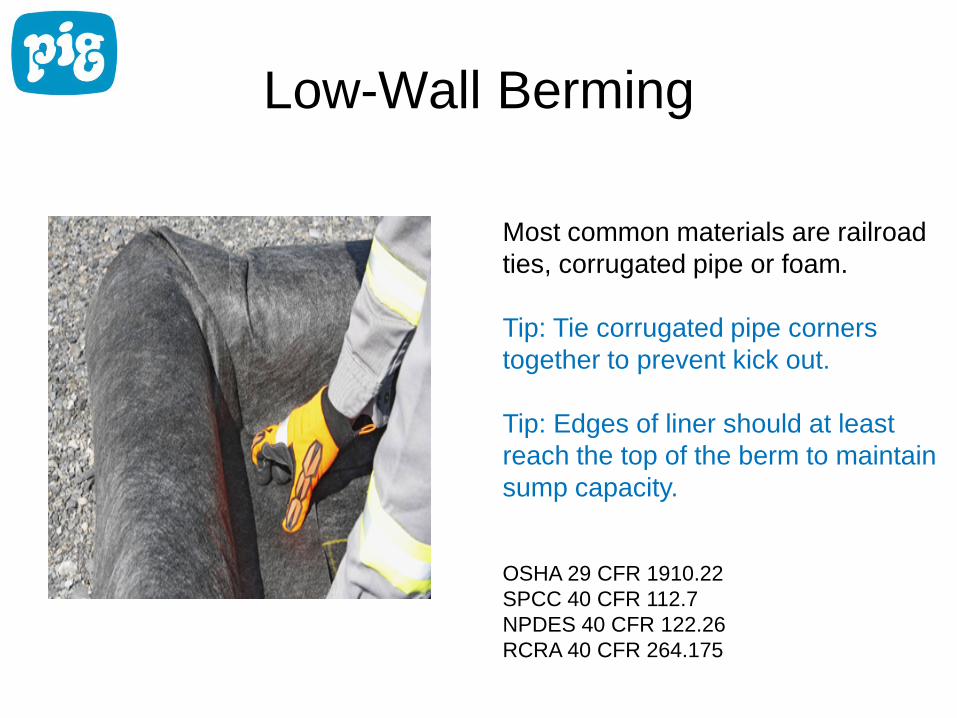
Low-Wall Berming
Most common materials are railroad ties, corrugated pipe or foam. Tip: Tie corrugated pipe corners together to prevent kick out. Tip: Edges of liner should at least reach the top of the berm to maintain sump capacity.
OSHA 29 CFR 1910.22 SPCC 40 CFR 112.7 NPDES 40 CFR 122.26 RCRA 40 CFR 264.175

Maintaining the Berm
Control access to either ramps or foam berms. Tip: Don’t park on the berm. Tip: Don’t cut away the berm. Tip: Plastic barricades seem to have the most success in limiting traffic.
OSHA 29 CFR 1910.22 SPCC 40 CFR 112.7 NPDES 40 CFR 122.26 RCRA 40 CFR 264.175

Grounding Rods
Ideally grounding rods should be outside of the pad containment. Tip: Use a boot with standing pipe. Pipe should be as tall as the berm.
OSHA 29 CFR 1910.22 SPCC 40 CFR 112.7 NPDES 40 CFR 122.26 RCRA 40 CFR 264.175

Hole Prone Areas Pipe Racks
– Use rig mats or outrigger pads OR – Keep liner tight to catwalk
Backyard – Use rig mats for trackhoe path to drill cutting bins
Outriggers – Use outrigger pads when positioning heavy equipment

Frac Tank Containment
110% of largest tank. Berm walls are typically metal, concrete or plastic. Tip: Subtract out tank displacement when calculating capacity. Tip: Keep separate from pad containment. Berm should terminate, meaning no hats. Tip: Higher sidewalls increase sump capacity for smaller footprints.
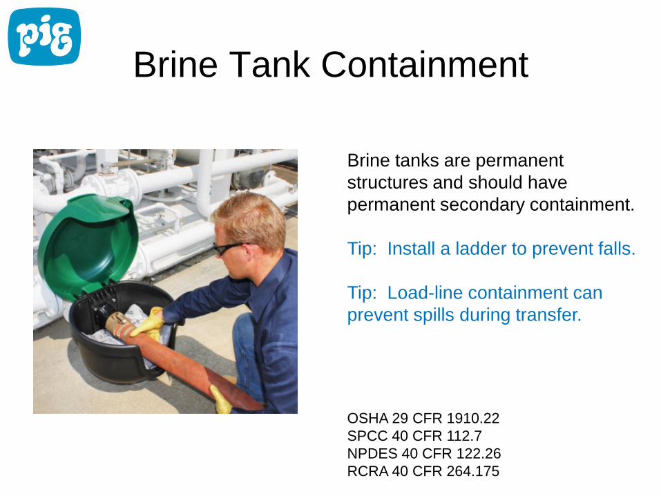
Brine Tank Containment
Brine tanks are permanent structures and should have permanent secondary containment. Tip: Install a ladder to prevent falls. Tip: Load-line containment can prevent spills during transfer.
OSHA 29 CFR 1910.22 SPCC 40 CFR 112.7 NPDES 40 CFR 122.26 RCRA 40 CFR 264.175

Fuel Tank Containment
Fuel tanks should be double wall construction so that secondary containment travels with the tank. Tip: Tertiary containment Tip: Quaternary containment OSHA 29 CFR 1910.22 SPCC 40 CFR 112.7 NPDES 40 CFR 122.26 RCRA 40 CFR 264.175

Equipment Containment
Typically used under generators, light posts, and sewer treaters. Tip: Can be reused from site to site. OSHA 29 CFR 1910.22 SPCC 40 CFR 112.7 NPDES 40 CFR 122.26 RCRA 40 CFR 264.175
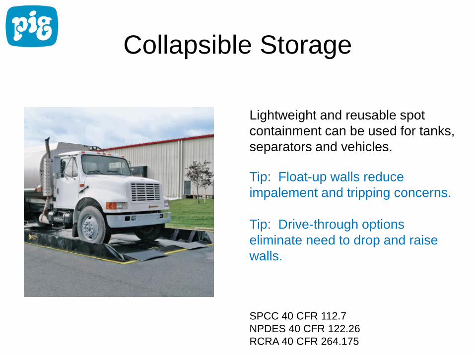
Collapsible Storage
Lightweight and reusable spot containment can be used for tanks, separators and vehicles. Tip: Float-up walls reduce impalement and tripping concerns. Tip: Drive-through options eliminate need to drop and raise walls. SPCC 40 CFR 112.7 NPDES 40 CFR 122.26 RCRA 40 CFR 264.175

Fluid Dispensing
Fluid dispensing is a high-risk area for spills. Tip: Place quick-throw berms under hose connections and valves. OSHA 29 CFR 1910.106 SPCC 40 CFR 112.7 NPDES 40 CFR 122.26

Questions?