second-order sliding mode control of a doubly fed induction - hal
TRANSCRIPT

HAL Id: hal-00705995https://hal.archives-ouvertes.fr/hal-00705995
Submitted on 8 Jun 2012
HAL is a multi-disciplinary open accessarchive for the deposit and dissemination of sci-entific research documents, whether they are pub-lished or not. The documents may come fromteaching and research institutions in France orabroad, or from public or private research centers.
L’archive ouverte pluridisciplinaire HAL, estdestinée au dépôt et à la diffusion de documentsscientifiques de niveau recherche, publiés ou non,émanant des établissements d’enseignement et derecherche français ou étrangers, des laboratoirespublics ou privés.
Second-Order Sliding Mode Control of a Doubly FedInduction Generator Driven Wind Turbine
Brice Beltran, Mohamed Benbouzid, Tarek Ahmed-Ali
To cite this version:Brice Beltran, Mohamed Benbouzid, Tarek Ahmed-Ali. Second-Order Sliding Mode Control of a Dou-bly Fed Induction Generator Driven Wind Turbine. IEEE Transactions on Energy Conversion, Insti-tute of Electrical and Electronics Engineers, 2012, 27 (2), pp.261-269. <10.1109/TEC.2011.2181515>.<hal-00705995>

IEEE TRANSACTIONS ON ENERGY CONVERSION, VOL. 27, NO. 2, JUNE 2012 261
Second-Order Sliding Mode Control of a Doubly FedInduction Generator Driven Wind Turbine
Brice Beltran, Mohamed El Hachemi Benbouzid, Senior Member, IEEE, and Tarek Ahmed-Ali
Abstract—This paper deals with power extraction maximizationof a doubly fed induction generator (DFIG)-based wind turbine.These variable speed systems have several advantages over the tra-ditional wind turbine operating methods, such as the reductionof the mechanical stress and an increase in the energy capture.To fully exploit this latest advantage, many control schemes havebeen developed for maximum power point tracking (MPPT) con-trol schemes. In this context, this paper proposes a second-ordersliding mode to control the wind turbine DFIG according to refer-ences given by an MPPT. Traditionally, the desired DFIG torqueis tracked using control currents. However, the estimations used todefine current references drive some inaccuracies mainly leading tononoptimal power extraction. Therefore, using robust control, suchas the second-order sliding mode, will allow one to directly trackthe DFIG torque leading to maximum power extraction. Moreover,the proposed control strategy presents attractive features such aschattering-free behavior (no extra mechanical stress), finite reach-ing time, and robustness with respect to external disturbances(grid) and unmodeled dynamics (generator and turbine). Simu-lations using the wind turbine simulator FAST and experiments ona 7.5-kW real-time simulator are carried out for the validation ofthe proposed high-order sliding mode control approach.
Index Terms—Control, doubly fed induction generator (DFIG),second-order sliding mode (SOSM), wind turbine (WT).
NOMENCLATURE
WT Wind turbine.DFIG Doubly fed induction generator.SOSM Second-order sliding mode.MPPT Maximum power point tracking.v Wind speed (m/s).ρ Air density (kg/m3).R Rotor radius (m).Pa Aerodynamic power (W).Ta Aerodynamic torque (N·m).λ Tip speed ratio.Cp (λ) Power coefficient.ωmr WT rotor speed (rad/s).ωmg Generator speed (rad/s).
Manuscript received May 26, 2011; revised September 23, 2011 andNovember 18, 2011; accepted December 16, 2011. Date of publication January13, 2012; date of current version May 18, 2012. Paper no. TEC-00255-2011.
B. Beltran and M. E. H. Benbouzid are with the University of Brest,EA 4325 LBMs, 29238 Brest Cedex 03, France (e-mail: [email protected]; [email protected]).
T. Ahmed-Ali is with the University of Caen, UMR CNRS 6072 GREYC,Campus Cote de Nacre, 14032 Caen, Cedex, France (e-mail: [email protected]).
Color versions of one or more of the figures in this paper are available onlineat http://ieeexplore.ieee.org.
Digital Object Identifier 10.1109/TEC.2011.2181515
Tg Generator electromagnetic torque (N·m).Jt Turbine total inertia (kg·m2).Kt Turbine total external damping (N·m/rad·s).d, q Synchronous reference frame index.s, (r) Stator (rotor) index.V (I) Voltage (current).P (Q) Active (reactive) power.φ Flux.Tem Electromagnetic torque.R Resistance.L (M) Inductance (mutual inductance).σ Leakage coefficient, σ = 1 − M2 /LsLr .θr Rotor position.ωr (ωs) Angular speed (Synchronous speed).s Slip.p Pole pair number.
I. INTRODUCTION
ACTUALLY, variable speed WTs are continuously increas-ing their market share, since it is possible to track the
changes in wind speed by adapting shaft speed and, thus, main-taining optimal power generation. The more the variable speedWTs are investigated, the more it becomes obvious that theirbehavior is significantly affected by the control strategy used.Typically, they use aerodynamic controls in combination withpower electronics to regulate torque, speed, and power. Theaerodynamic control systems, usually variable-pitch blades ortrailing-edge devices, are expensive and complex, especiallywhen the turbines are larger [1]. This situation provides a moti-vation to consider alternative control approaches [2].
The main control objective of variable speed WTs is powerextraction maximization. To reach this goal, the turbine tip speedratio should be maintained at its optimum value despite windvariations. Nevertheless, control is not always aimed at cap-turing as much energy as possible. In fact, in previously ratedwind speed, the captured power needs to be limited. Althoughthere are both mechanical and electrical constraints, the moresevere ones are commonly on the generator and the converter.Hence, regulation of the power produced by the generator isusually intended and this is the main objective of this paperfor a DFIG-based WT using an SOSM [3]. Experiments on a7.5-kW real-time simulator are carried out for the validation ofthe proposed high-order sliding mode control approach.
II. WT MODELING [4]
The global scheme for a grid-connected WT is given in Fig. 1.
0885-8969/$31.00 © 2012 IEEE

262 IEEE TRANSACTIONS ON ENERGY CONVERSION, VOL. 27, NO. 2, JUNE 2012
Fig. 1. WT global scheme.
Fig. 2. WT power coefficient.
A. Turbine Model
The turbine modeling is inspired from [4]. In this case, theaerodynamic power Pa captured by the WT is given by
Pa =12πρR2Cp (λ) v3 (1)
where
λ =Rωmr
v. (2)
The Cp–λ characteristics, for different values of the pitch angleβ, are illustrated in Fig. 2. This figure indicates that there is onespecific λ at which the turbine is most efficient. Normally, avariable speed WT follows the Cpmax to capture the maximumpower up to the rated speed by varying the rotor speed to keepthe system at λopt . Then, it operates at the rated power withpower regulation during high wind periods by active control ofthe blade pitch angle or passive regulation based on aerodynamicstall.
The rotor power (aerodynamic power) is also defined by
Pa = ωmrTa . (3)
According to [4], the following simplified model is adoptedfor the turbine (drive train) for control purposes:
Jtωmr = Ta − Ktωmr − Tg . (4)
B. Generator Model
The WT adopted generator is the DFIG (see Fig. 3). DFIG-based WT will offer several advantages including variable speed
Fig. 3. Schematic diagram of a DFIG-based WT.
operation (±33% around the synchronous speed), and four-quadrant active and reactive power capabilities. Such systemalso results in lower converter costs (typically 25% of total sys-tem power) and lower power losses compared to a system basedon a fully fed synchronous generator with full-rated converter.
Moreover, the generator is robust and requires little mainte-nance [5].
The control system is usually defined in the synchronous dqframe fixed to either the stator voltage or the stator flux. For theproposed control strategy, the generator dynamic model writtenin a synchronously rotating frame dq is given by
⎧⎪⎪⎪⎪⎪⎪⎪⎪⎪⎪⎪⎪⎪⎪⎪⎪⎪⎪⎪⎨
⎪⎪⎪⎪⎪⎪⎪⎪⎪⎪⎪⎪⎪⎪⎪⎪⎪⎪⎪⎩
Vsd = RsIsd +dφsd
dt− ωsφsq
Vsq = RsIsq +dφsq
dt+ ωsφsd
Vrd = RrIrd +dφrd
dt− ωrφrq
Vrq = RrIrq + dφr q
dt + ωrφrd
φsd = LsIsd + MIrd
φsq = LsIsq + MIrq
φrd = LrIrd + MIsd
φrq = LrIrq + MIsq
Tem = pM (IrdIsq − Irq Isd) .
(5)
For simplification purposes, the q-axis is aligned with thestator voltage and the stator resistance is neglected [6]. Thesewill lead to⎧⎪⎪⎪⎪⎨
⎪⎪⎪⎪⎩
dIrd
dt=
1σLr
(
Vrd − RrIrd + sωsσLrIrq −M
Ls
dφsd
dt
)
dIrq
dt=
1σLr
(
Vrq − RrIrq − sωsσLrIrd − sωsM
Lsφsd
)
Tem = −p MLs
φsdIrq .(6)
III. CONTROL OF THE DFIG-BASED WT
A. Problem Formulation
WTs are designed to produce electrical energy as cheaplyas possible. Therefore, they are generally designed so that theyyield maximum output at wind speeds around 15 m/s. In case

BELTRAN et al.: SECOND-ORDER SLIDING MODE CONTROL OF A DOUBLY FED INDUCTION GENERATOR DRIVEN WIND TURBINE 263
Fig. 4. WT control regions.
of stronger winds, it is necessary to waste part of the excessenergy of the wind in order to avoid damaging the WT. All WTsare, therefore, designed with some sort of power control. Thisstandard control law keeps the turbine operating at the peak ofits Cp curve
Tref = kω2 , with k =12πρR5 Cp max
λ3opt
. (7)
There is a significant problem with this standard control. In-deed, wind speed fluctuations force the turbine to operate offthe peak of its Cp curve much of the time. Tight tracking Cpmaxwould lead to high mechanical stress and transfer aerodynamicfluctuations in to the power system. This, however, will resultin less energy capture.
To effectively extract wind power while at the same timemaintaining safe operation, the WT should be driven accordingto the following three fundamental operating regions associatedwith wind speed, maximum allowable rotor speed, and ratedpower. The three distinct regions are shown in Fig. 4, wherevr max is the wind speed at which the maximum allowable ro-tor speed is reached, while vcutoff is the furling wind speedat which the turbine needs to be shut down for protection. Inpractice, there are three possible regions of turbine operation,namely the high-, constant-, and low-speed regions. High-speedoperation (III) is frequently bounded by the power limit of themachine while speed constraints apply in the constant-speedregion. Conversely, regulation in the low-speed region (I) isusually not restricted by speed constraints. However, the sys-tem has nonlinear nonminimum phase dynamics in this region.This adverse behavior is an obstacle to perform the regulationtask [7].
A common practice in addressing DFIG control problem isto use a linearization approach [8]–[10]. However, due to thestochastic operating conditions and the inevitable uncertaintiesinherent in DFIG-based WTs, much of these control methodscome at the price of poor system performance and low reliabil-ity. Hence, the need for nonlinear and robust control to take intoaccount these control problems. Although many modern tech-
niques can be used for this purpose [11], sliding mode controlhas proved to be especially appropriate for nonlinear systems,presenting robust features with respect to system parameter un-certainties and external disturbances. For WT control, slidingmode should provide a suitable compromise between conver-sion efficiency and torque oscillation smoothing [4], [12], [13].
Sliding mode control copes with system uncertainty keepinga properly chosen constraint by means of high-frequency controlswitching. Featuring robustness and high accuracy, the standard(first-order) sliding mode usage is, however, restricted due tothe chattering effect caused by the control switching, and theequality of the constraint relative degree to 1.
High-order sliding mode approach suggests treating the chat-tering effect using a time derivative of control as a new control,thus integrating the switching [14]–[16].
B. SOSMs Control Design
As the chattering phenomenon is the major drawback of prac-tical implementation of sliding mode control, the most efficientways to cope with this problem is higher order sliding mode.This technique generalizes the basic sliding mode idea by act-ing on the higher order time derivatives of the sliding manifold,instead of influencing the first time derivative as it is the casein the standard (first order) sliding mode. This operational fea-ture allows mitigating the chattering effect, keeping the mainproperties of the original approach [17].
The DFIG stator-side reactive power is given by
Qs =32
(Vsq Isd − VsdIsq ) . (8)
For a decoupled control, a dq reference frame attached to thestator flux was used. Therefore, setting the stator flux vectoraligned with the d-axis, the reactive power can be expressed as
Qs =32
Vs
Ls(φs − MIrd) . (9)
Setting the reactive power to zero will, therefore, lead to therotor reference current
Ird ref =Vs
ωsM. (10)
The DFIG-based WT control objective is to optimize the windenergy capture by tracking the optimal torque Tref (7). Thiscontrol objective can be formulated by the following trackingerrors:
{eIr d
= Ird − Ird refeTe m = Tem − Tref .
(11)
Then, we will have⎧⎪⎪⎪⎪⎪⎪⎪⎪⎪⎨
⎪⎪⎪⎪⎪⎪⎪⎪⎪⎩
eIr d=
1σLr
×(
Vrd − RrIrd + sωsLrσIrq −M
Ls
dφsd
dt
)
− Ird ref
eTe m = −pM
σLsLrφs
×(
Vrq − RrIrq − sωsLrσIrd − sωsM
Lsφsd
)
− Tref .
(12)

264 IEEE TRANSACTIONS ON ENERGY CONVERSION, VOL. 27, NO. 2, JUNE 2012
If we define the functions G1 and G2 as follows:
⎧⎪⎪⎪⎪⎨
⎪⎪⎪⎪⎩
G1 =1
σLr
(
sωsσLrIrq −M
Ls
dφsd
dt− RrIrd
)
− Ird ref
G2 = −pM
σLsLrφs
×(−RrIrq − sωsσLrIrd − sωs
MLs
φsd
)− Tref
(13)then we have
⎧⎪⎨
⎪⎩
eIr d=
1σLr
Vrd + G1
eΓe m = −pM
σLsLrφsVrq + G2 .
(14)
To overcome standard sliding mode control chattering, a natu-ral modification is to replace the discontinuous function in thevicinity of the discontinuity by a smooth approximation. Nev-ertheless, such a smooth approximation is not easy to carry out.This is why common approaches use current references. There-fore, a high-order sliding mode seems to be a good alternative.
The main problem with high-order sliding mode algorithmimplementations is the increased required information. Indeed,the implementation of an nth-order controller requires theknowledge of S, S, . . ., S(n−1) . The exception is the supertwist-ing algorithm, which only needs information about the slidingsurface S [17]. Therefore, the proposed control approach hasbeen designed using this algorithm.
Now, let us consider the following SOSM controller basedon the supertwisting algorithm [17]. In the considered case,the control could be approached by two independent SOSMcontrollers. Indeed, the control matrix is approximated by adiagonal one. Hence, Vrd controls Ird (reactive power) and Vrq
controls the torque MPPT strategy
{Vrd = y1 − B1 |eIr d
|1/2 sgn (eIr d) , y1 = −B2sgn (eIr d
)Vrq = y2 + B3 |eTe m |
1/2 sgn (eTe m ) , y2 = +B4sgn (eTe m)(15)
where the constants B1 , B2 , B3 , and B4 are defined as⎧⎪⎪⎪⎨
⎪⎪⎪⎩
B21 > 2σ 2 L2
r ((B2 /σLr )+Φ1 )((B2 /σLr )−Φ1 ) , B2 > σLrΦ1 ,
∣∣∣G1
∣∣∣ < Φ1
B23 > 2
(σLs Lr
pM
)2 (p(M/σLs Lr )B4 +Φ2 )(p(M/σLs Lr )B4 −Φ2 ) , B4 > σLs Lr
pM Φ2∣∣∣G2
∣∣∣ < Φ2 .
(16)Proof: Let us consider the case of Vrd . In this case, we have
eIr d=
1σLr
(
−B2sgn(eIr d) − B1
12
eIr d
|eIr d|1/2
)
+ G1 (17)
and, therefore, the supertwisting algorithm phase trajectory isillustrated in Fig. 5.
Assume now, for simplicity, that the initial values are eIr d= 0
and eIr d= e0 > 0 at t = 0. Let eM be the intersection of the
curve eIr d= − (B2/σLr − Φ1) with eIr d
= 0. We have then
2eM
(B2
σLr− Φ1
)
= e20 (18)
Fig. 5. Supertwisting algorithm phase trajectory.
Fig. 6. Proposed control structure.
eIr d> 0, eIr d
< − 2B1
(σLrΦ1 + B2) e2Ir d
⇒ eIr d> 0.
Thus, the majorant curve with eIr d> 0 may be taken as
⎧⎪⎪⎪⎪⎨
⎪⎪⎪⎪⎩
e2Ir d
= 2(
B2σLr
− Φ1
)(eM − eIr d
) with eIr d> 0
eIr d= eM with 0 ≥ eIr d
≥ − 2B1
(σLrΦ1 + B2) e1/2Ir d
eIr d= eM = − 2
B1(σLrΦ1 + B2) e
1/2M
with eIr d> − 2
B1(σLrΦ1 + B2) e
1/2Ir d
.
Let the trajectory next intersection with eIr d= 0 axis be e1 .
Then, it follows that∣∣∣∣e1
e0
∣∣∣∣ ≤ q with q =
∣∣∣∣eM
e0
∣∣∣∣ =
√2 ((B2/σLr ) + Φ1)
(B1/σLr )2 ((B2/σLr ) − Φ1)
.
(19)Extending the trajectory into the half plane eIr d
< 0 and car-rying out a similar reasoning show that successive crossings ofthe eIr d
= 0 axis satisfy the inequality∣∣∣∣ei+1
ei
∣∣∣∣ ≤ q.
BELTRAN et al.: SECOND-ORDER SLIDING MODE CONTROL OF A DOUBLY FED INDUCTION GENERATOR DRIVEN WIND TURBINE 265
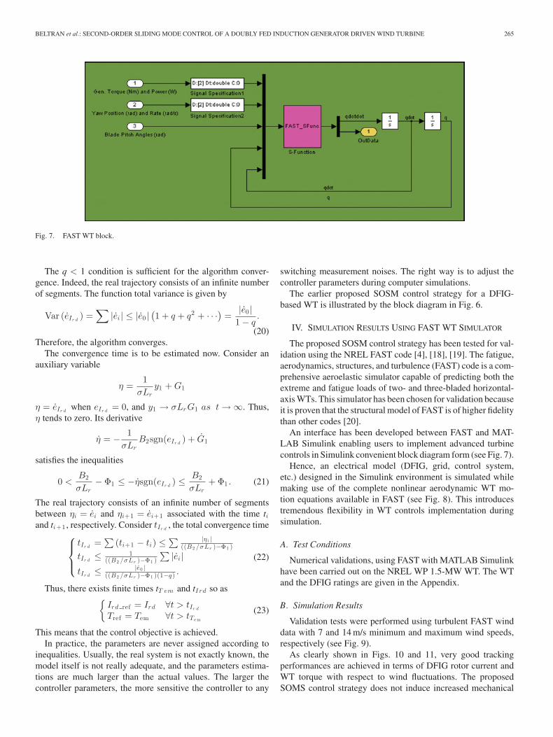
Fig. 7. FAST WT block.
The q < 1 condition is sufficient for the algorithm conver-gence. Indeed, the real trajectory consists of an infinite numberof segments. The function total variance is given by
Var (eIr d) =
∑|ei | ≤ |e0 |
(1 + q + q2 + · · ·
)=
|e0 |1 − q
.
(20)Therefore, the algorithm converges.
The convergence time is to be estimated now. Consider anauxiliary variable
η =1
σLry1 + G1
η = eIr dwhen eIr d
= 0, and y1 → σLrG1 as t → ∞. Thus,η tends to zero. Its derivative
η = − 1σLr
B2sgn(eIr d) + G1
satisfies the inequalities
0 <B2
σLr− Φ1 ≤ −ηsgn(eIr d
) ≤ B2
σLr+ Φ1 . (21)
The real trajectory consists of an infinite number of segmentsbetween ηi = ei and ηi+1 = ei+1 associated with the time tiand ti+1 , respectively. Consider tIr d
, the total convergence time⎧⎪⎨
⎪⎩
tIr d=
∑(ti+1 − ti) ≤
∑ |ηi |((B2 /σLr )−Φ1 )
tIr d≤ 1
((B2 /σLr )−Φ1 )
∑|ei |
tIr d≤ |e0 |
((B2 /σLr )−Φ1 )(1−q) .
(22)
Thus, there exists finite times tT em and tI rd so as{
Ird ref = Ird ∀t > tIr d
Tref = Tem ∀t > tTe m
(23)
This means that the control objective is achieved.In practice, the parameters are never assigned according to
inequalities. Usually, the real system is not exactly known, themodel itself is not really adequate, and the parameters estima-tions are much larger than the actual values. The larger thecontroller parameters, the more sensitive the controller to any
switching measurement noises. The right way is to adjust thecontroller parameters during computer simulations.
The earlier proposed SOSM control strategy for a DFIG-based WT is illustrated by the block diagram in Fig. 6.
IV. SIMULATION RESULTS USING FAST WT SIMULATOR
The proposed SOSM control strategy has been tested for val-idation using the NREL FAST code [4], [18], [19]. The fatigue,aerodynamics, structures, and turbulence (FAST) code is a com-prehensive aeroelastic simulator capable of predicting both theextreme and fatigue loads of two- and three-bladed horizontal-axis WTs. This simulator has been chosen for validation becauseit is proven that the structural model of FAST is of higher fidelitythan other codes [20].
An interface has been developed between FAST and MAT-LAB Simulink enabling users to implement advanced turbinecontrols in Simulink convenient block diagram form (see Fig. 7).
Hence, an electrical model (DFIG, grid, control system,etc.) designed in the Simulink environment is simulated whilemaking use of the complete nonlinear aerodynamic WT mo-tion equations available in FAST (see Fig. 8). This introducestremendous flexibility in WT controls implementation duringsimulation.
A. Test Conditions
Numerical validations, using FAST with MATLAB Simulinkhave been carried out on the NREL WP 1.5-MW WT. The WTand the DFIG ratings are given in the Appendix.
B. Simulation Results
Validation tests were performed using turbulent FAST winddata with 7 and 14 m/s minimum and maximum wind speeds,respectively (see Fig. 9).
As clearly shown in Figs. 10 and 11, very good trackingperformances are achieved in terms of DFIG rotor current andWT torque with respect to wind fluctuations. The proposedSOMS control strategy does not induce increased mechanical

266 IEEE TRANSACTIONS ON ENERGY CONVERSION, VOL. 27, NO. 2, JUNE 2012
Fig. 8. Simulink model.
Fig. 9. Wind speed profile.
Fig. 10. Current Ir d tracking performance: reference (blue) and real (green).
stress as there are no strong torque variations. Indeed and asexpected, the aerodynamic torque remains smooth (see Fig. 11).
To assess the effectiveness of the proposed advanced controlstrategy, it has been compared to more traditional techniqueswith the same control objectives. The first one is that using theactive power as reference [21]
Pref = Trefω = kω3 ⇒ Irq ref = − Ls
VsMPref . (24)
This approach supposes that the active power is equal to theDFIG electromagnetic power. This approximation drives a dif-
Fig. 11. Torque tracking performance: reference (blue) and real (green).
Fig. 12. Torque: reference (blue) and real (green) [21].
Fig. 13. Torque: reference (blue) and real (green) [22].
ference between the desired torque given by (7) and the gener-ated torque (see Fig. 12).
The second assessed approach is the one using the followingreference [22]:
Irq ref = − Ls
pMφsTref . (25)
In this case, bad tracking performances are also achieved (seeFig. 13). Indeed, the control reference is quite inaccurate due tosome adopted simplifications (e.g., a constant stator flux).
In terms of power extraction and maximization, Fig. 14 showsthe effectiveness of the proposed SOSM control with respect to(25) approach. This is mainly due to an inaccurate determinationof kopt (7). Indeed, there is no accurate way to determine k, es-pecially since blade aerodynamics can change significantly overtime. This fact is, therefore, an extra justification of the proposedcontrol strategy. If it is assumed that k can be accurately deter-mined via simulations or experiments, Fig. 15 shows that (24)and (25) approaches bad torque tracking can be balanced by theadjustment of kopt . This delicate task, which requires a numberof simulation tests, remains less efficient as it is illustrated inFig. 16.

BELTRAN et al.: SECOND-ORDER SLIDING MODE CONTROL OF A DOUBLY FED INDUCTION GENERATOR DRIVEN WIND TURBINE 267
Fig. 14. Generated power: SOSM (blue) and (25) approach (green).
Fig. 15. Generated power: HOSM (blue), (24), and (25) approaches (greenand red) with kopt adjustment.
Fig. 16. Generated energy: HOSM (blue), (24), and (25) approaches (greenand red) with kopt adjustment.
V. EXPERIMENTAL RESULTS
A. Test Bench
The test bench presented in Fig. 17 allows the physical sim-ulation of the WT power system. The WT is emulated by a dcmotor, which reproduces the torque and the inertia with respectto wind speeds and turbine rotational speed. The dc motor iscoupled to a 7.5-kW DFIG (see the Appendix) [14].
B. Experimental Tests
Figs. 18 and 19 show experimental control performances ofthe emulated DFIG-based WT. These results show very goodtracking performances in terms of the DFIG torque and rotorcurrent. Indeed, Fig. 18 illustrates good tracking of the desiredtorque given by the MPPT. This is an indication that the WTpower capture is optimized.
Fig. 17. Components of the G2Elab test bench, Grenoble, France:©1 dc motor,©2 DFIG, ©3 Power electronics for driving the dc motor, ©4 Power electronicsfor driving the DFIG, ©5 DSP TMS320F240 implementing dc motor control, ©6DSP DS1005 (dSPACE) implementing PMSG-based MCT control.
Fig. 18. Torque: reference (red) and real (blue).
Fig. 19. Ir d : reference (red) and real (blue).
Fig. 20. Torque: reference (red) and real (blue).

268 IEEE TRANSACTIONS ON ENERGY CONVERSION, VOL. 27, NO. 2, JUNE 2012
Fig. 21. Ir d : reference (red) and real (blue).
Fig. 22. DFIG generated power.
For comparison purposes, a classical PI control, using currentreferences, has been tested. Figs. 20 and 21 show the achievedperformances. In this case, poor torque tracking performancesare achieved (see Fig. 20).
In the case of Ird tracking, which allows the reactive powerminimization, one can observe chattering with SOSM control(see Fig. 19). This is mainly due to measurements as it is con-firmed by PI control (see Fig. 21). It should be mentioned thatthis phenomenon is largely amplified by Park transform.
For illustration, Fig. 22 shows the generated power.
VI. CONCLUSION
This paper dealt with an SOSM control of doubly fedinduction-based WT. Its main features are a chattering-free be-havior, a finite reaching time, and robustness with respect toexternal disturbances (grid) and unmodeled dynamics (DFIGand WT). The proposed SOSM control the WT DFIG accord-ing to references given by an MPPT. In this case, the DFIGtorque is directly tracked, therefore leading to maximum powerextraction.
The proposed control strategy has been tested using the NRELFAST simulator on a 1.5-MW three-blade DFIG-based WT.Moreover, experiments on a 7.5-kW real-time simulator havebeen carried out. The obtained results clearly show the SOSMapproach effectiveness in terms of power extraction maximiza-tion compared to more traditional techniques. Moreover, it hasbeen confirmed that there is no mechanical extra stress inducedon the WT drive train as there are no strong torque variations.
APPENDIX
CHARACTERISTICS OF THE SIMULATED WT:
ACKNOWLEDGMENT
The authors would like to thank Prof. S. Bacha from theGrenoble Electrical Engineering Laboratory, Grenoble, France,for allowing the use of the renewable energy experimentalfacilities.
REFERENCES
[1] M. Liserre, R. Cardenas, M. Molinas, and J. Rodriguez, “Overview ofmulti-MW wind turbines and wind parks,” IEEE Trans. Ind. Electron.,vol. 58, no. 4, pp. 1081–1095, Apr. 2011.
[2] F. D. Bianchi, H. de Battista, and R. J. Mantz, Wind Turbine ControlSystems. Principles, Modelling and Gain Scheduling Design. London,U.K.: Springer, 2007.
[3] B. Beltran, M. E. H. Benbouzid, and T. Ahmed-Ali, “High-order slidingmode control of a DFIG-based wind turbine for power maximization andgrid fault tolerance,” in Proc. IEEE Int. Elect. Mach. Drives Conf., Miami,FL, May 2009, pp. 183–189.
[4] B. Beltran, T. Ahmed-Ali, and M. E. H. Benbouzid, “Sliding mode powercontrol of variable speed wind energy conversion systems,” IEEE Trans.Energy Convers., vol. 23, no. 22, pp. 551–558, Jun. 2008.
[5] M. Tazil, V. Kumar, R. C. Bansal, S. Kong, Z. Y. Dong, W. Freitas, and H.D. Mathur, “Three-phase doubly fed induction generators: An overview,”IET Elect. Power Appl., vol. 4, no. 2, pp. 75–89, Feb. 2010.
[6] C. H. Liu and Y. Y. Hsu, “Effect of rotor excitation voltage on steady-statestability and maximum output power of a doubly fed induction generator,”IEEE Trans. Ind. Electron., vol. 58, no. 4, pp. 1096–1109, Apr. 2011.
[7] T. Senjyu, R. Sakamoto, N. Urasaki, T. Funabashi, H. Fujita, and H. Sekine,“Output power leveling of wind turbine generator for all operating regionsby pitch angle control,” IEEE Trans. Energy Convers., vol. 21, no. 2,pp. 467–475, Jun. 2006.
BELTRAN et al.: SECOND-ORDER SLIDING MODE CONTROL OF A DOUBLY FED INDUCTION GENERATOR DRIVEN WIND TURBINE 269
[8] R. Pena, R. Cardenas, J. Proboste, G. Asher, and J. Clare, “Sensorlesscontrol of doubly-fed induction generators using a rotor-current-basedMRAS observer,” IEEE Trans. Ind. Electron., vol. 55, no. 1, pp. 330–339, Jan. 2008.
[9] L. Xu and P. Cartwright, “Direct active and reactive power control of DFIGfor wind energy generation,” IEEE Trans. Energy Convers., vol. 21, no. 3,pp. 750–758, Sep. 2006.
[10] R. Cardenas, R. Pena, J. Proboste, G. Asher, and J. Clare, “MRAS observerfor sensorless control of standalone doubly fed induction generators,”IEEE Trans. Energy Convers., vol. 20, no. 4, pp. 710–718, Dec. 2005.
[11] R. Vepa, “Nonlinear, optimal control of a wind turbine generator,” IEEETrans. Energy Convers., vol. 26, no. 2, pp. 468–478, Jun. 2011.
[12] I. MunteanuS. Bacha, A. I. Bratcu, J. Guiraud, and D. Roye, “Energy-reliability optimization of wind energy conversion systems by slidingmode control,” IEEE Trans. Energy Convers., vol. 23, no. 3, pp. 975–985, Sep. 2008.
[13] F. Valenciaga and P. F. Puleston, “Variable structure control of a windenergy conversion system based on a brushless doubly fed reluctancegenerator,” IEEE Trans. Energy Convers., vol. 22, no. 2, pp. 499–506,Jun. 2008.
[14] S. Benelghali, M. E. H. Benbouzid, J. F. Charpentier, T. Ahmed-Ali, andI. Munteanu, “Experimental validation of a marine current turbine sim-ulator: Application to a PMSG-based system second-order sliding modecontrol,” IEEE Trans. Ind. Electron., vol. 58, no. 1, pp. 118–126, Jan.2011.
[15] B. Beltran, T. Ahmed-Ali, and M. E. H. Benbouzid, “High-order slidingmode control of variable speed wind turbines,” IEEE Trans. Ind. Electron.,vol. 56, no. 9, pp. 3314–3321, Sep. 2009.
[16] F. Valenciaga and P. F. Puleston, “High-order sliding control for a windenergy conversion system based on a permanent magnet synchronousgenerator,” IEEE Trans. Energy Convers., vol. 23, no. 3, pp. 860–867,Sep. 2008.
[17] A. Levant and L. Alelishvili, “Integral high-order sliding modes,” IEEETrans. Autom. Control, vol. 52, no. 7, pp. 1278–1282, Jul. 2007.
[18] (2011). [Online]. Available: http://wind.nrel.gov/designcodes/simulators/fast/.[19] R. Fadaeinedjad, M. Moallem, and G. Moschopoulos, “Simulation of a
wind turbine with doubly fed induction generator by FAST and Simulink,”IEEE Trans. Energy Convers., vol. 23, no. 2, pp. 690–700, Jun. 2008.
[20] A. Manjock “Design codes FAST and ADAMS R© for load calculationsof onshore wind turbines,” Germanischer Lloyd WindEnergie GmbH,Hamburg, Germany, Rep. 72042, May 26, 2005.
[21] F. Poitiers, T. Bouaouiche, and M. Machmoum, “Advanced control of adoubly-fed induction generator for wind energy conversion,” Elect. PowerSyst. Res., vol. 79, no. 7, pp. 1085–1096, Jul. 2009.
[22] R. Cardenas and R. Pena, “Sensorless vector control of induction ma-chines for variable-speed wind energy applications,” IEEE Trans. EnergyConvers., vol. 19, no. 1, pp. 196–205, Mar. 2004.
Brice Beltran was born in Arles, France, in 1981. Hereceived the Engineer Degree in electrical engineer-ing from the Ecole Nationale Superieure d’Ingenieursdes Etudes et Techniques d’Armement, Brest, France,and the Ph.D. degree in electrical engineering fromthe University of Brest, Brest, in 2006 and 2010,respectively.
In 2006, he joined the Delegation Generale pourl’Armenent as an Engineer and Technical Expert ininformation systems. In January 2010, he joined theBrest Laboratory of Mechanics and Systems, Univer-
sity of Brest, as an Associate Member. His current research interests includemodeling and control of renewable energy applications.
Mohamed El Hachemi Benbouzid (S’92–M’95–SM’98) was born in Batna, Algeria, in 1968. He re-ceived the B.Sc. degree in electrical engineering fromthe University of Batna, Batna, in 1990, the M.Sc. andPh.D. degrees in electrical and computer engineeringfrom the National Polytechnic Institute of Grenoble,Grenoble, France, in 1991 and 1994, respectively,and the Habilitation a Diriger des Recherches de-gree from the University of Picardie “Jules Verne,”Amiens, France, in 2000.
After receiving the Ph.D. degree, he joined theProfessional Institute of Amiens, University of Picardie “Jules Verne,” wherehe was an Associate Professor of electrical and computer engineering. SinceSeptember 2004, he has been with the Institut Universitaire de Technologie ofBrest, University of Brest, Brest, France, where he is a Professor of electrical en-gineering. His main research interests and experience include analysis, design,and control of electric machines, variable-speed drives for traction, propulsion,and renewable energy applications, and fault diagnosis of electric machines.
Dr. Benbouzid is a senior member of the IEEE Power Engineering, In-dustrial Electronics, Industry Applications, Power Electronics, and VehicularTechnology Societies. He is an Associate Editor of the IEEE TRANSACTIONS ON
ENERGY CONVERSION, the IEEE TRANSACTIONS ON INDUSTRIAL ELECTRONICS,the IEEE TRANSACTIONS ON VEHICULAR TECHNOLOGY, and the IEEE/ASMETRANSACTIONS ON MECHATRONICS.
Tarek Ahmed-Ali was born in Algiers, Algeria, in1972. He received the B.Sc. degree in electrical en-gineering from the Ecole Nationale Polytechnique ofAlgiers, Algiers, in 1994, the M.Sc. degree in elec-trical and computer engineering from the Universityof Paris VI, Paris, France, in 1995, and the Ph.D. de-gree in electrical and computer engineering from theUniversity of Paris Sud, Paris, in 1998.
In 1998, he joined the University of Paris XIII,Paris, as a Teaching and Research Assistant. In 1998,he was also with the Ecole Centrale de Lille, Lille,
France, as a Teaching and Research Assistant. In 2000, he joined Societe Na-tionale des Chemins de fer francais (the French National Railway Corporation)as a Research and Development Engineer. In 2002, he became a Lecturer incontrol engineering at Ecole Nationale des Ingenieurs des Etudes et Techniquesde l’Armement, Brest, France. In 2008, he joined as an Associate Professor atthe University of Caen, Caen, France, where he became a Professor of auto-matic control in 2010. His main research interests include sliding mode control,nonlinear observers, and fault-tolerant control and diagnosis in the field of acdrives.