secial report march 19w0, llvllz l · march 19w0, llvllz l ... the contents of this report are not...
TRANSCRIPT

Secial Report 80-11March 19W0, LLVLLz LAD AL97
17 SNOW FORTIFICATIONS AS PROTECTION
AGAINST SHAPED CHARGE ANTITANK' I PROJECTILES
, DTIC,;' I[! ~ELECTE . ,
Dennis Farrell
- amd Ia,RECTORATE OF MILITARY PROGRAMSOFFICE, CHIEF OF ENGINEERS
UNITED STATES ARMYCORPS OF ENGINEERSCOLD REGIONS RESEARCH AND ENGINEERING LABORATORYHANOVER, NEW HAMPSHIRE, U.S.A.
for publ relu"a dtu- m819 245

Unclassified
SECURITY CLASSIFICATIO)N Of THIS AE(Wheun Does Entered)
REPORT DOCUMENTATION PAGE BFRE COSTRUTINS O
.010M F 2. GOVT ACCESSION NO. 3. RECIPIENT'S CATALOG NUMBER
S . TYPE OF REPORT & PERIOD COVERED]
SNOW FORTIFICATIONS AS PROTFCTION AGAINST~HPD 6 EFRIGOG EOTNME
7. AUTHOR(q) G. CONTRACT OR GRANT NUMBER(q)
10 Denni Farrell6
U.S. Army Cold Regions Research and Engineering DA Proet 4723A4LaboratoryTakA t0
Hanover, New Hampshire 0375511. CONTROLLING OFFICE NANE AND ADDRESS
14. MONITORING AGENCY NAME & ADORESS(i different from Controlling Offic*) IS. SECURITY CLASS. (of thi. report)
UnclassifiedIr.DECLASSI FICATION/ DOWN4GRADING
L7HEULE1S. DISTRIBUTION STATEMENT (of lte Report)
Approved for public release; distribution unlimited.
17. DISTRIBUTION STATEMENT (of the obstract entered In Block 2", If different frow Report)
IG. SUPPLEE*9fy PES ( L ~~ ~ ~L
19. KEY WORDS (Continue on reverse side it necessary end Identify by block number)
Construction materials
This report chronicles an investigation of the effectiveness of snowfotfctos
The test was planned to observe and measure how packed snow adsorbs theenergy of high explosive antitank (HEAT) ammunition. In the test plan weconsidered both the possibility of non-detonation due to insufficient resis-tance in snow and the rate of deterioration of a snow embankment with repeatedimpacts. The 90-mm M467 recoilless rifle was used because it has a relatively
DD 10ON"" 3 rDTolUo"o 11 SNov 69 is OOLETE Unclassified
SZCumI~r CLASSIFICATION OF THIS PAGE (eM Votet. ate

UnclassifiedSECURITY CLASSIFICATION OF THIS PAG09(hae Dae RntMQ
20. Abstract (cont.)
low velocity and its charge was more likely to not detonate than that of a highvelocity weapon. The charge weight and configuration were similar to otherammunition of this caliber. We found tha,(l) 29 of 30 live rounds detonatedon impact' Q) damage to inert rounds which Avere retrieved from the embankmentranged from slight to hegligible,(3) maximum penetration of the shaped chargewas less than 3.5 m; maximum penetration of the inert rounds was less than3.0 m: and&) a packed snow embankment does not deteriorate rapidly undersustained fire. These findings indicate that snow can be used to good advan-tage for building expedient fortifications, particularly in situations wherelarge volumes of snow have to be cleared from roads and airfields.
Ao@@S3zi For
~ ?"A
L.[
1r Unclassifie
SCUITYCLASIFIATIO"OFTISPA,(Wh. _a..__...
PREFACE
This report was prepared by Dennis R. Farrell, Mechanical Engineer,Civil Engineering Research Branch, Experimental Engineering Division,U.S. Army Cold Regions Research and Engineering Laboratory.
The study was funded under DA Project 4A762730AT42, Design, Con-struction and Operations Technology for Cold Regions; Task Al, Ice andSnow Technology; Work Unit 001, Terminal Ballistics in Snow, Ice andFrozen Soil.
The author expresses appreciation to Mr. George Aitken and Dr.George Swinzow for their comments on the test procedures and review ofthis report and to LTC Getman for giving us the opportunity to observethe operations of the air-to-ground practice ranges at Ft. Drum, N.Y.
The contents of this report are not to be used for advertising orpromotional purposes. Citation of brand names does not constitute anofficial endorsement or approval of the use of such commercial products.
tit

Contents
Page
Abstract................. . . ... ... .. .. .. .. .........Preface.................. . . ... ... .. .. .. . . ........Introduction.................. . . ... . ... .. .. .. .. .... 171 Target construction.............. . . .... .. .. .. .. .....Test equipment and procedure. .. ....... .......... 2Test results. .. ........... .............. 2Conclusions .. .......... ................ 6:1Recommendations .. .......... .............. 9Appendix .. .. ........ .................. 10
ILLUSTRATIONS
Figure
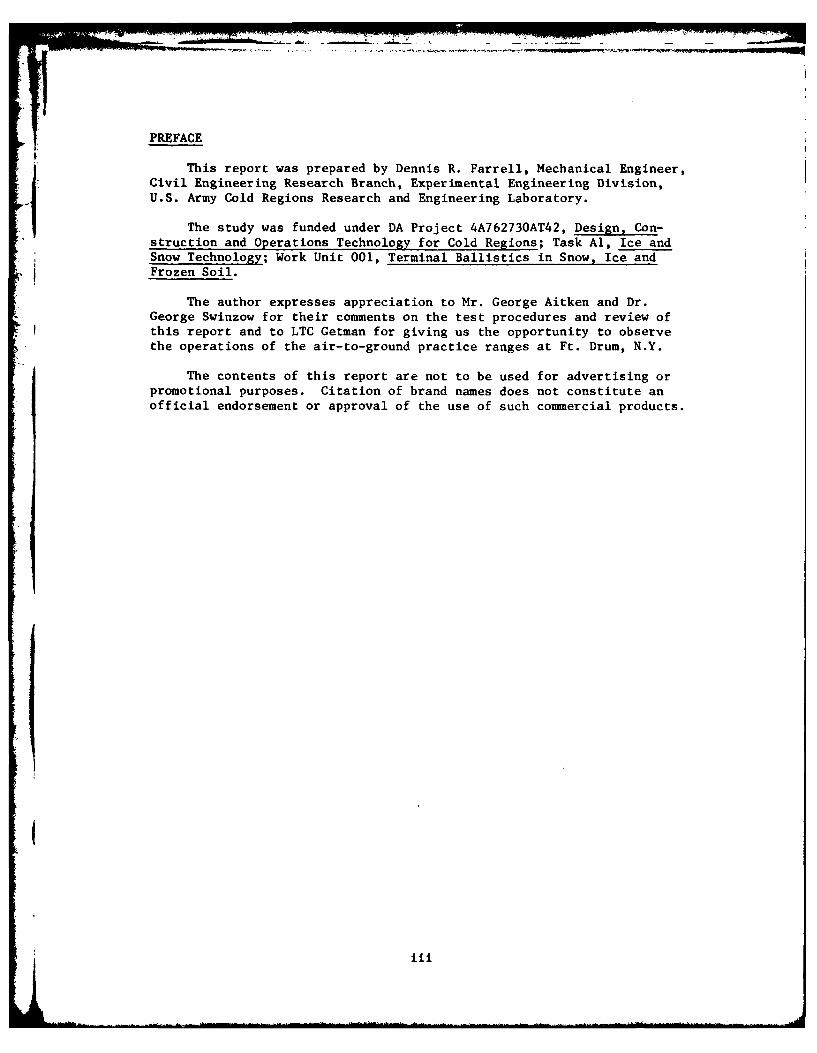
1. M67 recoilless rifle and M371EI HEAT (high explosiveantitank) ammunition. .. .......... ...... 3
2. Loading the recoilless rifle. .. ............ 3
3. Excavating the snow berm with a D-6 tractor . ... 4
4. Shaped charge jet trajectory exposed by excavation. 4
5. Excavated inert round trajectory .. .. ......... 7
6. An inert round that penetrated the berm. .. ...... 7
7. Nose caps of three 90-mm inert rounds recovered fromsnow berm .. ........ .............. 8
8. 90-rn HEAT cartridge M371E1. .. ............ 8
TABLES
Table
1. Comparison of hand- and machine-built snow em-bankments .. ......... . ............ 2
2. Measurements of shaped charge and inert roundpenetration .. ......... ............ 5
3. Dimensions of trenches excavated by 90-rn inert
rounds impacting at low angles and broaching. . . . 9
iv

INTRODUCTION
The work described in this report was conducted as part of aninvestigation by the U.S. Army Cold Regions Research and EngineeringLaboratory into the terminal ballistics of various projectiles in snow,ice and frozen soil. The report describes the results of tests con-ducted at Ft. Drum, N.Y., in which HEAT (high explosive antitank) and
inert rounds were fired from a 90-mm recoilless rifle (Fig. 1, 2) at~snow embankments.
i "A review of Army publications on northern operations indicated that
rapid construction of defensive positions in a winter environment requiresspecial techniques. Several of the Army Field Manuals provide informa-
tion about construction of defensive positions using materials otherthan soil when the frost layer is too thick for rapid manual excavation.At least four of the manuals have tables that give the quantity of snowrequired to stop bullets from small arms. These manuals are:
1) FM 5-15, Field Fortifications2) FM 31-70, Basic Cold Weather Manual3) FM 31-71, Northern Operations
4) TM 5-349, Arctic Construction
The work described in this report was conducted to determine ifsnow in reasonable quantities could also be used to protect stationaryvehicles, parked aircraft, and fixed facilities against the largerarmor-piercing infantry weapons. The objectives of the tests wereI) to determine the problems associated with collecting large volumes ofsnow under field conditions, 2) to observe the functioning of a typicalpiezoelectric fuze when it strikes packed snow, and 3) to measure theability of snow to absorb the focused explosive force of a shaped-chargeantitank round.
TARGET CONSTRUCTION
A 6-m-thick, 2 1/2-m-high 40-m-long snow embankment was constructedusing a D-6 tractor and a 2-ydl capacity front end loader. Because thetwo vehicles worked in tandem collecting and piling the snow, productionrates are not available for each piece of equipment separately. Theoverall production rate was 48 m 3/hr.
Johnson (1977)* reported that two men with large scoops produceda 14-m 3 snowpile from undisturbed snow at the rate of 11.2 m3 /hr. Thisrate compares favorably with that of the heavy equipment (see Table 1),but natural conditions and test requirements (particularly the require-ment for minimal contamination by soil) reduced the production rate ofthe heavy equipment by at least a factor of two. It is suggested thatthe figure of 48 m3 /hr for the two machines should be viewed as thelower limit for the production rate of this type of equipment under
these conditions.
*Johnson, P. (1977) Defensive Works of Subarctic Snow. CRREL Report
77-6, April.

Table 1. Comparison of hand- ond machine-built snow embankments.
Type of Density Initial Embankment Rate ofconstruction Initial Final snow depth volume const.
(Mg/m ) (cm) (m ) (m3 /hr)
Hand 0.18 0.34 66 14.0 11.2Machine 0.24 0.44 47 600 48
TEST EQUIPMENT AND PROCEDURE
Aberdeen Proving Ground, Maryland, provided 30 rounds of 90-mmHEAT M371E ammunition, 20 inert rounds, and an M67 90-mm recoillessrifle (Fig. 1,2). Six live HEAT rounds and five inert rounds were firedat the embankment. The trajectories in the snow were excavated graduallyfrom the side after each shot until all the effects of the impact wereexposed and measured (Fig. 3,4). The observations and recorded measure-ments are given in Table 2. Two additional HEAT rounds were fired atspecially prepared vertical surfaces on the berm to provide more sym-metrically shaped craters for more accurate crater dimension measurements.
The remaining 22 HEAT rounds were all fired into a 2-m-wide sectionof the berm to observe the deterioration of the berm under repeatedimpacts. The test was filmed and some general observations were made,but mechanical failure of the excavating equipment prevented a detailedinspection of the results.
In addition five inert rounds were fired at separate impact pointson the snow embankment. The trajectories were excavated and the projec-tiles were recovered. Depth of penetration was recorded (Table 2) andthe damage to the projectile was observed, particularly on the nosewhere the piezoelectric sensor is located.
Three more inert rounds were fired at shallow angles into undis-turbed snow to determine if a fin-stabilized projectile with this unusualnose shape would show the same tendency to broach or ricochet that manyogive-shaped, spin-stabilized projectiles had exhibited in previoustests (Johnson 1977, op. cit.).
An unexpected opportunity to observe the terminal effects of othermilitary projectiles presented itself when we were invited to watchtraining exercises at the Air National Guard's air-to-ground gunneryrange at Ft. Drum. Both our group and the Air Force personnel werequite surprised by the observations we made following practice bombingand strafing into an undisturbed snow cover (see Appendix).
TEST RESULTS
Of the 30 live HEAT rounds fired at the snow embankment from a dis-tance of 150 m, 29 detonated in the packed snow. One detonation failure
2
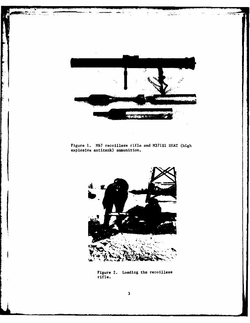
Figure 1. M67 recoilless rifle and M371E1 HEAT (highexplosive antitank) ammunition.
Figure 2. Loading the recoillessrifle.
3

IVW
Figure 3. Excavating the snow berm with a D-6 tractor.
Figure 4. Shaped charge jet trajectory exposed byexcavation (arrows).
4

Table 2. Measurements of shaped charge andinert round penetration.
Entrance
Penetra- cavity Crater Cratertion length depth radius Remarks(W) (W) (m) (m)
Shaped charge HEAT rounds
4 3.1 0.5 0.4 0.8 Air temp -4*C, snowj"I density 0.32 Mg/m 3 ,
front, 0.44 Mg/m 3 center,0.59 Mg/m 3 rear.
1.5 Impacted frozen soil in
snow.
3.4 0.5 0.7 0.93
2.9 - 0.8 0.9 Snow density 0.40 Mg/m
0.34 Mg/m3 , 0.44 Mg/m3,0.41 Mg/m
3 , 0.42 Mg/m3
rear.
3.0 0.9 0.8 Jet barely exited rear ofberm.
3.0 1.0 0.7 Snow den3ity 0.47 Mg/m3
front, 0.48 Mg/m 3 center,
0.50 Mg/m3 rear.
- 0.8 0.9
- 0.8 0.7
Inert rounds
2.4 N/A N/A N/A Air temp -4*C
2.8
2.0 (Flew 20 m after exit) Hit shallow section of
berm and exited rear.
2.0
1.5 (Flew 15 m after exit) Hit shallow section ofberm and exited rear.
occurred during the multi-impact phase of the testing. The round impactedhigh on the berm, penetrated about I m of snow and continued down range.The cause of detonation failure could not be determined.
Figure 4 illustrates a typical cross section of an impact area,showing the 2 to 3-cm-wide column of copper and explosive residue from
the shaped charge jet. As shown in Table 2, the maximum depth ofpenetration of the shaped charge jet of the HEAT rr-inds was about 3.0 m
5

in almost all cases. ThS approximate crater dimensions given in Table2 show that nearly 2.0 m of snow was compacted or expelled by eachimpact. Figure 5 shows a typical inert round trajectory after the snowwas excavated. Because the inert rounds were fired into a smallersection of the berm, two of the five rounds completely penetrated theberm and continued down-range 15 to 20 m (Fig. 6). As shown in Table 2,none of the inert rounds penetrated more than 3 m of packed snow. Thesetests demonstrated the capacity of snow to absorb both the high velocity,low mass products of an explosive charge and a relatively low velocity,high mass inert round.
The multiple impact test was conducted on a 2-m-wide, 6-m-deep,2 1/2-m-high section of the berm. Eight rounds were required to make anotch through the top of the berm. Although the repeated impacts musthave caused some disaggregation of the snow, it required all 22 roundsto reduce a 2-m-wide section of the berm to half its original height.
Observations of physical damage to the inert projectiles wereused to analyze roughly the forces and projectile decelerations generatedby impact. Figure 7 shows the nose sections of three recovered inertprojectiles. As typified by the projectile on the left, three of ther five inert projectiles exhibited no signs of plastic deformation and
only slight abrasion of paint on the aluminum nose cap. In a live shell,a piezoelectric sensor inside the nose cap activates the fuze when it isstrained (Fig. 8)*. As indicated by the absence of deformation to theprojectile at the left in Figure 7, impact in packed snow did not applya significant amount of pressure on the actuator. However, the sensoris so sensitive that 29 of 30 rounds detonated. In addition, only twoof the five rounds recovered showed evidence of impact with soil orother contaminants in the snow. This observation suggests that thepacked snow was detonating the live rounds.
Table 3 presents the data obtained from three inert projectilesfired at low angles into undisturbed snow. All three projectilesbroached and impacted again 200-400 m down range. Measurements of thetrenches formed in the snow show the projectiles penetrated to a maximumdepth of less than 30 cm in the 66-cm snow cover before they broached.
CONCLUSIONS
Based on the analysis of the data from these tests, the followingconclusions can be made.
1. Conservatively, three and a half meters of well-packed snow issufficient to absorb both the high velocity, concentrated explosiveproducts of HEAT rounds and the low velocity and high mass of inertrounds fired from a 90-mm recoilless rifle.
* HQ USAMC (1976) Engineering design handbook, recoilless weapon
systems. AMC Pamphlet 706-238.
6

Figure 5. Excavated inert round trajectory.
Figure 6. An inert round that penetrated the berm.
7

I
Figure 7. Nose caps of three 90-mm inert roundsrecovered from snow berm.
Figure 8. 90-mm HEAT cartridge M371EI.
8

.1
Table 3. Dimensions of trenches excavated by 90-mm inertrounds impacting at low angles and broaching.
C
-*-7
Shot Impact angle (0) A B C(mils)(degrees) (cm) (cm) (cm)
1 30 (1.70) 287 20.3 33.02 40 (2.20) 345 28.0 61.03 120 (6.70) 353 25.4 48.3
2. A snow embankment offers enough resistance to detonate HEATrounds even with the relatively low muzzle velocity (213 m/s) of theM67 recoilless rifle.
3. A multiple impact test series with 22 HEAT rounds showed thatsustained fire results in a suprisingly gradual collapse of a snowembankment. The snow embankment was only notched to half its originalheight by the combined impacts. This observation suggests that theenergy-absorbing properties of snow were not degraded (and perhapspossibly were enhanced) by repeated impacts.
RECOMMENDATIONS
A more comprehensive understanding of techniques for employing snowas a fortification material can offer potential advantages to militaryengineers operating in cold regions. Every winter, military engineersin many parts of the world must move tons of snow. With some basicplanning and little additional effort, this snow could be used toprotect parked aircraft, to build roadside fortifications, and toaid our combat forces in a variety of other ways.
9

APPENDIX
On 10 January 1976, a short delay in the CRREL testing schedulepermitted close observation of the Air National Guard's air-to-groundgunnery range.
The range actually consists of three separate ranges:
1. A bomb circle 58 m (175 ft) in diameter for practice exercisesusing jet fighter and close support aircraft armed withpractice bombs that emit a charge of smoke on impact.
2. A target 3 m (10 ft) in diameter marked by a suspended dragchute with electronic sensors to record hits by jet aircraftstrafing with 7.62-mm ball ammunition.
3. A similar strafing range for aircraft armed with 20-mm inertammunition.
In previous years the range had been closed during the wintermonths. This first season of winter operation presented many problemsfor the Air Force personnel, some of which parallel difficulties that
could be encountered on a winter battlefield.
The month of January began with several days of heavy snow at nearfreezing temperatures followed by a few days of clear weather. Then-10* to -25*C air temperatures with moderate winds and occasional snowsqualls left a smooth surface of undisturbed snow on the range. Theresult was a layer of snow 44 cm deep with a density of 0.22 to 0.26Mg/m 3 covered by a 1-cm-thick crust created by the sudden drop in airtemperature and compaction by the wind. There were 2 cm of light snowwith an approximate density of 0.10 to 0.15 Mg/m3 on top of the crust.The undisturbed snow provided excellent evidence of the effects ofbombardment when the first flight used the range after the weathercleared.
The soil beneath the snow had minimal frost penetration because theheavy snow accumulation provided insulation during the few days of lowair temperatures. The soil in the vicinity of the strafing targets wasnot affected because it had been covered by at least a foot of gravelduring the previous summer. The soil in the bomb circle appeared to bea saturated silty clay. The Air Force personnel described the area as avirtual bog in the summer. The bomb circle was heavily cratered by liverocket fire. Some of the craters were almost I m deep and were filledwith drifting snow at the time of the exercise.
The three F-100 fighters that used the range were each armed withsix practice bombs and 100-130 rounds of 20-mm inert ammunition forstrafing practice. The bombs were dropped from various heights, resultingin impact angles from 45 to 60 degrees. The attack angles on the strafingrange varied between 10 and 30 degrees.
11

On the bombing range, the range crew was having difficulty seeingthe smoke from the spotting charges that were supposed to mark theimpact points of the bombs. Approximately 15% of the bomb impacts werenot detected and were designated "no-spots" in the records. This problembegan after the first heavy snowfall.
On the day of the exercises, flying conditions were ideal, with anair temperature of 0 to -100 C. The schedule for the three F-100's beganwith bombing practice. As in previous exercises, three of the eighteen
drops could not be spotted and some were spotted only after a delay ofseveral seconds. Figures Al-A3 show three different types of post-impact bomb behavior. Figure Al illustrates a normal crater. Thisimpact was spotted from the oservation and control towers. Figure A2shows an entrance crater and a shear zone on the snow surface extendingseveral meters from the impact point. Dissection of the snow along thetrajectory revealed that the bomb had been deflected by the snow, glancedoff the soil, and detonated when it struck a high spot in the soilbeneath the snow, about 3 m from its impact point. Figure A3 shows thetrajectory of a bomb that broached from the snow after impact. Itapparently detonated about 25 m down range at the point indicated by thearrow. The craters in Figures A2 and A3 were found outside the bombcircle. The bombs in Figures A2 and A3 probably had a low impact angle,but past records indicated a higher incidence of "no-spots" at highimpact angles. From observations, it appeared that some of the practicebombs fell into the craters filled with deep snow within the bomb circleand either failed to detonate or had their detonation smothered by thesnow.
In Figure A4 it is hypothesized that at a high impact angle thebombs sank deep into the crater before making solid contact with thesoil. At the lower angles the bombs are more apt to strike the craterwall at a nearly perpendicular angle, penetrating less snow before
striking the soil. The low angle bombs were less likely to have visiblesmoke charges since the tails of the bombs were engulfed by snow. Fromthese observations we assumed that the more even ground outside the bombcircle encouraged "no-spots" at low impact angles and the crateredterrain of the bomb circle encouraged "no-spots" at high impact angles.
In an effort to correct this problem within the bomb circle, thearea was backgraded with a bulldozer. Some of the unfrozen soil waspushed into the craters on top of the snow. This procedure significantlyreduced the frequency of the "no-spots." The surface snow was com-pacted, reducing its insulating value. An accelerated freezing rate inthe soil was observed during the inspection of bomb craters from later
air strikes. The packed snow had also hardened to the point that itwould easily support the weight of a man, but it could not be determinedif any detonations had occurred on the packed snow surface. A briefsurvey after subsequent exercises revealed that most, if not all, of thespotting charge failures were now occurring outside the bomb circle in
the unpacked snow.
12

~14
Figure Al. A typical bomb crater with good detonation
of the spotting charge.
. VW
Figure A2. Apparent low angle impact in undisturbed
snow.
13

. -, . -, -- . . . ... .. -r' L, : ." -r ' -- ... . r ' , '- --.-'' "-' , ' P" "........... --.
Figure A3. Apparent low angle impact resulting inbroaching and detonation on second impact (arrow).
NMlh Angle Low A~
Figre 4.Hypothetical bobimpactsin the heavily cratered bomb circleshowing relationship between angle ofimpact and depth of penetration belowsnow surface.
14

On the strafing range the only problem had been some fouling of thetarget sensors by drifting snow, but the range crew had also noticednumerous spent rounds scattered over the surface of the snow in thevicinity of both the 20-mm and 7.62-mm targets following previousexercises. Many of these rounds showed little or no surface abrasionexcept for the marks of the rifling. The test crew recalled that duringthe summer exercises the projectiles had been severely damaged on impact
and that it had been unusual to find more than half of a projectile
still intact.
The two rounds shown in Figure A5 were retrieved from the snow.The round on the left was found in the immediate vicinity of the targetwhile the round to the right in the photo was found about 100 m downrange from the target. The projectile found near the target shows someabrasion of the painted surface while the projectile recovered downrange had negligible abrasion. In fact, there is so little physicaldamage to this projectile that there is a question as to whether or nota live round of this type would be detonated by the impact.
Figure A6 illustrates the ability of snow to alter the normal flightof a projectile; it shows two typical patterns that the 20-mm projectilescaused in the snow. The pattern in Figure A6a is typical for the roundthat was abraded. This pattern was observed in approximately three-quarters of the impacts. It appeared that the rounds passed through thesnow cover and glanced off the soil, which caused the abrasion, thentumbled through the snow, coming to rest between 70 and 120 cm from thepoint of impact.
The pattern of a round that continued down range after broaching isshown in Figure A6b. Note that the projectile veered to the right becauseof its right hand spin. This deflection was observed not only in theinitial pattern but also in subsequent patterns because many of theprojectiles skipped several times as they continued down range. Thehard crust 2 cm beneath the top of the snow appeared to encouragebroaching as the velocity of the projectiles decayed down range, but oninitial impact the round seemed to pass easily down through the crustlayer and then pass up through the crust layer just as easily. This is
indicated by the depth of the snow trenches of the initial impacts.
Figure A7b shows a round that broached and came to rest only about50 m from the target.
Figure A8 illustrates the pattern caused by a round when it finallystopped on a hillside about 150 m from the target (indicated by thearrow in Fig. A8a) and some 30 degrees to the right of its originaltrajectory. Notice that in Figure A8b the trajectory, instead of veeringto the right (as viewed from the target), abruptly veers to the left.The snow was brushed aside before the close-up (Fig. Aac) was taken. Itreveals that the round rolled sideways for the last 2 m. The obvious
implication is that the forward momentum had decayed, but that the roundwas still spinning, causing it to roll the last 2 m before it stopped.
15

Figure A5. Typical inert rounds retrieved on the 20-nmm
strafing range. Note the soft aluminum nose sectionthat was exposed when paint was abraded from theprojectile on the left.
a. Nonbroaching b. Broaching
Figure A6. Initial impact patterns typical for 20-mm (a) nonbroaching
and (b) broaching rounds.
16

0 4)
0
41c
0 $
.41
v46)
u0
0u
4J 44
0'4
0 w 4'
41. 0w.4) 41'
~~"' 000-
417.

bo 1
r40 p
$4 0
ow c
20 0.4
.10
U * r4o~ 0
-H. 0 c
180 -iC

The resumption of the scheduled testing prevented further observa-tions. The conclusion was that a snow cover will influence the terminalballistics of both bombs and bullets. It can not be estimated what theresults would be with live ammunition, but the observations here areworth reviewing if such a study is to be attempted.
H9
1'9