seat ateca vehicle fitting instructions mhfk 364
TRANSCRIPT

Seat AtecaVehicle Fitting Instructions
MHFK 364
Rev. C 2019
2
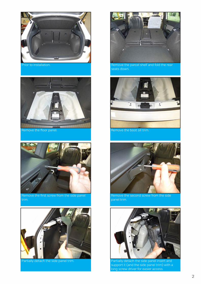
Prior to installation. Remove the parcel shelf and fold the rear seats down.
Remove the floor panel. Remove the boot sill trim.
Remove the first screw from the side panel trim.
Remove the second screw from the side panel trim.
Partially detach the side panel trim. Partially detach the side panel insert and support it (and the side panel trim) with a long screw driver for easier access.
3
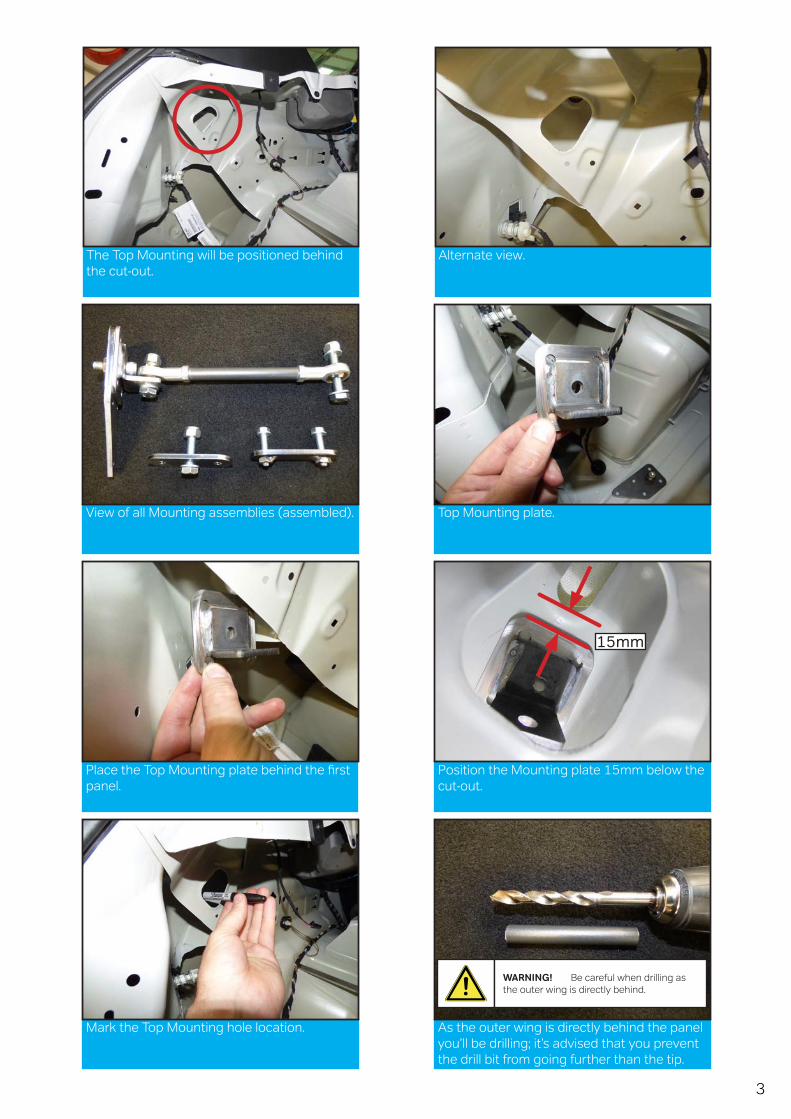
The Top Mounting will be positioned behind the cut-out.
Alternate view.
View of all Mounting assemblies (assembled). Top Mounting plate.
Place the Top Mounting plate behind the first panel.
Position the Mounting plate 15mm below the cut-out.
Mark the Top Mounting hole location. As the outer wing is directly behind the panel you’ll be drilling; it’s advised that you prevent the drill bit from going further than the tip.
15mm
WARNING! Be careful when drilling as the outer wing is directly behind.
4
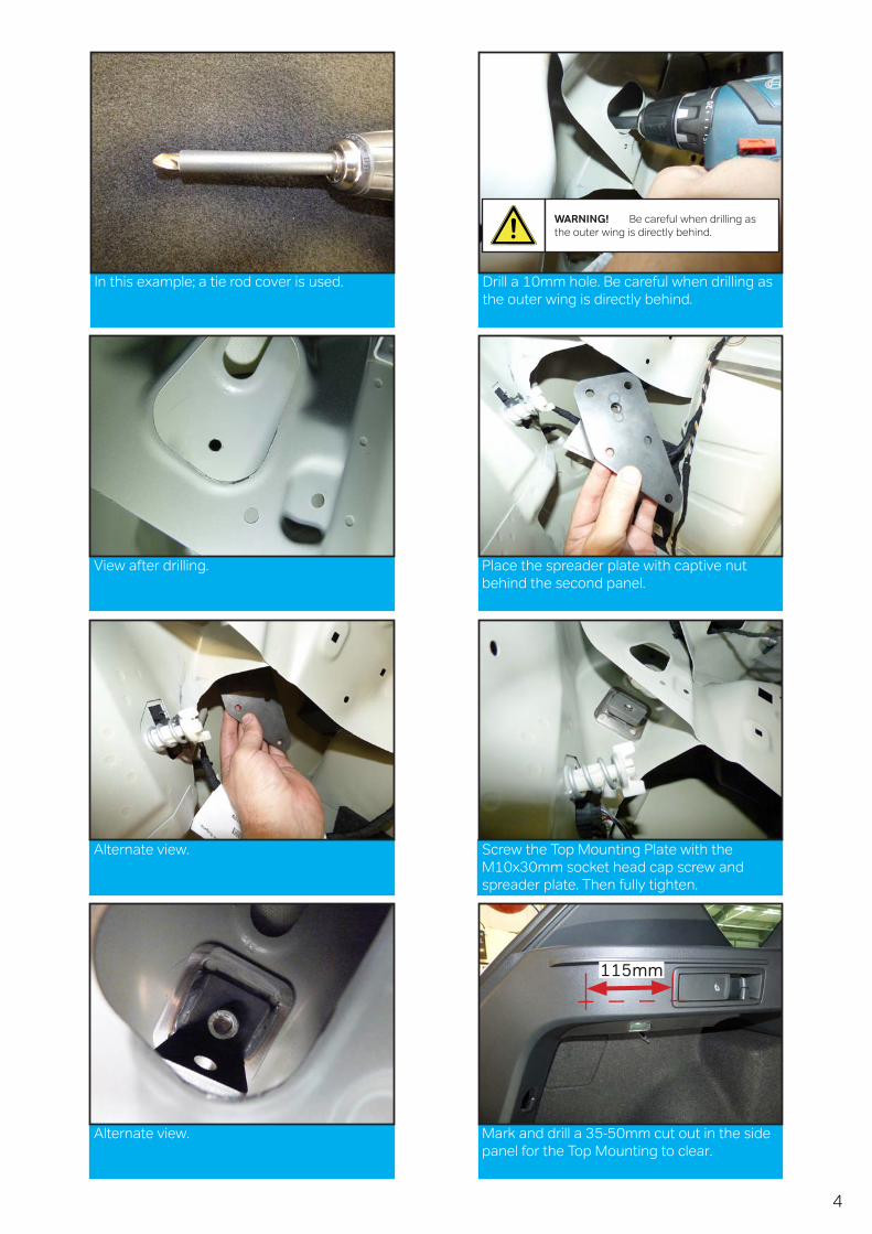
In this example; a tie rod cover is used. Drill a 10mm hole. Be careful when drilling as the outer wing is directly behind.
View after drilling. Place the spreader plate with captive nut behind the second panel.
Alternate view. Screw the Top Mounting Plate with the M10x30mm socket head cap screw and spreader plate. Then fully tighten.
Alternate view. Mark and drill a 35-50mm cut out in the side panel for the Top Mounting to clear.
115mm
WARNING! Be careful when drilling as the outer wing is directly behind.
5
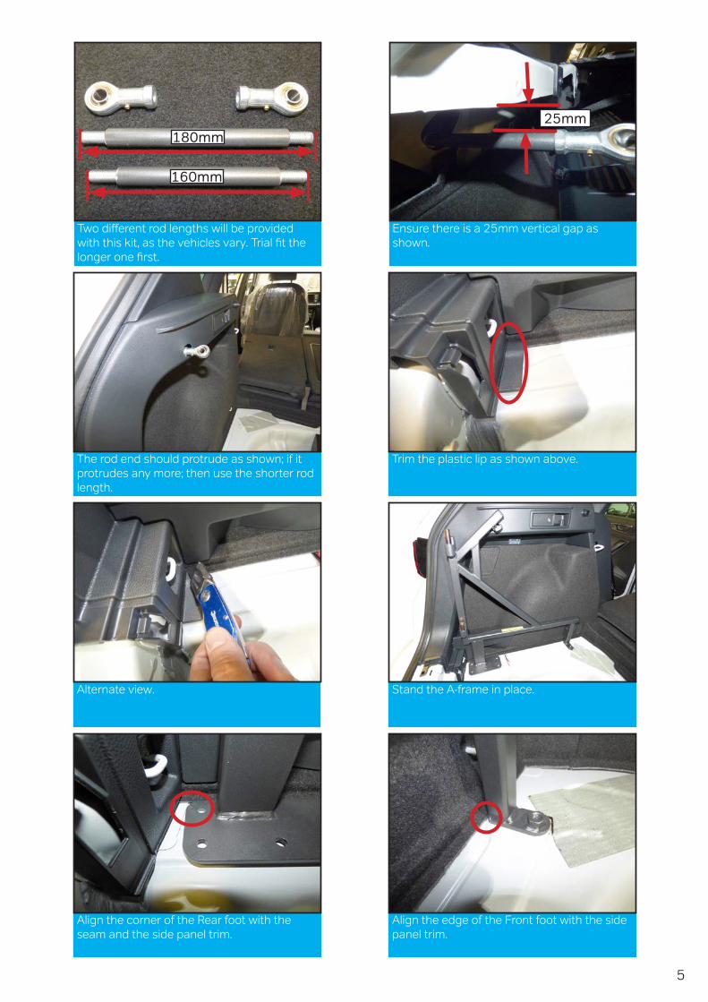
Two different rod lengths will be provided with this kit, as the vehicles vary. Trial fit the longer one first.
Ensure there is a 25mm vertical gap as shown.
The rod end should protrude as shown; if it protrudes any more; then use the shorter rod length.
Trim the plastic lip as shown above.
Alternate view. Stand the A-frame in place.
Align the corner of the Rear foot with the seam and the side panel trim.
Align the edge of the Front foot with the side panel trim.
25mm180mm
160mm
6
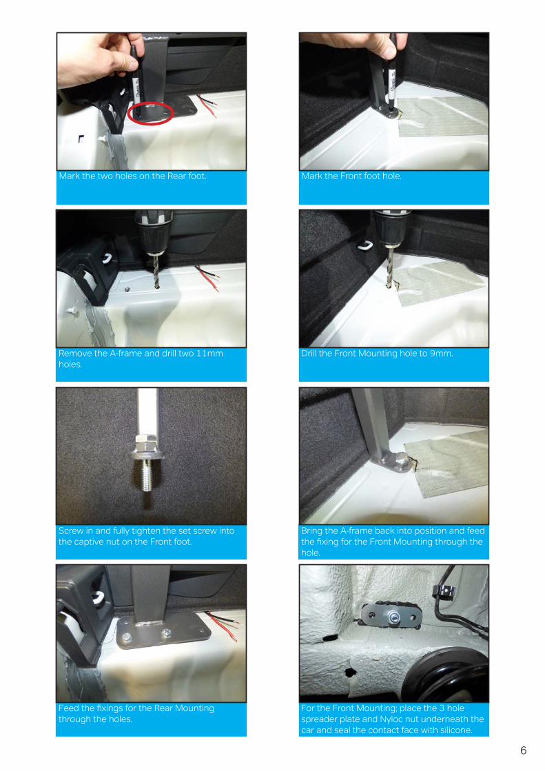
Mark the two holes on the Rear foot. Mark the Front foot hole.
Remove the A-frame and drill two 11mm holes.
Drill the Front Mounting hole to 9mm.
Screw in and fully tighten the set screw into the captive nut on the Front foot.
Bring the A-frame back into position and feed the fixing for the Front Mounting through the hole.
Feed the fixings for the Rear Mounting through the holes.
For the Front Mounting; place the 3 hole spreader plate and Nyloc nut underneath the car and seal the contact face with silicone.
7
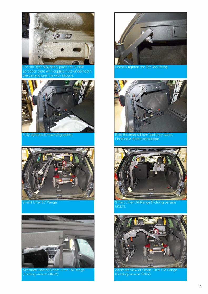
For the Rear Mounting; place the 2 hole spreader plate with captive nuts underneath the car and seal the with silicone.
Loosely tighten the Top Mounting.
Fully tighten all mounting points. Refit the boot sill trim and floor panel.Finished A-frame installation.
Smart Lifter LC Range. Smart Lifter LM Range (Folding versionONLY).
Alternate view of Smart Lifter LM Range (Folding version ONLY).
Alternate view of Smart Lifter LM Range (Folding version ONLY).
8
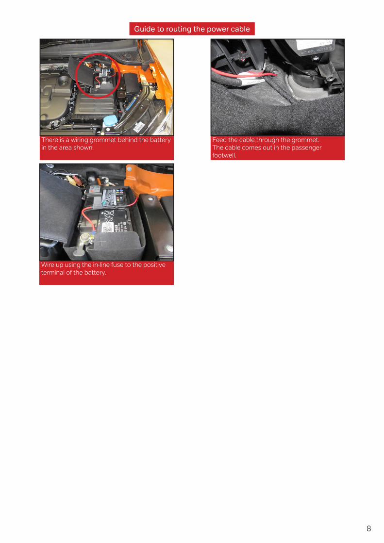
There is a wiring grommet behind the battery in the area shown.
Feed the cable through the grommet. The cable comes out in the passenger footwell.
Wire up using the in-line fuse to the positive terminal of the battery.
Guide to routing the power cable