sears - appliance parts | replacement water filters ... mts! full one year warranty on craftsman...
TRANSCRIPT

SEARSOWNER'SMANUAL
MODELNO.390.2511 82
3_90_.251982
390.252282
CAUTION:Read and Follow
All Safely RulesandOperating InstructionsBefore FirstUse ofThisProduct.
Save ThisManual ForFutureReference.
CRAFTSMANMODEL NO.390.251182
CRAFTSMANPROFESSIONAL
MODEL NOS.390.251982390.252252
CRRFTSMgN°"HYDROGLASS ''®CONVERTIBLE DEEPWELL JET PUMP• Safety Instructions• Installation
• Operation
• Troubleshooting
• Repair Parts
IIIIII I
Sears, Roebuck and Co., Hoffman Estates, IL-60179 U.S.A.
PRINTED IN U.S.A. Form No. F642-9806 (Rev. 4/24/98)
READ AND FOLLOW SAFETY INSTRUCTIONS!
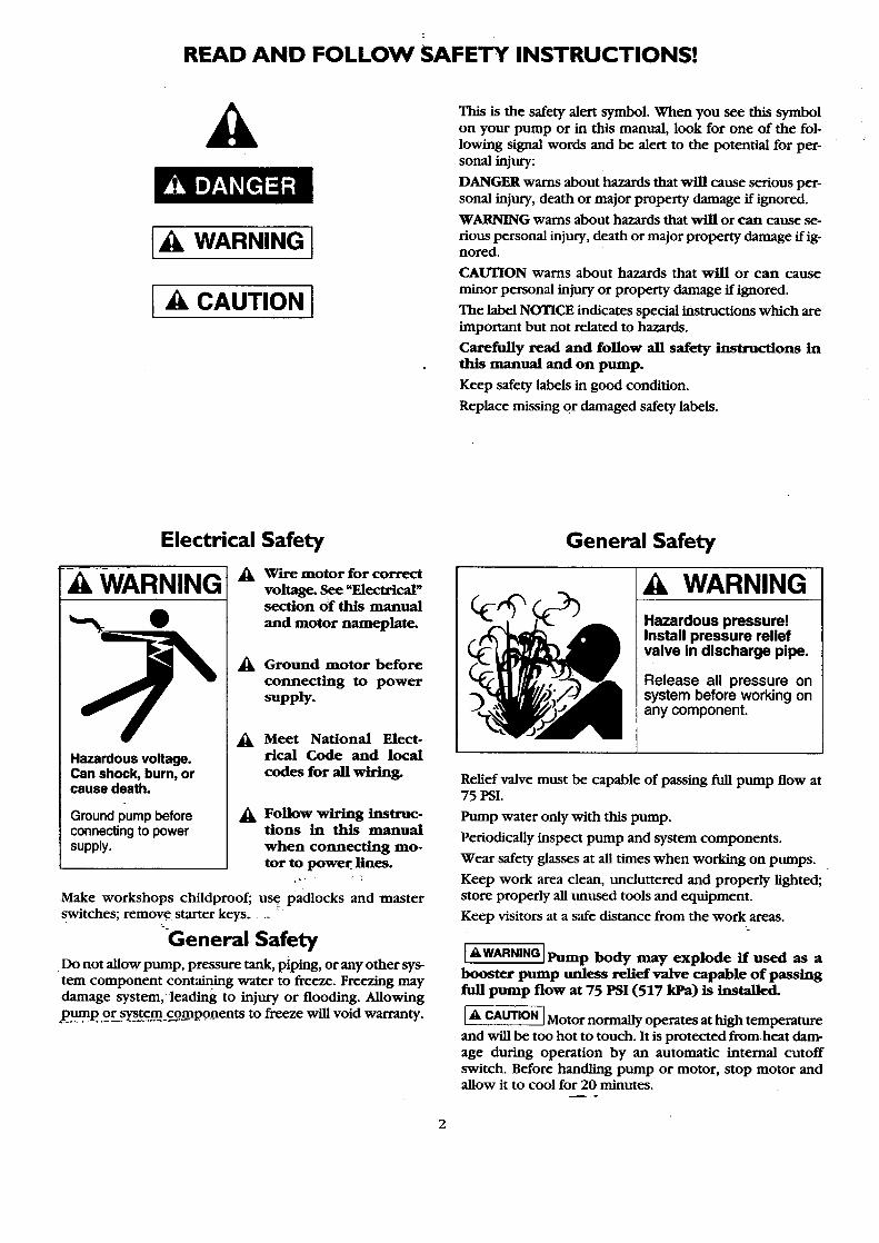
This is the safety alert symbol. When you see this symbolon your pump or in this manual, look for one of the fol-lowing signal words and be alert to the potential for per-sonal injury:
DANGER warns about hazards that will cause serious per-sonal injury, death or major property damage if ignored.
WARNING warns about hazards that will or can cause se-
rious personal injury, death or major property damage if ig-nored.
CAUTION warns about hazards that will or can cause
minor personal injury or property damage if ignored.
The label NOTICE indicates spedal instructions which are
important but not related to hazards.
Carefully read and follow all safety instructions inthis manual and on pump.
Keep safety labels in good condition.
Replace missing or damaged safety labels.
Electrical Safety
WARNING
O
Hazardous voltage.Can shock, burn, orcause death.
Ground pump beforeconnecting to powersupply.
_k Wire motor for correctvoltage. See "Electrical"section Of this manual
and motor nameplate.
_k Ground motor before
connecting to powersupply.
_k Meet National Elect-rical Code and local
codes for all wiring.
_k Follow wiring instruc-tions in this manualwhen connecting mo-tor to power lines.
Make workshops childproof; use padlocks and masterswitches; remove starter keys ....
General SafetyDo not allow pump, pressure tank, piping, or any other sys-tem component containing water to freeze. Freezing maydamage system, leading to injury or flooding. Allowing
pum. p. or _¢m_c0mpo.nents to freeze will void warranty.
General Safety
WARNING
Hazardous pressure!Install pressure reliefvalve in discharge pipe.
Release all pressure onsystem before working onany component.
Relief valve must be capable of passing full pump flow at75 PSI.
Pump water only with this pump.
Periodically inspect pump and system components.
Wear safety glasses at all times when working on pumps.
Keep work area clean, uncluttered and properly lighted;store properly all unused tools and equipment.
Keep visitors at a safe distance from the work areas.
I_'WARNINGI]Pump body may explode if used as a
booste_r pump unless relief valve capable of passingfull pump flow at 75 PSI (517 kPa) is installed.
[& CAUTION IMotor normally operates at high temperature
and will be too hot to touch. It is protected from heat dam-age during operation by an automatic internal cutoffswitch. Before handling pump or motor, stop motor andallow it to cool for 20 minutes.

co mTs!
FULL ONE YEAR WARRANTY ON CRAFTSMAN WELL PUMPSFor one year from the date of purchase Sears will replace or replace this pump if defective in materials or workmanship.
LIMITED WARRANTY ON CRAFTSMAN PROFESSIONAL HYDROGLASS WELL PUMPSAfter one year and through three years from the date of purchase Sears will furnish, free of charge, a replacement part for anydefective part. You pay for labor.
LIMITED WARRANTY ON CRAFTSMAN HYDROGLASS WELL PUMPSAfter one year and through two years from the date of purchase. Sears will furnish, flee of eharge a replacement par for anydefective part. You pay for labor.
This wan'amy does not cover repair or replacement parts necessary because of abuse or neglect including failure to install adjustand operatethis pump according to the instructions in the owners manual.
LIMITATION OF LIABILITYSEARS WILL NOT BE LIABLE FOR LOSS OR DAMAGE TO PROPERTY OR ANY INCIDENTAL OR
CONSEQUENTIOL LOSS OR EXPENSE FROM PROPERTY DAMAGE DUE DIRECTLY OR INDIRECTLY FROMTHE USE OF THIS PRODUCT
Some states do not allow the exclusion or limitation of incidental or consequential damage so the above limitation or exelusionmay not apply to you,
WARRANTY SERVICE IS AVAILABLE BY SIMPLY CONTACTING THE SEARS SERVICECENTER/DEPARTMENT IN THE UNITED STATES
This warranty applies only while the product is in use in the United States
This warranty gives you specific legal rights and you also have other rights which vary from state to state.
Sears, Roebuck and Co., Dept. 817WA, Hoffinan Estates, I160179_
:i:i! ::i ¸ i :¸ ii :iii: L::
2. Check:y_os l_ e_e_cat_!_:co_,befo_ tr_tana_tiota.If your !_ €od_ :._,_ot:_weO_ :yo .urpmp: will
not wo_ to.itSelf rated ¢alm6t_i l.fin doobt,-.contact-_oar local Power_m_
hag, prop and:welt<@_. :
ptanp,
5. Aiwaystest_eweLlWaterforp_ybeforeT_ L_ck
w_tn_oea_heath _at c_rt_san_p_au_,
6_ BefOre _ or:ser_cing yout:p_p:,'BECERTAINpump power s6urce.!is _ _nnecteO.
8.. Comple)e p_?::and:piping- syslem:_ _ pr0te_ted
9. Make SUre!theltne_O!tage:and'_eq_ofthe el_cal
dr_t:supp!_-_e:wi_ :the.motor w_. ]f_moto r is_a.voltage _e, _ surm it isw_:eor_ca_for-your:power_ply,
lO_ _et-_ _d _g s_ _ _a_ _o:_o_mot_tton, Reeo_r_r_ded fusingamt_size:dataisltn t_mamntl: ....

INSTALLATION - DEEP WELL
1"DISCHARGETO SERVICE
PRIMING PLUG '_
f PRESSURE SWITCH _
F
CAPTIVEAIFI_ TANK
" REGULATOR
PLASTIC1-1/4" SUCTION LINE PIPE
TANK PIPING
1-1/4' STEEL PIPE
CHECK VALVE
1"PLASTIC PIPE-
1-1/4"
1=
PLASTIC PIPE
WELL SEAL
ADAPTERS
END VIEW SIDE VIEW
SINGLE PIPEINSTALLATION
CHECK VALVE _AND STRAINER
DOUBLE PIPEINSTALLATION
Fi-g_-re- I _'Captive Air e Pressure Tank Installation - Deep Well
/
1" DISCHARGETO SERVICE
PRIMING
PRESSURESWITCH "_
STANDARD PRESSURE TANK
END VIEW SIDE VIEW
REGULATOR
PLASTICPIPE
1-1/4"
_1-1/4 SUCTION LINEI 1"DRIVE UNE
VOLUME CONTROL VERTICAL CASINGTUBING ADAPTER
AIR VOLUMECONTROL
1-114
JET WITH BUILT-IN
SINGLE PIPEINSTALLATION
Figure 2 - Standard Pressure Tank Installation - Deep Well
DOUBLE PIPEINSTALLATION

INSTALLATION - SHALLOW WELL
PRIMING PLUG
PRESSURE SWITCH
1"DISCHARGETO SERVICE
SHALLOW WELL JET
CHECK VALVEI-I14"
END vIEW
(OPTIONAL CHECK
TO VALVE)
SIDE VIEW DRIVEN POINT
PIPE ADAPTER
WELL SEAL ,_
1-1/4"PLASTIC PIPE
FOOT VALVEAND STRAINER
\
DUG OR CASED WELL
Figu_3---C_tive AiP Pressure Tank Installation- Shallow Well
1"DISCHARGETO SERVICE "_
PRESSU_I_ING PLUG_
SWITCH "__
STANDARD PRESSURE TANK
PRESSURE REGULATOR
=_'_ SHALLOW WELL JET
CK VALVE
Y _,_ PLASTICPIPE'% ADAPTER
AIR VOLUME
ROLTUBING
r AIR'VOLUME
CONTROL
END VIEW SIDE VIEW
I-I14"
ALI_;PLASTIC PIP(_OPTION PIPEADAPTER
CHECk _VALVE .... "_'_'_'_
1-1/4"1-114"STEEL [1 PLASTIC PIPE.
DRIVE PIPE"-"_I IDhIVE---_t'l
COUPING _ FOOT VALVE
W AND STRAINER
WELL POINT_...._
DRIVEN POINT DUG OR CASED WELL
Figure 4 - Standard Pressure Tank Installation - Shallow Well

INSTALLATION
NOTICE: Use Teflon tape suppfied with the pump or Plasto-
Joint Stikl for.making all pipe-thread connections to the
pump itself. To avoid stress-cracking, do not use pipe jointcompounds on the pump.
1. Wrap male pipe threads being attached to pump with oneor two layers of Teflon tape. Cover entire threaded por-
tion of pipe.
2. Do not overtighten threaded fittings in the plastic pump.
Be sure you do not try to tighten joint past thread stop inpump port!
3. If leaks occur, remove fittings, clean off old tape, rewrapwith one to two layers of tape and remake the connec-tion. If joint still leaks, replace the fittings (fittings may beundersized).
4. -Be sure to support all piping connected to the System.
MAJOR COMPONENTS AND WHATTHEY DO
Tank and Air Volume Control
The tank serves two functions. It provides a reservoir ofwater, some of which can be drawn through the house fix-ture before the pump must start, and it maintains a cushionof air under pressure.
When Captive Air* Tanks are used, no air volume control isnecessary. This tank contains a permanent pre.charge of air.
When a Standard Tank is used, an air volume control addsair_to, the_tank when it is needed. See instructions included
with Air Volume Control for details on installation and op-eration.
Pressure Switch
The pressure switch provides for automatic operation.
MODEL NO. PUMP STARTS AT PUMP STOPS AT
390.251182 30 Pounds 50 Pounds
390.251982 40 Pounds 60 Pounds
390.252282 40 Pounds 60 Pounds
Impeller, Jet and Pressure Regulator
The impeller of the pump rotates with the motor shaft, cans-ing the water to fly out from its rim by centrifugal force. Therotation of the impeller creates a vacuum which _pulls" inmore water. Part of the water is diverted back to the jetwhere it again passes through the nozzle and venturi - cre-ating additional vacuum to draw in more water and deliver-ing it at high pressure to the impeller.
In a deep well installation, the jet assembly is submergedin the well because the vertical distance to the water level
exceeds the suction lift of the pump.
Adjustment of the pressure regulator causes the right
amount of water to be diverted back to the jet for the mostefficient operation.
'lake Chemical Co., Chicago, Illin°is
In a shallow well installation, the jet assembly is attached
directly to the pump because the vacuum created will pullwater to the pump.
The pressure regulator may be used to restrict the flow ofwater in a shallow well system if the SEARS convertiblepump produces more water than the well can produce.
DEEP WELL PUMP INSTALLATION
(Figures I & 2, Page 4)
In a deep well installation, the jet assembly is submerged inthe well because the vertical distance to the water level ex-
ceeds the suction lift of the pump. A single pipe system mustbe used in 2" and 3_ wells. A double pipe system must beused in 4 _ or larger wells.
Follow instructions packed with jet package for proper noz-zle and venturi combination for your pumping depth.
DOUBLE PIPE JET
when a double pipe jet is selected, 2 pipes are used in thewell. One is the suction pipe, and the other, the pressurepipe. Plastic pipe is ideal for double pipe installations, dueto its light weight and easy installation.
Use 100 pound flexible plastic pipe on horizontal jet pumps.
TO INSTALL 4" DOUBLE PIPE JET
First, inspect jet to make sure no foreign matter has enteredthe openings.
Be certain no foreign matter enters pipe openings while in-stalling the unit.
Plastic Pipe Installations
1. Attach a foot valve (not furnished) to the jet with a shortnipple.
2. Before installing, be certain foot valve operates freely.
3. A special plastic pipe adapter is included with the jetwhich screws into the 1-1/4 _ suction tapping over theventuri.
4. Assemble a plastic pipe adapter (not furnished) into 1_tapping in the jet body.
5. Use sufficient length of plastic pipe to place the jet 10-15feet below the lowest drawdown water level. This is the
level to which the water in the well will drop while beingpumped continuously.
6. Tighten all hose clamps securely. A sanitary well seal is re-
quired on top of the well casing. Use steel nipples and el-bows or specialized galvanized steel elbows to go throughthe well seat. Use plastic pipe adapters where special el-bows are not used.
6

INSTALLATION
STEEL PIPING INSTALLATIONS
When steel pipe is-used to install the jet, be sure all pipesare clean and the ends are reamed. Screw both 1-1/4 _ NPT
suction pipe and 1" NPT drive pipe directly into the jetbody. The special adapter nipple furnished with the jet isnot used on steel pipe installations, and should be discarded.Add sufficient piping, using pipe thread compound on thejoints until proper depth is reached.
NOTICE: Pipe compound can damage plastic components
in pump. Use only Teflon tape or Plasto-Joint Stikl whenconnecting pipe to pump.
SINGLE PIPE JETS - 2" OR 3" WELLS
Be_foreinstalling jet in well, it is necessary to soften jetleathers by soaking in water for a minimum of one hour.
Single pipe-jets must be installed with steel suction pipingin the well. Make sure all pipes are clean and ends arereamed before lowering any piping into the well. Lookthrough pipe to make certain there are no obstructions.
During the process of lowering pipe into the well, always in-stall coupling on top end of pipe and above clamp. This willprevent accidental dropping of pipe into well.
Attach the jet to the first length of suction pipe 1-1/4" (NPT).
Use turned couplings (furnished) on 2" wells. Standard cou-plings may be used for suction piping on 3" wells. Use pipecompound on male threads only.
Tigl3t.en gac!_l_¢ngth of pipe as it is lowered into the well.Lower it to proper depth which is 10-15 feet below thedrawdown water level. This is the level to which the water
will drop while the well is being pumped continuously.
NOTICE: Due to normal irregularities in the leather of the
cup seals and the inner walls of the drop pipe, 2_ packer jetsdo not form a perfect seal. In a dormant system, water willleak back into well over time and pump will normally startand cycle to maintain system pressure level.
PRIMING PIPE (OR PIPES) IN WELL
Fill piping in well with water as each length is added, or after
piping is complete in well. This serves to double check forleaks in piping and foot valve, and simplifies final priming ofpump.
INSTALLING CASING ADAPTER
Slide adapter on to well casing as far as it will go. Tightenthree bolts to seal the adapter to the casing. Place a 1_ nip-pie of proper length in the drive pipe opening in the ciksingadapter, and tighten top nuts. This will seal the glands on toboth suction and drive piping. Add elbows and flexible pipeadapters for horizontal installations.
'Lake Chemical Co., Chicago, Illinois.
SHALLOW WELL INSTALLATIONAND OPERATION
Installing the Pump on a Shallow Well
A shallow well jet is available for use when the SEARS jetpump is installed on wells 20 feet or less to drawdown waterlevel.
Install this jet as follows:
a. Loosen the stainless steel clamp until it fits over the flangeon the jet body.
b. Place O-Ring in circular groove on face of suction-drive
line flange. If necessary, use petroleum jelly to hold inplace.
c. Venturi that protrudes from the jet body must be insertedin top (1-1/4" NP'I') tapping. For ease of assembly, lubri-cate the small O-Ring on the end of the venturi and pushthe shallow well jet assembly into place.
d. Align lugs on jet body with slots in pump.
e. Place clamp over the flanges and tighten securely.
For standard tank installations, an air volume control is nec-
essary and is connected to the 1/8" tapping in the jet body.Connect as shown in installation drawing, Figure 4, Page 5.
PIPING IN THE WELL
A shallow well jet pump can be installed on a dug well,drilled well or with a driven point. SEARS shallow well jetpumps have a built-in check valve. In a dug or cased well, afoot valve and strainer is recommended and should be in-stalled 5 to 10 feet below the lowest level to which the water
will drop while the pump is operating (pumping waterlevel). See Figure 4, Page 5. Your well driller can furnish thisinformation. The strainer should not be too close to the bot-
tom, or sediment may clog it. Before installing foot valve,check to see if it works freely.
When using a foot valve, a priming tee and a plug as shownin Figure 7 is recommended.
Figure 7

INSTALLATION "
I--IA CAUTIONINEVER run pump dry. Running pump with-
out water may-overheat unit, damaging seals and possibly
burning persons handling pump.
IAWARNING]_ run pump against closed dis-
charge. To do so can boil water inside pump, causing haz-ardous pressure in unit and possible scalding to personshandling pump.
Be sure the total lift from the pumping water level to thepump does not exceed 20 feet if the pump is over the well,or less if the pump is offset from the well. Both figures arefor sea level - the maximum lift at which the pump can op-erate satisfactorily, decreases with the elevation at the ap-proximate rate of 1 foot per 1,000 feet of elevation; thus, ffthe lift is 17 feet and your elevation is 3,000 feet above sealevel, you would then be pumping 17 plus 3 or 20 feet,which is still satisfactory for shallow well pumping.
Horizontal Piping From Well To Pump
On well point installations where the horizontal piping ismore than 25 feet, a check valve should be installed as
shown in Figures 3 and 4, Page 5.
When the pump is offset more than 25 feet from the well,horizontal piping should be increased in size to reduced fric-tion losses. In no case should the offset piping be smallerthan the suction tapping of the pump.
Horizontal Offset Piping Sizes
S_.ha!!..Qw,_W.ellJets
1-1/4" 1-1/2" 2"
Up to 25 Ft. 25 to 50 Ft. 50 to 200 Ft.
Horizontal Offset Piping Sizes
Deep Well Jets
Up to 50 Ft. 50 to 100 Ft. 100 to 300 Ft.Suct. Drive Suct. Drive Suct. Drive
1-1/4 1 1-1/2 1-1/4 2 1-1/2
Discharge Pipe Sizes
When the pump is set a distance from the house, barns, orother points of water use, the discharge pipe size should beincreased to reduce pressure losses.
1" 1-1/4"
Up to 25 Ft. 25 to 100 Ft.
1-1/2"
100 to 600 Ft.
PUMP INSTALLATION
SEARS jet pumps can be used with Captive Air* Tanks asshown in Figure 1, Page 4, and Figure 3, Page 5.
For mounting pump to tank, order tank fittings Kit No. 2788.
Captive _ Tanks are pre-charged with air at the factory.Check operating instructions with tank to determine if aircharge needs adjustment.
Model 390.251182 requires 30 pounds air charge forproper operation and Models 390.251982 and390.252282 require 40 pounds for proper operation.
EMERGENCY POWER
In some areas and with some installations, an emergencypower supply to guard against power failure is a good idea.
If you install an engine-generator set for emergency backuppower for your pump, supply the generator set manufac-
turer with the nameplate data from the pump motor. He willthen be able to provide a generator of the correct size to
power your pump. Also, be sure to add the load from anyother accessories (such as lights) that may be on the samecircuit.
Recommended Fusing and Wiring Data
PumpModel
390.251182
390.251982
390.252282
MotorHorse-power
1/2
3/4
Volts
115
230
115
230
115
230
Max.Load
Amperes
9.4
4.7
12.2
6.1
14.8
7.4
Branch*
DelayedFuse
RatingAmps
15.0
15.0
15.0
15.0
20.0
15.0
Distance in Feet FromMotor to Meter
0 51 101 201.to to to to50 100 200 300
Wire Size --
14 14 10 10
14 14 14 14
12 12 10 8
14 14 14 14
12 12 8 6
14 14 14 14
* Time delayed fuses are recommended instead of fuses in any motor circuit.

ELECTRICAL
_k Di_onnect power before working on pump, motor, pressure switch, or wiring.
Your Motor Terminal Board (under the motor end cover)and Pressure Switch look like one of those shown below.
Convert to 115 Volts as shown. Do not change motor wiring
if line voltage is 230 Volts or if you have a single voltagemotor. Connect power supply as shown for your type ofswitch and your supply voltage.
230 Volt to 115 Volt Conversion, Plug-inType:
1. Pull plug 2. Plug in againstraight witharrowout from on plugterminal pointingtoboard; '115 Volts'.
2,
Motor wires connect here.
Power supply wires connecthere.230 Volt: Connect2 hot wires (blackand red)here and cap the white (neutral)wire. Itdoesnot matter whichwire goes to which screw.115 Volt: Connectone hotwire (blackor redto one of thesescrews (it doesn'tmatterwhich one). Connect the white (neutral)wireto the other screw.Cap any remainingblack or red wires.
Clamp the power cable to preventstraiRon the terminalscrews.
Connect the green (or bare copper)groundwireto the green ground screw.
230 Volt to 115 VoltConversion, Spade ConnectorType:
1. Move black wire 2. Move white wire 3. Change Complete:from A to LI. withblack tracer
from B to A.
Motor wires connect here.
_pplywires connect here.230 Volt: Connect 2 hotwires (black and red)here and cap the white (neutral)wire. It doesnotmatter whichwire goes to whichscrew.115 Volt: Connectone hot wire (blackor red)to one of these screws(it doesnl matterwhich one). Connect thewhite (neutral)wireto the otherscrew. Cap any remainingblackor red wires.
) the powercable to preventstrainon the terminalscrews.
Connect the green (or bare copper) groundwireto the green groundscrew. 3187
Figure 8 - Motor wiring connections through Pressure Switch. Match motor voltage to line voltage.
I_kWARNING[ Haz_dous voltage. Can shock, burn,or kilL Connect ground wire before connecting
power supply wires. Use the wire size (indudingthe ground wire) specified in the wiring chart. Ifpossible, connect the pump to a separate branch cir-
cuit with no other appliances on it.
IAWARNINGI Explosion hazard. Do not ground to
a gas supply line.
Wiring Connections
I_'WARNING I Fire hazard. Incorrect voltage can cause
a fire or seriouslydamage the motor and voids the war-
ranty. The supply voltage must be within +10% of themotor nameplate voltage.
NOTICE- Dual-voltage motors are factory wired for
230 volts. If necessary, reconnect the motor for 115volts, as shown. Do not alter the wiring in single volt-
age motors.
Install, ground, wire, and maintain your pump in com-
pliance with the National Electrical Code (NEC) or the_. Gamedia_ Electrical Code (CEC), as applicable, and
with all local codes and ordinances that apply. Consultyour local building inspector for code information.
Connection Procedure
.
°
.
.
Connect the ground wire first as shown in Figure 8.The ground wire must be a solid copper wire at leastas large as the power supply wires.
There must be a solid metal connection between the
pressure switch and the motor for motor groundingprotection. If the pressure switch is not connectedto the motor, connect the green ground screw in theswitch to the green ground screw under the motorend cover. Use a solid copper wire at least as largeas the power supply wires.
Connect the ground wire to a grounded lead in a ser-vice panel, to a metal underground water pipe, to ametal well casing at least ten feet (3M) long, or to aground electrode provided by the power companyor the hydro authority.
Connect the power supply wires to the pressureswitch as shown in Figure 8.
9

OPERATION MAINTENANCE
PRIMING THE SHALLOW WELL PUMP
TO PREVENT-DAMAGE TO INTERNAL PARTS, DO NOTSTART MOTOR UNTIL PUMP HAS BEEN FILLED WITHWATER.
1. Be sure pressure regulator located on pump body is open
at all times during priming and running. Turn counter-clockwise all the way.
2. Remove priming plug. Fill pump with water. Replacepriming plug. If a priming tee and plug have been pro-vided for a long horizontal run, be sure this line is filled
and the plug replaced, using pipe compound on plugthreads. See Figure 7, Page 7.
3. Start the pump and run for approximately thirty (30) sec-onds. Stop pump, remove prime plug and refill withwater. Replace prime plug and gauge and restart pump.Water will be pumped in a few minutes, the time de-
pending on the depth to water and length of horizontalrun. If pump does not prime, check for a possible leak onthe suction side of pump. Check to be sure suction lift -distance from water level to pump - does not exceedtwenty (20) feet.
PRIMING THE DEEP WELL PUMP
TO PREVENT DAMAGE TO INTERNAL PARTS, DO NOTSTART MOTOR UNTIL PUMP HAS BEEN FILLED WITHWATER.
1. Remove the priming plug. Open pressure regulator (turn.... -c-6uTlte_r_lockwise) located on the pump body. Fill pump
and piping with water and replace plug and tighten onlyuntil it seals.
NOTICE: For location of pressure regulator, see InstallationDiagrams on Pages 4 and 5.
2. Close the pressure regulator (turn clockwise).
3. Open several faucets in the house or near the tank to pre-vent pressure build up in tank.
4. Start pump. Pressure should build up rapidly as the jet andpump prime. Pressure will be in excess of 60 pounds. Ifthis fails to happen, repeat 2 and 3 above.
5. Once unit has primed on pressure has stabilized, slowlyopen (turn counter-clockwise) the pressure regulator andwater Will begin to be pumped into tank.
6. Continue to open pressure regulator until pressure falters(becomes erratic). At this point, close (turn clockwise)the pressure regulator slightly until pressure stabilizes.Close faucets and allow pump to pressurize the tank andshut off ........
7. To insure pump is operating properly, alternately openand close faucets in system. With faucets open, pressurewill drop until pressure switch starts pump; and withfaucets closed, pressure will build up until pressureswitch shuts off pump.
8. There are certain conditions of deep well operationwhereby the pressure regulator can be completely openwithout any faltering of pressure and if so, pump shouldbe operated in this manner.
LUBRICATION
It is not necessary to lubricate the pump or its motor. Themotor has two ball bearings lubricated for life. The me-chanical shaft seal in the pump is water lubricated and self-adjusting.
DRAINING FOR WINTER
When the pump is to be disconnected from service, or is indanger of freezing, it should be drained. The pump has a
drain cock which must be opened. Remove the primingplug to vent the pump. Drain the pressure tank. Drain all pip-ing to a point below the freeze line.
To drain an air volume control, remove AVC tubing and turn(loosen) it 180 ° on the 1/4" pipe fitting in the tank. This willpermit any water remaining in the air volume control todrain back into the tank.
DISASSEMBLY AND ASSEMBLY OF PUMP
The SEARS Hydroglass ®pump is designed for ease in servic-ing and maintenance.
1. Disassemble pump as follows:
A. Disconnect power.
B. Drain pump by opening drain cock on bottom ofpump body and remove pressure switch tubing fromfitting on top of pump body. This will allow air to re-place the water in the pump.
C. Remove clamp, Key No. 11, Page 16, which holds thetwo pump halves together.
D. Remove pump base mounting bolts. Motor assemblyand back half of pump can now be pulled away frompump front half. Carefully remove O-Ring and place ina clean area. Inside of pump is now accessible for ser-vice.
2. Reassembly of pump.
A. With a clean doth, wipe out all foreign material fromthe large O-Ring groove on the pump back half. Alsowipe clean the large O-Ring and also the small O-Ring,Key No. 6, Page 16 on the diffuser, Key No. 10, Page16. This will insure a good tight seal.
B. Lubricate O-Rings with petroleum jelly for ease of as-sembly. Place large O-Ring in groove.
C. Pump halves can now be slid together until they areparallel and are as close together as possible.
D. BE SURE inside of clamp is clean. Place clamp onpump halves and snug up. Alternately tighten clampscrew and tap around outside of clamp with a plasticmallet. This will insure proper seating of O-Ring anddamp.
E. Assemble base mounting bolts. Reconnect pressureswitch tubing and tighten drain cock.
F. Reprime pump and turn on power.
10

SERVICE
REMOVING MOTOR FOR SERVICEAND REPLACING SHAFT SEAL
Should repair or replacement of motor or seal be necessary,the pump need not be disconnected from the piping.
(If it is necessary to repair or replace the motor, ALWAYS re-
place the shaft seal, Key No. 7, Page 16. Therefore, we sug-gest that you order this item and have on hand for futureuse).
Remove motor as follows:
1. Disassemble pump per disassembly instruction on Page10.
2. Remove diffuser and impeller, Key Nos. 8 and 9, Page 16,from pump back half.
--Rentove Impeller as follows:
1. Loosen two-machine screws and remove the motorcanopy, Key No. 1A, Page 16.
2. Partially unscrew capacitor clamp and move capacitor toone side.
3. Place a 7/16" open end wrench on the motor shaft flat.
4. To remove, turn the impeller counterclockwise (whenfacing impeller).
The seal consists of two parts, a rotating member and a float-ing seat.NOTICE: The highly polished and lapped faces of the seal areeasily damaged. Read instructions carefully.
5_ --Remove pump back half from motor by unscrewing four(4) nuts, Key No. 20, Page 16, and pry back half off ofmotor by inserting two (2) screwdrivers between the
back pump half and the motor flange. Rotating portion ofseal will now come off of shaft. Motor is now separatedfrom pump (see Figure 9).
6. Lay back half of pump (large surface down) on a flat cleansurface and tap out ceramic seat. Clean seal cavity fromwhich seal was removed and clean motor shaft.
Install New Seal As Follows:
1. Clean polished surface of floating seat with clean cloth.
2. Wet the outer edge of the O-Ring on the stationary seatwith soap solution.
3. Press seat into cavity firmly and squarely with finger pres-
sure. (Make sure polished face of seal is facing towards in-side of pump). If seat will not locate properly, place acardboard washer over polished face of seat and use pieceof 3/4" standard pipe for pressing purposes (see Figure11).
4' Dispose of cardboard washer and make sure that l_lished
surface of seat js free of dirt or foreign particles and hasnot been scratched or damaged during installation.
5. Inspect shaft to make sure that it is clean.
6. Reassemble back half of pump to motor.
7. Apply soap solution to inside diameter and outer face ofrubber drive ring.
8. Slide seal assembly on shaft (sealing face first) until rub-
ber drive ring hits shaft shoulder. BE SURE you don't chipor scratch sealing face on shaft shoulder.
9. Screw impeller on shaft until impeller hub hits shaftshoulder. This will automatically locate seal in place andmove the sealing washer face up against floating seat face(see Figure 11).
Figure 9
475 0194
Figure 10
479 0194
Figure I I
477 0194
11

SERVICE
CLEANING IMPELLER
1. Disassemble pump per disassembly instruction on Page10.
2. Remove diffuser and impeller from pump.
3. Clean impeller and reassemble.
CLEANING SHALLOW WELL JET
To remove a stone or other foreign matter from venturi ornozzle, proceed as follows:
1. Disconnect power, and release all pressure on sys-tenL
2. If pump has an air volume control, unscrew compression
nut from fitting in lower portion of jet body. Tube will not" - pull out of fitting.
3. Remove suction piping from pump.
4. Remove stainless steel clamp and remove the jet assem-
bly by pulling it STRAIGHT out and away from the pumpbody.
5. Turn venturi counter-clockwise and remove it. The noz-
zle is now exposed and should also be removed by usinga 5/8" Hex socket wrench with extension. Turn counter-
clockwise. If socket wrench is not available, insert an icepick, or other similar pointed tool carefully into the noz-zle. This will dislodge foreign material.
6. Flush foreign material out by running water through the
___n.oz_.e __t[le same direction as the dislodging tool was in-serted. Jet body should be in a horizontal position forflushing.
7. Replace nozzle and venturi.
8. Replace jet assembly as explained under _Installing thepump on a shallow well," Page 7.
CLEANING DEEP WELL JET
1. Disconnect power.
2. Disconnect piping and well seal or well casing adapter.(If pitless adapter is used, piping does not have to be dis-connected).
3. Withdraw jet assembly from well.
4. Unscrew and remove the venturi. Remove nozzle with a
socket wrench, if possible, and dean. If nozzle cannot beremoved, clean as explained in steps 5, 6, and 7 underCleaning Shallow Well Jet section above.
HOW TO AVOID OVER-PUMPINGA SHALLOW WELL
In the section on Pa'iming The Shallow Well Pump, Page10, the instructions were to open the pressure regulator allthe way after the pump starts to deliver water. If you are
over-pumping your well, however, you can partially closethe pressure regulator on your SEARS jet pump to increasethe pressure and reduce the delivery.
HOW TO HANDLE A GASEOUS WELL
In some localities well water contains gases which must beallowed to escape before the water is used. This can be doneas shown in Figure 12.
A good way of delivering gas-free water is to suspend a pipe,closed at the bottom and open at the top, surrounding thesuction pipe (Figure 12). Since the gases rise in the well cas-ing, the water sucked down through the pipe and into the
suction pipe is free of gas. It is imperative that this type ofwell be vented to the outside of any enclosure.
AIR CONTROL IN FLOWING WELLS
Flowing wells, or wells with little or no drawdown, couldcreate a special problem in air control in the operation ofyour water system.
In such cases, it is recommended that you install a CaptiveAir* Tank, in which an air control mechanism is not re-quired.
Figure 12
12

SYMlqOM
Motor will not rtax
TROUBLESHOOTING CHART
_m6sm_ causes)
1.
2.
3.
4.
5.
Motor runs hot and 1.
overload kicks off 2.
3.
Motor runs but no 1.water is delivered
2.
3.
4.
5.
6.
_Pm_pdoes-not 1.deliver water to full
capacity (ALso 2.check point 3
immediatelyabove) 3.
Pump pumps water 1.but does not shut
off 2.
3.4.
5.
Pump cycles too 1.
frequently2.
3.4.
5.6.
Airspurts from 1.faucets 2.
3.
4.
Disconnect switch is off
Fuse is blown
Starting switch is defective
Wires at motor are loose,
disconnected, or wired incorrectly
Pressure switch contacts are dirty
Motor is wired incorrectly
Voltage is too low
Pump cycles too frequently
Pump in new installation didnot pick up prime through:a. Improper primingb. Air leaks
c. Leaking foot valve
Pump has lost prime through:a. Air leaks
b. Water level below suction
of pump
Jet or impeller is plugged
Check valve or foot valve is stuck
in closed position
Pipes are frozen
Foot valve and/or strainer areburied in sand or mud
Water level in well is lower thanestimated
Steel piping (if used) is corroded or
limed, causing excess friction
Offset piping is too small in size
Pressure switch is out of adjustmentor contacts are "frozen"
Faucets have been left open
Jet or impeller is clogged
Water level in well is lower than
estimated
Motor is wired incorrectly
Standard pressure tank is water-
logged and has no air cushion
Pipe leak
Faucets or valves are open
Foot valve leaks
Pressure switch is out of adjustment
Air charge too low inCaptive _ Tank "
Model 390.251182 requires 30
pounds and Models 390.251982and 390.252282 require 40pounds for proper operation
Pump is picking up prime
Leak in suction side of pump
Well is gaseous
Intermittent over-pumping of well
CORRECIIVE ACI'ION
1. Be sure switch is on
2. Replace fuse
3. Replace starting switch
4. Refer to instructions on wiring. Check and tighten all wiring.
5. Clean by sliding pieces of plain paper between contacts
1. Refer to instructions on wiring
2. Check with power company. Install heavier wiring if wire
size is too small. See wiring instructions
3. See section below on too frequent cycling
1. In new installation:
a. Re-prime according to instructions
b. Check all connections on suction line, air volume control, and jetc. Replace foot valve
2. In installation already in use:a. Check all connections on suction line, air volume control,
jet and shaft seal
b. Lower suction line into water and re-prime. If receding water level
in well exceeds suction lift, a deep well pump is needed
3. Clean jet or impeller according to instructions
4. Replace check waive or foot valve
5. Thaw pipes. Bury pipes below frost line. Heat pit or pump house.
6. Raise foot valve and/or strainer above well bottom
1. A deep well jet pump may be needed (over 20 ft. to water)
2. Replace with plastic pipe where possible, otherwise with new steel pipe
3. Use larger offset piping
1. Adjust or replace pressure switch
2. Close faucets
3. Clean jet or impeller
4. Check possibility of using a deep well jet pump
5. Refertoinstructionsonwiring
2.
3.
4.
5.
6.
Drain tank to air volume control tapping. Check air volume control fordefects. Check for air leaks at any connection
Check connections
Close faucets or valves
Replace foot valve
Replace pressure switch
Disconnect electrical power and open faucets until all pressure is
relieved. Using automobile tire pressure gauge, check air pressure in tankat the valve stem located at top of tank. If air pressure is lower, pump air
into tank from outside source until proper air pressure is reached. Checkair valve for leaks, using soapy solution, and replace core if necessary.
1. AS soon as pump picks up prime, all air will be ejected
2. Check suction piping
3. Change installation as described in manual
4. Lower foot valve if possible, otherwise restrict discharge side of pump
Continued on Page 14
13

_M
Leaksat the metalclamps
I _.WARNING J
Release all pressurein system beforeworking on clamp!
TROUBLESHOOTING CHART
POSSIBLE CAUSE(S) COR1RECIXV]E ACTION
1. 1.Loose clamps or O-Ringnot sealed
First check the clamp tightening screw to see if it is tight. If it is tight and
slight leakage still occurs, place a piece of wood on the clamp andfirmly tap the wood with a hammer. Repeat this operation around
the edge of the clamp and retighten the clamp screw. If leak continues,
disassemble clamp and pump halves and check to see that O-Ring isproperly seated and no foreign material is on O-Ring or O seat.Reassemble pump.
Pump Performanceat 40 PSI Discharge Pressure
(In Gallons Per Minute)
Type of Jet Pkg.
System Stock No. 10 15 20 60 70 80 90
-Sh_llb'_ ..... 7.3 6.2 5.029650 10.4 8.6 7.5
Well 15.0 13.0 10.5
2" 3.4 2.8 2.3 1.8 1.3
Single 29670* 4.1 3.7 3.1 2.6 2.1 1.6
Pipe 5.0 4.5 4.1 3.7 3.1 2.6 2.1
3" 4.1 3.2 2.0 1.2
Single 29902"'1- 6.6 5.4 4.4 3.4 2.5 1.9 1.6
Pipe 8.2 7.2 6.2 5.0 3.2 2.7 2.2
4" 4.1 3.2 2.0 1.2
Double 29660*** 6.6 5.4 4.4 3.4 2.5 1.9 1.6
Pipe 8.2 7.2 6.2 5.0 3.2 2.7 2.2
Pump
Model No. HP 5
390.251182 112 8.2
390.251982 3/4 10.9
390.252282 1 17.0
390.251182 1/2
390.251982 3/4
390.252282 1
390.251182 1/2
390.251982 3/4
390.252282 1
390.251182 1/2
390.251982 3/4
390.252282 1
Pumping Depth in Feet30 40 50
Use 160 PSI Min. Rating Plastic Pipe.* Jet Package No. 29670 - 2" Single Pipe (use 1-1/4" galvanized pipe).
** Jet Package No. 29902 - 3" Single Pipe (use 1-1/4" galvanized pipe).*** Jet Package No. 29660- 4" Double Pipe.
1 Must be ordered through Sears Product Service, 1-800-366-7278.
14

SHALLOW WELL JET AND CHECK VALVE ASSEMBLY" STOCK NO. 29650
For Pump Models 390.251182, 390.251982 and 390.252282
1
/2
/ 3
/ 4
/ 5
/
12
To Order Parts, Call
Sears Product Service, 1-800-366-7278
6
7
/8
9
10
/
Figure 13
/11 1722 0495
KeyNo. Part Number
1 U9-2022 J19-63 U9-2014 N32P-634 N32P-72E4 N32P-725 J34P-415 J34P-446 N40-39P7 J20-188 N40-38P9 U9-22610 N166-5P11 WC78-41T12 U30-742SS
Repair Parts
Part Deecrlption
O-Ring - Jet BodyClampO-Ring - Venturi
Ventud.(,Use with Model 390.252282)Venturi (Use with Model 390.251982) "Venturi (Use with Model 390.251182)#51 Nozzle (Use with Model 390.251182, 390.252282)#54 Nozzle (Use with Model 390.251982)Insert - Jet BodyGasket
Jet BodyO-Ring - Check ValveCheck Valve - (Complete)Pipe Plug - 1/8" NPT - Sq. Hd.Screw - #10 - 16 x 1-1/8" Lg. (4 Req.)
15

2423
1321
20 20A
2
3
19
REPAIR PARTS
45
67
8
9
18
Figure 14
1110
1402 1194 17
12 \,14
16
15

KeyNO.
III
IAIBICIDIE23456789
1011121314151817181920
20A21222324
1/2HPModel
390.251182
J218-995Cw
U18-1180U18-1098U18-128m
C69-2U78-107PT2768L176-47PU9-399U109-6AJ105-40PEJ1-39PU9-199C19-54SSL76-34PU37-673PU111-212TL162-10PSWC78-41TU212-68TU30-542SSC4-42PU36-37ZPU43-11ZPC35-112781U36-112ZPL43-5C
3/4 HPModel
390.251982
J218-954C
U18-1155U18-1180U18-1098U18-128U 18-526C69-2U78-107PT2768L176-47PU9-399U 109-6AJ 105-42PTJ1-39PU9-199C19-54SSL76-34PU37-673PU111-212TL162-10PSWC78-41TU212-68TU30-542SSC4-42PU36-37ZP
U43-1 lZPC35-112782U36-112ZPL43-5C
: 1 HP!: Model_90.252282I
-- i
J2'i8-955CU18-1140U18-1180U18-1098U18-128U 18-526C69-2U78-107PT2768L176-47PU9o399U 109-6AJ 105-8PANJ1-40PU9-199C19-54SSL76-34PU37-673PU111-212TL162-10PSWC78-41TU212-68TU30-542SSC4-42PU36-37ZPU43-11ZPC35-11;_782
U36-112ZPL43-5C
'itPa T
Description
Motor - 1/2 HP, 115/230V, 60 CycleMotor - 3/4 HP, 115/230V, 60 CycleMotor - 1 HP, 115/230V, 60 CycleOverload ProtectorTerminal BoardContactorGovernor
CapacitorWater SlingerReducer Bushing - 1/2" x 1/8" NPTPressure GaugePump Body (Back Half)O-Ring - Pump Body - 9-1/2" x 9" x 1/4"Shaft Seal
ImpellerDiffuser
O-Ring - Diffuser 1-7/8" x 1-5/8" x 1/8"Clamp - Tank BodyPump Body (Front Half)Switch Tube90° Hose Barb
Pressure RegulatorPipe Plug - 1/8" NPTDraincock - 1/4" NPT
Screw - #8 - 32 x 7/8" Lg. (5 Required)Base
Nut - 5/16" - 18 Hex. (4 Required)Washer - 5/16" (4 Required)Motor PadPressure SwitchLocknut- 1/2"Connector

REPAIR PARTS
D
7
Single Pipe Jets
SINGLE PIPE JETS
6
Double Pipe Jets
1 2Jet No.
Pkg. Max. StampedJet Pump Stock F)umping On Jet
Size Model No. Depth Venturi Nozzle* Nozzle Body
............... 40' J32P-24 J34P-44 54 J40-24390.251182
70' J32P-18 J34P-42 52 J40-242n 29670
390.251982 80' J32P-18 J34P-42 52 J40-24
398.252282 90' J32P-18 J34P-42 52 J40-24
Part Description
3 4 5 6 7 8 9 10
Packer Check Valve Turned CasingLeather Spacer Washer Valve Seat Coupling Adapter
J57-1 J43-14P - P122-10B J66-13 U11-1 J216-13J57-1 J43-14P - P122-10B J66-13 Ul1-1 J216-13
J57-1 J43-14P - P122-10B J66-13 Ul1-1 J216-13J57-1 J43-14P - P122-10B J66-13 Ul1-1 J216-13
40' J32P-24 J34P-41 51 J40-25 J57-3 J43-16 J43-20C J161-3 J66-14 - J216-14390.25118260' J32P-18 J34P-42 52 J40-25 J57-3 J43-16 J43-20C J161-3 J66-14 - J216-14
60'3" 390.25198229902 J32P-24 J34P-41 51 J40-25 J57-3 J43-16 J43-20C J161-3 J66-14 - J216-14
90' J32P-18 J34P-42 52 J40-25 J57-3 J43-16 J43-20C J161-3 J66-14 - J216-14
70' J32P-22 J34P-43 53 J40-25 J57-3 J43-16 J43-20C J161-3 J66-14 - J216-14390.252282
90' J32P-18 J34P-42 52 J40-25 J57-3 J43-16 J43-20C J161-3 J66-14 - J216-14
DOUBLE PIPE JETS
Jet
Pkg. Max.Jet Pump Stock IPumpingSize Model No. Depth Ventud
390._1182 40' J32P-2460' J32P-18
60' J32P-244" 390.251982 2966090' J32P-18
70' J32P-22390.252282
90' J32P-18
2
Nozzle*
J34P-41
J34P-42
J34P-41J34P-42
J34P-43
J34P-42
No.
StampedOn
Nozzle
51
52
5152
5352
Part Description
3 4
Jet. Check
Body Valve
N40-92 N212-12PN40-92 N212-12P
N40-92 N212-12P
N40-92 N212-12P
N40-92 N212-12PN40-92 N212-12P
Strainer
L8-1PL8-1P
L8-1P
L8-1P
L8-1PL8-1P
Plastic
PipeAdapter
: U11-104P
U11-104P
U11-104PU11-104P
U11-104P
Ull-104P
*Order Nozzle Replacement Part by this Part Number.
18
REPAIR PARTS
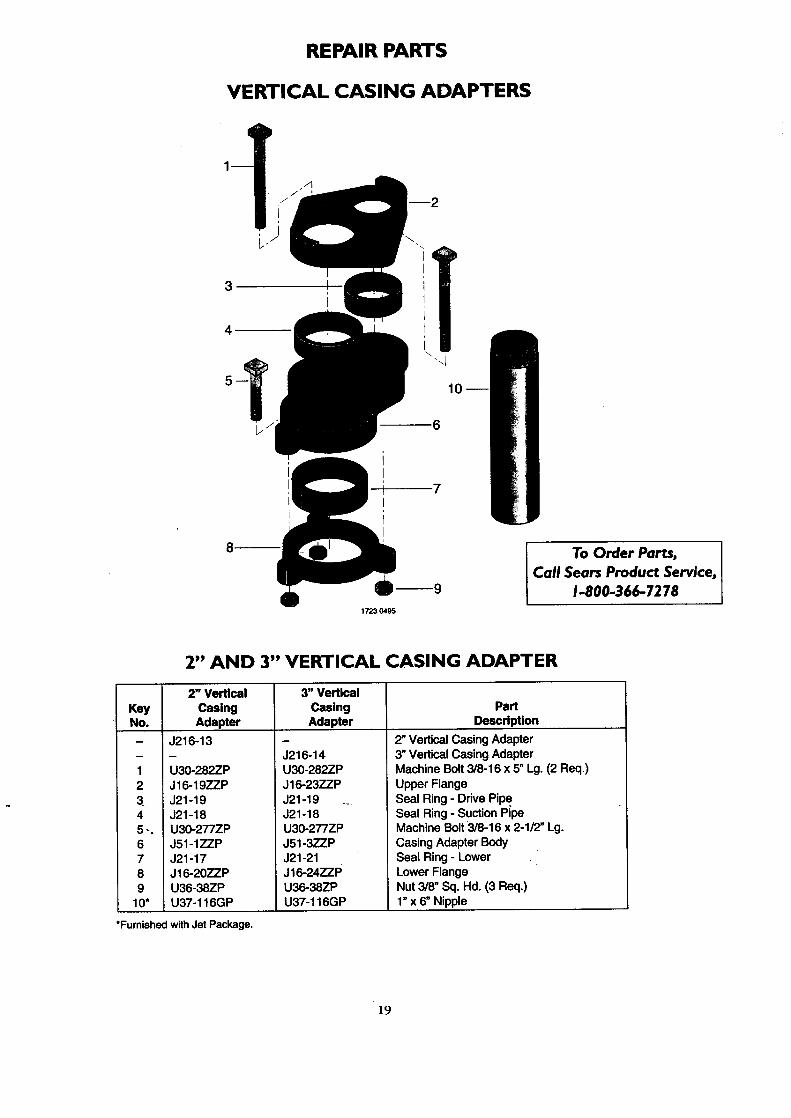
VERTICAL CASING ADAPTERS
iI
i\ .
10
6
1723 0495
To Order Parts,
Call Sears Product Service,1-800-366-7278
2" AND 3" VERTICAL CASING ADAPTER
KeyNo.
12
45_°
6789
10"
2" Vertical
CasingAdapter
J216-13
U30-282ZPJ16-19ZZPJ21-19J21-18
3" Vertical
CasingAdapter
J216-14U30-282ZPJ16-23ZZP
J21-19 ...J21-18
Part
Description
2" Vertical Casing Adapter
3" Vertical Casing AdapterMachine Bolt 3/8-16 x 5" Lg. (2 Req.)
Upper FlangeSeal Ring - Drive PipeSeal Ring - Suction Pipe
U30-277ZPJ51-1ZZPJ21-17J16-20ZZPU36-38ZPU37-116GP
U30-277ZP
J51-3ZZPJ21-21J16-24ZZP
U36-38ZPU37-116GP
Machine Bolt 3/8-16 x 2-112" Lg.
Casing Adapter Body
Seal Ring - Lower ..Lower FlangeNut 3/8" Sq. Hd. (3 Req.)1" x 6" Nipple
*Fumished with Jet Package.
]9
SEARSOWNER'SMANUAL
MODELNO.390.251182390.251 982390.252282
Themodel number of
your Deep Well Jet Pumpwill be found on the pumpbody.
When requesting serviceor ordering parts, alwaysgive the followinginformation:
• "ProductType• Model Number• Part Number ';l:i_ll;l:l:lflgl_}_• Part Description
CRAFTSMAN""HYDROGLASS ''®CONVERTIBLE DEEPWELL ,JET PUMP
Forthe repairor replacementpartsyouneedCall7am- 7 pm,7 daysa week
1-800-366-PART-(1-800-366-7278)
For in-homemajorbrandrepairserviceCall24 hoursa day,7 daysa week
1-800-4-REPAIR(1-800-473-7247)
Forthe locationof aSearsRepairServiceCenterin yourarea
Call24 hoursa day,7 daysaweek
1-800-488-1222
Forinformationonpurchasinga SearsMaintenanceAgreementorto inquire
'aboutan existingAgreementcall g am- 5 pro,Monday-Saturday
..1-800-827-6655
_ = Sears, Roebuck and Co., Hoffman Estates,-.: 60179 U.S.A.