seamless integration of injection molding and …
TRANSCRIPT

SEAMLESS INTEGRATION OF INJECTION MOLDING AND STRUCTURE ANALYSIS TOOLS
Allen Y. Peng*, Wen-Hsien Yang and David C. Hsu CoreTech System Co.,Ltd., HsinChu, Taiwan, ROC
Rong-Yeu Chang
National Tsing-Hua University, HsinChu, Taiwan, ROC
Abstract
The application of CAE analysis in injection-molded plastic part is becoming popular in the recent years, especially for part structure design and molding process optimization. Users study the designs and experiments through numerous individual CAE tools. In fact, these analyses and designs should be mutually dependent. The process-resulting properties might be not favorable to the final products, such as fiber-induced anisotropic mechanical property. Besides, the mesh requirement for different CAE analysis might be different. In this paper, an integrated approach from design phase to manufacturing phase is proposed to seamlessly combine part structure analysis and injection molding analysis through related-data linking and mesh property mapping. This developed approach is proved from numerical experiments to be a cost-effective method for related part/mold designers.
Introduction
The application of CAE analysis in injection-molded plastic part is becoming popular in the recent years, especially for part structure design and molding process optimization. Users usually study the designs and manufactures through numerous individual CAE tools. An increasing number of industrial parts are made of plastic for its low cost and superior material properties in the recent years. However, the material characteristic of plastic part is extremely dependent on molding process. The process-induced properties, such as fiber-induced anisotropic mechanical properties, might not be favorable to the structural requirement of final products. The traditional structure analysis is to perform CAE analysis based on the assumption of one or several isotropic materials. But it neglects some molding effects. Sometimes the results of analysis could be different from reality.
Injection molding simulation is capable of simulating the filling, packing, and cooling processes, as well as the part warpage after ejection. It has been widely applied in industry and earns a fine reputation. Here we integrate injection molding and structure
analysis through an interfacing program to enhance structure analysis with molding effects.
Integrated numerical analysis approach
The integrated numerical analysis approach is to link the data between commercial injection molding CAE –“Moldex3D” and other commercial structure CAE through an interfacing program, such as mesh and molding-induced material properties. Especially for fiber-reinforced plastic parts, we know the characteristics of fiber-reinforced plastic part strongly depend on the orientation patterns. The strength is stronger in the in-fiber direction and weaker in the across-fiber direction. Moldex3D has been provided the prediction of fiber orientation and orientation-induced anisotropic material. These anisotropic material properties will be automatically translated as the material properties of element in other structure CAE system through this integrated approach.
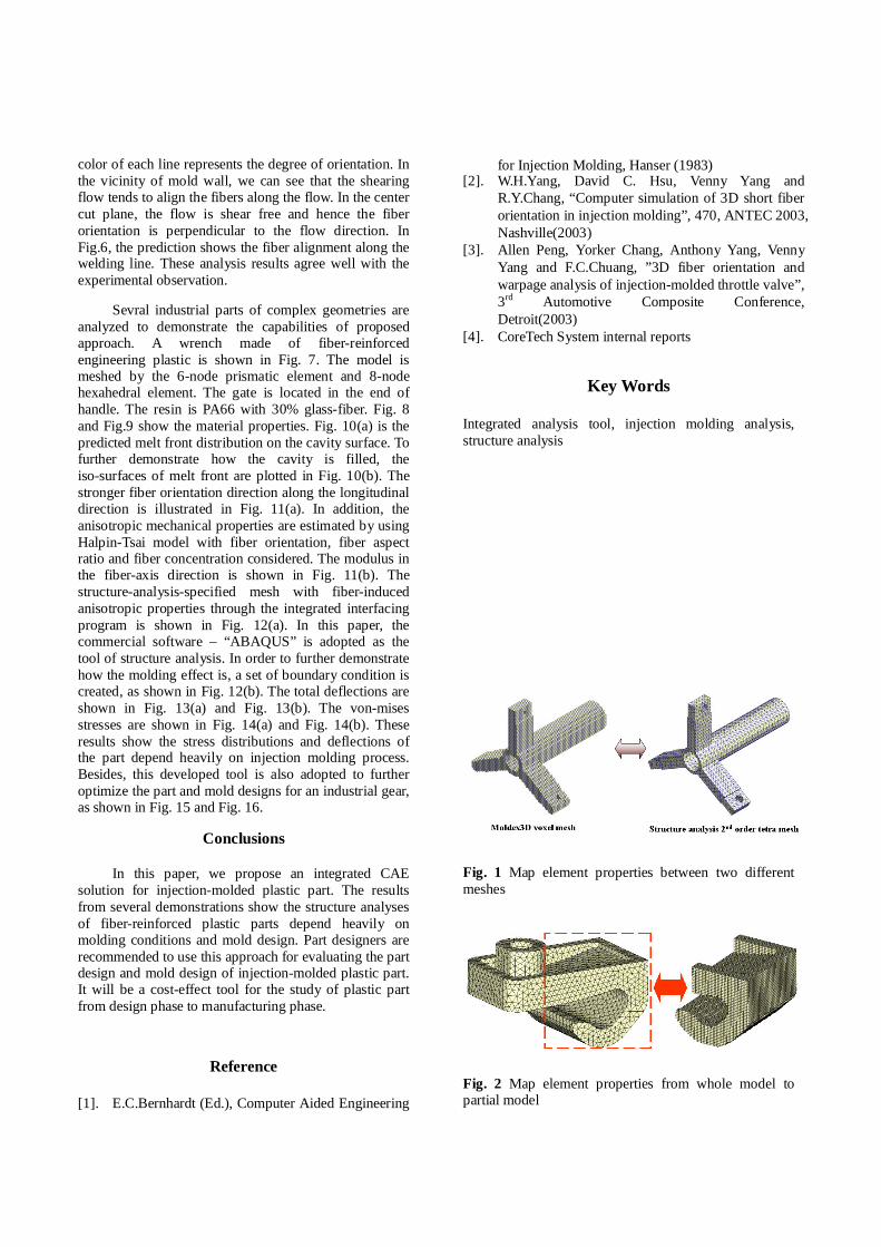
Besides, the mesh requirement might be not the same for mold-filling analysis and structure analysis. The mesh of structure analysis could be focused on the area of stress concentration. However, the mesh of mold-filling analysis is stressed on the higher element resolution across the thickness direction. This approach further provides the mapping function to map the element properties from Moldex3D-specified mesh to user-specified mesh, as shown in Fig. 1. It correctly matches the elements and maps the material properties even though the mesh characteristics are totally different. It can also map the element properties from whole model to partial model, as shown in Fig. 2. This proposed approach has been integrated successfully into Moldex3D as an analysis tool, as shown in Fig. 3.
Results and discussion
A rectangular plate of 100x50x1 mm molded with glass-fiber reinforced PET is simulated to validate the prediction of fiber orientation. Fig.4 shows the part geometry and the filling pattern. The gate is located in the center of the plate. Fig.5 displays the fiber orientation on the different cut planes. The orientation of the lines indicates the most favorable orientation direction and the
color of each line represents the degree of orientation. In the vicinity of mold wall, we can see that the shearing flow tends to align the fibers along the flow. In the center cut plane, the flow is shear free and hence the fiber orientation is perpendicular to the flow direction. In Fig.6, the prediction shows the fiber alignment along the welding line. These analysis results agree well with the experimental observation.
Sevral industrial parts of complex geometries are analyzed to demonstrate the capabilities of proposed approach. A wrench made of fiber-reinforced engineering plastic is shown in Fig. 7. The model is meshed by the 6-node prismatic element and 8-node hexahedral element. The gate is located in the end of handle. The resin is PA66 with 30% glass-fiber. Fig. 8 and Fig.9 show the material properties. Fig. 10(a) is the predicted melt front distribution on the cavity surface. To further demonstrate how the cavity is filled, the iso-surfaces of melt front are plotted in Fig. 10(b). The stronger fiber orientation direction along the longitudinal direction is illustrated in Fig. 11(a). In addition, the anisotropic mechanical properties are estimated by using Halpin-Tsai model with fiber orientation, fiber aspect ratio and fiber concentration considered. The modulus in the fiber-axis direction is shown in Fig. 11(b). The structure-analysis-specified mesh with fiber-induced anisotropic properties through the integrated interfacing program is shown in Fig. 12(a). In this paper, the commercial software – “ABAQUS” is adopted as the tool of structure analysis. In order to further demonstrate how the molding effect is, a set of boundary condition is created, as shown in Fig. 12(b). The total deflections are shown in Fig. 13(a) and Fig. 13(b). The von-mises stresses are shown in Fig. 14(a) and Fig. 14(b). These results show the stress distributions and deflections of the part depend heavily on injection molding process. Besides, this developed tool is also adopted to further optimize the part and mold designs for an industrial gear, as shown in Fig. 15 and Fig. 16.
Conclusions
In this paper, we propose an integrated CAE solution for injection-molded plastic part. The results from several demonstrations show the structure analyses of fiber-reinforced plastic parts depend heavily on molding conditions and mold design. Part designers are recommended to use this approach for evaluating the part design and mold design of injection-molded plastic part. It will be a cost-effect tool for the study of plastic part from design phase to manufacturing phase.
Reference
[1]. E.C.Bernhardt (Ed.), Computer Aided Engineering
for Injection Molding, Hanser (1983) [2]. W.H.Yang, David C. Hsu, Venny Yang and
R.Y.Chang, “Computer simulation of 3D short fiber orientation in injection molding”, 470, ANTEC 2003, Nashville(2003)
[3]. Allen Peng, Yorker Chang, Anthony Yang, Venny Yang and F.C.Chuang, ”3D fiber orientation and warpage analysis of injection-molded throttle valve”, 3rd Automotive Composite Conference, Detroit(2003)
[4]. CoreTech System internal reports
Key Words
Integrated analysis tool, injection molding analysis, structure analysis
Fig. 1 Map element properties between two different meshes
Fig. 2 Map element properties from whole model to partial model
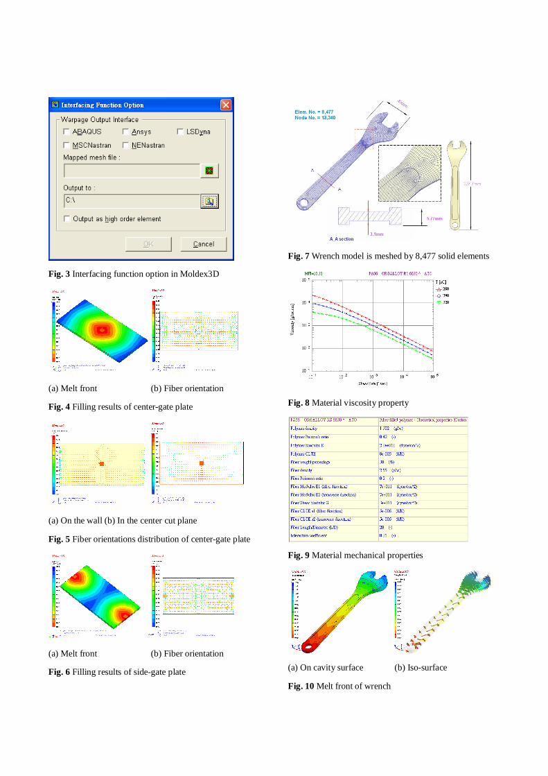
Fig. 3 Interfacing function option in Moldex3D
(a) Melt front (b) Fiber orientation
Fig. 4 Filling results of center-gate plate
(a) On the wall (b) In the center cut plane
Fig. 5 Fiber orientations distribution of center-gate plate
(a) Melt front (b) Fiber orientation
Fig. 6 Filling results of side-gate plate
Fig. 7 Wrench model is meshed by 8,477 solid elements
Fig. 8 Material viscosity property
Fig. 9 Material mechanical properties
(a) On cavity surface (b) Iso-surface
Fig. 10 Melt front of wrench

(a) Fiber orientation (b) Major modulus
Fig. 11 Fiber-induced properties of wrench
(a) Model is shown on ABAQUS/CAE
(b) Boundary conditions
Fig. 12 ABAQUS analysis conditions
(a) With orientation effect (b) Without orientation effect
Fig. 13 Deflection (scale: 5)
(a) With orientation effect (b) Without orientation effect
Fig. 14 Von-Mises stress distribution
Fig. 15 Mold-filling simulation for an industrial gear
Fig. 16 Mode analysis in ANSYS for an industrial gear