seacap 21/004 landslide management - gov.uk€¦ · · 2016-08-02seacap 21/004 landslide...
TRANSCRIPT

SEACAP 21/004 Landslide Management
Mainstreaming Slope Stability Management
Theme 8 Remedial Measures: Design 8.3 Cross Section Design
8.4 Earthworks Design (including 8.7 slope drainage)

SEACAP 21/004 Landslide Management
Theme 8 Contents
Part 1 - Slopes1) Overview of basic soil mechanics (Introduction),2) Soil Slope stability analysis (Theme 8.1).
why slopes fail, failure shapes how each is analysedUse of slope stability analysis programs. Forward and backanalysis to diagnose problems.
3) Rock Slope stability (Theme 8.2)4) Cross section design (Theme 8.3)5) Earthworks design
new cuttings and embankments (Theme 8.4) Remedial works to improve stability (Theme 8.4)
Part 2 – Retaining walls6) Overview of soil mechanics (Introduction)7) Gravity retaining wall design (Themes 8.5 and 8.6)8) Embedded retaining walls (Themes 8.5 and 8.6)9) Reinforced soil walls (Themes 8.5 and 8.6)

SEACAP 21/004 Landslide Management
This session will address the following questions:
When there are stability problems on an existing road alignment:how do you diagnose the cause using slope stability analysis and backanalysis?How do you improve the existing stability?
When designing a new road alignment:how do you minimise negative impacts on existing slopes?How do you design new earthworks (overview only)?

Theme 8.3 - Cross Section Design
The choice of cross section depends on balancing the needs to:provide a good road alignment maintaining good slope stability minimising construction costs.
SEACAP 21/004 Landslide Management

Table of advantages and disadvantages to each road cross section
SEACAP 21/004 Landslide Management

Choice of cross section to minimise soil slope instability:
1) Fill at toe to increase resisting force(FOS increases)
2) Balanced cut and fill (little difference to FOS for whole slope instability, reduced FOS for local instability)
3) Cut at crest to reduce driving force(FOS increases)
SEACAP 21/004 Landslide Management

Minimising negative impacts on sites of existing slope failures
Deep seated failure
Shallow planar failure
Unstable rock
SEACAP 21/004 Landslide Management

Only likely to be possible without instability in gentle slopes. Future instability likely unless slope remediation undertaken.
Toe erosion controlled. Temporary support likely to be needed for wall construction. Slope above road still liable to failure. Revetment or retaining structure also needed above road if slope is cut.
Anchored retaining wall expensive and requires specialist equipment. Difficult to construct on unstable slope but minimises excavation into slope and no temporary slope support needed. Good if space is tight.
SEACAP 21/004 Landslide Management
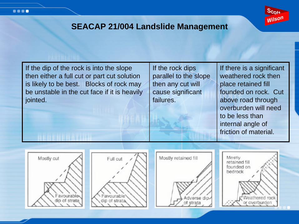
If the dip of the rock is into the slope then either a full cut or part cut solution is likely to be best. Blocks of rock may be unstable in the cut face if it is heavily jointed.
If the rock dips parallel to the slope then any cut will cause significant failures.
If there is a significant weathered rock then place retained fill founded on rock. Cut above road through overburden will need to be less than internal angle of friction of material.
SEACAP 21/004 Landslide Management

Roads in steep rock slopes
Only feasible in strong massive bedrock with planes of weakness dipping into hillside.
Very expensive may be more cost effective to divert road and provide half tunnel
Short span bridges, masonry buttresses used to cross re- entrants. Rockfalls can be a problem.
SEACAP 21/004 Landslide Management
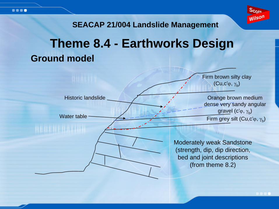
Theme 8.4 - Earthworks DesignGround model
Moderately weak Sandstone (strength, dip, dip direction, bed and joint descriptions
(from theme 8.2)
Firm brown silty clay (Cu,c’ϕ, γb )
Orange brown medium dense very sandy angular
gravel (c’ϕ, γb )Firm grey silt (Cu,c’ϕ, γb )
Historic landslide
Water table
SEACAP 21/004 Landslide Management

SEACAP 21/004 Landslide ManagementFactors of safety, governs chance of failure and likelihood of movements requiring repair.
FOS=1.1 Low to mod risk
Road is not highly usedGravel tracks which can be easily repairedRoad closure is acceptableRegular inspection, and maintenance will be implemented.Short design lifeReasonable certainty in ground model (e.g. good GI data or where backanalysis of existing slopes corresponds well with GI and observations)
FOS=1.2 Road closure will result in economic loss or risk human safetyMaintenance will not be implementedRoad surfaces are less movement tolerant.Some uncertainty in soil model (e.g. due to little GI or rapidly varying soil conditions).
FOS=1.3 Very long maintenance free design life requiredHigh speed traffic and hard road surfaces prohibit movementVery high road usage where failure results in large economic and human loss

Earthworks design - Cuttings
SEACAP 21/004 Landslide Management

SEACAP 21/004 Landslide Management
Behaviour of cuts in clays and siltsShort term Exhibit high cohesion and no/little friction
In short term, cuts in clay can stand at steep angles (60 degrees) unsupported.Max Height of cut slope is approximately H = 2Cu/γb
Consistency Undrained shear
strength Very soft < 20 kPa
Soft 20-40 kPa Firm 40 -75 kPa Stiff 75 – 150 kPa
Very Stiff 150 – 300 kPa Hard > 300 kPa
Correlation between consistency and Cu
Exudes between fingers when squeezed
Moulded with light finger contact
Moulded with firm finger pressure
Cannot be moulded, indented with thumb only
SEACAP 21/004 Landslide Management
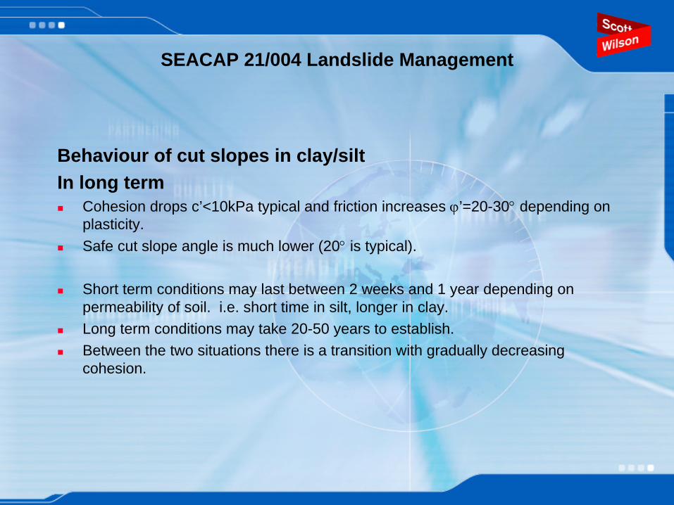
Behaviour of cut slopes in clay/siltIn long term
Cohesion drops c’<10kPa typical and friction increases ϕ’=20-30° depending on plasticity.Safe cut slope angle is much lower (20° is typical).
Short term conditions may last between 2 weeks and 1 year depending on permeability of soil. i.e. short time in silt, longer in clay.Long term conditions may take 20-50 years to establish.Between the two situations there is a transition with gradually decreasing cohesion.

SEACAP 21/004 Landslide Management
Soil type Typical slope angle
High plasticity clay
<1(V):3(H)
Low plasticity clay/silt
1(V):2.25(H) to 1(V):3(H)
Uncemented granular soils
1(V):2.25(H) to 1(V):1.5(H)
Cemented granular soils
1(V):1.5(H)
Rock slopes >1:1
Typical cut slope angles in UK where long design life for deep cuts with, FOS=1.3 no maintenance requirement.
Actual cut could be steepened for:
•Lower FOS
•Shorter design life
•Small cut heights
Shallower cut angles could be needed for:
•Steep slopes above cut
•High ground water

Cutting slope angles from ORN16
SEACAP 21/004 Landslide Management

SEACAP 21/004 Landslide Management
Cutting profiles
Single slope Multi-slope BenchedFor single strength soil Where soil strength
varies with depth. Surface water energy reduced – erosion reducedPonding on benches can lead to failureBenches catch falling debris.Debris must be cleared to avoid overloadingEasier to vegetate benches than steep slope.
weak
strong
weak
strong

SEACAP 21/004 Landslide Management
Face erosion/weathering causes:washout of uncemented granular soils, loss of cementation in cemented soils, rapid softening of clays.
Caused by:Rapid surface water flowsWater ponding on ground surfaceVegetation growth on face, burrowing and icingWater seepage from face
Face protection methods include:Drainage (will cover slope drainage in later session)Vegetation to bind surface togetherFace covering e.g. revetment.

SEACAP 21/004 Landslide Management
If a cut cannot be achieved within the space available at a sufficiently flat angle to provide the required factor of safety then slope stabilisation measures will be required.
Situations where this may be the case are:Where you are cutting into natural slopes which were already close to their limiting angle of stability before the works,Where the road must cut through the toe of an existing slipWhere failures occur during or after construction
We will cover slope stabilisation measures in the next session.

SEACAP 21/004 Landslide Management
Earthworks Design - Embankments
SEACAP 21/004 Landslide Management
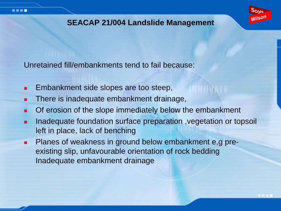
Unretained fill/embankments tend to fail because:
Embankment side slopes are too steep,There is inadequate embankment drainage, Of erosion of the slope immediately below the embankmentInadequate foundation surface preparation ,vegetation or topsoilleft in place, lack of benchingPlanes of weakness in ground below embankment e,g pre-existing slip, unfavourable orientation of rock bedding Inadequate embankment drainage

SEACAP 21/004 Landslide Management
Typical embankment side slopes – After excavation, transport and compaction fills retain little cohesion. Side slopes dictated by friction.
Fill type Typical Friction angle
Side slope angle for FOS=1.1
Side slope angle for FOS=1.2
Clay – High plasticity 20-25° 18-23° 17-21°
Clay/Silt – Low plasticity 25-30° 23-27° 21-25°
Sand 30-35° 27-32° 25-30°
Gravel 35-40° 32-37° 30-35°
Rough guide to side slope angles for well compacted fill embankments with good drainage and where founding soils are better or the same as the embankment fill.

SEACAP 21/004 Landslide Management
Compaction –Usually compact in layers using compaction plant which achieves 95% proctor compaction. Hand compaction using hand rammers may only achieve 80%. Can cause settlement and damage to road therefore where possible leave for one wet season before releveling the surface and laying hard top.
Sheeps foot roller used for compacting clay fills.

SEACAP 21/004 Landslide Management
Benching –Very important to avoid weak plane at contact between embankment and underlying soil.Benches slope away from slope to avoid water ponding and softening of soilHeight of bench dictated by soil type and bench width governed by compaction plant and slope angle.
Example benching detail.
Source “Standard Network Rail Details”

SEACAP 21/004 Landslide Management
Embankments founded on clayIn the short term
Clay exhibits high cohesion (Cu) but little or no friction (ϕu =0). In other words adding weight to the soil does not improve the strength. (τ
= Cu + σv ’ tan ϕu, but ϕu =0 so τ
= Cu)
In the long termClay exhibits low cohesion (c’=0-10kPa typically) and higher friction (ϕ’=20 to 30°
typically). The soil strength is enhanced by the weight of the overlying embankment.
When designing embankments on clay soils, we analyse both short and long term but short term usually governs stability.

SEACAP 21/004 Landslide Management
8.4 Earthworks Design - Slope remediation
Probleme.g. existing slip or
unacceptably low FOS
Can the problem be avoided?E.g. by altering road alignment,
Bridging.
Yes, do cost vsbenefit study
No
Can driving forces be reduced?
E.g. material removal, bridging,
No
Can soil shear resistance be improved?
e.g. drainage, piles, anchors, reinforcement,
chemical treatment
No
Can the resisting soil weight be increased ?
e.g. toe loading or erosion protection
Yes, do cost vsbenefit study
Yes, do cost vsbenefit study

Reduce driving forces by removing material
SEACAP 21/004 Landslide Management
Stabilisation of a slide in the Colorado River Valley
Source “Landslides – Analysis and Control” Transportation Research Board National
Academy of Sciences

Reduce driving forces by use of light weight fillThis only applies where the driving forces are provided by new road embankment.
Light weight fill materials include:Pulverized Fuel Ash – PFA – unit weight 15kN/m3
Encapsulated sawdust and wood fibre – Above water table asphalt used to delay decaying process.Polystyrene – unit weight =7kN/m3
Light weight aggregate – unit weight may be as low as 4kN/m3
Tyre bailsSeashells
SEACAP 21/004 Landslide Management

Improve soil shear resistance by slope drainage
Two main functions:
1) A method of increasing resisting forces by improving shear resistance
or
2) A method of reducing erosion from surface water
SEACAP 21/004 Landslide Management

An overview of the different methods of ground water control
Horizontal or vertical drains
SEACAP 21/004 Landslide Management

• Run along crest of slope on across slope above line of slope failure - Used to intercept surface water.
• Regular inspection and maintenance necessary. Blockage or damage can lead to water being diverted into the slope causing new instability.
• End of drainage run must link into properly designed gulley to carry water down slope and into streamway at base.
Cut off drain
SEACAP 21/004 Landslide Management

• Used to collect surface runoff and near surface ground water.
• Often no more than about 1m deep trench lined with filter fabric and polythene sheet on downslope face then filled with coarse gravel fill and flexible perforated pipe where high flows are expected.
• Care to avoid instability during construction.
• Drain must be connected into properly designed toe drain or streamway.
Herringbone drains
SEACAP 21/004 Landslide Management

Counterfort Drains
• used to depress a high water –table. • Run directly down slope and dug to a depth of 3m or more at 3-10 m centres. Trench lined with filter fabric and filled with coarse gravel and flexible perforated pipe where high flows are expected.•Reduce risk of slope instability due to orientation.
•Drain must be connected into properly designed toe drain or streamway.
SEACAP 21/004 Landslide Management

Example of counterfort drains to stabilise cutting flanks
C6
Old counterfort drains
uncovered during
excavation works at toe of cutting (drains are about 2m
deep, 0.5m wide and 6m centres)
SEACAP 21/004 Landslide Management

Horizontal drains
•Used to relieve pore pressures at depth.
•Specialist equipment neede to drill hole and install perforated plastic pipe wrapped in filter fabric. Often fan of drains installed at 5 degrees upwards.
•Expensive to install
•Success relies on intercepting high permeabiltiy subsoil or seepage paths within subsoil.
SEACAP 21/004 Landslide Management
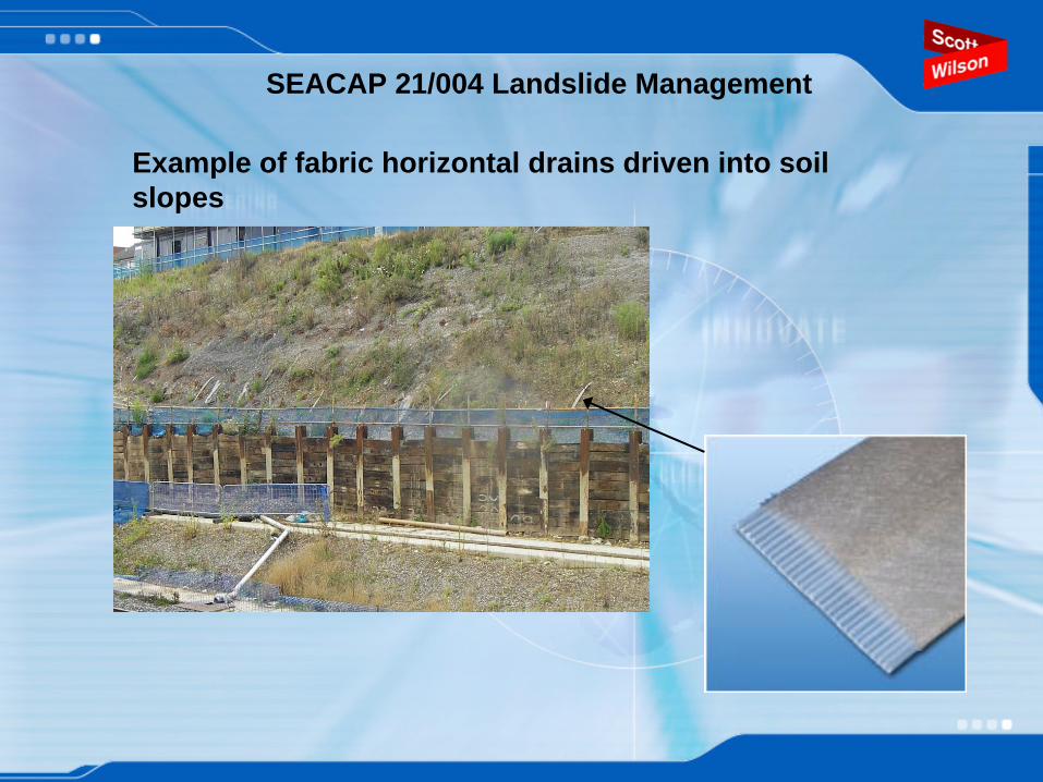
Example of fabric horizontal drains driven into soil slopes
SEACAP 21/004 Landslide Management
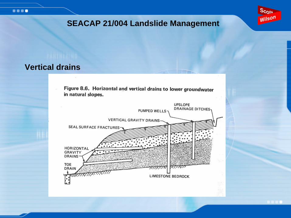
Vertical drains
SEACAP 21/004 Landslide Management

Improve resisting forces using piles or anchors
SEACAP 21/004 Landslide Management

Dead man anchorsGet resistance from bearing of plate within ground.
Picture taken from Platipus website
SEACAP 21/004 Landslide Management

Grouted Anchor
Gets resistance
from friction over grouted
length behind slip
surface
SEACAP 21/004 Landslide Management
Figure from BS8081

Increase shear resistance with reinforcement.
Two commonly used reinforcement types:1) Geogrid or metal strips laid into newly constructed fill.2) Soil nails installed in existing slopes
SEACAP 21/004 Landslide Management

Geogrid reinforcement
SEACAP 21/004 Landslide Management
Pictures taken from Tensar brochure.

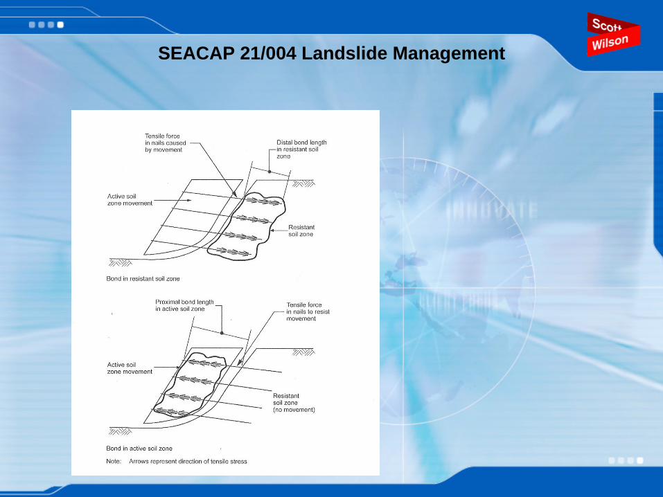
Soil nails
SEACAP 21/004 Landslide Management

Facings – soft facings for shallow slopes
Combined erosion protection and light face restraint mesh facing for
soil nailed slope.
Geogrid wrapped around soil bags to provide temporary facing until
vegetation takes hold.Photos from CIRIA C637 and Tensar website
SEACAP 21/004 Landslide Management

Harder facings for steeper slopes
Geogrid connected to gabion facing
Steel facing provides both formwork and structural facing. Lined with geotextile to retain
soil until vegetation gets established.
SEACAP 21/004 Landslide Management
Photos taken from Tensar Brochure
SEACAP 21/004 Landslide Management

Increasing soil resistance by chemical treatmentAgain there are many different forms of chemical treatment. Two of most common are mixing soil with lime or cement.Chemical is added in situ using an auger to create columns or layers of increased strength.Lime increases strength and stiffness of high plasticity clayCement works in either clay or sand.Expensive and required specialist equipment and careful site control.
SEACAP 21/004 Landslide Management

Increase the resisting forces by toe loading.
This can be achieved by forming an embankment at the toe of the problem slip.If space is limited then a retaining wall may be needed to hold the added fill in place.
SEACAP 21/004 Landslide Management

In this session we have looked at:
1) How do you design cross sections to minimise negative impact on slope stability.
2) What do you need to consider when constructing new cut or embankments
3) When you have diagnosed a problem, the process that you go through to determine the best solution.
4) Some of the many slope remediation methods available.
SEACAP 21/004 Landslide Management