sea air gap agent - dtic.mil sea air gap agent (saga) was created ... a coast watch dash 8 maritime...
TRANSCRIPT
DEFENCE SCIENCES TECHNOLOGY
Sea Air Gap Agent
David Clark
DSTO-TR-1304
20020828 099

*
Ä DEFENCE SCIENCE* TECHNOLOGY
Sea Air Gap Agent
David Clark
Surveillance Systems Division Electronics and Surveillance Research Laboratory
DSTO-TR-1304
ABSTRACT
This document describes the implementation of intelligent agents in a distributed surveillance simulation exercise. Agent Oriented Systems provided the agent framework known as JACK. The synthetic environment includes STAGE, which provides the physical domain simulation, the DSTO DICE simulation software, which is designed to provide command and control representation and an in-house developed prototype planning function for optimisation of surveillance plans.
RELEASE LIMITATION
Approved for public release
/p fo2-fl- M^

Published by
DSTO Electronics and Surveillance Research Laboratory PO Box 1500 Edinburgh South Australia 5111 Australia
Telephone: (08) 8259 5555 Fax: (08)8259 6567
© Commonwealth of Australia 2002 AR-012-311 April 2002
APPROVED FOR PUBLIC RELEASE

Sea Air Gap Agent
Executive Summary
Surveillance Systems Modelling and Assessment (SSMA) group of Surveillance Systems Division (SSD) aims to provide modelling and simulation capabilities. One aspect of the capability is the use of Intelligent Agents (IA) to carry out simulation of military systems and processes. Examples include operator performance or a commander's decision making process, which may need to be incorporated into simulations designed to assess surveillance capability. Simple intelligent agent behaviour may be addressed using scripting languages. However, a more robust capability is provided by adding an agent framework to the basic simulation environment.
The purpose of this report was to describe the use of IA technology in a simulated environment to control surveillance assets. The implementation was carried out using the Agent Orientated Software JACK agent development suite. This required bringing together a distributed application using two computers and several available simulation frameworks, including:
• The Scenario Toolkit and Generation Environment, STAGE - providing the physical domain simulation for the scenario,
• The Distributed Interactive C3 Effectiveness simulation, DICE - provides the command & control representation which includes the message handling function between STAGE, and
• The JACK Intelligent Agents.
Two JACK agents, a "Planning controller" and a "platform controller" were developed and used within the agent infrastructure. A previously developed "surveillance asset planning tool" was also used in the simulation. It provided a planning function by generating optimised surveillance plans.
In operation, a human player initiates the JACK Agent by sending a message indicating the start of a new surveillance planning process. The IA obtains current surveillance asset position information from the STAGE physical domain simulation. This is then passed to the surveillance-planning tool, which determines a new plan for maximum coverage. The IA passes the plan in the form of new waypoints back to the surveillance assets.
The exercise demonstrates the use of IA technology in a synthetic environment and also the use of contracted support in development of such systems for defence projects.

Authors
David Clark Surveillance Systems Division
David Clark completed his B.Sc. in Computer and Information Science from the University of South Australia in 2001. He is currently part of the analysis team in Surveillance Systems Modelling and Assessment group contributing to both the IT and the analysis aspects. For the four previous years David's work focussed on providing computing support for the Integrated Surveillance Assessment Tool and the Virtual Air Environment. Prior to 1997 David was involved in several areas of surveillance research. These included carrying outfield trials, collecting data to assess the capability of commercial satellites to detect small maritime vessels' wakes (project Blue Groper) and the use of the Midcourse Space Experiment (MSX) satellite to detect aircraft.

DSTO-TR-1304
Contents
GLOSSARY
1. INTRODUCTION 1
2. SEA AIR GAP AGENT 1 2.1 AADS Scenario 1 2.2 JACK 1 2.3 Planning Function 2 2.4 DICE 2 2.5 STAGE 2
3. SAGA OPERATION 3 3.1 Hardware 3 3.2 Software Distribution 3 3.3 Running SAGA 3
4. RESULTS 3
5. RECOMMENDATIONS AND OVERVIEW OF WHAT IS NEEDED TO ENABLE THE USE OF IA IN SIMULATION 8
6. ACKNOWLEDGEMENTS 9
7. REFERENCES 10
APPENDIX A: SAGA FUNCTIONAL SPECIFICATION NOTES 11 A.l. Introduction 12
A.l.l A JACK planning agent 12 A.1.2 JACK platform agents 12
A.2. The Planning Agent / Planning Capability Interface 13 A.3. The STAGE / DICE Interface 14 A.4. System Architecture 16 A.5. Agent Structure 17 A.6. Startup 18 A.7. Configuration 19
A.7.1 DICE 19 A.7.2 SAGA 19
A.8. Appendix A 21
APPENDIX B: PLANNING FUNCTION INPUT/OUTPUT SPECIFICATION 24 B.l. Overview 24 B.2. Operational Issues 24 B.3. Role of the Planning Tool in the theoretical Scenario 24 B.4. Planning Function Inputs 25 B.5. Planning Function Outputs 26

DSTO-TR-1304
APPENDIX C: AADS SCENARIO DESCRIPTION 27 C.l. The AADS Scenario 27 C.2. The AADS Synthetic Environment 28
C.2.1 Objectives 28 C.2.2 Models and Agents 29 C.2.3 The AADS SE 31
APPENDIX D: STEP-BY-STEP GUIDE TO RUNNING SAGA 32 D.I. SGI Work Station 32 D.2. Personal Computer 32

DSTO-TR-1304
Glossary AADS
ADFORM
AEW
AEW&C
AOS
AVT
BCSS
C2
C3
CAP
CE
COTS
CSS
DACAO
DICE
DICEFORM
DO
DSS
DSTO
GBR
GUI
HP
IA
ITD
JAL
JNI
JÖRN
JOSEF
LAN
LLAD
M&S
OPFOR
OPSO
ORBAT
PDS
PN
Australian Air Defence System
Australian Defence Formatted Message
Airborne Early Warning
Airborne Early Warning & Control
Agent Orientated Systems
Asset Visualisation Tool
Battlefield Command Support System
Command & Control
Command Control Communication
Combat Air Patrol
Control Element
Commercial Off The Shelf
Command Support System
Decision Aids for Controlling Air Operations
Distributed Interactive C3 Effectiveness
DICE Formatted Message
Director of Operations
Decision Support System
Defence Science & Technology Organisation
Ground Based Radar
Graphical User Interface
Human Player
Intelligent Agent
Information Technology Division
JACK Agent Language
Java Native Interface
Jindalee Over the Horizon Radar Network
Joint Synthetic Environment Facility
Local Area Network
Low Level Air Defence
Modelling & Simulation
Opposing Force
Operations Officer
Order of Battle
Phoenix Display System
Petri Nets

DSTO-TR-1304 PUI Peripheral Interface Unit
RAAF Royal Australian Air Force
RAP Recognised Air Picture
RCC Regional Correlation Centre
SAGA Sea Air Gap Agent
SE Synthetic Environment
SGI Silicon Graphics Incorporated
SQN Squadron
SSA Systems Simulation & Assessment
SSD Surveillance Systems Division
SSMA Surveillance Systems Modelling & Assessment
STAGE Scenario Toolkit and Generation Environment
UAV Unmanned Aerial Vehicle
VAE Virtual Air Environment

DSTO-TR-1304
1. Introduction
As part of the Virtual Air Environment (VAE) task AIR 99/187, Surveillance Systems Modelling and Assessment (SSMA) group of Surveillance Systems Division (SSD) aims to provide modelling and simulation environments. One aspect of the Synthetic Environment (SE) is the use of artificial Intelligent Agents (IA) to carry out some or all of the command and control.
Carrying out an Integrated Surveillance experiment using an IA paradigm to control surveillance assets provides an initial platform for further work in this area. This report describes the development of agents and implementation of a software agent infrastructure to carry out such an experiment.
2. Sea Air Gap Agent
Sea Air Gap Agent (SAGA) was created using the Agent Orientated Systems (AOS) JACK agent development kit by taking advantage of existing arrangements between DSTO and AOS. The main software components are JACK, Distributed Interactive C3 Effectiveness (DICE) simulation, Scenario Toolkit And Generation Environment (STAGE), Planning Function and the Australian Air Defence System (AADS) scenario. A description of each of the components is provided in the following sub sections. A Human Player (HP) within the DICE environment adds additional control; this is discussed in section 3.
2.1 AADS Scenario
The physical environment implemented using STAGE has been provided by making use of the existing AADS scenario developed by Systems Simulation and Assessment (SSA) group of Information Technology Division (ITD). Additional surveillance platforms have been added to the scenario, which are under direct control of the JACK agent. They consist of airborne platforms representing a RAAF P3C maritime patrol aircraft, a Coast Watch Dash 8 maritime patrol aircraft and a Global Hawk Unmanned Aerial Vehicle (UAV).
A detailed description of the AADS scenario can be found in Appendix C.
2.2 JACK
JACK is a Commercial Off The Shelf (COTS) agent development tool kit developed by AOS. In the SAGA project two JACK agents, a "Planning controller" and a "platform controller" were developed using the agent infrastructure and executed within the DICE environment. The role of the JACK agents is to control the location of the surveillance assets. Current position information of each of the surveillance assets is obtained and passed as input to the Planning Function, refer 2.3. An optimisation of the sensor mix based on a surveillance requirement is then carried out. The resulting plan of waypoints is sent to the JACK agent, which then issues position updates to the surveillance assets
A detailed Functional Specification by AOS covering the JACK development work can be found in Appendix A.

DSTO-TR-1304
2.3 Planning Function
The Planning Function is an in-house tool developed by SSMA group of SSD. Implementation in the SAGA project as been limited to meet specification and ease of integration. Basically the surveillance requirement is fixed whereas ideally this would be provided as input to the tool based on the required surveillance coverage. Input is the current position of surveillance assets and output is a new set of waypoints based on a fixed surveillance requirement. Activation of the planning function is by direct request from the HP via the controlling JACK agent.
A detailed specification describing the planning function can be found in Appendix B.
2.4 DICE
The DICE simulation has a general-purpose capability for the modelling of C2 systems. DICE provides a flexible GUI driven architecture to facilitate communication between components in the simulation. These components include artificial agents, human participants (optional) and interfaces to physical domain models and Command Support System (CSS) [1]. Artificial agents might represent the behaviour or functionality of individuals or groups of, commanders in the C2 system, and can utilise a range of intelligent agent techniques. The human player facility allows a real commander to interact with other agencies present in the C2 system.
Within this synthetic environment DICE provided the interface to JACK agents, the STAGE simulation and a human player. The DICE scenario specifies the major components and the message passing requirements. The human player facility within DICE was utilised to represent the analyst who provides the control for initiating the Planning Function.
A detailed document describing the STAGE Peripheral Unit Interface (PUI) by Aspect Computing can be found in [2].
2.5 STAGE
STAGE provides the simulation engine and the physical environment with a 2D visual display showing a map covering the region of interest and icons representing the participating assets. The STAGE scenario is as used by the AADS with three surveillance assets added. The important points are that STAGE provides entity state information with current position being of prime importance. Updated waypoints of the three surveillance assets are provided back to STAGE upon completion of the Planning Function. STAGE then sets a new course for the assets complying with the updated waypoints.
A detailed description of the AADS scenario can be found in Appendix C. Documentation describing the STAGE Peripheral Unit Interface (PUI) by Aspect Computing can be found in [2].

DSTO-TR-1304
3. SAGA Operation
SAGA operates within a framework comprising of the software components described in section 2 and the hardware as discussed below. A Human Player (HP) acts as one component of the control loop by initiating the agent to commence a planning cycle. Feedback is provided within the various windows and dialogs of the software components. A complete discussion of the operations is detailed in the following sub- sections.
3.1 Hardware
Hardware comprises of the following components;
• Personal Computer: Pentium 3 550 MHz Personal Computer with 19" monitor and accelerated graphics capability. Windows NT 4 SP5 OS.
• SGI Work Station: Octane Workstation with 21" wide screen format monitor and accelerated graphics capability. IRIX 6.5.11 OS.
• SSD Classified LAN providing socket connection
3.2 Software Distribution
• DICE, JACK and the Planning Function reside on the Personal Computer.
• STAGE and the AADS scenario reside on the SGI Work Station.
3.3 Running SAGA
The HP is required to initialise two software components, namely DICE and STAGE. There is no strict order as to which program is started first. DICE is used to initialise the remaining software components
After initialisation, the HP interacting with DICE starts the SAGA simulation running. After an arbitrary period of time the HP initialises the planning of assets to meet a new surveillance requirement by issuing a DICEFORM message (formatted message standard of which a subset is Australian Defence Formatted Message, ADFORM) to the agent. The agent interacts with the Planning Function controlling the input of surveillance asset current positions and then forwarding the new plan to update asset waypoints in STAGE. This process can be repeated as required. A step-by-step guide to setting up and running SAGA is provided in Appendix D.
4. Results
There are two main objectives of this report:
• Firstly to show the use of an IA technology in a simulated environment.
• Secondly to demonstrate the use a COTS product and contracted support in development of such systems for defence projects.

DSTO-TR-1304
The first objective was successfully achieved using the AOS JACK Agent Language (JAL) to provide an IA to control surveillance assets within STAGE. Figures 1 and 2 show the main display windows for DICE and STAGE respectively at the start of the simulation. The HP initiates the IA by issuing a formatted message as shown in figure 3. This can be carried out at any time during the simulation period. The sequence of events carried out by the IA is most obvious at completion of the planning cycle. At this point the surveillance assets DASH8, P3C001 and GH001, change course as illustrated in figure 4. Also a command window provides some feedback from the JACK agents, see figure 5 and 6. The whole exercise is fully demonstrable by following the procedures provided in Appendix D.
The second objective was achieved by contracting personnel from AOS to carry out the IA development work and integration into the scenario. This was achieved successfully, with AOS showing a thorough understanding of the requirements and following through with best practice software design and methodology. A component of this is the SAGA Functional Specification Notes that can be viewed in Appendix A.
0le E*t_¥>ew Management ^raw_ Execution belp_
l-iqix|
Mods: DICEAPP "3 Applicator):
7 ;
Jl i —-—' i : ■
~.' / / i ■ '
/' ,-~ ' ! I
I I _..«'
-J
■-HP-'
-J "i<'i r- ~. .,- . - STAGE w
'/ /
U J--Z2
SAGA
7/
jä Ready •NUMj
Figure 1: DICE main window showing main simulation players

DSTO-TR-1304
.IT, x*-3ty*>HjMi ■■•"^~^
■g. SfAGEDulrtiuse-hSlror ttmrnt database jeseftitxs
.File Ecil SAD Scripts Runtime Maps Options
SiSI*i J> \j fj 3nj W| ■ £j
Ove/vtew
'3EV.-»V^iB5-;;.|§| ... ... . . , .... ,., .. I Runtime Mo ->
¥rrffime "pÜöiliS ÜsarTime SÖftDiagäV'
Platforms
LCLAEWOOliO ICI.AB,VQQ2:1 tCL;fl=W300:Z iCL:C«_DA3M3_001: iCL;Cutifi:4 LCL:[.Vc5HB:S LCLDarwin:6 tCLFFGCDi:? l£L:GBRD(H«' lCL;GeRO02S LCUGBROD3:10 LOLGßR0ü4tl
:Weapons
L38&!
mMsM ^Qigß^swij
SK&3 ra«s^
kÖ.Wfl
avis
<Jh&ftjfe&&@.
'■-'■.]■A"--' :"■■•£%& ■■-■'■ '■--■'•".■'■.,:' J-. •■■'•-,-■■■, r'üiii- ..^*. -•--.--•."'..■ '.-■■;'.•>"■'■■'.;". j.'t.
mj
■STS-
«1 - jfliigöL
HI ■
Figure 2: STAGE Situation Awareness Display at start of simulation

DSTO-TR-1304
?C DICEFORM Editor
Ble View Help
na D-BADIO
©■ MSGID
Information | DICEFORM j Set | Fields |
Abbreviation
Description
Figure 3: DICEFORM Editor window showing selection of message to initiate JACK IA
'^^Sf^P^iti^'^ttiM.. !'0m^:däiä>ai»'1o^.'^' ma File Eeit SAD Scripts Runtime Mops OP1,0"5
_-J 3J^!±J id.!!Ml S; .li Mlä ji!
lido
Rurorrie Info J !
SlmTIme ]5MM3
:: UserTime JÖÖ3Z33
; Plat'orms
LCUAH?,V031:0 '..CL-J&MlXc-.l
LCL:<\BV31D:?
LCL-CV^_DASH3_0Ol LCLCuilny!
LCI 1MSHB;S LCLD«wln:E
LCL'PFGCOl:?
L.::i.:GBR(JliT:li
LCUQBROOZe
ItCLiCBROOaiO JLCUGBR0Ü411
Weapons
Ctvls
Figure 4: STAGE Situation Awareness Display showing surveillance assets change in course

DSTO-TR-1304
3 R \trlkl ? 1 \hin\mvn nxR
[Uses JACK Intelligent Agents BDI Extension. Copyright 2000. AOS] JMatLink: thread is running ======= Initialisation for PlatformController(ralph@7„portal) DICE hoot = quake DICE port = 555G Connecting ;ssd. init . StringbJrapper@9f 585c4b ssd. init .Stringldrapper@980c5c4b ssd. init. Stringldrapper@94d45c4b ---------- Initialisation for PlatforinController(DASH3@7,portal) identity = DASH8 name = DASH8 assetld = 1 planner - ralph ======= Initialisation for PlatformController(P3C001 @7.portal) identity = P3C001 name = P3C001 assetld -2 planner - ralph ======= Initialisation for PiatformControll er(GH001@%portal) identity = GH001 name = GH001 assetld = 3 planner = ralph
Figure 5: Command window showing initialisation of JACK IA
3 e:\idk1 2.1\bin\iuva cxc
plan 0: 3.3.G. [-13.0421 8578338G23.132.12535095214344.0.0.0] [-11.735699653625488.132.2559051513672.0.0.0] [-10.165363311767578.133.1492156982422.0.0.0] [-9.75922679901123.127.82403905029297.0.0,0] [-13.3794527053833.121.88111877441406.0.0.0] [-16.16415023803711 .124.8690185546875.0.0.0]
sending to GH001Hlportal plan 1: 2.3.6.
[-14.190849304199219.130.71348571777344.0.0.0] [-13.481399536132812.130.12100219726562.0.0.0] [-12.866787910461426.132.81906127929688.0.0.0] [-10.35947036743164.128.3166046142573.0.0.0] [-11.76464557647705.125.78837585449219.0.0.0] [-14.224719047546387.130.74G32263183594.0.0.0]
sending to P3C001@%portal plan 2:1.3.6.
[-16.16415023803711.124.93468475341797.0.0.0] [-14.677599906921387.124.19029993779297.0.0.0] [-14.419960975646973.122.35122680664062.0.0.0] [-13.04218578338623.127.20024108886719.0.0.0] [-11.22854232788086.129.1702880359375.0.0.0] [-13.075891494750977.132.12535095214844.0.0.0]
sending to DASH8@7-portal MonitorTrackHoue plan initiated MonitorTrackMoue plan initiated MonitorTrackMoue plan initiated
Figure 6: Command window showing feedback from JACK IA after completion of the planning cycle
DSTO-TR-1304
5. Recommendations and Overview of What is Needed to Enable the Use of IA in Simulation
The AOS COTS product JACK is a development environment for IA. JACK agents are written using the JACK Agent Language (JAL) and a set of Java classes which provide basic agent functionality. JAL is implemented as an extension to Java - a JACK application is compiled to Java code and can therefore run in any environment that supports Java. JACK is designed to be an open system, so wrappers for agents written in other languages or systems (such as C, C++, Petri Net, or CLIPS) are straightforward to construct. JACK agents can also be readily interfaced to a variety of software products (such as databases) and bespoke applications. Specific support is provided within JACK (Views and JACOB) to assist in both these tasks.
JACK is neutral with respect to simulation type - it provides support for both event- stepped and time stepped agent-based simulations. When interfacing JACK agents with an existing simulation package, one can do this directly via a custom JACK / simulation package interface or use an existing infrastructure such as DICE. In the case of STAGE, given that STAGE / DICE and JACK / DICE interfaces are already available, interfacing JACK to STAGE via DICE was the obvious way to proceed. Note that simulation environments such as STAGE have a limited scripting capability for specifying entity behaviour. Agents provide a convenient mechanism for providing simulation entities with much richer behaviours and they also facilitate the integration of these entities into larger experimental environments.
It is recommended that further work be done to provide a range of agents suitable for use in Modelling & Simulation (M&S) of surveillance systems. Developing both in-house and consultant experience in wrapping modular available agents in a variety of codes would be a worthwhile objective. The current leading technology provided by AOS has ensured a considerable degree of conformity in M&S areas across DSTO. This will facilitate the exchange of agents.
There is therefore further scope in the development of IA for use in simulated environments. This is especially true for analysis work where speed of computing is of the utmost importance. It is envisaged that agents could act to automate many of the decision-making processes required during Monte Carlo type simulations to allow speedy iteration of scenarios in generating the required statistics for analysis in Operations Research.

DSTO-TR-1304
6. Acknowledgements
The Sea Air Gap Agent was developed by building on a number of existing capabilities. The author gratefully acknowledges the following for their contribution.
1. Agent Orientated Software for implementation of the JACK agents and preparation of the SAGA functional specification provided in Appendix A.
2. Mr Victor Fok for supplying the Planning Tool function and preparation of the functional specification provided in Appendix B.
3. Systems Simulation and Assessment group of Information Technology Division for supplying and setting up the AADS scenario and associated software applications, and for providing the overview documentation shown in Appendix C.

DSTO-TR-1304
7. References
8. Gabrisch,C; Bowden,F.DJ.; Davies,M.; Haydon,N.; WinklesJ. (1999) "Synthetic Environment Support to Air Visualisation Tool Development", Proc. SimTecT1999, Melbourne, Australia, 29 Mar - 1 Apr, pp 281-288
9. STAGE PUI System Design Document for DSTO-D04, Aspect Computing Pty. Ltd., October 2000.
10

DSTO-TR1304
Appendix A: SAGA Functional Specification Notes
Purchase Order 492393/1
SAGA: Functional Specification Notes
June 2001
Prepared for: Dr. Paul Berry DSTO/SSD Salisbury
Prepared by: Agent Oriented Software Pty. Ltd.
11

DSTO-TR-1304
A.l. Introduction
The intent of the SAGA project is to deliver infrastructure to support the further development of agent applications within SSD. The infrastructure will be based on STAGE and DICE. The initial demonstrator is to consist of
A.l.l A JACK planning agent.
The planning capability will be provided by SSD as a Matlab program, which can be executed by the JACK agent via Java Native Interface (JNI). The data required for planning execution will be provided by a number of platform agents. The output of planning execution will be a single plan, which specifies a revised waypoint list for each platform.
A.1.2 JACK platform agents.
These agents will monitor entities in STAGE and provide position data to the planning agent on request. It is not the intent of this project to provide an exhaustive set of platform agents, nor agents with all desired functionality. When the current waypoint is modified (either by the planning agent or by the platform reaching it) the platform sends the new waypoint to its corresponding entity in STAGE.
12

DSTO-TR1304
A.2. The Planning Agent / Planning Capability Interface
The planning capability expects to be passed an array of type AssetState (one entry for each platform). It returns an array of type AssetPlan. The Java side data declarations are as follows:
public class WayPoint implements Java.io.Serializable {
public double latitude; public double longitude;
public double altitude; public long time;
}
public class AssetState implements Java.io.Serializable { public int assetld; public int assetType; public float currentLatitude; public float currentLongitude; public float currentAltitude; public int currentWaypoint; public int nWaypoints; public WayPoint[] waypoints; public boolean planningRequired; public int startTime;
}
public class AssetPlan implements Java.io.Serializable { public int assetld; public int currentWaypoint; public int nWaypoints; public WayPoint[] waypoints;
}
13

DSTO-TR-1304
A.3. The STAGE / DICE Interface
The existing interface supports
• reporting of entity positions (red, blue, neutral) • reporting of entity detections • reporting of selected entity attributes (eg fuel, damage) • control of moving airborne entities via
o teleport (go directly to lat, Ion) o headings (head to lat, Ion) o bearings
It does not support
• dynamic waypoint list modification • reporting / control of sensor parameters
Reporting can be either on request or provided on a regular basis. Regular reporting can not be restricted to particular entities - it applies to all entities. (Note that in the demonstrator, we will only be concerned with regular reporting). Reports contain platform (aka entity) identification in the form of a callsign, which can then be used by a dispatcher to route the report to the appropriate platform agent.
DICE delivers messages as DICEFORMS. In this case, the JACK platform agents will receive position information embedded in a D-ENTITY-POSITION message and send revised waypoint information to STAGE also in the form of a D-ENTITY-POSITION message. The actual content of the DICEFORMs arriving at and departing from JACK PUI is user configurable, and is summarised below. More detail regarding this configuration process can be found in [2]. Note that the communication protocol is asynchronous - no acknowledgements are involved.
Table A-l: Position Report Message from STAGE
Name DICEFORM Data Types
Notes
ADFORM Name D-TXT100 D-ENTITY-MESSAGE
Originator D-TXT100 STAGE ENTITY Id D-INTEGER Entity id ENTITY Callsign D-TXT100 Entity name ENTITY Location D-LATLONGD Entity location ENTITY Bearing D-REAL Entity bearing in degrees ENTITY Altitude D-REAL Entity altitude in meters
Date-Time D-INTEGER Time of report
14

DSTO-TR1304
Table A-2: Waypoint Update Message to STAGE
Mapping Name
ADFORM Name Originator ENTITY Id ENTITY Callsign EntityLocation
DICEFORM Data Types
D-TXT100 D-TXT100 D-INTEGER D-TXT100 D-LATLONGD | Entity location
Notes
D-ENTITY-POSITION SAGA Entity id Entity name
15

DSTO-TR-1304
A.4. System Architecture
The overall system architecture is shown in Figure A-l. Note that planning is initiated through the Human Player agent - the user sends an empty D-RADIO message to the JACK agent.
MATLAB Planner
o
Figure A-1: System Architecture.
16

DSTO-TR1304
A.5. Agent Structure
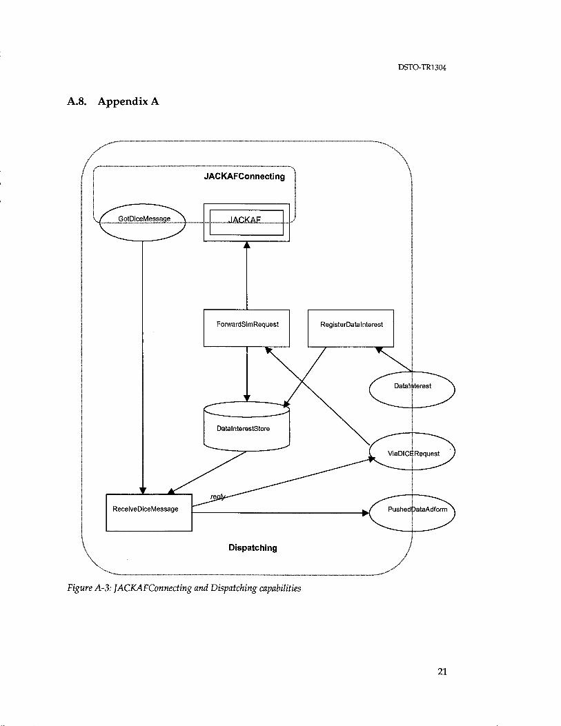
We have two JACK agents, a PlanningController agent and Platf ormController agent. These agents in turn have the following capabilities:
Agent Capability Description PlanningController JACKAFConnecting manage JACK / DICE interface
Dispatching send incoming DICE messages to the appropriate agent
ControlPlanning perform the replanning function PlanEvaluating choose the best plan
PlatformController PlatformDataForming record platform location TaskPlanTracking track progress towards the
current waypoint
The behaviour of the JACK agents is specified in A.8.
17

DSTO-TR-1304
A.6. Startup
The JACK agents are created by the loader (in jacksim. jar) from data specifed in scenario.def.
The startup event flow is summarised below:
STAGE/DICE
started
Started PUI at host:port
connect
Loader
started
PlannlngController
created
tialised
tialised
Scenario definition
PlatformConlroller
created ►i^r
STAGE/DICE
Figure A-2: Startup Event Floiv.
JACK
18

DSTO-TR1304
A.7. Configuration
A.7.1 DICE
No user configuration of DICE is required for running the STAGE scenario developed for the project.
A.7.2 SAGA
The agent details are specified in the scenario file e:\Software\Saga\saga_scenario.def. The current scenario involves a PlanningController agent (ralph) and three PlatformController agents (DASH8, P3C001 and GH001). The file is reproduced below; use it as a template to create modified scenarios.
/ ** * This file defines the setup of a scenario using the standard SSD
SAGA * scenario definitions. */
<Include :file "e:\\Software\\Saga\\ssd\\init\\standard.def"
> // Define and initialise a PlanningController
<PlanningControllerInit :name "ralph" :agents (
< StringWrapper rvalue "DASH8" > < StringWrapper :value "P3C001" > < StringWrapper :value "GH001" >
) >
// Define and initialise sensor platforms
<PlatformControllerInit :name "DASH8" :identity "DASH8" :assetld 1 :planner "ralph"
> <PlatformControllerInit
:name "P3C001" :identity "P3C001" :assetld 2 :planner "ralph"
>
19

DSTO-TR-1304
<PlatformControllerInit :name "GH001" :identity "GHOOl" :assetld 3 :planner "ralph"
20
DSTO-TR1304
A.8. Appendix A
ReceiveDiceMessage
Dispatching
Figure A-3: JACKAFConnecting and Dispatching capabilities
21

DSTO-TR-1304
PlatformDataForming
PreparePlatformData
TrackData
initialised
TaskPlanTracking
PlatformDefinition
MonitorTrackMove
Figure A-4: PlatformDataForming and TaskPlanTracking capabilities
22

DSTO-TR1304
PjatformAgentl nfo
ControlPlanning
Planning Function
ReplanProcedure
SelectPlan
PickSomePlan
PlanEvaluating
Figure A-5: ControlPlanning and PlanEvaluating capabilities
23

DSTO-TR-1304
Appendix B: Planning Function Input/Output Specification
B.l. Overview
• SSD will provide the planning tool capability as a Matlab function via a Java-to- Matlab interface toolkit (JMatLink). The interface provides ease of data transfer between Java and a Matlab engine within which the function runs.
• AOS will be provided with all the necessary Java code to setup the interface for passing/receiving data structures between their Java-based Jack intelligent agent framework and the Planning function as specified in the initial design specifications.
B.2. Operational Issues
Because the planning function can take a very long and unknown amount of time to compute the best plan solution, it is assumed that all other processes will be paused until the Matlab function returns results, before proceeding. This is to ensure that by the time the plans are computed, they are still relevant.
B.3. Role of the Planning Tool in the theoretical Scenario
The proposed scenario will be tightly related to the phase 1 capability of the planning tool function (phase 1 is focused on static targets only). An area of approximately 900km by 1500km located on the northern coast of Australia is assumed for the scenario. The surveillance assets available will be aircrafts such as P3Cs, UAVs and Dash8s. Information about the capabilities of the surveillance assets (eg speed, sensor range, pre-defined fixed set of possible routes, etc) is assumed to be stored in the planning function already.
The aim of this scenario is to coordinate the use of surveillance assets to detect an unknown number of static or slow moving surface vessels in the specified area. The key indications of effectiveness will be the minimisations in coverage overlaps by various surveillance assets and the time to complete the full surveillance coverage requirements. Information such as detections of targets by assets' sensors will not be utilised in this planning tool function, as targets are assumed independent.
The start of the scenario will see a number of assets already deployed and following a defined path. At a certain time after the start, the planning tool function is called and all information about asset's current plans and status information will be passed. The Matlab planning function will then open up a simple GUI that allows the surveillance requirement to be specified interactively. Assuming all processes are paused until the function returns results, the Matlab planning function will run until it has found a near optimal solution. The results consist of plans for every asset. Each plan covers the full history and future waypoints for an asset. These results will be sent back to the
24

DSTO-TR1304
planning tool Java wrapper, which will then pass the information to the agents requiring the results.
The planning function can be called at any time during the scenario execution. This can be a system call or an initiation by the user. Whilst the planning function runs, no further planning calls will be accepted, until the current one finishes. Currently, the planning function outputs a single near-optimal set of plans for every asset. However, future capability might see the need to output many plausible options and information about the performance tradeoffs.
B.4. Planning Function Inputs
The planning function receives a single data structure consisting of a variable sized array of asset objects. Each asset object consists of various asset specific information such as current location, list of waypoints, sensor details, and other status information. The structures specifications in Java are defined below:
class Waypoint {
float latitude; float longitude; float altitude; long speed;
}
class AssetState {
int assetld; int assetType; float currentLatitude; float currentLongitude; float currentAltitude; int currentWaypoint; int nWaypoints; Waypoint[] waypoints; boolean planningReguired; int startTime;
}
The waypoints array structure allows us to define a waypoint together with the associated transit speed.
The Asset structure contains all the essential information needed by the planning tool function. An important field in the structure is the 'planningRequired' Boolean flag which indicates whether the asset will participate in the route re-planning process. The startTime field, tells the planning tool function when to consider the asset for planning purposes.
The waypoint list structure is assumed to consist of the full set of past, present and future waypoints for the asset. This is required since the planning tool assumes no memory of where the asset has been in the past.
25

DSTO-TR-1304
B.5. Planning Function Outputs
The output of the planning function will consist of a variable sized array of individual asset's planned route. Only those assets whose 'planningRequired' flag was set to true in the planning input, will be included in the asset array.
It is assumed that the plans will be passed on to a tasking agent or an asset agent which manages the assets adherence to the waypoints.
The waypoint list structure is assumed to consist of the full set of past, present and future waypoints for the asset. The future waypoints may be altered by each execution of the planning tool.
public class AssetPlan {
int assetld; int currentWaypoint; int nWaypoints; Waypoint[] waypoints;
}
26

DSTO-TR1304
Appendix C: AADS Scenario Description
C.l. The AADS Scenario
The "interactive" AADS scenario deals with a Redland air and ground offensive and Blueland's defensive response. This scenario focuses on defining an Order of Battle (ORBAT) and setting an initial posture from which free play will occur.
Redland (a fictitious island to the north of Australia) has two available airfields at KAM and MAK. Redland has four F15 and four F16 at KAM, and eight F15 and one Airborne Early Warning (AEW) aircraft at MAK. There are air traffic control/air defence radars at KAM and MAK and two air defence radars at other locations on the main Redland island.
Darwin and Tindal are the available airfields for Blueland. The Blueland air ORBAT has six FA18 at Darwin, and six FA18 and one AEW aircraft at Tindal. There are air traffic control/air defence radars at Darwin and Tindal and air defence radars at Port Keats, Bathurst Island and Gove.
Figure 1 shows the air scenario unfolding from a Red perspective. A Redland Airborne Early Warning & Control (AEW&C) and fighter escorts are positioned just south of the main Redland island. The Redland air strike plan involves four fighters that are sent to the east of Darwin as a feint. The real air strike package takes a western route to Tindal. This package comprises four F15 escorts and four F16 in the ground attack role. The Blueland scenario is entirely interactive, so no more information will be provided at this point.
27

DSTO-TR-1304
Figure C-l: A graphic of the air component of the interactive AADS scenario.
The interactive AADS scenario also has a land element in the vicinity of Tindal. Blueland defence consists of machine gunners surrounding the high value areas. An armoured vehicle also patrols outside this inner defence. Blueland Low Level Air Defence (LLAD) fire units also surround the high value area.
C.2. The AADS Synthetic Environment
C.2.1 Objectives
One of the key roles of the interactive AADS synthetic environment is to provide an immersive environment for the planners and decision makers within the AADS (in particular the Director of Operations (DO) and Operations Officer (OPSO)). This immersive environment contains a combination of real, virtual and constructive elements interacting in a seamless fashion.
An immersive synthetic environment for the OPSO could be used for training purposes as well as for demonstration, trialing, and evaluation of prototype C2
28

DSTO-TR1304
technologies alongside operational Command Support System (CSS). The OPSO participant would interact with the Simulation Environment (SE) via the C2 technologies (CSS, Decision Support System (DSS) and communications capabilities) available in the operational environment in addition to the prototype CSS. The Asset Visualisation Tool (AVT) is an example prototype CSS for the OPSO, additional tools will be developed under ITD's Decision Aids for Controlling Air Operations (DACAO) task. In the operational environment the OPSO uses the Phoenix Display System (PDS) to provide the Recognised Air Picture (RAP).
C.2.2 Models and Agents
The interactive SE developed as part of this research activity will provide an environment for an OPSO (the human player/participant) to undertake air asset and battlespace management training and to evaluate prototype CSS. With this objective in mind a focus is to develop artificial agents for organisations and staff which interact with the OPSO. The level of fidelity of each of these artificial agents depends on the significance of the influence on and interaction with the OPSO and is assessed on a case by case basis. In designing this environment it is useful to firstly consider the roles of the OPSO and subordinate staff.
The OPSO has a prime responsibility for optimal management of the assets and resources available for conducting air defence operations under guidance of the DO. In summary the OPSO roles and responsibilities include maintaining situation awareness, managing alert states, scrambling of aircraft, deployment of Combat Air Patrol (CAP), and allocation of intercepts. In addition to these overarching functions the OPSO needs to be aware of fuel and weapon loads, aircraft utilisation rates (for maintenance), and aircrew duty limits as part of the overall scheduling of assets and resources.
Key C2 system agencies (organisations and staff) that interact with the OPSO are the DO, control element (CE), and the squadrons (SQN). The OPSO also receives an updated air picture from the Regional Correlation Centre (RCC) via the PDS. Therefore, in the AADS SE the key C2 agencies required are OPSO, DO, CE, SQN, and RCC, key C2 technologies required are AVT and PDS, and there must be a communications/messaging facility for the OPSO participant.
The AADS SE is implemented in the Joint Synthetic Environment Facility (JOSEF) using the DICE software. Artificial agents for key C2 agencies were developed using Petri net (ALPHA/Sim) and intelligent agent technologies (JACK and ATTITUDE), interfaces between the required C2 technologies (PDS and AVT) and DICE were reused from previous developments, and an internal messaging facility is provided by DICE.
The physical environment surrounding the C2 system is represented using the STAGE software. STAGE provides the physical battlefield simulation that represents the movement and characteristics of friendly and enemy air assets. STAGE also represents sensors, for example Ground Based Radar (GBR), the Jindalee Over the Horizon Radar Network (JÖRN) and Airborne Early Warning & Control (AEW&C) aircraft.
Petri Nets (PN) have been used to develop the RCC, DO, and SQN artificial agents. A CE artificial agent was developed using the JACK intelligent agent software and a Petri
29

DSTO-TR-1304
net tool. The ATTITUDE intelligent agent software was used to develop a Pilot agent that has additional functionality to the CE.
The following simple sequence of events is used to describe the functions/behaviour of the various AADS artificial agents and physical domain models: • The RCC agent collates detections which it receives from many sensors (eg the JÖRN and GBR sensors in the STAGE physical domain model) and maintains the RAP. It forwards current and new tracks to the PDS and to the CE.
• In response to a new enemy track appearing in the PDS the OPSO participant may undertake an action to intercept the enemy aircraft track. Firstly the OPSO may need to request and receive approval from higher command (the DO agent in this case). Having obtained approval, the OPSO tasks an intercept mission. This is achieved by the OPSO tasking the relevant SQN to place a fighter aircraft on an intercept mission. The OPSO then tasks the CE to control a specified fighter aircraft on intercept. The OPSO may then need to readjust the posture of the other air assets, for example if the fighter aircraft selected for the intercept mission were re-tasked from an existing CAP mission then the OPSO may choose to replenish the CAP by scrambling new aircraft from the SQN.
• Currently, the DO agent accepts requests for intercept from the OPSO, then approves them after a prescribed short delay.
• There is a SQN agent for each aircraft type at each airbase. A SQN agent keeps track of the status (fuel, weapons, mission etc) of each aircraft as it is reported by STAGE, and reports this status to the AVT. Such statuses may be requested or actual. The SQN agent is also responsible for scrambling aircraft, CAP, and adjusting the alert states as tasked by the OPSO.
• It is the responsibility of the CE agent to direct allocated fighter aircraft to the intercept location/aircraft. The CE agent maintains a database of current intercepts and forwards the most recent target position (as observed in the PDS/RAP) to the relevant aircraft. The JACK version of the CE handles multiple intercepts on a single target, and initiates intercepts earlier than the PN version of the CE (which waits for the next update from RCC). Currently, neither the PN nor JACK CE agent receives feedback if/when an own force aircraft intercepts and kills an Opposing Force (OPFOR) aircraft or if an own force aircraft is shot down.
• The Pilot agent handles the behaviour for all pilots and extends the CE functionality. The Pilot agent includes organic sensor detections of the fighter aircraft in addition to the RAP during an intercept mission. The Pilot agent receives feedback if/when an own force aircraft intercepts and kills an OPFOR aircraft or if an own force aircraft is shot down. After the engagement the Pilot agent instructs any remaining aircraft under its control to return to base (note that the engagement occurs according to the weapon specifications as described in the physical domain model). In addition to the air C2 system there is also a land C2 system and environment. This
has been accomplished to date by inclusion of a simple ground-based air defence capability at the Tindal air base and Redland ground offensive operations in the Tindal region. The ground based air defence and offence may influence the number of aircraft or taxiways and runways available as the SE is executed. The AADS SE has been developed to support a land commander human player who would use the Battlefield
30

DSTO-TR1304
Command Support System (BCSS) C2 technology to provide them with a Land picture and to influence the land battle as required. Currently the land battle is scripted and automated within STAGE but a human player could actively influence the land component during the simulation.
C.2.3 The AADS SE
The artificial agents, models and C2 technologies that constitute the AADS SE can be seen in Figure 2 which shows a snapshot of the DICE simulation scenario development screen for this SE.
^SIAGE JACK AVT HSBl £ite Edit View Management Draw Execution Help
Mode DICEAPP yj Application: j Scenario Development H|
EXTERNAL
RCC PHOENIX
n Ready
Figure C-2: A snapshot of the DICE simulation screen for the interactive AADS SE.
31

DSTO-TR-1304
Appendix D: Step-by-Step Guide to Running SAGA
D.I. SGI Work Station
1. Once logged on open a terminal window.
2. Change to the STAGE DICE directory: cd /usr/vpi/stage3.1/user_ssa
3. Source the configuration information by typing: source setup
4. Run the STAGE DICE simulation engine by typing: stage-dice
5. Accept the question dialogue box by clicking on OK
6. Stage is now ready for participation in the exercise.
D.2. Personal Computer
1. Login to the PC
2. From the Start menu select Programs>DICE Simulation Software Suite>Startup Server
3. The Server will open in a window that can be minimised.
4. From the Start menu select Programs>DICE Simulation Software Suite>DICE
5. Once the main DICE as opened go to the File menu and select Open
6. From the open dialogue box select SAGA10 then press OK
7. The SAGA10 scenario is opened showing the participating players.
8. From the Application drop down list select the option Simulation Execution
9. From the Execution menu option select Start Simulation
10. A Simulation Execution window will open. On the left is a list of the participating players, HP, SAGA and STAGE all showing a status of Not Running.
11. Click on the Prepare button. Several windows will open. These can be minimised leaving the Simulation Execution window active. Upon successful completion of this stage, the status of the participating players will change to Connected. Ready to initialise
12. Click on the Initialise button. The status of the players will change to Initialisation started... that will further change to Initialised. Ready to start when completed. During initialisation the STAGE player may fail to initialise. This is shown by the status of the STAGE player changing to Disconnected from CMA server. If this happens click on the Kill button and close all the windows that were opened when the Prepare button was pressed. Now try again from step 11.
32

DSTO-TR1304
13. Once all players are initialised go to the SGI workstation computer and click on the OK button of the Warning dialogue box that is complaining about missing bitmap files. The STAGE Database Editor window might obscure this dialogue box.
14. Change back to the PC. Click on the Start button in the Simulation Execution window. The Status of all the players will now change to Running. If this fails to happen then click on Kill and close all the windows that were opened when the Prepare button was pressed. Now start over again from step 11.
15. With the simulation running a DICEFORM message can be sent to the JACK agent that will initiate a planning cycle and send revised waypoint information to STAGE through a D-ENTITY-POSITION message.
16. Make the HP - Human Player window active. This window is one of several that are created when the Prepare button is clicked in the Simulation Execution window.
17. Click on the SendMessage button. A DICEFORM Editor window will open.
18. In the DICEFORM Editor window make sure the Information tab is selected. Select the drop down list of the Abbreviation field and scroll down and select the D-RADIO message.
19. Select Exit from the File menu of the DICEFORM Editor window. Click on yes to the Prompt asking if you want to send the message.
20. An Enter Message Information window will open. Select SAGA from the Destination list then click Send. Click on OK of the dialogue box that appears indicating success.
21. A Matlab Figure window will appear giving a diagrammatic representation of the Planning Tool. This may stay open for a few minutes as new waypoint positions are calculated for the participating surveillance assets.
22. Upon completion of the planning cycle the JACK agent sends the new waypoints to STAGE. This is visually shown by a change in heading of the surveillance aircraft (DASH8, P3C_001 and UAV_GH_001) in the STAGE 2D Map window of the Database Editor. This is most obvious after the first planning cycle. Subsequent planning cycles may not vary the waypoint list by any significant amount.
23. Clicking on the Stop button in the Simulation Execution window pauses the exercise. Clicking on the Kill button will stop and reset the exercise. Normal shutdown procedures are followed for closing applications and logging out of the computers.
33
DISTRIBUTION LIST
Sea Air Gap Agent
David Clark
AUSTRALIA
DEFENCE ORGANISATION
S&T Program Chief Defence Scientist FAS Science Policy \ shared copy AS Science Corporate Management Director General Science Policy Development Counsellor Defence Science, London (Doc Data Sheet) Counsellor Defence Science, Washington (Doc Data Sheet) Scientific Adviser Joint Navy Scientific Adviser (Doc Data Sheet and distribution list only) Scientific Adviser - Army (Doc Data Sheet and distribution list only) Air Force Scientific Adviser Director Trials
Aeronautical and Maritime Research Laboratory Director
Electronics and Surveillance Research Laboratory Chief of Surveillance Systems Division Division Chief of Information Technology Division Chief of Land Operations Division Research Leader Wide Area Surveillance Head SSMA David Clark Carsten Gabrisch Victor Fok
DSTO Library Library Edinburgh (2 copies) Australian Archives US Defense Technical Information Center, 2 copies UK Defence Research Information Centre, 2 copies Canada Defence Scientific Information Service, 1 copy NZ Defence Information Centre, 1 copy
Capability Systems Staff Director General Maritime Development (Doc Data Sheet only) Director General Aerospace Development (Doc Data Sheet only)

Knowledge Staff Director General Command, Control, Communications and Computers (DGC4)
(Doc Data Sheet only) Director General Intelligence, Surveillance, Reconnaissance and Electronic
Warfare
Navy SO (SCIENCE), COMAUSNAVSURFGRP, BLD 95, Garden Island, Locked Bag
12, PYRMONT NSW 2009 (Doc Data Sheet and distribution list only)
Army SO (Science), Deployable Joint Force Headquarters (DJFHQ) (L), MILPO Gallipoli
Barracks, Enoggera QLD 4052 (Doc Data Sheet only) ABCA National Standardisation Officer ( 4 copies)
Intelligence Program DGSTA Defence Intelligence Organisation Manager, Information Centre, Defence Intelligence Organisation
Corporate Support Program Library Manager, DLS-Canberra Ms Sam Doran, Defence Library Service - Sydney West
OTHER ORGANISATIONS Agent Orientated Software Pty. Ltd. - Dennis Jarvis National Library of Australia NASA (Canberra) Auslnfo State Library of South Australia
UNIVERSITIES AND COLLEGES Australian Defence Force Academy
Library Head of Aerospace and Mechanical Engineering
Serials Section (M list), Deakin University Library, Geelong, 3217 Hargrave Library, Monash University (Doc Data Sheet only) Librarian, Flinders University
OUTSIDE AUSTRALIA
ABSTRACTING AND INFORMATION ORGANISATIONS Library, Chemical Abstracts Reference Service Engineering Societies Library, US Materials Information, Cambridge Scientific Abstracts, US Documents Librarian, The Center for Research Libraries, US
INFORMATION EXCHANGE AGREEMENT PARTNERS Acquisitions Unit, Science Reference and Information Service, UK Library - Exchange Desk, National Institute of Standards and Technology, US
SPARES (5 copies)
Total number of copies: 49
Page classification: UNCLASSIFIED
DEFENCE SCIENCE AND TECHNOLOGY ORGANISATION DOCUMENT CONTROL DATA 1. PRIVACY MARKING/CAVEAT (OF
DOCUMENT)
2. TITLE
Sea Air Gap Agent
3. SECURITY CLASSIFICATION (FOR UNCLASSIFIED REPORTS THAT ARE LIMITED RELEASE USE (L) NEXT TO DOCUMENT CLASSIFICATION)
Document Title Abstract
(U) (U) (U)
4. AUTHOR(S)
David Clark
5. CORPORATE AUTHOR
Electronics and Surveillance Research Laboratory POBox 1500 Edinburgh South Australia 5111 Australia
6a. DSTO NUMBER DSTO-TR-1304
6b. AR NUMBER AR-012-311
6c. TYPE OF REPORT Technical Report
7. DOCUMENT DATE April, 2002
8. FILE NUMBER 9. TASK NUMBER 99/005
10. TASK SPONSOR DG/ISREW
11. NO. OF PACES 49
12. NO. OF REFERENCES 2
13. URL on the World Wide
http://www.dsto.defence.gov.au/corporate/reports/DSTO-TR-1304.pdf
14. RELEASE AUTHORITY
Chief, Surveillance Systems Division
15. SECONDARY RELEASE STATEMENT OF THIS DOCUMENT
Approved for public release
OVERSEAS ENQUIRIES OUTSIDE STATED LIMITATIONS SHOULD BE REFERRED THROUGH DOCUMENT EXCHANGE, PO BOX 1501), EDINBURGH, SA 5111 16. DELIBERATE ANNOUNCEMENT
No Limitations
17. CITATION IN OTHER DOCUMENTS Yes 18. DEFTEST DESCRIPTORS
Simulation, Decision making, Surveillance, Intelligent agents (computer software)
19. ABSTRACT
This document describes the implementation of intelligent agents in a distributed surveillance simulation exercise. Agent Oriented Systems provided the agent framework known as JACK. The synthetic environment includes STAGE, which provides the physical domain simulation, the DSTO DICE simulation software, which is designed to provide command and control representation and an in-house developed prototype planning function for optimisation of surveillance plans.
Page classification: UNCLASSIFIED

m o x z o >
"0 o
Q CO
3U I
CO O
>
■ O
IO CO
P
> "0 31
IO o o IO
DEFENCE SCIENCES TECHNOLOGY
ELECTRONICS AND SURVEILLANCE RESEARCH LABORATORY PO BOX 1500 EDINBURGH SOUTH AUSTRALIA, 5111
AUSTRALIA, TELEPHONE (08) 8259 5555