se700/se500: server unit /390 - fujitsu technology...
TRANSCRIPT

Edition June 2015
© S
iem
ens
Nix
dorf
Info
rma
tions
syst
em
e A
G 1
995
P
fad:
P:\
FT
S-B
S\S
erv
er\S
E-S
erv
er\S
E-D
oku\
130
390
7_B
A_S
U_3
90\p
rod
_e\b
a_su
390
.vor
English
SE700 / SE500 Server Unit /390
FUJITSU Server BS2000
Operating Manual
Comments… Suggestions… Corrections…The User Documentation Department would like to know your opinion on this manual. Your feedback helps us to optimize our documentation to suit your individual needs.
Feel free to send us your comments by e-mail to: [email protected]
Certified documentation according to DIN EN ISO 9001:2008To ensure a consistently high quality standard anduser-friendliness, this documentation was created tomeet the regulations of a quality management system which complies with the requirements of the standardDIN EN ISO 9001:2008.
cognitas. Gesellschaft für Technik-Dokumentation mbHwww.cognitas.de
Copyright and Trademarks
This manual is printed on paper treated with chlorine-free bleach.
Copyright © 2015 Fujitsu Technology Solutions GmbH.
All rights reserved.Delivery subject to availability; right of technical modifications reserved.
All hardware and software names used are trademarks of their respective manufacturers.
The Xen® mark is a trademark of Citrix Systems, Inc., which manages the mark on behalf of the Xen open source community. The Xen® mark is registered with the U.S. Patent and Trademark Office, and may also be registered in other countries.
Novell and SUSE are registered brands of Novell, Inc. in the USA and other countries.
Linux is a registered brand of Linus Torvalds.
Windows® is a registered trademark of Microsoft Corporation.
The Linux-based basic software M2000, X2000, and HNC which is installed on the Management Unit, Server Unit x86, and HNC contains Open Source Software. The licenses for this can be found in the LICENSES directory on the relevant installation DVD

U41859-J-Z126-1-76
Dok
usch
abl
onen
19x
24 V
ers
ion
7.4
de f
ür F
ram
eM
aker
V7.
xvo
m 0
9.0
2.20
10©
cog
nita
s G
mb
H 2
001
-20
102
5. J
uni
201
5 S
tand
15
:31.
15P
fad
: P:\F
TS
-BS
\Ser
ver\
SE
-Ser
ver\
SE
-Dok
u\13
039
07_B
A_S
U_3
90\
prod
_e\
ba_s
u39
0.iv
z
Contents
1 Introduction . . . . . . . . . . . . . . . . . . . . . . . . . . . . . . . . . . . . . . . 5
2 Server Unit SU700 . . . . . . . . . . . . . . . . . . . . . . . . . . . . . . . . . . . . 7
2.1 CPU box . . . . . . . . . . . . . . . . . . . . . . . . . . . . . . . . . . . . . . . . . 8
2.2 Channel box (CHE box) . . . . . . . . . . . . . . . . . . . . . . . . . . . . . . . . . 8
3 Server Unit SU500 . . . . . . . . . . . . . . . . . . . . . . . . . . . . . . . . . . . . 9
3.1 CPU box . . . . . . . . . . . . . . . . . . . . . . . . . . . . . . . . . . . . . . . . 10
3.2 Channel box (CHE box) . . . . . . . . . . . . . . . . . . . . . . . . . . . . . . . . 10
4 Operating the service processor . . . . . . . . . . . . . . . . . . . . . . . . . . . 11
4.1 Opening the SVP console . . . . . . . . . . . . . . . . . . . . . . . . . . . . . . 12
4.2 General SVP frame structure . . . . . . . . . . . . . . . . . . . . . . . . . . . . . 144.2.1 System status messages in line 22 . . . . . . . . . . . . . . . . . . . . . . . . . . 154.2.2 System status messages in line 23 . . . . . . . . . . . . . . . . . . . . . . . . . . 164.2.3 Hardware status display in line 24 . . . . . . . . . . . . . . . . . . . . . . . . . . . 174.2.4 Status displays in line 25 . . . . . . . . . . . . . . . . . . . . . . . . . . . . . . . . 18
4.3 Using SVP frames . . . . . . . . . . . . . . . . . . . . . . . . . . . . . . . . . . . 194.3.1 SVP functions (function keys) . . . . . . . . . . . . . . . . . . . . . . . . . . . . . 194.3.2 Switching between SVP frames . . . . . . . . . . . . . . . . . . . . . . . . . . . . 224.3.3 Options for switching between frames . . . . . . . . . . . . . . . . . . . . . . . . . 23
4.4 SVP frames and subframes . . . . . . . . . . . . . . . . . . . . . . . . . . . . . 244.4.1 (ML) MODE SELECTION FRAME . . . . . . . . . . . . . . . . . . . . . . . . . . . 244.4.2 (LD) PROGRAM LOAD FRAME: BASIC . . . . . . . . . . . . . . . . . . . . . . . . 274.4.2.1 (LD) PROGRAM LOAD FRAME: DETAIL-1 . . . . . . . . . . . . . . . . . . . . 28

Contents
U41859-J-Z126-1-76
4.4.2.2 (LD) PROGRAM LOAD FRAME: DETAIL-2 . . . . . . . . . . . . . . . . . . . . 324.4.3 (ST) STATUS DISPLAY FRAME . . . . . . . . . . . . . . . . . . . . . . . . . . . . 344.4.4 (MA) MANUAL OPERATION FRAME . . . . . . . . . . . . . . . . . . . . . . . . . . 354.4.5 (AD) ALTER/DISPLAY FRAME . . . . . . . . . . . . . . . . . . . . . . . . . . . . . 374.4.6 (ME) MESSAGE FRAME . . . . . . . . . . . . . . . . . . . . . . . . . . . . . . . . 414.4.7 (CH) CH/SUBCH STATUS DISPLAY FRAME: CHANNEL . . . . . . . . . . . . . . . 424.4.8 (AU) AUXILIARY FRAME: MENU . . . . . . . . . . . . . . . . . . . . . . . . . . . . 444.4.8.1 (AU1) AUXILIARY FRAME: REAL CLOCK . . . . . . . . . . . . . . . . . . . . . 454.4.8.2 (AU2) AUXILIARY FRAME: IORSF CONTROL . . . . . . . . . . . . . . . . . . 464.4.8.3 (AU3) AUXILIARY FRAME: RELATED SCB’S . . . . . . . . . . . . . . . . . . . 484.4.8.4 (AU4) AUXILIARY FRAME: POWER STAND-BY/IMPL . . . . . . . . . . . . . . 494.4.8.5 (AU5) AUXILIARY FRAME: LOAD PRESET1 . . . . . . . . . . . . . . . . . . . 504.4.9 (MF) MSF FRAME . . . . . . . . . . . . . . . . . . . . . . . . . . . . . . . . . . . 534.4.10 (PA) PERFORMANCE ANALYZER FRAME . . . . . . . . . . . . . . . . . . . . . . 54
4.5 Examples of SVP operation . . . . . . . . . . . . . . . . . . . . . . . . . . . . . . 554.5.1 Selecting IORSF . . . . . . . . . . . . . . . . . . . . . . . . . . . . . . . . . . . . 554.5.2 Activating IORSF . . . . . . . . . . . . . . . . . . . . . . . . . . . . . . . . . . . . 584.5.3 Setting up PROGRAM LOAD FRAME PRESET1 . . . . . . . . . . . . . . . . . . . 594.5.4 Setting up PROGRAM LOAD FRAME PRESET2 . . . . . . . . . . . . . . . . . . . 614.5.5 Executing IPL in PROGRAM LOAD FRAME: DETAIL-1 . . . . . . . . . . . . . . . . 624.5.6 Setting operating mode via PROGRAM LOAD FRAME: DETAIL-2 . . . . . . . . . . . 66
5 HNC (High Speed Net Connect) . . . . . . . . . . . . . . . . . . . . . . . . . . . . 69
5.1 Front of the HNC . . . . . . . . . . . . . . . . . . . . . . . . . . . . . . . . . . . . 70
5.2 Rear of the HNC . . . . . . . . . . . . . . . . . . . . . . . . . . . . . . . . . . . . 73
6 What to do if ... . . . . . . . . . . . . . . . . . . . . . . . . . . . . . . . . . . . . . 77
6.1 Indicators when a hardware fault occurs . . . . . . . . . . . . . . . . . . . . . . 77
6.2 Performing a system dump . . . . . . . . . . . . . . . . . . . . . . . . . . . . . . 78
Related publications . . . . . . . . . . . . . . . . . . . . . . . . . . . . . . . . . . 79
Index . . . . . . . . . . . . . . . . . . . . . . . . . . . . . . . . . . . . . . . . . . 81

U41859-J-Z126-1-76 5
Dok
usch
abl
onen
19x
24 V
ers
ion
7.4
us fü
r F
ram
eM
aker
V7
.xvo
m 0
9.02
.201
0©
cog
nita
s G
mbH
200
1-2
010
Dok
usch
ablo
nen
19x2
4 V
ersi
on
7.4u
s fü
r F
ram
eM
aker
V7
.xvo
m 0
9.0
2.20
10©
cog
nita
s G
mb
H 2
001
-20
1026
. Ju
ne 2
015
Sta
nd
10:2
0.03
Pfa
d: P
:\FT
S-B
S\S
erve
r\S
E-S
erve
r\S
E-D
oku
\130
3907
_B
A_
SU
_39
0\p
rod_
e\ba
_su
390.
k01
1 Introduction
The FUJITSU Server BS2000 SE Series unites the existing server lines S servers and SQ servers in the server line SE servers. Depending on requirements, the SE server contains all the system components needed for operation as an overall application:
– /390-based BS2000 Server Unit – x86-based Server Units with BS2000, Linux or Windows guest systems– x86-based Application Units for operation under Linux, Windows or VMware– Shareable tape and disk periphery – A high-speed, server-internal infrastructure to connect the components with each other
and with the customer LAN or SAN.
The SE700 / SE500 / SE300 Operating Manual, which consists of a number of modules, describes the features and hardware components of the FUJITSU Server BS2000 of the SE Series. Users should read the operating manuals carefully in order to obtain optimal performance from the SE server.
This manual described the hardware component Server Unit /390 (SU700 and SU500) and complements the Basic Operating Manual [1]. You will find a comprehensive introductory chapter in the Basic Operating Manual . The chapters "Important notes" chapter on SE server operation and "Environmental protection and service" are contained only in the Basic Operating Manual .

6 U41859-J-Z126-1-76

U41859-J-Z126-1-76 7
Dok
usch
abl
onen
19x
24 V
ers
ion
7.4
us fü
r F
ram
eM
aker
V7
.xvo
m 0
9.02
.201
0©
cog
nita
s G
mbH
200
1-2
010
Dok
usch
ablo
nen
19x2
4 V
ersi
on
7.4u
s fü
r F
ram
eM
aker
V7
.xvo
m 0
9.0
2.20
10©
cog
nita
s G
mb
H 2
001
-20
1026
. Ju
ne 2
015
Sta
nd
10:2
0.04
Pfa
d: P
:\FT
S-B
S\S
erve
r\S
E-S
erve
r\S
E-D
oku
\130
3907
_B
A_
SU
_39
0\p
rod_
e\ba
_su
390.
k03
2 Server Unit SU700
This section describes the Server Unit SU700. SE700 is equipped with an SU700 as the first Server Unit.
i Components and ports which are not used are not described below.
The SU700 enables BS2000 to execute (in Native mode on on BS2000 VMs) on /390 archi-tecture.
Features
– 10 models with a high performance range are available. Depending on the model, one or two processor modules are used. The processor module has 8 CPUs. Depending on the model, 2 to 15 processors are available. Capacity on Demand permits temporary processor attachment.
– One hot spare processor is available with dynamic activation.
– The main memory is up to 256 GB in size.
– The I/O system has up to 126 Fibre Channels, each with a throughput of 8 Gbit/s.
– The SU supports a 10 Gbps LAN (connection via the HNC).
The Server Unit SU700 consists of the following components:
– a CPU box (see section “CPU box”)
– an AROMA-P (Automatic and Remote Operation Manager) controls the power supply of the SU and occupies two height units (HUs).
– two to eight channel boxes (see section “Channel box (CHE box)”)

CPU box Server Unit SU700
8 U41859-J-Z126-1-76
2.1 CPU box
Depending on the configuration, the CPU box contains one or two system boards.
Each system board contains a processor chip with the following features: – depending on the model, up to eight CPU cores with a joint cache – two IOPs (I/O processors) – one Mac (Memory Access Controller)– The processor chip is connected directly to the memory of the system board. – Processors on different system boards communicate over an Inter Connect Interface.
The CPU box, together with AROMA-P, occupies six height units (HUs) in the rack.
2.2 Channel box (CHE box)
Depending on the configuration level, up to eight channel boxes (#0 through #7) and up to 126 FC channels are possible in an SE700. In the basic configuration, the SU700 has two channel boxes, channel box #0 and channel box #4.
Up to eight channel modules, each with two FC channels (8 Gbps), can be integrated into a channel box. Only in the case of the first channel box is the first slot already occupied on the system side.
A channel box occupies two height units (HUs) in the rack.

U41859-J-Z126-1-76 9
Dok
usch
abl
onen
19x
24 V
ers
ion
7.4
us fü
r F
ram
eM
aker
V7
.xvo
m 0
9.02
.201
0©
cog
nita
s G
mbH
200
1-2
010
Dok
usch
ablo
nen
19x2
4 V
ersi
on
7.4u
s fü
r F
ram
eM
aker
V7
.xvo
m 0
9.0
2.20
10©
cog
nita
s G
mb
H 2
001
-20
1026
. Ju
ne 2
015
Sta
nd
10:2
0.04
Pfa
d: P
:\FT
S-B
S\S
erve
r\S
E-S
erve
r\S
E-D
oku
\130
3907
_B
A_
SU
_39
0\p
rod_
e\ba
_su
390.
k04
3 Server Unit SU500
This section describes the Server Unit SU500. SE500 is equipped with an SU500 as the first Server Unit.
i Components and ports which are not used are not described below.
The SU500 enables BS2000 to execute (in Native mode on on BS2000 VMs) on /390 archi-tecture.
Features
– 6 models with a high performance range are available. The processor module has 8 CPUs. Depending on the model, 1 to 3 processors are available. Capacity on Demand permits temporary processor attachment.
– One hot spare processor is available with dynamic activation.
– The main memory is up to 64 GB in size.
– The I/O system has up to 94 Fibre Channels, each with a throughput of 8 Gbit/s.
– The SU supports a 10 Gbps LAN (connection via the HNC).
The Server Unit SU500 consists of the following components:
– a CPU box (see section “CPU box”)
– an AROMA-P (Automatic and Remote Operation Manager) controls the power supply of the SU and occupies two height units (HUs).
– two to six channel boxes (see section “Channel box (CHE box)”)

CPU box Server Unit SU500
10 U41859-J-Z126-1-76
3.1 CPU box
The CPU box contains one system board.
The system board contains a processor chip with the following features: – four CPU cores with a joint cache – two IOPs (I/O processors) – one Mac (Memory Access Controller)
The CPU box, together with AROMA-P, occupies six height units (HUs) in the rack.
3.2 Channel box (CHE box)
Depending on the configuration level, up to six channel boxes (#0 through #5) are possible. In the basic configuration, the SU500 has two channel boxes, channel box #0 and channel box #5.
Up to eight channel modules, each with two FC channels (8 Gbps), can be integrated into a channel box. Only in the case of the first channel box is the first slot already occupied on the system side.
A channel box occupies two height units (HUs) in the rack.

U41859-J-Z126-1-76 11
Dok
usch
abl
onen
19x
24 V
ers
ion
7.4
us fü
r F
ram
eM
aker
V7
.xvo
m 0
9.02
.201
0©
cog
nita
s G
mbH
200
1-2
010
Dok
usch
ablo
nen
19x2
4 V
ersi
on
7.4u
s fü
r F
ram
eM
aker
V7
.xvo
m 0
9.0
2.20
10©
cog
nita
s G
mb
H 2
001
-20
1026
. Ju
ne 2
015
Sta
nd
10:2
0.05
Pfa
d: P
:\FT
S-B
S\S
erve
r\S
E-S
erve
r\S
E-D
oku
\130
3907
_B
A_
SU
_39
0\p
rod_
e\ba
_su
390.
k05
4 Operating the service processor
The service processor (SVP) is operated under menu guidance via the “SVP Console Window”. The SVP console window is made available by the SE Manager when the SVP console is called.
Jobs are assigned to the service processor via special SVP frames (in this chapter abbre-viated to: frames). All the information you require as an operator working with the frames can be found in this chapter.
After switching on the MU and the Server Unit, BS2000 operation must be prepared, i.e. the BS2000 operating system must be loaded (IPL = Initial Program Load). The following activ-ities may be required for the IPL:
● select the IORSF (Input/Output Resource File) and start the IMPL (Initial Micro Program Load) This is only necessary if you want to load another IORSF.
● specify the operating mode (Native/VM2000) This is only necessary if you want to change the mode setting.
● start IPL using PROGRAM LOAD FRAME To do this you may have to redefine device parameters in the DETAIL-1 frame.
● configure an automatic IPL (POWER ON IPL)
The following sections provide examples of standard processing relevant to loading of BS2000. There is also an description of how to select a particular configuration and how to re-initialize the SVP.
Standard processing at the SKP console at a glance:
● Selecting IORSF
● Re-initializing SVP
● Setting up PROGRAM LOAD FRAME: PRESET-1
● Setting up PROGRAM LOAD FRAME: PRESET-2
● Setting the operating mode for "loading BS2000 / VM2000" using PROGRAM LOAD FRAME: DETAIL-2
● Executing IPL in PROGRAM LOAD FRAME: DETAIL-1

Opening the SVP console Operating the service processor
12 U41859-J-Z126-1-76
4.1 Opening the SVP console
Ê Proceed as follows to log in on the SE Manager as an administrator: When you log in as an operator, the account must have the SVP right.
After you have logged in successfully, you can access the functions of the SE Manager and consequently also those for operating the operating system (BS2000 or VM2000) on the Server Unit.
Ê Select Systems → <su-name>(SU</390>), BS2000 operation mode tab.
Ê Click Open in the SVP console group to open a window with the SVP console. Information on console access can also be obtained in the SE Manager’s help.

Operating the service processor Opening the SVP console
U41859-J-Z126-1-76 13
Dok
usch
abl
onen
19x
24 V
ers
ion
7.4
us fü
r F
ram
eM
aker
V7
.xvo
m 0
9.02
.201
0©
cog
nita
s G
mbH
200
1-2
010
Dok
usch
ablo
nen
19x2
4 V
ersi
on
7.4u
s fü
r F
ram
eM
aker
V7
.xvo
m 0
9.0
2.20
10©
cog
nita
s G
mb
H 2
001
-20
1026
. Ju
ne 2
015
Sta
nd
10:2
0.05
Pfa
d: P
:\FT
S-B
S\S
erve
r\S
E-S
erve
r\S
E-D
oku
\130
3907
_B
A_
SU
_39
0\p
rod_
e\ba
_su
390.
k05
A new window opens in which a terminal emulation sets up the connection to the SVP console:
Ê Confirm connection setup with the [ENTER] key.
After a brief wait time, the SVP frame below is displayed:
● After the server has been started: the MODE SELECTION FRAME (see page 24)
● After the SVP console has been closed and opened again or when an SVP console has already been opened by another user: the last frame displayed.
v CAUTION! When the SVP frame is opened again or when another SVP console is opened by another user, the window content is not displayed in full. Click on [Clear]. This causes the screen to be refreshed, i.e. the frame that was last output is displayed again in its entirety. If possible, the SVP should only be used via an SVP console. As frame outputs are sent to all active SVP consoles, operating multiple SVP consoles at the same time leads to them impairing each other.

General SVP frame structure Operating the service processor
14 U41859-J-Z126-1-76
4.2 General SVP frame structure
Figure 1: General structure of a frame
Each frame is divided into different areas:
Lines 1 - 21 This is the display area of a frame. Here the functions and parameters that may be selected or output are displayed. Hardware-related information is also output.
Line 22 + 23 System status messages and SVP messages are displayed here.
Line 24 Commands can be entered here. Information on the hardware status is shown as of column 51.
Line 25 This line is used for the status displays of the emulated console.
1-21
22-23
2425
---- FRAME XXXXXX: YYYYYY ----
Anzeigebereich
System-Status-Meldungen
Kommando-EingabeStatusanzeigen der Bedienstation
Zeile
SVP-MeldungenHardware-Status
Spalte: 50 51

Operating the service processor General SVP frame structure
U41859-J-Z126-1-76 15
Dok
usch
abl
onen
19x
24 V
ers
ion
7.4
us fü
r F
ram
eM
aker
V7
.xvo
m 0
9.02
.201
0©
cog
nita
s G
mbH
200
1-2
010
Dok
usch
ablo
nen
19x2
4 V
ersi
on
7.4u
s fü
r F
ram
eM
aker
V7
.xvo
m 0
9.0
2.20
10©
cog
nita
s G
mb
H 2
001
-20
1026
. Ju
ne 2
015
Sta
nd
10:2
0.05
Pfa
d: P
:\FT
S-B
S\S
erve
r\S
E-S
erve
r\S
E-D
oku
\130
3907
_B
A_
SU
_39
0\p
rod_
e\ba
_su
390.
k05
4.2.1 System status messages in line 22
Figure 2: Format of the status display in line 22
Meaning of the status information in line 22:
Column Icon Meaning
17 - 20 CL -n Cluster ID of the Server Unit (n = 0 - 3)
22 - 26 noneHOSTGUEST
The system is operated in BS2000-NATIVE modeThe selected CPU is occupied by the VM2000 monitor systemThe selected CPU is occupied by a VM2000 guest system
28 - 32 CPU - n Display of the selected CPU (n = 0 - F); selection with [PF16]
34 - 38 CHP - 0 Display of the channel processor CHP - 0.
40 -45 noneCLKSTPI-STEPH-STOP
The system is in the normal statusThe system is in the clock-stop statusThe system is in the instruction step modeThe system is in the hardware stop status
47 - 55 SYS-DOWNCL-STOPCHK-STOPCOMP-STOP
STOPWAITLOADRUN
The system is in the system down statusThe cluster is in the clock stop statusThe selected CPU is in the CHECK stop statusThe address comparison stop mode is active and the selected CPU is in the address comparison stop statusThe selected CPU is in the stop statusThe selected CPU is in the wait statusAn IPL is executed via the selected CPUThe selected CPU is in the run status
58 -80 nonePSW =
The system is in the run statusThe system is in the stop status on the PSW address (PSW=Program Status Word)
1 2 3 4 5 6 7 8
SYS-DOWN
CL-STOP
CHK-STOP
COMP-STOP
STOP
WAIT
LOAD
RUN
I-STEP
CLKSTP
.... + .... 0 .... + .... 0 .... + .... 0 .... + .... 0 .... + .... 0 .... + .... 0 .... + .... 0 .... + .... 0
CHP-0CPU-nHOSTGUEST
CL-n PSW = xxxxxxxx xxxxxxxx
Cluster ID
HOST/GUEST
Target CPU
Target CHP
Rate controlSystemstatus
PSW contentH-STOP

General SVP frame structure Operating the service processor
16 U41859-J-Z126-1-76
4.2.2 System status messages in line 23
The following picture shows the extended area of the system status messages in line 23:
Figure 3: Format of the extended area of the status display in line 23
Meaning of the status messages in line 23:
Column Icon Meaning
63 - 64 noneCECM
The SVP is in user modeThe SVP is in maintenance modeThe SVP is in hot system maintenance mode
66 - 67 HDFD
Hard disk 2 or MO (Magneto Optical disk) is onlineA formatted floppy disk is mounted in the FD drive
70 - 73 noneTEST
The system is in the user mode The system is in test mode = maintenance mode(display together with CE)
75 - 76 nonePW
The power supply is okay(Power Warning) An error has occurred in the power supply of the server
78 - 80 noneCHK
No machine error (machine check) A machine error occurred in the server
1 2 3 4 5 6 7 8
.... + .... 0 .... + .... 0 .... + .... 0 .... + .... 0 .... + .... 0 .... + .... 0 .... + .... 0 .... + .... 0
CE HDFD
TEST PW CHK
Maintenance modeHard disk/floppy diskTest modePower alarmSystem check
CM

Operating the service processor General SVP frame structure
U41859-J-Z126-1-76 17
Dok
usch
abl
onen
19x
24 V
ers
ion
7.4
us fü
r F
ram
eM
aker
V7
.xvo
m 0
9.02
.201
0©
cog
nita
s G
mbH
200
1-2
010
Dok
usch
ablo
nen
19x2
4 V
ersi
on
7.4u
s fü
r F
ram
eM
aker
V7
.xvo
m 0
9.0
2.20
10©
cog
nita
s G
mb
H 2
001
-20
1026
. Ju
ne 2
015
Sta
nd
10:2
0.05
Pfa
d: P
:\FT
S-B
S\S
erve
r\S
E-S
erve
r\S
E-D
oku
\130
3907
_B
A_
SU
_39
0\p
rod_
e\ba
_su
390.
k05
4.2.3 Hardware status display in line 24
The following diagram shows the format of the hardware status display in line 24:
Figure 4: Format of the status display in lines 24 and 25
Meaning of the status information in line 24:
The FLAG code represents a message or error code which can be evaluated by service department personnel. The display appears according to the severity of the FLAG code which occurred. As a rule the last FLAG code is displayed.
Column Icon Meaning
2 - 50 cccc .... cccc Command input area
52 - 80 FFFFFFFF FFFFFFFF FLAG code
ccccccccccccccccccccccccccccccccccccccccccccccccccccccc FLAG CODE = FFFFFFFF FFFFFFFF RA []-[]00
General SVP frame structure Operating the service processor
18 U41859-J-Z126-1-76
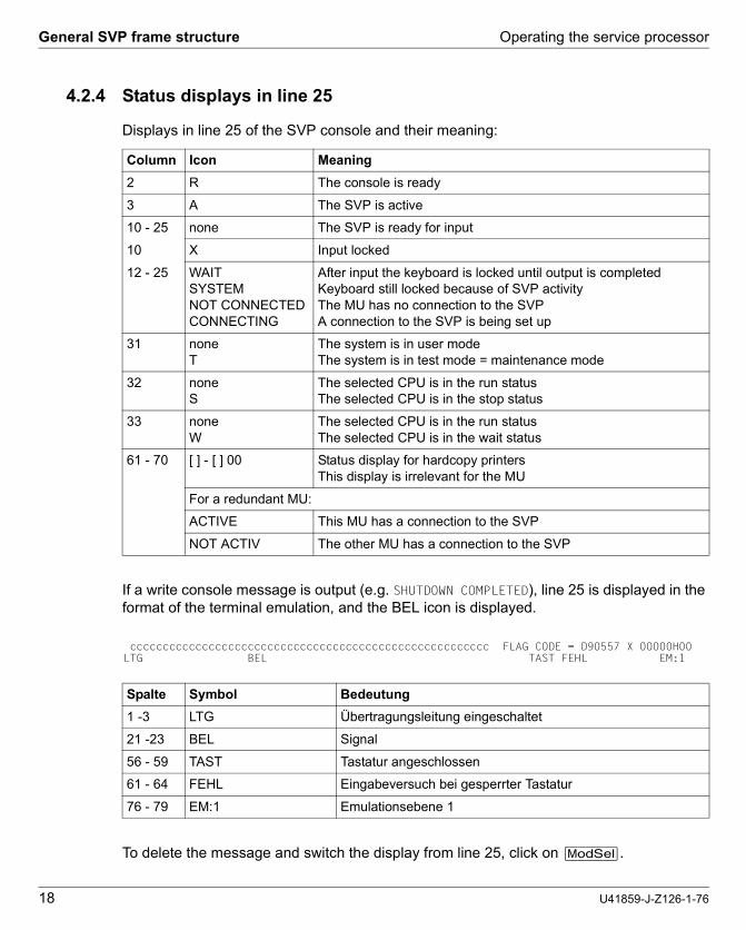
4.2.4 Status displays in line 25
Displays in line 25 of the SVP console and their meaning:
If a write console message is output (e.g. SHUTDOWN COMPLETED), line 25 is displayed in the format of the terminal emulation, and the BEL icon is displayed.
To delete the message and switch the display from line 25, click on [ModSel].
Column Icon Meaning
2 R The console is ready
3 A The SVP is active
10 - 25 none The SVP is ready for input
10 X Input locked
12 - 25 WAIT SYSTEM NOT CONNECTEDCONNECTING
After input the keyboard is locked until output is completedKeyboard still locked because of SVP activityThe MU has no connection to the SVPA connection to the SVP is being set up
31 none T
The system is in user modeThe system is in test mode = maintenance mode
32 none S
The selected CPU is in the run statusThe selected CPU is in the stop status
33 none W
The selected CPU is in the run statusThe selected CPU is in the wait status
61 - 70 [ ] - [ ] 00 Status display for hardcopy printers This display is irrelevant for the MU
For a redundant MU:
ACTIVE This MU has a connection to the SVP
NOT ACTIV The other MU has a connection to the SVP
Spalte Symbol Bedeutung
1 -3 LTG Übertragungsleitung eingeschaltet
21 -23 BEL Signal
56 - 59 TAST Tastatur angeschlossen
61 - 64 FEHL Eingabeversuch bei gesperrter Tastatur
76 - 79 EM:1 Emulationsebene 1
ccccccccccccccccccccccccccccccccccccccccccccccccccccccc FLAG CODE = D90557 X 00000H00LTG BEL TAST FEHL EM:1

Operating the service processor Using SVP frames
U41859-J-Z126-1-76 19
Dok
usch
abl
onen
19x
24 V
ers
ion
7.4
us fü
r F
ram
eM
aker
V7
.xvo
m 0
9.02
.201
0©
cog
nita
s G
mbH
200
1-2
010
Dok
usch
ablo
nen
19x2
4 V
ersi
on
7.4u
s fü
r F
ram
eM
aker
V7
.xvo
m 0
9.0
2.20
10©
cog
nita
s G
mb
H 2
001
-20
1026
. Ju
ne 2
015
Sta
nd
10:2
0.05
Pfa
d: P
:\FT
S-B
S\S
erve
r\S
E-S
erve
r\S
E-D
oku
\130
3907
_B
A_
SU
_39
0\p
rod_
e\ba
_su
390.
k05
4.3 Using SVP frames
You assign a job to the SVP by invoking the relevant frame, selecting the desired function, and specifying the required parameters. To select a function or specify a parameter, you must enter the alphanumeric characters shown in the frame in the input fields marked by an arrow (=>). After an entry, the cursor automatically switches to the next entry field. You can select entry fields manually with the tabulator key or arrow keys. Once you have entered all the functions and parameters assigned to a job, press the [ENTER] key. In some frames, SVP functions can also be initiated by actuating the corresponding function key (also known as pfkey).
Instead of selecting a function, you can also enter a command in the command input line in all frames (screen line 24) and assign a job to the SVP in this way. Frames can also be selected using the FRËFrame-ID, e.g. FR ML (to switch to the MODE SELECTION FRAME, in upper or lower case). A command entered in line 24 takes priority over a selected frame function.
4.3.1 SVP functions (function keys)
A virtual keyboard is available to you for making entires on the SVP console.
Ê Click the keyboard icon at the top right to open the virtual keyboard. Clicking the icon again closes the keyboard.
Function keys (pfkeys) [PF1] through [PF24] and [Clear] and [Cancel] are located in the upper part of the virtual keyboard. You can trigger the corresponding SVP functions by clicking with the mouse.

Using SVP frames Operating the service processor
20 U41859-J-Z126-1-76
Some function keys are labeled with the name of the function they are most frequently used for (e.g. [INDEX] instead of [PF2]).
Function key [PF20] (stop function) has no function in order to provide protection against it being pressed inadvertently and is therefore not offered on the virtual keyboard.
The table 1 on page 20 shows the function keys and their functions which are applicable for most frames. Any different function allocations of function keys are described in the frames concerned. As an alternative, SVP functions can be called and entries made in the frames using your keyboard.
i Some of the function keys listed here only have a function in CE mode (CE=Customer Engineer, maintenance mode) and are used solely by Customer Support personnel. Customer Support can enable and disable CE mode on the server using a sliding switch on the inside of the maintenance panel or on the MU using a CLI command.
PF.. Function key of the virtual keyboard
Alternative entry on the keyboard
Name Function
PF1 [PF1] [ESC] [F1] Help Help functions
PF2 [INDEX] [ESC] [F2] Index Only effective in CE mode:switches to the index frame.
PF3 [RETURN] [ESC] [F3] Return Switches to the preceding frame.
PF4 [PF4] [ESC] [F4] Frame-specific function is performed.
PF5 [PF5] [ESC] [F5] Frame-specific function is performed.
PF6 [Can/Erase] [ESC] [F6] Cancel/ Erase Input
Command or input data is deleted.
PF7 [Page up] [ESC] [F7] Page up The previous screen contents are displayed
PF8 [Page down] [ESC] [F8] Page down The next screen contents are displayed
PF9 [PF9] [ESC] [F9] Frame-specific function is performed.
PF10 [PF10] [ESC] [F10] Frame-specific function is performed.
PF11 [PF11] [ESC] [SHIFT] [F1] Frame-specific function is performed.
PF12 [PF12] [ESC] [SHIFT] [F2] Frame-specific function is performed.
PF13 [RECALL] [ESC] [SHIFT] [F3] Recall Previous SVP commands are displayed in the command line. They can then be executed again with changed operands
PF14 [PF14] [ESC] [SHIFT] [F4] Frame-specific function is performed.
PF15 [PF15] [ESC] [SHIFT] [F5] Frame-specific function is performed.
Table 1: Function keys for SVP functions (part 1 of 2)

Operating the service processor Using SVP frames
U41859-J-Z126-1-76 21
Dok
usch
abl
onen
19x
24 V
ers
ion
7.4
us fü
r F
ram
eM
aker
V7
.xvo
m 0
9.02
.201
0©
cog
nita
s G
mbH
200
1-2
010
Dok
usch
ablo
nen
19x2
4 V
ersi
on
7.4u
s fü
r F
ram
eM
aker
V7
.xvo
m 0
9.0
2.20
10©
cog
nita
s G
mb
H 2
001
-20
1026
. Ju
ne 2
015
Sta
nd
10:2
0.05
Pfa
d: P
:\FT
S-B
S\S
erve
r\S
E-S
erve
r\S
E-D
oku
\130
3907
_B
A_
SU
_39
0\p
rod_
e\ba
_su
390.
k05
PF16 [PF16] [ESC] [SHIFT] [F6] Change CPU Selects the CPU for which the subse-quent commands are to apply. This CPU is then connected logically with the SVP.
PF17 [PF17] [ESC] [SHIFT] [F7] not assigned
PF18 [Step] [ESC] [SHIFT] [F8] Step Executes the next command if the server is in Single Cycle Instruction Mode
PF19 [PF19] [ESC] [SHIFT] [F9] ARMSS management
Changes the user rights of an existing ARMSS connection
PF20 [ESC] [SHIFT] [F10] Stop Only effective in CE mode:Stops the selected CPU
PF21 [START] [SHIFT] [F5] Start Starts the selected CPU
PF22 [PF22] [SHIFT] [F6] not assigned
PF23 [ModSel] [SHIFT] [F7] Mode Select – Switches to the MODE SELECTION FRAME
– Erases WRITE-CONSOL message on the screen (e.g. SHUTDOWN COMPLETED)
– Erases BEL display in screen line 25
PF24 [ModChg] [F7] ModeChange Switches back and forth between FJ-PROGRAM FRAME and SVP FRAME (for Customer Support only if appropriate settings apply!)
[Cancel] [F5] Cancel/Reset Cancel input, release keyboard
[Clear] [F6] Refresh/Clear The last frame output is displayed again.All inputs of the current frame made to date are reset.
PF.. Function key of the virtual keyboard
Alternative entry on the keyboard
Name Function
Table 1: Function keys for SVP functions (part 2 of 2)

Using SVP frames Operating the service processor
22 U41859-J-Z126-1-76
4.3.2 Switching between SVP frames
A switch between the frames is only possible within a specified scheme or via an FR command. The possible switches between the frames are possible:
Figure 5: Switching between the frames
Explanation of the figure:
The frames are represented by this symbol:
Each frame has an ID consisting of two letters derived from the frame name. In the above example the MODE SELECTION FRAME is also shown with the ID ML.
Arrows and SVP functions show how and with which button you can switch to another frame.
ML MODE SELECTION FRAME
LD PROGRAM LOAD FRAME
ST STATUS DISPLAY FRAME
AD ALTER/DISPLAY FRAME
MA MANUAL OPERATION FRAME
ME MESSAGE FRAME
CH CH/SUBCH STATUS DISPLAY FRAME
1 REAL CLOCK
AU AUXILIARY FRAME: MENU
2 IORSF CONTROL
3 RELATED SCB’S
5 LOAD PRESET1 4 POWER STAND-BY/IMPL
MF MAINTENANCE SUPPORT FRAME
FR-Kommando [ModSel]
[RETURN]
PA PERFORMANCE ANALYSER
Frame-Kennung Frame-Name
MODE SELECTION FRAMEML

Operating the service processor Using SVP frames
U41859-J-Z126-1-76 23
Dok
usch
abl
onen
19x
24 V
ers
ion
7.4
us fü
r F
ram
eM
aker
V7
.xvo
m 0
9.02
.201
0©
cog
nita
s G
mbH
200
1-2
010
Dok
usch
ablo
nen
19x2
4 V
ersi
on
7.4u
s fü
r F
ram
eM
aker
V7
.xvo
m 0
9.0
2.20
10©
cog
nita
s G
mb
H 2
001
-20
1026
. Ju
ne 2
015
Sta
nd
10:2
0.05
Pfa
d: P
:\FT
S-B
S\S
erve
r\S
E-S
erve
r\S
E-D
oku
\130
3907
_B
A_
SU
_39
0\p
rod_
e\ba
_su
390.
k05
4.3.3 Options for switching between frames
The following table shows the options for switching to another frame in the SVP window.
Button Effect
[INDEX] Only in CE mode: by clicking on this button you switch from any frame directly to the index frame. The selection of the desired frame can then be made by entering the frame ID in the index frame.
[RETURN] This button switches back to the previous frame or to the higher-level frame.
[ModSel] This button switches switches from any frame to the MODE SELECTION FRAME.
Frame selection Enter a frame code in the MODE SELECTION FRAME (e.g. ST, AU, AU5)
Change to subframes
You can change to a subframe by selecting it from the main frame or from a subframe that has already been invoked. This can be done:– with SVP function calls (the buttons are shown in the corresponding frame or
subframe)– by selecting a function with or without entering a parameter.
FR command It is possible to switch to any frame with the FR command. The command is entered in the command line (screen line 24) of a frame. It has the following format:FR XX (XX is the code of the desired frame; see figure 5 on page 22)

SVP frames and subframes Operating the service processor
24 U41859-J-Z126-1-76
4.4 SVP frames and subframes
The frames are used by the operator for sending jobs to the SVP and for receiving replies from the SVP.
Some frames have up to seven subframes. The subframes contain other, more detailed functions and information which does not fit in the main frame.
Several frames display settings stored by the SVP. The current setting is indicated by an “>” arrow before the corresponding menu item. An example of this is provided in figure 6: STOP/START MODE applies only for the target CPU (selected CPU).
i This manual only describes the frames required by the operator.
4.4.1 (ML) MODE SELECTION FRAME
Figure 6: MODE SELECTION FRAME screen
By making entries in this frame and pressing the [ENTER] key, you can switch to other frames or execute various basic functions.
----- MODE SELECTION FRAME ----- E90L01G FUNCTION=>
- EXECUTION - - SELECTION - CPU SELECT=> - 0 1 2 3 4 - *1 CPU STOP *LD PROGRAM LOAD - - *ST STATUS DISPLAY *2 INTERRUPT *MA MANUAL OPERATION STOP/START MODE=> *AD ALTER/DISPLAY *3 TOD ENABLE *ME MESSAGE *1 ALL CPU *CH CH/SUBCH STATUS >2 TARGET CPU *4 SYSTEM RESET *AU AUXILIARY *MF MSF *5 SYSTEM RESET CLEAR *PA PERFORMANCE ANALYZER
*6 STORE STATUS
*7 RESTART
CL-0 CPU-0 CHP-0 RUN RA []-[]00

Operating the service processor SVP frames and subframes
U41859-J-Z126-1-76 25
Dok
usch
abl
onen
19x
24 V
ers
ion
7.4
us fü
r F
ram
eM
aker
V7
.xvo
m 0
9.02
.201
0©
cog
nita
s G
mbH
200
1-2
010
Dok
usch
ablo
nen
19x2
4 V
ersi
on
7.4u
s fü
r F
ram
eM
aker
V7
.xvo
m 0
9.0
2.20
10©
cog
nita
s G
mb
H 2
001
-20
1026
. Ju
ne 2
015
Sta
nd
10:2
0.05
Pfa
d: P
:\FT
S-B
S\S
erve
r\S
E-S
erve
r\S
E-D
oku
\130
3907
_B
A_
SU
_39
0\p
rod_
e\ba
_su
390.
k05
FUNCTION => The desired function can be selected by entry of a number listed in the EXECUTION column or a letter combination listed in the SELECTION column.
SELECTION=> After entering the appropriate letter combination you can switch to the following SVP FRAMEs:
EXECUTION The following function is executed after the corresponding number has been entered:
V CAUTION!The functions are executed according to the entries in the CPU SELECT and STOP/START MODE fields (see table on next page)!
LD PROGRAM LOAD Load BS2000 page 27
ST STATUS DISPLAY Display status page 34
MA MANUAL OPERATION Manual operations page 35
AD ALTER/DISPLAY Alter/display storage/register page 37
ME MESSAGE Display message page 41
CH CH/SUBCH STATUS Display status of channel/subchannel page 42
AU AUXILIARY Auxiliary controls page 44
MF MSF Display FLAG codes page 53
PA PERORMANCE ANALYZER Performance analysis page 54
1 CPU STOP stops either the CPU selected in the CPU SELECT and STOP/START MODE fields or all CPUs
2 INTERRUPT creates an external interrupt for the CPU selected in the fields CPU SELECT and STOP/START MODE
3 TOD ENABLE time entry is enabled
4 SYSTEM RESET all CPUs, channel processors, channels and controllers are reset
5 SYSTEM RESET CLEAR as 4; in addition, the working memory is erased
6 STORE STATUS selected CPU is stopped, the status is stored
7 RESTART starts the system again (this function is only possible if the operating system has a restart facility)

SVP frames and subframes Operating the service processor
26 U41859-J-Z126-1-76
CPU SELECT => A particular CPU can be selected here for the functions in the EXECUTION selection menu (see the previous page). The CPUs available are displayed in the two lines below this.
0 ... F Selection of a particular CPU
STOP/START MODE => This can be used to indicate whether the functions in the EXECUTION selection menu are to be carried out for all CPUs or only for the CPU in the CPU SELECT field.
The following table shows all the functions that can be meaningfully combined:
1 ALL CPU all CPUs are selected
2 TARGET CPU only the CPU selected in the CPU SELECT field is selected
Function CPU SELECT STOP/START MODE Effect on:
CPU STOP - 1 All CPU all CPUs
0 ... F 2 TARGET CPU selected CPU
INTERRUPTSTORE STATUSRESTART
0 ... F 2 TARGET CPU selected CPU
TOD ENABLE SYSTEM RESET SYSTEM RESET CLEAR
– – all CPUs
–: unusable

Operating the service processor SVP frames and subframes
U41859-J-Z126-1-76 27
Dok
usch
abl
onen
19x
24 V
ers
ion
7.4
us fü
r F
ram
eM
aker
V7
.xvo
m 0
9.02
.201
0©
cog
nita
s G
mbH
200
1-2
010
Dok
usch
ablo
nen
19x2
4 V
ersi
on
7.4u
s fü
r F
ram
eM
aker
V7
.xvo
m 0
9.0
2.20
10©
cog
nita
s G
mb
H 2
001
-20
1026
. Ju
ne 2
015
Sta
nd
10:2
0.05
Pfa
d: P
:\FT
S-B
S\S
erve
r\S
E-S
erve
r\S
E-D
oku
\130
3907
_B
A_
SU
_39
0\p
rod_
e\ba
_su
390.
k05
4.4.2 (LD) PROGRAM LOAD FRAME: BASIC
Figure 7: PROGRAM LOAD FRAME: BASIC screen
An IPL is executed by entering a load function and pressing the [ENTER] key. The predefined parameters in (AU5) AUXILIARY FRAME: LOAD PRESET are used.
LOAD FUNCTION ==> The following function is selected after the corresponding number has been entered:
1 START AUTO executes IPL: automatic startup
2 START FAST executes IPL: fast startup
3 START DIAL executes IPL: dialog startup
4 START not used
5 SYSTEM DUMP executes SLED
----- PROGRAM LOAD FRAME: BASIC ----- E90L01G -LOAD FUNCTION- ==> *1 START AUTO *2 START FAST *3 START DIAL *4 START *5 SYSTEM DUMP
*ENTER EXECUTE *PF7 GO TO DETAIL-1 *FR AU5 GO TO PRESET(AU5 FRAME)
CL-0 CPU-0 CHP-0 RUN RA []-[]00

SVP frames and subframes Operating the service processor
28 U41859-J-Z126-1-76
Frame-specific functions
[ENTER] Executes IPL / SYSTEM DUMP
After making your entries in the mask and pressing the [ENTER] key, the following prompt will appear:
V CAUTION!The IPL must not be executed during system operation! If this instruction is not heeded, BS2000 will be aborted!
Ê Press the [Y] and [ENTER] keys to execute the IPL, or [N] and [ENTER] to cancel the procedure.
[Page up] Swap to PROGRAM LOAD FRAME: DETAIL-1 (see below)
FR AU5 Enters the frame command in line 24: Swap to AUXILIARY FRAME: LOAD PRESET1 (see page 50)
4.4.2.1 (LD) PROGRAM LOAD FRAME: DETAIL-1
Figure 8: PROGRAM LOAD FRAME: DETAIL-1 screen
By making entries in this frame and pressing the [ENTER] key you can control the execution of an IPL.
************************************ ** ARE YOU SURE ? (ENTER Y OR N) N ** ************************************
----- PROGRAM LOAD FRAME: DETAIL-1 ----- E90L01G
-LOAD FUNCTION- -IPL DEVICE- ==> ==> 2 *1 START AUTO *1 PRESET GROUP ------------------+ *2 START FAST >*2 CURRENT GROUP --------+ | *3 START DIAL *3 UNIT ADDRESS -+ + + *4 START A108 A108 A108 *5 SYSTEM DUMP XXXX XXXX *6 LOAD CLEAR -----+ XXXX XXXX *7 LOAD NON CLEAR -+ XXXX XXXX | +MT CONTROL- --- DETAIL-2 STATUS --- PARMS=> 1 ==> 1 VM MODE : AVM/EX >*1 NL EXA MODE : ENABLE *2 SL IPL EXEC : ENABLE *3 NL-REWIND *4 SL-REWIND *ENTER EXECUTE *PF3 GO TO BASIC FRAME *PF9 GO TO DETAIL-2
CL-0 CPU-0 CHP-0 RUN RA []-[]00

Operating the service processor SVP frames and subframes
U41859-J-Z126-1-76 29
Dok
usch
abl
onen
19x
24 V
ers
ion
7.4
us fü
r F
ram
eM
aker
V7
.xvo
m 0
9.02
.201
0©
cog
nita
s G
mbH
200
1-2
010
Dok
usch
ablo
nen
19x2
4 V
ersi
on
7.4u
s fü
r F
ram
eM
aker
V7
.xvo
m 0
9.0
2.20
10©
cog
nita
s G
mb
H 2
001
-20
1026
. Ju
ne 2
015
Sta
nd
10:2
0.05
Pfa
d: P
:\FT
S-B
S\S
erve
r\S
E-S
erve
r\S
E-D
oku
\130
3907
_B
A_
SU
_39
0\p
rod_
e\ba
_su
390.
k05
Before completing this frame, check whether the correct firmware for operating Native BS2000 or VM2000 has been loaded by the SVP. Information on this is provided in the DETAIL-2 STATUS field.
DETAIL-2 STATUS In this position the current settings of the PROGRAM LOAD FRAME: DETAIL-2 are displayed.
If the setting is not correct, click on [PF9] to correct the entry in PROGRAM LOAD FRAME: DETAIL-2. After you have made the correction and clicked on [PF9], the setting is stored and you are returned to this frame (see page 32).
If the setting is correct, complete this frame and execute the IPL.
LOAD FUNCTION ==> The following function is selected after the corresponding number has been entered:
Functions 6 or 7 must be used for an IPL from a real or emulated tape device. In addition, function 3 must be selected at MT CONTROL (see page 31).
important display
VM MODE: Loaded firmware
NATIVE for BS2000 operation
AVM/EX for VM2000
1 START AUTO executes IPL: automatic startup
2 START FAST executes IPL: fast startup
3 START DIAL executes IPL: dialog startup
4 START not used
5 SYSTEM DUMP executes SLED
6 LOAD CLEAR clears main memory before IPL
7 LOAD NON CLEAR does not clear main memory before IPL

SVP frames and subframes Operating the service processor
30 U41859-J-Z126-1-76
IPL DEVICE ==> By entering the corresponding number in this field you can specify from which device group an IPL is to be executed.
PARMS => A maximum of 8 characters can be entered in this field. Their position and meaning are listed below:
1 PRESET GROUP The first device address in this column is the device from which an IPL is to be executed. The order and number were specified previously in (AU5) AUXILIARY FRAME: LOAD PRESET-1.If IPL is terminated normally, the device address list is transferred from the PRESET GROUP to the CURRENT GROUP.If the IPL is unsuccessful, the next device address from the PRESET GROUP is reloaded. If this loading is terminated normally, this device address heads the CURRENT GROUP.
2 CURRENT GROUP The first device address in this column is the device from which the last IPL was executed.If the loading from this device is unsuccessful, the IPL is repeated with the next device address. If it is terminated normally, this address then heads the CURRENT GROUP
3 UNIT ADDRESS A new device address from which the operating system is to be loaded can be entered here. If the IPL is terminated normally, this device address is put in the first position in the CURRENT GROUP. If the IPL is unsuccessful, the loading is not repeated.
Position 1 Ë1
loading BS2000 loading VM2000
Position 2 - 5
mn The mnemonic pair of an SKP console can be entered here if the standard consoles with the mnemonic pairs C2C3 and C4C5 are not available for the IPL.
Position 6 - 8
not used

Operating the service processor SVP frames and subframes
U41859-J-Z126-1-76 31
Dok
usch
abl
onen
19x
24 V
ers
ion
7.4
us fü
r F
ram
eM
aker
V7
.xvo
m 0
9.02
.201
0©
cog
nita
s G
mbH
200
1-2
010
Dok
usch
ablo
nen
19x2
4 V
ersi
on
7.4u
s fü
r F
ram
eM
aker
V7
.xvo
m 0
9.0
2.20
10©
cog
nita
s G
mb
H 2
001
-20
1026
. Ju
ne 2
015
Sta
nd
10:2
0.05
Pfa
d: P
:\FT
S-B
S\S
erve
r\S
E-S
erve
r\S
E-D
oku
\130
3907
_B
A_
SU
_39
0\p
rod_
e\ba
_su
390.
k05
MT CONTROL ==> IPL from tape:
Function 3 must be selected for an IPL of a real or emulated tape device.
Frame-specific functions
[ENTER] Executes IPL / SYSTEM DUMP
After making your entries in the mask and pressing the [ENTER] key, the following prompt will appear:
v CAUTION!The IPL must not be executed during system operation! If this instruction is not heeded, BS2000 will be aborted!
Ê Press the [Y] and [ENTER] keys to execute the IPL, or [N] and [ENTER] to cancel the procedure.
[RETURN] Swap to PROGRAM LOAD FRAME: BASIC (see page 27)
[PF9] Swap to PROGRAM LOAD FRAME: DETAIL-2 (see next page).
1 NL from current tape position
2 SL skip label then load
3 NL-REWIND rewind then load
4 SL-REWIND rewind, skip label then load
************************************ ** ARE YOU SURE ? (ENTER Y OR N) N ** ************************************

SVP frames and subframes Operating the service processor
32 U41859-J-Z126-1-76
4.4.2.2 (LD) PROGRAM LOAD FRAME: DETAIL-2
Figure 9: PROGRAM LOAD FRAME: DETAIL-2 screen
By making an entry in this frame and pressing the [ENTER] key, you set the operating mode.
VM MODE ==> Selection of the firmware to be loaded from SVP
IPL EXECUTION ==> IPL execution
If there are changes to the VM MODE and IPL EXECUTION => 2, only the other firmware is loaded and no IPL is executed.
1 NATIVE for BS2000 operation
2 AVM/EX for VM2000
1 ENABLE executes IPL
2 DISABLE does not execute IPL
----- PROGRAM LOAD FRAME: DETAIL-2 ----- E90L01G
-VM MODE- -IPL EXECUTION- ==> 2 ==> 1 *1 NATIVE >*1 ENABLE >*2 AVM/EX *2 DISABLE
*ENTER EXECUTE *PF3 GO TO BASIC FRAME *PF9 GO TO DETAIL-1
CL-0 CPU-0 CHP-0 RUN RA []-[]00

Operating the service processor SVP frames and subframes
U41859-J-Z126-1-76 33
Dok
usch
abl
onen
19x
24 V
ers
ion
7.4
us fü
r F
ram
eM
aker
V7
.xvo
m 0
9.02
.201
0©
cog
nita
s G
mbH
200
1-2
010
Dok
usch
ablo
nen
19x2
4 V
ersi
on
7.4u
s fü
r F
ram
eM
aker
V7
.xvo
m 0
9.0
2.20
10©
cog
nita
s G
mb
H 2
001
-20
1026
. Ju
ne 2
015
Sta
nd
10:2
0.05
Pfa
d: P
:\FT
S-B
S\S
erve
r\S
E-S
erve
r\S
E-D
oku
\130
3907
_B
A_
SU
_39
0\p
rod_
e\ba
_su
390.
k05
Frame-specific functions
[ENTER] Sets operating mode.
Ê After selecting the firmware to be loaded in the VM MODE ==> field and entering 2 in the IPL EXECUTION ==> field, press the [ENTER] key.
The following prompt appears on the screen:
v CAUTION!The operating mode must not be reset during system operation! If this instruction is not heeded, BS2000 will be aborted!
Ê Press the [Y] key to reload the firmware, or the [N] key to cancel the procedure. Confirm your entry with the [ENTER] key.
Ê After reloading the firmware, click on the [PF9] key to carry out IPL in PROGRAM LOAD FRAME: DETAIL-1.
[RETURN] Swap to PROGRAM LOAD FRAME: BASIC (see page 27)
[PF9] Swap to PROGRAM LOAD FRAME: DETAIL-1 (see page 28) without saving the changes you have made.
************************************ ** ARE YOU SURE ? (ENTER Y OR N) N ** ************************************

SVP frames and subframes Operating the service processor
34 U41859-J-Z126-1-76
4.4.3 (ST) STATUS DISPLAY FRAME
Figure 10: STATUS DISPLAY FRAME screen
This frame informs you about the current status of the server and its individual components (power on/off, online/offline, normal/maintenance state, etc.). Components which are not installed are not displayed. At most the following components are possible:– CPU: CPU-0 through CPU-F – I/O processor: IOP-0 through IOP-3 – Main Storage Unit: MSU-0 through MSU-3 – Channel box: CHEB-0 through CHEB-F
The important displays are the memory size, the addressing mode (MODE EXA or AVM/EX) and the availability of the SKP functionality (SVPM ENABLE display).

Operating the service processor SVP frames and subframes
U41859-J-Z126-1-76 35
Dok
usch
abl
onen
19x
24 V
ers
ion
7.4
us fü
r F
ram
eM
aker
V7
.xvo
m 0
9.02
.201
0©
cog
nita
s G
mbH
200
1-2
010
Dok
usch
ablo
nen
19x2
4 V
ersi
on
7.4u
s fü
r F
ram
eM
aker
V7
.xvo
m 0
9.0
2.20
10©
cog
nita
s G
mb
H 2
001
-20
1026
. Ju
ne 2
015
Sta
nd
10:2
0.05
Pfa
d: P
:\FT
S-B
S\S
erve
r\S
E-S
erve
r\S
E-D
oku
\130
3907
_B
A_
SU
_39
0\p
rod_
e\ba
_su
390.
k05
4.4.4 (MA) MANUAL OPERATION FRAME
Figure 11: MANUAL OPERATION FRAME screen
By making an entry in this frame and pressing the [ENTER] key, you can perform various manual operations.
Instructions on this frame are only executed when the CPU has been stopped (see message in frame line 23). The CPU status is displayed in line 22.
Ê Selection of a CPU by clicking on [PF16]
Ê Stopping of the selected CPU (see (ML) MODE SELECTION FRAME page 24)
FUNCTION => The following function is executed after the corresponding character has been entered and the [ENTER] key has been pressed:
1 RATE CONTROL defines program operation
2 ADRS COMPARE STOP sets mode for compare address stop
3 3 FIRM DUMP outputs a firmware dump to tape, MTC or an emulated tape device (for Customer Support only)
4 HSA DUMP executes HSA dump (for Customer Support only) (HSA Hardware/Software Area)
X EXECUTE executes functions 1 - 4

SVP frames and subframes Operating the service processor
36 U41859-J-Z126-1-76
The following table shows the additional entries required for each of the three main functions in other input fields:
RATE CONTROL => defines program operation
ADRS TYPE => Entries for address compare stop:
ADRS COMP SELECT => Address compare stop if compare stop address is same as
UNIT ADRS => Device address for output of a firmware dump
Input field
Function RATECONTROL
UNITADRS
ADRSTYPE
ADRSCOMP
SELECT
ADRSSET
ADRSCOMPMODE
1 RATE CONTROL o x x x x x
2 ADRS COMP STOP x x o o o o
3 FIRM DUMP x o x x x x
4 HSA DUMP x x x x x x
o: entry required x: entry not possible
1 PROCESS continual program operation
2 I-STEP step-by-step command execution
entry under ADRS SET is
1 ABSOLUTE absolute address
2 LOGICAL a logical address
1 ANY any address
2 OPERAND FETCH (OFETCH) operand read address
3 OPERAND STORE (OSTORE) operands write address
4 INSTRUCTION ADRS(IA) instruction address
5 IA & OFETCH instruction and operand read address
6 OFETCH & OSTORE operand read and write address
Operating the service processor SVP frames and subframes
U41859-J-Z126-1-76 37
Dok
usch
abl
onen
19x
24 V
ers
ion
7.4
us fü
r F
ram
eM
aker
V7
.xvo
m 0
9.02
.201
0©
cog
nita
s G
mbH
200
1-2
010
Dok
usch
ablo
nen
19x2
4 V
ersi
on
7.4u
s fü
r F
ram
eM
aker
V7
.xvo
m 0
9.0
2.20
10©
cog
nita
s G
mb
H 2
001
-20
1026
. Ju
ne 2
015
Sta
nd
10:2
0.05
Pfa
d: P
:\FT
S-B
S\S
erve
r\S
E-S
erve
r\S
E-D
oku
\130
3907
_B
A_
SU
_39
0\p
rod_
e\ba
_su
390.
k05
ADRS SET => Compare stop address
ADRS COMP MODE => Address compare stop mode
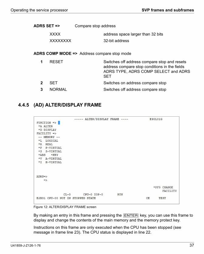
4.4.5 (AD) ALTER/DISPLAY FRAME
Figure 12: ALTER/DISPLAY FRAME screen
By making an entry in this frame and pressing the [ENTER] key, you can use this frame to display and change the contents of the main memory and the memory protect key.
Instructions on this frame are only executed when the CPU has been stopped (see message in frame line 23). The CPU status is displayed in line 22.
XXXX address space larger than 32 bits
XXXXXXXX 32-bit address
1 RESET Switches off address compare stop and resets address compare stop conditions in the fields ADRS TYPE, ADRS COMP SELECT and ADRS SET
2 SET Switches on address compare stop
3 NORMAL Switches off address compare stop

SVP frames and subframes Operating the service processor
38 U41859-J-Z126-1-76
Ê Selection of a CPU by clicking on [PF16]
Ê Stopping of the selected CPU (see (ML) MODE SELECTION FRAME page 24)
FUNCTION => The following function is selected after the corresponding letter has been entered:
FACILITY => Possible displays of memory areas with various addresses:
ADRS => Memory address
A ALTER change and modify memory contents
D DISPLAY display memory contents
L LOGICAL logical storage address
R REAL real storage address
P P-VIRTUAL primary virtual storage address
S S-VIRTUAL secondary virtual storage address
ABS absolute address
KEY memory protect key
V A-VIRTUAL address space virtual address
I H-VIRTUAL basic address space virtual address
XXXX address space larger than 32 bits
XXXXXXXX 32-bit address

Operating the service processor SVP frames and subframes
U41859-J-Z126-1-76 39
Dok
usch
abl
onen
19x
24 V
ers
ion
7.4
us fü
r F
ram
eM
aker
V7
.xvo
m 0
9.02
.201
0©
cog
nita
s G
mbH
200
1-2
010
Dok
usch
ablo
nen
19x2
4 V
ersi
on
7.4u
s fü
r F
ram
eM
aker
V7
.xvo
m 0
9.0
2.20
10©
cog
nita
s G
mb
H 2
001
-20
1026
. Ju
ne 2
015
Sta
nd
10:2
0.05
Pfa
d: P
:\FT
S-B
S\S
erve
r\S
E-S
erve
r\S
E-D
oku
\130
3907
_B
A_
SU
_39
0\p
rod_
e\ba
_su
390.
k05
Frame-specific functions
[PF9] When you click on this button, the following subframe is displayed:
Figure 13: ALTER/DISPLAY FRAME screen
By making the appropriate entries and pressing the [ENTER] key, you can use this frame to change and display the contents of important CPU registers.
Instructions on this frame are only executed when the CPU has been stopped (see message in frame line 23). The CPU status is displayed in line 22.
Ê Selection of a CPU by clicking on [PF16]
Ê Stopping of the selected CPU (see (ML) MODE SELECTION FRAME page 24)
FUNCTION => The following function is selected after the corresponding letter has been entered:
A ALTER change and modify register contents
D DISPLAY display register contents

SVP frames and subframes Operating the service processor
40 U41859-J-Z126-1-76
FACILITY => Possible displays of registers:
ADRS => no input required
Frame-specific functions
[PF9] returns to the frame for memory display
GR General register
PSW Program status word
CR Control register
FCR Feature control register
FPR Floating-point register
PRX Prefix register
AR Access register
HR Hyper register
ECR Extended control register
AMR Address modulation register
XCR Extended control register
EX EPRX Extended prefix register
Additional display, if IEEE Arithmetic Operation Mechanism is activated:
FPC Floating point control register
Operating the service processor SVP frames and subframes
U41859-J-Z126-1-76 41
Dok
usch
abl
onen
19x
24 V
ers
ion
7.4
us fü
r F
ram
eM
aker
V7
.xvo
m 0
9.02
.201
0©
cog
nita
s G
mbH
200
1-2
010
Dok
usch
ablo
nen
19x2
4 V
ersi
on
7.4u
s fü
r F
ram
eM
aker
V7
.xvo
m 0
9.0
2.20
10©
cog
nita
s G
mb
H 2
001
-20
1026
. Ju
ne 2
015
Sta
nd
10:2
0.05
Pfa
d: P
:\FT
S-B
S\S
erve
r\S
E-S
erve
r\S
E-D
oku
\130
3907
_B
A_
SU
_39
0\p
rod_
e\ba
_su
390.
k05
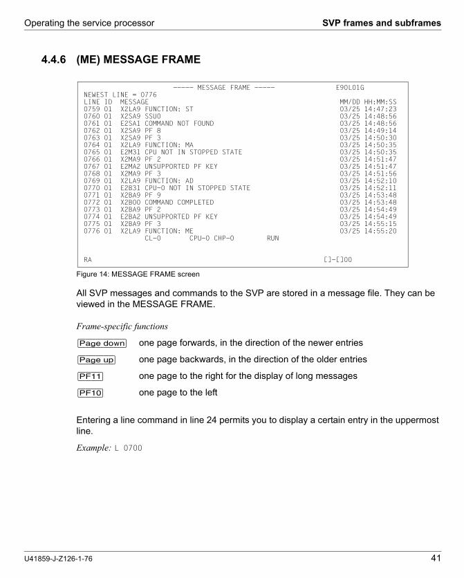
4.4.6 (ME) MESSAGE FRAME
Figure 14: MESSAGE FRAME screen
All SVP messages and commands to the SVP are stored in a message file. They can be viewed in the MESSAGE FRAME.
Frame-specific functions
[Page down] one page forwards, in the direction of the newer entries
[Page up] one page backwards, in the direction of the older entries
[PF11] one page to the right for the display of long messages
[PF10] one page to the left
Entering a line command in line 24 permits you to display a certain entry in the uppermost line.
Example: L 0700
----- MESSAGE FRAME ----- E90L01G NEWEST LINE = 0776 LINE ID MESSAGE MM/DD HH:MM:SS 0759 01 X2LA9 FUNCTION: ST 03/25 14:47:23 0760 01 X2SA9 SSU0 03/25 14:48:56 0761 01 E2SA1 COMMAND NOT FOUND 03/25 14:48:56 0762 01 X2SA9 PF 8 03/25 14:49:14 0763 01 X2SA9 PF 3 03/25 14:50:30 0764 01 X2LA9 FUNCTION: MA 03/25 14:50:35 0765 01 E2M31 CPU NOT IN STOPPED STATE 03/25 14:50:35 0766 01 X2MA9 PF 2 03/25 14:51:47 0767 01 E2MA2 UNSUPPORTED PF KEY 03/25 14:51:47 0768 01 X2MA9 PF 3 03/25 14:51:56 0769 01 X2LA9 FUNCTION: AD 03/25 14:52:10 0770 01 E2B31 CPU-0 NOT IN STOPPED STATE 03/25 14:52:11 0771 01 X2BA9 PF 9 03/25 14:53:48 0772 01 X2B00 COMMAND COMPLETED 03/25 14:53:48 0773 01 X2BA9 PF 2 03/25 14:54:49 0774 01 E2BA2 UNSUPPORTED PF KEY 03/25 14:54:49 0775 01 X2BA9 PF 3 03/25 14:55:15 0776 01 X2LA9 FUNCTION: ME 03/25 14:55:20 CL-0 CPU-0 CHP-0 RUN RA []-[]00

SVP frames and subframes Operating the service processor
42 U41859-J-Z126-1-76
4.4.7 (CH) CH/SUBCH STATUS DISPLAY FRAME: CHANNEL
Figure 15: CH/SUBCH STATUS DISPLAY FRAME: CHANNEL screen
By making entries in the input fields and pressing the [ENTER] key, you display the status of the I/O system. Further subframes are supplied in conjunction with FUNCTION 2 to 5.
FUNCTION => The following information is displayed on the screen after the corre-sponding number has been entered:
1 CH STATUS channel status (additional input in CHP NO field)
2 SUBCH STATUS subchannel status (additional input in the fields CHPID and LINKADR)
3 LINK STATUS LINK status of a type-S channel (type-S channel not supported on SU /390)
4 FC PORT STATUS Port status of a type-FC channel(additional input in PCHAD field)
5 ONA PORT STATUS Port status of an ONA channel (Optical Network Adapter, not supported by BS2000)

Operating the service processor SVP frames and subframes
U41859-J-Z126-1-76 43
Dok
usch
abl
onen
19x
24 V
ers
ion
7.4
us fü
r F
ram
eM
aker
V7
.xvo
m 0
9.02
.201
0©
cog
nita
s G
mbH
200
1-2
010
Dok
usch
ablo
nen
19x2
4 V
ersi
on
7.4u
s fü
r F
ram
eM
aker
V7
.xvo
m 0
9.0
2.20
10©
cog
nita
s G
mb
H 2
001
-20
1026
. Ju
ne 2
015
Sta
nd
10:2
0.05
Pfa
d: P
:\FT
S-B
S\S
erve
r\S
E-S
erve
r\S
E-D
oku
\130
3907
_B
A_
SU
_39
0\p
rod_
e\ba
_su
390.
k05
IOP NO => channel processor 0 ... 7
CHPID => channel path number 000 ... 0FF
LCHADR => logical channel address no input required
LINKADR => link address for type-S channel (not supported on SU /390)
LCUADR => logical control unit address no input required
PCHAD => physical channel address 000 ... 0FF
Frame-specific functions
[PF10] Display of channels with lower addresses.
[PF11] Display of channels with higher addresses.

SVP frames and subframes Operating the service processor
44 U41859-J-Z126-1-76
4.4.8 (AU) AUXILIARY FRAME: MENU
Figure 16: AUXILIARY FRAME: MENU screen
You can move to other frames by making entries in this menu frame and pressing the [ENTER] key.
SELECTION => The following subframes are displayed on the screen by entering the appropriate number:
1 REAL CLOCK displaying/setting SVP clock page 45
2 IORSF CONTROL displaying/editing IORSF page 46
3 RELATED SCB memory size for related SCBs page 48
4 POWER STAND-BY/IMPL executing POWER STAND-BY or IMPL page 49
5 LOAD PRESET presetting LOAD FRAME page 50

Operating the service processor SVP frames and subframes
U41859-J-Z126-1-76 45
Dok
usch
abl
onen
19x
24 V
ers
ion
7.4
us fü
r F
ram
eM
aker
V7
.xvo
m 0
9.02
.201
0©
cog
nita
s G
mbH
200
1-2
010
Dok
usch
ablo
nen
19x2
4 V
ersi
on
7.4u
s fü
r F
ram
eM
aker
V7
.xvo
m 0
9.0
2.20
10©
cog
nita
s G
mb
H 2
001
-20
1026
. Ju
ne 2
015
Sta
nd
10:2
0.05
Pfa
d: P
:\FT
S-B
S\S
erve
r\S
E-S
erve
r\S
E-D
oku
\130
3907
_B
A_
SU
_39
0\p
rod_
e\ba
_su
390.
k05
4.4.8.1 (AU1) AUXILIARY FRAME: REAL CLOCK
Figure 17: AUXILIARY FRAME: REAL CLOCK screen
When the screen is invoked, the current date and time of the SVP are displayed. Corrections can be entered in the line below. These corrections take effect when you click on [PF12].
i The SVP clock is synchronized by the MU (message in line 23: SET TIME COMMAND COMPLETED). The MU time is taken over by the SVP here.
Consequently an incorrect time specification in the MU must be corrected in the SVP. The administrator can set the local time in the MU in the SE Manager using the System time tab in the menu Hardware → Server (SE<model>) → <mu-name> (MU) → Management (see the "Operation and Administration" manual [7]).
Frame-specific functions
[Can/Erase] Delete input
[PF12] Corrections are carried out by the SVP
----- AUXILIARY FRAME: REAL CLOCK ----- E90L01G-03C+030
YYYY MM DD HH MM SS 2015.01.25 15:26:47 _
*PF6 CANCEL *PF12 TIMER SET
CL-0 CPU-0 CHP-0 RUN RA []-[]00
SVP frames and subframes Operating the service processor
46 U41859-J-Z126-1-76
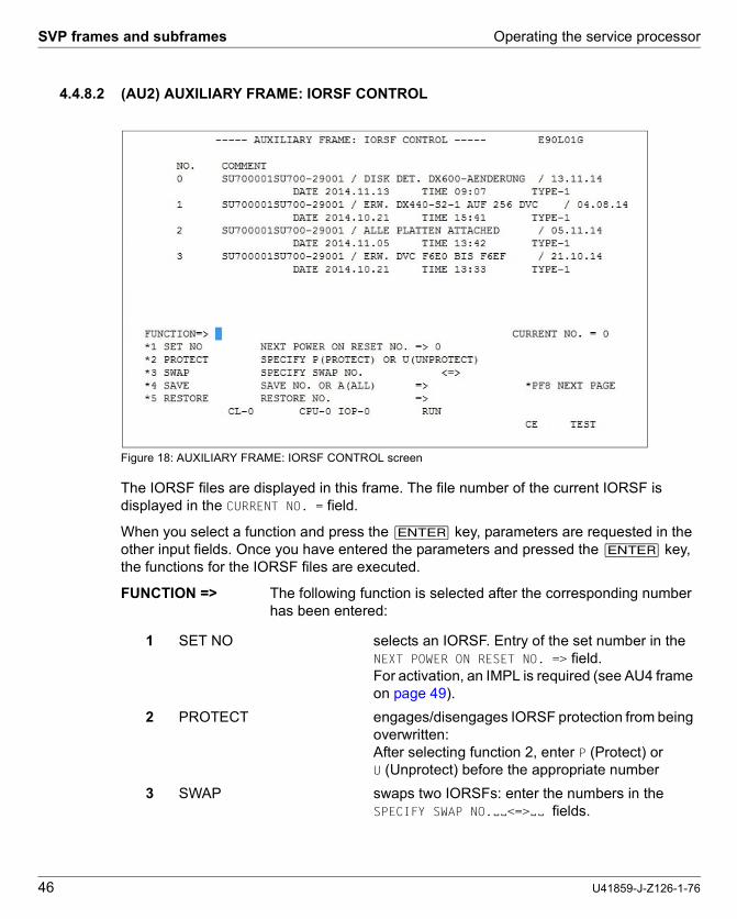
4.4.8.2 (AU2) AUXILIARY FRAME: IORSF CONTROL
Figure 18: AUXILIARY FRAME: IORSF CONTROL screen
The IORSF files are displayed in this frame. The file number of the current IORSF is displayed in the CURRENT NO. = field.
When you select a function and press the [ENTER] key, parameters are requested in the other input fields. Once you have entered the parameters and pressed the [ENTER] key, the functions for the IORSF files are executed.
FUNCTION => The following function is selected after the corresponding number has been entered:
1 SET NO selects an IORSF. Entry of the set number in the NEXT POWER ON RESET NO. => field. For activation, an IMPL is required (see AU4 frame on page 49).
2 PROTECT engages/disengages IORSF protection from being overwritten:After selecting function 2, enter P (Protect) or U (Unprotect) before the appropriate number
3 SWAP swaps two IORSFs: enter the numbers in the SPECIFY SWAP NO.ËË<=>ËË fields.

Operating the service processor SVP frames and subframes
U41859-J-Z126-1-76 47
Dok
usch
abl
onen
19x
24 V
ers
ion
7.4
us fü
r F
ram
eM
aker
V7
.xvo
m 0
9.02
.201
0©
cog
nita
s G
mbH
200
1-2
010
Dok
usch
ablo
nen
19x2
4 V
ersi
on
7.4u
s fü
r F
ram
eM
aker
V7
.xvo
m 0
9.0
2.20
10©
cog
nita
s G
mb
H 2
001
-20
1026
. Ju
ne 2
015
Sta
nd
10:2
0.05
Pfa
d: P
:\FT
S-B
S\S
erve
r\S
E-S
erve
r\S
E-D
oku
\130
3907
_B
A_
SU
_39
0\p
rod_
e\ba
_su
390.
k05
NEXT POWER ON RESET NO. => Enter the number of the IORSF file which is to be activated after the next IMPL. You can only make an entry if you select function 1 beforehand.
SPECIFY SWAP NO.ËË<=>ËË Enter the numbers of two IORSF files which are to be swapped. You can only make entries if you select function 3 beforehand.
SAVE NO. OR A(ALL) ==> Ë Specify the number of the IORSF file which is to be saved. Specifying "A" saves all IORSF files. You can only make entries if you select function 4 beforehand.
RESTORE NO. ==> Ë Specify the number of the IORSF file which is to be restored. You can only make entries if you select function 5 beforehand.
Frame-specific functions
[Page down] Sets 4 to 7 are displayed
[Page up] Sets 0 to 3 are displayed
[PF8] The next page is displayed.
4 SAVE saves one or all IORSFs: enter the number or the value A (All) in the field SAVE NO. OR A(ALL) ==> Ë
5 RESTORE restores an IORSF: enter the numbers in the field RESTORE NO. ==> Ë
SVP frames and subframes Operating the service processor
48 U41859-J-Z126-1-76
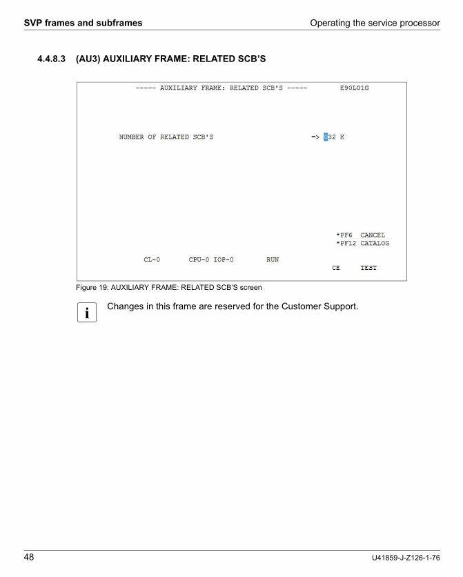
4.4.8.3 (AU3) AUXILIARY FRAME: RELATED SCB’S
Figure 19: AUXILIARY FRAME: RELATED SCB’S screen
i Changes in this frame are reserved for the Customer Support.

Operating the service processor SVP frames and subframes
U41859-J-Z126-1-76 49
Dok
usch
abl
onen
19x
24 V
ers
ion
7.4
us fü
r F
ram
eM
aker
V7
.xvo
m 0
9.02
.201
0©
cog
nita
s G
mbH
200
1-2
010
Dok
usch
ablo
nen
19x2
4 V
ersi
on
7.4u
s fü
r F
ram
eM
aker
V7
.xvo
m 0
9.0
2.20
10©
cog
nita
s G
mb
H 2
001
-20
1026
. Ju
ne 2
015
Sta
nd
10:2
0.05
Pfa
d: P
:\FT
S-B
S\S
erve
r\S
E-S
erve
r\S
E-D
oku
\130
3907
_B
A_
SU
_39
0\p
rod_
e\ba
_su
390.
k05
4.4.8.4 (AU4) AUXILIARY FRAME: POWER STAND-BY/IMPL
Figure 20: AUXILIARY FRAME: POWER STAND-BY/IMPL screen
By making an entry in this frame and pressing the [ENTER] key, you can switch the server off or re-initialize it.
FUNCTION => The following function is selected after the corresponding number has been entered:
After you have selected a function and pressed the [ENTER] key, the following prompt will appear:
v CAUTION!POWER STAND-BY or IMPL may not be executed during system operation! If this instruction is not heeded, BS2000 will be aborted!
Ê Press the [Y] and [ENTER] keys to switch off the system or to execute an IMPL, or the [N] and [ENTER] keys to cancel the procedure.
1 POWER STAND-BY switches the Server Unit off; order: first devices connected to the PCI (Power Control Interface), then the servers (for further information on this see "Switching the SE700 / SE500 on and off" in the Basic Operating Manual [1])
2 IMPL executes IMPL
----- AUXILIARY FRAME: POWER STAND-BY/IMPL ----- E90L01G
FUNCTION=>
*1 POWER STAND-BY
*2 IMPL
CL-0 CPU-0 CHP-0 RUN RA []-[]00
************************************ ** ARE YOU SURE ? (ENTER Y OR N) N ** ************************************

SVP frames and subframes Operating the service processor
50 U41859-J-Z126-1-76
4.4.8.5 (AU5) AUXILIARY FRAME: LOAD PRESET1
Figure 21: AUXILIARY FRAME: LOAD PRESET1 screen
You can predefine the execution of an IPL by making an entry in this frame and clicking on [PF12].
START MODE ==> Predefine the loading mode by entering the appropriate number and comment for the BS2000 loading mode:
IPL DEVICE Entries in this field specify from which device an IPL should be executed.
1 START AUTO for automatic startup
2 START FAST for fast startup
3 START DIAL for dialog startup
4 START not used
1 PRESET GROUP Up to four unit addresses can be entered in the input field for PRESET GROUP. The operating system is loaded from the first device (IPL). In the case of an error, the IPL is executed by the next device listed.
----- AUXILIARY FRAME: LOAD PRESET1 ----- E90L01G
-START MODE- -IPL DEVICE- ==> 1 >1 START AUTO 1 PRESET GROUP -----------------+ *2 START FAST 2 CURRENT GROUP --------+ | *3 START DIAL 3 UNIT ADDRESS -+ + + *4 START A108 A108 A108 XXXX XXXX XXXX XXXX XXXX XXXX
-POWER ON IPL- ==> 2 *1 ENABLE >2 DISABLE-INITIAL FRAME- ==> 2 *1 LOAD FRAME(BASIC) *PF12 CATALOG >2 LOAD FRAME(DETAIL) *PF9 GO TO LOAD PRESET-2
CL-0 CPU-0 CHP-0 RUN RA []-[]00

Operating the service processor SVP frames and subframes
U41859-J-Z126-1-76 51
Dok
usch
abl
onen
19x
24 V
ers
ion
7.4
us fü
r F
ram
eM
aker
V7
.xvo
m 0
9.02
.201
0©
cog
nita
s G
mbH
200
1-2
010
Dok
usch
ablo
nen
19x2
4 V
ersi
on
7.4u
s fü
r F
ram
eM
aker
V7
.xvo
m 0
9.0
2.20
10©
cog
nita
s G
mb
H 2
001
-20
1026
. Ju
ne 2
015
Sta
nd
10:2
0.05
Pfa
d: P
:\FT
S-B
S\S
erve
r\S
E-S
erve
r\S
E-D
oku
\130
3907
_B
A_
SU
_39
0\p
rod_
e\ba
_su
390.
k05
POWER ON IPL ==> Here you determine the behavior of the SVP after switching on.
INITIAL FRAME ==> Here you can set the display form of the PROGRAM LOAD FRAME.
1 ENABLE automatically executes IPL after IMPL
2 DISABLE does not execute IPL, i.e. IPL must be triggered manually using PROGRAM LOAD FRAME: BASIC or PROGRAM LOAD FRAME: DETAIL-1
1 LOAD FRAME (BASIC) PROGRAM LOAD FRAME: BASIC (see page 27)
2 LOAD FRAME (DETAIL) PROGRAM LOAD FRAME: DETAIL-1 (see page 28)

SVP frames and subframes Operating the service processor
52 U41859-J-Z126-1-76
Frame-specific functions
[PF12] Storing settings
[PF9] switches to the LOAD PRESET2 screen
Figure 22: AUXILIARY FRAME: LOAD PRESET2 screen
You can set the operation mode by making an entry in this frame and clicking on [PF12].
VM MODE ==> Selection of the firmware to be loaded from SVP
START IPL NO ==> Selection of the IPL Start Mode number
Frame-specific functions
[PF12] Storing settings
[PF9] switches to the LOAD PRESET1 screen
1 NATIVE for BS2000 operation
2 AVM/EX for VM2000
1 FIX(1) Start Mode number 1 (automatic start)
2 CURRENT not used on the Server Unit
----- AUXILIARY FRAME: LOAD PRESET2 ----- E90L01G
-VM MODE- ==> 2 *1 NATIVE >2 AVM/EX
-START IPL NO- ==> 1 >1 FIX(1) *2 CURRENT
*PF12 CATALOG *PF9 GO TO LOAD PRESET-1
CL-0 CPU-0 CHP-0 RUN 0 RA []-[]00

Operating the service processor SVP frames and subframes
U41859-J-Z126-1-76 53
Dok
usch
abl
onen
19x
24 V
ers
ion
7.4
us fü
r F
ram
eM
aker
V7
.xvo
m 0
9.02
.201
0©
cog
nita
s G
mbH
200
1-2
010
Dok
usch
ablo
nen
19x2
4 V
ersi
on
7.4u
s fü
r F
ram
eM
aker
V7
.xvo
m 0
9.0
2.20
10©
cog
nita
s G
mb
H 2
001
-20
1026
. Ju
ne 2
015
Sta
nd
10:2
0.05
Pfa
d: P
:\FT
S-B
S\S
erve
r\S
E-S
erve
r\S
E-D
oku
\130
3907
_B
A_
SU
_39
0\p
rod_
e\ba
_su
390.
k05
4.4.9 (MF) MSF FRAME
Figure 23: MSF FRAME: FLAG CODE LOG DISPLAY screen
The SVP logs all FLAG codes. The FLAG codes are displayed when this frame is invoked. As from a certain priority, the FLAG codes are displayed in frame line 24.
Frame-specific functions
[PF1] help function
[Page up] one page backwards, in the direction of the newer entries
[Page down] one page forwards, in the direction of the older entries
i This frame is intended for use by Customer Support. You only reach FLAG CODE LOG DISPLAY via a subframe (call FR MF with Function -> L1) and then <L1>.
----- MSF FRAME: FLAG CODE LOG DISPLAY ----- E90L01G
INITIALIZED 2010.03.11 15:43:23 LAST SEQ 0538 NODE:SELF 1/14 SEQ UNIT FLAG CODE DATE TIME CT KIND LINK INFORMATION *0538 ICC A9 7M12 3C 006D2H00 03.16 16:50:42 ATTN HC27 SP4 AW 026D 0C 006D0H00 *0537 ICC A9 7M12 3C 00692H00 03.16 16:50:34 ATTN HC26 SP3 AW 0269 0C 00690H00 *0536 ICC A9 7M12 3C 002D2H00 03.16 16:50:28 ATTN HC25 SP2 AW 022D 0C 002D0H00 *0535 ICC A9 7MC4 3C 00642H00 03.16 16:50:18 ATTN HC24 SP1 AW XX64 0C 00640H00 *0534 ICC A9 7MC1 3C 00642H00 03.16 16:50:12 ATTN HC23 AW XX64 0C 00640H00 *0533 ICC A9 7M12 3C 00292H00 03.16 16:42:39 ATTN HC22 AW 0229 0C 00290H00 *0532 ICC A9 7M12 3C 006D2H00 03.16 16:42:33 ATTN HC21 AW 026D 0C 006D0H00 PF1:HELP PF7:PREV PAGE PF8:NEXT PAGE CL-0 CPU-0 CHP-0 RUN FLAG CODE = A97M123C 006D2H00 RA []-[]00

SVP frames and subframes Operating the service processor
54 U41859-J-Z126-1-76
4.4.10 (PA) PERFORMANCE ANALYZER FRAME
Figure 24: PERFORMANCE ANALYZER FRAME screen
i The PA frame is not intended for use.
---- PERFORMANCE ANALYZER FRAME ---- E90L01G
FUNCTION => STATUS DISABLE / STOP 1 ENABLE & ITEM SELECT LOGGING STOP 2 DISABLE 3 START & DISPLAY ------- CH BUSY LEVEL -------- 4 START & CH BUSY 0 < GREEN < 30 (%) 5 STOP 31 < WHITE < 100 (%) 6 LOGGING START 7 LOGGING STOP ------- INTERVAL TIME -------- 8 CPU LOG DISPLAY SAMPLING ==> 2 SEC. 9 CH LOG DISPLAY LOGGING ==> 1 MIN.
CL-0 CPU-0 CHP-0 RUN RA []-[]00

Operating the service processor Examples of SVP operation
U41859-J-Z126-1-76 55
Dok
usch
abl
onen
19x
24 V
ers
ion
7.4
us fü
r F
ram
eM
aker
V7
.xvo
m 0
9.02
.201
0©
cog
nita
s G
mbH
200
1-2
010
Dok
usch
ablo
nen
19x2
4 V
ersi
on
7.4u
s fü
r F
ram
eM
aker
V7
.xvo
m 0
9.0
2.20
10©
cog
nita
s G
mb
H 2
001
-20
1026
. Ju
ne 2
015
Sta
nd
10:2
0.05
Pfa
d: P
:\FT
S-B
S\S
erve
r\S
E-S
erve
r\S
E-D
oku
\130
3907
_B
A_
SU
_39
0\p
rod_
e\ba
_su
390.
k05
4.5 Examples of SVP operation
4.5.1 Selecting IORSF
The steps described below are required to load a specific IORSF the next time IMPL takes place or the next time the system is switched on.
IORSF with Level 2 is selected in the example below.
Requirement
You are logged in to the SE Manager and have opened the SVP console.
i An operator account has access to the SVP console when the individual right permits SVP access.
The MODE SELECTION FRAME is displayed on the screen:
Figure 25: MODE SELECTION FRAME screen
----- MODE SELECTION FRAME ----- E90L01G FUNCTION=>
- EXECUTION - - SELECTION - CPU SELECT=> - 0 1 2 3 4 - *1 CPU STOP *LD PROGRAM LOAD - - *ST STATUS DISPLAY *2 INTERRUPT *MA MANUAL OPERATION STOP/START MODE=> *AD ALTER/DISPLAY *3 TOD ENABLE *ME MESSAGE *1 ALL CPU *CH CH/SUBCH STATUS >2 TARGET CPU *4 SYSTEM RESET *AU AUXILIARY *MF MSF *5 SYSTEM RESET CLEAR *PA PERFORMANCE ANALYZER
*6 STORE STATUS
*7 RESTART
CL-0 CPU-0 CHP-0 RUN RA []-[]00

Examples of SVP operation Operating the service processor
56 U41859-J-Z126-1-76
Invoke the AUXILIARY FRAME: MENU screen
Ê Enter AU in the FUNCTION=> field and then press the [ENTER] key,
or
Ê enter the FR AU command in line 24 and press the [ENTER] key.
The AUXILIARY FRAME: MENU screen is displayed:
Figure 26: AUXILIARY FRAME: MENU screen
Frame-Kennung Frame-Name
MODE SELECTION FRAMEML

Operating the service processor Examples of SVP operation
U41859-J-Z126-1-76 57
Dok
usch
abl
onen
19x
24 V
ers
ion
7.4
us fü
r F
ram
eM
aker
V7
.xvo
m 0
9.02
.201
0©
cog
nita
s G
mbH
200
1-2
010
Dok
usch
ablo
nen
19x2
4 V
ersi
on
7.4u
s fü
r F
ram
eM
aker
V7
.xvo
m 0
9.0
2.20
10©
cog
nita
s G
mb
H 2
001
-20
1026
. Ju
ne 2
015
Sta
nd
10:2
0.05
Pfa
d: P
:\FT
S-B
S\S
erve
r\S
E-S
erve
r\S
E-D
oku
\130
3907
_B
A_
SU
_39
0\p
rod_
e\ba
_su
390.
k05
Invoking IORSF Control Frame
Ê Enter 2 in the SELECTION=> field. Press the [ENTER] key.
i If the frame code AU2 is entered in the MODE SELECTION FRAME or the FR AU2 command is entered in line 24, the following frame is displayed immediately.
The AUXILIARY FRAME: IORSF CONTROL screen is displayed:
Figure 27: AUXILIARY FRAME: IORSF CONTROL screen
The first four IORSF are displayed in the upper portion of the screen. You can scroll to the next four IORSFs with the [Page down] key, and back with the [Page up] key.
In this example the IORSF with the number 0 is active.
Display: CURRENT NO. = 0
Now you want to activate the IORSF with the number 2:
Ê Enter 1 in the FUNCTION=> field. Press the [ENTER] key.
Ê For our example enter 2 in the NEXT POWER ON RESET NO field and press the [ENTER] key.

Examples of SVP operation Operating the service processor
58 U41859-J-Z126-1-76
4.5.2 Activating IORSF
The set IORSF must be activated with an IMPL:
Requirement
You are in the AUXILIARY FRAME: IORSF CONTROL.
Ê Click on [RETURN] to switch back to the AUXILIARY FRAME: MENU.
Ê Enter 4 in the SELECTION=> field. Press the [ENTER] key.
The AUXILIARY FRAME: POWER STAND-BY/IMPL screen is displayed:
Figure 28: AUXILIARY FRAME: POWER STAND-BY/IMPL screen
Ê Enter 2 in the FUNCTION=> field to execute an IMPL. Press the [ENTER] key.
The following prompt appears on the screen:
v CAUTION!The IMPL must not be executed during system operation! If this instruction is not heeded, BS2000 will be aborted!
Ê Press the [Y] key to execute the IMPL or the [Y] key to cancel the procedure. Confirm your entry with the [ENTER] key.
----- AUXILIARY FRAME: POWER STAND-BY/IMPL ----- E90L01G
FUNCTION=> 2
*1 POWER STAND-BY
*2 IMPL
CL-0 CPU-0 CHP-0 RUN RA []-[]00
************************************ ** ARE YOU SURE ? (ENTER Y OR N) N ** ************************************

Operating the service processor Examples of SVP operation
U41859-J-Z126-1-76 59
Dok
usch
abl
onen
19x
24 V
ers
ion
7.4
us fü
r F
ram
eM
aker
V7
.xvo
m 0
9.02
.201
0©
cog
nita
s G
mbH
200
1-2
010
Dok
usch
ablo
nen
19x2
4 V
ersi
on
7.4u
s fü
r F
ram
eM
aker
V7
.xvo
m 0
9.0
2.20
10©
cog
nita
s G
mb
H 2
001
-20
1026
. Ju
ne 2
015
Sta
nd
10:2
0.05
Pfa
d: P
:\FT
S-B
S\S
erve
r\S
E-S
erve
r\S
E-D
oku
\130
3907
_B
A_
SU
_39
0\p
rod_
e\ba
_su
390.
k05
4.5.3 Setting up PROGRAM LOAD FRAME PRESET1
In this example, you specify:
● LOAD function 1 with the name AUTO (AUTO=Automatic Startup) for a POWER ON IPL
● Device number of the IPL device to be used for a POWER ON IPL (currently A108)
● Automatic IPL after a POWER ON
● The LOAD FRAME should always be displayed as PROGRAM LOAD FRAME: DETAIL-1.
Requirement
You have opened the SVP window and set up the connection to the SVP console.
The MODE SELECTION FRAME is displayed on the screen (see page 55).
Invoke the AUXILIARY FRAME: LOAD PRESET1 screen
Ê Enter AU in the FUNCTION=> field and then press the [ENTER] key,
or
Ê enter the FR AU command in line 24 and press the [ENTER] key.
The AUXILIARY FRAME: MENU screen is displayed (see page 56).
Ê Enter 5 in the SELECTION=> field. Press the [ENTER] key.
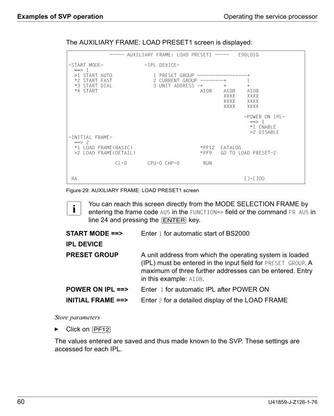
Examples of SVP operation Operating the service processor
60 U41859-J-Z126-1-76
The AUXILIARY FRAME: LOAD PRESET1 screen is displayed:
Figure 29: AUXILIARY FRAME: LOAD PRESET1 screen
i You can reach this screen directly from the MODE SELECTION FRAME by entering the frame code AU5 in the FUNCTION=> field or the command FR AU5 in line 24 and pressing the [ENTER] key.
Store parameters
Ê Click on [PF12]
The values entered are saved and thus made known to the SVP. These settings are accessed for each IPL.
START MODE ==> Enter 1 for automatic start of BS2000
IPL DEVICE
PRESET GROUP A unit address from which the operating system is loaded (IPL) must be entered in the input field for PRESET GROUP. A maximum of three further addresses can be entered. Entry in this example: A108.
POWER ON IPL ==> Enter 1 for automatic IPL after POWER ON
INITIAL FRAME ==> Enter 2 for a detailed display of the LOAD FRAME
----- AUXILIARY FRAME: LOAD PRESET1 ----- E90L01G
-START MODE- -IPL DEVICE- ==> 1 >1 START AUTO 1 PRESET GROUP -----------------+ *2 START FAST 2 CURRENT GROUP --------+ | *3 START DIAL 3 UNIT ADDRESS -+ + + *4 START A108 A108 A108 XXXX XXXX XXXX XXXX XXXX XXXX
-POWER ON IPL- ==> 1 *1 ENABLE >2 DISABLE-INITIAL FRAME- ==> 2 *1 LOAD FRAME(BASIC) *PF12 CATALOG >2 LOAD FRAME(DETAIL) *PF9 GO TO LOAD PRESET-2
CL-0 CPU-0 CHP-0 RUN RA []-[]00

Operating the service processor Examples of SVP operation
U41859-J-Z126-1-76 61
Dok
usch
abl
onen
19x
24 V
ers
ion
7.4
us fü
r F
ram
eM
aker
V7
.xvo
m 0
9.02
.201
0©
cog
nita
s G
mbH
200
1-2
010
Dok
usch
ablo
nen
19x2
4 V
ersi
on
7.4u
s fü
r F
ram
eM
aker
V7
.xvo
m 0
9.0
2.20
10©
cog
nita
s G
mb
H 2
001
-20
1026
. Ju
ne 2
015
Sta
nd
10:2
0.05
Pfa
d: P
:\FT
S-B
S\S
erve
r\S
E-S
erve
r\S
E-D
oku
\130
3907
_B
A_
SU
_39
0\p
rod_
e\ba
_su
390.
k05
4.5.4 Setting up PROGRAM LOAD FRAME PRESET2
In the PROGRAM LOAD FRAME PRESET2 you specify which operating mode is to be set after the server is switched on.
The following are specified in the example below:
● VM2000 operating mode
● Automatic startup of the operating system
Requirement
You are in the AUXILIARY FRAME: LOAD PRESET1.
Invoke the AUXILIARY FRAME: LOAD PRESET2 screen
Ê Click on [PF9].
The AUXILIARY FRAME: LOAD PRESET2 screen is displayed:
Figure 30: AUXILIARY FRAME: LOAD PRESET2 screen
VM MODE ==> Enter 2 for VM2000 operation
START IPL NO ==> Always enter 1 for automatic startup
----- AUXILIARY FRAME: LOAD PRESET2 ----- E90L01G
-VM MODE- ==> 2 >1 NATIVE *2 AVM/EX
-START IPL NO- ==> 1 >1 FIX(1) *2 CURRENT
*PF12 CATALOG *PF9 GO TO LOAD PRESET-1
CL-0 CPU-0 CHP-0 RUN RA []-[]00

Examples of SVP operation Operating the service processor
62 U41859-J-Z126-1-76
Store parameters
Ê Click on [PF12]
The values entered are saved and thus made known to the SVP. These settings are accessed for each IPL.
4.5.5 Executing IPL in PROGRAM LOAD FRAME: DETAIL-1
The IPL can be executed manually according to the setting using PROGRAM LOAD FRAME DETAIL-1.
The following are specified in the example below:
● loading VM2000
● dialog startup
● IPL device is specified manually by the entry of the unit address (here: loading the VM2000 from a device with the unit address A108)
Requirement
You are in the AUXILIARY FRAME: LOAD PRESET2 screen.
Invoke the PROGRAM LOAD FRAME: DETAIL-1 screen
Ê Click on [ModSel] to return to the MODE SELECTION FRAME.
Ê Enter the frame code LD and press the [ENTER] key. Or enter the FR LD command in line 24 and press the [ENTER] key.
i After entering LD or FR LD in the MODE SELECTION FRAME, depending on the INITIAL FRAME setting in the AUXILIARY FRAME: LOAD PRESET1 screen (see page 60) either the PROGRAM LOAD FRAME: DETAIL-1 screen or the PROGRAM LOAD FRAME: BASIC is displayed.
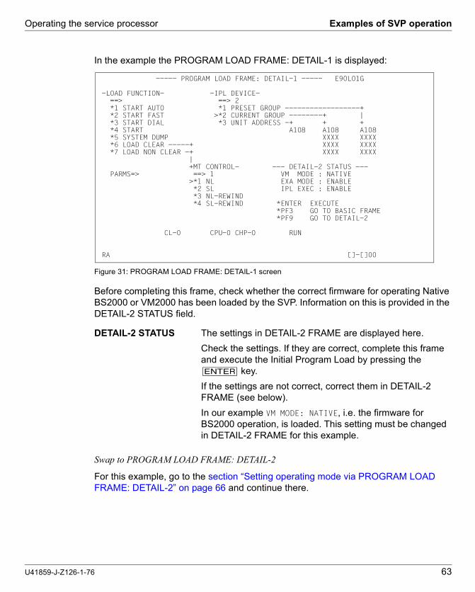
Operating the service processor Examples of SVP operation
U41859-J-Z126-1-76 63
Dok
usch
abl
onen
19x
24 V
ers
ion
7.4
us fü
r F
ram
eM
aker
V7
.xvo
m 0
9.02
.201
0©
cog
nita
s G
mbH
200
1-2
010
Dok
usch
ablo
nen
19x2
4 V
ersi
on
7.4u
s fü
r F
ram
eM
aker
V7
.xvo
m 0
9.0
2.20
10©
cog
nita
s G
mb
H 2
001
-20
1026
. Ju
ne 2
015
Sta
nd
10:2
0.05
Pfa
d: P
:\FT
S-B
S\S
erve
r\S
E-S
erve
r\S
E-D
oku
\130
3907
_B
A_
SU
_39
0\p
rod_
e\ba
_su
390.
k05
In the example the PROGRAM LOAD FRAME: DETAIL-1 is displayed:
Figure 31: PROGRAM LOAD FRAME: DETAIL-1 screen
Before completing this frame, check whether the correct firmware for operating Native BS2000 or VM2000 has been loaded by the SVP. Information on this is provided in the DETAIL-2 STATUS field.
Swap to PROGRAM LOAD FRAME: DETAIL-2
For this example, go to the section “Setting operating mode via PROGRAM LOAD FRAME: DETAIL-2” on page 66 and continue there.
DETAIL-2 STATUS The settings in DETAIL-2 FRAME are displayed here.
Check the settings. If they are correct, complete this frame and execute the Initial Program Load by pressing the [ENTER] key.
If the settings are not correct, correct them in DETAIL-2 FRAME (see below).
In our example VM MODE: NATIVE, i.e. the firmware for BS2000 operation, is loaded. This setting must be changed in DETAIL-2 FRAME for this example.
----- PROGRAM LOAD FRAME: DETAIL-1 ----- E90L01G
-LOAD FUNCTION- -IPL DEVICE- ==> ==> 2 *1 START AUTO *1 PRESET GROUP ------------------+ *2 START FAST >*2 CURRENT GROUP --------+ | *3 START DIAL *3 UNIT ADDRESS -+ + + *4 START A108 A108 A108 *5 SYSTEM DUMP XXXX XXXX *6 LOAD CLEAR -----+ XXXX XXXX *7 LOAD NON CLEAR -+ XXXX XXXX | +MT CONTROL- --- DETAIL-2 STATUS --- PARMS=> ==> 1 VM MODE : NATIVE >*1 NL EXA MODE : ENABLE *2 SL IPL EXEC : ENABLE *3 NL-REWIND *4 SL-REWIND *ENTER EXECUTE *PF3 GO TO BASIC FRAME *PF9 GO TO DETAIL-2
CL-0 CPU-0 CHP-0 RUN RA []-[]00

Examples of SVP operation Operating the service processor
64 U41859-J-Z126-1-76
If the DETAIL-2 STATUS is correct, fill in the entry fields as follows:
Figure 32: PROGRAM LOAD FRAME: DETAIL-1 screen
LOAD FUNCTION ==> Enter 3 for a dialog start
IPL DEVICE ==> Enter 3 for entry of a device address
UNIT ADDRESS The device address of the load device can be entered in this field
In this example, the previous IPL was executed successfully from the current device with device address A108. Thus the desired address is already in the UNIT ADDRESS field. It was also entered in the CURRENT GROUP field by the SVP. Entering a 2 in the IPL DEVICE field loads the operating system from the desired device.
PARMS => Enter 1 in the first position of the field to load VM2000
MT CONTROL ==> 1 is the default. This parameter is only important for loading from tape.
----- PROGRAM LOAD FRAME: DETAIL-1 ----- E90L01G
-LOAD FUNCTION- -IPL DEVICE- ==> 3 ==> 3 *1 START AUTO *1 PRESET GROUP ------------------+ *2 START FAST >*2 CURRENT GROUP --------+ | *3 START DIAL *3 UNIT ADDRESS -+ + + *4 START A108 A108 A108 *5 SYSTEM DUMP XXXX XXXX *6 LOAD CLEAR -----+ XXXX XXXX *7 LOAD NON CLEAR -+ XXXX XXXX | +MT CONTROL- --- DETAIL-2 STATUS --- PARMS=> 1 ==> 1 VM MODE : AVM/EX >*1 NL EXA MODE : ENABLE *2 SL IPL EXEC : ENABLE *3 NL-REWIND *4 SL-REWIND *ENTER EXECUTE *PF3 GO TO BASIC FRAME *PF9 GO TO DETAIL-2
CL-0 CPU-0 CHP-0 RUN RA []-[]00

Operating the service processor Examples of SVP operation
U41859-J-Z126-1-76 65
Dok
usch
abl
onen
19x
24 V
ers
ion
7.4
us fü
r F
ram
eM
aker
V7
.xvo
m 0
9.02
.201
0©
cog
nita
s G
mbH
200
1-2
010
Dok
usch
ablo
nen
19x2
4 V
ersi
on
7.4u
s fü
r F
ram
eM
aker
V7
.xvo
m 0
9.0
2.20
10©
cog
nita
s G
mb
H 2
001
-20
1026
. Ju
ne 2
015
Sta
nd
10:2
0.05
Pfa
d: P
:\FT
S-B
S\S
erve
r\S
E-S
erve
r\S
E-D
oku
\130
3907
_B
A_
SU
_39
0\p
rod_
e\ba
_su
390.
k05
executes IPL
Ê Press the [[ENTER] key after you have checked all the settings.
The following prompt appears on the screen:
v CAUTION! The IPL must not be executed during system operation! If this instruction is not heeded, BS2000 will be aborted!
Ê Press the [Y] key to execute the IPL, or the [N] key to cancel the procedure. Confirm your entry with the [ENTER] key.
************************************ ** ARE YOU SURE ? (ENTER Y OR N) N ** ************************************

Examples of SVP operation Operating the service processor
66 U41859-J-Z126-1-76
4.5.6 Setting operating mode via PROGRAM LOAD FRAME: DETAIL-2
The operating mode can be set anew according to the setting using PROGRAM LOAD FRAME: DETAIL-2. This selects the appropriate firmware for running BS2000 or VM2000.
The following are specified in the example below:
● VM2000 operating mode
● executing IPL after reloading the firmware
Requirement
You are in the PROGRAM LOAD FRAME: DETAIL-1 screen.
Invoke the PROGRAM LOAD FRAME: DETAIL-2 screen
Ê Click on [PF9]
The PROGRAM LOAD FRAME: DETAIL-2 screen is displayed:
Figure 33: PROGRAM LOAD FRAME: DETAIL-2 screen
VM MODE ==> Enter 2 for VM2000 operation
IPL EXECUTION ==> Enter 1 for executing IPL
----- PROGRAM LOAD FRAME: DETAIL-2 ----- E90L01G
-VM MODE- -IPL EXECUTION- ==> 2 ==> 1>*1 NATIVE >*1 ENABLE*2 AVM/EX *2 DISABLE
*ENTER EXECUTE *PF3 GO TO BASIC FRAME *PF9 GO TO DETAIL-1
CL-0 CPU-0 CHP-0 RUN RA []-[]00

Operating the service processor Examples of SVP operation
U41859-J-Z126-1-76 67
Dok
usch
abl
onen
19x
24 V
ers
ion
7.4
us fü
r F
ram
eM
aker
V7
.xvo
m 0
9.02
.201
0©
cog
nita
s G
mbH
200
1-2
010
Dok
usch
ablo
nen
19x2
4 V
ersi
on
7.4u
s fü
r F
ram
eM
aker
V7
.xvo
m 0
9.0
2.20
10©
cog
nita
s G
mb
H 2
001
-20
1026
. Ju
ne 2
015
Sta
nd
10:2
0.05
Pfa
d: P
:\FT
S-B
S\S
erve
r\S
E-S
erve
r\S
E-D
oku
\130
3907
_B
A_
SU
_39
0\p
rod_
e\ba
_su
390.
k05
Storing settings
Ê After you have checked all the settings, click on [PF9] to store them and to switch to PROGRAM LOAD FRAME: DETAIL-1.
The new setting is displayed under VM MODE: in the DETAIL-2 STATUS field. VM MODE: AVM/EX is now displayed. The firmware is relocated before the IPL is executed.
By filling PROGRAM LOAD FRAME: DETAIL-1 and pressing the [ENTER] you can execute the IPL (see page 64).
Make sure you fill in the PARMS field correctly.

Examples of SVP operation Operating the service processor
68 U41859-J-Z126-1-76

U41859-J-Z126-1-76 69
Dok
usch
abl
onen
19x
24 V
ers
ion
7.4
us fü
r F
ram
eM
aker
V7
.xvo
m 0
9.02
.201
0©
cog
nita
s G
mbH
200
1-2
010
Dok
usch
ablo
nen
19x2
4 V
ersi
on
7.4u
s fü
r F
ram
eM
aker
V7
.xvo
m 0
9.0
2.20
10©
cog
nita
s G
mb
H 2
001
-20
1025
. Ju
ne 2
015
Sta
nd
15:3
1.16
Pfa
d: P
:\FT
S-B
S\S
erve
r\S
E-S
erve
r\S
E-D
oku
\130
3907
_B
A_
SU
_39
0\p
rod_
e\ba
_su
390.
k06
5 HNC (High Speed Net Connect)
The High Speed Network Connect (HNC for short) connects the Server Unit /390 to the LAN. Furthermore, as net client the HNC permits access to the Net-Storage. The HNC is operated and managed using the SE Manager.
The internal disks, power supply units, and fans are redundant in design and can be replaced during ongoing operation.
The rack console serves as a monitor for the Management Unit and consequently as a local access administrative and operating functions of the SE server. When necessary (in the event of maintenance), the rack console can also be attached to the HNC using the KVM switch.
The HNC software is preinstalled ex works.
HNC redundancy is possible as an option. Up to four HNCs can be integrated.
Detailed information on operating the HNC is provided in the "Operation and Adminis-tration" manual [7].
Detailed information on the various hardware components and interfaces of the HNC is provided in the data sheet "FUJITSU Server BS2000 SE Series". See the product site for the relevant server at http://www.fujitsu.com/de:
Ê Go to Products → Servers → BS2000 → FUJITSU Server BS2000 and select SE700 or SE500.
Figure 34: HNC - front
Figure 35: HNC - rear
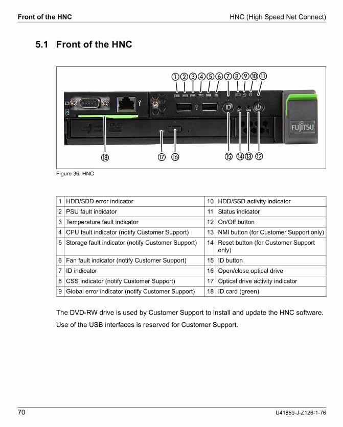
Front of the HNC HNC (High Speed Net Connect)
70 U41859-J-Z126-1-76
5.1 Front of the HNC
Figure 36: HNC
The DVD-RW drive is used by Customer Support to install and update the HNC software.
Use of the USB interfaces is reserved for Customer Support.
1 HDD/SDD error indicator 10 HDD/SSD activity indicator
2 PSU fault indicator 11 Status indicator
3 Temperature fault indicator 12 On/Off button
4 CPU fault indicator (notify Customer Support) 13 NMI button (for Customer Support only)
5 Storage fault indicator (notify Customer Support) 14 Reset button (for Customer Support only)
6 Fan fault indicator (notify Customer Support) 15 ID button
7 ID indicator 16 Open/close optical drive
8 CSS indicator (notify Customer Support) 17 Optical drive activity indicator
9 Global error indicator (notify Customer Support) 18 ID card (green)
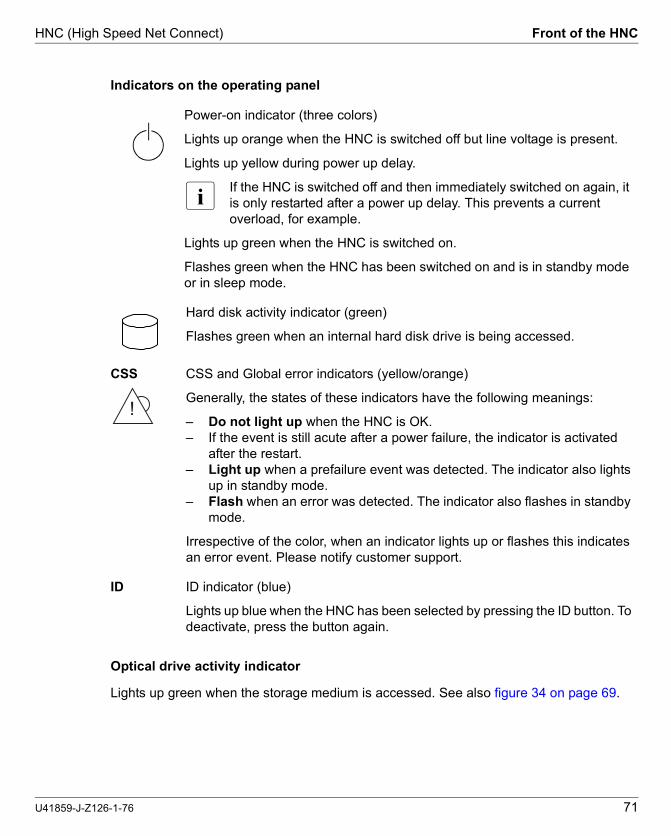
HNC (High Speed Net Connect) Front of the HNC
U41859-J-Z126-1-76 71
Dok
usch
abl
onen
19x
24 V
ers
ion
7.4
us fü
r F
ram
eM
aker
V7
.xvo
m 0
9.02
.201
0©
cog
nita
s G
mbH
200
1-2
010
Dok
usch
ablo
nen
19x2
4 V
ersi
on
7.4u
s fü
r F
ram
eM
aker
V7
.xvo
m 0
9.0
2.20
10©
cog
nita
s G
mb
H 2
001
-20
1025
. Ju
ne 2
015
Sta
nd
15:3
1.16
Pfa
d: P
:\FT
S-B
S\S
erve
r\S
E-S
erve
r\S
E-D
oku
\130
3907
_B
A_
SU
_39
0\p
rod_
e\ba
_su
390.
k06
Indicators on the operating panel
Optical drive activity indicator
Lights up green when the storage medium is accessed. See also figure 34 on page 69.
Power-on indicator (three colors)
Lights up orange when the HNC is switched off but line voltage is present.
Lights up yellow during power up delay.
I If the HNC is switched off and then immediately switched on again, it is only restarted after a power up delay. This prevents a current overload, for example.
Lights up green when the HNC is switched on.
Flashes green when the HNC has been switched on and is in standby mode or in sleep mode.
Hard disk activity indicator (green)
Flashes green when an internal hard disk drive is being accessed.
CSS CSS and Global error indicators (yellow/orange)
Generally, the states of these indicators have the following meanings:
– Do not light up when the HNC is OK.– If the event is still acute after a power failure, the indicator is activated
after the restart.– Light up when a prefailure event was detected. The indicator also lights
up in standby mode.– Flash when an error was detected. The indicator also flashes in standby
mode.
Irrespective of the color, when an indicator lights up or flashes this indicates an error event. Please notify customer support.
ID ID indicator (blue)
Lights up blue when the HNC has been selected by pressing the ID button. To deactivate, press the button again.
!

Front of the HNC HNC (High Speed Net Connect)
72 U41859-J-Z126-1-76
Hard disk drive control indicators
Figure 37: Front - Detailed view: Indicators on a hard disk module
1 HDD BUSY (green)
– Lights up: HDD in active phase– Does not light up: HDD inactive
2 HDD FAULT (orange) (in conjunction with a RAID controller)
– Does not light up: no HDD error– Lights up: HDD Faulty or Rebuild Stopped (drive defective, needs replacing, a rebuild
process was stopped or the HDD module is not correctly inserted)– Slow flashing: HDD Rebuild (the data is being restored after changing a hard disk drive)– Fast flashing: HDD Identify– Four fast flashes/pause: HDD Predicted Fault– Two fast flashes/pause: HDD Hot Spare (The corresponding drive has failed).

HNC (High Speed Net Connect) Rear of the HNC
U41859-J-Z126-1-76 73
Dok
usch
abl
onen
19x
24 V
ers
ion
7.4
us fü
r F
ram
eM
aker
V7
.xvo
m 0
9.02
.201
0©
cog
nita
s G
mbH
200
1-2
010
Dok
usch
ablo
nen
19x2
4 V
ersi
on
7.4u
s fü
r F
ram
eM
aker
V7
.xvo
m 0
9.0
2.20
10©
cog
nita
s G
mb
H 2
001
-20
1025
. Ju
ne 2
015
Sta
nd
15:3
1.16
Pfa
d: P
:\FT
S-B
S\S
erve
r\S
E-S
erve
r\S
E-D
oku
\130
3907
_B
A_
SU
_39
0\p
rod_
e\ba
_su
390.
k06
5.2 Rear of the HNC
ID/CSS/Global error indicator
Figure 38: ID/CSS/Global error indicator
1 ID/CSS/Global error indicator
ID ID indicator (blue)
Lights up blue when the HNC has been selected by pressing the ID button. To deactivate, press the button again.
CSS CSS and Global error indicator (yellow/orange)
Generally, the states of these indicators have the following meanings:
– Do not light up when the HNC is OK.– If the event is still acute after a power failure, the indicator is activated after
the restart.– Light up when a prefailure event was detected. The indicator also lights
up in standby mode.– Flash when an error was detected. The indicator also flashes in standby
mode.
Irrespective of the color, when an indicator lights up or flashes this indicates an error event. Please notify customer support.
!

Rear of the HNC HNC (High Speed Net Connect)
74 U41859-J-Z126-1-76
LAN indicators
Figure 39: LAN indicators
1 LAN activity indicator
Lights up green if a LAN connection exists.Does not light up if no LAN connection exists.Flashes green when a LAN transfer is in progress.
2 LAN speed indicator
Lights up yellow for a LAN transfer rate of 1 Gbps.Lights up green for a LAN transfer rate of 100 Mbps.Does not light up for a LAN transfer rate of 10 Mbps.
(System-LAN-Ports)
SYS1 SYS2 ungenutzt

HNC (High Speed Net Connect) Rear of the HNC
U41859-J-Z126-1-76 75
Dok
usch
abl
onen
19x
24 V
ers
ion
7.4
us fü
r F
ram
eM
aker
V7
.xvo
m 0
9.02
.201
0©
cog
nita
s G
mbH
200
1-2
010
Dok
usch
ablo
nen
19x2
4 V
ersi
on
7.4u
s fü
r F
ram
eM
aker
V7
.xvo
m 0
9.0
2.20
10©
cog
nita
s G
mb
H 2
001
-20
1025
. Ju
ne 2
015
Sta
nd
15:3
1.16
Pfa
d: P
:\FT
S-B
S\S
erve
r\S
E-S
erve
r\S
E-D
oku
\130
3907
_B
A_
SU
_39
0\p
rod_
e\ba
_su
390.
k06
Indicator on hot-plug power supply unit
Figure 40: Indicator on hot-plug power supply unit
1) The following events are detected as predictable errors:– The temperature is very high.– The power consumption is very high.– The current strength is very high.– The fan speed is very low.In each of these cases please notify Customer Support.
1 Indicator on hot-plug power supply unit (two colors)
Flashes green when the HNC is switched off, but line voltage is present (standby mode).
Lights up green when the HNC is switched on and functioning properly.
Flashes orange when a predictable error has been detected, but the power supply unit is still running. 1)
Lights up orange when no line voltage is present or the power supply unit has failed.

Rear of the HNC HNC (High Speed Net Connect)
76 U41859-J-Z126-1-76
Assignment of the PCIe slots
Figure 41: Principle of PCIe slot assignment at the rear of the device
The figure shows the PCIe slots of the HNC:
PCIe slot Assignment
S1 Not assigned; an optical LAN card is optionally possible
S2 4-port LAN card
S3 FibreChannel card
Table 2: PCIe slot assignment on an HNC
S3 S1
(System LAN ports)SYS1 SYS2 USB ports
S2

U41859-J-Z126-1-76 77
Dok
usch
abl
onen
19x
24 V
ers
ion
7.4
us fü
r F
ram
eM
aker
V7
.xvo
m 0
9.02
.201
0©
cog
nita
s G
mbH
200
1-2
010
Dok
usch
ablo
nen
19x2
4 V
ersi
on
7.4u
s fü
r F
ram
eM
aker
V7
.xvo
m 0
9.0
2.20
10©
cog
nita
s G
mb
H 2
001
-20
1025
. Ju
ne 2
015
Sta
nd
15:3
1.16
Pfa
d: P
:\FT
S-B
S\S
erve
r\S
E-S
erve
r\S
E-D
oku
\130
3907
_B
A_
SU
_39
0\p
rod_
e\ba
_su
390.
k09
6 What to do if ...
In this chapter you are told how the Server Unit informs you of how you perform a system dump when inexplicable system downtime occurs.
In the event of hardware faults the operating system will take the necessary recovery action autonomously. Customer Service is automatically informed by means of a ServiceCall and initiates repair measures, possibly in conjunction with the customer.
6.1 Indicators when a hardware fault occurs
The server informs you of hardware faults in the following manner:
● On the server's control panel
When the yellow CHECK lamp lights up, this can signal a hardware fault. At the same time the status indicator displays the FLAG code. This can mean a fault in the service processor or a hardware malfunction.
● In the SVP console window
On the SVP console, indicators in row 24 of the SVP frame can signal a hardware fault. Evaluation of the FLAG code is reserved for Customer Support. The figure below shows the format of the display:
Figure 42: Status display in rows 24 and 25 of the SVP console
FLAG code FF . . . FF can have different meanings and consequently require different responses:
– A WRITE-CONSOLE message has been displayed. This can be deleted with [ModSel]. This does not delete the FLAG code indicator.
ccccccccccccccccccccccccccccccccccccccccccccccccccccccc FLAG CODE = FFFFFFFF FFFFFFFF RA []-[]00

Performing a system dump What to do if ...
78 U41859-J-Z126-1-76
– A warning has been displayed, e.g. when the room temperature is too high. The cause of the fault must be rectified. System operation can continue in the meantime.
– A fault which has automatically been corrected by the hardware occurred on the server or at the interface to the peripheral devices. In this case, too, system operation can continue.
– A fault has occurred which does not permit system operation to continue. In this case you can respond as follows:
When system downtime occurs, perform an MPL. If this does not rectify the fault, notify Customer Support and discuss how to proceed further.
6.2 Performing a system dump
Requirement:
SVP console opened and ready
1. Select (LD) PROGRAM LOAD FRAME
2. Select LOAD FUNCTION => 5 (SYSTEM DUMP)
The memory dump stored by the DUMP program to disk or tape is required for error diagnosis.
The BS2000/VM2000 system must subsequently be reloaded by means of IPL.
i Information on SLED operation is provided in the "Introduction to System Adminis-tration" manual [8].

U41859-J-Z126-1-76 79
Dok
usch
abl
onen
19x
24 V
ers
ion
7.4
de f
ür F
ram
eM
aker
V7.
xvo
m 0
9.0
2.20
10©
cog
nita
s G
mb
H 2
001
-20
102
5. J
une
201
5 S
tan
d 15
:31.
15P
fad:
P:\
FT
S-B
S\S
erve
r\S
E-S
erve
r\S
E-D
oku
\130
390
7_B
A_
SU
_39
0\p
rod_
e\b
a_su
390
.lit
Related publications
You will find the manuals on the internet at http://manuals.ts.fujitsu.com. You can order printed versions of manuals which are displayed with the order number.
[1] FUJITSU Server BS2000 SE700 / SE500 / SE300Basic Operating Manual
[2] FUJITSU Server BS2000 SE700 / SE500 Server Unit /390
[3] FUJITSU Server BS2000 SE700 / SE500 / SE300Server Unit x86
[4] FUJITSU Server BS2000 SE700 / SE500 / SE300Additive Components
[5] FUJITSU Server BS2000 SE Series Security Manual User Guide
[6] FUJITSU Server BS2000 SE Series Quick Guide User Guide
[7] FUJITSU Server BS2000 SE Series Operation and AdministrationUser Guide
[8] BS2000 OSD/BC V10.0 Introduction to System Administration (SE Server)User Guide

Related publications
80 U41859-J-Z126-1-76

U41859-J-Z126-1-76 81
Dok
usch
abl
onen
19x
24 V
ers
ion
7.4
de f
ür F
ram
eM
aker
V7.
xvo
m 0
9.0
2.20
10©
cog
nita
s G
mb
H 2
001
-20
1026
. Jun
e 2
015
Sta
nd 1
0:2
0.05
Pfa
d: P
:\FT
S-B
S\S
erve
r\S
E-S
erve
r\S
E-D
oku\
1303
907
_BA
_SU
_39
0\pr
od_
e\ba
_su3
90.
six
Index
AALTER/DISPLAY FRAME (AD) 37ALTER/DISPLAY FRAME (subframe) 39AUTO (automatic startup) 59AUXILIARY FRAME
IORSF CONTROL 57LOAD PRESET1 60LOAD PRESET2 61MENU 56MENU (AU) 42, 44P-OFF/IMPL 58
AUXILIARY FRAME (AU1): REAL CLOCK 45AUXILIARY FRAME (AU2): IORSF
CONTROL 46AUXILIARY FRAME (AU3): RELATED SCB’S (for
Customer Support only) 48AUXILIARY FRAME (AU4): POWER STAND-BY/
IMPL 49AUXILIARY FRAME (AU5): LOAD PRESET1 50AUXILIARY FRAME (AU5): LOAD PRESET2 52
BBS2000, loading 11
CCH/SUBCH STATUS DISPLAY FRAME:
CHANNEL 41channel box 8, 10CHE box 8, 10code, frame 22CPU fault indicator 70CPU register, display/change content 39CSS indicator 70, 73
Ddata sheet 69display 17
hardware status 17DVD drive activity, indicator 70, 71
Eexecuting IPL in DETAIL-1 FRAME 62
FFLAG code 17frame 24frame code 22frame name 22
GGlobal error indicator 70, 71, 73Global error indicators 73
Hhardware fault, indicator 77hardware status, display 17HDD BUSY 72HDD FAULT 72HDD/SDD activity, indicator 70HDD/SDD error indicator 70
IID button 70ID indicator 70, 71, 73

Index
82 U41859-J-Z126-1-76
indicatorsCPU fault 70CSS 70, 73DVD drive activity 70, 71Global error 70, 73hard disk activity 71hardware fault 77HDD/SDD activity 70HDD/SDD error 70ID 70, 73operating status indicator 70PSU error 70storage fault 70temperature fault 70
IORSFload 55select 11, 55
IPLexecuting in DETAIL-1 FRAME 62manual 62
Lloading
BS2000 11IORSF 55
Mmanual IPL 62MANUAL OPERATION FRAME (MA) 35messages 15MODE SELECTION FRAME (ML) 24, 55MSF FRAME (MF) 53
NNMI button 70
Ooperating frames 19operating mode 61
setting 66operating status indicator 70
PPERFORMANCE ANALYZER FRAME (PA) 54power button 70power supply unit 75power-on indicator 71PROGRAM LOAD FRAME
BASIC (LD) 27DETAIL-1 28, 63, 64DETAIL-2 32, 66PRESET1 set up 59PRESET2 einrichten 61
PSU error indicator 70PSW (Program Status Word) 15
RReset button 70
Sscreen
AUXILIARY FRAME IORSF CONTROL 57AUXILIARY FRAME LOAD PRESET1 60AUXILIARY FRAME LOAD PRESET2 61AUXILIARY FRAME MENU 56AUXILIARY FRAME POWER STAND-BY/
IMPL 58MODE SELECTION FRAME 24, 55PROGRAM LOAD FRAME 63, 64
selectingIORSF 55
Server Unit /390 7, 9setting operating mode 66setting up
PROGRAM LOAD FRAME PRESET1 59PROGRAM LOAD FRAME PRESET2 61
starting IMPL 11STATUS DISPLAY FRAME (ST) 34storage fault indicator 70SU700 7, 9subframes 24SVP
buttons 19display 17messages 15

Index
U41859-J-Z126-1-76 83
Dok
usch
abl
onen
19x
24 V
ers
ion
7.4
de f
ür F
ram
eM
aker
V7.
xvo
m 0
9.0
2.20
10©
cog
nita
s G
mb
H 2
001
-20
1026
. Jun
e 2
015
Sta
nd 1
0:2
0.05
Pfa
d: P
:\FT
S-B
S\S
erve
r\S
E-S
erve
r\S
E-D
oku\
1303
907
_BA
_SU
_39
0\pr
od_
e\ba
_su3
90.
six
system dump, performing 78system status messages 16
Ttemperature fault indicator 70

Index
84 U41859-J-Z126-1-76