se5 ian firth- j sutherland lecture 2010:layout 3 · the circumstances surrounding the failure...
TRANSCRIPT
18 The Structural Engineer 88 (5) 2 March 2010
Synopsis
For many engineers, the steel box girder story starts with disaster.The memories of the tragic events of 1970 and 1971 are still rawfor some, and the implications have been far reaching. But thestory is also one of bold innovation, lessons learnt and ultimatesuccess. This paper explores the short history of the steel boxgirder and reflects on how it has shaped the evolution of thepopular modern bridge structures we see today.
Acknowledgment
As a student at Bristol University in 1977, I undertook a study intothe circumstances surrounding the failure during erection of thesteel box girder bridge over the Yarra River in Melbourne. I didn’tknow then that I would join Flint & Neill upon graduation or that Iwould eventually be asked to deliver the James Sutherland HistoryLecture on the subject of steel box girders. Had I known, no doubtI would have paid more attention!
Although I am honoured to be asked to tell this story, I mustpoint out that it is not really mine to tell. It belongs to the truly greatengineers in whose footsteps I have had the honour and goodfortune to tread. Most of the history I will attempt to relate isrelatively recent, and I am acutely aware that some of those greatengineers who were directly involved in this ground breaking work,making significant advances in this field, are still alive today. I musttherefore beg their forgiveness for any inaccuracy or omission inmy account, and ask that they use the discussion that I hope willfollow the delivery of this paper to correct my errors.
In particular, I wish to acknowledge the enormous contribution
made by my colleagues and former Partners at Flint & Neill, TonyFlint, Brian Smith and John Evans, who have been my mentorsand teachers through the years, as well as the many tutors on thissubject too numerous to mention at Bristol University andsubsequently Imperial College in London. I am also grateful toHolger Svensson and Siegfried Hopf of Leonhardt Andrä undPartner for providing information on some of the post-wardevelopments in Germany which are a significant part of this story.
Introduction
Engineering history is the story of learning from failure. Withoutfailure technology stagnates. It is necessary to try something newfrom time to time, and then history allows us to judge whether it isa success or not. The best innovations are repeated and improvedupon while others tend to fade away. Some early box girderinnovations clearly stretched the boundaries a bit too far, but thelessons were learnt and subsequent generations have benefittedas a result.
In the decades immediately after the Second World War,economic circumstances and the drive to build new roads led tothe need to find more and more efficient ways of building bridges.In Germany, many new bridges were called for, including severalacross the Rhine and other large rivers. The story goes that theLuftwaffe engineers, prevented for a while from building newaircraft, applied their skills to the re-construction effort. This wouldnot be the first time that ideas from other industries foundapplication in construction; in this case a familiar lightweighttubular form of fuselage turned into a bridge beam. Whether or notthis is the real origin of the modern steel box girder (after all theefficiency of box structures was already well known) there is littledoubt that innovative designs for box girder bridges using thinstiffened steel plate began to appear on drawing boards in the late1940s.
But before we get on to the story of modern steel box girders, itis worth pausing to consider their predecessors.
Early history
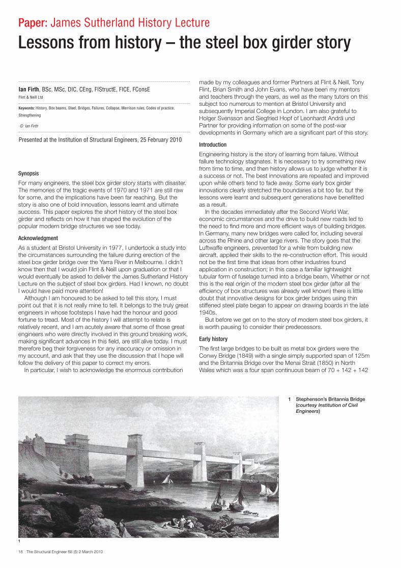
The first large bridges to be built as metal box girders were theConwy Bridge (1849) with a single simply supported span of 125mand the Britannia Bridge over the Menai Strait (1850) in NorthWales which was a four span continuous beam of 70 + 142 + 142
Paper: James Sutherland History Lecture
Lessons from history – the steel box girder story
Ian Firth, BSc, MSc, DIC, CEng, FIStructE, FICE, FConsEFlint & Neill Ltd
Keywords: History, Box beams, Steel, Bridges, Failures, Collapse, Merrison rules, Codes of practice,
Strengthening
© Ian Firth
Presented at the Institution of Structural Engineers, 25 February 2010
1 Stephenson’s Britannia Bridge (courtesy Institution of Civil Engineers)
1
SE5 Ian Firth- J Sutherland Lecture 2010:Layout 3 24/2/10 14:59 Page 18
The Structural Engineer 88 (5) 2 March 2010 19
+ 70m (Fig 1). Both were constructed in wrought iron and bothwere designed by Robert Stephenson, the son of the steamengine inventor.
These bridges carried steam trains which travelled through theinside of the rectangular box girder which therefore could not haveinternal transverse diaphragms to stiffen the box walls andmaintain its shape. This worked because each box only carried asingle rail track so torsion and distortion effects were small. Thesebridges were a huge breakthrough and a significant innovation.Not only was this the first time wrought iron had been used in alarge bridge structure, it was also the first use of a large closedbox with thin plate walls. Furthermore, the Britannia boxes werebuilt on dry land and floated out to be lifted into position ascomplete spans – a technique that is still commonly used today.Sadly, the Britannia box beams were destroyed by fire in 1970.The bridge was reconstructed with arches to support a new steeldeck structure which now carries the trains plus a new road on itsupper level.
Before the advent of wrought iron in the form of large plates inthe mid-19th century, it was not possible to conceive of thin-walledplate or box girder structures, but this material enableddevelopments in this technology, such as for the oval sectionarches on Brunel’s Royal Albert Bridge in Saltash (1859). By theend of the 19th century, steel plate had become available followingthe invention of the Bessemer process (1856) and then theSiemens-Martin process (1865), and this enabled the constructionof one of the earliest great steel bridges which had hollow boxsection components – the Forth railway bridge in Scotland (1890).
However, Saltash and Forth cannot really be called box girderbridges, even though their primary structural members are madeof large thin walled tubes, and it was not for many years that truebox girders began to emerge. Apart from Stephenson’s innovative
intervention in the mid-19th century, very few metal girder bridgesadopted a closed box form, preferring instead to stick with themore familiar truss form of construction. Indeed, it is not until themid-20th century, 100 years later, that steel box girders begin tocome into their own, and this is largely because of the method ofjoining the plates together.
A new jointing technology and the birth of the modern steel box girder
By far the most common method for joining metal plates togetherin the late 19th and early 20th century was by riveting. Bolting wasalso used, but these were not yet of the High Strength Friction Griptype, and bolts in clearance holes sometimes gave rise todifficulties due to joint movements. Rivets were therefore preferredbecause they provided an effectively rigid joint due to the clampingaction achieved as the hot rivet cooled after installation. However,riveting was also very costly, labour intensive, time consuming andhazardous, and a better method of joining plates was needed.
Modern arc welding technology developed during the 1920sand 1930s and after some early difficulties became established asa reliable method for joining steel plates in large constructions bythe 1940s. During the Second World War, welding began to beused for building ships, and after the war the Germans turned theirhand to the task of bridge reconstruction. In a drive to reduceweight and save material (brought about by acute steel shortages)Professor F. Leonhardt had been experimenting with orthotropicdecks and had developed techniques for their analysis. Theorthotropic deck was only made practicable by welding, and thisenabled weight savings and slender girders previously thoughtunachievable. Weight savings were also made possible by thedevelopment, around this same time, of higher strength steelmaterials.
Thus the modern slender steel box girder bridge was born, and
Table 1 Comparison of steel bridge girder weights (prior to upgrade)
Date Bridge TypeTrafficlanes
Mainspan(m)
Steel box weight
(t/m) (t/m/lane)
1939 Bronx-Whitestone Plate - suspension 6 701 17 2.8
1948 Cologne-Deutz Box - Girder 185
1957 MackinacTruss -suspension 4 1158 12.2 3.0
1957 Theodor Heuss Box – Cable stay 260
1964 Verrazano NarrowsTruss -suspension 12 1298 39.7 3.3
1964 ForthTruss -suspension 4 1006 8.0 2.0
1966 Severn Box - Suspension 4 988 7.1 1.8
1970 Little Belt Box - Suspension 6 600 12.8 2.1
1971 Erskine Box - Cable stay 4 305 7.4 1.9
1973 Bosporus 1 Box - Suspension 6 1074 8.2 1.4
1974 Avonmouth Box - Girder 6 174 8.2 1.4
1975 Cleddau Box - Girder 4 214 8.4 2.1
1981 Humber Box - Suspension 4 1410 5.1 1.3
1988 Bosporus 2 Box - Suspension 8 1090 12.8 1.6
1994 Normandy Box - Cable stay 4 856 10.4 2.6
1998Great Belt EastBridge Box - Suspension 4 1624 11.0 2.8
1998Great BeltApproaches Box - Girder 4 110 12.0 3.0
2009 Stonecutters Box - Cable stay 6 1013 29.1 4.9
2
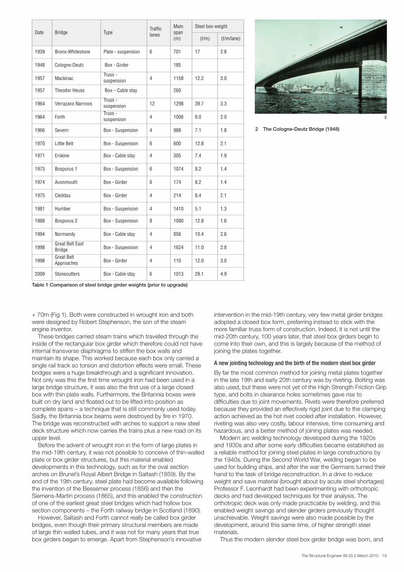
2 The Cologne-Deutz Bridge (1948)
SE5 Ian Firth- J Sutherland Lecture 2010:Layout 3 24/2/10 14:59 Page 19

20 The Structural Engineer 88 (5) 2 March 2010
it is generally considered that the first was the Cologne-DuetzBridge (1948) designed by Leonhardt1. With a main span of 185m,this three span steel box girder replaced an earlier plate girdersuspension bridge which had been bombed during the war. Thegirder had a depth over the piers of 7.8m (span/24) and 3.3m atmidspan (span/56), and although it had a stiffened steel top flange,it had a concrete slab added on top as the wearing road surface(Fig 2). Interestingly, the plates were connected by rivetting.
One of the great advantages of the box girder form is that therunning deck – the structural element on which vehicles actuallytravel – is integral with the main girder; i.e. the girder top flangeand the running deck are one and the same. Weights and costsreduced because it was no longer necessary to have a separatesecondary structure to support the deck independent of the mainprimary girder. Thus the development of the orthotropic deck plateand the steel box girder went hand in hand. The stiffenedorthotropic deck enabled the thin steel plate to carry heavy wheelloads without excessive local bending and distortion. Earlyversions used open stiffeners (flats, bulb flats and angles), but thenclosed trough stiffeners emerged to provide improved torsionalresistance and lateral distribution of local wheel load effects. Thebehaviour of the steel deck is closely tied to that of the roadwaysurfacing material, and developments in orthotropic deck designinvolved understanding the significance of this interaction (Table 1).However, this was not to be fully investigated until the late 1980swhen preparing to re-surface the Severn Crossing, as we shallsee.
In post war Britain, without Germany’s pressing need for bridgere-construction and with a national economy in crisis, the speed ofdevelopment was slower. Then in the 1950s, as part of a growingnational highway network, plans for long span bridges over theRivers Tamar, Severn and Forth began to develop. Initially, thesewere all conceived as suspension bridges (cable stayed bridgeconcepts having not yet evolved to maturity) with relativelyconventional steel truss girders. Indeed the Tamar (1961) and Forth(1964) bridges were constructed this way. Plans for truss girdersuspension bridges were also developing elsewhere at this time,such as Mackinac (1957), Verrazano Narrows (1964) and Tagus(1966).
But for Severn Bridge, circumstances conspired to produce arevolution which changed the shape of suspension bridges forever,and opened the door to radical technological developments which
continue today. However, to understand the significance of this wemust first turn the clock back to 1940 and consider theimportance of aerodynamic stability for long spans.
The Tacoma legacy
Any history of steel box girders would not be complete withouttouching on the collapse of Tacoma Narrows bridge in WashingtonState2. Most engineers will have seen the famous film of the bridgetwisting wildly in the wind and ultimately collapsing on 7 November1940. The failure of ‘Galloping Gertie’, as the bridge becamepopularly known, changed the course of long span bridgeengineering forever. The bridge had a span of 853m with a 2.4mdeep plate girder on each side of an 11.9m wide deck. Crucially,this slender deck had a very low torsional stiffness.
Plate girder suspension bridges, as distinct from trusses, werenot new and had first emerged in Germany. Most notable of these,coincidentally, was the original Cologne-Deutz Bridge (1915) whichwas replaced by the box girder design referred to above. TheTacoma engineer, Leon Moisseiff, was no stranger to suspensionbridge design, and many suspension bridges were built in Americaleading up to 1940, including some with plate girders. Indeed theBronx-Whitestone Bridge with a plate girder deck had beencompleted just a year before. Tacoma, however, was very muchmore slender than its predecessors (Table 2).
A relatively modest steady wind of about 42mph causedoscillations in the first anti-symmetric torsion mode at about0.25Hz which built up and eventually brought down the bridge.This spectacular bridge collapse stunned engineers worldwide andexposed a fundamental ignorance of the dynamic effects of windon bridges. The Carmody Board of Enquiry set up after thedisaster included none other than Theodore von Kármán, thefamous aerodynamicist who would help to correct this lack ofknowledge and go on to establish our modern understanding ofvortex shedding and the concept of flutter.
Not surprisingly, the immediate reaction was to freeze plans forother suspension bridges, and those that eventually proceeded didso only after retreating back to using deep, ungainly trusses. Thetrend towards slenderness and light weight suffered a temporarysetback, at least until a better understanding of the new-bornsubject of bridge aerodynamics was gained.
Which brings us back to England and 1959, where the SevernBridge designer, Freeman Fox and Partners, was developing atruss girder solution, and wind tunnel tests were already under wayat the National Physical Laboratory (NPL) in Thurleigh. Already aninnovative, shallower and lighter weight development of the Forthtruss, the design was looking promising, but while it was beingtested a fortuitous accident occurred: the truss model becamedetached from its mountings and was destroyed in the windtunnel. This provided an opportunity for the designers to test anidea they had been toying with for some time. The Freeman Foxteam, led by Gilbert Roberts, immediately set about testing amodel of a streamlined trapezoidal closed steel box girder, with theassistance of Kit Scruton and Dennis Walshe of NPL. Theimproved torsional stiffness and streamlined profile of the shallowbox girder proved very successful, with significantly improvedaerodynamic performance. The box girder design was also veryeconomical, working out about 20% cheaper than the truss, partlydue to weight savings and partly as a result of easier fabricationusing automatic welding processes. The designers also elected touse inclined hangers to enhance the structural damping andfurther improve the aerodynamic stability, but that is another story.
The box girder sections were fabricated in Fairfield Mabey’sworks a few miles away in Chepstow, made watertight with theaddition of flotation diaphragms, towed downriver to the site andlifted into place (Fig 3). Starting in late 1964, the girder was erectedfrom the centre outwards and completed 14 months later. It wouldhave been quicker but for bad weather and difficulties with thenotoriously strong tides in the Severn estuary.
There is no doubt that the Severn Bridge box girder is amongthe most important innovations in all 20th century bridgeengineering. It paved the way for a whole new era of long spanbridges previously thought unachievable. The streamlined box
Table 2 Suspension bridge girder slenderness (*Before addition of lower deck)
Bridge DateGirdertype
Mainspan (m)
Span/Depth
Span/Width
GeorgeWashington*
1931 Truss 1067 120 30
Golden Gate 1937 Truss 1280 168 47
ThousandIslands
1938 Plate 244 125
Bronx-Whitestone
1939 Plate 701 210 31
Rodenkirchen 1940 Plate 378 115
Tacoma 1940 Plate 853 350 72
Tacomareplacement
1950 Truss 853 85 47
Mackinac 1957 Truss 1158 100
VerrazanoNarrows
1964 Truss 1298 178 52
Forth 1964 Truss 1006 120 42
Severn 1966 Box 988 309 43
Bosporus 1 1973 Box 1074 358 38
Bosporus 2 1988 Box 1090 363 32
SE5 Ian Firth- J Sutherland Lecture 2010:Layout 3 24/2/10 14:59 Page 20

The Structural Engineer 88 (5) 2 March 2010 21
girder is now so familiar to long span bridge engineers that it ishard to imagine a time when it did not exist, but it was only 50years ago that this form first emerged, and it has come a very longway since then.
Freeman Fox went on to develop its ideas and designednumerous other steel box girder bridges, but there were problemsto come and hard lessons to learn along the way. In fact it verynearly ended in tears at the Severn Crossing.
In addition to the famous suspension bridge, the SevernCrossing includes the Wye Bridge, a trapezoidal steel box girderwith a cable stayed main span of 235m. Making use of the girder’storsion stiffness the bridge had only a single plane of stays alongthe centreline – the first of its kind outside Germany. There wasonly one stay, comprising a bundle of 20 spiral strands, on eachside of mid-span, dividing the 235m length into three. Deckerection was by cantilevering over the river using a special under-slung gantry. Individual box units were delivered along the deckuntil the box containing the stay anchorage steelwork could beattached, whereupon the tower and stays could be installed andstressed to pull up the tip of the cantilever before continuing. Thewest cantilever went first, with the stay anchor box already in frontof the tower and three cable strands already loosely attached. Asthe box arrived at the tip of the cantilever, a loud bang was heardfrom the root of the cantilever over the main pier. Some of the decktrough stiffeners in tension had parted company with the pierdiaphragm, part of the bottom flange and lower web had buckled,and the bridge was teetering on the verge of collapse (Fig 4). Therewas no way of pulling the anchor box back, so erection hurriedlycontinued until a minimum of welding could be completed to theprevious box allowing the three strands to be pulled up as far astheir capacity would allow. This reduced the loadings at the root ofthe cantilever sufficiently to permit safe completion of the weldingand erection and tensioning of more strands. On the east side thecross-section near the pier was strengthened before continuingwith forestay anchor box erection, this time without mishap.
Years later in the 1980s, I led a team doing the structuralassessment and design of strengthening for this bridge, and thework included installing a completely new set of cable stays toreplace the originals. The plastic deformation caused by thatepisode was visibly evident, and we devised a process of cablereplacement designed to avoid further distress in the affected area.We found that the significance of the wide flange on the behaviourcould not have been fully appreciated by the designers, resulting inhigher bending stresses than expected and contributing to theincident.
Developments of the genre
Meanwhile, developments had been continuing in Germany, wheresome of the early cable stayed steel bridges were beginning toemerge. The cable stayed box girder bridge over the railways onJülicher Strasse in Düsseldorf opened in October 19633. With amain span of 99m and an orthotropic steel deck it is one of thefirst bridges with stay cables on the centreline, taking advantage ofthe torsion properties of the steel box.
In the late 1960s it became clear that the British steel bridgedesign code BS 1534 was inadequate for the design of boxgirders. Accordingly, the British Standards Committee drafting anew steel bridge code sought funding for research into thebehaviour of plated structures. Sadly this was declined on thegrounds that there was sufficient design guidance available fromthe aircraft industry, even though it dealt mainly with unweldedaluminium components and did not therefore provide an adequatebasis for the design of welded steel bridges. We might speculatewhether subsequent events might have been different had thatresearch request been granted at that time.
In November 1969, a new steel box girder bridge nearingcompletion in Vienna across the Danube suffered serious damagedue to buckling of the bottom flange. There were severalcontributory factors, but the unforeseen effects of differentialtemperature proved particularly significant. The main span of thethree-span bridge was built using cantilever construction, and on 6November the last girder segment was welded into place joiningthe ends of the two long cantilevers. Accordingly, the mid-spanbending moment was zero at this stage. The plan was to lower themain pier supports the following day to induce a mid-span saggingmoment and reduce hogging moments over the piers, therebyachieving the intended final dead load bending momentdistribution. The sun had been shining strongly that day, warmingthe top flange and exaggerating the cantilever deflection while thecentre piece was welded in. Then as it cooled during the eveningthe now restrained girder experienced extra tension in the top andcompression in the bottom flange due to differential temperature.This was sufficient to cause buckling of the bottom flange in twolocations where the stresses would have been low had thesupports been lowered as intended. Luckily, the bridge held upand could be repaired in situ.
Disaster was narrowly avoided in 1965 and 1969 with the Wyeand Danube bridges, but sadly it struck with a vengeance thefollowing year.
Tragedy!
On 2 June 1970, the steel box girder bridge under construction inMilford Haven, South West Wales, collapsed suddenly duringconstruction killing four people (Fig 5). The cause of failure turnedout to be an inadequately stiffened diaphragm over one of thepiers, exacerbated by excessive eccentricity at the knucklebearing. The diaphragm buckled during cantilevering of the girder,triggering buckling of the adjacent webs and flanges. The detailingof the stiffener splice joints was also called into question after the
43
3 Lifting a Severn Bridge box girder unit4 Wye Bridge cantilever construction (note the
deflection!)
SE5 Ian Firth- J Sutherland Lecture 2010:Layout 3 24/2/10 14:59 Page 21

22 The Structural Engineer 88 (5) 2 March 2010
event. This tragedy triggered an in-depth and far-reachinginvestigation into the design and construction of steel box girdersunder the auspices of the special committee of inquiry set upunder the Chairmanship of Professor (later Sir) Alec Merrison ofBristol University.
Shortly afterwards, on 15 October 1970, one of the westernside spans of the West Gate Bridge, a cable stayed steel boxgirder bridge under construction over the Yarra River in Melbourne,collapsed killing 35. The causes here were complex, and againrelated to the chosen method of construction. The thin steel deckwas designed to act compositely with a concrete deck slab. Inservice, the composite section would cope with the compressionarising from sagging of the span. But during erection, the spanwas assembled on the ground in two parallel simply supportedhalves split along the centreline, and lifted without the concretedeck. In this condition the thin steel deck plate was unrestrainedand buckling occurred along the free edges on the centreline. Theproblem would have been evident as soon as the half-girders werelifted, but rather than put them back on the ground to deal with theproblem, the lift went ahead with a view to sorting it out in the air.An ill-fated decision was made to remove some bolts and usekentledge in an attempt to straighten the plates and fit the twohalves together. This error precipitated the collapse, but in manyways the greater fault lay in the lack of adequate supervision and inthe poor communication and support provided by the designers. Apoor industrial relations climate with the construction unions alsocontributed.
As if that wasn’t enough, on 10 November 1971 the steel boxgirder bridge under construction across the Rhine at Koblenzcollapsed, killing 13 (Fig 6). Again this involved cantileverconstruction where temporary bending moments exceeded girder
capacity at a position where stresses would be low in the finishedbridge. The failure occurred at a box splice joint position,aggravated by poor detailing of the longitudinal stiffener splices toaccommodate the erector’s chosen welding machine.
Suddenly, with three fatal steel box girder collapses in just 18months, there were all sorts of questions being asked about thisform of construction and an urgent need for some answers.
New recommendations and new design and workmanship rules
Less than a year after the Cleddau collapse, the MerrisonCommittee produced an interim report in May 1971 with newdesign and workmanship guidance rules5. The Committeeoversaw an extraordinary amount of research and developmentwork leading ultimately to the publication of the Interim Design andWorkmanship Rules (IDWR) in 19736. Meanwhile, the RoyalCommission of Inquiry set up in the wake of the West Gatedisaster completed their investigations in Australia7 and additionalresearch was carried out to support the re-design and re-construction there8. The reports of the Merrison Committee andthe Royal Commission of Inquiry should be essential reading for allengineers, particularly those wishing to engage in bridge designand construction.
It is hard to over-state the significance of the enormous body ofwork that was carried out in great haste during the early 1970s.The research focussed on gaining proper understanding of boxgirder and thin steel plate behaviour and the production of newdesign and workmanship rules, and it remains one of the mostintense and significant periods of engineering research in recenthistory.
In addition to the IDWR, the Merrison Committee also producedrecommendations for the following essential control measures:– A fully independent design check for large or complex bridges– Independent check of the contractor’s temporary works and
proposed erection method– Supervision of construction by the designer.
These were immediately adopted for all major bridges in the UKand elsewhere. Unfortunately, these requirements are nowsometimes relaxed in order to cut costs, particularly where bridgesare procured through private sector initiatives and design andconstruct contracts, and the hard-learnt lessons of the past are indanger of being forgotten9.
The IDWR adopted the limit state method of design for safety
6
7
5 Collapse of the Cleddau Bridge, MilfordHaven (1970)
6 Collapse of the Rhine Bridge, near Koblenz (1971)
7 Typical internal web stiffening adjacent to apier diaphragm (Erskine)
5
SE5 Ian Firth- J Sutherland Lecture 2010:Layout 3 24/2/10 14:59 Page 22

The Structural Engineer 88 (5) 2 March 2010 23
and serviceability, which had first been proposed in the late 1960sby the British Standards Committee B/116. There was somecontroversy in the 1970s and early 1980s as engineers all over theworld were forced to abandon the old familiar working stressapproach and adapt to the new limit state philosophy, buteventually limit state won the day.
As a consequence of these events, the UK Department ofTransport instigated a substantial programme of strengthening tosteel box girder bridges in the mid-1970s known as MerrisonStrengthening. Bridges already built or under construction werestrengthened and new bridges re-designed to ensure compliancewith the new Merrison rules. The components most affectedtended to be thin web, diaphragm and flange plates and theirassociated stiffeners, which were reinforced by the addition ofextra stiffening or doubling plates to reduce slenderness andincrease critical buckling stresses (Fig 7). Load bearing diaphragmswere reinforced over bearings and at web boundaries where shearstresses were high, and intermediate diaphragms were alsostrengthened. Deficiencies in primary shear capacity of webs closeto supports were a common finding. Bulb flat stiffeners,manufactured initially for welded ship hulls and then widelyadopted in box bridge decks, also needed attention.
The collapsed bridges were re-built, this time without mishap,others were strengthened and given the all-clear, and thanks to theefforts of the engineers, the lessons learnt from the research andthe design and workmanship rules, steel box girders slowly beganto return to favour as economic and elegant engineering solutions,particularly for long spans.
The IDWR applies directly to the assessment and design ofthese structures. The rules specifically allow, for example, thedetermination of the effects of geometric imperfections andresidual welding stresses on the behaviour of stiffened plates. Theyalso explicitly address the behaviour of multiply stiffened panelsprone to complex buckling modes. However, they demand acertain degree of expertise and specialist knowledge in theirinterpretation and are relatively time consuming to apply. They arealso unnecessarily cumbersome for the design of many simplersteel structures. Eventually, a simpler design standard was calledfor. In his Gold Medal Address to this Institution in 198910, Dr A. R.Flint, a key member of the Merrison Committee, reflected that inthe race to find solutions there was no time to be brief in the codedrafting. This required more time, and it wasn’t until 1982 that thenew steel bridge code BS 5400 parts 3 and 611 finally emerged toreplace the now obsolete BS 1534.
The new code simplified the engineer’s task by building incertain conservative assumptions and removing the requirement to
explicitly determine aspects such as residual stresses andimperfections in the design of new bridges. Certain undesirablemodes of behaviour (for example lateral torsional buckling of openstiffeners) were effectively ruled out by imposing conservativeshape limitations for stiffeners and plates. The behaviour of astiffened compression flange, for example, could be reduced to theconsideration of a single stiffener with an effective width of flangeplate acting together as a pin-ended strut. BS 5400 was simpler toapply than the IDWR, and the added conservatism had little effecton the cost of new bridges since the penalty for selecting slightlystockier stiffener sections was low. However, this conservatismwas to become a problem when applied in the assessment of theexisting bridge stock in the 1980s, as we shall see.
Strengthening and upgrading
During the 1980s, recognising that increases in goods vehicleweights and numbers were leading to bridges carrying well inexcess of their design loading, the UK Government instigated awidespread bridge assessment programme. One of the earlieststructures to be addressed was the old Severn Crossing. The steelbox girder structures carried the M4 motorway between Englandand Wales but were designed in the late 1950s long before the M4motorway was built. They had already been strengthened in themid-1970s under Merrison, and were now in need of strengtheningagain. It was immediately clear that straightforward application ofthe design code11 would be hopelessly over-conservative and leadto a lot of unnecessary strengthening if applied in the assessment.Consequently, a set of bridge-specific assessment criteria wasdevised, incorporating the more appropriate and explicitly relevantIDWR requirements. The resulting strengthening and upgradeworks, carried out while the bridge continued to carry traffic, brokenew ground, won awards, and set the scene for what was tofollow for other steel box girder bridges12.
A similar approach was taken in strengthening the Erskine andCleddau bridges, using the IDWR and adopting a bridge-specificassessment approach to achieve substantial savings compared towhat would have been required by a straightforward application ofBS 5400. We are currently engaged in the similar but even morechallenging task of upgrading West Gate Bridge to carry 10 lanesinstead of eight13.
Among other things, the Severn Crossing work focussedattention on the problem of fatigue in steel orthotropic decks. Wenow know that good detailing and workmanship, particularly intrough-to-deck and trough-to-crossbeam welds is vital for longfatigue life, but this was not always so well understood. The needfor deck resurfacing also led to research at TRL, Bristol University
Table 3 Examples of steel orthotropic bridge decks with closed trapezoidal trough stiffeners
Date BridgeDeck plate Trough
Trough todeck weld
Surfacingthicknesswidth t (mm) depth t (mm)
1966 Severn 305 12.7 225 6.4 Fillet 38
1971 Erskine 305 12.7 225 6.4 Fillet 38
1973 Bosporus 1 318 12.7 255 6.4 Fillet 38
1975 Cleddau 305 12.7 285 6.4 Fillet 38
1978 West Gate 305 12.7-19 203 6.4-7.9 75% partpen
50
1981 Humber 286 12.7 260 6.4 Fillet 40
1988 Bosporus 2 327 14 274 8 Part Pen. 38
1997 Tsing Ma 300 13 250 8 80% partpen.
40
1998 Great Belt EastBridge
300 12 300 6 83% partpen.
55
2003 Carquinez 360 16 305 8 7mm partPen.
38
2009 Stonecutters 300 18 320 9 Part Pen.
SE5 Ian Firth- J Sutherland Lecture 2010:Layout 3 24/2/10 14:59 Page 23

24 The Structural Engineer 88 (5) 2 March 2010
and elsewhere to study the behaviour of the surfacing material andunderlying deck plate. Considerable effort was applied todetermine optimum solutions for the repairs at Severn14, and alarge body of work has subsequently been done in this field bymany practitioners all over the world as the steel box girder hasgained in popularity. Orthotropic deck details have evolved partlythrough empirical means and partly through the application ofmodern finite element methods unavailable to earlier practitioners(Table 3).
Corrosion protection systems have also developed. Some earlyboxes were unwisely coated internally with red lead paint,unwittingly presenting later difficulties for those engaged instrengthening works because of health and safety concerns overpaint removal. The technique of dehumidification to eliminateinternal painting, pioneered for Little Belt Bridge, is nowwidespread. System running costs are not high, and the potentialsavings from not having to paint the internal surfaces can beconsiderable.
Modern developments
Recent strengthening and upgrading programmes have taughtseveral lessons, such as the importance of providing easy accessfor inspection and maintenance; something apparently notconsidered by early designers. Also, some standard detailing rules(e.g. simple maximum bolt spacing) can be adapted whenreinforcing internal stiffeners. We have developed splints to preventstiffener buckling, for example, which do the job but do not complystrictly with rules.
Modern fabrication systems enable even more economicmanufacture of large stiffened plates, including trough-stiffenedorthotropic deck panels, automatically compensating for thecomplex shrinkage and distortion effects. Such systems also makecurved soffits possible giving a more streamlined profile and bettershell strength. The super-long Messina bridge (3300m main span)has such a curved soffit and a multi-box design for superioraerodynamic performance (Fig 8).
European engineers are now coming to terms with the newEurocodes, and everyone is rightly concerned about sustainabledesign, where recyclable steel materials generally score well.These may bring about some subtle changes for futuredevelopments, but one is for certain; the steel box girder has welland truly come of age!
Conclusion
Steel box girders have had a relatively short and turbulent history,but engineers now have the tools to design these structures withconfidence. It was not always so, and credit is due to those whodeveloped and refined the early ideas.
Important lessons, learnt the hard way, may be in danger ofbeing forgotten as modern economic and commercial factorsbring other pressures to bear on designers. Steel box girders havea strong future, and still provide innovative solutions such as thetwin box for Stonecutters Bridge (Fig 9), but in the rush forprogress it is vital that we do not forget the lessons of the past.
References
1 Leonhardt, F.: ‘Die neue Strassenbrücke über den Rhein von Köln nachDeutz (The New Road Bridge over the Rhine from Cologne to Deutz)’, DieBautechnik, 26 (1949)
2 Scott, R.: In the Wake of Tacoma, ASCE Press, 20013 Beyer, E. and Ernst, H. J.: ‘Brücke Jülicher Strasse in Düsseldorf’, Der
Bauingenieur, December 19644 BS 153, parts 1 to 5, British Standards Institution, 19585 Inquiry into the Basis of Design and Method of Erection of Steel-Box Girder
Bridges, Interim Report of the Merrison Committee of Inquiry, HMSO,London 1971
6 Inquiry into the Basis of Design and Method of Erection of Steel-Box GirderBridges, Final Report of the Merrison Committee of Inquiry and the InterimDesign and Workmanship Rules, HMSO, London, 1973
7 Report of the Royal Commission of Inquiry into the Failure of West GateBridge, published by the Government of the State of Victoria, Australia, 1971
8 Balfe, P. J. et al.: Redesign of West Gate Bridge, edited by Toakley, A. R.,Victoria Road Construction Authority, January 1986
9 Firth, I.: ‘Adding confidence and reducing risk – the role of independentdesign checking in major projects’, Proc. IABSE Symp., Weimar, September2008
10 Flint, A. R.: ‘Matters of balance’, The Structural Engineer, 67/10, May 198911 BS 5400 Parts 3 and 6, British Standards Institution, 198212 Flint A. R.: ‘Strengthening and refurbishment of the Severn Crossing’, Proc.
Inst. Civ. Eng., May 199213 Firth, I.: ‘Bridge-specific assessment techniques for the strengthening and
refurbishment of the West Gate Bridge, Melbourne’, Proc. IABSE Symp.,Bangkok, September 2009
14 Chatterjee, S., Flint, A .R. et al.: ‘Strengthening and refurbishment of theSevern Crossing: Parts 1 to 5’, Proc. Inst. Civ. Eng., Papers 9845 to 9849,February 1992
8 Proposed Messina triple box girder section - note curved soffits
9 The twin box of Stonecutters Bridge (2009) (photo: Courtesy Arup)
8
9
SE5 Ian Firth- J Sutherland Lecture 2010:Layout 3 24/2/10 14:59 Page 24