se series basic operating manual
TRANSCRIPT

English
Fujitsu Server BS2000 SE Series
Basic Operating Manual
Valid for:SE700(B) / SE500(B) / SE300(B) (basic software V6.2A and higher)SE710 / SE310 (basic software V6.3A and higher)
Edition December 2019

Comments… Suggestions… Corrections…The User Documentation Department would like to know your opinion on this manual. Your feedback helps us to optimize our documentation to suit your individual needs.
Feel free to send us your comments by e-mail to: [email protected]
Certified documentation according to DIN EN ISO 9001:2015To ensure a consistently high quality standard and user-friendliness, this documentation was created to meet the regulations of a quality management system which complies with the requirements of the standard DIN EN ISO
.9001:2015
Copyright and TrademarksCopyright © Fujitsu Technology Solutions GmbH.2020
All rights reserved.Delivery subject to availability; right of technical modifications reserved.
All hardware and software names used are trademarks of their respective manufacturers.
The Xen® mark is a trademark of Citrix Systems, Inc., which manages the mark on behalf of the Xen open source community. The Xen® mark is registered with the U.S. Patent and Trademark Office, and may also be registered in other countries.
Novell and SUSE are registered brands of Novell, Inc. in the USA and other countries.
Linux is a registered brand of Linus Torvalds.
Windows® is a registered trademark of Microsoft Corporation.
The Linux-based basic software M2000, X2000, and HNC which is installed on the Management Unit, Server Unit x86, and HNC contains Open Source Software. The licenses for this can be found in the LICENSES directory on the relevant installation DVD.

Table of Contents
Basic Operating Manual . . . . . . . . . . . . . . . . . . . . . . . . . . . . . . . . . . . . . . . . . . . . . . 51 Introduction . . . . . . . . . . . . . . . . . . . . . . . . . . . . . . . . . . . . . . . . . . . . . . . . . . . . . . . 6
1.1 Models, Names, Abbreviations . . . . . . . . . . . . . . . . . . . . . . . . . . . . . . . . . . . . . 91.2 Documentation for the SE servers . . . . . . . . . . . . . . . . . . . . . . . . . . . . . . . . . . 111.3 Objective and target groups of this manual . . . . . . . . . . . . . . . . . . . . . . . . . . 121.4 Summary of contents . . . . . . . . . . . . . . . . . . . . . . . . . . . . . . . . . . . . . . . . . . . . 131.5 Changes to the predecessor manual . . . . . . . . . . . . . . . . . . . . . . . . . . . . . . . . 141.6 Notational conventions . . . . . . . . . . . . . . . . . . . . . . . . . . . . . . . . . . . . . . . . . . . 15
2 Important notes . . . . . . . . . . . . . . . . . . . . . . . . . . . . . . . . . . . . . . . . . . . . . . . . . . . . 172.1 Notes from the manufacturer . . . . . . . . . . . . . . . . . . . . . . . . . . . . . . . . . . . . . . 182.2 Notes on safety . . . . . . . . . . . . . . . . . . . . . . . . . . . . . . . . . . . . . . . . . . . . . . . . . 192.3 Installation and operation precautions . . . . . . . . . . . . . . . . . . . . . . . . . . . . . . 21
3 System overview . . . . . . . . . . . . . . . . . . . . . . . . . . . . . . . . . . . . . . . . . . . . . . . . . . . 233.1 Features . . . . . . . . . . . . . . . . . . . . . . . . . . . . . . . . . . . . . . . . . . . . . . . . . . . . . . . 24
3.1.1 Rack of the SE server . . . . . . . . . . . . . . . . . . . . . . . . . . . . . . . . . . . . . . . . . . . 263.1.2 Expanded maintenance and operational functions . . . . . . . . . . . . . . . . . . . . . 30
4 Racks . . . . . . . . . . . . . . . . . . . . . . . . . . . . . . . . . . . . . . . . . . . . . . . . . . . . . . . . . . . . 314.1 Basic rack . . . . . . . . . . . . . . . . . . . . . . . . . . . . . . . . . . . . . . . . . . . . . . . . . . . . . . 324.2 Extension rack . . . . . . . . . . . . . . . . . . . . . . . . . . . . . . . . . . . . . . . . . . . . . . . . . . 344.3 Power supply . . . . . . . . . . . . . . . . . . . . . . . . . . . . . . . . . . . . . . . . . . . . . . . . . . . 36
5 Controls . . . . . . . . . . . . . . . . . . . . . . . . . . . . . . . . . . . . . . . . . . . . . . . . . . . . . . . . . . 385.1 Rack console . . . . . . . . . . . . . . . . . . . . . . . . . . . . . . . . . . . . . . . . . . . . . . . . . . . 395.2 Console switch . . . . . . . . . . . . . . . . . . . . . . . . . . . . . . . . . . . . . . . . . . . . . . . . . . 475.3 Control panel (on the SE /390) . . . . . . . . . . . . . . . . . . . . . . . . . . . . . . . . . . . . . 48
5.3.1 Function of the displays . . . . . . . . . . . . . . . . . . . . . . . . . . . . . . . . . . . . . . . . . 505.3.2 Function of the keys and switches . . . . . . . . . . . . . . . . . . . . . . . . . . . . . . . . . 52
6 Management Unit . . . . . . . . . . . . . . . . . . . . . . . . . . . . . . . . . . . . . . . . . . . . . . . . . . 546.1 Front of the MU . . . . . . . . . . . . . . . . . . . . . . . . . . . . . . . . . . . . . . . . . . . . . . . . . . 55
6.1.1 Controls . . . . . . . . . . . . . . . . . . . . . . . . . . . . . . . . . . . . . . . . . . . . . . . . . . . . . 596.2 Rear of the MU . . . . . . . . . . . . . . . . . . . . . . . . . . . . . . . . . . . . . . . . . . . . . . . . . . 62
7 Net Unit . . . . . . . . . . . . . . . . . . . . . . . . . . . . . . . . . . . . . . . . . . . . . . . . . . . . . . . . . . . 687.1 Switches . . . . . . . . . . . . . . . . . . . . . . . . . . . . . . . . . . . . . . . . . . . . . . . . . . . . . . . 69
7.1.1 Front . . . . . . . . . . . . . . . . . . . . . . . . . . . . . . . . . . . . . . . . . . . . . . . . . . . . . . . . 707.1.2 Network and management interfaces . . . . . . . . . . . . . . . . . . . . . . . . . . . . . . . 717.1.3 LED indicators for ports, system and power status . . . . . . . . . . . . . . . . . . . . . 72
7.2 Extension of the Net Unit . . . . . . . . . . . . . . . . . . . . . . . . . . . . . . . . . . . . . . . . . 758 Switching the server on and off . . . . . . . . . . . . . . . . . . . . . . . . . . . . . . . . . . . . . . . 76

8 Switching the server on and off . . . . . . . . . . . . . . . . . . . . . . . . . . . . . . . . . . . . . . . . 768.1 Switching the SE x86 on and off . . . . . . . . . . . . . . . . . . . . . . . . . . . . . . . . . . . . 77
8.1.1 Switching off in an emergency . . . . . . . . . . . . . . . . . . . . . . . . . . . . . . . . . . . . 788.1.2 Switching the SE server on . . . . . . . . . . . . . . . . . . . . . . . . . . . . . . . . . . . . . . . 798.1.3 Switching the SE server off . . . . . . . . . . . . . . . . . . . . . . . . . . . . . . . . . . . . . . . 81
8.2 Switching the SE /390 on and off . . . . . . . . . . . . . . . . . . . . . . . . . . . . . . . . . . . 838.2.1 Switching off in an emergency . . . . . . . . . . . . . . . . . . . . . . . . . . . . . . . . . . . . 848.2.2 Switching the SE server on . . . . . . . . . . . . . . . . . . . . . . . . . . . . . . . . . . . . . . . 858.2.3 Switching the SE server off . . . . . . . . . . . . . . . . . . . . . . . . . . . . . . . . . . . . . . . 88
9 Environmental protection and service . . . . . . . . . . . . . . . . . . . . . . . . . . . . . . . . . 9010 Abbreviations . . . . . . . . . . . . . . . . . . . . . . . . . . . . . . . . . . . . . . . . . . . . . . . . . . . . 9211 Related publications . . . . . . . . . . . . . . . . . . . . . . . . . . . . . . . . . . . . . . . . . . . . . . . 93

5
Basic Operating Manual

6
1 Introduction
With the FUJITSU Server BS2000 SE Series (SE servers), FUJITSU offers a server infrastructure which consists of two server lines. Depending on requirements, an SE server contains all the system components needed for operation as an overall application:
SU /390 for BS2000 guest systems
Server Unit x86 with BS2000 guest systems, SU300 also with Linux or Windows guest systems as an option
Application Units x86 for operating Native or hypervisor systems (e.g. Linux, Windows, VMware, OVM, etc.)
Shareable tape and disk periphery
A high-speed, server-internal infrastructure to connect the components with each other and with the customer's IP or FC network.
The SE server is installed entirely and tested on the vendor’s premises in accordance with customer specifications.
Many hardware components are redundant in design, thus ensuring that even if a fault occurs with these components, operation can continue with the same performance.
You can easily upgrade the models on site.
Information on the hardware lifecycle of the FUJITSU Server BS2000 SE Series (Changes since the last edition of the manual)
With the hardware lifecycle of the SE Series, the hardware basis for the Server Unit x86, the Management Unit and the HNC has been renewed several times. If the following generations are not identified by their own designations (e.g. SU300 -> SU300B -> SU310), the generations are identified by a subsequent Mx with x = 1,2,3,…: MU M2, MU M3, HNC M2, HNC M3 etc. The generation M2 is supported as of SE V6.2A, the generation M3 as of version 6.3A04.
The changes in the manuals are mainly due to these new hardware lifecycle generation models. Any differences to the previous models regarding structure and operation are described in detail.

7
Figure 1: SE Server SE700 and SE700B

8
Figure 2: SE Server SE710

9
1.1 Models, Names, Abbreviations
Due to the frequent use of the names, the following are used in the manuals for the SE servers:abbreviations
SE server for the FUJITSU Server BS2000 SE Series independent of the modelAn SE server contains several components or units, but at least one Server Unit, one Management Unit and one Net Unit.Depending on the built-in unit types and models, the following server models are distinguished:
SE700 for FUJITSU Server BS2000 SE700 / SE700B (with SU700, more than one SU300 and AU optional)
SE710 for FUJITSU Server BS2000 SE710(with SU710, AUs optional)
SE500 for FUJITSU Server BS2000 SE500 (with SU500, more than one SU300 and AU optional)
SE300 for FUJITSU Server BS2000 SE300 / SE300B (with SU300, more than one SU300 and AU optional)
SE310 for FUJITSU Server BS2000 SE310(with SU310, AUs optional)
Server linesThe above server models are combined into two server lines:
SE /390 for FUJITSU Server BS2000 SE700 / SE700B / SE710 / SE500, i.e. for SE servers with an SU /390
SE x86 for FUJITSU Server BS2000 SE300 / SE300B / SE310, i.e. for SE servers with SU x86 only resp. without an SU /390
SU for a Server Unit independent of the unit typeThe SU is a component of the SE server that enables the operation of BS2000 (Native-BS2000 or VM2000).Depending on the unit type, a distinction is made between SUs:
SU /390 for Server Unit /390 (type of a Server Unit with one or more /390 processors) with the models SU700 in the servers SE700 / SE700B and SU710 in SE710 as well as SU500 in the server SE500
SU x86 for Server Unit x86 (type of a Server Unit with one or more x86 processors) with the models SU300 in the servers SE300 / SE300B and optional in SE500 and SE700 / SE700B as well as SU310 in the server SE310
MU for the Management UnitThe MU is the component of an SE server which enables the central web-based management of all units of the SE server.
AU for the Application Unit (with x86-based hardware) The AU is an optional component of the SE Server, which enables the operation of customer applications under Linux, Windows, VMware or other hypervisors.Depending on the hardware base, AUs are differentiated as follows:
AU PY denominates all PRIMERGY-based AUs (e.g. the hardware models AU25 or AU47).
AU PQ denominates all PRIMEQUEST-based AUs (e.g. the hardware models AU87 / DBU87 or AUQ38E).

10
HNC (High-speed Net Connect) The HNC connects the Server Unit /390 to the LAN and as a net client enables the BS2000 systems on the SU /390 to access the Net-Storage.HNC refers to both the Linux-based basic software and the hardware unit itself on which this basic software runs.
NU (Net Unit)The NU enables the connection of an SE server to the customer network (LAN/SAN). It contains switches and, if necessary, the HNC.
Unit x86Component of an SE Server with x86 architecture: Server Unit x86, Management Unit or HNC
BS2000 serverBS2000 server is used as generic term for all SE servers and the former S- and SQ servers. BS2000 servers are operated with the corresponding BS2000 operating systems.
BS2000BS2000 is used for the BS2000 OSD/BC operating system in phrases, e.g. in BS2000 system.
SKP (Service Konsol Processor) The MU implements the SKP functionality required for the operation of an SU /390.
SVP (Service Processor)Service processor of the SU /390
For a description of the further features of the SE servers, please refer to the .chapter "System overview"

11
1.2 Documentation for the SE servers
A wide range of documentation is available for the SE servers. As the BS2000 OSD/XC software package comprises the BS2000 OSD/BC operating system and additional system-related software products, the documentation for BS2000 OSD/XC consists of the following:
The manuals on BS2000 OSD/BC, which provide the basic literature on BS2000 OSD/XC.
The manuals for the system-related software products which belong to the BS2000 OSD/XC software package also apply.
Any additions to the manuals are described in the Readme files for the various product versions. These Readme files are available at under the various products. http://bs2manuals.ts.fujitsu.comCurrent information, version and hardware dependencies and instructions for installing and using a product version are contained in the associated Release Notice. Release Notices, in particular those relating to BS2000 OSD/XC, M2000, X2000, and HNC, are also available at .http://bs2manuals.ts.fujitsu.com
The documentation for the SE servers consists of the following parts:
Operating Manual (consisting of a number of modules):
Basic Operating Manual
Operating Manual Server Unit /390
Operating Manual Server Unit x86
Operating Manual Additive Components
Operation and Administration
Security Manual
Quick Guide
Further literature is listed in Related publications.
Detailed information on the various hardware components and interfaces of the SE servers is provided in the data sheet "FUJITSU Server BS2000 SE Series".
See the product site for the relevant server at https://www.fujitsu.com/emeia/products/computing/servers/mainframe:/bs2000/
> Go to and select the desired SE server model.FUJITSU Server BS2000
12
1.3 Objective and target groups of this manual
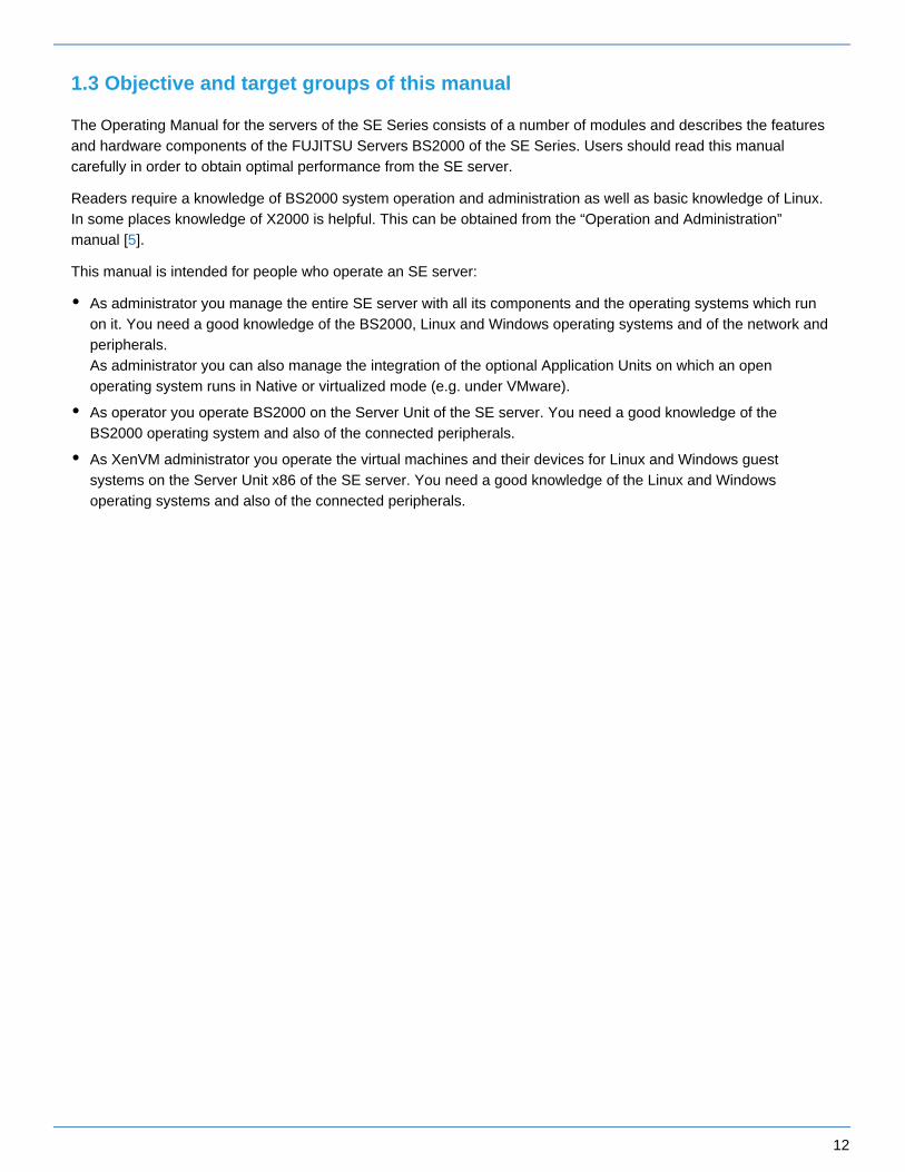
The Operating Manual for the servers of the SE Series consists of a number of modules and describes the features and hardware components of the FUJITSU Servers BS2000 of the SE Series. Users should read this manual carefully in order to obtain optimal performance from the SE server.
Readers require a knowledge of BS2000 system operation and administration as well as basic knowledge of Linux. In some places knowledge of X2000 is helpful. This can be obtained from the “Operation and Administration” manual [ ].5
This manual is intended for people who operate an SE server:
As administrator you manage the entire SE server with all its components and the operating systems which run on it. You need a good knowledge of the BS2000, Linux and Windows operating systems and of the network and peripherals. As administrator you can also manage the integration of the optional Application Units on which an open operating system runs in Native or virtualized mode (e.g. under VMware).
As operator you operate BS2000 on the Server Unit of the SE server. You need a good knowledge of the BS2000 operating system and also of the connected peripherals.
As XenVM administrator you operate the virtual machines and their devices for Linux and Windows guest systems on the Server Unit x86 of the SE server. You need a good knowledge of the Linux and Windows operating systems and also of the connected peripherals.
13
1.4 Summary of contents
This operating manual deals with the hardware-related display and operating functions of the FUJITSU BS2000 servers of the SE Series.
The chapter "Important notes" contains important information on the installation and safe operation of the SE server and the components.
The content of the following chapters describes the components of the SE server, their position in the rack, the controls, MU and NU as well as how to switch the server on and off. There is also a chapter containing the abbreviations used and their meaning.
A glossary explaining important terms used in this manual can be found in the "Administration and Operation" manual .[5]
References to publications are given in the text with shortened forms of the titles in quotes. The "Related publications" chapter lists the full title of each document that is referred to.

14
1.5 Changes to the predecessor manual
This release describes optional hardware components that are supported by the basic software M2000/X2000/HNC V6.3A or higher:
New hardware generation SE310 and SE710
Instead of MU M1/M2, with SE310 and SE710 a new variant MU M3 of the hardware base is used.
Instead of HNC M1/M2, with SE710 a new variant HNC M3 of the hardware base is used.
Instead of SU300, with SE310 a new variant SU310 of the hardware base is used.
Instead of SU700, with SE710 a new variant SU710 of the hardware base is used.

15
1.6 Notational conventions
The following are used in this manual:notational conventions
This indicates a hazardous situation which if the could result in serious personal injuryuser does not perform the procedure correctly.
This indicates a hazardous situation which could result in minor or moderate personal , if the user does not perform the procedure correctly. injury
This signal also indicates that damage to the product or other property occur if the mayuser does not perform the procedure correctly.This indicates also the tasks which are performed by Customer Support.
This indicates information that could help the user to use the product more effectively.
> The prompt symbol indicates activities which need to be performed (e.g. entries on the keyboard).
italics Texts from the SE Manager
monospace System inputs and outputs
monospace
semibold
Statements which are entered via the keyboard are displayed in this font.
<abc> Variables which are replaced by values.
[number] The titles of related publications in the text are abbreviated. The complete title of each publication which is referred to by a number is listed in the Related Publications chapter after the associated number.
Names and abbreviations
Because the names are used frequently, for the sake of simplicity and clarity the following are abbreviationsemployed:
SE server for the FUJITSU Server BS2000 SE Series (Server Units /390 and x86) with the following models:
SE300 for FUJITSU Server BS2000 SE300 (with SU300, optionally AUs)
SE500 for FUJITSU Server BS2000 SE500 (with SU500, optionally SU300 and AUs)
SE700 for FUJITSU Server BS2000 SE700 (with SU700, optionally SU300 and AUs)
WARNING!!
CAUTION!!
i

16
SU for the Server Unit irrespective of the unit typeA distinction is made between SUs depending on the unit type:
SU /390 for Server Unit /390 (type of Server Unit with one or more /390 processors)
SU x86 for Server Unit x86 (type of Server Unit with one or more x86 processors)
A distinction is made between the following SUs according to models:
SU300 for the Server Unit of the unit type SU x86 in SE300, optionally in SE500 / SE700
SU500 for the Server Unit of the unit type SU /390 in SE500
SU700 for the Server Unit of the unit type SU /390 in SE700
MU for the Management Unit. The MU permits central, user-friendly and cross-system management on the SE server.
AU for the Application Unit (on a varying hardware base) A distinction is made between the models according to the hardware base. is, for example, an Application AU47Unit based on a PRIMERGY RX4770.
HNC (High Speed Net Connect) The HNC connects the Server Unit /390 to the LAN and as the net client enables the BS2000 systems on the SU /390 to access the Net-Storage. HNC is also the name used for the HNC software.
SKP (service console processor) The MU and SE Manager contain the SKP functionality for an SU /390.
SVP (service processor)
BS2000 server as the generic term for SE server, S and SQ server. BS2000 servers are operated with the relevant BS2000 operating system.
S server for the Business Servers of the S Series (/390 architecture)
SQ server for the business servers of the SQ Series (x86 architecture)
BS2000 for the BS2000 OSD/BC operating system in compound nouns, e.g. BS2000 system.

17
2 Important notes
In this chapter the following subjects are discussed:
Notes from the manufacturer
Notes on safety
Installation and operation precautions

18
2.1 Notes from the manufacturer
The system fulfills the requirements of the EU directives 2004/108/EC "Electromagnetic Compatibility" and 2006/95/EC "Low Voltage Directive", 2009/125/EC (Ecodesign) and the directive regarding the restriction of the use of particular hazardous substances in electrical and electronic equipment 2011/65/EU. Each individual component bears the CE Marking to confirm this (CE = Communauté Européenne).
For safe operation
This manual contains important information regarding the use and handling of this product. Read this manual thoroughly. Pay special attention to the Use the product according to the instructions and section "Note on safety"information available in this manual. Keep this manual handy for further reference.The manufacturer makes every effort to prevent users and bystanders from being injured or from suffering damage to their property. Use the product according to this manual.
About this product
The FUJITSU Server BS2000 of the SE Series is designed and manufactured for use in standard applications such as computing center work, office work, and general industrial applications. This product is not intended for use in nuclear-reactor control systems, aeronautical and space systems, air traffic control systems, mass transportation control systems, medical devices for life support, missile launch control systems or other specialized uses in which extremely high levels of reliability are required, the required levels of safety cannot be guaranteed, or a failure or operational error could be life-threatening or could cause physical injury.
You may not use the product in areas with high safety requirements without ensuring the required level of safety. If you wish to use this product in an area of application with high safety requirements please consult the responsible sales representatives before use.
Trademark acknowledgments
Linux is a free multiplatform multiuser operating system.
Ethernet is a registered trademark of Xerox Corporation in the United States and in certain other countries.
All other product names mentioned herein are the trademarks or registered trademarks of their respective owners.
System and product names in this manual are not always noted with trademark (™) or registered trademark symbols (®).
These safety-critical areas of application are hereafter referred to as “Areas of application with high safety requirements”.
i

19
2.2 Notes on safety
Note regarding radio interference suppression
Important alert messages
Warning
Possible damage to the system if used incorrectlyBe sure to follow the precautions below when installing the equipment. Otherwise, the business server may be damaged.
Possible damage to the system if used incorrectlyIn the factory all the power cables are connected to the power distribution units which are integrated into the rack. Attach the connection cables of the multiple socket outlets to the in-house installation so that they are easy to access.Do not connect any additional consumer loads to the power distribution units - this could cause the nominal load capacity of the multiple socket outlet or feed cables / fuses to be exceeded! If you want to connect additional equipment, please contact Customer Support.
Possible data loss if used incorrectlyBefore shutting down power, you should ensure that the following events occur; otherwise data may be destroyed.All applications have finished processing.No user is using the components. When a unit of the SE server (MU, SU, HNC or AU) is turned off, the operating status indicator lights up orange. Check this before shutting down the main power (to UPS, power cable, and power distribution box).If necessary, back up files before shutting down.
WARNING!
This is a product which meets Class A of EN55022. In a domestic environment this product may cause radio interference in which case the user may be required to take adequate measures.
!
CAUTION!
This alert signal indicates a hazardous situation that could result in minor or moderate personal injury if the user does not perform the procedure correctly. This signal also indicates that damage to the product or other property may occur if the user does not perform the procedure correctly.
!

20
Maintenance
WARNING!
All maintenance measures which are described in this manual may only be performed by the Customer Support. Incorrect performance of these tasks may cause electric shock, injury, or fire.
Installation and reinstallation of all components, and initial settings
Removal of front, rear, or side covers
Mounting/de-mounting of optional internal devices
Plugging or unplugging of external interface cables
Maintenance and inspections (repairing, and regular diagnostics and maintenance)
!
CAUTION!
All maintenance measures for this product and the optional products of the manufacturer may only be performed by Customer Support. Users must not perform these tasks. Incorrect operation of these tasks may cause malfunction.
!
21
2.3 Installation and operation precautions
Installation precautions
Follow the instructions below to ensure safety when positioning the SE server:
The Server Unit, Management Unit, Application Units and further components are installed in one or more closed racks. Consequently the ambient operating temperature inside the rack may be higher than the room temperature. Install the business server in an environment in which the ambient temperature is always below 35 °C (95 °F).
Adjust air circulation to prevent the temperature inside the rack from exceeding the maximum ambient temperature specified for the server components.
The maximum allowable operating temperature of the server components is 35°C (95 °F).
A certain amount of air flow is required for safe operation of the server components.
The server components have ventilation openings at the front and rear. Do not cover or close the ventilation openings. Doing so may cause the server components to overheat.
Positioning the Business Server may cause the entire rack to be unstable because of uneven mechanical loading.
The racks of the SE server have no stabilizer. When an SU or heavy peripherals are pulled out of the rack, there may therefore be a risk of it tipping over.
The power supply for the server components is implemented via power distribution units mounted in the rack which themselves must be connected to the inhouse power supply using appropriate CEE connectors.
The large number of power supply components in the rack means that the configuration can generate leakage currents > 3.5 mA.
For this reason the rack may be connected to the in-house power network only via permanent links or industrial cables in accordance with IEC 60309 (formerly IEC 309) .
CAUTION!Equipment damage
Be sure to follow the precautions below when installing or operating the equipment. Otherwise, the SE server may be damaged.
!
WARNING!
The SE server is installed on the vendor’s premises. Modifications may only be carried out by Customer Support. The customer may not make any changes to the server!
The following section is therefore for information purposes only.
!
CAUTION!Equipment damage
In configurations with multiple feed cables such as the SE server, it must be noted that all cables must be disconnected to disconnect the system from the power network.
!

22
Operating precautions
WARNING!Danger of electric shock and fire
Do not damage, break or modify the cables. Cable breaks can cause electric shocks and fires.
!
CAUTION!Equipment damage
Do not cover or block ventilation openings.
Install the SE server in a location away from direct sunlight and sources of heat.
Install the Server Unit in an environment free of dust, corrosive gases, and salt air.
Install the business server in a location free of vibration and on an even surface to prevent the business server from leaning.
Do not run any cable beneath any equipment. Also, prevent cables from becoming taut. Never disconnect the power cable of the Server Unit while power is being supplied to the SE server.
Keep objects off the rack and the rack components. Never use the rack as a work area.
Do not allow condensation to form. In winter, slowly raise the ambient room temperature to prevent condensation from forming in the Server Unit.
Use the SE server only after it has warmed up sufficiently.
Operate the SE server away from noise-generating sources, such as photocopiers, air conditioners, and welding equipment.
Take preventive measures to control electrostatic buildup. Note that carpets often generate static charge which may cause the SE server to malfunction.
When moving the business server, do not pull on the front cover. Doing so may cause damage to the SE server.
!
23
3 System overview
The description is divided into the following sections:
Features
Rack of the SE server
Expanded maintenance and operational functions

24
3.1 Features
The FUJITSU Server BS2000 SE Series comprises several models whose total operating performance is determined by the number of CPUs in the Server Unit. All models have at least one CPU for BS2000 OSD/XC, the BS2000 operating system complemented by additional system-related software products.
A FUJITSU Server BS2000 of the SE Series (SE server for short) consists of the following components:
Management Unit (MU) with SE Manager An autonomous server known as the "Management Unit" (MU) is integrated into the rack for monitoring and central operation of the system. For SU /390 the MU performs SVP operation. Remote service of the SE server is performed by means of AIS Connect (over the internet). For AIS Connect the Management Unit requires an internet access over the administration LAN. The customer operates the access for remote service via the SE Manager.
Server UnitA /390-based Server Unit (SU /390) as well as an x86-based Server Unit (SU x86) enables operation of BS2000 (Native BS2000 or VM2000). In the basic configuration the SE server is equipped with one Server Unit:
SE /390 in its basic configuration with one SU /390 18 models with 1 to 16 processors are available.
SE x86 in its basic configuration with one SU x86 The SU x86 provides BS2000 performance solely on the basis of x86 technology. Several models are available with 1 to 16 XEON processor cores. In terms of processor performance, configurability and scalability of the monoprocessor performance, the SU x86 models range below the SU /390 models.
SE servers SE700, SE500 and SE300 can optionally be equipped with additional SU x86s. For example, an SE700 can be equipped with up to two SU300s, and an SE300 with up to three SU300s.SE servers SE710 and SE310 can only contain exactly one SU.
Net Unit, for SU /390 with HNC Gigabit Ethernet Switches are integrated into the rack for internal communication. In the case of SE /390 the Net Unit is by default redundant in design. In the case of SE x86, redundancy of the Net Unit is optional. In the case of SE /390 one ore more HNCs provide the LAN connections for the SU /390.
Rack console and KVM switch
Application Unit (AU) Optionally up to 32 AUs can be operated on the SE server for customer applications. An x86-based AU permits operation under Linux, Windows, VMware or other hypervisors.
Peripherals (storage)
Optional hardware components:
On SE310 ETERNUS DX100 disk storage systems resp. on SE700/SE500/SE300 up to two ETERNUS JX40 disk storage systems can optionally be integrated into the rack to back up the user data and can be connected to an SU x86 or AU. Further disk storage systems (e.g. ETERNUS DX) can optionally be connected via Fibre Channel.
On SE710/SE310 ETERNUS LT140 tape libraries resp. on SE700/SE500/SE300 ETERNUS LT40 S2 tape libraries with LTO drives can optionally be integrated into the rack to back up the user data and can be connected to an SU x86 or AU. Further tape libraries (e.g. ETERNUS CS HE and Scalar i500, i6000, 10000) can optionally be connected via Fibre Channel.

25
All components of the SE server are integrated into a joint rack (depending on the configuration, further racks are optionally possible). Information on the current hardware configuration of your SE server is displayed by the SE Manager in the menu (see the "Operation and Administration" manual [ ]).Hardware -> HW Inventory 5
Detailed information on the installation data, in particular on the dimensions and weights, is provided in the data sheet "FUJITSU Server BS2000 SE Series". See the product site for the relevant server at https://www.fujitsu.com/emeia/products/computing/servers/mainframe
:/bs2000/
> Go to and select the desired SE server model.FUJITSU Server BS2000

26
3.1.1 Rack of the SE server
SE300 / SE310
The following two figures show how the basic rack of the SE300 resp. the SE310 is equipped with the components of the basic configuration and with optional components.
Figure 3: System components SE300 and SE300B
The following differences arise with the SE310: The rack height is 42 instead of 37 height units. The SU310 has only 2 height units instead of 4 height units for the SU300.

27
Figure 4: System components SE310 (basic configuration on the left, with optional components on the right)
SE700 / SE710 and SE500
The following two figures show how the basic rack of the SE700 resp. the SE710 is equipped with the components of the basic configuration and with optional components. The equipment for the SE500 is comparable to SE700.

28
Figure 5: System components SE700 and SE700B
The following difference arises with the SE710: The rack height is 42 instead of 37 height units.

29
Figure 6: System components SE710 (basic configuration on the left, with optional components on the right)

30
3.1.2 Expanded maintenance and operational functions
The equipment maintenance feature of the SE server is designed to prevent fault events occurring. The Management Unit monitors the hardware status of the Management Unit, Server Unit(s) and Application Unit(s). Detected faults are displayed in the SE Manager and reported to the vendor's Support Center via remote service.
At every Management Unit, the SE Manager shows the hardware status of all Management Units, Server Units and Application Units of the respective SE server configuration. Accordingly, in the case of a Management Cluster the Units of the involved SE Servers are monitored.
The Event Logging of the SE Manager logs events that have occurred. SE Manager's Alarm Management allows you to notify management systems by SNMP trap or users by e-mail when certain events occur.
Detailed information on the monitoring functions is provided in the "Operation and Administration" manual [ ].5
CAUTION!
You are forbidden from repairing components of the server yourself. Maintenance and repair of the server components are performed solely by Customer Support. If a fault occurs, please always contact Customer Support.
!
31
4 Racks
The description is divided into the following sections:
Basic rack
Extension rack
Power supply

32
4.1 Basic rack
The components of the SE server are integrated into the basic rack, a 19-inch standard rack. In the case of the SE700/SE710 and SE500 the control panel is located on the front (see ). If section "Control panel (on the SE /390)"the basic rack is not longer adequate for larger configurations, extension racks can be used.
Figure 7: Basic rack (SE700 / SE500 / SE300)

33
Figure 8: Basic rack (SE710 / SE310)
34
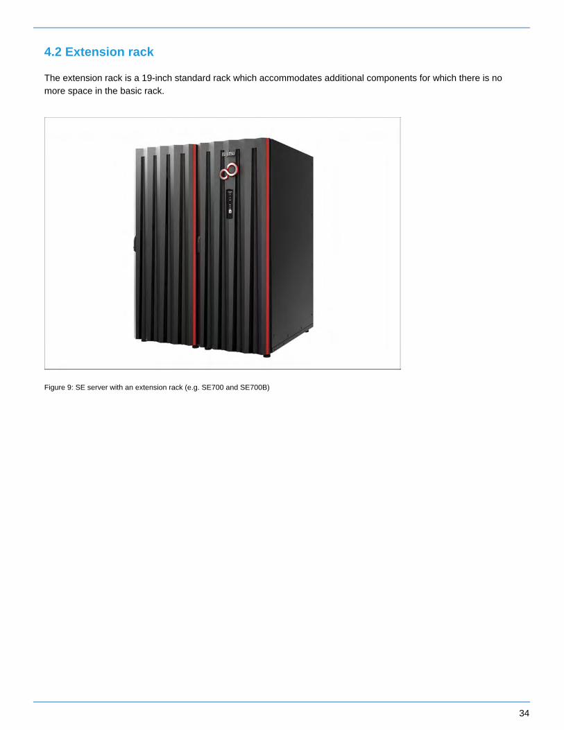
4.2 Extension rack
The extension rack is a 19-inch standard rack which accommodates additional components for which there is no more space in the basic rack.
Figure 9: SE server with an extension rack (e.g. SE700 and SE700B)

35
Figure 10: SE710 with two extension racks
In all an SE server can comprise at most four extension racks.

36
4.3 Power supply
The devices in the racks are supplied with power over power distribution units (PDUs).
SE /390
By default a basic rack contains four PDUs, each with 8 or 11 x C13 outlets.
Each PDU is connected to the in-house power grid with CEE connectors 32A resp. 16A (SE710) blue. For redundancy reasons, two phases are required. Two of the four CEE connectors are connected to each phase.
SE x86
The power distribution units to be installed in the SE300 basic rack and in the extension racks can be selected. The following three types of PDU can be installed:
PDU with 10 x C13 outlets, CEE connector 16A blue
3-phase PDU with 3 x 8 x C13 outlets, CEE connector 16A red
PDU with 8 x C13 outlets, CEE connector 32A blue
Connection of the power cables
Most of the hardware components in the SE server rack do not incorporate any switches which disconnect them from the power source. Consequently the power cables of the hardware components must be attached or detached when it is necessary to connect or disconnect the components from the power source.
Figure 11: Example of a power distribution unit as used in the rack
CAUTION!Equipment damage
All work on the power supply must be conducted by Customer Support.
Connect each power cable to a grounded service outlet located within the operator's reach.
!

37
The power cables must be connected in such a manner that the power consumption of the rack components does not exceed the maximum rated current of the circuit’s fuse and the maximum permissible current of the fuses in the power distribution unit in the rack.
Free sockets in the power distribution unit may not be used to connect other devices. The total permissible current for a power distribution unit could be exceeded if other devices were connected. If you have additional requirements, please contact Customer Support.

38
5 Controls
The description is divided into the following sections:
Rack console
Console switch
Control panel (on the SE /390)
Function of the displays
Function of the keys and switches

39
5.1 Rack console
The rack console contains the following in a compact 19'' slide-in housing (1 HU):
A fold-out 17'' TFT color LCD monitor with a control panel and screen menu
A keyboard with US/international assignment with an integrated number pad
A touchpad with a scroll bar
Left and right mouse buttons
Monitor, keyboard and touchpad are protected in the slide-in module.
The rack console serves as the local console:
Entries from the rack console are normally transferred to the Management Unit.Outputs to the rack console normally come from the Management Unit, depending on the setting of the console switch, see .section "Console switch"
After you have logged in on the local console, you can call the SE Manager via the local desktop's browser.
Safety instructions
Pull the rack console slowly toward you until the slide rails lock. If the slide rails are not locked, the rack console can move unexpectedly. Be careful not to catch your fingers when you pull or push on the slide module or when you open or close the LCD, etc.
Do not apply any strong force to the rack console when it is pulled out or when the monitor is opened and being used.
Do not press strongly on the monitor's screen, scratch it with sharp objects, or bring magnetic objects near it. Doing so can damage the monitor.
Note that the corners of the open device can be dangerous if bumped into. Always be careful when the device is open.
We recommend that you store the rack console in the rack when not in use.
Sliding the rack console out of the rack
> Loosen the finger screws (1)
> Pull the rack console while you hold the handle (2) until it locks into place.

40
Opening the rack console
> Use the handle to push the cover of the rack console up until the monitor is open at an angle of 110 degrees.
Monitor operating panel
The operating panel is at the bottom right of the monitor.
1 Power button Press this button to turn on the power to the monitor, or, if the power is already on, to turn off the power to the monitor.
2 Power LED This LED lights up green when the power to the monitor is on, and lights orange when the monitor is in energy-saving mode. The light goes off when the monitor is turned off.
3 MENU/ENTER button Press this button to open the menu, to select an item to be adjusted, and to save an adjusted setting.
4 UP button Press this button to select the right-hand item or to increase the value.

41
5 DOWN button Press this button to select the left-hand item or to increase the value.
6 AUTO/EXIT button Press this button to close the menu, to cancel the selection of an item to be adjusted, to cancel an adjusted setting, or to perform automatic adjustment.
Menu control
> Press the MENU/ENTER button (3).The main menu is opened. The menu item selected is highlighted.
> Use the UP and DOWN buttons (4 and 5) to go to the required menu item.
> Select an item with the MENU/ENTER button (3). The list entry selected is highlighted.
> Use the MENU/ENTER button (3) and the UP and DOWN buttons (4 and 5) to add the settings to the list entries selected.
> Confirm each of your settings by pressing the MENU/ENTER button (3).
> Quit the list entry, the menu item and the menu using the AUTO/EXIT button (6).
Switching the monitor on
> Press the power button (1) to turn the monitor on.
Notes on the LCD Display
While the on-screen display may shift, blink, or otherwise be disturbed just after the power is turned on or the OS starts up/shuts down, this does not indicate a machine failure, and the device may be used normally.
While 1280 × 1024 is the native full-screen resolution, the LCD display is full screen for all resolutions.For resolutions other than 1280 × 1024, characters may be blurred and the thickness of thin lines can be uneven.This is because the full-screen display is made by digital interpolation of the low-res output, not by physical magnification. This is not a machine failure, and the device may be used normally.
Although there might be some always-off dots or some always-on dots, this is accepted as it is a natural characteristic of LCDs, not as a fatal imperfection. So use this device normally.
Keyboard operations
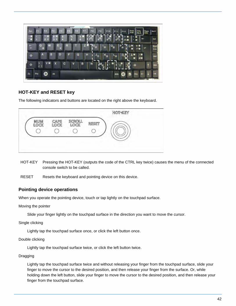
Using the Fn key on the compact layout keyboard of this device allows functions equivalent to a full keyboard.
By pressing both the Fn key and a key with underscored characters, you can use the function indicated by the characters (for example, Scr Lk, Prt Sc, and SysRq).
When the Num Lock LED is lit, the functions indicated by the enclosed characters shown on some keys are enabled.
It is possible to directly adjust the screen brightness by pressing the UP or DOWN button when the menu is not displayed.It is possible to perform automatic adjustment (position and focus) by pressing the AUTO/EXIT button.
i
42
HOT-KEY and RESET key
The following indicators and buttons are located on the right above the keyboard.
HOT-KEY Pressing the HOT-KEY (outputs the code of the CTRL key twice) causes the menu of the connected console switch to be called.
RESET Resets the keyboard and pointing device on this device.
Pointing device operations
When you operate the pointing device, touch or tap lightly on the touchpad surface.
Moving the pointer
Slide your finger lightly on the touchpad surface in the direction you want to move the cursor.
Single clicking
Lightly tap the touchpad surface once, or click the left button once.
Double clicking
Lightly tap the touchpad surface twice, or click the left button twice.
Dragging
Lightly tap the touchpad surface twice and without releasing your finger from the touchpad surface, slide your finger to move the cursor to the desired position, and then release your finger from the surface. Or, while holding down the left button, slide your finger to move the cursor to the desired position, and then release your finger from the touchpad surface.
43
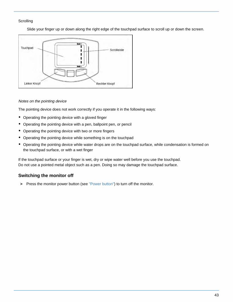
Scrolling
Slide your finger up or down along the right edge of the touchpad surface to scroll up or down the screen.
Notes on the pointing device
The pointing device does not work correctly if you operate it in the following ways:
Operating the pointing device with a gloved finger
Operating the pointing device with a pen, ballpoint pen, or pencil
Operating the pointing device with two or more fingers
Operating the pointing device while something is on the touchpad
Operating the pointing device while water drops are on the touchpad surface, while condensation is formed on the touchpad surface, or with a wet finger
If the touchpad surface or your finger is wet, dry or wipe water well before you use the touchpad.Do not use a pointed metal object such as a pen. Doing so may damage the touchpad surface.
Switching the monitor off
> Press the monitor power button (see ) to turn off the monitor."Power button"
44
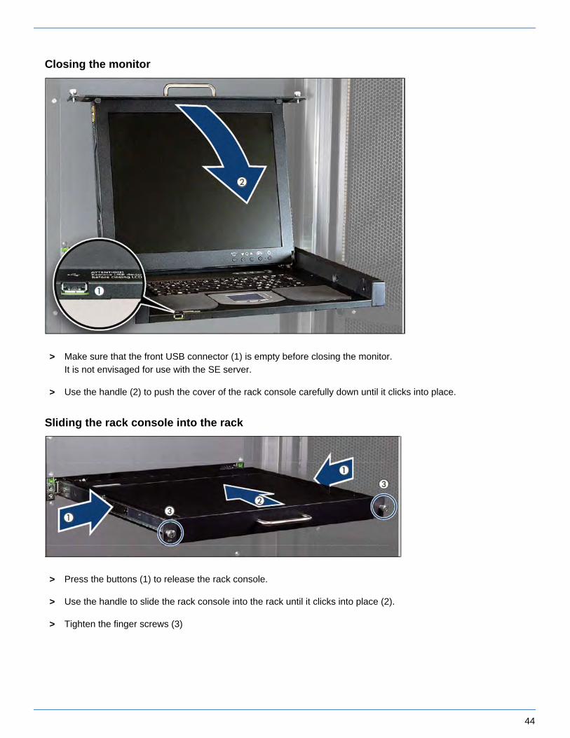
Closing the monitor
> Make sure that the front USB connector (1) is empty before closing the monitor.It is not envisaged for use with the SE server.
> Use the handle (2) to push the cover of the rack console carefully down until it clicks into place.
Sliding the rack console into the rack
> Press the buttons (1) to release the rack console.
> Use the handle to slide the rack console into the rack until it clicks into place (2).
> Tighten the finger screws (3)

45
Troubleshooting
No image is displayed on the monitor:
Symptom Cause Action
The power LED is out. The power is not turned on. Press the power button.
The monitor does not functioncorrectly after being turned on.
Notify Customer Support.
The power LED is orange. Or,when the MENU/SELECT button is pressed,the message "Signal Going to Sleep" is displayed.
The server is in standby mode.
The monitor is incorrectlyconnected to the server.
Notify Customer Support.
The power LED lights but no imageis displayed on the monitor.
The rack console was turnedon after the server was turned on.
Turn on the device at the sametime as or before you turn on the server.
The monitor is incorrectlyconnected to the server.
Notify Customer Support.
The screen flickers. The monitor is incorrectlyconnected to the server.
Notify Customer Support.
The monitor display looks strange:
Symptom Cause Action
Grid screen that flickers. The monitor is unfocused. Adjust the focus of the monitor.
Vertical stripes are visible. Monitor adjustment is notcorrect.
Adjust the clock, and thenadjust the display position.
Sometimes no images aredisplayed on the monitor.
The monitor is incorrectlyconnected to the server.
Notify Customer Support.
Letter weights are different acrossthe monitor.
Focus or clock adjustment isnot correct.
Adjust the clock, and thenadjust the display position.
Monitor cannot be adjusted:
Symptom Cause Action
Automatic adjustment using the AUTO/EXIT button doesnot work and the following message

46
is not displayed:"AUTO Processing"
Automatic adjustment was performed with anextremely dark monitor background/image.
Make the monitor image as bright as possible, and then pressthe AUTO/EXIT button to redo automatic adjustment.

47
5.2 Console switch
The monitor, keyboard and mouse port of the integrated rack console are connected to the corresponding ports on the integrated units (Management Unit, Server Unit x86, HNC, and Application Unit) and thus attached to one of them.
By default, the rack console is attached to the first Management Unit.
The console switch is usually a digital 8- or 16-port KVM switch. The KVM switch is integrated into the rack in a vertical position and therefore does not require a height unit.
In the maximum configuration, 5 KVM ports (2 x MU and 3 x SU x86) are occupied in the SE x86, and 8 KVM ports (2 x MU, 4 x HNC and 2 x SU x86) in the SE /390, additional AUs where required. If more AUs are to be integrated into the SE server, the KVM switch can be replaced with a different KVM switch with 16 or 32 ports. In this case, please contact your sales representative.
48
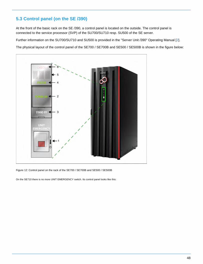
5.3 Control panel (on the SE /390)
At the front of the basic rack on the SE /390, a control panel is located on the outside. The control panel is connected to the service processor (SVP) of the SU700/SU710 resp. SU500 of the SE server.
Further information on the SU700/SU710 and SU500 is provided in the "Server Unit /390" Operating Manual [ ].2
The physical layout of the control panel of the SE700 / SE700B and SE500 / SE500B is shown in the figure below:
Figure 12: Control panel on the rack of the SE700 / SE700B and SE500 / SE500B
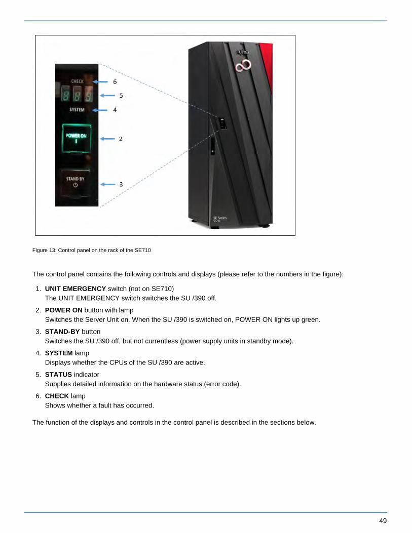
On the SE710 there is no more UNIT EMERGENCY switch. Its control panel looks like this:
49
1.
2.
3.
4.
5.
6.
Figure 13: Control panel on the rack of the SE710
The control panel contains the following controls and displays (please refer to the numbers in the figure):
UNIT EMERGENCY switch (not on SE710)The UNIT EMERGENCY switch switches the SU /390 off.
POWER ON button with lamp Switches the Server Unit on. When the SU /390 is switched on, POWER ON lights up green.
STAND-BY button Switches the SU /390 off, but not currentless (power supply units in standby mode).
SYSTEM lamp Displays whether the CPUs of the SU /390 are active.
STATUS indicator Supplies detailed information on the hardware status (error code).
CHECK lampShows whether a fault has occurred.
The function of the displays and controls in the control panel is described in the sections below.

50
5.3.1 Function of the displays
POWER ON
Lights up green after the system power controller has completed the power-up sequence without error. In the standby status the indicator flashes.
SYSTEM
Lights up green when the CPU(s) is/are in operation.
CHECK
Lights up red when the SVP has detected a hardware malfunction or a fault in the power supply of the SU /390. In the event of a fault a buzzer sounds at the same time.
STATUS indicator
Depending on the POWER ON indicator, this indicator is switched on and displays details of the hardware status with a three-character alphanumeric display. The display changes as sequences are executed. If the display finally stops at a particular value not equal to "000", this must be interpreted as the error code for a problem. In this case Customer Support should be contacted.
POWER ON STATUS indicator
Hardware status
Does not light up
Does not light up
Power failure
Does not light up
b00 through bFF
Power supply units are being initialized.
Flashing Does not light up (in maintenance mode CE0)
Standby mode
Lights up 001 through 010
Power-on sequence is active.
Lights up 100 through 399
System is being initialized.
Lights up 000 System initialization completed.
Lights up 500 through 599
System stop initiated.
Lights up 010 through 001
Power-off sequence is active.
Lights up or does not light
Begins with A
The entire /390 system (CPU box, AROMA, CHE boxes) or parts of it have been switched off because of a fault (power supply or operating temperature). Or an important function of the SVP has been stopped and a detailed error code cannot be displayed on the SVP console.

51
up (depending on the STATUS)
Lights up EEE Another error has occurred. A detailed error code is displayed on the SVP console.
Table 1: STATUS indicator

52
1.
2.
1.
2.
5.3.2 Function of the keys and switches
UNIT EMERGENCY switch (SE700 / SE500 only)
The UNIT EMERGENCY switch switches the system off as quickly as possible when an emergency or disaster occurs. The Server Unit is switched off immediately when the switch is pressed. This switch should only be used in the utmost emergency. If there is still time, the system should be switched off normally using the STAND-BY key.
Procedure in the event of an emergency power-off:
Pull out and remove the protective cover of the UNIT EMERGENCY switch.
Move the switch down (from position to position ).I 0
POWER ON key
This key initiates the sequential power-on of the power supplies of the entire /390 system (/390-CPU, AROMA, CHE boxes). They are powered on independently of an automatic power-on/off function.
IMPL (Initial Micro Program Load) is then performed. The system is ready when POWER ON lights up and the status indicator displays 000.
When POWER ON IPL is configured, the operating system is then loaded (see SVP frame LOAD PRESET1, "Server Unit /390” Operating Manual [ ]).2
Before pressing the POWER ON key, check whether the following requirements are met:
POWER ON is flashing and the status indicator displays nothing. When all displays are off and the status indicator displays nothing, the power supply of the Server Unit is switched off. In this case switch the fuses in the power distribution cabinet on to supply the Server Unit with power.
The status indicator displays no error code. If an error code is displayed, notify Customer Service of this error code.
Press the POWER ON key to begin powering up the system. The power-up sequence begins. POWER ON lights up and the status indicator displays a sequence from 001 through 399 while powering up.
CAUTION!
There is a risk of data loss. When the UNIT EMERGENCY switch is pressed, system data can no longer be written back. After it has been pressed, the UNIT EMERGENCY switch is mechanically locked. POWER ON can only be used again to switch the system on when the lock has been canceled by Customer Support.
!
CAUTION!Danger of fire and electric shock
After the UNIT EMERGENCY has been pressed, some of the circuits remain live! Only some of the circuits are switched off. Switch off the fuses in the power distribution cabinet to eliminate this danger.
!

53
The system is ready when POWER ON lights up and the status indicator displays 000. If the status indicator displays an error code, an error occurred while powering up. In this case notify Customer Service of this error code.
STAND-BY key
This key is used to switch off the power supply of the entire /390 system. It is switched off independently of an automatic power-on/off function.
Press the STAND-BY key to initiate system power-off. The power-off sequence begins. While the system is powering off, the status indicator displays a sequence from 501 through 599. When the Server Unit is switched off, POWER ON flashes and the status indicator display is empty.
Instead of using the key, the system can also be switched to standby using the SVP frame (AU4) POWER STAND-BY/IMPL. See the "Server Unit /390" Operating Manual [ ].2
CAUTION!
There is a risk of data loss. When standby mode is switched to (using the key or the SVP frame), it is not guaranteed that system data can be written back. Terminate applications which are running beforehand and shut down the operating system.
!
IMPORTANT!
In standby mode some of the circuits remain live!
!

54
6 Management Unit
An autonomous server, known as the Management Unit (MU), is integrated into the rack for central operation and administration using the SE Manager and for monitoring the units.
On the SE /390 the MU provides the SKP functionality to operate the SU /390. The MU is also the carrier system for further add-on software such as StorMan, ROBAR, openSM2, and openUTM.
On the SE /390 redundancy of the SKP functionality can be achieved by installing a second MU.
The main memory, internal disks, power supply units, and fans are redundant in design. The internal disks, power supply units, and fans can be replaced during ongoing operation.
The rack console serves as a monitor for the Management Unit and consequently as local access to the administrative and operating functions of the SE server.
The M2000 software is preinstalled ex works.
Detailed information on operating the Management Unit is provided in the "Operation and Administration" manual [5].
Detailed information on the various hardware components and interfaces of the Management Unit is provided in the data sheet "FUJITSU Server BS2000 SE Series".
See the product site for the relevant server at https://www.fujitsu.com/emeia/products/computing/servers/mainframe:/bs2000/
> Go to and select the desired SE server model.FUJITSU Server BS2000

55
6.1 Front of the MU
Figure 14: Management Unit (MU) - front of an MU M1
Figure 15: Management Unit (MU) - front of an MU M2
Indicators on the front panel of MU M1
Figure 16: MU M1 (front panel)
1 HDD fault indicator
2 Power supply fault indicator
3 Temperature fault indicator
4 CPU fault indicator (notify Customer Support)
5 Storage fault indicator (notify Customer Support)
6 Fan fault indicator (notify Customer Support)
7 ID indicator
8 CSS indicator (notify Customer Support)
9 Global error indicator (notify Customer Support)

56
10 HDD activity indicator
11 Status indicator
12 On/Off button
13 NMI button (for Customer Support only)
14 Reset button (for Customer Support only)
15 ID button
16 Open/close optical drive
17 Optical drive activity indicator
18 ID card (green)
Indicators on the front panel of MU M2
Figure 17: MU M2 (front panel)
1 Reset button (for Customer Support only)
2 NMI button (for Customer Support only)
3 ID button / ID indicator
4 CSS indicator (orange); notify Customer Support
5 Global error indicator (orange); notify Customer Support
6 HDD/SSD activity indicator
7 On/Off button / Status indicator
8 Status indicator (power cable connected); next to the On/Off switch

57
9 Optical drive activity indicator
10 Open/close optical drive
11 ID card (green); further left, above HDD module
The DVD-RW drive is used by Customer Support to install and update the M2000 software.
Use of the USB interfaces is reserved for Customer Support.
You can pull the ID card out and push it in again as far as it will go. The ID card contains various system information, e.g. product name, serial number, MAC addresses and DNS name.
Indicators on the front panel of MU M3
Figure 18: Indicators and control elements on the front panel of MU M3
Pos. Label Key / Display
Function Status
1 RESET Reset key System restart (for Customer Support only)
2 NMI NMI key For Customer Support only
3 ID ID button / ID indicator
Identifies the ID display on the front panel and at the I/O panel for an easier server identification.
blue on
4 CSS display
Notify Customer Support if on or flashing off / orange / orange flashing
5 Global error display
Notify Customer Support if on or flashing off / orange / orange flashing
6 HDD/SSD activity indicator
Data access running green flashing
7 On/Off button
Switch on server: Off / Server switched on / BMC firmware starting after connection to power grid
off / green on / green
58
flashing slowly
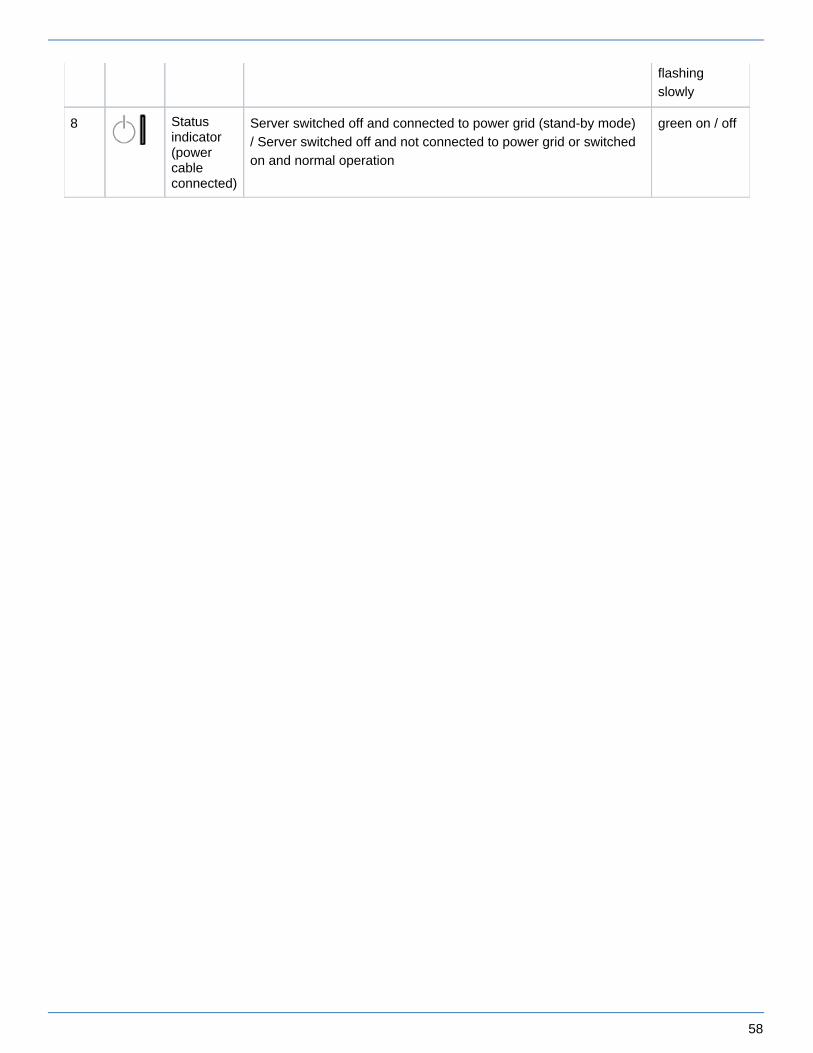
8 Status indicator(power cable connected)
Server switched off and connected to power grid (stand-by mode) / Server switched off and not connected to power grid or switched on and normal operation
green on / off
59
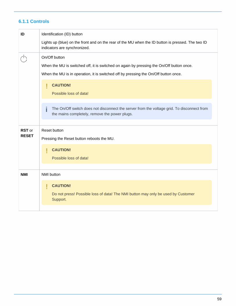
6.1.1 Controls
ID Identification (ID) button
Lights up (blue) on the front and on the rear of the MU when the ID button is pressed. The two ID indicators are synchronized.
On/Off button
When the MU is switched off, it is switched on again by pressing the On/Off button once.
When the MU is in operation, it is switched off by pressing the On/Off button once.
RST or RESET
Reset button
Pressing the Reset button reboots the MU.
NMI NMI button
CAUTION!
Possible loss of data!
!
The On/Off switch does not disconnect the server from the voltage grid. To disconnect from the mains completely, remove the power plugs.
i
CAUTION!
Possible loss of data!
!
CAUTION!
Do not press! Possible loss of data! The NMI button may only be used by Customer Support.
!

60
Indicators on the operating panel
Power-on indicator (three colors)
Lights up orange when the MU is switched off but line voltage is present. After the power cables have been connected, it takes about 60 seconds until the MU is in standby mode.
Lights up yellow during power up delay.
Lights up green when the MU is switched on.
Flashes green when the MU has been switched on and is in standby mode or in sleep mode.
Hard disk activity indicator (green)
Flashes green when an internal hard disk drive is being accessed.
CSS CSS and Global error indicators (yellow/orange)
Generally, the states of these indicators have the following meanings:
Do not light up when the MU is OK.
If the event is still acute after a power failure, the indicator is activated after the restart.
Light up when a prefailure event was detected. The indicator also lights up in standby mode.
Flash when an error was detected. The indicator also flashes in standby mode.
Irrespective of the color, when an indicator lights up or flashes this indicates an error event. Please notify Customer Support when this happens.
ID ID indicator (blue)
Lights up blue when MU has been selected by pressing the ID button. To deactivate, press the button again.
Optical drive activity indicator
Lights up green when the storage medium is accessed. See also .figure 16/17
If the MU is switched off and then immediately switched on again, it is only restarted after a power up delay. This prevents a current overload, for example.
i

61
Hard disk drive control indicators
Figure 19: Front - Detailed view: Indicators on a hard disk module
1 HDD BUSY (green)
Lights up: HDD in active phase
Does not light up: HDD inactive
2 HDD FAULT (orange) (in conjunction with a RAID controller)
Does not light up: no HDD error
Lights up: HDD Faulty or Rebuild Stopped (drive defective, needs replacing, a rebuild process was stopped or the HDD module is not correctly inserted)
Slow flashing: HDD Rebuild (the data is being restored after changing a hard disk drive)
Fast flashing: HDD Identify
Four fast flashes/pause: HDD Predicted Fault
Two fast flashes/pause: HDD Hot Spare (The corresponding drive has failed).

62
6.2 Rear of the MU
Figure 20: Management Unit (MU) - rear of an MU M1
Figure 21: Management Unit (MU) - rear of an MU M2
Figure 22: Management Unit (MU) - rear of an MU M3
Figures 20, 21 and 22 show the rear of an MU M1, MU M2 and MU M3 with PCIe slots which are not equipped.

63
ID/CSS/Global error indicator
Figure 23: ID/CSS/Global error indicator (MU M1)
Figure 24: ID/CSS/Global error indicator (MU M2)
Figure 25: ID/CSS/Global error indicator (MU M3)
1 ID/CSS/Global error indicator
ID ID indicator (blue)
Lights up blue when the MU has been selected by pressing the ID button. To deactivate, press the button again.
The ID indicator can also be activated via the ServerView Operations Manager and the iRMCS4 web interface, and the status can be reported to the ServerView Operations Manager and the iRMCS4.

64
CSS CSS and Global error indicator (yellow/orange)
Generally, the states of these indicators have the following meanings:
Do not light up when the MU is OK.
If the event is still acute after a power failure, the indicator is activated after the restart.
Light up when a prefailure event was detected. The indicator also lights up in standby mode.
Flash when an error was detected. The indicator also flashes in standby mode.
Irrespective of the color, when an indicator lights up or flashes this indicates an error event. Please notify customer support.
LAN indicators
Figure 26: LAN indicators (MU M1)
Figure 27: LAN indicators (MU M2)

65
Figure 28: LAN indicators (MU M3)
1 LAN speed Lights up green for a LAN transfer rate of 1 Gbps. for a LAN transfer rate of 100 Mbps.Lights up green
for a LAN transfer rate of 10 Mbps.Does not light up
2 LAN connection/transfer Lights up green if a LAN connection exists. if no LAN connection exists.Does not light up
when a LAN transfer is in progress.Flashes green
Indicator on hot-plug power supply unit
Figure 29: Indicator on hot-plug power supply unit
1Flashes green when the MU is switched off, but line voltage is present (standby mode).
Lights up green when the MU is switched on and functioning properly.
Flashes orange when a predictable error has been detected, but the power supply unit is still running. 1)
Flashes orange in the case of OCP/OVP or when the power supply unit's fan has failed.

66
1) The following events are detected as predictable errors:
The temperature is very high.
The power consumption is very high.
The strength of current is very high.
The fan speed is very low.
In each of these cases please notify Customer Support.
Assignment of the PCIe slots
The assignment of the PCIe slots differs between MU M1, MU M2 and MU M3.
PCIe slot assignment on an MU M1
Figure 30: Principle of PCIe slot assignment at the rear of the device (MU M1)
The figure shows the PCIe slots of the MU M1 on an SE700. On the various model series of the SE server, the PCIe slots of an MU M1 are assigned as follows:
PCIe slot SE700 SE500 SE300
S1 not assigned not assigned not assigned
S2 USB card USB card not assigned
S3 FibreChannel card FibreChannel card not assigned
Table 2: PCIe slot assignment on an MU M1
The MU M1 can be equipped with a second FibreChannel card in the free PCIe slot S1. Accordingly, two more ports are available for the ROBAR connection and cluster functionality.

67
PCIe slot assignment on the MU M2
Figure 31: Principle of PCIe slot assignment at the rear of the device (MU M2)
The figure shows the PCIe slots of the MU M2 on an SE700B. On the various model series of the SE server, the PCIe slots of an MU M2 are assigned as follows:
PCIe slot SE700B SE500B SE300B
S2 not assigned not assigned not assigned
S3 FibreChannel card FibreChannel card not assigned
S4 FibreChannel card FibreChannel card not assigned
Table 3: PCIe slot assignment on an MU M2
The MU M2 can be equipped with another FibreChannel card in the free PCIe slot S2. Accordingly, two more ports are available for the ROBAR connection and cluster functionality.
PCIe slot assignment on the MU M3
Figure 32: Principle of PCIe slot assignment at the rear of the device (MU M3)
The figure shows the PCIe slots of the MU M3 on an SE710. On the various model series of the SE server, the PCIe slots of an MU M3 are assigned as follows:
PCIe slot SE710 SE310
S2 FibreChannel card optional FibreChannel card ( CRD)
S3 optional FibreChannel card ( CRD) optional FibreChannel card ( CRD)
S4 not assigned not assigned
Table 4: PCIe slot assignment on an MU M3
The MU M3 can be equipped with another FibreChannel card in the free PCIe slot S4. Accordingly, two more ports are available for the ROBAR connection and cluster functionality.
68
7 Net Unit
The Net Unit implements the connection of the units to the networks of the SE server and to private customer networks. The Net Unit can be designed with redundancy in the interest of protection against failure.
The Net Unit contains the following components:
Switches A redundant Net Unit has redundant switches (by default in the case of SE /390).
Optional port extension A redundant Net Unit can (on SE 300) be complemented by a redundant port extension to increase the number of redundant LAN ports.
HNC in SE /390 The HNC connects the Server Unit /390 with the LAN. Up to 4 HNCs are possible.
Extensions of the Net Unit support up to 10 Gbps.

69
7.1 Switches
One switch is used in the basic configuration of the SE server SE300. By default the SE servers SE700 and SE500 have two redundant switches.
Brocade ICX 6450 models are employed.
ICX 6450-24 with
24 copper ports (10/100/1000 Mbps)
4 optical ports (SFP+; 1 oder 10 Gbps uplink ports, stacking-capable)
ICX 6450-48 with
48 copper ports (10/100/1000 Mbps)
4 optical ports (SFP+; 1 oder 10 Gbps uplink ports, stacking-capable)
Brocade switches ICX 7450-48 are used from the HW generation SE310 and SE710 onwards. These are designed redundantly as usual with SE /390, with SE x86 there is a redundancy extension (2nd switch) in addition to one switch in the basic configuration. A port extension of a redundantly designed Net Unit is no longer planned.
Currently maximum transfer speeds of up to 10 Gbps are supported.i

70
7.1.1 Front
Figure 33: Net Unit (ICX 6450-24) - front
Figure 34: Net Unit (ICX 6450-48) - front
Figure 35: Net Unit (ICX 7450-48) - front
1 System LEDs
2 Media/Stacking module LEDs
3 Stack unit ID display
4 Management port (RJ-45)
5 USB port (for flash drive)
6 Mini-USB console port
7 Reset button
8 10/100/1000Base-T RJ-45 ports 1/1/1 - 1/1/48
9 SFP+ ports 1/2/1 - 1/2/4
71
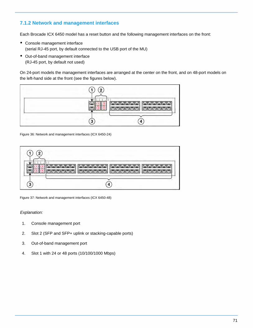
7.1.2 Network and management interfaces
Each Brocade ICX 6450 model has a reset button and the following management interfaces on the front:
Console management interface (serial RJ-45 port, by default connected to the USB port of the MU)
Out-of-band management interface (RJ-45 port, by default not used)
On 24-port models the management interfaces are arranged at the center on the front, and on 48-port models on the left-hand side at the front (see the figures below).
Figure 36: Network and management interfaces (ICX 6450-24)
Figure 37: Network and management interfaces (ICX 6450-48)
Explanation:
1. Console management port
2. Slot 2 (SFP and SFP+ uplink or stacking-capable ports)
3. Out-of-band management port
4. Slot 1 with 24 or 48 ports (10/100/1000 Mbps)
72
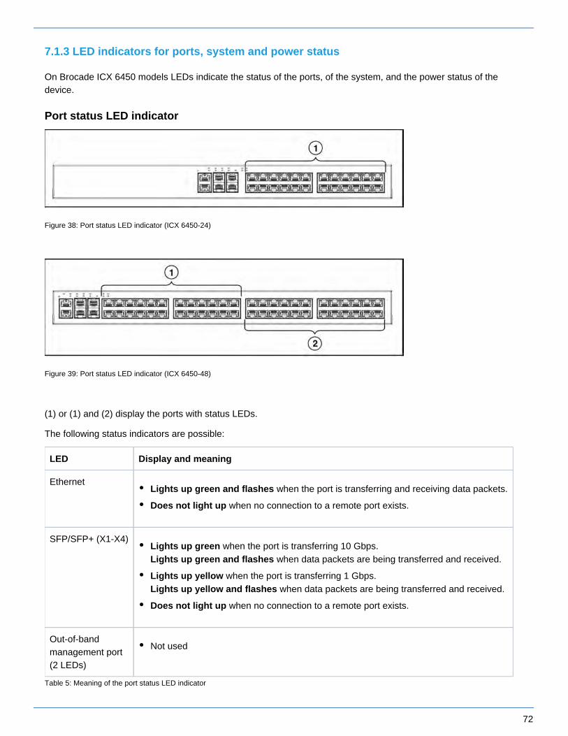
7.1.3 LED indicators for ports, system and power status
On Brocade ICX 6450 models LEDs indicate the status of the ports, of the system, and the power status of the device.
Port status LED indicator
Figure 38: Port status LED indicator (ICX 6450-24)
Figure 39: Port status LED indicator (ICX 6450-48)
(1) or (1) and (2) display the ports with status LEDs.
The following status indicators are possible:
LED Display and meaning
EthernetLights up green and flashes when the port is transferring and receiving data packets.
Does not light up when no connection to a remote port exists.
SFP/SFP+ (X1-X4)Lights up green when the port is transferring 10 Gbps.
when data packets are being transferred and received.Lights up green and flashes
Lights up yellow when the port is transferring 1 Gbps. when data packets are being transferred and received.Lights up yellow and flashes
Does not light up when no connection to a remote port exists.
Out-of-band management port (2 LEDs)
Not used
Table 5: Meaning of the port status LED indicator
73
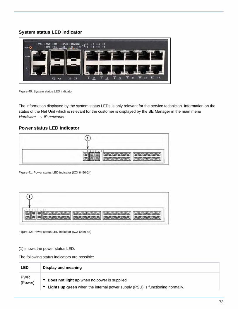
System status LED indicator
Figure 40: System status LED indicator
The information displayed by the system status LEDs is only relevant for the service technician. Information on the status of the Net Unit which is relevant for the customer is displayed by the SE Manager in the main menu
.Hardware -> IP networks
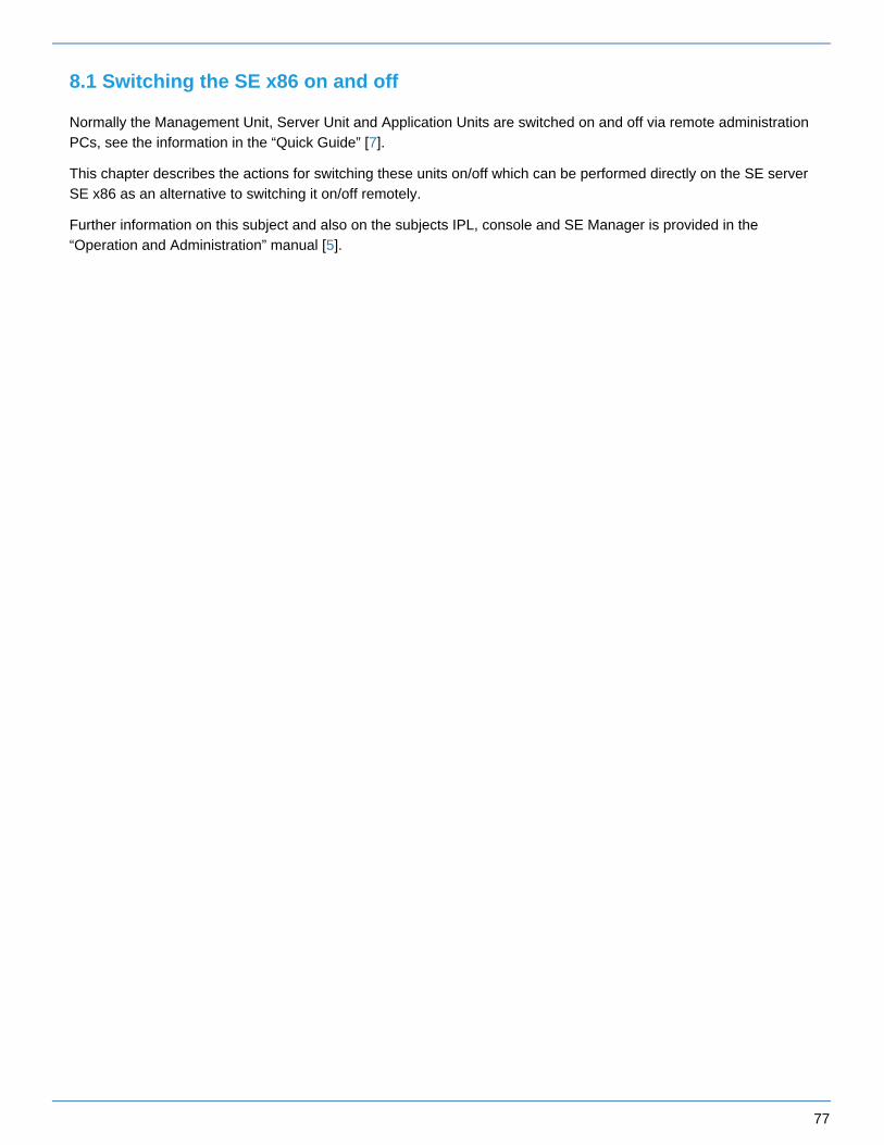
Power status LED indicator
Figure 41: Power status LED indicator (ICX 6450-24)
Figure 42: Power status LED indicator (ICX 6450-48)
(1) shows the power status LED.
The following status indicators are possible:
LED Display and meaning
PWR (Power)
Does not light up when no power is supplied.
Lights up green when the internal power supply (PSU) is functioning normally.

74
Lights up yellow when the internal power supply has failed and power is being supplied from an external power supply (EPS).
Table 6: Meaning of the power status LED indicator

75
7.2 Extension of the Net Unit
Redundant Net Unit
A redundant Net Unit has two redundant switches. The SE servers SE /390 have one redundant Net Unit in the basic configuration. The redundant Net Unit is optional for the SE x86.
On a redundant Net Unit the ports are monitored, and when an active uplink port fails, the remaining port is switched to. When the LAN segment concerned fails, the downtime is consequently reduced to the switchover time.
Port extension
On the SE servers SE700 and SE500 (not on SE710) the redundant Net Unit can be enhanced by a redundant port extension, i.e. with two switches, meaning that in the maximum configuration 96 redundant LAN ports are available.
On the SE servers SE300 (not on SE310) the port extension is possible if the Net Unit is redundant in design.
Please inquire about the current possibilities of a port extension at the Fujitsu Technology Solutions Sales department.
HNC (High-speed Net Connect) on the SE /390
The High-speed Net Connect (HNC for short) connects the Server Unit /390 with the LAN. Furthermore, as net client the HNC permits access to the Net-Storage. The SE servers SE /390 therefore incorporate an HNC in their basic configuration.
Redundancy of the HNC is an optional feature. Up to four HNCs can be integrated.
Further information on the HNC is provided in the "Server Unit /390" Operating Manual [ ].2

76
8 Switching the server on and off
The description is divided into the following sections:
Switching the SE x86 on and off
Switching off in an emergency
Switching the SE server on
Switching the SE server off
Switching the SE /390 on and off
Switching off in an emergency
Switching the SE server on
Switching the SE server off
77
8.1 Switching the SE x86 on and off
Normally the Management Unit, Server Unit and Application Units are switched on and off via remote administration PCs, see the information in the “Quick Guide” [ ].7
This chapter describes the actions for switching these units on/off which can be performed directly on the SE server SE x86 as an alternative to switching it on/off remotely.
Further information on this subject and also on the subjects IPL, console and SE Manager is provided in the “Operation and Administration” manual [ ].5

78
8.1.1 Switching off in an emergency
The SE servers SE x86 comply with the relevant safety regulations for IT equipment, including electrical office equipment.
In an emergency all the hardware components must immediately be disconnected by cutting off the power distribution units from the power source (e.g. when the housing or power cable is damaged or liquid or foreign material gets into the equipment).
If despite the emergency there is still time enough, you can also switch off Server Unit(s), Application Unit(s) and Management Unit manually via the operating panel at the front of the unit (for the MU see , and for figure 16/17/18the SU and AU see the "Server Unit x86" [ ] and "Additive Components" Operating Manuals [ ]). Optional hardware 3 4components have their own On/Off switches or are switched on/off automatically together with the Server Unit (e.g. ETERNUS JX40, see "Additive Components" [ ]).4
CAUTION!
Operation of the SE server SE x86 is then terminated ungracefully and abruptly.Notify Customer Support.
!
CAUTION!
These do not disconnect the hardware components completely from the power source. To cut the entire system off from the power source, you must must disconnect the power distribution units from the power source.Notify Customer Support.
!

79
8.1.2 Switching the SE server on
The following hardware components must be switched on in this order:
1. Switch on the optional hardware components
> Switch on the ETERNUS LT140 resp. ETERNUS LT40 S2 tape library as well as the ETERNUS DX100 S4 disk storage system using the On/Off switch at the front (see the "Additive Components" Operating Manual [4]).
> Switch on any other connected hardware components.
2. Switch on the MU
The power-on indicator (item 11 resp. 8 in ) lights up orange (POWER STAND-BY).figure 16/17/18
> Switch on the rack console by pulling out and folding out the monitor, see ."Rack console"
> Press the On/Off switch on the MU (item 12 resp. 9 in ).figure 16/17/18
The power-on indicator lights up green. The MU switches itself on, conducts a system test and starts the M2000 software. This takes a little time. Finally, on the rack console you see the login window for the Linux desktop of the local console.
> Call the SE Manager, e.g. after logging in on the local console via the browser of the Linux desktop (in the “Computer” menu in the task bar) or via an administration PC (default), see the “Operation and Administration” manual [ ].5
You can also switch on the MU remotely via the iRMC of the MU, see the “Operation and Administration” manual [].5
3. Switch on the Server Unit
Before the Server Unit is switched on, the status indicator lights up orange.
> Switch on the Server Unit by pressing the On/Off switch.
The power-on indicator lights up green. The Server Unit switches on, conducts a system test and starts X2000.
If automatic IPL is configured for BS2000, the BS2000 system (Native or as a VM2000 monitor system) is also started with the configured settings.
If automatic startup is configured for XenVMs, these systems are also started.
Further optional Server Units are switched on in the same way.
The ETERNUS JX40 S2 disk storage system is switched on automatically on a Server Unit when the Server Unit is switched on.
i
The controls and indicators of the Server Unit are described in the "Server Unit x86" Operating Manual [ ].3i

80
4. Switch on the optional Application Units
Before an Application Unit is switched on, the status indicator lights up orange (POWER STAND-BY).
> Switch on the Application Unit by pressing the On/Off switch.
The power-on indicator lights up green. The Application Unit switches on, conducts a system test and starts the operating system.
Further optional Application Units are switched on in the same way.
The controls, indicators and further on/off options for the AU are described in the "Additive Components" Operating Manual [ ].4
i

81
8.1.3 Switching the SE server off
The following hardware components must be switched off in the specified order.
1. Switch off the optional Application Units
Before an Application Unit is switched off, the power-on indicator lights up green.
> Terminate the customer applications and the operating system properly.
The Application Unit is switched off automatically and enters standby mode.The status indicator lights up orange. Check this before continuing.
Alternatively, as the administrator or AU administrator you can switch the Application Unit off using the SE Manager (menu , tab, symbol), see the “Operation and Administration” Hardware -> Units Units Power offmanual [ ].5
Further Application Units are switched off in the same way.
2. Switch off the Server Unit
> As the administrator, BS2000 administrator or a privileged operator, switch off the Server Unit using the SE Manager (menu , tab, symbol), see the “Operation and Administration” Hardware -> Units Units Power offmanual [ ].5
When the Server Unit is switched off, the BS2000 system is shut down properly taking into account the remaining runtime specified.
Before the Server Unit is switched off, the power-on indicator lights up green, and after it has been switched off, it lights up orange. Check this before continuing.
Further Server Units are switched off in the same way.
CAUTION!
This does not disconnect the hardware components completely from the power source (POWER STAND-BY). To cut the entire system off from the power source, you must must disconnect the power distribution units from the power source.Notify Customer Support.
!
If the operating system does not automatically switch off the Application Unit, hold the On/Off switch down for at least four seconds.
i
The controls, indicators and further on/off options for the AU are described in the "Additive Components" Operating Manual [ ].4
i
The controls and indicators of the Server Unit are described in the "Server Unit x86" Operating Manual [ ].3i

82
3. Switch off the MU
> Switch off the MU using the SE Manager (menu , tab, symbol), see the Hardware -> Units Units Power off“Operation and Administration” manual [ ].5
Before the MU is switched off, the power-on indicator lights up green, and after it has been switched off, it lights up orange (item 11 resp. 8 in ). Check this before continuing.figure 16/17/18
4. Switch off the optional hardware components
> Switch off the ETERNUS LT140 resp. ETERNUS LT40 S2 tape library as well as the ETERNUS DX100 S4 disk storage system using the On/Off switch on the front (see the "Additive Components" Operating Manual [4]).
> Switch off any other connected hardware components.
The ETERNUS JX40 S2 disk storage system connected to a Server Unit is switched off automatically when the Server Unit is switched off.
i

83
8.2 Switching the SE /390 on and off
Normally the Management Unit, Server Unit and Application Units are switched on and off via remote administration PCs, see the information in the “Quick Guide” [ ].7
This chapter describes the actions for switching these units on/off which can be performed directly on the SE server SE /390 as an alternative to switching it on/off remotely.
Further information on this subject and also on the subjects IPL, console and SE Manager is provided in the “Operation and Administration” manual [ ].5

84
8.2.1 Switching off in an emergency
The SE servers SE /390 comply with the relevant safety regulations for IT equipment, including electrical office equipment.
In an emergency the devices must immediately be switched off (e.g. when the housing or power cable is damaged or liquid or foreign material gets into the equipment). This can be done by pressing the POWER STAND-BY button on the server's control panel or - on SE700 and SE500 only - by pressing the UNIT EMERGENCY switch. Pressing the UNIT EMERGENCY switch causes an abbreviated power-off routine to be started. The UNIT EMERGENCY switch is - on SE700 and SE500 only - at the bottom of the control panel (see ).figure 43
Pressing the POWER STAND-BY button or UNIT EMERGENCY switch does not disconnect the system completely from the power source (POWER STAND-BY). To cut the entire system off from the power source, the fuses from the customer's in-house installation must be switched off/removed.
Please then notify Customer Support.
Figure 43: UNIT EMERGENCY switch on the SE700 or SE500

85
8.2.2 Switching the SE server on
The figure below shows the hardware involved in switching the Server Unit /390 on/off.
Figure 44: Hardware involved in switching the Server Unit /390 on/off
Detailed information on switching the hardware on/off using the SE Manager is provided in the "Operation and Administration" manual [ ].5
The following hardware components must be switched on in the specified order.
1. Switch on the optional hardware components
> Switch on the ETERNUS LT140 resp. ETERNUS LT40 S2 tape library using the On/Off switch at the front (see the "Additive Components" Operating Manual [ ]).4
> Switch on any other connected hardware components.
2. Switch on the MU
The power-on indicator (item 11 in resp. item 8 in ) lights up orange (POWER STAND-BY).figure 16 figure 17/18
> Switch on the rack console by pulling out and folding out the monitor, see ."Rack console"
> Press the On/Off switch on the MU (item 12 in resp. item 7 in ).figure 16 figure 17/18
The power-on indicator lights up green. The MU switches itself on, conducts a system test and starts the M2000 software. This takes a little time. Finally, on the rack console you see the login window for the Linux desktop of the local console.

86
> Call the SE Manager, e.g. after logging in on the local console via the browser of the Linux desktop (in the “Computer” menu in the task bar) or via an administration PC (default), see the “Operation and Administration” manual [ ].5
Redundant MUs are switched on in the same way.
You can also switch on the MU remotely via the iRMC of the MU, see the “Operation and Administration” manual [ ].5
3. Switch on the Server Unit SU /390
> As the administrator, BS2000 administrator or a privileged operator, switch on the Server Unit using the SE Manager (menu , tab, symbol), see the “Operation and Administration” Hardware -> Units Units Switch onmanual [ ].5
Alternatively you can switch the Server Unit on by pressing the POWER ON button on the server's control panel (see ). The system is ready when the status indicator on the server's control panel "Control panel (on the SE /390)"displays no further error codes.
Then you can call an SVP console window in the SE Manager and start the BS2000 system using PROGRAM LOAD FRAME: DETAIL-1. When a POWER ON IPL is configured, the BS2000 system is loaded automatically (using AUXILIARY FRAME: LOAD PRESET1). Alternatively the IPL can also be initiated in the SE Manager (see the menu [ Systems -> <se server> (SE<model>)
] , “Operation and Administration” manual [ ]).-> <unit> (SU</390>) -> BS2000 operation mode 5
4. Switch on the optional Server Units x86 (SE700/SE500 only)
Before the Server Unit is switched on, the status indicator lights up orange.
> Switch on the Server Unit by pressing the On/Off switch.
The power-on indicator lights up green. The Server Unit switches on, conducts a system test and starts X2000.
If automatic IPL is configured for BS2000, the BS2000 system (Native or as a VM2000 monitor system) is also started with the configured settings.
If automatic startup is configured for XenVMs, these systems are also started.
Further Server Units x86 are switched on in the same way.
The control panel and SVP frames of the Server Unit are described in the "Server Unit /390" Operating Manual [ ].2
i
The controls and indicators of the Server Unit are described in the "Server Unit x86" Operating Manual [ ].3i

87
5. Switch on the optional Application Units
Before an Application Unit is switched on, the status indicator lights up orange (POWER STAND-BY).
> As the administrator or AU administrator, switch on the Application Unit using the SE Manager (menu , tab, symbol), see the “Operation and Administration” manual [ ].Hardware -> Units Units Switch on 5
Alternatively, switch on the Application Unit by pressing the On/Off switch.
The power-on indicator lights up green. The Application Unit switches on, conducts a system test and starts the operating system.
Further Application Units are switched on in the same way.
The controls, indicators and further on/off options for the AU are described in the "Additive Components" Operating Manual [ ].4
i

88
8.2.3 Switching the SE server off
Figure 44 shows the hardware involved in switching the Server Unit /390 on/off.
The following hardware components must be switched off in the specified order.
1. Switch off the optional Application Units
Before the Application Unit is switched off, the power-on indicator lights up green.
> Terminate the customer applications and the operating system properly.
The Application Unit is switched off automatically and enters standby mode. The status indicator lights up orange. Check this before continuing.
Alternatively, as the administrator or AU administrator you can switch the Application Unit off using the SE Manager (menu , tab, symbol), see the “Operation and Administration” Hardware -> Units Units Switch offmanual [ ].5
Further Application Units are switched off in the same way.
2. Switch off the Server Unit SU /390
> As the administrator, BS2000 administrator or a privileged operator, switch off the Server Unit using the SE Manager (menu , tab, symbol), see the “Operation and Administration” Hardware -> Units Units Switch offmanual [ ].5
When the Server Unit is switched off, the BS2000 system is shut down properly taking into account the remaining runtime specified.
Before the Server Unit is switched off, the power-on indicator lights up green, and after it has been switched off, it lights up orange. Check this before continuing.
Alternatively you can switch the Server Unit off by pressing the STAND-BY button on the server's control panel (see ) or via the SVP console (menu item POWER STAND-BY in AUXILIARY FRAME: "Control panel (on the SE /390)"
POWER STAND-BY/IMPL). The BS2000 system should already have been shut down.
CAUTION!
This does not disconnect the hardware components completely from the power source (POWER STAND-BY). To cut the entire system off from the power source, you must must disconnect the power distribution units from the power source.Notify Customer Support.
!
If the operating system does not automatically switch off the Application Unit, hold the On/Off switch down for at least four seconds.
i
The controls, indicators and further on/off options for the AU are described in the "Additive Components" Operating Manual [ ].4
i

89
3. Switch off the optional Server Units x86 (SE700/SE500 only)
> As the administrator, BS2000 administrator or a privileged operator, switch off the Server Unit using the SE Manager (menu , tab, symbol), see the “Operation and Administration” Hardware -> Units Units Switch offmanual [ ].5
When the Server Unit is switched off, the BS2000 system is shut down properly taking into account the remaining runtime specified.
Before the Server Unit is switched off, the power-on indicator lights up green, and after it has been switched off, it lights up orange. Check this before continuing.
Further Server Units x86 are switched off in the same way.
4. Switch off the MU
> Switch off the MU using the SE Manager (menu , tab, symbol), see the Hardware -> Units Units Switch off“Operation and Administration” manual [ ]5
Before the MU is switched off, the power-on indicator lights up green, and after it has been switched off, it lights up orange (item 11 resp. 8 in ). Check this before continuing.figure 16/17/18
Redundant MUs are switched off in the same way.
5. Switch off the optional hardware components
> Switch off the ETERNUS LT140 resp. ETERNUS LT40 S2 tape library using the On/Off switch on the front (see the "Additive Components" Operating Manual [ ]).4
> Switch off any other connected hardware components.
The control panel and SVP frames of the Server Unit are described in the "Server Unit /390" Operating Manual [ ].2
i
The controls and indicators of the Server Unit are described in the "Server Unit x86" Operating Manual [ ].3i

90
9 Environmental protection and service
The FUJITSU servers have a long life expectancy, not only because of the excellent expansion options they offer, but also because of the quality of the products.
As technology continues to develop, however, ever greater volumes of data will need to be processed. More and more demands are being placed on storage capacity, speed and computer system design. So when you eventually want to replace your server with a newer model and dispose of the old device, we can also offer you support in this area.
Recycling old computer equipment is already a tradition at FUJITSU: We have been redeeming and reusing old computer systems for many years now. Even at the design stage, particular emphasis is placed on the reusability of components and materials.
Your server is manufactured to the greatest possible extent from environmentally friendly materials that can be fully recycled.
Read on through the next sections for a brief look at some of the measures we have introduced in an effort to protect the environment as well as our tips and suggestions for environmentally friendly handling of your system.
Environmentally friendly product design and development
This product has been designed in accordance with the guideline “environmentally friendly product design and development” of FUJITSU.
This means that the designers have taken into account critical factors such as durability, selection of materials and coding, emissions, packaging, the ease with which the product can be dismantled and the extent to which it can be recycled.
This saves resources and thus reduces the harm done to the environment.
Note on saving energy
If your device does not have to remain switched on permanently, only switch it on when you are ready to use it and then switch it off again during long breaks and when you finish your work.
Note on dealing with consumables
Please dispose of printer consumables and batteries in accordance with local government regulations.
Note on labeling plastic housing parts
Please avoid sticking your own labels on plastic housing parts wherever possible, since this makes it difficult to recycle them.
Take-back, recycling and disposal
Servers which are no longer required should first be used for other purposes before disposal or recycling is considered.
FUJITSU is a pioneer in matters of environmentally friendly computers and has been certified as providing environmental management in accordance with DIN EN ISO 14001. This also includes taking back your server and remarketing it or recycling it in an environmentally friendly manner.
To return your used server to FUJITSU, please contact

91
your sales representative or
a branch of FUJITSU.
An offer will be submitted to you here or your server will be recycled free of charge at our remarketing and recycling center.
Service
If you have any complaints in relation to missing parts or incomplete delivery, please contact the FUJITSU complaints department:
Email: [email protected]
Tel.: +49 (0) 3634 / 330 - 1758
Fax: +49 (0) 3634 / 330 - 1814
If you have questions on operation or if problems occur, please contact your local FUJITSU Customer Support, in Germany under:
Tel.: +49 (0) 89 3564 80 000
You can find all service numbers on the FUJITSU support pages:
http://support.ts.fujitsu.com/IndexContact.asp?OpenTab=servicedesk

92
10 Abbreviations
APCSAROMA-PAUCDDVDDVD-RWECCEDCESDFCHBAHDDHNCHUIDiRMCISDNIPITLANLCDLEDLTONMIMUOCPPCIRAIDRMURHSANSASSCSISUSU /390SU x86USBUPS
Automatic Power Control SystemAutomatic and Remote Operation ManagerApplication UnitCompact DiskDigital Versatile DiskDigital Versatile Disk - Read and WriteError Correcting CodeError Detection CodeElectrostatically Sensitive DeviceFibre ChannelHost Bus AdapterHard Disk DriveHigh-speed Net ConnectHeight UnitIDentifierIntegrated Remote Management ControllerIntegrated Services Digital NetworkInternet ProtocolInformation TechnologyLocal Area NetworkLiquid Crystal DisplayLight Emitting DiodeLinear Tape OpenNon Maskable InterruptManagement UnitOperator Control PanelPeripheral Component InterconnectRedundant Array of DisksRemote Management UnitRelative HumidityStorage Area NetworkSerial Attach SCSISmall Computer System InterfaceServer UnitServer Unit /390Server Unit x86Universal Serial BusUninterruptible Power Supply
93
11 Related publications
You can find the following BS2000 manuals on the manual server with the BS2000 documentation at .http://bs2manuals.ts.fujitsu.com
Other manuals, for example descriptions of the FUJITSU PRIMERGY and PRIMEQUEST servers, can be found on the general FUJITSU manual server at .http://manuals.ts.fujitsu.com
[1] FUJITSU Server BS2000 SE Series Basic Operating Manual
[2] FUJITSU Server BS2000 SE Series Server Unit /390Operating Manual
[3] FUJITSU Server BS2000 SE Series Server Unit x86Operating Manual
[4] FUJITSU Server BS2000 SE Series Additive ComponentsOperating Manual
[5] FUJITSU Server BS2000 SE Series Operation and AdministrationUser Guide
[6] FUJITSU Server BS2000 SE Series Security ManualUser Guide
[7] FUJITSU Server BS2000 SE Series Quick GuideUser Guide