se efi installation manual
DESCRIPTION
Installation of EFI systemTRANSCRIPT
Small engine EFI conversion kits - installation manual-v2_5.3
Copyright Ecotrons LLC 1
SE-EFI
Small Engine Electronic Fuel Injection-- Conversion Kit
Installation Manual
ECOTRONS
V2.5.3
http://www.ecotrons.com/
Small engine EFI conversion kits - installation manual-v2_5.3
Copyright Ecotrons LLC 2
COPY RIGHTS ECOTRONS LLC
ALL RIGHTS RESERVED
Note: many EFI parts in this manual are installed on aGY6 scooter engine as an example, and they can alsobe used as guidelines or illustration for all other smallengines. Some common sense shall be used toconvert a different engine. If you are not sure aboutany specific details, please contact [email protected].
.
Small engine EFI conversion kits - installation manual-v2_5.3
Copyright Ecotrons LLC 3
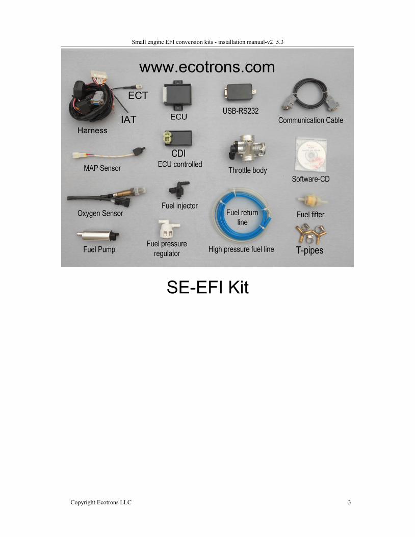
SE-EFI Kit
Small engine EFI conversion kits - installation manual-v2_5.3
Copyright Ecotrons LLC 4
IntroductionSE-EFI is an Electronic Fuel Injection conversion kit for small engines. It is abolt-on EFI kit to a lot of small engines used on variant applications: motorcycles,scooters, ATVs, Go-Carts, boats, snowmobiles, etc. The displacements of theengines can be in the range of 35cc up to 1200cc. This kit replaces the OEM'scarbureted fuel system completely, and it requires the minimum modifications ofthe engine. It could be a plug-and-play EFI kit for some popular small engines likeGY6 engines, or monkey bike engines in the range of 50cc, 125cc, 150cc; 180cc,etc. For many other engines, you may need to do some mechanical adaptations,like a throttle body adapter, etc. And also you need to do some fine tuning. Youwill get a pre-loaded software with the kit that will most likely start and run yourengine after you install it. The ECU is fully programmable, and tuning is madeeasy for those who are interested, and the tuning software is free, downloadable.
This EFI kit has below features: Electronic fuel injection (EFI) Quick engine start even at cold temperatures More power and torque than the carbureted version High fuel efficiency and low carbon emissions Decel-fuel-cut-off OBD - on board diagnosis Performance tuning for advanced users.
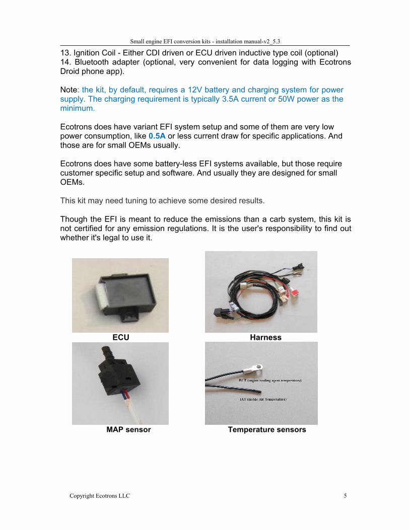
Parts:1. ECU2. Harness (including the connectors)3. Throttle Body and Intake manifold Assembly
Throttle body (including TPS sensor) Fuel injector (mounted on the throttle body)
4. Fuel pump assembly Fuel pump (outside of the tank) Fuel pressure regulator Fuel filter High pressure fuel line Fuel hoses, T-Pipes ,Clamps
5. MAP sensor6. Engine temperature sensor7. Intake air temperature sensor8. Oxygen sensor and bungs9. Serial communication cable (to a computer)10. USB adaptor - included11. CD for tuning software (downloadable from our website)12. CDI - ECU controlled (optional, you can use your own CDI).
Small engine EFI conversion kits - installation manual-v2_5.3
Copyright Ecotrons LLC 5
13. Ignition Coil - Either CDI driven or ECU driven inductive type coil (optional)14. Bluetooth adapter (optional, very convenient for data logging with EcotronsDroid phone app).
Note: the kit, by default, requires a 12V battery and charging system for powersupply. The charging requirement is typically 3.5A current or 50W power as theminimum.
Ecotrons does have variant EFI system setup and some of them are very lowpower consumption, like 0.5A or less current draw for specific applications. Andthose are for small OEMs usually.
Ecotrons does have some battery-less EFI systems available, but those requirecustomer specific setup and software. And usually they are designed for smallOEMs.
This kit may need tuning to achieve some desired results.
Though the EFI is meant to reduce the emissions than a carb system, this kit isnot certified for any emission regulations. It is the user's responsibility to find outwhether it's legal to use it.
ECU Harness
MAP sensor Temperature sensors
Small engine EFI conversion kits - installation manual-v2_5.3
Copyright Ecotrons LLC 6
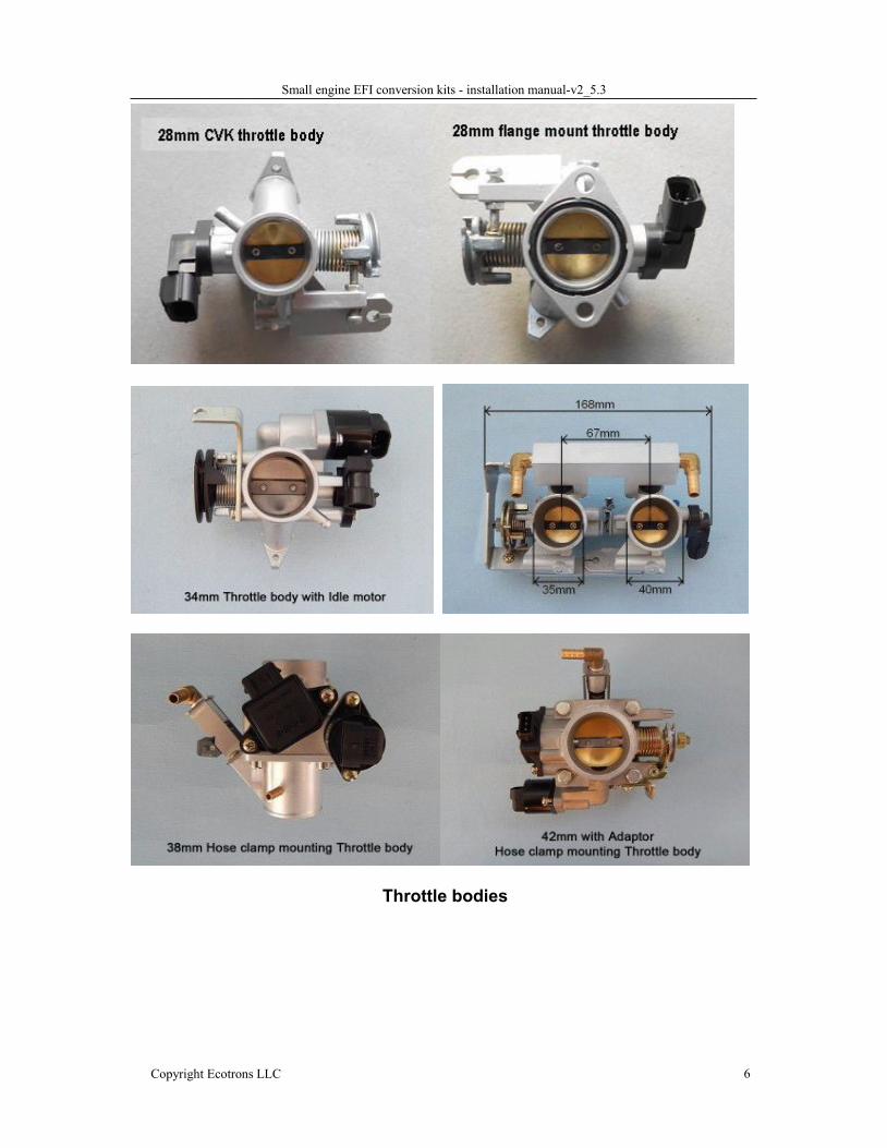
Throttle bodies
Small engine EFI conversion kits - installation manual-v2_5.3
Copyright Ecotrons LLC 7
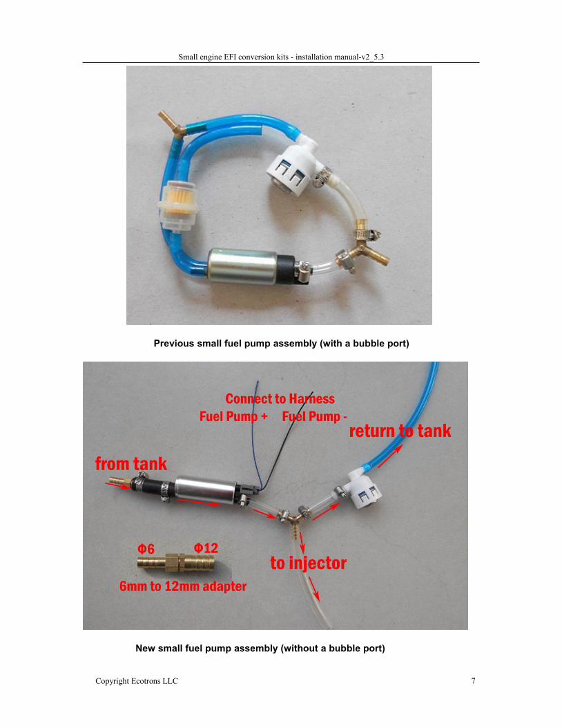
Previous small fuel pump assembly (with a bubble port)
New small fuel pump assembly (without a bubble port)
Small engine EFI conversion kits - installation manual-v2_5.3
Copyright Ecotrons LLC 8
Prerequisites for conversions
Questions to be answered before you decide to orderan EFI kit:
1. What is your engine displacement?
You need to tell us your engine displacement when you order the kit
because that determines the sizes of most components.
So far our EFI kits can convert engines in the range of 35cc all the way up
to 1200cc engines, single cylinder engines or 2-cylinder engines; parallel
twin or V-twin engines.
We are also capable of developing customer kits for 3 or 4 cylinder EFI kits.
The EFI kits can be categorized in the below classes:
35cc to 110cc engines: many scooter engines are in this range,
typically GY6 style, or horizontal style engine. For this type of
engine, you may use our 28mm throttle body with an adapter, or a
hose clamp to install. The injector is mounted on the throttle body.
125cc / 150cc to 200cc engines: for GY6 style or monkey bikes;
dirt bikes, etc. You may use our 28mm throttle body (TB), either
hose mounting or flange mounting styles. The injector is mounted
on the TB. No intake manifold is included.
250cc to 400cc engines: (single cylinder engines), you may use
our 34mm TB, with a built-in idle air motor (IAC); the injector is
mounted on the TB.
400cc to 800cc engines (single cylinder): you may use our 38mm,
42mm, 45mm, 50mm, or even 60mm TBs. Note, only 38mm and
42mm TBs have the injector mount built in the intake manifold
adaptor; other TBs you may need to get your own intake manifold
Small engine EFI conversion kits - installation manual-v2_5.3
Copyright Ecotrons LLC 9
or injector mounts;
250cc to 1500cc 2-cylinder engines (V-twin or parallel twin):This category covers a wide range of different engines. Some
engines we have done the conversion and it's kind of PNP kit
already, for example, Kawasaki Ninja 250r kits. We have also done
many customer conversion kits. You are welcome to contact us to
co-develop some kits for your applications.
3-cylinder or 4-cylinder engines: this category is very customerspecific applications. Contact us for details.
2. What is the current ignition system on your engine?You can either keep your existing ignition system if you like it, or you can useour ECU controlled ignition system, which are optional for some engines.
CDI ignition system
Our ECU needs a timing input from your existing ignition system. The typical
timing input we use is the pickup of your stock CDI ignition system.
Most small engine CDI systems use a small pickup coil as the trigger to fire
the CDI. This is the first and the easiest option for our ECU timing input (CKP
wire, or Crank Position sensor).
Most CDI systems use a pickup that only generates one pulse perrevolution. That is the default input to our ECU CKP.
Some engines have a pickup that generates 2 pulses per revolution. You need
to tell us when you order a kit. Our ECU can handle 2 pulses per rev, or even
multiple pulses per rev. But the pre-loaded software will be a little different.
TCI Integrated ignition coil system
TCI stands for transistorized charging ignition system. Many small engines,
like Honda GX series, as GX35, GX200, GX390 ect; Briggs & Stratten
engines; have an integrated ignition coil installed next to the flywheel; and use
Small engine EFI conversion kits - installation manual-v2_5.3
Copyright Ecotrons LLC 10
a magnet to trigger the coil and fire the spark plug directly, there is no CDI, or
standalone ignition coil. There is no dedicated pickup signal of this type of
ignition system.
For some of these engines, the kill switch wire from the ignition coil can be
used as the pickup. See details later. But for some other engines, this wire
has too much noise that can NOT be used as the pickup. Contact us to
confirm.
If you don’t have a pickup, or if you want to use our ECU to control the ignition,
you may use 3 of our components to replace this one integrated ignition coil,
namely: Hall-effect sensor, CDI, and a coil.
The Hall-effect sensor acts like a pickup; it shall be installed at the same
location as the stock ignition coil. A bracket may be needed; the CDI is driven
by our ECU; and our coil is driven by our CDI, and the coil drives the spark
plug. It seems more complicated, but the benefits are the fully controlled
ignition system, you can program the ignition maps as you want!
Mechanical break-point style ignition system
There are still a lot of vintage engines that are running on break-point style
ignition systems. In this case you may have to convert it to electrical ignition
system. You want to convert it anyway, since it may already have created a lot
of headache to you. There are 2 ways to convert this type of ignition system:
Convert it to CDI system: good for single engines; you need to install a
magnet on the flywheel, or somewhere that makes sense; and install
our Hall effect sensor to be triggered by the magnet; then our CDI and
coil will be controlled by our ECU;
Convert it to high-tooth trigger wheel: good for 2/3/4 cylinder engines;
you need to install a multi-tooth trigger wheel, like 12-1, 24-1, 36-2; or
even 60-2 tooth wheels; and then install a VR type sensor (we can
provide); then our ECU will control our inductive coils directly and fire
Small engine EFI conversion kits - installation manual-v2_5.3
Copyright Ecotrons LLC 11
the spark plugs, like most modern cars! This is the best solution
though most efforts!
3 or 4-cylinder ignition system
Either you keep your stock ignition system. Just provide a pickup to
ECU. ECU will control fuel only.
Or you install a high-tooth trigger wheel. Our ECU can drive inductive
coils directly. Its better, it more efficient, and it's the right way.
3. What is the RPM range of your engine?The RPM range for a 2 stroke engine is critical! Because it determines
whether you need 1 or 2 injectors per cylinder, and that drives different
hardware and the prices.
For 2-stroke engines that run less than 10k RPM, one injector is enough;
for engines of 12k RPM or higher, 2 injectors are needed. Between
10k to 12k RPM, you need to confirm with us.
4. Do you want to turbo charge your engine?If you have a turbo installed on your engine, please order the turbo EFI kit,
which will come with a 2.5bar MAP sensor, and a bigger injector for the
boost pressure and more power.
We do carry a small engine turbo, VZ21, similar to RHB31 turbo. Check it
out at our website.
5. Power supply: 12V battery and charging systemThe EFI kit needs 12V power supply. It means by default, a 12v battery is
needed. It also requires the charging system to maintain the 12V power. The EFI
system power consumption is about 40W to 80W dependent on different sizes of
EFI components. The stock charging system must provide enough power to run
Small engine EFI conversion kits - installation manual-v2_5.3
Copyright Ecotrons LLC 12
both stock electrical system and the EFI system.
We do have a battery-less EFI system, but it requires an even stronger
12V charging system to start and maintain the engine running. And this system is
usually customer specific and it is more expensive.
Most stock charging system provides 80W or more charging power and it
has enough buffering to add the EFI system. The only problem is with the
extended long idle, like more than 10-minute idle. Long idle will drain you battery
for some small charging systems.
Usually the smaller the engine size, the smaller the charging power is.
How do you find out whether your charging system is enough or not?If you run your engine as regular driving, not just idling, and your 12v battery
is less than 13V when the engine is running, you have the charging deficiency!
We have found, in general, any engine that is 150cc or bigger should have
enough charging power for our EFI system.
The biggest “consumer” of electrical power in the EFI system is the fuel
pump. We have 4 sizes of the fuel pumps:
1) Small fuel pump: 25L/H flow rate, support engine sizes from 50cc to
400cc. It draws 2A current in average, which is equivalent to 30W.
2) Medium fuel pump: 45L/H flow rate, support engine sizes from
400cc to 1200cc. It draws 3A current in average, which is equivalent
to 45W.
3) Large fuel pump: 120L/H flow rate, support engine sizes 1000cc up.
It draws 5A current in average, which is equivalent to 70W.
4) Mini plunge type fuel pump, controllable flow rate, max 10L/h,
current draw 1A average; support engine sizes of 10cc to 125cc.
This type of fuel pump is only available for small OEMs and it is
customer specific.
Other electrical power consumers include injectors, ignition coils, relays,
O2 sensors, etc. Adding together, the EFI power consumption would be in 40W to
80W range.
Small engine EFI conversion kits - installation manual-v2_5.3
Copyright Ecotrons LLC 13
Usually the super small engines (50cc or below) would have charging power
deficiency. For example, a 50cc scooter engine, the stock charging system usually
provides about 80W power in total. After the stock electrical system, like the head
lamp, and the brake lamp, takes the power, there is not enough power left for EFI.
For this case, there are 2 ways to fix it:
1) Change all your lamps to LED lamps. This saves enough power for EFI.
This has been proved an efficient way.
2) Upgrade your charging system. For example, the stock stator is only 6
poles or 8 poles. You can buy an aftermarket stator with 12 poles or even
18 poles etc. If you are really good at electrical staff, you can upgrade the
stock rectifier from the half-wave to full-wave which theoretically doubles
the stator output.
Some engines do not have a meaningful charging system. For example,
some small 2 stroke engines, and some racing engines, which only have a
few charging coils to provide the power to the ignition system. There is no
meaningful 12V DC charging power. There is no lamp used with these
applications. In this case, you must upgrade the charging system for EFI
system.
Some people want to run the EFI with just a battery pack, like a Lithium
battery. It is do-able if you only run your engine for an hour, for example,
but it’s not preferred. The issue is once the battery starts to be lower than
12V, the fuel supply system will not maintain the enough fuel pressure (3 bar)
and your engine could run lean and unstable.
For many installations, after you installed the EFI system and tried to crank a
few times, your battery can be drained already. The best way is to put a
charger on the 12V battery to trouble shooting starting issues.
Also, if you have leaved your engine off for a long time, the chance that your
battery is low is high. You better charge your 12v battery before you run your
Small engine EFI conversion kits - installation manual-v2_5.3
Copyright Ecotrons LLC 14
engine again. Or at least put the charger on during the engine start.
Last but not the least, when you try to program the ECU or burn the new
calibration data into ECU, you better make sure the battery is not low before
you do that. Low battery can leave your ECU half-way programmed and
basically brain dead. You need to put the charger on, and re-program it to
100% completed.
You can use a voltage meter to measure the voltage of the battery. The value
should be higher than 12V when engine is not running, and it should be higher
than 13v when the engine is running.
You can also use ProCAL (laptop or Droid phone app), to read the battery
voltage:
Power on ECU and connect to ECU. Go to menu "Variables->Display
Type->List". Then "Run->Start measuring"
“UbAdc” is the battery voltage read by the ECU.
6. Fuel supply systemThe fuel supply system must be installed correctly to provide the fuel to
injector, and maintain the fuel pressure. If the fuel supply system is not installed
correctly, you could have fuel starving issue, showing as some erratic problems,
or not able to start the engine at all.
1) The fuel pump must be installed below the fuel tank; or at least at the
bottom level of the fuel tank, because the fuel pump does not have
enough sucking power, it could be starving if it is located higher than
the tank.
2) The fuel pressure regulator must be connected correctly (inlet vs
outlet). Or you will not get any fuel pressure.
3) The fuel return line must be routed back to fuel tank correctly,
otherwise you could have air bubbles in the fuel supply system, and
not able to provide the fuel to the injector.
Small engine EFI conversion kits - installation manual-v2_5.3
Copyright Ecotrons LLC 15
A normal fuel supply system installation, after you key cycle a few times,
should show that the fuel flows from tank to the fuel pump, then through the
pressure regulator and then the fuel return line and back to the tank. You
shall hear fuel pump turning on for a few seconds every time you key on, and
see fuel flowing back to the tank, and no bubbles in the fuel lines.
Note: Sometime, you have to manually purge out all the air bubbles in the fuel
supply system, because it is possible that if the fuel pump itself has a lot bubbles
in there, it could not pump fuel at all, it is only spinning like idle without load. In this
case the noise of fuel pump is little higher pitch than with fuel pumping. In this
case you will not be able to start no matter what, because no fuel pumping. If you
have any doubt that the fuel supply system has some air pocket or air bubbles,
you can un-plug the high pressure fuel line, pointing it into a bottle, and key-on,
you should see fuel sprout out if fuel pump is working and no air bubbles."
For the detail of fuel pump installation, please read the followinginstallation details.
Small engine EFI conversion kits - installation manual-v2_5.3
Copyright Ecotrons LLC 16
Installation Procedures
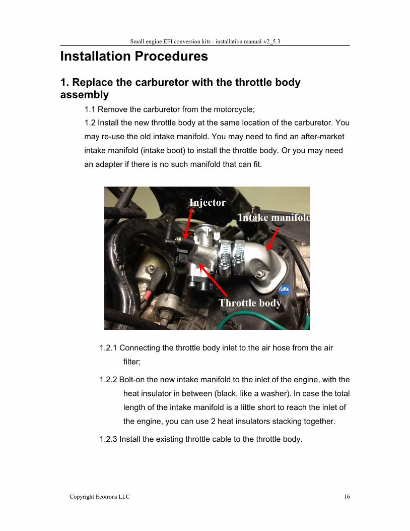
1. Replace the carburetor with the throttle bodyassembly
1.1 Remove the carburetor from the motorcycle;1.2 Install the new throttle body at the same location of the carburetor. You
may re-use the old intake manifold. You may need to find an after-market
intake manifold (intake boot) to install the throttle body. Or you may need
an adapter if there is no such manifold that can fit.
1.2.1 Connecting the throttle body inlet to the air hose from the air
filter;
1.2.2 Bolt-on the new intake manifold to the inlet of the engine, with the
heat insulator in between (black, like a washer). In case the total
length of the intake manifold is a little short to reach the inlet of
the engine, you can use 2 heat insulators stacking together.
1.2.3 Install the existing throttle cable to the throttle body.
Injector
Throttle body
Intake manifold
Small engine EFI conversion kits - installation manual-v2_5.3
Copyright Ecotrons LLC 17
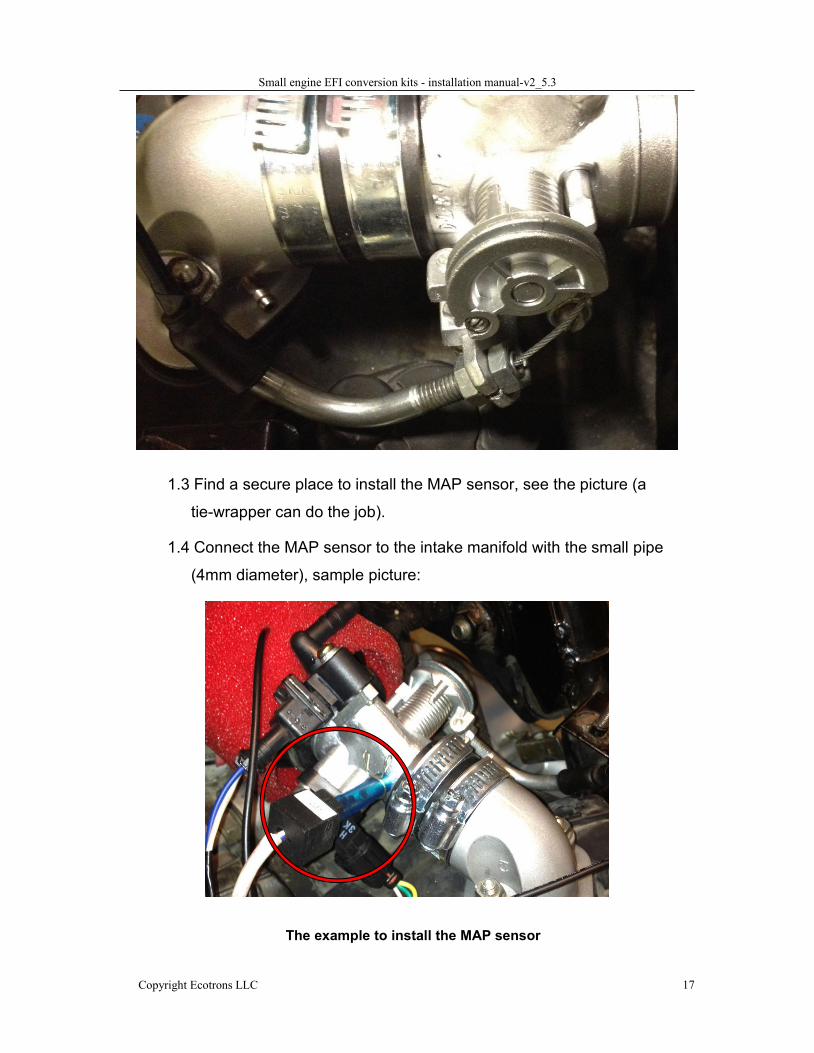
1.3 Find a secure place to install the MAP sensor, see the picture (a
tie-wrapper can do the job).
1.4 Connect the MAP sensor to the intake manifold with the small pipe
(4mm diameter), sample picture:
The example to install the MAP sensor
Small engine EFI conversion kits - installation manual-v2_5.3
Copyright Ecotrons LLC 18
Map sensor installation
For 4 stroke engines, you need to connect the MAP sensor to the intake manifold.
And the intake manifold is sealed and air tight; MAP sensor must read the vacuum
during engine start process.
Incorrect installation of the MAP sensor can cause not-able-to-start engine, or it
can short the MAP sensor life.
Note: Important Notes for installation of the MAP sensor:
Connect the Map sensor to the manifold or the throttle body (downstream
of the throttle pate), and make sure it is air tight! MAP sensor is meant to
measure the pressure between the throttle plate and the intake valve.
You need a short hose to connect; less than 2 inches or 5cm long, no
longer than 4 inches or 10cm. Too long a hose can cause some deviation
of the sensor reading.
The MAP sensor should not be too closed to the engine block. Air cooled
engine block can get to 200 degree C which is much higher than the MAP
sensor working temperature. This can damage the Map sensor.
MAP sensor itself is not fuel proof. You shall avoid fuel getting into the MAP
sensor chamber. This means you shall install the MAP sensor on top of the
throttle body or manifold, so that the gravity will pull the fuel down to the
manifold, in case the fuel gets into the tube.
Make sure the MAP sensor hose is not severely bent, or not routed in circle;
otherwise a pocket could be created and the fuel puddle gets stuck there.
Fuel puddle could also get into the MAP sensor and damage it.
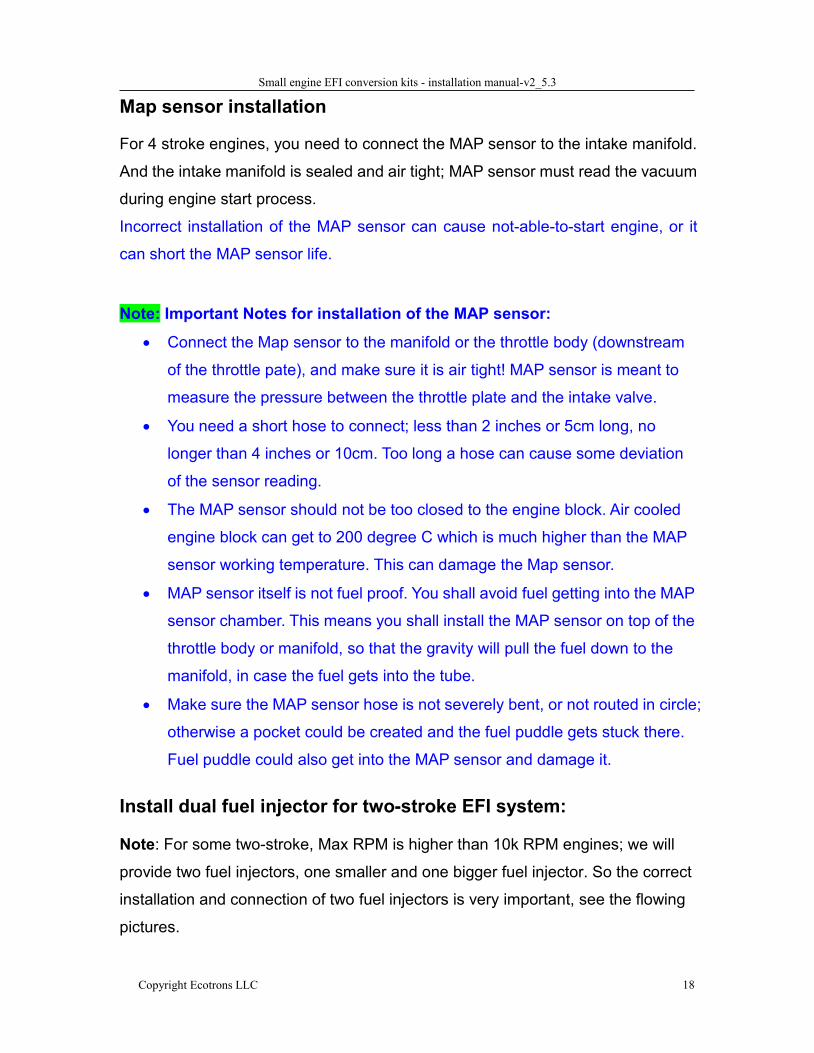
Install dual fuel injector for two-stroke EFI system:
Note: For some two-stroke, Max RPM is higher than 10k RPM engines; we will
provide two fuel injectors, one smaller and one bigger fuel injector. So the correct
installation and connection of two fuel injectors is very important, see the flowing
pictures.
Small engine EFI conversion kits - installation manual-v2_5.3
Copyright Ecotrons LLC 19
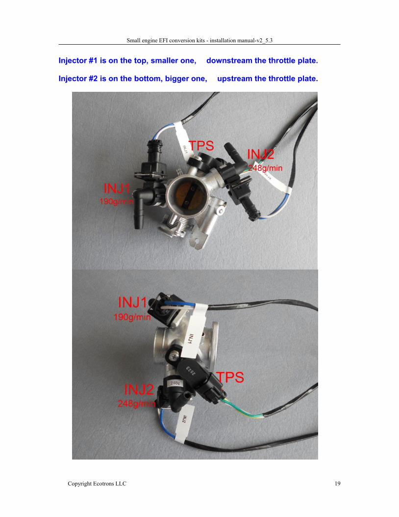
Injector #1 is on the top, smaller one, downstream the throttle plate.
Injector #2 is on the bottom, bigger one, upstream the throttle plate.
Small engine EFI conversion kits - installation manual-v2_5.3
Copyright Ecotrons LLC 20
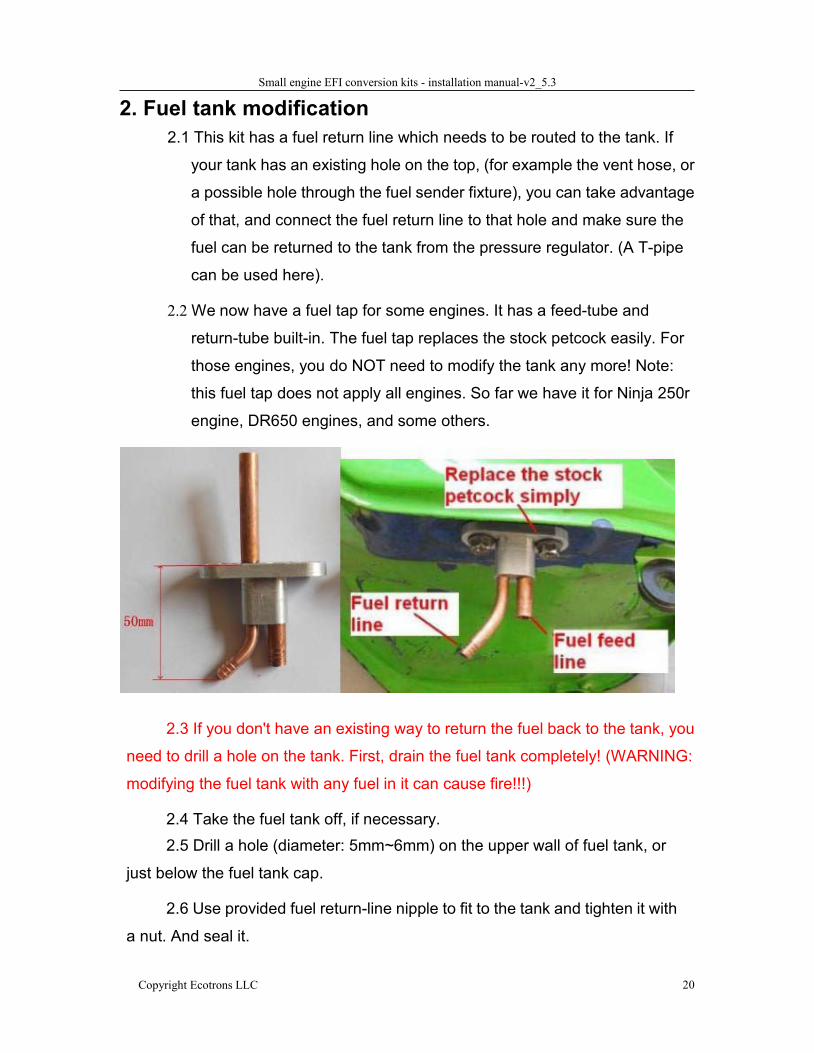
2. Fuel tank modification2.1 This kit has a fuel return line which needs to be routed to the tank. If
your tank has an existing hole on the top, (for example the vent hose, or
a possible hole through the fuel sender fixture), you can take advantage
of that, and connect the fuel return line to that hole and make sure the
fuel can be returned to the tank from the pressure regulator. (A T-pipe
can be used here).
2.2We now have a fuel tap for some engines. It has a feed-tube and
return-tube built-in. The fuel tap replaces the stock petcock easily. For
those engines, you do NOT need to modify the tank any more! Note:
this fuel tap does not apply all engines. So far we have it for Ninja 250r
engine, DR650 engines, and some others.
2.3 If you don't have an existing way to return the fuel back to the tank, you
need to drill a hole on the tank. First, drain the fuel tank completely! (WARNING:
modifying the fuel tank with any fuel in it can cause fire!!!)
2.4 Take the fuel tank off, if necessary.2.5 Drill a hole (diameter: 5mm~6mm) on the upper wall of fuel tank, or
just below the fuel tank cap.
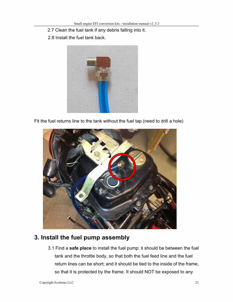
2.6 Use provided fuel return-line nipple to fit to the tank and tighten it with
a nut. And seal it.
Small engine EFI conversion kits - installation manual-v2_5.3
Copyright Ecotrons LLC 21
2.7 Clean the fuel tank if any debris falling into it.2.8 Install the fuel tank back.
Fit the fuel returns line to the tank without the fuel tap (need to drill a hole)
3. Install the fuel pump assembly3.1 Find a safe place to install the fuel pump: it should be between the fuel
tank and the throttle body, so that both the fuel feed line and the fuel
return lines can be short; and it should be tied to the inside of the frame,
so that it is protected by the frame. It should NOT be exposed to any
Small engine EFI conversion kits - installation manual-v2_5.3
Copyright Ecotrons LLC 22
external scratch or bump. It should not touch the ground when the
motorcycle lies on the ground.
3.2 Connect the fuel feed line from the fuel tank outlet to the inlet of the
fuel filter (fuel filter, by default, has been connected to the inlet of the
fuel pump).
3.3 Connect the high pressure fuel lines from the fuel pump to the fuel
injector, which is located on the intake manifold or throttle body.
3.4 Connect the fuel-return line to the T-pipe. The T-pipe, by default,
merges the fuel bubble line and the fuel pressure regulator return line
together and then returns the fuel to the tank.
3.5 Secure all fuel lines with supplied clamps, make sure no leak.
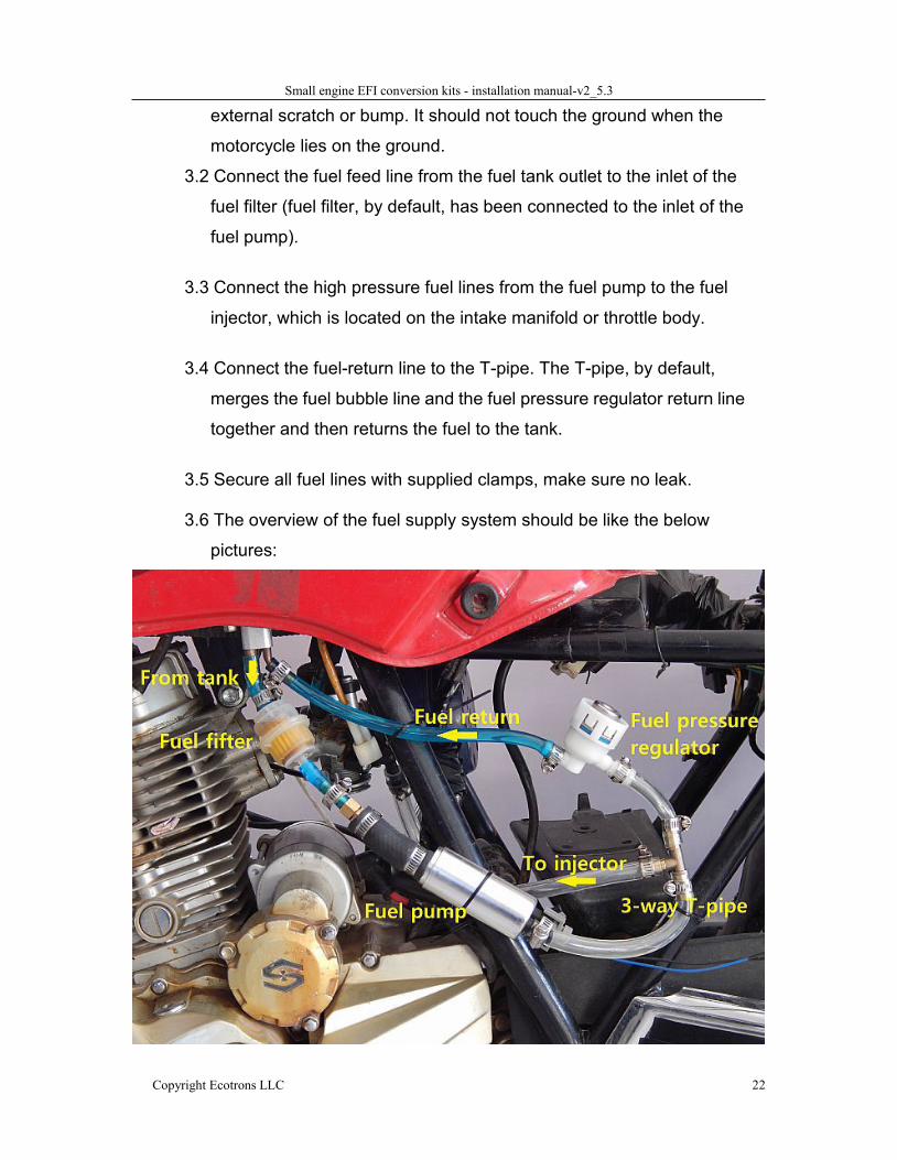
3.6 The overview of the fuel supply system should be like the below
pictures:
Small engine EFI conversion kits - installation manual-v2_5.3
Copyright Ecotrons LLC 23
See Appendix I (Fuel supply system schematics)
Note: The correct order of fuel supply components should be (from high to low
locations):
Tank fuel filter Fuel Pump
The fuel pump must be lower than the lowest point of the fuel tank.
Some fuel tanks have a tank valve which requires the vacuum from the
intake manifold to open, called "petcock". In this case, you need to
replace it with a simpler valve that does not require vacuum, and you can
open and close it manually. Or if your petcock valve has a "Prime" position,
that does not require vacuum, and set it to "PRI" position.
Note: Please use the fuel hose which is from EFI kits as possible, if you
use your own the black rubber fuel hose, it may produce debris while
installing and uninstalling the rubber fuel hose, then the fuel injector may
be blocked, this will affect the performance.
Small engine EFI conversion kits - installation manual-v2_5.3
Copyright Ecotrons LLC 24
Fuel Pump wire connectionThere are mainly 2 sizes of fuel pumps supplied by Ecotrons, Small size and
medium size.
(We now have a mini-size plunge fuel pump, for engines of 25cc to 80cc range.
Contact for details).
Small fuel pump has a flow rate of 25L/H, it is suitable for 150cc, 250cc, up to
400cc engines. It may also run with smaller engines like 50cc, with some excess.
Medium pump has a flow rate of 45L/H, and it is suitable for 400cc up, like 650cc,
800cc and even 1100cc engines.
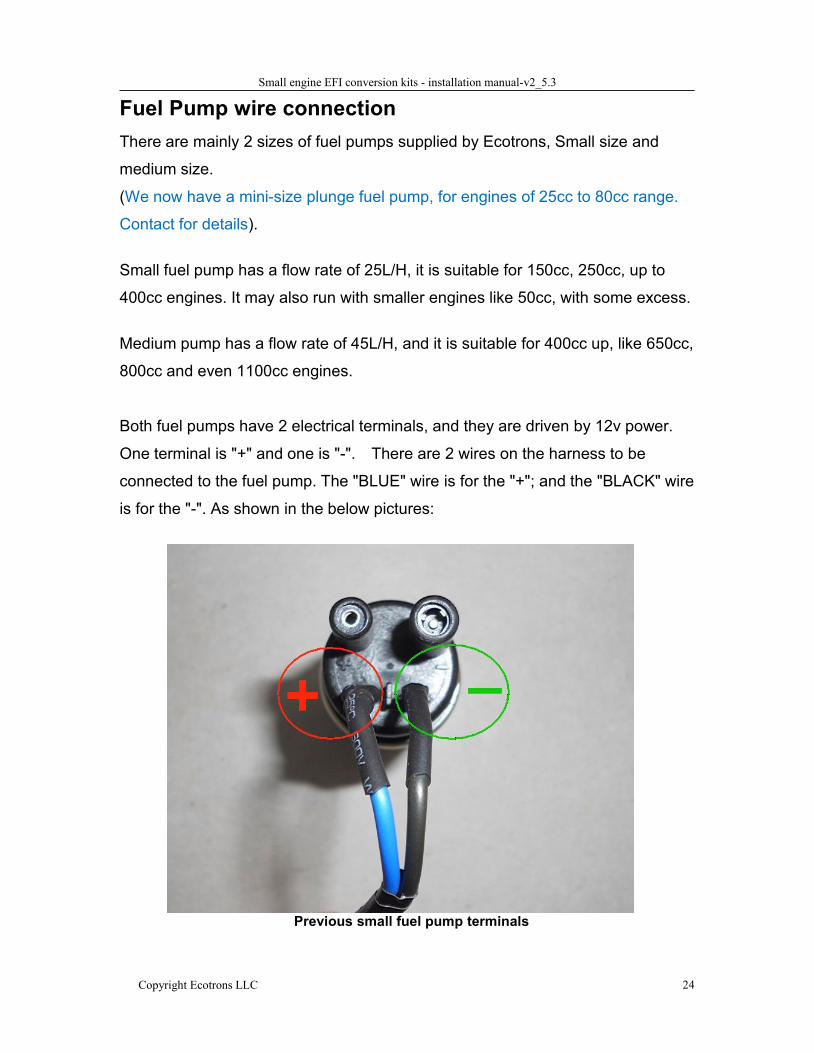
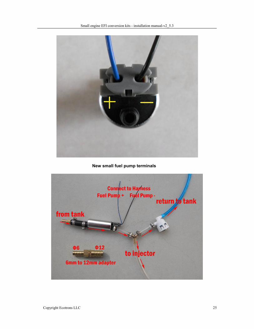
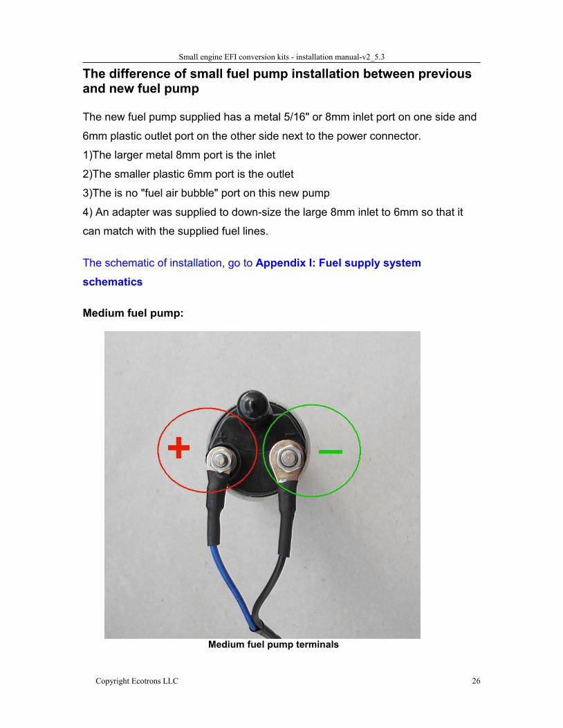
Both fuel pumps have 2 electrical terminals, and they are driven by 12v power.
One terminal is "+" and one is "-". There are 2 wires on the harness to be
connected to the fuel pump. The "BLUE" wire is for the "+"; and the "BLACK" wire
is for the "-". As shown in the below pictures:
Previous small fuel pump terminals
Small engine EFI conversion kits - installation manual-v2_5.3
Copyright Ecotrons LLC 25
New small fuel pump terminals
Small engine EFI conversion kits - installation manual-v2_5.3
Copyright Ecotrons LLC 26
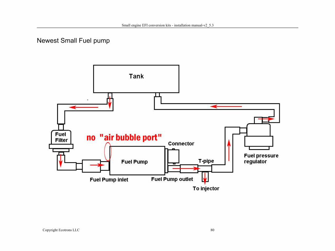
The difference of small fuel pump installation between previousand new fuel pump
The new fuel pump supplied has a metal 5/16" or 8mm inlet port on one side and
6mm plastic outlet port on the other side next to the power connector.
1)The larger metal 8mm port is the inlet
2)The smaller plastic 6mm port is the outlet
3)The is no "fuel air bubble" port on this new pump
4) An adapter was supplied to down-size the large 8mm inlet to 6mm so that it
can match with the supplied fuel lines.
The schematic of installation, go to Appendix I: Fuel supply systemschematics
Medium fuel pump:
Medium fuel pump terminals
Small engine EFI conversion kits - installation manual-v2_5.3
Copyright Ecotrons LLC 27
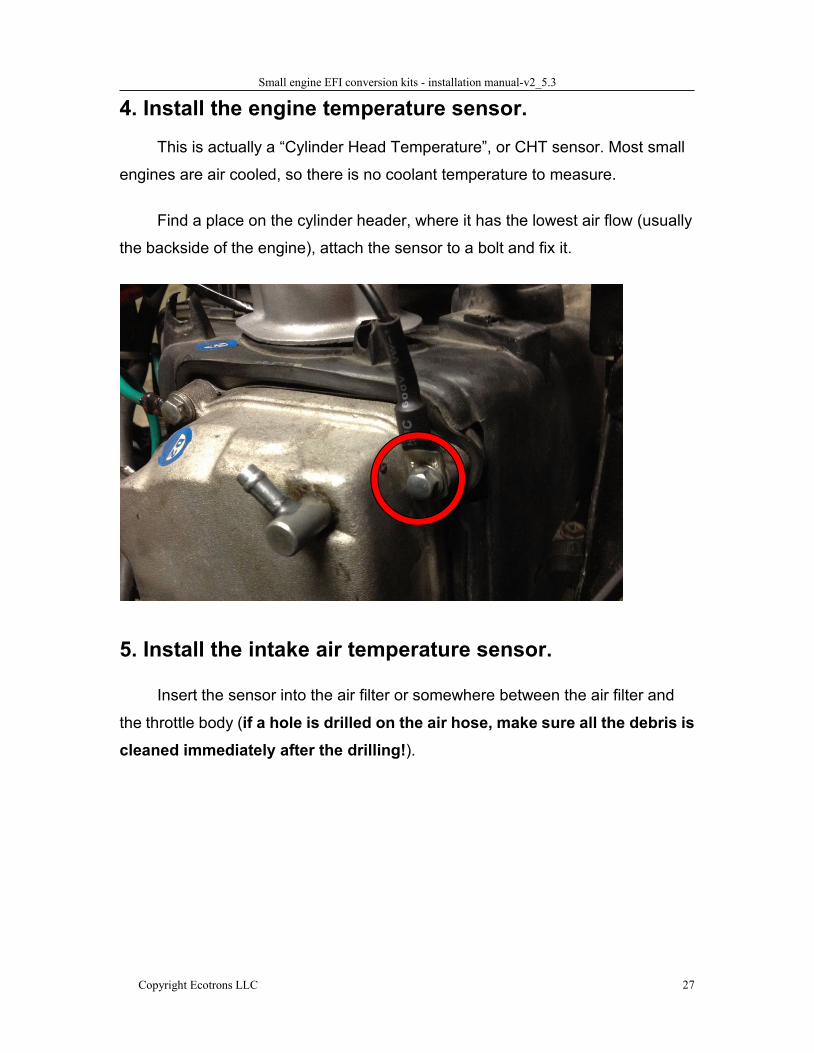
4. Install the engine temperature sensor.
This is actually a “Cylinder Head Temperature”, or CHT sensor. Most small
engines are air cooled, so there is no coolant temperature to measure.
Find a place on the cylinder header, where it has the lowest air flow (usually
the backside of the engine), attach the sensor to a bolt and fix it.
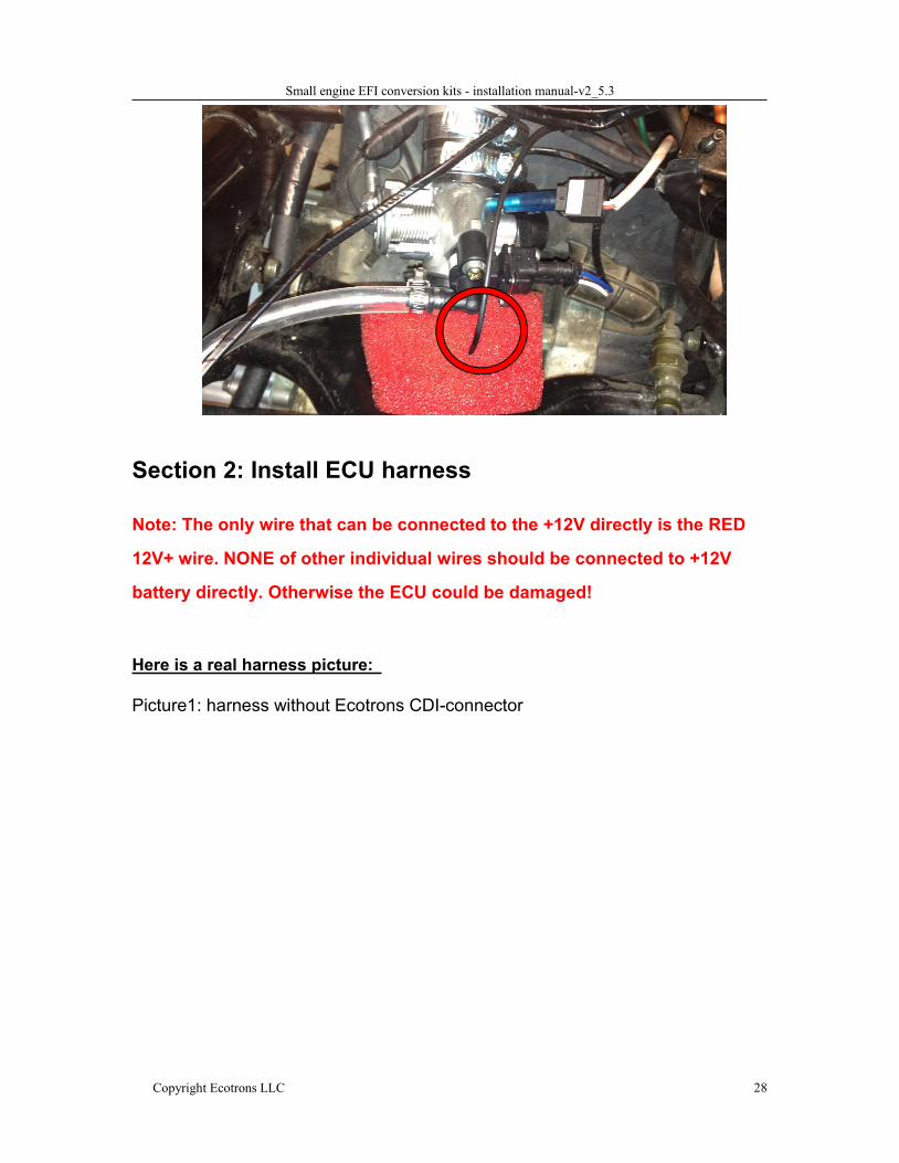
5. Install the intake air temperature sensor.
Insert the sensor into the air filter or somewhere between the air filter and
the throttle body (if a hole is drilled on the air hose, make sure all the debris iscleaned immediately after the drilling!).
Small engine EFI conversion kits - installation manual-v2_5.3
Copyright Ecotrons LLC 28
Section 2: Install ECU harness
Note: The only wire that can be connected to the +12V directly is the RED
12V+ wire. NONE of other individual wires should be connected to +12V
battery directly. Otherwise the ECU could be damaged!
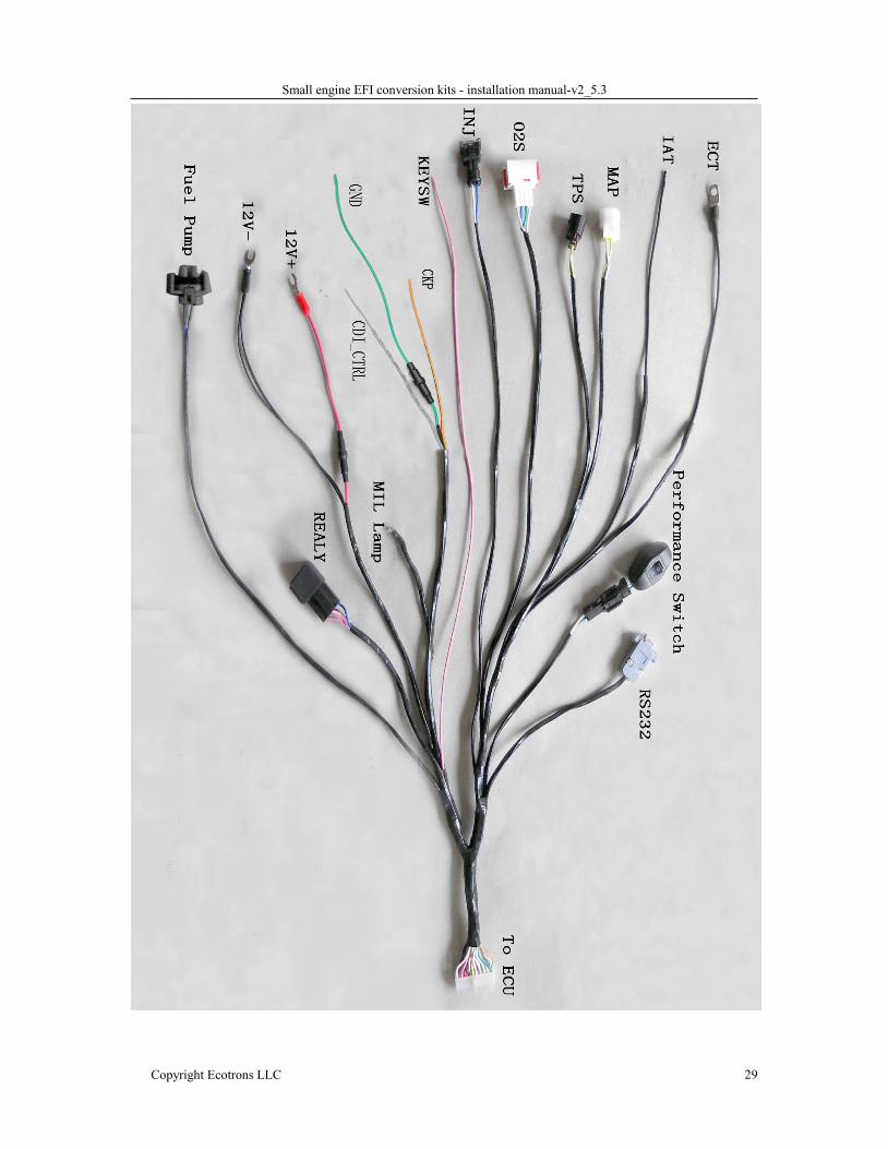
Here is a real harness picture:
Picture1: harness without Ecotrons CDI-connector
Small engine EFI conversion kits - installation manual-v2_5.3
Copyright Ecotrons LLC 29
Small engine EFI conversion kits - installation manual-v2_5.3
Copyright Ecotrons LLC 30
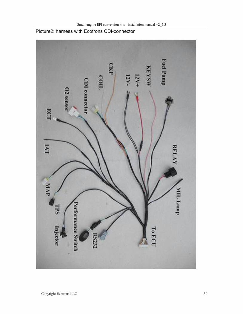
Picture2: harness with Ecotrons CDI-connector
Small engine EFI conversion kits - installation manual-v2_5.3
Copyright Ecotrons LLC 31
Harness label descriptions
Note: the wire color scheme may be different for old versions.If your harness looks different than the one in the picture,please contact us for exact wiring info.
Note: some abbreviations and gloss have been changedCompared to previous versions:CKP = VRSCDI-Ctrl = CDI-PGGND = AGNDKEYSW = IGNSWIGN=COIL
label Descriptions NotesECU Electronic Control UnitRS232 Serial comm.cable to a PC computerO2S Oxygen sensor
Fuel Pump Fuel pump power and ground12V- Battery 12V-12V+ Battery 12V+IAT Intake Air Temperature sensorECT Engine (Coolant) Temperature sensor
Performanceswitch
Manual switch to select fuel tables: ECOmode vs. Rich mode
TPS Throttle position sensorMAP Manifold absolute pressureINJ InjectorCKP Crank Position sensor Connect to
Ignition pickup wire (also called VRS before)Orange
CDI-Ctrl CDI control output from ECU (also calledCDI-PG before)
Gray
GND Ground (previously called Analog Ground) GreenKEYSW Key On switch (previously called IGNSW) Pink
Small engine EFI conversion kits - installation manual-v2_5.3
Copyright Ecotrons LLC 32
6. Pickup sensor / Crank Position SensorWhy EFI needs a pick-up sensor?
SAE name of the pickup is CKP (CranK Position Sensor).
Crank-shaft pick-up input is the most important for EFI system. It tells the
ECU the engine timing, or TDC position. The ECU uses it to calculate the RPM;
and it also uses it to trigger the fuel injection once per cycle, and to command the
spark at the specific crankshaft angle.
Without the correct pickup (or CKP input), EFI will NOT work, period.There are a few types of pickups our EFI can work with.
Depending on what type of ignition system you have with your engine, our EFI
can use the below types of the pickups:
CDI ignition pickup
TCI ignition kill wire
Hall effect sensor pickup
Multi-tooth trigger wheel crank sensor
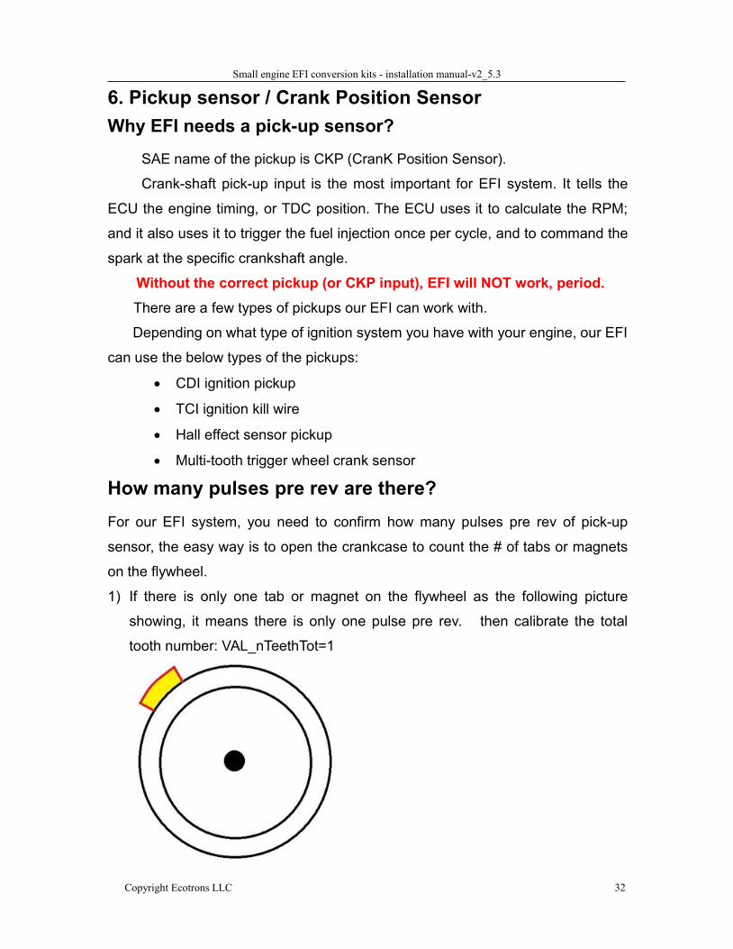
How many pulses pre rev are there?For our EFI system, you need to confirm how many pulses pre rev of pick-up
sensor, the easy way is to open the crankcase to count the # of tabs or magnets
on the flywheel.
1) If there is only one tab or magnet on the flywheel as the following picture
showing, it means there is only one pulse pre rev. then calibrate the total
tooth number: VAL_nTeethTot=1
Small engine EFI conversion kits - installation manual-v2_5.3
Copyright Ecotrons LLC 33
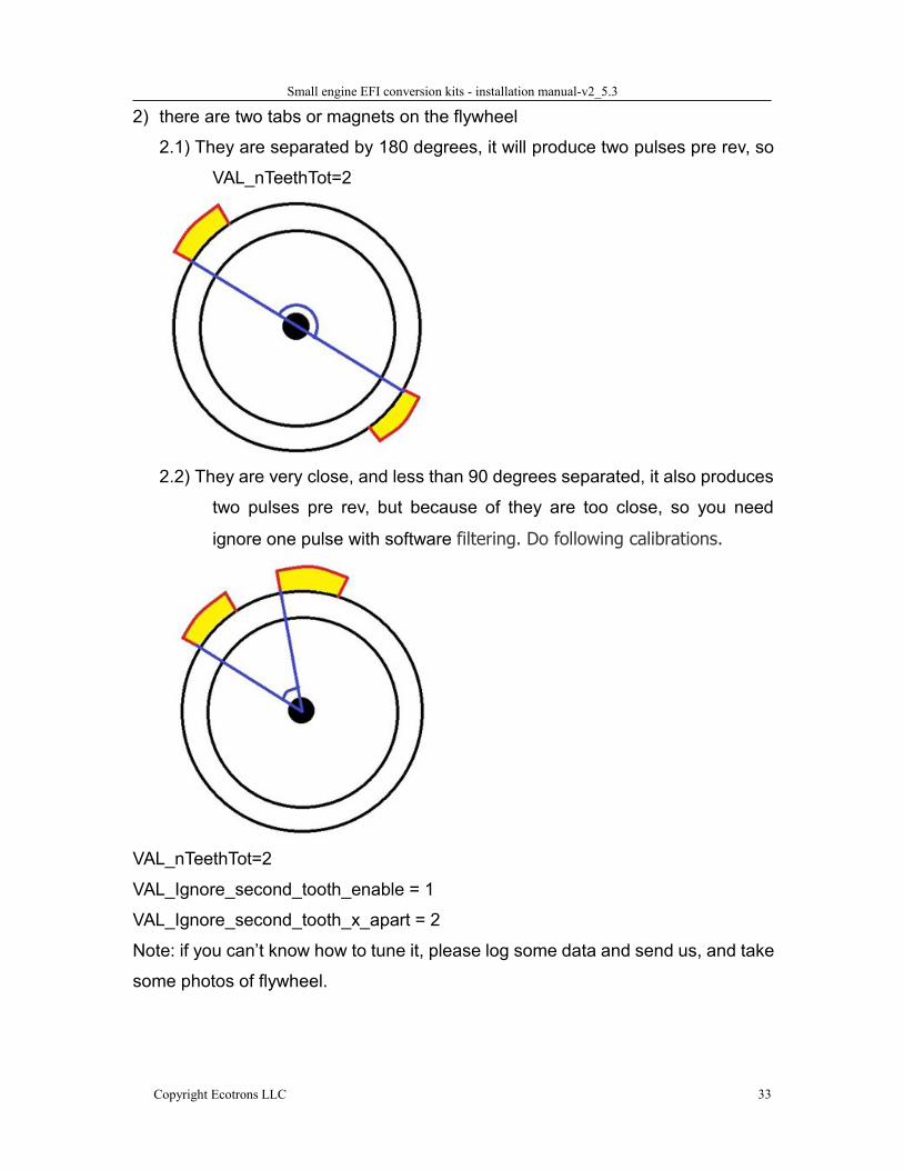
2) there are two tabs or magnets on the flywheel
2.1) They are separated by 180 degrees, it will produce two pulses pre rev, so
VAL_nTeethTot=2
2.2) They are very close, and less than 90 degrees separated, it also produces
two pulses pre rev, but because of they are too close, so you need
ignore one pulse with software filtering. Do following calibrations.
VAL_nTeethTot=2
VAL_Ignore_second_tooth_enable = 1
VAL_Ignore_second_tooth_x_apart = 2
Note: if you can’t know how to tune it, please log some data and send us, and take
some photos of flywheel.
Small engine EFI conversion kits - installation manual-v2_5.3
Copyright Ecotrons LLC 34
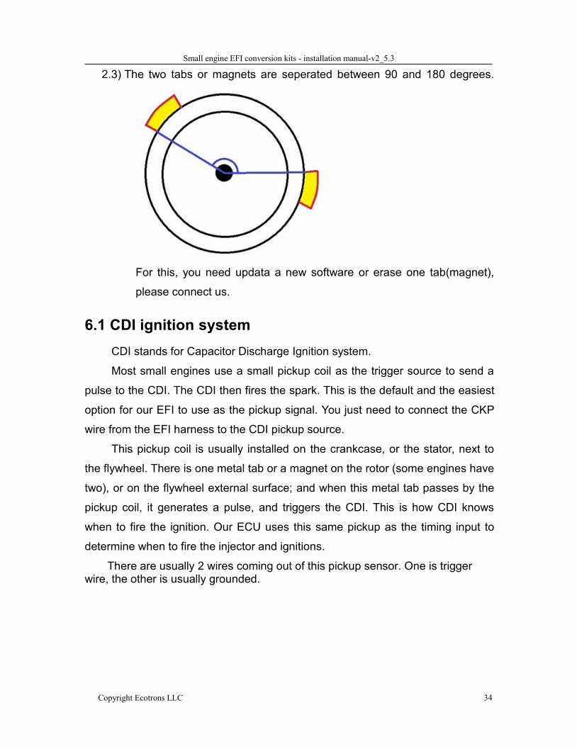
2.3) The two tabs or magnets are seperated between 90 and 180 degrees.
For this, you need updata a new software or erase one tab(magnet),
please connect us.
6.1 CDI ignition systemCDI stands for Capacitor Discharge Ignition system.
Most small engines use a small pickup coil as the trigger source to send a
pulse to the CDI. The CDI then fires the spark. This is the default and the easiest
option for our EFI to use as the pickup signal. You just need to connect the CKP
wire from the EFI harness to the CDI pickup source.
This pickup coil is usually installed on the crankcase, or the stator, next to
the flywheel. There is one metal tab or a magnet on the rotor (some engines have
two), or on the flywheel external surface; and when this metal tab passes by the
pickup coil, it generates a pulse, and triggers the CDI. This is how CDI knows
when to fire the ignition. Our ECU uses this same pickup as the timing input to
determine when to fire the injector and ignitions.
There are usually 2 wires coming out of this pickup sensor. One is triggerwire, the other is usually grounded.
Small engine EFI conversion kits - installation manual-v2_5.3
Copyright Ecotrons LLC 35
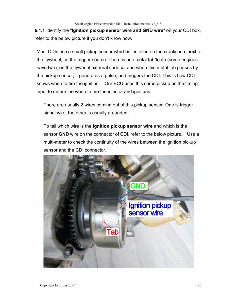
6.1.1 Identify the "Ignition pickup sensor wire and GND wire" on your CDI box,
refer to the below picture if you don't know how.
Most CDIs use a small pickup sensor which is installed on the crankcase, next to
the flywheel, as the trigger source. There is one metal tab/tooth (some engines
have two), on the flywheel external surface; and when this metal tab passes by
the pickup sensor, it generates a pulse, and triggers the CDI. This is how CDI
knows when to fire the ignition. Our ECU uses this same pickup as the timing
input to determine when to fire the injector and ignitions.
There are usually 2 wires coming out of this pickup sensor. One is trigger
signal wire, the other is usually grounded.
To tell which wire is the ignition pickup sensor wire and which is the
sensor GND wire on the connector of CDI, refer to the below picture. Use a
multi-meter to check the continuity of the wires between the ignition pickup
sensor and the CDI connector.
Small engine EFI conversion kits - installation manual-v2_5.3
Copyright Ecotrons LLC 36
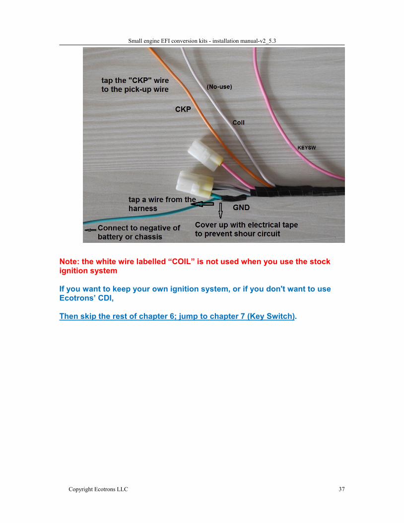
6.1.2 Tap the "Ignition pickup sensor wire" with the ECU CKP wire,
(Orange wire on the ECU harness); and then secure the splice with
electrical tape or better solder it. This wire is the ignition pickup signal (or
as we called it, the Crank Position sensor - also called VRS, variable
reluctant sensor, before);
6.1.3 Tap the "Ignition pickup sensor GND" with the ECU GND wire
(Green wire on the ECU harness). ). Note, some engines have only
one wire coming out of the pickup sensor, the ground wire is
connected to chassis internally. In this case, you need to connect ECU
GND wire (Green wire on the CDI connector) to the same chassis too.
Note, some engines have a CDI using both pickup “+” and Pickup “-“;
meaning none of the 2 pickup wires are grounded. In this case, you
need to figure out which one is the Pickup “+” and tap our CKP wire to
it. And connect the ECU GND wire (Green wire on the our CDI
connector) to chassis.
For many engines, which have their own special CDI, it is a good practice
NOT to use the Ecotrons CDI first, and get the engine running first with the
stock ignition system, and uses Ecotrons CDI later. Or you can simply keep
the stock ignition system and never install Ecotrons CDI, which reduce a
big variable here.
Small engine EFI conversion kits - installation manual-v2_5.3
Copyright Ecotrons LLC 37
Note: the white wire labelled “COIL” is not used when you use the stockignition system
If you want to keep your own ignition system, or if you don't want to useEcotrons’ CDI,
Then skip the rest of chapter 6; jump to chapter 7 (Key Switch).
Small engine EFI conversion kits - installation manual-v2_5.3
Copyright Ecotrons LLC 38
6.1.4 Use Ecotrons CDI
For some popular scooter engines like GY6 150cc engine, Ecotrons CDI is
compatible and can be installed immediately. This way Ecotrons EFI will
control both fuel and sparks. For those engines, the harness comes with
CDI connectors already in place.
If you want to use the EFI to control the CDI ignition timing, and if you
have Ecotrons CDI included in the kit, you need to do this: Cut the ignition
pickup sensor wire, and connect the wire from the sensor side to the ECU
CKP input (Orange wire on the harness).
Then connect the other side of the wire you just cut (which goes into the
CDI box) to the ECU CDI-Ctrl wire, (Gray wire on the ECU harness). (for
GY6 engines, see the picture below for this wire; some manufacturer
called it "sensor signal" on the CDI connector).
Note: if you use our ECU to control your own CDI, it may not work,contact us to confirm.
Note: if you use your own CDI, and if you don't know the pindefinitions on the CDI connector, DO NOT CONNECT CDI-Ctrl wire!Mis-connection of Pickup and CDI-Ctrl wires can damage the ECU.
Small engine EFI conversion kits - installation manual-v2_5.3
Copyright Ecotrons LLC 39
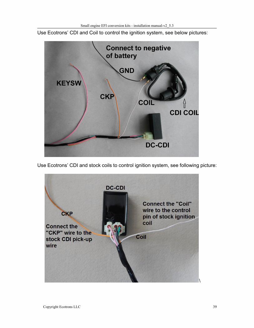
Use Ecotrons’ CDI and Coil to control the ignition system, see below pictures:
Use Ecotrons’ CDI and stock coils to control ignition system, see following picture:
\
Small engine EFI conversion kits - installation manual-v2_5.3
Copyright Ecotrons LLC 40
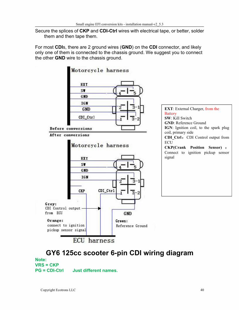
Secure the splices of CKP and CDI-Ctrl wires with electrical tape, or better, solderthem and then tape them.
For most CDIs, there are 2 ground wires (GND) on the CDI connector, and likelyonly one of them is connected to the chassis ground. We suggest you to connectthe other GND wire to the chassis ground.
EXT: External Charger, from theBatterySW: Kill SwitchGND: Reference GroundIGN: Ignition coil, to the spark plugcoil, primary sideCDI_Ctrl:CDI Control output fromECUCKP(Crank Position Sensor) :Connect to ignition pickup sensorsignal
GY6 125cc scooter 6-pin CDI wiring diagramNote:VRS = CKPPG = CDI-Ctrl Just different names.
Small engine EFI conversion kits - installation manual-v2_5.3
Copyright Ecotrons LLC 41
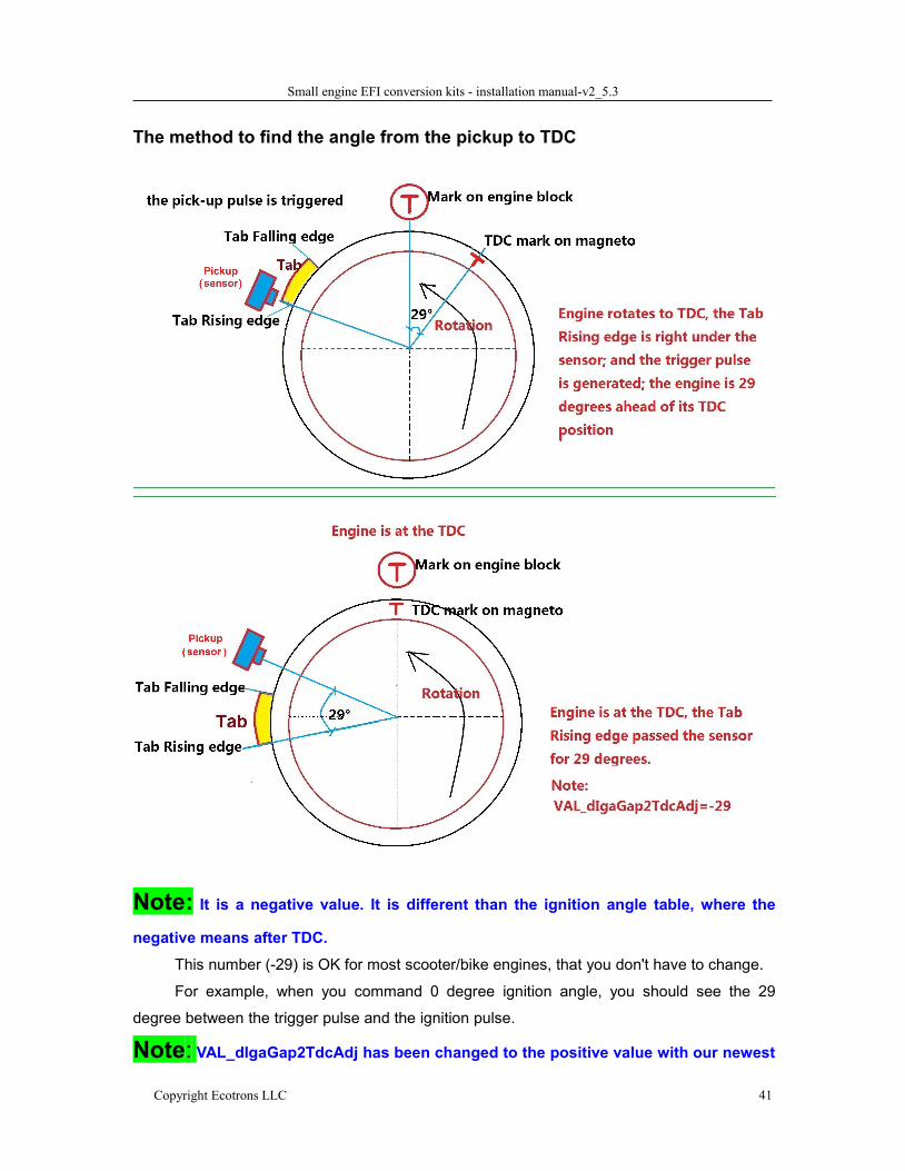
The method to find the angle from the pickup to TDC
Note: It is a negative value. It is different than the ignition angle table, where the
negative means after TDC.
This number (-29) is OK for most scooter/bike engines, that you don't have to change.
For example, when you command 0 degree ignition angle, you should see the 29
degree between the trigger pulse and the ignition pulse.
Note: VAL_dIgaGap2TdcAdj has been changed to the positive value with our newest
Small engine EFI conversion kits - installation manual-v2_5.3
Copyright Ecotrons LLC 42
software.
You can find out whether it should be a positive value with your A2L file, such
as:”S33_H1_L48_Cr17_AT3.4_E4.a2l” if the number is bigger than “Cr17”, for example, “Cr18
or Cr19….” it means it is the newer software, the VAL_dIgaGap2TdcAdj should be positive.
6.2 TCI ignition system
There are many engines that do not have a CDI. Instead, it has an integrated
ignition module, called TCI (Transistorized Charging Ignition) system. For
example, Honda GX200, GX390, etc. and Briggs & Stratton engines, those
engines have an ignition module installed right next to the flywheel. And there is a
magnet built in the flywheel. When the magnet passes by the ignition module, it
triggers the coil inside and fires the spark plug directly via a high voltage cable.
For this type of ignition system, there is no standalone pickup sensor. The only
wire that comes out of the ignition module is the kill wire.
This kill wire could be used as the pickup because it is basically connected to
the primary side of the coil. . The primary side of the coil will generate a big pulse
with some oscillations when the magnet passes by the coil. After all, when you
press the kill button, the kill wire is to ground the primary coil to suppress the
trigger pulse so the secondary coil does not fire at all.
As said, the kill wire can pass the trigger pulse from the primary coil to ECU,
but may do it with a lot of the noises. The noises are generated by the firing event
of the secondary coil. To use the kill wire signal as the CKP input, some intensive
filtering process is needed. The ECU has some built in filters to handle noises. In
most cases, it can handle the kill wire signal with noises. But because there are so
many different engines out there, some kill wire noises may not be filtered. In that
case, you can use a dedicated Hall-effect sensor as the pickup.
To do that, you need to confirm with us that you need a Hall-effect sensor, an
Ecotrons CDI, and an ignition coil from us. These 3 components will replace the
Small engine EFI conversion kits - installation manual-v2_5.3
Copyright Ecotrons LLC 43
stock integrated ignition module. You will need to install the Hall Effect sensor at
the same location of stock ignition module. It seems complicated. But it gives the
ECU the critical pickup input (from the Hall sensor); also, you get the fully
programmable ignition control system as a result!
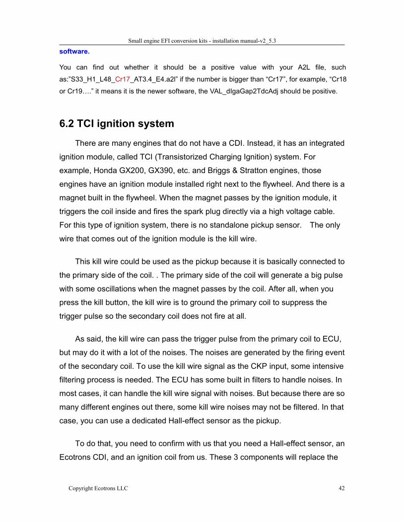
6.2.1 EFI Controls fuel onlyFor this type of ignition system, you can use the signal from kill switch wire as the
pick-up signal. Keep the stock ignition system, and the EFI just controls the fuel.
You need to connect the orange wire labeled as CKP from the EFI harness to the
kill wire and connect the EFI green wire which labeled as GND to the ground of
your ignition system.
1.1)If you have the below version harness, please connect it as below:
Note: The 2 small white connectors are for Ecotrons CDI. You don’t have toconnect them if you are not using Ecotrons CDI.
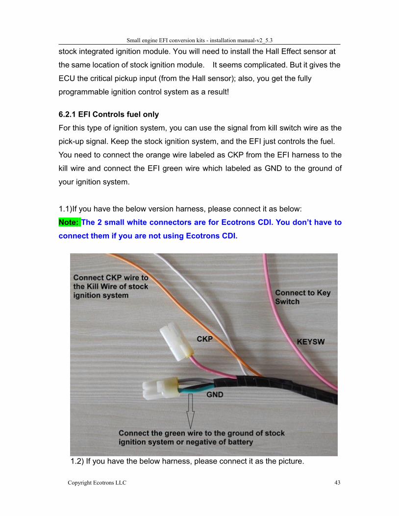
1.2) If you have the below harness, please connect it as the picture.
Small engine EFI conversion kits - installation manual-v2_5.3
Copyright Ecotrons LLC 44
6.2.2 EFI Controls both fuel and sparks with a Hall sensor
Because the kill switch wire from this type coil can have a lot of noise, it may not
work completely. You can convert this type ignition system to CDI ignition system.
To convert, you can use 3 of our components to replace this one integrated
ignition coil, namely: Hall-effect sensor, CDI, and a coil.
The Hall-effect sensor acts like a pickup; it shall be installed at the same location
as the stock ignition coil. A bracket may be needed. The CDI is controlled by our
ECU; and the coil is driven by the CDI, and fires the spark plug. It seems more
complicated, but the benefit is a fully controlled ignition system, you can program
the ignition maps as you want!
Small engine EFI conversion kits - installation manual-v2_5.3
Copyright Ecotrons LLC 45
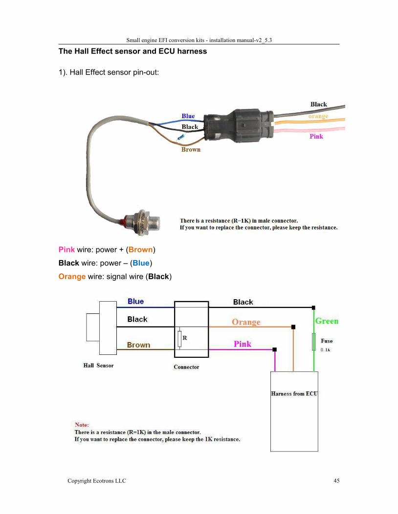
The Hall Effect sensor and ECU harness
1). Hall Effect sensor pin-out:
Pink wire: power + (Brown)Black wire: power – (Blue)Orange wire: signal wire (Black)
Small engine EFI conversion kits - installation manual-v2_5.3
Copyright Ecotrons LLC 46
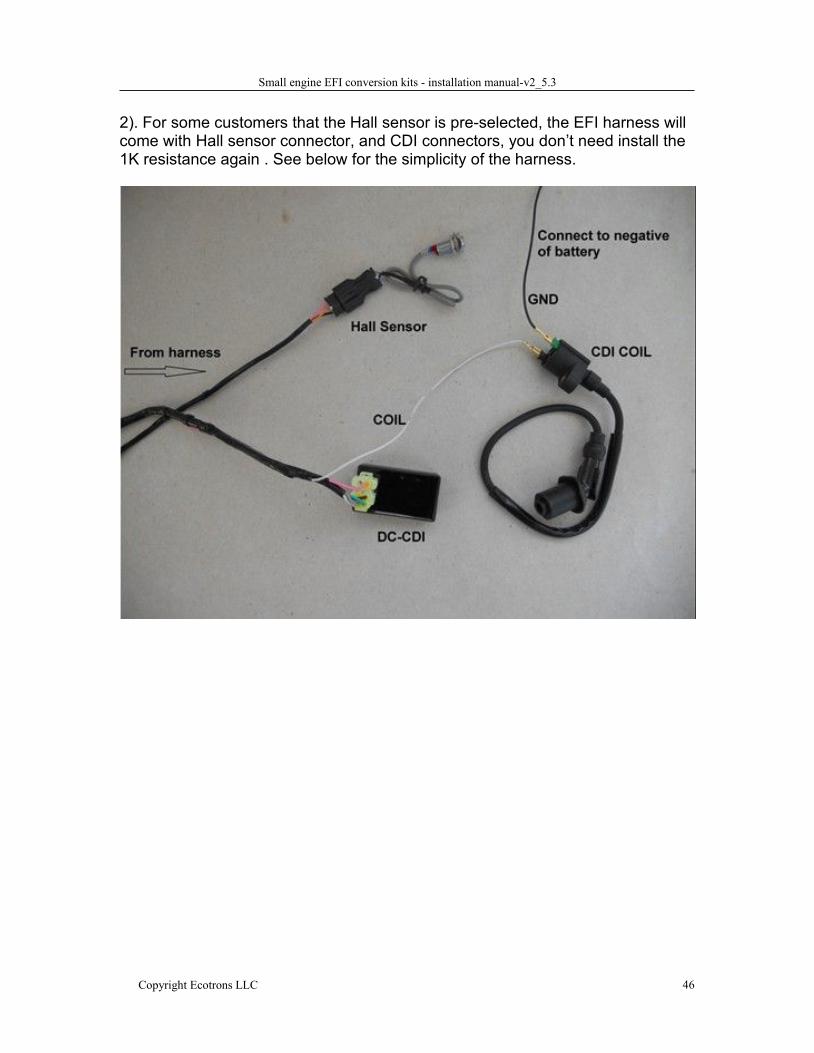
2). For some customers that the Hall sensor is pre-selected, the EFI harness willcome with Hall sensor connector, and CDI connectors, you don’t need install the1K resistance again . See below for the simplicity of the harness.
Small engine EFI conversion kits - installation manual-v2_5.3
Copyright Ecotrons LLC 47
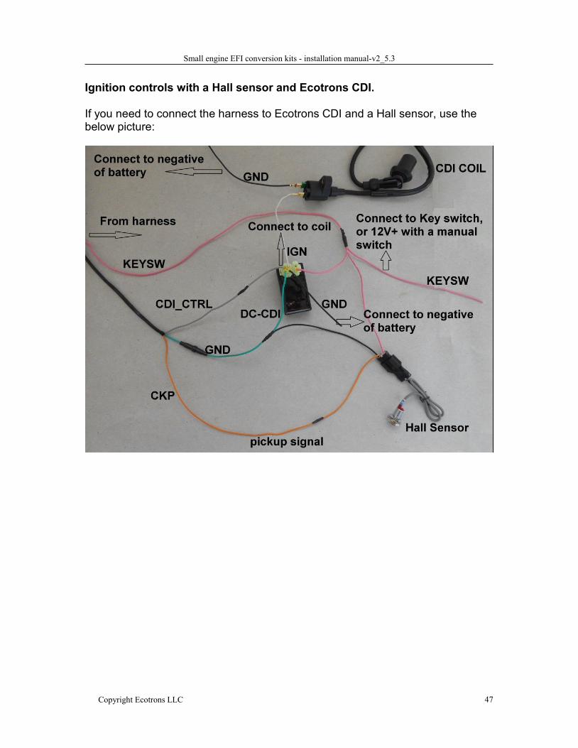
Ignition controls with a Hall sensor and Ecotrons CDI.
If you need to connect the harness to Ecotrons CDI and a Hall sensor, use thebelow picture:
Small engine EFI conversion kits - installation manual-v2_5.3
Copyright Ecotrons LLC 48
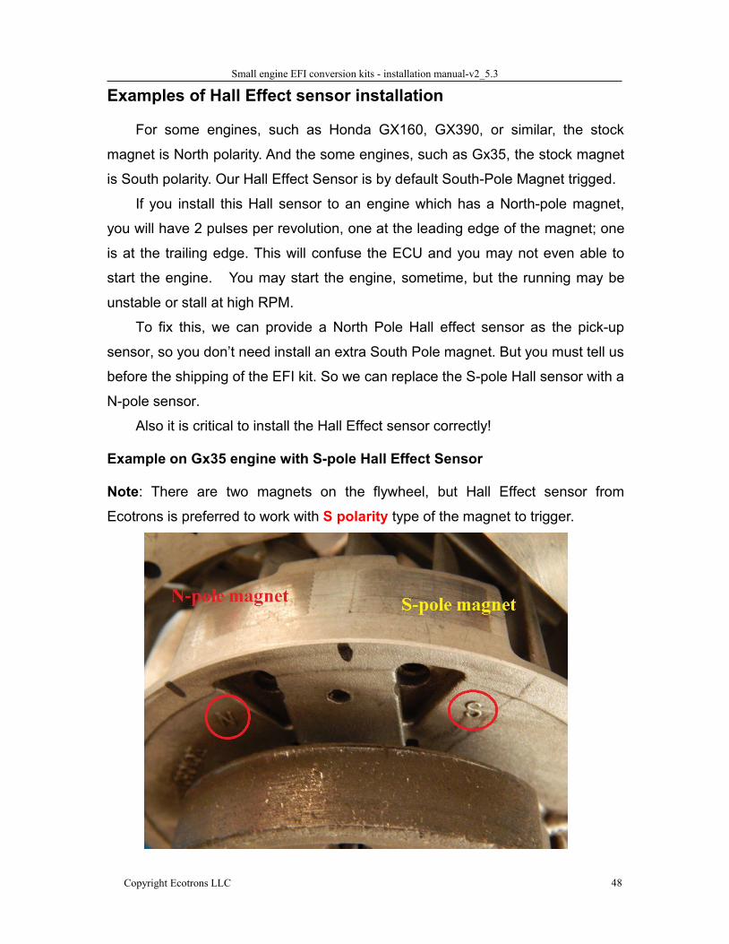
Examples of Hall Effect sensor installation
For some engines, such as Honda GX160, GX390, or similar, the stock
magnet is North polarity. And the some engines, such as Gx35, the stock magnet
is South polarity. Our Hall Effect Sensor is by default South-Pole Magnet trigged.
If you install this Hall sensor to an engine which has a North-pole magnet,
you will have 2 pulses per revolution, one at the leading edge of the magnet; one
is at the trailing edge. This will confuse the ECU and you may not even able to
start the engine. You may start the engine, sometime, but the running may be
unstable or stall at high RPM.
To fix this, we can provide a North Pole Hall effect sensor as the pick-up
sensor, so you don’t need install an extra South Pole magnet. But you must tell us
before the shipping of the EFI kit. So we can replace the S-pole Hall sensor with a
N-pole sensor.
Also it is critical to install the Hall Effect sensor correctly!
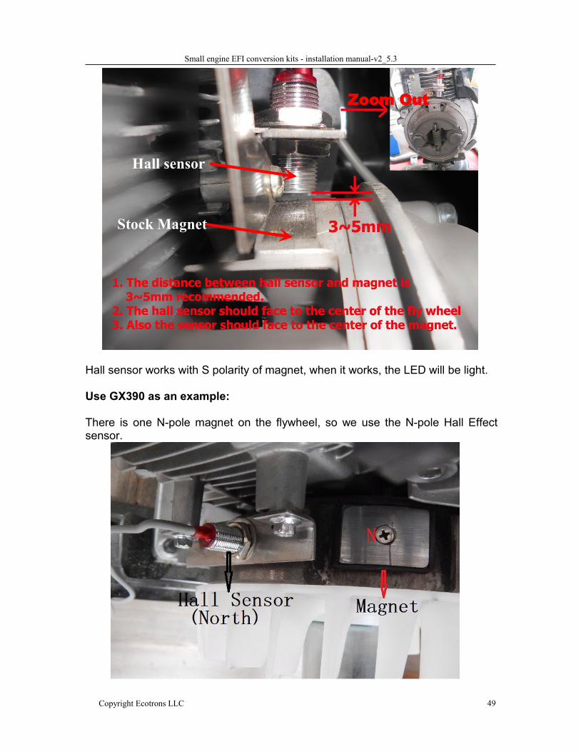
Example on Gx35 engine with S-pole Hall Effect Sensor
Note: There are two magnets on the flywheel, but Hall Effect sensor from
Ecotrons is preferred to work with S polarity type of the magnet to trigger.
Small engine EFI conversion kits - installation manual-v2_5.3
Copyright Ecotrons LLC 49
Hall sensor works with S polarity of magnet, when it works, the LED will be light.
Use GX390 as an example:
There is one N-pole magnet on the flywheel, so we use the N-pole Hall Effectsensor.
Stock Magnet
Hall sensor
Zoom Out
Small engine EFI conversion kits - installation manual-v2_5.3
Copyright Ecotrons LLC 50
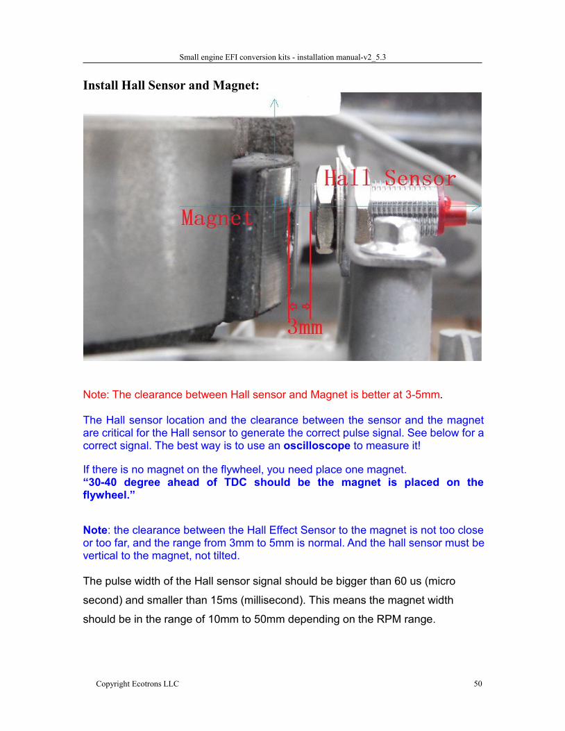
Install Hall Sensor and Magnet:
Note: The clearance between Hall sensor and Magnet is better at 3-5mm.
The Hall sensor location and the clearance between the sensor and the magnetare critical for the Hall sensor to generate the correct pulse signal. See below for acorrect signal. The best way is to use an oscilloscope to measure it!
If there is no magnet on the flywheel, you need place one magnet.“30-40 degree ahead of TDC should be the magnet is placed on theflywheel.”
Note: the clearance between the Hall Effect Sensor to the magnet is not too closeor too far, and the range from 3mm to 5mm is normal. And the hall sensor must bevertical to the magnet, not tilted.
The pulse width of the Hall sensor signal should be bigger than 60 us (micro
second) and smaller than 15ms (millisecond). This means the magnet width
should be in the range of 10mm to 50mm depending on the RPM range.
Small engine EFI conversion kits - installation manual-v2_5.3
Copyright Ecotrons LLC 51
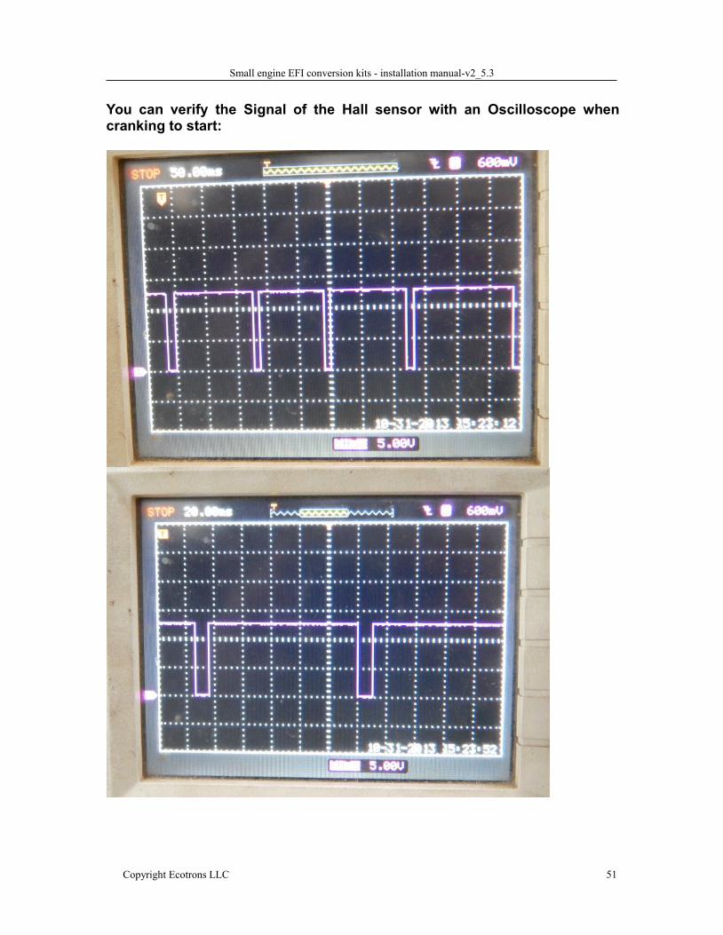
You can verify the Signal of the Hall sensor with an Oscilloscope whencranking to start:
Small engine EFI conversion kits - installation manual-v2_5.3
Copyright Ecotrons LLC 52
6.3 Mechanical break-point style ignition systemThere are still a lot of vintage bikes (vehicles) that are running on break-point
style ignition systems. In this case you may have to convert it to electrical
ignition system. You may want to convert it anyway, since it has already
created a lot of headache to you. There are 2 ways to convert this type of
ignition system:
Convert it to CDI system: good for single engines; you need to install a
magnet on the flywheel, or somewhere that synchronizes with the
crankshaft; and install our Hall effect sensor to be triggered by the
magnet; then our CDI and coil will be controlled by our ECU;
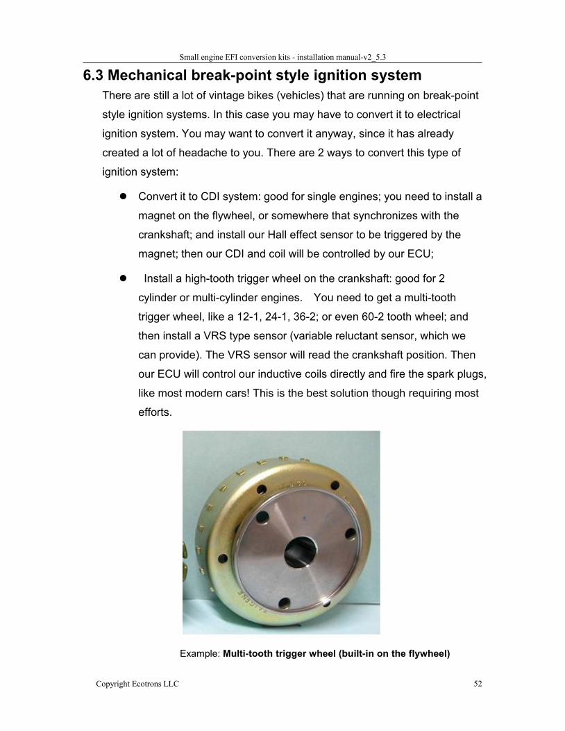
Install a high-tooth trigger wheel on the crankshaft: good for 2
cylinder or multi-cylinder engines. You need to get a multi-tooth
trigger wheel, like a 12-1, 24-1, 36-2; or even 60-2 tooth wheel; and
then install a VRS type sensor (variable reluctant sensor, which we
can provide). The VRS sensor will read the crankshaft position. Then
our ECU will control our inductive coils directly and fire the spark plugs,
like most modern cars! This is the best solution though requiring most
efforts.
Example: Multi-tooth trigger wheel (built-in on the flywheel)
Small engine EFI conversion kits - installation manual-v2_5.3
Copyright Ecotrons LLC 53
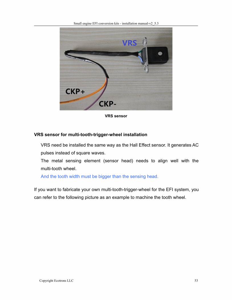
VRS sensor
VRS sensor for multi-tooth-trigger-wheel installation
VRS need be installed the same way as the Hall Effect sensor. It generates AC
pulses instead of square waves.
The metal sensing element (sensor head) needs to align well with the
multi-tooth wheel.
And the tooth width must be bigger than the sensing head.
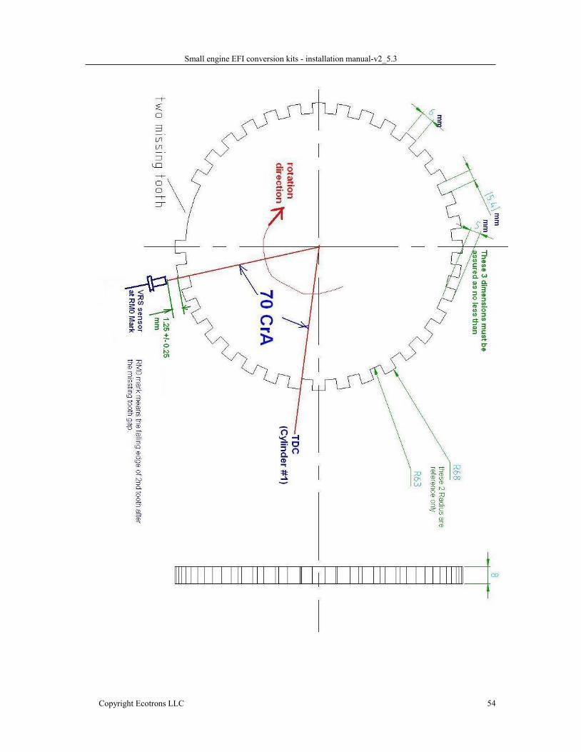
If you want to fabricate your own multi-tooth-trigger-wheel for the EFI system, you
can refer to the following picture as an example to machine the tooth wheel.
Small engine EFI conversion kits - installation manual-v2_5.3
Copyright Ecotrons LLC 54
Small engine EFI conversion kits - installation manual-v2_5.3
Copyright Ecotrons LLC 55
Why the EFI doesn’t work after the Hall Effect Sensor installed?
Q: After installing the Hall sensor, and if I rotate the crankshaft, the LED ison and off when the magnet passes through the Hall sensor. But EFI doesnot do anything.
A: Step 1: If you ordered the EFI without the Hall sensor but added the Hall
sensor later, likely you do not have the right ECU software. Please check the A2l
and CAL file and make sure it is suitable for the Hall Sensor. Or contact us and
send back the A2l and CAL file, we will help you to check it.
Step 2: Check whether the Hall sensor polarity is same as the magnet polarity.
If the sensor LED only turns on at the edge of the magnet, but turns off in
the center of the magnet, this means they have opposite polarity. You
need contact us to get a different polarity Hall sensor, like a N-pole
sensor.
Step 3: Double check the wire connection if it is yourself who connected the
individual wires. The power wire of Hall sensor, and the signal wire to
CKP (Orange) wire; the ground wire to harness ground or 12v negative.
You can take some photos and send to us for confirmations.
If you ordered the EFI with the Hall sensor and the harness comes with
the Hall sensor connector, then you don’t need to worry this step.
Step 3: The ultimate check: use an oscilloscope to measure the signal from the
CKP wire. Most people don’t have a scope; some may have it in the lab. It is a
bullet proof way for those who have a scope.
When the Hall sensor is aligned with the magnet, the LED is on, the voltage
should be 0V (low voltage); and when the Hall sensor is not aligned with the
magnet, the LED is off, the voltage of the signal should be 12V (high voltage).
Q: After installing the Hall sensor, ECU can read the RPM signal, but it is noteasy to start or it is not running stable
A: Likely the installation of Hall sensor is not perfect. The sensor may be
mis-aligned with the magnet, or skewed against the flywheel. Please double
Small engine EFI conversion kits - installation manual-v2_5.3
Copyright Ecotrons LLC 56
check the alignment, and please read closely the previous section, and pictures
there; and adjust the Hall sensor position precisely.
Note: The clearance between Hall sensor and Magnet is better at 3-5mmHall sensor is installed as vertical to magnet.
Also the sensor should face to the center of the magnet.
Both length and width of the magnet must be 12mm at least.
Q: I use the stock magnet, but there are two magnets on the flywheel, theengine can’t start
A: The 2 magnets may have different polarity. One is N-pole, one is S-pole.
Check which magnet turns the Hall sensor LED on. If the LED turns on more
than once in a full revolution, then ECU gets confused,
In this case, you need to identify what is the polarity of the leading magnet, and
get a Hall sensor for that magnet,
If the LED only turns on only once, and it turns on during full magnet length, not
just at the edges of the magnet, the sensor is matching, and you may need the
correct software (CAL file).
So, please use the corresponding Hall sensor to match the stock magnet, for
example, the stock magnet is N-pole, you need use a N-pole Hall sensor; the
stock magnet is S-pole, you need use a S-pole Hall sensor.
Another way, you can get rid of the stock magnets, or not to use the stock
magnets, and use the magnet comes with the EFI kit (if you ordered the Hall
sensor with the EFI, there is one magnet included).
Q: I didn’t order a Hall sensor, but I installed a Hall sensor later
A: please install the Hall sensor in the correct method, and contact us for the
correct software for the Hall sensor system. Our generic EFI kit comes by default
to work with a VRS type of sensor, Variable Reluctant Sensor. It generates a
positive pulse to ECU. It is High assertive.
Small engine EFI conversion kits - installation manual-v2_5.3
Copyright Ecotrons LLC 57
The Hall Effect sensor generates a reversed polarity pulse, and it is low assertive.
So in this case, you need a new CAL file from us (software file).
You may be able to change the CAL if you can find it: VAL_CKP_Pulse_Polarity
= 0 or 1.
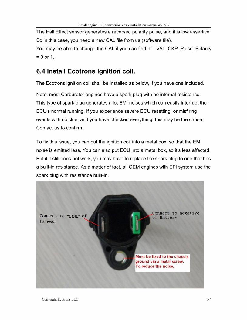
6.4 Install Ecotrons ignition coil.
The Ecotrons ignition coil shall be installed as below, if you have one included.
Note: most Carburetor engines have a spark plug with no internal resistance.
This type of spark plug generates a lot EMI noises which can easily interrupt the
ECU's normal running. If you experience severe ECU resetting, or misfiring
events with no clue; and you have checked everything, this may be the cause.
Contact us to confirm.
To fix this issue, you can put the ignition coil into a metal box, so that the EMI
noise is emitted less. You can also put ECU into a metal box, so it's less affected.
But if it still does not work, you may have to replace the spark plug to one that has
a built-in resistance. As a matter of fact, all OEM engines with EFI system use the
spark plug with resistance built-in.
Small engine EFI conversion kits - installation manual-v2_5.3
Copyright Ecotrons LLC 58
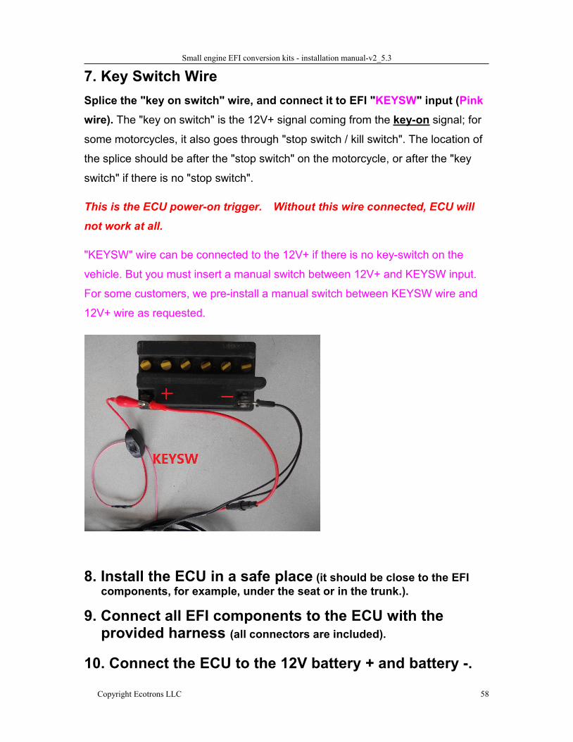
7. Key Switch WireSplice the "key on switch" wire, and connect it to EFI "KEYSW" input (Pinkwire). The "key on switch" is the 12V+ signal coming from the key-on signal; for
some motorcycles, it also goes through "stop switch / kill switch". The location of
the splice should be after the "stop switch" on the motorcycle, or after the "key
switch" if there is no "stop switch".
This is the ECU power-on trigger. Without this wire connected, ECU will
not work at all.
"KEYSW" wire can be connected to the 12V+ if there is no key-switch on the
vehicle. But you must insert a manual switch between 12V+ and KEYSW input.
For some customers, we pre-install a manual switch between KEYSW wire and
12V+ wire as requested.
8. Install the ECU in a safe place (it should be close to the EFIcomponents, for example, under the seat or in the trunk.).
9. Connect all EFI components to the ECU with theprovided harness (all connectors are included).
10. Connect the ECU to the 12V battery + and battery -.
Small engine EFI conversion kits - installation manual-v2_5.3
Copyright Ecotrons LLC 59
11. Make sure your 12V battery- is connected to thechassis ground!
If your engine or vehicle did not have a 12V battery before, and you just
added one,
you must connect the 12V - to chassis ground.
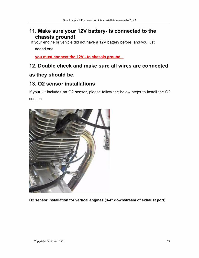
12. Double check and make sure all wires are connectedas they should be.13. O2 sensor installationsIf your kit includes an O2 sensor, please follow the below steps to install the O2
sensor:
O2 sensor installation for vertical engines (3-4" downstream of exhaust port)
Small engine EFI conversion kits - installation manual-v2_5.3
Copyright Ecotrons LLC 60
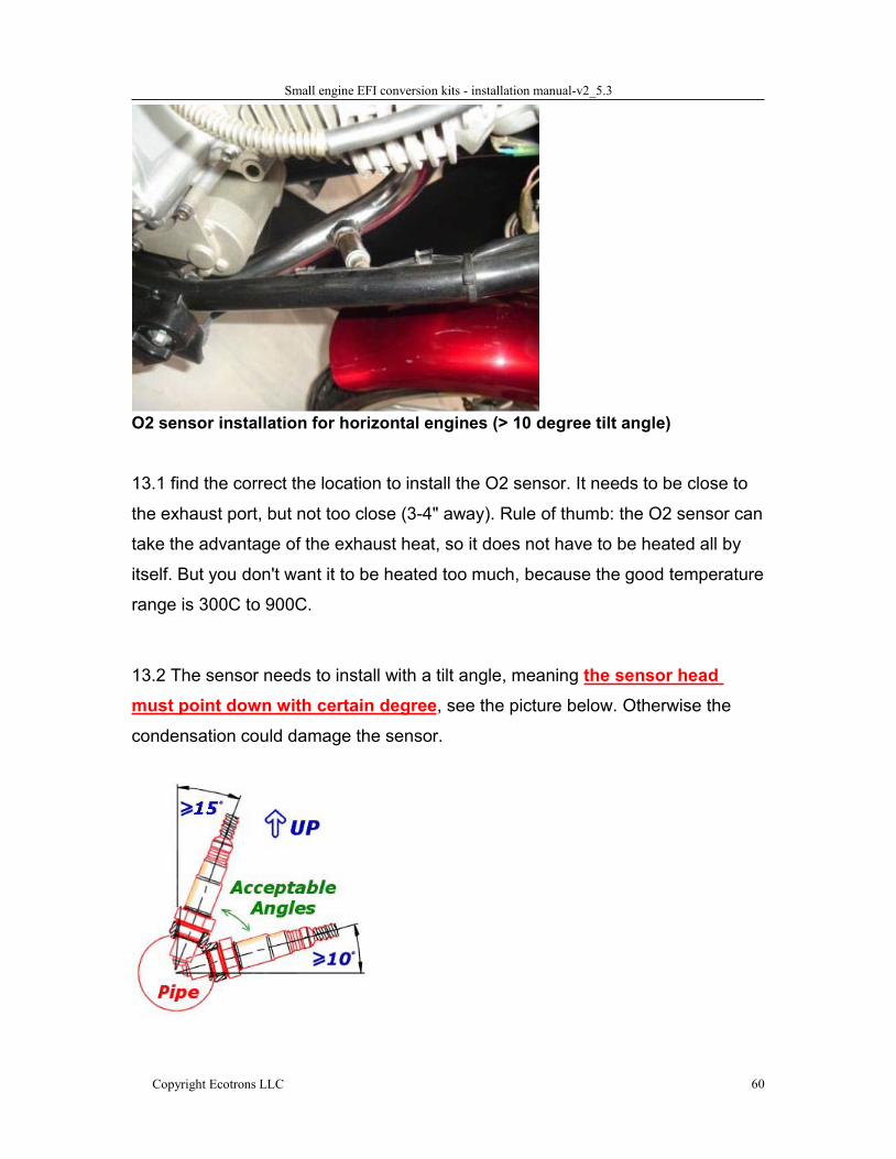
O2 sensor installation for horizontal engines (> 10 degree tilt angle)
13.1 find the correct the location to install the O2 sensor. It needs to be close to
the exhaust port, but not too close (3-4" away). Rule of thumb: the O2 sensor can
take the advantage of the exhaust heat, so it does not have to be heated all by
itself. But you don't want it to be heated too much, because the good temperature
range is 300C to 900C.
13.2 The sensor needs to install with a tilt angle, meaning the sensor headmust point down with certain degree, see the picture below. Otherwise the
condensation could damage the sensor.

Small engine EFI conversion kits - installation manual-v2_5.3
Copyright Ecotrons LLC 61
13.3 drill a hole on the exhaust pipe. Weld the O2 sensor bung (provided) on
the hole. Make sure the sensor head can be fully exposed to the exhaust gas;
yet NOT to block the exhaust pipe.
13.4 install the sensor in the bung. Connect the O2 sensor cable.
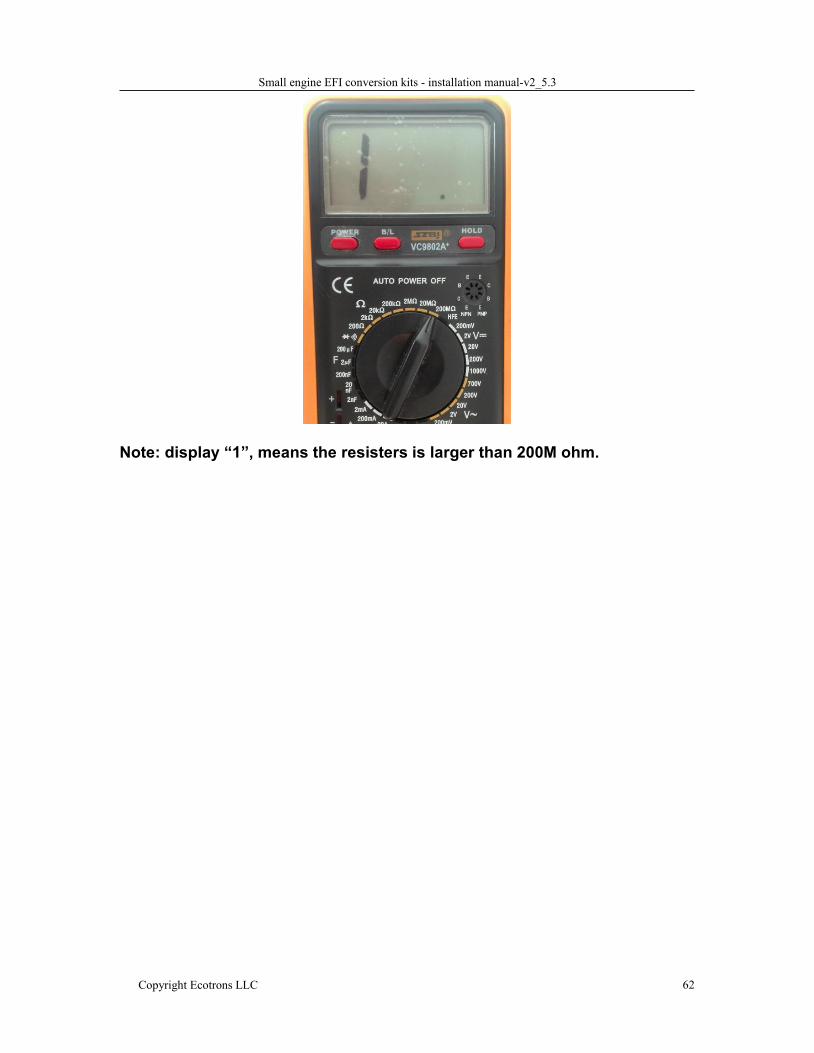
How to check NB O2 sensor damaged?
When you finished installing the NB O2 sensor and the engine runs about 20
minutes, the signal of NB O2 sensor (uLsb) is not changed, and the closed-loop
control doesn’t work, maybe there is something with the NB O2 sensor, so you
need check it by using a multi-meter, and measure the resistance between the
two heat wires.
1) Select the 200ohm, to test the resistance between the two white wires. If
the resistance is not range from 8 to 11, it means there is something wrong
with the NB O2 sensor.
2) Select the 200M ohm, to test any two wires except the two white wires, if
the resistance is less than 200M ohm, it means there is something wrong
with the NB O2 sensor.
Small engine EFI conversion kits - installation manual-v2_5.3
Copyright Ecotrons LLC 62
Note: display “1”, means the resisters is larger than 200M ohm.
Small engine EFI conversion kits - installation manual-v2_5.3
Copyright Ecotrons LLC 63
Initial test after the installation1. Before you do the initial test of the EFI kit, make sure the installation is done as
the previous section.
2. Key-on and KEY-ON ONLY!3. You should hear fuel pump noise running for a few seconds, if this is not
happening, you must have some wiring problem. Re-check all your wires! If
every wire is sure correctly connected, then the ECU may have a problem.
4. If you hear the fuel pump running and then stop, this indicates the ECU is
working. Now you can fill the fuel tank with the regular gasoline.
5. Repeat the above step 3 times, to make sure the fuel supply lines are filled up
with fuel. No air pocket! No bubbles!
6. Sometime, you have to manually purge out all the air bubbles in the fuel supply
system, because it is possible that if the fuel pump itself has a lot bubbles in
there, it could not pump fuel at all, it is only spinning like idle without load. In
this case the noise of fuel pump is little higher pitch than with fuel pumping. In
this case you will not be able to start no matter what, because no fuel pumping.
If you have any doubt that the fuel supply system has some air pocket or air
bubbles, you can un-plug the high pressure fuel line, pointing it into a bottle,
and key-on, you should see fuel sprout out if fuel pump is working and no air
bubbles.
7. In many cases, you can visually see the fuel flow out of the fuel pressure
regulator and return back to the tank if the fuel supply system is working
normally. This is another indication you can check.
8. After you make sure the fuel supply system is working normally, try to key-start
the engine.
9. First time you start the engine, there may be still some air bubbles in the fuel
supply system needs to be purged. So don’t be surprised that the first start
takes longer, or even you need to start multiple times to be successful.
10. If the engine does not start, go to the next section for diagnosis.
11.After the engine starts, if it’s rough idling; let it warm up, and let the ECU
Small engine EFI conversion kits - installation manual-v2_5.3
Copyright Ecotrons LLC 64
self-adapting to the engine for a while.
12. After the idle stabilizes, drive the vehicle in a steady state ( constant
throttles or constant speeds) at different throttle/speeds. Let the ECU
self-adapting further.
13. Then you can try different transient conditions, like fast opening of the
throttle, etc.
My engine does not start, why?1) Have you followed the installation manual completely?
1.1) Can you tell that the ECU is controlling the fuel pump?
1.1.1) when you turn on the key, do you hear the fuel pump running
for a few seconds, and then stop? If not, you have wiring
issues.
1.1.2) Key-off for 3s, and key-on, do you hear the fuel pump running
for a few seconds, and then stop? If not, you have wiring
issues.
1.1.3) Every time when you try to start the engine (engine spins), do
you hear the fuel pump running until engine stalls? If not, your
wiring has issues.
1.2) Do you have the fuel pump installed correctly?
1.2.1) is the fuel pump lower than the tank? The fuel pump must be
lower than the tank to avoid fuel starvation. The fuel pump can
be higher than the injector, if limited by the space.
1.2.2) Have you replaced the "petcock" tank valve with a manual
valve? EFI does not work with the petcock that does not have
a PRIME position.
1.2.3) Do you have a fuel return line back to the fuel tank? Our EFI
kit currently needs a way to return the fuel to the tank.
1.2.4) Is there impurity in the gasoline? Check your fuel filter.
Small engine EFI conversion kits - installation manual-v2_5.3
Copyright Ecotrons LLC 65
1.3) Do you have the ignition pick up sensor connected correctly?
1.3.1) Do you have a correct pick up signal input to ECU (CKP wire
on the harness)?
1.3.2) Do you have the ground wire of pickup sensor connected to
ECU ground wire (GREEN wire on the harness)?
1.3.3) Are you using the stock ignition system (to isolate the starting
problem, please use the stock ignition system)?
1.3.4) Can you tell the spark plug is firing whey you try to start?
1.4) Do you have the MAP sensor installed correctly?
1.4.1) Is the MAP sensor connected to the throttle body tube via the
small hose (included in the kit)?
1.4.2) is the intake air system air tight (no other way for free air going
into the cylinder except through the throttle)?
2) Do you have the MIL Lamp on (if your harness comes with a MIL Lamp
installed)? If yes, go to “ProCAL installation”.
3) Install the ProCAL (coming in the CD, or downloadable at our website):
3.1) ProCAL does not support Windows Vista at this moment. Please use
Windows XP (the most tested environment), or Win7, Win8.
3.2) you installed the ProCAL into your computer, but it does not talk to the ECU:
please check your USB adaptor is fully plugged in. And ProCAL communication
setting is set as USB.
Or better: use an old computer which has a built-in COM port to rule out the
USB converter problem.
3.3) establish the communication between the ProCAL and the ECU: menu
run connect; then menu run start measuring; you should see the
gauges starting to show values.
Small engine EFI conversion kits - installation manual-v2_5.3
Copyright Ecotrons LLC 66
3.4) Read diagnostic trouble codes by goto: menu diagnosis run
diagnosis read DTC.
4) With the ProCAL communicating with ECU, do the below tests:
4.1) Try to start the engine (with the engine spinning), Read the variables in
ProCAL:
4.2) Does the signal "RPM" changing from 0 to some value > 300rpm?
4.3) Does the "Map" signal drops from about 1013hPa to below 600hPa? If
either of the above 2 is NO, you could have some wiring problem. If both the
above are YES, you could have fuel supply issue: air bubbles in the fuel lines,
or fuel clogged somewhere.
5) To rule out the problem of the ignition pickup sensor, do the below tests:
5.1) disconnect both CKP wire and GND wire from the ignition pickup sensor
and tape them;
5.2) make sure the stock ignition system is untouched;
5.3) Try to start the engine, and check the below:
5.4) Does the signal "RPM" changing from 0 to some value > 300rpm?
5.5) Does the "Map" signal drops from about 1013hPa to below 600hPa? If
either of the above 2 is NO, you could have some wiring problem. If both the
above are YES, you could have fuel supply issue: air bubbles in the fuel lines,
or fuel clogged somewhere.
With all the above questions and tests done, you still cannot figure out why the
engine does NOT start, please contact us directly:
Small engine EFI conversion kits - installation manual-v2_5.3
Copyright Ecotrons LLC 67
How to install the provided ProCAL softwareto your computer?For details on how to use ProCAL software, please refer to the ProCAL Manual,
downloadable here:
www.ecotrons.com/support
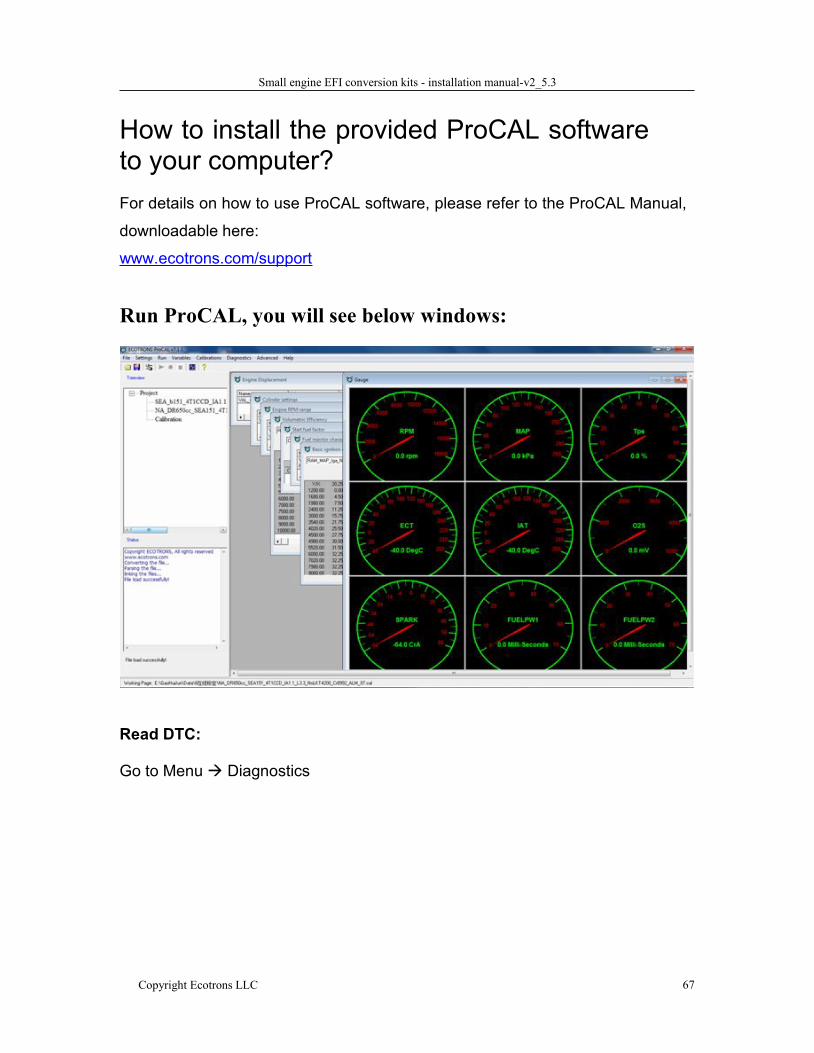
Run ProCAL, you will see below windows:
Read DTC:
Go to Menu Diagnostics
Small engine EFI conversion kits - installation manual-v2_5.3
Copyright Ecotrons LLC 68
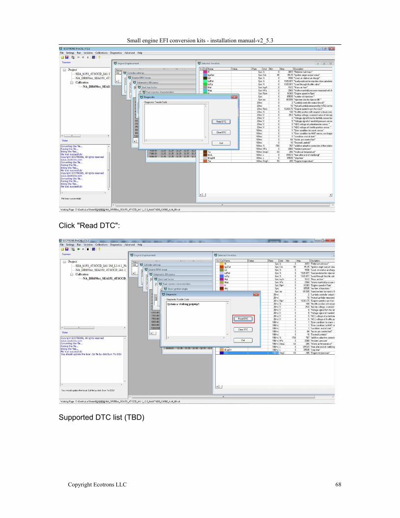
Click "Read DTC":
Supported DTC list (TBD)
Small engine EFI conversion kits - installation manual-v2_5.3
Copyright Ecotrons LLC 69
Diagnosis of the communications betweenyour laptop and ECU:
1.1 Check your serial communication cable; make sure the cable is plugged incompletely.
1.2 Check your USB adaptor; make sure it is fully plugged into your laptop.1.3 If your laptop has a built-in COM port (many old laptops have that); you
can use the COM port directly without the USB adaptor.1.4 Go to "Menu setting communications" select correct port: USB orCOM port.1.5 Click "Connect" button in ProCAL.
How to check a non-working ECU
How to tell the ECU is damaged?
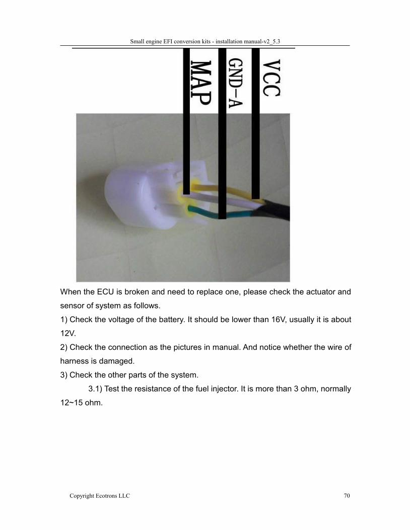
1) Key off, and disconnect 12V+ of ECU harness;
2) Disconnect the MAP sensor;
3) Use a multi-meter, Measure the resistance between the 2 wires on the
connector of harness side, as in the below picture:
What is resistance between the 2 wires of “VCC” and “GND-A”?
If it is smaller than 100 ohm that means the ECU is damaged somehow. The
normal value should be about 1K ohm.
If ECU is damaged, most likely some ground wire is accidentally shorted to the
12V+; or VCC is shorted to ground wire. For example, the GND-A is connected to
12V+; or VCC.
Small engine EFI conversion kits - installation manual-v2_5.3
Copyright Ecotrons LLC 70
When the ECU is broken and need to replace one, please check the actuator and
sensor of system as follows.
1) Check the voltage of the battery. It should be lower than 16V, usually it is about
12V.
2) Check the connection as the pictures in manual. And notice whether the wire of
harness is damaged.
3) Check the other parts of the system.
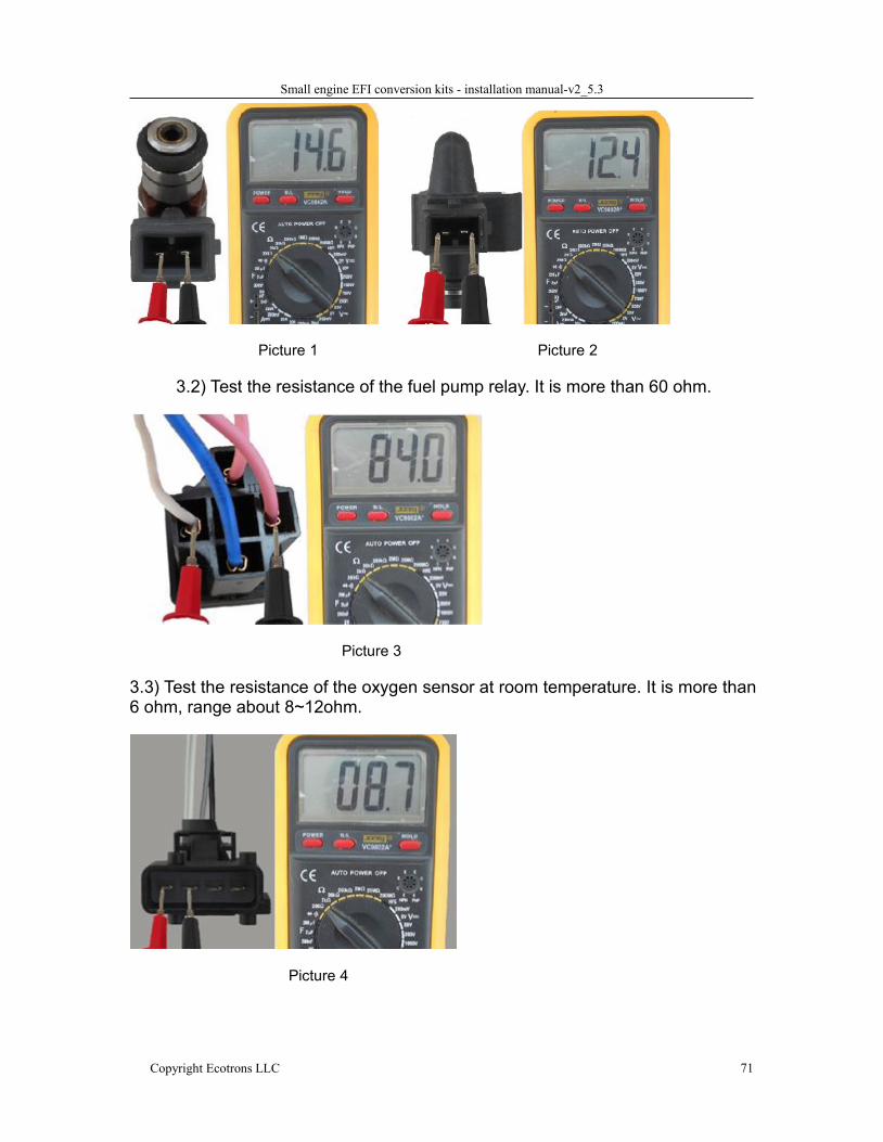
3.1) Test the resistance of the fuel injector. It is more than 3 ohm, normally
12~15 ohm.
Small engine EFI conversion kits - installation manual-v2_5.3
Copyright Ecotrons LLC 71
Picture 1 Picture 2
3.2) Test the resistance of the fuel pump relay. It is more than 60 ohm.
Picture 3
3.3) Test the resistance of the oxygen sensor at room temperature. It is more than6 ohm, range about 8~12ohm.
Picture 4
Small engine EFI conversion kits - installation manual-v2_5.3
Copyright Ecotrons LLC 72
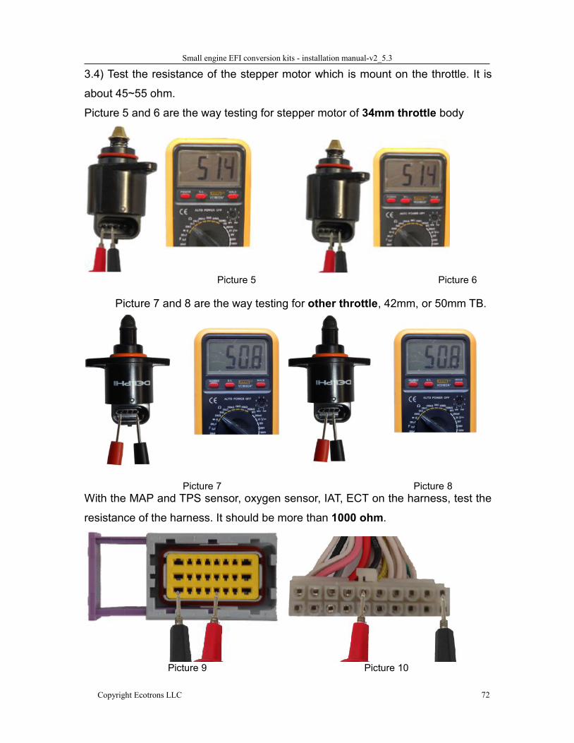
3.4) Test the resistance of the stepper motor which is mount on the throttle. It is
about 45~55 ohm.
Picture 5 and 6 are the way testing for stepper motor of 34mm throttle body
Picture 5 Picture 6
Picture 7 and 8 are the way testing for other throttle, 42mm, or 50mm TB.
Picture 7 Picture 8With the MAP and TPS sensor, oxygen sensor, IAT, ECT on the harness, test the
resistance of the harness. It should be more than 1000 ohm.
Picture 9 Picture 10
Small engine EFI conversion kits - installation manual-v2_5.3
Copyright Ecotrons LLC 73
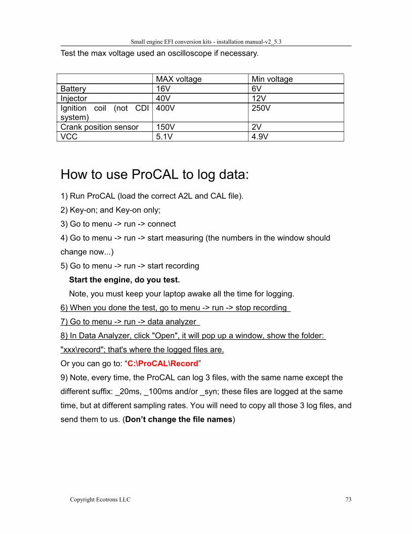
Test the max voltage used an oscilloscope if necessary.
MAX voltage Min voltageBattery 16V 6VInjector 40V 12VIgnition coil (not CDIsystem)
400V 250V
Crank position sensor 150V 2VVCC 5.1V 4.9V
How to use ProCAL to log data:1) Run ProCAL (load the correct A2L and CAL file).
2) Key-on; and Key-on only;
3) Go to menu -> run -> connect
4) Go to menu -> run -> start measuring (the numbers in the window should
change now...)
5) Go to menu -> run -> start recording
Start the engine, do you test.Note, you must keep your laptop awake all the time for logging.
6) When you done the test, go to menu -> run -> stop recording
7) Go to menu -> run -> data analyzer
8) In Data Analyzer, click "Open", it will pop up a window, show the folder:
"xxx\record"; that's where the logged files are.
Or you can go to: “C:\ProCAL\Record”9) Note, every time, the ProCAL can log 3 files, with the same name except the
different suffix: _20ms, _100ms and/or _syn; these files are logged at the same
time, but at different sampling rates. You will need to copy all those 3 log files, and
send them to us. (Don’t change the file names)

Small engine EFI conversion kits - installation manual-v2_5.3
Copyright Ecotrons LLC 74
How does the performance switch work?"Performance Switch" has 2 positions: ECO vs RICH. In ECO position, the EFI will
run the base fuel "map", or stoic metric AFR, which gives the best fuel economy,
and least emissions. In RICH mode, the EFI will run the enriched "map", or rich
AFR (at high load, high RPM, esp. at WOT), which gives more power.
"Performance Switch" is meant to let the user's easily switch between the
economy and enrichment modes in real-time, so that one can run for economy
when cruising around the town; and can immediately switch to performance mode
as he wants.
OFF -> ECO -> STOIC
ON -> RICH -> POWER
Small engine EFI conversion kits - installation manual-v2_5.3
Copyright Ecotrons LLC 75
How to connect ALM-S to ECU for Auto Tuning?Auto-Tuning:
Auto-Tuning means ALM and ECU will work together and tune the AFR as
you want. In ECU, AFR is represented by Lambda (equivalent AFR). Lambda = 1
means AFR 14.7 for gasoline.
The default target Lambda is 1.0 across the board. You can define your own
desired Lambda dependent on the RPM and TPS. Usually, a little rich AFR at high
RPM / high TPS is preferred to have a better performance as well as engine
cooling effect. A typical desired Lambda table could be 0.85 at high RPM and high
TPS (>90%); and 1.0 everywhere else. The desired Lambda table should be
engine specific. Some engines don't like 14.7 AFR at idle, and can only be stable
if it is a little rich. In that case, you shall define the desired Lambda to match the
engine characteristics.
With the Auto-Tuning feature, ECU will read the ALM's real-time lambda
input, and automatically adjust the fuel towards the desired Lambda at that RPM
and TPS status. ECU will store the learnt data in its own memory. After you run
the engine at different operating conditions (RPM vs TPS) for a while; it will
eventually learn most of operating points. And the engine is tuned then.
All you need to do is to drive your vehicle in different throttle positions,
preferred steady state driving. ECU-ALM will take care of the rest.
Connect ALM-S to ECU.
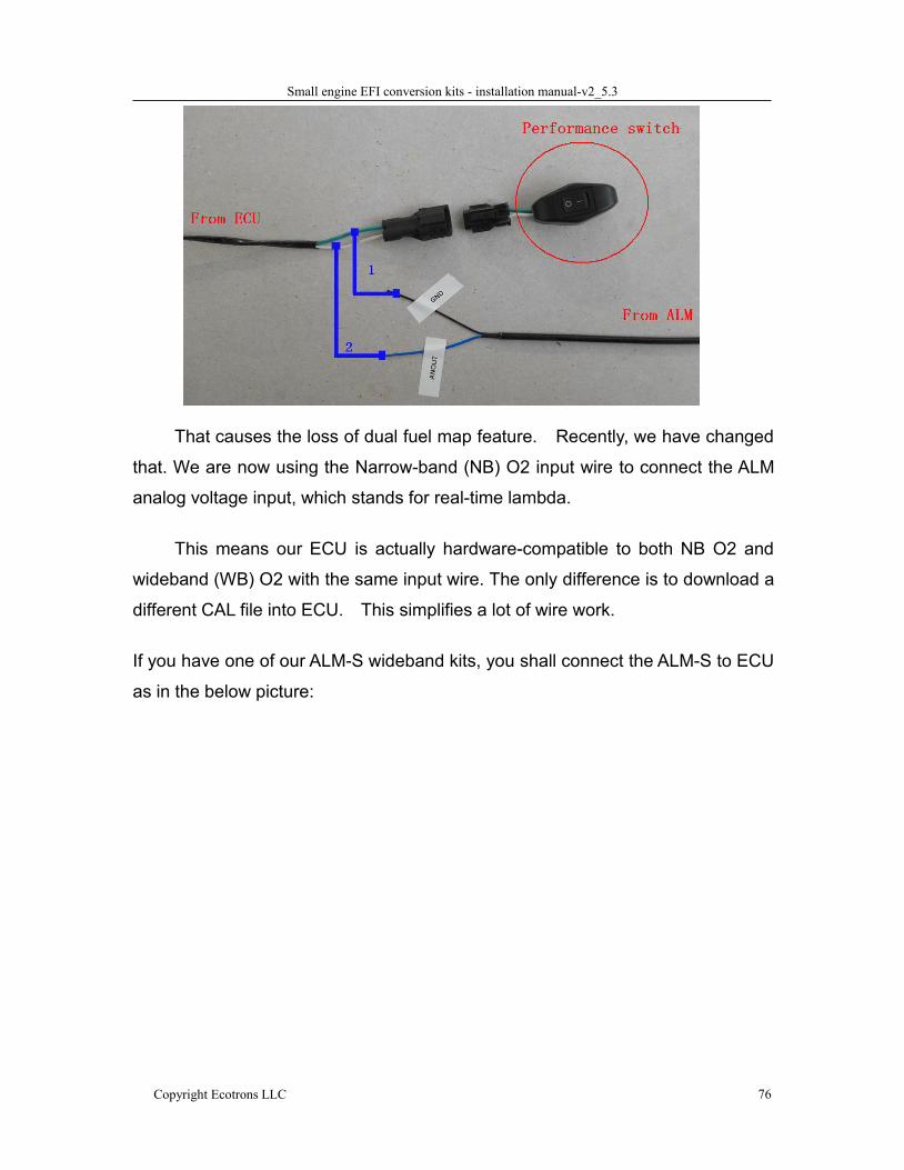
Previously we used the "Perf-SW", performance switch, wire to connect the
ALM input.
Small engine EFI conversion kits - installation manual-v2_5.3
Copyright Ecotrons LLC 76
That causes the loss of dual fuel map feature. Recently, we have changed
that. We are now using the Narrow-band (NB) O2 input wire to connect the ALM
analog voltage input, which stands for real-time lambda.
This means our ECU is actually hardware-compatible to both NB O2 and
wideband (WB) O2 with the same input wire. The only difference is to download a
different CAL file into ECU. This simplifies a lot of wire work.
If you have one of our ALM-S wideband kits, you shall connect the ALM-S to ECU
as in the below picture:
Small engine EFI conversion kits - installation manual-v2_5.3
Copyright Ecotrons LLC 77
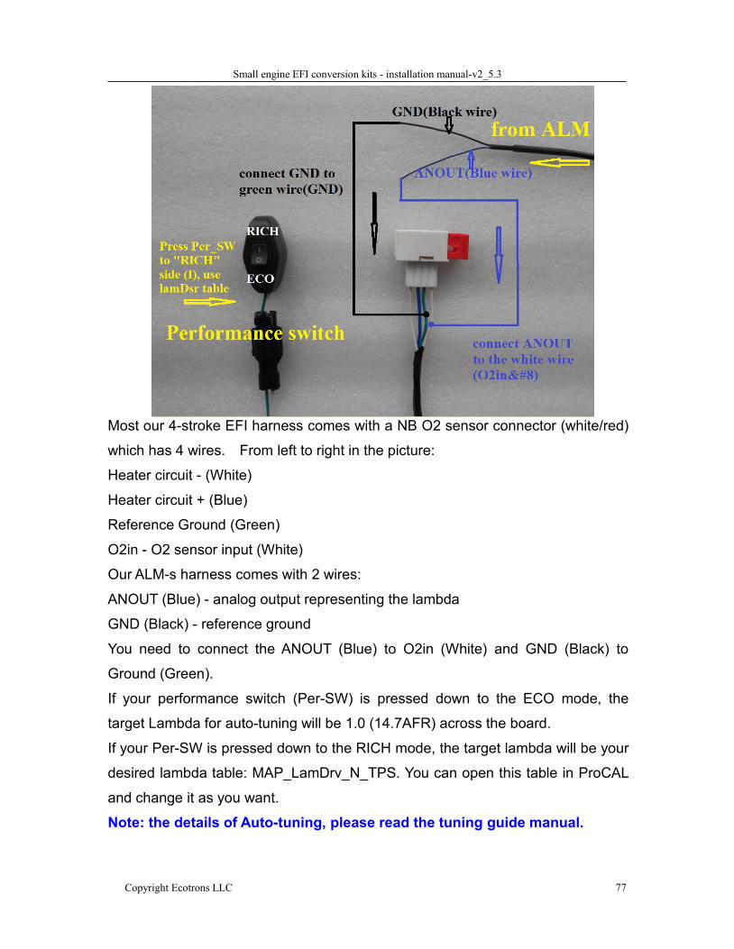
Most our 4-stroke EFI harness comes with a NB O2 sensor connector (white/red)
which has 4 wires. From left to right in the picture:
Heater circuit - (White)
Heater circuit + (Blue)
Reference Ground (Green)
O2in - O2 sensor input (White)
Our ALM-s harness comes with 2 wires:
ANOUT (Blue) - analog output representing the lambda
GND (Black) - reference ground
You need to connect the ANOUT (Blue) to O2in (White) and GND (Black) to
Ground (Green).
If your performance switch (Per-SW) is pressed down to the ECO mode, the
target Lambda for auto-tuning will be 1.0 (14.7AFR) across the board.
If your Per-SW is pressed down to the RICH mode, the target lambda will be your
desired lambda table: MAP_LamDrv_N_TPS. You can open this table in ProCAL
and change it as you want.
Note: the details of Auto-tuning, please read the tuning guide manual.

Small engine EFI conversion kits - installation manual-v2_5.3
Copyright Ecotrons LLC 78
Appendix I: fuel supply systems,
Appendix II: Wiring harness diagram
Appendix III: ECU pin-out
Small engine EFI conversion kits - installation manual-v2_5.3
Copyright Ecotrons LLC 79
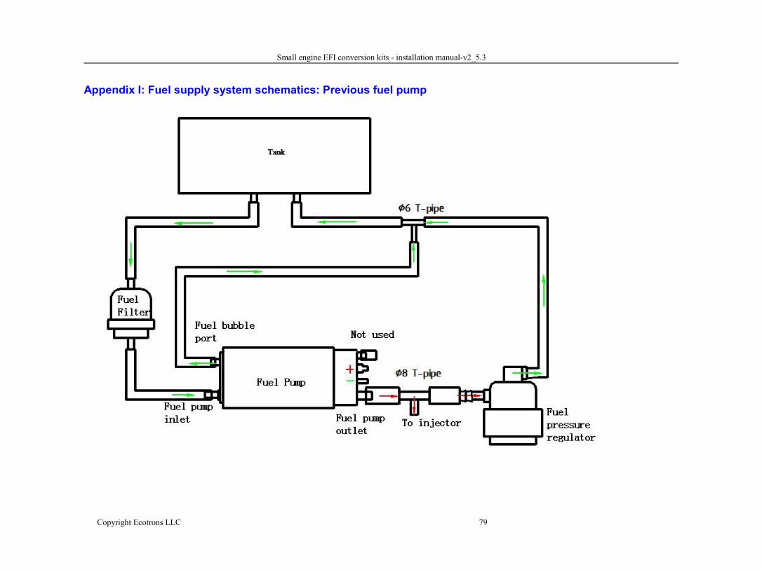
Appendix I: Fuel supply system schematics: Previous fuel pump
Small engine EFI conversion kits - installation manual-v2_5.3
Copyright Ecotrons LLC 80
Newest Small Fuel pump
Small engine EFI conversion kits - installation manual-v2_5.3
Copyright Ecotrons LLC 81
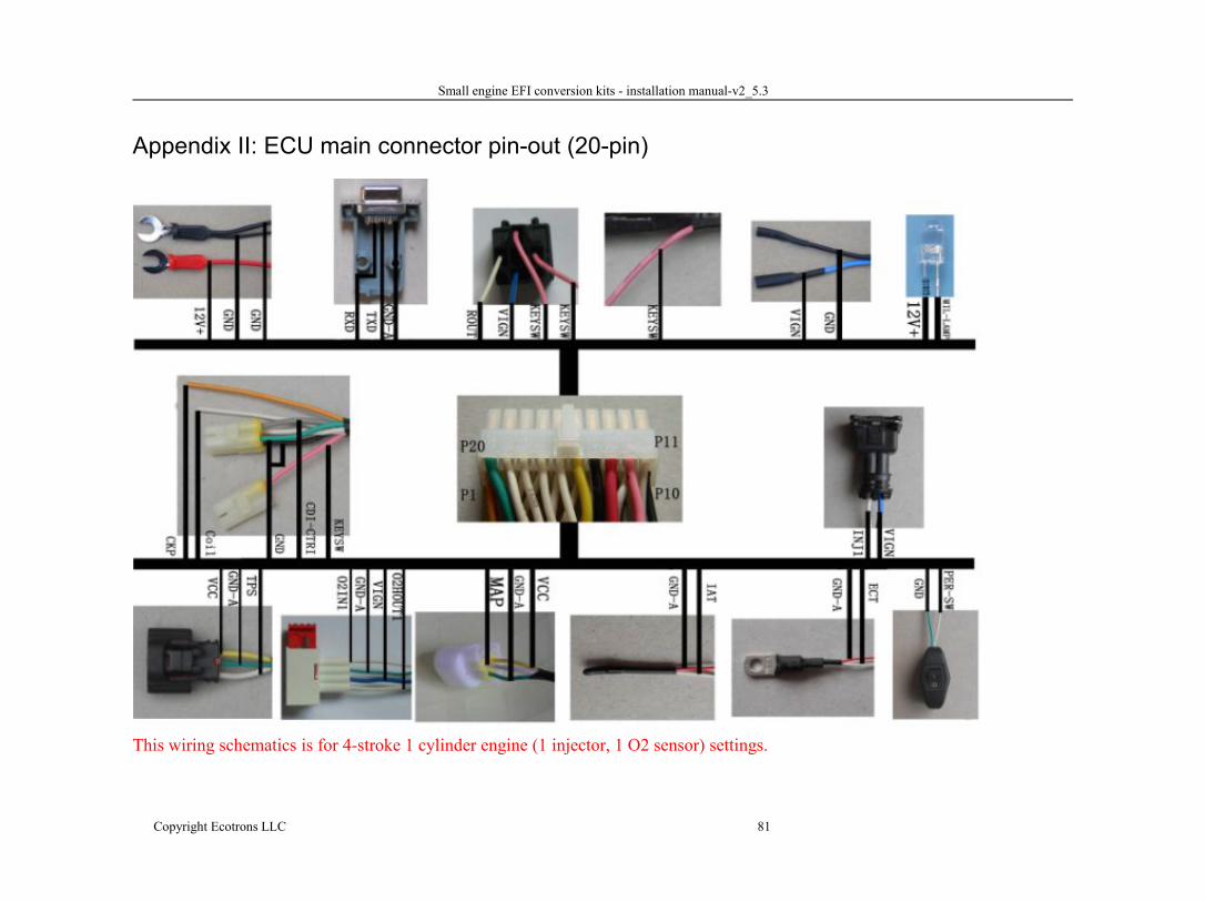
Appendix II: ECU main connector pin-out (20-pin)
This wiring schematics is for 4-stroke 1 cylinder engine (1 injector, 1 O2 sensor) settings.
Small engine EFI conversion kits - installation manual-v2_5.3
Copyright Ecotrons LLC 82
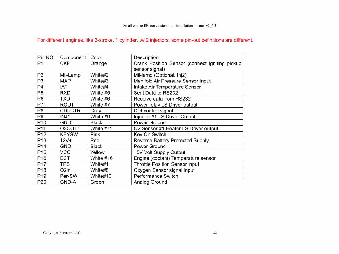
For different engines, like 2-stroke, 1 cylinder, w/ 2 injectors, some pin-out definitions are different.
Pin NO. Component Color DescriptionP1 CKP Orange Crank Position Sensor (connect igniting pickup
sensor signal)P2 Mil-Lamp White#2 Mil-lamp (Optional, Inj2)P3 MAP White#3 Manifold Air Pressure Sensor InputP4 IAT White#4 Intake Air Temperature SensorP5 RXD White #5 Sent Data to RS232P6 TXD White #6 Receive data from RS232P7 ROUT White #7 Power relay LS Driver outputP8 CDI-CTRL Gray CDI control signalP9 INJ1 White #9 Injector #1 LS Driver OutputP10 GND Black Power GroundP11 O2OUT1 White #11 O2 Sensor #1 Heater LS Driver outputP12 KEYSW Pink Key On SwitchP13 12V+ Red Reverse Battery Protected SupplyP14 GND Black Power GroundP15 VCC Yellow +5V Volt Supply OutputP16 ECT White #16 Engine (coolant) Temperature sensorP17 TPS White#1 Throttle Position Sensor inputP18 O2in White#8 Oxygen Sensor signal inputP19 Per-SW White#10 Performance SwitchP20 GND-A Green Analog Ground
Small engine EFI conversion kits - installation manual-v2_5.3
Copyright Ecotrons LLC 83
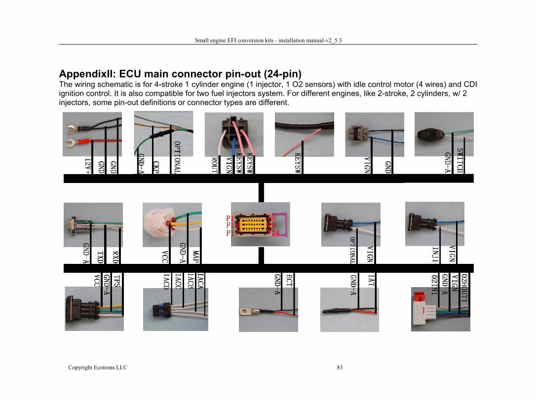
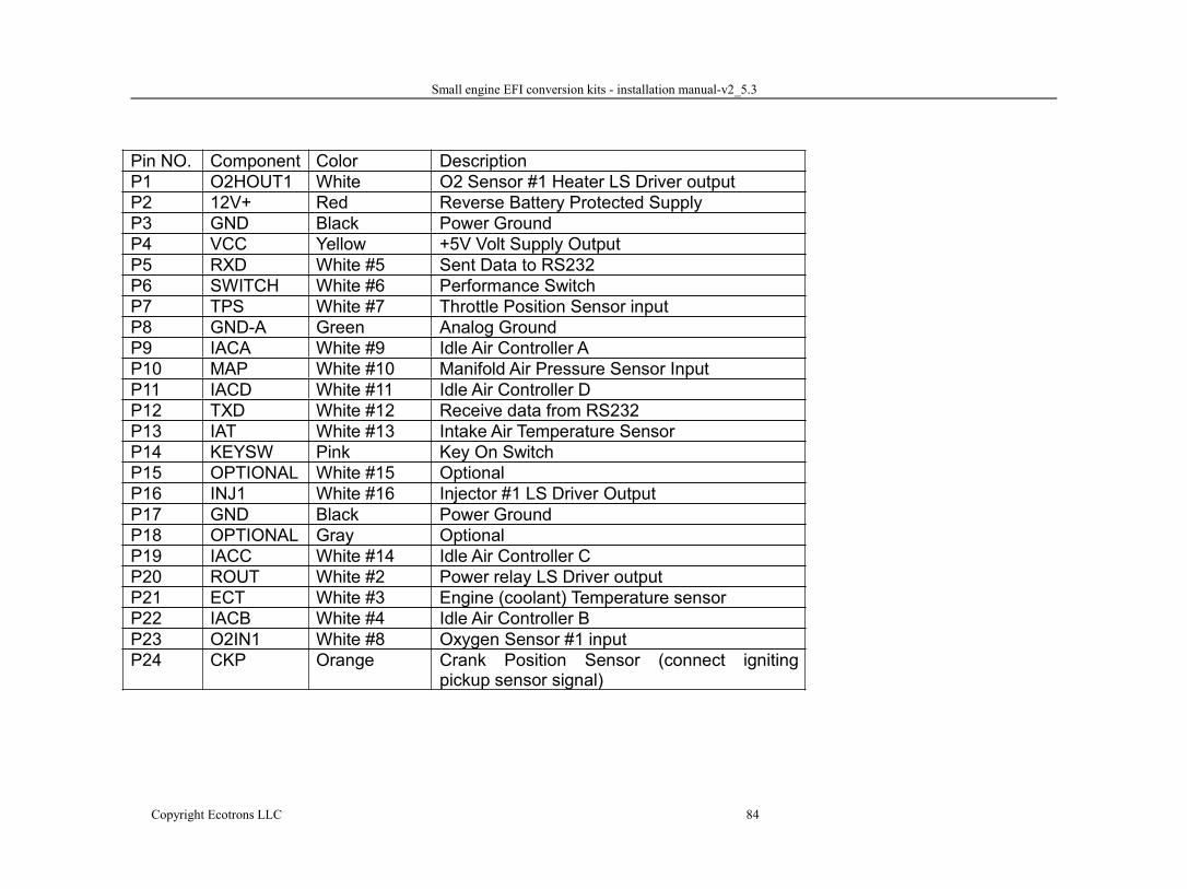
AppendixII: ECU main connector pin-out (24-pin)The wiring schematic is for 4-stroke 1 cylinder engine (1 injector, 1 O2 sensors) with idle control motor (4 wires) and CDIignition control. It is also compatible for two fuel injectors system. For different engines, like 2-stroke, 2 cylinders, w/ 2injectors, some pin-out definitions or connector types are different.
Small engine EFI conversion kits - installation manual-v2_5.3
Copyright Ecotrons LLC 84
Pin NO. Component Color DescriptionP1 O2HOUT1 White O2 Sensor #1 Heater LS Driver outputP2 12V+ Red Reverse Battery Protected SupplyP3 GND Black Power GroundP4 VCC Yellow +5V Volt Supply OutputP5 RXD White #5 Sent Data to RS232P6 SWITCH White #6 Performance SwitchP7 TPS White #7 Throttle Position Sensor inputP8 GND-A Green Analog GroundP9 IACA White #9 Idle Air Controller AP10 MAP White #10 Manifold Air Pressure Sensor InputP11 IACD White #11 Idle Air Controller DP12 TXD White #12 Receive data from RS232P13 IAT White #13 Intake Air Temperature SensorP14 KEYSW Pink Key On SwitchP15 OPTIONAL White #15 OptionalP16 INJ1 White #16 Injector #1 LS Driver OutputP17 GND Black Power GroundP18 OPTIONAL Gray OptionalP19 IACC White #14 Idle Air Controller CP20 ROUT White #2 Power relay LS Driver outputP21 ECT White #3 Engine (coolant) Temperature sensorP22 IACB White #4 Idle Air Controller BP23 O2IN1 White #8 Oxygen Sensor #1 inputP24 CKP Orange Crank Position Sensor (connect igniting
pickup sensor signal)
Small engine EFI conversion kits - installation manual-v2_5.3
Copyright Ecotrons LLC 85
The wiring schematic is for 4-stroke 2 cylinders engine (2 injector, 1 O2 sensors) with idle control motor (4 wires) andinductive Coil control. It can support multi-tooth trigger wheel, such as 12-1, 24-1, 36-2, etc.It is also compatible for two-stroke with two fuel injectors or one fuel injector.
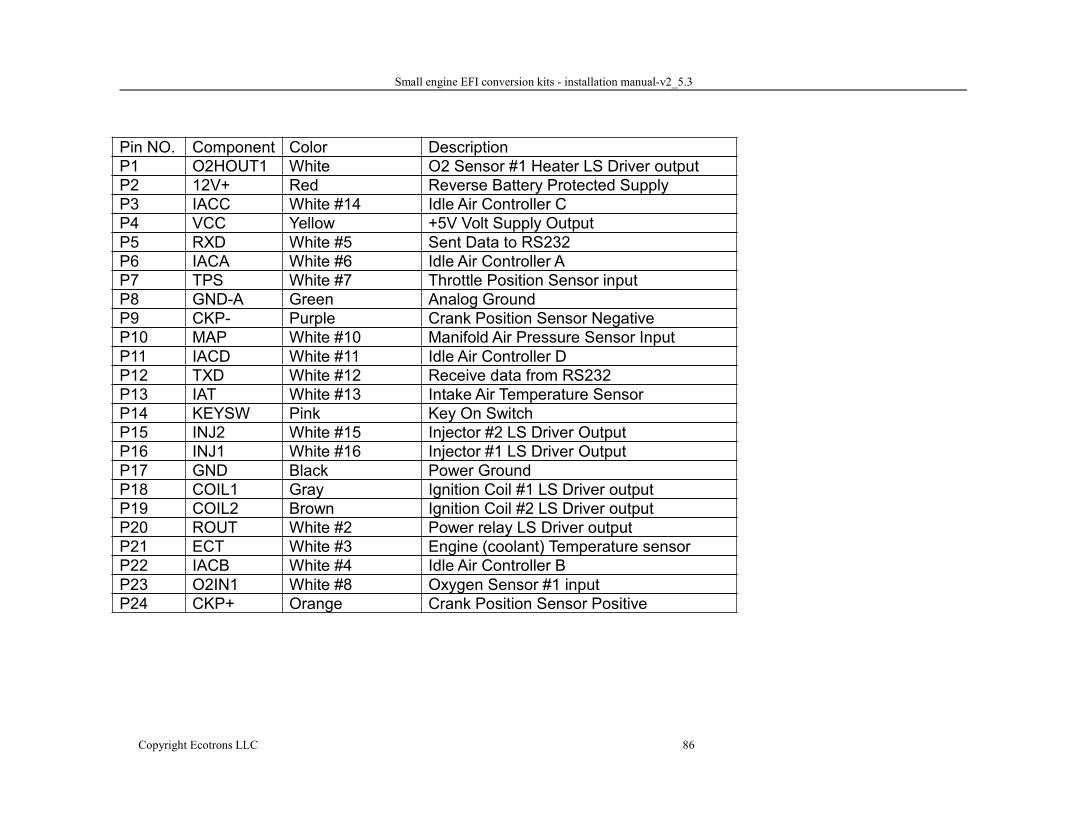
Small engine EFI conversion kits - installation manual-v2_5.3
Copyright Ecotrons LLC 86
Pin NO. Component Color DescriptionP1 O2HOUT1 White O2 Sensor #1 Heater LS Driver outputP2 12V+ Red Reverse Battery Protected SupplyP3 IACC White #14 Idle Air Controller CP4 VCC Yellow +5V Volt Supply OutputP5 RXD White #5 Sent Data to RS232P6 IACA White #6 Idle Air Controller AP7 TPS White #7 Throttle Position Sensor inputP8 GND-A Green Analog GroundP9 CKP- Purple Crank Position Sensor NegativeP10 MAP White #10 Manifold Air Pressure Sensor InputP11 IACD White #11 Idle Air Controller DP12 TXD White #12 Receive data from RS232P13 IAT White #13 Intake Air Temperature SensorP14 KEYSW Pink Key On SwitchP15 INJ2 White #15 Injector #2 LS Driver OutputP16 INJ1 White #16 Injector #1 LS Driver OutputP17 GND Black Power GroundP18 COIL1 Gray Ignition Coil #1 LS Driver outputP19 COIL2 Brown Ignition Coil #2 LS Driver outputP20 ROUT White #2 Power relay LS Driver outputP21 ECT White #3 Engine (coolant) Temperature sensorP22 IACB White #4 Idle Air Controller BP23 O2IN1 White #8 Oxygen Sensor #1 inputP24 CKP+ Orange Crank Position Sensor Positive