sdr-kits › documents › usb-synth-assembly.pdf · 2011-11-25 · sdr-kits.net qrp2000...
TRANSCRIPT

SDR-Kits.net QRP2000 USB-Controlled Synthesizer Kit Assembly v2.06c
SDR-Kits.net
QRP2000 USB-Controlled Synthesizer
1. INTRODUCTION
These instructions are applicable to Printed Circuit Boards V2.03, V2.04 and V2.05 Printed Circuit Boards supplied by SDR-Kits after 24th October 2008.
1. This easy to build project can generate almost any frequency between 3.5MHz and over 200 MHz (160 MHz guaranteed for CMOS) with a resolution of less than 1 Hertz using the Silicon Labs Si570 Programmable Crystal Controlled Oscillator device. An Atmel ATTiny 45 or Atmel ATTiny 85 Micro controller interfaces the Si570 via the I2C bus to the USB bus to a Personal Computer. The frequency of the Si570 can be set using popular SDR Applications like PowerSDR, Winrad, Rocky or a standalone program Si570 USB Control. To use the kit the LibUsb0 driver needs to be installed on the Computer in questions. This driver has been tested with Windows XP, ME, 2000, and Windows 98. For Windows 7 and Vista a Digital Certified Driver should be downloaded, courtesy of Fred Krom PE0FKO. For Linux user there are reports that VK6JBL , usbsoftrock-1.0.1.tar.gz driver is suitable for this Kit.
Contents:2. Bill of Materials
3. Kit Assembly and hardware troubleshooting
4. Driver Installation for Microsoft Windows XP, ME, 20009 and Windows 98
5. Driver installation for Microsoft Windows 7 and Vista (32 and 64 bit versions)
6. Functional Tests
7. Interfacing with Softrock RXTX 6.1 and 6.2
8 PowerSDR Application Setup
9 Rocky SDR Application Setup
10 USB_SYNTH Application and SI570 Calibration
Main Applications:• Full Band or Multi Band coverage of Softrock RXTX V6.1 and V6.2 Transceiver. Soft66RF
Receiver as well as other home brew Receivers, Transmitters and Transceivers
• External Local Oscillator for other SDR hardware Projects – using SI570 USB Control • Wide range oscillator – output frequency programmable in steps < 1 Hz.
• External /PTT output for keying other Transmitter projects/
Basic Specification:
SDR-Kits.net © 2008, 2009, 2010, & 2011 by QRP2000 Design Page 1 of 34

SDR-Kits.net QRP2000 USB-Controlled Synthesizer Kit Assembly v2.06c
• Frequency Range from 3450 kHz up to 160 MHz (in practice up to 250 MHz) for Si570CAC CMOS. For Si570BBC 3450 kHz up to 280 MHz, For Si570BBB LVDS up to 810 MHz (In practice up to 945 MHz). The Si570DBA CML device will cover up to 1417 MHz with no gaps in practice, however this is not guaranteed. If FM modulation is required then use Si571CFC device which in practice provides RF Output up to 250 MHz.
• Stability +/- 50 ppm CMOS or +/0 20 ppm LVDS version – Jitter < 0.4 ps
• Output: Square wave : CMOS version 2.6V pk-pk 15pF , LVDS version 0.7V pk-pk into 100 Ohm. The CMOS version is recommended for Softrock RXTX transceivers. The Si570DBA CML device has 2 independent RF Outputs which match straight into 50 Ohm Load.
• Power Supply: USB Powered or +5V to +12V Power Supply – approx 80mA for Si570 CMOS version, or 100mA for Si570 LVDS version
• PCB size 41 x 48 mm
Acknowledgments: This project was designed by QRP2000 Design team:
Tom - DG8SAQ – Firmware and Host Application Guido PE1NNZ and Alan M0PUB - PowerSDR Support Of USB InterfaceJohn G8BTR (Silent Key) – PCB Design Steve G0XAR - Beta build – Documentation reviewJan G0BBL – Hardware design – Documentation – Kit Production
Thanks also to Alex VE3NEA who kindly provided Rocky USB support for this project andto Fred PE0FKO who developed the Digitally Certified Driver for Windows 7 and Vista OS.
2. BILL OF MATERIALS
Please note: T1 is optional 4:1 transformer for matching Si570 Output to 50 Ohms load. Parts for T1 (43BN2402 core and 60cm #35AWG wire are only supplied with Kit 2 with the Si570BBC000141DG LVDS device.
( ) Inventory of Kit parts is highly recommended – see example Fig 1 below.
Caution: Please observe antistatic precautions for semiconductor devices Do not remove Si570 device from anti-static bag until needed
SDR-Kits.net © 2008, 2009, 2010, & 2011 by QRP2000 Design Page 2 of 34

SDR-Kits.net QRP2000 USB-Controlled Synthesizer Kit Assembly v2.06c
Fig 1 Example Inventory of Kit Parts – (photo by Steve G0XAR)
SDR-Kits.net © 2008, 2009, 2010, & 2011 by QRP2000 Design Page 3 of 34

SDR-Kits.net QRP2000 USB-Controlled Synthesizer Kit Assembly v2.06c
Note: If you have a question about the kit. please contact Jan G0BBL via sdrkits @ gmail.com (remove all spaces in email address)
SDR-Kits.net © 2008, 2009, 2010, & 2011 by QRP2000 Design Page 4 of 34
No in Kit Designation Value Remarks – V2.03 or V2.04 or V2.05 PCB2 C1, C10 10uF 16V Radial12 0.1uF 50V 0805 SMD
2 C4 + 1 spare 1nF 50V 0805 SMD Marked black stripe4 D1, D4, D5, D6 1N40012 D2, D3 3.3 Zener BZX55-3V3 500mW1 Q1 2N3904 NPN Transistor (PTT_Out)1 Q2 2N3906 PNP Transistor (CW_Key_2)1 J1 USB-B Socket1 JP1a shorting jumper 0.1”1 JP1 2 pin header male 0.1” (Power selection USB or external)1 P1 3 pin header male 0.1” (RF Output connector)2 P2 2 pin header male 0.1” (RF Output connector)2 R1, R2 68 Ohm 0.4W (blue grey black gold brown)1 R3 2k2 0.4W Axial (red red black brown brown)1 R4 1M 0.4W (brown black black yellow brown)7 4k7
1 R9 220 0.4W (red red black black brown)1 U1 ATTiny45 or ATTiny 85 Programmed with DG8SAQ firmware1 U2 Silicon Labs
1 U3 LF33ABV 3.3V Regulator TO2201 U4 78M05 5V Regulator TO2201 PCB USB Synthesizer QRP2000 Design v2.03, V2.04 or V2.051 IC Socket 8 pin DIL6 PCB pins 1mm dia
C2, C3, C5. C6, C7, C8, C9, C11, C12 C13, C14 + 1 spare
R5, R6, R7, R8, R10, R11, R12
0.4W (yellow violet black brown brown) or (yellow violet red gold)
CMOS = Si570BBC000141DG Or LVDS = Si570BBC000141DG

SDR-Kits.net QRP2000 USB-Controlled Synthesizer Kit Assembly v2.06c
3. KIT ASSEMBLY
Introduction:
Assembling this kit will involve soldering of surface mount components. This is not difficult but some care and patience is needed. You will need a well lit and clear work surface, a suitable soldering iron with a small tip, some fine (for example 24swg – 0.5mm) resin cored solder and a pair of long tweezers, The type of tweezers should allow you to hold the component GENTLY, otherwise the your tweezers may act as a rocket launcher for tiny SMD parts!!. Firstly make sure that the PCB is held securely to the work surface so it does not move around. Using "Blue Tack" on the edges of the board is one way of doing this. Then identify the pair of lands on the pcb that the surface mount component will be soldered to. Melt a small blob of solder on to one of the lands as a coat. Then, using the tweezers, pick up the the surface mount component and place it across the lands and melt the solder on the pre soldered land. This should effectively hold the component in place whilst you solder it to the unsoldered land. Then resolder it to the to the first land. Then check that the joints are good using a magnifying glass. This all sounds very complicated but it works in practice. If this is your first time using SMD you may wish to find a junk computer card and practice on it first. There are also a number of excellent tutorials on the internet - and no you do not need an oven or an SM workstation. An ordinary soldering iron (preferably temperature controlled is good enough.Good luck!!
Bottom PC mounted components
Fig 2 PCB with all components except Si570 fitted at bottom of boardPlease note: All Capacitors are 0.1uF except C4 which is 1nF. LK is Wirelink
SDR-Kits.net © 2008, 2009, 2010, & 2011 by QRP2000 Design Page 5 of 34

SDR-Kits.net QRP2000 USB-Controlled Synthesizer Kit Assembly v2.06c
( ) Remove any components from PCB so PCB is bare
( ) Check Kit contents against Bill of Materials (Parts for T1 are only supplied in Kit 2)
( ) Place PCB upside down as in fig 2.
( ) Look at Figure 2 to see the exact placement of the SMD capacitors and the PCB terminals. The SMD Capacitors are the small oblong shapes (0805 package), the soldered ends of the PCB terminals show as shiny circles.
( ) Adjust Temperature of Temperature Controlled Soldering Station to correct temperature for soldering SMD components. Temperature depends on type of solder you are using normally 330C or 630F with 60/40 Pb/Sn
( ) Solder SMD 0.1uF 0805 Capacitors C2, C3, C5, C6, C7, C8, C9, C11, C12, C13 and C14 asshown in Figure 2. Then check against Figure 2.
( ) Solder C4 1nF 0805 Capacitor (identified with BLACK mark on strip) next to C3 (Lower right hand side of the board
( ) Check all joints – the board should look like fig 2 below
( ) Note: 6 PCB pins are supplied, If you are using the kit for other purposes then solder PCB pins to suit your particular application
( ) Fit PCB terminals by pressing pin through PCB using a hard metal surface or long nose pliers
making sure that you do NOT damage any of the SMD capacitors in the process and solder at Bottom layer . Typical location of the PCB terminals is: +12V, +5V, GND, CW1, CW2 and PTT as shown in Fig 3 below.
( ) Turn board over
Components mounted on Top ~Layer of PCB (Top Silk)
SDR-Kits.net © 2008, 2009, 2010, & 2011 by QRP2000 Design Page 6 of 34

SDR-Kits.net QRP2000 USB-Controlled Synthesizer Kit Assembly v2.06c
Fig 3 Component lay-out diagramPlease note that “KEYUP” and “OVEN” are currently not used – Optional Connections
Place the board so you can see the components side with the placement (silk screen) diagram in view. Orient the board so that the words “USB SYNTHESIZER” is at the top.
( ) 8 pin IC socket for U1 ensuring that the indentation on the end of the socket matches that on the silk screen
( ) USB Socket – solder pins including the ground connections.
( ) Mount Diodes D1, D2 D3, D4, D5 and D6
Note: observe cathode band and solder observing the polarity of the diode. For D1, D4, D5 and D6 the white band should point toward the hole marked “k”For D2 and D3 the black band should be facing the holes marked “k” next to USB socket J1..
( ) Mount Resistors R1 and R2 (68 Ohm blue grey black gold brown).Mount R3 (2K2 red red black brown brown).R4 (1M brown black black yellow brown).Mount Resistor R9 = 220 Ohm (red red black black)Mount R5, R6, R7, R8, R10, R11 and R12 (4K7 yellow violet black brown brown)
SDR-Kits.net © 2008, 2009, 2010, & 2011 by QRP2000 Design Page 7 of 34

SDR-Kits.net QRP2000 USB-Controlled Synthesizer Kit Assembly v2.06c
Note: When installing the resistors make sure you put the right values in the right places. If in doubt, check the values first using a multimeter.
( ) Fit Capacitor C1 (10uF) and C10 (10uF) – Note: observe polarity and solder
( ) Caution: when handling semiconductors observe anti-static precautions:Preferably wear anti-static Strap or touch unpainted metal ground before handling semiconductors
( ) Fit transistors Q1 and Q2 – Note: observe position against top silk and solder
( ) Fit U3 (LF33ABV) – Note: observe correct position against top silk and solder
( ) Fit U4 (78M05) - Note: observe correct position against top silk and solder
( ) Fit Connector JP1 (2 pin) and solder
( ) Fit Output Connector P1 (3 pin) and solder
( ) Fit Output Connector P2 (2 pin) and solder
Optional LVDS Transformer T1 (supplied with complete Si570 LVDS Kit only)
( ) Cut enameled wire in 3 pieces of 18 cm (7 inches) each and twist uniformly to 4 turns per cm
( ) Wind 5 turns trifiliar on 43BN2402 core supplied. Ensure you do not damage isolation
( ) Scrape and tin the ends of the enameled wires and fit T1 on PCB as shown in circuit diagram
Interim Test Procedure
Note: Jumper JP1 is used to set the Power source for the board on J1. When the jumper JP1 is set, power to the entire board is supplied from the USB port. Alternatively for STANDALONE use (not connected to USB port) , the USB-board may be operated by connecting to either a +7....12V or to a +5V Power source.
With Jumper JP1 removed, operation is only possible when connected to a USB port, however the Si570 Synthesizer chip requires power from an external Power supply. This option reduces the power drawn from the USB Port from about 70...90mA to around 10..15mA
( ) Remove Jumper JP1 from J1-
( ) Connect 12V DC or 5V DC Power to PCB – Note: observe polarity
( ) Check Voltage on U3 pin 3 to Ground - Note: reading should be 3.3V +/- 0.1V
SDR-Kits.net © 2008, 2009, 2010, & 2011 by QRP2000 Design Page 8 of 34

SDR-Kits.net QRP2000 USB-Controlled Synthesizer Kit Assembly v2.06c
( ) Remove Power to PCB
( ) Caution: observe anti-static precautions handling semiconductor
( ) Plug ATTiny45 or ATTiny 85 IC holder for U1 – pin 1 should be aligned towards U3 on the top silk
( ) Connect USB Synthesizer to USB socket of a Personal Computer and measure voltage between U1 Pin 8. Reading should be around 4.3V DC
( ) Disconnect USB cable from USB Synthesizer
Final assembly of Si570 Device
( ) Caution: observe antistatic precautions handling semiconductors
( ) The Si570 device is soldered on the bottom of the PCB. Coat the Si570 pads and the PCB pads for the Si570 with a tiny amount of solder first.
( ) Locate the Dot on the Si570 device and align with pin 1 marked on the PCB. (The Dot is located on the left hand side of bottom line showing the Batchnumber). Apply heat to make the joint and add some more solder as shown in fig 4.
Fig 4 Location of S570 chip – Bottom left pin is Pin 1 aligned with dot on Si571
SDR-Kits.net © 2008, 2009, 2010, & 2011 by QRP2000 Design Page 9 of 34

SDR-Kits.net QRP2000 USB-Controlled Synthesizer Kit Assembly v2.06c
Final Test and commissioning
( ) Remove Jumper JP1 from J1 which is located next to Diode D6
( ) Connect PCB to a 5-12V DC Power Supply and measure Current Consumption typically should be around 70-85mA
( ) Remove External Powersupply.
( ) Set Jumper JP1 to connect J1 Pin 1 and Pin 2 (USB Powered)
( ) If Optional Output Transformer T1 is fitted with Kit 1 Si570 CMOS device solder link between P1 Pin 2 and P1 Pin 3. Remove X2 and Y1 from GND. Twist the X2 and U1 and solder together and leave floating. See Fig 12 Ckt diagram on Page 28.
Photo of completed V2.03 PCB (top)
SDR-Kits.net © 2008, 2009, 2010, & 2011 by QRP2000 Design Page 10 of 34

SDR-Kits.net QRP2000 USB-Controlled Synthesizer Kit Assembly v2.06c
Photo of completed V2.03 PCB (bottom)
USB-Synthesizer output configuration:
Most common application of the USB-Synthesizer uses the Si570 CMOS is as Local Oscillator for Softrock kits or other Receiver and Transmitters. RF Output is obtained from P1 pin 1 and pin 2 as described in chapter 7.. No links are required.
RF output from the module may be configured in several ways depending on the actual application or requirements. Available options are shown in the table below, together with information on wire links required. (use 0805 0 Ohm jumpers – not included in the kit)See also fig 12. Circuit diagram.
SDR-Kits.net © 2008, 2009, 2010, & 2011 by QRP2000 Design Page 11 of 34

SDR-Kits.net QRP2000 USB-Controlled Synthesizer Kit Assembly v2.06c
RF output Configuration for advanced constructors
This completes Kit Assembly
SDR-Kits.net © 2008, 2009, 2010, & 2011 by QRP2000 Design Page 12 of 34
RF Output Configuration Output and typical Application RF Output connection Links1 none required
2 none required
3
4
Note: Earthloop connection: With T1 fitted for unbalanced output fit w ire LINK betw een P2 Pin 2 to GND. Omit for Balanced Output
Si570 CMOS Direct Single Ended Output
3V p-p into > 1KOhm – Use w ith Softrock Projects and other Projects requiring CMOS squarew ave.
RF Output obtained from P1 pin 1 and P1 (Pin 2 = GND)
Si570 LVDS Direct Single ended Output
0.7V p-p – square w ave into 100 Ohm – Direct LVDS output for use w ith LVDS devices above 200 MHz
RF Output obtained from P1 pin 1 and P1 (Pin 2 = GND)
Si570 LVDS Single ended Output from differential LVDS via 1:1:1 Transformer
0.7V p-p – square w ave into 50 ohms Option
RF Output obtained from P2 pin 1 and pin 2.
Fit T1 – On V2.05 PCB f it Link 1 betw een X2/Y1 to GND (not required on V2.03 & V204 PCB)
Si570 CMOS Single ended Output via 4:1 Transformer
+12dBm (0.75V p-p) into 50 Ohms - suitable for driving 50 ohm applications (DBM SBL1 etc)
RF Output obtained from P2 pin 1 and P2 pin 2
Fit T1 and link P1 pin 2 to P1 pin 3. On V2.03 and V2.04 PCB ONLY: do NOT connect T1 X2 and Y1 to GND.

SDR-Kits.net QRP2000 USB-Controlled Synthesizer Kit Assembly v2.06c
3.1 HARDWARE TROUBLE SHOOTING
Before you can use the synthesizer board, you need to perform Driver Installation as described in Chapter 4. Provided the Driver is installed the following DC voltages should be measured on a normal working USB- Synthesizer Kit:
U1 ATTiny45 or ATTiny85 U2 Si570 Device
Pin 1 +4.3V +/- 10% Pin 1 Not connected
Pin 2 +3.3V (no I2C activity) Pin 2 +3.3V
Pin 3 +0.1V (PTT off) +4.3V (PTT on) Pin 3 0V GND
Pin 4 0V GND Pin 4 (CMOS: 2.7V pkpk RF) (LVDS: 0.7V pkpk RF)
Pin 5 0.1V DC (idle USB bus) Pin 5 (CMOS = NC) LVDS: 0.7V pkpk RF out)
Pin 6 +3.3V (no I2C activity) Pin 6 +3.3V VDD
Pin 7 +2.5V to +2.7V(idle USB bus) Pin 7 +3.3V (no I2C activity)
Pin 8 +4.3V +/- 10% VDD Pin 8 +3.3V (no I2C activity)
CW Key 1 Key-up 4.3V DC Key-down 0V CW Key 2 Key-up 4.3V DC Key-down 0V
The most likely problem is “USB enumeration failure” The USB synthesizer is not recognized by the Computer. Tom Baier DG8SAQ has written a paper to help you check this type of failure.
Click HERE to investigate USB-Enumeration failures
SDR-Kits.net © 2008, 2009, 2010, & 2011 by QRP2000 Design Page 13 of 34

SDR-Kits.net QRP2000 USB-Controlled Synthesizer Kit Assembly v2.06c
4. DRIVER INSTALLATION PROCEDURE
Introduction: Before you can use the Kit you must install a DRIVER on each Computer to which the USB-Synthesizer board will be connected to.
Windows XP, ME, 2000, or Windows 98. Traditional Drivers for the USB-Synthesizer kit are successfully used with the following Operating systems:Windows XP, ME, 2000, or Windows 98.For installation see section 4.1 below
Windows 7 and Vista (both 32 and 64 bit OS) require Digitally Signed Driver and a suitable driver is provided courtesy of PE0FKO. See section 4.3 below
LINUX There are a number of reports of successfully operation under Linux, using VK6JBL, usbsoftrock-1.0.1.tar.gz, Driver used on Linux Unbunto Operation System. No further information is available, but check the Softrock Reflector for announcement by other Linux users. http://groups.yahoo.com/group/softrock40/
4.1 Driver Installation Procedure for Microsoft XP Operating System.
• Download Si570 Driver from: http://www.mydarc.de/dg8saq/hidden/SI570_firmware.zip
• Press “Save target as”• Unzip the file SI570_firmware.zip
The following directories will be created
SDR-Kits.net © 2008, 2009, 2010, & 2011 by QRP2000 Design Page 14 of 34

SDR-Kits.net QRP2000 USB-Controlled Synthesizer Kit Assembly v2.06c
Driver Installation Procedure
• Plug in the USB-Synthesizer module into USB port• The following Screen should be displayed:
Problem solving: If this screen is NOT displayed• Check the USB-Synthesizer hardware for correct operation• Is ATTiny45-20 microprocessor plugged in correctly• Has ATTiny45-20 been loaded with correct firmware• Connect the USB-Synthesizer to the USB port of a different computer
After about 5 seconds the message below should be displayed:
SDR-Kits.net © 2008, 2009, 2010, & 2011 by QRP2000 Design Page 15 of 34

SDR-Kits.net QRP2000 USB-Controlled Synthesizer Kit Assembly v2.06c
• Select “No, not this time”• Press “NEXT”
The following screen should now be displayed:
Deselect “Install the software automatically”
SDR-Kits.net © 2008, 2009, 2010, & 2011 by QRP2000 Design Page 16 of 34

SDR-Kits.net QRP2000 USB-Controlled Synthesizer Kit Assembly v2.06c
Select “install from a list or specific location” Press “Next>”
The following screen is displayed
• Deselect “Search removable Media”• Select “Include this location in the search”• Press “Browse”• Select Folder AVR-USB-Driver as shown below
SDR-Kits.net © 2008, 2009, 2010, & 2011 by QRP2000 Design Page 17 of 34

SDR-Kits.net QRP2000 USB-Controlled Synthesizer Kit Assembly v2.06c
• Click “Ok”• Press “Next>”• Software is being installed
When successfully installed, following message displayed:
SDR-Kits.net © 2008, 2009, 2010, & 2011 by QRP2000 Design Page 18 of 34

SDR-Kits.net QRP2000 USB-Controlled Synthesizer Kit Assembly v2.06c
Click “Finish”Message displayed “Found New hardware successfully installed”
4.2 WINDOWS XP, 2000, ME, and 98 DRIVER INSTALLATION VERIFICATION
A check can be made at any time if the driver is properly installed but only if theUSB-module is plugged in
• Press “START”• Press “Control Panel”• Select “System”
Following Screen is displayed
• Select “Hardware”• Select “Device Manager”A folder “LibUSB-Win32 Devices” should be displayed(only when USB-Synthesizer is Plugged-in)
• Press to Expand AVR-USB Device folder
SDR-Kits.net © 2008, 2009, 2010, & 2011 by QRP2000 Design Page 19 of 34

SDR-Kits.net QRP2000 USB-Controlled Synthesizer Kit Assembly v2.06c
Click on “AVR USB Device”Proper operation of the Driver may now be checked
• Select tab “Driver”
The screen below is displayed and options made available to • Remove Driver• Update Driver• Reinstall Driver
SDR-Kits.net © 2008, 2009, 2010, & 2011 by QRP2000 Design Page 20 of 34

SDR-Kits.net QRP2000 USB-Controlled Synthesizer Kit Assembly v2.06c
END OF DRIVER INSTALLATION VERIFICATION
SDR-Kits.net © 2008, 2009, 2010, & 2011 by QRP2000 Design Page 21 of 34

SDR-Kits.net QRP2000 USB-Controlled Synthesizer Kit Assembly v2.06c
5.0 Driver Installation Procedure for Windows 7 or Vista (64 and 32 bits systems)
Download the Digitally Signed LibUSB-Win32 driver from:
http://home.ict.nl/~fredkrom/pe0fko/SR-V9-Si570/PE0FKO-USB-Driver-1.2.0.1.zip
Unpack (unzip) and store in folder. (make a note of location of folder) You should see the following files in the directory:
Plugin the QRP2000 Synthesizer
The System will show the following Window.
SDR-Kits.net © 2008, 2009, 2010, & 2011 by QRP2000 Design Page 22 of 34

SDR-Kits.net QRP2000 USB-Controlled Synthesizer Kit Assembly v2.06c
Select: "Browse for Driver Software on your Computer"Press "Browse" and select the Folder where you unpacked the PE0FKO-USB-Driver.Tick the box "include Subfolders"Press "Next" Windows will show the following screen:
SDR-Kits.net © 2008, 2009, 2010, & 2011 by QRP2000 Design Page 23 of 34

SDR-Kits.net QRP2000 USB-Controlled Synthesizer Kit Assembly v2.06c
Select "Install this driver software anyway"
The Driver will now be installed. When completed the following screen is shown.
This completes the Windows 7 and Vista Driver installation.
SDR-Kits.net © 2008, 2009, 2010, & 2011 by QRP2000 Design Page 24 of 34

SDR-Kits.net QRP2000 USB-Controlled Synthesizer Kit Assembly v2.06c
1. 5.2 To check the Windows 7 or Vista Digitally Certified Driver installation:
Select: Start -Control Panel – System and Security – System – Device Manager
With the QRP2000 US B-Synthesizer must be plugged in the USB Port. The LibUSB-Win32 device should be present as shown below:
END OF WINDOWS 7 AND VISTA Driver verification.
SDR-Kits.net © 2008, 2009, 2010, & 2011 by QRP2000 Design Page 25 of 34

SDR-Kits.net QRP2000 USB-Controlled Synthesizer Kit Assembly v2.06c
6. FUNCTIONAL TESTS
Once driver is installed the USB Synthesizer board can be tested with the application Si570_USB_ Test which can be downloaded from: http://sdr-kits.net/USB/SI570_USB_Test.exe
Start “Si570_USB_Test”Check SI570 i2c adr is set as follows
LVDS Si570BBC000141DG i2c address = 55 Hex CMOS Si570CAC000141DG i2c address = 55 Hex
Note: the address is 55 Hex is valid for all Si570 devices supplied by SDR-Kits.net.The address may be different for Si570 devices obtained from other sources.
Click button “TestUSB” The following screen should be shown.
Setting Frequency:Enter the desired frequency in the Window MHz
Example frequency entered 16.400 MHz click “set freq by value” click “read SI570 registers”
Following screen should be displayed
SDR-Kits.net © 2008, 2009, 2010, & 2011 by QRP2000 Design Page 26 of 34

SDR-Kits.net QRP2000 USB-Controlled Synthesizer Kit Assembly v2.06c
END OF FUNCTIONAL TEST PROCEDURE
7. INTERFACING TO SOFTROCK RXTX V6.1 or V6.2 TRANSCEIVER
Three connections are required to connect the USB-Synthesizer to the RXTX V6.x transceiver as follows:
( ) Prepare a 10cm (4 inch) length of RG174 miniature coaxial cable by removing 1 cm plastic at either end of the cable. Next remove 3mm insulation from the inner conductor at both ends.
Fig 5: Preparation of 10cm 4 inch Coaxial cable
( ) On RXTX PCB, disable the Crystal Oscillator by removing 2 pin Jumper from JP2.
( ) On RXTX PCB remove 2 pin Jumper from JP1.
( ) Solder Inner conductor of coaxial cable to JP1 pin 2 as shown in fig 5 below:
SDR-Kits.net © 2008, 2009, 2010, & 2011 by QRP2000 Design Page 27 of 34
SDR-Kits.net QRP2000 USB-Controlled Synthesizer Kit Assembly v2.06c
( ) Solder Outer conductor of coaxial cable to JP1 pin 4 (Ground) as shown below.
Fig 6: Connection of Coaxial Cable to RXTX PCB JP1
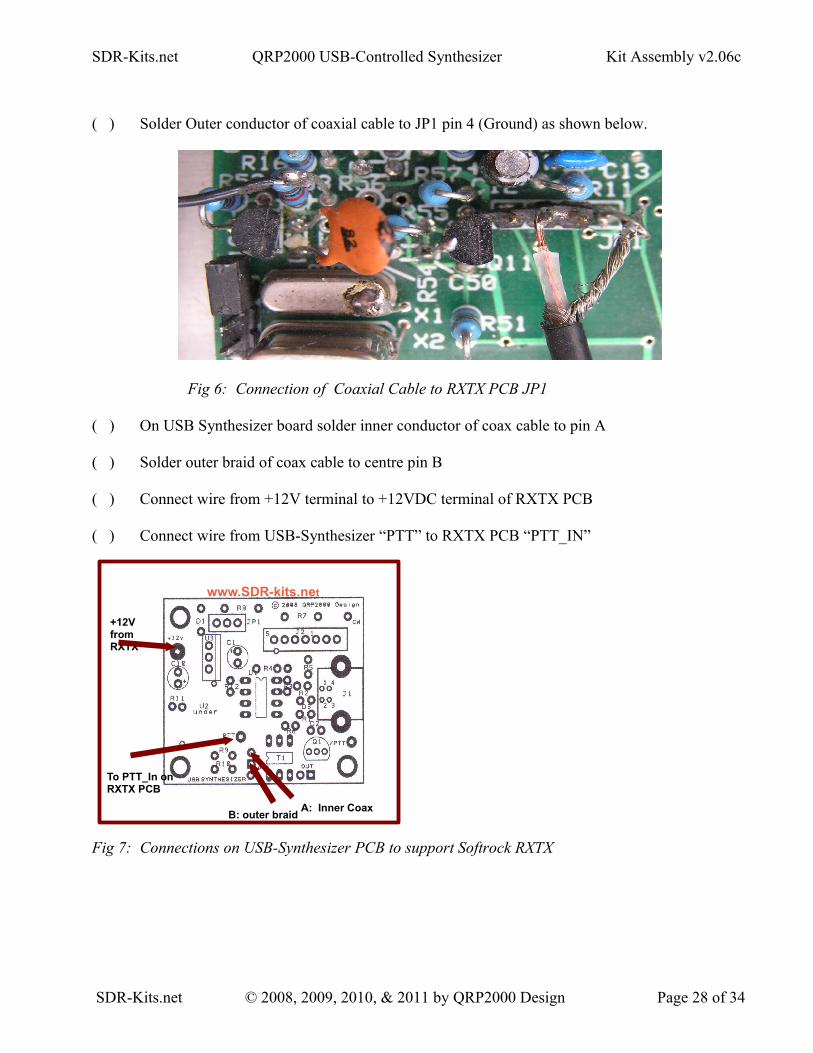
( ) On USB Synthesizer board solder inner conductor of coax cable to pin A
( ) Solder outer braid of coax cable to centre pin B
( ) Connect wire from +12V terminal to +12VDC terminal of RXTX PCB
( ) Connect wire from USB-Synthesizer “PTT” to RXTX PCB “PTT_IN”
Fig 7: Connections on USB-Synthesizer PCB to support Softrock RXTX
SDR-Kits.net © 2008, 2009, 2010, & 2011 by QRP2000 Design Page 28 of 34
A: Inner CoaxB: outer braid
+12V from RXTX
www.SDR-kits.net
To PTT_In on RXTX PCB

SDR-Kits.net QRP2000 USB-Controlled Synthesizer Kit Assembly v2.06c
8 POWERSDR SETUP FOR RXTX USB SUPPORT (updated 16th April 2009)
( ) Download PowerSDR application from Flexradio Systems:Click here which version are currently available for download. Versions recently testedinclude 1.16.1.exe 1.14.0.exe and 1.12.1.exe
( ) Download and install the required version of PowerSDR.exe
We now need to download and install the file Sdr1kUsb.dll (written by Guido PE1NNZ with cooperation from Alan M0PUB) which allows PowerSDR to communicate with USB- Synthesizer board through the driver.
( ) Download the file Sdr1kUsb.dll from Sourceforge repository and save this file in the same directory where you installed PowerSDR in the previous step. (for PowerSDR 1.16.1. typically in C:\Program Files\FlexRadio Systems\PowerSDR v1.16.1
( ) Plug-in USB-Synthesizer board with Jumper JP1 set. The board should berecognized. Start PowerSDR.exe application and open tab “Hardware Config” and tickthe box “USB Adapter” as shown in fig 8 below. Click “Apply”and “Ok”
Fig 8: PowerSDR USB setup Screen
Note: Your existing CW keying arrangements (Parallel port or Serial port) as documented in the PowerSDR documentation continues to be supported. The use of the USB-Synthesizer - Straight CW Key-input is optional.
9 ROCKY V3.6 APPICATION SETUP FOR USB CONTROL
SDR-Kits.net © 2008, 2009, 2010, & 2011 by QRP2000 Design Page 29 of 34

SDR-Kits.net QRP2000 USB-Controlled Synthesizer Kit Assembly v2.06c
The popular Rocky SDR Program by Alex VE3NEA may be downloaded from:http://www.dxatlas.com/Rocky/
To enable USB Support, Start Rocky, Select “VIEW”, Select “Setting”, Select “DSP”Tick “Use Si570-USB, Tick “Multi-Band” and Check Address is set to “85” press “ok”
Fig 9: Rocky USB setup Screen
Note: Your existing CW keying arrangements (Parallel port or Serial port) as documented in the Rocky documentation is still supported. The use of the USB-Synthesizer - Straight CW Key-input is optional.
10 SI570 USB SYNTHESIZER CONFIGURATION AND CALIBRATION
A standalone Si570 Control Application USB_Synth.exe provided courtesy of Tom Baier DG8SAQ may be downloaded HERE
• Typical Applications include control of Si570 as RX Local Oscillator and VXO for TX applications, Test Oscillator or QRSS Beacon etc.
• The frequency may be set to the nearest Hz. And a Multiplication factor (including fractions) and/or Frequency offset (IF offset in MHz) may be specified as shown in the setup screen in fig 11.
SDR-Kits.net © 2008, 2009, 2010, & 2011 by QRP2000 Design Page 30 of 34

SDR-Kits.net QRP2000 USB-Controlled Synthesizer Kit Assembly v2.06c
• “Last Frequency Remember” Option for Standalone applications.
Provision to Calibrate the SI570 to exact frequency
Note: It is important that the correct Grade of the Si570 device fitted is selected for optimum use:
Fig 10: Si570 USB controller USB_Synth.exe
When the SETUP is selected the following screen will be displayed. This shows how the various parameters which may be specified to suit your particular application:
Fig 11: Si570 USB controller USB_Synth.exe Setup Screen
SDR-Kits.net © 2008, 2009, 2010, & 2011 by QRP2000 Design Page 31 of 34

SDR-Kits.net QRP2000 USB-Controlled Synthesizer Kit Assembly v2.06c
10.1 SI570 - SPEED CONFIGURATION
To make optimum use of the capability of the Si570 Device fitted, it is important that the correct Si570 speed grade is selected as shown in Fig 11. For C-grade devices (Si570CAC or Si570BBC) this allows for operation up to the maximum frequency of 280 MHz.
10.2 Si570 FREQUENCY CALIBRATION
Calibration of the Si570 may be easily done using the USB-Synth Application as follows
( ) Set Jumper JP1 and connect USB-Synthesizer to USB Port
( ) On Setup Screen press button “Calibrate to factory Standard start-up frequency”
( ) The SI570 will generate the Standard start-up frequency specified for this device. (For Si570 devices supplied by SDR-Kits this will be nominally 56.320000 MHz)
( ) With accurately calibrated Frequency Counter measure the output frequency of the Si570.
( ) Enter the frequency measured in the window “Factory Calibration Frequency” and press button“Calibrate to factory Standard start-up frequency” to perform calibration. Shift Calibration buttons may also be used to adjust the Oscillator Frequency measured by the Frequency Counter to the value set.
The calibration values are now stored in AVR EEPROM for future use.
10.2 ALTERNATIVE CALIBRATION ROUTINE FOR WWV OR OTHER SOURCE
( ) Tune a Receiver to receive a accurate calibration source like WWV on 10.000 MHz
( ) Set Jumper JP1 and connect USB-Synthesizer to USB Port. Connect a short wire tothe USB_Synth output and couple the output signal to the Receiver until a BEAT frequency with the calibration source is heard.
( ) Operate the 'SHIFT CALIBRATION” buttons until the USB-Synth RF output is ZERO BEAT with the calibration source to complete calibration.
This complete Calibration Routine.
SDR-Kits.net © 2008, 2009, 2010, & 2011 by QRP2000 Design Page 32 of 34

SDR-Kits.net QRP2000 USB-Controlled Synthesizer Kit Assembly v2.06c
10.2 APPENDIX CALIBRATION
Definitions:
Fa = Actual Receive Frequency (Frequency of known Radio Station or Radio Signal published in Frequency list or measured )
Ft = Frequency entered to receive the “known Radio Station”
Fxo = Frequency of the Si570 internal Crystal used in calculate and set “Ft”
Fxn = Corrected Frequency of the Si570 Internal Crystal to set “Ft” to the same frequency as “Fa”
Formula to calculate Fxn = Fxo – (Ft – Fa) / Fa * Fxo
Example = Fxo = 114,300.500 kHzFa = 10,000.000 kHz (WWV reception on 10 MHz)Ft = 9,995.355 kHz Frequency set to receive WWV
Fxn = 114,353.593 (Corrected Crystal frequency – which should be stored (in Hz) for future use by
the program)
END OF DOCUMENT
SDR-Kits.net © 2008, 2009, 2010, & 2011 by QRP2000 Design Page 33 of 34

SDR-Kits.net QRP2000 USB-Controlled Synthesizer Kit Assembly v2.06c
fig 12: USB Synthesizer Circuit Diagram for PCB V2.03, V2.04 & V2.05
SDR-Kits.net © 2008, 2009, 2010, & 2011 by QRP2000 Design Page 34 of 34