sdo oct. - smart digital opticssmartdigitaloptics.com/downloads/sa1t.pdf4 sdo oct | optical current...
TRANSCRIPT

SDO OCT.DIGITAL MEASUREMENT TECHNOLOGY.

3SDO OCT | Optical current transformer
Passive optical network
Primaryconductor
Sensing�ber
Opticaldetector
Opticalsource
Standard single mode�ber optic links
Signal processing/Sampling/
A/D conversion/ Ethernet message
Formatting
Digital outputIEC 61869-9/IEC 61850
Protection andcontrol devices
SubstationEthernet network
OPTICAL CURRENT TRANSFORMERThe SDO OCT is a highly accurate optical current transformer for high voltage systems, based on a fully passive optical transducer (The SDO ICT). The SDO OCT provides a digital measurement solution for metering and protection applications in the next generation of high voltage digital substations.
The operation of the SDO ICT is based on the Faraday Effect. The polarization state of a linearly polarized optical signal is rotated as it travels through a magnetic field. For an optical signal which travels along a closed path, the angle of rotation is proportional to the current enclosed by the path.
SDO ICT. Sensor Head.
› Simplified block diagram of SDO OCT optical current transformer.
Provide full digital measurement data for metering and protection IEC 61850-9-2 LE compatible and IEC 61869-9 ready.
The rotation of the polarization state of the light is measured interferometrically as the phase difference between circularly polarized optical signals which travel in opposite directions around a coil of fibre that encloses the primary.
ARTECHE SDO uses the most advanced fiber sensing technology based on a patented technique that allows construction of passive interferometric transducers. The SDO OCT is composed of three elements:
› SDO ICT sensor head. › Post-type solid and dry polymer insulator with an embedded fiber optic.
› SDO MU merging unit.
Measure AC or DC current with an optical transducer.
SDO MU. Merging Unit.
4 SDO OCT | Optical current transformer
APPLICATIONSSDO OCT is ideally suited for:
› Digital measurement for metering & protection based on the IEC 61850 process bus protocol.
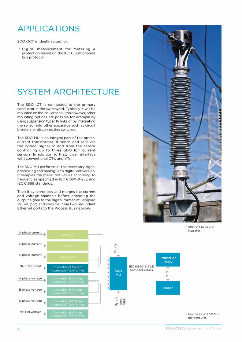
SYSTEM ARCHITECTUREThe SDO ICT is connected to the primary conductor in the switchyard. Typically it will be mounted on the insulator column however, other mounting options are possible for example by using suspension type HV links or by integrating the sensor into other apparatus such as circuit breakers or disconnecting switches.
The SDO MU is an integral part of the optical current transformer. It sends and receives the optical signal to and from the sensor controlling up to three SDO ICT current sensors. In addition to that, it can interface with conventional CT’s and VTs.
The SDO MU performs all the necessary signal processing and analogue to digital conversion. It samples the measured values according to frequencies specified in IEC 61850-9-2LE and IEC 61869 standards.
Then it synchronizes and merges the current and voltage channels before encoding the output signal to the digital format of Sampled Values (SV) and streams it via two redundant Ethernet ports to the Process Bus network.
› Interfaces of SDO MU merging unit.
A phase current
B phase current
C phase current
Neutral current
SDO OCT
Conventional CurrentInstrument Transformer
Conventional VoltageInstrument Transformer
Conventional VoltageInstrument Transformer
Conventional VoltageInstrument Transformer
Conventional VoltageInstrument Transformer
Protection Relay
Meter
IEC 61850-9-2 LE Sampled Values
A phase voltage
B phase voltage
C phase voltage
Neutral voltage
SDO MU
Sup
ply
Syn
ch
SDO OCT
SDO OCT
1PP
S15
88
› SDO ICT head and insulator
5SDO OCT | Optical current transformer
COMPONENT DESCRIPTIONSDO ICT SENSOR HEAD
› Fully passive current transducer based on optical fiber. No power supply required in the switchyard.
› Full galvanic insulation. › No risk of open secondary’s. › Maintenance free. › Reduced dimensions for an optimized substation footprint and easy retrofit integration.
› IEC Class 0.2 accuracy and full linearity over an unlimited dynamic range.
› Single transducer both for metering and for protection applications.
› The current transducer is independent from the voltage level.
› It can be designed for DC measurement. › Redundancy is optional: The sensor head can house up to 2 sensing coils.
SDO MU MERGING UNIT
› 19” 3U Rack mounted electronic signal processing device installed in the protection and control panel.
› Input interface:• 3x SDO ICT.• 4x Conventional VT.• 4x Conventional CT.
› Time Synchronization: 1PPS / 1588. › Digital output via dual Ethernet port. Compliant with IEC 61850-9-2LE and IEC 61869-9 ready.
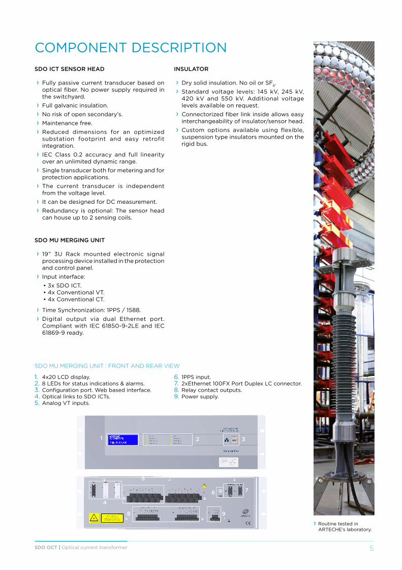
1. 4x20 LCD display.2. 8 LEDs for status indications & alarms.3. Configuration port. Web based interface.4. Optical links to SDO ICTs.5. Analog VT inputs.
1 2 3
4
5
8
6
9
7
SDO MU MERGING UNIT : FRONT AND REAR VIEW
› Routine tested in ARTECHE’s laboratory.
INSULATOR
› Dry solid insulation. No oil or SF6. › Standard voltage levels: 145 kV, 245 kV, 420 kV and 550 kV. Additional voltage levels available on request.
› Connectorized fiber link inside allows easy interchangeability of insulator/sensor head.
› Custom options available using flexible, suspension type insulators mounted on the rigid bus.
6. 1PPS input.7. 2xEthernet 100FX Port Duplex LC connector.8. Relay contact outputs.9. Power supply.

6 SDO OCT | Optical current transformer
TECHNICAL SPECIFICATIONS
SDO ICT SENSOR HEAD
Nominal current User specified for up to 2,500 A(Higher current ratings available under request)
Rated short-time thermal and dynamic current25 kA rms for 3 s, 62.5 kA peak50 kA rms for 1 s, 125 kA peak
75 kA rms for 1 s, 187.5 kA peak
Rated continuous thermal current 2,500 A rms
Accuracy 0.2 s / P20
Bandwidth 2.4 kHz at 80 samples/cycle7.6 kHz at 256 samples/cycle
Weight 15 kg
IP protection IP66
Primary terminal Aluminum
Temperature -40°C to +85°C
Humidity 100% Storage90% Operating
Vibration 1G
Optical connectors 2 x SC/APC
Fiber type for connection with the SDO MU merging unit Standard duplex single mode
INSULATOR (CUSTOMER SPECIFIED)
Maximum system voltage (Um) kV 145 245 420 550
Rated power-frequency withstand voltage kV rms 275 460 630 680
Rated lightning impulse withstand voltage kV peak 650 1,050 1,425 1,550
Rated switching impulse withstand voltage kV peak 1,050 1,175
Minimum creepage distances 31 mm/kV mm 4,495 7,595 13,020 17,050
Minimum flashover distance mm 1,200 2,200 3,250 3,800
Static withstand loads FR N 2,000 2,500 4,000 4,000
MML N 2,000 2,500 4,000 4,000
SML min N 5,000 6,250 10,000 10,000
7SDO OCT | Optical current transformer
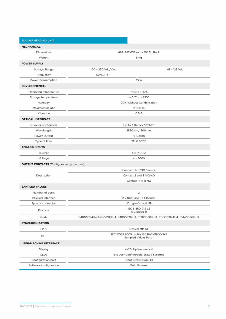
SDO MU MERGING UNIT
MECHANICAL
Dimensions 482x287x133 mm • 19” 3U Rack
Weight 5 Kg
POWER SUPPLY
Voltage Range 100 – 230 Vdc/Vac 48 - 125 Vdc
Frequency 50/60Hz
Power Consumption 25 W
ENVIRONMENTAL
Operating temperature -5°C to +55°C
Storage temperature -40°C to +85°C
Humidity 90% Without Condensation
Maximum height 2,000 m
Vibration 0.5 G
OPTICAL INTERFACE
Number of channels Up to 3 Duplex SC/APC
Wavelength 1550 nm, 1300 nm
Power Output < 10dBm
Type of fiber SM G.652.D
ANALOG INPUTS
Current 4 x 1A / 5A
Voltage 4 x 300V
OUTPUT CONTACTS (Configurable by the user)
Description
Contact 1 NC/NO Service
Contact 2 and 3 NC/NO
Contact 4 to 8 NO
SAMPLED VALUES
Number of ports 2
Physical interface 2 x 100 Base FX Ethernet
Type of connector LC type Optical MM
Protocol IEC 61850-9-2 LEIEC 61869-9
Grids F4000S1I4U4, F4800S1I4U4, F4800S2I4U4, F12800S8I4U4, F15360S8I4U4, F14400S6I4U4
SYNCHRONIZATION
1 PPS Optical MM ST
PTP IEC 61588:2009 profile IEC PAS 61850-9-3Sampled Values Port 1
USER-MACHINE INTERFACE
Display 4x20 Alphanumerical
LEDs 8 x User Configurable: status & alarms
Configuration port Front 10/100 Base TX
Software configuration Web Browser

10 SDO OCT | Optical current transformer
DRAWING DIMENSIONS482465
123,
5
38,5
57
435
324
285
› SDO Merging Unit.