sdn-openflow interface for ops nodes enabling intra...
TRANSCRIPT
1
SDN-OpenFlow interface for OPS
nodes enabling intra-Data Centre
network virtualization
Thesis Report - February – July 2014
Author: Alejandro Ferrer Delgado
Supervisors – Nicola Calabretta and Salvatore Spadaro
Assistant Supervisors – Miao Wang and Fernando Agraz

2

3
Index
Index ..................................................................................................................................... 3
Abstract ................................................................................................................................ 6
Acknowledgements .............................................................................................................. 7
INTRODUCTION............................................................................................................ 8
Introduction ......................................................................................................................... 9
Next Generation Data Centre Networks ....................................................................................................... 9
All-Optical OCS-OPS hybrid DCN proposal: EU Lightness project ............................................................. 9
Unified Control Plane: SDN, OpenFlow & Virtualization ........................................................................ 10
Objective of this Thesis....................................................................................................... 11
SDN & OPENFLOW ..................................................................................................... 12
SDN ..................................................................................................................................... 13
Concept .................................................................................................................................................... 13
Principles .................................................................................................................................................. 13
Elements of a Software Defined Network ................................................................................................... 14
Network virtualization ............................................................................................................................... 16
OpenFlow ........................................................................................................................... 17
Description................................................................................................................................................ 17
OpenFlow Switch....................................................................................................................................... 17
Flow .................................................................................................................................................... 18
Components of an OpenFlow Switch .................................................................................................... 18
The Pipeline ......................................................................................................................................... 19
Optical Support ................................................................................................................................... 20
SDN & OpenFlow applied to DCN ....................................................................................... 21
OPS-OCS HYBRID DC NETWORK.......................................................................... 22
Data Centre Network proposal ........................................................................................... 23
The EU Lightness Project ........................................................................................................................... 23
OPS-OCS Hybrid DCN proposal ................................................................................................................... 23
OPS-Controller Interface .................................................................................................... 25
OPS-Controller Interface Participants................................................................................. 26
OpenDaylight Controller ............................................................................................................................ 26
The Agent ................................................................................................................................................. 27
JavaAgent ............................................................................................................................................ 27
Cagent ................................................................................................................................................. 27
OPS node .................................................................................................................................................. 28
Nomenclature ..................................................................................................................................... 28
Contents .............................................................................................................................................. 28
Example Architecture: OPS 4x4 ............................................................................................................ 29
Interfaces .................................................................................................................................................. 30

4
OpenFlow channel ............................................................................................................................... 30
Loopback UDP sockets ......................................................................................................................... 30
USB link ............................................................................................................................................... 30
Information model .................................................................................................................................... 31
FPGA ......................................................................................................................................................... 32
FPGA Management .............................................................................................................................. 32
Programmatically controlled elements ................................................................................................. 33
OPS Prototype ........................................................................................................................................... 34
DEVELOPMENT OF THE AGENT ........................................................................... 35
The Agent: Design & Development .................................................................................... 36
Overview of Development ......................................................................................................................... 36
Agent’s Code Overview ...................................................................................................... 38
Cagent’s Code ........................................................................................................................................... 38
Cagent: Code Schematic ...................................................................................................................... 38
Cagent: Code Overview........................................................................................................................ 38
Cagent: main.c and global.h behaviour detailed ................................................................................... 41
JavaAgent’s Code ...................................................................................................................................... 45
JavaAgent: Code Schematic ................................................................................................................. 45
JavaAgent: Code Overview ................................................................................................................... 45
JavaAgent: OFListener.java and OpsAg.java behaviour detailed ............................................................ 47
VALIDATION OF THE AGENT ................................................................................ 49
Guide to Run the Agent ...................................................................................................... 50
Requirements: ........................................................................................................................................... 50
Agent’s requirements detailed ............................................................................................................. 50
Requirements for OpenDaylight Controller ................................................................................................ 52
Using OpenDaylight’s GUI to control the OPS node .................................................................................... 53
Starting the OpenDaylight Controller ................................................................................................... 53
Setting up the FPGA to work as an OPS node controlled by ODL: .......................................................... 55
Control the OPS node with OpenDaylight ............................................................................................. 57
Closing the system ............................................................................................................................... 59
Validation Scenarios ........................................................................................................... 60
Scenario 1: Assign flows to different virtual slices ...................................................................................... 60
Results................................................................................................................................................. 62
Scenario 2: Virtual management of several OPS nodes .............................................................................. 66
Results................................................................................................................................................. 67
FUTURE WORK & CONCLUSIONS ......................................................................... 68
Further Developing the Agent ............................................................................................ 69
Requirements for further developing the code ........................................................................................... 69
Configuration options .......................................................................................................................... 70
Future Work ....................................................................................................................... 72
Priority future work ................................................................................................................................... 72
Extend the Architecture ....................................................................................................................... 72

5
DMA communication ........................................................................................................................... 72
Further OF extensions.......................................................................................................................... 73
Other desirable future work ...................................................................................................................... 74
Security ............................................................................................................................................... 74
Migrate to a Dedicated Platform .......................................................................................................... 74
Change the FPGA ................................................................................................................................. 75
Conclusion .......................................................................................................................... 76
BIBLIOGRAPHY & REFERENCES .......................................................................... 77
Acronyms............................................................................................................................ 78
Bibliography ....................................................................................................................... 79
Online References ..................................................................................................................................... 79
Publications .............................................................................................................................................. 81
Documentation ......................................................................................................................................... 81
ANNEXES ....................................................................................................................... 82
Annex A: Reference Tables for OPS4x4 .............................................................................. 83
Management Values ................................................................................................................................. 83
Register count and location ....................................................................................................................... 83
Annex B: Publications & Awards ........................................................................................ 84
Publications .............................................................................................................................................. 84
Awards ..................................................................................................................................................... 84
Annex C: Source files & Contact details .............................................................................. 85
Agent’s Code and source files .................................................................................................................... 85
Contact Details.......................................................................................................................................... 85
6
Abstract
This thesis reports the outcome of the joint collaboration I made with the ECO department in the
Electrical Engineering faculty of the Technische Universiteit Eindhoven (TU/e) during my stay in the
Netherlands in the framework of the Erasmus interchange Program.
The main goal was developing a software (from now on, the Agent) that will, on one hand, control
and manage the FPGAs (Field Programmable Gate Arrays) which are part of an Optical Packet Switch
prototype, and on the other hand communicate for the first time a switch like that with an external
entity called Controller through the OpenFlow protocol so that it can be eventually integrated in a
SDN Data Centre.
This report has two purposes: to present the problem I was trying to solve by creating the software
mentioned and also that this document could be used as a comprehensive manual in order to be
able to use and/or further extend the tool developed.
This work was part of the European FP7 LIGHTNESS project (№ 318606).

7
Acknowledgements
First of all, a deeply grateful acknowledgement to Fernando Agraz (UPC) and Miao Wang (TU/e),
with whom I had the privilege of working very closely and whose help has been so capital for me.
Then, to professors Salvatore Spadaro (UPC) and Nicola Calabretta (TU/e) for welcoming and
introducing me to the world of research in general and this project in particular.
Finally, I would like to thank my family and Marta, my girlfriend, for their support and allowing me to
live this wonderful experience.

8
Introduction
9
Introduction
Next Generation Data Centre Networks Today’s multi-tier Data Centre Network (DCN) architectures are unable to provide the flexibility,
scalability, programmability and low-complexity that are required to deliver new applications and
services, in an efficient and cost-effective way, while matching their requirements, as they are
limited to semi-automated or static procedures to provide connectivity.
For this reason, next generation data centres are required to provide more powerful IT capabilities,
more bandwidth, more storage space, slower time to market for new services to be deployed and
lower cost. The trends of future data centres are towards resource virtualization and cloud
computing, with converged IT and network resources management to design and implement
practicable and easily maintainable data centres which fully meet these requirements.
All-Optical OCS-OPS hybrid DCN proposal: EU Lightness project The European Union Lightness Project aims to design, implement and validate a high-performance
and scalable Data Centre Network (DCN) architecture for ultra-high bandwidth, dynamic and on-
demand network connectivity.
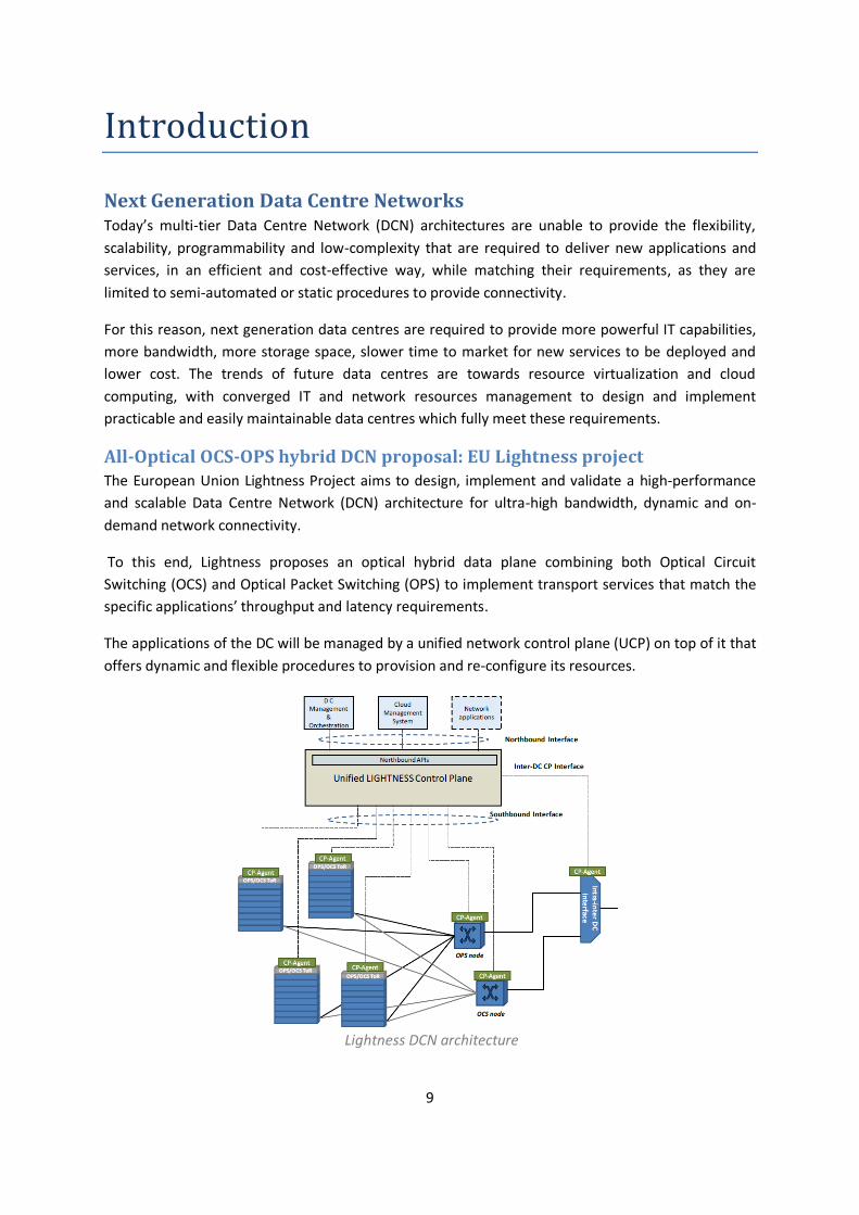
To this end, Lightness proposes an optical hybrid data plane combining both Optical Circuit
Switching (OCS) and Optical Packet Switching (OPS) to implement transport services that match the
specific applications’ throughput and latency requirements.
The applications of the DC will be managed by a unified network control plane (UCP) on top of it that
offers dynamic and flexible procedures to provision and re-configure its resources.
Lightness DCN architecture
10
The proposed integration of both switching technologies in the intra-DC network environments will
provide a scalable, flexible and ultra-high capacity transport network. On one hand, OCS behaves
very efficiently for supporting long-lived data flows ensuring their QoS guarantees. On the other
hand, OPS takes advantage on the statistical multiplexing of optical resources to achieve highly
flexible transport services with low end-to-end latencies.
Unified Control Plane: SDN, OpenFlow & Virtualization These technologies combined seem to offer all the tools necessary to allow for the implementation
of next generation DCNs in general and the Lightness project proposal in particular.
The SDN paradigm will allow a separated, centralized control plane that, through the use of
virtualization and abstraction, can maintain a global view of the state and characteristics of the
underlying network and communicate it to the applications running on top of it so that they can
make well informed decisions about its management thus providing automated connection
establishment, service/devices monitoring, on-line optimization of network connections spanning
multiple optical technologies, and matching QoS requirements for data centre services and
applications.
Specifically, the separation of control plane and data plane makes the SDN a suitable candidate for
an integrated control plane supporting heterogeneous technologies within data centres.
Additionally, the use of the OpenFlow protocol, a vendor and technology agnostic interface between
the Controller and the switches, would allow this centralized control plane to programmatically
control all the underlying network elements, be it physical or virtual, according to the requirements
of the applications.
11
Objective of this Thesis
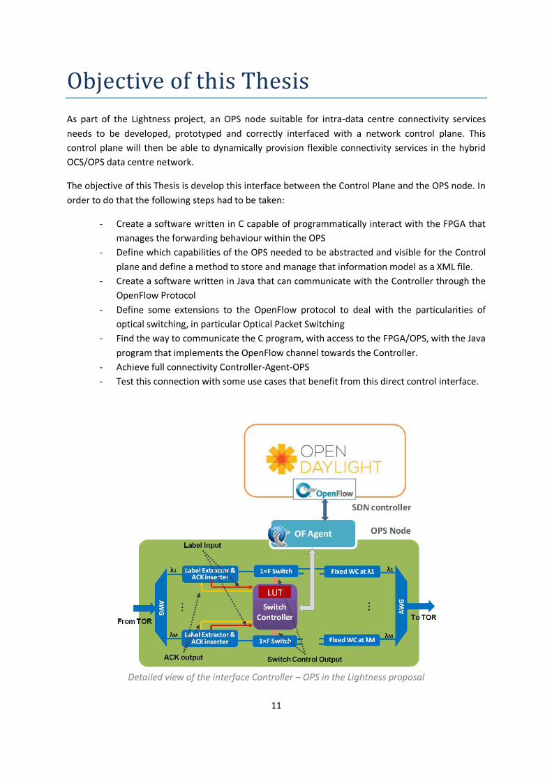
As part of the Lightness project, an OPS node suitable for intra-data centre connectivity services
needs to be developed, prototyped and correctly interfaced with a network control plane. This
control plane will then be able to dynamically provision flexible connectivity services in the hybrid
OCS/OPS data centre network.
The objective of this Thesis is develop this interface between the Control Plane and the OPS node. In
order to do that the following steps had to be taken:
- Create a software written in C capable of programmatically interact with the FPGA that
manages the forwarding behaviour within the OPS
- Define which capabilities of the OPS needed to be abstracted and visible for the Control
plane and define a method to store and manage that information model as a XML file.
- Create a software written in Java that can communicate with the Controller through the
OpenFlow Protocol
- Define some extensions to the OpenFlow protocol to deal with the particularities of
optical switching, in particular Optical Packet Switching
- Find the way to communicate the C program, with access to the FPGA/OPS, with the Java
program that implements the OpenFlow channel towards the Controller.
- Achieve full connectivity Controller-Agent-OPS
- Test this connection with some use cases that benefit from this direct control interface.
Detailed view of the interface Controller – OPS in the Lightness proposal
12
SDN & OpenFlow

13
SDN
Concept Software-defined networking (SDN) is a control framework that supports programmability of
network functions and protocols by decoupling the control plane (which decides how to handle the
traffic) and the data plane (which forwards it according to decisions that the control plane makes).
This technology also allows the underlying infrastructure to be abstracted and used by applications
and network services as a virtual entity.
Separating control and forwarding functions allows SDN controllers to apply multiple different
network technologies, making SDN a suitable candidate as a Unified Control Plane.
Nevertheless, there are different confronted views about how this separated control plane should
be implemented; some defend a software-based centralized control plane, while others propose a
more logically distributed software control.
As for now, the most extended option, up to the point where it is considered the only way to
actually implement software defined networking, is the first one: implementing the Control plane
through a logically centralized software entity called Controller.
Principles The key principle of SDN is the separation between the Control Plane and the Data Plane
This fact greatly simplifies network devices belonging to the Data Plane, since they no longer need to
understand and process thousands of protocol standards but merely accept instructions through a
predefined channel from the Control Plane, namely the SDN controllers.
This separation is the foundation of the three principles that rule a Software Defined Network:
Logically centralized intelligence
By centralizing network intelligence, decision-making is facilitated based on a global view of the
network, as opposed to today’s networks, where the nodes are the ones making decisions but have
only a very limited vision of the network and are unaware of its overall state.
This does not imply that the controller is physically centralized. For performance, scalability, and/or
reliability reasons, the logically centralized control can be distributed so that several physical
controller instances cooperate to perform their duties.
Apart from that, a single software control program can control multiple data-plane elements and has
direct control over the state of the data-plane elements via a well-defined API.

14
Programmability
SDN allows network managers to configure, manage, secure, and optimize network resources
through the use of open APIs for applications to interact with the network. Such programmability
will make the network configuration more automatable and, at the same time, wildly adaptable.
In addition, through the use of open standards which are vendor-agnostic, a simplified network
design and operation can be achieved because the dependence to multiple, vendor-specific devices
and protocols can be avoided.
Abstraction
In an SDN network, the software-based Controllers maintain a global abstracted view of the network
and its elements so that this simplified view can be used to extract the relevant aspects for a
particular decision-making process.
Not only that, this abstracted view of the state and resources can be provided through an open
interface to higher level entities, which are called applications and will be defined in the next
section, which run on top of the controllers and use this simplification of the underlying network
capabilities and state to perform a certain task, be it searching the shortest path between two nodes
or establishing a video streaming communication.
Classical view of the elements within a SDN network
Elements of a Software Defined Network The SDN architecture consists of three distinct layers that are accessible through open APIs:
The Application Layer consists of the end-user applications that explicitly, directly, and
programmatically communicates their network requirements and desired network behaviour to the
Controller.
As a whole, these applications may have a myriad of different forms and purposes.
15
The Control Layer provides the logically centralized control functionality that supervises the
network behaviour (e.g. network paths, forwarding behaviour, etc.) through open interfaces.
Typically, the control plane is instantiated as a single, high-level software entity in charge of
translating the requirements from the SDN Apps into low-level rules down to the Data Plane (having
exclusive control over an abstract set of data plane resources) and, at the same time, providing to
those applications an abstract view of the network which usually includes statistics and events.
The Infrastructure Layer consists of the network elements and devices that provide packet
switching and forwarding of traffic.
There is no need to use specialized switches in a SDN network, but actions must be taken to ensure
that these elements and devices of the Data plane are able to understand and enforce the
instructions received from the Controller.
Interestingly, even if the key principle of SDN is the decoupling of control and data planes, it is
sometimes needed that the data plane itself exercises some control, even if it is on behalf of the SDN
controller. The decoupling principle can be interpreted in such a way that it still allows an SDN
controller to delegate control functions to the data plane, subject to a requirement that these
functions behave acceptably; that is, the controller should never be surprised.
Interfaces
Each interface is implemented by a driver-agent pair, the agent representing the “southern”, or
infrastructure facing side and the driver representing the “northern”, top, or application facing side.
There are two major interfaces that connect the different layers:
Northbound Interface
It is the one that communicates the Apps from the Application layer with the Controllers. Through
the open APIs defined for this interface (such as OpenStack) the applications can request
information about the network state from the control plane and, according to it, ask for the
enforcement of some network control measures such as the provisioning of resources or the
establishment of a communication between data plane elements.
In this case the agent would belong to the Control plane while the driver would be located in the
Application plane.
Southbound Interface
Through this interface defined between an SDN Controller and the network elements from the
Datapath it is possible to provide programmatic control of forwarding operations from the Controller
to the Data Plane element and, in the opposite direction, capabilities advertisement, statistics
reporting, and event notification.
This interface is expected to be open, vendor-neutral and easily interoperable. One example of such
type of southbound interface would be the OpenFlow protocol.
In this case the agent would be located in the network elements from the Data Plane (namely the
switches) and the driver would belong to the Controller side of the communication.
16
Network virtualization Network virtualization consists of instantiating many distinct logical networks on top of a single,
shared, physical network infrastructure so that, at the end, the abstraction of the network is
decoupled from the underlying physical equipment.
By allowing multiple virtual networks to run over a shared infrastructure, each virtual network can
have a much simpler, more abstract, topology than the underlying physical network.
Relationship between Network Virtualization and SDN
It is important to realize that SDN and network virtualization are independent concepts:
Virtualization allows dividing a network into segments, or the creation of software-only networks
between virtual machines. Its goal is to improve automation and network management. SDN instead
separates the control and data planes with the goal of achieving overall programmability.
For instance, many years before the conception of SDN network equipment has supported the
creation of virtual networks like VLANs and VPNs.
Network virtualization does not require SDN and SDN does not imply network virtualization, but
both benefit from each other:
- Network virtualization allows evaluating and testing SDN networks. For instance Mininet (an SDN network emulator) uses process-based virtualization to run
multiple virtual OpenFlow switches, end hosts, and SDN controllers, each as a single process on
the same physical (or virtual) machine.
- SDN enables network virtualization. On one hand, virtualizing a conventional router is difficult, because each virtual component
needs to run its own instance of control-plane software.
On the other hand, virtualizing a SDN switch is much simpler because the control functionalities
have been stripped away from it. So that, it is possible to divide the traffic space into slices,
where each slice has a share of network resources and is managed differently by the SDN
controller or even by completely different SDN controllers.
17
OpenFlow
Description The OpenFlow protocol, first proposed by the Stanford University in 2008, is an open standard
communications interface defined between the control and forwarding layers of an SDN
architecture. The OpenFlow Standard allows direct access and manipulation of the forwarding plane
of network devices such as switches, both physical and virtual, by a SDN controller.
The Open Networking Foundation (ONF) is the organ tasked with promoting the adoption of SDN by
developing and standardizing the Open Flow protocol since 2011.
It is worth noting that it’s possible to implement SDN with a southbound interface different from
OpenFlow. In other words; OF is meant for SDN, but SDN doesn’t necessarily imply OF.
Nevertheless, a protocol such as the OpenFlow protocol allows the actual moving of network control
out of networking switches to a logically centralized control software, thus effectively separating the
control plane form the data plane.
As a Southbound Interface, the OF protocol must implemented on both sides communication
between network infrastructure devices and the SDN control software.
Since OpenFlow allows the network to be programmed on a per-flow basis, an OpenFlow-based SDN
architecture provides extremely granular control, enabling the network to respond to real-time
changes. What OpenFlow doesn’t do is providing the configuration and management functions that
are needed to allocate ports or assign IP addresses. Configuration protocols, like OF-Config proposed
by the ONF, would be necessary for this task.
OpenFlow Switch An OpenFlow Switch, the representation of the actual underlying switch that the SDN controller
intends to manage through this southbound interface, consists of one or more OpenFlow tables and
a group table, which perform packet lookups and forwarding, and one or more OpenFlow channels
to the external controller.
Using the OpenFlow switch protocol, the controller can add, update, and delete OpenFlow entries in
OpenFlow tables, both reactively (in response to packets) and proactively. Each OpenFlow table in
the switch contains a set of OpenFlow entries, which manage the actual forwarding within the
switch, which takes place during in the pipeline.

18
An OpenFlow-enabled switch can be virtual (running only on software) or physical. Among the
physical there are 2 types: The ones built with OpenFlow in mind and the legacy switches with a
firmware update that implements at least OpenFlow v1.0.
Flow A flow can be defined as any combination of L2, L3 and L4 packet header, as well as L1/L0 circuit
flows, so that switching at different network layers to be combined. Once assigned, they have
counters and metrics attached to it and retrievable by the controller.
When we use the abstraction of a flow in a packet switched network, we effectively blur the
distinction between packets and circuits and regard them both simply as flows in a flow switched
network. That is the reason why the OpenFlow protocol has been widely regarded as an enabler for
a truly unified control plane.
Block elements of an OpenFlow Switch
Components of an OpenFlow Switch An OpenFlow Switch consists of:
Ports
Where packets enter or exit the switch and, by extension, the OpenFlow pipeline. It can be a physical
port, a logical port defined by the switch, or a reserved port defined by the OpenFlow protocol.
The protocol can be used make the controller aware of the characteristics of these ports and
retrieve counters and statistics from them.
OpenFlow tables
An OpenFlow Switch can have one or more OpenFlow tables and a group table, which perform
packet lookups and forwarding. They are part of the pipeline of the Switch and will be further
described in that section.
19
OpenFlow Channel:
It is the interface that connects through TCP or TLS each OpenFlow switch to a controller. Through
this interface, the controller configures and manages the switch, receives events from it, and sends
back packets in response to those events.
The OpenFlow messages, defined in the protocol, are sent over the OpenFlow Channel and can be a
request, a reply, a control message or a status event.
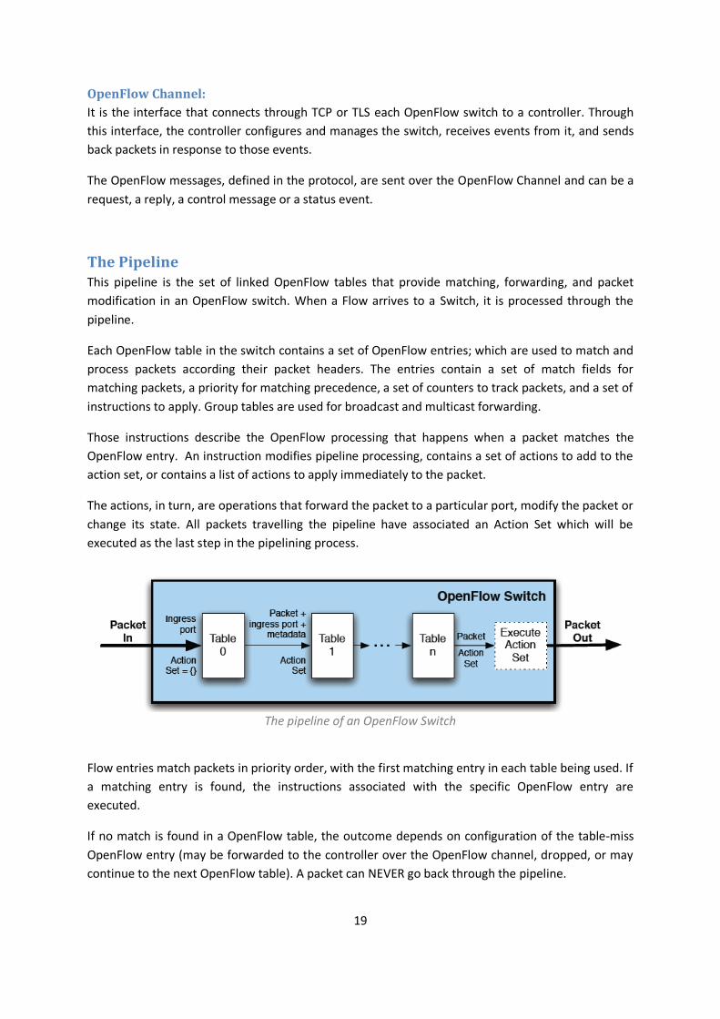
The Pipeline This pipeline is the set of linked OpenFlow tables that provide matching, forwarding, and packet
modification in an OpenFlow switch. When a Flow arrives to a Switch, it is processed through the
pipeline.
Each OpenFlow table in the switch contains a set of OpenFlow entries; which are used to match and
process packets according their packet headers. The entries contain a set of match fields for
matching packets, a priority for matching precedence, a set of counters to track packets, and a set of
instructions to apply. Group tables are used for broadcast and multicast forwarding.
Those instructions describe the OpenFlow processing that happens when a packet matches the
OpenFlow entry. An instruction modifies pipeline processing, contains a set of actions to add to the
action set, or contains a list of actions to apply immediately to the packet.
The actions, in turn, are operations that forward the packet to a particular port, modify the packet or
change its state. All packets travelling the pipeline have associated an Action Set which will be
executed as the last step in the pipelining process.
The pipeline of an OpenFlow Switch
Flow entries match packets in priority order, with the first matching entry in each table being used. If
a matching entry is found, the instructions associated with the specific OpenFlow entry are
executed.
If no match is found in a OpenFlow table, the outcome depends on configuration of the table-miss
OpenFlow entry (may be forwarded to the controller over the OpenFlow channel, dropped, or may
continue to the next OpenFlow table). A packet can NEVER go back through the pipeline.
20
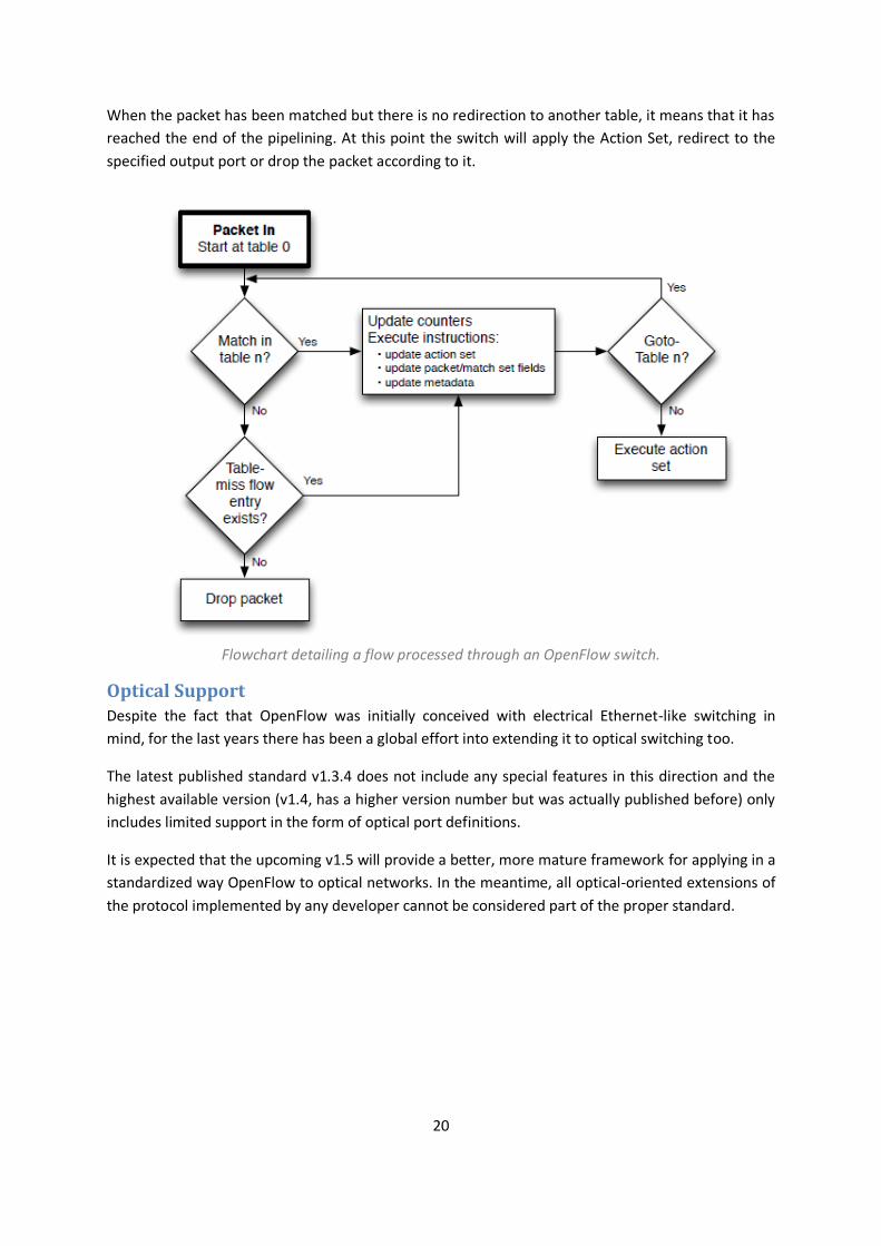
When the packet has been matched but there is no redirection to another table, it means that it has
reached the end of the pipelining. At this point the switch will apply the Action Set, redirect to the
specified output port or drop the packet according to it.
Flowchart detailing a flow processed through an OpenFlow switch.
Optical Support Despite the fact that OpenFlow was initially conceived with electrical Ethernet-like switching in
mind, for the last years there has been a global effort into extending it to optical switching too.
The latest published standard v1.3.4 does not include any special features in this direction and the
highest available version (v1.4, has a higher version number but was actually published before) only
includes limited support in the form of optical port definitions.
It is expected that the upcoming v1.5 will provide a better, more mature framework for applying in a
standardized way OpenFlow to optical networks. In the meantime, all optical-oriented extensions of
the protocol implemented by any developer cannot be considered part of the proper standard.
21
SDN & OpenFlow applied to DCN
One of the existing use cases that would benefit more from the introduction of the SDN model that
deploys a centralized control panel are the Data Centres.
The most common issue that a SDN network would address for a DC is its inability to support the
requirements of server virtualization in a scalable way, as it enables the programmable automatic
provision of those virtual networks and appliances and general resources instead of depending on a
much slower human-mediating provisioning.
But these are not the only requirements for a SDN applied to a Data Centre:
Network endpoint mobility in the form of virtual machines moving from one server to the other and
rapid growth in the overall number of VMs and therefore IP endpoints must be taken into
consideration, as they will need to be served and provisioned in real time.
Networks within the DC must be capable of being reconfigured rapidly to achieve the elasticity
needed to optimize the pooled resources while making sure through a fine granular policy
management that the control of a certain subnet or slice does not affect negatively a different slice,
even if they share underlying resources. OpenFlow‘s flow-based control model allows the application
of policies at the required granular level, be it session, user, device, or application levels, in a highly
abstracted, automated fashion
A Centralized SDN control software can control any OpenFlow-enabled network device from any
vendor, including switches, routers, and virtual switches. By centralizing network control and making
state information available to higher-level applications, an SDN infrastructure can better adapt to
dynamic nature of Data Centre’s traffic.
By virtualizing the network infrastructure and abstracting it from individual network services, SDN
and OpenFlow give the ability to detail the behaviour of the network and introduce new services and
network capabilities in a matter of hours, thus allowing a higher rate of innovation
Also, as it eliminates the need to individually configure network devices each time an end point,
service, or application is added or moved, or a policy changes, the likelihood of network failures due
to configuration or policy inconsistencies is greatly reduced, as well as the required operational
overhead.
22
OPS-OCS Hybrid DC Network

23
Data Centre Network proposal
The EU Lightness Project The Lightness project is a 3-year Single Target Research Project (STREP) with funding from the
European Union’s Seventh Framework Programme for research, technological development and
demonstration started on November, 2012. Its main objective is the design, implementation and
experimental evaluation of a high-performance and scalable Data Centre Network (DCN)
architecture for ultra-high bandwidth, dynamic and on-demand network connectivity.
To this end, Lightness works towards the demonstration of a high-performance optical hybrid data
plane for DCN combining both Optical Circuit Switching (OCS) and Optical Packet Switching ( OPS) to
implement transport services that match the specific applications’ throughput and latency
requirements. These applications will be managed by a unified network control plane (UCP) on top
of the DCN that offers dynamic and flexible procedures to provision and re-configure its resources.
The proposed integration of both switching technologies in the intra-DC network environments will
provide a scalable, flexible and ultra-high capacity transport network. On one hand, OCS behaves
very efficiently for supporting long-lived data flows ensuring their QoS guarantees. On the other
hand, OPS takes advantage on the statistical multiplexing of optical resources to achieve highly
flexible transport services with low end-to-end latencies.
OPS-OCS Hybrid DCN proposal Next generation data centres are expected to provide high flexibility and scalability, not only in
terms of computing and storage resource utilization, but also in terms of network infrastructure
design and operation, including disaster recovery and security functions. In particular, flexibility is
critical in today’s data centre environments and will be imperative for their businesses in the near
future.
IT and network demands fluctuate depending on the specific deployed services and customer
workloads, with different patterns during the day (e.g. peaks during business hours or specific
business cycles). Data centres also have to cope with more long-term variations such as customers’
growth and deployment of new IT services. In other words, future data centres need to be dynamic
environments with flexible IT and network infrastructures to optimize performances and resources
utilization.
LIGHTNESS proposes a scalable and ultra-high capacity and connectivity transport networks for intra
data centre based on a new OPS/OCS fabric coupled to a unified control plane that allow for
replacing the traditional tiered networks with a flat fabric that interconnects edge node interfaces
with high bandwidth, low latency network irrespective of the node location, consuming much lower
energy.
The integration of both OCS and OPS optical switching technologies in the intra-DC network
environments fulfils the requirements of emerging applications running in data centres in terms of
24
ultra-high bandwidth and low network latency. OCS will be applied when supporting long-lived
smooth data flows and OPS will take advantage of the statistical multiplexing of optical resources to
achieve highly flexible transport services with very low end-to-end latencies.
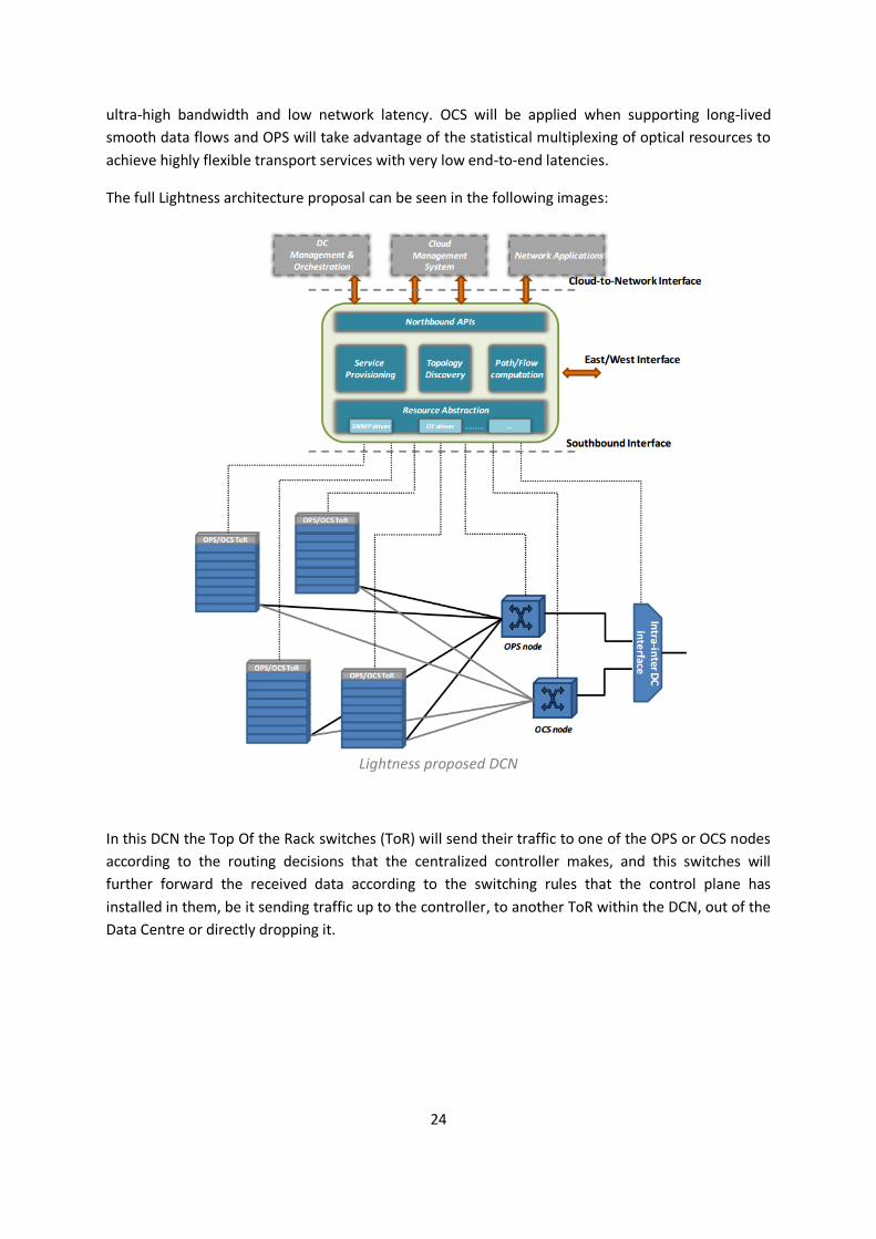
The full Lightness architecture proposal can be seen in the following images:
Lightness proposed DCN
In this DCN the Top Of the Rack switches (ToR) will send their traffic to one of the OPS or OCS nodes
according to the routing decisions that the centralized controller makes, and this switches will
further forward the received data according to the switching rules that the control plane has
installed in them, be it sending traffic up to the controller, to another ToR within the DCN, out of the
Data Centre or directly dropping it.
25
OPS-Controller Interface
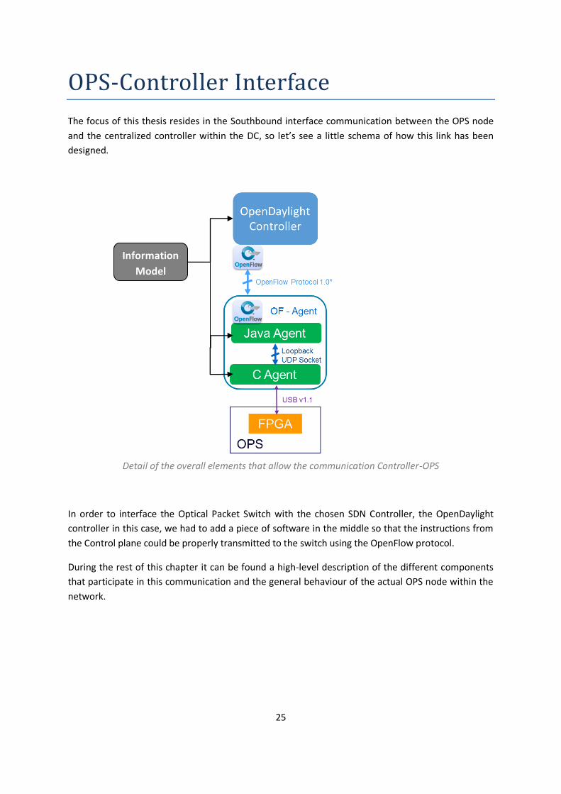
The focus of this thesis resides in the Southbound interface communication between the OPS node
and the centralized controller within the DC, so let’s see a little schema of how this link has been
designed.
Detail of the overall elements that allow the communication Controller-OPS
In order to interface the Optical Packet Switch with the chosen SDN Controller, the OpenDaylight
controller in this case, we had to add a piece of software in the middle so that the instructions from
the Control plane could be properly transmitted to the switch using the OpenFlow protocol.
During the rest of this chapter it can be found a high-level description of the different components
that participate in this communication and the general behaviour of the actual OPS node within the
network.
Information
Model
26
OPS-Controller Interface Participants
OpenDaylight Controller Developed by the OpenDaylight Project within the Linux Foundation, a community-led, open-source,
industry-supported project to advance Software Defined Networking; it is the chosen controller
framework to be used for the project by the Lightness partners.
The first and only version release of the Controller up until now, named Hydrogen, was made
publicly available on the 4th of February of 2014 and, while being still a preliminary version of the
intended goals of their project, it is already functional and supports several SDN open standards and
interfaces, including OpenFlow. This Controller can be run in any regular host PC that is able to run a
Java Virtual Machine.
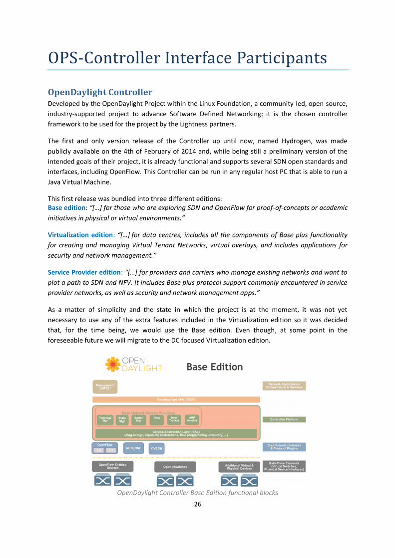
This first release was bundled into three different editions: Base edition: “[…] for those who are exploring SDN and OpenFlow for proof-of-concepts or academic
initiatives in physical or virtual environments.”
Virtualization edition: “[…] for data centres, includes all the components of Base plus functionality
for creating and managing Virtual Tenant Networks, virtual overlays, and includes applications for
security and network management.”
Service Provider edition: “[…] for providers and carriers who manage existing networks and want to
plot a path to SDN and NFV. It includes Base plus protocol support commonly encountered in service
provider networks, as well as security and network management apps.”
As a matter of simplicity and the state in which the project is at the moment, it was not yet
necessary to use any of the extra features included in the Virtualization edition so it was decided
that, for the time being, we would use the Base edition. Even though, at some point in the
foreseeable future we will migrate to the DC focused Virtualization edition.
OpenDaylight Controller Base Edition functional blocks
27
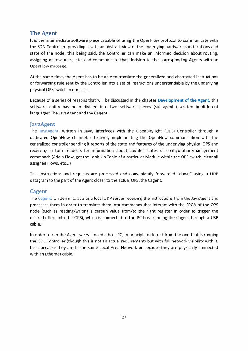
The Agent It is the intermediate software piece capable of using the OpenFlow protocol to communicate with
the SDN Controller, providing it with an abstract view of the underlying hardware specifications and
state of the node, this being said, the Controller can make an informed decision about routing,
assigning of resources, etc. and communicate that decision to the corresponding Agents with an
OpenFlow message.
At the same time, the Agent has to be able to translate the generalized and abstracted instructions
or forwarding rule sent by the Controller into a set of instructions understandable by the underlying
physical OPS switch in our case.
Because of a series of reasons that will be discussed in the chapter Development of the Agent, this
software entity has been divided into two software pieces (sub-agents) written in different
languages: The JavaAgent and the Cagent.
JavaAgent The JavaAgent, written in Java, interfaces with the OpenDaylight (ODL) Controller through a
dedicated OpenFlow channel, effectively implementing the OpenFlow communication with the
centralized controller sending it reports of the state and features of the underlying physical OPS and
receiving in turn requests for information about counter states or configuration/management
commands (Add a Flow, get the Look-Up Table of a particular Module within the OPS switch, clear all
assigned Flows, etc...).
This instructions and requests are processed and conveniently forwarded “down” using a UDP
datagram to the part of the Agent closer to the actual OPS; the Cagent.
Cagent The Cagent, written in C, acts as a local UDP server receiving the instructions from the JavaAgent and
processes them in order to translate them into commands that interact with the FPGA of the OPS
node (such as reading/writing a certain value from/to the right register in order to trigger the
desired effect into the OPS), which is connected to the PC host running the Cagent through a USB
cable.
In order to run the Agent we will need a host PC, in principle different from the one that is running
the ODL Controller (though this is not an actual requirement) but with full network visibility with it,
be it because they are in the same Local Area Network or because they are physically connected
with an Ethernet cable.

28
OPS node
Nomenclature Our Optical Packet Switch node internal design can be defined by two numbers:
W: the number of lambdas that a Module is able to manage. M: the number of Modules that comprise the OPS
Because of the way our OPS works, this means univocally that it will have a set amount of IN ports
and OUT ports, where:
This means that a particular OPS architecture following our design can be identified by the (W, M)
tuple or by the INxOUT expression.
In our case, the architecture we have been working with had 2 Modules per OPS and 2 lambdas per
Module, so it can be described as OPS(2,2) or OPS4x4.
Other examples of this nomenclature:
(W, M) INxOUT
OPS with 3 Modules and 2 lambdas each: OPS(2,3) OPS6x9
OPS with 4 Modules and 4 lambdas each: OPS(4,4) OPS16x16
Contents At any point, every OPS that follows the architecture proposed contains at least one or more
Modules. These Modules are the basic working pieces of the node.
Every Module has a single fibre connector for incoming data (Input Port) which, thanks to an AWG
demultiplexor, extracts a certain predefined amount W of wavelengths (also defined as InPorts in
the Cagent).
The number of fibre connectors for outgoing data (Output Ports) depends on the total number of
Modules that the OPS node contains. The explanation for this behaviour is easily understandable
once we see how the module performs the switching; in the next subsection we will find an image
representing the internal blocks of a particular OPS organization that illustrates this point.
Additionally, every Module has its own Look-Up Table (LUT) with a fixed maximum capacity of
LUTentries. This LUTentries, which contain the Label and the destination within the OPS of an
assigned flow, are checked at switching every packet by the FPGA.
Last but not least, we have the Flows and the Counters: we can assign a limited number of flows at
once to every Wavelength within a Module. Every flow will have associated two counters: Number
of packets received and number of packets retransmitted. The reason why the number of flows
assignable is finite is that the Bitfile, which is tasked with the control and updating of counters,
needs to know how many counters it has to manage as well as its location and triggering conditions.

29
Example Architecture: OPS 4x4 In order to discuss the logical blocks that build up our OPS and the relationships between them, we
are going to focus in one example in particular, so it is more understandable. Let’s then present the
OPS 4x4:
OPS 4x4 schematic
This OPS node contains two Modules, each of them with one input fibre and two output fibres, and
capable of switching separately packets from two different wavelengths according to their labels.
Note how the exits of the SOA are connected to the respective output fibres. This particular example
illustrates perfectly the two rules that govern/restrict the switching matrix of the OPS node:
Supposing an OPS node with M Modules, each one capable of switching W wavelengths: A packet
entering the OPS through the Module number n will be switched to the Output port number n of
one of the Modules, or dropped. This is not dependent on the actual Wavelength used. The
switching matrix is included within the Information Model.
Also, if two packets from the same Module but with different wavelength are forwarded to the same
destination there will be contention and only one of them will pass, according mainly to their
respective priorities.
Label Extractor
Label Extractor
LP
SOA sw
SOA sw
FPGA
AWG
AWG
AWG
λ1
λ2
λ1
λ2 λ2
λ1
Label Extractor
Label Extractor
LP
SOA sw
SOA sw
FPGA
AWG
AWG
AWG λ1
λ2
λ1
λ2
λ1
λ2
OPS
λ1, λ2
λ1, λ2
λ1, λ2
λ1, λ2
λ1, λ2
λ1, λ2
30
When a Packet is correctly forwarded the FPGA processing the labels sends back through a
dedicated link to the ToR originating this traffic an ACK signal acknowledging the reception, but
when this signal is not sent the packet is counted as received but not processed and the ToR
understands that has to re-send it.
The connection between the FPGA and the ToR is done through a simple rainbow cable, as it is
expected that within the Data Centre there will be direct connection between such elements, but in
any case, the actual nature of this link is out of the scope of the thesis.
Interfaces There are three interfaces that allow the overall communication ODL Controller-Agent-OPS:
OpenFlow channel The OpenFlow channel, as defined in the OpenFlow switch specification, is the secure TLS link (a
cryptographic protocol that runs over a TCP communication) that connects the Controller and the
OpenFlow Agent from a Switch, in our case, with the JavaAgent.
From the SDN point of view, this would be the Southbound Interface as anything lying below the
agent is transparent to the Controller.
Loopback UDP sockets Two different ports from the loopback interface of the host PC (IP address 127.0.0.1) are used in
order to communicate the two subparts in which the Agent has been divided; Cagent and JavaAgent.
Even though UDP is a non-reliable best-effort Internet protocol, its sheer speed and simplicity and
the fact that the messages interchanged through this interface will not go out of the host PC
(provided that the Cagent and the JavaAgent are running in the same host, as expected) completely
outweigh and annul its disadvantages, allowing the communication between a program written in C
and another one written in Java in a fast, simple and adaptable way.
The actual messages interchanged between both parts of the Agent are described in a simple and
extendable protocol created by Fernando Agraz and myself which is defined in the file OFAgent-OPS-
Spec.txt, included in the project’s code.
USB link We have to options if we want to physically connect the FPGA (and, by extension, the OPS) to the
host PC that runs the Agent in order to control it through the use of the libraries and .dll provided by
the board manufacturer: use the conventional PCI interface or the USB v1.1 port.
Even though the PCI interface would give us a better and faster performance, as seen in the
XtremeDSP kit User Guide, most modern laptops and computers don’t have PCI slots anymore or
have PCI express, which is not compatible, but have instead several USB v2.0 or v3.0 ports.
So, for the reasons mentioned above, we will refer to the link that allows the communication
between the FPGA and the Cagent part of the Agent as the USB link or interface.

31
Taking into account that a single USB Enhanced Host Controller Interface (EHCI) can manage 127
devices (counting every USB hub as a device) and the fact that hubs can be cascaded up to 7 levels
deep it is very straightforward to see which of the two interfaces is more scalable. It is also worth
noting that problems due to shortages in USB alimentation will not be an issue for our system since
the FPGA is powered with its own cord.
Information model The information model is a representation of the contents and features of our OPS switch, as well as
the relationships between those contents and/or features, which can be used by different entities of
our system (the Agent and the Controller) in order to extract some relevant information necessary to
perform their intended duties.
In our system the information model is an XML file that describes in a hierarchical manner how the
OPS is organized (number of Modules, ports and wavelengths,...), the switching matrix, nominal
optical parameters etc.
This XML file is read by the Cagent and the JavaAgent, but is worth noting that the information that
is relevant for one entity may be unimportant for the other, as they are in different levels of
abstraction.
E.g. The Cagent, which is closer to the hardware, needs to know the maximum number of LUTentries
allowed in a Module in order to manage the Look-Up Table and write/read the right registers from
the FPGA and will extract this information from the Information Model, while the JavaAgent, closer
to the Controller, will not need this low-level information.
The current, latest version of the information model can be found in the file OPS_IM_v3.xml, which
describes an OPS with two Modules that switch up to 2 different wavelengths each one.
Nevertheless the information model is expected to keep changing and being extended to meet the
requirements as long as the Lightness project keeps being developed.
Note: the difference between OPS_IM_v3.xml and older, obsolete versions of the Information Model
(such as OPS_IM_v2.xml) is not, for instance, the number of Modules that the OPS has but the way
of expressing how many Modules it contains.
32
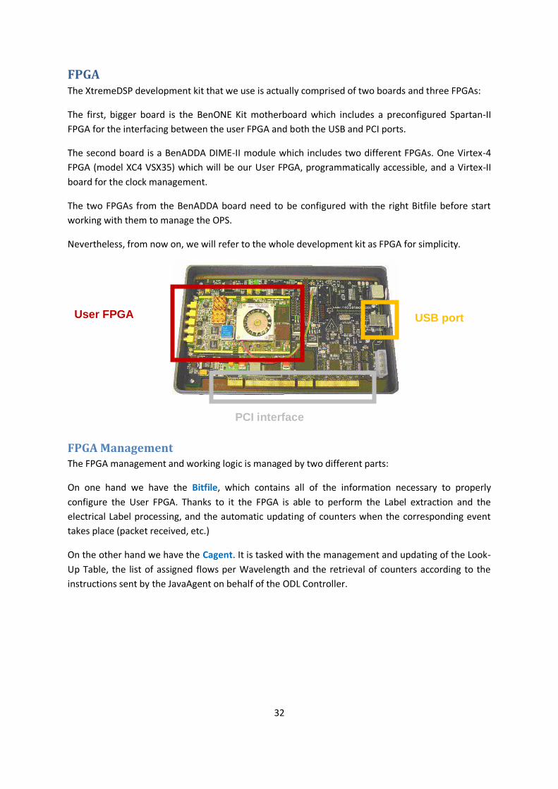
FPGA The XtremeDSP development kit that we use is actually comprised of two boards and three FPGAs:
The first, bigger board is the BenONE Kit motherboard which includes a preconfigured Spartan-II
FPGA for the interfacing between the user FPGA and both the USB and PCI ports.
The second board is a BenADDA DIME-II module which includes two different FPGAs. One Virtex-4
FPGA (model XC4 VSX35) which will be our User FPGA, programmatically accessible, and a Virtex-II
board for the clock management.
The two FPGAs from the BenADDA board need to be configured with the right Bitfile before start
working with them to manage the OPS.
Nevertheless, from now on, we will refer to the whole development kit as FPGA for simplicity.
FPGA Management The FPGA management and working logic is managed by two different parts:
On one hand we have the Bitfile, which contains all of the information necessary to properly
configure the User FPGA. Thanks to it the FPGA is able to perform the Label extraction and the
electrical Label processing, and the automatic updating of counters when the corresponding event
takes place (packet received, etc.)
On the other hand we have the Cagent. It is tasked with the management and updating of the Look-
Up Table, the list of assigned flows per Wavelength and the retrieval of counters according to the
instructions sent by the JavaAgent on behalf of the ODL Controller.
User FPGA
PCI interface
USB port
33
Programmatically controlled elements
Look-Up Table
The look-up table (LUT) is the list of entries that the Module uses to match the labels it receives and
then decide if it knows where should the corresponding packet be forwarded or not.
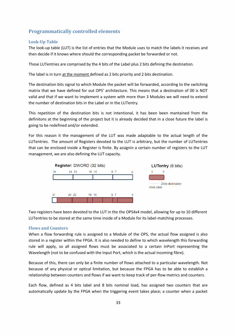
Those LUTentries are comprised by the 4 bits of the Label plus 2 bits defining the destination.
The label is in turn at the moment defined as 2 bits priority and 2 bits destination.
The destination bits signal to which Module the packet will be forwarded, according to the switching
matrix that we have defined for out OPS’ architecture. This means that a destination of 00 is NOT
valid and that if we want to implement a system with more than 3 Modules we will need to extend
the number of destination bits in the Label or in the LUTentry.
This repetition of the destination bits is not intentional, it has been been mantained from the
definitons at the beginning of the project but it is already decided that in a close future the label is
going to be redefined and/or extended.
For this reason it the management of the LUT was made adaptable to the actual length of the
LUTentries. The amount of Registers devoted to the LUT is arbitrary, but the number of LUTentries
that can be enclosed inside a Register is finite. By assignin a certain number of registers to the LUT
management, we are also defining the LUT capacity.
Two registers have been devoted to the LUT in the the OPS4x4 model, allowing for up to 10 different
LUTentries to be stored at the same time inside of a Module for its label-matching processes.
Flows and Counters
When a flow forwarding rule is assigned to a Module of the OPS, the actual flow assigned is also
stored in a register within the FPGA. It is also needed to define to which wavelength this forwarding
rule will apply, so all assigned flows must be associated to a certain InPort representing the
Wavelength (not to be confused with the Input Port, which is the actual incoming fibre).
Because of this, there can only be a finite number of flows attached to a particular wavelength. Not
because of any physical or optical limitation, but because the FPGA has to be able to establish a
relationship between counters and flows if we want to keep track of per-flow metrics and counters.
Each flow, defined as 4 bits label and 8 bits nominal load, has assigned two counters that are
automatically update by the FPGA when the triggering event takes place; a counter when a packet
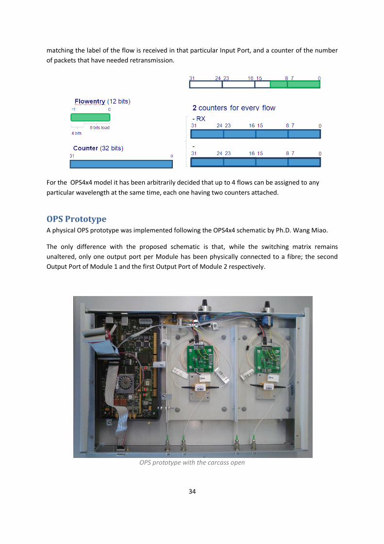
34
matching the label of the flow is received in that particular Input Port, and a counter of the number
of packets that have needed retransmission.
For the OPS4x4 model it has been arbitrarily decided that up to 4 flows can be assigned to any
particular wavelength at the same time, each one having two counters attached.
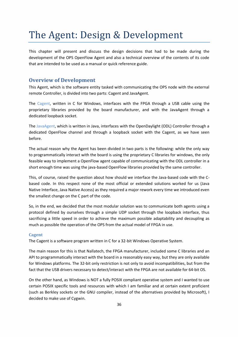
OPS Prototype A physical OPS prototype was implemented following the OPS4x4 schematic by Ph.D. Wang Miao.
The only difference with the proposed schematic is that, while the switching matrix remains
unaltered, only one output port per Module has been physically connected to a fibre; the second
Output Port of Module 1 and the first Output Port of Module 2 respectively.
OPS prototype with the carcass open

35
Development of the Agent
36
The Agent: Design & Development
This chapter will present and discuss the design decisions that had to be made during the
development of the OPS OpenFlow Agent and also a technical overview of the contents of its code
that are intended to be used as a manual or quick reference guide.
Overview of Development This Agent, which is the software entity tasked with communicating the OPS node with the external
remote Controller, is divided into two parts: Cagent and JavaAgent.
The Cagent, written in C for Windows, interfaces with the FPGA through a USB cable using the
proprietary libraries provided by the board manufacturer, and with the JavaAgent through a
dedicated loopback socket.
The JavaAgent, which is written in Java, interfaces with the OpenDaylight (ODL) Controller through a
dedicated OpenFlow channel and through a loopback socket with the Cagent, as we have seen
before.
The actual reason why the Agent has been divided in two parts is the following: while the only way
to programmatically interact with the board is using the proprietary C libraries for windows, the only
feasible way to implement a OpenFlow agent capable of communicating with the ODL controller in a
short enough time was using the java-based OpenFlow libraries provided by the same controller.
This, of course, raised the question about how should we interface the Java-based code with the C-
based code. In this respect none of the most official or extended solutions worked for us (Java
Native Interface, Java Native Access) as they required a major rework every time we introduced even
the smallest change on the C part of the code.
So, in the end, we decided that the most modular solution was to communicate both agents using a
protocol defined by ourselves through a simple UDP socket through the loopback interface, thus
sacrificing a little speed in order to achieve the maximum possible adaptability and decoupling as
much as possible the operation of the OPS from the actual model of FPGA in use.
Cagent
The Cagent is a software program written in C for a 32-bit Windows Operative System.
The main reason for this is that Nallatech, the FPGA manufacturer, included some C libraries and an
API to programmatically interact with the board in a reasonably easy way, but they are only available
for Windows platforms. The 32-bit only restriction is not only to avoid incompatibilities, but from the
fact that the USB drivers necessary to detect/interact with the FPGA are not available for 64-bit OS.
On the other hand, as Windows is NOT a fully POSIX compliant operative system and I wanted to use
certain POSIX specific tools and resources with which I am familiar and at certain extent proficient
(such as Berkley sockets or the GNU compiler, instead of the alternatives provided by Microsoft), I
decided to make use of Cygwin.
37
Cygwin is a collection of GNU and Open Source tools which provide functionality similar to a Linux
distribution on Windows through an additional emulation layer on runtime that allows substantial
yet not complete POSIX API functionality.
For the development of the code I chose NetBeans IDE with its C/C++ plugin, as I was already familiar
with it and it was very straightforward to make it work together with Cygwin, as an alternative to the
use of Microsoft Visual Studio, probably the best IDE for developing C in Windows IF you are not tied
to the constrains listed before.
JavaAgent
JavaAgent is a program written in Java and intended to be executed in a 32-bit JRE 7 environment.
Java is an Object Oriented language which could perfectly stand on its own in order to manage the
logical abstraction of the OPS from the Agent point of view, centralizing all the limited intelligence
existing on the OPS taking it away from the Cagent as much as possible. Nevertheless, the Cagent
also benefits from (and, to an extent, actually needs) some information about the state and
organization of the OPS it is interacting with.
So, finally, it was decided that both sides of the Agent would retain part of the intelligence of the
node, with Cagent knowing the structure of the Ops and keeping track of its state (flows assigned,
etc.) and the JavaAgent also knowing the structure (even if focusing in slightly different aspects of it)
so it can give to the ODL Controller an accurate abstract description of it without having to
communicate with the Cagent (as it would do to give it commands or get the state of port counters).
The “only 32-bit systems” restriction is self-imposed for the following reason: the JavaAgent is
meant to be run in the same PC host where the Cagent is running, so they are as close as possible
both logically and physically. This means that the restrictions applied to the Cagent in this respect
also apply to the Java part of the Agent.
For developing this part of the code I used NetBeans IDE again, but this time with the regular Java
development tools that come with it by default. I used the JDK version 7 instead of the newest 8
(released on 18-3-2014) because of compatibility issues that appeared with the ODL Controller,
which also runs from a Java virtual machine.

38
Agent’s Code Overview
In this section I will give a list of the contents of the code within each subpart or the Agent, giving a
high level description of its uses and functionalities, followed by an in-detail explanation of the logic
that governs how they work.
Cagent’s Code The Cagent part of the code is divided into header files, defining functions and constants, and source
files, which implement those functions. These files have been organized into groups according to
their intended global purpose.
Cagent: Code Schematic
Library Files
Related to the FPGA
dimesdl.lib vidime.lib
Header Files
Related to the FPGA Open source third party libraries
OPS/Agent management
Constants and globals
dimesdl.h vidime.h fpga_control.h switchfpga.h
ezxml.h linkedlist.h
m_parser.h ops.h udpcomm.h
filenames.h operation_code.h global.h
Source Files
Related to the FPGA Open source third party libraries
OPS/Agent management
Global
fpga_control.c switchfpga.c
ezxml.c linkedlist.c
m_parser.c ops.c udpcomm.c
main.c
Cagent: Code Overview
Related to the FPGA
dimesdl.h
Header file provided by Nallatech Ltd. that allows us to use the constants and functions needed to
interact programmatically with the FPGA.
DIME stands for DSP and Image Processing Modules for Enhanced FPGAs. DIMESDL stands for DIME Software Development Library.

39
vidime.h
Header file provided by Nallatech Ltd. that allows us to use a set of constants and functions to
programmatically read/write from/to a Virtex FPGA card compatible. This transference of data can
be done one register at a time or in bigger blocks of memory using the DMA communication.
VIDIME stands for Virtex DIME.
fpga_control.h/c
They declare and implement functions that wrap in a far more convenient and human-friendly way
the API functions provided in vidime.h and dimesdl.h for accessing, configuring the FPGA
switchfpga.h/c
They declare and implement functions that wrap in a far more convenient and human-friendly way
the API functions provided in vidime.h and dimesdl.h that allow the control and implementation of
the structures defined in ops.h to be run on top of the actual FPGA hardware.
It includes the functions to add/delete LUTentries and flows from the FPGA writing in its registers, as
well as the functions to retrieve the statistics (counters) from the FPGA.
The logic behind which registers exactly to write/read is coded in the global.h header file.
Open source third party libraries
ezxml.h/c
Open source library and implementation for parsing XML documents developed by Aaron Voisine. Source: http://ezxml.sourceforge.net/
linkedlist.h/c
Library that implements the creation and management of generic linked lists, heavily based in the file linklist.h by Kunihiro Ishiguro that was part of GNU Zebra. Source: https://www.gnu.org/software/zebra/
OPS/Agent management
m_parser.h/c
They declare and implement functions that allow us to read a xml file (using the ezxml library) with
the configuration of the OPS and load its contents into the Ops structs defined in ops.h.
Note that every time that the configuration xml files change their internal structure, m_parser.c
must be changed in order to match the new layout and be able to read it.
ops.h/c
These files contain functions that allow the creation and manipulation of the Ops and its contents as
structs. They also define some masks to help with the bit-wise manipulation of flows, labels and
Look-Up Table entries.
Among the functions implemented we can find the ones responsible of the creation/liberation of
resources as well as the addition/modification/deletion of ports, Look-Up Table entries and flows.

40
The structures defined are the following:
- OPS: Struct representation of the Optical Packet Switch. Every one of them contains a list with 1 or more modules.
- Module: Every Module contains a list of Input Ports and Output Ports and a Look-Up Table. - LUT: Look-Up Table with its Look-Up Table entries. Its capacity is limited. - InPort: Input Port of a Module, it defines its wavelength and includes a list of assigned flows. - OutPort: Output Port of a Module
udpcomm.h/c
Functions that allow the creation and manipulation of UDP sockets, as well as the functions needed
to perform the protocol communication between the Cagent and the JavaAgent, as stated in the
document OFAgent-OPS-Spec.txt
Constants and globals
filenames.h
The purpose of this header is to centralize in a single point of the software the name of the files to
be used in order to configure the system. This makes its management/change easier.
It includes:
- FPGA bitfile: ops4x4.bit - FPGA clock bitfile: osc_clock_2v80.bit
- XML file: OPS_IM_v3.xml
operation_code.h
Header containing a set of defines with the code of the messages of the communication protocol
between the Cagent and the JavaAgent, as stated in the document OFAgent-OPS-Spec.txt
global.h
This header contains several sets of defines with global values that must be known by a different
parts of the code.
It includes defines related to:
- Global management and debugging of the software
- Cagent – JavaAgent communication
- OPS organization
- Localization of registers in the FPGA
main.c
Actual source of the executable file, recreates internally the structure of the OPS node according to
the XML file definition, performs the configuration and loading of the FPGA, and starts a UDP server
to receive instructions from the JavaAgent.
Given the capital importance of both global.h and main.c, the particularities of these files will be
further discussed in the following section
41
Cagent: main.c and global.h behaviour detailed
global.h
As it has been stated before, the definitions included in this header file can be distributed into 4
categories. Let’s take a deeper look into them:
Global management and debugging of the software
DEBUGOPS On this value depends the amount of human-readable information printed in the screen related to
the configuration steps and normal working operations of the Cagent.
A value of 0 would disable all this extra (but useful) info, and a value of 1 would enable it.
LOADBITFILES This value decides whether the bitfiles must be loaded into the FPGA or not. While unusual, there
are some situations where this option could be very convenient:
The loading of both bitfiles MUST be done the first time the FGPA is powered on, let it be
automatically through the Cagent or manually using the FUSE software, but unless the FPGA is
turned off the bitfile will remain loaded.
Apart from that, the action of loading them can increase the configuration time of the Cagent up to
50 seconds, depending on the host pc in use.
A value of 0 would skip the loading of both bitfiles, and a value of 1 would enable it.
SERIALFILTERING When this value is set to 1 the Cagent will only interact with the card which serial number matches
with OPSSERIAL. If none is found, the program will terminate.
Otherwise, if its value is set to 0, the Cagent will simply open the first card detected. Please note that
this might NOT be the desired outcome, especially in a situation where more than one card is
connected to the Pc host.
Extra note: Only read if you want/need to connect more than one FPGA to the pc host.
The filtering is done comparing the OPSSERIAL value with the serial of the cards attached to a certain “locate”.
This “locate” is the handler result of calling the functions locateCard_usb(), locateCard_pci(), locateCard() or
DIME_LocateCard(…), and all of them look only into 1 interface at a time.
So, if you connect two or more FPGA through USB with the host, you have to be careful about serial filtering.
But if you have only a card connected through USB and another through PCI, as they are from different
interfaces, they will not disturb each other.
OPSSERIAL The actual values of the serial numbers belonging to the two FPGAs that were available at the time
of writing this thesis were 350096 and 352066.
42
Cagent – JavaAgent communication
CAGENTIP, CAGENTPORT This is the IP address and port which the UDP server of the Cagent will be listening waiting for
commands from the JavaAgent.
There is no need of defining the address or port of the JavaAgent here as the Cagent will
automatically answer a petition into the same address that generated it.
As both JavaAgent and Cagent are expected to be running in the same host PC the IP address is set
to loopback (127.0.0.1), and port number is 12346
OPS organization
Note: The following values have been set according to what has been defined in bitfile ops4x4.bit
and the XML file OPS_IM_v3.xml.
FLOWbits Its value has been set to 12, (4bits label + 8bits load).
LOADbits Its value has been set to 8, by design.
LABELbits Its value has been set to 4, (2bits Priority + 2bits destination)
DESTbits, PRIORbits Their values have been set to 2, by design.
LUTENTRYbits Its value has been set to 6, (4bits label + 2bits destination)
LUTENTRIESINROW Its value has been set to 5. That is the number of LUTentries (6 bits) that can be stored at the same
time in a single register (32 bits).
COUNTERSPERFLOW Its value has been set to 2, Counters for received packets and counters for retransmitted packets.
Localization of registers in the FPGA
Note: The following values have been set according to what has been defined in bitfile ops4x4.bit.
The following definitions only store the position of the first register of every block of registers, not
the amount of registers in that block. In order to read an explanation of the logic behind these
numbers, please refer to section FPGA Organization.
REGLUTSTART Its value has been set to 4. There are 2 registers per Module devoted to the LUT.
REGFLOWSTART Its value has been set to 10. There are 8 registers per Module devoted to Flows.

43
REGCOUNTERSTART Its value has been set to 20. There are 16 registers per Module devoted to counters.
REGOFFSET This is the localization difference between a particular register in module "n" and the same logical
resource in module "n+1" .
Its value has been set to 100, so that the start of the LUT registers in module 1 and 2 would be in
registers number 4 and 104 respectively.
COUNTERSDMA Even though the DMA communication has not been implemented in the bitfile, neither it is being
used in the Cagent as for today, I have defined some functions that will allow its use to collect the
counters, and they required to select which DMA channel was to be used.
Its value is set to 1.
Main.c
This file controls and manages the configuration and set-up of the FPGA for the OPS, as well as
working as a bridge between the JavaAgent, who receives orders from the Controller, and the FPGA.
The main program performs the following actions in this particular order, keeping track of the time
spent in every one and providing the user with information and updates about the sub-steps within
every step (unless the constant DEBUGOPS is set to 0 in global.h):
Process command line arguments
Reads the command line arguments to see if the executable has been called adequately and, in case
that 1 extra argument has been found and it reads “-verbose”, it will activate some extra
functionalities in the main loop operation.
Load XML file and create OPS structure
Loads the XML configuration file and creates an Ops structure correctly filled according to it. It will
print the OPS state at the end, even if there are no LUTentries or flows assigned so the user can
verify that the OPS loaded is the one intended.
Open Communication with the FPGA
First of all, it locates all possible cards connected through the USB interface. Afterwards, its
behaviour may change according to some of the definitions found in the global.h header, but
supposing that both SERIALFILTERING and LOADBITFILES are set to 1, it will open a communication
the FPGA whose serial number matches de OPSSERIAL definition and load the clock and user Bitfiles
in it. At last, it will create a handler that allows the rest of the program to easily read/write registers
programmatically.
Open UDP communication with the Java
In this step a UDP server socket will be created and bounded to the loopback IP to the port defined
by the CAGENTPORT constant, waiting for messages from the JavaAgent.
44
Normal operation loop
Up until this point we have only had configuration steps, and it is not until here when the Cagent is
ready to do some real work:
First it will wait until the reception of a message (which structure and contents are defined in the
OFAgent-OPS-Spec.txt document) from the JavaAgent. Secondly, after processing the message
according to its operation number, it will prepare and send back a suitable answer. At the end, if
during the command line processing it has been determined that the option “-verbose” is activated,
the current state of the OPS will be printed in the command line interface.
The main operation loop will repeat these three steps indefinitely unless the JavaAgent sends a
CLOSE message, the cagentops.exe process is terminated manually by the user or a malformed
message is received from the JavaAgent.
Note that sending a malformed message up to the JavaAgent or any problem during the sending of
answers through the loopback interface will not terminate the loop and the program’s execution.
Closing routine
These last lines of code are tasked with closing the UPD socket, freeing all resources devoted to the
OPS struct and closing the handlers used to access/locate the FPGA before actually ending the
program’s execution.
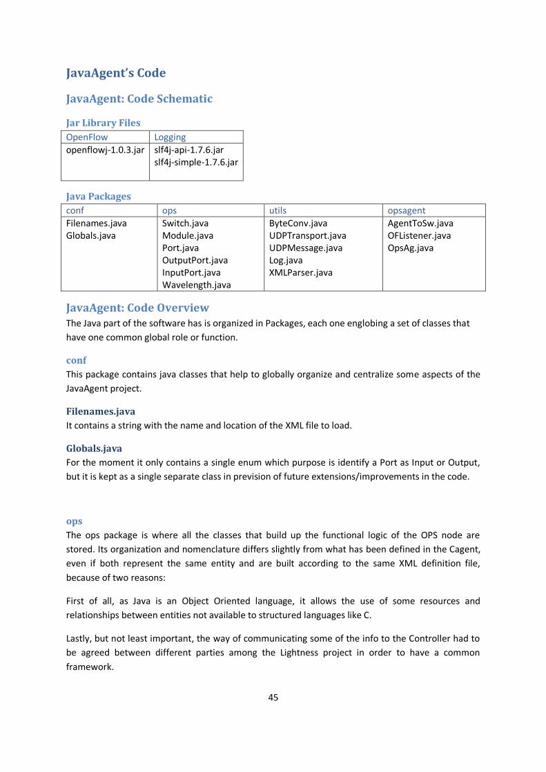
45
JavaAgent’s Code
JavaAgent: Code Schematic
Jar Library Files
OpenFlow Logging
openflowj-1.0.3.jar slf4j-api-1.7.6.jar slf4j-simple-1.7.6.jar
Java Packages
conf ops utils opsagent
Filenames.java Globals.java
Switch.java Module.java Port.java OutputPort.java InputPort.java Wavelength.java
ByteConv.java UDPTransport.java UDPMessage.java Log.java XMLParser.java
AgentToSw.java OFListener.java OpsAg.java
JavaAgent: Code Overview The Java part of the software has is organized in Packages, each one englobing a set of classes that
have one common global role or function.
conf
This package contains java classes that help to globally organize and centralize some aspects of the
JavaAgent project.
Filenames.java
It contains a string with the name and location of the XML file to load.
Globals.java
For the moment it only contains a single enum which purpose is identify a Port as Input or Output,
but it is kept as a single separate class in prevision of future extensions/improvements in the code.
ops
The ops package is where all the classes that build up the functional logic of the OPS node are
stored. Its organization and nomenclature differs slightly from what has been defined in the Cagent,
even if both represent the same entity and are built according to the same XML definition file,
because of two reasons:
First of all, as Java is an Object Oriented language, it allows the use of some resources and
relationships between entities not available to structured languages like C.
Lastly, but not least important, the way of communicating some of the info to the Controller had to
be agreed between different parties among the Lightness project in order to have a common
framework.
46
Keeping this in mind, the classes defined in this package are:
Switch.java
The representations of the Ops node, its attributes are its id and a list of modules.
Module.java
This class represents an Ops´ module, including its id, a list of Input Ports, a list of Output Ports and a
link to the Switch it belongs to.
Port.java
Here we can find the common basic attributes and methods of a Port, which will be inherited by
both Input and Output ports.
OutputPort.java
Every Output Port represents the fibre where outgoing traffic is forwarded.
InputPort.java
Every Input Port represents the input fibre where the incoming is received. Even if the Module class
allows us to have a list of Input Ports, with the current working structure of the OPS, we will only
have 1 at a time.
Wavelength.java
The Wavelengths represent the different lambdas that are transported within the fibre, reaching the
InputPort and are processed by the Module. A list of them is included in the InputPort.
Note that a combination of InputPort and Wavelengths is what, in the Cagent, is defined as InPort.
utils
Within this package we can find a series of auxiliary classes and methods that help dealing different
aspects of the code and functionalities of the JavaAgent. Almost all of them were either written or
adapted from a third party library by UPC’s researcher Fernando Agraz.
ByteConv.java
Here we can find methods implementing some of the most useful and necessary byte conversions
between elements, such as a method that extracts a certain number of bytes from a byte array and
returns its joint value as an integer or another one that does exactly the opposite.
UDPTransport.java
This class implements some methods that allow the creation of a UPD socket and the
transmission/reception of an UDPMessage through it.
UDPMessage.java
This wrapper class defines a UDP packet in such a way that can be used in combination with the
previously mentioned UDPTransport.java.
Log.java
This log creation/manipulation class is required by UDPTransport.java, even if it is not actively used.

47
XMLParser.java
It Implements the methods that read XML files through a SAX parser (Simple API for XML parsing)
and, according to the contents of a matching version of our XML configuration file, return a fully
populated Switch instance representing the Ops node.
This is the only class from this package which was fully developed by me.
opsagent
AgentToSw.java
The implementation of the communication protocol between the Cagent and the JavaAgent, from
the last one’s side, can be found here. AgentToSw.java functionality for the JavaAgent actually
mirrors the one that udpcomm.h/c adds to the Cagent.
OFListener.java
This class implements the OpenFlow communication between the JavaAgent and the ODL Controller.
This file is heavily based in the OFListener java class is part of (and can be found within) the
OpenDaylight controller.
Given its importance and complexity, in the next section it will be further explained the way it works.
OpsAg.java
OpsAg.java is the main class of the JavaAgent. It calls the necessary methods from elsewhere of this code in order to read the XML file and start the communications with both the Cagent and the ODL Controller. Its functionality and capabilities will be further discussed in the next section.
JavaAgent: OFListener.java and OpsAg.java behaviour detailed
OFListener.java
This class functionality is double: On one hand it will start a thread that acts as a listener of the
OpenFlow channel, waiting for events (OpenFlow messages from the Controller) and reacting to
them according to its programming. On the other hand, some of the OpenFlow messages received
will command the JavaAgent to interact with the OPS through the Cagent, thus calling methods from
the AgentToSw.java class.
At the moment of writing this thesis the OFListener.java does not fully comply with the OpenFlow
standard as it is not capable of processing all the OpenFlow messages defined in it. The messages to
which this class is capable of reacting correctly are:
- HELLO, to start the communication with the ODL controller through the OpenFlow protocol. - ECHO_REPLY, among other things, it allows the ODL to check if the communication link is
still working. - GET_CONFIG_REQUEST, not used by the moment, but would allow the controller to
set/unset some protocol and control flags for the JavaAgent. - FEATURES_REQUEST, only for port counters, not for flow counters.

48
- FLOW_MOD, for adding and deleting a flow (modifying a flow is understood as deleting the old and adding the new one).
- BARRIER_REQUEST, for the management of several OpenFlow messages as an ordered batch. More information about this point can be found in the OpenFlow protocol documentation.
- STATS_REQUEST, only for port counters, not for flow counters at the moment.
OpsAg.java
This file controls and manages the configuration and set-up of the JavaAgent, as well as its links and
connections “up” towards the Controller and “down” to the Cagent. The executable
JavaAgentOPS.jar will be created from this class.
When we execute this file the following steps will be performed:
Process command line arguments
In this step the OpsAg reads the command line arguments to see if extra options have been included
in the call. These options, which are defined within the method parseArgs(...) can be:
- -h or --help: it prints help about the available options and their usage, ending the program’s
execution afterwards.
- -ip or --setip: it allows the user to decide in execution time the IP address of the ODL
controller to which the JavaAgent will be connected. If this option is not set, the JavaAgent
will use a default address: 127.0.0.1, as if the ODL controller were physically located in the
same host pc as itself.
- -p or --port: the number written after this option will be the port where the JavaAgent will
be listening for messages from the ODL Controller. If this option is not set, the JavaAgent
will use the default port: 6633.
Read XML file
Here, using the XMLParser.java class it will read the XML configuration file and create a filled Switch
instance object according to it and print it on the screen.
Establish connection with the ODL Controller
At this point the JavaAgent will create a stream-oriented socket (the type needed for TCP or TLS
communications, for instance) and connect it to the OpenDaylight Controller.
Start OFListener thread
Finally, the OpsAg will end configuring itself (creating a couple of objects that are included among its
attributes and are necessary for the OFListener) and create an instance of OFListener and start its
execution as a thread. From this moment on the OpsAg will not do anything else, depending
completely on the Listener thread to react to events and performs its duties as OpenFlow Agent.

49
Validation of the Agent

50
Guide to Run the Agent
This chapter will present the technical requirements that have to be met in order to run the Agent
and also present a step by step guide about how to use it.
At the end I have included some of the scenarios that were used to experimentally test and validate
the tool developed.
Requirements: Software, hardware and files needed in the same place where the executables are:
Cagent
EXECUTABLES cagentops.exe
LIBRARY FILES cygwin1.dll
BITFILES
ops4x4.bit osc_clock_2v80.bit
CONFIG FILES OPS_IM_v3.xml
SOFTWARE INSTALLED Nallatech’s FUSE System Software
HARDWARE XtremeDSP development kit-IV board USB v1.1 compatible cable
JavaAgent
EXECUTABLES JavaAgentOPS.jar
LIBRARY FILES (inside folder lib)
openflowj-1.0.3 slf4j-api-1.7.6 slf4j-simple-1.7.6
CONFIG FILES OPS_IM_v3.xml
SOFTWARE INSTALLED Java JDK v1.7.0_u55 for Windows 32-bit
Agent’s requirements detailed
Cagent
For the C executable (.exe) of this software to run in a computer over a Windows 32-bit OS we need:
Hardware
- XtremeDSP development kit-IV board (a Virtex-4 FPGA) including its power supply cable.
- USB v1.1 compatible cable (OR PCI cable to connect the board to the computer).
Software
- Nallatech’s FUSE System Software
Included with XtremeDSP development kit-IV, this software provides and installs all the
necessary .dll to the system and also installs the USB drivers required to be able to interact with
the FPGA through that channel. It requires up to 80 MB of Hard disk space.
51
Files
The following files must be included in the same folder where the compiled executable is located.
Library Files:
- cygwin1.dll
This dynamically linked library is needed to provide Cygwin’s extra capabilities, especially for pc
hosts that do not have Cygwin installed.
Configuration files:
- OPS_IM_v3.xml
It is used to load the configuration of the physical OPS node into the control software. Its
hierarchically structured content has been designed to effectively map the main physical and
logical capabilities of the OPS, and its content can be modularly rewritten if said capabilities
change.
Bitfiles:
Developed with Xilinx ISE, they are used to configure the FPGA and/or its internal clock.
- osc_clock_2v80.bit
We need it for configuring the internal clock for the FPGA, provided by Nallatech Ltd. with the
XtremeDSP development kit-IV.
- ops4x4.bit
This bitfile must be made on purpose and part of its content (number of modules, number of
input/output channels, register allocation) must be consequently reflected in the .xml
configuration files and/or the global constants defined within the code of the Cagent, while
others (pin connection, counters update logic, …), although important and necessary, are not
taken into account by the Cagent as it is transparent to them.
As I personally lacked the knowledge and expertise to actually create this file, it was PhD.
candidate Miao Wang from TU/e who developed it for the project.
JavaAgent
For the Java executable (.jar) of this software to run we need:
Software
- 32-bit Java JRE v1.7u55
Files
The following files must be included in the same folder where the .jar is going to be run.
Configuration files:
- OPS_IM_v3.xml
The xml file must be exactly the same (or at least a copy) as the one used in the Cagent part.
52
Library Files:
These three jar libraries must be stored inside a folder named “lib”.
- openflowj-1.0.3.jar
It contains the OpenFlow protocol 1.0.3 implementation written in Java. It was developed by
the Stanford University and distributed within the OpenDaylight Controller.
- slf4j-api-1.7.6.jar
- slf4j-simple-1.7.6.jar
The Simple Logging Facade for Java (SLF4J) serves as a simple facade or abstraction for
various logging frameworks (e.g. java.util.logging) allowing the end user to plug in the
desired logging framework at deployment time. In our case both files are needed for the
communication between the JavaAgent and the Controller.
More info about it can be found at http://www.slf4j.org/.
Note: It is not possible to run the Cagent in a LINUX environment without using a Windows VM,
while the JavaAgent can be run in any computer that has the right version of JRE installed.
Requirements for OpenDaylight Controller There are only two things needed for the ODL Controller to run if we use the pre-built zip file:
Software
- Java JDK v1.7u45, v1.7u45 or v1.7u55
Note that here we need the JDK, not just the JRE. Java versions other than them (such as
v1.7u25 or v1.8) will show some issues or not work at all. The decision to use a 32-bit or a 64-bit
version will depend on the host Pc where the ODL will be run.
In our case we have selected a 32-bit Java JDK v1.7u55.
Configuration Settings
- Setting the JAVA_HOME environment variable
Once a suiting Java Development kit is installed, it is really important to set the JAVA_HOME
environment variable following the steps stated below, for a 32-bit Windows OS:
1) Go to Computer->System Properties -> Advanced system settings.
2) In the "Advanced" tag click on Environment Variables
3) In System variables, check if JAVA_HOME exists. Otherwise create it.
4) Check that its value is: C:/Program Files/Java/jdk1.7.0_55
5) In System variables, check that the variables path or PATH (they are the same) include the
following value: %JAVA_HOME%\bin
NOTE: There are a lot of values together inside of the PATH variable, all separated by “;”
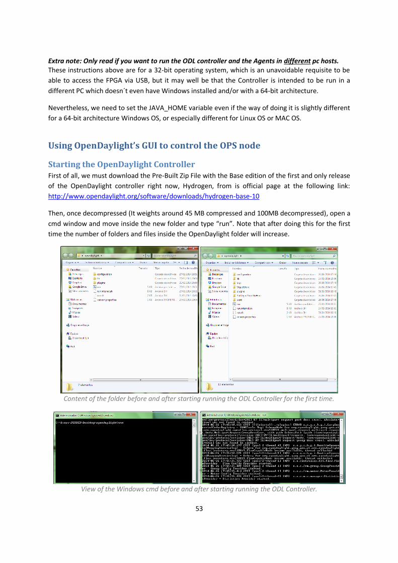
53
Extra note: Only read if you want to run the ODL controller and the Agents in different pc hosts. These instructions above are for a 32-bit operating system, which is an unavoidable requisite to be
able to access the FPGA via USB, but it may well be that the Controller is intended to be run in a
different PC which doesn´t even have Windows installed and/or with a 64-bit architecture.
Nevertheless, we need to set the JAVA_HOME variable even if the way of doing it is slightly different
for a 64-bit architecture Windows OS, or especially different for Linux OS or MAC OS.
Using OpenDaylight’s GUI to control the OPS node
Starting the OpenDaylight Controller First of all, we must download the Pre-Built Zip File with the Base edition of the first and only release
of the OpenDaylight controller right now, Hydrogen, from is official page at the following link:
http://www.opendaylight.org/software/downloads/hydrogen-base-10
Then, once decompressed (It weights around 45 MB compressed and 100MB decompressed), open a
cmd window and move inside the new folder and type “run”. Note that after doing this for the first
time the number of folders and files inside the OpenDaylight folder will increase.
Content of the folder before and after starting running the ODL Controller for the first time.
View of the Windows cmd before and after starting running the ODL Controller.
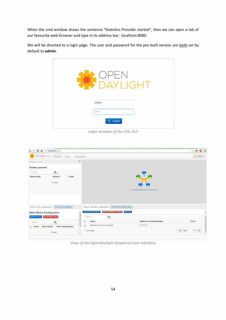
54
When the cmd window shows the sentence “Statistics Provider started”, then we can open a tab of
our favourite web browser and type in its address bar: localhost:8080
We will be directed to a login page. The user and password for the pre-built version are both set by
default to admin.
Login window of the ODL GUI
View of the OpenDaylight Graphical User Interface
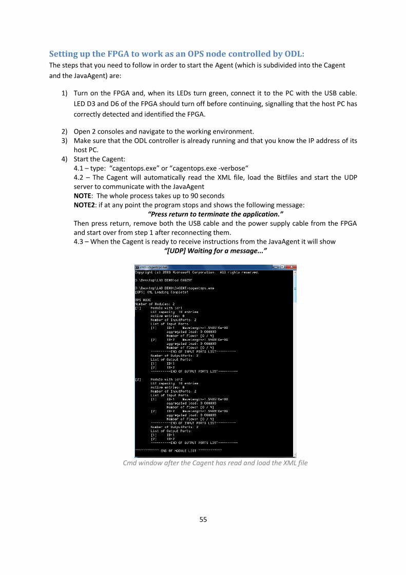
55
Setting up the FPGA to work as an OPS node controlled by ODL: The steps that you need to follow in order to start the Agent (which is subdivided into the Cagent
and the JavaAgent) are:
1) Turn on the FPGA and, when its LEDs turn green, connect it to the PC with the USB cable.
LED D3 and D6 of the FPGA should turn off before continuing, signalling that the host PC has
correctly detected and identified the FPGA.
2) Open 2 consoles and navigate to the working environment. 3) Make sure that the ODL controller is already running and that you know the IP address of its
host PC. 4) Start the Cagent:
4.1 – type: “cagentops.exe” or “cagentops.exe -verbose“ 4.2 – The Cagent will automatically read the XML file, load the Bitfiles and start the UDP server to communicate with the JavaAgent NOTE: The whole process takes up to 90 seconds NOTE2: if at any point the program stops and shows the following message:
“Press return to terminate the application.” Then press return, remove both the USB cable and the power supply cable from the FPGA and start over from step 1 after reconnecting them. 4.3 – When the Cagent is ready to receive instructions from the JavaAgent it will show
“[UDP] Waiting for a message...”
Cmd window after the Cagent has read and load the XML file
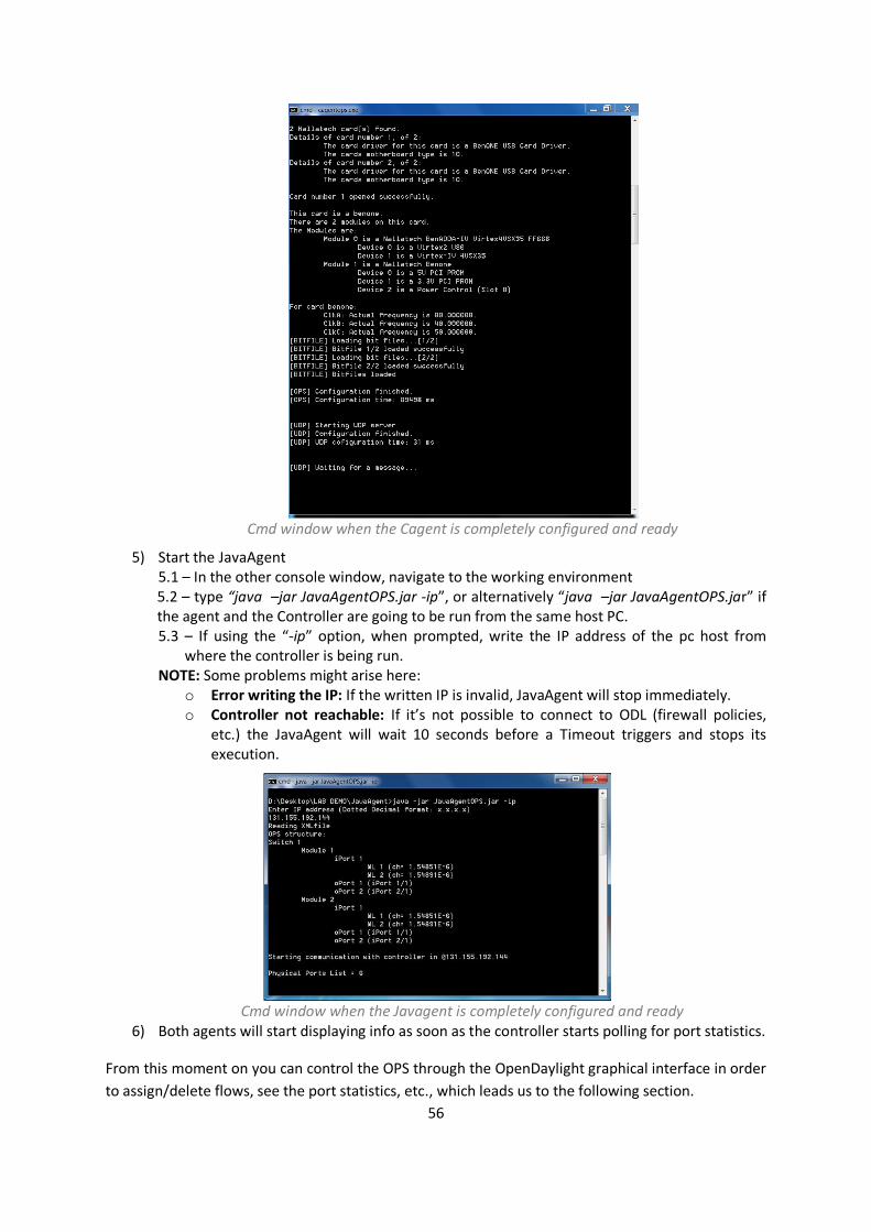
56
Cmd window when the Cagent is completely configured and ready
5) Start the JavaAgent 5.1 – In the other console window, navigate to the working environment 5.2 – type “java –jar JavaAgentOPS.jar -ip”, or alternatively “java –jar JavaAgentOPS.jar” if the agent and the Controller are going to be run from the same host PC. 5.3 – If using the “-ip” option, when prompted, write the IP address of the pc host from
where the controller is being run. NOTE: Some problems might arise here:
o Error writing the IP: If the written IP is invalid, JavaAgent will stop immediately. o Controller not reachable: If it’s not possible to connect to ODL (firewall policies,
etc.) the JavaAgent will wait 10 seconds before a Timeout triggers and stops its execution.
Cmd window when the Javagent is completely configured and ready
6) Both agents will start displaying info as soon as the controller starts polling for port statistics.
From this moment on you can control the OPS through the OpenDaylight graphical interface in order
to assign/delete flows, see the port statistics, etc., which leads us to the following section.
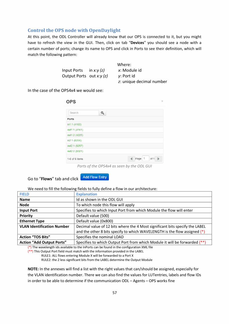
57
Control the OPS node with OpenDaylight At this point, the ODL Controller will already know that our OPS is connected to it, but you might
have to refresh the view in the GUI. Then, click on tab “Devices” you should see a node with a
certain number of ports; change its name to OPS and click in Ports to see their definition, which will
match the following pattern:
Input Ports in x:y (z) Output Ports out x:y (z)
Where: x: Module id y: Port id z: unique decimal number
In the case of the OPS4x4 we would see:
Ports of the OPS4x4 as seen by the ODL GUI
Go to “Flows” tab and click
We need to fill the following fields to fully define a flow in our architecture:
FIELD Explanation
Name Id as shown in the ODL GUI
Node To which node this flow will apply
Input Port Specifies to which Input Port from which Module the flow will enter
Priority Default value (500)
Ethernet Type Default value (0x800)
VLAN Identification Number Decimal value of 12 bits where the 4 Most significant bits specify the LABEL and the other 8 bits specify to which WAVELENGTH is the flow assigned (*)
Action “TOS Bits” Specifies the nominal LOAD
Action “Add Output Ports” Specifies to which Output Port from which Module it will be forwarded (**) (*) The wavelength ids available to the InPorts can be found in the configuration XML file (**) This Output Port field must match with the information provided in the LABEL RULE1: ALL flows entering Module X will be forwarded to a Port X RULE2: the 2 less significant bits from the LABEL determine the Output Module
NOTE: In the annexes will find a list with the right values that can/should be assigned, especially for
the VLAN identification number. There we can also find the values for LUTentries, labels and flow IDs
in order to be able to determine if the communication ODL – Agents – OPS works fine

58
As an example, let’s define a flow called Flow14 that enters the OPS4x4 through the Input Port of
Module 1 with lambda 1 and is meant to be switched to Module 2 Output port 1:
FIELD Value
Name Flow14
Node OPS
Input Port in1:1 (4160)
Priority 500
Ethernet Type 0x800
VLAN Identification Number 3585
Action “TOS Bits” 50
Action “Add Output Ports” out2:1 (8257)
Two images of the Add Flow interactive pop-up window as shown in the ODL GUI
Once a flow is defined, in the Flow Overview window we can Install Flow/Uninstall Flow.
Detail of the Flow Overview tab when a flow has been selected
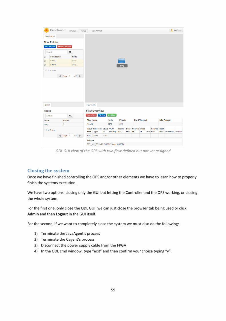
59
ODL GUI view of the OPS with two flow defined but not yet assigned
Closing the system Once we have finished controlling the OPS and/or other elements we have to learn how to properly
finish the systems execution.
We have two options: closing only the GUI but letting the Controller and the OPS working, or closing
the whole system.
For the first one, only close the ODL GUI, we can just close the browser tab being used or click
Admin and then Logout in the GUI itself.
For the second, if we want to completely close the system we must also do the following:
1) Terminate the JavaAgent’s process
2) Terminate the Cagent’s process
3) Disconnect the power supply cable from the FPGA
4) In the ODL cmd window, type “exit” and then confirm your choice typing “y”.
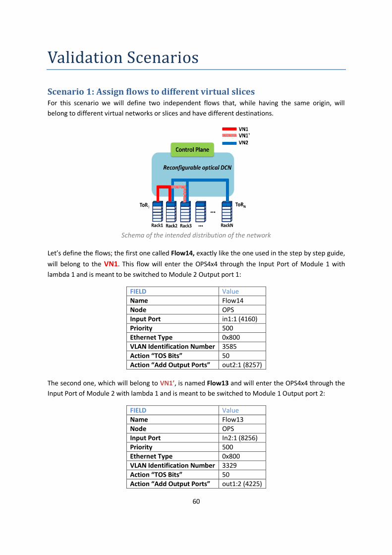
60
Validation Scenarios
Scenario 1: Assign flows to different virtual slices For this scenario we will define two independent flows that, while having the same origin, will
belong to different virtual networks or slices and have different destinations.
Schema of the intended distribution of the network
Let’s define the flows; the first one called Flow14, exactly like the one used in the step by step guide,
will belong to the VN1. This flow will enter the OPS4x4 through the Input Port of Module 1 with
lambda 1 and is meant to be switched to Module 2 Output port 1:
FIELD Value
Name Flow14
Node OPS
Input Port in1:1 (4160)
Priority 500
Ethernet Type 0x800
VLAN Identification Number 3585
Action “TOS Bits” 50
Action “Add Output Ports” out2:1 (8257)
The second one, which will belong to VN1’, is named Flow13 and will enter the OPS4x4 through the
Input Port of Module 2 with lambda 1 and is meant to be switched to Module 1 Output port 2:
FIELD Value
Name Flow13
Node OPS
Input Port In2:1 (8256)
Priority 500
Ethernet Type 0x800
VLAN Identification Number 3329
Action “TOS Bits” 50
Action “Add Output Ports” out1:2 (4225)
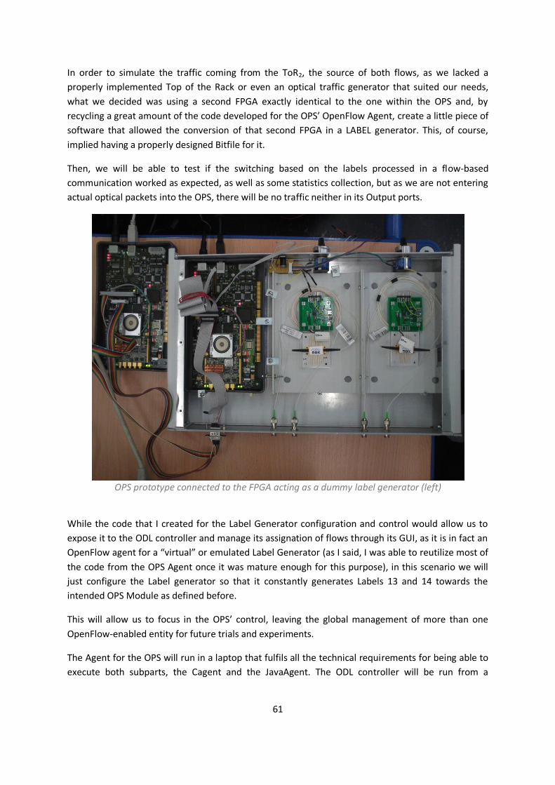
61
In order to simulate the traffic coming from the ToR2, the source of both flows, as we lacked a
properly implemented Top of the Rack or even an optical traffic generator that suited our needs,
what we decided was using a second FPGA exactly identical to the one within the OPS and, by
recycling a great amount of the code developed for the OPS’ OpenFlow Agent, create a little piece of
software that allowed the conversion of that second FPGA in a LABEL generator. This, of course,
implied having a properly designed Bitfile for it.
Then, we will be able to test if the switching based on the labels processed in a flow-based
communication worked as expected, as well as some statistics collection, but as we are not entering
actual optical packets into the OPS, there will be no traffic neither in its Output ports.
OPS prototype connected to the FPGA acting as a dummy label generator (left)
While the code that I created for the Label Generator configuration and control would allow us to
expose it to the ODL controller and manage its assignation of flows through its GUI, as it is in fact an
OpenFlow agent for a “virtual” or emulated Label Generator (as I said, I was able to reutilize most of
the code from the OPS Agent once it was mature enough for this purpose), in this scenario we will
just configure the Label generator so that it constantly generates Labels 13 and 14 towards the
intended OPS Module as defined before.
This will allow us to focus in the OPS’ control, leaving the global management of more than one
OpenFlow-enabled entity for future trials and experiments.
The Agent for the OPS will run in a laptop that fulfils all the technical requirements for being able to
execute both subparts, the Cagent and the JavaAgent. The ODL controller will be run from a
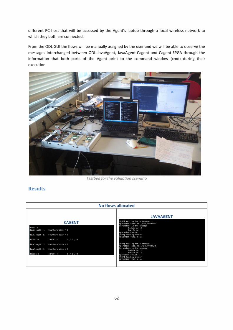
62
different PC host that will be accessed by the Agent’s laptop through a local wireless network to
which they both are connected.
From the ODL GUI the flows will be manually assigned by the user and we will be able to observe the
messages interchanged between ODL-JavaAgent, JavaAgent-Cagent and Cagent-FPGA through the
information that both parts of the Agent print to the command window (cmd) during their
execution.
Testbed for the validation scenario
Results
No flows allocated
CAGENT
JAVAAGENT
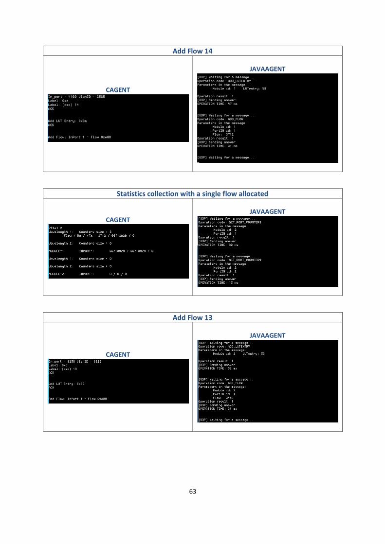
63
Add Flow 14
CAGENT
JAVAAGENT
Statistics collection with a single flow allocated
CAGENT
JAVAAGENT
Add Flow 13
CAGENT
JAVAAGENT

64
Statistics collection with both flows allocated
CAGENT
JAVAAGENT
Delete Flow 13
CAGENT
JAVAAGENT
Delete Flow 14
CAGENT
JAVAAGENT

65
ODL GUI view of the OPS
With the screenshots provided and the contents of Annex A it can be checked how the Agent
performs its intended task without fault and thus the implemented OpenFlow communication is
validated.
Note that we have only tested a subset of the implemented OpenFlow messages, which in turn I just
a fraction of all the messages that the agent has to be able to manage in order to fully implement
the OpenFlow Protocol.
66
Scenario 2: Virtual management of several OPS nodes In order to develop more advanced scenarios we need to be able to deploy more OPS nodes at the
same time.
For instance, for the time being we are limited to 2 FPGA, which allow us to deploy exactly 2 OPS
nodes using the OPS4x4 configuration further explained previously. There are two ways of increasing
this number, either obtaining more FPGAs or configuring them so that more than OPSs to share a
single FPGA device.
Both approaches present different problems: The first one implies an economical cost that is not
needed and it’s not what one could call scalable solution. The second one would suppose developing
the Bitfiles that allow such a sharing scheme, which is very time consuming and also supposes a loss
in performance (a FPGA processes the requests from the Agent in a sequential way, so if two or
more Agents send instructions to the same FPGA at the same time they will not be processed in
parallel, increasing the end-to-end latency of the configuration processes in a inadmissible way).
Either way, while we lack the proper physical equipment to perform more advanced tests at the
moment, what we could ensure is that our tool is capable of being instantiated several times. That is,
a single pc host must be able to run several Agents and thus, several OPS nodes in a seamless way
without mutual interference of any kind.
In order to test that, I will 4 JavaAgents at once from the same host, PC but not their corresponding
Cagents, to see the ODL point of view of the network.
When a JavaAgent runs without its matching Cagent it simply finds that all their messages through
the loopback socket are not answered, resulting in timeouts. As the JavaAgent does not have access
to the FPGA itself what we are actually doing is running an abstraction of the OPS that is capable of
advertising its features to the Controller according to the Information Model loaded, and nothing
else.
We must make sure that two parameters, which were irrelevant for a single running Agent, are now
properly defined:
Every Agent must assign to its OPS a unique DatapathId, which univocally identifies the switch from
the ODL point of view when it asks the Agent for its Switch’s features.
For the eventual case when the corresponding Cagents will be running together with the JavaAgents,
a different port from the loopback interface must be used for every pair so that it can be assured
that the communication works properly without interferences.

67
Results
ODL GUI view of several “virtual” OPS switches
It is then demonstrated that, once solved the hardware scalability limitations, the Agent can be used
to interface with the Controller as many OPS nodes as the pc host can support or the ODL controller
can actually manage.
It is worth noting though that even if the OpenDaylight controller can control hundreds of switches
at once, trying to do it through the GUI severely lowers that number due to the impracticability of
the graphical menus when there are too many options and the general stuttering suffered.

68
Future Work & Conclusions

69
Further Developing the Agent
Requirements for further developing the code If we want to modify the code and/or recompile the Cagent and the JavaAgent in a Windows OS and
for a Windows OS, we will need the following:
Cagent
Software
- Java SE Development Kit (JDK) v1.7u55 or later.
JRE is the minimum requirement if only the C/C++ bundled version of NetBeans is going to be
used. Any other version of NetBeans in which the C/C++ plugin is included manually by the user
will need the JDK. It takes up to 400 MB of Hard Disk space once installed.
- NetBeans IDE with the C/C++ plugin
The version 7.4 and 8 of this development software can be downloaded as a bundle and the
installer weights 62 MB. Once installed the program takes approximately 200 MB of Hard Disk
space.
- Cygwin compilers and tools
We have already discussed the benefits and functionalities that are added to the project by
using Cygwin in Section “Development: the Agent”.
For an easy way to install this software together, please refer to the next website, where you will
be able to find detailed instructions and the necessary links for the download:
https://netbeans.org/community/releases/80/cpp-setup-instructions.html
Files
Library Files:
- vidime.lib and dimesdl.lib
Both matching headers are already included within the code, but the windows library files
(provided by Xilinx with the XtremeDSP development kit-IV) must be linked to the project.
JavaAgent
Software
- Java SE Development Kit (JDK) v1.7u55 or later.
- NetBeans IDE
This time we need the Standard Edition, without the C/C++ plugin. Mind that you can have
several versions of the NetBeans IDE installed at once, so you can install NetBeans IDE 7.4 +
C/C++ plugin for the Cagent and NetBeans IDE 8 for the JavaAgent without any kind of problem.
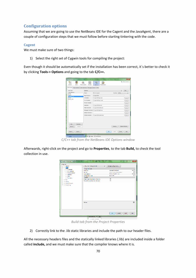
70
Configuration options Assuming that we are going to use the NetBeans IDE for the Cagent and the JavaAgent, there are a
couple of configuration steps that we must follow before starting tinkering with the code.
Cagent
We must make sure of two things:
1) Select the right set of Cygwin tools for compiling the project:
Even though it should be automatically set if the installation has been correct, it´s better to check it
by clicking Tools-> Options and going to the tab C/C++.
C/C++ tab from the NetBeans IDE Options window
Afterwards, right-click on the project and go to Properties, to the tab Build, to check the tool
collection in use.
Build tab from the Project Properties
2) Correctly link to the .lib static libraries and include the path to our header files.
All the necessary headers files and the statically linked libraries (.lib) are included inside a folder
called include, and we must make sure that the compiler knows where it is.
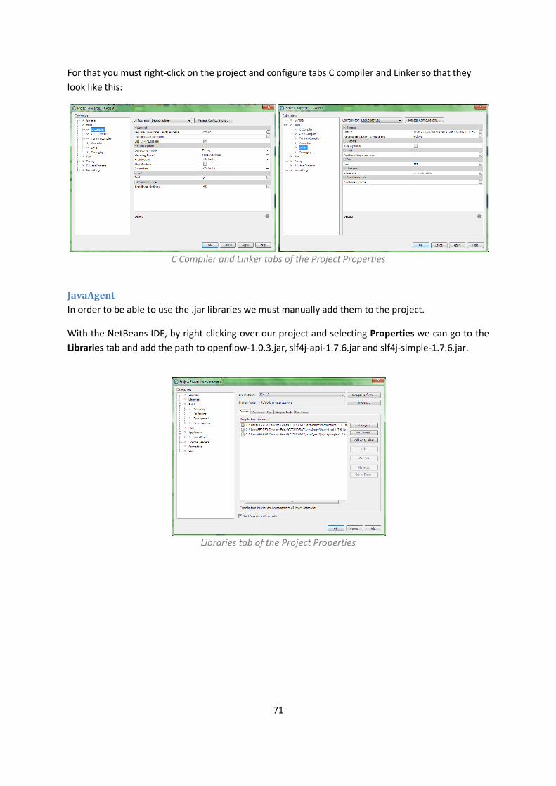
71
For that you must right-click on the project and configure tabs C compiler and Linker so that they
look like this:
C Compiler and Linker tabs of the Project Properties
JavaAgent
In order to be able to use the .jar libraries we must manually add them to the project.
With the NetBeans IDE, by right-clicking over our project and selecting Properties we can go to the
Libraries tab and add the path to openflow-1.0.3.jar, slf4j-api-1.7.6.jar and slf4j-simple-1.7.6.jar.
Libraries tab of the Project Properties

72
Future Work
In this last section I would like to present and comment some of the measures or improvements that
could be applied to the project in general and to the Agent in particular in the foreseeable future.
Priority future work
Extend the Architecture For this thesis I have developed a tool which allows the control of a single OPS, but both the number
of OPS nodes and the amount of resources devoted to them should be further increased so that it
can be actually used in a Data Centre network, with all the requirements of scalability and
performance that this implies and that we have already mentioned.
This increment can be applied in a physical way (buying more equipment) or in a virtual way (making
the OPS share resources, such as making a single FPGA manage various OPS nodes at once) but until
this step is not fully accomplished it would not be possible to test and experiment with more
advanced and interesting topologies and use cases.
In any case, the Agent code has been designed with this purpose on mind so it should only be a
matter of how to provision this scalability in the hardware part (bitfiles and general low-level
programming for the FPGA, actual physical connections between different OPS and ToR, etc.).
DMA communication The usage of the DMA channel for the transmission of large bulks of data at once between the
Cagent and the FPGA would improve greatly the performance of our system.
Reading/writing a single register requires roughly 10 to 16 milliseconds and, if we need to access
more than one, they are simply called one after the other sequentially so that the total amount of
time required scales linearly.
In a DMA communication we have to spend a fixed amount of time (around 45 milliseconds) in the
establishment before the DMA transfer but afterwards, if we increase linearly the amount of data
sent/received it does not incur in a linear increase of time for the whole communication.
Experimentally we demonstrated that the turning point where it was faster establishing a DMA
communication than using sequential accesses to registers was for data transfers of more than 5
registers (20 Bytes).
From the three FPGA communications that our systems performs with the FPGA (LUTentries, Flows
and Counters) it seems that the one which would benefit more from using DMA transfers instead of
registers accesses are the Counters. We will never prefer to access a single counter instead of a full
batch of them (unlike LUTentries and Flows) and if we keep scaling up the system we would need a
way of accessing as many counters at once instead of having to read hundreds or thousands of
individual registers one at a time.

73
Further OF extensions For the OpenFlow channel we have used a modified version of the OpenFlow agent that is included
in the Hydrogen release of OpenDaylight, OpenFlow v1.0.3, with some small modifications such as
using VLANID tag as the packet label and lambda identification or the use of TOS (Type of Service)
match field as an indicator of the nominal load of a flow.
These modifications, while useful and necessary, are not compliant with the OpenFlow specification
and, in any case, there are other functionalities (for instance: Counters per Flow…) that have not yet
been implemented.
For the reasons stated above, at some point in the future it will have to be decided towards which of
the versions of the OpenFlow Switch specification the project is going to work.
Here I will present the possible options and discuss some of their pros and cons:
OpenFlow v1.0.3:
The most simple, clean version of the standard. The version that the ODL Hydrogen uses.
Regarded as “Legacy OpenFlow”, with no active support for its improvement.
OpenFlow v1.3.3:
The most mature and well defined version of the protocol. The ODL can be easily configured to use this version instead of the default 1.0.3. The ODL implementation of the libraries could also be used for the Agent.
Does NOT add anything extra for optical devices.
Note: v1.3.4 was released at the end of March’14 with some minor changes and clarifications.
OpenFlow v1.4.0
Adds some extra features for optical devices (port definitions).
Despite being the newest version change there has been no global effort towards it. Their more important improvements have already been included in v1.3.3. Regarded as a transition specification. The new optical features are very limited.
OpenFlow v1.5
Next great step. Will integrate the maturity of v1.3.4 with real and extensive optical features. Next release of OpenDaylight controller (Helium) is expected to support it.
No estimated time for its release
I would advise to wait for v1.5 and, in the meantime, keep extending the running v1.0.3 or, at most,
change to v1.3.3 and extend it as we have been doing (especially since there is no estimated date for
the v1.5 and, even if it were, then we would have to wait for the Helium release of OpenDaylight).
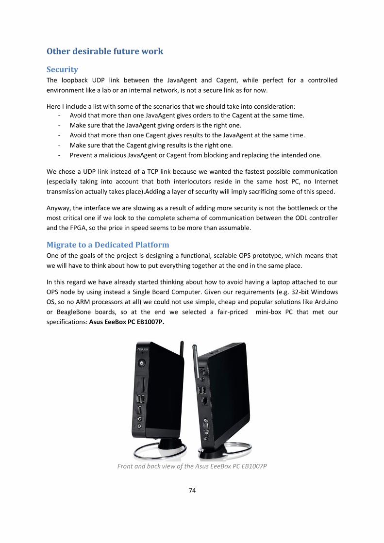
74
Other desirable future work
Security The loopback UDP link between the JavaAgent and Cagent, while perfect for a controlled
environment like a lab or an internal network, is not a secure link as for now.
Here I include a list with some of the scenarios that we should take into consideration: - Avoid that more than one JavaAgent gives orders to the Cagent at the same time.
- Make sure that the JavaAgent giving orders is the right one.
- Avoid that more than one Cagent gives results to the JavaAgent at the same time.
- Make sure that the Cagent giving results is the right one.
- Prevent a malicious JavaAgent or Cagent from blocking and replacing the intended one.
We chose a UDP link instead of a TCP link because we wanted the fastest possible communication
(especially taking into account that both interlocutors reside in the same host PC, no Internet
transmission actually takes place).Adding a layer of security will imply sacrificing some of this speed.
Anyway, the interface we are slowing as a result of adding more security is not the bottleneck or the
most critical one if we look to the complete schema of communication between the ODL controller
and the FPGA, so the price in speed seems to be more than assumable.
Migrate to a Dedicated Platform One of the goals of the project is designing a functional, scalable OPS prototype, which means that
we will have to think about how to put everything together at the end in the same place.
In this regard we have already started thinking about how to avoid having a laptop attached to our
OPS node by using instead a Single Board Computer. Given our requirements (e.g. 32-bit Windows
OS, so no ARM processors at all) we could not use simple, cheap and popular solutions like Arduino
or BeagleBone boards, so at the end we selected a fair-priced mini-box PC that met our
specifications: Asus EeeBox PC EB1007P.
Front and back view of the Asus EeeBox PC EB1007P

75
Specifications
Here I have included a list with its most important technical specifications:
OS Windows 7 Home Premium 32bit
Processor Intel Atom D425(Dual-Core) 1.8 GHz
Processor Cooling Fanned
Memory 2 GB DDR3 800MHz SO-DIMM
HDD 320GB SATAII HDD
PCI Expansion NO
Backpanel I/O
2 USB 2.0 ports VGA port 1 LAN port External Wi-Fi Antenna
Access (Front, Back, Side) 4in1 Card Reader 3 USB 2.0 ports
Operating Temperature 0°C~55°C
Power Requirements ~ 15 W
Size 223 x 178 x 27 mm
The only downsides are that it does not have a PCI port , neither a HDMI video output, but the USB
connection to the FPGA is preferable (so that we can control several ones from the same PC) and
regular PCI connectors have been rendered obsolete by PCI-express since its appearance circa 2004.
The lack of HDMI port is not important as long as it includes a VGA connection which is still a very
common way of connecting to a display.
Change the FPGA At some point in the future the question might arise about whether to keep or change the FPGA that
we are using for the label processing and the interaction with the Agent.
As the project continues advancing also the requirements will change and we could find out that we
need hardware with different specifications. For instance, it is not likely that we require a “faster”
FPGA, as this Virtex4 model is more than enough for the internal computations that it is making, but
we might require a device which could be programmatically accessed faster by the Agent.
With this change we will also have a totally different set of requirements which we could use in our
advantage: if we select a board compatible with Linux or other UNIX systems we could avoid the
dependence on Windows OS (which implies a cost both computational and economical) and, more
specifically for the Cagent, we could completely eliminate the Cygwin emulation layer.
Of course, and this should be taken into consideration, that would mean that a major rework of the
Agent code would be needed, but this could also be regarded as a step in the right direction if we
are then able to simplify and reorganize the code into a single language program (be it C, Java or
even Python given the case) that avoids the loopback socket UDP communication while at the same
time better exploit the strengths of the selected programming language.

76
Conclusion
This document has presented the OpenFlow Agent software for interfacing an OPS switch with the
SDN controller that manages the Control Plane in the Data Centre Network (DCN) architecture
proposed in the Lightness Project.
Apart from presenting the motivation to do so and illustrated some of the uses cases where this tool
can be used, it has also been explained the rationale behind most of the design decisions that had to
be made during its development.
At the end, there have been included some proposals on how this Agent can be further developed
and extended so that its integration in high-performance and scalable next-generation Data Centre
Network implementing a SDN controller to rule over a Data Plane of OCS and OPS switches can be
achieved.

77
Bibliography & References
78
Acronyms
SDN
SDN – Software Defined Networks ODL – Open Daylight IM – Information Model
OpenFlow
OF – OpenFlow OFP – OpenFlow Protocol OFConfig – OpenFlow Configuration Protocol ONF – Open Networking Foundation P4 – Programming Protocol-Independent Packet Processors
Optical Domain
AWG – Arrayed Waveguide Grating DWDM – Dense Wavelength Division Multiplexing OTN – Optical Transport Network OXC – Optical Cross-connect OPS – Optical Packet Switching OBS – Optical Burst Switching OCS – Optical Circuit Switching ROADM – Reconfigurable Optical Add Drop Multiplexer SOA – Semiconductor Optical Amplifier SONET – Synchronous Optical Networking
Programming
DLL – Dynamic-Link Library IDE – Integrated Development Environment POSIX – Portable Operating System Interface JRE – Java Runtime Environment JDK – Java Development Kit
Networking
DC – Data Centre DCN – Data Centre Network LAN – Local Area Network VLAN – Virtual Local Area Network VPN – Virtual Private Network VN - Virtual Network
Protocols
BGP - Border Gateway Protocol MPLS – Multi Protocol Label Switching GMPLS – Generalized MPLS HDLC – High-Level Data Link Control HTTP – Hyper Text Transfer Protocol RSVP – Resource Reservation Protocol LLDP – Link Layer Discovery Protocol IP – Internet Protocol UDP – User Datagram Protocol TCP - Transmission Control Protocol TLS – Transport Layer Security NETCONF- Network Configuration Protocol SNMP – Simple Network Management Protocol XMLP – XML protocol
Other
CPU – Central Processing Unit SP - Service Provider ISP - Internet Service Provider IaaS – Infrastructure as a Service InP – Infrastructure Provider UNI – User-Network Interface VM – Virtual Machine CAPEX – Capital Expenses OPEX – Operational Expenses QoS – Quality of Service PCI – Peripheral Component Interconnect EHCI - Enhanced Host Controller Interface XML - Extensible Mark-up Language
FPGA
Xilinx ISE – Xilinx Integrated Software Development FUSE – Field Upgradeable Systems Environment LUT – Look-Up Table

79
Bibliography
Online References The online references used have been grouped thematically. Because of that, some online
references wide enough to cover in detail several of them, such as the opennetworking.org from the
Open Networking Foundation being a reference for SDN, OpenFlow and even Network Virtualization,
may appear more than once.
SDN
https://www.opennetworking.org - https://www.opennetworking.org/sdn-resources/sdn-definition
- https://www.opennetworking.org/sdn-resources/sdn-library
o https://www.opennetworking.org/sdn-resources/sdn-library/whitepapers
o https://www.opennetworking.org/sdn-resources/sdn-library/solution-briefs
o https://www.opennetworking.org/sdn-resources/sdn-library/technical-papers
http://searchsdn.techtarget.com
- http://searchsdn.techtarget.com/resources/SDN-architecture
- http://searchsdn.techtarget.com/guides
http://www.sdncentral.com/
http://www.opennetsummit.org/
- http://www.opennetsummit.org/archives/apr13/site/why-sdn.html
OpenDaylight
http://www.opendaylight.org/ - https://wiki.opendaylight.org
OpenFlow
https://www.opennetworking.org - https://www.opennetworking.org/sdn-resources/onf-specifications/openflow
http://archive.openflow.org/ - http://archive.openflow.org/wk/index.php/Main_Page
Virtualization & Network Virtualization
https://www.virtualbox.org/
http://mininet.org/
http://www.sdncentral.com/
https://www.opennetworking.org - https://www.opennetworking.org/images/stories/downloads/sdn-resources/solution-
briefs/sb-sdn-nvf-solution.pdf

80
EU Lightness Project
http://www.ict-lightness.eu/ - http://www.ict-lightness.eu/category/deliverable/
FPGA
http://www.xilinx.com/ - http://www.xilinx.com/products/boards-and-kits/DO-DI-DSP-DK4-UNI-G.htm
http://www.nallatech.com/ - http://www.nallatech.com/Development-Kits/virtex-4-xtremedsp-development-kit.html
Programming
http://stackoverflow.com/
https://www.cygwin.com/
https://netbeans.org/ - https://netbeans.org/community/releases/80/index.html
- https://netbeans.org/community/releases/80/cpp-setup-instructions.html
Java
http://www.oracle.com - http://www.oracle.com/technetwork/java/javase/downloads/index.html
http://docs.oracle.com/javase/7/docs/api/index.html
3rd party libraries
http://ezxml.sourceforge.net/
https://www.gnu.org/software/zebra/
http://www.nongnu.org/quagga/
http://www.slf4j.org/

81
Publications “Demonstration of Reconfigurable Virtual Data Center Networks Enabled by OPS with QoS
Guarantees”, W. Miao et al. (2014)
“Experimental Assessment of an SDN-based Control of OPS Switching Nodes for Intra-Data Center
Interconnect”, S.Spadaro et al. (2014)
“Unifying Packet and Circuit Switched Networks”, S. Das, G.Parulkar, N. McKeown
“Why OpenFlow/SDN Can Succeed Where GMPLS Failed”, S. Das, G.Parulkar, N. McKeown
“Simple Unified Control for Packet and Circuit Networks”, S. Das, G.Parulkar, N. McKeown
“Control Plane Solutions for Dynamic and Adaptive Flexi-Grid Optical Networks”, R. Muñoz et al.
“Software-Defined Optical Networks Technology and Infrastructure: Enabling Software-Defined
Optical Network Operations”, M. Channegowda, R. Nejabati, D. Simeonidou,
“Carving Research Slices Out of Your Production Networks with OpenFlow”, R. Sherwood et al.
“Data Center Optical Networks (DCON) with OpenFlow based Software Defined Networking
(SDN)”, Yongli Zhao et al. (2013)
“MiceTrap: Scalable Traffic Engineering of Datacenter Mice Flows using OpenFlow”, Ramona Trestian , Kostas Katrinis et al. (2013)
“Experimental Demonstration of OpenFlow Control of Packet and Circuit Switches”, Vinesh Gudla, Saurav Das et al.
“Packet and Circuit Network Convergence with OpenFlow”, Saurav Das, Guru Parulkar, Nick McKeown, Preeti Singh,
“How to Read a Paper”, S. Keshav (2013)
Documentation
FPGA
Document name: “XtremeDSP Development Kit-IV User Guide” Document number: NT107-0272 Issue number: 2 Date of issue: Jul 2005
Document name: “XtremeDSP Development Kit Getting Started Guide” Document number: NT116-0246 Issue number: 1 Date of issue: Nov 2004
Document name: “FUSE C/C++ API Developer’s Guide” Document number: NT107-0068 Issue number: 8 Date of issue: Jan 2005
Document name: “APPLICATION NOTE: PCI Communications Core” Document number: NT302-0000 Issue number: 6 Date of issue: Sep 2004

82
Annexes
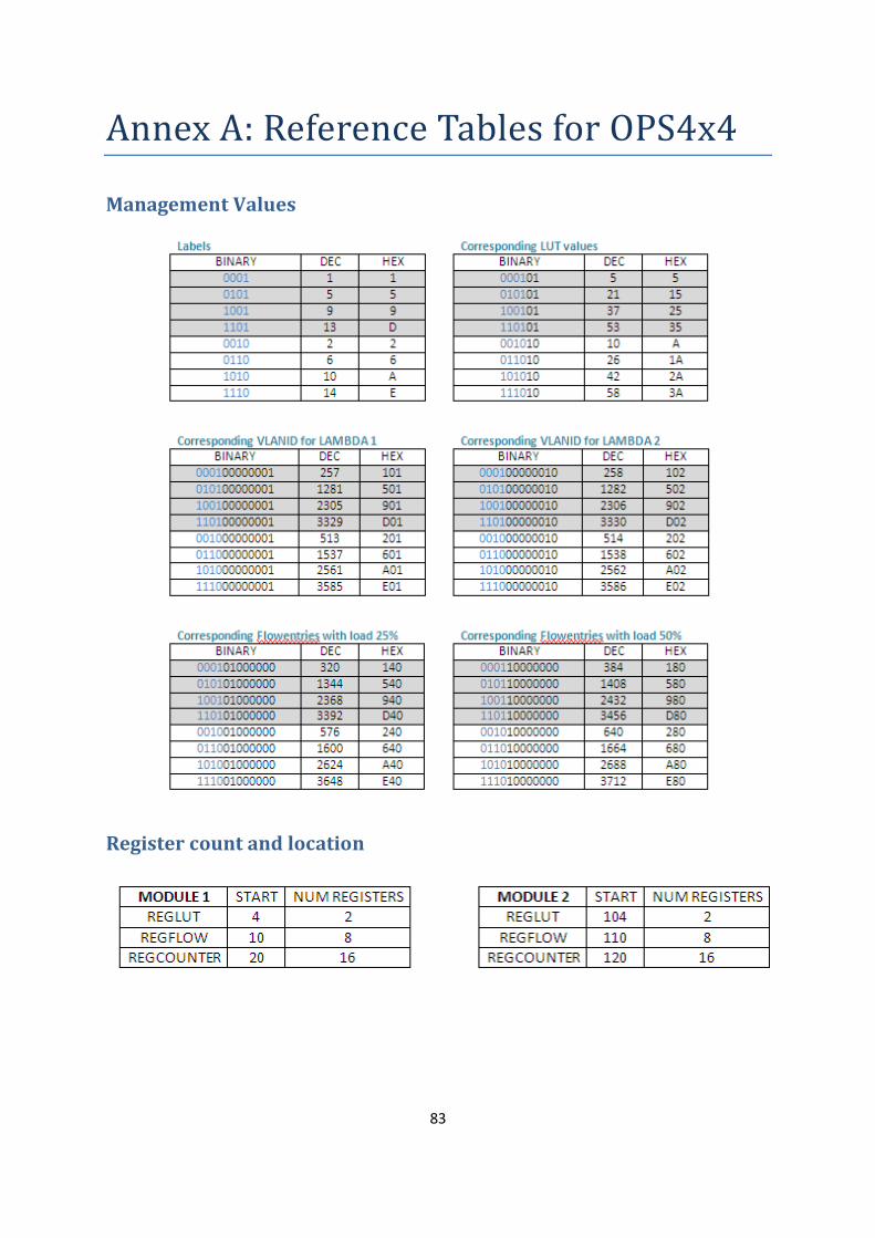
83
Annex A: Reference Tables for OPS4x4
Management Values
Register count and location

84
Annex B: Publications & Awards
Publications Two Papers were written while developing this thesis as part of the Lightness project and were
accepted at the European Conference on Optical Communication (ECOC) for a poster presentation
and for an oral presentation respectively.
I am listed in both papers as a co-author as part of the team that made them possible due to my
contribution in the data collection and experimental validation.
Selected for Poster Presentation – “Demonstration of Reconfigurable Virtual Data Centre Networks
Enabled by OPS with QoS Guarantees”, W. Miao et al. (2014)
Selected for Oral Presentation – “Experimental Assessment of an SDN-based Control of OPS
Switching Nodes for Intra-Data Centre Interconnect”, S.Spadaro et al. (2014)
Awards On Wednesday 25th of June of 2014, during the European Conference on Networks and
Communications (EuCNC) in Bologna (Italy), a demonstration of the Lightness Project’s architecture
system that included the OPS prototype and the Agent developed as part of this thesis received the
Best Booth Award of the conference.
85
Annex C: Source files & Contact details
Agent’s Code and source files The code and source files used for the project have been given to dr. Nicola Calabretta and dr.
Salvatore Spadaro, supervisors of this thesis.
Contact Details The author of this thesis can be contacted through the following mail address: