sdk reference manual 3.1 rev2.b
TRANSCRIPT
8/9/2019 SDK Reference Manual 3.1 Rev2.B
http://slidepdf.com/reader/full/sdk-reference-manual-31-rev2b 1/204
Software Development Kit
Reference Manual
Software Version 3.1
Document No. 06-RM-1600 Revision: 2.B
30 September 2010

8/9/2019 SDK Reference Manual 3.1 Rev2.B
http://slidepdf.com/reader/full/sdk-reference-manual-31-rev2b 2/204

8/9/2019 SDK Reference Manual 3.1 Rev2.B
http://slidepdf.com/reader/full/sdk-reference-manual-31-rev2b 3/204
SDK Reference Manual Contents overview
Document No. 06-RM-1600 Revision: 2.B 3
ClearSpeed Technology Ltd
Contents overview
This manual consists of two parts: firstly a set of reference chapters for all the tools, followed
by a number of chapters describing the programming languages and file formats. The fol-lowing is a summary of the contents of each chapter.
Part 1: Tools
1 SDK overview . . . . . . . . . . . . . . . . . . . . . . . . . . . . . . . . . . . . . . . . . . . . . . 12
Gives an overview of the tool chain.
2 Building programs . . . . . . . . . . . . . . . . . . . . . . . . . . . . . . . . . . . . . . . . . . 18
Describes the command-line options and parameters used for compiling and building pro-grams.
3 The preprocessor. . . . . . . . . . . . . . . . . . . . . . . . . . . . . . . . . . . . . . . . . . . 35
Documents the preprocessor, how to invoke it and command-line options.
4 Compiler reference. . . . . . . . . . . . . . . . . . . . . . . . . . . . . . . . . . . . . . . . . . 37
Describes how to invoke the compiler and the command-line options and parameters usedfor compiling programs.
5 Macro assembler reference. . . . . . . . . . . . . . . . . . . . . . . . . . . . . . . . . . . 52
Describes how to invoke the assembler and its options and parameters.
6 Linker reference . . . . . . . . . . . . . . . . . . . . . . . . . . . . . . . . . . . . . . . . . . . . 56
Describes how the linker works and how code and data are organized in memory.
7 Debugger reference . . . . . . . . . . . . . . . . . . . . . . . . . . . . . . . . . . . . . . . . . 65
Describes the features and use of the symbolic source code debugger.
8 Simulators reference . . . . . . . . . . . . . . . . . . . . . . . . . . . . . . . . . . . . . . . . 92
Explains how to use the simulator to run programs in the absence of hardware.
9 Archiver. . . . . . . . . . . . . . . . . . . . . . . . . . . . . . . . . . . . . . . . . . . . . . . . . . 100
A utility for creating libraries of object code.
8/9/2019 SDK Reference Manual 3.1 Rev2.B
http://slidepdf.com/reader/full/sdk-reference-manual-31-rev2b 4/204
Contents overview SDK Reference Manual
4 Document No. 06-RM-1600 Revision: 2.B
ClearSpeed Technology LtdLtd
10 Object file dump . . . . . . . . . . . . . . . . . . . . . . . . . . . . . . . . . . . . . . . . . . . 101
A tool for examining the contents of object files and generating disassembly listings.
Part 2: Programming
11 The Cn language. . . . . . . . . . . . . . . . . . . . . . . . . . . . . . . . . . . . . . . . . . . 105
Describes the main features of the Cn language, focusing on the differences between it and ANSI standard C. Explains the new parallel data types supported by the compiler and howthey are used in a program.
12 Memory use . . . . . . . . . . . . . . . . . . . . . . . . . . . . . . . . . . . . . . . . . . . . . . 150
This section summarizes the various features of the tool chain related to making efficient useof code and data memory.
13 Application binary interface . . . . . . . . . . . . . . . . . . . . . . . . . . . . . . . . . 157
A specification of the software interface used between object files compiled with the SDK:program start-up, how the various data types are stored in memory, and the function callingand parameter passing conventions.
14 Assembly language . . . . . . . . . . . . . . . . . . . . . . . . . . . . . . . . . . . . . . . . 179
Defines the syntax of the assembly language for CSX processor cores and the directives sup-ported by the assembler.
15 Bibliography . . . . . . . . . . . . . . . . . . . . . . . . . . . . . . . . . . . . . . . . . . . . . . 202
References to sources of further information.
8/9/2019 SDK Reference Manual 3.1 Rev2.B
http://slidepdf.com/reader/full/sdk-reference-manual-31-rev2b 5/204
SDK Reference Manual Table of contents
Document No. 06-RM-1600 Revision: 2.B 5
ClearSpeed Technology Ltd
Table of contents
1 SDK overview . . . . . . . . . . . . . . . . . . . . . . . . . . . . . . . . . . . . . . . . . . . . . 12
1.1 A brief description of the software development tools . . . . . . . . . . . . . . . 12
1.2 Command line . . . . . . . . . . . . . . . . . . . . . . . . . . . . . . . . . . . . . . . . . . . . . 13
1.2.1 Syntax . . . . . . . . . . . . . . . . . . . . . . . . . . . . . . . . . . . . . . . . . . . . . . . . . . 13
1.2.2 Options . . . . . . . . . . . . . . . . . . . . . . . . . . . . . . . . . . . . . . . . . . . . . . . . . 14
1.2.3 Generic options . . . . . . . . . . . . . . . . . . . . . . . . . . . . . . . . . . . . . . . . . . . 14
1.3 File naming conventions . . . . . . . . . . . . . . . . . . . . . . . . . . . . . . . . . . . . . . 14
1.4 Libraries . . . . . . . . . . . . . . . . . . . . . . . . . . . . . . . . . . . . . . . . . . . . . . . . . . 15
1.5 Header files . . . . . . . . . . . . . . . . . . . . . . . . . . . . . . . . . . . . . . . . . . . . . . . 15
1.6 Environment variables . . . . . . . . . . . . . . . . . . . . . . . . . . . . . . . . . . . . . . . 15
1.7 Predefined macros . . . . . . . . . . . . . . . . . . . . . . . . . . . . . . . . . . . . . . . . . . 16
1.8 Error reporting . . . . . . . . . . . . . . . . . . . . . . . . . . . . . . . . . . . . . . . . . . . . . 16
1.9 Configuration file . . . . . . . . . . . . . . . . . . . . . . . . . . . . . . . . . . . . . . . . . . . 17
1.10 Licensing and open source components . . . . . . . . . . . . . . . . . . . . . . . . . 17
2 Building programs . . . . . . . . . . . . . . . . . . . . . . . . . . . . . . . . . . . . . . . . . 18
2.1 Hello world . . . . . . . . . . . . . . . . . . . . . . . . . . . . . . . . . . . . . . . . . . . . . . . . 18
2.2 Multiple source files . . . . . . . . . . . . . . . . . . . . . . . . . . . . . . . . . . . . . . . . . 18
2.3 Processing performed by cscn . . . . . . . . . . . . . . . . . . . . . . . . . . . . . . . . . 19
2.4 Invoking cscn . . . . . . . . . . . . . . . . . . . . . . . . . . . . . . . . . . . . . . . . . . . . . . 20
2.4.1 Generic options . . . . . . . . . . . . . . . . . . . . . . . . . . . . . . . . . . . . . . . . . . . 20
2.4.2 Preprocessor options . . . . . . . . . . . . . . . . . . . . . . . . . . . . . . . . . . . . . . . 20
2.4.3 Compiler options . . . . . . . . . . . . . . . . . . . . . . . . . . . . . . . . . . . . . . . . . . 22
2.4.4 Assembler options . . . . . . . . . . . . . . . . . . . . . . . . . . . . . . . . . . . . . . . . . 27
2.4.5 Linker options . . . . . . . . . . . . . . . . . . . . . . . . . . . . . . . . . . . . . . . . . . . . 28
3 The preprocessor . . . . . . . . . . . . . . . . . . . . . . . . . . . . . . . . . . . . . . . . . . 35
3.1 Invoking the preprocessor . . . . . . . . . . . . . . . . . . . . . . . . . . . . . . . . . . . . 35
3.2 Command-line options . . . . . . . . . . . . . . . . . . . . . . . . . . . . . . . . . . . . . . . 35
4 Compiler reference . . . . . . . . . . . . . . . . . . . . . . . . . . . . . . . . . . . . . . . . . 37
4.1 Invoking the compiler . . . . . . . . . . . . . . . . . . . . . . . . . . . . . . . . . . . . . . . . 37
4.2 Command-line options . . . . . . . . . . . . . . . . . . . . . . . . . . . . . . . . . . . . . . . 37
8/9/2019 SDK Reference Manual 3.1 Rev2.B
http://slidepdf.com/reader/full/sdk-reference-manual-31-rev2b 6/204
Table of contents SDK Reference Manual
6 Document No. 06-RM-1600 Revision: 2.B
ClearSpeed Technology Ltd
4.3 Function inlining . . . . . . . . . . . . . . . . . . . . . . . . . . . . . . . . . . . . . . . . . . . . 41
4.3.1 Conditions on inlining . . . . . . . . . . . . . . . . . . . . . . . . . . . . . . . . . . . . . . . 42
4.3.2 User controls . . . . . . . . . . . . . . . . . . . . . . . . . . . . . . . . . . . . . . . . . . . . . 42
4.4 Compiler optimizations . . . . . . . . . . . . . . . . . . . . . . . . . . . . . . . . . . . . . . . 44
4.4.1 Dead object removal . . . . . . . . . . . . . . . . . . . . . . . . . . . . . . . . . . . . . . . 45
4.4.2 Constant evaluation . . . . . . . . . . . . . . . . . . . . . . . . . . . . . . . . . . . . . . . . 45
4.4.3 Switch transformation . . . . . . . . . . . . . . . . . . . . . . . . . . . . . . . . . . . . . . 46
4.4.4 Global register allocation . . . . . . . . . . . . . . . . . . . . . . . . . . . . . . . . . . . . 46
4.4.5 Basic-block ordering . . . . . . . . . . . . . . . . . . . . . . . . . . . . . . . . . . . . . . . 46
4.4.6 Share-string initializers . . . . . . . . . . . . . . . . . . . . . . . . . . . . . . . . . . . . . 46
4.4.7 Dead block removal . . . . . . . . . . . . . . . . . . . . . . . . . . . . . . . . . . . . . . . . 46
4.4.8 Basic-block merging . . . . . . . . . . . . . . . . . . . . . . . . . . . . . . . . . . . . . . . 46
4.4.9 Move post-operator assignments . . . . . . . . . . . . . . . . . . . . . . . . . . . . . 47
4.4.10 Copy propagation . . . . . . . . . . . . . . . . . . . . . . . . . . . . . . . . . . . . . . . . . 47
4.4.11 Strength reduction . . . . . . . . . . . . . . . . . . . . . . . . . . . . . . . . . . . . . . . . . 47
4.4.12 Constant propagation . . . . . . . . . . . . . . . . . . . . . . . . . . . . . . . . . . . . . . 47
4.4.13 Dead code removal . . . . . . . . . . . . . . . . . . . . . . . . . . . . . . . . . . . . . . . . 47
4.4.14 Live range splitting . . . . . . . . . . . . . . . . . . . . . . . . . . . . . . . . . . . . . . . . . 47
4.4.15 Global register preallocation . . . . . . . . . . . . . . . . . . . . . . . . . . . . . . . . . 47
4.4.16 Common subexpression elimination . . . . . . . . . . . . . . . . . . . . . . . . . . . 48
4.4.17 Tail recursion elimination . . . . . . . . . . . . . . . . . . . . . . . . . . . . . . . . . . . . 48
4.4.18 Loop invariant code motion . . . . . . . . . . . . . . . . . . . . . . . . . . . . . . . . . . 48
4.4.19 Tail merging . . . . . . . . . . . . . . . . . . . . . . . . . . . . . . . . . . . . . . . . . . . . . . 48
4.4.20 Algebraic simplification . . . . . . . . . . . . . . . . . . . . . . . . . . . . . . . . . . . . . 48
4.4.21 Chain flow optimization . . . . . . . . . . . . . . . . . . . . . . . . . . . . . . . . . . . . . 49
4.4.22 Peephole optimizer . . . . . . . . . . . . . . . . . . . . . . . . . . . . . . . . . . . . . . . . 49
4.4.23 Scalar replacement . . . . . . . . . . . . . . . . . . . . . . . . . . . . . . . . . . . . . . . . 49
4.4.24 Remove empty loops . . . . . . . . . . . . . . . . . . . . . . . . . . . . . . . . . . . . . . . 49
4.4.25 Loop inversion . . . . . . . . . . . . . . . . . . . . . . . . . . . . . . . . . . . . . . . . . . . . 49
4.4.26 Expression-level scheduler . . . . . . . . . . . . . . . . . . . . . . . . . . . . . . . . . . 494.4.27 ld/st offset normalization . . . . . . . . . . . . . . . . . . . . . . . . . . . . . . . . . . . . 49
4.4.28 Instruction-level scheduler . . . . . . . . . . . . . . . . . . . . . . . . . . . . . . . . . . . 50
4.4.29 Loop reversal . . . . . . . . . . . . . . . . . . . . . . . . . . . . . . . . . . . . . . . . . . . . . 50
4.4.30 Loop fusion . . . . . . . . . . . . . . . . . . . . . . . . . . . . . . . . . . . . . . . . . . . . . . 50
4.4.31 Loop scalar replacement . . . . . . . . . . . . . . . . . . . . . . . . . . . . . . . . . . . . 50
4.4.32 Loop strength reduction . . . . . . . . . . . . . . . . . . . . . . . . . . . . . . . . . . . . . 50
4.4.33 Loop induction variable elimination . . . . . . . . . . . . . . . . . . . . . . . . . . . . 51
8/9/2019 SDK Reference Manual 3.1 Rev2.B
http://slidepdf.com/reader/full/sdk-reference-manual-31-rev2b 7/204
SDK Reference Manual Table of contents
Document No. 06-RM-1600 Revision: 2.B 7
ClearSpeed Technology Ltd
4.4.34 Loop unrolling . . . . . . . . . . . . . . . . . . . . . . . . . . . . . . . . . . . . . . . . . . . . 51
5 Macro assembler reference . . . . . . . . . . . . . . . . . . . . . . . . . . . . . . . . . . 52
5.1 Invoking the assembler . . . . . . . . . . . . . . . . . . . . . . . . . . . . . . . . . . . . . . 525.2 Command-line options . . . . . . . . . . . . . . . . . . . . . . . . . . . . . . . . . . . . . . . 52
6 Linker reference . . . . . . . . . . . . . . . . . . . . . . . . . . . . . . . . . . . . . . . . . . . 56
6.1 Basic terminology and concepts . . . . . . . . . . . . . . . . . . . . . . . . . . . . . . . . 56
6.2 Invoking the linker . . . . . . . . . . . . . . . . . . . . . . . . . . . . . . . . . . . . . . . . . . 56
6.3 Command-line options . . . . . . . . . . . . . . . . . . . . . . . . . . . . . . . . . . . . . . . 56
6.3.1 Category: files and paths . . . . . . . . . . . . . . . . . . . . . . . . . . . . . . . . . . . . 58
6.3.2 Category: file layout . . . . . . . . . . . . . . . . . . . . . . . . . . . . . . . . . . . . . . . . 59
6.3.3 Category: map . . . . . . . . . . . . . . . . . . . . . . . . . . . . . . . . . . . . . . . . . . . . 59
6.3.4 Category: symbols . . . . . . . . . . . . . . . . . . . . . . . . . . . . . . . . . . . . . . . . . 60
6.3.5 Category: other . . . . . . . . . . . . . . . . . . . . . . . . . . . . . . . . . . . . . . . . . . . 61
6.4 File layout . . . . . . . . . . . . . . . . . . . . . . . . . . . . . . . . . . . . . . . . . . . . . . . . . 62
6.5 Order of processing input files . . . . . . . . . . . . . . . . . . . . . . . . . . . . . . . . . 63
6.6 Search paths . . . . . . . . . . . . . . . . . . . . . . . . . . . . . . . . . . . . . . . . . . . . . . 64
6.7 Example . . . . . . . . . . . . . . . . . . . . . . . . . . . . . . . . . . . . . . . . . . . . . . . . . . 64
6.8 Related tools . . . . . . . . . . . . . . . . . . . . . . . . . . . . . . . . . . . . . . . . . . . . . . 64
7 Debugger reference . . . . . . . . . . . . . . . . . . . . . . . . . . . . . . . . . . . . . . . . 65
7.1 New commands and features . . . . . . . . . . . . . . . . . . . . . . . . . . . . . . . . . . 65
7.2 Invoking the debugger . . . . . . . . . . . . . . . . . . . . . . . . . . . . . . . . . . . . . . . 65
7.3 Using the debugger with a host application . . . . . . . . . . . . . . . . . . . . . . . 65
7.3.1 Connecting to multiple processors . . . . . . . . . . . . . . . . . . . . . . . . . . . . . 66
7.3.2 Connecting to the processor manually . . . . . . . . . . . . . . . . . . . . . . . . . 67
7.4 Commands . . . . . . . . . . . . . . . . . . . . . . . . . . . . . . . . . . . . . . . . . . . . . . . . 67
7.4.1 Connect command and options . . . . . . . . . . . . . . . . . . . . . . . . . . . . . . . 67
7.4.2 Loading code . . . . . . . . . . . . . . . . . . . . . . . . . . . . . . . . . . . . . . . . . . . . . 69
7.4.3 Executing code . . . . . . . . . . . . . . . . . . . . . . . . . . . . . . . . . . . . . . . . . . . 69
7.4.4 Mono debugging . . . . . . . . . . . . . . . . . . . . . . . . . . . . . . . . . . . . . . . . . . 69
7.4.5 Poly debugging . . . . . . . . . . . . . . . . . . . . . . . . . . . . . . . . . . . . . . . . . . . 73
7.4.6 Hardware threads . . . . . . . . . . . . . . . . . . . . . . . . . . . . . . . . . . . . . . . . . 77
7.4.7 System register viewer . . . . . . . . . . . . . . . . . . . . . . . . . . . . . . . . . . . . . 79
7.4.8 TSC semaphore viewer . . . . . . . . . . . . . . . . . . . . . . . . . . . . . . . . . . . . . 83

8/9/2019 SDK Reference Manual 3.1 Rev2.B
http://slidepdf.com/reader/full/sdk-reference-manual-31-rev2b 8/204
Table of contents SDK Reference Manual
8 Document No. 06-RM-1600 Revision: 2.B
ClearSpeed Technology Ltd
7.5 Registers . . . . . . . . . . . . . . . . . . . . . . . . . . . . . . . . . . . . . . . . . . . . . . . . . 90
7.6 Using DDD . . . . . . . . . . . . . . . . . . . . . . . . . . . . . . . . . . . . . . . . . . . . . . . . 90
8 Simulators reference . . . . . . . . . . . . . . . . . . . . . . . . . . . . . . . . . . . . . . . . 928.1 Invoking the simulator . . . . . . . . . . . . . . . . . . . . . . . . . . . . . . . . . . . . . . . 92
8.2 Command-line options . . . . . . . . . . . . . . . . . . . . . . . . . . . . . . . . . . . . . . . 92
8.2.1 Command line options for isim . . . . . . . . . . . . . . . . . . . . . . . . . . . . . . . 93
8.2.2 Command line options for casim . . . . . . . . . . . . . . . . . . . . . . . . . . . . . . 94
8.3 Simulating multiple CSX processors . . . . . . . . . . . . . . . . . . . . . . . . . . . . 95
8.4 Errors . . . . . . . . . . . . . . . . . . . . . . . . . . . . . . . . . . . . . . . . . . . . . . . . . . . . 96
8.5 Profiling . . . . . . . . . . . . . . . . . . . . . . . . . . . . . . . . . . . . . . . . . . . . . . . . . . 96
8.5.1 Profiler trace file production on casim . . . . . . . . . . . . . . . . . . . . . . . . . . 968.6 Instruction profiling on isim . . . . . . . . . . . . . . . . . . . . . . . . . . . . . . . . . . . . 98
9 Archiver . . . . . . . . . . . . . . . . . . . . . . . . . . . . . . . . . . . . . . . . . . . . . . . . . 100
9.1 Invoking the archiver . . . . . . . . . . . . . . . . . . . . . . . . . . . . . . . . . . . . . . . 100
9.2 Command-line options . . . . . . . . . . . . . . . . . . . . . . . . . . . . . . . . . . . . . . 100
10 Object file dump . . . . . . . . . . . . . . . . . . . . . . . . . . . . . . . . . . . . . . . . . . 101
10.1 Invoking csdump . . . . . . . . . . . . . . . . . . . . . . . . . . . . . . . . . . . . . . . . . . 101
10.2 Command-line options . . . . . . . . . . . . . . . . . . . . . . . . . . . . . . . . . . . . . . 101
11 The Cn language . . . . . . . . . . . . . . . . . . . . . . . . . . . . . . . . . . . . . . . . . . 105
11.1 Summary of differences from ANSI C . . . . . . . . . . . . . . . . . . . . . . . . . . 105
11.2 Glossary of terms . . . . . . . . . . . . . . . . . . . . . . . . . . . . . . . . . . . . . . . . . . 105
11.3 Comments . . . . . . . . . . . . . . . . . . . . . . . . . . . . . . . . . . . . . . . . . . . . . . . 106
11.4 Data types . . . . . . . . . . . . . . . . . . . . . . . . . . . . . . . . . . . . . . . . . . . . . . . 106
11.4.1 Basic types . . . . . . . . . . . . . . . . . . . . . . . . . . . . . . . . . . . . . . . . . . . . . 106
11.4.2 Derived types . . . . . . . . . . . . . . . . . . . . . . . . . . . . . . . . . . . . . . . . . . . . 106
11.5 Mono and poly types . . . . . . . . . . . . . . . . . . . . . . . . . . . . . . . . . . . . . . . 106
11.5.1 Basic types . . . . . . . . . . . . . . . . . . . . . . . . . . . . . . . . . . . . . . . . . . . . . 107
11.5.2 Pointer declaration . . . . . . . . . . . . . . . . . . . . . . . . . . . . . . . . . . . . . . . . 107
11.5.3 Array types . . . . . . . . . . . . . . . . . . . . . . . . . . . . . . . . . . . . . . . . . . . . . . 110
11.5.4 Struct and union types . . . . . . . . . . . . . . . . . . . . . . . . . . . . . . . . . . . . . 110
11.5.5 Typedefs . . . . . . . . . . . . . . . . . . . . . . . . . . . . . . . . . . . . . . . . . . . . . . . 112
8/9/2019 SDK Reference Manual 3.1 Rev2.B
http://slidepdf.com/reader/full/sdk-reference-manual-31-rev2b 9/204
SDK Reference Manual Table of contents
Document No. 06-RM-1600 Revision: 2.B 9
ClearSpeed Technology Ltd
11.6 Assignment . . . . . . . . . . . . . . . . . . . . . . . . . . . . . . . . . . . . . . . . . . . . . . . 112
11.6.1 Pointer dereferencing . . . . . . . . . . . . . . . . . . . . . . . . . . . . . . . . . . . . . 113
11.7 Expressions . . . . . . . . . . . . . . . . . . . . . . . . . . . . . . . . . . . . . . . . . . . . . . 113
11.7.1 Casting . . . . . . . . . . . . . . . . . . . . . . . . . . . . . . . . . . . . . . . . . . . . . . . . . 114
11.8 Flow Control . . . . . . . . . . . . . . . . . . . . . . . . . . . . . . . . . . . . . . . . . . . . . . 114
11.8.1 Poly flow control . . . . . . . . . . . . . . . . . . . . . . . . . . . . . . . . . . . . . . . . . . 115
11.8.2 If statements . . . . . . . . . . . . . . . . . . . . . . . . . . . . . . . . . . . . . . . . . . . . 115
11.8.3 Switch statements . . . . . . . . . . . . . . . . . . . . . . . . . . . . . . . . . . . . . . . . 118
11.8.4 For, while and do...while loops . . . . . . . . . . . . . . . . . . . . . . . . . . . . . . 119
11.9 Functions . . . . . . . . . . . . . . . . . . . . . . . . . . . . . . . . . . . . . . . . . . . . . . . . 124
11.9.1 Function multiplicity . . . . . . . . . . . . . . . . . . . . . . . . . . . . . . . . . . . . . . . 124
11.9.2 Returning from functions . . . . . . . . . . . . . . . . . . . . . . . . . . . . . . . . . . . 124
11.10 Pragmas . . . . . . . . . . . . . . . . . . . . . . . . . . . . . . . . . . . . . . . . . . . . . . . . . 125
11.10.1 Including assembler macros in Cn . . . . . . . . . . . . . . . . . . . . . . . . . . . . . . . . . . . . . . . . 125
11.10.2 Forcing the alignment of identifiers . . . . . . . . . . . . . . . . . . . . . . . . . . . 125
11.10.3 Generating jump tables for switch statements . . . . . . . . . . . . . . . . . . . 125
11.10.4 Unrolling loops . . . . . . . . . . . . . . . . . . . . . . . . . . . . . . . . . . . . . . . . . . . 126
11.10.5 Moving code to on-chip memory . . . . . . . . . . . . . . . . . . . . . . . . . . . . . 126
11.10.6 Setting stack sizes . . . . . . . . . . . . . . . . . . . . . . . . . . . . . . . . . . . . . . . . 127
11.10.7 Controlling inlining functions . . . . . . . . . . . . . . . . . . . . . . . . . . . . . . . . 127
11.11 Inline assembler . . . . . . . . . . . . . . . . . . . . . . . . . . . . . . . . . . . . . . . . . . . 128
11.11.1 Enable state . . . . . . . . . . . . . . . . . . . . . . . . . . . . . . . . . . . . . . . . . . . . . 128
11.11.2 Use of variables within assembler code . . . . . . . . . . . . . . . . . . . . . . . 128
11.11.3 Specifying constraints on register use . . . . . . . . . . . . . . . . . . . . . . . . . 129
11.11.4 Constraint directives . . . . . . . . . . . . . . . . . . . . . . . . . . . . . . . . . . . . . . 131
11.11.5 Inline assembly example . . . . . . . . . . . . . . . . . . . . . . . . . . . . . . . . . . . 137
11.12 Vector intrinsics . . . . . . . . . . . . . . . . . . . . . . . . . . . . . . . . . . . . . . . . . . . 137
11.13 Operator overloading . . . . . . . . . . . . . . . . . . . . . . . . . . . . . . . . . . . . . . . 139
11.14 Supported intrinsics . . . . . . . . . . . . . . . . . . . . . . . . . . . . . . . . . . . . . . . . 141
11.14.1 Arithmetic operations . . . . . . . . . . . . . . . . . . . . . . . . . . . . . . . . . . . . . . 142
11.14.2 Cast operations . . . . . . . . . . . . . . . . . . . . . . . . . . . . . . . . . . . . . . . . . . 143
11.14.3 Reduce operations . . . . . . . . . . . . . . . . . . . . . . . . . . . . . . . . . . . . . . . . 144
11.14.4 Selection operations . . . . . . . . . . . . . . . . . . . . . . . . . . . . . . . . . . . . . . 144
11.14.5 Constructor operations . . . . . . . . . . . . . . . . . . . . . . . . . . . . . . . . . . . . 145
11.15 Reserved keywords . . . . . . . . . . . . . . . . . . . . . . . . . . . . . . . . . . . . . . . . 145
11.16 Supported operators . . . . . . . . . . . . . . . . . . . . . . . . . . . . . . . . . . . . . . . . 146
8/9/2019 SDK Reference Manual 3.1 Rev2.B
http://slidepdf.com/reader/full/sdk-reference-manual-31-rev2b 10/204
Table of contents SDK Reference Manual
10 Document No. 06-RM-1600 Revision: 2.B
ClearSpeed Technology Ltd
11.16.1 Unary operators . . . . . . . . . . . . . . . . . . . . . . . . . . . . . . . . . . . . . . . . . . 146
11.16.2 Binary operators . . . . . . . . . . . . . . . . . . . . . . . . . . . . . . . . . . . . . . . . . 146
11.16.3 Assignment operators . . . . . . . . . . . . . . . . . . . . . . . . . . . . . . . . . . . . . 147
11.16.4 Miscellaneous operators . . . . . . . . . . . . . . . . . . . . . . . . . . . . . . . . . . . 14711.16.5 Operator precedence . . . . . . . . . . . . . . . . . . . . . . . . . . . . . . . . . . . . . . 148
12 Memory use . . . . . . . . . . . . . . . . . . . . . . . . . . . . . . . . . . . . . . . . . . . . . . 150
12.1 Stack allocation . . . . . . . . . . . . . . . . . . . . . . . . . . . . . . . . . . . . . . . . . . . 150
12.1.1 Stack size definition . . . . . . . . . . . . . . . . . . . . . . . . . . . . . . . . . . . . . . . 150
12.2 Stack checking . . . . . . . . . . . . . . . . . . . . . . . . . . . . . . . . . . . . . . . . . . . . 152
12.2.1 Run-time stack checking . . . . . . . . . . . . . . . . . . . . . . . . . . . . . . . . . . . 152
12.2.2 Stack frame size checking . . . . . . . . . . . . . . . . . . . . . . . . . . . . . . . . . . 152
12.3 Support for ECC memory . . . . . . . . . . . . . . . . . . . . . . . . . . . . . . . . . . . . 152
12.4 Advance card memory map . . . . . . . . . . . . . . . . . . . . . . . . . . . . . . . . . . 153
12.4.1 Host memory map . . . . . . . . . . . . . . . . . . . . . . . . . . . . . . . . . . . . . . . . 154
13 Application binary interface . . . . . . . . . . . . . . . . . . . . . . . . . . . . . . . . . 157
13.1 Overview of the ABI . . . . . . . . . . . . . . . . . . . . . . . . . . . . . . . . . . . . . . . . 157
13.2 Process startup . . . . . . . . . . . . . . . . . . . . . . . . . . . . . . . . . . . . . . . . . . . 157
13.2.1 Multithreaded code . . . . . . . . . . . . . . . . . . . . . . . . . . . . . . . . . . . . . . . 158
13.2.2 Program termination . . . . . . . . . . . . . . . . . . . . . . . . . . . . . . . . . . . . . . 158
13.3 Data representation and allocation . . . . . . . . . . . . . . . . . . . . . . . . . . . . . 158
13.3.1 Data types . . . . . . . . . . . . . . . . . . . . . . . . . . . . . . . . . . . . . . . . . . . . . . 158
13.3.2 Memory model . . . . . . . . . . . . . . . . . . . . . . . . . . . . . . . . . . . . . . . . . . . 162
13.3.3 Register model . . . . . . . . . . . . . . . . . . . . . . . . . . . . . . . . . . . . . . . . . . . 163
13.4 Calling functions . . . . . . . . . . . . . . . . . . . . . . . . . . . . . . . . . . . . . . . . . . . 165
13.4.1 Calling sequence . . . . . . . . . . . . . . . . . . . . . . . . . . . . . . . . . . . . . . . . . 165
13.4.2 Call stack . . . . . . . . . . . . . . . . . . . . . . . . . . . . . . . . . . . . . . . . . . . . . . . 168
13.4.3 Variable allocation and parameter passing . . . . . . . . . . . . . . . . . . . . . 169
13.4.4 Functions with variable number of parameters . . . . . . . . . . . . . . . . . . 170
13.4.5 Status and predicate bits . . . . . . . . . . . . . . . . . . . . . . . . . . . . . . . . . . . 173
13.4.6 Enable state . . . . . . . . . . . . . . . . . . . . . . . . . . . . . . . . . . . . . . . . . . . . . 173
13.5 Poly scratch memory . . . . . . . . . . . . . . . . . . . . . . . . . . . . . . . . . . . . . . . 173
13.6 Semaphores . . . . . . . . . . . . . . . . . . . . . . . . . . . . . . . . . . . . . . . . . . . . . . 174
13.7 Endianness . . . . . . . . . . . . . . . . . . . . . . . . . . . . . . . . . . . . . . . . . . . . . . 175
13.8 Debugging information format . . . . . . . . . . . . . . . . . . . . . . . . . . . . . . . . 176

8/9/2019 SDK Reference Manual 3.1 Rev2.B
http://slidepdf.com/reader/full/sdk-reference-manual-31-rev2b 11/204
SDK Reference Manual Table of contents
Document No. 06-RM-1600 Revision: 2.B 11
ClearSpeed Technology Ltd
13.8.1 DWARF extensions . . . . . . . . . . . . . . . . . . . . . . . . . . . . . . . . . . . . . . . 176
13.8.2 DWARF virtual register mapping . . . . . . . . . . . . . . . . . . . . . . . . . . . . . 176
14 Assembly language . . . . . . . . . . . . . . . . . . . . . . . . . . . . . . . . . . . . . . . . 17914.1 Overview . . . . . . . . . . . . . . . . . . . . . . . . . . . . . . . . . . . . . . . . . . . . . . . . 179
14.2 Basic syntax . . . . . . . . . . . . . . . . . . . . . . . . . . . . . . . . . . . . . . . . . . . . . . 179
14.2.1 Labels . . . . . . . . . . . . . . . . . . . . . . . . . . . . . . . . . . . . . . . . . . . . . . . . . 179
14.2.2 Instructions . . . . . . . . . . . . . . . . . . . . . . . . . . . . . . . . . . . . . . . . . . . . . 179
14.2.3 Directives . . . . . . . . . . . . . . . . . . . . . . . . . . . . . . . . . . . . . . . . . . . . . . . 180
14.2.4 Comments . . . . . . . . . . . . . . . . . . . . . . . . . . . . . . . . . . . . . . . . . . . . . . 180
14.2.5 Literals . . . . . . . . . . . . . . . . . . . . . . . . . . . . . . . . . . . . . . . . . . . . . . . . . 180
14.3 Sections and symbols . . . . . . . . . . . . . . . . . . . . . . . . . . . . . . . . . . . . . . 181
14.3.1 Sections . . . . . . . . . . . . . . . . . . . . . . . . . . . . . . . . . . . . . . . . . . . . . . . . 181
14.3.2 Symbols . . . . . . . . . . . . . . . . . . . . . . . . . . . . . . . . . . . . . . . . . . . . . . . . 182
14.4 Instructions . . . . . . . . . . . . . . . . . . . . . . . . . . . . . . . . . . . . . . . . . . . . . . . 184
14.4.1 Instruction mnemonics . . . . . . . . . . . . . . . . . . . . . . . . . . . . . . . . . . . . . 185
14.4.2 Operands . . . . . . . . . . . . . . . . . . . . . . . . . . . . . . . . . . . . . . . . . . . . . . . 185
14.5 Directives . . . . . . . . . . . . . . . . . . . . . . . . . . . . . . . . . . . . . . . . . . . . . . . . 188
14.5.1 CFI directives . . . . . . . . . . . . . . . . . . . . . . . . . . . . . . . . . . . . . . . . . . . . 190
14.6 Macros . . . . . . . . . . . . . . . . . . . . . . . . . . . . . . . . . . . . . . . . . . . . . . . . . . 192
14.6.1 Matching macros against instructions . . . . . . . . . . . . . . . . . . . . . . . . . 193
14.6.2 Macro body definition . . . . . . . . . . . . . . . . . . . . . . . . . . . . . . . . . . . . . . 195
14.6.3 Standard header files . . . . . . . . . . . . . . . . . . . . . . . . . . . . . . . . . . . . . . 201
14.7 Instruction set extension library . . . . . . . . . . . . . . . . . . . . . . . . . . . . . . . 201
15 Bibliography . . . . . . . . . . . . . . . . . . . . . . . . . . . . . . . . . . . . . . . . . . . . . 202

8/9/2019 SDK Reference Manual 3.1 Rev2.B
http://slidepdf.com/reader/full/sdk-reference-manual-31-rev2b 12/204
SDK overview SDK Reference Manual
12 Document No. 06-RM-1600 Revision: 2.B
ClearSpeed Technology Ltd
1 SDK overview
This manual describes ClearSpeed’s Software Development Kit (SDK) for its CSX processors.
This manual assumes you are already familiar with the CSX processor architecture and pro-gramming concepts. An overview of the architecture can be found in the respective Core
Architecture Manual. Programming concepts are described in SDK Introductory ProgrammingManual [3] provided with the SDK.
1.1 A brief description of the software development tools
The tool chain contains all the tools necessary to compile, run and debug programs onClearSpeed’s simulators and hardware. The main tools used in the tool chain are:
cscn
cscpp: A standard C macro preprocessor
cncc: Cn language compiler
mass: Macro assembler
cld : The object code linker
arcs
isim
csgdb
csdump
Preprocesscscpp
Compilecncc
Assemble
mass
Run
Linkcld
Archivearcs
.h
.inc.cn
.is
.i
.s
.cso
.csx
.cso
.csa.s
csrun
Figure 1.The ClearSpeed software tool chain
Compiler driver. This controls the following stages of processing:
Library archive builder.
Functional (instruction set) simulator.
Debugger based on GDB.
This tool converts an object file in to a human readable form, including a
disassembly listing.

8/9/2019 SDK Reference Manual 3.1 Rev2.B
http://slidepdf.com/reader/full/sdk-reference-manual-31-rev2b 13/204
SDK Reference Manual SDK overview
Document No. 06-RM-1600 Revision: 2.B 13
ClearSpeed Technology Ltd
Each of the tools is described in detail in later chapters.
The following tools are also used when running code:
csrun : A simple host application program to load the code and provide basic I/O
facilities. csreset : A tool to reset the simulator or hardware to a known state.
These tools are part of the runtime support for the AdvanceTM Accelerator cards and are doc-umented in the CSX600 Runtime Software User Guide [4] .
The tools have a standard command line interface and use a common set of command-lineoptions as well as options specific to each tool. The generic tool options are described inSection 1.2.3: Generic options on page 14 .
All the tools use a configuration file which stores a number of configurable values appropriatefor the target architecture (see Section 1.9: Configuration file on page 17 ). All of the valuesdefined in the configuration file can be overridden from the command line to make it easier
to configure individual tools.Note: There are versions of the SDK tools for Linux and Microsoft Windows. The files are, ingeneral, compatible between the two and object files compiled on one platform can be usedon the other. Because of the different conventions for marking the end of line, some toolsmay have problems with source files copied from other systems. Use your editor or a stan-dard system tool (for example,dos2unix) to convert the files if necessary.
1.2 Command line
The command line for each tool consists of the command name followed by a series of argu- ments . These arguments can be categorized as operands and options . The operands are typ-
ically names of input files. Options provide further control over the behavior of the program.
In general, operands and options can be provided in any order and some options can bespecified multiple times to provide multiple values. The order of some operands and optionsis significant as, for example, it may determine the order in which files are processed.
1.2.1 Syntax
The following notation is used to describe the command line arguments:
filename
true | false
[option]
[option]*
[,argument]*
Any other characters, such as ‘=’, appear literally in the argument.
an argument which is to be substituted with a value is shown in italics
a choice of literal values for an argument
an optional argument is shown in brackets
an optional argument that can be repeated zero or more times
an optional argument that can be repeated zero or more times
separated by commas

8/9/2019 SDK Reference Manual 3.1 Rev2.B
http://slidepdf.com/reader/full/sdk-reference-manual-31-rev2b 14/204
SDK overview SDK Reference Manual
14 Document No. 06-RM-1600 Revision: 2.B
ClearSpeed Technology Ltd
1.2.2 Options
Command-line options are used to control the behavior of the tools. There are a set ofgeneric options and options specific to each tool.
Many of the options have both long and short forms. The short forms are usually a singlecharacter. The long forms are prefixed by a double dash, --, and the short forms by a singledash, -. The long and short forms are otherwise identical in their use and function.
Some options require a following argument as a value for that option. For example, the--output option is followed by the file name to be used for the output from the command.
Command-line options which are unrecognized are ignored and a suitable warning is printed.
1.2.3 Generic options
These are options which are not specific to a specific tool. These options are shown inTable 1 .
Table 1. Generic command-line options
Command-line options for each tool are described in the appropriate chapter.
1.3 File naming conventions
A number of standard file name extensions are used by convention throughout the tool chain,as follows:
Long name Short name Valid values Description
--help -h Displays a list of command options and exits.
--output -o filename Specifies the output file name.
--verbose -v Switches on verbose output.
--version -V Outputs version information for a utility and exits.
.cn Cn language source file
.h Cn include file
.csi Preprocessed Cn source file
.is Assembler source file
.inc Assembler include file
.s Preprocessed assembler source
.cso Object file
.csa Library file
.csx Executable file

8/9/2019 SDK Reference Manual 3.1 Rev2.B
http://slidepdf.com/reader/full/sdk-reference-manual-31-rev2b 15/204
SDK Reference Manual SDK overview
Document No. 06-RM-1600 Revision: 2.B 15
ClearSpeed Technology Ltd
1.4 Libraries
The SDK includes most of the standard C libraries. Some functions, such as file I/O, whichare not appropriate for an embedded co-processor core may not be supported on all archi-
tectures.Most of the library functions will be provided as both mono and poly variants.
The default search path for libraries is specified by the CSLIB environment variable.
1.5 Header files
The reference manual for the libraries is provided as a separate document The C n StandardLibrary Reference Manual [2] .
A set of standard header files are provided with the libraries. These define the function pro-totypes for the standard (mono) and poly variants of the library functions, and some other
macro definitions relevant to the ClearSpeed SDK.
The default search path for Cn and assembler header files is specified by the CSINC environ-ment variable.
1.6 Environment variables
The toolchain uses a number of environment variables to specify various parameters such asthe search paths for various files. These are listed in Table 2 .
Table 2. Toolset environment variables
Environment variable Description
CSINC The default search path for included header files.
CSLIB The default search path for library (.csa) files.
CSPATHThe default search path for executable, configuration and instruction
set files.
CLEARSP_LICENSE_FILE The path to FLEXlm license file. This can be a license-file list,
separated by ‘:’ on Linux and ‘;’ on Microsoft Windows operating
systems.
This can also be port@host where port and host are the
TCP/IP port number and host name from the license file SERVER
line. The port can be omitted if a port in the default range (27000
to 27009) is used.
See the FLEXlm user manual for more details.
8/9/2019 SDK Reference Manual 3.1 Rev2.B
http://slidepdf.com/reader/full/sdk-reference-manual-31-rev2b 16/204
SDK overview SDK Reference Manual
16 Document No. 06-RM-1600 Revision: 2.B
ClearSpeed Technology Ltd
1.7 Predefined macros
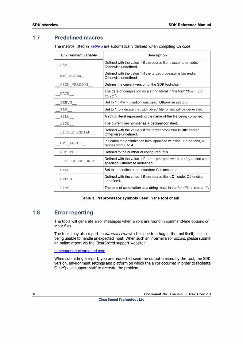
The macros listed in Table 3 are automatically defined when compiling Cn code.
Table 3. Preprocessor symbols used in the tool chain
1.8 Error reporting
The tools will generate error messages when errors are found in command-line options orinput files.
The tools may also report an internal error which is due to a bug in the tool itself, such asbeing unable to handle unexpected input. When such an internal error occurs, please submitan online report via the ClearSpeed support website:
http://support.clearspeed.com
When submitting a report, you are requested send the output created by the tool, the SDKversion, environment settings and platform on which the error occurred in order to facilitateClearSpeed support staff to recreate the problem.
Environment variable Description
__ASM__Defined with the value 1 if the source file is assembler code.
Otherwise undefined.
__BIG_ENDIAN__Defined with the value 1 if the target processor is big endian.
Otherwise undefined.
__CSCN_VERSION__ Defines the current version of the SDK tool-chain.
__DATE__The date of compilation as a string literal in the form "Mmm ddyyyy".
__DEBUG__ Set to 1 if the -g option was used. Otherwise set to 0.
__ELF__ Set to 1 to indicate that ELF object file format will be generated.
__FILE__ A string literal representing the name of the file being compiled.
__LINE__ The current line number as a decimal constant.
__LITTLE_ENDIAN__Defined with the value 1 if the target processor is little endian.
Otherwise undefined.
__OPT_LEVEL__Indicates the optimization level specified with the -On options, n
ranges from 0 to 4.
__NUM_PES__ Defined to the number of configured PEs.
__PREPROCESS_ONLY__Defined with the value 1 if the --preprocess-only option was
specified. Otherwise undefined.
__STDC__ Set to 1 to indicate that standard C is accepted.
__STDCN__Defined with the value 1 if the source file is Cn code. Otherwise
undefined.
__TIME__ The time of compilation as a string literal in the form "hh:mm:ss".

8/9/2019 SDK Reference Manual 3.1 Rev2.B
http://slidepdf.com/reader/full/sdk-reference-manual-31-rev2b 17/204
SDK Reference Manual SDK overview
Document No. 06-RM-1600 Revision: 2.B 17
ClearSpeed Technology Ltd
1.9 Configuration file
All the tools in the SDK make use of a configuration file which holds information about thetarget architecture, as well as specific configuration options for each stage of processing. A
configuration file will be provided for each target architecture. The default search path forconfiguration files is specified with the CSPATH environment variable. The configuration file(target_device.cfg) is normally in the config directory of the SDK installation.
The configuration file is split into a number of sections. Sections are organized in a hierarchywith different levels of the hierarchy delimited by a fullstop in the names of the configurationparameters. Each section contains parameters relevant to a particular aspect of the targetarchitecture or part of the tool chain.
1.10 Licensing and open source components
The SDK tools use the FLEXlm license server to manage the software licenses. You will be
provided with a license key for your copy of the SDK. Information for installing FLEXlm andhow to request a license key can be found in the SDK Installation Guide.
Some tools and the standard C libraries are provided under the GNU General Public Licenseor Lesser General Public License: see the files GPL.html and LGPL.html in the SDK docu-mentation directory for details. The source code for these components is provided as part ofthe SDK installation.

8/9/2019 SDK Reference Manual 3.1 Rev2.B
http://slidepdf.com/reader/full/sdk-reference-manual-31-rev2b 18/204
Building programs SDK Reference Manual
18 Document No. 06-RM-1600 Revision: 2.B
ClearSpeed Technology Ltd
2 Building programs
This chapter describes how to use the cscn command to compile a Cn source code file into
an executable file for ClearSpeed’s CSX processors.
2.1 Hello world
The source of a simple example program isshown in Example 2.1 . This is a parallel (or
hello_world.cn:
#include <stdiop.h>#include <lib_ext.h>
int main(void) { poly int N = get_penum();
printfp("Hello %d\n", N); return 0;}
Example 2.1
poly ) version of the traditional “hello world”program. This will print out the message 96times, once for each processing element.
To compile the program to an executable, usethe following command:
cscn hello_world.cn
This compiles the source and links the objectfile with the standard libraries. The output iswritten to a file called a.csx, by default. Anyerrors in the generation of the executable will be displayed on the terminal.
The resulting executable file can be loaded and run on the processor by using the command:
csrun a.csx
See the [3]: SDK Introductory Programming Manual and the [4]: CSX600 Runtime SoftwareUser Guide , for more information on how to run programs on the processor or simulator.
The name of the output file can be specified with the -o option. For example, the followingcommand will create an executable file called hello_world.csx.
cscn hello_world.cn -o hello_world.csx
2.2 Multiple source files
A similar command can be used to build anexecutable from multiple source files. In this
hello.cn:
#include <stdio.h>
extern char *world;
int main() { printf("Hello %s\n", world); return 0;}
world.cn:
char * world = "world!";
Example 2.2
case, each source file will be compiled and theresulting object files linked to generate theexecutable code. Example 2.2 shows two
source files which together make up a simple(nonparallel or mono) “hello world” program.
To compile the two files into the executablehello.csx, use the following command:
cscn -o hello.csx hello.cnworld.cn
This can be extended to building programsfrom multiple source files, including assem-bler code, as well as object code files and libraries (the standard libraries are included auto-

8/9/2019 SDK Reference Manual 3.1 Rev2.B
http://slidepdf.com/reader/full/sdk-reference-manual-31-rev2b 19/204
SDK Reference Manual Building programs
Document No. 06-RM-1600 Revision: 2.B 19
ClearSpeed Technology Ltd
matically). The cscn command will do the appropriate thing for each file, based on the filename extension.
world.is:
.section .mono.data .align 4world:: .int .LL_1 .global world
.LL_1:: .asciz "world!
Example 2.3
The file in Example 2.3 shows an assemblylanguage equivalent of the code inworld.cn. This can be used to build an exe-cutable with the following command:
cscn -o hello.csx hello.cnworld.is
2.3 Processing performed by cscn
When you invoke cscn, it performs the following series of processing steps to convert thesource code to an executable:
Preprocessing
Compilation
Assembly
Linking
The steps cscn performs are based on the file extension. For more information, seeSection 1.3: File naming conventions on page 14 . Some examples of the processing stagesare as follows:
cscn file.cn – preprocess, compile, assemble and link
cscn file.is – preprocess, assemble and link
cscn file.cso – link
Options are available to allow you to stop this process at any of the intermediate steps. Forexample, the -c option says not to run the linker. The output in this case consists of objectfiles created by the assembler.
The “hello world” code, Example 2.1, could be compiled to an executable with the followingsequence of commands:
cscn -E -o hello_world.csi hello_world.cn preprocess source tohello_world.cn
cscn -S hello_world.csi compile to hello_world.is
(assembly language file)
cscn -c hello_world.is assemble source tohello_world.cso (object code)
cscn hello_world.cso link object code to executable, a.csx
The following sections provide more details of all the command-line options available and theprocessing performed at each step.
8/9/2019 SDK Reference Manual 3.1 Rev2.B
http://slidepdf.com/reader/full/sdk-reference-manual-31-rev2b 20/204
Building programs SDK Reference Manual
20 Document No. 06-RM-1600 Revision: 2.B
ClearSpeed Technology Ltd
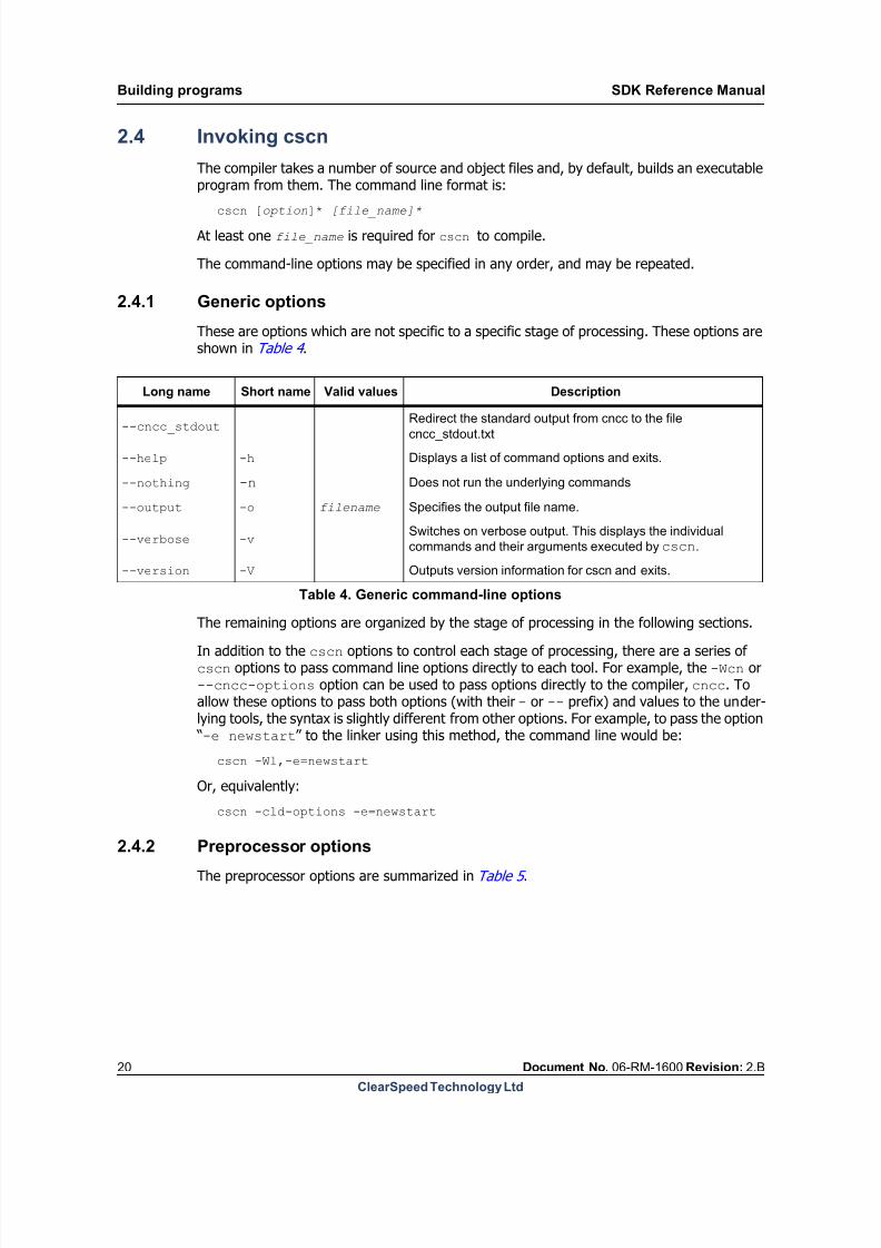
2.4 Invoking cscn
The compiler takes a number of source and object files and, by default, builds an executableprogram from them. The command line format is:
cscn [option]* [file_name]*
At least one file_name is required for cscn to compile.
The command-line options may be specified in any order, and may be repeated.
2.4.1 Generic options
These are options which are not specific to a specific stage of processing. These options areshown in Table 4 .
The remaining options are organized by the stage of processing in the following sections.In addition to the cscn options to control each stage of processing, there are a series ofcscn options to pass command line options directly to each tool. For example, the -Wcn or--cncc-options option can be used to pass options directly to the compiler, cncc. Toallow these options to pass both options (with their - or -- prefix) and values to the under-lying tools, the syntax is slightly different from other options. For example, to pass the option
“-e newstart” to the linker using this method, the command line would be:
cscn -Wl,-e=newstart
Or, equivalently:
cscn -cld-options -e=newstart
2.4.2 Preprocessor options
The preprocessor options are summarized in Table 5 .
Long name Short name Valid values Description
--cncc_stdout Redirect the standard output from cncc to the filecncc_stdout.txt
--help -h Displays a list of command options and exits.
--nothing -n Does not run the underlying commands
--output -o filename Specifies the output file name.
--verbose -vSwitches on verbose output. This displays the individual
commands and their arguments executed by cscn.
--version -V Outputs version information for cscn and exits.
Table 4. Generic command-line options

8/9/2019 SDK Reference Manual 3.1 Rev2.B
http://slidepdf.com/reader/full/sdk-reference-manual-31-rev2b 21/204
SDK Reference Manual Building programs
Document No. 06-RM-1600 Revision: 2.B 21
ClearSpeed Technology Ltd
-Dname[=value]
--define name[=value]
These options define a preprocessor macro called name. The value is optional and defaultsto 1 if omitted. The option can be used multiple times to define more than one macro.
The following example defines macros TRUE and FALSE with the values 1 and 0 respectively:
-DTRUE -DFALSE=0
--define TRUE --define FALSE=0
-I path
--inc-dir path
Adds path to the list of directories to be searched for include files. The default list is spec-ified by the CSINC environment variable. Multiple directories may be specified by using theoption multiple times. The directories will be searched in the order specified.
The following example appends /local/includes to the CSINC include path:
-I/local/includes
--inc-dir /local/includes--no-cpp-comments
By default, the preprocessor will accept both traditional C block comments (/* ... */) andC++ line comments (//...). This option disables the use of C++ style comments.
-P
--no-lines
The preprocessor normally inserts lines in the output file of the form:
# linenumber filename flags
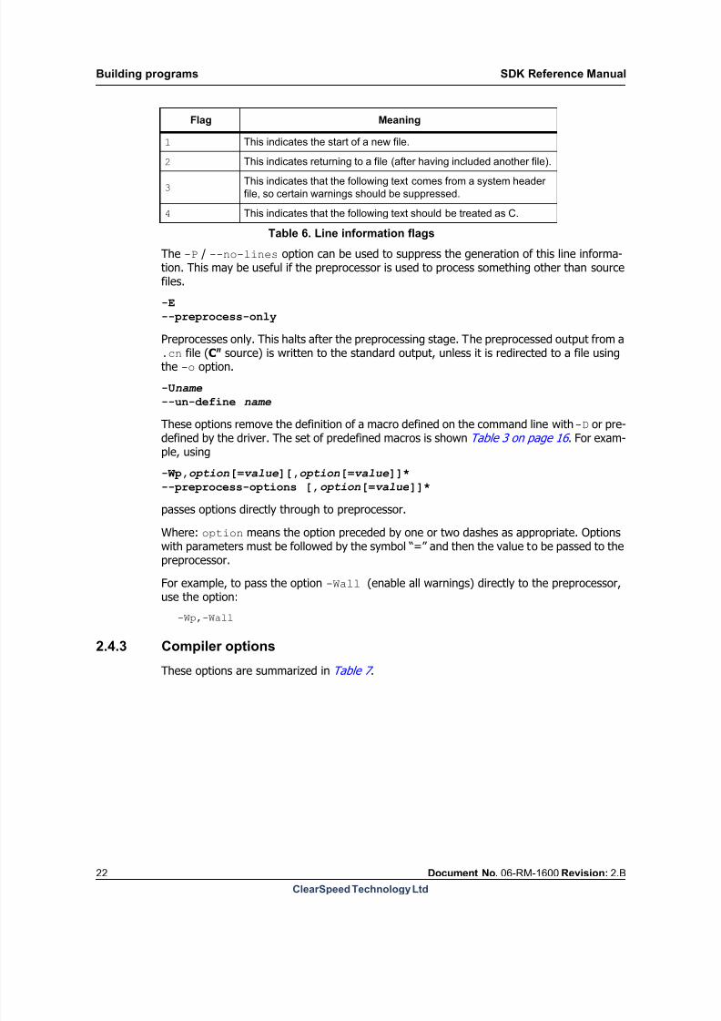
This indicates that the output came from line linenumber in file filename. The file nameis followed by zero or more flags separated by spaces. The flags have the meanings shownin Table 6 .
Long nameShort
nameValid values Description
--define -D name[=value] Define name when preprocessing input.
--inc-dir -I path Add path to the include file search path.
--no-cpp-comments Disallow C++ style line comments.
--no-lines -PDo not produce #line information in
preprocessed output.
--preprocess-only -E Preprocess only: do not compile.
--preprocess-only-comments -CHalts after preprocessing with comments
left in the output.
--preprocess-options -Wp [,option[=value]]*Comma separated list of options to be
passed directly through to preprocessor.
--un-define -U name Undefine a predefined symbol
Table 5. Summary of preprocessor command-line options
8/9/2019 SDK Reference Manual 3.1 Rev2.B
http://slidepdf.com/reader/full/sdk-reference-manual-31-rev2b 22/204
Building programs SDK Reference Manual
22 Document No. 06-RM-1600 Revision: 2.B
ClearSpeed Technology Ltd
The -P / --no-lines option can be used to suppress the generation of this line informa-tion. This may be useful if the preprocessor is used to process something other than sourcefiles.
-E
--preprocess-only
Preprocesses only. This halts after the preprocessing stage. The preprocessed output from a.cn file (Cn source) is written to the standard output, unless it is redirected to a file usingthe -o option.
-Uname
--un-define name
These options remove the definition of a macro defined on the command line with -D or pre-defined by the driver. The set of predefined macros is shown Table 3 on page 16 . For exam-ple, using
-Wp,option[=value][,option[=value]]*
--preprocess-options [,option[=value]]*
passes options directly through to preprocessor.Where: option means the option preceded by one or two dashes as appropriate. Optionswith parameters must be followed by the symbol “=” and then the value to be passed to thepreprocessor.
For example, to pass the option -Wall (enable all warnings) directly to the preprocessor,use the option:
-Wp,-Wall
2.4.3 Compiler options
These options are summarized in Table 7 .
Flag Meaning
1 This indicates the start of a new file.
2 This indicates returning to a file (after having included another file).
3This indicates that the following text comes from a system header
file, so certain warnings should be suppressed.
4 This indicates that the following text should be treated as C.
Table 6. Line information flags

8/9/2019 SDK Reference Manual 3.1 Rev2.B
http://slidepdf.com/reader/full/sdk-reference-manual-31-rev2b 23/204
SDK Reference Manual Building programs
Document No. 06-RM-1600 Revision: 2.B 23
ClearSpeed Technology Ltd
Long nameShort
nameValid values Description
--check-mono-frame-size integer
Set maximum size (in bytes) of the
mono stack frame for all functions(default 64 KB).
--check-poly-frame-size integer
Set maximum size (in bytes) of the
poly stack frame for all functions
(default 3 KB).
--cncc-options -Wcn [,option[=value]]*Comma separated list of options to
be passed directly through to the
compiler.
--compile-only -S Halts after compile stage.
--debug -g Generate debug information.
--dynamic-stack-check
Enables run-time stack checking at
function entry.
--error-mono-frameIssue error when mono frame
checks fail.
--error-poly-frameIssue error when poly frame checks
fail.
--force-mono-align integer Force alignment of mono data.
--inliner-info Output information about function
inlining progress
--inliner-disable Completely switch off function
inlining
--inliner-poly_local_sizeinteger
Maximum size of poly locals in anyfunction to be inlined in bytes
(default: 512)
--inliner-mono_local_sizeinteger
Maximum size of mono locals in any
function to be inlined in bytes
(default: 1024)
--inliner-max_statements
integer
Maximum size of functions to be
inlined counted by statement
(default: 50)
--inliner-auto Enable the compiler to automatically
choose functions to be inlined
(default at O3 and above)
--inliner-noauto Prevent the compiler from
automatically choosing functions to
be inlined
--no-check-ldst-offsetsDisable compile-time checks on
stack-pointer-relative loads/stores.
--check-mono-frameEnable mono stack frame size
checks.
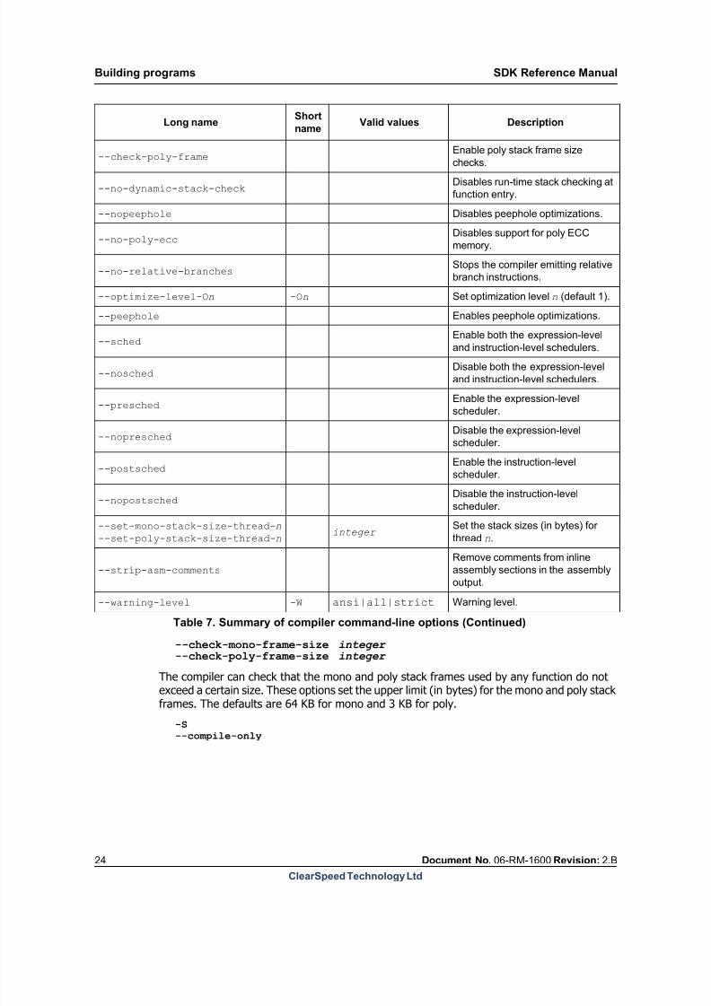
Table 7. Summary of compiler command-line options
8/9/2019 SDK Reference Manual 3.1 Rev2.B
http://slidepdf.com/reader/full/sdk-reference-manual-31-rev2b 24/204
Building programs SDK Reference Manual
24 Document No. 06-RM-1600 Revision: 2.B
ClearSpeed Technology Ltd
--check-mono-frame-size integer --check-poly-frame-size integer
The compiler can check that the mono and poly stack frames used by any function do notexceed a certain size. These options set the upper limit (in bytes) for the mono and poly stackframes. The defaults are 64 KB for mono and 3 KB for poly.
-S
--compile-only
--check-poly-frameEnable poly stack frame size
checks.
--no-dynamic-stack-checkDisables run-time stack checking at
function entry.
--nopeephole Disables peephole optimizations.
--no-poly-eccDisables support for poly ECC
memory.
--no-relative-branchesStops the compiler emitting relative
branch instructions.
--optimize-level-On -On Set optimization level n (default 1).
--peephole Enables peephole optimizations.
--sched Enable both the expression-leveland instruction-level schedulers.
--noschedDisable both the expression-level
and instruction-level schedulers.
--preschedEnable the expression-level
scheduler.
--nopreschedDisable the expression-level
scheduler.
--postschedEnable the instruction-level
scheduler.
--nopostsched
Disable the instruction-level
scheduler.
--set-mono-stack-size-thread-n
--set-poly-stack-size-thread-ninteger
Set the stack sizes (in bytes) for
thread n.
--strip-asm-comments
Remove comments from inline
assembly sections in the assembly
output.
--warning-level -W ansi|all|strict Warning level.
Long nameShort
nameValid values Description
Table 7. Summary of compiler command-line options (Continued)

8/9/2019 SDK Reference Manual 3.1 Rev2.B
http://slidepdf.com/reader/full/sdk-reference-manual-31-rev2b 25/204
SDK Reference Manual Building programs
Document No. 06-RM-1600 Revision: 2.B 25
ClearSpeed Technology Ltd
Preprocesses and compiles only. This halts after the compilation stage. The output is theassembler source code for the compiled code. The assembler code output is written to a filewith the extension .is. The default file name can be changed with the -o option.
-Wcn,option[=value][,option[=value]]*
--cncc-options [,option[=value]]*
Passes options directly through to the compiler. Options with parameters must be followedby the symbol "=" and then the value to be passed to the compiler.
Where: option means the option preceded by one or two dashes as appropriate.
-g
--debug
Causes the compiler and the assembler to include debugging information in the object files.The debugging information is in DWARF 2.0 format (see Section 13.8: Debugging informa- tion format on page 176 for more information). The -g option can be used with optimizedcode although this may produce some unexpected results: some variables may not exist, the
flow of control may be different from expected, some statements may have moved or maynever be executed and so on.
--dynamic-stack-check
Enables run time checking of stack usage on function entry. This adds code to each functionto test that the calculated stack usage of the function does not overrun the available stackspace. If the stack usage is calculated to cause a stack overflow, then a warning messagewill will be issued by the runtime.
This will cause some performance impact and so is not enabled by default.
--error-mono-frame
--error-poly-frame
By default, the compiler issues a warning if the stack frame exceeds the specified maximumsize. These options causes the compiler to treat this as an error. The maximum stack framesize can be set with the check-mono-frame-size and check-mono-frame-size options.
--force-mono-align integer
Causes the compiler to force the alignment of all mono data to the specified alignment. Youcan override this option with the use of specific alignment pragmas, See Section 11.10: Prag- mas on page 125 .
--no-check-ldst-offsets
Disables internal checks on stack-pointer-relative loads and stores.
The compiler normally performs compile-time checks on these instructions to try and detectif you are likely to run off the end of the allocated space within a function.
Since this has no performance penalty, being compile-time rather than runtime checking, itis always enabled by default.
--check-mono-frame
--check-poly-frame
Enables the compile-time stack frame checks. If a function’s stack frame exceeds the speci-fied limit, then a warning message will be displayed.

8/9/2019 SDK Reference Manual 3.1 Rev2.B
http://slidepdf.com/reader/full/sdk-reference-manual-31-rev2b 26/204

8/9/2019 SDK Reference Manual 3.1 Rev2.B
http://slidepdf.com/reader/full/sdk-reference-manual-31-rev2b 27/204
SDK Reference Manual Building programs
Document No. 06-RM-1600 Revision: 2.B 27
ClearSpeed Technology Ltd
this thread. If you use any other threads in your program then you must allocate mono andpoly stacks for each thread. See Section 12.1: Stack allocation on page 150 for more infor-mation.
--strip-asm-comments
Removes comments from inline assembly sections in the assembly output.
-W ansi | strict | all
--warning-level ansi | strict | all
This option controls the types of warning messages generated by the compiler. The defaultis a low level of warnings that includes most, but not all, of the ANSI C warnings. Extra warn-ings can be enabled as shown in Table 8 .
ansi
strictall
2.4.4 Assembler options
These options are summarized in Table 9 .
[,option[=value]]*
-c
--compile-assemble-only
Preprocesses, compiles and assembles only. This halts after the assembly stage. The outputis an object file ready for linking. The object code output is written to a file with the extension.cso. The default file name can be changed with the -o option.
-g
--debug
Makes the compiler and the assembler include debugging information in the object files. Thedebugging information is in DWARF 2.0 format (see Section 13.8: Debugging informationformat on page 176 for more information). The -g option can be used with optimized codealthough this may produce some unexpected results: some variables may not exist, the flow
Level Warnings enabled
Enables generation of ANSI C warnings.
Enables generation of strict warnings.Enables generation of both ANSI and strict warnings.
Table 8. Compiler warning levels
Long nameShort
nameValid values Description
--compile-assemble-only -c Halts after the assembly stage.
--debug -g Generates debugging information.
--mist-file -m
Specifies a file containing extra
instruction definitions. May be
specified more than once.
--mass-options -Wa
Comma separated list of options to
be passed directly through to the
assembler.
Table 9. Summary of assembler command-line options
8/9/2019 SDK Reference Manual 3.1 Rev2.B
http://slidepdf.com/reader/full/sdk-reference-manual-31-rev2b 28/204
Building programs SDK Reference Manual
28 Document No. 06-RM-1600 Revision: 2.B
ClearSpeed Technology Ltd
of control may be different from expected, some statements may have moved or may neverbe executed and so on.
-m file_name
--mist-file file_nam e
The assembler uses a macro language to define the instruction set. The standard instructionset definition file is called iset.mst. This option can be used to extend the instruction setby specifying a file containing further instruction definitions.
-Wa,option[=value][,o ption[=value]]*
--mass-options [,option[=value]]*
Passes options directly through to the assembler. Options with parameters must be followedby the symbol “=” and then the value to be passed to the assembler.
Where: option means the option preceded by one or two dashes as appropriate.
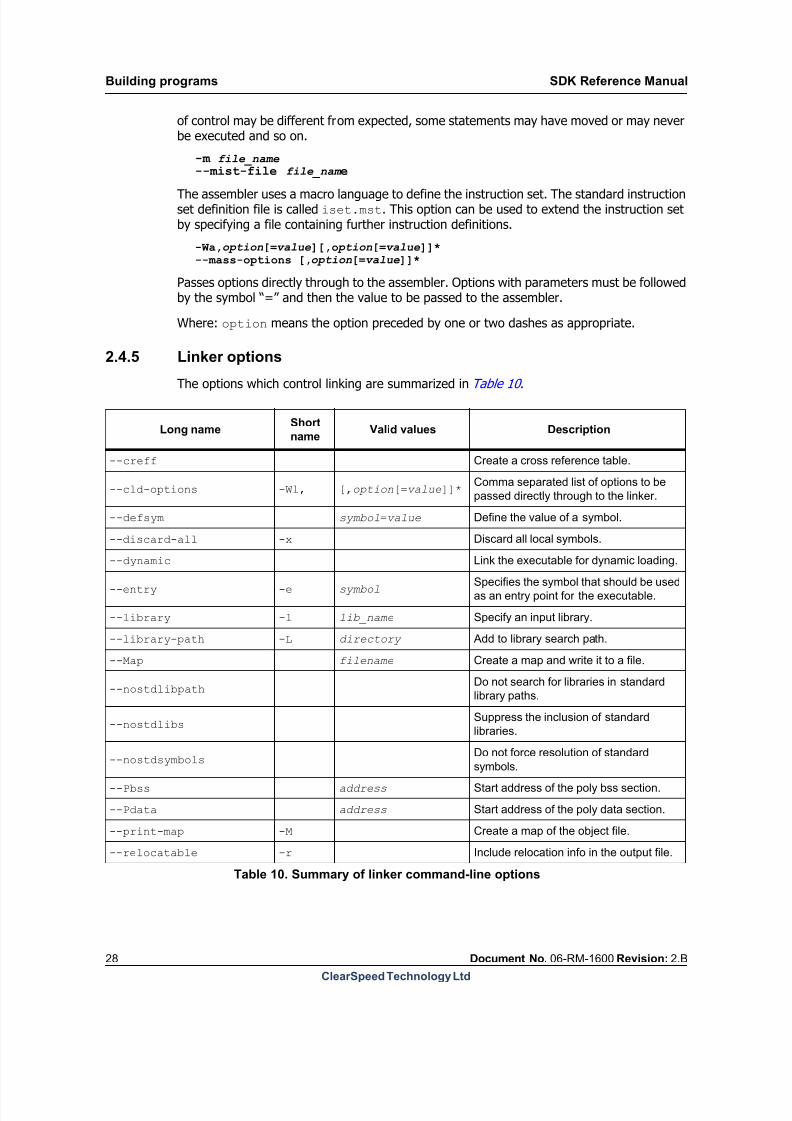
2.4.5 Linker options
The options which control linking are summarized in Table 10 .
Long nameShort
nameValid values Description
--creff Create a cross reference table.
--cld-options -Wl, [,option[=value]]*Comma separated list of options to be
passed directly through to the linker.
--defsym symbol=value Define the value of a symbol.
--discard-all -x Discard all local symbols.
--dynamic Link the executable for dynamic loading.
--entry -e symbolSpecifies the symbol that should be used
as an entry point for the executable.
--library -l lib_name Specify an input library.
--library-path -L directory Add to library search path.
--Map filename Create a map and write it to a file.
--nostdlibpathDo not search for libraries in standard
library paths.
--nostdlibsSuppress the inclusion of standard
libraries.
--nostdsymbols Do not force resolution of standardsymbols.
--Pbss address Start address of the poly bss section.
--Pdata address Start address of the poly data section.
--print-map -M Create a map of the object file.
--relocatable -r Include relocation info in the output file.
Table 10. Summary of linker command-line options

8/9/2019 SDK Reference Manual 3.1 Rev2.B
http://slidepdf.com/reader/full/sdk-reference-manual-31-rev2b 29/204
SDK Reference Manual Building programs
Document No. 06-RM-1600 Revision: 2.B 29
ClearSpeed Technology Ltd
-Wl,option[=value][,option[=value]]*
--cld-options [,o ption[=value]]*
Passes options directly through to linker. Options with parameters must be followed by thesymbol “=” and then the value to be passed to the linker.
Where: option means the option preceded by one or two dashes as appropriate.
Category: files and paths
-llibrary
--library library
Defines an input library file name. By convention, the linker converts the library name spec-ified into a file name by prepending lib to the name and appending the file extension .csa.This file name is then looked for in the library search path. The default search path is thecurrent directory and any paths specified in the CSLIB environment variable.
--restrict chip-index
Restrict the memory available to the
linker to that associated with a specified
chip.
--static
Lays out the memory for the CSX
statically using a linker script present in
the path.
--strip-all -sDo not include the symbol table in the
output file.
--strip-debug -dDo not include the debug info in the
output file.
--Tbss address Start address of the mono bss section.
--Tdata address Start address of the mono data section.
--trace-symbol -y symbol_name Print references to the given symbol.
--Ttext address Start address of the text section.
--use-script [filename] Allows the user to link statically using a
hand crafted linker script file(a)
a. The linker script is straight forward and is similar to ld linker scripts for memory layout.
They each have the form:
MEMORY
{
monodram : ORIGIN = 0x80000000, LENGTH = 512M
monosram : ORIGIN = 0x02000000, LENGTH = 128K
polyram : ORIGIN = 0x0, LENGTH = 6K
noload : ORIGIN = 0x0, LENGTH = 512M
}
with the sizes filled in correctly for the different ranges.
Long nameShort
nameValid values Description
Table 10. Summary of linker command-line options (Continued)

8/9/2019 SDK Reference Manual 3.1 Rev2.B
http://slidepdf.com/reader/full/sdk-reference-manual-31-rev2b 30/204
Building programs SDK Reference Manual
30 Document No. 06-RM-1600 Revision: 2.B
ClearSpeed Technology Ltd
For example, the command:
cscn hello.cn -lworld
will look for a library file called libworld.csa in the standard library search path.
Note: It is also possible to specify the full library name as an argument as if it were a regularobject file. In this case, the library search is limited to the current directory.
This options can be used multiple times to link multiple libraries.
Some libraries are included automatically (see the description of the --nostdlibs optionbelow for details).
-Ldir
--library-path dir
Adds a directory to the library search path. This option can be used multiple times to addmore than one directory to the search path. The default library search path is the currentdirectory and any paths specified in the CSLIB environment variable.
Libraries specified with the -l option will be searched for in the default path and then thepaths specified with the -L option. The search will commence with the current directory andcontinue in the order in which the directories appear on the command line.
To support differing conventions on different operating systems, both forward and backslashes are supported as directory separators in the path. The path can finish with a trailingslash. If this slash is omitted, one is appended to the path.
For example, the following command will search for the library libworld.csa in the stan-dard search path and in the directory libs:
cscn hello.cn -lworld -Llibs--nostdlibpath
Forces the linker to ignore the default library search paths specified in the CSLIB environ-ment variable.
--nostdlibs
Suppresses the inclusion of standard libraries. The libraries to be automatically scanned forsymbols by the linker can be specified in the SDK configuration file.
The standard libraries are cn, cn_poly, and cn_ext. This option ignores those librariesunless they are explicitly named with the -l option as shown in the example below.
cscn --nostdlibs -lcn -lcn_poly -lcn_ext hello.cn
Category: file layout
-e entry_symbol
--entry entry_symbol
Forces the linker to use the symbol entry_symbol as the entry point. The default entrypoint for programs is _start.
--Pbss address
8/9/2019 SDK Reference Manual 3.1 Rev2.B
http://slidepdf.com/reader/full/sdk-reference-manual-31-rev2b 31/204
SDK Reference Manual Building programs
Document No. 06-RM-1600 Revision: 2.B 31
ClearSpeed Technology Ltd
Sets the start address of the .poly.bss section. address is a numeric value. Both decimaland hexadecimal formats are supported. A hexadecimal value is specified using C syntax.
--Pbss 0x1000--Pdata address
Sets the start address of the .poly.data section. address is a numeric value. Both deci-mal and hexadecimal formats are supported. A hexadecimal value is specified using C syntax.
--Pdata 0x800--restrict chip-index
Restricts memory resources visible to the linker to a selected chip. The chip index is zerobased. For example, to restrict the memory resources of a particular CSX executable to thefirst chip the following option would be used:
--restrict 0
--Tdata address
Sets the start address of the .mono.data section. address is a numeric value. Both deci-
mal and hexadecimal formats are supported. A hexadecimal value is specified using C syntax.

8/9/2019 SDK Reference Manual 3.1 Rev2.B
http://slidepdf.com/reader/full/sdk-reference-manual-31-rev2b 32/204
Building programs SDK Reference Manual
32 Document No. 06-RM-1600 Revision: 2.B
ClearSpeed Technology Ltd
--Tdata 0x0a000000--Ttext address
Sets the start address of the .text section. address is a numeric value. Both decimal andhexadecimal formats are supported. A hexadecimal value is specified using C syntax.
--Ttext 0x80000000
--Tbss address
Sets the start address of the .mono.bss section. address is a numeric value. Both decimaland hexadecimal formats are supported. A hexadecimal value is specified using C syntax.
--Tbss 0x02000000
Category: map
-M
--print-map
Generates a map of the object file and prints it to standard output. The map details layoutof sections, segments and symbols in the executable image as well as the physical file. Theinformation is presented in two formats: one for sections and segments, and one for symbols,see Figure 2 .
+-----------------------------------------------------------------------
| Sections: file_offset[size] virt_address[size] section_name type
+-----------------------------------------------------------------------
| Segments: file_offset[size] virt_address[size] segment_name type
+---------------------------------------------------------------------| Symbols: address symbol_name section_name module_name
Figure 2.Contents of linker map
Here the file_offset[size] pair represents the file location of the given section or seg-ment in the csx file. The virt_address[size] pair gives the location of the section orsegment as it will be loaded in the device memory. The type field says whether the sectionor segment is loadable into mono or poly memory space of the device or whether it is purelydata that is stored in the object file. The valid values are: MONO_LOAD, POLY_LOAD andUNDEF.
The symbol information consists of a relocated address, symbol name, section name in whichthe symbol has been defined and the module name which supplied the definition. If the sym-bol was defined in the user file, the name with extension will be given. If the symbol comes
from the library, the library name without the prefix or a suffix will be printed. For instance,if the full library name were libdbg.csa, the module_name shown will be dbg.
--Map filename
Generates a map and writes it to a file. The format of the map file is as described above.

8/9/2019 SDK Reference Manual 3.1 Rev2.B
http://slidepdf.com/reader/full/sdk-reference-manual-31-rev2b 33/204
SDK Reference Manual Building programs
Document No. 06-RM-1600 Revision: 2.B 33
ClearSpeed Technology Ltd
Category: symbols
--creff
Generates a cross-reference table. The cross-reference table lists symbols, the definitions of
which have been found, and details all locations where the symbols have been referenced.By default, the cross-reference table is printed to standard output. If the --Map option isalso specified, the table is appended to the map file.
The format of the cross-reference table is shown in Figure 3 .
+-----------------------------------------------------------------------| X reference: sym_name in module_name:section_name @ addr_org [relocated ]| ref_in_module @ addr_org [relocated ]
Figure 3.Format of cross-reference table
The first line displays the symbol name, module (file) name, and the section name in which
the symbol was defined. Also, the address pair is given that specifies this location. Theaddr_org field is an address relative to the start of the section before relocation (always 0).The relocated field reflects the actual placement of the sections in the executable imageand is the true address where the symbol can be found in the relevant domain (mono or poly)of the address space of the device.
This line is followed by zero or more lines, which contain the module name and the addresspair describing the location where the symbol has been referenced.
--defsym name=value
Sets the value of a symbol. name is a string, value an integer given in decimal or hexadec-imal format. If the symbol was external, it is redefined to be global. This option can be usedmultiple times to define multiple symbols.
--defsym start_address=0x00400000
This defines an absolute symbol. That is, it specifies the final value of the symbol after linking(see section Section 14.3.2: Symbols for more information about symbol types).
--dynamic
Links the executable for dynamic loading.
--nostdsymbols
It is possible to specify symbols in the configuration file that the linker will treat as externalsymbols to be resolved, even if they were never explicitly referenced in the code. This is use-ful for forcing special libraries, such as the bootstrap or prologue/epilogue code, to be
included with the executable.
This option switches off this default linker behavior.
-r
--relocatable
Makes the output file relocatable. All relocation information will be included in the output file.
-s
--strip-all

8/9/2019 SDK Reference Manual 3.1 Rev2.B
http://slidepdf.com/reader/full/sdk-reference-manual-31-rev2b 34/204
Building programs SDK Reference Manual
34 Document No. 06-RM-1600 Revision: 2.B
ClearSpeed Technology Ltd
Omits all symbol information from the output file.
-d
--strip-debug
Omits debugger symbol information (but not all symbols) from the output file.
-x
--discard-all
Omits all local symbol information from the output file. Similar to -s but global symbols areleft in the output file.
-y symbol_name
--trace-symbol symbol_name
Causes the specified symbol to be traced . Each reference to the chosen symbol will bereported (together with a module name and local address). This option can be specified mul-tiple times to trace multiple symbols. If the --Map option was specified as well, the symboltrace information is appended to the map file.
The format in which the information is presented is analogous to the --creff option.
8/9/2019 SDK Reference Manual 3.1 Rev2.B
http://slidepdf.com/reader/full/sdk-reference-manual-31-rev2b 35/204
SDK Reference Manual The preprocessor
Document No. 06-RM-1600 Revision: 2.B 35
ClearSpeed Technology Ltd
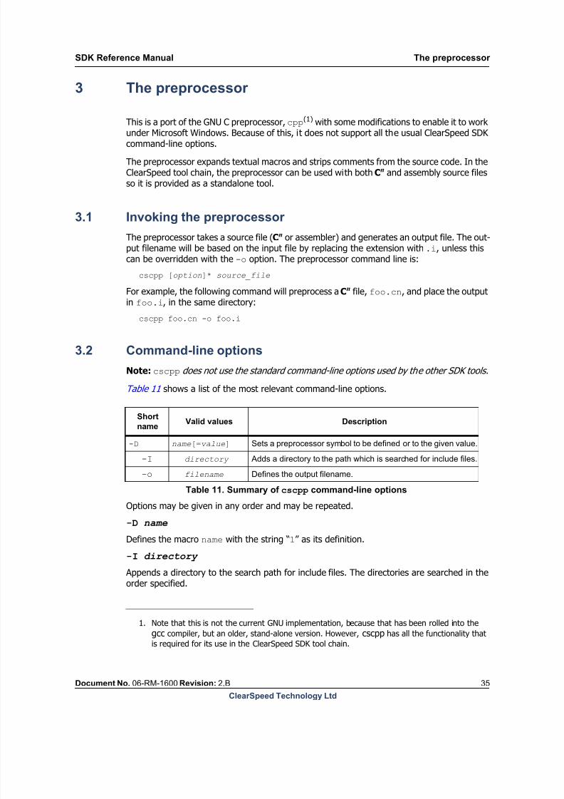
3 The preprocessor
This is a port of the GNU C preprocessor, cpp(1) with some modifications to enable it to work
under Microsoft Windows. Because of this, it does not support all the usual ClearSpeed SDKcommand-line options.
The preprocessor expands textual macros and strips comments from the source code. In theClearSpeed tool chain, the preprocessor can be used with both Cn and assembly source filesso it is provided as a standalone tool.
3.1 Invoking the preprocessor
The preprocessor takes a source file (Cn or assembler) and generates an output file. The out-put filename will be based on the input file by replacing the extension with .i, unless thiscan be overridden with the -o option. The preprocessor command line is:
cscpp [option]* source_file
For example, the following command will preprocess a Cn file, foo.cn, and place the outputin foo.i, in the same directory:
cscpp foo.cn -o foo.i
3.2 Command-line options
Note: cscpp does not use the standard command-line options used by the other SDK tools.
Table 11 shows a list of the most relevant command-line options.
-I directory
-o filename
Options may be given in any order and may be repeated.
-D name
Defines the macro name with the string “1” as its definition.
-I directory
Appends a directory to the search path for include files. The directories are searched in theorder specified.
1. Note that this is not the current GNU implementation, because that has been rolled into the
gcc compiler, but an older, stand-alone version. However, cscpp has all the functionality thatis required for its use in the ClearSpeed SDK tool chain.
Short
nameValid values Description
-D name[=value] Sets a preprocessor symbol to be defined or to the given value.
Adds a directory to the path which is searched for include files.
Defines the output filename.
Table 11. Summary of cscpp command-line options

8/9/2019 SDK Reference Manual 3.1 Rev2.B
http://slidepdf.com/reader/full/sdk-reference-manual-31-rev2b 36/204
The preprocessor SDK Reference Manual
36 Document No. 06-RM-1600 Revision: 2.B
ClearSpeed Technology Ltd
-o filename
Specifies the output file. Conventionally, the suffix .i is used for preprocessed files.
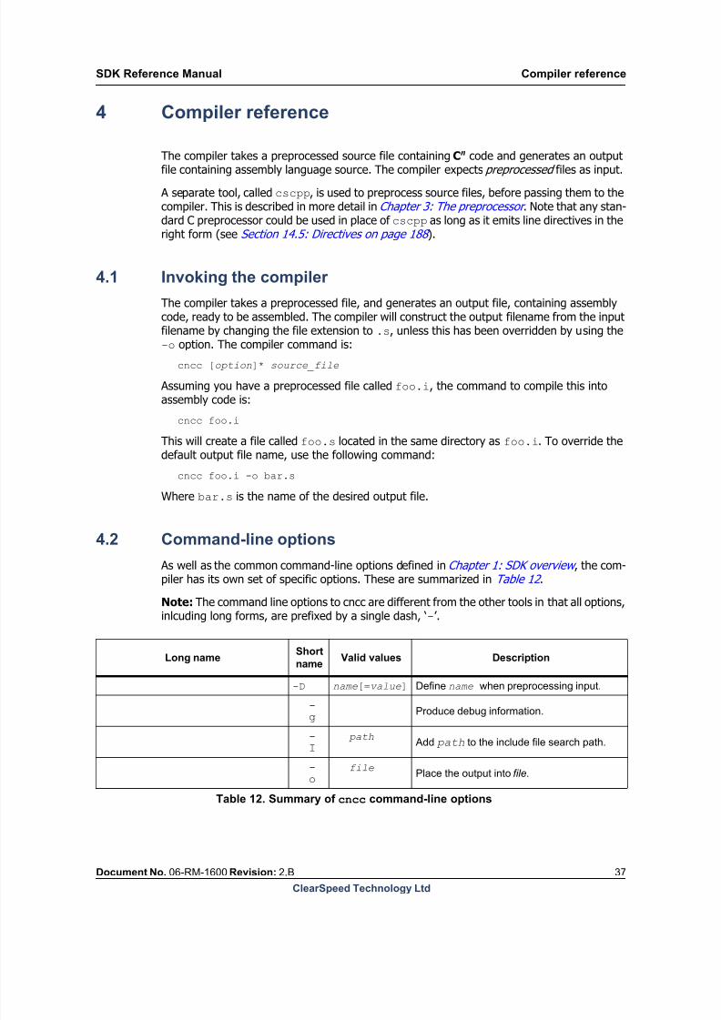
8/9/2019 SDK Reference Manual 3.1 Rev2.B
http://slidepdf.com/reader/full/sdk-reference-manual-31-rev2b 37/204
SDK Reference Manual Compiler reference
Document No. 06-RM-1600 Revision: 2.B 37
ClearSpeed Technology Ltd
4 Compiler reference
The compiler takes a preprocessed source file containing Cn code and generates an output
file containing assembly language source. The compiler expects preprocessed files as input.
A separate tool, called cscpp, is used to preprocess source files, before passing them to thecompiler. This is described in more detail in Chapter 3: The preprocessor . Note that any stan-dard C preprocessor could be used in place of cscpp as long as it emits line directives in theright form (see Section 14.5: Directives on page 188 ).
4.1 Invoking the compiler
The compiler takes a preprocessed file, and generates an output file, containing assemblycode, ready to be assembled. The compiler will construct the output filename from the inputfilename by changing the file extension to .s, unless this has been overridden by using the-o option. The compiler command is:
cncc [option]* source_file
Assuming you have a preprocessed file called foo.i, the command to compile this intoassembly code is:
cncc foo.i
This will create a file called foo.s located in the same directory as foo.i. To override thedefault output file name, use the following command:
cncc foo.i -o bar.s
Where bar.s is the name of the desired output file.
4.2 Command-line options
As well as the common command-line options defined in Chapter 1: SDK overview , the com-piler has its own set of specific options. These are summarized in Table 12 .
Note: The command line options to cncc are different from the other tools in that all options,inlcuding long forms, are prefixed by a single dash, ‘-’.
Long nameShort
nameValid values Description
-D name[=value] Define name when preprocessing input.
-g
Produce debug information.
-I
path Add path to the include file search path.
-o
filePlace the output into file.
Table 12. Summary of cncc command-line options
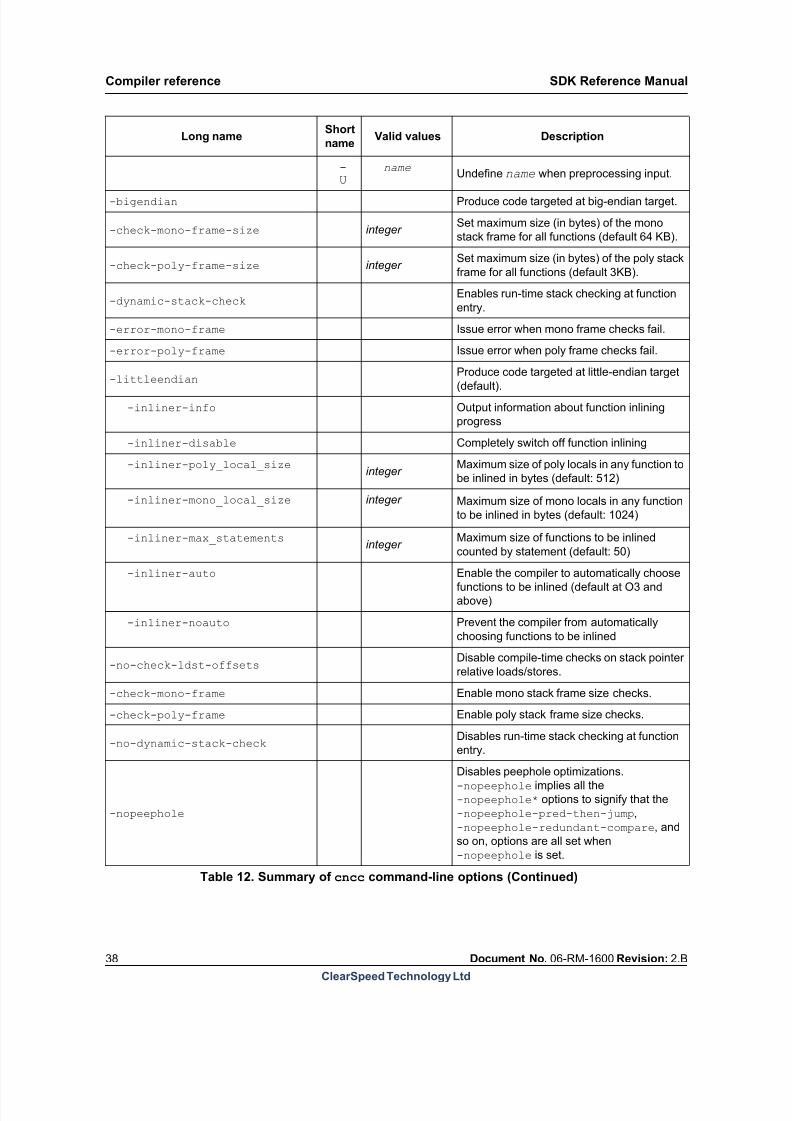
8/9/2019 SDK Reference Manual 3.1 Rev2.B
http://slidepdf.com/reader/full/sdk-reference-manual-31-rev2b 38/204
Compiler reference SDK Reference Manual
38 Document No. 06-RM-1600 Revision: 2.B
ClearSpeed Technology Ltd
-U
nameUndefine name when preprocessing input.
-bigendian Produce code targeted at big-endian target.
-check-mono-frame-size integer Set maximum size (in bytes) of the mono
stack frame for all functions (default 64 KB).
-check-poly-frame-size integer Set maximum size (in bytes) of the poly stack
frame for all functions (default 3KB).
-dynamic-stack-checkEnables run-time stack checking at function
entry.
-error-mono-frame Issue error when mono frame checks fail.
-error-poly-frame Issue error when poly frame checks fail.
-littleendian Produce code targeted at little-endian target(default).
-inliner-info Output information about function inlining
progress
-inliner-disable Completely switch off function inlining
-inliner-poly_local_sizeinteger
Maximum size of poly locals in any function to
be inlined in bytes (default: 512)
-inliner-mono_local_size integer Maximum size of mono locals in any function
to be inlined in bytes (default: 1024)
-inliner-max_statementsinteger
Maximum size of functions to be inlined
counted by statement (default: 50)
-inliner-auto Enable the compiler to automatically choose
functions to be inlined (default at O3 and
above)
-inliner-noauto Prevent the compiler from automatically
choosing functions to be inlined
-no-check-ldst-offsetsDisable compile-time checks on stack pointer
relative loads/stores.
-check-mono-frame Enable mono stack frame size checks.
-check-poly-frame Enable poly stack frame size checks.
-no-dynamic-stack-checkDisables run-time stack checking at function
entry.
-nopeephole
Disables peephole optimizations.
-nopeephole implies all the
-nopeephole* options to signify that the
-nopeephole-pred-then-jump,
-nopeephole-redundant-compare, and
so on, options are all set when
-nopeephole is set.
Long nameShort
nameValid values Description
Table 12. Summary of cncc command-line options (Continued)

8/9/2019 SDK Reference Manual 3.1 Rev2.B
http://slidepdf.com/reader/full/sdk-reference-manual-31-rev2b 39/204
SDK Reference Manual Compiler reference
Document No. 06-RM-1600 Revision: 2.B 39
ClearSpeed Technology Ltd
The command-line options may be specified in any order, and may be repeated.
-D name
-D name=value
Define name when preprocessing the source file. The value is optional and defaults to zeroif not specified.
-g
This option causes the compiler to include debugging information in the output file.
-I path
Add path to the list of directories to be searched for include files. Multiple directories maybe specified by using the -I option multiple times.
-o file
-nopeephole-redundant-compareDisables removal of redundant comparisons
with zero following an arithmetic operation.
-nopeephole-pred-then-jump
Disables merging of predicate-movement
instructions with subsequent jump
instructions.
-nopeephole-mono-stack-changesDisables merging of back-to-back decreases
and increases in the mono stack pointer.
-nopeephole-poly-stack-changesDisables merging of back-to-back decreases
and increases in the poly stack pointer
-nopeephole-combine-ldstDisables merging of stack-pointer-relative
loads and stores to the largest possible sizes.
-peephole Enables peephole optimizations.
-no-poly-ecc Disables support for poly ECC memory.
-no-relative-branchesStops the compiler emitting relative branch
instructions.
-set-mono-stack-size-thread-n
-set-poly-stack-size-thread-ninteger Set the stack sizes (in bytes) for thread n.
-schedEnable both the expression-level and
instruction-level schedulers.
-noschedDisable both the expression-level and
instruction-level schedulers.
-presched Enable the expression-level scheduler.
-nopresched Disable the expression-level scheduler.
-postsched Enable the instruction-level scheduler.
-nopostsched Disable the instruction-level scheduler.
Long nameShort
nameValid values Description
Table 12. Summary of cncc command-line options (Continued)

8/9/2019 SDK Reference Manual 3.1 Rev2.B
http://slidepdf.com/reader/full/sdk-reference-manual-31-rev2b 40/204
8/9/2019 SDK Reference Manual 3.1 Rev2.B
http://slidepdf.com/reader/full/sdk-reference-manual-31-rev2b 41/204
SDK Reference Manual Compiler reference
Document No. 06-RM-1600 Revision: 2.B 41
ClearSpeed Technology Ltd
Enable or disable peephole optimizations. This will replace sequences of instructions withless-expensive versions which have the same effect.
-no-poly-ecc
Produce code assuming that the poly memory has no ECC support. This allows using 1-bytepoly stores with no read-modify-write, which are otherwise disallowed when ECC is enabled.Setting this option can improve performance on architectures where poly memory does nothave ECC enabled.
-set-mono-stack-size-thread-n size-set-poly-stack-size-thread-n size
These options specify the stack size to be used by a thread: n is the thread number that thestack is being defined for and size is the size of the stack in bytes.
Stacks are automatically created for the main execution thread (thread 0). Thread 7 is usedby the asynchronous memcpy functions: mono and poly stacks of zero size are allocated forthis thread. If you use any other threads in your program then you must allocate mono and
poly stacks for each thread. See Section 12.1: Stack allocation on page 150 for more infor-mation.
-sched
-nosched
-presched -nopresched -postsched -nopostsched
These options enable and disable the two phases of the scheduler in the compiler; the pre-scheduler (expression-level scheduler) and post-scheduler (instruction-level scheduler).
Attempts are made to rearrange expressions or instructions (depending on the schedulerphase) to a more optimal ordering, increasing overlap between load/store and computeinstructions. The latencies of instructions are used to find the most optimal sequence. Theallowed reordering is determined by the dependencies between statements or instructions.
The scheduler will not schedule around control-flow, for example function calls, returns,branches, and so on. Only straight-line code in a single basic-block gets scheduled. This alsomeans that the larger a single basic block is, the greater the possibilities open to the sched-uler for moving instructions around.
Instructions in inline assembly code are not reordered by the scheduler, however otherinstructions can be moved around the inline assembly code. The correct setting of constraintson inline assembly code is very important to ensure that the scheduler has enough informa-tion about a block. Without sufficient information the scheduler may move instructions beforeor after inline assembly blocks in an invalid manner. As stated in Section 11.11.4: Constraintdirectives on page 131 , the default is that a .barrier constraint is applied so that nothingis allowed to move across an inline assembly block unless explicitly enabled by the program-mer (using .nobarrier).
4.3 Function inlining
Function inlining is where a function or procedure call statement is replaced by the code thatcomprises the body of the called function. This can be done where the code that containsthe function call is compiled in the presence of the definition of the called function. Refer-ences within the body of the inlined function to the parameters of the function are substituted

8/9/2019 SDK Reference Manual 3.1 Rev2.B
http://slidepdf.com/reader/full/sdk-reference-manual-31-rev2b 42/204
Compiler reference SDK Reference Manual
42 Document No. 06-RM-1600 Revision: 2.B
ClearSpeed Technology Ltd
with the corresponding arguments that were given in the function call. Similarly, returnstatements that return a value within the body of the inlined function are replaced by assign-ments to the object that was assigned to by the original function call statement.
The major benefit of this optimization is to completely eliminate function call overhead and
thereby speed up the execution of the code. Inlining may also allow the compiler to optimizethe code more effectively when the barrier of a function call is removed. Overly aggressiveuse of function inlining can, however, result in undesired code bloat and in some circum-stances may cause poorer performance by negatively impacting the use of the instructioncache.
4.3.1 Conditions on inlining
There is a pragma available to force the compiler to always inline a function (see below), butunless this is used, the compiler always has the option of not inlining a function, whateveroptions, pragmas or keywords are specified. The compiler contains rules to determinewhether it makes sense for a function to be inlined. The information about a function that
is taken into account is the size of the function (in terms of the number of statements thefunction contains) and the number of local variables the function has, which impacts thepotential register pressure within the calling function as well as the stack usage of the caller.By default, the compiler will not inline a function that has over 50 statements in its body, orwhich has more than 512 bytes of poly local variables, or more than 1024 bytes of mono localvariables. These limits can be changed via the compiler command-line options listed inTable 13 . There are a number of other reasons why a function may not be inlined, these are:
Variable argument (varargs) functions
Recursive functions
Use of computed gotos
If the --inliner-info command line option is given to cscn, the compiler will indicate
the reasons why a function has not been inlined.
The optimization level at which inlining is first enabled is -O0.
Note: Function inlining is enabled at all levels of optimization (including no optimization, -O0) in order to allow the consistent compilation of functions that take vector-type argumentsand/or return a vector type. Passing or returning vector types is, at present, not permittedby the ABI (see Chapter 13: Application binary interface on page 157 ). The only way suchfunctions can be used is by forcing inlining of the functions (by using the forceinline pragma).
4.3.2 User controls
As noted above, inlining is an optimization that should be used with care as there is the pos-
sibility that it will degrade performance. At levels of optimization below -O3, inlining willonly occur if you indicate that a certain function should be inlined via the use of the inlinekeyword or inlining pragmas. At -O3 and above, the compiler will undertake to automaticallyinline functions that it evaluates it to be advantageous to do so. The evaluation of the func-tions to be inlined is based on the above rules.

8/9/2019 SDK Reference Manual 3.1 Rev2.B
http://slidepdf.com/reader/full/sdk-reference-manual-31-rev2b 43/204
SDK Reference Manual Compiler reference
Document No. 06-RM-1600 Revision: 2.B 43
ClearSpeed Technology Ltd
Keywords to control inlining
Use of the ‘inline’ keyword is consistent with the C99 specification. The keyword is placedon the function declaration as follows:
inline int compute(int x, float y){
return x + (int)y;
}
According to C99, such a declaration is only used for inlining; the function will not appear inits own right in the generated code as an externally visible symbol. If the function is requiredto be available to be called against from other compiled modules, the function must be sep-arately declared without the inline keyword, in a different Cn file. It is also possible thatdespite the use of the keyword, the function will not be inlined (if the function does not meetthe conditions described above), in which case a separate, noninline, copy of the functionmust be available in a compiled module to prevent a build error.
An inline pragma can be used; functions marked with the pragma are not subject to the C99constraints on inlining.
Compiler options to control inlining
Table 13 shows a set of command-line options for control inlining.
--inliner-info
--inliner-disable
--inliner-poly_local_size
--inliner-mono_local_size
--inliner-max_statements
--inliner-auto
--inliner-noauto
Pragmas to control inlining
#pragma inline
This pragma should be placed immediately before the definition of a function. It is a requestfor the following function to be inlined, but doesn’t guarantee inlining. The behavior whenmarking functions for inlining using this pragma is not the same as when the inline keywordis used. Using the inline pragma does not affect whether or not a function is generated inits own right. This does mean, however, that you may need to use the static keyword to
Long nameValid
valuesDescription
Output information about function inlining progress
Completely switch off function inlining
integer Maximum size of poly locals in any function to be inlined inbytes (default: 512)
integer Maximum size of mono locals in any function to be inlined in
bytes (default: 1024)
integer Maximum size of functions to be inlined counted by
statement (default: 50)
Enable the compiler to automatically choose functions to be
inlined (default at -O3 and above)
Prevent the compiler from automatically choosing functions
to be inlined
Table 13. Summary of inliner command-line options
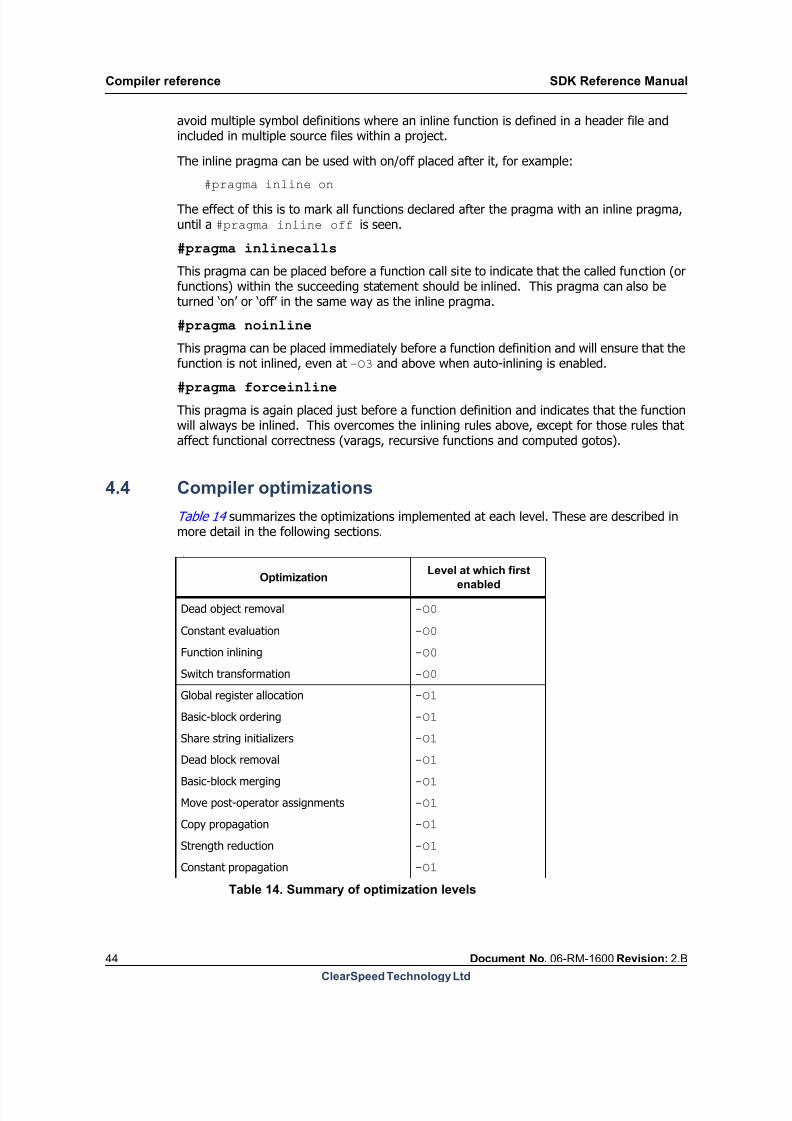
8/9/2019 SDK Reference Manual 3.1 Rev2.B
http://slidepdf.com/reader/full/sdk-reference-manual-31-rev2b 44/204
Compiler reference SDK Reference Manual
44 Document No. 06-RM-1600 Revision: 2.B
ClearSpeed Technology Ltd
avoid multiple symbol definitions where an inline function is defined in a header file andincluded in multiple source files within a project.
The inline pragma can be used with on/off placed after it, for example:
#pragma inline on
The effect of this is to mark all functions declared after the pragma with an inline pragma,until a #pragma inline off is seen.
#pragma inlinecalls
This pragma can be placed before a function call site to indicate that the called function (orfunctions) within the succeeding statement should be inlined. This pragma can also beturned ‘on’ or ‘off’ in the same way as the inline pragma.
#pragma noinline
This pragma can be placed immediately before a function definition and will ensure that thefunction is not inlined, even at –O3 and above when auto-inlining is enabled.
#pragma forceinline
This pragma is again placed just before a function definition and indicates that the functionwill always be inlined. This overcomes the inlining rules above, except for those rules thataffect functional correctness (varags, recursive functions and computed gotos).
4.4 Compiler optimizations
Table 14 summarizes the optimizations implemented at each level. These are described inmore detail in the following sections.
L
OptimizationLevel at which first
enabled
Dead object removal -O0
Constant evaluation -O0
Function inlining -O0
Switch transformation -O0
Global register allocation -O1
Basic-block ordering -O1
Share string initializers -O1
Dead block removal -O1
Basic-block merging -O1
Move post-operator assignments -O1
Copy propagation -O1
Strength reduction -O1
Constant propagation -O1
Table 14. Summary of optimization levels
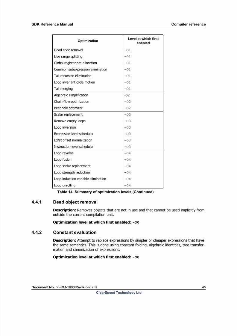
8/9/2019 SDK Reference Manual 3.1 Rev2.B
http://slidepdf.com/reader/full/sdk-reference-manual-31-rev2b 45/204
SDK Reference Manual Compiler reference
Document No. 06-RM-1600 Revision: 2.B 45
ClearSpeed Technology Ltd
4.4.1 Dead object removal
Description: Removes objects that are not in use and that cannot be used implicitly fromoutside the current compilation unit.
Optimization level at which first enabled: -O0
4.4.2 Constant evaluation
Description: Attempt to replace expressions by simpler or cheaper expressions that havethe same semantics. This is done using constant folding, algebraic identities, tree transfor-mation and canonization of expressions.
Optimization level at which first enabled: -O0
Dead code removal -O1
Live range splitting -O1
Global register pre-allocation -O1
Common subexpression elimination -O1
Tail recursion elimination -O1
Loop invariant code motion -O1
Tail merging -O1
Algebraic simplification -O2
Chain-flow optimization -O2
Peephole optimizer -O2
Scalar replacement -O3
Remove empty loops -O3
Loop inversion -O3
Expression-level scheduler -O3
Ld/st offset normalization -O3
Instruction-level scheduler -O3
Loop reversal -O4
Loop fusion -O4
Loop scalar replacement -O4
Loop strength reduction -O4
Loop induction variable elimination -O4
Loop unrolling -O4
OptimizationLevel at which first
enabled
Table 14. Summary of optimization levels (Continued)

8/9/2019 SDK Reference Manual 3.1 Rev2.B
http://slidepdf.com/reader/full/sdk-reference-manual-31-rev2b 46/204
Compiler reference SDK Reference Manual
46 Document No. 06-RM-1600 Revision: 2.B
ClearSpeed Technology Ltd
4.4.3 Switch transformation
Description: Replace switch statements by jump-tables or if-else chains
Optimization level at which first enabled: -O0
Notes: If-else chains will be produced unless a jump-table pragma is used.
User Controls: A pragma is available to produce a jump-table for any particular switchstatement. To instrument any particular switch, the following text should be added immedi-ately before the switch statement of concern:
#pragma switch jumptable
4.4.4 Global register allocation
Description: Allocate local variables and function parameters to registers where possible.
Optimization level at which first enabled: -O1
4.4.5 Basic-block ordering
Description: Try and place the basic blocks within the current procedure’s control-flowgraph into the most efficient order possible. The engine uses information concerning howoften a block is likely to be used, the probability of taking any particular edge when branchingfrom the block and the cost of taking branches from the block. The engine reorderssequences of blocks that have unconditional jumps between them to minimize the numberof unconditional jumps.
Optimization level at which first enabled: -O1
4.4.6 Share-string initializersDescription: Duplicate constant initializers that have equal size and contents are replacedby a single version.
Optimization level at which first enabled: -O1
4.4.7 Dead block removal
Description: Removal of basic blocks that are not reachable from the procedure entry point.
Optimization level at which first enabled: -O1
4.4.8 Basic-block mergingDescription: Merge basic blocks that have a one-to-one flow relation, for example basicblocks A and B when block B is the only successor of block A and block A is the only prede-cessor of block B.
Optimization level at which first enabled: -O1
8/9/2019 SDK Reference Manual 3.1 Rev2.B
http://slidepdf.com/reader/full/sdk-reference-manual-31-rev2b 47/204
SDK Reference Manual Compiler reference
Document No. 06-RM-1600 Revision: 2.B 47
ClearSpeed Technology Ltd
4.4.9 Move post-operator assignments
Description: An optimization to produce more optimal code sequences resulting from Cpost-fix operations, than are produced automatically by the compiler front-end, and to try toeliminate the unnecessary use of temporaries.
Optimization level at which first enabled: -O1
4.4.10 Copy propagation
Description: Identify statements that assign one variable to another and replace all subse-quent uses of the left-hand side by the right-hand side. The variables involved will be localvariables or parameters.
Optimization level at which first enabled: -O1
4.4.11 Strength reduction
Description: Try to replace some operations with forms that will execute more efficientlyon the target hardware, for example quite often integer multiplication can be done usingcheaper shift instructions.
Optimization level at which first enabled: -O1
4.4.12 Constant propagation
Description: Find assignments of constant expressions to variables and replace subsequentuses of the variable that are reached by the constant assignment with the constant expres-sion.
Optimization level at which first enabled: -O1
4.4.13 Dead code removal
Description: Remove assignments to objects that are not subsequently used.
Optimization level at which first enabled: -O1
4.4.14 Live range splitting
Description: The live range of an object goes from the point at which it is defined to thepoints at which it is used and ultimately ends when the object is redefined (this is termed a`killing definition’). When objects are allocated to registers, long live ranges generally corre-
spond to high register pressure, this optimization attempts to split live ranges, which in turnmay help to prevent high register pressure.
Optimization level at which first enabled: -O1
4.4.15 Global register preallocation
Description: Local or global variables that are not likely to be allocated to registers are con-sidered for caching in newly created (local) temporary variables, which are made high priorityregister candidates. Uses of the local or global variable are replaced by used of the new tem-
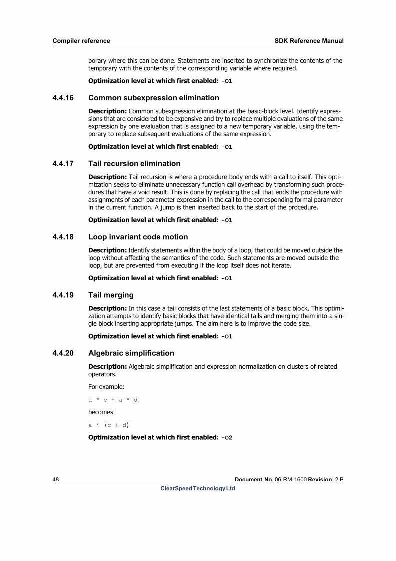
8/9/2019 SDK Reference Manual 3.1 Rev2.B
http://slidepdf.com/reader/full/sdk-reference-manual-31-rev2b 48/204
Compiler reference SDK Reference Manual
48 Document No. 06-RM-1600 Revision: 2.B
ClearSpeed Technology Ltd
porary where this can be done. Statements are inserted to synchronize the contents of thetemporary with the contents of the corresponding variable where required.
Optimization level at which first enabled: -O1
4.4.16 Common subexpression elimination
Description: Common subexpression elimination at the basic-block level. Identify expres-sions that are considered to be expensive and try to replace multiple evaluations of the sameexpression by one evaluation that is assigned to a new temporary variable, using the tem-porary to replace subsequent evaluations of the same expression.
Optimization level at which first enabled: -O1
4.4.17 Tail recursion elimination
Description: Tail recursion is where a procedure body ends with a call to itself. This opti-
mization seeks to eliminate unnecessary function call overhead by transforming such proce-dures that have a void result. This is done by replacing the call that ends the procedure withassignments of each parameter expression in the call to the corresponding formal parameterin the current function. A jump is then inserted back to the start of the procedure.
Optimization level at which first enabled: -O1
4.4.18 Loop invariant code motion
Description: Identify statements within the body of a loop, that could be moved outside theloop without affecting the semantics of the code. Such statements are moved outside theloop, but are prevented from executing if the loop itself does not iterate.
Optimization level at which first enabled:-O1
4.4.19 Tail merging
Description: In this case a tail consists of the last statements of a basic block. This optimi-zation attempts to identify basic blocks that have identical tails and merging them into a sin-gle block inserting appropriate jumps. The aim here is to improve the code size.
Optimization level at which first enabled: -O1
4.4.20 Algebraic simplification
Description: Algebraic simplification and expression normalization on clusters of related
operators.For example:
a * c + a * d
becomes
a * (c + d)
Optimization level at which first enabled: -O2

8/9/2019 SDK Reference Manual 3.1 Rev2.B
http://slidepdf.com/reader/full/sdk-reference-manual-31-rev2b 49/204
SDK Reference Manual Compiler reference
Document No. 06-RM-1600 Revision: 2.B 49
ClearSpeed Technology Ltd
4.4.21 Chain flow optimization
Description: Where possibly, eliminate unnecessary control flow.
Optimization level at which first enabled: -O2
4.4.22 Peephole optimizer
Description: Replace sequences of instructions with less-expensive versions which have thesame effect. For example, combining two adjacent load instructions which have sufficiently-aligned register and address arguments into one larger load instruction, when all appropriateconstraints are met. Several small optimizations are performed at this level as long as thesemantics of the code are not altered.
Optimization level at which first enabled: -O2
4.4.23 Scalar replacement
Description: Replace local variables that have aggregate type (for example structures,unions and arrays) where only the components of the aggregate structure are addressed(and not the whole entity), by a set of local variables that represent the fields or elements ofthe structure. The aim of doing this is to try and get the individual elements into registersand reduce unnecessary stack-address calculations.
Optimization level at which first enabled: -O3
4.4.24 Remove empty loops
Description: Remove loops that have an empty body, if necessary leave an assignment tothe loop control variable.
Optimization level at which first enabled: -O3
4.4.25 Loop inversion
Description: Where possible, change a while-do loop into a do-while loop with the goal ofreducing the number of branches required. The transformed loop is protected by a new ifcondition when it is not known at compile time whether the loop will iterate at all.
Optimization level at which first enabled: -O3
4.4.26 Expression-level scheduler
Description: Respecting dependencies, attempt to rearrange expressions into the mostoptimal order, giving the shortest runtime according to the expected latency of the sum ofinstructions used by an expression.
Optimization level at which first enabled: -O3
4.4.27 ld/st offset normalization
Description: The compiler will try to use mono registers to cache commonly used offsets toload/store instructions that are greater than 128. A load/store with an offset greater than

8/9/2019 SDK Reference Manual 3.1 Rev2.B
http://slidepdf.com/reader/full/sdk-reference-manual-31-rev2b 50/204
Compiler reference SDK Reference Manual
50 Document No. 06-RM-1600 Revision: 2.B
ClearSpeed Technology Ltd
128 is slower than a normal load/store. So the optimization will store a common offset in aregister to be reused instead of performing the more expensive operation.
Optimization level at which first enabled: -O3
4.4.28 Instruction-level scheduler
Description:Respecting dependencies, attempt to rearrage instructions into the most opti-mal order, giving the shortest runtime according to the expected latency. Often this improvesthe overlap between load/store instructions and compute instructions.
Optimization level at which first enabled: -O3
4.4.29 Loop reversal
Description: Rewrite a loop so as to execute the iterations in reverse order.
Optimization level at which first enabled: -O4
4.4.30 Loop fusion
Description: Two adjacent loops are fused into one loop when a number of constraints aremet. The loops must have the same iteration count and be data-independent from eachother. When the iteration counters for the loops are different, one of them will be eliminated.
Optimization level at which first enabled: -O4
4.4.31 Loop scalar replacement
Description: Search for address locations that are overwritten in each loop iteration, wherethe location is expected to be in memory. The location is replaced by a scalar object through-out the loop, and assigned upon loop exit.
For example:
for(i=0; i<10; i++){arr[j] = arr[j] + i;
}
can be rewritten as:
for(i=0, tmp=arr[j]; i<10; i++){tmp = tmp + i;
}arr[j] = tmp;
Optimization level at which first enabled: -O4
4.4.32 Loop strength reduction
Description: Rewrite array index expressions of loop variables into pointer operations andrewrite pointer expressions of loop variables into incremented pointers.
Optimization level at which first enabled: -O4
8/9/2019 SDK Reference Manual 3.1 Rev2.B
http://slidepdf.com/reader/full/sdk-reference-manual-31-rev2b 51/204
SDK Reference Manual Compiler reference
Document No. 06-RM-1600 Revision: 2.B 51
ClearSpeed Technology Ltd
4.4.33 Loop induction variable elimination
Description: Try to reduce the number of variables in the body of a loop by rewriting vari-ables into functions of the loop control variable where possible. This should reduce registerpressure within a loop.
Optimization level at which first enabled: -O4
4.4.34 Loop unrolling
Description: Duplicate the body of a loop multiple times in order to eliminate loop controloverhead. This may also offer more opportunity for scheduling improvements within the bodyof the unrolled loop.
Optimization level at which first enabled: -O4
Notes: Using the pragmas below will only have an effect at an optimization level at whichloop unrolling is enabled (-O4).
User controls: There are a number of pragmas available for the programmer to use to influ-ence the behavior of the loop unroller. Each of these pragmas should be placed immediatelybefore the loop to be affected.
#pragma loop no unroll
This can be used to prevent the loop from being unrolled.
#pragma loop unroll(nr )
This can be used to request a loop to be unrolled a certain number of times. The parameternr should be a positive integral value.
#pragma loop maxunroll(nr )
This pragma sets a limit on the number of times the loop will be unrolled. Set immediatelybefore the loop you want to affect.
nr should be replaced for use by a positive integral value indicating the maximum unroll fac-tor for the following loop.

8/9/2019 SDK Reference Manual 3.1 Rev2.B
http://slidepdf.com/reader/full/sdk-reference-manual-31-rev2b 52/204
Macro assembler reference SDK Reference Manual
52 Document No. 06-RM-1600 Revision: 2.B
ClearSpeed Technology Ltd
5 Macro assembler reference
mass is a generic macro assembler which produces object files for CSX processors. The same
assembler can be used for multiple targets, depending on the current configuration, see sec-tion Section 1.9: Configuration file on page 17 in Chapter 1: SDK overview .
For information on the format and syntax of the assembly language, see Chapter 14: Assem- bly language .
5.1 Invoking the assembler
The assembler takes a file containing assembler source code and generates an output objectfile. The assembler will generate the output filename from the input filename by replacingthe file suffix with .cso, unless this has been overridden by using the -o option. The assem-bler command is:
mass [option]* input-file
For example, the following command will assemble the source file foo.s and generate theoutput file foo.cso in the same directory:
mass -o foo.cso foo.s
5.2 Command-line options
As well as the standard command-line options, see the Chapter 1: SDK overview , there area set of assembler-specific command-line options. These are summarized in Table 15 .
--dwarf2 -g
--enable-stack-size
--endianness -E
--info -i
--mist-file -m
--xml -x
The command-line options may be specified in any order, and may be repeated.
Long nameShort
nameValid values Description
--chip-id -C integer
Generates debugging information
integer
big | little Endianness of the device
instructionDisplay a description of a given
instruction specified as a string constant.
Adds a file containing an instruction setdefinition. May be specified more than
once.
Generate instruction documentation in
XML format
Table 15. Summary of mass command-line options

8/9/2019 SDK Reference Manual 3.1 Rev2.B
http://slidepdf.com/reader/full/sdk-reference-manual-31-rev2b 53/204
SDK Reference Manual Macro assembler reference
Document No. 06-RM-1600 Revision: 2.B 53
ClearSpeed Technology Ltd
-g
This option causes the assembler to generate line number information for use by the debug-ger.
-o file_name
--output file_name
The output file name. If no name is specified, the assembler generates an outputfilename from the input file name with the extension .cso.
-m file_name
--mist-file file_name
This option specifies a file containing defintiions of extra instructions for use by the assem-bler. If not specified, only the standard file, iset.mst, will be used.

8/9/2019 SDK Reference Manual 3.1 Rev2.B
http://slidepdf.com/reader/full/sdk-reference-manual-31-rev2b 54/204
Macro assembler reference SDK Reference Manual
54 Document No. 06-RM-1600 Revision: 2.B
ClearSpeed Technology Ltd
-i instruction
--info instruction
Provides online help on the assembler instructions. If instruction is “index”, it will list thenames of all the instructions. An example of the output is shown in Figure 4 .
Name : add (integer)Arguments : dst, src0, src1Synopsis : dst = src0 + src1.Constraints:
All operands haveequal width to
All operands havetype integer.Side Effects : Updates the status register.Note:This can be chained together with addc to make a larger add. For example,add 0:p2, 2:p2, 4:p2 is equivalent to add 0:p1, 2:p1, 4:p1 followed by addc1:p1, 3:p1, 5:p1 (little endian).
Details:m2us m2us m2us 1hardwarem2us m2us il2us 2hardwarep1us p1us p1us 1microcodep1us p1us m2us 1microcodep1us p1us il1us 1microcodep2us p2us p2us 2microcode
p2us p2us m2us 2microcodep2us p2us il2us 2microcodep4us p4us p4us 4microcode
Name : add (floating point 32 bit)Arguments : dst, src0, src1Synopsis : dst = src0 + src1.Constraints:
All operands have type float.All operands have width of 4.
src1 has not a domain of label.Note:The mono version of this instruction will set the predicates. The negativeand zero flag will map onto the normal status flags. See the referencemanual for more information on how the other predicates are set. The polyversion will set a seperate floating point add status register. This
Figure 4.Sample --info output
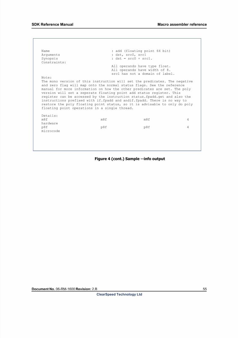
8/9/2019 SDK Reference Manual 3.1 Rev2.B
http://slidepdf.com/reader/full/sdk-reference-manual-31-rev2b 55/204
SDK Reference Manual Macro assembler reference
Document No. 06-RM-1600 Revision: 2.B 55
ClearSpeed Technology Ltd
Figure 4 (cont.) Sample --info output
Name : add (floating point 64 bit)
Arguments : dst, src0, src1Synopsis : dst = src0 + src1.Constraints:
All operands have type float.All operands have width of 8.src1 has not a domain of label.
Note:The mono version of this instruction will set the predicates. The negativeand zero flag will map onto the normal status flags. See the referencemanual for more information on how the other predicates are set. The polyversion will set a seperate floating point add status register. Thisregister can be accessed by the instruction status.fpadd.get and also theinstructions prefixed with if.fpadd and andif.fpadd. There is no way torestore the poly floating point status, so it is advisable to only do polyfloating point operations in a single thread.
Details:m8f m8f m8f 4hardwarep8f p8f p8f 4microcode

8/9/2019 SDK Reference Manual 3.1 Rev2.B
http://slidepdf.com/reader/full/sdk-reference-manual-31-rev2b 56/204
Linker reference SDK Reference Manual
56 Document No. 06-RM-1600 Revision: 2.B
ClearSpeed Technology Ltd
6 Linker reference
To get the most out of this chapter, you need to have a working knowledge of the funda-
mental concepts related to executable file organization, symbolic data representation and lowlevel programming. Some of these concepts are introduced in the Chapter 5: Macro assem- bler reference , for other sources information see the Bibliography .
The linker constructs executable files by combining a set of input object files and libraries,relocating the data and resolving the symbolic references. This is a multi pass linker. Thismeans that the order in which input files are presented for linking is not vital for the successof the process. In a situation where a file references a symbol defined in a library which pre-ceded that file, the linker will re-scan the set of input libraries until no new symbols are found.
The supported object file format is ELF [9]: Executable and Linkable Format (ELF) .
6.1 Basic terminology and conceptsThis section briefly introduces some of the key terms that will be used throughout this chap-ter.
Section: Sections provide storage for common types of information, such as data,
program code (or “text”), debugging information and so on. Sections may be loadable:
these are sections that contain data that will be loaded into the processors memory
before a program is executed.
Segment: Segments group together sections of a common type. The purpose of this is
mainly to facilitate the loader in loading the executable image onto the device.
Symbol: A named representation of a piece of data or a location in the code.
Symbolic reference: Addresses or other values defined in terms of symbols in theprogram text or a data section. Some symbols, particularly addresses, may not get
their final value until the executable object code is generated.
Relocation: The process of resolving symbolic references by calculating and inserting
the true addresses of the symbols into locations which reference them.
6.2 Invoking the linker
The linker takes a list of object files and generates an output executable file. The linker willgenerate an output file called a.out, unless this has been overridden by using the -o option.The linker command is:
cld [option]* input_files
For example, the following command will link the object file foo.cso with the librarybar.csa and generate the executable file foo.csx in the same directory:
cld -o foo.csx foo.cso bar.csa
6.3 Command-line options
As well as the standard command-line options, see the Chapter 1: SDK overview , there area set of linker-specific command-line options. These are summarized in Table 16 .

8/9/2019 SDK Reference Manual 3.1 Rev2.B
http://slidepdf.com/reader/full/sdk-reference-manual-31-rev2b 57/204
SDK Reference Manual Linker reference
Document No. 06-RM-1600 Revision: 2.B 57
ClearSpeed Technology Ltd
Long nameShort
nameValid values Description
--output -o file_name the name of the output file
--library -l lib_name the name of the input library
--library-path -L directory library search path
--nostdlibs suppress the inclusion of standard
libraries
--nostdlibpath do not search for libraries in standard
library paths
--nostdsymbols do not force resolution of standard
symbols
--entry -esymbol_name
specifies what symbol should be used as
an entry point for the executable
--Tbss address start of the mono bss section
--Tdata address start of the mono data section
--Ttext address start of the text section
--Pbss address start of the poly bss section
--Pdata address start of the poly data section
--restrict
chip-index
restrict memory resources visible to the
linker to a selected chip. The chip index is
zero based.
--print-map -M create a map of the object file
--Map file_name create a map and write it to a file
--creff create a cross reference table
--endianness -E big | little link for big or little-endian target.
--relocatable -r include relocation info in the output file
--dynamic build this executable to be dynamically
loaded
--trace-symbol -y symbol_name print references to the given symbol
--defsym symbol_name= expr
Where symbol_name is
an identifier and expr a
numeric value
define the symbol and set its value to
expr
--strip-all -s do not include the symbol table in the
output file
--strip-debug -S do not include the debug info in the
output file
--discard-all -x discard all local symbols
--warn-layout allow the linker to warn and continue
even when segment layout errors have
been detected
Table 16. Summary of cld command-line options

8/9/2019 SDK Reference Manual 3.1 Rev2.B
http://slidepdf.com/reader/full/sdk-reference-manual-31-rev2b 58/204
Linker reference SDK Reference Manual
58 Document No. 06-RM-1600 Revision: 2.B
ClearSpeed Technology Ltd
The command-line options to cld may be specified in any order, and may be repeated. Thearguments which are not options are assumed to be input object files or libraries. Command-line options which are unrecognized, are ignored and a suitable warning is printed.
6.3.1 Category: files and paths
-o file_name
--output file_name
Specifies the output file name (the default is a.out).
-l library --library library
Defines an input library file name. By convention, the linker converts the library name spec-ified into a file name by pre-pending lib to the name and appending the file extension .csa.This file name is then looked for in the search path.
Note that it is also possible to specify the full library name as an argument as if it were aregular object file. In this case the library search is limited to the current directory.
Some libraries are included automatically (see the description of the--nostdlibs
optionbelow for details).
-L dir --library-path dir
Specifies another directory library search path. Libraries specified with the -l option will besearched for in the paths specified with the -L option. The search will commence, by default,with the current directory and continue in the order in which the directories appear on thecommand line.
To support differing conventions on different operating systems, both forward and backslashes are supported as directory separators in the path. The path can finish with a trailingslash; if this is omitted, one is appended to the path.
--nostdlibs
Suppresses the inclusion of standard libraries. The libraries to be automatically scanned forsymbols by the linker can be specified in the SDK configuration file.
--nostdlibpath
Forces the linker to ignore the default library search paths specified in the configuration file.
-v verbose mode
--version -V print the versioning and emulationinformation
--help -h print this message and exit
Long nameShort
nameValid values Description
Table 16. Summary of cld command-line options (Continued)
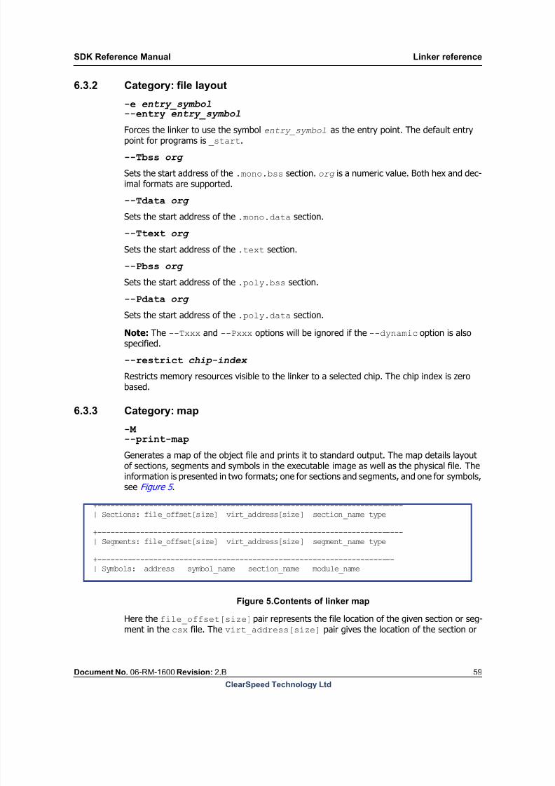
8/9/2019 SDK Reference Manual 3.1 Rev2.B
http://slidepdf.com/reader/full/sdk-reference-manual-31-rev2b 59/204
SDK Reference Manual Linker reference
Document No. 06-RM-1600 Revision: 2.B 59
ClearSpeed Technology Ltd
6.3.2 Category: file layout
-e entry_symbol
--entry entry_symbol
Forces the linker to use the symbol entry_symbol as the entry point. The default entrypoint for programs is _start.
--Tbss org
Sets the start address of the .mono.bss section. org is a numeric value. Both hex and dec-imal formats are supported.
--Tdata org
Sets the start address of the .mono.data section.
--Ttext org
Sets the start address of the .text section.
--Pbss org
Sets the start address of the .poly.bss section.
--Pdata org
Sets the start address of the .poly.data section.
Note: The --Txxx and --Pxxx options will be ignored if the --dynamic option is alsospecified.
--restrict chip-index
Restricts memory resources visible to the linker to a selected chip. The chip index is zerobased.
6.3.3 Category: map
-M --print-map
Generates a map of the object file and prints it to standard output. The map details layoutof sections, segments and symbols in the executable image as well as the physical file. Theinformation is presented in two formats; one for sections and segments, and one for symbols,see Figure 5 .
+-----------------------------------------------------------------------| Sections: file_offset[size] virt_address[size] section_name type
+-----------------------------------------------------------------------| Segments: file_offset[size] virt_address[size] segment_name type
+---------------------------------------------------------------------| Symbols: address symbol_name section_name module_name
Figure 5.Contents of linker map
Here the file_offset[size] pair represents the file location of the given section or seg-ment in the csx file. The virt_address[size] pair gives the location of the section or

8/9/2019 SDK Reference Manual 3.1 Rev2.B
http://slidepdf.com/reader/full/sdk-reference-manual-31-rev2b 60/204
Linker reference SDK Reference Manual
60 Document No. 06-RM-1600 Revision: 2.B
ClearSpeed Technology Ltd
segment as it will be loaded in the device memory. The type field says whether the sectionor segment is loadable into mono or poly memory space of the device or whether it is purelydata that is stored in the object file. The valid values are: MONO_LOAD, POLY_LOAD andUNDEF.
The symbol information consists of a relocated address, symbol name, section name in whichthe symbol has been defined and the module name which supplied the definition. If the sym-bol was defined in the user file, the name with extension will be given. If the symbol comesfrom the library, the library name without the prefix or a suffix will be printed. For instance,if the full library name were libdbg.a, the module_name shown will be dbg.
Examples of how the map information can be used are presented in Section 6.7 .
--Map filename
Generates a map and writes it to a file.
--creff
Generates a cross-reference table. The cross-reference table lists symbols, the definitions ofwhich have been found, and details all locations where the symbols have been referenced.By default, the cross-reference table is printed to standard output. If the --Map option isalso specified, the table is appended to the map file.
The format of the cross-reference table is shown in Figure 6
+-----------------------------------------------------------------------| X reference: sym_name in module_name:section_name @ addr_org [reloced ]| ref_in_module @ addr_org [reloced ]
.
Figure 6.Format of cross-reference table
The first line displays the symbol name, module (file) name, and the section name in whichthe symbol was defined. Also, the address pair is given that specifies this location. Theaddr_org field is an address relative to the start of the section before relocation (always 0).The reloced field reflects the actual placement of the sections in the executable image andis the true address where the symbol can be found in the relevant domain (mono or poly) ofthe address space of the device.
This line is followed by zero or more lines, which contain the module name and the addresspair describing the location where the symbol has been referenced.
6.3.4 Category: symbols
--defsym name=value
Sets the value of a symbol. name is a string, value an integer given in decimal or hex format.If the symbol was external, it is redefined to be global. This option can be used multipletimes.
This defines an absolute symbol; that is, the value parameter is the final value of the symbol(see section Section 14.3.2: Symbols on page 182 for more information about symbol types).
8/9/2019 SDK Reference Manual 3.1 Rev2.B
http://slidepdf.com/reader/full/sdk-reference-manual-31-rev2b 61/204
SDK Reference Manual Linker reference
Document No. 06-RM-1600 Revision: 2.B 61
ClearSpeed Technology Ltd
--dynamic
Builds this executable to be dynamically loaded. If this option is used then any options whichspecify absolute addresses, such as --Ttext, will be ignored.
--nostdsymbolsIt is possible to specify symbols in the configuration file that the linker will treat as externalsymbols to be resolved, even if they were never explicitly referenced in the code. This is use-ful for forcing special libraries, such as the bootstrap or prologue/epilogue code, to beincluded with the executable.
This option switches off this default linker behavior.
-r
--relocatable
Makes the output file relocatable. All relocation information will be included in the output file.
-s
--strip-all
Omits all symbol information from the output file.
-S
--strip-debug
Omits all debug information from the output file.
--warn-layout
Warns when detecting that segments overlap in memory. This may occur when the --Txxx or --Pxxx family of options are used incorrectly. The default linker behavior is to report anerror and exit should a conflict be detected. This option disables the default behavior. SeeSection 6.4: File layout on page 62 for details of file layout.
-x
--discard-all
Omits all local symbol information from the output file. Similar to -s but global symbols areleft in the output file.
-y symbol_name
--trace-symbol symbol_name
Causes the specified symbol to be traced . Each reference to the chosen symbol will bereported (together with a module name and local address). This option can be specified mul-tiple times to trace multiple symbols. If the --Map option was specified as well then the sym-bol trace information is appended to the map file.
The format in which the information is presented is analogous to the --creff option.
6.3.5 Category: other
-E big | little --endianness big | little
Link for big or little-endian target.
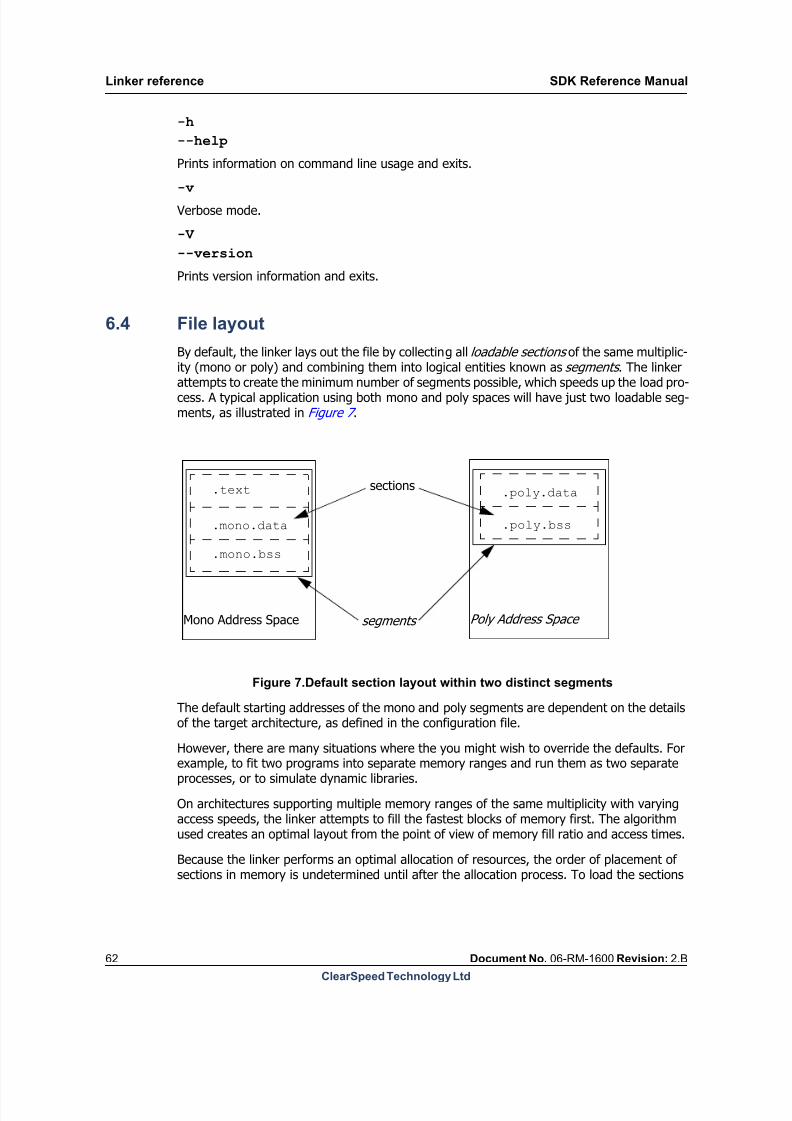
8/9/2019 SDK Reference Manual 3.1 Rev2.B
http://slidepdf.com/reader/full/sdk-reference-manual-31-rev2b 62/204
Linker reference SDK Reference Manual
62 Document No. 06-RM-1600 Revision: 2.B
ClearSpeed Technology Ltd
-h
--help
Prints information on command line usage and exits.
-v
Verbose mode.
-V
--version
Prints version information and exits.
6.4 File layout
By default, the linker lays out the file by collecting all loadable sections of the same multiplic-ity (mono or poly) and combining them into logical entities known as segments . The linkerattempts to create the minimum number of segments possible, which speeds up the load pro-cess. A typical application using both mono and poly spaces will have just two loadable seg-ments, as illustrated in Figure 7 .
Mono Address Space Poly Address Space
.text
.mono.data
.mono.bss
.poly.data
.poly.bss
sections
segments
Figure 7.Default section layout within two distinct segments
The default starting addresses of the mono and poly segments are dependent on the detailsof the target architecture, as defined in the configuration file.
However, there are many situations where the you might wish to override the defaults. Forexample, to fit two programs into separate memory ranges and run them as two separateprocesses, or to simulate dynamic libraries.
On architectures supporting multiple memory ranges of the same multiplicity with varyingaccess speeds, the linker attempts to fill the fastest blocks of memory first. The algorithmused creates an optimal layout from the point of view of memory fill ratio and access times.
Because the linker performs an optimal allocation of resources, the order of placement ofsections in memory is undetermined until after the allocation process. To load the sections
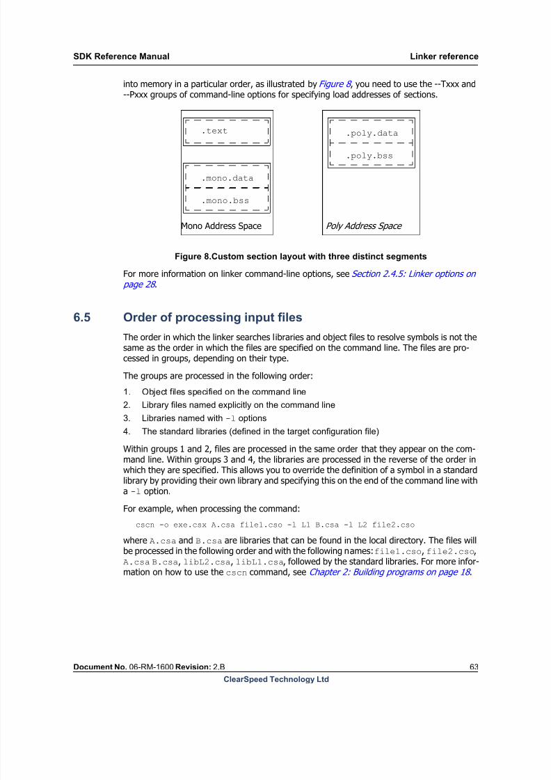
8/9/2019 SDK Reference Manual 3.1 Rev2.B
http://slidepdf.com/reader/full/sdk-reference-manual-31-rev2b 63/204
SDK Reference Manual Linker reference
Document No. 06-RM-1600 Revision: 2.B 63
ClearSpeed Technology Ltd
into memory in a particular order, as illustrated by Figure 8 , you need to use the --Txxx and--Pxxx groups of command-line options for specifying load addresses of sections.
Mono Address Space Poly Address Space
.text .poly.data
.poly.bss
.mono.bss
.mono.data
Figure 8.Custom section layout with three distinct segments
For more information on linker command-line options, see Section 2.4.5: Linker options on page 28 .
6.5 Order of processing input files
The order in which the linker searches libraries and object files to resolve symbols is not thesame as the order in which the files are specified on the command line. The files are pro-cessed in groups, depending on their type.
The groups are processed in the following order:
1. Object files specified on the command line2. Library files named explicitly on the command line
3. Libraries named with -l options
4. The standard libraries (defined in the target configuration file)
Within groups 1 and 2, files are processed in the same order that they appear on the com-mand line. Within groups 3 and 4, the libraries are processed in the reverse of the order inwhich they are specified. This allows you to override the definition of a symbol in a standardlibrary by providing their own library and specifying this on the end of the command line witha -l option.
For example, when processing the command:
cscn -o exe.csx A.csa file1.cso -l L1 B.csa -l L2 file2.cso
where A.csa and B.csa are libraries that can be found in the local directory. The files willbe processed in the following order and with the following names: file1.cso, file2.cso,A.csa B.csa, libL2.csa, libL1.csa, followed by the standard libraries. For more infor-mation on how to use the cscn command, see Chapter 2: Building programs on page 18 .
8/9/2019 SDK Reference Manual 3.1 Rev2.B
http://slidepdf.com/reader/full/sdk-reference-manual-31-rev2b 64/204
Linker reference SDK Reference Manual
64 Document No. 06-RM-1600 Revision: 2.B
ClearSpeed Technology Ltd
6.6 Search paths
The linker expects any object files or libraries specified as command line arguments to be inthe current directory. These files can also be specified with absolute or relative paths (relative
to the current directory).The linker searches for standard libraries and libraries specified with the -l option in thelinker’s search path. This is made up of three parts, searched in the following order: the cur-rent directory, the standard search path, and any extra paths specified with -L options. Thestandard search path is specified in the environment variable CSLIB.
6.7 Example
In most cases, the linker will be invoked with only the basic options: those setting the inputfiles, libraries, and output file name.
cscn -L ../lib_search_path -l a -l b my_lib.csa obj1.cso -o appl.csx
Executing the above command will result in appl.csx being built. The liba.csa and libb.csa libraries will be searched for in ../lib_search_path and the default paths.The library my_lib.csa will be looked for in the current directory only. The default librarieswill be linked automatically and will be searched for symbols only after the ones given explic-itly on the command line.
6.8 Related tools
The ClearSpeed archiver, arcs, is used to create libraries of object files. For more informa-tion, see Chapter 9: Archiver .
Since the object files conform to the ELF specification, the standard ‘binutils’ tools (for exam-ple, nm, objdump) can be used to inspect their contents.
Finally, the csdump tool can be used to display an object file’s sections together with disas-sembly and relocation information. For more information, see Chapter 10: Object file dump .
8/9/2019 SDK Reference Manual 3.1 Rev2.B
http://slidepdf.com/reader/full/sdk-reference-manual-31-rev2b 65/204
SDK Reference Manual Debugger reference
Document No. 06-RM-1600 Revision: 2.B 65
ClearSpeed Technology Ltd
7 Debugger reference
This chapter describes the changes made to the standard GDB command set to allow debug-
ging of the CSX architecture.
csgdb is a port of the GNU open source debugger GDB to support the CSX family of micro-processors. It has been extended to provide support for the Cn language and the data-par-allel architecture of the CSX processors.
The aim in porting GNU GDB to support the CSX architecture is to utilize as much of the stan-dard functionality provided and change only what is required to allow access to novel fea-tures of CSX processors. The standard GDB reference manual [12]: Debugging with GDB isprovided with the SDK. This is a comprehensive document that explains how to use all of thestandard features of the debugger.
7.1 New commands and featuresThe following new features have been added to the debugger:
connect command (see Connect command and options on page 67 ).
support for linked instructions (see Disassemble command on page 71).
peregs command (see Reading poly registers – peregs command on page 73).
pex command (see Reading poly memory – pex command on page 74).
whatis command displays information about poly values (see Symbolic debug on
page 76 ).
sysreg command (see System register viewer on page 79).
semaphores command (see TSC semaphore viewer on page 83).
In addition to these new commands, it is now also possible to display the enable state (seeViewing the enable state on page 74 ).
7.2 Invoking the debugger
When debugging a “stand-alone” application that runs entirely on the CSX processor, use thefollowing command to start the debugger from the command line:
csgdb [executable-file]
The name of the executable file to be debugged can be passed on the command line.
The debugger initializes, prints a copyright notice and then displays a command prompt:(gdb).
7.3 Using the debugger with a host application
When the code running on the CSX processor is loaded by an application running on the host,use the following method to allow both the host application and the debugger to connect tothe CSX code:
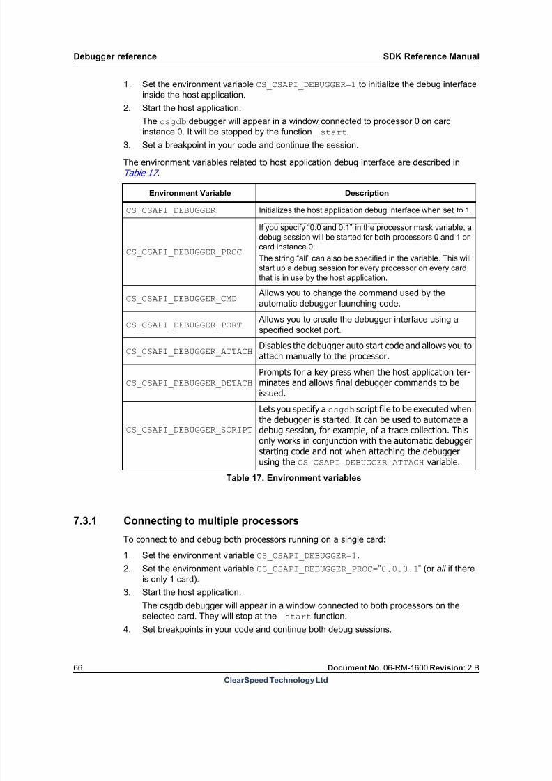
8/9/2019 SDK Reference Manual 3.1 Rev2.B
http://slidepdf.com/reader/full/sdk-reference-manual-31-rev2b 66/204
Debugger reference SDK Reference Manual
66 Document No. 06-RM-1600 Revision: 2.B
ClearSpeed Technology Ltd
1. Set the environment variable CS_CSAPI_DEBUGGER=1 to initialize the debug interface
inside the host application.
2. Start the host application.
The csgdb debugger will appear in a window connected to processor 0 on card
instance 0. It will be stopped by the function _start.
3. Set a breakpoint in your code and continue the session.
The environment variables related to host application debug interface are described inTable 17 .
Allows you to specify theprocessor connectionmask for the debugger auto-startcode. Itdefaultsto 0.0,which referencesprocessor 0 on card instance0.
Disables the debugger auto start code and allows you toattach manually to the processor.
Prompts for a key press when the host application ter-minates and allows final debugger commands to be
issued.
Lets you specify a csgdb script file to be executed whenthe debugger is started. It can be used to automate adebug session, for example, of a trace collection. Thisonly works in conjunction with the automatic debuggerstarting code and not when attaching the debuggerusing the CS_CSAPI_DEBUGGER_ATTACH variable.
7.3.1 Connecting to multiple processorsTo connect to and debug both processors running on a single card:
1. Set the environment variable CS_CSAPI_DEBUGGER=1 .
2. Set the environment variable CS_CSAPI_DEBUGGER_PROC= ”0.0.0.1” (or all if there
is only 1 card).
3. Start the host application.
The csgdb debugger will appear in a window connected to both processors on the
selected card. They will stop at the _start function.
4. Set breakpoints in your code and continue both debug sessions.
Environment Variable Description
CS_CSAPI_DEBUGGER Initializes the host application debug interface when set to 1.
CS_CSAPI_DEBUGGER_PROC
If you specify “0.0 and 0.1” in the processor mask variable, a
debug session will be started for both processors 0 and 1 on
card instance 0.
The string “all” can also be specified in the variable. This willstart up a debug session for every processor on every card
that is in use by the host application.
CS_CSAPI_DEBUGGER_CMD Allows you to change the command used by the
automatic debugger launching code.
CS_CSAPI_DEBUGGER_PORT Allows you to create the debugger interface using a
specified socket port.
CS_CSAPI_DEBUGGER_ATTACH
CS_CSAPI_DEBUGGER_DETACH
CS_CSAPI_DEBUGGER_SCRIPT
Table 17. Environment variables

8/9/2019 SDK Reference Manual 3.1 Rev2.B
http://slidepdf.com/reader/full/sdk-reference-manual-31-rev2b 67/204
SDK Reference Manual Debugger reference
Document No. 06-RM-1600 Revision: 2.B 67
ClearSpeed Technology Ltd
7.3.2 Connecting to the processor manually
To connect to the processor manually:
1. Set the environment variables CS_CSAPI_DEBUGGER=1 ,
CS_CSAPI_DEBUGGER_ATTACH=1 and CS_CSAPI_DEBUGGER_DETACH=1 .Setting CS_CSAPI_DEBUGGER initializes the debug interface inside the host
application.
Setting CS_CSAPI_DEBUGGER_ATTACH allows you to attach to the device before the
host application executes any code, and set a breakpoint.
Setting CS_CSAPI_DEBUGGER_DETACH allows you to execute debugger commands
prior to the host application terminating.
The ATTACH and DETACH environment variables do not need to be set if you want to
attach to the processor once the device has started running.
2. Start the host application and note the port, instance and chip numbers displayed by
the host application. The full path of the file loaded is also displayed by the host
application.3. In another window, start the debugger with a command line of the form:
csgdb csx_file_name port_number.instance.chip
or:ddd --debugger csgdb csx_file_name port_number.instance.chip
where port_number , instance and chip are the values that are displayed by the
host application.
For each chip that is in use by the host application, you will get a prompt to attach if the
CS_CSAPI_DEBUGGER_ATTACH environment variable is set. If you do not wish to
attach to that particular processor, press [Enter] to continue. To connect to the second
chip in a single board system, start the host application, press [Enter] to skip attaching
to the first chip and then connect the debugger to the second chip with the command
supplied in the output. It is important that you only connect the debugger when it hasstopped waiting for you to press [Enter] as this synchronizes the host application and
the debugger.
4. Set a breakpoint in the CSX code where you want to stop.
5. Press [Run] in ddd, or use the r command in csgdb.
6. Press a key in the host application window to allow it to continue.
7.4 Commands
The following sections provide an overview of the debugger commands with a detaileddescription of the new features for the CSX architecture. For clarity, irrelevant output fromcsgdb has been omitted from the following examples. Where necessary, these omissions aremarked with ellipses (...).
7.4.1 Connect command and options
csgdb is a cross-debugger, that is, it runs on a host machine and debugs a program runningon another system (the CSX processor). The connect command has been added to allowyou to specify and initialize the connection between csgdb and the remote device. Thisconnection must be made before any code can be executed within the debuggerenvironment.

8/9/2019 SDK Reference Manual 3.1 Rev2.B
http://slidepdf.com/reader/full/sdk-reference-manual-31-rev2b 68/204
Debugger reference SDK Reference Manual
68 Document No. 06-RM-1600 Revision: 2.B
ClearSpeed Technology Ltd
The connect command is executed from the csgdb prompt:
(gdb) connect0x80000000 in ?? ()(gdb)
When connected, csgdb shows the current program counter (PC) value and the symbolicinformation associated with that location.
There are a number of options to the connect command, shown inTable 18 . These are thesame as those used with csrun. See the CSX600 Runtime Software User Guide for detailsof the csrun command.
-c chip-id --chip chip-id
Selects the chip to connect to. Note that chip numbering starts with 1, as opposed to instanc-ing, which is zero based. The default is 1.
--host name | address
If the simulator is running on a different host (that is, not the same computer as the debug-ger, use this option to inform csgdb where the connection should be made.
-i number --instance number
Specifies which instance of the board or the simulator to connect to. Instancing is 0 based.The default is 0.
-m direct | attach --mode attach | attach
Specifies which mode csgdb should use to access the device. The default mode is direct.
By specifying attach the device can be accessed via the debug interface built into CSAPIhost applications.
-s
--sim
Specifies that csgdb should connect to a simulator rather than search for hardware.
Long nameShort
nameValid values Description
--chip -c integer Select a given chip.
--host name or address Connect to a specified host.
--instance -i integer Select a board or a simulator instance.
--mode -m direct | attach Select the mode of operation.
--sim -sConnect to a simulator rather than
hardware.
Table 18. Connect options summary

8/9/2019 SDK Reference Manual 3.1 Rev2.B
http://slidepdf.com/reader/full/sdk-reference-manual-31-rev2b 69/204
SDK Reference Manual Debugger reference
Document No. 06-RM-1600 Revision: 2.B 69
ClearSpeed Technology Ltd
7.4.2 Loading code
The executable code to be debugged needs to be loaded into the target device. This can bedone in two ways:
If the executable file name has been passed to the debugger on the command line, itcan be loaded by using the load command with no arguments:
csgdb cfitest.csx
...
(gdb) connect
0x80000000 in __FRAME_BEGIN_MONO__ ()
(gdb) load
(gdb)
The executable file name can also be provided as an argument to the load command:
csgdb
...
(gdb) connect
0x80000000 in ?? ()
(gdb) load /csxtests/cfitest.csx
(gdb)
7.4.3 Executing code
Once code is loaded you can start the code executing. The continue command, c, starts the
code from the entry point and runs until the program terminates:csgdb...(gdb) connect0x80000000 in ?? ()(gdb) load /csxtests/cfitest.csx(gdb) cContinuing.
Mtap 0 has terminated.Program exited normally.(gdb)
The code can also be single stepped at the instruction or source code statement level by
using the stepi or step commands. Subroutine branches can be stepped over at theinstruction or source code level by using the nexti or next command.
The command run performs the equivalent of a load followed by continue and is veryuseful for starting or restarting program execution.
7.4.4 Mono debugging
csgdb supports debugging mono code at both the instruction and source code level. Thestandard GDB commands documented in [12]: Debugging with GDB are all available for usewhen debugging mono code.
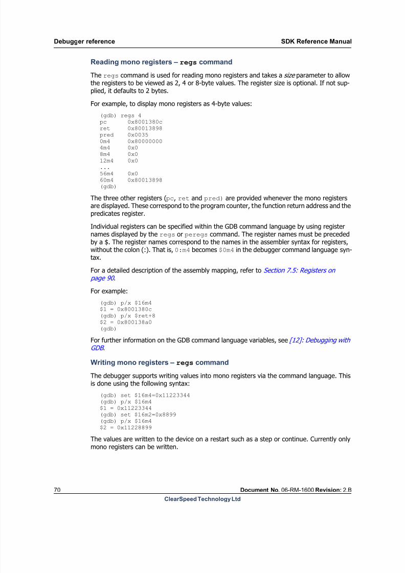
8/9/2019 SDK Reference Manual 3.1 Rev2.B
http://slidepdf.com/reader/full/sdk-reference-manual-31-rev2b 70/204
Debugger reference SDK Reference Manual
70 Document No. 06-RM-1600 Revision: 2.B
ClearSpeed Technology Ltd
Reading mono registers – regs command
The regs command is used for reading mono registers and takes a size parameter to allowthe registers to be viewed as 2, 4 or 8-byte values. The register size is optional. If not sup-plied, it defaults to 2 bytes.
For example, to display mono registers as 4-byte values:
(gdb) regs 4pc 0x8001380cret 0x80013898pred 0x00350m4 0x800000004m4 0x08m4 0x012m4 0x0...56m4 0x060m4 0x80013898(gdb)
The three other registers (pc, ret and pred) are provided whenever the mono registersare displayed. These correspond to the program counter, the function return address and thepredicates register.
Individual registers can be specified within the GDB command language by using registernames displayed by the regs or peregs command. The register names must be precededby a $. The register names correspond to the names in the assembler syntax for registers,without the colon (:). That is, 0:m4 becomes $0m4 in the debugger command language syn-tax.
For a detailed description of the assembly mapping, refer to Section 7.5: Registers on page 90 .
For example:
(gdb) p/x $16m4$1 = 0x8001380c(gdb) p/x $ret+8$2 = 0x800138a0(gdb)
For further information on the GDB command language variables, see [12]: Debugging withGDB .
Writing mono registers – regs command
The debugger supports writing values into mono registers via the command language. This
is done using the following syntax:(gdb) set $16m4=0x11223344(gdb) p/x $16m4$1 = 0x11223344(gdb) set $16m2=0x8899(gdb) p/x $16m4$2 = 0x11228899
The values are written to the device on a restart such as a step or continue. Currently onlymono registers can be written.

8/9/2019 SDK Reference Manual 3.1 Rev2.B
http://slidepdf.com/reader/full/sdk-reference-manual-31-rev2b 71/204
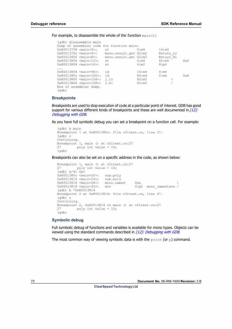
8/9/2019 SDK Reference Manual 3.1 Rev2.B
http://slidepdf.com/reader/full/sdk-reference-manual-31-rev2b 72/204
Debugger reference SDK Reference Manual
72 Document No. 06-RM-1600 Revision: 2.B
ClearSpeed Technology Ltd
For example, to disassemble the whole of the function main():
(gdb) disassemble mainDump of assembler code for function main:0x800137f8 <main+0>: st 0:m4 16:m4
0x800137fc <main+4>: mono.result.get 60:m2 Return_Lo0x80013800 <main+8>: mono.result.get 62:m2 Return_Hi0x80013804 <main+12>: st 0:m4 60:m4 0x40x80013808 <main+16>: st 4:m2 8:p4...0x80013858 <main+96>: ld 16:m4 0:m40x8001385c <main+100>: ld 60:m4 0:m4 0x40x80013860 <main+104>: j.lo 60:m2 \0x80013864 <main+108>: j.hi 62:m2 /End of assembler dump.(gdb)
Breakpoints
Breakpoints are used to stop execution of code at a particular point of interest. GDB has good
support for various different kinds of breakpoints and these are well documented in [12]:Debugging with GDB .
As you have full symbolic debug you can set a breakpoint on a function call. For example:
(gdb) b mainBreakpoint 1 at 0x8001380c: file cfitest.cn, line 27.(gdb) cContinuing.Breakpoint 1, main () at cfitest.cn:2727 poly int value = 10;(gdb)
Breakpoints can also be set on a specific address in the code, as shown below:
Breakpoint 1, main () at cfitest.cn:2727 poly int value = 10;(gdb) x/4i $pc0x8001380c <main+20>: nop.poly0x80013810 <main+24>: nop.poly0x80013814 <main+28>: mono.immed 0xa \0x80013818 <main+32>: mov 0:p2 mono_immediate /(gdb) b *0x80013814Breakpoint 2 at 0x80013814: file cfitest.cn, line 27.(gdb) cContinuing.Breakpoint 2, 0x80013814 in main () at cfitest.cn:2727 poly int value = 10;(gdb)
Symbolic debug
Full symbolic debug of functions and variables is available for mono types. Objects can beviewed using the standard commands described in [12]: Debugging with GDB .
The most common way of viewing symbolic data is with the print (or p) command.
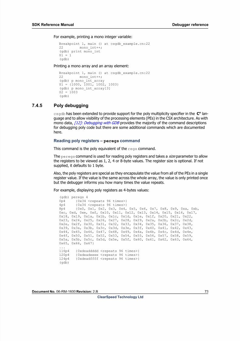
8/9/2019 SDK Reference Manual 3.1 Rev2.B
http://slidepdf.com/reader/full/sdk-reference-manual-31-rev2b 73/204
SDK Reference Manual Debugger reference
Document No. 06-RM-1600 Revision: 2.B 73
ClearSpeed Technology Ltd
For example, printing a mono integer variable:
Breakpoint 1, main () at csgdb_example.cn:2222 mono_int++;(gdb) print mono_int
$1 = 1(gdb)
Printing a mono array and an array element:
Breakpoint 1, main () at csgdb_example.cn:2222 mono_int++;(gdb) p mono_int_array$1 = {1000, 1001, 1002, 1003}(gdb) p mono_int_array[3]$2 = 1003(gdb)
7.4.5 Poly debugging
csgdb has been extended to provide support for the poly multiplicity specifier in the Cn
lan-guage and to allow visibility of the processing elements (PEs) in the CSX architecture. As withmono data, [12]: Debugging with GDB provides the majority of the command descriptionsfor debugging poly code but there are some additional commands which are documentedhere.
Reading poly registers – peregs command
This command is the poly equivalent of the regs command.
The peregs command is used for reading poly registers and takes a size parameter to allowthe registers to be viewed as 1, 2, 4 or 8-byte values. The register size is optional. If notsupplied, it defaults to 1 byte.
Also, the poly registers are special as they encapsulate the value from all of the PEs in a singleregister value. If the value is the same across the whole array, the value is only printed oncebut the debugger informs you how many times the value repeats.
For example, displaying poly registers as 4-bytes values:
(gdb) peregs 40p4 {0x34 <repeats 96 times>}4p4 {0x34 <repeats 96 times>}8p4 {0x0, 0x1, 0x2, 0x3, 0x4, 0x5, 0x6, 0x7, 0x8, 0x9, 0xa, 0xb,0xc, 0xd, 0xe, 0xf, 0x10, 0x11, 0x12, 0x13, 0x14, 0x15, 0x16, 0x17,0x18, 0x19, 0x1a, 0x1b, 0x1c, 0x1d, 0x1e, 0x1f, 0x20, 0x21, 0x22,0x23, 0x24, 0x25, 0x26, 0x27, 0x28, 0x29, 0x2a, 0x2b, 0x2c, 0x2d,0x2e, 0x2f, 0x30, 0x31, 0x32, 0x33, 0x34, 0x35, 0x36, 0x37, 0x38,
0x39, 0x3a, 0x3b, 0x3c, 0x3d, 0x3e, 0x3f, 0x40, 0x41, 0x42, 0x43,0x44, 0x45, 0x46, 0x47, 0x48, 0x49, 0x4a, 0x4b, 0x4c, 0x4d, 0x4e,0x4f, 0x50, 0x51, 0x52, 0x53, 0x54, 0x55, 0x56, 0x57, 0x58, 0x59,0x5a, 0x5b, 0x5c, 0x5d, 0x5e, 0x5f, 0x60, 0x61, 0x62, 0x63, 0x64,0x65, 0x66, 0x67}...116p4 {0xdeaddddd <repeats 96 times>}120p4 {0xdeadeeee <repeats 96 times>}124p4 {0xdeadffff <repeats 96 times>}(gdb)

8/9/2019 SDK Reference Manual 3.1 Rev2.B
http://slidepdf.com/reader/full/sdk-reference-manual-31-rev2b 74/204
Debugger reference SDK Reference Manual
74 Document No. 06-RM-1600 Revision: 2.B
ClearSpeed Technology Ltd
As with the regs command the register names are available in the command language. Thepoly registers are accessed from the command line with the name preceded by a $, as shownbelow:
(gdb) print/d $8p4
$3 = {0, 1, 2, 3, 4, 5, 6, 7, 8, 9, 10, 11, 12, 13, 14, 15, 16, 17,18, 19, 20, 21, 22, 23, 24, 25, 26, 27, 28, 29, 30, 31, 32, 33, 34,35, 36, 37, 38, 39, 40, 41, 42, 43, 44, 45, 46, 47, 48, 49, 50, 51,52, 53, 54, 55, 56, 57, 58, 59, 60, 61, 62, 63, 64, 65, 66, 67, 68,69, 70, 71, 72, 73, 74, 75, 76, 77, 78, 79, 80, 81, 82, 83, 84, 85,86, 87, 88, 89, 90, 91, 92, 93, 94, 95}(gdb)
The poly registers can also be indexed to view the value on an individual PE. In this example,the values of register 8 on PEs 10 and 84 are displayed:
(gdb) print/d $8p4[10]$4 = 10(gdb) print/d $8p4[84]$5 = 84
(gdb)
Reading poly memory – pex command
This command is the poly equivalent of the standard x command.
The pex command is used to display memory across a range of PEs using the same formatsavailable with the x command. Symbolic names can also be passed to the pex command.
Example 1: printing a word in decimal from the address 0x28 on PEs 0 to 20:
(gdb) pex/dw 0x28 0..20(PE 0) 0x28 <__FRAME_BEGIN_POLY__+40>: 1000(PE 1) 0x28 <__FRAME_BEGIN_POLY__+40>: 1001(PE 2) 0x28 <__FRAME_BEGIN_POLY__+40>: 1002
...(PE 18) 0x28 <__FRAME_BEGIN_POLY__+40>: 1018(PE 19) 0x28 <__FRAME_BEGIN_POLY__+40>: 1019(PE 20) 0x28 <__FRAME_BEGIN_POLY__+40>: 1020(gdb)
Example 2: printing 4 bytes from address &poly_int_array on PEs 50 to 75:
(gdb) pex/4b &poly_int_array 50..75(PE 50) 0x28 <__FRAME_BEGIN_POLY__+40>: 0x1a 0x04 0x00 0x00(PE 51) 0x28 <__FRAME_BEGIN_POLY__+40>: 0x1b 0x04 0x00 0x00(PE 52) 0x28 <__FRAME_BEGIN_POLY__+40>: 0x1c 0x04 0x00 0x00...(PE 73) 0x28 <__FRAME_BEGIN_POLY__+40>: 0x31 0x04 0x00 0x00(PE 74) 0x28 <__FRAME_BEGIN_POLY__+40>: 0x32 0x04 0x00 0x00
(PE 75) 0x28 <__FRAME_BEGIN_POLY__+40>: 0x33 0x04 0x00 0x00(gdb)
Viewing the enable state
When debugging applications that use poly conditional code, it is useful to see the enablestate of the PEs. In csgdb, the enable state is mapped into a register name $enable. Thisregister can be viewed using the standard print command.
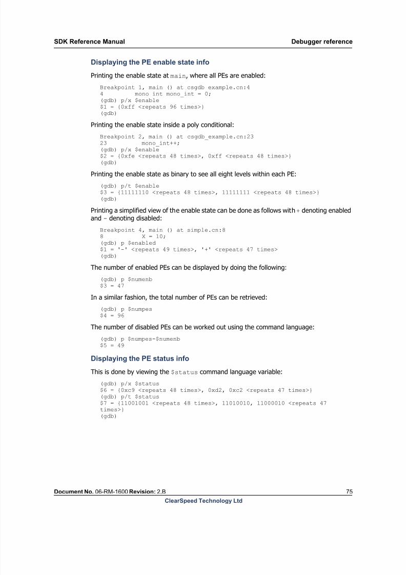
8/9/2019 SDK Reference Manual 3.1 Rev2.B
http://slidepdf.com/reader/full/sdk-reference-manual-31-rev2b 75/204
SDK Reference Manual Debugger reference
Document No. 06-RM-1600 Revision: 2.B 75
ClearSpeed Technology Ltd
Displaying the PE enable state info
Printing the enable state at main, where all PEs are enabled:
Breakpoint 1, main () at csgdb_example.cn:4
4 mono int mono_int = 0;(gdb) p/x $enable$1 = {0xff <repeats 96 times>}(gdb)
Printing the enable state inside a poly conditional:
Breakpoint 2, main () at csgdb_example.cn:2323 mono_int++;(gdb) p/x $enable$2 = {0xfe <repeats 48 times>, 0xff <repeats 48 times>}(gdb)
Printing the enable state as binary to see all eight levels within each PE:
(gdb) p/t $enable
$3 = {11111110 <repeats 48 times>, 11111111 <repeats 48 times>}(gdb)
Printing a simplified view of the enable state can be done as follows with + denoting enabledand - denoting disabled:
Breakpoint 4, main () at simple.cn:88 X = 10;(gdb) p $enabled$1 = '-' <repeats 49 times>, '+' <repeats 47 times>(gdb)
The number of enabled PEs can be displayed by doing the following:
(gdb) p $numenb
$3 = 47In a similar fashion, the total number of PEs can be retrieved:
(gdb) p $numpes$4 = 96
The number of disabled PEs can be worked out using the command language:
(gdb) p $numpes-$numenb$5 = 49
Displaying the PE status info
This is done by viewing the $status command language variable:
(gdb) p/x $status$6 = {0xc9 <repeats 48 times>, 0xd2, 0xc2 <repeats 47 times>}(gdb) p/t $status$7 = {11001001 <repeats 48 times>, 11010010, 11000010 <repeats 47times>}(gdb)
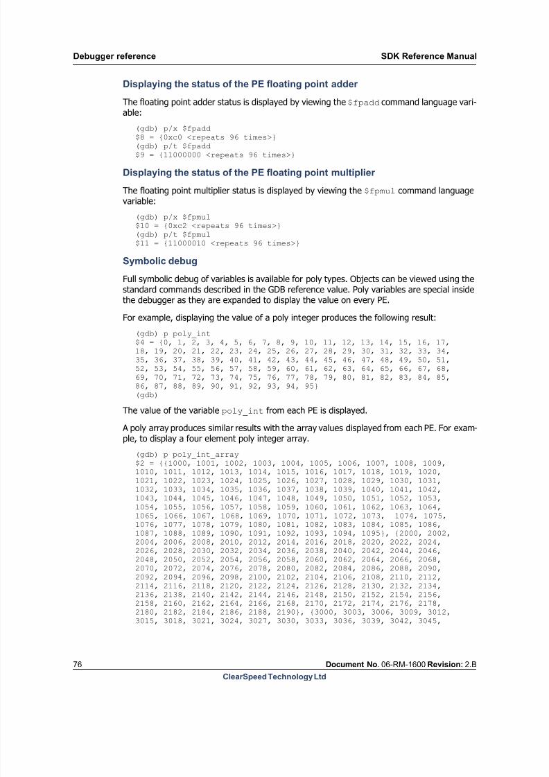
8/9/2019 SDK Reference Manual 3.1 Rev2.B
http://slidepdf.com/reader/full/sdk-reference-manual-31-rev2b 76/204
Debugger reference SDK Reference Manual
76 Document No. 06-RM-1600 Revision: 2.B
ClearSpeed Technology Ltd
Displaying the status of the PE floating point adder
The floating point adder status is displayed by viewing the $fpadd command language vari-able:
(gdb) p/x $fpadd$8 = {0xc0 <repeats 96 times>}(gdb) p/t $fpadd$9 = {11000000 <repeats 96 times>}
Displaying the status of the PE floating point multiplier
The floating point multiplier status is displayed by viewing the $fpmul command languagevariable:
(gdb) p/x $fpmul$10 = {0xc2 <repeats 96 times>}(gdb) p/t $fpmul$11 = {11000010 <repeats 96 times>}
Symbolic debug
Full symbolic debug of variables is available for poly types. Objects can be viewed using thestandard commands described in the GDB reference value. Poly variables are special insidethe debugger as they are expanded to display the value on every PE.
For example, displaying the value of a poly integer produces the following result:
(gdb) p poly_int$4 = {0, 1, 2, 3, 4, 5, 6, 7, 8, 9, 10, 11, 12, 13, 14, 15, 16, 17,18, 19, 20, 21, 22, 23, 24, 25, 26, 27, 28, 29, 30, 31, 32, 33, 34,35, 36, 37, 38, 39, 40, 41, 42, 43, 44, 45, 46, 47, 48, 49, 50, 51,52, 53, 54, 55, 56, 57, 58, 59, 60, 61, 62, 63, 64, 65, 66, 67, 68,69, 70, 71, 72, 73, 74, 75, 76, 77, 78, 79, 80, 81, 82, 83, 84, 85,
86, 87, 88, 89, 90, 91, 92, 93, 94, 95}(gdb)
The value of the variable poly_int from each PE is displayed.
A poly array produces similar results with the array values displayed from each PE. For exam-ple, to display a four element poly integer array.
(gdb) p poly_int_array$2 = {{1000, 1001, 1002, 1003, 1004, 1005, 1006, 1007, 1008, 1009,1010, 1011, 1012, 1013, 1014, 1015, 1016, 1017, 1018, 1019, 1020,1021, 1022, 1023, 1024, 1025, 1026, 1027, 1028, 1029, 1030, 1031,1032, 1033, 1034, 1035, 1036, 1037, 1038, 1039, 1040, 1041, 1042,1043, 1044, 1045, 1046, 1047, 1048, 1049, 1050, 1051, 1052, 1053,1054, 1055, 1056, 1057, 1058, 1059, 1060, 1061, 1062, 1063, 1064,1065, 1066, 1067, 1068, 1069, 1070, 1071, 1072, 1073, 1074, 1075,1076, 1077, 1078, 1079, 1080, 1081, 1082, 1083, 1084, 1085, 1086,1087, 1088, 1089, 1090, 1091, 1092, 1093, 1094, 1095}, {2000, 2002,2004, 2006, 2008, 2010, 2012, 2014, 2016, 2018, 2020, 2022, 2024,2026, 2028, 2030, 2032, 2034, 2036, 2038, 2040, 2042, 2044, 2046,2048, 2050, 2052, 2054, 2056, 2058, 2060, 2062, 2064, 2066, 2068,2070, 2072, 2074, 2076, 2078, 2080, 2082, 2084, 2086, 2088, 2090,2092, 2094, 2096, 2098, 2100, 2102, 2104, 2106, 2108, 2110, 2112,2114, 2116, 2118, 2120, 2122, 2124, 2126, 2128, 2130, 2132, 2134,2136, 2138, 2140, 2142, 2144, 2146, 2148, 2150, 2152, 2154, 2156,2158, 2160, 2162, 2164, 2166, 2168, 2170, 2172, 2174, 2176, 2178,2180, 2182, 2184, 2186, 2188, 2190}, {3000, 3003, 3006, 3009, 3012,3015, 3018, 3021, 3024, 3027, 3030, 3033, 3036, 3039, 3042, 3045,

8/9/2019 SDK Reference Manual 3.1 Rev2.B
http://slidepdf.com/reader/full/sdk-reference-manual-31-rev2b 77/204
SDK Reference Manual Debugger reference
Document No. 06-RM-1600 Revision: 2.B 77
ClearSpeed Technology Ltd
3048, 3051, 3054, 3057, 3060, 3063, 3066, 3069, 3072, 3075, 3078,3081, 3084, 3087, 3090, 3093, 3096, 3099, 3102, 3105, 3108, 3111,3114, 3117, 3120, 3123, 3126, 3129, 3132, 3135, 3138, 3141, 3144,3147, 3150, 3153, 3156, 3159, 3162, 3165, 3168, 3171, 3174, 3177,3180, 3183, 3186, 3189, 3192, 3195, 3198, 3201, 3204, 3207, 3210,
3213, 3216, 3219, 3222, 3225, 3228, 3231, 3234, 3237, 3240, 3243,3246, 3249, 3252, 3255, 3258, 3261, 3264, 3267, 3270, 3273, 3276,3279, 3282, 3285}, {4000, 4004, 4008, 4012, 4016, 4020, 4024, 4028,4032, 4036, 4040, 4044, 4048, 4052, 4056, 4060, 4064, 4068, 4072,4076, 4080, 4084, 4088, 4092, 4096, 4100, 4104, 4108, 4112, 4116,4120, 4124, 4128, 4132, 4136, 4140, 4144, 4148, 4152, 4156, 4160,4164, 4168, 4172, 4176, 4180, 4184, 4188, 4192, 4196, 4200, 4204,4208, 4212, 4216, 4220, 4224, 4228, 4232, 4236, 4240, 4244, 4248,4252, 4256, 4260, 4264, 4268, 4272, 4276, 4280, 4284, 4288, 4292,4296, 4300, 4304, 4308, 4312, 4316, 4320, 4324, 4328, 4332, 4336,4340, 4344, 4348, 4352, 4356, 4360, 4364, 4368, 4372, 4376, 4380}}(gdb)
An individual array element can be viewed as follows:
(gdb) p poly_int_array[2]$4 = {3000, 3003, 3006, 3009, 3012, 3015, 3018, 3021, 3024, 3027,3030, 3033, 3036, 3039, 3042, 3045, 3048, 3051, 3054, 3057, 3060,3063, 3066, 3069,3072, 3075, 3078, 3081, 3084, 3087, 3090, 3093,3096, 3099, 3102, 3105, 3108, 3111, 3114, 3117, 3120, 3123, 3126,3129, 3132, 3135, 3138, 3141, 3144, 3147, 3150, 3153, 3156, 3159,3162, 3165, 3168, 3171, 3174, 3177, 3180, 3183, 3186, 3189, 3192,3195, 3198, 3201, 3204, 3207, 3210, 3213, 3216, 3219, 3222, 3225,3228, 3231, 3234, 3237, 3240, 3243, 3246, 3249, 3252, 3255, 3258,3261, 3264, 3267, 3270, 3273, 3276, 3279, 3282, 3285}(gdb)
The symbolic names of poly variables can also be passed to the pex command. It uses theaddress of the variable and displays the data accordingly.
The standard GDB whatis command displays the type and multiplicity of a variable:(gdb) whatis poly_int_arraytype = poly int [4]<96 PEs>(gdb)
The information <96 PEs> describes how many elements the variable is visible over and thetype includes the poly keyword.
7.4.6 Hardware threads
csgdb has extended the threading support in GDB to allow it to debug the threads supportedby the hardware. After loading an application with multiple threads the debugger can see thestate of all threads in the system.
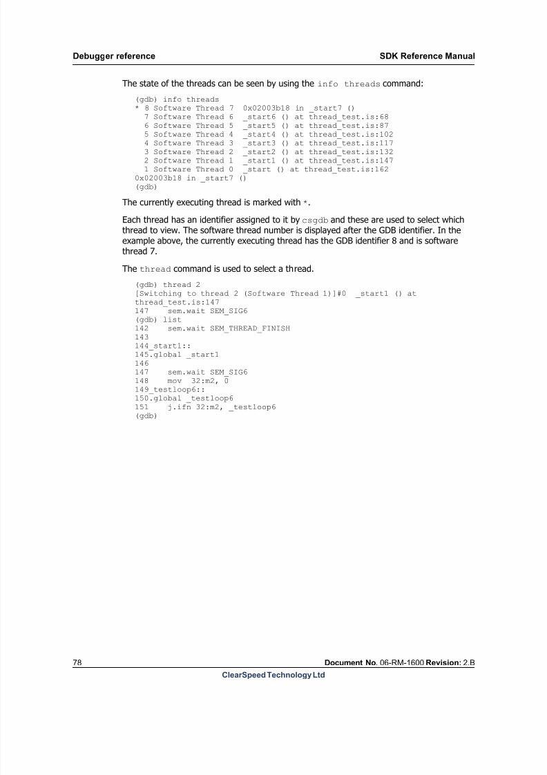
8/9/2019 SDK Reference Manual 3.1 Rev2.B
http://slidepdf.com/reader/full/sdk-reference-manual-31-rev2b 78/204
Debugger reference SDK Reference Manual
78 Document No. 06-RM-1600 Revision: 2.B
ClearSpeed Technology Ltd
The state of the threads can be seen by using the info threads command:
(gdb) info threads* 8 Software Thread 7 0x02003b18 in _start7 () 7 Software Thread 6 _start6 () at thread_test.is:68
6 Software Thread 5 _start5 () at thread_test.is:87 5 Software Thread 4 _start4 () at thread_test.is:102 4 Software Thread 3 _start3 () at thread_test.is:117 3 Software Thread 2 _start2 () at thread_test.is:132 2 Software Thread 1 _start1 () at thread_test.is:147 1 Software Thread 0 _start () at thread_test.is:1620x02003b18 in _start7 ()(gdb)
The currently executing thread is marked with *.
Each thread has an identifier assigned to it by csgdb and these are used to select whichthread to view. The software thread number is displayed after the GDB identifier. In theexample above, the currently executing thread has the GDB identifier 8 and is softwarethread 7.
The thread command is used to select a thread.
(gdb) thread 2[Switching to thread 2 (Software Thread 1)]#0 _start1 () atthread_test.is:147147 sem.wait SEM_SIG6(gdb) list142 sem.wait SEM_THREAD_FINISH143144_start1::145.global _start1146147 sem.wait SEM_SIG6148 mov 32:m2, 0
149_testloop6::150.global _testloop6151 j.ifn 32:m2, _testloop6(gdb)
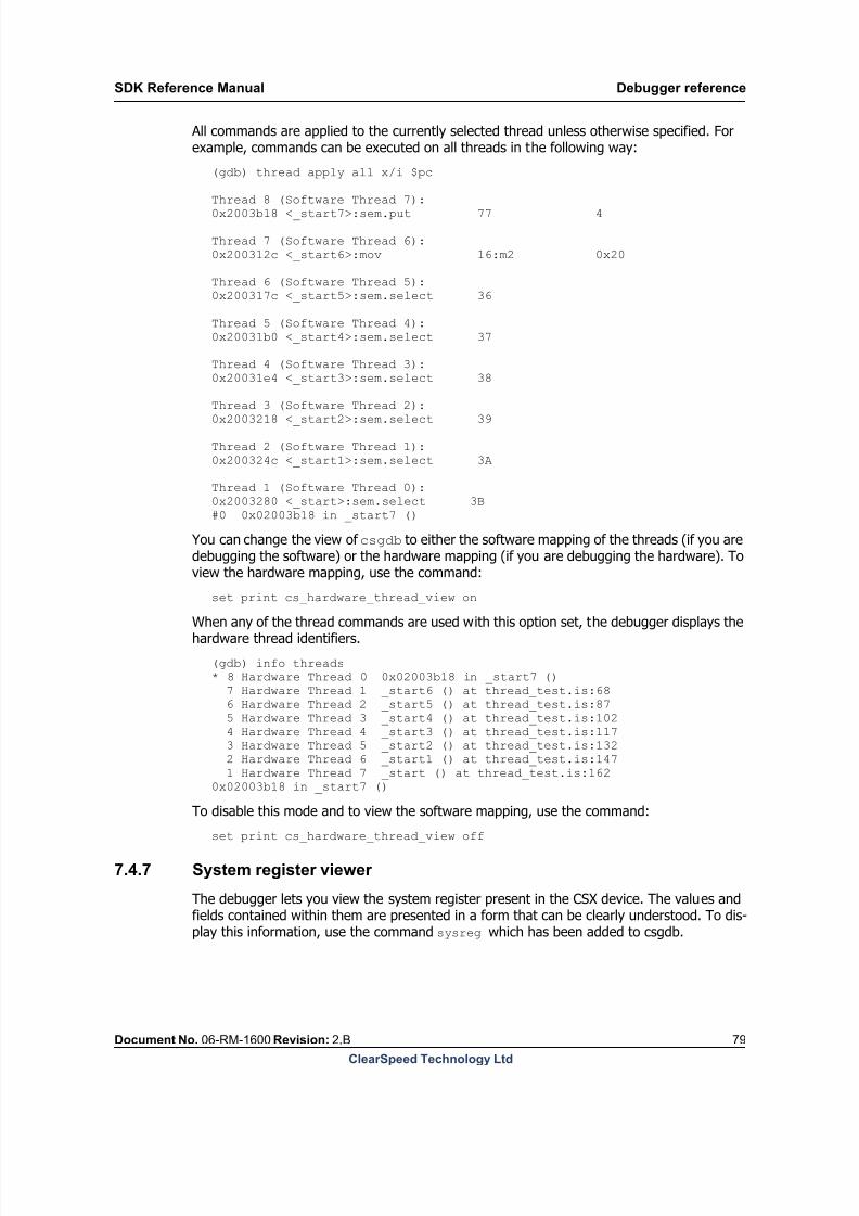
8/9/2019 SDK Reference Manual 3.1 Rev2.B
http://slidepdf.com/reader/full/sdk-reference-manual-31-rev2b 79/204
SDK Reference Manual Debugger reference
Document No. 06-RM-1600 Revision: 2.B 79
ClearSpeed Technology Ltd
All commands are applied to the currently selected thread unless otherwise specified. Forexample, commands can be executed on all threads in the following way:
(gdb) thread apply all x/i $pc
Thread 8 (Software Thread 7):0x2003b18 <_start7>:sem.put 77 4
Thread 7 (Software Thread 6):0x200312c <_start6>:mov 16:m2 0x20
Thread 6 (Software Thread 5):0x200317c <_start5>:sem.select 36
Thread 5 (Software Thread 4):0x20031b0 <_start4>:sem.select 37
Thread 4 (Software Thread 3):0x20031e4 <_start3>:sem.select 38
Thread 3 (Software Thread 2):0x2003218 <_start2>:sem.select 39
Thread 2 (Software Thread 1):0x200324c <_start1>:sem.select 3A
Thread 1 (Software Thread 0):0x2003280 <_start>:sem.select 3B#0 0x02003b18 in _start7 ()
You can change the view of csgdb to either the software mapping of the threads (if you aredebugging the software) or the hardware mapping (if you are debugging the hardware). Toview the hardware mapping, use the command:
set print cs_hardware_thread_view on
When any of the thread commands are used with this option set, the debugger displays thehardware thread identifiers.
(gdb) info threads* 8 Hardware Thread 0 0x02003b18 in _start7 () 7 Hardware Thread 1 _start6 () at thread_test.is:68 6 Hardware Thread 2 _start5 () at thread_test.is:87 5 Hardware Thread 3 _start4 () at thread_test.is:102 4 Hardware Thread 4 _start3 () at thread_test.is:117 3 Hardware Thread 5 _start2 () at thread_test.is:132 2 Hardware Thread 6 _start1 () at thread_test.is:147 1 Hardware Thread 7 _start () at thread_test.is:1620x02003b18 in _start7 ()
To disable this mode and to view the software mapping, use the command:set print cs_hardware_thread_view off
7.4.7 System register viewer
The debugger lets you view the system register present in the CSX device. The values andfields contained within them are presented in a form that can be clearly understood. To dis-play this information, use the command sysreg which has been added to csgdb.
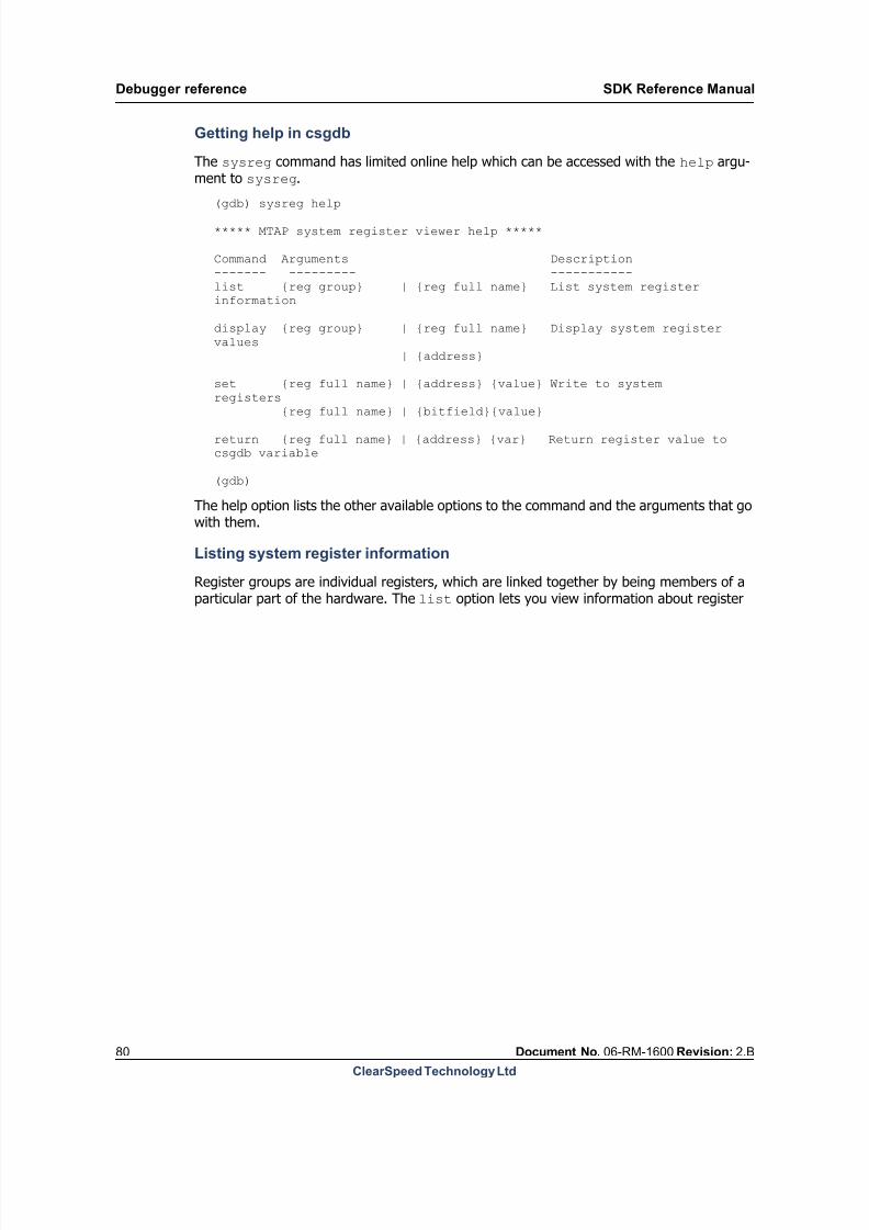
8/9/2019 SDK Reference Manual 3.1 Rev2.B
http://slidepdf.com/reader/full/sdk-reference-manual-31-rev2b 80/204
Debugger reference SDK Reference Manual
80 Document No. 06-RM-1600 Revision: 2.B
ClearSpeed Technology Ltd
Getting help in csgdb
The sysreg command has limited online help which can be accessed with the help argu-ment to sysreg.
(gdb) sysreg help
***** MTAP system register viewer help *****
Command Arguments Description------- --------- -----------list {reg group} | {reg full name} List system registerinformation display {reg group} | {reg full name} Display system registervalues | {address}
set {reg full name} | {address} {value} Write to systemregisters
{reg full name} | {bitfield}{value}
return {reg full name} | {address} {var} Return register value tocsgdb variable (gdb)
The help option lists the other available options to the command and the arguments that gowith them.
Listing system register information
Register groups are individual registers, which are linked together by being members of aparticular part of the hardware. The list option lets you view information about register

8/9/2019 SDK Reference Manual 3.1 Rev2.B
http://slidepdf.com/reader/full/sdk-reference-manual-31-rev2b 81/204
SDK Reference Manual Debugger reference
Document No. 06-RM-1600 Revision: 2.B 81
ClearSpeed Technology Ltd
groups, registers contained within the groups and the bit field information for individual reg-isters. For example, to get a list of all register groups use the list option with no arguments.
(gdb) sysreg list
System register group list :
Group Name----------CCBRSCCBRS_P0CCBRS_P1ISUISU_GIUISU_GSUISU_IGLMILMI_DMALMI_DMA_AEULMI_LMICOM
LMI_LMIRIFLMI_LMISRVMTAPMTAP_ACMTAP_AC_DBMTAP_AC_DB_CMMTAP_AC_ITMTAP_AC_MSMTAP_GPIOC0MTAP_GPIOC0_GPIOCMTAP_GPIOE0MTAP_GPIOE0_GPIOEMTAP_TSCMTAP_TSC_ICACHEMTAP_TSC_ICACHE_IBUFFER
MTAP_TSC_LSUMTAP_TSC_SCHEDMTAP_TSC_SEMMTAP_TSC_TPMTAP_TSC_TP_DPMTAP_TSC_TP_TPREGSYS
(gdb)
This command lists all the available register groups that are visible to the debugger.
Viewing information about a register group
You can view the contents of the register groups themselves by passing the name of thegroup with the list argument. The register group names are displayed when you use thelist argument on its own.

8/9/2019 SDK Reference Manual 3.1 Rev2.B
http://slidepdf.com/reader/full/sdk-reference-manual-31-rev2b 82/204
Debugger reference SDK Reference Manual
82 Document No. 06-RM-1600 Revision: 2.B
ClearSpeed Technology Ltd
For example, to display the contents of the MTAP_TSC_SCHED group, enter the following com-mand:
(gdb) sysreg list MTAP_TSC_SCHED
System register list for group MTAP_TSC_SCHED :
Register Name-------------CONTROLSTATUSSWITCH_THREAD
(gdb)
This lists the register names that are contained within the group.
Listing the information about a specific register
The list option also lets you display information about a specific register and by passing
the full register name (in the format group name) along with the list argument.
For example, to view the information for the STATUS register of the MTAP_TSC_SCHED
group:
(gdb) sysreg list MTAP_TSC_SCHED STATUS
System register definition--------------------------Name : STATUSGroup : MTAP_TSC_SCHEDDescription : Status of each threadReset Value : 255Address : 0x102
Bit Fields----------Name : READYFirst : 0Last : 7Width : 8
Name : THREADFirst : 16Last : 18Width : 3
Name : YIELDFirst : 8Last : 15Width : 8
(gdb)
This command lists the definition and bit field information for the requested register.
Displaying system register values
As well as displaying the information regarding the make up of each of the groups and reg-isters, it is possible to display the values contained within them. The values can be displayedat a group level or also at an individual register level to allow the bit-field values to be dis-played. This is done by using the display argument to the sysreg command.

8/9/2019 SDK Reference Manual 3.1 Rev2.B
http://slidepdf.com/reader/full/sdk-reference-manual-31-rev2b 83/204
SDK Reference Manual Debugger reference
Document No. 06-RM-1600 Revision: 2.B 83
ClearSpeed Technology Ltd
Displaying the values of a register group
The values of all registers contained within a register group can be displayed using the dis-play argument with a valid register group name. For example:
(gdb) sysreg display MTAP_TSC_SCHED
System register display for group MTAP_TSC_SCHED :
Register Name Value------------- -----CONTROL 0x8STATUS 0x70000SWITCH_THREAD 0x7
(gdb)
Displaying the value of an individual register
The value of a register can be displayed by passing a valid register name or hex address with
the display argument. For example:
(gdb) sysreg display MTAP_TSC_SCHED STATUS
System register display for MTAP_TSC_SCHED_STATUS :
Value : 0x70000 0b00000000000001110000000000000000
Bit Fields Value---------- -----READY 0x0THREAD 0x7YIELD 0x0
(gdb)
Returning a register value to a GDB variable
The return option lets you store the value of a register in a GDB variable for use in a script.
The following example prints the value of register MTAP_TSC_TPREG_REGISTER_R1 through the GDB variable $regval:
(gdb) sysreg return MTAP_TSC_TPREG_REGISTER_R1 regval(gdb) print $regval
Writing to registers
The set option lets you write values to system registers.
Full register names or hex addresses can be specified. As well as writing to whole registers,valid bit field names can be specified when only part of a register requires writing to.
(gdb) set MTAP_TSC_TPREG_REGISTER_R1 123(gdb) set 06700A84 123
7.4.8 TSC semaphore viewer
Semaphores are used to synchronize code running on the CSX processor and the host. Thesesemaphores are in the Thread Sequence Controller (TSC) of the CSX processor. The debug-

8/9/2019 SDK Reference Manual 3.1 Rev2.B
http://slidepdf.com/reader/full/sdk-reference-manual-31-rev2b 84/204
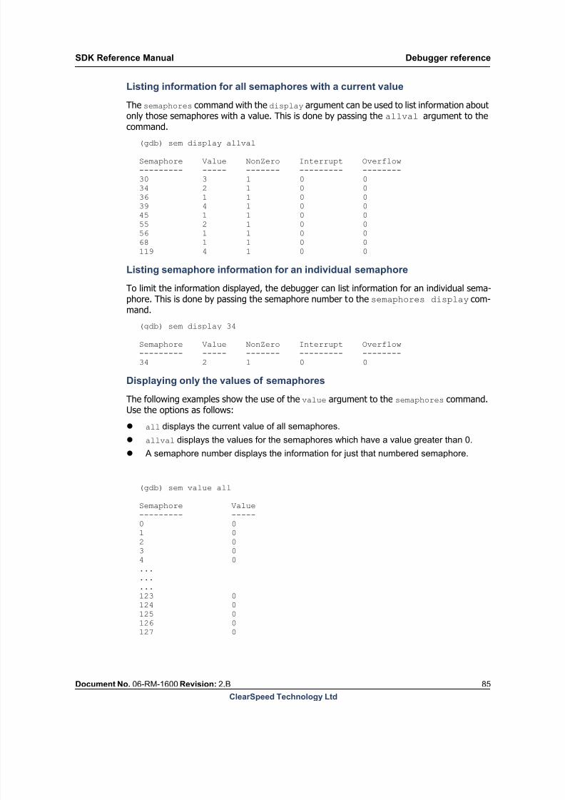
8/9/2019 SDK Reference Manual 3.1 Rev2.B
http://slidepdf.com/reader/full/sdk-reference-manual-31-rev2b 85/204
SDK Reference Manual Debugger reference
Document No. 06-RM-1600 Revision: 2.B 85
ClearSpeed Technology Ltd
Listing information for all semaphores with a current value
The semaphores command with the display argument can be used to list information aboutonly those semaphores with a value. This is done by passing the allval argument to thecommand.
(gdb) sem display allval
Semaphore Value NonZero Interrupt Overflow--------- ----- ------- --------- --------30 3 1 0 034 2 1 0 036 1 1 0 039 4 1 0 045 1 1 0 055 2 1 0 056 1 1 0 068 1 1 0 0119 4 1 0 0
Listing semaphore information for an individual semaphore
To limit the information displayed, the debugger can list information for an individual sema-phore. This is done by passing the semaphore number to the semaphores display com-mand.
(gdb) sem display 34
Semaphore Value NonZero Interrupt Overflow--------- ----- ------- --------- --------34 2 1 0 0
Displaying only the values of semaphores
The following examples show the use of the value argument to the semaphores command.Use the options as follows:
all displays the current value of all semaphores.
allval displays the values for the semaphores which have a value greater than 0.
A semaphore number displays the information for just that numbered semaphore.
(gdb) sem value all
Semaphore Value--------- -----0 0
1 02 03 04 0.........123 0124 0125 0126 0127 0

8/9/2019 SDK Reference Manual 3.1 Rev2.B
http://slidepdf.com/reader/full/sdk-reference-manual-31-rev2b 86/204
Debugger reference SDK Reference Manual
86 Document No. 06-RM-1600 Revision: 2.B
ClearSpeed Technology Ltd
(gdb) sem value allval
Semaphore Value--------- -----30 3
34 236 139 445 155 256 168 1119 4
(gdb) sem value 30
Semaphore Value--------- -----30 3
Displaying only the nonzero status of the semaphores
The debugger can list the nonzero status of each of the semaphores. This is done by passingthe nonzero option to the semaphores command. The arguments that work with thenonzero option are:
all to list the nonzero fields for all semaphores.
allnon to list just those with values in the nonzero field.
An individual semaphore number.
(gdb) sem nonzero all
Semaphore NonZero--------- -------0 11 12 13 14 1.........123 1124 1125 1126 1127 0
(gdb) sem nonzero allnon
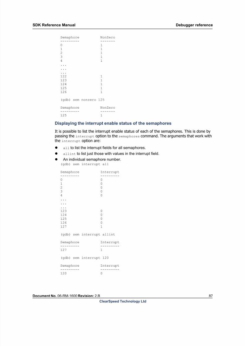
8/9/2019 SDK Reference Manual 3.1 Rev2.B
http://slidepdf.com/reader/full/sdk-reference-manual-31-rev2b 87/204
SDK Reference Manual Debugger reference
Document No. 06-RM-1600 Revision: 2.B 87
ClearSpeed Technology Ltd
Semaphore NonZero--------- -------0 11 12 1
3 14 1.........122 1123 1124 1125 1126 1
(gdb) sem nonzero 125
Semaphore NonZero--------- -------
125 1
Displaying the interrupt enable status of the semaphores
It is possible to list the interrupt enable status of each of the semaphores. This is done bypassing the interrupt option to the semaphores command. The arguments that work withthe interrupt option are:
all to list the interrupt fields for all semaphores.
allint to list just those with values in the interrupt field.
An individual semaphore number.(gdb) sem interrupt all
Semaphore Interrupt--------- ---------0 01 02 03 04 0.........123 0124 0125 0126 0127 1
(gdb) sem interrupt allint
Semaphore Interrupt--------- ---------127 1
(gdb) sem interrupt 120
Semaphore Interrupt--------- ---------120 0

8/9/2019 SDK Reference Manual 3.1 Rev2.B
http://slidepdf.com/reader/full/sdk-reference-manual-31-rev2b 88/204
Debugger reference SDK Reference Manual
88 Document No. 06-RM-1600 Revision: 2.B
ClearSpeed Technology Ltd
Displaying the overflow status of the semaphores
The debugger can display the overflow status of each of the semaphores. This is done by
passing the overflow option to the semaphores command. The arguments that work withthe overflow option are:
all to list the overflow fields for all semaphores.
allovr to list just those with values in the overflow field.
An individual semaphore number.
(gdb) sem overflow all
Semaphore Overflow--------- --------0 0
1 02 03 04 0.........123 0124 0125 0126 0127 0
(gdb) sem overflow allovr
Semaphore Overflow--------- --------10 118 1123 1
(gdb) sem overflow 20
Semaphore Overflow--------- --------20 0
Displaying the current thread / semaphore usage
It is also possible to view the semaphore usage for the TSC threads so that you can see whichsemaphore number is currently selected. This is done using the thread argument to the
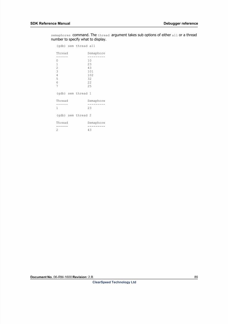
8/9/2019 SDK Reference Manual 3.1 Rev2.B
http://slidepdf.com/reader/full/sdk-reference-manual-31-rev2b 89/204
SDK Reference Manual Debugger reference
Document No. 06-RM-1600 Revision: 2.B 89
ClearSpeed Technology Ltd
semaphores command. The thread argument takes sub options of either all or a threadnumber to specify what to display.
(gdb) sem thread all
Thread Semaphore------ ---------0 101 232 433 1014 1025 326 227 25
(gdb) sem thread 1
Thread Semaphore------ ---------
1 23
(gdb) sem thread 2
Thread Semaphore------ ---------2 43
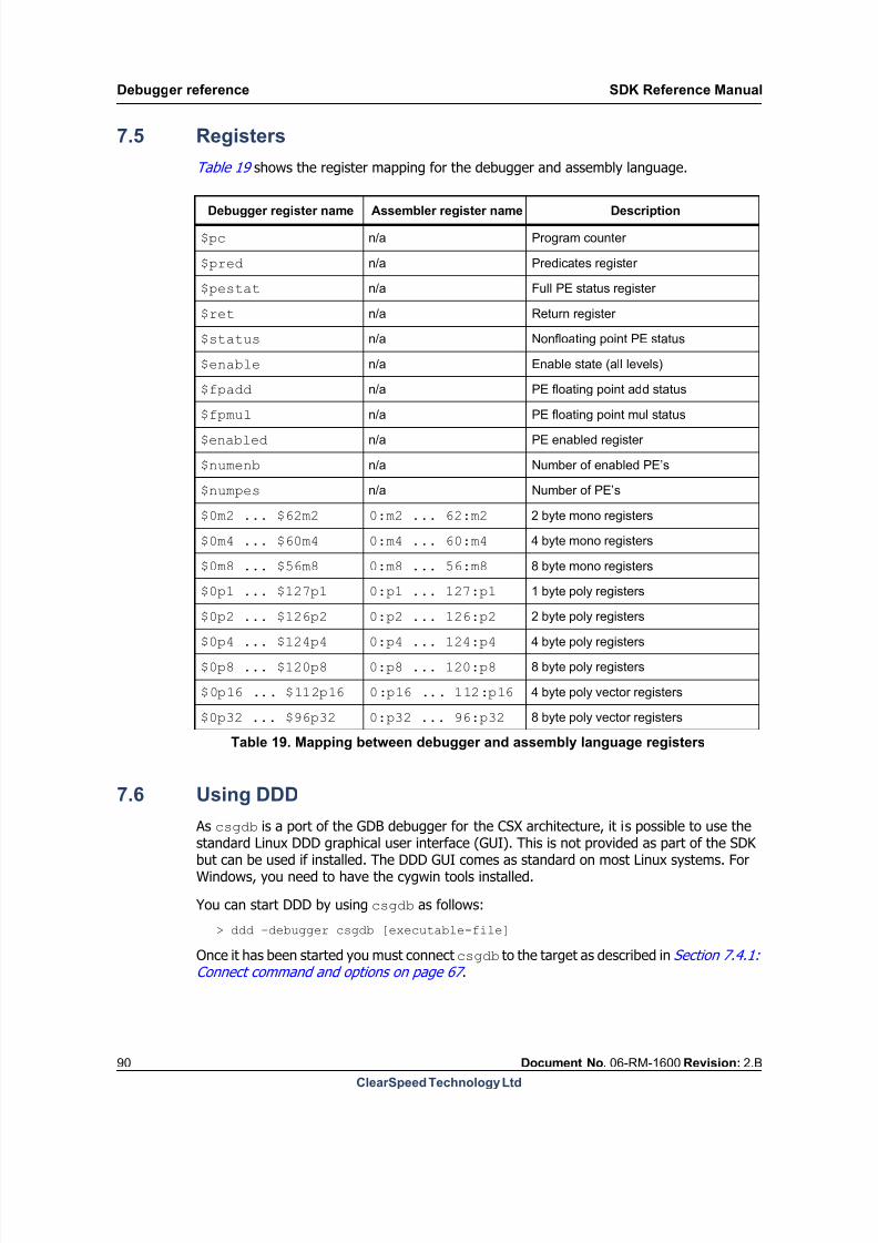
8/9/2019 SDK Reference Manual 3.1 Rev2.B
http://slidepdf.com/reader/full/sdk-reference-manual-31-rev2b 90/204
Debugger reference SDK Reference Manual
90 Document No. 06-RM-1600 Revision: 2.B
ClearSpeed Technology Ltd
7.5 Registers
Table 19 shows the register mapping for the debugger and assembly language.
7.6 Using DDD
As csgdb is a port of the GDB debugger for the CSX architecture, it is possible to use thestandard Linux DDD graphical user interface (GUI). This is not provided as part of the SDKbut can be used if installed. The DDD GUI comes as standard on most Linux systems. ForWindows, you need to have the cygwin tools installed.
You can start DDD by using csgdb as follows:
> ddd –debugger csgdb [executable-file]
Once it has been started you must connect csgdb to the target as described in Section 7.4.1:Connect command and options on page 67 .
Debugger register name Assembler register name Description
$pc n/a Program counter
$pred n/a Predicates register
$pestat n/a Full PE status register
$ret n/a Return register
$status n/a Nonfloating point PE status
$enable n/a Enable state (all levels)
$fpadd n/a PE floating point add status
$fpmul n/a PE floating point mul status
$enabled n/a PE enabled register
$numenb n/a Number of enabled PE’s
$numpes n/a Number of PE’s
$0m2 ... $62m2 0:m2 ... 62:m2 2 byte mono registers
$0m4 ... $60m4 0:m4 ... 60:m4 4 byte mono registers
$0m8 ... $56m8 0:m8 ... 56:m8 8 byte mono registers
$0p1 ... $127p1 0:p1 ... 127:p1 1 byte poly registers
$0p2 ... $126p2 0:p2 ... 126:p22 byte poly registers
$0p4 ... $124p4 0:p4 ... 124:p4 4 byte poly registers
$0p8 ... $120p8 0:p8 ... 120:p8 8 byte poly registers
$0p16 ... $112p16 0:p16 ... 112:p16 4 byte poly vector registers
$0p32 ... $96p32 0:p32 ... 96:p32 8 byte poly vector registers
Table 19. Mapping between debugger and assembly language registers

8/9/2019 SDK Reference Manual 3.1 Rev2.B
http://slidepdf.com/reader/full/sdk-reference-manual-31-rev2b 91/204
SDK Reference Manual Debugger reference
Document No. 06-RM-1600 Revision: 2.B 91
ClearSpeed Technology Ltd
After this you can set a breakpoint and select [Run] in DDD. You can then debug the appli-cation using the GUI front end.

8/9/2019 SDK Reference Manual 3.1 Rev2.B
http://slidepdf.com/reader/full/sdk-reference-manual-31-rev2b 92/204

8/9/2019 SDK Reference Manual 3.1 Rev2.B
http://slidepdf.com/reader/full/sdk-reference-manual-31-rev2b 93/204
SDK Reference Manual Simulators reference
Document No. 06-RM-1600 Revision: 2.B 93
ClearSpeed Technology Ltd
8.2.1 Command line options for isim
The command-line options may be specified in any order.
-p filename
--profile filename
The -p option enables profiling in the simulator and specifies the filename that profiling datais to be written to. See Section Section 8.5: Profiling on page 96 for more information.
Note: This profile information is not compatible with the ClearSpeed Visual Profiler.
-c filename
--csx filename
The --csx option can be used in conjunction with the profiling option to provide the simu-lator with the name of the file being simulated so it can extract more detailed profiling infor-mation.
-q --quiet
This option turns off the display of the cycle count while the simulator is running. This maybe useful if the verbose option is used.
--max-cycle integer
Long nameShort
nameValid values Description
--profile -p filenameSpecifies the file that profiling information will
be written to
--csx -c filenameSpecifies the file which provides extra
information about the program that is being
profiled
--quiet -qSuppress the display of cycle counts while the
simulator is running
--max-cycle integer Specifies an upper limit to the simulation
speed.
--strict-mem-alignment
Enforces checking of memory alignment,register alignment or both--strict-reg-alignment
--strict-alignment
--mem-warnEnable memory warnings e.g. poly out of
bounds and uninitiated mono reads
--display-while-idle Update cycle counters while idling
--instance -i integer Instance number of simulator.
--ram-size -r integer DRAM size in MBytes (default 512 MB)
--processor-type Defines processor type as CSX600 or CSX700
Table 20. Summary of isim command-line options
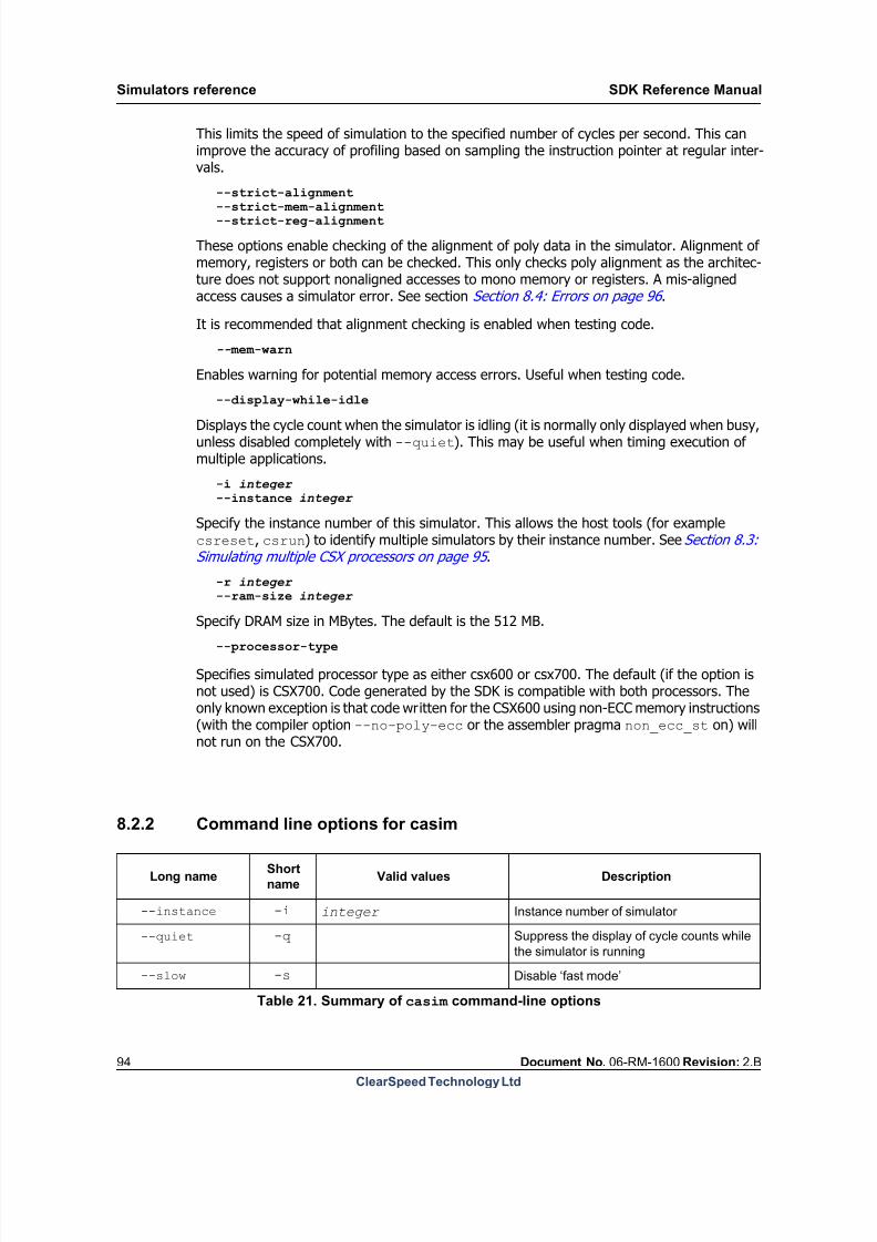
8/9/2019 SDK Reference Manual 3.1 Rev2.B
http://slidepdf.com/reader/full/sdk-reference-manual-31-rev2b 94/204
Simulators reference SDK Reference Manual
94 Document No. 06-RM-1600 Revision: 2.B
ClearSpeed Technology Ltd
This limits the speed of simulation to the specified number of cycles per second. This canimprove the accuracy of profiling based on sampling the instruction pointer at regular inter-vals.
--strict-alignment
--strict-mem-alignment --strict-reg-alignment
These options enable checking of the alignment of poly data in the simulator. Alignment ofmemory, registers or both can be checked. This only checks poly alignment as the architec-ture does not support nonaligned accesses to mono memory or registers. A mis-alignedaccess causes a simulator error. See section Section 8.4: Errors on page 96 .
It is recommended that alignment checking is enabled when testing code.
-- mem-warn
Enables warning for potential memory access errors. Useful when testing code.
--display-while-idle
Displays the cycle count when the simulator is idling (it is normally only displayed when busy,unless disabled completely with --quiet). This may be useful when timing execution ofmultiple applications.
-i integer
--instance integer
Specify the instance number of this simulator. This allows the host tools (for examplecsreset, csrun) to identify multiple simulators by their instance number. See Section 8.3:Simulating multiple CSX processors on page 95 .
-r integer
--ram-size integer
Specify DRAM size in MBytes. The default is the 512 MB.--processor-type
Specifies simulated processor type as either csx600 or csx700. The default (if the option isnot used) is CSX700. Code generated by the SDK is compatible with both processors. Theonly known exception is that code written for the CSX600 using non-ECC memory instructions(with the compiler option --no-poly-ecc or the assembler pragma non_ecc_st on) willnot run on the CSX700.
8.2.2 Command line options for casim
Long nameShort
nameValid values Description
--instance -i integer Instance number of simulator
--quiet -q Suppress the display of cycle counts while
the simulator is running
--slow -s Disable ‘fast mode’
Table 21. Summary of casim command-line options

8/9/2019 SDK Reference Manual 3.1 Rev2.B
http://slidepdf.com/reader/full/sdk-reference-manual-31-rev2b 95/204
SDK Reference Manual Simulators reference
Document No. 06-RM-1600 Revision: 2.B 95
ClearSpeed Technology Ltd
-i integer
--instance integer
Specify the instance number of this simulator. This allows the host tools (for examplecsreset or csrun) to identify multiple simulators by their instance number. SeeSection 8.3: Simulating multiple CSX processors on page 95 .
-q
--quiet
This option turns off the display of the cycle count while the simulator is running. This maybe useful if the verbose option is used.
--slow-s
Normally casim runs in “fast mode” where as much cycle-accurate behavior as possible is disabled
when the processor is idle. This means, for example, that the performance counters are disabled when
no code is running. If it is important for the performance counters to be cycle accurate when idling then
the --slow option can be used. This may be important when simulating multiple CSX processor
cores if one of them could be idle while the others are running.
-trace filename-T filename
This enables profile trace information output to the file filename. The profile trace file can be readby the ClearSpeed Visual Profiler to give details of the timing of instruction pipelining andissue. See Section 8.5: Profiling on page 96 .
--processor-type
Specifies simulated processor type as either csx600 or csx700. The default (if the option is
not used) is CSX700. Code generated by the SDK is compatible with both processors. The
only known exception is that code written for the CSX600 using non-ECC memory
instructions (with the compiler option --no-poly-ecc or the assembler pragma
non_ecc_st on) will not run on the CSX700.
8.3 Simulating multiple CSX processors
When simulating multiboard systems, each simulator can be thought of as a single PCI boardcontaining two processors. Individual boards or simulators are distinguished by their zero-based instance numbers. The host application can also be parametrized with an instancenumber so that unique simulator-application communication mappings can be established.
For example, two simulators could be started as follows (in separate command shells):
isim -i 1
isim -i 2
--trace -T filename Enable profiling trace information output to
file.
--processor-typeDefines processor type as CSX600 or
CSX700
Long nameShort
nameValid values Description
Table 21. Summary of casim command-line options (Continued)
8/9/2019 SDK Reference Manual 3.1 Rev2.B
http://slidepdf.com/reader/full/sdk-reference-manual-31-rev2b 96/204
Simulators reference SDK Reference Manual
96 Document No. 06-RM-1600 Revision: 2.B
ClearSpeed Technology Ltd
Then the corresponding host applications would run as shown below:
csreset --sim -i 1csreset --sim -i 2
csrun --sim -i 1 ./first.csx
csrun --sim -i 2 ./second.csxNote that the --sim option tells the host tool to communicate with a simulator, instead of aboard.
8.4 Errors
If isim tries to execute an instruction which it does not understand, or is unable to completean instruction correctly, it will stop and display an error message along with the programcounter of the instruction it was attempting to execute. The simulator will continue runningand can load and run further programs. It is only the code currently being simulated that willhalt.
If casim executes an illegal instruction or an instruction with illegal or out-of-bounds oper-ands, it will issue a warning message and continue execution of the program as would occuron the hardware. Depending on the nature of the instruction, it may be ignored or it maytrigger a series of further error or warning messages if the processor state has beenadversely affected. This is useful in debugging code, for example, where illegal memoryaddresses have been generated, which would cause real hardware to hang.
8.5 Profiling
casim is a cycle-accurate simulator (or near cycle-accurate, as some small differencesbetween casim and real hardware do exist). It has been designed to work in conjunction
with ClearSpeed Visual Profiler in two ways:
1. The first is directly, via the built-in monitor ports accessible from the host, in the same
manner as that possible with real hardware (the process for connecting profiler to
hardware or a simulator is described in [5]: ClearSpeed Visual Profiler User Guide).
2. The second is by enabling the production of extended profile trace data, dumped to a
file that the profiler can read. Using this second method, much more detail about
instruction issue and pipelining is available form casim than is available by connecting
directly to hardware. This process is described in the next section.
8.5.1 Profiler trace file production on casim
casim has been designed to output profiling trace information that can be read by theClearSpeed Visual Profiler. The trace file contains detailed instruction issue and pipelininginformation allowing the programmer to analyse inefficiencies in the code execution and tooptimize the overlap of I/O and compute to achieve maximum application performance.
Much more detailed information is available form the casim trace file than is available bydirectly connecting the profiler to the hardware.
Tracing is enabled by the --trace (-T) command-line option. This takes a parameter whichspecifies the file the trace information is to be written to. For example:
casim -T my_trace.dat

8/9/2019 SDK Reference Manual 3.1 Rev2.B
http://slidepdf.com/reader/full/sdk-reference-manual-31-rev2b 97/204
SDK Reference Manual Simulators reference
Document No. 06-RM-1600 Revision: 2.B 97
ClearSpeed Technology Ltd
This will create a file named my_trace.dat and output profile tracing information to it,when enabled.
Once enabled the output of trace information to the file is controlled by special instructionsinserted into executable code via the debugger connected to the simulation. This allows the
user to control the portion of code to be profiled. See [5]: ClearSpeed Visual Profiler UserGuide for details.
The resulting trace file is read by the ClearSpeed Visual Profiler to produce a detailed graph-ical representation of the progress of instruction pipes. The file is not intended to be readmanually. However, for reference, an example of the trace file output format is shown inFigure 9 , with a key shown in Table 22 .
C 0x6503aTS 0 0x00000014 7C 0x6503bI2 0 0x00200000 7I1 0 0x00000011 7I0 0 0x881c0945 7 0x2013184
TS 0 0x00000010 7M 0 0xb08d0200 0x1A 0 0xb08d0000L 0 0xa6180102 0x2
Figure 9.casim profile trace file format
The cycle count (C) line is output every cycle. The count field for M, L and P codes gives
the number of cycles that these multi-cycle opcodes have been in the issue stage.
Event Code Fields
Cycle count C cycle_count
TSC stall flag info TS processor_id stall info bit field thread
Opcode in INST0 with PC I0 processor_id opcode thread pc
Opcode in INST1 I1 processor_id opcode thread
Opcode in INST2 I2 processor_id opcode thread
Opcode in AC preprocessing A processor_id opcode
Opcode in microcode issue M processor_id opcode count
Opcode in load/store issue L processor_id opcode count
Opcode in PIO controller issue P processor_id opcode count
Table 22. casim trace file key

8/9/2019 SDK Reference Manual 3.1 Rev2.B
http://slidepdf.com/reader/full/sdk-reference-manual-31-rev2b 98/204
Simulators reference SDK Reference Manual
98 Document No. 06-RM-1600 Revision: 2.B
ClearSpeed Technology Ltd
The TSC stall flag (TS) is output whenever there is a stall. The format of the stall info bit fieldfield of the TS trace message is shown in Table 23 .
8.6 Instruction profiling on isim
As isim is not cycle-accurate, accurate profiling as described above for casim is not possible.However, isim does accurately model instruction execution and the facility exists to profilethis, allowing reasonable estimates to be made of code performance.
Note: This profile information is not the same as the trace information generated by casim and is not compatible with the ClearSpeed Visual Profiler.
To run a program on isim with profiling enabled, the --profile (-p) command-line optionshould be used. This indicates the output file to which the profiling results are written. Forexample:
isim -p prof.vpr
This will create a file named prof.vpr (in the directory where isim is invoked) and outputprofiling information to it. This information is text based and is suitable for loading into a
stall info
bit field value
Stall flag Description
1 (bit 0) FULLDown-stream controller issue pipe is full (a normal
condition when the controller is busy).
2 (bit 1) SEM Semaphore unit is busy (should be a very short stall).
4 (bit 2) READY
From scheduler: this bit is reset when instruction pipeline
is stalled due to other flags, e.g. FULL or if scheduler is
waiting on a semaphore.
8 (bit 3) LOAD_STOREMono load-store stall (try doing bigger loads and stalls to
amortize cost).
16 (bit 4) ICACHE_MISS Four cycles if buffer miss only, more if a full Icache miss.
32 (bit 5) INST0_ALUOP Mono ALU is stalled due to latency of consecutivesemaphore select operations
64 (bit 6) MULTI-CYCLE-ALUOPMulti-cycle mono ALU op, for example, mul, mulfp, and
so on.
128 (bit 7) IBAU not used
256 (bit 8) WRITE-RESULTWriting a result register is not bypassed so a stall is
required.
Table 23. casim profile trace TSC stall event key

8/9/2019 SDK Reference Manual 3.1 Rev2.B
http://slidepdf.com/reader/full/sdk-reference-manual-31-rev2b 99/204
SDK Reference Manual Simulators reference
Document No. 06-RM-1600 Revision: 2.B 99
ClearSpeed Technology Ltd
spreadsheet for analysis, as all the fields are tab separated. An example of the output isshown in Figure 10 .
Tsc Ac Pio ThreadInstruction...1 Non Non 12018c70 add 32:m2, 32:m2, 0x801 8 Non 1 2018c74st 32:m2, 0:p321 8 Non 1 2018c78
Figure 10.Example isim profiling information
The first three fields are the number of cycles the instruction takes to execute in the TSC(mono processor), AC (Array Controller), and PIO (Programmed I/O controller). “Non” indi-cates that the instruction is not executed on that controller. The fourth field is the thread IDand the remaining fields are the program counter, the instruction name and its arguments.
If the --csx option is used, the output will include more information, as shown in Figure 11 .
Tsc Ac Pio Thread Instruction
... _async_redirect1 1 Non 1 2006530 st 0:m4 32:m16135 async_io_asm.is1 1 Non 1 2006534 sem.select 77 139async_io_asm.is1 1 Non 1 2006538 sem.wait.selected 139async_io_asm.is1 1 Non 1 200653C mono.immed 0x3040 141
Figure 11.Extended isim profiling information
This format includes the following extra fields: labels from the source file and the line numberand file name (last two fields) of the source file that the code was created from.

8/9/2019 SDK Reference Manual 3.1 Rev2.B
http://slidepdf.com/reader/full/sdk-reference-manual-31-rev2b 100/204
Archiver SDK Reference Manual
100 Document No. 06-RM-1600 Revision: 2.B
ClearSpeed Technology Ltd
9 Archiver
This archiver program combines several object files into a ClearSpeed library file. It takes the
place of the GNU archiver, ar, or the Microsoft lib program. Some libraries are provided aspart of the SDK, these can be found in the lib directory of the SDK installation. The con-ventional extension for these files is .csa.
9.1 Invoking the archiver
The archiver takes a list of object files and generates an output library file or archive. Thelibrary name must be specified by using the -o option. The linker command is:
arcs [option]* -o lib_file input_files
For example, the following command will combine the object files foo.cso and bar.cso
to generate the archive file foo.csa in the same directory:arcs -o foo.csa foo.cso bar.cso
9.2 Command-line options
As well as the common command-line options defined in Chapter 1: SDK overview , the com-piler has its own set of specific options. These are summarized in Table 24 .
--output-o
lib_name--extract -x
--toc -t
-o library
--output library
Specifies the output file name for the library. This option must be used to specify the libraryfile name. One or more object files must also be specified.
--extract
-x
Extracts object files contained in the archive and puts them in the current directory.
--toc
-t
Displays the contents of the archive file.
Long nameShort
nameValid values Description
The name of the library file to be created
Extracts object files from the archive.
Displays the contents of the archive.
Table 24. Standard command-line options

8/9/2019 SDK Reference Manual 3.1 Rev2.B
http://slidepdf.com/reader/full/sdk-reference-manual-31-rev2b 101/204
SDK Reference Manual Object file dump
Document No. 06-RM-1600 Revision: 2.B 101
ClearSpeed Technology Ltd
10 Object file dump
The object dump tool, csdump, is a useful utility for inspecting the contents of object files.
It is similar to the standard unix objdump program. The standard objdump can be used withClearSpeed object files as they are based on the ELF standard. However, csdump adds somefeatures of specific relevance to ClearSpeed object files.
10.1 Invoking csdump
The object dump tool takes an object file and displays information about the contents. All theoutput from csdump is sent to standard output, unless otherwise specified. The commandline is:
csdump [option]* file_name
If invoked without any options, csdump generates a full dump of the file, dividing it into sec-tions and, where applicable, disassembling the code. If the relocation section is present inthe file, the relocations are overlaid onto the disassembly. Both object and executable filescan be inspected with csdump.
10.2 Command-line options
As well as the standard command-line options (see section Section 1.2.3: Generic options on page 14 ) there are a set of specific command-line options for csdump. These are summarizedin Table 25 .
--disasm -d
--ipconf -i
--line -l
--memdump -m
--nm -n
--
segments
-s
--thread -t
Only a single option and a single object file can be given to the csdump command. With nooptions, the command does a full dump of the object file contents.
-d --disasm
Generates a disassembly listing of the object code.
Long name Shortname Valid values Description
none Dumps disassembled object code
none Displays the configuration information contained in the file
noneGenerates a dump of line information in a human readable
form
noneGenerates a raw ASCII dump of all the loadable segments,
together with entry point info
none Display information about symbols (in the style of nm)
none Displays the segment addresses and sizes
none Display thread information
Table 25. Summary of csdump command-line options

8/9/2019 SDK Reference Manual 3.1 Rev2.B
http://slidepdf.com/reader/full/sdk-reference-manual-31-rev2b 102/204
Object file dump SDK Reference Manual
102 Document No. 06-RM-1600 Revision: 2.B
ClearSpeed Technology Ltd
-m --memdump
This is an advanced option used for generation of a raw ASCII dump of the loadable seg-ments of the file. It will only work with executable files.
Sample output is shown in Figure 12
_start 0x0MONO 0x00000000 0x00031f940x100x000x40....
.
Figure 12.ASCII dump format
The first few lines of the output contain the information on the entry points. In our case, wehave dumped a single threaded application, hence only the _start symbol and its addresswere printed.
The rest of the output consists of sequences of bytes, each headed by the single line descrip-tion of how to interpret the data. The line starts with keyword MONO or POLY, the addresswhere the bytes should be loaded and the length of the byte sequence.
-n
--nm
This option prints information about the symbols in the object file.
Sample output is shown in Figure 13 .
00000000 ?00000040 B __FRAME_BEGIN_MONO__00000040 B __FRAME_BEGIN_POLY__00000000 B __monotempspace00000000 B __polytempspace00000924 T _mono_mandelbrot.cn_ISLABEL_000001540 T _mono_mandelbrot.cn_ISLABEL_1000007bc T _mono_mandelbrot.cn_MIRLAB_000000870 T _mono_mandelbrot.cn_MIRLAB_300000d20 T _mono_mandelbrot.cn_MIRLAB_END_000000ca8 T _mono_mandelbrot.cn_MIRLAB_END_300000020 A _ret_addr_save00000f64 T _start
0000000c A _temp_reg_save_mono00000000 A _temp_reg_save_poly000004d8 T calcres00000000 U dprint_mono_memory00000000 T terminate
Figure 13.Symbol information output
For each symbol, csdump prints the value, an indication of the type and the symbol name.The type flags are explained in Table 26 .

8/9/2019 SDK Reference Manual 3.1 Rev2.B
http://slidepdf.com/reader/full/sdk-reference-manual-31-rev2b 103/204
SDK Reference Manual Object file dump
Document No. 06-RM-1600 Revision: 2.B 103
ClearSpeed Technology Ltd
T
D
B
A
U
?
-i
--ipconf
Displays the configuration information contained in the file. This defines the attributes of thetarget processor. Only object files for compatible processors can be linked together into an
executable. An executable can only be loaded and run on a compatible target.
-s
--segments
Displays the segment addresses and sizes. This option will work only for executable files.
An example output is shown in Figure 14 .
+----------------------------------------------------------| inx file_addr file_sz mem_addr mem_size type| 0 0x402030e8 0x00031f94 0x00000000 0x00031f94 mono| 0001 0x4023507c 0x00000c40 0x00000000 0x00000c40 poly
Figure 14.Segment information output
The explanation of the fields is the same as for maps generated by the linker. See Chapter 6:Linker reference .
-t
--thread
Displays information about threads in the object code.
An example output is shown in Figure 15 .
+----------------------------------------------------------| inx thread_id entry mono SP poly SP| 0 0x00000000 0x80000000 0x80002580 0x00000068| 0001 0x00000001 0x800001d0 0x8000267f 0x00000167
Figure 15.Thread information output
Symbol type Description
Symbol is defined in .text section
Symbol is defined in an initialized data section
Symbol is defined in an uninitialized data section
An absolute symbol
An undefined or external symbol
Type of symbol is unknown or architecture specific
Table 26. Symbol-type flags

8/9/2019 SDK Reference Manual 3.1 Rev2.B
http://slidepdf.com/reader/full/sdk-reference-manual-31-rev2b 104/204
Object file dump SDK Reference Manual
104 Document No. 06-RM-1600 Revision: 2.B
ClearSpeed Technology Ltd
For each thread in the object file, the following information is printed:
inx: an internal index number
thread_id: the thread number (0 is the highest priority thread)
entry: the start address (entry point) of the thread mono SP: the stack pointer in mono memory
poly SP: the stack pointer in poly memory
-l
--line
Prints the source line information contained in the file in a readable form.
The first column is the sequence number of the record (starting from 0), the second givesthe line number (in hexadecimal), the third column is the size of the code associated withthis line, next is the address in the .text section where the matching instruction can befound, and finally the last column gives the file name from which the code originated.
Sample output can be seen in Figure 16
+----------------------------------------------------------| inx line address span module| 0 0x00000006 0x00000000 0x00000008 sort.cn| 0001 0x00000009 0x00000008 0x00000124 sort.cn| 0002 0x0000000a 0x0000012c 0x000000f0 sort.cn| 0003 0x0000000b 0x0000021c 0x00000108 sort.cn| 0004 0x0000000c 0x00000324 0x00001780 sort.cn| 0006 0x0000001b 0x00001aa4 0x0000000c stdio_asm.s| 0007 0x0000001c 0x00001ab0 0x0000000a stdio_asm.s
.
Figure 16.Line number information output

8/9/2019 SDK Reference Manual 3.1 Rev2.B
http://slidepdf.com/reader/full/sdk-reference-manual-31-rev2b 105/204

8/9/2019 SDK Reference Manual 3.1 Rev2.B
http://slidepdf.com/reader/full/sdk-reference-manual-31-rev2b 106/204
The Cn language SDK Reference Manual
106 Document No. 06-RM-1600 Revision: 2.B
ClearSpeed Technology Ltd
11.3 Comments
Cn supports both the standard C block comments (/* ... */) and C++ style line comments(// ...).
11.4 Data types
11.4.1 Basic types
The Cn language supports the following basic types:
char, unsigned char, signed char
short, unsigned short, signed short
int, unsigned int, signed int
long, unsigned long, signed long
float, double, long double
If char, short, int or long is specified alone, then it defaults to its signed alternative.
The sizes of these basic types are shown in Table 42 .
11.4.2 Derived types
The Cn language supports the following derived types:
struct
union
array
pointer
These are exactly the same as for ANSI C, and should cause no problems for C programmers.
11.5 Mono and poly types
The Cn language introduces two extra keywords that can be used in declarations. These extrakeywords are part of the declaration specifier for declarators [10]: ISO/IEC 9899: Program- ming Languages – C . These new keywords are called multiplicity specifiers . The multiplicityspecifiers allow you to specify the domain in which the declaration will exist.
The new keywords are:
mono – the object exists in the mono domain (one instance).
poly – the object exists in the poly domain (many instances).
The default multiplicity is mono: wherever a multiplicity specifier could be used, there will bean implicit mono, unless an explicit poly is used.

8/9/2019 SDK Reference Manual 3.1 Rev2.B
http://slidepdf.com/reader/full/sdk-reference-manual-31-rev2b 107/204
SDK Reference Manual The Cn language
Document No. 06-RM-1600 Revision: 2.B 107
ClearSpeed Technology Ltd
11.5.1 Basic types
The basic types and the multiplicity specifier can be used together to produce declarations.Some sample declarations follow:
poly int counter; //a different instance of ’counter’ exists on eachPE
mono unsigned char initial; //a single instance of ’initial’ existsin mono memory
unsigned long tval; // implicit mono multiplicity
poly unsigned long p_tval;
11.5.2 Pointer declaration
Pointers are more complicated than basic types. Pointer declarations consist of a base typeand a pointer. The declaration on the left of the * represents the base type (the type of theobject that the pointer points to). The declaration on the right of the * represents the pointerobject itself.
The possible combinations should be familiar to most C programmers as it is possible to makeeither of these entities constant. For instance:
const int * const foo; /* const pointer to const int */int * const bar; /* const pointer to nonconst int */const int * bing; /* nonconst pointer to const int */
The constness applies to the pointer or the pointer’s base type depending on which side ofthe asterisk the const is situated.
The rules for the multiplicity specifier are similar to the rules for const. For example:
poly int * poly frodo; /* poly pointer to poly int */int * poly bilbo; /* poly pointer to mono int */poly int * blurgle; /* mono pointer to poly int */
Note: The position of the multiplicity specifier in relation to the asterisk. Use of const or amultiplicity specifier to the left hand side of an asterisk applies to the object being pointedto. A const or multiplicity specifier to the right hand side of an asterisk relates to the pointeritself.
The four different ways of declaring pointers with a multiplicity specifier are as follows:
Mono pointer to mono object (for example, mono int * mono, or just int *).
Mono pointer to poly object (for example, poly int * mono, or just poly int *).
Poly pointer to mono object (for example, mono int * poly, or just int * poly). Poly pointer to poly object (for example, poly int * poly).
These pointers are used to access memory (similar to C). However, how these pointers rep-resent memory can be confusing.
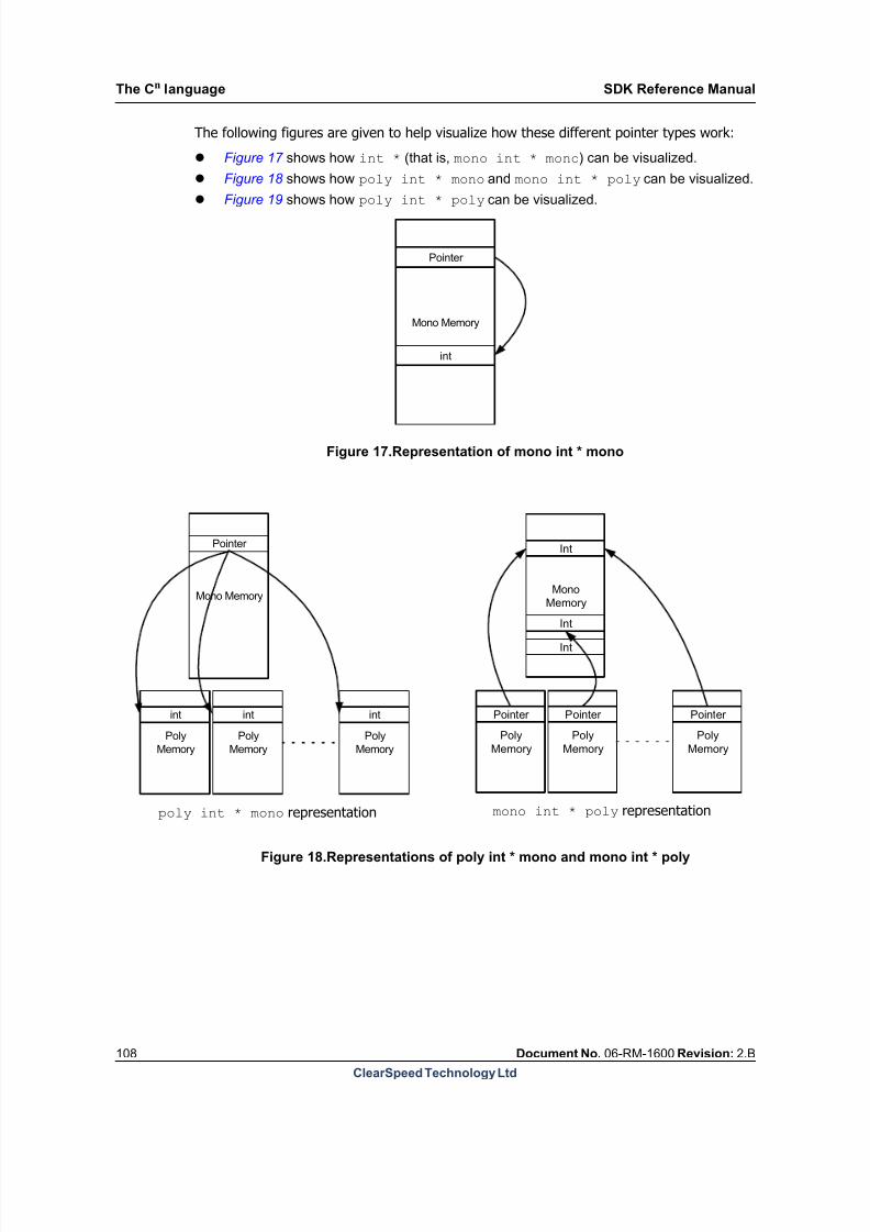
8/9/2019 SDK Reference Manual 3.1 Rev2.B
http://slidepdf.com/reader/full/sdk-reference-manual-31-rev2b 108/204

8/9/2019 SDK Reference Manual 3.1 Rev2.B
http://slidepdf.com/reader/full/sdk-reference-manual-31-rev2b 109/204
Poly
Memory
Poly
Memory
Poly
Memory
Pointer Pointer Pointer
Int
Int
Int
SDK Reference Manual The Cn language
Document No. 06-RM-1600 Revision: 2.B 109
ClearSpeed Technology Ltd
Figure 19.Representation of poly int * poly
Although all these pointer types generally behave as expected, see the comments about de-referencing in Section 11.6: Assignment on page 112 .
More complex pointer types
As with normal C pointers, it is also possible to insert the const specifier on either side of theasterisk resulting in 16 different types of pointers.
Pointer declarations can be chained together, as in C, to give pointers to pointers to objects,and higher order pointers as well. For example:
/* mono pointer to const poly pointer to mono pointer to poly int */poly int * * poly const * foo;
This is displayed graphically in Figure 20 .
Mono
Memory
Poly
Memory
Poly
Memory
Poly
Memory
Pointer
Pointer
Pointer Pointer Pointer
int
int
int
Pointer
Pointer
foo
Stage 1: Mono pointer to const poly pointer (* const poly * foo)
Stage 2: Constant polypointer to mono pointer (* * const poly)
Stage 3: Mono pointer to poly integer ( poly int *)
Stage 4: Poly integer
Figure 20.Representation of poly int * * poly const * foo

8/9/2019 SDK Reference Manual 3.1 Rev2.B
http://slidepdf.com/reader/full/sdk-reference-manual-31-rev2b 110/204
The Cn language SDK Reference Manual
110 Document No. 06-RM-1600 Revision: 2.B
ClearSpeed Technology Ltd
Reading the pointer declaration from right to left, the first pointer is a mono pointer to a constpoly pointer. This is represented in Stage 1.
Stage 1 shows that the mono pointer points to the same location in poly memory on
each PE.
Stage 2 shows the const poly pointer to a mono pointer. Each pointer in poly memory
can potentially point to a different location in mono space.
Stage 3 shows the mono pointer pointed to in stage 2 pointing back into poly memory,
but this time, as the mono pointer can be different for each PE, it can point to different
locations in poly memory.
Stage 4, finally, is the actual value being pointed to in poly memory.
11.5.3 Array types
The syntax for declaring an array in Cn is similar to the syntax in C. It is possible to use themultiplicity specifier in an array declaration. Consider the following:
poly int array[60];
The poly specifier only applies to the base type of the array (the type of the elements of thearray). This example will reserve a space in each instance of poly memory for 60 ints, theaddress of this memory will be at the same location in each PE. By looking at Figure 18 youcan see that the array is in effect a poly int * mono. It is not possible to create a polyint * poly using array notation.
Multi-dimensional arrays are supported in Cn in exactly the same way as for ANSI C.
There are some additional restrictions when dealing with arrays, specifically array subscript-ing (see Section 11.6 ).
11.5.4 Struct and union typesThis section applies to both structs and unions. Wherever a struct is described, a union canbe substituted.
The C language distinguishes between the declaration and definition of objects. A declara- tion is where an object type is specified but no object of that type is created, for example, astruct declaration. A definition is where an object of a particular type is created, that is,memory is actually reserved for the object, for example, a variable definition.
Structs and unions match their C equivalents, the only difference being the type of objectsone can declare inside a struct declaration.
Multiplicity within structs
Standard C allows any variable declaration that is valid outside a struct declaration to appearinside it, with the exception of storage class specifiers. Cn has the additional restriction thatmultiplicity specifiers cannot be included for objects created inside the struct. The reason forthis is that the struct, at the point of declaration is not actually allocated space in memory:it is not until an object of that struct is created that memory is allocated. Therefore declaringa poly definition inside a struct, then defining an instance of that struct in the mono domainwill result in contradictory multiplicity specifications.

8/9/2019 SDK Reference Manual 3.1 Rev2.B
http://slidepdf.com/reader/full/sdk-reference-manual-31-rev2b 111/204
SDK Reference Manual The Cn language
Document No. 06-RM-1600 Revision: 2.B 111
ClearSpeed Technology Ltd
For example, the following declarations and definitions are legal:
struct _A { /* define a struct */ int a; char b;
float c;};
poly struct _A foo; /* define foo to be poly struct_A */
The struct declaration just declares the contents of the struct, not where that memoryresides. At the time of object definition, the compiler resolves where memory should be allo-cated for the object.
It should be clear from this explanation that the following code is invalid :
struct _B { /* define a struct */ poly int a; /* illegal use of multiplicity */ mono char b; /* illegal use of multiplicity */ poly float c; /* illegal use of multiplicity */
};
poly struct _B bar; /* in which domain should bar.b exist? */mono struct _B bing; /* where would bing.a and bing.c get created? */
Multiplicity of pointers
Only the object being declared inside a struct is prohibited from having a multiplicity specifier.When pointers were described, it was suggested that you think of pointers as two parts: onethe pointer being created, the other the base type of the pointer. Multiplicity can thereforebe used on the base type of pointers, but not on the pointer itself. It can be seen that if nomultiplicity specifiers were allowed anywhere inside a struct or union, it would be impossibleto declare a pointer to poly data inside a struct. In the following example, all declarations are
legal Cn:
union _C { /* define a union */ poly int * a; mono int * poly * b;};
poly union _C fred;mono union _C barney;
In the declaration of fred, the identifier a is declared as a poly pointer to a poly int (polyint * poly) and b is declared as a poly pointer to a poly pointer to a mono int (mono int* poly * poly).
In the declaration of barney, a is declared as a mono pointer to a poly int (poly int *mono) and b is declared as a mono pointer to a poly pointer to a mono int ( mono int *poly * mono).
Multiplicity of arrays versus pointers
In the case of an array definition inside a struct or union, the base type of the array cannotcarry a multiplicity specifier. The multiplicity specified for an object of the struct or union typedefines the multiplicity of the fields. This is one instance where arrays and pointers are notinterchangeable.

8/9/2019 SDK Reference Manual 3.1 Rev2.B
http://slidepdf.com/reader/full/sdk-reference-manual-31-rev2b 112/204

8/9/2019 SDK Reference Manual 3.1 Rev2.B
http://slidepdf.com/reader/full/sdk-reference-manual-31-rev2b 113/204
SDK Reference Manual The Cn language
Document No. 06-RM-1600 Revision: 2.B 113
ClearSpeed Technology Ltd
A mono value can also be assigned to a poly variable. In this case the same value is copiedto every instance of the variable on each PE, for example:
mono int x;poly int px;
px = x;
After this operation, every PE’s px will contain the value of the mono variable x.
However, it is not obvious what should happen when assigning a poly to a mono – that iswhen taking data from the multiple instances of the poly variable and storing it in the singlemono variable. Therefore direct assignment from the poly domain to mono is not allowed inCn.
There are however, many instances when it is useful to transfer data from poly memory tomono space and so the standard Cn libraries contain a well defined suite of functions for datatransfer between mono and poly memory.
The standard Cn
libraries also include reduction operations which allow multiple values froma poly variable to be combined, in various ways, into a single mono value.
11.6.1 Pointer dereferencing
Note that certain Cn statements, if they were to be allowed, would require an implicit poly tomono assignment. The compiler does not currently support such implicit transfers, for effi-ciency reasons. One such operation is de-referencing a mono char * poly pointer (seeFigure 18 ). Attempting to dereference such a pointer will result in a poly object, but the datais stored in the mono domain and would therefore need to be copied to poly space.
This also relates to arrays because it would seem possible to create a conventional, mono,array, then attempt to access it using a poly variable as the index. This may seem a useful
feature but, again, because it implicitly dereferences a mono * poly pointer it is notallowed.
The compiler will report any attempt to dereference a mono * poly pointer as an error.The desired result can be achieved using the standard libraries.
11.7 Expressions
Cn supports all the same operators as C. However, some expressions have slightly differentbehavior depending on the multiplicity of their operands. For details of the operators in Cn,see Section 11.16 .
Mono and poly variables can usually be used interchangeably in expressions. The only diffi-culty is expressions that result in an assignment (see Section 11.6 ). It is perfectly valid toadd a poly and a mono, to subtract them, or to perform any other operation. However, theresult of any expression containing a poly and a mono object is invariably poly, and a polyobject can only be assigned to another poly object.
8/9/2019 SDK Reference Manual 3.1 Rev2.B
http://slidepdf.com/reader/full/sdk-reference-manual-31-rev2b 114/204
The Cn language SDK Reference Manual
114 Document No. 06-RM-1600 Revision: 2.B
ClearSpeed Technology Ltd
Therefore, an expression can mix mono and poly variables as long as the expression doesnot result in a poly value being assigned to a mono value. Mono values will be promoted topoly in mixed expressions. For example:
poly int x;
int y;x = x + y;
In the above expression, y will be promoted to a poly type before being added to (everyinstance of) x.
The conditional operator, ?:, behaves similarly to an if...else statement and thereforeconforms to the same rules with respect to execution of mono or poly expressions inside amono or poly conditional, see Section 11.8.2 .
11.7.1 Casting
Note: when casting a poly variable to another type, the cast must include the poly specifier.
For example:poly int k;poly float value;
k=2;value=(poly float) k;
11.8 Flow Control
The Cn language supports the same basic flow control statements as ANSI C with some minoradditions. The basic flow control constructs are:
if statement
if...else statement
for loop
while loop
do...while loop
switch statements
goto
Each of these flow control statements uses expressions for loop or branch control. The com-plication in Cn is that these expressions can be of mono or poly domain.
The important point here is that there is a single instruction stream to be executed by all
(mono and poly) processing elements. This means that mono and poly conditional constructsbehave differently:
A mono expression for the condition affects all mono and poly processing elements
and so it is handled in the normal way, that is, by using jumps around code which is not
executed (or which is executed multiple times).
A poly condition only affects the poly execution unit and, importantly, on some of the
PEs the expression may be true and false on others. This has two implications: firstly
mono statements are executed regardless of the result of the poly condition. Secondly,
the PEs require a mechanism to allow some of them to skip certain instructions – this is
the enable state described below.
8/9/2019 SDK Reference Manual 3.1 Rev2.B
http://slidepdf.com/reader/full/sdk-reference-manual-31-rev2b 115/204
SDK Reference Manual The Cn language
Document No. 06-RM-1600 Revision: 2.B 115
ClearSpeed Technology Ltd
Note: A mono condition is an expression containing only mono variables. If any componentof the conditional expression is poly, then the whole expression is poly.
Additional statements that implement flow control are:
break statements
continue statements
return statements
11.8.1 Poly flow control
Each PE contains an enable state . This tells the PE whether it is “switched on” or not (whetherit should execute instructions or not). For example, you may wish to only perform processingon PEs with an even PE number. The following piece of Cn code would perform this opera-tion:
poly int penum = get_penum(); /* use Cn standard library function */if (penum % 2 == 0)
{ // do some processing here}
The descriptions of the if and if...else statements are used below in order to explainpoly flow control in detail. The principles also apply to loop constructs.
11.8.2 If statements
if statements in Cn have the same form as ANSI C. The format is repeated here for clarity:
if (expression) {statement-list}
As described above, expression can be mono or poly.
Mono if
A mono if statement is exactly the same as a conventional ANSI C if statement.
In the mono if statement, if expression is false, statement-list will be skipped entirely andexecution will continue after the if statement.
Poly if
In the case of a poly if, expression can be true on some PEs and false on others. This iswhere the PE enable state comes in: all the PEs for which the condition is false are disabledfor the duration of the if statement. The statement-list will then be executed, but any polystatements will only have an effect on the PEs that are enabled. Even if all PEs are switched
off by expression , the statement-list will still get executed, but all poly statements will donothing. This has the side effect that all mono statements inside a poly conditional will getexecuted irrespective of the expression controlling the if. Effectively, a poly condition isinvisible to any mono code inside that if statement.

8/9/2019 SDK Reference Manual 3.1 Rev2.B
http://slidepdf.com/reader/full/sdk-reference-manual-31-rev2b 116/204
The Cn language SDK Reference Manual
116 Document No. 06-RM-1600 Revision: 2.B
ClearSpeed Technology Ltd
For example:
poly int penum = get_penum();poly int foo = 0;mono int bar;
if (penum % 2) { // all odd numbered PEs foo = penum * 10; bar = 1;}
At the end of the above code fragment, foo will contain the value 0 on all even PEs and bethe PE number times ten on all odd numbered PEs, bar will be 1. It may be worth notingthat, although the condition is invisible to the mono statements, they are still within a com-pound statement block (with all the implications for variable scope that this implies).
The following example may help to stress the point about mono statements in a poly if.
poly int foo = 0;mono int bar = 0;
if (foo) { bar = 1;}
Note: Note that bar will have the value 1 at the end of this code, even though every singlePE was disabled for the if statement. As described above, the mono statements will executeirrespective of any poly conditionals.
if statements can be nested just as in C. Nested poly if statements behave as would beexpected: poly statements are only executed on PEs where all the nested conditional expres-sions evaluated to true.
If...else statements
The if...else statement in Cn is similar to the ANSI C version. The format is repeatedhere for clarity.
if (expression) {if-statement-list} else {else-statement-list}
A poly if...else works by enabling all the PEs that match the conditional expression, anddisabling all the others. For the else clause, the enable state of all the PEs is inverted: thosePEs that were enabled by the condition are disabled and vice-versa. Note that any PEs whichwere disabled before the if will still be disabled for the else-statement-list.
if...else statements follow the same rules as if statements with respect to poly andmono conditionals. The only thing to note here is that an if...else statement with a polycondition will be executed with some PEs enabled for the if-statement-list and the
remainder enabled for the else-statement-list. However, all mono statements insideboth the if part and the else part of the statement will get executed, regardless of thecondition.
8/9/2019 SDK Reference Manual 3.1 Rev2.B
http://slidepdf.com/reader/full/sdk-reference-manual-31-rev2b 117/204
SDK Reference Manual The Cn language
Document No. 06-RM-1600 Revision: 2.B 117
ClearSpeed Technology Ltd
For example:
poly int penum = get_penum();mono int foo, bar;
if (penum % 2) { // executed on all odd PEs foo = 1;} else { // executed on all even PEs foo = 2; bar = 2;}
At the end of this code fragment, both foo and bar will be set to 2 (foo will initially havebeen set to 1 and then this is overwritten by the second assignment). Even if the secondbranch had all PEs disabled, all the mono statements would still get executed.

8/9/2019 SDK Reference Manual 3.1 Rev2.B
http://slidepdf.com/reader/full/sdk-reference-manual-31-rev2b 118/204
8/9/2019 SDK Reference Manual 3.1 Rev2.B
http://slidepdf.com/reader/full/sdk-reference-manual-31-rev2b 119/204
SDK Reference Manual The Cn language
Document No. 06-RM-1600 Revision: 2.B 119
ClearSpeed Technology Ltd
A pragma can be used before a switch statement to force the compiler to generate a jumptable. This may improve performance in some cases. See Section 11.10.3: Generating jumptables for switch statements on page 125 .
11.8.4 For, while and do...while loopsDue to the similarity of these constructs, the main points will be described together.
A loop with a poly control expression (a poly loop ) will execute as long as the condition istrue on any PE. In other words, the loop will terminate when the loop condition is false onevery PE. Before the loop terminates, any PEs that evaluate the condition as false will be dis-abled for all the remaining iterations. These PEs will no longer participate in the remainderof the loop. When all PEs have evaluated the expression as false, the loop will be terminated.
Analogously to if statements, mono statements inside the loop will get executed on everyiteration. Unlike if statements, if all PEs are disabled after evaluating the condition, the loopwill terminate immediately so even the mono statements will not be executed. In other
words, a poly loop can iterate zero times.Consider the following piece of code:
poly int i;mono int max_loop_count = 0;poly int this_loop_count = 0;
... /* i is set in this code, value may be different on every PE */while (i > 0) { i--; /* Decrement poly loop control */ max_loop_count++; /* Increment mono loop_count: every time */ this_loop_count++; /* Increment poly loop_count: only while i >0 */}
At the end of this code, each PE will have a different value of this_loop_count, reflectingthe number of iterations on that PE (the initial value of i). The value of max_loop_count will depend on the largest value of i across all PEs. In this case, max_loop_count may bea useful value since it informs you the total number of iterations the loop went through.
Break and continue
break and continue are used with loops to control the flow of the program.
An alternative to goto
goto statements can sometimes be useful in ANSI C, for example to handle errors in deeplynested loops. Similar behavior can be achieved in Cn as the break and continue state-
ments have been extended to allow their use with labels. In Cn
, label declarations areallowed only before keywords which start a loop construct (for, while and do). The break and continue statements in Cn can specify an optional label. This allows the program to

8/9/2019 SDK Reference Manual 3.1 Rev2.B
http://slidepdf.com/reader/full/sdk-reference-manual-31-rev2b 120/204
The Cn language SDK Reference Manual
120 Document No. 06-RM-1600 Revision: 2.B
ClearSpeed Technology Ltd
break out of heavily nested loops. For instance, consider this example (for simplicity, assumeall variables are mono):
L1: for (i = 0; i < 10000; i++) {L2: while(j > 100) { /* execution continues here after
continue L2 */L3: do { ... if (foo == 0) { break L1; } ... if (bar == 0) { continue L2; } ... } while (a != b); } }
/* execution continues here after break L1 */
In the above example, the statement break L1 will break out of the outermost for loop,meaning execution will continue after the first for loop. The continue L2 statement willcause the next iteration of the while loop to be executed. This gives nearly all of the flexi-bility of goto, but in a more structured way.
The break and continue statements are part of the loop control, just as much as the loopcondition is. They are therefore treated as either mono or poly statements depending on thedomain of the loop condition. Their precise behavior therefore varies depending on whetherthe loop condition is a mono or poly expression. With a labelled break or continue, thedomain of the statement is determined by the loop it is controlling rather than the innermostloop it is within.
GotoGoto statements can sometimes be useful and Cn allows for the use of goto in all contextsother than when the branch would cross a poly condition level boundary. For instance, con-sider the following example:

8/9/2019 SDK Reference Manual 3.1 Rev2.B
http://slidepdf.com/reader/full/sdk-reference-manual-31-rev2b 121/204
SDK Reference Manual The Cn language
Document No. 06-RM-1600 Revision: 2.B 121
ClearSpeed Technology Ltd
#include <stdio.h>
int main(void)
{ poly int x = 10;
printf("A\n");labelA: if (x) { goto labelD; printf("poly if\n");labelD: printf("D\n"); }
printf("B\n"); goto labelC;labelB:
printf("C\n");labelC:
return 0;}
The above example prints the output:
ADB
Changing the line goto labelD; to goto labelB; is not allowed as the branch wouldthen cross a poly condition level boundary, expressed by the poly if.
Mono loopsThe behavior of mono break and continue statements is exactly as in standard C: thecode will exit the loop at the break statement and no further code inside the loop will beexecuted. The continue statement causes the next iteration of the loop to begin immedi-ately.
In a mono loop, break and continue are mono statements. This means that they are exe-cuted even if they are within a poly conditional, for example (see Table 27 ).
For example, consider the following code where i is a mono variable and foo is poly:
for (i = 0; i < 10000; i++) { if (foo == 0) { break; }
...}
This loop will terminate immediately because the mono break is executed unconditionallywithin the poly if.
Poly loops
In a poly loop, the loop control statements are treated as poly statements. They thereforebehave as expected for poly code: the PEs which execute them either stop executing codein the loop (break) or are disabled unto the start of the next loop iteration (continue).
8/9/2019 SDK Reference Manual 3.1 Rev2.B
http://slidepdf.com/reader/full/sdk-reference-manual-31-rev2b 122/204
The Cn language SDK Reference Manual
122 Document No. 06-RM-1600 Revision: 2.B
ClearSpeed Technology Ltd
To understand this behavior remember that PEs cannot execute jumps. The only way to han-dle these statements is to disable the PEs. In the case of break, the PEs are disabled untilthe loop terminates. In this way, the PEs which execute the break will no longer participatein the loop. In the case of continue, the PEs are disabled for the current iteration. In this
way, the PEs which execute the continue will not participate in this iteration but they willre-evaluate the loop condition.
The result of this is that some PEs can stop executing the code in the loop while others con-tinue to iterate. Similarly some PEs can stop executing the current iteration while others con-tinue. This preserves the semantics of break and continue for poly processing.
If all PEs are disabled after the break statement then the loop will terminate at the end ofthe current iteration.
Any PEs which do not execute the break or continue will carry on executing the loop code.Similarly, any mono code in the loop, after the break orcontinue, will always be executedat least once.
The following sections describe the behavior of poly break and continue in more detail.
Poly break
A poly break works by immediately disabling all PEs which execute it. Any other PEs (andany mono code) execute until the end of the current iteration. If, at this point, all PEs aredisabled then the loop will terminate, otherwise the enabled PEs will continue to iterate untilall are disabled (either by the loop condition or a break).
Consider first, the simple example below where foo is a poly variable:
while (foo < 100) { if (bar == 0) { break;
}... mono code ... poly code}
In this case, the break statement will disable all PEs that execute it (if bar is a mono expres-sion then this will be all PEs). Note that some PEs may already be disabled, either becausethey have reached the loop termination condition or because they have previously executedthe break.
The processor continues executing the code after the break. The following poly statementswill not be executed by the PEs which are disabled. Any following mono statements will beexecuted.
When the processor gets to the end of the iteration, the loop condition is evaluated and theenable state of the PEs is checked. If all PEs are disabled, iteration of the loop will be termi-nated. This means that if all PEs execute the break, the following mono code will be exe-cuted once before the loop exits.
With a labelled break, the domain of the statement is determined by the loop it is control-ling. Otherwise, the same principle applies: each loop being exited ‘unwinds’ as describedabove.
Consider the following example where i, j, a and b are all poly variables:
8/9/2019 SDK Reference Manual 3.1 Rev2.B
http://slidepdf.com/reader/full/sdk-reference-manual-31-rev2b 123/204
SDK Reference Manual The Cn language
Document No. 06-RM-1600 Revision: 2.B 123
ClearSpeed Technology Ltd
L1: for (i = 0; i < 10000; i++) {L2: while(j > 100) {L3: do {
... if (foo == bar) { break L2; } ... L3 mono code ... L3 poly code } while (a != b); ... L2 mono code ... L2 poly code } // execution continues here for PEs that execute break L2 ... }
In this case, the code indicated as “L3 poly code” and “L2 poly code” will be ignored
by PEs that execute the break L2 statement and the code marked as “L3 mono code”and “L2 mono code” will be executed.
Poly continue
A poly continue works by immediately disabling all PEs which execute it for the remainderof the current iteration only . The current loop iteration then runs to completion. Any PEswhich were disabled by the continue will be re-enabled and then the loop condition will bere-evaluated.
The effect of this is that the PEs which execute the continue will cease to execute code inthe loop until the loop condition is re-evaluated. The other PEs will execute the whole of theremainder of the code in the loop. As before, any mono code in the loop will be executed
unconditionally.Consider the example below where foo is a poly variable:
while (foo < 100) { if (bar == 0) { continue; }
... mono code ... poly code}
In this case, the continue statement will disable all PEs that execute it – if bar is a monoexpression then this will be all PEs. Note that some PEs may already be disabled becausethey have reached the loop termination condition.
The processor continues executing the code after the continue. The following poly state-ments will not be executed by the PEs which are disabled. Any following mono statementswill be executed.
When the processor gets to the end of the loop, those PEs which were disabled by the con-tinue will be re-enabled. The loop condition is then evaluated and the loop execution contin-ues.
8/9/2019 SDK Reference Manual 3.1 Rev2.B
http://slidepdf.com/reader/full/sdk-reference-manual-31-rev2b 124/204
The Cn language SDK Reference Manual
124 Document No. 06-RM-1600 Revision: 2.B
ClearSpeed Technology Ltd
11.9 Functions
Functions are fundamentally the same in Cn as they are in ANSI C.
11.9.1 Function multiplicityMultiplicity specifiers can be used to specify the return type of a function as well as the typesof any arguments. Return types of functions can be of mono or poly domain. The void returntype can also be either mono or poly. The domain of the function is defined by the returntype.
11.9.2 Returning from functions
As with ANSI C, a function which specifies a return type other than void must have a returnstatement somewhere in the function. It should have one per control flow branch throughthe function.
Mono functions
A return in a mono function behaves exactly as expected: the function returns control to thecalling code at that point.
Poly functions
A return statement in a poly function works by disabling the PEs. Note that the function doesnot actually return control to the calling code until the end of the function body is reached(because program control flow is a mono operation). This means that any mono code afterthe return statement will be executed.
A conditional return will disable those PEs which execute it. These PEs will remain disabled
until the end of the function. Other PEs will execute the rest of the code in the function. Whenthe function returns, all PEs have their enable state restored to what it was on entry.
Consider the following example:
poly int bar(poly int p1, p2) { if (p1) { if (p2) { return -1; // disable appropriate PEs and save the returnvalue of -1 } else { return 0; // disable appropriate PEs and save the returnvalue of 0 } }
... (1) return 0; // PEs which are still enabled save 0 as a return valueand are disabled ... (2)} /* return saved poly values here */
In this case, all PEs for which the condition p1 is true will return a value (either 0 or -1,depending on p2). These PEs will be disabled until the end of the function. All other PEs willcontinue to execute the rest of the poly code in the function. Therefore, poly code at (1) inthis function will be executed by those PEs which have not already specified a return valueof 1 or -1. This is followed by an unconditional return so any poly code at (2) will not beexecuted. All mono code in the function will always be executed.

8/9/2019 SDK Reference Manual 3.1 Rev2.B
http://slidepdf.com/reader/full/sdk-reference-manual-31-rev2b 125/204
SDK Reference Manual The Cn language
Document No. 06-RM-1600 Revision: 2.B 125
ClearSpeed Technology Ltd
11.10 Pragmas
The section outlines the currently supported set of CSX specific pragmas.
11.10.1 Including assembler macros in Cn
The CSX processor instruction set is split between actual instructions and macros providedas part of the SDK in assembler header files. As with C-style macros, these instructions can-not be accessed without first including the correct header in the assembler source. If theseinstructions are to be accessed from assembly functions within Cn code (see Section 11.11:Inline assembler on page 128 ) the header must be included.
To include a particular assembly header in a piece of Cn source code, the assembly includepragma must be used:
#pragma asm_inc <file.inc>
or
#pragma asm_inc “file.inc”
11.10.2 Forcing the alignment of identifiers
The CSX ABI, described in Section Section 13.3: Data representation and allocation on page 158 , defines the alignment of data objects for the CSX processor. The compiler will pro-duce data aligned to these requirements by default. However, it is sometimes useful to beable to override these default settings. The alignment pragma is used to do this for a specificvariable:
#pragma align integer
The scope of the align pragma is the variable declaration which immediately follows it. Theinteger parameter defines the alignment in bytes for the variable. This value can beexpressed in decimal or hexadecimal using the normal C notation.
The following example forces the variable i to be allocated in poly memory at an addresswhich is a multiple of 32 bytes. The pragma has no effect on the alignment of j.
#pragma align 0x20poly int i[200];int j[100];
Note: The Cn pragma for specifying the alignment of variables (#pragma align) can onlybe used with static (global) variables. Specifying this pragma before a local variable allocatedon the stack will have no effect.
11.10.3 Generating jump tables for switch statements
The compiler normally treats switch statements (Section 11.8.3: Switch statements on page 118 ) as a series of conditional branch statements. In some cases, depending on thesize of the switch statement and the nature of the cases, it may be more efficient to generatea jump table.
8/9/2019 SDK Reference Manual 3.1 Rev2.B
http://slidepdf.com/reader/full/sdk-reference-manual-31-rev2b 126/204
The Cn language SDK Reference Manual
126 Document No. 06-RM-1600 Revision: 2.B
ClearSpeed Technology Ltd
The switch pragma can be used to do this for an individual switch statement:
#pragma switch jumptableswitch(program[pc]){
The compiled code can then be checked for changes in code size and speed.
The pragma should appear immediately before the switch statement which is to be translatedas a jump table.
11.10.4 Unrolling loops
There are a number of pragmas available which can be used to influence the behavior of theloop unroller. Each of these pragmas should be placed immediately before the loop to beaffected.
#pragma loop no unroll
This can be used to prevent the loop from being unrolled.#pragma loop unroll(nr )
This can be used to request a loop to be unrolled a certain number of times. The parameternr should be a positive integral value. See also Section 4.4.34: Loop unrolling on page 51 .
#pragma loop maxunroll(nr )
This pragma sets a limit on the number of times the loop will be unrolled. Set immediatelybefore the loop you want to affect. The parameter nr should be a positive integral value indi-cating the maximum unroll factor for the following loop.
11.10.5 Moving code to on-chip memory
It is often important to run performance-critical code from the fast on-chip SRAM rather thanexternal DRAM. While it is possible to have the linker place all code in on-chip memory thisis not always practical due to space limitations. You may want to specify particular, perfor-mance-critical functions to be placed in on-chip memory. The hot pragma provides a tool forachieving this. This pragma takes a bracketed list of function names, all of which must bedefined in the current compilation unit:
#pragma hot (f1, ..., fn)
The scope of the hot pragma is the current compilation unit. Each function in the list will beplaced in on-chip memory by the linker while all other functions will be placed in DRAM.

8/9/2019 SDK Reference Manual 3.1 Rev2.B
http://slidepdf.com/reader/full/sdk-reference-manual-31-rev2b 127/204
SDK Reference Manual The Cn language
Document No. 06-RM-1600 Revision: 2.B 127
ClearSpeed Technology Ltd
The following example forces the functions foo and bar to be placed in on-chip memory,but leaves main in DRAM (the default):
#pragma hot (foo,bar)
int bar(void) {... }
int foo(void) { ... }
int main(void){ ...
for (...) foo() + bar();
...
return 0;}
11.10.6 Setting stack sizes
A pragma can be used to set the size of statically allocated stacks for each thread, as follows:
#pragma static_stack(mono|poly, size, thread )
The first argument defines whether a mono or poly stack size is being defined. The secondargument specifies the stack size in bytes. The third argument specifies the thread numberfor which the stack size is being set.
See Section 12.1: Stack allocation on page 150 for more details on the use of dynamic andstatic stacks.
11.10.7 Controlling inlining functions
The following pragmas control inlining function definitions.
#pragma inline
This pragma should be placed immediately before the definition of a procedure. It is arequest for the following function to be inlined, but doesn’t guarantee inlining. The behaviorwhen marking functions for inlining using this pragma is not the same as when the inlinekeyword is used. Using the inline pragma does not affect whether or not a function is gen-erated in its own right. This does mean, however, that you may need to use the static key-word to avoid multiple symbol definitions where an inline function is defined in a header fileand included in multiple source files within a project.
The inline pragma can be used with on/off placed after it, for example:
#pragma inline on
The effect of this is to mark all functions declared after the pragma with an inline pragma,until a #pragma inline off is seen.
#pragma inlinecalls
This pragma can be placed before a function call site to indicate that the called function (orfunctions) within the succeeding statement should be inlined. This pragma can also beturned ‘on’ or ‘off’ in the same way as the inline pragma.

8/9/2019 SDK Reference Manual 3.1 Rev2.B
http://slidepdf.com/reader/full/sdk-reference-manual-31-rev2b 128/204
The Cn language SDK Reference Manual
128 Document No. 06-RM-1600 Revision: 2.B
ClearSpeed Technology Ltd
#pragma noinline
This pragma can be placed immediately before a function definition and will ensure that thefunction is not inlined, even at –O3 and above when auto-inlining is enabled.
#pragma forceinlineThis pragma is again placed just before a function definition and indicates that the functionwill always be inlined. This overcomes the inlining rules above, except for those rules thataffect functional correctness (varags, recursive functions and computed gotos).
11.11 Inline assembler
Inline assembly code in Cn is defined using a similar syntax to functions and, as such, mustbe named. A consequence of this is that they cannot be defined within basic blocks.
An inline assembly sequence can be defined using the Cn keyword __asm. These keywords
are storage class specifiers and therefore cannot be combined with static or extern. Theprototype of the assembly function can, however, be specified as static or extern, but itcannot use the __asm keyword. The __asm keyword can only be attached to function defi-nitions. A function with storage class __asm must have a function body and cannot consistsolely of a function prototype. Such a function is referred to as an assembly function.
The assembly code starts at the first character after the opening brace of the body of theassembly function and ends with the last character before the matching closing brace.
11.11.1 Enable state
Any changes to the enable state within an assembly function must be completely containedwithin that function. The enable state must be restored to its original state when the assem-
bly function exits. In other words, the enable state when the assembly function exits mustbe the same as it was at the entry to the function.
For example, code such as the following is not allowed (although the compiler does not checkfor this):
__asm void poly_if_on_arg(poly char a){ @[ .poly; ] cmp ${a}, 0 ; if.nzero ;}
The compiler cannot tell that the assembly function has changed the enable state and so itmay perform some incorrect optimizations.
Either perform such conditional code entirely in inline assembly or entirely in Cn, not a mix-ture of both.
11.11.2 Use of variables within assembler code
Parameters to an assembly function and locally-defined variables (variables defined withinthe assembly function) can be referenced in the assembly code using their symbolic names

8/9/2019 SDK Reference Manual 3.1 Rev2.B
http://slidepdf.com/reader/full/sdk-reference-manual-31-rev2b 129/204
SDK Reference Manual The Cn language
Document No. 06-RM-1600 Revision: 2.B 129
ClearSpeed Technology Ltd
with the @{variable} syntax. This allows register allocation to be performed by the com-piler.
A number of operand modifiers are provided to change and constrain the way that operandsare interpreted by both the compiler and, in some cases, the assembler.
The following is a simple example of an assembly function implementing single-precisionfloating-point add. Note the use of @{} to specify the return value of the function.
__asm mono float __addf(mono float x, mono float y){ add @{}f, @{x}f, @{y}f;}
This could be called from the Cn code as follows:
int main(void){ float y = __addf(10.0, 20.0); return (int)y;
}
Byte selection operators
To use only the least significant or most significant bytes of an operand, the .lsbytes and.msbytes operators are provided. The format of these is as follows:
.lsbytes ( variable_name, number_of_bytes );
.msbytes ( variable_name, number_of_bytes );
Any number of bytes can be specified. If the number of bytes specified is greater than thesize of the operand, the operator is ignored. An example of using these is shown below:
__asm mono char __add(mono char x, mono int y){
add @{}, @{x}, .lsbytes(@{y}, 2);}
The .lsbytes operator in this example is used to extract the least significant byte of y inorder to add it to x, a 2-byte value (as registers on in mono are a minimum of 2 bytes insize). The actual byte that gets chosen is dependant upon the endianness of the target plat-form. For a wider discussion on these and other assembly directives along with more detailedexamples, see Chapter 14: Assembly language .
11.11.3 Specifying constraints on register use
The compiler manages register allocation for variables used in inline assembly. To allow thecompiler to do this correctly, you must ensure you fully specify the usage of registers and
memory. Failure to do this may cause hard-to-track-down problems. In many cases, thesewill not cause compilation warnings or errors, which makes them particularly troublesome.
The use of registers, and other restrictions, are specified by a set of constraint directives(Section 11.11.4: Constraint directives on page 131 ).
There are some registers which can be written to without any additional constraints beingspecified:
the result register (@{})
scratch registers (defined with the .scratch directive)

8/9/2019 SDK Reference Manual 3.1 Rev2.B
http://slidepdf.com/reader/full/sdk-reference-manual-31-rev2b 130/204
The Cn language SDK Reference Manual
130 Document No. 06-RM-1600 Revision: 2.B
ClearSpeed Technology Ltd
There are some restrictions on these registers, as described below. If you unsure of the rules,then it is better to specify a .interfere directive to be safe.
Writing to the result register
If any part of the result register is written before a read or write of another register, then itis necessary to add an explicit interference clause to the inline assembly code. This is becausethe compiler assumes that the result register is written after all other registers. If this is notthe case then the compiler may incorrectly allocate the result register.
For example:
int __asm invalid1(int x, int y){
add @{}, @{x}, @{x};add @{}, @{}, @{y};
}
This example is incorrect because the register allocator may decide that the optimal alloca-
tion is to assign the result register and y to the same register, which would cause the firstadd instruction to overwrite argument y and make the second add use the wrong value.
This is fixed in the following way:
int __asm valid1(int x, int y){
@[.interfere (x,) (y,)
]add @{}, @{x}, @{x} ;add @{}, @{}, @{y} ;
}
Note: The result register is specified by a blank in the interference pair.
The same rule applies to interference between scratch registers and the result register.Scratch registers automatically interfere with each other and argument registers, but not withthe result register, so any writes to the result register before reading or writing a scratch reg-ister will require a directive to specify interference between the result and scratch registers.
Writing to argument registers
To write to argument registers, a .clobber directive is required to inform the compiler thatthose registers are written to.
For example, this code modifies the argument y:
int __asm invalid2(int x, int y)
{ add @{y}, @{y}, @{x};add @{}, @{y}, @{x};
}

8/9/2019 SDK Reference Manual 3.1 Rev2.B
http://slidepdf.com/reader/full/sdk-reference-manual-31-rev2b 131/204
SDK Reference Manual The Cn language
Document No. 06-RM-1600 Revision: 2.B 131
ClearSpeed Technology Ltd
This should include a .clobber directive as shown:
int __asm valid2(int x, int y){
@[
.clobber y.interfere (x, y)]add @{y}, @{y}, @{x};add @{}, @{y}, @{x};
}
The additional .interfere directive is also required because in this case we are expectingto be able to read the value of x after y is written in the first add instruction, so they cannotbe stored in the same register.
Writing to other registers
When writing to other registers, you must add a .write directive to show that you are writ-ing a register which is not otherwise specified as an argument (.clobber should be usedhere), the result or a scratch. For example:
.write 8:m2;
Using .nobarrier
For some inline assembly sections (those which do not use swazzle or vector operations), itis possible to specify the .nobarrier directive to allow the scheduler more freedom in mov-ing items past the inline assembly block.
When this is used, you must specify whether the inline assembly section reads or writesmemory (.read .memory or .write .memory), as well as the other register-relateddirectives. This allows the scheduler to have enough information about the content of the
inline assembly block to ensure correct scheduling around it.
11.11.4 Constraint directives
Constraints on the use of variables and other properties of the assembly function can bedefined using the @[constraints] directive. Multiple constraints can be listed, one perline, within the brackets.
.scratch name [, name]*
This is followed by a list of names separated by commas. This directive declares new objectsof type scratch that can be used in the assembly code, in other words the directive simplyintroduces new symbols that can be referenced with the assembler body. Applying additionalconstraints, as given below, allows scratch symbols to be used as symbolic references to par-ticular classes of registers, and so on. The following example defines symbols y and x to bescratch:
@[.scratch x, y
]
It is possible for the compiler to allocate scratch registers (declared using .scratch) to thesame registers that are used as return registers (denoted @{} in the assembly code). If anypart of the return register is written before a read of a scratch or operand register, you shoulddeclare an explicit interference (see Section 11.11.3: Specifying constraints on register useon page 129 ). This avoids the scratch or operand register being overlapped with the return

8/9/2019 SDK Reference Manual 3.1 Rev2.B
http://slidepdf.com/reader/full/sdk-reference-manual-31-rev2b 132/204
The Cn language SDK Reference Manual
132 Document No. 06-RM-1600 Revision: 2.B
ClearSpeed Technology Ltd
register. Scratch registers automatically interfere with one another so it is not necessary tospecify them in an interfere directive.
.restrict [variable:register_class]*
This directive is followed by a list of register restrictions (possibly empty) separated by com-mas. This directive allows you to restrict a symbol to a register class. For example, if the sym-bol piX is a 4-byte poly value, its use should be restricted to the poly registers 0:p4, 4:p4 and so on, the pdreg class. A register restriction consists of a variable followed by a colonfollowed by a register class.
The set of register classes are defined as follows:
mwreg, mdreg and mddreg are 2, 4, and 8-byte mono registers, respectively
preg, pwreg, pdreg and pddreg are 1, 2, 4, and 8-byte poly registers, respectively
pfvecreg and pdvecreg are 4x4-byte and 4x8-byte poly vector registers,
respectively, and
p2fvecreg and p2dvecreg are 2x4-byte and 2x8-byte poly vector registers,
respectively
For example, consider the following assembler function which, given a mono unsigned shortas an argument, adds the constant value 0x1000 and returns the result. The restrict directive is used to constrain the temporary register used to hold the constant 0x1000 to a2-byte mono register mwreg, as follows:
__asm mono unsigned short__add1000(mono unsigned short x){ @[ .scratch temp .restrict temp:mwreg ]
mov @{temp}, 0x1000;
add @{}, @{x}, @{temp};}
Optionally, an explicit restriction can be added. This requests the compiler to allocate therestricted variable to a particular set of registers within the specified register class. Such anexplicit restriction consists of a list of registers separated by commas and surrounded byangle brackets. In the above example, rather than just restricting temp to the register classmwreg , it could be allocated to the mono return register (8:m2) by using the expression:
.restrict temp:mwreg <8:m2>
The full set of registers for each register type is defined in Table 28 .
0:m2, 2:m2 ... 62:m2 the set of 2-byte mono registers
0:m4, 4:m4, ... 60:m4 the set of 4-byte mono registers
0:m8, 8:m8, ... 56:m8 the set of 8-byte mono registers
0:p1, 1:p1, ... 127:p1 the set of 1-byte poly registers
0:p2, 2:p2, ... 126:p2 the set of 2-byte poly registers
0:p4, 4:p4, ... 124:p4 the set of 4-byte poly registers
0:p8, 8:p8, ... 120p8 the set of 8-byte poly registers
Table 28. Register range definitions
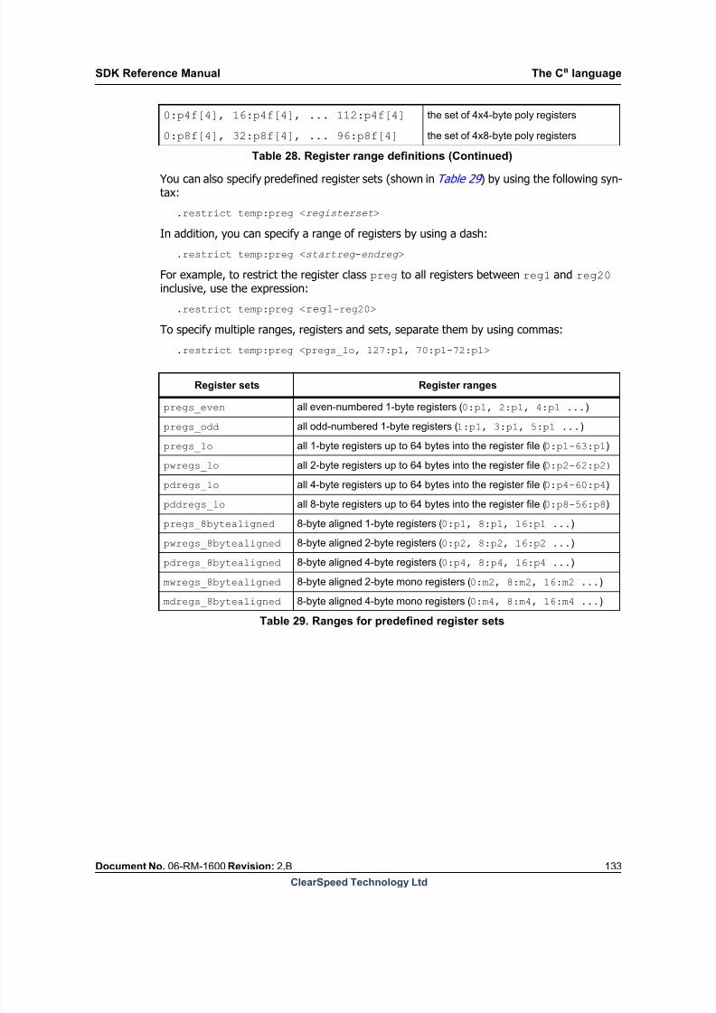
8/9/2019 SDK Reference Manual 3.1 Rev2.B
http://slidepdf.com/reader/full/sdk-reference-manual-31-rev2b 133/204
SDK Reference Manual The Cn language
Document No. 06-RM-1600 Revision: 2.B 133
ClearSpeed Technology Ltd
You can also specify predefined register sets (shown in Table 29 ) by using the following syn-tax:
.restrict temp:preg <registerset>
In addition, you can specify a range of registers by using a dash:
.restrict temp:preg <startreg -endreg >
For example, to restrict the register class preg to all registers between reg1 and reg20 inclusive, use the expression:
.restrict temp:preg <reg1-reg20>
To specify multiple ranges, registers and sets, separate them by using commas:
.restrict temp:preg <pregs_lo, 127:p1, 70:p1-72:p1>
0:p4f[4], 16:p4f[4], ... 112:p4f[4] the set of 4x4-byte poly registers
0:p8f[4], 32:p8f[4], ... 96:p8f[4] the set of 4x8-byte poly registers
Register sets Register ranges
pregs_even all even-numbered 1-byte registers (0:p1, 2:p1, 4:p1 ...)
pregs_odd all odd-numbered 1-byte registers (1:p1, 3:p1, 5:p1 ...)
pregs_lo all 1-byte registers up to 64 bytes into the register file (0:p1-63:p1)
pwregs_lo all 2-byte registers up to 64 bytes into the register file (0:p2-62:p2)
pdregs_lo all 4-byte registers up to 64 bytes into the register file (0:p4-60:p4)
pddregs_lo all 8-byte registers up to 64 bytes into the register file (0:p8-56:p8)pregs_8bytealigned 8-byte aligned 1-byte registers (0:p1, 8:p1, 16:p1 ...)
pwregs_8bytealigned 8-byte aligned 2-byte registers (0:p2, 8:p2, 16:p2 ...)
pdregs_8bytealigned 8-byte aligned 4-byte registers (0:p4, 8:p4, 16:p4 ...)
mwregs_8bytealigned 8-byte aligned 2-byte mono registers (0:m2, 8:m2, 16:m2 ...)
mdregs_8bytealigned 8-byte aligned 4-byte mono registers (0:m4, 8:m4, 16:m4 ...)
Table 29. Ranges for predefined register sets
Table 28. Register range definitions (Continued)
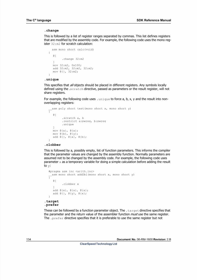
8/9/2019 SDK Reference Manual 3.1 Rev2.B
http://slidepdf.com/reader/full/sdk-reference-manual-31-rev2b 134/204
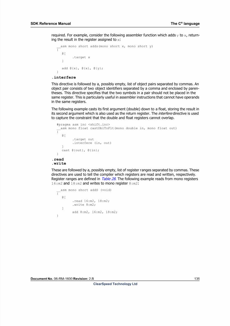
8/9/2019 SDK Reference Manual 3.1 Rev2.B
http://slidepdf.com/reader/full/sdk-reference-manual-31-rev2b 135/204
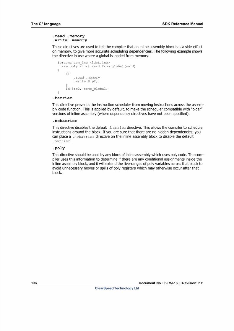
8/9/2019 SDK Reference Manual 3.1 Rev2.B
http://slidepdf.com/reader/full/sdk-reference-manual-31-rev2b 136/204
The Cn language SDK Reference Manual
136 Document No. 06-RM-1600 Revision: 2.B
ClearSpeed Technology Ltd
.read .memory
.write .memory
These directives are used to tell the compiler that an inline assembly block has a side-effecton memory, to give more accurate scheduling dependencies. The following example shows
the directive in use where a global is loaded from memory:
#pragma asm_inc <ldst.inc>__asm poly short read_from_global(void){ @[ .read .memory .write 8:p2; ] ld 8:p2, some_global;}
.barrier
This directive prevents the instruction scheduler from moving instructions across the assem-
bly code function. This is applied by default, to make the scheduler compatible with “older”versions of inline assembly (where dependency directives have not been specified).
.nobarrier
This directive disables the default .barrier directive. This allows the compiler to scheduleinstructions around the block. If you are sure that there are no hidden dependencies, youcan place a .nobarrier directive on the inline assembly block to disable the default.barrier.
.poly
This directive should be used by any block of inline assembly which uses poly code. The com-piler uses this information to determine if there are any conditional assignments inside theinline assembly block, and it will extend the live-ranges of poly variables across that block toavoid unnecessary moves or spills of poly registers which may otherwise occur after thatblock.

8/9/2019 SDK Reference Manual 3.1 Rev2.B
http://slidepdf.com/reader/full/sdk-reference-manual-31-rev2b 137/204
SDK Reference Manual The Cn language
Document No. 06-RM-1600 Revision: 2.B 137
ClearSpeed Technology Ltd
11.11.5 Inline assembly example
The following Cn program defines a mono memcpy function using assembly code and uses aselection of the directives described in Section 11.11.4: Constraint directives on page 131 :
#include <dprint.h>
__asm void * __memcpy(void * dest, const void * src, int n){ @[ .target dest .clobber n, src .scratch tmp .restrict tmp:mwreg ]
.LL_loop:: cmp .lsbytes(@{n},2), 0; cmpc .msbytes(@{n},2), 0;
j.if.zero .LL_complete;
ld .lsbytes(@{tmp}, 1), @{src}; st @{dest}, .lsbytes(@{tmp},1);
add .lsbytes(@{src},2), .lsbytes(@{src},2), 1; addc .msbytes(@{src},2), .msbytes(@{src},2), 0;
add .lsbytes(@{dest},2), .lsbytes(@{dest},2), 1; addc .lsbytes(@{dest},2), .lsbytes(@{dest},2), 0;
sub .lsbytes(@{n},2), .lsbytes(@{n},2), 1; subc .msbytes(@{n},2), .msbytes(@{n},2), 0;
j .LL_loop;
.LL_complete::}
#define LENGTH 10
int main(void){ char dst[LENGTH] = "987654321"; char src[LENGTH] = "123456789";
__memcpy(dst, src, LENGTH);
dprint_mono(STRING, dst);
return 0;}
11.12 Vector intrinsics
Vectors define a group of poly values which are operated on together. The purpose of vectoroperations is to make better use of internal pipelines and allow greater throughput of oper-ations.
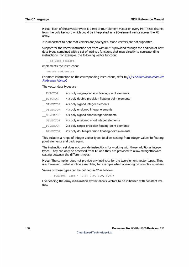
8/9/2019 SDK Reference Manual 3.1 Rev2.B
http://slidepdf.com/reader/full/sdk-reference-manual-31-rev2b 138/204
The Cn language SDK Reference Manual
138 Document No. 06-RM-1600 Revision: 2.B
ClearSpeed Technology Ltd
Note: Each of these vector types is a two or four-element vector on every PE. This is distinctfrom the poly keyword which could be interpreted as a 96-element vector across the PEarray.
It is important to note that vectors are poly types. Mono vectors are not supported.
Support for the vector instruction set from within Cn is provided through the addition of newdata types combined with a set of intrinsic functions that map directly to correspondinginstructions. For example, the following vector function:
__cs_vadd_scalar()
implements the instruction:
vector.add.scalar
For more information on the corresponding instructions, refer to [1]: CSX600 Instruction SetReference Manual .
The vector data types are:
__FVECTOR
__DVECTOR
__SIVECTOR
__UIVECTOR
__SSVECTOR
__USVECTOR
__F2VECTOR
__D2VECTOR
This includes a range of integer vector types to allow casting from integer values to floatingpoint elements and back again.
The instruction set does not provide instructions for working with these additional integertypes. They can only be accessed from Cn and they are provided to allow straightforwardcasting between the different types.
Note: The compiler does not provide any intrinsics for the two-element vector types. Theyare, however, useful in inline assembler, for example when operating on complex numbers.
Values of these types can be defined in Cn as follows:
__FVECTOR vacc = {0.0, 0.0, 0.0, 0.0};
Overloading the array initialization syntax allows vectors to be initialized with constant val-ues.
4 x poly single-precision floating-point elements
4 x poly double-precision floating-point elements
4 x poly signed integer elements
4 x poly unsigned integer elements
4 x poly signed short integer elements
4 x poly unsigned short integer elements
2 x poly single-precision floating-point elements
2 x poly double-precision floating-point elements

8/9/2019 SDK Reference Manual 3.1 Rev2.B
http://slidepdf.com/reader/full/sdk-reference-manual-31-rev2b 139/204
SDK Reference Manual The Cn language
Document No. 06-RM-1600 Revision: 2.B 139
ClearSpeed Technology Ltd
Vector assignment and the loading and storing from arrays are supported as normal. Forexample, the following piece of code loads four vectors from a poly array of single precisionfloats:
poly float V[BUFFERSIZE];
__FVECTOR v0;__FVECTOR v1;__FVECTOR v2;__FVECTOR v3;poly float *v = &V[0];
v0 = *((__FVECTOR *)v);v1 = *((__FVECTOR *)(v+4));
v2 = *((__FVECTOR *)(v+8));v3 = *((__FVECTOR *)(v+12));
Unlike other types in Cn, such as int and float, the standard arithmetic operators are not sup-ported. A set of built-in operations is provided instead. To square the vector v0, from theexample above, and add the result to an accumulator vacc , the following vector function
can be used: vacc = __cs_vmulacc(vacc, v0,v0);
It is important to note that this call maps directly to the vector instruction set, as defined inthe [1]: CSX600 Instruction Set Reference Manual and does not have the overhead of a func-tion call.
A more complete example of using vector instructions from Cn can be found in: exam-ples/sdk/cn_vector/square.cn in the SDK install directory.
11.13 Operator overloading
Unless specified, all operands and return value must have the same vector type.
Where the operands are a vector type and a scalar type, the scalar type must match the ele-ment type of the vector (float for __FVECTOR, double for __DVECTOR, for example), if monoscalar types are used, the scalar will be promoted to poly prior to the operation.
The actual set of operators, assignments and casts is as follows:
Operator Supported
vectorsResult type Description
vector1+vector2 _FVECTOR,
_DVECTORvector
Adds corresponding elements of the operand
vectors producing a vector result
vector1 + scalar orscalar + vector2
_FVECTOR, _DVECTOR
vector Adds the scalar to each element of vector1,producing a vector result
vector1 += vector2 _FVECTOR,
_DVECTORvector
Adds corresponding elements of vector1 and
vector2 assigning the resulting vector to vector1
vector1 += vector _FVECTOR,
_DVECTORvector
Adds the scalar to each element of vector1,
assigning the result to vector1
vector1 - vector2 _FVECTOR,
_DVECTORvector
Subtracts the corresponding elements of vector2
from those of vector1, producing a vector result
Table 30. Arithmetic operators

8/9/2019 SDK Reference Manual 3.1 Rev2.B
http://slidepdf.com/reader/full/sdk-reference-manual-31-rev2b 140/204
The Cn language SDK Reference Manual
140 Document No. 06-RM-1600 Revision: 2.B
ClearSpeed Technology Ltd
vector1 - scalar _FVECTOR,
_DVECTORvector
Subtracts the scalar from each element of
vector1, producing a vector result
scalar - vector1 _FVECTOR,
_DVECTORvector
Subtracts each element of vector1 from the
scalar producing a vector result
vector -= scalar _FVECTOR,
_DVECTORvector
Subtracts the scalar from each element of
vector1, the result of each subtraction being
placed in the corresponding element of vector1
vector1 * scalar or
scalar * vector1 _FVECTOR,
_DVECTORvector
Multiplies each element of vector1 by the scalar
producing a vector result
vector1 *= vector2 _FVECTOR,
_DVECTORvector
Multiplies the corresponding elements of vector1
and vector2 assigning the resulting vector to
vector1
vector1 *= scalar _FVECTOR, _DVECTOR
vector Multiplies each element of vector1 by the scalarassigning the vector result to vector1
Operator Supported
typesResult type Description
(_FVECTOR)vector1
_DVECTOR,
_SIVECTOR,
_UIVECTOR,
_SSVECTOR,
_USVECTOR
_FVECTOR
Casts the elements of vector1 to float, assigning
each cast to the corresponding element of the
result vector
(_FVECTOR)scalar Any scalar type _FVECTOR Casts the scalar to float and then assigns theresulting value to each element of the result
factor
(_DVECTOR)vector1
_DVECTOR,
_SIVECTOR,
_UIVECTOR,
_SSVECTOR,
_USVECTOR
_DVECTOR
Casts the elements of vector1 to double,
assigning each cast to the corresponding
element of the result vector
(_DVECTOR)scalar Any scalar type _DVECTOR
Casts the scalar to double and then assigns the
resulting value to each element of the result
vector
(_SIVECTOR)vector1 _FVECTOR,
_DVECTOR
_SIVECTORCasts each element of vector1 to signed int,
producing a vector result
(_UIVECTOR)vector1 _FVECTOR,
_DVECTOR _UIVECTOR
Casts each element of vector1 to unsigned int,
producing a vector result
(_SSVECTOR)vector1 _FVECTOR,
_DVECTOR _SSVECTOR
Casts each element of vector1 to signed short,
producing a vector result
(_USVECTOR)vector1 _FVECTOR,
_DVECTOR _USVECTOR
Casts each element of vector1 to unsigned
short, producing a vector result
Table 31. Type cast operators
Operator Supported
vectorsResult type Description
Table 30. Arithmetic operators
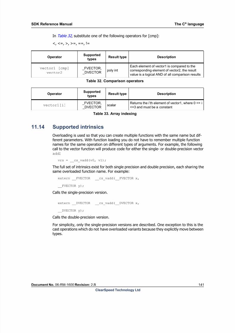
8/9/2019 SDK Reference Manual 3.1 Rev2.B
http://slidepdf.com/reader/full/sdk-reference-manual-31-rev2b 141/204
SDK Reference Manual The Cn language
Document No. 06-RM-1600 Revision: 2.B 141
ClearSpeed Technology Ltd
In Table 32 , substitute one of the following operators for [cmp]:
<, <=, >, >=, ==, !=
11.14 Supported intrinsics
Overloading is used so that you can create multiple functions with the same name but dif-ferent parameters. With function loading you do not have to remember multiple functionnames for the same operation on different types of arguments. For example, the followingcall to the vector function will produce code for either the single- or double-precision vectoradd:
vrs = __cs_vadd(v0, v1);
The full set of intrinsics exist for both single precision and double precision, each sharing thesame overloaded function name. For example:
extern __FVECTOR __cs_vadd(__FVECTOR x,
__FVECTOR y);
Calls the single-precision version.
extern __DVECTOR __cs_vadd(__DVECTOR x,
__DVECTOR y);
Calls the double-precision version.
For simplicity, only the single-precision versions are described. One exception to this is thecast operations which do not have overloaded variants because they explicitly move betweentypes.
Operator Supportedtypes
Result type Description
vector1 [cmp]
vector2 _FVECTOR,
_DVECTORpoly int
Each element of vector1 is compared to the
corresponding element of vector2, the result
value is a logical AND of all comparison results
Table 32. Comparison operators
Operator Supported
typesResult type Description
vector1[i] _FVECTOR,
_DVECTORscalar
Returns the i’th element of vector1, where 0 <= i
<=3 and must be a constant
Table 33. Array indexing
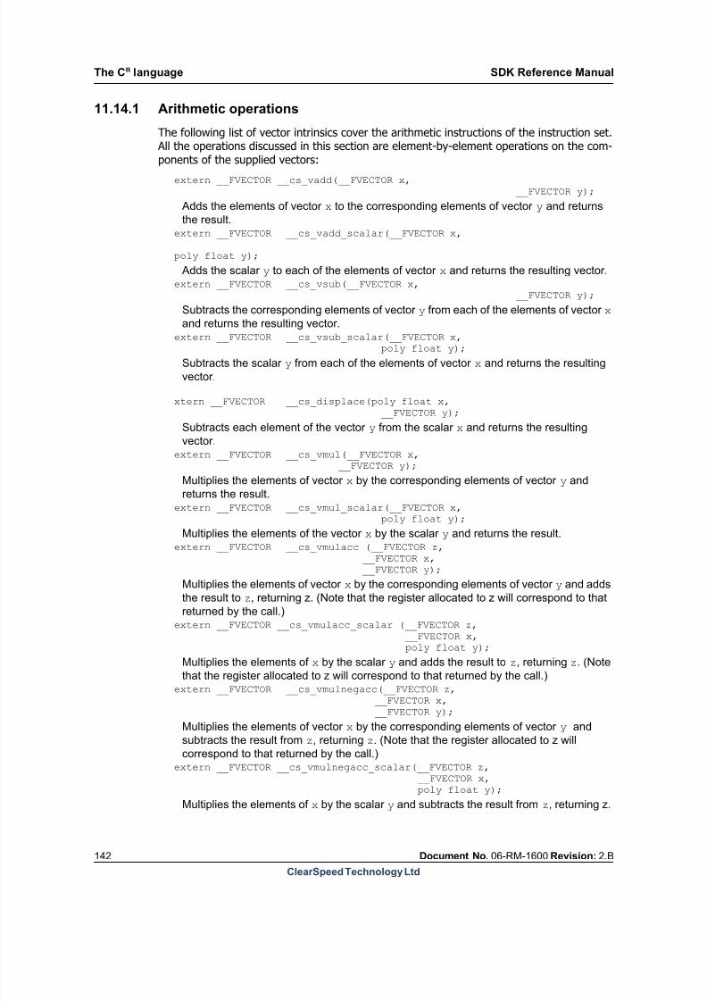
8/9/2019 SDK Reference Manual 3.1 Rev2.B
http://slidepdf.com/reader/full/sdk-reference-manual-31-rev2b 142/204
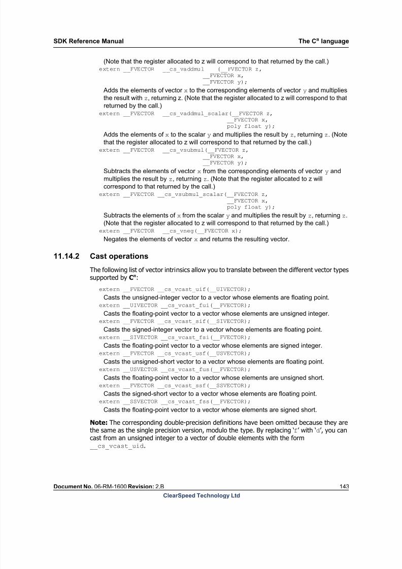
8/9/2019 SDK Reference Manual 3.1 Rev2.B
http://slidepdf.com/reader/full/sdk-reference-manual-31-rev2b 143/204
SDK Reference Manual The Cn language
Document No. 06-RM-1600 Revision: 2.B 143
ClearSpeed Technology Ltd
(Note that the register allocated to z will correspond to that returned by the call.)extern __FVECTOR __cs_vaddmul (__FVECTOR z, __FVECTOR x,
__FVECTOR y);
Adds the elements of vector x to the corresponding elements of vector y and multiplies
the result with z, returning z. (Note that the register allocated to z will correspond to that
returned by the call.)extern __FVECTOR __cs_vaddmul_scalar(__FVECTOR z, __FVECTOR x,
poly float y);
Adds the elements of x to the scalar y and multiplies the result by z, returning z. (Note
that the register allocated to z will correspond to that returned by the call.)extern __FVECTOR __cs_vsubmul(__FVECTOR z, __FVECTOR x,
__FVECTOR y);
Subtracts the elements of vector x from the corresponding elements of vector y and
multiplies the result by z, returning z. (Note that the register allocated to z will
correspond to that returned by the call.)extern __FVECTOR __cs_vsubmul_scalar(__FVECTOR z, __FVECTOR x,
poly float y);
Subtracts the elements of x from the scalar y and multiplies the result by z, returning z.
(Note that the register allocated to z will correspond to that returned by the call.)extern __FVECTOR __cs_vneg(__FVECTOR x);
Negates the elements of vector x and returns the resulting vector.
11.14.2 Cast operations
The following list of vector intrinsics allow you to translate between the different vector typessupported by Cn:
extern __FVECTOR __cs_vcast_uif(__UIVECTOR);
Casts the unsigned-integer vector to a vector whose elements are floating point.extern __UIVECTOR __cs_vcast_fui(__FVECTOR);
Casts the floating-point vector to a vector whose elements are unsigned integer.extern __FVECTOR __cs_vcast_sif(__SIVECTOR);
Casts the signed-integer vector to a vector whose elements are floating point.extern __SIVECTOR __cs_vcast_fsi(__FVECTOR);
Casts the floating-point vector to a vector whose elements are signed integer.extern __FVECTOR __cs_vcast_usf(__USVECTOR);
Casts the unsigned-short vector to a vector whose elements are floating point.extern __USVECTOR __cs_vcast_fus(__FVECTOR);
Casts the floating-point vector to a vector whose elements are unsigned short.extern __FVECTOR __cs_vcast_ssf(__SSVECTOR);
Casts the signed-short vector to a vector whose elements are floating point.extern __SSVECTOR __cs_vcast_fss(__FVECTOR);
Casts the floating-point vector to a vector whose elements are signed short.
Note: The corresponding double-precision definitions have been omitted because they arethe same as the single precision version, modulo the type. By replacing ‘f’ with ‘d’, you cancast from an unsigned integer to a vector of double elements with the form__cs_vcast_uid.
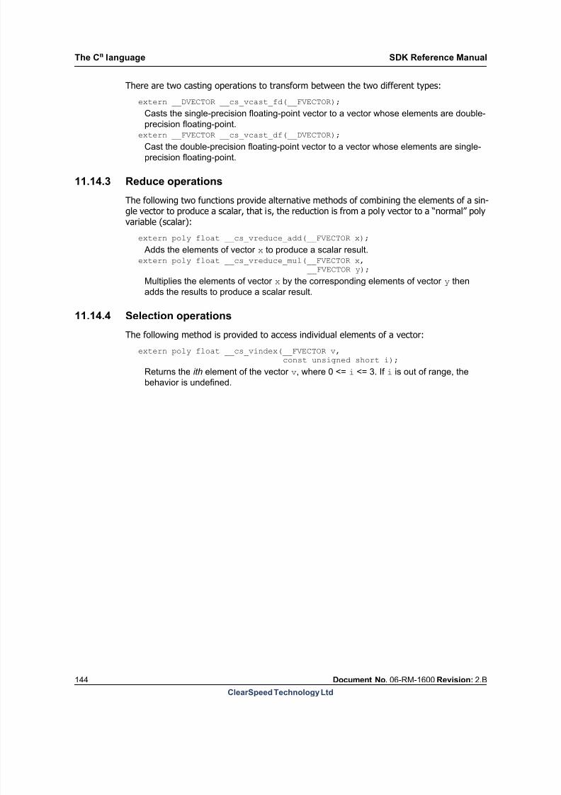
8/9/2019 SDK Reference Manual 3.1 Rev2.B
http://slidepdf.com/reader/full/sdk-reference-manual-31-rev2b 144/204
The Cn language SDK Reference Manual
144 Document No. 06-RM-1600 Revision: 2.B
ClearSpeed Technology Ltd
There are two casting operations to transform between the two different types:
extern __DVECTOR __cs_vcast_fd(__FVECTOR);
Casts the single-precision floating-point vector to a vector whose elements are double-
precision floating-point.
extern __FVECTOR __cs_vcast_df(__DVECTOR);
Cast the double-precision floating-point vector to a vector whose elements are single-
precision floating-point.
11.14.3 Reduce operations
The following two functions provide alternative methods of combining the elements of a sin-gle vector to produce a scalar, that is, the reduction is from a poly vector to a “normal” polyvariable (scalar):
extern poly float __cs_vreduce_add(__FVECTOR x);
Adds the elements of vector x to produce a scalar result.extern poly float __cs_vreduce_mul(__FVECTOR x,
__FVECTOR y);
Multiplies the elements of vector x by the corresponding elements of vector y then
adds the results to produce a scalar result.
11.14.4 Selection operations
The following method is provided to access individual elements of a vector:
extern poly float __cs_vindex(__FVECTOR v,const unsigned short i);
Returns the ith element of the vector v, where 0 <= i <= 3. If i is out of range, the
behavior is undefined.

8/9/2019 SDK Reference Manual 3.1 Rev2.B
http://slidepdf.com/reader/full/sdk-reference-manual-31-rev2b 145/204
SDK Reference Manual The Cn language
Document No. 06-RM-1600 Revision: 2.B 145
ClearSpeed Technology Ltd
11.14.5 Constructor operations
The final set of vector functions provide for the construction of vectors from a set of scalarvalues:
extern __FVECTOR __cs_vmconstructor(mono float a,mono float b,mono float c,mono float d);
Constructs the vector {a, b, c, d} and returns the result.
extern __DVECTOR __cs_vmconstructor(mono double a,mono double b,mono double c,mono double d);
Constructs the vector {a, b, c, d} and returns the result.
extern __FVECTOR __cs_vpconstructor(poly float a,poly float b,
poly float c,poly float d);
Constructs the vector {a, b, c, d} and returns the result.
extern __DVECTOR __cs_vpconstructor(poly double a,poly double b,poly double c,poly double d);
Constructs the vector {a, b, c, d} and returns the result.
11.15 Reserved keywords
Table 34 shows the keywords reserved by the Cn compiler.
... do int struct
__asm
double
long
switch
asm else
mono
typedef
auto
enum
poly
union
break extern register
unsigned
case
float
return
volatile
char
for short
while
const
goto
signed
Table 34. Reserved keywords in Cn
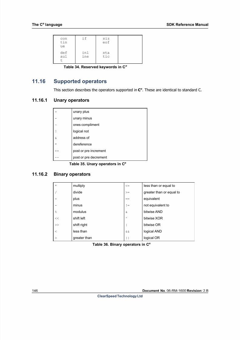
8/9/2019 SDK Reference Manual 3.1 Rev2.B
http://slidepdf.com/reader/full/sdk-reference-manual-31-rev2b 146/204
The Cn language SDK Reference Manual
146 Document No. 06-RM-1600 Revision: 2.B
ClearSpeed Technology Ltd
11.16 Supported operators
This section describes the operators supported in Cn. These are identical to standard C.
11.16.1 Unary operators
11.16.2 Binary operators
continue
if sizeof
def
ault
inl
ine
sta
tic
Table 34. Reserved keywords in Cn
+ unary plus
- unary minus
~ ones compliment
! logical not
& address of
* dereference
++ post or pre increment
-- post or pre decrement
Table 35. Unary operators in Cn
* multiply <= less than or equal to
/ divide >= greater than or equal to
+ plus == equivalent
- minus != not equivalent to
% modulus & bitwise AND
<< shift left ^ bitwise XOR
>> shift right | bitwise OR
< less than && logical AND
> greater than || logical OR
Table 36. Binary operators in Cn
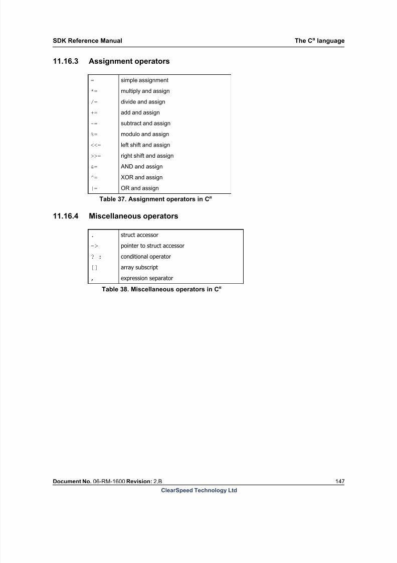
8/9/2019 SDK Reference Manual 3.1 Rev2.B
http://slidepdf.com/reader/full/sdk-reference-manual-31-rev2b 147/204
SDK Reference Manual The Cn language
Document No. 06-RM-1600 Revision: 2.B 147
ClearSpeed Technology Ltd
11.16.3 Assignment operators
11.16.4 Miscellaneous operators
. struct accessor
-> pointer to struct accessor
? : conditional operator
[] array subscript
, expression separator
= simple assignment
*=multiply and assign
/= divide and assign
+= add and assign
-= subtract and assign
%= modulo and assign
<<= left shift and assign
>>= right shift and assign
&= AND and assign
^= XOR and assign
|= OR and assign
Table 37. Assignment operators in Cn
Table 38. Miscellaneous operators in Cn
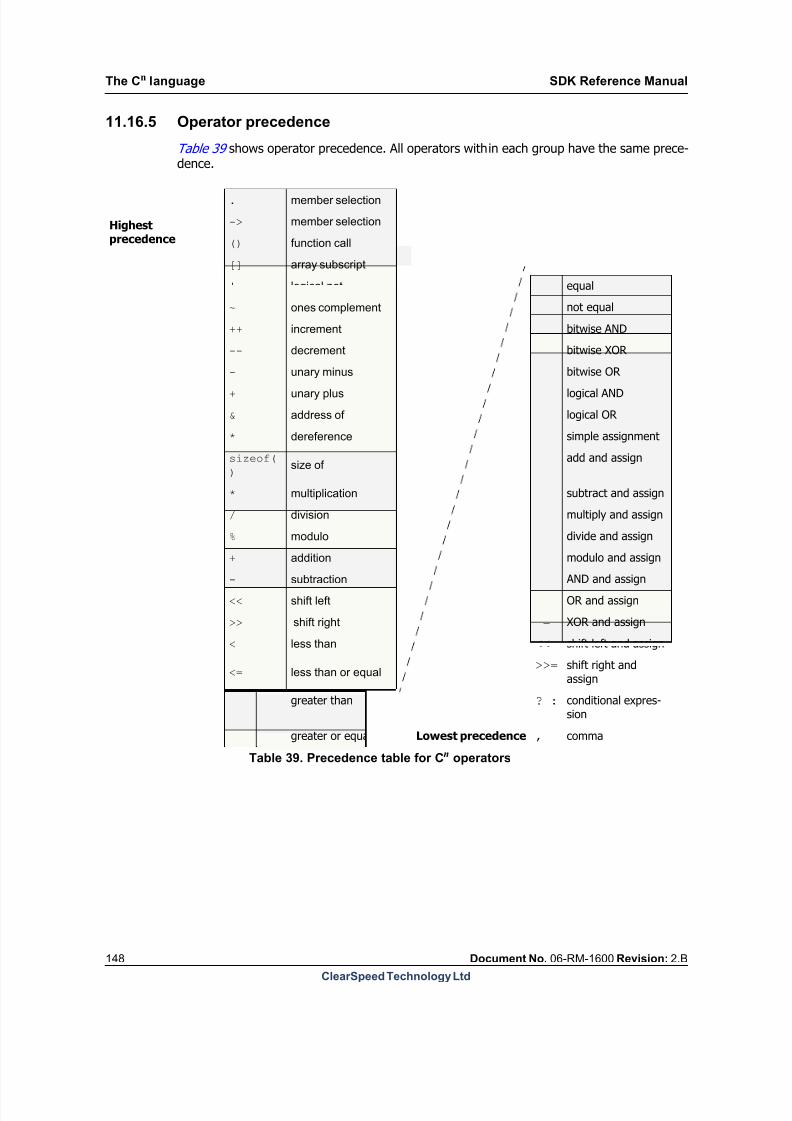
8/9/2019 SDK Reference Manual 3.1 Rev2.B
http://slidepdf.com/reader/full/sdk-reference-manual-31-rev2b 148/204
The Cn language SDK Reference Manual
148 Document No. 06-RM-1600 Revision: 2.B
ClearSpeed Technology Ltd
11.16.5 Operator precedence
Table 39 shows operator precedence. All operators within each group have the same prece-dence.
== equal
!= not equal
& bitwise AND
^ bitwise XOR
| bitwise OR && logical AND
|| logical OR
= simple assignment
+= add and assign
-= subtract and assign
*= multiply and assign
/= divide and assign
%= modulo and assign&= AND and assign
|= OR and assign
^= XOR and assign
<<= shift left and assign
>>= shift right andassign
> greater than ? : conditional expres-sion
>= greater or equal Lowest precedence , comma
Highestprecedence
. member selection
-> member selection
() function call
[] array subscript
! logical not
~ ones complement
++ increment
-- decrement
- unary minus+ unary plus
& address of
* dereference
sizeof(
)size of
* multiplication
/ division
% modulo
+ addition- subtraction
<< shift left
>> shift right
< less than
<= less than or equal
Table 39. Precedence table for Cn operators
8/9/2019 SDK Reference Manual 3.1 Rev2.B
http://slidepdf.com/reader/full/sdk-reference-manual-31-rev2b 149/204
SDK Reference Manual The Cn language
Document No. 06-RM-1600 Revision: 2.B 149
ClearSpeed Technology Ltd
8/9/2019 SDK Reference Manual 3.1 Rev2.B
http://slidepdf.com/reader/full/sdk-reference-manual-31-rev2b 150/204
Memory use SDK Reference Manual
150 Document No. 06-RM-1600 Revision: 2.B
ClearSpeed Technology Ltd
12 Memory use
This chapter describes some of the options available in the SDK for managing the use of
meory by the CSX processor.
12.1 Stack allocation
Each thread executing in a program will probably require a mono and a poly stack.
In the 3.0 release, stacks are automatically created for the main execution thread (thread 0)and these stacks are dynamically sized. As the program runs, more stack space will be used,up to the limit of available memory. Run-time stack checking can be enabled to ensure thatthe stack usage does not exceed available memory.
Thread 7 is used by the asynchronous memcpy functions. Mono and poly stacks of zero size
are allocated for this thread.
No thread is defined for threads 1 to 6. It is the programmers responsibility to define stacksfor these threads if they are used.
If you use any other threads in your program then you must allocate mono and poly stacksfor each thread. Normally, these stacks will be assigned fixed sizes and allocated statically.
One mono stack and one poly stack can be defined to be managed dynamically. By default,these are allocated to thread 0. If you wish to assign a dynamic stack to another thread thenyou must first assign a static stack for thread 0. To define a dynamic stack for a thread, youshould set the stack size to -1. This will convert the stack to a dynamic stack (1). If you definetwo threads with dynamic stacks in the same domain (that is, two mono or two poly dynamicstacks) this will cause a run-time error.
12.1.1 Stack size definition
By default, the mono and poly stacks for the main execution thread (thread 0) are dynami-cally sized, up to the maximum available memory. If a size is specified for these stacks thenthey will become static, with a fixed size.
In many cases, the use of a dynamic stack for the main execution thread in the 3.0 releasemay remove the need to explicitly specify the size of the stacks.
In the previous SDK releases, stacks had to be creating by defining an appropriate symbol,typically by creating an assembler source code file containing the necessary definitions andthen linking this with your program.
With this release, the size of statically allocated stacks can be defined in a number of differentways. You can use whichever method is most convenient for your application and develop-ment process.
The size of the stacks can be specified in any compilation unit making up an executable. How-ever, any particular stack must only be specified once.
1. This does not work with the Cn pragma described below.
8/9/2019 SDK Reference Manual 3.1 Rev2.B
http://slidepdf.com/reader/full/sdk-reference-manual-31-rev2b 151/204
SDK Reference Manual Memory use
Document No. 06-RM-1600 Revision: 2.B 151
ClearSpeed Technology Ltd
Command line options
The compiler has a set of command line options for specifying the sizes of the stacks for eachthread. See Section 2.4.3: Compiler options on page 22 for details.
The command line options are of the form:--set-mono-stack-size-thread-n size--set-poly-stack-size-thread-n size
Where n is the thread number that a stack is being defined for and size is the size of thestack in bytes.
Cn pragmas
A Cn pragma is also provided for setting the stack size, as follows:
#pragma static_stack(mono|poly, size, thread )
The first argument defines whether a mono or poly stack size is being defined. The second
argument specifies the stack size in bytes. The third argument specifies the thread numberfor which the stack size is being set.
Note: This pragma does not accept -1 as a stack size to define a dynamically allocatedstacks: use one of the other methods for this.
Assembly code
Note: The other methods of specifying the stack size all map on to this underlying mecha-nism by causing the compiler to emit the necessary directives to define the stacks.
The mechanism for specifying the size of stacks in assembler code has changed. Instead ofdefining the stacks in the mono and poly bss sections using the .fill command, you now
use the .set directive to specify the size of the stack you need. The runtime allocates thisspace when the executable is loaded.
For example, previously you would have included code similar to the following fragment inyour program:
.section .mono.bss__FRAME_BEGIN_MONO__3::.global __FRAME_BEGIN_MONO__3.fill 1024, 1, 0x0
This creates a 1 KB mono stack frame for thread 3 in the mono bss section.
The new method of declaring this is to use a .set command as shown below:
.set __FRAME_BEGIN_MONO__3, 1024
.global __FRAME_BEGIN_MONO__3
This will cause the runtime to allocate an area of this size for the stack at load time and assignall necessary pointers to this point. All stacks, both mono and poly, can be declared in thismanner.
Note: The same symbols are used to define the stack sizes as were previously used to definethe start address of the stack. Therefore, your program will fail to run correctly if you do notchange, or remove, the old code for specifying stack sizes.

8/9/2019 SDK Reference Manual 3.1 Rev2.B
http://slidepdf.com/reader/full/sdk-reference-manual-31-rev2b 152/204
Memory use SDK Reference Manual
152 Document No. 06-RM-1600 Revision: 2.B
ClearSpeed Technology Ltd
12.2 Stack checking
This release also includes support for run-time checking of stack usage. There are two typesof checks that can be performed: a static, compile time, check on the maximum size of any
functions stack frame; secondly, a run-time check that the program does not run past theend of the available memory.
12.2.1 Run-time stack checking
The option dynamic-stack-check turns on run-time checking of mono and poly stackusage for all threads. This causes the compiler to add code the entry point of every functionto check that the function’s stack frames will not cause the stacks to overrun available mem-ory. This can have a significant performance penalty and so is turned off by default. Thisoption should only be used when developing or debugging software.
For statically allocated stacks, this checks that the mono and poly stack frames for a functionwill not exceed the size specified for the stack.
For dynamically allocated stacks, this checks that the mono and poly stack frames for a func-tion will not cause the stack to grow beyond the available memory. For the mono stack thismeans that the stack will not overrun the heap (which grows from the top of memory). Forthe poly stack, it checks that the stack will not grow past the end of poly memory.
If these checks fail then the runtime will display a warning on the console when that functionis called.
12.2.2 Stack frame size checking
The compler can also check (at compile time) that the stack frame for any function does notexceed a given size. This is a simple test that does affect performance and gives some con-
fidence that stack usage is not grossly excessive. This check can be turned on using the com-piler command line options check-mono-frame and check-poly-frame.
The default limits for stack frame sizes are 64 KB for mono and 3 KB for poly. These limitscan be changed with the command line options check-mono-frame-size and check-
poly-frame-size.
If this check fails, then the compiler will generate a warning. You can cause the compiler toreport an error when the check fails by using the error-mono-frame or error-poly-frame options.
12.3 Support for ECC memory
Future ClearSpeed processors will include memory with error correcting codes (ECC) forgreater reliability. This applies to both the on-chip SRAM and the poly memory (in additionto the current ECC support for external DRAM). The use of ECC memory introduces someconstraints on the way that memory can be accessed. Stores to memory which are the samewidth as the ECC word are not affected. Stores which are narrower than this need to performa read-modify-write of the whole word to avoid causing an ECC error.
Support for ECC memory in future products is being introduced in this release of the SDK toavoid future compatibility changes.

8/9/2019 SDK Reference Manual 3.1 Rev2.B
http://slidepdf.com/reader/full/sdk-reference-manual-31-rev2b 153/204
SDK Reference Manual Memory use
Document No. 06-RM-1600 Revision: 2.B 153
ClearSpeed Technology Ltd
On-chip SRAM memory will have 32-bit ECC and so a simple store must be 32 bits wide. Ifyou wish to write 16-bit data or a single byte to this memory then you will have to read the32-bit word from memory, modify the bytes to be written and write the whole word back.
Poly memory will have 16-bit ECC. The poly load and store instructions have been modified
to perform a read-modify-write cycle for all one-byte stores. These instruction will thereforebe slower in this release. All poly one-byte stores now also require additional temporary reg-isters in order to perform this read modify write logic. Table 40 lists the temporary registersrequired.
Table 40. Temporaries required
If you are writing code which will only be run on a processor without ECC poly memory, thenit is possible to make the tools use the old single-byte store instructions. These do not do aread-modify-write and so are faster.
You can force the compiler to use the non-ECC store instructions using the cscn commandline option --no-poly-ecc.
You can make the assembler use the old style store instructions by inserting the followingpragma at the top of your assembler source code file.
.pragma non_ecc_st on
12.4 Advance card memory map
This section describes the memory map used by the Advance accelerator cards.
Each processor on the Advance X620 and Advance e620 cards has 512 MBytes of DDR2-400DRAM directly connected. The DRAM is 72 bits wide, including 8 bits of error correcting code(ECC). This allows correction of single-bit errors and detection of most multiple-bit errors.
Store type Sub type
Mono
temporary
registers
Poly
temporary
registers
Non-ECC ECC
Store
Immediate address
Immediate address, mono offset
Mono address, no offset
Mono address, with offset
Poly address, no offset
Poly address, with offset
2
2
2
2
00
3
3
3
3
55
2
1
1
1
22
13
12
12
12
1717
Indexed store
Immediate address
Mono address, no offset
Mono address, with offset
0
0
0
5
5
5
1
1
1
17
16
18
Forced store
Immediate address
Immediate address, mono offset
Mono address, no offset
Mono address, with offset
Poly address, no offset
Poly address, with offset
2
2
2
2
0
0
4
4
4
4
6
6
2
1
1
1
2
2
19
19
18
19
23
23
Forced indexed store
Immediate address
Mono address, no offset Mono address, with offset
0
00
6
66
2
11
23
2224
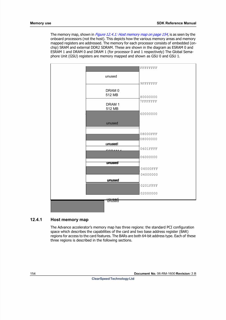
8/9/2019 SDK Reference Manual 3.1 Rev2.B
http://slidepdf.com/reader/full/sdk-reference-manual-31-rev2b 154/204
Memory use SDK Reference Manual
154 Document No. 06-RM-1600 Revision: 2.B
ClearSpeed Technology Ltd
The memory map, shown in Figure 12.4.1: Host memory map on page 154 , is as seen by theonboard processors (not the host). This depicts how the various memory areas and memorymapped registers are addressed. The memory for each processor consists of embedded (on-chip) SRAM and external DDR2 SDRAM. These are shown in the diagram as ESRAM 0 and
ESRAM 1 and DRAM 0 and DRAM 1 (for processor 0 and 1 respectively) The Global Sema-phore Unit (GSU) registers are memory mapped and shown as GSU 0 and GSU 1.
12.4.1 Host memory map
The Advance accelerator’s memory map has three regions: the standard PCI configurationspace which describes the capabilities of the card and two base address register (BAR)regions for access to the card features. The BARs are both 64-bit address type. Each of thesethree regions is described in the following sections.
FFFFFFFF
9FFFFFFF
DRAM 0
512 MB
DRAM 1
512 MB
unused
GSU 1
unused
ESRAM 1
128 KB
unused
GSU 0
unused
unused
ESRAM 0
128 KB
80000000
7FFFFFFF
60000000
08000FFF
08000000
0601FFFF
06000000
04000FFF
04000000
0201FFFF
02000000
00000000
unused
unused
unused
unused
unused
unused
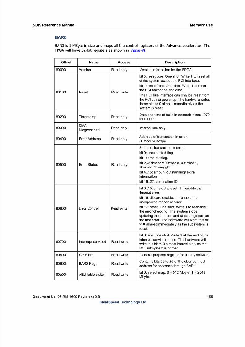
8/9/2019 SDK Reference Manual 3.1 Rev2.B
http://slidepdf.com/reader/full/sdk-reference-manual-31-rev2b 155/204
SDK Reference Manual Memory use
Document No. 06-RM-1600 Revision: 2.B 155
ClearSpeed Technology Ltd
BAR0
BAR0 is 1 MByte in size and maps all the control registers of the Advance accelerator. TheFPGA will have 32-bit registers as shown in Table 41
Offset Name Access Description
80000 Version Read only Version information for the FPGA.
80100 Reset Read write
bit 0: reset core. One shot. Write 1 to reset all
of the system except the PCI interface.
bit 1: reset front. One shot. Write 1 to reset
the PCI halfbridge and dma.
The PCI bus interface can only be reset from
the PCI bus or power up. The hardware writes
these bits to 0 almost immediately as the
system is reset.
80200 Timestamp Read only Date and time of build in seconds since 1970-01-01 00:
80300DMA
Diagnostics 1Read only Internal use only.
80400 Error Address Read only Address of transaction in error.
(Timeout/unexpe
80500 Error Status Read only
Status of transaction in error.
bit 0: unexpected flag.
bit 1: time out flag.
bit 2,3: dmabar: 00=bar 0, 001=bar 1,
10=dma, 11=arggh
bit 4..15: amount outstanding/ extra
information.
bit 16..27: destination ID
80600 Error Control Read write
bit 0..15: time out preset: 1 = enable the
timeout error.
bit 16: discard enable: 1 = enable the
unexpected response error.
bit 17: reset. One shot. Write 1 to reenable
the error checking. The system stops
updating the address and status registers on
the first error. The hardware will write this bit
to 0 almost immediately as the subsystem is
reset.
80700 Interrupt serviced Read write
bit 0: eoi. One shot. Write 1 at the end of the
interrupt service routine. The hardware will
write this bit to 0 almost immediately as the
MSI subsystem is primed.
80800 GP Store Read write General purpose register for use by software.
80900 BAR2 Page Read writeContains bits 56 to 25 of the clear connect
address for accesses through BAR1.
80a00 AEU table switch Read writebit 0: select map. 0 = 512 Mbyte, 1 = 2048
Mbyte.

8/9/2019 SDK Reference Manual 3.1 Rev2.B
http://slidepdf.com/reader/full/sdk-reference-manual-31-rev2b 156/204

8/9/2019 SDK Reference Manual 3.1 Rev2.B
http://slidepdf.com/reader/full/sdk-reference-manual-31-rev2b 157/204
SDK Reference Manual Application binary interface
Document No. 06-RM-1600 Revision: 2.B 157
ClearSpeed Technology Ltd
13 Application binary interface
This chapter describes the Application Binary Interface (ABI) for the ClearSpeed tool chain.
The following definitions apply in the text that follows: Byte = 8 bits.
Word = 16 bits.
Double Word = 32 bits.
Quad Word = 64 bits.
13.1 Overview of the ABI
An ABI is the set of rules that software must obey in order to interact with other compiledcomponents.
The ABI defines a set of runtime interfaces between compiled software components, or soft-ware components that must interact with other ABI compliant software. An ABI differs froman Application Programming Interface (API) in that an API is a build time interface that isusually defined as a set of prototypes of library functions.
The ABI also defines a system level interface for compiled programs. The purpose of the ABIis to provide a set of rules that enable the object files and libraries to be shared across variousdevelopment environments and languages and the executables to be loaded and executed.
Note: The ABI is a convention only, but it is necessary for compatibility with the ClearSpeedSDK.
13.2 Process startup
An application depends on a loader to set up and run the program on a target device or sim-ulator. A loader calls the program entry point recorded in the object file. By default, this isthe symbol _start defined in the Cn runtime library. The SDK tools use this symbol as theplace to start execution when code is loaded and run.
The initialization tasks performed by the operating system on program loading include:
Booting the processor (loading the program into memory, initializing the processor’s
control registers, and so on).
Allocating mono memory for the mono variable stack and poly memory for the poly
variable stack (the sizes of the stacks are provided by the object file).
Initializing the mono_sp and poly_sp registers to set up the mono and poly stack
pointers respectively; these are both mono registers.
Starting the execution of the application.
See [7]: ClearSpeed CSX600 Hardware Programming Manual for details of the startup pro-cess.

8/9/2019 SDK Reference Manual 3.1 Rev2.B
http://slidepdf.com/reader/full/sdk-reference-manual-31-rev2b 158/204
Application binary interface SDK Reference Manual
158 Document No. 06-RM-1600 Revision: 2.B
ClearSpeed Technology Ltd
13.2.1 Multithreaded code
In order to support multithreaded code, entry points are defined for each thread. These are_start, _start1, . . . _start7 , that correspond to the number of threads supported bythe processor. The default entry point, _start, corresponds to the lowest priority thread.The entry point _start7 corresponds to thread 0, the highest priority.
The standard entry point is the lowest priority thread because some threads used in the sys-tem have to operate at a higher priority (for example, debug and async I/O) consequently itis convenient to default user programs to lower priority threads; a user can specify higherpriority threads if necessary. See [7]: ClearSpeed CSX600 Hardware Programming Manual for greater detail.
13.2.2 Program termination
When a program terminates normally, it returns control to the runtime system. The exit codeis contained in the mono return register and is the exit value of the program. This is usually
zero to indicate normal termination.
13.3 Data representation and allocation
The text that follows describes how various types of data are stored in memory.
The ABI assumes that data is stored in the endianness (see Section 13.7: Endianness on page 175 ) chosen for the processor. Consequently, where data is shared with another devicewith different endianness, one device reorders the bytes to compensate.
13.3.1 Data types
The sizes and alignment of supported data types are described in the text that follows.
Scalar types
Table 42 shows the size and alignment of scalar and vector types in memory.
Note: Scalar types in registers and memory must be naturally aligned, for example, a valueof type int is 4-byte aligned in memory and in registers that are a multiple of four bytes.Mono characters are naturally aligned to one byte in memory and are stored in mono regis-ters that are at least 2-byte aligned.
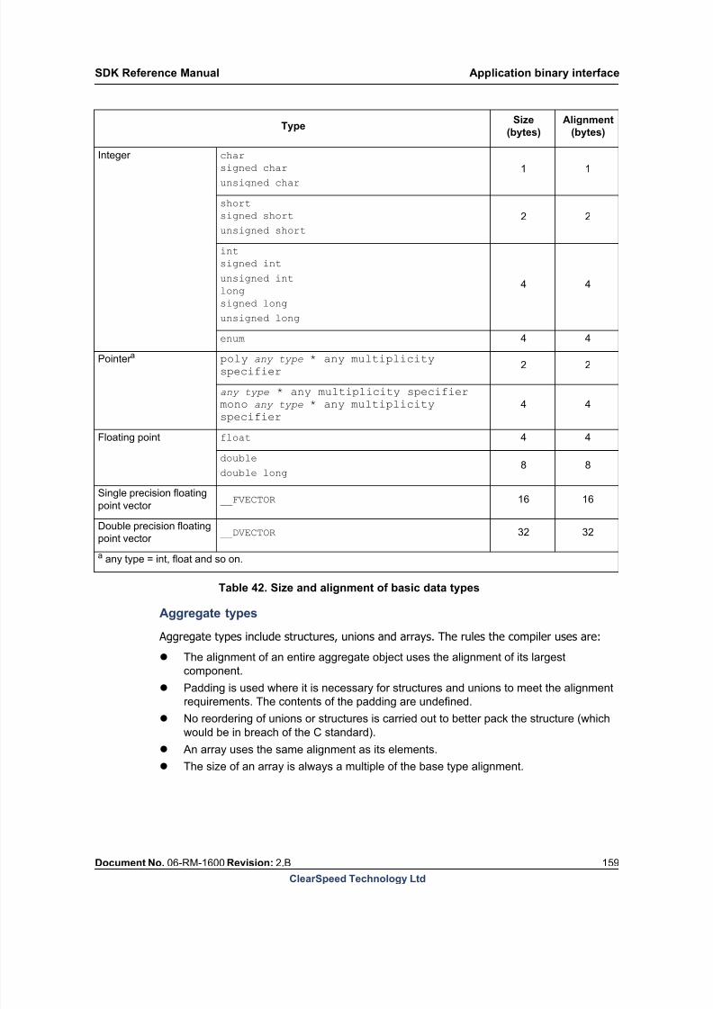
8/9/2019 SDK Reference Manual 3.1 Rev2.B
http://slidepdf.com/reader/full/sdk-reference-manual-31-rev2b 159/204
SDK Reference Manual Application binary interface
Document No. 06-RM-1600 Revision: 2.B 159
ClearSpeed Technology Ltd
Aggregate types
Aggregate types include structures, unions and arrays. The rules the compiler uses are:
The alignment of an entire aggregate object uses the alignment of its largest
component. Padding is used where it is necessary for structures and unions to meet the alignment
requirements. The contents of the padding are undefined.
No reordering of unions or structures is carried out to better pack the structure (which
would be in breach of the C standard).
An array uses the same alignment as its elements.
The size of an array is always a multiple of the base type alignment.
TypeSize
(bytes)
Alignment
(bytes)
Integer char
signed charunsigned char
1 1
short
signed short
unsigned short
2 2
int
signed int
unsigned int
long
signed long
unsigned long
4 4
enum 4 4
Pointer a poly any type * any multiplicityspecifier
2 2
any type * any multiplicity specifier
mono any type * any multiplicityspecifier
4 4
Floating point float 4 4
double
double long8 8
Single precision floating
point vector __FVECTOR 16 16
Double precision floating
point vector __DVECTOR 32 32
a any type = int, float and so on.
Table 42. Size and alignment of basic data types

8/9/2019 SDK Reference Manual 3.1 Rev2.B
http://slidepdf.com/reader/full/sdk-reference-manual-31-rev2b 160/204
Application binary interface SDK Reference Manual
160 Document No. 06-RM-1600 Revision: 2.B
ClearSpeed Technology Ltd
The key points are:
The alignment of a structure or union follows the alignment of the most coarsely
aligned member.
Each member is aligned to its own alignment at the lowest available offset. Padding is
used where required.
Bit fields are packed within the base type so that minimum space is used, maintaining
order and not crossing type boundaries.
Typical alignments are illustrated in Figure 21 to Figure 25 .
c
struct {
char c;
};
0
c
struct {
char c;
char d;
};
c
0
c
c
1
d
struct {
char c;
char d;
char e;
};
c
0
c
c
1 d
c
d e
2
Byte address
Figure 21.Structures smaller than a word

8/9/2019 SDK Reference Manual 3.1 Rev2.B
http://slidepdf.com/reader/full/sdk-reference-manual-31-rev2b 161/204
c
struct {
char c;
short s;
long n
};
0
c
Padding
c
4
c
1
d
Padding
c
2
Byte address
s
n
c Padding
c
0 1
4
018
12
i
s
n
struct {
char c;
int i;
short s;
long n
};
c
union {
char c;
short s;
int i;
};
0
c
Padding
1
Byte address
c Padding
0
2
i
s
0
SDK Reference Manual Application binary interface
Document No. 06-RM-1600 Revision: 2.B 161
ClearSpeed Technology Ltd
Figure 22.Structures larger than a word
Figure 23.Union allocation

8/9/2019 SDK Reference Manual 3.1 Rev2.B
http://slidepdf.com/reader/full/sdk-reference-manual-31-rev2b 162/204
c
struct {
int i:3;
int j:7;
int k:10;
}; 0
c
Padding
2
Bit number
0
i j
Byte address
19 9 203 10 31k
c
struct {
int i:3;
int j:7;
int k:10; short s;
short u:9;
char c;
};
0 c
Padding
2
0
i j
Byte address
19 9 203 10 31k
4
510 s 16 24u
Padding
3125
Padding
31
8
0 7 8c
struct {
char c;
short s:8
};
0
c0 7 8 15s
1
Bit number
Application binary interface SDK Reference Manual
162 Document No. 06-RM-1600 Revision: 2.B
ClearSpeed Technology Ltd
Figure 24.Bit fields: LSB to MSB allocation
Figure 25.Bit fields: boundary alignment
Enumeration types
Enumeration types are allocated as 4-byte unsigned integer values and are thus 4-bytealigned and restricted to the range 0 - 2^32-1.
13.3.2 Memory model
There are two separate memory spaces accessible in the processor architecture: mono mem-ory (for example, external DRAM attached through the memory interface) and poly memory.Poly memory is distributed across processing elements (PE), and is private to each PE. Thememory architecture is described in [6]: CSX600 Core Architecture Manual .
Mono load and store instructions transfer data between mono memory and the mono registerfile. Poly loads and stores move data between poly memory and the poly register file on thesame PE.

8/9/2019 SDK Reference Manual 3.1 Rev2.B
http://slidepdf.com/reader/full/sdk-reference-manual-31-rev2b 163/204
SDK Reference Manual Application binary interface
Document No. 06-RM-1600 Revision: 2.B 163
ClearSpeed Technology Ltd
Data is transferred between the mono and poly memory spaces using Programmed I/O(PIO). For details of the PIO function, see [8]: The C Programming Language . This function-ality is exposed to the Cn programmer by variants of the standard memcpy function.
The ABI reserves some words of poly memory as illustrated in Figure 26 .
Address 0
Address n-16 PE number
Reserved
Stack
4 bytes
12 bytes
Figure 26.Reserved poly memory locations for a PE with n bytes of memory
13.3.3 Register model
The general register assignment is listed in Table 44 and Table 43 .
Three operand instructions (for example, add r1, r2, r3) that use poly registers greaterthan 64 (the upper half of the register file) are required to have an alignment of 2, whichimplies that they are even and must be of size 2 bytes or greater. So any register argument,r, to a three operand poly instruction must obey:
all (r <64) or (r modulo 2 = 0 with size (r) >= 2)
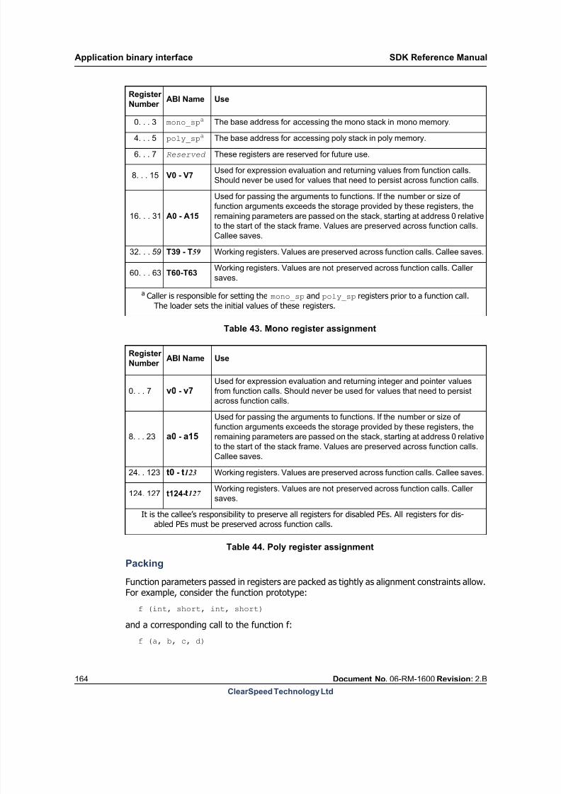
8/9/2019 SDK Reference Manual 3.1 Rev2.B
http://slidepdf.com/reader/full/sdk-reference-manual-31-rev2b 164/204
Application binary interface SDK Reference Manual
164 Document No. 06-RM-1600 Revision: 2.B
ClearSpeed Technology Ltd
Packing
Function parameters passed in registers are packed as tightly as alignment constraints allow.For example, consider the function prototype:
f (int, short, int, short)
and a corresponding call to the function f:
f (a, b, c, d)
Register
Number ABI Name Use
0. . . 3 mono_spa The base address for accessing the mono stack in mono memory.
4. . . 5 poly_spa The base address for accessing poly stack in poly memory.
6. . . 7 Reserved These registers are reserved for future use.
8. . . 15 V0 - V7Used for expression evaluation and returning values from function calls.
Should never be used for values that need to persist across function calls.
16. . . 31 A0 - A15
Used for passing the arguments to functions. If the number or size of
function arguments exceeds the storage provided by these registers, the
remaining parameters are passed on the stack, starting at address 0 relative
to the start of the stack frame. Values are preserved across function calls.
Callee saves.
32. . . 59 T39 - T59 Working registers. Values are preserved across function calls. Callee saves.
60. . . 63 T60-T63 Working registers. Values are not preserved across function calls. Callersaves.
a Caller is responsible for setting the mono_sp and poly_sp registers prior to a function call.The loader sets the initial values of these registers.
Table 43. Mono register assignment
Register
Number ABI Name Use
0. . . 7 v0 - v7Used for expression evaluation and returning integer and pointer values
from function calls. Should never be used for values that need to persist
across function calls.
8. . . 23 a0 - a15
Used for passing the arguments to functions. If the number or size of
function arguments exceeds the storage provided by these registers, the
remaining parameters are passed on the stack, starting at address 0 relative
to the start of the stack frame. Values are preserved across function calls.
Callee saves.
24. . 123 t0 - t123 Working registers. Values are preserved across function calls. Callee saves.
124. 127 t124-t127 Working registers. Values are not preserved across function calls. Caller
saves.
It is the callee’s responsibility to preserve all registers for disabled PEs. All registers for dis-abled PEs must be preserved across function calls.
Table 44. Poly register assignment

8/9/2019 SDK Reference Manual 3.1 Rev2.B
http://slidepdf.com/reader/full/sdk-reference-manual-31-rev2b 165/204
SDK Reference Manual Application binary interface
Document No. 06-RM-1600 Revision: 2.B 165
ClearSpeed Technology Ltd
The arguments are of different sizes, so the possibility exists to utilize register space moreefficiently. The arguments are passed to the function as illustrated in Figure 27 . The argu-ment d appears before c because it requires only 2-byte alignment, so the packing algorithmuses the first free location that is 2 bytes in size and alignment.
a a a a b b d d c c c c
Figure 27.Register packing
The packing algorithm operates as follows:
1. Take the first argument and assign it to either the first mono or first poly argument
register, depending on its type.
2. Take the second argument and place this in the first free argument register, associated
with its type and if this is not the first argument register the next free register must have
the correct alignment for the argument in question.
3. This may introduce a gap.
4. While there are still remaining arguments take the next one and find the next free
argument register, with correct type, that has the correct alignment, this may be
between previously allocated arguments (in the gap mentioned above).
5. Repeat until all the arguments are allocated. If there are more arguments than
parameter registers, they must be pushed on to the stack.
13.4 Calling functions
The text that follows describes how functions are called, parameters passed and valuesreturned. The general procedure for calling a function is outlined first.
13.4.1 Calling sequence
Preparation for call:
1. The caller stores parameter values in the parameter registers (a and A registers)
packing as appropriate. It is the responsibility of the caller to spill to the stack the
contents of the parameter registers, if necessary, before new values are stored in
them.
2. Where appropriate, the caller stores the outstanding parameters at the aligned address
beyond the current end of its stack frame, packing as appropriate.
3. If the callee returns an object larger than the return value size, the caller places a
pointer in the return registers to the storage location where the returned object shouldbe placed.
Procedure call:
1. The caller resets the stack pointer values in the mono_sp and poly_sp mono
registers to beyond its stack frame.
2. Caller jumps to the subroutine being called using j.sub, which stores the return
address in the return address register.
8/9/2019 SDK Reference Manual 3.1 Rev2.B
http://slidepdf.com/reader/full/sdk-reference-manual-31-rev2b 166/204
Application binary interface SDK Reference Manual
166 Document No. 06-RM-1600 Revision: 2.B
ClearSpeed Technology Ltd
Procedure entry:
1. The callee saves the return address, if necessary. In all cases when the callee is not a
leaf function, it must save the return address.
2. The callee saves the user predicate register, if necessary.
3. The callee saves the parameter registers (a and A) and the workspace registers (t and
T), if they are modified by the function.
4. The callee saves the state of the enable stack, if the enable stack is changed.
5. The function body is executed.
Procedure exit:
1. The callee stores the return value either to an address pointed to by a register (v and V
registers) or returns value in v or V.
2. The callee restores the saved registers.
3. The callee restores the user predicates.
4. The callee restores the enable state.5. If the callee is a leaf function, it jumps to the address given in the mono return address
register using the return instruction.
6. If the callee is not a leaf function, it must restore the saved return address and jump to
this value, either directly using the jump instruction or by restoring the return register
and jump using the return instruction.
Procedure return:
8/9/2019 SDK Reference Manual 3.1 Rev2.B
http://slidepdf.com/reader/full/sdk-reference-manual-31-rev2b 167/204
SDK Reference Manual Application binary interface
Document No. 06-RM-1600 Revision: 2.B 167
ClearSpeed Technology Ltd
1. The caller restores the previous values of the mono_sp and poly_sp registers.
An example of a function call
Calling code
#include <asm_header. inc>// function that will be called
.global pe_fraction// Define names for registers
#define a0 8:p4u_main::.global _main // Save poly register usedst _poly_sp, a0, 0 // Preserve return addressmono.result.get 60:m2,3mono.result.get 62:m2,2st _mono_sp,60:m4,0 //Get number of this PEpenum a0 // Prepare for call
// Add offsets to the stack pointers// to allocate new stack frames
// allocate new mono stack frameadd _mono_sp, _mono_sp, 16 //Allocate new poly stack frameadd _poly_sp, _poly_sp, 16
//Call:jump to function entry pointj.sub pe_fraction; // return
here
//Subtract offsets from stack//
pointers to free stack framesub _mono_sp, _mono_sp, 16sub _poly_sp, _poly_sp, 16
//Printout result
//passresult as parametermov a0, _poly_ret_val:p4f
//Allocate new stack framesadd _mono_sp, _mono_sp, 16add _poly_sp, _poly_sp, 16
//Callprint functionmov 16:m4, _CN_LIBEXT_DPRINT_DEC_FORMAT1_CN_LIBEXT_FLOAT_TYPEset. varargs 8:p4.setmonotemp 28,4call.varargs dprint_poly
//Restorestack frames
sub _mono_sp, _mono_sp, 16sub _poly_sp, _poly_sp, 16
//Restorepoly register usedld a0, _poly_sp, 0
//Restorereturn addressld 60:m4,_mono_sp,0j 60:m4
8/9/2019 SDK Reference Manual 3.1 Rev2.B
http://slidepdf.com/reader/full/sdk-reference-manual-31-rev2b 168/204
Application binary interface SDK Reference Manual
168 Document No. 06-RM-1600 Revision: 2.B
ClearSpeed Technology Ltd
Called code
//Definenames for registers#define t0 20:p4f#define t1 24:p4f#define a0 8:p4u.section .text.global pe_fraction
//Asimple function to convert the
// PEnumber parameter to a fractionpe_fraction::
// Preserve poly registers usedst _poly_sp, t0, 4st _poly_sp, t1, 8
// convert parameter tofloatcast t0, a0
// get number of PEs as a floatcast t1, _num_pes// ratio of PE number to
total PEsdiv _poly_ret_val:p4f, t0, t1
// Restore poly registerusedld t0, _poly_sp, 4ld t1, _poly_sp, 8
// return to callingcodereturn
13.4.2 Call stack
The arrangement of stack frames in memory is illustrated in Figure 28 (this is conventiononly, a function is not necessarily required to implement a stack like this to maintain ABI com-pliance). The stack pointers are the mono registers mono_sp and poly_sp. The stack point-ers hold the address of the base of the stack frame. A function accesses the contents of itsstack frame at positive offsets from the stack pointers.
On entry to a function, both the mono stack and the poly stack are aligned to 16 byte bound-aries.

8/9/2019 SDK Reference Manual 3.1 Rev2.B
http://slidepdf.com/reader/full/sdk-reference-manual-31-rev2b 169/204
Mono stackcontents
Space for return value
Parameters(may be empty)
Local and temporaryvariables
Higher addresses
Lower addresses
Parameters(may be empty)
Local and temporaryvariables
Saved t registers
Saved T registers
Space for return value
Poly stack
Saved a registers(may be empty)
contents
Old polystack pointer
New poly
stack pointer
Old monostack pointer
New monostack pointer
Saved A registers(may be empty)
SDK Reference Manual Application binary interface
Document No. 06-RM-1600 Revision: 2.B 169
ClearSpeed Technology Ltd
Figure 28.Stack frame layout in mono and poly memory
13.4.3 Variable allocation and parameter passing
Passing parameters to regular functions is described in the text that follows. In Figure 28 andin the text that follows, upper case letters ( A or T) refer to mono registers and lower case
letters (a or t) refer to poly registers, refer to Table 44 and Table 43 .1. Static and global variables are allocated at the top of the memory range. They are
initialized by loading mono.data and poly.data segments of the Executable and
Linkable Format (ELF) loadable file.
2. The register file is logically divided into three ranges: return values, parameter space
and workspace; this is illustrated in Table 44.
3. The parameters to functions are placed in the parameter space of the register file,
starting at registers a0 and A0.
4. When the number of a or A registers is insufficient, the remaining parameters are
passed on the stack. Parameters are placed on the stack in the order they are declared
and with the alignment defined in Table 42 . Padding may be inserted between
parameters to maintain alignment. This should be taken into account when calculating
the stack frame size.
5. Structures can be passed in the register file. However, if the entire structure does not fit
into the register file, the structure must not be split, instead it should be passed entirely
in the memory.
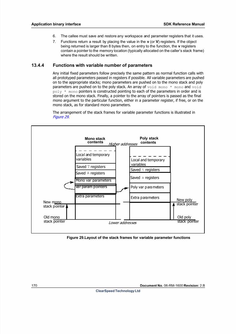
8/9/2019 SDK Reference Manual 3.1 Rev2.B
http://slidepdf.com/reader/full/sdk-reference-manual-31-rev2b 170/204

8/9/2019 SDK Reference Manual 3.1 Rev2.B
http://slidepdf.com/reader/full/sdk-reference-manual-31-rev2b 171/204
SDK Reference Manual Application binary interface
Document No. 06-RM-1600 Revision: 2.B 171
ClearSpeed Technology Ltd
An example of calling a Cn function follows:
#include <macro_includes.inc>#include <dprint_defs.h>
#define PENUMS 24:p4#define PENUMS_F 24:p4f#define TOT_PES 28:p4#define TOT_PES_F 28:p4f#define RESULT 32:p4f#define RESULT_D 32:p8f
.global my_function ;// External function that will be called
.section .text
main::.global main.type main, @function
st _poly_sp, 56:p8, 0;st _poly_sp, 8:p8, 8;st _poly_sp, 24:p4, 16 ; //save poly registers to be
used.st _poly_sp, 28:p4, 20 ;st _poly_sp, 32:p8, 24 ;
return.get 60:m4u;st _mono_sp, 60:m4u, 0;//save return address

8/9/2019 SDK Reference Manual 3.1 Rev2.B
http://slidepdf.com/reader/full/sdk-reference-manual-31-rev2b 172/204
Application binary interface SDK Reference Manual
172 Document No. 06-RM-1600 Revision: 2.B
ClearSpeed Technology Ltd
// Convert PE number to a number in range 0 to 1penum PENUMS; // get number of this PE
cast PENUMS_F, PENUMS; // convert tofloat
mov TOT_PES, _num_pes
cast TOT_PES_F, TOT_PES;// get total number of pe's infloat format
div RESULT, PENUMS_F, TOT_PES_F; //ratio
cast RESULT_D, RESULT;// sinp takes a double so castfloat into double
mov 8:p8f, RESULT_D ;// put parameter in correct
register
// Call sinp() function // add offsets to the stack frame pointers, to allocate new stackframes
add _mono_sp, _mono_sp, 16; // allocate new mono stackframe
add _poly_sp, _poly_sp, 32; // allocate new poly stackframe
j.sub my_function;
// Subtract offsets from stack frame pointers to free stack framesub _mono_sp, _mono_sp, 16;
sub _poly_sp, _poly_sp, 32;
mov 8:p8f, 0:p8f; // put return result in passingregister.
// Call print_result function// add offsets to the stack frame pointers, to allocate new stack
framesadd _poly_sp, _poly_sp, 32; // allocate new poly stack
frameadd _mono_sp, _mono_sp, 16; // allocate new mono stack frame
j.sub print_result;
// Subtract offsets from stack frame pointers to free stack frame
sub _mono_sp, _mono_sp, 16;sub _poly_sp, _poly_sp, 32;
mov 8:m4, 0 ; // return value of 0
ld 56:p8, _poly_sp, 0;ld 8:p8, _poly_sp, 8;//restore poly registersld 24:p4, _poly_sp, 16 ;ld 28:p4, _poly_sp, 20 ;ld 32:p8, _poly_sp, 24 ;
ld 60:m4u, _mono_sp, 0; // restore return address and jumpj 60:m4u ;

8/9/2019 SDK Reference Manual 3.1 Rev2.B
http://slidepdf.com/reader/full/sdk-reference-manual-31-rev2b 173/204
SDK Reference Manual Application binary interface
Document No. 06-RM-1600 Revision: 2.B 173
ClearSpeed Technology Ltd
print_result::.global print_result
mov 16:m4, _CN_LIBEXT_DPRINT_DEC_FORMAT |_CN_LIBEXT_DPRINT_FLOAT_TYPE ; // output decimal float.setpolytemp 56, 8set.varargs 8:p8f;// put parameter.setmonotemp 60, 4call.varargs dprint_poly;// call dprint
return
The Cn function that is called from the code is:
extern poly double my_function(poly double x) {return (3*x);}
13.4.5 Status and predicate bits
The status flags are not guaranteed to be preserved across a function call. However, the userpredicate state must be preserved. It is the responsibility of the callee to save the state if thepredicates are modified. For more information on how to save and restore the state, see [1]:CSX600 Instruction Set Reference Manual .
13.4.6 Enable state
Functions must preserve the entire state of the enable stack.The convention used by the compiler is that, on entry to a function that may change theenable state, the enable stack is saved at the start of the function and restored when thefunction exits.
By convention, all code should use up to five levels of enable state in a function before savingand restoring this nesting, giving an indefinite amount of enable state to the user. This leavestwo levels for assembler instructions.
Note that some macro instructions make use of the enable stack. This is documented in the[1]: CSX600 Instruction Set Reference Manual and must be taken into account when calcu-lating the enable stack usage. For more information on saving and restoring the enable state,see [1]: CSX600 Instruction Set Reference Manual for details.
13.5 Poly scratch memory
A small amount of poly memory, 128 bytes, is reserved as scratch memory for the PIO mem-ory transfer routines defined in the standard library. This memory is also reused by thedebugger for reading and writing poly registers.
The start address for this memory is defined by the global symbol_poly_io_queue_scratch_space .
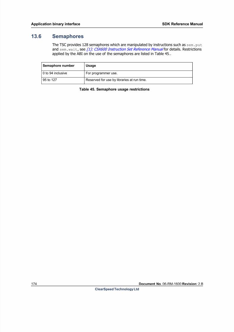
8/9/2019 SDK Reference Manual 3.1 Rev2.B
http://slidepdf.com/reader/full/sdk-reference-manual-31-rev2b 174/204
Application binary interface SDK Reference Manual
174 Document No. 06-RM-1600 Revision: 2.B
ClearSpeed Technology Ltd
13.6 Semaphores
The TSC provides 128 semaphores which are manipulated by instructions such as sem.put and sem.wait, see [1]: CSX600 Instruction Set Reference Manual for details. Restrictions
applied by the ABI on the use of the semaphores are listed in Table 45..
Semaphore number Usage
0 to 94 inclusive For programmer use.
95 to 127 Reserved for use by libraries at run time.
Table 45. Semaphore usage restrictions

8/9/2019 SDK Reference Manual 3.1 Rev2.B
http://slidepdf.com/reader/full/sdk-reference-manual-31-rev2b 175/204
SDK Reference Manual Application binary interface
Document No. 06-RM-1600 Revision: 2.B 175
ClearSpeed Technology Ltd
13.7 Endianness
Endianness defines the way that data is stored in memory, that is, the order of bytes in mem-ory for multi byte objects. This is illustrated in Figure 30 .
Byte 0
Increasingaddresses
Least Sig Byte
Most Sig Byte
Most Sig Byte
Least Sig Byte
Little Endian Big Endian
Byte n-1
Figure 30.Layout of 4 byte value in memory
Because it is designed to be integrated in a variety of embedded systems, the processor isimplemented as a bi-endian architecture; it can switch between big and little-endian.
In little-endian mode, the processor stores the least significant byte of a multibyte object atthe lowest memory address. In big-endian mode, the processor stores the least significantbyte of a multibyte object at the highest memory address.
These two ways of storing data in memory are illustrated for 2- and 4-byte objects in
Figure 31 .
lsb0
158msb
1
70lsb
0
70
1
158
2
2316
3
3124msb
msb: most significant bytelsb: least significant byte
byte
ms bit ls b it
Key
msb
0
158 lsb
1
70 msb 3124 2316 158 70 lsb
Increasing Addresses
0 1 2 3
Figure 31.Big and little endian values in memory
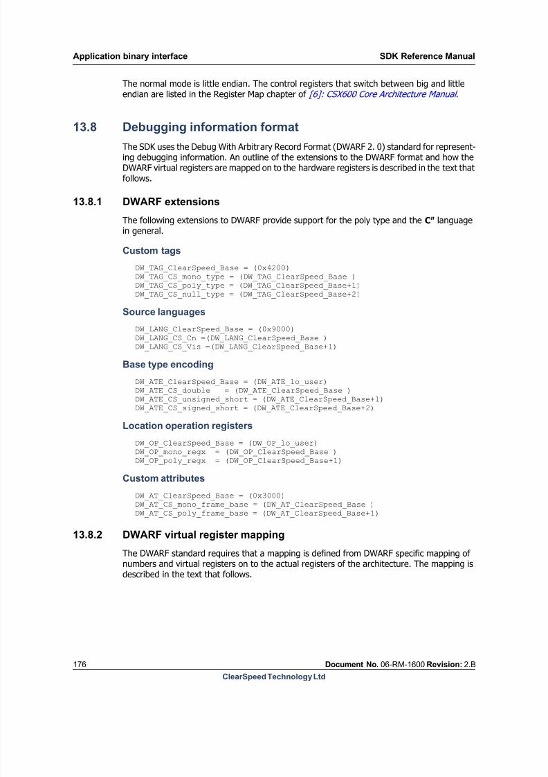
8/9/2019 SDK Reference Manual 3.1 Rev2.B
http://slidepdf.com/reader/full/sdk-reference-manual-31-rev2b 176/204
Application binary interface SDK Reference Manual
176 Document No. 06-RM-1600 Revision: 2.B
ClearSpeed Technology Ltd
The normal mode is little endian. The control registers that switch between big and littleendian are listed in the Register Map chapter of [6]: CSX600 Core Architecture Manual .
13.8 Debugging information formatThe SDK uses the Debug With Arbitrary Record Format (DWARF 2. 0) standard for represent-ing debugging information. An outline of the extensions to the DWARF format and how theDWARF virtual registers are mapped on to the hardware registers is described in the text thatfollows.
13.8.1 DWARF extensions
The following extensions to DWARF provide support for the poly type and the Cn languagein general.
Custom tags
DW_TAG_ClearSpeed_Base = (0x4200)
DW_TAG_CS_mono_type = (DW_TAG_ClearSpeed_Base )DW_TAG_CS_poly_type = (DW_TAG_ClearSpeed_Base+1)DW_TAG_CS_null_type = (DW_TAG_ClearSpeed_Base+2)
Source languages
DW_LANG_ClearSpeed_Base = (0x9000)
DW_LANG_CS_Cn =(DW_LANG_ClearSpeed_Base )DW_LANG_CS_Vis =(DW_LANG_ClearSpeed_Base+1)
Base type encoding
DW_ATE_ClearSpeed_Base = (DW_ATE_lo_user)
DW_ATE_CS_double = (DW_ATE_ClearSpeed_Base ) DW_ATE_CS_unsigned_short = (DW_ATE_ClearSpeed_Base+1)
DW_ATE_CS_signed_short = (DW_ATE_ClearSpeed_Base+2)
Location operation registers
DW_OP_ClearSpeed_Base = (DW_OP_lo_user)
DW_OP_mono_regx = (DW_OP_ClearSpeed_Base )DW_OP_poly_regx = (DW_OP_ClearSpeed_Base+1)
Custom attributes
DW_AT_ClearSpeed_Base = (0x3000)
DW_AT_CS_mono_frame_base = (DW_AT_ClearSpeed_Base )DW_AT_CS_poly_frame_base = (DW_AT_ClearSpeed_Base+1)
13.8.2 DWARF virtual register mapping
The DWARF standard requires that a mapping is defined from DWARF specific mapping ofnumbers and virtual registers on to the actual registers of the architecture. The mapping isdescribed in the text that follows.

8/9/2019 SDK Reference Manual 3.1 Rev2.B
http://slidepdf.com/reader/full/sdk-reference-manual-31-rev2b 177/204
SDK Reference Manual Application binary interface
Document No. 06-RM-1600 Revision: 2.B 177
ClearSpeed Technology Ltd
The mapping is split as follows:
DW_OP_reg0, DW_OP_reg1, . . . , DW_OP_reg31
The DW_OP_regn operations encode the names of up to 32 registers, numbered from
0 to 31, inclusive. The object address is in register n.
DW_OP_regx
The DW_OP_regx operation has a single unsigned LEB 128 literal operand that
encodes the name of a register.
One of the key concepts in the DWARF standard is to provide areas to compress commonlyused values because the debug information can be large. This is the idea behind the 32 reg-ister mappings described above. However, the processor has many registers, including thevirtual mapping of 2, 4, and 8 registers on to the actual 2 and 1-byte register files, so theuse of these 32 registers is fairly unimportant. Therefore, the thirty two 4-byte poly registersare mapped to these as follows:
DW_OP_reg0 -> 0:p4DW_OP_reg1 -> 4:p4
. . .DW_OP_reg31 -> 124:p4
The following defines a DW_OP_regx for each of base registers and for each of the virtualregisters, repeating the definition of 4-byte poly registers to keep everything orthogonal. Thefirst five registers represent the state that either the caller or callee must save if they wantto use these registers, as described in 13.3.3: Register model . Some of these are implicit reg-isters which are not given symbolic names, but must be represented explicitly in DWARF,thus describing what has really been saved and restored.
DW_OP_regx 0 -> CFA
DW_OP_regx 1 -> program counter (pc)
DW_OP_regx 2 -> predicatesDW_OP_regx 3 -> enable state (enable state)
DW_OP_regx 4 -> return rule
DW_OP_regx 5 -> return register (ret)
DW_OP_regx 6 -> not used
DW_OP_regx 7 -> not used
DW_OP_regx 8 -> not used
DW_OP_regx 9 -> not used
2-byte mono registers
DW_OP_regx 10 -> 0:m2
DW_OP_regx 11 -> 2:m2
. . .DW_OP_regx 41 -> 62:m2
4-byte mono registers
DW_OP_regx 42 -> 0:m4
DW_OP_regx 43 -> 4:m4
. . .DW_OP_regx 57 -> 60:m4
8-byte mono registers
DW_OP_regx 58 -> 0:m8
DW_OP_regx 59 -> 8:m8
. . .DW_OP_regx 65 -> 56:m8

8/9/2019 SDK Reference Manual 3.1 Rev2.B
http://slidepdf.com/reader/full/sdk-reference-manual-31-rev2b 178/204
Application binary interface SDK Reference Manual
178 Document No. 06-RM-1600 Revision: 2.B
ClearSpeed Technology Ltd
1-byte poly registers
DW_OP_regx 66 -> 0:p1
DW_OP_regx 67 -> 1:p1
. . .
DW_OP_regx 193 -> 127:p1
2-byte poly registers
DW_OP_regx 194 -> 0:p2
DW_OP_regx 195 -> 2:p2
. . .DW_OP_regx 257 -> 126:p2
4-byte poly registers
DW_OP_regx 258 -> 0:p4
DW_OP_regx 259 -> 4:p4
. . .DW_OP_regx 289 -> 124:p4
8-byte poly registers
DW_OP_regx 290 -> 0:p8
DW_OP_regx 291 -> 8:p8
. . .DW_OP_regx 305 -> 120:p8
16-byte poly registers
DW_OP_regx 306 -> 0:p16
DW_OP_regx 307 -> 16:p16
. . .DW_OP_regx 313 -> 112:p16
32-byte poly registers
DW_OP_regx 314 -> 0:p32
DW_OP_regx 315 -> 32:p32
. . .DW_OP_regx 317 -> 96:p32
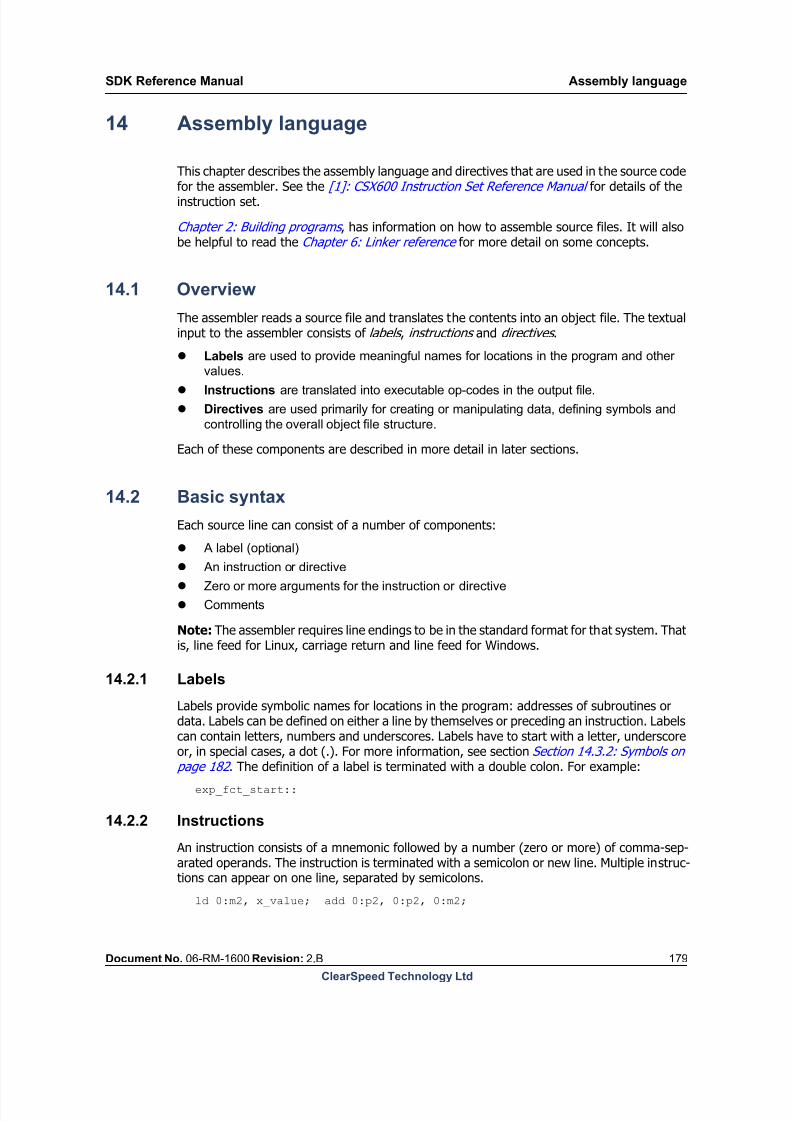
8/9/2019 SDK Reference Manual 3.1 Rev2.B
http://slidepdf.com/reader/full/sdk-reference-manual-31-rev2b 179/204
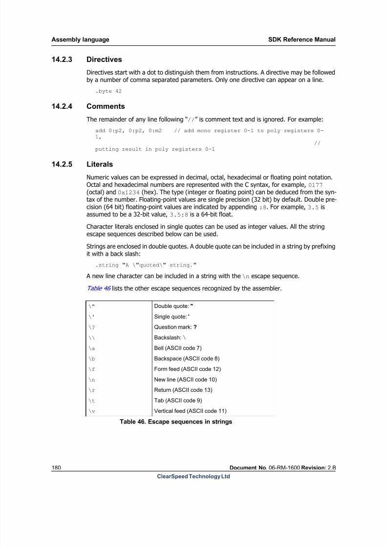
8/9/2019 SDK Reference Manual 3.1 Rev2.B
http://slidepdf.com/reader/full/sdk-reference-manual-31-rev2b 180/204
Assembly language SDK Reference Manual
180 Document No. 06-RM-1600 Revision: 2.B
ClearSpeed Technology Ltd
14.2.3 Directives
Directives start with a dot to distinguish them from instructions. A directive may be followedby a number of comma separated parameters. Only one directive can appear on a line.
.byte 42
14.2.4 Comments
The remainder of any line following “//” is comment text and is ignored. For example:
add 0:p2, 0:p2, 0:m2 // add mono register 0-1 to poly registers 0-1,
//putting result in poly registers 0-1
14.2.5 Literals
Numeric values can be expressed in decimal, octal, hexadecimal or floating point notation.
Octal and hexadecimal numbers are represented with the C syntax, for example, 0177 (octal) and 0x1234 (hex). The type (integer or floating point) can be deduced from the syn-tax of the number. Floating-point values are single precision (32 bit) by default. Double pre-cision (64 bit) floating-point values are indicated by appending :8. For example, 3.5 isassumed to be a 32-bit value, 3.5:8 is a 64-bit float.
Character literals enclosed in single quotes can be used as integer values. All the stringescape sequences described below can be used.
Strings are enclosed in double quotes. A double quote can be included in a string by prefixingit with a back slash:
.string "A \"quoted\" string."
A new line character can be included in a string with the \n escape sequence.
Table 46 lists the other escape sequences recognized by the assembler.
\" Double quote: "
\' Single quote: '
\? Question mark: ?
\\ Backslash: \
\a Bell (ASCII code 7)
\b Backspace (ASCII code 8)
\f Form feed (ASCII code 12)
\n New line (ASCII code 10)
\r Return (ASCII code 13)
\t Tab (ASCII code 9)
\v Vertical feed (ASCII code 11)
Table 46. Escape sequences in strings
8/9/2019 SDK Reference Manual 3.1 Rev2.B
http://slidepdf.com/reader/full/sdk-reference-manual-31-rev2b 181/204
SDK Reference Manual Assembly language
Document No. 06-RM-1600 Revision: 2.B 181
ClearSpeed Technology Ltd
14.3 Sections and symbols
As well as the instructions and data, the object file generated from the source contains infor-mation about sections and symbols .
14.3.1 Sections
The assembler organizes the data in an assembled program into named sections of relatedinformation – code, data, debug information, and so on. In the final stages of processing,these are transformed into an executable code image by the linker.
The standard sections are:
The assembler maintains a location counter for each section. This holds the next offset inthat section where information from the source file will be stored. The location counter willbe adjusted each time data or code is stored in a section and can also be manipulated explic-itly by directives such as .align. Each time the .section directive is used, the assembler
\0octal-digits Character with octal code octal-digits
\xhex-digits Character with hexadecimal code hex-digits
Table 46. Escape sequences in strings
.text stores the code corresponding to the instructions in the input file.
.poly.data contains initialized poly variables and other poly data.
.mono.data contains initialized mono variables and other mono data.
.poly.bss reserves storage for undefined poly data. On loading will be initialized to 0.
.mono.bss reserves storage for undefined mono data. On loading will be initialized to 0.

8/9/2019 SDK Reference Manual 3.1 Rev2.B
http://slidepdf.com/reader/full/sdk-reference-manual-31-rev2b 182/204
Assembly language SDK Reference Manual
182 Document No. 06-RM-1600 Revision: 2.B
ClearSpeed Technology Ltd
will append subsequent data or instructions to the newly selected section. This is illustratedin Figure 32 .
.section .text // select .text as
// the current section
mov 0:m2, 10; // write instructions
mov 2:m2, 0:m2; // to .text
.section .mono.data // switch output to
// .data section
_my_int:: // define symbol
.int 4 // allocate storage
// initialize to 4
.section .text // switch back to .text
// section
mov 0:p2, 10; // continue outputting
mov 2:p2, 0:p2; // code to .text
.text
.mono.data
mov 0:m2; 10
mov 2:m2; 0:m2
mov 0:p2; 10
mov 2:p2; 0:p2
0x00000004
_my_int
Symbol table
Figure 32.Textual input and memory organization
14.3.2 Symbols
Labels and named data objects (strings, integers, bytes, and so on) are referred to as sym-bols. The assembler maintains a relationship between the symbol name, its value, storagelocation (for data objects) and the section in which they were defined. Symbols can bedivided into the following categories:
Local. All symbols explicitly created in the input file are assumed to be local . Local
symbols can only be referenced in the source file where they are defined. It is not an
error if, at link time, multiple local symbols with the same name are encountered in
different files.
Global. Symbols can be made visible to other source files by declaring them as global .
Global symbols must have unique names not only in the context of the file in which theywere defined, but all the files constituting the final executable.
External. Any symbol that has been referenced in the input file, and for which the
definition has not been found is defined as external . The value of this symbol will not be
known until the object file is linked with another file that defines a value for the symbol.
Internal. Internal symbols are a special case of local symbol. They use a specific
syntax for their names: they must begin with .LL. Internal symbols are never placed in
the file’s symbol table and so are not visible to the debugger. Internal symbols can be
used for determining size of objects, for example, structures or functions, performing
local jumps, and so on.
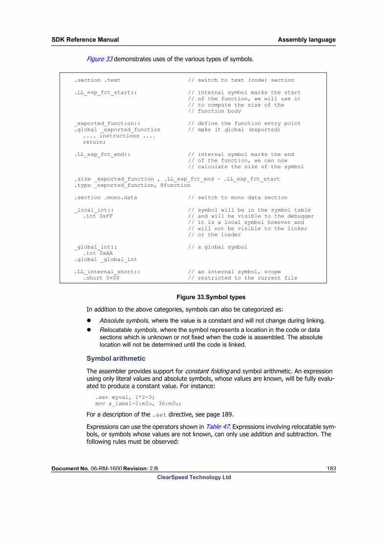
8/9/2019 SDK Reference Manual 3.1 Rev2.B
http://slidepdf.com/reader/full/sdk-reference-manual-31-rev2b 183/204

8/9/2019 SDK Reference Manual 3.1 Rev2.B
http://slidepdf.com/reader/full/sdk-reference-manual-31-rev2b 184/204
Assembly language SDK Reference Manual
184 Document No. 06-RM-1600 Revision: 2.B
ClearSpeed Technology Ltd
1. Two absolute(1) values can be added or subtracted, the result is an absolute value.
2. An absolute value can be added to or subtracted from a relocatable symbol, the result
is a relocatable symbol.
3. Two relocatable symbols can be subtracted, the result is an absolute value. In this
case, the two symbols must be defined in the same file so their relative values areknown when the file is assembled.
The operations are not commutative and the relocatable symbol must be the first operand.
14.4 Instructions
Instructions are made up of a mnemonic and zero or more operands. Instructions allow a
mixture of mono , poly and immediate operands. Some instructions are executed on manyprocessing elements in the poly execution unit, others only on the mono execution unit.Where an instruction is executed is usually determined by multiplicity of the operand.. Thisis fully explained in the [1]: CSX600 Instruction Set Reference Manual .
The assembler is a macro assembler. This means that instructions in the source file may beassembled into one or more instructions on the target architecture. Moreover, some instruc-tions may require temporary mono or poly registers for work space. Temporary registers arenot passed in as part of each instruction. Instead, assembler directives are used to reserve
1. Here ‘absolute’ refers to either an absolute symbol or a constant literal.
+ - * / %
unary plus
unary minus
multiplication
division
modulo
Highest precedence
+ -addition
subtraction
<< >>shift left
shift right
< <= >=
> == !=
less than
less than or equal
greater than or equal
greater than
equal to
not equal to
& bit-wise and
^ bit-wise xor
| bit-wise or
&& ||logical and
logical or Lowest precedence
Table 47. Operators and precedence

8/9/2019 SDK Reference Manual 3.1 Rev2.B
http://slidepdf.com/reader/full/sdk-reference-manual-31-rev2b 185/204
SDK Reference Manual Assembly language
Document No. 06-RM-1600 Revision: 2.B 185
ClearSpeed Technology Ltd
register space to use as work space (see the descriptions of the .setmonotemp and.setpolytemp directives on page 190).
14.4.1 Instruction mnemonics
Instruction mnemonics describe the operation to be performed. Instruction names are alpha-betic, with dots separating the fields of an instruction name. For example, a subset of thecompare instructions have the form cmp.cond , where the condition code, cond , is eq for
‘compare equal’, gt for ‘compare greater than’, and so on.
There is not a one-to-one mapping between mnemonics and machine instructions: theassembler uses the operand types to determine which op-code should be generated. Forexample, the add mnemonic can generate different instruction op-codes depending onwhether the operands are integer or floating point, mono or poly.
See the [1]: CSX600 Instruction Set Reference Manual for details of the instruction mnemon-ics.
14.4.2 Operands
Operands have the form value :specifiers , where the “:” and the specifiers are optional com-ponents. The value can be a numeric literal or a label. The value specifies a register or a literalvalue, depending on the specifier. The specifiers are four fields after the colon: domain , size ,type and vector size . The specifiers must appear in this order. Domain is either m, p or i formono, poly or immediate. Size is normally 1 to 8 (bytes). Type is u, s or f for unsigned inte-ger, signed integer or float respectively. The vector size is for specific instructions which takevector arguments. These indicate a contiguous grouping of vector size elements of width sizein the mono or poly register file. Square brackets are used to indicate the vector size.
Note that for some operations involving data movement the size field can be up to 64 bytes.
The operand structure is shown in Figure 34 .
0:p8f[2]
value (register address)
domain (poly) size (8 bytes) type (floating point)
vector size(optional)
Figure 34.An illustration of the fields for an instruction operand
The example above indicates two double-precision floating-point (8-byte) values in the polyregister file starting at location 0.
The value field may be any of the following:
numeric literal
label
absolute symbol
variable

8/9/2019 SDK Reference Manual 3.1 Rev2.B
http://slidepdf.com/reader/full/sdk-reference-manual-31-rev2b 186/204
Assembly language SDK Reference Manual
186 Document No. 06-RM-1600 Revision: 2.B
ClearSpeed Technology Ltd
The value field can be interpreted as either a register or an immediate, depending on thedomain specifier.
If the domain is mono or poly, then the value field is considered to be a register address.Note that this specifies a byte index into the register file of the appropriate domain. For
example, if there are 32 16-bit mono registers, the address will be in the range 0–63.
The default domain is immediate. If the width of an immediate or label is not specified, it isassumed to be 4 bytes.
It is possible to use arithmetic expressions to generate the value field for both registers andimmediates.
For example:
mov 0:m2, 10+23 // Moves 33 into 2-byte mono registers 0mov 10+2:m2, 1 // Moves 1 into 2-byte mono register 12
Specifiers may be omitted in some cases. The defaults are:
domain = immediate
type = unsigned for registers
width = 1 for registers
width = 4 for immediates.
However, explicitly qualifying all arguments can provide some extra error checking.
There are also some functions which can be used on operands to select the least significantor most significant bytes. These functions are .lsbytes and .msbytes. These are docu-mented under the description of macro instructions in Section : Operand functions on
page 196 . For example, .lsbytes(.LL_mylabel, 2) would return the two least signifi-cant bytes of the label .LL_mylabel.
The instruction set document defines any constraints on the use of the operands for eachinstruction.
Predefined operands
There are a number of predefined named operands which can be used where a regular oper-and would be used in an instruction. These are defined by the configuration file (seeChapter 1: SDK overview , for more information). Most of these are part of the ABI which isneeded to interact with compiled code (see Chapter 13: Application binary interface ).Table 48 lists the predefined operands.
Name Description Type(a)
_mono_sp Mono stack pointer R (m4u)
_poly_sp Poly stack pointer R (m2u)
_num_pes Number of poly processing elements (PEs) I
_poly_memory_size Size of memory (in bytes) in each PE I
_mono_temp_start Start address of mono temporary registers I
_mono_temp_size Size (in bytes) allocated for mono temporary registers I
Table 48. Predefined operands

8/9/2019 SDK Reference Manual 3.1 Rev2.B
http://slidepdf.com/reader/full/sdk-reference-manual-31-rev2b 187/204
SDK Reference Manual Assembly language
Document No. 06-RM-1600 Revision: 2.B 187
ClearSpeed Technology Ltd
The predefined operands may be either registers or immediate values. These are shown inthe table as R or I, respectively. For registers the appropriate specifiers are also shown. Someof the immediate operands are to be used as the addresses of registers. These should beused with specifiers, to define their domain, type and width.
Figure 35 shows some example instructions.
mov _mono_sp, 20 // Move 20 into mono_sp, defined as a registeradd _poly_ret_val:p1, 4:p1, 8:p1 // poly_ret_val is defined as an immediate value, so // add specifiers to turn it into a register
add 0:p2, 0:p2, 0:m2 // add mono register 0-1 to poly registers 0-1, // putting result in poly registers 0-1mul 4:m4, 0:m2, 23 // multiply mono register 0-1 by 23 (unsigned), // putting result in mono registers 4-7mul 4:p4s, 8:p2s, 12:p2u // multiply poly registers 8-9 by poly register 12 // (signed x unsigned)
Figure 35.Example instructions
Endianness and registers
In a little-endian configuration of the processor, the least significant byte of a 2-byte (orlarger) register, will be the lowest byte address. For example, if 0:m2 holds the number0x1234 then, for the little endian case, byte 0 (0:m1) contains 0x34 (the least significantbyte) and byte 1 (1:m1) contains 0x12 (the most significant byte).
Conversely, in a big endian system 0:m1 would contain 0x12 (the most significant byte) and1:m1 would contain 0x34.
_poly_temp_start Start address of poly temporary registers I
_poly_temp_size Size (in bytes) allocated for poly temporary registers I
_mono_ret_val Address of register used for mono return value from a function I
_mono_ret_val_size Size (in bytes) of register used for mono return value from a function I
_poly_ret_val Address of register used for poly return value from a function I
_poly_ret_val_size Size (in bytes) of register used for poly return value from a function I
_num_pio Number of channels of PIO I
_mono_stack_size Memory reserved for mono stack (in bytes) I
_poly_stack_size Memory reserved for poly stack (in bytes) I
_sem_print
_sem_print_ex
_reserved_sem_bank_0
_reserved_sem_bank_1
_reserved_sem_bank_2
_reserved_sem_bank_3
Reserved semaphores I
a. R = register I = immediate
Name Description Type(a)
Table 48. Predefined operands
8/9/2019 SDK Reference Manual 3.1 Rev2.B
http://slidepdf.com/reader/full/sdk-reference-manual-31-rev2b 188/204
Assembly language SDK Reference Manual
188 Document No. 06-RM-1600 Revision: 2.B
ClearSpeed Technology Ltd
14.5 Directives
Directives provide means of emitting data, setting or changing symbol parameters and cre-ating the structure of an executable file. All directive names start with dot.
In the following descriptions, italics indicate parameters to the directives and squarebrackets, [], indicate optional components, * indicates parameters that can be repeated.
.alias alias { instruction [, instruction] }
See the description of macro definitions in Section 14.6.1: Matching macros against instruc- tions on page 193 .
.align alignment [, value]
Advances the current value of the location counter in the current section to the requiredalignment in bytes. For example, .align 8 advances the location counter until it is a mul-tiple of 8. The second expression (also absolute) is the value to be stored in the paddingbytes. If the value is omitted, the padding bytes are zero.
Data should be naturally aligned. It is advisable to specify a .align directive before emittingany data with an increased data width than was previously specified.
.ascii "text" [, "text"]*
Emits a string constant into the current section.
.asciz "text" [, "text"]*
.string "text" [, "text"]*
Emits a string constant into the current section. A null, ‘\0’, character is automaticallyappended to terminate the string.
.byte const [, const]*
.double const [, const]* .float const [, const]*
.int const [, const]*
.short const [, const]*
Emit a numeric constant into the current section. The parameter expression can be an abso-lute expression as defined on page 183. The expression for .byte, .int, and .short has tobe an integer value. These directives do not do any padding to maintain alignment. The bytesequence representing the value will be put in the object file at the current location. Use the.align directive to maintain alignment if necessary.
.fill repeat, size, value
This directive emits repeat copies of size bytes taken from the value. The parameters
repeat, size and value are absolute expressions. repeat may be zero or more. size may be zero or more but if it is more than eight, then it is truncated to eight – behavior com-patible with other assemblers. The contents of the value that .fill emits is taken from aneight-byte number. The highest order four bytes are zero. The lowest order four bytes arethe bytes in value rendered in the byte order of the target that the code is generated for.The fill bytes are taken from the lowest order size bytes of this number.
.global name
This directive makes the symbol name global, that is, it is stored in the symbol table and isvisible to the linker and other object files. If the symbol is defined in the current file, its valueis made available to other object files that are linked with the object file. Global symbols must
8/9/2019 SDK Reference Manual 3.1 Rev2.B
http://slidepdf.com/reader/full/sdk-reference-manual-31-rev2b 189/204
SDK Reference Manual Assembly language
Document No. 06-RM-1600 Revision: 2.B 189
ClearSpeed Technology Ltd
be defined in one of the object files that are linked to create an executable file. Global sym-bols cannot be defined in multiple files.
.pragma pragma_name state
This directive switches pragma_name to be on or off. state is either on or off. The fol-lowing pragma_names are available for use:
alignment_unknown
This directive, if set to on, forces the instruction set to emit 1-byte load stores. This is
only advised when absolutely necessary.
DEBUG_ON
This directive, if set to on, informs the instruction set that it is being run in debug mode.
That is, it makes sure that the vector instructions flush after each instruction.
no_pipeline_nops
This directive, if set to on, will stop mass inserting nops into the instruction stream and
should only be used when you know that there are no hazards present.
suppress_vector_flush
This directive, if set to on, stops the instruction set automatically flushing the vector
pipelines.
.section name [, parameter ]*
This directive creates a new section or sets the named section as the current section. All fur-ther directives and instructions will append data to this section until another .section directive changes the current section.
Section names can consist only of alphanumeric characters, underscore and the dot. Use ofspaces is not allowed. It is traditional to start section names with a dot. Sections are alsodescribed by a number of parameters that determine their alignment constraints, storage
requirements, and so on. The object file format conforms to the ELF file format specification[9]: Executable and Linkable Format (ELF) and the standard section names defined there arerecognized.
The names of data sections are prefixed with .mono and .poly to denote their multiplicity.Such compound section names, for example .poly.bss, are automatically and correctlyidentified by the assembler as, in this case, .bss type.
When defining custom sections, where default values are not accessible, you need to specifysection parameters directly, in the optional parameter field of the directive, with a commaseparated list of parameters. The allowed parameters are: @write, @alloc and@progbits. The meaning of the parameters is defined in the ELF standard.
.set symbol, value
Creates, or updates, the value of an existing absolute symbol. Values of absolute symbolscan be set multiple times. The most recently assigned value is used when the symbol is ref-erenced.
The .set directive can also be used to create symbols representing operands. For instance:
.set temp_op, 32:m4u;
When these labels are subsequently used, you can override the specifiers. For instance:
mov temp_op:m2u, 36:m2u;

8/9/2019 SDK Reference Manual 3.1 Rev2.B
http://slidepdf.com/reader/full/sdk-reference-manual-31-rev2b 190/204
Assembly language SDK Reference Manual
190 Document No. 06-RM-1600 Revision: 2.B
ClearSpeed Technology Ltd
Note: The predefined operands described on page 186 can also be overridden in this way.
.setmonotemp [.perm] startreg , regsize
.setpolytemp [.perm] startreg , regsize
Specifies which mono and poly registers are used as temporary storage in the followinginstruction. The startreg parameter specifies the start address (as a byte offset) in theregister file. The regsize parameter defines the number of bytes to be reserved as tempo-raries. The instruction set documentation defines the number of temporary registers requiredby each predefined macro provided by ClearSpeed.
Normally, the temporary registers are only available for one instruction following the direc-tive. Each macro instruction which requires temporary registers should be preceded by adirective to allocate the appropriate number of registers. The following example sets the topfour bytes of the mono register file as temporaries for the following floating point add:
.setmonotemp 60, 4add 8:m4f, 8:m4f, 3.141
Although it is less efficient in register use, it is possible to use the optional .perm argumentto make permanent allocations of temporary registers. Consider, for example:
.section .text
.setpolytemp .perm 60, 4
.setmonotemp .perm 60, 4
This allocates four bytes from register 60 in the mono and poly register files for use as tem-porary registers by all following macros. The contents of these registers will not be preservedacross any macro instructions that use temporaries. It is your responsibility to ensure thatthese registers do not contain any data.
.size symbol, size
Changes the size of the symbol. If this directive appears prior to the symbol being created
then a symbol with the given name and with all properties set to default values, will be con-structed.
.type symbol, type
Sets the type of the symbol. The possible type values are: @object and @function. Thisdirective can appear anywhere in the source. The logic for creating symbols follows that ofthe .size directive.
14.5.1 CFI directives
Each time a program performs a function call, information about the call is generated. Thatinformation includes the location of the call in the program, the arguments of the call, and
the local variables of the function being called. The data is saved in two regions of memory(call stacks), one for mono state and the other for poly, as described in Chapter 13: Applica- tion binary interface . A debugger needs to be able to generate a stack trace from the currentprogram counter and to look at values from anywhere in the chain. Information about reg-isters saved in the stack are recorded using the DWARF debugging information format.
The DWARF 2.0 standard defines the section .debug_frame that is used to store the CFIinformation.

8/9/2019 SDK Reference Manual 3.1 Rev2.B
http://slidepdf.com/reader/full/sdk-reference-manual-31-rev2b 191/204
SDK Reference Manual Assembly language
Document No. 06-RM-1600 Revision: 2.B 191
ClearSpeed Technology Ltd
Entries are of two forms:
A Common Information Entry (CIE) holds information that is shared among many
Frame Descriptors and includes the following information:
code_alignment_factor
data_alignment_factor
These are used to multiply address for code and data respectively. For the processor,
these values are set to 16 and 1.
return_address_register
A constant that indicates which column in the rule table represents the return address
of the function.
A Frame Description Entry (FDE) contains at least the following fields:
CIE_pointer
This is an offset from the start of the .debug_frame section to a particular CIE.
initial_location
An addressing-unit sized constant indicating the first program address associated withthis entry.
Note: The program addresses are always mono so it does not need to have two types
of FDE.
CFI instructions
A sequence of DWARF CFI instructions describe the movement of registers. This sequence isthe actual heart of the DWARF CFI and describes the movement of registers to and from themono and poly stack and between themselves.
Section 13.8: Debugging information format on page 176 defines a mapping betweenDWARF virtual registers and the actual hardware registers of the processor that are exposedto you and captured by the ABI.
CFI directives
This section defines the CFI directives which are supported by the assembler and may beused directly by the assembler programmer.
.cfi_startprologue
This directive can be inserted at the start of each function. It tells the assembler to emit initialCFI instructions for the function.
.cfi_endepilogue
This directive can be inserted at the end of each function. It tells the assembler to emit theappropriate structures (CIE, FDE) and relocations for the CFI generated after a call to.cfi_startprologue.
.cfi_def_mono_cfa reg ,imm
This directive can be used to set a rule for computing the mono CFA from this addressonwards, until the CFA is defined by another directive. The directive changes the rule for cal-culating the CFA to use register reg and offset imm.

8/9/2019 SDK Reference Manual 3.1 Rev2.B
http://slidepdf.com/reader/full/sdk-reference-manual-31-rev2b 192/204
Assembly language SDK Reference Manual
192 Document No. 06-RM-1600 Revision: 2.B
ClearSpeed Technology Ltd
.cfi_def_mono_cfa_register reg
This directive changes the rule for calculating the mono CFA to use register reg . The offsetremains the same.
.cfi_def_mono_cfa_offset imm This directive changes the rule for calculating the mono CFA to use offset imm. The registerremains the same.
.cfi_adjust_mono_cfa_offset imm
Similar to the previous directive but imm is a relative value that will be added to current offsetinstead of an absolute value as in .cfi_def_mono_cfa_offset .
.cfi_def_poly_cfa reg ,imm
This directive can be used to set a rule for computing the poly CFA from this addressonwards, until the CFA is defined by another directive. The directive changes the rule for cal-culating the CFA to use register reg and offset imm.
.cfi_def_poly_cfa_register reg
This directive changes the rule for calculating the poly CFA to use the register reg . The offsetremains the same.
.cfi_def_poly_cfa_offset imm
This directive changes the rule for calculating the poly CFA to use the offset imm. The registerremains the same.
.cfi_adjust_poly_cfa_offset imm
Like the previous one but imm is a relative value that will be added to the current offsetinstead of an absolute value as in .cfi_def_poly_cfa_offset .
.cfi_offset reg ,imm
The final directive is a single rule for both poly and mono and should be used to generate arule saying that the register reg is saved at offset imm from the particular CFA.
.cfi_retsave imm
This directive can be used to generate a rule saying that the link register (see Chapter 13: Application binary interface ) is saved at offset imm from the particular CFA.
.cfi_def_restore reg
This directive can be used to generate a rule saying that reg has been restored and the lastsave rule, for reg, can be discarded.
14.6 Macros
A macro allows a mapping from a single macro instruction name onto a sequence of instruc-tions. Macros can be defined at any point in the assembly file and then used within the textsections. The assembler provides a sophisticated mechanism for macros which allows onefrom a number of different macros to be selected using not only the name but also by match-ing the number and types of the operands. A single macro can match a wide variety of oper-ands. For example, it is possible to define an add macro which will match both mono and
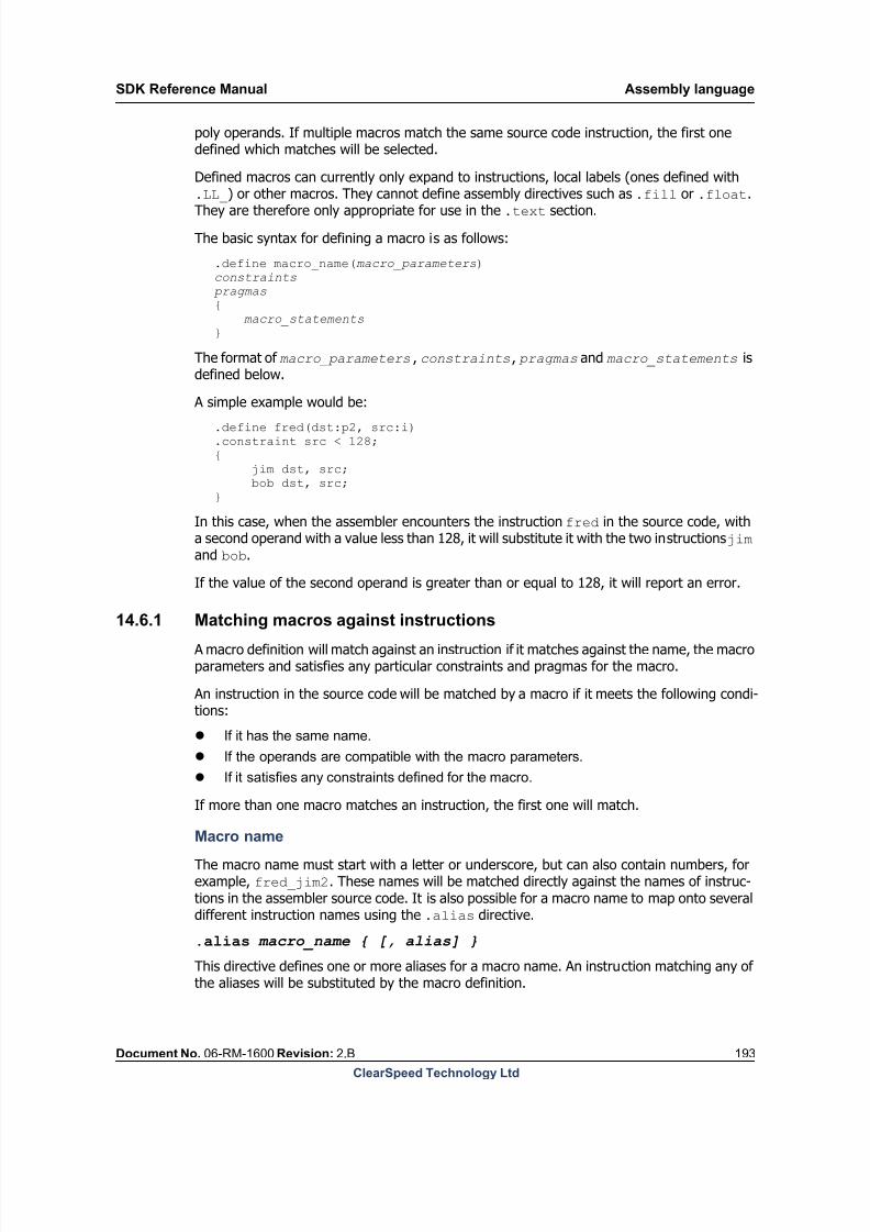
8/9/2019 SDK Reference Manual 3.1 Rev2.B
http://slidepdf.com/reader/full/sdk-reference-manual-31-rev2b 193/204
SDK Reference Manual Assembly language
Document No. 06-RM-1600 Revision: 2.B 193
ClearSpeed Technology Ltd
poly operands. If multiple macros match the same source code instruction, the first onedefined which matches will be selected.
Defined macros can currently only expand to instructions, local labels (ones defined with.LL_) or other macros. They cannot define assembly directives such as .fill or .float.
They are therefore only appropriate for use in the .text section.
The basic syntax for defining a macro is as follows:
.define macro_name(macro_parameters)constraints
pragmas{ macro_statements}
The format of macro_parameters, constraints, pragmas and macro_statements isdefined below.
A simple example would be:
.define fred(dst:p2, src:i)
.constraint src < 128;{ jim dst, src; bob dst, src;}
In this case, when the assembler encounters the instruction fred in the source code, witha second operand with a value less than 128, it will substitute it with the two instructions jim and bob.
If the value of the second operand is greater than or equal to 128, it will report an error.
14.6.1 Matching macros against instructions
A macro definition will match against an instruction if it matches against the name, the macroparameters and satisfies any particular constraints and pragmas for the macro.
An instruction in the source code will be matched by a macro if it meets the following condi-tions:
If it has the same name.
If the operands are compatible with the macro parameters.
If it satisfies any constraints defined for the macro.
If more than one macro matches an instruction, the first one will match.
Macro name
The macro name must start with a letter or underscore, but can also contain numbers, forexample, fred_jim2. These names will be matched directly against the names of instruc-tions in the assembler source code. It is also possible for a macro name to map onto severaldifferent instruction names using the .alias directive.
.alias macro_name { [, alias] }
This directive defines one or more aliases for a macro name. An instruction matching any ofthe aliases will be substituted by the macro definition.

8/9/2019 SDK Reference Manual 3.1 Rev2.B
http://slidepdf.com/reader/full/sdk-reference-manual-31-rev2b 194/204
Assembly language SDK Reference Manual
194 Document No. 06-RM-1600 Revision: 2.B
ClearSpeed Technology Ltd
For example:
.alias ld_st { load, store }
.define ld_st { ... body of macro definition
} Any occurrence of the instruction names load or store in the assembly source will bematched by the macro ld_st and replaced with the macro definition.
Macro parameters
A macro can have zero or more comma-separated macro parameters. Each of these param-eters will be matched against each of the operands of an instruction, in order. Every param-eter must match an operand for an instruction to match the macro. The number of parame-ters in the macro and the number of operands in the instruction must be the same.
A parameter can define specifiers for an operand, for example domain or width, which arematched against the source operands. Any specifier which is not defined is ‘wildcarded’ and
will match operands with any value for that specifier. For example, if the domain is notdefined, then an operand of any domain could match (provided that the other specifiersmatch). For domain and type, multiple specifiers can be defined to match either mono orpoly, or both unsigned and signed.
The vector size is assumed to be one but it can use : [ ] to wildcard.
Parameter syntax is similar to that for instruction operands, except that a name is used inplace of the value part and specifiers can be omitted or used multiple times. For example,dst:mp4us would match any operand which is either mono or poly, width 4 and is eitherunsigned or signed. For this example, both 32:p4s or 40:m4u would match but 36 (animmediate), 32:m4f (a float) or 40:p2s (width 2) would not. Note that the (otherwiserarely used) i specifier is used to match an immediate, for example dst:i. In addition to
these standard domains, l can be used to match a label, for example dst:l. If no specifiersare used to define a match, the ‘:’ should be omitted.
Although most parameters will be named and match any value, it is possible to use a fixedvalue instead of a name to limit matching to a particular operand, for example,lsl(dst:p4u, src0:p4u, 1) would match instruction lsl with four-byte unsigned polyoperands for dst and src0, but only the immediate value 1 for the final parameter.
The named parameters can be referenced by macro statements in the body of the macro orby constraint directives. The values of parameters can also be modified in the macro body.
Macro constraints
Constraints provide a way of further limiting which instructions a macro will match. This isdone by defining an expression which must be nonzero for the macro to match. This expres-sion can reference macro parameters or global symbols defined by a .set directive. Macroexpressions are described in more detailed below but, for example, comparative operatorssuch as < produce a nonzero result if they are true. Examples of constraint expressions are:
.constraint macro_expression;src1 < 50 or .width(src0) == 2.
Multiple constraints can be defined and an instruction must match all of them to match themacro.

8/9/2019 SDK Reference Manual 3.1 Rev2.B
http://slidepdf.com/reader/full/sdk-reference-manual-31-rev2b 195/204
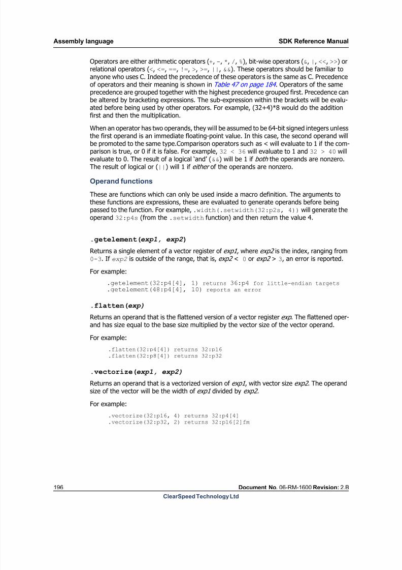
8/9/2019 SDK Reference Manual 3.1 Rev2.B
http://slidepdf.com/reader/full/sdk-reference-manual-31-rev2b 196/204
Assembly language SDK Reference Manual
196 Document No. 06-RM-1600 Revision: 2.B
ClearSpeed Technology Ltd
Operators are either arithmetic operators (+, -, *, /, %), bit-wise operators (&, |, <<, >>) orrelational operators (<, <=, ==, !=, >, >=, ||, &&). These operators should be familiar toanyone who uses C. Indeed the precedence of these operators is the same as C. Precedenceof operators and their meaning is shown in Table 47 on page 184 . Operators of the same
precedence are grouped together with the highest precedence grouped first. Precedence canbe altered by bracketing expressions. The sub-expression within the brackets will be evalu-ated before being used by other operators. For example, (32+4)*8 would do the additionfirst and then the multiplication.
When an operator has two operands, they will be assumed to be 64-bit signed integers unlessthe first operand is an immediate floating-point value. In this case, the second operand willbe promoted to the same type.Comparison operators such as < will evaluate to 1 if the com-parison is true, or 0 if it is false. For example, 32 < 36 will evaluate to 1 and 32 > 40 willevaluate to 0. The result of a logical ‘and’ (&&) will be 1 if both the operands are nonzero.The result of logical or (||) will 1 if either of the operands are nonzero.
Operand functions
These are functions which can only be used inside a macro definition. The arguments tothese functions are expressions, these are evaluated to generate operands before beingpassed to the function. For example, .width(.setwidth(32:p2s, 4)) will generate theoperand 32:p4s (from the .setwidth function) and then return the value 4.
.getelement(exp1, exp2 )
Returns a single element of a vector register of exp1 , where exp2 is the index, ranging from0-3. If exp2 is outside of the range, that is, exp2 < 0 or exp2 > 3, an error is reported.
For example:
.getelement(32:p4[4], 1) returns 36:p4 for little-endian targets
.getelement(48:p4[4], 10) reports an error
.flatten(exp)
Returns an operand that is the flattened version of a vector register exp . The flattened oper-and has size equal to the base size multiplied by the vector size of the vector operand.
For example:
.flatten(32:p4[4]) returns 32:p16
.flatten(32:p8[4]) returns 32:p32
.vectorize(exp1, exp2)
Returns an operand that is a vectorized version of exp1 , with vector size exp2 . The operandsize of the vector will be the width of exp1 divided by exp2.
For example:
.vectorize(32:p16, 4) returns 32:p4[4]
.vectorize(32:p32, 2) returns 32:p16[2]fm
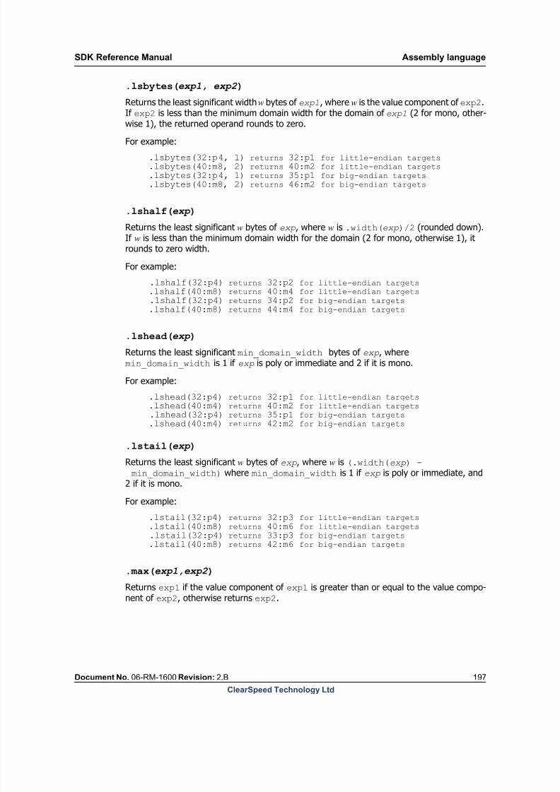
8/9/2019 SDK Reference Manual 3.1 Rev2.B
http://slidepdf.com/reader/full/sdk-reference-manual-31-rev2b 197/204
SDK Reference Manual Assembly language
Document No. 06-RM-1600 Revision: 2.B 197
ClearSpeed Technology Ltd
.lsbytes(exp1, exp2 )
Returns the least significant width w bytes of exp1, where w is the value component of exp2.If exp2 is less than the minimum domain width for the domain of exp1 (2 for mono, other-wise 1), the returned operand rounds to zero.
For example:
.lsbytes(32:p4, 1) returns 32:p1 for little-endian targets
.lsbytes(40:m8, 2) returns 40:m2 for little-endian targets .lsbytes(32:p4, 1) returns 35:p1 for big-endian targets
.lsbytes(40:m8, 2) returns 46:m2 for big-endian targets
.lshalf(exp )
Returns the least significant w bytes of exp, where w is .width(exp)/2 (rounded down).If w is less than the minimum domain width for the domain (2 for mono, otherwise 1), itrounds to zero width.
For example:
.lshalf(32:p4) returns 32:p2 for little-endian targets
.lshalf(40:m8) returns 40:m4 for little-endian targets .lshalf(32:p4) returns 34:p2 for big-endian targets
.lshalf(40:m8) returns 44:m4 for big-endian targets
.lshead(exp )
Returns the least significant min_domain_width bytes of exp, wheremin_domain_width is 1 if exp is poly or immediate and 2 if it is mono.
For example:
.lshead(32:p4) returns 32:p1 for little-endian targets .lshead(40:m4) returns 40:m2 for little-endian targets
.lshead(32:p4) returns 35:p1 for big-endian targets
.lshead(40:m4) returns 42:m2 for big-endian targets
.lstail(exp )
Returns the least significant w bytes of exp, where w is (.width(exp) - min_domain_width) where min_domain_width is 1 if exp is poly or immediate, and2 if it is mono.
For example:
.lstail(32:p4) returns 32:p3 for little-endian targets
.lstail(40:m8) returns 40:m6 for little-endian targets .lstail(32:p4) returns 33:p3 for big-endian targets
.lstail(40:m8) returns 42:m6 for big-endian targets
.max(exp1,exp2 )
Returns exp1 if the value component of exp1 is greater than or equal to the value compo-nent of exp2, otherwise returns exp2.

8/9/2019 SDK Reference Manual 3.1 Rev2.B
http://slidepdf.com/reader/full/sdk-reference-manual-31-rev2b 198/204
Assembly language SDK Reference Manual
198 Document No. 06-RM-1600 Revision: 2.B
ClearSpeed Technology Ltd
.min(exp1, exp2 )
Returns exp1 if the value component of exp1 is less than or equal to the value componentof exp2, otherwise returns exp2.
.msbytes(exp1, exp2 )
Returns the most significant width w bytes of exp1, where w is the value component of exp2.If exp2 is less than the minimum domain width for that domain (2 for mono, otherwise 1),the returned operand rounds to zero width.
For example:
.msbytes(32:p4, 1) returns 35:p1 for little-endian targets
.msbytes(40:m8, 2) returns 46:m2 for little-endian targets .msbytes(32:p4, 1) returns 32:p1 for big-endian targets
.msbytes(40:m8, 2) returns 40:m2 for big-endian targets
.mshalf(exp )
Returns the most significant width w bytes of exp, where w is the total width of exp /2(rounded down). If w is less than the minimum domain width for that domain (2 for mono,otherwise 1), it rounds to zero width.
For example:
.mshalf(32:p4) returns 34:p2 for little-endian targets
.mshalf(40:m8) returns 44:m4 for little-endian targets .mshalf(32:p4) returns 32:p2 for big-endian targets
.mshalf(40:m8) returns 40:m4 for big-endian targets
.mshead(exp )Returns the most significant min_domain_width bytes of exp, where min_domain_width is 1 if it is poly or immediate and 2 if is mono.
For example:
.mshead (32:p4) returns 35:p1 for little-endian targets
.mshead(40:m4) returns 42:m2 for little-endian targets .mshead (32:p4) returns 32:p1 for big-endian targets
.mshead(40:m4) returns 40:m2 for big-endian targets
.mstail(exp )
Returns the most significant width w bytes of exp, where w is the total width of exp -min_domain_width. min_domain_width is 1 if it is poly or immediate and 2 if is mono.
For example:
.mstail(32:p4) returns 33:p3 for little-endian targets
.mstail(40:m8) returns 42:m6 for little-endian targets .mstail(32:p4) returns 32:p3 for big-endian targets
.mstail(40:m8) returns 40:m6 for big-endian targets
.overlap(exp1, exp2 )
Returns 1 if exp1 and exp2 are both mono or both poly and the operands overlap.

8/9/2019 SDK Reference Manual 3.1 Rev2.B
http://slidepdf.com/reader/full/sdk-reference-manual-31-rev2b 199/204
SDK Reference Manual Assembly language
Document No. 06-RM-1600 Revision: 2.B 199
ClearSpeed Technology Ltd
For example:
.overlap(32:p4, 34:p4) returns 1
.overlap (32:p4, 40:p4) returns 0
.overlap (32:p4, 32:m4) returns 0
.setfloat(exp )
Returns an operand which is the same as exp, but with type float.
For example:
.setfloat(32:p4s) returns 32:p4f.
.setimmediate(exp )
Returns an operand which is the same as exp, but with domain immediate.
For example:
.setimmediate(32:p4s) returns 32.
.setmono(exp )
Returns an operand which is the same as exp, but with domain mono.
For example:
.setmono(32:p4s) returns 32:m4s.
.setpoly(exp )
Returns an operand which is the same asexp
, but with domain poly.
For example:
.setpoly(32:m4s) returns 32:p4s.
.setsigned(exp )
Returns an operand which is the same as exp, but with type signed.
For example:
.setsigned(32:p2u) returns 32:p2s.
.setunsigned(exp )Returns an operand which is the same as exp, but with type unsigned.
For example:
.setunsigned(32:p2s) returns 32:p2u.
.setwidth(exp1, exp2 )
Returns an operand which is the same as exp1, but with width specified by exp2.
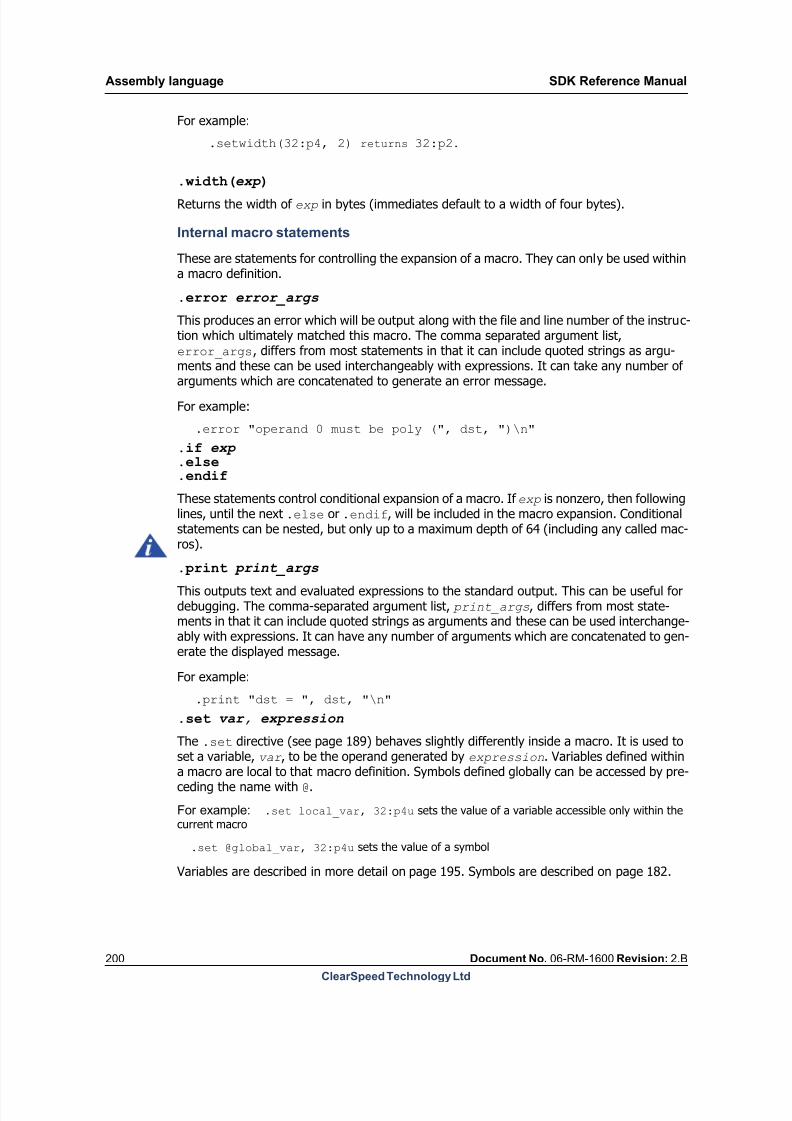
8/9/2019 SDK Reference Manual 3.1 Rev2.B
http://slidepdf.com/reader/full/sdk-reference-manual-31-rev2b 200/204
Assembly language SDK Reference Manual
200 Document No. 06-RM-1600 Revision: 2.B
ClearSpeed Technology Ltd
For example:
.setwidth(32:p4, 2) returns 32:p2.
.width(exp )Returns the width of exp in bytes (immediates default to a width of four bytes).
Internal macro statements
These are statements for controlling the expansion of a macro. They can only be used withina macro definition.
.error error_args
This produces an error which will be output along with the file and line number of the instruc-tion which ultimately matched this macro. The comma separated argument list,error_args, differs from most statements in that it can include quoted strings as argu-ments and these can be used interchangeably with expressions. It can take any number ofarguments which are concatenated to generate an error message.
For example:
.error "operand 0 must be poly (", dst, ")\n"
.if exp
.else
.endif
These statements control conditional expansion of a macro. If exp is nonzero, then followinglines, until the next .else or .endif, will be included in the macro expansion. Conditional statements can be nested, but only up to a maximum depth of 64 (including any called mac-ros).
.print print_args
This outputs text and evaluated expressions to the standard output. This can be useful fordebugging. The comma-separated argument list, print_args, differs from most state-ments in that it can include quoted strings as arguments and these can be used interchange-ably with expressions. It can have any number of arguments which are concatenated to gen-erate the displayed message.
For example:
.print "dst = ", dst, "\n"
.set var, expression
The .set directive (see page 189) behaves slightly differently inside a macro. It is used toset a variable, var , to be the operand generated by expression. Variables defined withina macro are local to that macro definition. Symbols defined globally can be accessed by pre-ceding the name with @.
For example: .set local_var, 32:p4u sets the value of a variable accessible only within thecurrent macro
.set @global_var, 32:p4u sets the value of a symbol
Variables are described in more detail on page 195. Symbols are described on page 182.
8/9/2019 SDK Reference Manual 3.1 Rev2.B
http://slidepdf.com/reader/full/sdk-reference-manual-31-rev2b 201/204
SDK Reference Manual Assembly language
Document No. 06-RM-1600 Revision: 2.B 201
ClearSpeed Technology Ltd
.temp [.align] var, expression
This creates a variable, var , with type based on the value expression. That is, var willhave the same width, domain, and type as expression. Before a macro using .temp iscalled, you need to set up sufficient temporary storage space in the mono or poly registers
for all the variables allocated by .temp directives. The directives used to allocate temporarystorage (.setmonotemp and .setpolytemp) are described on page 190.
If the variable needs to be aligned, the keyword .align should appear after .temp. Forexample, .temp .align t, 32:m4u will cause the variable to be aligned to its width.
14.6.3 Standard header files
There are a number of header files which define the standard macro instructions. To simplifyusing these, a file called macro_includes.inc is provided to include all the macro defini-tion files. This can be included in an assembler source file with the line:
#include <macro_includes.inc>
14.7 Instruction set extension library
The poly instructions for the CSX processor are implemented in microcode. To make effectiveuse of the available microcode a limited number of instructions are included in the baseinstruction set. Some less frequently used and application specific instructions are availablein an instruction set extension library.
The instructions described in the “complex instructions” section of the Instruction Set Refer- ence Manual and a number of more complex “swazzle” instructions have been moved to thenew extension library. If you use these instructions in your program, you will need to do thefollowing:
1. Add a call to the function __cn_extension_ucode() to your program to initialize the
instruction set extension library. This must be done before using any of the instructions
in this set.
2. When compiling your program, use the command line option with cscn:--use-add-ucode cn_ucode_extension
This informs the assembler and linker about the new instructions in the library.
See the [1]: CSX600 Instruction Set Reference Manual for information on the additionalinstructions included in this library.
8/9/2019 SDK Reference Manual 3.1 Rev2.B
http://slidepdf.com/reader/full/sdk-reference-manual-31-rev2b 202/204
Bibliography SDK Reference Manual
202 Document No. 06-RM-1600 Revision: 2.B
ClearSpeed Technology Ltd
15 Bibliography
[1] CSX600 Instruction Set Reference Manual
Document Number: 06-RM-1137ClearSpeed Technology
[2] The C n Standard Library Reference Manual
Document Number: 06-RM-1139ClearSpeed Technology
[3] SDK Introductory Programming Manual
Document Number: 06-UG-1117ClearSpeed Technology
[4] CSX600 Runtime Software User Guide
Document Number: 06-UG-1345ClearSpeed Technology
[5] ClearSpeed Visual Profiler User Guide
Document Number: 06-UG-1454ClearSpeed Technology
[6] CSX600 Core Architecture Manual
White Paper 06-RM-1304ClearSpeed Technology
[7] ClearSpeed CSX600 Hardware Programming Manual
Document Number: 06-RM-1305
ClearSpeed Technology[8] The C Programming Language
Brian W. Kernighan & Dennis M. RitchieISBN: 0131103628Prentice Hall, 1988
[9] Executable and Linkable Format (ELF)
Portable Formats Specification, Version 1.2Tool Interface Standards (TIS) committeehttp://www.x86.org/ftp/manuals/tools/elf.pdf
[10] ISO/IEC 9899: Programming Languages – C
Reference number: ISO/IEC 9899 : 1990 (E)ISO/IEC Copyright OfficeCase Postale 56CH-1211 Genève 20Switzerland
[11] GNU Manuals Online
http://www.gnu.org/manual/
8/9/2019 SDK Reference Manual 3.1 Rev2.B
http://slidepdf.com/reader/full/sdk-reference-manual-31-rev2b 203/204
SDK Reference Manual Bibliography
Document No. 06-RM-1600 Revision: 2.B 203
ClearSpeed Technology Ltd
[12] Debugging with GDB
Richard Stallman, Roland Pesch, Stan Shebs, et al.ISBN 1-882114-77-9Free Software Foundation, Inc. 2004

8/9/2019 SDK Reference Manual 3.1 Rev2.B
http://slidepdf.com/reader/full/sdk-reference-manual-31-rev2b 204/204
SDK Reference Manual
ClearSpeed Technology Ltd
130 Aztec West
Park AvenueBristol BS32 4UB
United Kingdom
Tel: +44 (0)1454 629 623
Fax: +44 (0)1454 629 624
Email: [email protected]
Web: http://www.clearspeed.com
Support: http://support.clearspeed.com