sdk for sdn - cordis is envisioned in order to enable a top down network service ... based sdk for...
TRANSCRIPT

Deliverable D4.32
SDK for SDN
Editor I. Trajkovska (ZHAW)
Contributors I. Trajkovska, L. Del Vechio (ZHAW), M.A.Kourtis, C. Sakkas, G. Xilouris (NCSRD), E. Markakis (TEIC), M. Di Girolamo (HPE), M. Arnaboldi (ITALTEL), K. Karras (FINT)
Version 1.0
Date April 30th, 2015
Distribution PUBLIC (PU)
Ref. Ares(2016)2347437 - 20/05/2016
T-NOVA | Deliverable D4.32 SDK for SDN
© T-NOVA Consortium
2
Executive Summary
Deliverable 4.31 included a detailed description for all of the SDK for SDN (Netfloc) libraries and their functionality. As a reminder, Netfloc is used as a substitute for the native OpenStack networking service in order to engage with its ML2 plugin and provide a full SDN-based L2 capabilities of the entire cloud networking stack. Netfloc's libraries are derived from real application development use cases focused on optimising datacenter networks (in terms of minimising tunnelling overheads, maximising throughputs, enabling datapath redundancies etc.), and for network-level support on cloud applications.
The baseline motivation for some of the applications supported by the libraries in Netfloc, is to provide tenant isolation based on OpenFlow rather than the GRE and VXLAN tunnelling mechanisms used in OpenStack. Therefore the Isolation approach Netfloc uses, is based completely on SDN and relies on the Neutron subnets in OpenStack to provide multi-tenant segregation.
Netfloc registers itself to ODL features via OSGI and depends mainly on the Neutron API, the OVSDB southbound feature and the OpenFlow plugin. What makes Netfloc essential to T-Nova is the optimised approach it provides upon developing OpenStack based applications.
At current stage the SDK provides the following libraries:
(1) Libary for native tenant isolation based on L2 OpenFlow approach
(2) Alpha version of library for resilience in datacenter clouds
(3) Library for SDN-driven traffic steering as a baseline to support SFC use cases and applications.
For the purpose of the T-Nova demo scenario, the traffic steering library from the SDK was used to enforce service function chaining inside the SFC-PoP. Section 5.2 in Deliverable 4.22 elaborates in details the demonstration steps of the SFC use case, including the results on the end-user side in terms of data and video traffic output. In the next deliverable (D4.32), further focus is given on the validation of the scenario, presenting the measurement results of the evaluation study.
At further stage of the T-Nova project, a complete integration with the TeNOR Orchestrator is envisioned in order to enable a top down network service provisioning in an automatic way. Alternative library in the SDK can be dedicated to QoS support based on OpenFlow meter bands as a way to distinguish different traffic patterns to different user groups. The previously mentioned has been enclosed in deliverable (D4.31). Deliverable (D4.32) discusses enhanced use cases engaging rest of the T-Nova developed VNFs, including as well the Marketplace component.

T-NOVA | Deliverable D4.32 SDK for SDN
© T-NOVA Consortium
3
Table of Contents
INDEX OF TABLES .......................................................................................................... 5
1. SDK4SDN RECENT DEVELOPMENTS .................................................................... 6
1.2. NETFLOC’S SOURCE CODE ................................................................................................................. 61.3. GUI FOR NETFLOC ............................................................................................................................. 6
1.3.1. Introduction ............................................................................................................................ 61.3.2. Existing SDK GUIs ................................................................................................................. 71.3.3. Netfloc GUI existing features .......................................................................................... 101.3.4. Architecture ........................................................................................................................... 11
2. T-NOVA USE CASES INVOLVING THE SDK4SDN ................................................. 12
2.1. T-NOVA MARKETPLACE BASED SDK FOR SDN USE CASE ....................................................... 122.1.1. T-NOVA Marketplace overview ...................................................................................... 122.1.2. Service graph or forwarding graph ............................................................................... 13
2.2. VSA USE CASE .................................................................................................................................. 142.3. “VPROXY + VTU” USE CASE ........................................................................................................... 14
2.3.1. Initial hypotheses of the “vProxy + vTU” Use Case ................................................. 152.3.2. Goal of the “vProxy + vTU” Use Case .......................................................................... 16
2.4. FPGA-BASED SDK USE CASE ........................................................................................................ 16
3. SFC PROOF OF CONCEPT VALIDATION ................................................................ 18
3.1. THE SDK4SDN (NETFLOC) ROLE IN THE T-NOVA POC SCENARIO ......................................... 183.2. OTHER T-NOVA COMPONENTS INVOLVED IN THE POC SCENARIO ......................................... 18
3.2.1. Virtual traffic classifier – vTC .......................................................................................... 183.2.2. Virtual media transcoder - vMT ..................................................................................... 203.2.3. WAN Infrastructure Connection Manager – WICM ................................................ 20
3.3. SFC EXPERIMENTAL SETUP ............................................................................................................. 213.4. SERVICE CHAINS ............................................................................................................................... 223.5. VALIDATION MEASUREMENTS ........................................................................................................ 23
3.5.1. Initial datacenter network measurements ................................................................. 233.5.2. Measurements setup .......................................................................................................... 243.5.3. Results and analysis ........................................................................................................... 25
4. CONCLUSION & NEXT STEPS ................................................................................ 31
5. REFERENCES ............................................................................................................ 32
6. LIST OF ACRONYMS ............................................................................................... 33
T-NOVA | Deliverable D4.32 SDK for SDN
© T-NOVA Consortium
4
Index of Figures
Figure 1-1: HP VAN SDN Controller GUI .......................................................................................... 7Figure 1-2: OpenDaylight Dlux ............................................................................................................. 8Figure 1-3: High level diagram of Netfloc SDK & GUI ................................................................ 9Figure 1-4: Service chain summary view in Netfloc .................................................................... 10Figure 1-5: Create service chain in Netfloc .................................................................................... 11Figure 1-6: Netfloc GUI external interfaces ................................................................................... 11Figure 2-1: Business T-NOVA stakeholders relationships ........................................................ 12Figure 2-2: VNF Service Graph ............................................................................................................ 13Figure 2-3: vSA VNF internal architecture and external interfaces ....................................... 14Figure 2-4: VNF Service Graph – “vProxy + vTU” Use Case ..................................................... 15Figure 2-5: FPGA-based compute node as part of a Service Function Chain…………….17 Figure 3-1: Overview of the Virtual Traffic Classifier .................................................................. 19Figure 3-2: Overview of the Virtual Media Transcoder ............................................................. 20Figure 3-3: High-level view of the SFC test scenario ................................................................. 21Figure 3-4: NFVI-PoP physical overview ......................................................................................... 22Figure 3-5: NFVI-PoP Service chain details .................................................................................... 25Figure 3-6: Throughput for (1) Chain1, (2) Chain 2 and (3) no-chain .................................. 26Figure 3-7: Packet loss for (1) Chain1, (2) Chain 2 and (3) no-chain ................................... 27Figure 3-8: Latency for (1) Chain1, (2) Chain 2 and (3) no-chain .......................................... 28Figure 3-9: Jitter for (1) Chain1, (2) Chain 2 and (3) no- chain ............................................... 28Figure 3-10: SSIM Video quality assessment results .................................................................. 29

T-NOVA | Deliverable D4.32 SDK for SDN
© T-NOVA Consortium
5
INDEX OF TABLES
Table 3-1: Demo scenario hardware specifications .................................................................... 24

T-NOVA | Deliverable D4.32 SDK for SDN
© T-NOVA Consortium
6
1. SDK4SDN RECENT DEVELOPMENTS
The focus Task 4.3 after the previous work reported in Deliverable 4.31 was turned towards activities related to integration of the SDK in the dedicated SFC-PoP within the Demokritos NFVI testbed. This included a fine-tuning of the OpenStack and ODL setup to fit the requirements of the components involved in the Demo scenario. Such activities provided a seamless communication among the components and correct function of the whole environment consisting of the following components in T-Nova: SDK for SDN, vTC and vTU VNFs and WICM.
Several issues and challenges were registered over that process and immediate steps were taken in order to resolve them, both in terms of code improvements and infrastructure deployments.
1.2. Netfloc’s source code
One of the requirements we encountered for the integration scenario to be feasible, was the support of external MAC addresses to be added ad-hoc in the service graph setup. In the previous version of the SFC library, the IP and MAC addresses of the sender and receiver were specified beforehand in the chain setup.
Network and Datagram State
With the updates in the library code, the MAC addresses of the datagrams are rewritten in the SFC PoP so they can be matched for service chaining purposes in a reactive manner. Packets entering a service chain invoke newly created flows to the starting and ending bridges of that service chain, which rewrite the MAC addresses to virtual addresses. The SFC ID and the VNF ID are encoded in the destination MAC Address. The VNF ID is getting updated after visiting a VNF.
Other improvements were done on the SDK that include: improved resilience support; bug corrections; and addition of new test cases in order to complement the list of existing ones towards code refactoring and correctness.
1.3. GUI for Netfloc
Additional effort was spent on development of new features in the Graphic User Interface (GUI) for Netfloc. Since the initial developments of the GUI have started in February 2016, the details regarding the GUI will be described in this section.
1.3.1. Introduction
The aim of the Netfloc’s GUI is not only to make the SDK itself easy to use, but also to expose the entire set of APIs and functional features and make them reachable to the datacenter service providers and the network application developers. The GUI we are

T-NOVA | Deliverable D4.32 SDK for SDN
© T-NOVA Consortium
7
currently working on will provide a visual representation of the complete networking topology with networking nodes, switches, links, respective OpenFlow identifiers etc., but also the libraries available for developing an end-to-end solution. The idea behind is to facilitate the operations with the SDK and guide the user towards performing operations within the network in an easy and intuitive manner. Because the GUI is a modular component, adding new features can be done in an easy plug-n-play fashion.
1.3.2. Existing SDK GUIs
To be aligned with the existing solutions on the market and with the open source community, we have observed the current GUIs for SDN SDKs to figure out the gaps and the requirements from a user perspective and potentially address them within the Netfloc GUI. Just to mention few, HP and Cisco have GUIs for their HP VAN SDN and onePK SDN solutions respectively, while the EU project netIDE has delivered an open source, Eclipse-integrated IDE for the development of SDN applications.
Figure 1 shows how the HP developed SDK’s interface looks like. It helps to simply set up a developer environment and to create applications on the top of their own SDN controller (HP VAN SDN Controller). The design reminds a bit of the Openstack Dashboard in terms of simplistic tabular organization of the applications in the left menu, and a content representation of the currently selected application/feature on the right.
Figure 1-1: HP VAN SDN Controller GUI
T-NOVA | Deliverable D4.32 SDK for SDN
© T-NOVA Consortium
8
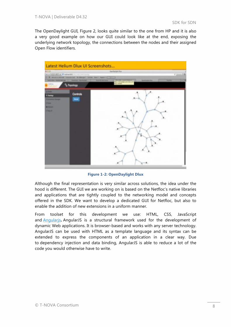
The OpenDaylight GUI, Figure 2, looks quite similar to the one from HP and it is also a very good example on how our GUI could look like at the end, exposing the underlying network topology, the connections between the nodes and their assigned Open Flow identifiers.
Figure 1-2: OpenDaylight Dlux
Although the final representation is very similar across solutions, the idea under the hood is different. The GUI we are working on is based on the Netfloc’s native libraries and applications that are tightly coupled to the networking model and concepts offered in the SDK. We want to develop a dedicated GUI for Netfloc, but also to enable the addition of new extensions in a uniform manner.
From toolset for this development we use: HTML, CSS, JavaScript and Angularjs. AngularJS is a structural framework used for the development of dynamic Web applications. It is browser-based and works with any server technology. AngularJS can be used with HTML as a template language and its syntax can be extended to express the components of an application in a clear way. Due to dependency injection and data binding, AngularJS is able to reduce a lot of the code you would otherwise have to write.
T-NOVA | Deliverable D4.32 SDK for SDN
© T-NOVA Consortium
9
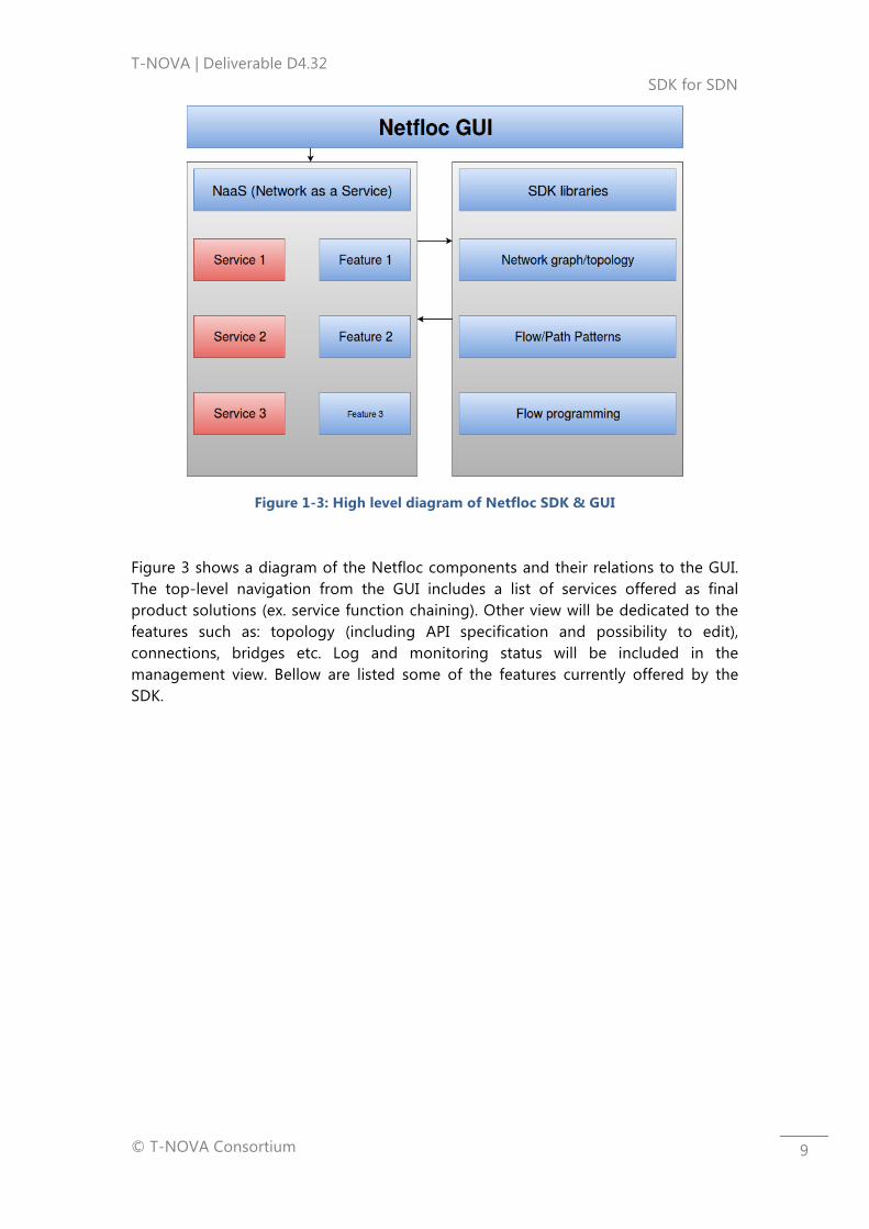
Figure 1-3: High level diagram of Netfloc SDK & GUI
Figure 3 shows a diagram of the Netfloc components and their relations to the GUI. The top-level navigation from the GUI includes a list of services offered as final product solutions (ex. service function chaining). Other view will be dedicated to the features such as: topology (including API specification and possibility to edit), connections, bridges etc. Log and monitoring status will be included in the management view. Bellow are listed some of the features currently offered by the SDK.

T-NOVA | Deliverable D4.32 SDK for SDN
© T-NOVA Consortium
10
1.3.3. Netfloc GUI existing features
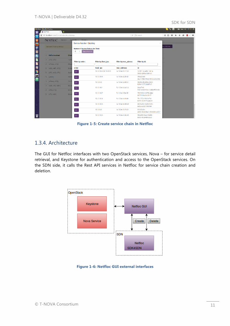
At this stage of the GUI prototype, there is an end-to-end support for the SFC library: the user is able to create new and delete an existing service function chain. This includes: a tabular list representation of the existing Neutron ports and their associated IPs, a draft view of the running VNFs, and their respective port name mappings in Nova. On service chain creation, Figure 1, the user should input the total number of neutron ports involved in the chain, including the sender and receiver ports and ingress and egress of each VNF.
Figure 1-4: Service chain summary view in Netfloc
The user can filter by IP, MAC addresses or port ID and assign the chain order number to the involved IDs in the chain. Under the hood the create chain function, calls the Netfloc’s create chain with either a success or error message displayed. When the user wants to remove an existing chain, the GUI offers an easy delete function by specifying the Chain ID. Here you can choose like in the picture below the chain/s you want to delete and then simply press on „Chain Actions“ and then „Delete“ to finally delete the chain. Other actions may be supported in future, depending on the functionality provided by Netfloc.
T-NOVA | Deliverable D4.32 SDK for SDN
© T-NOVA Consortium
11
Figure 1-5: Create service chain in Netfloc
1.3.4. Architecture
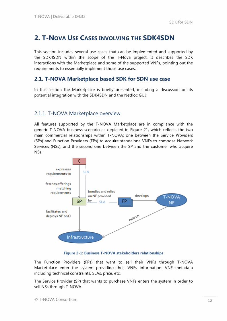
The GUI for Netfloc interfaces with two OpenStack services, Nova – for service detail retrieval, and Keystone for authentication and access to the OpenStack services. On the SDN side, it calls the Rest API services in Netfloc for service chain creation and deletion.
Figure 1-6: Netfloc GUI external interfaces
T-NOVA | Deliverable D4.32 SDK for SDN
© T-NOVA Consortium
12
2. T-NOVA USE CASES INVOLVING THE SDK4SDN
This section includes several use cases that can be implemented and supported by the SDK4SDN within the scope of the T-Nova project. It describes the SDK interactions with the Marketplace and some of the supported VNFs, pointing out the requirements to essentially implement those use cases.
2.1. T-NOVA Marketplace based SDK for SDN use case
In this section the Marketplace is briefly presented, including a discussion on its potential integration with the SDK4SDN and the Netfloc GUI.
2.1.1. T-NOVA Marketplace overview
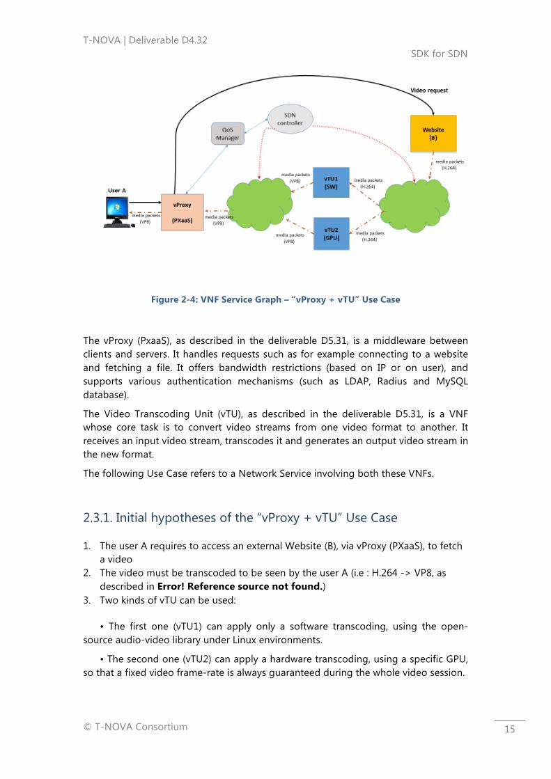
All features supported by the T-NOVA Marketplace are in compliance with the generic T-NOVA business scenario as depicted in Figure 21, which reflects the two main commercial relationships within T-NOVA: one between the Service Providers (SPs) and Function Providers (FPs) to acquire standalone VNFs to compose Network Services (NSs), and the second one between the SP and the customer who acquire NSs.
Figure 2-1: Business T-NOVA stakeholders relationships
The Function Providers (FPs) that want to sell their VNFs through T-NOVA Marketplace enter the system providing their VNFs information: VNF metadata including technical constraints, SLAs, price, etc.
The Service Provider (SP) that wants to purchase VNFs enters the system in order to sell NSs through T-NOVA.

T-NOVA | Deliverable D4.32 SDK for SDN
© T-NOVA Consortium
13
The SP is able to compose services acquiring VNFs by means of a brokerage that facilitates auctioning process among several FPs offering VNFs with similar features in order to achieve the lowest price offer. Then, the SP is able to compose NSs bundling VNFs, and advertise them creating offerings that include service description, SLA and prices. Those NSs are exposed through the T-NOVA marketplace to the customer.
The customer is able to search for the end-to-end network services offerings that can be composed by one or several VNFs, and with different SLA level and price in each offering.
To be able to offer a direct access from the Marketplace, the SDK for SDN has to essentially interface with it by using the set of APIs of the Marketplace or the Metadata description of the VNF and VNFC. More specifically in T-Nova, all relevant information is expressed using a metadata language. Since metadata permits the autonomous operation of each VNF and VNFC, direct interaction between the T-NOVA Orchestrator and VNFCs located inside of VNFs has been considered. The interaction with the marketplace is indirect through metadata descriptors. One option to be considered is embedding the Netfloc GUI as a separate service offered by the T-Nova Marketplace, where the SP can directly configure and compose its service offerings, thus having better visibility of the networking setup of its service offerings.
2.1.2. Service graph or forwarding graph
The SDK for SDN uses Service Chaining in order to build End-To-End service. They can be built by composing several VNFs, thanks to the metadata used in the descriptors. The VNF Forwarding Graph specification includes the information about the interconnection of VNFs and the traffic flows between them. More specifically, several VNFs can be connected to provide a service, and these connections can be visualised through a graph. The T-NOVA Orchestrator can use the VNF descriptors for creating this Service Graph (or forwarding graph) by interacting with the VNICs of the VNFs as presented in Figure 2-2.
Figure 2-2: VNF Service Graph

T-NOVA | Deliverable D4.32 SDK for SDN
© T-NOVA Consortium
14
2.2. vSA Use Case
The vSA appliance (see deliverable D5.31) has the goal to protect the networks from unwanted traffic, in passive (threat detection and reporting) or active (threat blocking) mode. Hence, possible use cases are all focused on the presence of attacks/threats at the network ingress point, to be countered by proper traffic filtering and forwarding actions.
An SDN controller, driven by a proper SDN application, can support the functionality of the vSA by extending and strengthening the scope of actions undertaken by the vSA Controller component in response to a detected threat. As default action, the FW Controller can tweak the rules of the Firewall component to change on the fly the acting traffic filtering policies. An external SDN application could use the information collected by the Monitoring Agent and sent to the Monitoring Server (even of multiple vSA instances across the network), to perform a deeper data analysis, and accordingly make wider scope reconfiguration of flows and paths. Another role of the SDN application can be to apply automatic policies to the incoming flows and selectively decide a traffic partitioning, forwarding only a given traffic subset to the vSA for deeper examination. This traffic diversion model is also proposed by Cisco as exemplary application of its OnePK toolkit [1].
Another use case integrating a vSA appliance with an SDN application can involve SFC, as hinted by IETF in a report on possible SFC use case [2]. In this case the vSA is inserted in a chain whose next step is a DPI function. This latter performs a virus risk analysis on the incoming packets, through a pattern matching research, and, in case an infection is detected, the related flow is redirected e.g. to an antivirus module or a parental control function.
2.3. “vProxy + vTU” Use Case
Figure 2-3: vSA VNF internal architecture and external interfaces
T-NOVA | Deliverable D4.32 SDK for SDN
© T-NOVA Consortium
15
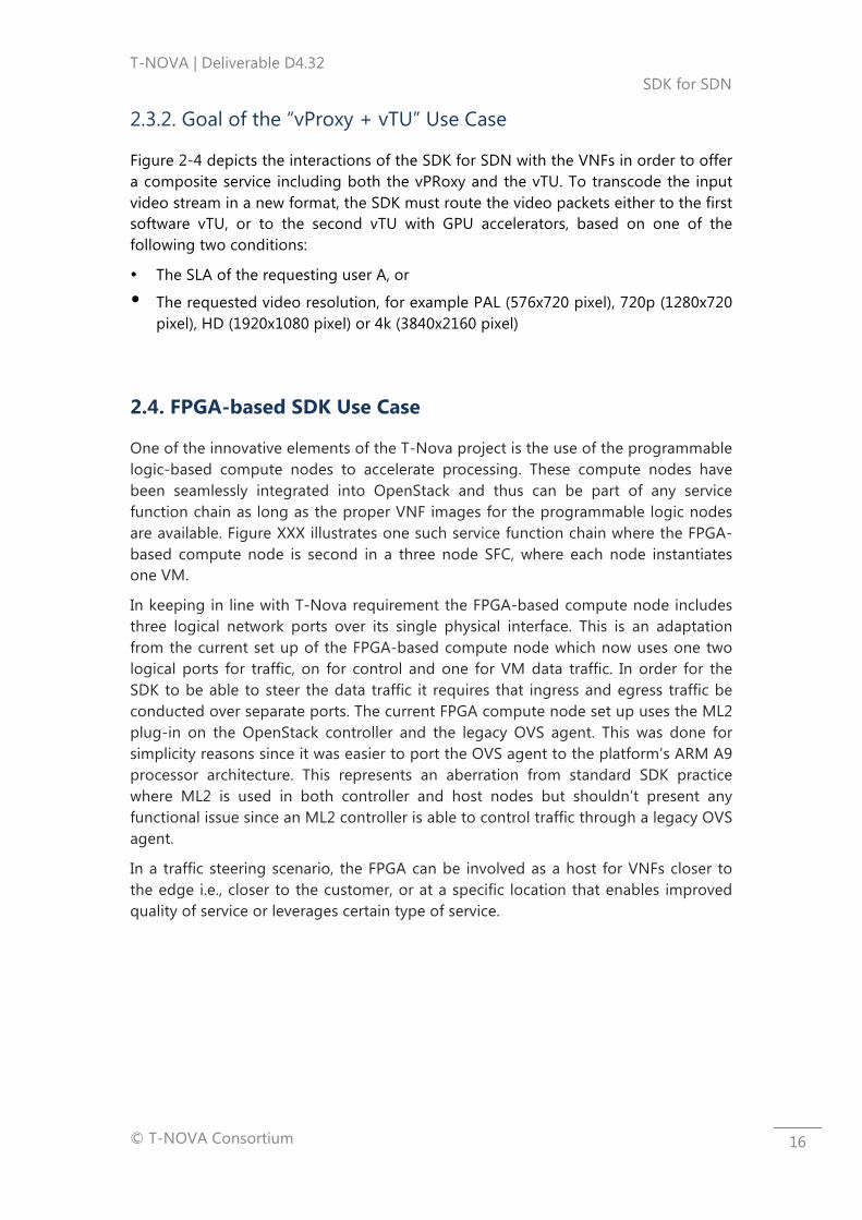
Figure 2-4: VNF Service Graph – “vProxy + vTU” Use Case
The vProxy (PxaaS), as described in the deliverable D5.31, is a middleware between clients and servers. It handles requests such as for example connecting to a website and fetching a file. It offers bandwidth restrictions (based on IP or on user), and supports various authentication mechanisms (such as LDAP, Radius and MySQL database).
The Video Transcoding Unit (vTU), as described in the deliverable D5.31, is a VNF whose core task is to convert video streams from one video format to another. It receives an input video stream, transcodes it and generates an output video stream in the new format.
The following Use Case refers to a Network Service involving both these VNFs.
2.3.1. Initial hypotheses of the “vProxy + vTU” Use Case
1. The user A requires to access an external Website (B), via vProxy (PXaaS), to fetch a video
2. The video must be transcoded to be seen by the user A (i.e : H.264 -> VP8, as described in Error! Reference source not found.)
3. Two kinds of vTU can be used:
• The first one (vTU1) can apply only a software transcoding, using the open-source audio-video library under Linux environments.
• The second one (vTU2) can apply a hardware transcoding, using a specific GPU, so that a fixed video frame-rate is always guaranteed during the whole video session.
T-NOVA | Deliverable D4.32 SDK for SDN
© T-NOVA Consortium
16
2.3.2. Goal of the “vProxy + vTU” Use Case
Figure 2-4 depicts the interactions of the SDK for SDN with the VNFs in order to offer a composite service including both the vPRoxy and the vTU. To transcode the input video stream in a new format, the SDK must route the video packets either to the first software vTU, or to the second vTU with GPU accelerators, based on one of the following two conditions:
• The SLA of the requesting user A, or
• The requested video resolution, for example PAL (576x720 pixel), 720p (1280x720 pixel), HD (1920x1080 pixel) or 4k (3840x2160 pixel)
2.4. FPGA-based SDK Use Case
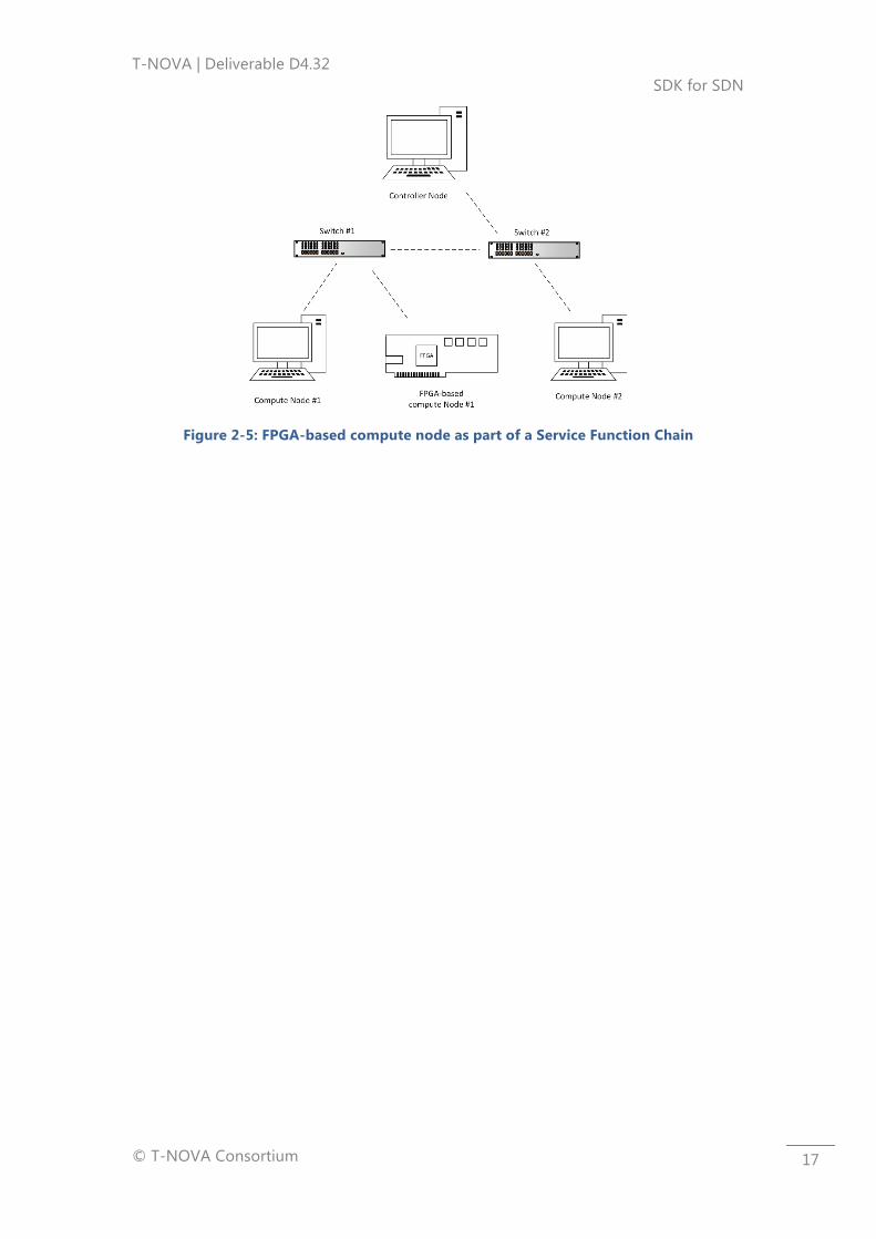
One of the innovative elements of the T-Nova project is the use of the programmable logic-based compute nodes to accelerate processing. These compute nodes have been seamlessly integrated into OpenStack and thus can be part of any service function chain as long as the proper VNF images for the programmable logic nodes are available. Figure XXX illustrates one such service function chain where the FPGA-based compute node is second in a three node SFC, where each node instantiates one VM.
In keeping in line with T-Nova requirement the FPGA-based compute node includes three logical network ports over its single physical interface. This is an adaptation from the current set up of the FPGA-based compute node which now uses one two logical ports for traffic, on for control and one for VM data traffic. In order for the SDK to be able to steer the data traffic it requires that ingress and egress traffic be conducted over separate ports. The current FPGA compute node set up uses the ML2 plug-in on the OpenStack controller and the legacy OVS agent. This was done for simplicity reasons since it was easier to port the OVS agent to the platform’s ARM A9 processor architecture. This represents an aberration from standard SDK practice where ML2 is used in both controller and host nodes but shouldn’t present any functional issue since an ML2 controller is able to control traffic through a legacy OVS agent.
In a traffic steering scenario, the FPGA can be involved as a host for VNFs closer to the edge i.e., closer to the customer, or at a specific location that enables improved quality of service or leverages certain type of service.
T-NOVA | Deliverable D4.32 SDK for SDN
© T-NOVA Consortium
17
Figure 2-5: FPGA-based compute node as part of a Service Function Chain

T-NOVA | Deliverable D4.32 SDK for SDN
© T-NOVA Consortium
18
3. SFC PROOF OF CONCEPT VALIDATION
3.1. The SDK4SDN (Netfloc) role in the T-Nova PoC Scenario
Deliverable 4.31 included a detailed description for all of the Netfloc's libraries and their functionality. As a reminder, Netfloc is used as a substitute for the native OpenStack networking service in order to engage with its ML2 plugin and provide a full SDN-based L2 capabilities of the entire cloud networking stack. Netfloc's libraries are derived from real application development use cases focused on optimising datacenter networks (in terms of minimising tunnelling overheads, maximising throughputs, enabling datapath redundancies etc.), and for network-level support on cloud applications.
The baseline motivation for some of the applications supported by the libraries in Netfloc, is to provide tenant isolation based on OpenFlow rather than the GRE and VXLAN tunnelling mechanisms used in OpenStack. Therefore the Isolation approach the Netfloc uses, is based completely on SDN and relies on the Neutron subnets in OpenStack to provide multi-tenant segregation.
Netfloc registers itself to ODL features via OSGI and depends mainly on the Neutron API, the OVSDB southbound feature and the OpenFlow plugin. What makes Netfloc essential to this scenario is the optimised approach it provides upon developing OpenStack based applications.
For the purpose of the T-Nova demo scenario, the traffic steering library from the SDK4SDN (Netfloc) was used to enforce service function chaining inside the SFC-PoP. Section 5.2 in Deliverable 4.22 elaborates in details the demonstration details of the SFC use case, including the results on the end-user side in terms of traffic and video output. In this deliverable further focus is given on the validation of the scenario, presenting the measurement results of the evaluation study.
3.2. Other T-Nova Components involved in the PoC Scenario
In this section the main components of the chain eco-system are described. Firstly, the architecture and functionality of the virtual Traffic Classifier is presented, along with its role in the proposed system. The second VNF is then described, which is a virtual Media Transcoder, followed by the details of the WAN Infrastructure Connection Manager.
3.2.1. Virtual traffic classifier – vTC
The purpose of the vTC is to analyse real-time network traffic, recognise specific applications and prioritise each traffic flow according to the application priority policies. Since this operation generates a significant workload, it is highly recommended to employ specific hardware acceleration features for efficient traffic processing. The vTC is developed within WP5 in T-NOVA and current forms as part of
T-NOVA | Deliverable D4.32 SDK for SDN
© T-NOVA Consortium
19
the OPNFV Yardstick [46] project supporting NFV workload characterization test cases.
In the paragraphs to follow, we describe in brief the functional characteristics and behaviour of the vTC.
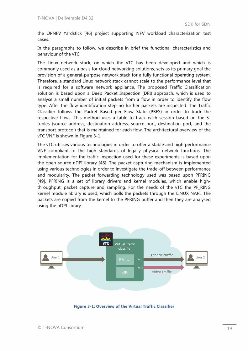
The Linux network stack, on which the vTC has been developed and which is commonly used as a basis for cloud networking solutions, sets as its primary goal the provision of a general-purpose network stack for a fully functional operating system. Therefore, a standard Linux network stack cannot scale to the performance level that is required for a software network appliance. The proposed Traffic Classification solution is based upon a Deep Packet Inspection (DPI) approach, which is used to analyse a small number of initial packets from a flow in order to identify the flow type. After the flow identification step no further packets are inspected. The Traffic Classifier follows the Packet Based per Flow State (PBFS) in order to track the respective flows. This method uses a table to track each session based on the 5-tuples (source address, destination address, source port, destination port, and the transport protocol) that is maintained for each flow. The architectural overview of the vTC VNF is shown in Figure 3-1.
The vTC utilises various technologies in order to offer a stable and high performance VNF compliant to the high standards of legacy physical network functions. The implementation for the traffic inspection used for these experiments is based upon the open source nDPI library [48]. The packet capturing mechanism is implemented using various technologies in order to investigate the trade-off between performance and modularity. The packet forwarding technology used was based upon PFRING [49]. PFRING is a set of library drivers and kernel modules, which enable high-throughput, packet capture and sampling. For the needs of the vTC the PF_RING kernel module library is used, which polls the packets through the LINUX NAPI. The packets are copied from the kernel to the PFRING buffer and then they are analysed using the nDPI library.
Figure 3-1: Overview of the Virtual Traffic Classifier
T-NOVA | Deliverable D4.32 SDK for SDN
© T-NOVA Consortium
20
3.2.2. Virtual media transcoder - vMT
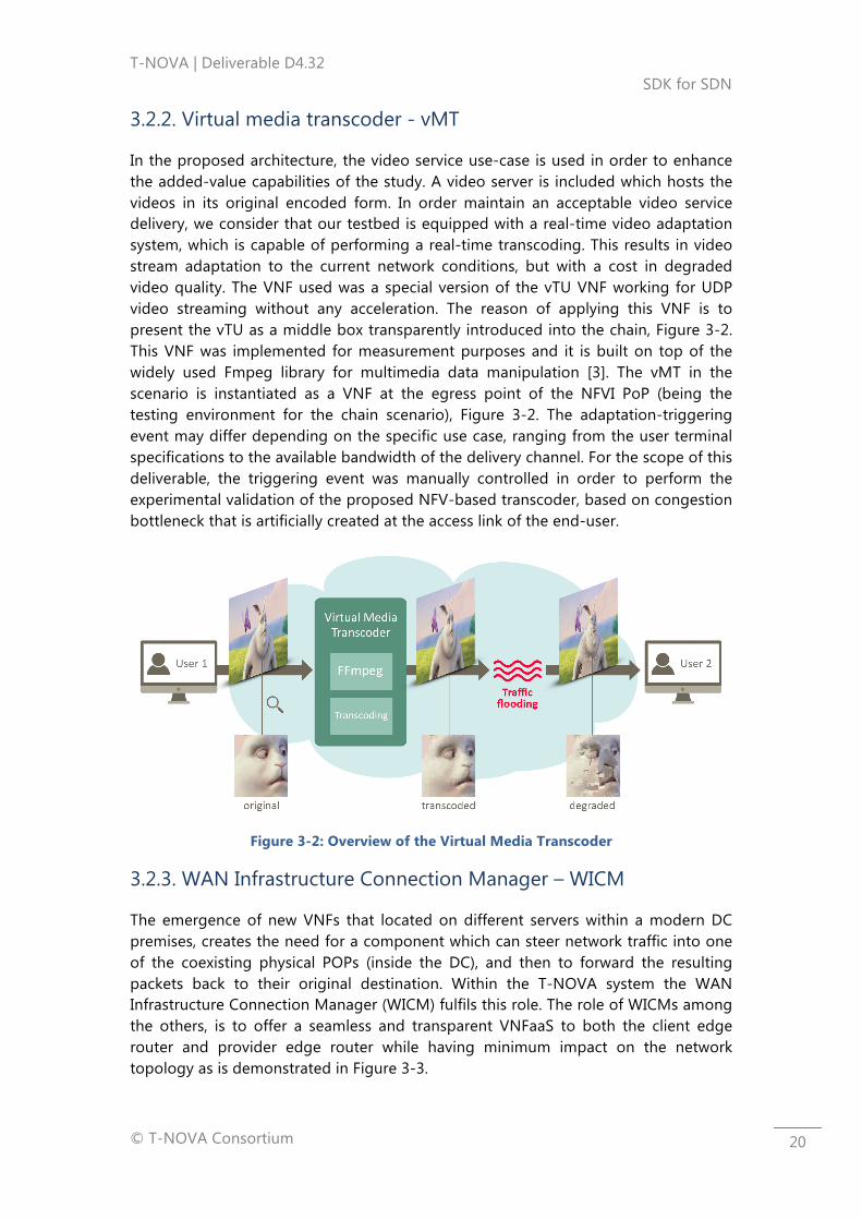
In the proposed architecture, the video service use-case is used in order to enhance the added-value capabilities of the study. A video server is included which hosts the videos in its original encoded form. In order maintain an acceptable video service delivery, we consider that our testbed is equipped with a real-time video adaptation system, which is capable of performing a real-time transcoding. This results in video stream adaptation to the current network conditions, but with a cost in degraded video quality. The VNF used was a special version of the vTU VNF working for UDP video streaming without any acceleration. The reason of applying this VNF is to present the vTU as a middle box transparently introduced into the chain, Figure 3-2. This VNF was implemented for measurement purposes and it is built on top of the widely used Fmpeg library for multimedia data manipulation [3]. The vMT in the scenario is instantiated as a VNF at the egress point of the NFVI PoP (being the testing environment for the chain scenario), Figure 3-2. The adaptation-triggering event may differ depending on the specific use case, ranging from the user terminal specifications to the available bandwidth of the delivery channel. For the scope of this deliverable, the triggering event was manually controlled in order to perform the experimental validation of the proposed NFV-based transcoder, based on congestion bottleneck that is artificially created at the access link of the end-user.
Figure 3-2: Overview of the Virtual Media Transcoder
3.2.3. WAN Infrastructure Connection Manager – WICM
The emergence of new VNFs that located on different servers within a modern DC premises, creates the need for a component which can steer network traffic into one of the coexisting physical POPs (inside the DC), and then to forward the resulting packets back to their original destination. Within the T-NOVA system the WAN Infrastructure Connection Manager (WICM) fulfils this role. The role of WICMs among the others, is to offer a seamless and transparent VNFaaS to both the client edge router and provider edge router while having minimum impact on the network topology as is demonstrated in Figure 3-3.
T-NOVA | Deliverable D4.32 SDK for SDN
© T-NOVA Consortium
21
WICM [4] controls an OpenFlow Pica8 switch through an ODL SDN controller that connects one or more client edge routers to one or more provider edge routers. By default, WICM configures the switch to connect the CE router to the PE router by closing the MPLS IP VPN attachment circuit. This process ensures connectivity to the clients, but not yet a VNF access. Once a client purchases a VNF service, the WICM reconfigures the switch in order to redirect for processing, the client's traffic into the assigned SFC-PoP. WICM also configures the switch to properly forward back the resulting packets coming from the SFC-PoP.
If at any time the client decides to stop using the VNFs services, the WICM configures the switch back to the default state, ensuring always the connectivity service. The switch is strategically placed in between the edges so it can intercept and redirect all the traffic coming in, or going out of each of the clients.
3.3. SFC Experimental Setup
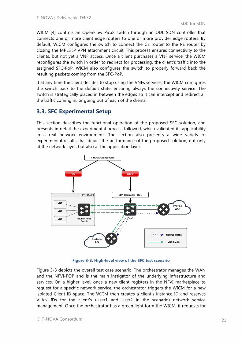
This section describes the functional operation of the proposed SFC solution, and presents in detail the experimental process followed, which validated its applicability in a real network environment. The section also presents a wide variety of experimental results that depict the performance of the proposed solution, not only at the network layer, but also at the application layer.
Figure 3-3: High-level view of the SFC test scenario
Figure 3-3 depicts the overall test case scenario. The orchestrator manages the WAN and the NFVI-POP and is the main instigator of the underlying infrastructure and services. On a higher level, once a new client registers in the NFVI marketplace to request for a specific network service, the orchestrator triggers the WICM for a new isolated Client ID space. The WICM then creates a client's instance ID and reserves VLAN IDs for the client's (User1 and User2 in the scenario) network service management. Once the orchestrator has a green light form the WICM, it requests for
T-NOVA | Deliverable D4.32 SDK for SDN
© T-NOVA Consortium
22
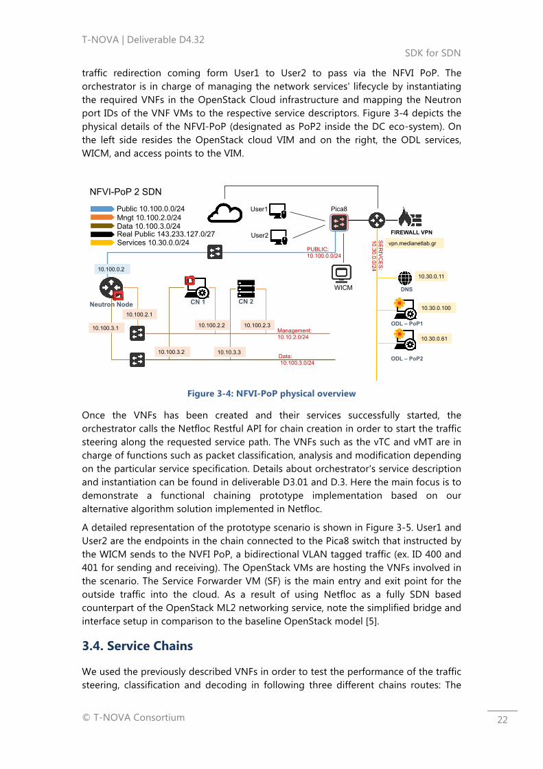
traffic redirection coming form User1 to User2 to pass via the NFVI PoP. The orchestrator is in charge of managing the network services' lifecycle by instantiating the required VNFs in the OpenStack Cloud infrastructure and mapping the Neutron port IDs of the VNF VMs to the respective service descriptors. Figure 3-4 depicts the physical details of the NFVI-PoP (designated as PoP2 inside the DC eco-system). On the left side resides the OpenStack cloud VIM and on the right, the ODL services, WICM, and access points to the VIM.
Figure 3-4: NFVI-PoP physical overview
Once the VNFs has been created and their services successfully started, the orchestrator calls the Netfloc Restful API for chain creation in order to start the traffic steering along the requested service path. The VNFs such as the vTC and vMT are in charge of functions such as packet classification, analysis and modification depending on the particular service specification. Details about orchestrator's service description and instantiation can be found in deliverable D3.01 and D.3. Here the main focus is to demonstrate a functional chaining prototype implementation based on our alternative algorithm solution implemented in Netfloc.
A detailed representation of the prototype scenario is shown in Figure 3-5. User1 and User2 are the endpoints in the chain connected to the Pica8 switch that instructed by the WICM sends to the NVFI PoP, a bidirectional VLAN tagged traffic (ex. ID 400 and 401 for sending and receiving). The OpenStack VMs are hosting the VNFs involved in the scenario. The Service Forwarder VM (SF) is the main entry and exit point for the outside traffic into the cloud. As a result of using Netfloc as a fully SDN based counterpart of the OpenStack ML2 networking service, note the simplified bridge and interface setup in comparison to the baseline OpenStack model [5].
3.4. Service Chains
We used the previously described VNFs in order to test the performance of the traffic steering, classification and decoding in following three different chains routes: The
10.30.0.11
SE
RIV
CE
S:
10.30.0.0/24
DNS
PUBLIC: 10.100.0.0/24
FIREWALL VPN
CN 1 CN 2
Management: 10.10.2.0/24
Neutron Node
10.100.0.2
10.100.2.2 10.100.2.3
vpn.medianetlab.gr
Public 10.100.0.0/24 Mngt 10.100.2.0/24 Data 10.100.3.0/24 Real Public 143.233.127.0/27
NFVI-PoP 2 SDN
10.30.0.100
10.30.0.61
Data: 10.100.3.0/24
10.100.3.2 10.10.3.3 ODL – PoP2
ODL – PoP1 10.100.3.1
10.100.2.1
Services 10.30.0.0/24
Pica8 User1
User2
WICM
T-NOVA | Deliverable D4.32 SDK for SDN
© T-NOVA Consortium
23
first one is a direct User1 to User 2 communication without redirection (service chain disabled); the second one involves one chain comprising two vTC VNFs along the way between the endpoints; the third consists of two chains including two vTC instances and one vMT. Finally the fourth set of measurements involves the vMT alone in the chain.
Following are the chain setups as described:
Direct: User1 à User2
Chain1: User1 à vTC1 (class.) à vTC2 (frwd.) à User2
Chain2: User1 à vTC1 (class.) à vTC2 (frwd); vTC1 (class.) à vMT (transcoding) à User2
Chain3: User1 à vTC (class.) à vMT (transc.) à User2
3.5. Validation Measurements
The experimental results demonstrate the characterisation of the SFC architecture and include a performance comparison of throughput, packet loss, latency and jitter for the case of chain absence plus the three chains setups.
3.5.1. Initial datacenter network measurements
To evaluate the network representation model and the SDN performance of Netfloc and OpenStack, we performed initial performance evaluations in earlier development cycles. The measurements focused on SDN based tenant segregation using the standard OpenStack isolation approach of applying GRE and VXLAN encapsulation of the IP header versus the Netfloc networking model based on direct Open Flow forwarding on L2. Unlike in OpenStack, where the integration bridge forwards the traffic to the tunnel bridge, for VLAN to GRE en(de)capsulation (and vice versa), in our approach we created a single L2 domain and directly attached the external bridge to a NIC on a compute node in order to explicitly forward the traffic via that bridge.
The latency and bandwidth measurements were performed in order to evaluate the flow based networking approach. We encountered a significant latency difference gain with almost the same bandwidth values for a thousand standard sized packets sent with a 0.5sec interval. The initial results confirmed the advantage of the non-tunnelling isolation approach and provided the necessary evidence for adopting SDN principals in resolving datacenter-networking issues. They also foster the aforementioned methodology to develop advanced services and applications in Netfloc, such as SFC support as a most prominent use case.
Server CPU Memory
Network Node Intel Pentium 4 CPU3.00GHz 2 MB Cache
2.4GB
T-NOVA | Deliverable D4.32 SDK for SDN
© T-NOVA Consortium
24
Control Node 4Core Intel Xeon CPU E3-1240 V23.40GHz 8 MB Cache
15GB
Compute Node 4Core Intel Xeon CPU E3-1240 V23.40GHz 8 MB Cache
15GB
Switch
AMD Sempron Processor 2800+ Cache 256KB
993MB
SDN Node 4Core Intel Core2 Quad CPU Q84002.66GHz 2 MB Cache
3GB
WICM Node 4Core Intel Core2 Quad CPU Q66002.40GHz 4MB Cache
7.8GB
User1 AMD Sempron Processor 2800+ 256 KB Cache
457MB
User 2 2Core Intel Core i7-5557U CPU 3.10GHz 4MB Cache
15GB
Servers’ Operative System
Ubuntu 14.04.4 LTS
Virtual Switch Open vSwitch v2.3.2
OpenFlow versions 0x1:0x1
Table 3-1: Demo scenario hardware specifications
3.5.2. Measurements setup
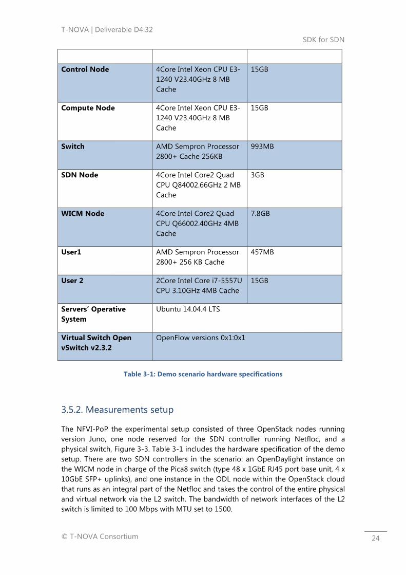
The NFVI-PoP the experimental setup consisted of three OpenStack nodes running version Juno, one node reserved for the SDN controller running Netfloc, and a physical switch, Figure 3-3. Table 3-1 includes the hardware specification of the demo setup. There are two SDN controllers in the scenario: an OpenDaylight instance on the WICM node in charge of the Pica8 switch (type 48 x 1GbE RJ45 port base unit, 4 x 10GbE SFP+ uplinks), and one instance in the ODL node within the OpenStack cloud that runs as an integral part of the Netfloc and takes the control of the entire physical and virtual network via the L2 switch. The bandwidth of network interfaces of the L2 switch is limited to 100 Mbps with MTU set to 1500.

T-NOVA | Deliverable D4.32 SDK for SDN
© T-NOVA Consortium
25
Figure 3-5: NFVI-PoP Service chain details
We used the D-ITG [6] tool for traffic generation and results collection between the two endpoints User1 and User2. Burst frames were sent repetitively with a 0.2sec interval and packet sizes varying from 64 to 1450bytes. For the video evaluations we used a Matlab implementation of the Structural Similarity Index (SSIM) as described in [7].
The evaluation objectives are: (1) effectiveness and correctness of the traffic steering mechanism in expanded DC setup with more then just a single Cloud VIM (2) robustness of the chain setup (3) efficiency of the traffic redirection and packets manipulation. The goal of the extended chain pilot was to test the SFC algorithm as a proof of concept for seamless integration of the involved components within a wider NFVI scope. The experimental setup covered in this paper considers SFC as a whole and thus the results are based on E2E measurements (in User1 and User2), as part of SFC performance measurements recommended by the IETF draft [8]. Hop by hop experiments on isolated SFC segments are out of scope for this paper and would further be elaborated in a future work.
3.5.3. Results and analysis
This section presents the analysis of the demo measurements as a comparison of TCP, UDP, ICMP and video traffic performance between baseline client/server communication without redirection and Chain1 and Chain2 presented in the previous section.
3.5.3.1. Throughput
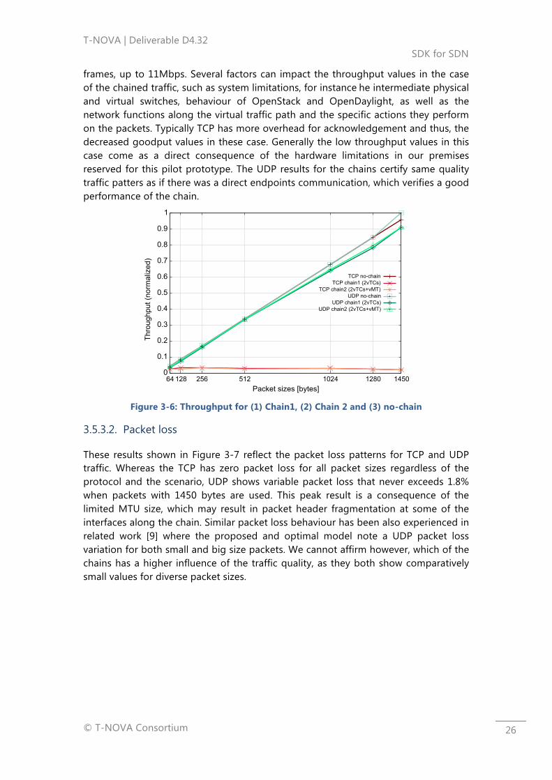
Figure 3-6 depicts the throughput values as a function of different packet sizes. It is represented as a normalised scale with maximum values reaching 12 Mbps. The throughput follows a linear incremental value as the size of the frames increases for all traffic types in a similar fashion except for TCP traffic in case of service chain. Here, the throughput oscillates between 0, 25 and 0, 35Mbps whereas the baseline no chain TCP throughput increases 30 times from the smallest to the biggest packet
T-NOVA | Deliverable D4.32 SDK for SDN
© T-NOVA Consortium
26
frames, up to 11Mbps. Several factors can impact the throughput values in the case of the chained traffic, such as system limitations, for instance he intermediate physical and virtual switches, behaviour of OpenStack and OpenDaylight, as well as the network functions along the virtual traffic path and the specific actions they perform on the packets. Typically TCP has more overhead for acknowledgement and thus, the decreased goodput values in these case. Generally the low throughput values in this case come as a direct consequence of the hardware limitations in our premises reserved for this pilot prototype. The UDP results for the chains certify same quality traffic patters as if there was a direct endpoints communication, which verifies a good performance of the chain.
Figure 3-6: Throughput for (1) Chain1, (2) Chain 2 and (3) no-chain
3.5.3.2. Packet loss
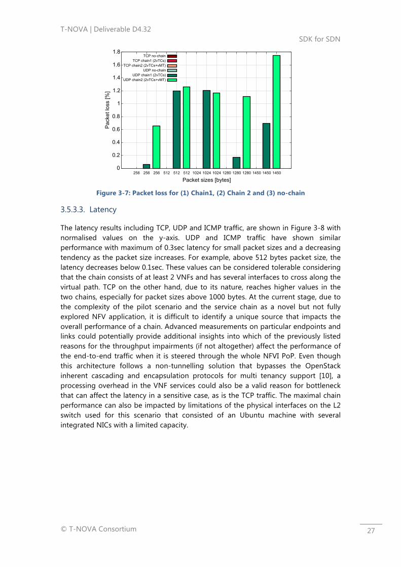
These results shown in Figure 3-7 reflect the packet loss patterns for TCP and UDP traffic. Whereas the TCP has zero packet loss for all packet sizes regardless of the protocol and the scenario, UDP shows variable packet loss that never exceeds 1.8% when packets with 1450 bytes are used. This peak result is a consequence of the limited MTU size, which may result in packet header fragmentation at some of the interfaces along the chain. Similar packet loss behaviour has been also experienced in related work [9] where the proposed and optimal model note a UDP packet loss variation for both small and big size packets. We cannot affirm however, which of the chains has a higher influence of the traffic quality, as they both show comparatively small values for diverse packet sizes.
T-NOVA | Deliverable D4.32 SDK for SDN
© T-NOVA Consortium
27
Figure 3-7: Packet loss for (1) Chain1, (2) Chain 2 and (3) no-chain
3.5.3.3. Latency
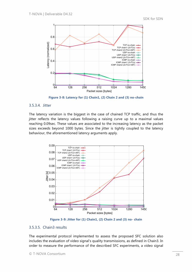
The latency results including TCP, UDP and ICMP traffic, are shown in Figure 3-8 with normalised values on the y-axis. UDP and ICMP traffic have shown similar performance with maximum of 0.3sec latency for small packet sizes and a decreasing tendency as the packet size increases. For example, above 512 bytes packet size, the latency decreases below 0.1sec. These values can be considered tolerable considering that the chain consists of at least 2 VNFs and has several interfaces to cross along the virtual path. TCP on the other hand, due to its nature, reaches higher values in the two chains, especially for packet sizes above 1000 bytes. At the current stage, due to the complexity of the pilot scenario and the service chain as a novel but not fully explored NFV application, it is difficult to identify a unique source that impacts the overall performance of a chain. Advanced measurements on particular endpoints and links could potentially provide additional insights into which of the previously listed reasons for the throughput impairments (if not altogether) affect the performance of the end-to-end traffic when it is steered through the whole NFVI PoP. Even though this architecture follows a non-tunnelling solution that bypasses the OpenStack inherent cascading and encapsulation protocols for multi tenancy support [10], a processing overhead in the VNF services could also be a valid reason for bottleneck that can affect the latency in a sensitive case, as is the TCP traffic. The maximal chain performance can also be impacted by limitations of the physical interfaces on the L2 switch used for this scenario that consisted of an Ubuntu machine with several integrated NICs with a limited capacity.
T-NOVA | Deliverable D4.32 SDK for SDN
© T-NOVA Consortium
28
Figure 3-8: Latency for (1) Chain1, (2) Chain 2 and (3) no-chain
3.5.3.4. Jitter
The latency variation is the biggest in the case of chained TCP traffic, and thus the jitter reflects the latency values following a raising curve up to a maximal values reaching 0.09sec. These values are associated to the increasing latency as the packet sizes exceeds beyond 1000 bytes. Since the jitter is tightly coupled to the latency behaviour, the aforementioned latency arguments apply.
Figure 3-9: Jitter for (1) Chain1, (2) Chain 2 and (3) no- chain
3.5.3.5. Chain3 results
The experimental protocol implemented to assess the proposed SFC solution also includes the evaluation of video signal's quality transmissions, as defined in Chain3. In order to measure the performance of the described SFC experiments, a video signal

T-NOVA | Deliverable D4.32 SDK for SDN
© T-NOVA Consortium
29
was transmitted end-to-end, from User1 to User2. The quality is measured at User2 as the video is saved, while being received. The stored video sequence is compared to the original sequence using the Structural Similarity Index (SSIM) [11], which is a widely used and recognized video quality assessment (VQA) method. SSIM is a full reference video quality metric, which means that in order to measure the video's quality both the reference and the transcoded video are needed, thus the saving of the received video signal.
The video signal used was the BigBuckBunny reference video [12], which comprises of 14,315 frames and lasts approximately 9 minutes. The selected video signal provides a perfect candidate for evaluating video quality over an error-prone service environment, as it simulates a real life scenario. The video was transmitted from User1 to User2 in 5 difference scenarios. In each scenario the network was flooded with traffic, each time at a different rate. The group of throughput rates selected varied from 0 to 95Mbps. In the following figure we present the SSIM video quality index of the received video signal in relation to the traffic we injected to the network, during the video transmission. Additionally, in the table the detailed values of SSIM with their corresponding traffic throughput values are presented.
Figure 3-10: SSIM Video quality assessment results
As Figure 3-9 depicts, the traffic injection greatly impacts the quality of the received video signals as the traffic throughput is increased. In terms of the SFC impact we can see that for the values of 0 Mbps and 10 Mbps the SSIM index for the received video signal is satisfactory, which shows that the SFC and vMT impact on video degradation is acceptable. An alternative for improved video quality perception, is based on the integration of, a packet acceleration framework such as Intel's Dataplane Development Kit (DPDK) [13]. Such software acceleration increases the network's capacity and throughput, as shown in [14].
As a general conclusion, the results validate the chaining methodology and confirm consistency across the tested chains. The cause for a degraded behaviour within the chain can come from different sources: a network outage (physical and virtual), SDN controller limitations, and VNFs' service type constraints. Limiting to the scope of the
T-NOVA | Deliverable D4.32 SDK for SDN
© T-NOVA Consortium
30
chosen pilot use case, we proved the validity of the chaining method and demonstrated good overall performance in the chaining methodology approach when comparing chained traffic with variable packet sizes vs a baseline use case without redirection. In future work we will focus on additional SFC analysis using hop by hop measurements at different endpoints along the chain in order to compare these results with a more precise and deterministic vision of the intermediate traffic behaviour.
T-NOVA | Deliverable D4.32 SDK for SDN
© T-NOVA Consortium
31
4. CONCLUSION & NEXT STEPS
The work presented in these deliverable focuses on updates in Task 4.3 during the period between January and April 2016. The main objective was to outline the further developments of the SDK for SDN and depict some details of the Year 2 demo with respect to the SFC details and validation measurements. Moreover it presents in details the GUI for SDN that ZHAW was developing as a management interface to facilitate the interaction with the SDK for SDN and create applications using its libraries. After one year of implementation engagement in Task 4.3, this deliverable is reflection of the finalized activities as foreseen in the task description: from code implementation, to integration activities, SFC demo involving several T-Nova components, and finally providing characterization results. Moreover it elaborates on alternative use cases and integration challenges to be potentially met in the upcoming months of the project duration.
To sum up, these are the concrete goals achieved over one year course:
- Netfloc as SDN-driven SDK for datacenter network programming involving libraries for tenant isolation based on L2 OpenFlow approach, resilience in datacenter clouds, and SDN-driven traffic steering
- SFC PoC validation based on OpenFlow targeting effective and robust end-to-end delivery solution in NFVI environments that fills in the lack or real datacenter evaluation and validation measurements
- Testing on TCP/UDP and video traffic repeated over several chain scenarios and validated the system prototype correctness and effectiveness
- Comprehensive and through State of the Art analysis of the existing solutions for SDK in SDN, NFVI standardization groups and activities.
A future research challenge coming from this work can focus on extending the measurements by embracing a diverse set of VNF instances and use case scenarios in order to achieve production-quality implementation. A decoupled hop-by-hop benchmarking measurement on the intermediate chain segments can be a way to go in order to accurately test the fault-tolerance. Alternative option is focus on extending the SDK library set with a QoS and monitoring libraries based on OpenFlow. Finally integration activities with the orchestrator to achieve automatic deployment of end-to-end solution involving the SDK, would be a preferred target within the scope of the T-Nova project and WP7.

T-NOVA | Deliverable D4.32 SDK for SDN
© T-NOVA Consortium
32
5. REFERENCES
[1] „Software-Defined Networking and Network,“ [Online]. Available: http://www.cisco.com/c/dam/en_us/solutions/industries/docs/gov/software_defined_networking.pdf .
[2] W. Liu, „Service Chaining Use Cases,“ 15 7 2013. [Online]. Available: https://tools.ietf.org/pdf/draft-liu-service-chaining-use-cases-01.pdf .
[3] „FFMPEG,“ [Online]. Available: https://www.ffmpeg.org/.
[4] „Infrastructure and Connectivity Manager,“ [Online]. Available: https://github.com/T-NOVA/WICM.
[5] „Open{S}tack networking details,“ [Online]. Available: https://www.rdoproject.org/networking/networking-in-too-much-detail/.
[6] A. B. e. al., „A tool for the generation of realistic network workload for emerging networking scenarios,“ 2012. [Online]. Available: http://dx.doi.org/10.1016/j.comnet.2012.02.019.
[7] W. e. al., „Image Quality Assessment: From Error Visibility to Structural Similarity,“ 4 2004. [Online]. Available: http://dx.doi.org/10.1109/TIP.2003.819861.
[8] G. Agrawal, „Performance Measurement Architecture for SFC,“ December 2015. [Online]. Available: http://www.ietf.org/internet-drafts/draft-sfc-agv-performance-measurement-architecture-00.txt.
[9] R. Kawashima und H. Matsuo, „Non-tunneling Edge-Overlay Model Using OpenFlow for Cloud Datacenter,“ 2013. [Online].
[10]
„Open{S}tack networking details,“ [Online]. Available: https://www.rdoproject.org/networking/networking-in-too-much-detail/.
[11]
Wang et al., „Image Quality Assessment: From Error Visibility to Structural Similarity,“ April 2004. [Online]. Available: http://dx.doi.org/10.1109/TIP.2003.819861.
[12]
„Big Buck Bunny Reference Video,“ [Online]. Available: https://peach.blender.org/.
[13]
„DPDK,“ [Online]. Available: http://dpdk.org/.
[14]
Kourtis et al., „Enhancing VNF Performance by Exploiting SR-IOV and DPDK Packet Processing Acceleration,“ 2015. [Online].

T-NOVA | Deliverable D4.32 SDK for SDN
© T-NOVA Consortium
33
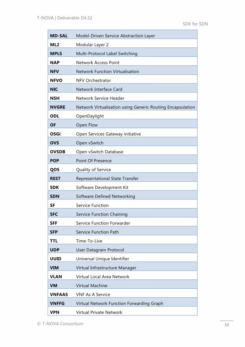
6. LIST OF ACRONYMS
Acronym Description
API Application Programming Interface
ARP Address Resolution Protocol
BGP Border Gateway Protocol
BUM Broadcast, Unknown unicast and Multicast
CP Control Plane
CPU Central Processing Unit
CRUD Create, Read, Update, Delete
DC Data Centre
DCN Distributed Cloud Networking
DOVE Distributed Overlay Virtual Ethernet
DPI Deep Packet Inspection
FTP File Transfer Protocol
FW Firewall
GPE Generic Protocol Extension
GRE Generic Routing Encapsulation
GW Gateway
HA High Availability
HPE Hewlett Packard Enterprise
HTTP HyperText Transport Protocol
IP Internet Protocol
ISP Internet Service Provider
IVM Infrastructure Virtualisation Management
JVM Java Virtual Machine
L2 Layer 2
L3 Layer 3
L4 Layer 4
LB Load Balancer
MAC Medium Access Control
T-NOVA | Deliverable D4.32 SDK for SDN
© T-NOVA Consortium
34
MD-SAL Model-Driven Service Abstraction Layer
ML2 Modular Layer 2
MPLS Multi-Protocol Label Switching
NAP Network Access Point
NFV Network Function Virtualisation
NFVO NFV Orchestrator
NIC Network Interface Card
NSH Network Service Header
NVGRE Network Virtualisation using Generic Routing Encapsulation
ODL OpenDaylight
OF Open Flow
OSGi Open Services Gateway initiative
OVS Open vSwitch
OVSDB Open vSwitch Database
POP Point Of Presence
QOS Quality of Service
REST Representational State Transfer
SDK Software Development Kit
SDN Software Defined Networking
SF Service Function
SFC Service Function Chaining
SFF Service Function Forwarder
SFP Service Function Path
TTL Time-To-Live
UDP User Datagram Protocol
UUID Universal Unique Identifier
VIM Virtual Infrastructure Manager
VLAN Virtual Local Area Network
VM Virtual Machine
VNFAAS VNF As A Service
VNFFG Virtual Network Function Forwarding Graph
VPN Virtual Private Network
T-NOVA | Deliverable D4.32 SDK for SDN
© T-NOVA Consortium
35
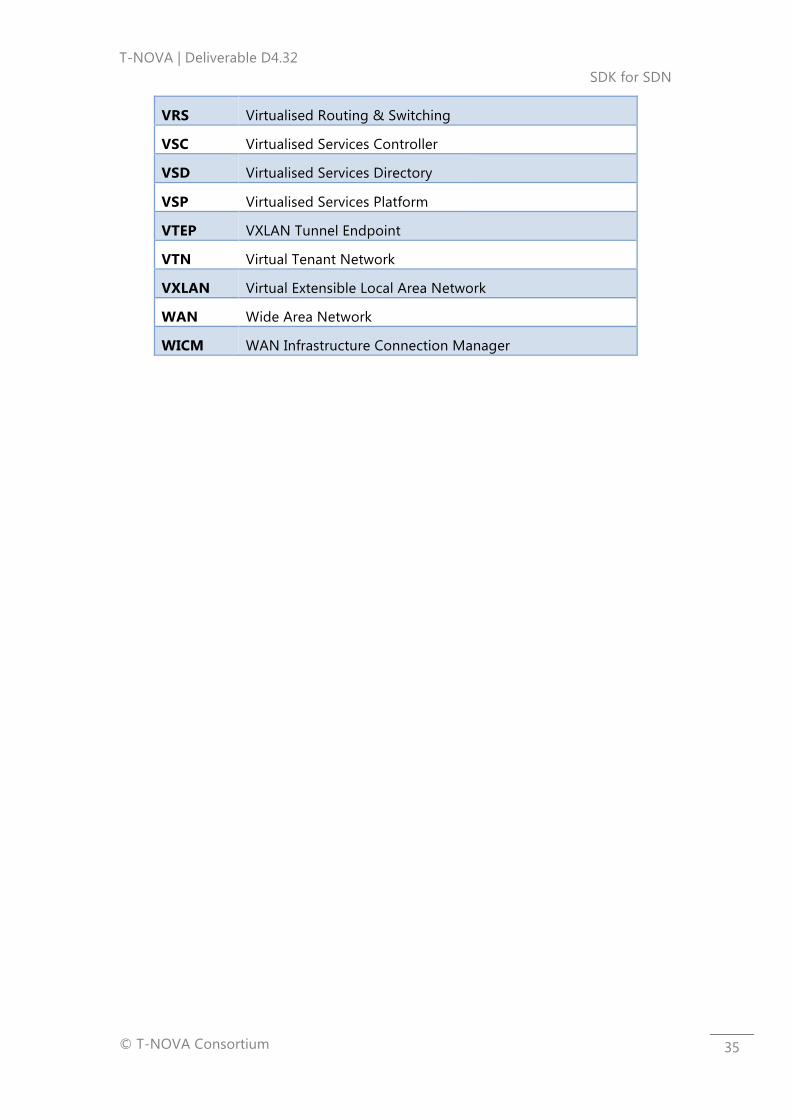
VRS Virtualised Routing & Switching
VSC Virtualised Services Controller
VSD Virtualised Services Directory
VSP Virtualised Services Platform
VTEP VXLAN Tunnel Endpoint
VTN Virtual Tenant Network
VXLAN Virtual Extensible Local Area Network
WAN Wide Area Network
WICM WAN Infrastructure Connection Manager