screenos cli reference guide: ipv6 command descriptions · 2014-09-23 · local-id .....107...
TRANSCRIPT

Security Products
ScreenOS CLI Reference Guide:IPv6 Command Descriptions
Release
6.3.0, Rev. 02
Published: 2012-12-11
Revision 02
Copyright © 2012, Juniper Networks, Inc.

Juniper Networks, Inc.1194 North Mathilda AvenueSunnyvale, California 94089USA408-745-2000www.juniper.net
Juniper Networks, Junos, Steel-Belted Radius, NetScreen, and ScreenOS are registered trademarks of Juniper Networks, Inc. in the UnitedStates and other countries. JunosE is a trademark of Juniper Networks, Inc. All other trademarks, service marks, registered trademarks, orregistered service marks are the property of their respective owners.Juniper Networks assumes no responsibility for any inaccuracies in this document. Juniper Networks reserves the right to change, modify,transfer, or otherwise revise this publication without notice.Products made or sold by Juniper Networks or components thereof might be covered by one or more of the following patents that areowned by or licensed to Juniper Networks: U.S. Patent Nos. 5,473,599, 5,905,725, 5,909,440, 6,192,051, 6,333,650, 6,359,479, 6,406,312,6,429,706, 6,459,579, 6,493,347, 6,538,518, 6,538,899, 6,552,918, 6,567,902, 6,578,186, and 6,590,785.Copyright © 2009, Juniper Networks, Inc.All rights reserved.
Revision HistoryDecember 2012—Revision 02
Content subject to change. The information in this document is current as of the date listed in the revision history.
SOFTWARE LICENSE
The terms and conditions for using this software are described in the software license contained in the acknowledgment to your purchaseorder or, to the extent applicable, to any reseller agreement or end-user purchase agreement executed between you and Juniper Networks.By using this software, you indicate that you understand and agree to be bound by those terms and conditions.
Generally speaking, the software license restricts the manner in which you are permitted to use the software and may contain prohibitionsagainst certain uses. The software license may state conditions under which the license is automatically terminated. You should consultthe license for further details.
For complete product documentation, please see the Juniper Networks Website atwww.juniper.net/techpubs.
ENDUSER LICENSE AGREEMENT
The Juniper Networks product that is the subject of this technical documentation consists of (or is intended for use with) Juniper Networkssoftware. Use of such software is subject to the terms and conditions of the End User License Agreement (“EULA”) posted at
http://www.juniper.net/support/eula.html. By downloading, installing or using such software, you agree to the terms and conditionsof that EULA.
Copyright © 2012, Juniper Networks, Inc.ii

Abbreviated Table of Contents
Part 1 About This Guide
Chapter 1 About This Guide . . . . . . . . . . . . . . . . . . . . . . . . . . . . . . . . . . . . . . . . . . . . . . . . . . . 3
Part 2 Command Reference
Chapter 2 active-user Through event . . . . . . . . . . . . . . . . . . . . . . . . . . . . . . . . . . . . . . . . . . 13
Chapter 3 exit Through nsmgmt . . . . . . . . . . . . . . . . . . . . . . . . . . . . . . . . . . . . . . . . . . . . . . 83
Chapter 4 ntp Through RIPng . . . . . . . . . . . . . . . . . . . . . . . . . . . . . . . . . . . . . . . . . . . . . . . 185
Chapter 5 rm Through zone . . . . . . . . . . . . . . . . . . . . . . . . . . . . . . . . . . . . . . . . . . . . . . . . . 255
Part 3 Appendix
Appendix A Interfaces . . . . . . . . . . . . . . . . . . . . . . . . . . . . . . . . . . . . . . . . . . . . . . . . . . . . . . . 355
Appendix B Zones . . . . . . . . . . . . . . . . . . . . . . . . . . . . . . . . . . . . . . . . . . . . . . . . . . . . . . . . . . . 357
Part 4 Index
Index . . . . . . . . . . . . . . . . . . . . . . . . . . . . . . . . . . . . . . . . . . . . . . . . . . . . . . . . . . . 361
iiiCopyright © 2012, Juniper Networks, Inc.

Copyright © 2012, Juniper Networks, Inc.iv
IPv6 Command Descriptions

Table of Contents
Part 1 About This Guide
Chapter 1 About This Guide . . . . . . . . . . . . . . . . . . . . . . . . . . . . . . . . . . . . . . . . . . . . . . . . . . . 3
Document Organization . . . . . . . . . . . . . . . . . . . . . . . . . . . . . . . . . . . . . . . . . . . . . . . 3
Document Conventions . . . . . . . . . . . . . . . . . . . . . . . . . . . . . . . . . . . . . . . . . . . . . . . 3
Command Line Interface Conventions . . . . . . . . . . . . . . . . . . . . . . . . . . . . . . . . 4
Dependency Delimiters . . . . . . . . . . . . . . . . . . . . . . . . . . . . . . . . . . . . . . . . 4
Embedded Dependencies . . . . . . . . . . . . . . . . . . . . . . . . . . . . . . . . . . . . . . 4
Object-Naming Conventions . . . . . . . . . . . . . . . . . . . . . . . . . . . . . . . . . . . . . . . 5
Variable Notation . . . . . . . . . . . . . . . . . . . . . . . . . . . . . . . . . . . . . . . . . . . . . 6
Common CLI Variable Names . . . . . . . . . . . . . . . . . . . . . . . . . . . . . . . . . . . 6
Availability of CLI Commands and Features . . . . . . . . . . . . . . . . . . . . . . . . . . . 8
Filtering . . . . . . . . . . . . . . . . . . . . . . . . . . . . . . . . . . . . . . . . . . . . . . . . . . . . . 8
Redirection . . . . . . . . . . . . . . . . . . . . . . . . . . . . . . . . . . . . . . . . . . . . . . . . . . 8
Requesting Technical Support . . . . . . . . . . . . . . . . . . . . . . . . . . . . . . . . . . . . . . . . . 9
Self-Help Online Tools and Resources . . . . . . . . . . . . . . . . . . . . . . . . . . . . . . . 9
Opening a Case with JTAC . . . . . . . . . . . . . . . . . . . . . . . . . . . . . . . . . . . . . . . . . 10
Document Feedback . . . . . . . . . . . . . . . . . . . . . . . . . . . . . . . . . . . . . . . . . . . . . . . . 10
Part 2 Command Reference
Chapter 2 active-user Through event . . . . . . . . . . . . . . . . . . . . . . . . . . . . . . . . . . . . . . . . . . 13
active-user . . . . . . . . . . . . . . . . . . . . . . . . . . . . . . . . . . . . . . . . . . . . . . . . . . . . . . . . 14
Syntax . . . . . . . . . . . . . . . . . . . . . . . . . . . . . . . . . . . . . . . . . . . . . . . . . . . . . . . . 14
Keywords and Variables . . . . . . . . . . . . . . . . . . . . . . . . . . . . . . . . . . . . . . . . . . 14
address . . . . . . . . . . . . . . . . . . . . . . . . . . . . . . . . . . . . . . . . . . . . . . . . . . . . . . . . . . . 14
Syntax . . . . . . . . . . . . . . . . . . . . . . . . . . . . . . . . . . . . . . . . . . . . . . . . . . . . . . . . 14
get . . . . . . . . . . . . . . . . . . . . . . . . . . . . . . . . . . . . . . . . . . . . . . . . . . . . . . . . 14
set . . . . . . . . . . . . . . . . . . . . . . . . . . . . . . . . . . . . . . . . . . . . . . . . . . . . . . . . 14
Keywords and Variables . . . . . . . . . . . . . . . . . . . . . . . . . . . . . . . . . . . . . . . . . . 15
Variables . . . . . . . . . . . . . . . . . . . . . . . . . . . . . . . . . . . . . . . . . . . . . . . . . . . 15
group . . . . . . . . . . . . . . . . . . . . . . . . . . . . . . . . . . . . . . . . . . . . . . . . . . . . . . 16
name . . . . . . . . . . . . . . . . . . . . . . . . . . . . . . . . . . . . . . . . . . . . . . . . . . . . . . 16
admin . . . . . . . . . . . . . . . . . . . . . . . . . . . . . . . . . . . . . . . . . . . . . . . . . . . . . . . . . . . . 16
Syntax . . . . . . . . . . . . . . . . . . . . . . . . . . . . . . . . . . . . . . . . . . . . . . . . . . . . . . . . 16
clear . . . . . . . . . . . . . . . . . . . . . . . . . . . . . . . . . . . . . . . . . . . . . . . . . . . . . . 16
get . . . . . . . . . . . . . . . . . . . . . . . . . . . . . . . . . . . . . . . . . . . . . . . . . . . . . . . . 16
set . . . . . . . . . . . . . . . . . . . . . . . . . . . . . . . . . . . . . . . . . . . . . . . . . . . . . . . . 17
Keywords and Variables . . . . . . . . . . . . . . . . . . . . . . . . . . . . . . . . . . . . . . . . . . . 17
access . . . . . . . . . . . . . . . . . . . . . . . . . . . . . . . . . . . . . . . . . . . . . . . . . . . . . 17
alert . . . . . . . . . . . . . . . . . . . . . . . . . . . . . . . . . . . . . . . . . . . . . . . . . . . . . . . 18
vCopyright © 2012, Juniper Networks, Inc.

all . . . . . . . . . . . . . . . . . . . . . . . . . . . . . . . . . . . . . . . . . . . . . . . . . . . . . . . . 18
auth . . . . . . . . . . . . . . . . . . . . . . . . . . . . . . . . . . . . . . . . . . . . . . . . . . . . . . . 18
cache . . . . . . . . . . . . . . . . . . . . . . . . . . . . . . . . . . . . . . . . . . . . . . . . . . . . . . 19
cluster . . . . . . . . . . . . . . . . . . . . . . . . . . . . . . . . . . . . . . . . . . . . . . . . . . . . . 19
current-user . . . . . . . . . . . . . . . . . . . . . . . . . . . . . . . . . . . . . . . . . . . . . . . . 19
device-reset . . . . . . . . . . . . . . . . . . . . . . . . . . . . . . . . . . . . . . . . . . . . . . . . 19
format . . . . . . . . . . . . . . . . . . . . . . . . . . . . . . . . . . . . . . . . . . . . . . . . . . . . . 19
http redirect . . . . . . . . . . . . . . . . . . . . . . . . . . . . . . . . . . . . . . . . . . . . . . . . 19
hw-reset . . . . . . . . . . . . . . . . . . . . . . . . . . . . . . . . . . . . . . . . . . . . . . . . . . . 20
login . . . . . . . . . . . . . . . . . . . . . . . . . . . . . . . . . . . . . . . . . . . . . . . . . . . . . . 20
mail . . . . . . . . . . . . . . . . . . . . . . . . . . . . . . . . . . . . . . . . . . . . . . . . . . . . . . 20
mail-addr1 . . . . . . . . . . . . . . . . . . . . . . . . . . . . . . . . . . . . . . . . . . . . . . . . . 20
mail-addr2 . . . . . . . . . . . . . . . . . . . . . . . . . . . . . . . . . . . . . . . . . . . . . . . . . 20
manager-ip . . . . . . . . . . . . . . . . . . . . . . . . . . . . . . . . . . . . . . . . . . . . . . . . 20
name . . . . . . . . . . . . . . . . . . . . . . . . . . . . . . . . . . . . . . . . . . . . . . . . . . . . . . 21
password . . . . . . . . . . . . . . . . . . . . . . . . . . . . . . . . . . . . . . . . . . . . . . . . . . . 21
port . . . . . . . . . . . . . . . . . . . . . . . . . . . . . . . . . . . . . . . . . . . . . . . . . . . . . . . 21
privilege . . . . . . . . . . . . . . . . . . . . . . . . . . . . . . . . . . . . . . . . . . . . . . . . . . . . 21
restrict length . . . . . . . . . . . . . . . . . . . . . . . . . . . . . . . . . . . . . . . . . . . . . . . 22
root access console . . . . . . . . . . . . . . . . . . . . . . . . . . . . . . . . . . . . . . . . . . 22
server-name . . . . . . . . . . . . . . . . . . . . . . . . . . . . . . . . . . . . . . . . . . . . . . . . 22
settings . . . . . . . . . . . . . . . . . . . . . . . . . . . . . . . . . . . . . . . . . . . . . . . . . . . . 22
ssh . . . . . . . . . . . . . . . . . . . . . . . . . . . . . . . . . . . . . . . . . . . . . . . . . . . . . . . 22
telnet . . . . . . . . . . . . . . . . . . . . . . . . . . . . . . . . . . . . . . . . . . . . . . . . . . . . . 23
traffic-log . . . . . . . . . . . . . . . . . . . . . . . . . . . . . . . . . . . . . . . . . . . . . . . . . . 23
user . . . . . . . . . . . . . . . . . . . . . . . . . . . . . . . . . . . . . . . . . . . . . . . . . . . . . . . 23
Defaults . . . . . . . . . . . . . . . . . . . . . . . . . . . . . . . . . . . . . . . . . . . . . . . . . . . . . . . 24
alarm . . . . . . . . . . . . . . . . . . . . . . . . . . . . . . . . . . . . . . . . . . . . . . . . . . . . . . . . . . . . . 24
Syntax . . . . . . . . . . . . . . . . . . . . . . . . . . . . . . . . . . . . . . . . . . . . . . . . . . . . . . . . 24
clear . . . . . . . . . . . . . . . . . . . . . . . . . . . . . . . . . . . . . . . . . . . . . . . . . . . . . . 24
get . . . . . . . . . . . . . . . . . . . . . . . . . . . . . . . . . . . . . . . . . . . . . . . . . . . . . . . . 24
set . . . . . . . . . . . . . . . . . . . . . . . . . . . . . . . . . . . . . . . . . . . . . . . . . . . . . . . . 25
Keywords and Variables . . . . . . . . . . . . . . . . . . . . . . . . . . . . . . . . . . . . . . . . . . 25
cluster . . . . . . . . . . . . . . . . . . . . . . . . . . . . . . . . . . . . . . . . . . . . . . . . . . . . . 25
detail . . . . . . . . . . . . . . . . . . . . . . . . . . . . . . . . . . . . . . . . . . . . . . . . . . . . . 26
event . . . . . . . . . . . . . . . . . . . . . . . . . . . . . . . . . . . . . . . . . . . . . . . . . . . . . . . . . 26
end-time | start-time . . . . . . . . . . . . . . . . . . . . . . . . . . . . . . . . . . . . . . . . . 27
policy . . . . . . . . . . . . . . . . . . . . . . . . . . . . . . . . . . . . . . . . . . . . . . . . . . . . . 28
second | minute . . . . . . . . . . . . . . . . . . . . . . . . . . . . . . . . . . . . . . . . . . . . . 28
service . . . . . . . . . . . . . . . . . . . . . . . . . . . . . . . . . . . . . . . . . . . . . . . . . . . . 28
snapshot . . . . . . . . . . . . . . . . . . . . . . . . . . . . . . . . . . . . . . . . . . . . . . . . . . 29
src-address | dst-addr . . . . . . . . . . . . . . . . . . . . . . . . . . . . . . . . . . . . . . . . 29
threshold . . . . . . . . . . . . . . . . . . . . . . . . . . . . . . . . . . . . . . . . . . . . . . . . . . 29
traffic . . . . . . . . . . . . . . . . . . . . . . . . . . . . . . . . . . . . . . . . . . . . . . . . . . . . . 29
alg . . . . . . . . . . . . . . . . . . . . . . . . . . . . . . . . . . . . . . . . . . . . . . . . . . . . . . . . . . . . . . . 30
Syntax . . . . . . . . . . . . . . . . . . . . . . . . . . . . . . . . . . . . . . . . . . . . . . . . . . . . . . . . 30
clear . . . . . . . . . . . . . . . . . . . . . . . . . . . . . . . . . . . . . . . . . . . . . . . . . . . . . . 30
get . . . . . . . . . . . . . . . . . . . . . . . . . . . . . . . . . . . . . . . . . . . . . . . . . . . . . . . 30
Copyright © 2012, Juniper Networks, Inc.vi
IPv6 Command Descriptions

set . . . . . . . . . . . . . . . . . . . . . . . . . . . . . . . . . . . . . . . . . . . . . . . . . . . . . . . 30
Keywords and Variables . . . . . . . . . . . . . . . . . . . . . . . . . . . . . . . . . . . . . . . . . . 31
h323 . . . . . . . . . . . . . . . . . . . . . . . . . . . . . . . . . . . . . . . . . . . . . . . . . . . . . . 31
mgcp . . . . . . . . . . . . . . . . . . . . . . . . . . . . . . . . . . . . . . . . . . . . . . . . . . . . . . . . . . 31
msrpc . . . . . . . . . . . . . . . . . . . . . . . . . . . . . . . . . . . . . . . . . . . . . . . . . . . . . 32
pptp . . . . . . . . . . . . . . . . . . . . . . . . . . . . . . . . . . . . . . . . . . . . . . . . . . . . . . 32
rtsp . . . . . . . . . . . . . . . . . . . . . . . . . . . . . . . . . . . . . . . . . . . . . . . . . . . . . . . 33
sip . . . . . . . . . . . . . . . . . . . . . . . . . . . . . . . . . . . . . . . . . . . . . . . . . . . . . . . . 33
sql . . . . . . . . . . . . . . . . . . . . . . . . . . . . . . . . . . . . . . . . . . . . . . . . . . . . . . . . 34
sunrpc . . . . . . . . . . . . . . . . . . . . . . . . . . . . . . . . . . . . . . . . . . . . . . . . . . . . 34
alias . . . . . . . . . . . . . . . . . . . . . . . . . . . . . . . . . . . . . . . . . . . . . . . . . . . . . . . . . . . . . . 35
Syntax . . . . . . . . . . . . . . . . . . . . . . . . . . . . . . . . . . . . . . . . . . . . . . . . . . . . . . . . 35
get . . . . . . . . . . . . . . . . . . . . . . . . . . . . . . . . . . . . . . . . . . . . . . . . . . . . . . . . 35
set . . . . . . . . . . . . . . . . . . . . . . . . . . . . . . . . . . . . . . . . . . . . . . . . . . . . . . . . 35
Keywords and Variables . . . . . . . . . . . . . . . . . . . . . . . . . . . . . . . . . . . . . . . . . . 35
Variables . . . . . . . . . . . . . . . . . . . . . . . . . . . . . . . . . . . . . . . . . . . . . . . . . . . 35
all . . . . . . . . . . . . . . . . . . . . . . . . . . . . . . . . . . . . . . . . . . . . . . . . . . . . . . . . . . . . . . . 35
Syntax . . . . . . . . . . . . . . . . . . . . . . . . . . . . . . . . . . . . . . . . . . . . . . . . . . . . . . . . 35
Keywords and Variables . . . . . . . . . . . . . . . . . . . . . . . . . . . . . . . . . . . . . . . . . . 35
Example . . . . . . . . . . . . . . . . . . . . . . . . . . . . . . . . . . . . . . . . . . . . . . . . . . . . . . . 35
arp . . . . . . . . . . . . . . . . . . . . . . . . . . . . . . . . . . . . . . . . . . . . . . . . . . . . . . . . . . . . . . . 36
Syntax . . . . . . . . . . . . . . . . . . . . . . . . . . . . . . . . . . . . . . . . . . . . . . . . . . . . . . . . 36
clear . . . . . . . . . . . . . . . . . . . . . . . . . . . . . . . . . . . . . . . . . . . . . . . . . . . . . . 36
get . . . . . . . . . . . . . . . . . . . . . . . . . . . . . . . . . . . . . . . . . . . . . . . . . . . . . . . 36
set . . . . . . . . . . . . . . . . . . . . . . . . . . . . . . . . . . . . . . . . . . . . . . . . . . . . . . . . 36
Keywords and Variables . . . . . . . . . . . . . . . . . . . . . . . . . . . . . . . . . . . . . . . . . . 36
Variables . . . . . . . . . . . . . . . . . . . . . . . . . . . . . . . . . . . . . . . . . . . . . . . . . . 36
all . . . . . . . . . . . . . . . . . . . . . . . . . . . . . . . . . . . . . . . . . . . . . . . . . . . . . . . . 36
asic . . . . . . . . . . . . . . . . . . . . . . . . . . . . . . . . . . . . . . . . . . . . . . . . . . . . . . . 37
age . . . . . . . . . . . . . . . . . . . . . . . . . . . . . . . . . . . . . . . . . . . . . . . . . . . . . . . 37
always-on-dest . . . . . . . . . . . . . . . . . . . . . . . . . . . . . . . . . . . . . . . . . . . . . 37
cluster . . . . . . . . . . . . . . . . . . . . . . . . . . . . . . . . . . . . . . . . . . . . . . . . . . . . . 37
asic . . . . . . . . . . . . . . . . . . . . . . . . . . . . . . . . . . . . . . . . . . . . . . . . . . . . . . . . . . . . . . 37
Syntax . . . . . . . . . . . . . . . . . . . . . . . . . . . . . . . . . . . . . . . . . . . . . . . . . . . . . . . . 37
get . . . . . . . . . . . . . . . . . . . . . . . . . . . . . . . . . . . . . . . . . . . . . . . . . . . . . . . . 37
Keywords and Variables . . . . . . . . . . . . . . . . . . . . . . . . . . . . . . . . . . . . . . . . . . 38
mapping . . . . . . . . . . . . . . . . . . . . . . . . . . . . . . . . . . . . . . . . . . . . . . . . . . . 38
ppu . . . . . . . . . . . . . . . . . . . . . . . . . . . . . . . . . . . . . . . . . . . . . . . . . . . . . . . 38
attack . . . . . . . . . . . . . . . . . . . . . . . . . . . . . . . . . . . . . . . . . . . . . . . . . . . . . . . . . . . . 38
Syntax . . . . . . . . . . . . . . . . . . . . . . . . . . . . . . . . . . . . . . . . . . . . . . . . . . . . . . . . 39
get . . . . . . . . . . . . . . . . . . . . . . . . . . . . . . . . . . . . . . . . . . . . . . . . . . . . . . . 39
set . . . . . . . . . . . . . . . . . . . . . . . . . . . . . . . . . . . . . . . . . . . . . . . . . . . . . . . . 39
Keywords and Variables . . . . . . . . . . . . . . . . . . . . . . . . . . . . . . . . . . . . . . . . . . 40
Variables . . . . . . . . . . . . . . . . . . . . . . . . . . . . . . . . . . . . . . . . . . . . . . . . . . 40
anomaly . . . . . . . . . . . . . . . . . . . . . . . . . . . . . . . . . . . . . . . . . . . . . . . . . . . 41
attack . . . . . . . . . . . . . . . . . . . . . . . . . . . . . . . . . . . . . . . . . . . . . . . . . . . . . 41
db . . . . . . . . . . . . . . . . . . . . . . . . . . . . . . . . . . . . . . . . . . . . . . . . . . . . . . . . 41
disable . . . . . . . . . . . . . . . . . . . . . . . . . . . . . . . . . . . . . . . . . . . . . . . . . . . . 43
group . . . . . . . . . . . . . . . . . . . . . . . . . . . . . . . . . . . . . . . . . . . . . . . . . . . . . 43
viiCopyright © 2012, Juniper Networks, Inc.
Table of Contents

id . . . . . . . . . . . . . . . . . . . . . . . . . . . . . . . . . . . . . . . . . . . . . . . . . . . . . . . . . 44
not . . . . . . . . . . . . . . . . . . . . . . . . . . . . . . . . . . . . . . . . . . . . . . . . . . . . . . . 44
signature . . . . . . . . . . . . . . . . . . . . . . . . . . . . . . . . . . . . . . . . . . . . . . . . . . 44
sort-by . . . . . . . . . . . . . . . . . . . . . . . . . . . . . . . . . . . . . . . . . . . . . . . . . . . . 45
auth . . . . . . . . . . . . . . . . . . . . . . . . . . . . . . . . . . . . . . . . . . . . . . . . . . . . . . . . . . . . . 45
Syntax . . . . . . . . . . . . . . . . . . . . . . . . . . . . . . . . . . . . . . . . . . . . . . . . . . . . . . . . 45
clear . . . . . . . . . . . . . . . . . . . . . . . . . . . . . . . . . . . . . . . . . . . . . . . . . . . . . . 45
get . . . . . . . . . . . . . . . . . . . . . . . . . . . . . . . . . . . . . . . . . . . . . . . . . . . . . . . 46
set . . . . . . . . . . . . . . . . . . . . . . . . . . . . . . . . . . . . . . . . . . . . . . . . . . . . . . . 46
Arguments . . . . . . . . . . . . . . . . . . . . . . . . . . . . . . . . . . . . . . . . . . . . . . . . . . . . 46
banner . . . . . . . . . . . . . . . . . . . . . . . . . . . . . . . . . . . . . . . . . . . . . . . . . . . . 46
cluster . . . . . . . . . . . . . . . . . . . . . . . . . . . . . . . . . . . . . . . . . . . . . . . . . . . . . 47
default . . . . . . . . . . . . . . . . . . . . . . . . . . . . . . . . . . . . . . . . . . . . . . . . . . . . 47
history . . . . . . . . . . . . . . . . . . . . . . . . . . . . . . . . . . . . . . . . . . . . . . . . . . . . . 47
queue . . . . . . . . . . . . . . . . . . . . . . . . . . . . . . . . . . . . . . . . . . . . . . . . . . . . . 47
radius accounting . . . . . . . . . . . . . . . . . . . . . . . . . . . . . . . . . . . . . . . . . . . . . . . 47
settings . . . . . . . . . . . . . . . . . . . . . . . . . . . . . . . . . . . . . . . . . . . . . . . . . . . 48
statistics . . . . . . . . . . . . . . . . . . . . . . . . . . . . . . . . . . . . . . . . . . . . . . . . . . . . . . 48
table . . . . . . . . . . . . . . . . . . . . . . . . . . . . . . . . . . . . . . . . . . . . . . . . . . . . . . 48
auth-server . . . . . . . . . . . . . . . . . . . . . . . . . . . . . . . . . . . . . . . . . . . . . . . . . . . . . . . . 49
Syntax . . . . . . . . . . . . . . . . . . . . . . . . . . . . . . . . . . . . . . . . . . . . . . . . . . . . . . . . 49
get . . . . . . . . . . . . . . . . . . . . . . . . . . . . . . . . . . . . . . . . . . . . . . . . . . . . . . . 49
set . . . . . . . . . . . . . . . . . . . . . . . . . . . . . . . . . . . . . . . . . . . . . . . . . . . . . . . 49
Keywords and Variables . . . . . . . . . . . . . . . . . . . . . . . . . . . . . . . . . . . . . . . . . . 50
Variables . . . . . . . . . . . . . . . . . . . . . . . . . . . . . . . . . . . . . . . . . . . . . . . . . . 50
account-type . . . . . . . . . . . . . . . . . . . . . . . . . . . . . . . . . . . . . . . . . . . . . . . 50
all . . . . . . . . . . . . . . . . . . . . . . . . . . . . . . . . . . . . . . . . . . . . . . . . . . . . . . . . . 51
backup1 | backup2 . . . . . . . . . . . . . . . . . . . . . . . . . . . . . . . . . . . . . . . . . . . 51
fail-over . . . . . . . . . . . . . . . . . . . . . . . . . . . . . . . . . . . . . . . . . . . . . . . . . . . . 51
forced-timeout . . . . . . . . . . . . . . . . . . . . . . . . . . . . . . . . . . . . . . . . . . . . . . 52
id . . . . . . . . . . . . . . . . . . . . . . . . . . . . . . . . . . . . . . . . . . . . . . . . . . . . . . . . . 52
ldap . . . . . . . . . . . . . . . . . . . . . . . . . . . . . . . . . . . . . . . . . . . . . . . . . . . . . . . 52
radius . . . . . . . . . . . . . . . . . . . . . . . . . . . . . . . . . . . . . . . . . . . . . . . . . . . . . 53
securid . . . . . . . . . . . . . . . . . . . . . . . . . . . . . . . . . . . . . . . . . . . . . . . . . . . . 54
server-name . . . . . . . . . . . . . . . . . . . . . . . . . . . . . . . . . . . . . . . . . . . . . . . . 54
src-interface . . . . . . . . . . . . . . . . . . . . . . . . . . . . . . . . . . . . . . . . . . . . . . . . 54
timeout . . . . . . . . . . . . . . . . . . . . . . . . . . . . . . . . . . . . . . . . . . . . . . . . . . . 54
tacacs . . . . . . . . . . . . . . . . . . . . . . . . . . . . . . . . . . . . . . . . . . . . . . . . . . . . . 55
timeout . . . . . . . . . . . . . . . . . . . . . . . . . . . . . . . . . . . . . . . . . . . . . . . . . . . . 55
type . . . . . . . . . . . . . . . . . . . . . . . . . . . . . . . . . . . . . . . . . . . . . . . . . . . . . . 55
username . . . . . . . . . . . . . . . . . . . . . . . . . . . . . . . . . . . . . . . . . . . . . . . . . . 55
zone-verification . . . . . . . . . . . . . . . . . . . . . . . . . . . . . . . . . . . . . . . . . . . . 56
Defining a RADIUS Server Object . . . . . . . . . . . . . . . . . . . . . . . . . . . . . . . . . . . 56
Defining a SecurID Server Object . . . . . . . . . . . . . . . . . . . . . . . . . . . . . . . . . . . 57
Defining an LDAP Server Object . . . . . . . . . . . . . . . . . . . . . . . . . . . . . . . . . . . . 57
Defining a TACACS+ Server Object . . . . . . . . . . . . . . . . . . . . . . . . . . . . . . . . . 57
Copyright © 2012, Juniper Networks, Inc.viii
IPv6 Command Descriptions

chassis . . . . . . . . . . . . . . . . . . . . . . . . . . . . . . . . . . . . . . . . . . . . . . . . . . . . . . . . . . . 58
Syntax . . . . . . . . . . . . . . . . . . . . . . . . . . . . . . . . . . . . . . . . . . . . . . . . . . . . . . . . 58
get . . . . . . . . . . . . . . . . . . . . . . . . . . . . . . . . . . . . . . . . . . . . . . . . . . . . . . . 58
set . . . . . . . . . . . . . . . . . . . . . . . . . . . . . . . . . . . . . . . . . . . . . . . . . . . . . . . 58
Arguments . . . . . . . . . . . . . . . . . . . . . . . . . . . . . . . . . . . . . . . . . . . . . . . . . . . . 58
common-criteria . . . . . . . . . . . . . . . . . . . . . . . . . . . . . . . . . . . . . . . . . . . . . . . . . . . 59
Syntax . . . . . . . . . . . . . . . . . . . . . . . . . . . . . . . . . . . . . . . . . . . . . . . . . . . . . . . . 59
set . . . . . . . . . . . . . . . . . . . . . . . . . . . . . . . . . . . . . . . . . . . . . . . . . . . . . . . 59
Keywords and Variables . . . . . . . . . . . . . . . . . . . . . . . . . . . . . . . . . . . . . . . . . . 59
no-internal-commands . . . . . . . . . . . . . . . . . . . . . . . . . . . . . . . . . . . . . . . 59
config . . . . . . . . . . . . . . . . . . . . . . . . . . . . . . . . . . . . . . . . . . . . . . . . . . . . . . . . . . . . 59
Syntax . . . . . . . . . . . . . . . . . . . . . . . . . . . . . . . . . . . . . . . . . . . . . . . . . . . . . . . . 59
exec . . . . . . . . . . . . . . . . . . . . . . . . . . . . . . . . . . . . . . . . . . . . . . . . . . . . . . 59
get . . . . . . . . . . . . . . . . . . . . . . . . . . . . . . . . . . . . . . . . . . . . . . . . . . . . . . . 59
set . . . . . . . . . . . . . . . . . . . . . . . . . . . . . . . . . . . . . . . . . . . . . . . . . . . . . . . 59
Keywords and Variables . . . . . . . . . . . . . . . . . . . . . . . . . . . . . . . . . . . . . . . . . . 59
all . . . . . . . . . . . . . . . . . . . . . . . . . . . . . . . . . . . . . . . . . . . . . . . . . . . . . . . . 59
datafile . . . . . . . . . . . . . . . . . . . . . . . . . . . . . . . . . . . . . . . . . . . . . . . . . . . . 60
lock . . . . . . . . . . . . . . . . . . . . . . . . . . . . . . . . . . . . . . . . . . . . . . . . . . . . . . 60
rollback . . . . . . . . . . . . . . . . . . . . . . . . . . . . . . . . . . . . . . . . . . . . . . . . . . . 60
saved . . . . . . . . . . . . . . . . . . . . . . . . . . . . . . . . . . . . . . . . . . . . . . . . . . . . . . 61
counter . . . . . . . . . . . . . . . . . . . . . . . . . . . . . . . . . . . . . . . . . . . . . . . . . . . . . . . . . . . 61
Syntax . . . . . . . . . . . . . . . . . . . . . . . . . . . . . . . . . . . . . . . . . . . . . . . . . . . . . . . . 61
clear . . . . . . . . . . . . . . . . . . . . . . . . . . . . . . . . . . . . . . . . . . . . . . . . . . . . . . 61
get . . . . . . . . . . . . . . . . . . . . . . . . . . . . . . . . . . . . . . . . . . . . . . . . . . . . . . . . 61
Keywords and Variables . . . . . . . . . . . . . . . . . . . . . . . . . . . . . . . . . . . . . . . . . . 61
cluster . . . . . . . . . . . . . . . . . . . . . . . . . . . . . . . . . . . . . . . . . . . . . . . . . . . . . 61
flow . . . . . . . . . . . . . . . . . . . . . . . . . . . . . . . . . . . . . . . . . . . . . . . . . . . . . . 62
ha . . . . . . . . . . . . . . . . . . . . . . . . . . . . . . . . . . . . . . . . . . . . . . . . . . . . . . . . 62
interface . . . . . . . . . . . . . . . . . . . . . . . . . . . . . . . . . . . . . . . . . . . . . . . . . . . 62
policy . . . . . . . . . . . . . . . . . . . . . . . . . . . . . . . . . . . . . . . . . . . . . . . . . . . . . 62
screen . . . . . . . . . . . . . . . . . . . . . . . . . . . . . . . . . . . . . . . . . . . . . . . . . . . . . 62
statistics . . . . . . . . . . . . . . . . . . . . . . . . . . . . . . . . . . . . . . . . . . . . . . . . . . . 62
zone . . . . . . . . . . . . . . . . . . . . . . . . . . . . . . . . . . . . . . . . . . . . . . . . . . . . . . 63
cpu-limit . . . . . . . . . . . . . . . . . . . . . . . . . . . . . . . . . . . . . . . . . . . . . . . . . . . . . . . . . . 63
Syntax . . . . . . . . . . . . . . . . . . . . . . . . . . . . . . . . . . . . . . . . . . . . . . . . . . . . . . . . 63
exec . . . . . . . . . . . . . . . . . . . . . . . . . . . . . . . . . . . . . . . . . . . . . . . . . . . . . . 63
get . . . . . . . . . . . . . . . . . . . . . . . . . . . . . . . . . . . . . . . . . . . . . . . . . . . . . . . 63
set . . . . . . . . . . . . . . . . . . . . . . . . . . . . . . . . . . . . . . . . . . . . . . . . . . . . . . . . 63
Keywords and Variables . . . . . . . . . . . . . . . . . . . . . . . . . . . . . . . . . . . . . . . . . . 63
enable . . . . . . . . . . . . . . . . . . . . . . . . . . . . . . . . . . . . . . . . . . . . . . . . . . . . 63
fair-to-shared . . . . . . . . . . . . . . . . . . . . . . . . . . . . . . . . . . . . . . . . . . . . . . 64
mode . . . . . . . . . . . . . . . . . . . . . . . . . . . . . . . . . . . . . . . . . . . . . . . . . . . . . 64
shared-to-fair threshold . . . . . . . . . . . . . . . . . . . . . . . . . . . . . . . . . . . . . . 65
utilization . . . . . . . . . . . . . . . . . . . . . . . . . . . . . . . . . . . . . . . . . . . . . . . . . . 65
ixCopyright © 2012, Juniper Networks, Inc.
Table of Contents

crypto-policy . . . . . . . . . . . . . . . . . . . . . . . . . . . . . . . . . . . . . . . . . . . . . . . . . . . . . . 65
Syntax . . . . . . . . . . . . . . . . . . . . . . . . . . . . . . . . . . . . . . . . . . . . . . . . . . . . . . . . 65
set . . . . . . . . . . . . . . . . . . . . . . . . . . . . . . . . . . . . . . . . . . . . . . . . . . . . . . . 65
exit . . . . . . . . . . . . . . . . . . . . . . . . . . . . . . . . . . . . . . . . . . . . . . . . . . . . . . . 66
Keywords and Variables . . . . . . . . . . . . . . . . . . . . . . . . . . . . . . . . . . . . . . . . . . 66
crypto-policy . . . . . . . . . . . . . . . . . . . . . . . . . . . . . . . . . . . . . . . . . . . . . . . 66
auth-alg . . . . . . . . . . . . . . . . . . . . . . . . . . . . . . . . . . . . . . . . . . . . . . . . . . . 66
auth-method . . . . . . . . . . . . . . . . . . . . . . . . . . . . . . . . . . . . . . . . . . . . . . . 66
dh . . . . . . . . . . . . . . . . . . . . . . . . . . . . . . . . . . . . . . . . . . . . . . . . . . . . . . . . 66
encrypt-alg . . . . . . . . . . . . . . . . . . . . . . . . . . . . . . . . . . . . . . . . . . . . . . . . 66
exit . . . . . . . . . . . . . . . . . . . . . . . . . . . . . . . . . . . . . . . . . . . . . . . . . . . . . . . 67
mode . . . . . . . . . . . . . . . . . . . . . . . . . . . . . . . . . . . . . . . . . . . . . . . . . . . . . 67
p1-sa-lifetime . . . . . . . . . . . . . . . . . . . . . . . . . . . . . . . . . . . . . . . . . . . . . . . 67
p2-sa-lifetime . . . . . . . . . . . . . . . . . . . . . . . . . . . . . . . . . . . . . . . . . . . . . . 67
p2-sa-size . . . . . . . . . . . . . . . . . . . . . . . . . . . . . . . . . . . . . . . . . . . . . . . . . . 67
delete . . . . . . . . . . . . . . . . . . . . . . . . . . . . . . . . . . . . . . . . . . . . . . . . . . . . . . . . . . . . 67
Syntax . . . . . . . . . . . . . . . . . . . . . . . . . . . . . . . . . . . . . . . . . . . . . . . . . . . . . . . . 67
Keywords and Variables . . . . . . . . . . . . . . . . . . . . . . . . . . . . . . . . . . . . . . . . . . 68
crypto . . . . . . . . . . . . . . . . . . . . . . . . . . . . . . . . . . . . . . . . . . . . . . . . . . . . . 68
file . . . . . . . . . . . . . . . . . . . . . . . . . . . . . . . . . . . . . . . . . . . . . . . . . . . . . . . 68
node_secret ipaddr . . . . . . . . . . . . . . . . . . . . . . . . . . . . . . . . . . . . . . . . . . 68
nsmgmt . . . . . . . . . . . . . . . . . . . . . . . . . . . . . . . . . . . . . . . . . . . . . . . . . . . 69
pki object-id . . . . . . . . . . . . . . . . . . . . . . . . . . . . . . . . . . . . . . . . . . . . . . . . 69
ssh device all . . . . . . . . . . . . . . . . . . . . . . . . . . . . . . . . . . . . . . . . . . . . . . . 69
dhcp . . . . . . . . . . . . . . . . . . . . . . . . . . . . . . . . . . . . . . . . . . . . . . . . . . . . . . . . . . . . . 69
Syntax . . . . . . . . . . . . . . . . . . . . . . . . . . . . . . . . . . . . . . . . . . . . . . . . . . . . . . . . 69
Arguments . . . . . . . . . . . . . . . . . . . . . . . . . . . . . . . . . . . . . . . . . . . . . . . . . . . . 69
dip . . . . . . . . . . . . . . . . . . . . . . . . . . . . . . . . . . . . . . . . . . . . . . . . . . . . . . . . . . . . . . . 69
Syntax . . . . . . . . . . . . . . . . . . . . . . . . . . . . . . . . . . . . . . . . . . . . . . . . . . . . . . . . 70
get . . . . . . . . . . . . . . . . . . . . . . . . . . . . . . . . . . . . . . . . . . . . . . . . . . . . . . . 70
set . . . . . . . . . . . . . . . . . . . . . . . . . . . . . . . . . . . . . . . . . . . . . . . . . . . . . . . . 70
Keywords and Variables . . . . . . . . . . . . . . . . . . . . . . . . . . . . . . . . . . . . . . . . . . 70
alarm-raise . . . . . . . . . . . . . . . . . . . . . . . . . . . . . . . . . . . . . . . . . . . . . . . . . 70
group . . . . . . . . . . . . . . . . . . . . . . . . . . . . . . . . . . . . . . . . . . . . . . . . . . . . . . 71
sticky . . . . . . . . . . . . . . . . . . . . . . . . . . . . . . . . . . . . . . . . . . . . . . . . . . . . . . 71
dns . . . . . . . . . . . . . . . . . . . . . . . . . . . . . . . . . . . . . . . . . . . . . . . . . . . . . . . . . . . . . . . 71
Syntax . . . . . . . . . . . . . . . . . . . . . . . . . . . . . . . . . . . . . . . . . . . . . . . . . . . . . . . . 72
clear . . . . . . . . . . . . . . . . . . . . . . . . . . . . . . . . . . . . . . . . . . . . . . . . . . . . . . 72
exec . . . . . . . . . . . . . . . . . . . . . . . . . . . . . . . . . . . . . . . . . . . . . . . . . . . . . . . 72
get . . . . . . . . . . . . . . . . . . . . . . . . . . . . . . . . . . . . . . . . . . . . . . . . . . . . . . . . 72
set . . . . . . . . . . . . . . . . . . . . . . . . . . . . . . . . . . . . . . . . . . . . . . . . . . . . . . . . 72
Keywords and Variables . . . . . . . . . . . . . . . . . . . . . . . . . . . . . . . . . . . . . . . . . . 72
cluster . . . . . . . . . . . . . . . . . . . . . . . . . . . . . . . . . . . . . . . . . . . . . . . . . . . . . 72
host . . . . . . . . . . . . . . . . . . . . . . . . . . . . . . . . . . . . . . . . . . . . . . . . . . . . . . . 72
proxy . . . . . . . . . . . . . . . . . . . . . . . . . . . . . . . . . . . . . . . . . . . . . . . . . . . . . . 73
refresh . . . . . . . . . . . . . . . . . . . . . . . . . . . . . . . . . . . . . . . . . . . . . . . . . . . . . 74
server-select . . . . . . . . . . . . . . . . . . . . . . . . . . . . . . . . . . . . . . . . . . . . . . . . 74
Copyright © 2012, Juniper Networks, Inc.x
IPv6 Command Descriptions

domain . . . . . . . . . . . . . . . . . . . . . . . . . . . . . . . . . . . . . . . . . . . . . . . . . . . . . . . . . . . 75
Syntax . . . . . . . . . . . . . . . . . . . . . . . . . . . . . . . . . . . . . . . . . . . . . . . . . . . . . . . . 76
get . . . . . . . . . . . . . . . . . . . . . . . . . . . . . . . . . . . . . . . . . . . . . . . . . . . . . . . . 76
set . . . . . . . . . . . . . . . . . . . . . . . . . . . . . . . . . . . . . . . . . . . . . . . . . . . . . . . . 76
Keywords and Variables . . . . . . . . . . . . . . . . . . . . . . . . . . . . . . . . . . . . . . . . . . 76
Variables . . . . . . . . . . . . . . . . . . . . . . . . . . . . . . . . . . . . . . . . . . . . . . . . . . . 76
dot1x . . . . . . . . . . . . . . . . . . . . . . . . . . . . . . . . . . . . . . . . . . . . . . . . . . . . . . . . . . . . . 76
Syntax . . . . . . . . . . . . . . . . . . . . . . . . . . . . . . . . . . . . . . . . . . . . . . . . . . . . . . . . 76
clear . . . . . . . . . . . . . . . . . . . . . . . . . . . . . . . . . . . . . . . . . . . . . . . . . . . . . . 76
get . . . . . . . . . . . . . . . . . . . . . . . . . . . . . . . . . . . . . . . . . . . . . . . . . . . . . . . . 76
Keywords and Variables . . . . . . . . . . . . . . . . . . . . . . . . . . . . . . . . . . . . . . . . . . 76
session . . . . . . . . . . . . . . . . . . . . . . . . . . . . . . . . . . . . . . . . . . . . . . . . . . . . 76
statistics . . . . . . . . . . . . . . . . . . . . . . . . . . . . . . . . . . . . . . . . . . . . . . . . . . . 76
envar . . . . . . . . . . . . . . . . . . . . . . . . . . . . . . . . . . . . . . . . . . . . . . . . . . . . . . . . . . . . . 77
Syntax . . . . . . . . . . . . . . . . . . . . . . . . . . . . . . . . . . . . . . . . . . . . . . . . . . . . . . . . 77
get . . . . . . . . . . . . . . . . . . . . . . . . . . . . . . . . . . . . . . . . . . . . . . . . . . . . . . . . 77
set . . . . . . . . . . . . . . . . . . . . . . . . . . . . . . . . . . . . . . . . . . . . . . . . . . . . . . . . 77
Keywords and Variables . . . . . . . . . . . . . . . . . . . . . . . . . . . . . . . . . . . . . . . . . . 77
Variables . . . . . . . . . . . . . . . . . . . . . . . . . . . . . . . . . . . . . . . . . . . . . . . . . . . 77
fcb-pool-multiple . . . . . . . . . . . . . . . . . . . . . . . . . . . . . . . . . . . . . . . . . . . 78
max_sip_call_num . . . . . . . . . . . . . . . . . . . . . . . . . . . . . . . . . . . . . . . . . . . 78
resource . . . . . . . . . . . . . . . . . . . . . . . . . . . . . . . . . . . . . . . . . . . . . . . . . . . 78
event . . . . . . . . . . . . . . . . . . . . . . . . . . . . . . . . . . . . . . . . . . . . . . . . . . . . . . . . . . . . . 78
Syntax . . . . . . . . . . . . . . . . . . . . . . . . . . . . . . . . . . . . . . . . . . . . . . . . . . . . . . . . 79
clear . . . . . . . . . . . . . . . . . . . . . . . . . . . . . . . . . . . . . . . . . . . . . . . . . . . . . . 79
get . . . . . . . . . . . . . . . . . . . . . . . . . . . . . . . . . . . . . . . . . . . . . . . . . . . . . . . . 79
Keywords and Variables . . . . . . . . . . . . . . . . . . . . . . . . . . . . . . . . . . . . . . . . . . 80
cluster . . . . . . . . . . . . . . . . . . . . . . . . . . . . . . . . . . . . . . . . . . . . . . . . . . . . 80
dst-ip . . . . . . . . . . . . . . . . . . . . . . . . . . . . . . . . . . . . . . . . . . . . . . . . . . . . . 80
include | exclude . . . . . . . . . . . . . . . . . . . . . . . . . . . . . . . . . . . . . . . . . . . . 80
level . . . . . . . . . . . . . . . . . . . . . . . . . . . . . . . . . . . . . . . . . . . . . . . . . . . . . . 80
module . . . . . . . . . . . . . . . . . . . . . . . . . . . . . . . . . . . . . . . . . . . . . . . . . . . . 81
src-ip . . . . . . . . . . . . . . . . . . . . . . . . . . . . . . . . . . . . . . . . . . . . . . . . . . . . . . 81
start-time | end-time . . . . . . . . . . . . . . . . . . . . . . . . . . . . . . . . . . . . . . . . . 81
start-date | end-date . . . . . . . . . . . . . . . . . . . . . . . . . . . . . . . . . . . . . . . . . 81
type . . . . . . . . . . . . . . . . . . . . . . . . . . . . . . . . . . . . . . . . . . . . . . . . . . . . . . 82
Chapter 3 exit Through nsmgmt . . . . . . . . . . . . . . . . . . . . . . . . . . . . . . . . . . . . . . . . . . . . . . 83
exit . . . . . . . . . . . . . . . . . . . . . . . . . . . . . . . . . . . . . . . . . . . . . . . . . . . . . . . . . . . . . . 84
Syntax . . . . . . . . . . . . . . . . . . . . . . . . . . . . . . . . . . . . . . . . . . . . . . . . . . . . . . . . 84
Keywords and Variables . . . . . . . . . . . . . . . . . . . . . . . . . . . . . . . . . . . . . . . . . . 84
failover . . . . . . . . . . . . . . . . . . . . . . . . . . . . . . . . . . . . . . . . . . . . . . . . . . . . . . . . . . . 84
Syntax . . . . . . . . . . . . . . . . . . . . . . . . . . . . . . . . . . . . . . . . . . . . . . . . . . . . . . . . 84
get . . . . . . . . . . . . . . . . . . . . . . . . . . . . . . . . . . . . . . . . . . . . . . . . . . . . . . . 84
set . . . . . . . . . . . . . . . . . . . . . . . . . . . . . . . . . . . . . . . . . . . . . . . . . . . . . . . 84
exec . . . . . . . . . . . . . . . . . . . . . . . . . . . . . . . . . . . . . . . . . . . . . . . . . . . . . . 85
Keywords and Variables . . . . . . . . . . . . . . . . . . . . . . . . . . . . . . . . . . . . . . . . . . 85
auto . . . . . . . . . . . . . . . . . . . . . . . . . . . . . . . . . . . . . . . . . . . . . . . . . . . . . . 85
force . . . . . . . . . . . . . . . . . . . . . . . . . . . . . . . . . . . . . . . . . . . . . . . . . . . . . . 85
xiCopyright © 2012, Juniper Networks, Inc.
Table of Contents

holddown . . . . . . . . . . . . . . . . . . . . . . . . . . . . . . . . . . . . . . . . . . . . . . . . . . 85
revert . . . . . . . . . . . . . . . . . . . . . . . . . . . . . . . . . . . . . . . . . . . . . . . . . . . . . 85
type . . . . . . . . . . . . . . . . . . . . . . . . . . . . . . . . . . . . . . . . . . . . . . . . . . . . . . 86
file . . . . . . . . . . . . . . . . . . . . . . . . . . . . . . . . . . . . . . . . . . . . . . . . . . . . . . . . . . . . . . . 86
Syntax . . . . . . . . . . . . . . . . . . . . . . . . . . . . . . . . . . . . . . . . . . . . . . . . . . . . . . . . 86
clear . . . . . . . . . . . . . . . . . . . . . . . . . . . . . . . . . . . . . . . . . . . . . . . . . . . . . . 86
get . . . . . . . . . . . . . . . . . . . . . . . . . . . . . . . . . . . . . . . . . . . . . . . . . . . . . . . 86
Keywords and Variables . . . . . . . . . . . . . . . . . . . . . . . . . . . . . . . . . . . . . . . . . . 86
Variables . . . . . . . . . . . . . . . . . . . . . . . . . . . . . . . . . . . . . . . . . . . . . . . . . . 86
cluster . . . . . . . . . . . . . . . . . . . . . . . . . . . . . . . . . . . . . . . . . . . . . . . . . . . . 86
info . . . . . . . . . . . . . . . . . . . . . . . . . . . . . . . . . . . . . . . . . . . . . . . . . . . . . . . 87
flow . . . . . . . . . . . . . . . . . . . . . . . . . . . . . . . . . . . . . . . . . . . . . . . . . . . . . . . . . . . . . . 87
Syntax . . . . . . . . . . . . . . . . . . . . . . . . . . . . . . . . . . . . . . . . . . . . . . . . . . . . . . . . 87
get . . . . . . . . . . . . . . . . . . . . . . . . . . . . . . . . . . . . . . . . . . . . . . . . . . . . . . . . 87
set . . . . . . . . . . . . . . . . . . . . . . . . . . . . . . . . . . . . . . . . . . . . . . . . . . . . . . . . 87
Keywords and Variables . . . . . . . . . . . . . . . . . . . . . . . . . . . . . . . . . . . . . . . . . . 88
aging . . . . . . . . . . . . . . . . . . . . . . . . . . . . . . . . . . . . . . . . . . . . . . . . . . . . . 88
allow-dns-reply . . . . . . . . . . . . . . . . . . . . . . . . . . . . . . . . . . . . . . . . . . . . . 88
all-tcp-mss . . . . . . . . . . . . . . . . . . . . . . . . . . . . . . . . . . . . . . . . . . . . . . . . 89
force-ip-reassembly . . . . . . . . . . . . . . . . . . . . . . . . . . . . . . . . . . . . . . . . . 89
gre-in-tcp-mss . . . . . . . . . . . . . . . . . . . . . . . . . . . . . . . . . . . . . . . . . . . . . 89
gre-out-tcp-mss . . . . . . . . . . . . . . . . . . . . . . . . . . . . . . . . . . . . . . . . . . . . 89
hub-n-spoke-mip . . . . . . . . . . . . . . . . . . . . . . . . . . . . . . . . . . . . . . . . . . . 89
initial-timeout . . . . . . . . . . . . . . . . . . . . . . . . . . . . . . . . . . . . . . . . . . . . . . 90
icmp-ur-msg-filter . . . . . . . . . . . . . . . . . . . . . . . . . . . . . . . . . . . . . . . . . . 90
icmp-ur-session-close . . . . . . . . . . . . . . . . . . . . . . . . . . . . . . . . . . . . . . . 90
log-dropped-packet . . . . . . . . . . . . . . . . . . . . . . . . . . . . . . . . . . . . . . . . . 90
mac-flooding . . . . . . . . . . . . . . . . . . . . . . . . . . . . . . . . . . . . . . . . . . . . . . . 90
max-frag-pkt-size . . . . . . . . . . . . . . . . . . . . . . . . . . . . . . . . . . . . . . . . . . . 91
multicast idp . . . . . . . . . . . . . . . . . . . . . . . . . . . . . . . . . . . . . . . . . . . . . . . . 91
no-tcp-seq-check . . . . . . . . . . . . . . . . . . . . . . . . . . . . . . . . . . . . . . . . . . . 91
path-mtu . . . . . . . . . . . . . . . . . . . . . . . . . . . . . . . . . . . . . . . . . . . . . . . . . . 91
perf . . . . . . . . . . . . . . . . . . . . . . . . . . . . . . . . . . . . . . . . . . . . . . . . . . . . . . . 92
route-change-timeout . . . . . . . . . . . . . . . . . . . . . . . . . . . . . . . . . . . . . . . . 92
syn-proxy syn-cookie . . . . . . . . . . . . . . . . . . . . . . . . . . . . . . . . . . . . . . . . . 92
tcp-mss . . . . . . . . . . . . . . . . . . . . . . . . . . . . . . . . . . . . . . . . . . . . . . . . . . . 92
tcp-rst-invalid-session . . . . . . . . . . . . . . . . . . . . . . . . . . . . . . . . . . . . . . . 92
tcp-syn-bit-check . . . . . . . . . . . . . . . . . . . . . . . . . . . . . . . . . . . . . . . . . . . 92
tcp-syn-check . . . . . . . . . . . . . . . . . . . . . . . . . . . . . . . . . . . . . . . . . . . . . . 93
tcp-syn-check-in-tunnel . . . . . . . . . . . . . . . . . . . . . . . . . . . . . . . . . . . . . . 94
vpn-tcp-mss . . . . . . . . . . . . . . . . . . . . . . . . . . . . . . . . . . . . . . . . . . . . . . . 94
Defaults . . . . . . . . . . . . . . . . . . . . . . . . . . . . . . . . . . . . . . . . . . . . . . . . . . . . . . . 94
gate . . . . . . . . . . . . . . . . . . . . . . . . . . . . . . . . . . . . . . . . . . . . . . . . . . . . . . . . . . . . . . 94
Syntax . . . . . . . . . . . . . . . . . . . . . . . . . . . . . . . . . . . . . . . . . . . . . . . . . . . . . . . . 94
Keywords and Variables . . . . . . . . . . . . . . . . . . . . . . . . . . . . . . . . . . . . . . . . . . 94
Defaults . . . . . . . . . . . . . . . . . . . . . . . . . . . . . . . . . . . . . . . . . . . . . . . . . . . . . . . 94
Copyright © 2012, Juniper Networks, Inc.xii
IPv6 Command Descriptions

group . . . . . . . . . . . . . . . . . . . . . . . . . . . . . . . . . . . . . . . . . . . . . . . . . . . . . . . . . . . . 95
Syntax . . . . . . . . . . . . . . . . . . . . . . . . . . . . . . . . . . . . . . . . . . . . . . . . . . . . . . . . 95
get . . . . . . . . . . . . . . . . . . . . . . . . . . . . . . . . . . . . . . . . . . . . . . . . . . . . . . . 95
set . . . . . . . . . . . . . . . . . . . . . . . . . . . . . . . . . . . . . . . . . . . . . . . . . . . . . . . 95
Keywords and Variables . . . . . . . . . . . . . . . . . . . . . . . . . . . . . . . . . . . . . . . . . . 95
add . . . . . . . . . . . . . . . . . . . . . . . . . . . . . . . . . . . . . . . . . . . . . . . . . . . . . . . 95
address . . . . . . . . . . . . . . . . . . . . . . . . . . . . . . . . . . . . . . . . . . . . . . . . . . . 95
clear . . . . . . . . . . . . . . . . . . . . . . . . . . . . . . . . . . . . . . . . . . . . . . . . . . . . . . 96
comment . . . . . . . . . . . . . . . . . . . . . . . . . . . . . . . . . . . . . . . . . . . . . . . . . . 96
remove . . . . . . . . . . . . . . . . . . . . . . . . . . . . . . . . . . . . . . . . . . . . . . . . . . . . 96
service . . . . . . . . . . . . . . . . . . . . . . . . . . . . . . . . . . . . . . . . . . . . . . . . . . . . 96
Notes . . . . . . . . . . . . . . . . . . . . . . . . . . . . . . . . . . . . . . . . . . . . . . . . . . . . . . . . . 97
group-expression . . . . . . . . . . . . . . . . . . . . . . . . . . . . . . . . . . . . . . . . . . . . . . . . . . . 97
Syntax . . . . . . . . . . . . . . . . . . . . . . . . . . . . . . . . . . . . . . . . . . . . . . . . . . . . . . . . 97
get . . . . . . . . . . . . . . . . . . . . . . . . . . . . . . . . . . . . . . . . . . . . . . . . . . . . . . . . 97
set . . . . . . . . . . . . . . . . . . . . . . . . . . . . . . . . . . . . . . . . . . . . . . . . . . . . . . . . 97
Keywords and Variables . . . . . . . . . . . . . . . . . . . . . . . . . . . . . . . . . . . . . . . . . . 97
Variables . . . . . . . . . . . . . . . . . . . . . . . . . . . . . . . . . . . . . . . . . . . . . . . . . . . 97
all . . . . . . . . . . . . . . . . . . . . . . . . . . . . . . . . . . . . . . . . . . . . . . . . . . . . . . . . 98
and | or . . . . . . . . . . . . . . . . . . . . . . . . . . . . . . . . . . . . . . . . . . . . . . . . . . . . 98
id . . . . . . . . . . . . . . . . . . . . . . . . . . . . . . . . . . . . . . . . . . . . . . . . . . . . . . . . 98
not . . . . . . . . . . . . . . . . . . . . . . . . . . . . . . . . . . . . . . . . . . . . . . . . . . . . . . . 98
hostname . . . . . . . . . . . . . . . . . . . . . . . . . . . . . . . . . . . . . . . . . . . . . . . . . . . . . . . . . 98
Syntax . . . . . . . . . . . . . . . . . . . . . . . . . . . . . . . . . . . . . . . . . . . . . . . . . . . . . . . . 99
get . . . . . . . . . . . . . . . . . . . . . . . . . . . . . . . . . . . . . . . . . . . . . . . . . . . . . . . 99
set . . . . . . . . . . . . . . . . . . . . . . . . . . . . . . . . . . . . . . . . . . . . . . . . . . . . . . . 99
Keywords and Variables . . . . . . . . . . . . . . . . . . . . . . . . . . . . . . . . . . . . . . . . . . 99
Variables . . . . . . . . . . . . . . . . . . . . . . . . . . . . . . . . . . . . . . . . . . . . . . . . . . 99
ike . . . . . . . . . . . . . . . . . . . . . . . . . . . . . . . . . . . . . . . . . . . . . . . . . . . . . . . . . . . . . . . 99
Syntax . . . . . . . . . . . . . . . . . . . . . . . . . . . . . . . . . . . . . . . . . . . . . . . . . . . . . . . . 99
exec . . . . . . . . . . . . . . . . . . . . . . . . . . . . . . . . . . . . . . . . . . . . . . . . . . . . . . 99
get . . . . . . . . . . . . . . . . . . . . . . . . . . . . . . . . . . . . . . . . . . . . . . . . . . . . . . . 99
set . . . . . . . . . . . . . . . . . . . . . . . . . . . . . . . . . . . . . . . . . . . . . . . . . . . . . . . 100
Keywords and Variables . . . . . . . . . . . . . . . . . . . . . . . . . . . . . . . . . . . . . . . . . 102
accept-all-proposal . . . . . . . . . . . . . . . . . . . . . . . . . . . . . . . . . . . . . . . . . 102
address . . . . . . . . . . . . . . . . . . . . . . . . . . . . . . . . . . . . . . . . . . . . . . . . . . . 103
aggressive | main . . . . . . . . . . . . . . . . . . . . . . . . . . . . . . . . . . . . . . . . . . . 103
ca-and-type . . . . . . . . . . . . . . . . . . . . . . . . . . . . . . . . . . . . . . . . . . . . . . . 103
cert . . . . . . . . . . . . . . . . . . . . . . . . . . . . . . . . . . . . . . . . . . . . . . . . . . . . . . 103
conn-entry . . . . . . . . . . . . . . . . . . . . . . . . . . . . . . . . . . . . . . . . . . . . . . . . 104
cookies . . . . . . . . . . . . . . . . . . . . . . . . . . . . . . . . . . . . . . . . . . . . . . . . . . . 104
dialup . . . . . . . . . . . . . . . . . . . . . . . . . . . . . . . . . . . . . . . . . . . . . . . . . . . . 104
dpd-liveness . . . . . . . . . . . . . . . . . . . . . . . . . . . . . . . . . . . . . . . . . . . . . . . 104
dynamic . . . . . . . . . . . . . . . . . . . . . . . . . . . . . . . . . . . . . . . . . . . . . . . . . . 105
gateway . . . . . . . . . . . . . . . . . . . . . . . . . . . . . . . . . . . . . . . . . . . . . . . . . . 105
heartbeat . . . . . . . . . . . . . . . . . . . . . . . . . . . . . . . . . . . . . . . . . . . . . . . . . 105
id-mode . . . . . . . . . . . . . . . . . . . . . . . . . . . . . . . . . . . . . . . . . . . . . . . . . . 106
initial-contact . . . . . . . . . . . . . . . . . . . . . . . . . . . . . . . . . . . . . . . . . . . . . . 106
initiator-set-commit . . . . . . . . . . . . . . . . . . . . . . . . . . . . . . . . . . . . . . . . 106
xiiiCopyright © 2012, Juniper Networks, Inc.
Table of Contents

local-id . . . . . . . . . . . . . . . . . . . . . . . . . . . . . . . . . . . . . . . . . . . . . . . . . . . 107
member-sa-hold-time . . . . . . . . . . . . . . . . . . . . . . . . . . . . . . . . . . . . . . . 107
modecfg client . . . . . . . . . . . . . . . . . . . . . . . . . . . . . . . . . . . . . . . . . . . . . 107
modecfg server . . . . . . . . . . . . . . . . . . . . . . . . . . . . . . . . . . . . . . . . . . . . 108
nat-traversal . . . . . . . . . . . . . . . . . . . . . . . . . . . . . . . . . . . . . . . . . . . . . . . 108
outgoing-interface . . . . . . . . . . . . . . . . . . . . . . . . . . . . . . . . . . . . . . . . . . 109
p1-max-dialgrp-sessions . . . . . . . . . . . . . . . . . . . . . . . . . . . . . . . . . . . . . 109
p1-proposal . . . . . . . . . . . . . . . . . . . . . . . . . . . . . . . . . . . . . . . . . . . . . . . . 110
p1-sec-level . . . . . . . . . . . . . . . . . . . . . . . . . . . . . . . . . . . . . . . . . . . . . . . . 110
p2-sec-level . . . . . . . . . . . . . . . . . . . . . . . . . . . . . . . . . . . . . . . . . . . . . . . . 111
p2-proposal . . . . . . . . . . . . . . . . . . . . . . . . . . . . . . . . . . . . . . . . . . . . . . . . 111
policy-checking . . . . . . . . . . . . . . . . . . . . . . . . . . . . . . . . . . . . . . . . . . . . . 112
preshare . . . . . . . . . . . . . . . . . . . . . . . . . . . . . . . . . . . . . . . . . . . . . . . . . . . 112
preshare-gen . . . . . . . . . . . . . . . . . . . . . . . . . . . . . . . . . . . . . . . . . . . . . . . 112
proposal . . . . . . . . . . . . . . . . . . . . . . . . . . . . . . . . . . . . . . . . . . . . . . . . . . . 113
respond-bad-spi . . . . . . . . . . . . . . . . . . . . . . . . . . . . . . . . . . . . . . . . . . . . 113
responder-set-commit . . . . . . . . . . . . . . . . . . . . . . . . . . . . . . . . . . . . . . . 114
responder-mode . . . . . . . . . . . . . . . . . . . . . . . . . . . . . . . . . . . . . . . . . . . . 114
sec-level . . . . . . . . . . . . . . . . . . . . . . . . . . . . . . . . . . . . . . . . . . . . . . . . . . 114
seed-preshare . . . . . . . . . . . . . . . . . . . . . . . . . . . . . . . . . . . . . . . . . . . . . . 114
single-ike-tunnel . . . . . . . . . . . . . . . . . . . . . . . . . . . . . . . . . . . . . . . . . . . . 115
soft-lifetime-buffer . . . . . . . . . . . . . . . . . . . . . . . . . . . . . . . . . . . . . . . . . . 115
xauth . . . . . . . . . . . . . . . . . . . . . . . . . . . . . . . . . . . . . . . . . . . . . . . . . . . . . 115
xauth bypass-auth . . . . . . . . . . . . . . . . . . . . . . . . . . . . . . . . . . . . . . . . . . 115
xauth client . . . . . . . . . . . . . . . . . . . . . . . . . . . . . . . . . . . . . . . . . . . . . . . . 116
xauth server . . . . . . . . . . . . . . . . . . . . . . . . . . . . . . . . . . . . . . . . . . . . . . . . 116
Defaults . . . . . . . . . . . . . . . . . . . . . . . . . . . . . . . . . . . . . . . . . . . . . . . . . . . . . . 116
Setting Up a Policy-Based VPN Tunnel . . . . . . . . . . . . . . . . . . . . . . . . . . . . . . 117
ike-cookie . . . . . . . . . . . . . . . . . . . . . . . . . . . . . . . . . . . . . . . . . . . . . . . . . . . . . . . . . 118
Syntax . . . . . . . . . . . . . . . . . . . . . . . . . . . . . . . . . . . . . . . . . . . . . . . . . . . . . . . . 118
Keywords and Variables . . . . . . . . . . . . . . . . . . . . . . . . . . . . . . . . . . . . . . . . . . 118
Variables . . . . . . . . . . . . . . . . . . . . . . . . . . . . . . . . . . . . . . . . . . . . . . . . . . 118
all . . . . . . . . . . . . . . . . . . . . . . . . . . . . . . . . . . . . . . . . . . . . . . . . . . . . . . . . 118
cluster . . . . . . . . . . . . . . . . . . . . . . . . . . . . . . . . . . . . . . . . . . . . . . . . . . . . 118
interface . . . . . . . . . . . . . . . . . . . . . . . . . . . . . . . . . . . . . . . . . . . . . . . . . . . . . . . . . . 118
Syntax . . . . . . . . . . . . . . . . . . . . . . . . . . . . . . . . . . . . . . . . . . . . . . . . . . . . . . . . 119
get . . . . . . . . . . . . . . . . . . . . . . . . . . . . . . . . . . . . . . . . . . . . . . . . . . . . . . . 119
set (Layer 3 Interfaces) . . . . . . . . . . . . . . . . . . . . . . . . . . . . . . . . . . . . . . . 119
set (Layer 2 Interfaces) . . . . . . . . . . . . . . . . . . . . . . . . . . . . . . . . . . . . . . 120
set (DHCP Relay/Server) . . . . . . . . . . . . . . . . . . . . . . . . . . . . . . . . . . . . . 120
set (DHCP Client) . . . . . . . . . . . . . . . . . . . . . . . . . . . . . . . . . . . . . . . . . . . 121
set (DHCPv6 Client) . . . . . . . . . . . . . . . . . . . . . . . . . . . . . . . . . . . . . . . . . 121
set (DHCPv6 Server) . . . . . . . . . . . . . . . . . . . . . . . . . . . . . . . . . . . . . . . . . 121
set (High Availability) . . . . . . . . . . . . . . . . . . . . . . . . . . . . . . . . . . . . . . . . 122
set (IP Tracking) . . . . . . . . . . . . . . . . . . . . . . . . . . . . . . . . . . . . . . . . . . . . 122
set (IPv6) . . . . . . . . . . . . . . . . . . . . . . . . . . . . . . . . . . . . . . . . . . . . . . . . . 122
set (Loopback Interface) . . . . . . . . . . . . . . . . . . . . . . . . . . . . . . . . . . . . . 123
set (Monitoring) . . . . . . . . . . . . . . . . . . . . . . . . . . . . . . . . . . . . . . . . . . . . 123
set (MLD) . . . . . . . . . . . . . . . . . . . . . . . . . . . . . . . . . . . . . . . . . . . . . . . . . 123
Copyright © 2012, Juniper Networks, Inc.xiv
IPv6 Command Descriptions

set (OSPFv3) . . . . . . . . . . . . . . . . . . . . . . . . . . . . . . . . . . . . . . . . . . . . . . 123
set (RIP and RIPng) . . . . . . . . . . . . . . . . . . . . . . . . . . . . . . . . . . . . . . . . . 124
set (Tunnel) . . . . . . . . . . . . . . . . . . . . . . . . . . . . . . . . . . . . . . . . . . . . . . . 124
set (vlan1) . . . . . . . . . . . . . . . . . . . . . . . . . . . . . . . . . . . . . . . . . . . . . . . . . 125
Keywords and Variables . . . . . . . . . . . . . . . . . . . . . . . . . . . . . . . . . . . . . . 125
Variables . . . . . . . . . . . . . . . . . . . . . . . . . . . . . . . . . . . . . . . . . . . . . . . . . . 125
admin status . . . . . . . . . . . . . . . . . . . . . . . . . . . . . . . . . . . . . . . . . . . . . . . 125
admin-preference . . . . . . . . . . . . . . . . . . . . . . . . . . . . . . . . . . . . . . . . . . . 125
bandwidth . . . . . . . . . . . . . . . . . . . . . . . . . . . . . . . . . . . . . . . . . . . . . . . . 126
broadcast . . . . . . . . . . . . . . . . . . . . . . . . . . . . . . . . . . . . . . . . . . . . . . . . . 126
bypass-non-ip . . . . . . . . . . . . . . . . . . . . . . . . . . . . . . . . . . . . . . . . . . . . . . 127
bypass-non-ip-all . . . . . . . . . . . . . . . . . . . . . . . . . . . . . . . . . . . . . . . . . . . 127
bypass-others-ipsec . . . . . . . . . . . . . . . . . . . . . . . . . . . . . . . . . . . . . . . . . 127
broadcast-ipv6 . . . . . . . . . . . . . . . . . . . . . . . . . . . . . . . . . . . . . . . . . . . . . 127
bypass-icmpv6-ndp . . . . . . . . . . . . . . . . . . . . . . . . . . . . . . . . . . . . . . . . . 127
bypass-icmpv6-mld . . . . . . . . . . . . . . . . . . . . . . . . . . . . . . . . . . . . . . . . . 128
bypass-icmpv6-mrd . . . . . . . . . . . . . . . . . . . . . . . . . . . . . . . . . . . . . . . . . 128
bypass-icmpv6-msp . . . . . . . . . . . . . . . . . . . . . . . . . . . . . . . . . . . . . . . . 128
bypass-icmpv6-snd . . . . . . . . . . . . . . . . . . . . . . . . . . . . . . . . . . . . . . . . . 128
bypass-ipv6-others-ipsec . . . . . . . . . . . . . . . . . . . . . . . . . . . . . . . . . . . . 128
dhcp client . . . . . . . . . . . . . . . . . . . . . . . . . . . . . . . . . . . . . . . . . . . . . . . . 128
dhcp relay . . . . . . . . . . . . . . . . . . . . . . . . . . . . . . . . . . . . . . . . . . . . . . . . . 129
dhcp server . . . . . . . . . . . . . . . . . . . . . . . . . . . . . . . . . . . . . . . . . . . . . . . . 129
dhcp6 client . . . . . . . . . . . . . . . . . . . . . . . . . . . . . . . . . . . . . . . . . . . . . . . . 131
dhcp6 server . . . . . . . . . . . . . . . . . . . . . . . . . . . . . . . . . . . . . . . . . . . . . . . 134
dip . . . . . . . . . . . . . . . . . . . . . . . . . . . . . . . . . . . . . . . . . . . . . . . . . . . . . . . 136
enable (ipv6) . . . . . . . . . . . . . . . . . . . . . . . . . . . . . . . . . . . . . . . . . . . . . . 138
ext ip . . . . . . . . . . . . . . . . . . . . . . . . . . . . . . . . . . . . . . . . . . . . . . . . . . . . . 139
gateway . . . . . . . . . . . . . . . . . . . . . . . . . . . . . . . . . . . . . . . . . . . . . . . . . . 139
inverse-nd (ipv6) . . . . . . . . . . . . . . . . . . . . . . . . . . . . . . . . . . . . . . . . . . . 139
interface-id (ipv6) . . . . . . . . . . . . . . . . . . . . . . . . . . . . . . . . . . . . . . . . . . 140
ip . . . . . . . . . . . . . . . . . . . . . . . . . . . . . . . . . . . . . . . . . . . . . . . . . . . . . . . . 140
ip (IPv6) . . . . . . . . . . . . . . . . . . . . . . . . . . . . . . . . . . . . . . . . . . . . . . . . . . 140
loopback-group . . . . . . . . . . . . . . . . . . . . . . . . . . . . . . . . . . . . . . . . . . . . 140
manage . . . . . . . . . . . . . . . . . . . . . . . . . . . . . . . . . . . . . . . . . . . . . . . . . . . 141
manage-ip . . . . . . . . . . . . . . . . . . . . . . . . . . . . . . . . . . . . . . . . . . . . . . . . . 141
mip . . . . . . . . . . . . . . . . . . . . . . . . . . . . . . . . . . . . . . . . . . . . . . . . . . . . . . . 141
mode (ipv6) . . . . . . . . . . . . . . . . . . . . . . . . . . . . . . . . . . . . . . . . . . . . . . . 143
monitor . . . . . . . . . . . . . . . . . . . . . . . . . . . . . . . . . . . . . . . . . . . . . . . . . . . 144
mtu . . . . . . . . . . . . . . . . . . . . . . . . . . . . . . . . . . . . . . . . . . . . . . . . . . . . . . 145
nat . . . . . . . . . . . . . . . . . . . . . . . . . . . . . . . . . . . . . . . . . . . . . . . . . . . . . . . 145
nd (ipv6) . . . . . . . . . . . . . . . . . . . . . . . . . . . . . . . . . . . . . . . . . . . . . . . . . . 146
nhtb . . . . . . . . . . . . . . . . . . . . . . . . . . . . . . . . . . . . . . . . . . . . . . . . . . . . . 146
ntp-server . . . . . . . . . . . . . . . . . . . . . . . . . . . . . . . . . . . . . . . . . . . . . . . . . 147
phy . . . . . . . . . . . . . . . . . . . . . . . . . . . . . . . . . . . . . . . . . . . . . . . . . . . . . . . 147
protocol . . . . . . . . . . . . . . . . . . . . . . . . . . . . . . . . . . . . . . . . . . . . . . . . . . . 147
ra (ipv6) . . . . . . . . . . . . . . . . . . . . . . . . . . . . . . . . . . . . . . . . . . . . . . . . . . 150
route . . . . . . . . . . . . . . . . . . . . . . . . . . . . . . . . . . . . . . . . . . . . . . . . . . . . . 153
route-deny . . . . . . . . . . . . . . . . . . . . . . . . . . . . . . . . . . . . . . . . . . . . . . . . 153
xvCopyright © 2012, Juniper Networks, Inc.
Table of Contents

screen . . . . . . . . . . . . . . . . . . . . . . . . . . . . . . . . . . . . . . . . . . . . . . . . . . . . 153
secondary . . . . . . . . . . . . . . . . . . . . . . . . . . . . . . . . . . . . . . . . . . . . . . . . . 153
tag . . . . . . . . . . . . . . . . . . . . . . . . . . . . . . . . . . . . . . . . . . . . . . . . . . . . . . . 153
track-ip . . . . . . . . . . . . . . . . . . . . . . . . . . . . . . . . . . . . . . . . . . . . . . . . . . . 153
tunnel . . . . . . . . . . . . . . . . . . . . . . . . . . . . . . . . . . . . . . . . . . . . . . . . . . . . 154
vip . . . . . . . . . . . . . . . . . . . . . . . . . . . . . . . . . . . . . . . . . . . . . . . . . . . . . . . 155
vlan trunk . . . . . . . . . . . . . . . . . . . . . . . . . . . . . . . . . . . . . . . . . . . . . . . . . 155
webauth . . . . . . . . . . . . . . . . . . . . . . . . . . . . . . . . . . . . . . . . . . . . . . . . . . 155
webauth-ip . . . . . . . . . . . . . . . . . . . . . . . . . . . . . . . . . . . . . . . . . . . . . . . . 156
xg-round-robin . . . . . . . . . . . . . . . . . . . . . . . . . . . . . . . . . . . . . . . . . . . . . 156
zone . . . . . . . . . . . . . . . . . . . . . . . . . . . . . . . . . . . . . . . . . . . . . . . . . . . . . 156
ip . . . . . . . . . . . . . . . . . . . . . . . . . . . . . . . . . . . . . . . . . . . . . . . . . . . . . . . . . . . . . . . 156
Syntax . . . . . . . . . . . . . . . . . . . . . . . . . . . . . . . . . . . . . . . . . . . . . . . . . . . . . . . 156
get . . . . . . . . . . . . . . . . . . . . . . . . . . . . . . . . . . . . . . . . . . . . . . . . . . . . . . . 156
set . . . . . . . . . . . . . . . . . . . . . . . . . . . . . . . . . . . . . . . . . . . . . . . . . . . . . . . 157
Keywords and Variables . . . . . . . . . . . . . . . . . . . . . . . . . . . . . . . . . . . . . . . . . . 157
retry . . . . . . . . . . . . . . . . . . . . . . . . . . . . . . . . . . . . . . . . . . . . . . . . . . . . . . 157
timeout . . . . . . . . . . . . . . . . . . . . . . . . . . . . . . . . . . . . . . . . . . . . . . . . . . . 157
ip-classification . . . . . . . . . . . . . . . . . . . . . . . . . . . . . . . . . . . . . . . . . . . . . . . . . . . . 157
Syntax . . . . . . . . . . . . . . . . . . . . . . . . . . . . . . . . . . . . . . . . . . . . . . . . . . . . . . . 158
Keywords and Variables . . . . . . . . . . . . . . . . . . . . . . . . . . . . . . . . . . . . . . . . . 158
zone . . . . . . . . . . . . . . . . . . . . . . . . . . . . . . . . . . . . . . . . . . . . . . . . . . . . . 158
ippool . . . . . . . . . . . . . . . . . . . . . . . . . . . . . . . . . . . . . . . . . . . . . . . . . . . . . . . . . . . 158
Syntax . . . . . . . . . . . . . . . . . . . . . . . . . . . . . . . . . . . . . . . . . . . . . . . . . . . . . . . 158
get . . . . . . . . . . . . . . . . . . . . . . . . . . . . . . . . . . . . . . . . . . . . . . . . . . . . . . . 158
set . . . . . . . . . . . . . . . . . . . . . . . . . . . . . . . . . . . . . . . . . . . . . . . . . . . . . . . 158
Keywords and Variables . . . . . . . . . . . . . . . . . . . . . . . . . . . . . . . . . . . . . . . . . 158
Variables . . . . . . . . . . . . . . . . . . . . . . . . . . . . . . . . . . . . . . . . . . . . . . . . . . 158
l2tp . . . . . . . . . . . . . . . . . . . . . . . . . . . . . . . . . . . . . . . . . . . . . . . . . . . . . . . . . . . . . 159
Syntax . . . . . . . . . . . . . . . . . . . . . . . . . . . . . . . . . . . . . . . . . . . . . . . . . . . . . . . 159
clear . . . . . . . . . . . . . . . . . . . . . . . . . . . . . . . . . . . . . . . . . . . . . . . . . . . . . 159
get . . . . . . . . . . . . . . . . . . . . . . . . . . . . . . . . . . . . . . . . . . . . . . . . . . . . . . . 159
set (default) . . . . . . . . . . . . . . . . . . . . . . . . . . . . . . . . . . . . . . . . . . . . . . . 159
set (tunn_str) . . . . . . . . . . . . . . . . . . . . . . . . . . . . . . . . . . . . . . . . . . . . . . 159
Keywords and Variables . . . . . . . . . . . . . . . . . . . . . . . . . . . . . . . . . . . . . . . . . 160
Variables . . . . . . . . . . . . . . . . . . . . . . . . . . . . . . . . . . . . . . . . . . . . . . . . . . 160
active . . . . . . . . . . . . . . . . . . . . . . . . . . . . . . . . . . . . . . . . . . . . . . . . . . . . 160
all . . . . . . . . . . . . . . . . . . . . . . . . . . . . . . . . . . . . . . . . . . . . . . . . . . . . . . . 160
auth server . . . . . . . . . . . . . . . . . . . . . . . . . . . . . . . . . . . . . . . . . . . . . . . . 160
cluster . . . . . . . . . . . . . . . . . . . . . . . . . . . . . . . . . . . . . . . . . . . . . . . . . . . . 161
default . . . . . . . . . . . . . . . . . . . . . . . . . . . . . . . . . . . . . . . . . . . . . . . . . . . . 161
host . . . . . . . . . . . . . . . . . . . . . . . . . . . . . . . . . . . . . . . . . . . . . . . . . . . . . . 162
keepalive . . . . . . . . . . . . . . . . . . . . . . . . . . . . . . . . . . . . . . . . . . . . . . . . . . 162
outgoing-interface . . . . . . . . . . . . . . . . . . . . . . . . . . . . . . . . . . . . . . . . . . 162
peer-ip . . . . . . . . . . . . . . . . . . . . . . . . . . . . . . . . . . . . . . . . . . . . . . . . . . . . 162
secret . . . . . . . . . . . . . . . . . . . . . . . . . . . . . . . . . . . . . . . . . . . . . . . . . . . . 162
user . . . . . . . . . . . . . . . . . . . . . . . . . . . . . . . . . . . . . . . . . . . . . . . . . . . . . . 163
Defaults . . . . . . . . . . . . . . . . . . . . . . . . . . . . . . . . . . . . . . . . . . . . . . . . . . . . . . 163
Copyright © 2012, Juniper Networks, Inc.xvi
IPv6 Command Descriptions

license-key . . . . . . . . . . . . . . . . . . . . . . . . . . . . . . . . . . . . . . . . . . . . . . . . . . . . . . . 163
Syntax . . . . . . . . . . . . . . . . . . . . . . . . . . . . . . . . . . . . . . . . . . . . . . . . . . . . . . . 163
exec . . . . . . . . . . . . . . . . . . . . . . . . . . . . . . . . . . . . . . . . . . . . . . . . . . . . . . 163
get . . . . . . . . . . . . . . . . . . . . . . . . . . . . . . . . . . . . . . . . . . . . . . . . . . . . . . . 164
set . . . . . . . . . . . . . . . . . . . . . . . . . . . . . . . . . . . . . . . . . . . . . . . . . . . . . . . 164
Keywords . . . . . . . . . . . . . . . . . . . . . . . . . . . . . . . . . . . . . . . . . . . . . . . . . . . . . 164
delete . . . . . . . . . . . . . . . . . . . . . . . . . . . . . . . . . . . . . . . . . . . . . . . . . . . . 164
nsrp . . . . . . . . . . . . . . . . . . . . . . . . . . . . . . . . . . . . . . . . . . . . . . . . . . . . . . 164
update . . . . . . . . . . . . . . . . . . . . . . . . . . . . . . . . . . . . . . . . . . . . . . . . . . . 164
update-url . . . . . . . . . . . . . . . . . . . . . . . . . . . . . . . . . . . . . . . . . . . . . . . . . 164
vrouter . . . . . . . . . . . . . . . . . . . . . . . . . . . . . . . . . . . . . . . . . . . . . . . . . . . 164
vsys . . . . . . . . . . . . . . . . . . . . . . . . . . . . . . . . . . . . . . . . . . . . . . . . . . . . . . 164
zone . . . . . . . . . . . . . . . . . . . . . . . . . . . . . . . . . . . . . . . . . . . . . . . . . . . . . 165
log . . . . . . . . . . . . . . . . . . . . . . . . . . . . . . . . . . . . . . . . . . . . . . . . . . . . . . . . . . . . . . 165
Syntax . . . . . . . . . . . . . . . . . . . . . . . . . . . . . . . . . . . . . . . . . . . . . . . . . . . . . . . 165
clear . . . . . . . . . . . . . . . . . . . . . . . . . . . . . . . . . . . . . . . . . . . . . . . . . . . . . 165
get . . . . . . . . . . . . . . . . . . . . . . . . . . . . . . . . . . . . . . . . . . . . . . . . . . . . . . . 165
set . . . . . . . . . . . . . . . . . . . . . . . . . . . . . . . . . . . . . . . . . . . . . . . . . . . . . . . 166
Keywords and Variables . . . . . . . . . . . . . . . . . . . . . . . . . . . . . . . . . . . . . . . . . 166
audit-loss-mitigation . . . . . . . . . . . . . . . . . . . . . . . . . . . . . . . . . . . . . . . . 166
cli . . . . . . . . . . . . . . . . . . . . . . . . . . . . . . . . . . . . . . . . . . . . . . . . . . . . . . . . 167
cluster . . . . . . . . . . . . . . . . . . . . . . . . . . . . . . . . . . . . . . . . . . . . . . . . . . . . 167
event . . . . . . . . . . . . . . . . . . . . . . . . . . . . . . . . . . . . . . . . . . . . . . . . . . . . . 167
exclude-id . . . . . . . . . . . . . . . . . . . . . . . . . . . . . . . . . . . . . . . . . . . . . . . . . 168
flow-deny . . . . . . . . . . . . . . . . . . . . . . . . . . . . . . . . . . . . . . . . . . . . . . . . . . . . 169
destination . . . . . . . . . . . . . . . . . . . . . . . . . . . . . . . . . . . . . . . . . . . . . . . . 169
dst-port . . . . . . . . . . . . . . . . . . . . . . . . . . . . . . . . . . . . . . . . . . . . . . . . . . 169
level . . . . . . . . . . . . . . . . . . . . . . . . . . . . . . . . . . . . . . . . . . . . . . . . . . . . . . 170
min-duration | max-duration . . . . . . . . . . . . . . . . . . . . . . . . . . . . . . . . . . 170
module . . . . . . . . . . . . . . . . . . . . . . . . . . . . . . . . . . . . . . . . . . . . . . . . . . . 170
no-rule-displayed . . . . . . . . . . . . . . . . . . . . . . . . . . . . . . . . . . . . . . . . . . . 170
policy . . . . . . . . . . . . . . . . . . . . . . . . . . . . . . . . . . . . . . . . . . . . . . . . . . . . . 171
self . . . . . . . . . . . . . . . . . . . . . . . . . . . . . . . . . . . . . . . . . . . . . . . . . . . . . . . 171
service . . . . . . . . . . . . . . . . . . . . . . . . . . . . . . . . . . . . . . . . . . . . . . . . . . . . 171
setting . . . . . . . . . . . . . . . . . . . . . . . . . . . . . . . . . . . . . . . . . . . . . . . . . . . . 171
sort-by . . . . . . . . . . . . . . . . . . . . . . . . . . . . . . . . . . . . . . . . . . . . . . . . . . . . 171
src-ip | dst-ip . . . . . . . . . . . . . . . . . . . . . . . . . . . . . . . . . . . . . . . . . . . . . . . 172
src-port . . . . . . . . . . . . . . . . . . . . . . . . . . . . . . . . . . . . . . . . . . . . . . . . . . . 172
start-date | end-date . . . . . . . . . . . . . . . . . . . . . . . . . . . . . . . . . . . . . . . . 173
start-time | end-time . . . . . . . . . . . . . . . . . . . . . . . . . . . . . . . . . . . . . . . . 173
system . . . . . . . . . . . . . . . . . . . . . . . . . . . . . . . . . . . . . . . . . . . . . . . . . . . . 173
traffic . . . . . . . . . . . . . . . . . . . . . . . . . . . . . . . . . . . . . . . . . . . . . . . . . . . . . 173
mac . . . . . . . . . . . . . . . . . . . . . . . . . . . . . . . . . . . . . . . . . . . . . . . . . . . . . . . . . . . . . 174
Syntax . . . . . . . . . . . . . . . . . . . . . . . . . . . . . . . . . . . . . . . . . . . . . . . . . . . . . . . . 174
set . . . . . . . . . . . . . . . . . . . . . . . . . . . . . . . . . . . . . . . . . . . . . . . . . . . . . . . 174
get . . . . . . . . . . . . . . . . . . . . . . . . . . . . . . . . . . . . . . . . . . . . . . . . . . . . . . . 174
Keywords and Variables . . . . . . . . . . . . . . . . . . . . . . . . . . . . . . . . . . . . . . . . . 174
Variables . . . . . . . . . . . . . . . . . . . . . . . . . . . . . . . . . . . . . . . . . . . . . . . . . . 174
xviiCopyright © 2012, Juniper Networks, Inc.
Table of Contents

mac-learn . . . . . . . . . . . . . . . . . . . . . . . . . . . . . . . . . . . . . . . . . . . . . . . . . . . . . . . . 174
Syntax . . . . . . . . . . . . . . . . . . . . . . . . . . . . . . . . . . . . . . . . . . . . . . . . . . . . . . . . 174
clear . . . . . . . . . . . . . . . . . . . . . . . . . . . . . . . . . . . . . . . . . . . . . . . . . . . . . . 174
get . . . . . . . . . . . . . . . . . . . . . . . . . . . . . . . . . . . . . . . . . . . . . . . . . . . . . . . 175
Keywords and Variables . . . . . . . . . . . . . . . . . . . . . . . . . . . . . . . . . . . . . . . . . . 175
Variables . . . . . . . . . . . . . . . . . . . . . . . . . . . . . . . . . . . . . . . . . . . . . . . . . . 175
cluster . . . . . . . . . . . . . . . . . . . . . . . . . . . . . . . . . . . . . . . . . . . . . . . . . . . . 175
stats . . . . . . . . . . . . . . . . . . . . . . . . . . . . . . . . . . . . . . . . . . . . . . . . . . . . . . 175
management-vroute . . . . . . . . . . . . . . . . . . . . . . . . . . . . . . . . . . . . . . . . . . . . . . . . 175
Syntax . . . . . . . . . . . . . . . . . . . . . . . . . . . . . . . . . . . . . . . . . . . . . . . . . . . . . . . . 175
Keywords and Variables . . . . . . . . . . . . . . . . . . . . . . . . . . . . . . . . . . . . . . . . . . 175
Variables . . . . . . . . . . . . . . . . . . . . . . . . . . . . . . . . . . . . . . . . . . . . . . . . . . 175
memory . . . . . . . . . . . . . . . . . . . . . . . . . . . . . . . . . . . . . . . . . . . . . . . . . . . . . . . . . . 176
Syntax . . . . . . . . . . . . . . . . . . . . . . . . . . . . . . . . . . . . . . . . . . . . . . . . . . . . . . . 176
Keywords and Variables . . . . . . . . . . . . . . . . . . . . . . . . . . . . . . . . . . . . . . . . . 176
Variables . . . . . . . . . . . . . . . . . . . . . . . . . . . . . . . . . . . . . . . . . . . . . . . . . . 176
all . . . . . . . . . . . . . . . . . . . . . . . . . . . . . . . . . . . . . . . . . . . . . . . . . . . . . . . . 176
cache . . . . . . . . . . . . . . . . . . . . . . . . . . . . . . . . . . . . . . . . . . . . . . . . . . . . . 176
error . . . . . . . . . . . . . . . . . . . . . . . . . . . . . . . . . . . . . . . . . . . . . . . . . . . . . . 176
free . . . . . . . . . . . . . . . . . . . . . . . . . . . . . . . . . . . . . . . . . . . . . . . . . . . . . . 176
ipc . . . . . . . . . . . . . . . . . . . . . . . . . . . . . . . . . . . . . . . . . . . . . . . . . . . . . . . 176
kernel . . . . . . . . . . . . . . . . . . . . . . . . . . . . . . . . . . . . . . . . . . . . . . . . . . . . . 176
module . . . . . . . . . . . . . . . . . . . . . . . . . . . . . . . . . . . . . . . . . . . . . . . . . . . 177
pool . . . . . . . . . . . . . . . . . . . . . . . . . . . . . . . . . . . . . . . . . . . . . . . . . . . . . . 177
used . . . . . . . . . . . . . . . . . . . . . . . . . . . . . . . . . . . . . . . . . . . . . . . . . . . . . . 177
mirror . . . . . . . . . . . . . . . . . . . . . . . . . . . . . . . . . . . . . . . . . . . . . . . . . . . . . . . . . . . . 177
Syntax . . . . . . . . . . . . . . . . . . . . . . . . . . . . . . . . . . . . . . . . . . . . . . . . . . . . . . . . 177
get . . . . . . . . . . . . . . . . . . . . . . . . . . . . . . . . . . . . . . . . . . . . . . . . . . . . . . . 177
set . . . . . . . . . . . . . . . . . . . . . . . . . . . . . . . . . . . . . . . . . . . . . . . . . . . . . . . 177
Keywords and Variables . . . . . . . . . . . . . . . . . . . . . . . . . . . . . . . . . . . . . . . . . . 177
destination | source . . . . . . . . . . . . . . . . . . . . . . . . . . . . . . . . . . . . . . . . . . 177
ndp . . . . . . . . . . . . . . . . . . . . . . . . . . . . . . . . . . . . . . . . . . . . . . . . . . . . . . . . . . . . . . 177
Syntax . . . . . . . . . . . . . . . . . . . . . . . . . . . . . . . . . . . . . . . . . . . . . . . . . . . . . . . 178
clear . . . . . . . . . . . . . . . . . . . . . . . . . . . . . . . . . . . . . . . . . . . . . . . . . . . . . . 178
get . . . . . . . . . . . . . . . . . . . . . . . . . . . . . . . . . . . . . . . . . . . . . . . . . . . . . . . 178
set . . . . . . . . . . . . . . . . . . . . . . . . . . . . . . . . . . . . . . . . . . . . . . . . . . . . . . . 178
Keywords and Variables . . . . . . . . . . . . . . . . . . . . . . . . . . . . . . . . . . . . . . . . . 178
Variables . . . . . . . . . . . . . . . . . . . . . . . . . . . . . . . . . . . . . . . . . . . . . . . . . . 178
always-on-dest . . . . . . . . . . . . . . . . . . . . . . . . . . . . . . . . . . . . . . . . . . . . . 178
cluster . . . . . . . . . . . . . . . . . . . . . . . . . . . . . . . . . . . . . . . . . . . . . . . . . . . . 178
nsmgmt . . . . . . . . . . . . . . . . . . . . . . . . . . . . . . . . . . . . . . . . . . . . . . . . . . . . . . . . . . 179
Syntax . . . . . . . . . . . . . . . . . . . . . . . . . . . . . . . . . . . . . . . . . . . . . . . . . . . . . . . 179
get . . . . . . . . . . . . . . . . . . . . . . . . . . . . . . . . . . . . . . . . . . . . . . . . . . . . . . . 179
set . . . . . . . . . . . . . . . . . . . . . . . . . . . . . . . . . . . . . . . . . . . . . . . . . . . . . . . 179
Keywords and Variables . . . . . . . . . . . . . . . . . . . . . . . . . . . . . . . . . . . . . . . . . 180
enable . . . . . . . . . . . . . . . . . . . . . . . . . . . . . . . . . . . . . . . . . . . . . . . . . . . . 180
init . . . . . . . . . . . . . . . . . . . . . . . . . . . . . . . . . . . . . . . . . . . . . . . . . . . . . . . 180
keys . . . . . . . . . . . . . . . . . . . . . . . . . . . . . . . . . . . . . . . . . . . . . . . . . . . . . . 181
report . . . . . . . . . . . . . . . . . . . . . . . . . . . . . . . . . . . . . . . . . . . . . . . . . . . . 182
Copyright © 2012, Juniper Networks, Inc.xviii
IPv6 Command Descriptions

server . . . . . . . . . . . . . . . . . . . . . . . . . . . . . . . . . . . . . . . . . . . . . . . . . . . . 183
Chapter 4 ntp Through RIPng . . . . . . . . . . . . . . . . . . . . . . . . . . . . . . . . . . . . . . . . . . . . . . . 185
ntp . . . . . . . . . . . . . . . . . . . . . . . . . . . . . . . . . . . . . . . . . . . . . . . . . . . . . . . . . . . . . . 185
Syntax . . . . . . . . . . . . . . . . . . . . . . . . . . . . . . . . . . . . . . . . . . . . . . . . . . . . . . . 186
exec . . . . . . . . . . . . . . . . . . . . . . . . . . . . . . . . . . . . . . . . . . . . . . . . . . . . . . 186
get . . . . . . . . . . . . . . . . . . . . . . . . . . . . . . . . . . . . . . . . . . . . . . . . . . . . . . . 186
set . . . . . . . . . . . . . . . . . . . . . . . . . . . . . . . . . . . . . . . . . . . . . . . . . . . . . . . 186
Keywords and Variables . . . . . . . . . . . . . . . . . . . . . . . . . . . . . . . . . . . . . . . . . 186
auth . . . . . . . . . . . . . . . . . . . . . . . . . . . . . . . . . . . . . . . . . . . . . . . . . . . . . 186
interval . . . . . . . . . . . . . . . . . . . . . . . . . . . . . . . . . . . . . . . . . . . . . . . . . . . 186
max-adjustment . . . . . . . . . . . . . . . . . . . . . . . . . . . . . . . . . . . . . . . . . . . . 187
no-ha-sync . . . . . . . . . . . . . . . . . . . . . . . . . . . . . . . . . . . . . . . . . . . . . . . . 187
server . . . . . . . . . . . . . . . . . . . . . . . . . . . . . . . . . . . . . . . . . . . . . . . . . . . . . 187
timezone . . . . . . . . . . . . . . . . . . . . . . . . . . . . . . . . . . . . . . . . . . . . . . . . . . 188
update . . . . . . . . . . . . . . . . . . . . . . . . . . . . . . . . . . . . . . . . . . . . . . . . . . . 188
os . . . . . . . . . . . . . . . . . . . . . . . . . . . . . . . . . . . . . . . . . . . . . . . . . . . . . . . . . . . . . . . 188
Syntax . . . . . . . . . . . . . . . . . . . . . . . . . . . . . . . . . . . . . . . . . . . . . . . . . . . . . . . 188
Keywords and Variables . . . . . . . . . . . . . . . . . . . . . . . . . . . . . . . . . . . . . . . . . 188
cost . . . . . . . . . . . . . . . . . . . . . . . . . . . . . . . . . . . . . . . . . . . . . . . . . . . . . . 188
flow . . . . . . . . . . . . . . . . . . . . . . . . . . . . . . . . . . . . . . . . . . . . . . . . . . . . . . 188
kernel . . . . . . . . . . . . . . . . . . . . . . . . . . . . . . . . . . . . . . . . . . . . . . . . . . . . 188
misc . . . . . . . . . . . . . . . . . . . . . . . . . . . . . . . . . . . . . . . . . . . . . . . . . . . . . 189
task . . . . . . . . . . . . . . . . . . . . . . . . . . . . . . . . . . . . . . . . . . . . . . . . . . . . . . 189
ospfv3 . . . . . . . . . . . . . . . . . . . . . . . . . . . . . . . . . . . . . . . . . . . . . . . . . . . . . . . . . . . 189
area . . . . . . . . . . . . . . . . . . . . . . . . . . . . . . . . . . . . . . . . . . . . . . . . . . . . . . . . . . 191
Syntax . . . . . . . . . . . . . . . . . . . . . . . . . . . . . . . . . . . . . . . . . . . . . . . . . . . . 191
Keywords and Variables . . . . . . . . . . . . . . . . . . . . . . . . . . . . . . . . . . . . . . 192
config . . . . . . . . . . . . . . . . . . . . . . . . . . . . . . . . . . . . . . . . . . . . . . . . . . . . . . . . 192
Syntax . . . . . . . . . . . . . . . . . . . . . . . . . . . . . . . . . . . . . . . . . . . . . . . . . . . . 193
Keywords and Variables . . . . . . . . . . . . . . . . . . . . . . . . . . . . . . . . . . . . . . 193
database . . . . . . . . . . . . . . . . . . . . . . . . . . . . . . . . . . . . . . . . . . . . . . . . . . . . . 193
Syntax . . . . . . . . . . . . . . . . . . . . . . . . . . . . . . . . . . . . . . . . . . . . . . . . . . . . 193
Keywords and Variables . . . . . . . . . . . . . . . . . . . . . . . . . . . . . . . . . . . . . . 193
enable . . . . . . . . . . . . . . . . . . . . . . . . . . . . . . . . . . . . . . . . . . . . . . . . . . . . . . . 194
Syntax . . . . . . . . . . . . . . . . . . . . . . . . . . . . . . . . . . . . . . . . . . . . . . . . . . . . 194
Keywords and Variables . . . . . . . . . . . . . . . . . . . . . . . . . . . . . . . . . . . . . . 194
force-spf . . . . . . . . . . . . . . . . . . . . . . . . . . . . . . . . . . . . . . . . . . . . . . . . . . . . . 195
Syntax . . . . . . . . . . . . . . . . . . . . . . . . . . . . . . . . . . . . . . . . . . . . . . . . . . . . 195
Keywords and Variables . . . . . . . . . . . . . . . . . . . . . . . . . . . . . . . . . . . . . . 195
interface . . . . . . . . . . . . . . . . . . . . . . . . . . . . . . . . . . . . . . . . . . . . . . . . . . . . . . 195
Syntax . . . . . . . . . . . . . . . . . . . . . . . . . . . . . . . . . . . . . . . . . . . . . . . . . . . . 195
Keywords and Variables . . . . . . . . . . . . . . . . . . . . . . . . . . . . . . . . . . . . . . 195
neighbor . . . . . . . . . . . . . . . . . . . . . . . . . . . . . . . . . . . . . . . . . . . . . . . . . . . . . . 195
Syntax . . . . . . . . . . . . . . . . . . . . . . . . . . . . . . . . . . . . . . . . . . . . . . . . . . . . 195
Keywords and Variables . . . . . . . . . . . . . . . . . . . . . . . . . . . . . . . . . . . . . . 195
redistribute . . . . . . . . . . . . . . . . . . . . . . . . . . . . . . . . . . . . . . . . . . . . . . . . . . . . 195
Syntax . . . . . . . . . . . . . . . . . . . . . . . . . . . . . . . . . . . . . . . . . . . . . . . . . . . . 196
Keywords and Variables . . . . . . . . . . . . . . . . . . . . . . . . . . . . . . . . . . . . . . 196
xixCopyright © 2012, Juniper Networks, Inc.
Table of Contents

routes-redistribute . . . . . . . . . . . . . . . . . . . . . . . . . . . . . . . . . . . . . . . . . . . . . 196
Syntax . . . . . . . . . . . . . . . . . . . . . . . . . . . . . . . . . . . . . . . . . . . . . . . . . . . . 197
Keywords and Variables . . . . . . . . . . . . . . . . . . . . . . . . . . . . . . . . . . . . . . 197
rules-redistribute . . . . . . . . . . . . . . . . . . . . . . . . . . . . . . . . . . . . . . . . . . . . . . . 197
Syntax . . . . . . . . . . . . . . . . . . . . . . . . . . . . . . . . . . . . . . . . . . . . . . . . . . . . 197
Keywords and Variables . . . . . . . . . . . . . . . . . . . . . . . . . . . . . . . . . . . . . . 197
statistics . . . . . . . . . . . . . . . . . . . . . . . . . . . . . . . . . . . . . . . . . . . . . . . . . . . . . . 197
Syntax . . . . . . . . . . . . . . . . . . . . . . . . . . . . . . . . . . . . . . . . . . . . . . . . . . . . 198
Keywords and Variables . . . . . . . . . . . . . . . . . . . . . . . . . . . . . . . . . . . . . . 198
summary-import . . . . . . . . . . . . . . . . . . . . . . . . . . . . . . . . . . . . . . . . . . . . . . . 198
Syntax . . . . . . . . . . . . . . . . . . . . . . . . . . . . . . . . . . . . . . . . . . . . . . . . . . . . 198
Keywords and Variables . . . . . . . . . . . . . . . . . . . . . . . . . . . . . . . . . . . . . . 198
vlink . . . . . . . . . . . . . . . . . . . . . . . . . . . . . . . . . . . . . . . . . . . . . . . . . . . . . . . . . 198
Syntax . . . . . . . . . . . . . . . . . . . . . . . . . . . . . . . . . . . . . . . . . . . . . . . . . . . . 199
Keywords and Variables . . . . . . . . . . . . . . . . . . . . . . . . . . . . . . . . . . . . . . 199
override . . . . . . . . . . . . . . . . . . . . . . . . . . . . . . . . . . . . . . . . . . . . . . . . . . . . . . . . . 200
Syntax . . . . . . . . . . . . . . . . . . . . . . . . . . . . . . . . . . . . . . . . . . . . . . . . . . . . . . . 200
get . . . . . . . . . . . . . . . . . . . . . . . . . . . . . . . . . . . . . . . . . . . . . . . . . . . . . . 200
set . . . . . . . . . . . . . . . . . . . . . . . . . . . . . . . . . . . . . . . . . . . . . . . . . . . . . . 200
Keywords and Variables . . . . . . . . . . . . . . . . . . . . . . . . . . . . . . . . . . . . . . . . . 200
cpu-weight . . . . . . . . . . . . . . . . . . . . . . . . . . . . . . . . . . . . . . . . . . . . . . . 200
session-limit . . . . . . . . . . . . . . . . . . . . . . . . . . . . . . . . . . . . . . . . . . . . . . . . . . 201
patch . . . . . . . . . . . . . . . . . . . . . . . . . . . . . . . . . . . . . . . . . . . . . . . . . . . . . . . . . . . . 201
Syntax . . . . . . . . . . . . . . . . . . . . . . . . . . . . . . . . . . . . . . . . . . . . . . . . . . . . . . . 201
exec . . . . . . . . . . . . . . . . . . . . . . . . . . . . . . . . . . . . . . . . . . . . . . . . . . . . . . 201
get . . . . . . . . . . . . . . . . . . . . . . . . . . . . . . . . . . . . . . . . . . . . . . . . . . . . . . . 201
Keywords and Variables . . . . . . . . . . . . . . . . . . . . . . . . . . . . . . . . . . . . . . . . . 202
activate . . . . . . . . . . . . . . . . . . . . . . . . . . . . . . . . . . . . . . . . . . . . . . . . . . 202
confirm . . . . . . . . . . . . . . . . . . . . . . . . . . . . . . . . . . . . . . . . . . . . . . . . . . . 202
deactivate . . . . . . . . . . . . . . . . . . . . . . . . . . . . . . . . . . . . . . . . . . . . . . . . 202
load . . . . . . . . . . . . . . . . . . . . . . . . . . . . . . . . . . . . . . . . . . . . . . . . . . . . . 202
remove . . . . . . . . . . . . . . . . . . . . . . . . . . . . . . . . . . . . . . . . . . . . . . . . . . . 203
performance . . . . . . . . . . . . . . . . . . . . . . . . . . . . . . . . . . . . . . . . . . . . . . . . . . . . . 203
Syntax . . . . . . . . . . . . . . . . . . . . . . . . . . . . . . . . . . . . . . . . . . . . . . . . . . . . . . . 203
Keywords and Variables . . . . . . . . . . . . . . . . . . . . . . . . . . . . . . . . . . . . . . . . . 203
cpu . . . . . . . . . . . . . . . . . . . . . . . . . . . . . . . . . . . . . . . . . . . . . . . . . . . . . . 203
cpu-limit . . . . . . . . . . . . . . . . . . . . . . . . . . . . . . . . . . . . . . . . . . . . . . . . . 203
session . . . . . . . . . . . . . . . . . . . . . . . . . . . . . . . . . . . . . . . . . . . . . . . . . . . 204
ping . . . . . . . . . . . . . . . . . . . . . . . . . . . . . . . . . . . . . . . . . . . . . . . . . . . . . . . . . . . . . 204
Syntax . . . . . . . . . . . . . . . . . . . . . . . . . . . . . . . . . . . . . . . . . . . . . . . . . . . . . . . 204
Keywords and Variables . . . . . . . . . . . . . . . . . . . . . . . . . . . . . . . . . . . . . . . . . 204
Variables . . . . . . . . . . . . . . . . . . . . . . . . . . . . . . . . . . . . . . . . . . . . . . . . . 204
count . . . . . . . . . . . . . . . . . . . . . . . . . . . . . . . . . . . . . . . . . . . . . . . . . . . . 204
from . . . . . . . . . . . . . . . . . . . . . . . . . . . . . . . . . . . . . . . . . . . . . . . . . . . . . 205
name-lookup . . . . . . . . . . . . . . . . . . . . . . . . . . . . . . . . . . . . . . . . . . . . . . 205
size . . . . . . . . . . . . . . . . . . . . . . . . . . . . . . . . . . . . . . . . . . . . . . . . . . . . . . 205
time-out . . . . . . . . . . . . . . . . . . . . . . . . . . . . . . . . . . . . . . . . . . . . . . . . . . 205
Copyright © 2012, Juniper Networks, Inc.xx
IPv6 Command Descriptions

pki . . . . . . . . . . . . . . . . . . . . . . . . . . . . . . . . . . . . . . . . . . . . . . . . . . . . . . . . . . . . . . 205
Syntax . . . . . . . . . . . . . . . . . . . . . . . . . . . . . . . . . . . . . . . . . . . . . . . . . . . . . . . 206
exec . . . . . . . . . . . . . . . . . . . . . . . . . . . . . . . . . . . . . . . . . . . . . . . . . . . . . 206
get . . . . . . . . . . . . . . . . . . . . . . . . . . . . . . . . . . . . . . . . . . . . . . . . . . . . . . 206
set (authority) . . . . . . . . . . . . . . . . . . . . . . . . . . . . . . . . . . . . . . . . . . . . . 207
set (ldap) . . . . . . . . . . . . . . . . . . . . . . . . . . . . . . . . . . . . . . . . . . . . . . . . . 207
set (pre-prime) . . . . . . . . . . . . . . . . . . . . . . . . . . . . . . . . . . . . . . . . . . . . 207
set (src-interface) . . . . . . . . . . . . . . . . . . . . . . . . . . . . . . . . . . . . . . . . . . 208
set (x509) . . . . . . . . . . . . . . . . . . . . . . . . . . . . . . . . . . . . . . . . . . . . . . . . 208
Keywords and Variables . . . . . . . . . . . . . . . . . . . . . . . . . . . . . . . . . . . . . . . . . 208
authentication . . . . . . . . . . . . . . . . . . . . . . . . . . . . . . . . . . . . . . . . . . . . . 208
authority . . . . . . . . . . . . . . . . . . . . . . . . . . . . . . . . . . . . . . . . . . . . . . . . . 208
cert-path . . . . . . . . . . . . . . . . . . . . . . . . . . . . . . . . . . . . . . . . . . . . . . . . . 209
cert-status . . . . . . . . . . . . . . . . . . . . . . . . . . . . . . . . . . . . . . . . . . . . . . . . 209
cert-verify id . . . . . . . . . . . . . . . . . . . . . . . . . . . . . . . . . . . . . . . . . . . . . . . 210
convert-cert . . . . . . . . . . . . . . . . . . . . . . . . . . . . . . . . . . . . . . . . . . . . . . . . 211
dsa new-key . . . . . . . . . . . . . . . . . . . . . . . . . . . . . . . . . . . . . . . . . . . . . . . . 211
ldap . . . . . . . . . . . . . . . . . . . . . . . . . . . . . . . . . . . . . . . . . . . . . . . . . . . . . . 211
pre-prime . . . . . . . . . . . . . . . . . . . . . . . . . . . . . . . . . . . . . . . . . . . . . . . . . . 211
rsa new-key . . . . . . . . . . . . . . . . . . . . . . . . . . . . . . . . . . . . . . . . . . . . . . . . 212
scep . . . . . . . . . . . . . . . . . . . . . . . . . . . . . . . . . . . . . . . . . . . . . . . . . . . . . . 212
send-to . . . . . . . . . . . . . . . . . . . . . . . . . . . . . . . . . . . . . . . . . . . . . . . . . . . 213
src-interface . . . . . . . . . . . . . . . . . . . . . . . . . . . . . . . . . . . . . . . . . . . . . . . 213
x509 . . . . . . . . . . . . . . . . . . . . . . . . . . . . . . . . . . . . . . . . . . . . . . . . . . . . . 214
Defaults . . . . . . . . . . . . . . . . . . . . . . . . . . . . . . . . . . . . . . . . . . . . . . . . . . . . . . 217
Requesting a CA Certificate . . . . . . . . . . . . . . . . . . . . . . . . . . . . . . . . . . . . . . . 217
policy . . . . . . . . . . . . . . . . . . . . . . . . . . . . . . . . . . . . . . . . . . . . . . . . . . . . . . . . . . . . 218
Syntax . . . . . . . . . . . . . . . . . . . . . . . . . . . . . . . . . . . . . . . . . . . . . . . . . . . . . . . 219
exec . . . . . . . . . . . . . . . . . . . . . . . . . . . . . . . . . . . . . . . . . . . . . . . . . . . . . . 219
get . . . . . . . . . . . . . . . . . . . . . . . . . . . . . . . . . . . . . . . . . . . . . . . . . . . . . . . 219
get (Within a Policy Context) . . . . . . . . . . . . . . . . . . . . . . . . . . . . . . . . . . 219
set . . . . . . . . . . . . . . . . . . . . . . . . . . . . . . . . . . . . . . . . . . . . . . . . . . . . . . . 219
set policy id number . . . . . . . . . . . . . . . . . . . . . . . . . . . . . . . . . . . . . . . . 220
set (Within a Policy Context) . . . . . . . . . . . . . . . . . . . . . . . . . . . . . . . . . 220
unset (Within a Policy Context) . . . . . . . . . . . . . . . . . . . . . . . . . . . . . . . 220
Keywords and Variables . . . . . . . . . . . . . . . . . . . . . . . . . . . . . . . . . . . . . . . . . . 221
action . . . . . . . . . . . . . . . . . . . . . . . . . . . . . . . . . . . . . . . . . . . . . . . . . . . . 221
all . . . . . . . . . . . . . . . . . . . . . . . . . . . . . . . . . . . . . . . . . . . . . . . . . . . . . . . . 221
application . . . . . . . . . . . . . . . . . . . . . . . . . . . . . . . . . . . . . . . . . . . . . . . . 221
attack . . . . . . . . . . . . . . . . . . . . . . . . . . . . . . . . . . . . . . . . . . . . . . . . . . . . 221
auth . . . . . . . . . . . . . . . . . . . . . . . . . . . . . . . . . . . . . . . . . . . . . . . . . . . . . 222
before . . . . . . . . . . . . . . . . . . . . . . . . . . . . . . . . . . . . . . . . . . . . . . . . . . . . 223
configuration . . . . . . . . . . . . . . . . . . . . . . . . . . . . . . . . . . . . . . . . . . . . . . 223
count . . . . . . . . . . . . . . . . . . . . . . . . . . . . . . . . . . . . . . . . . . . . . . . . . . . . 223
default-permit-all . . . . . . . . . . . . . . . . . . . . . . . . . . . . . . . . . . . . . . . . . . 223
deny | nat | permit | reject | tunnel . . . . . . . . . . . . . . . . . . . . . . . . . . . . . 224
di-alert-disable (within a policy context) . . . . . . . . . . . . . . . . . . . . . . . . 224
disable . . . . . . . . . . . . . . . . . . . . . . . . . . . . . . . . . . . . . . . . . . . . . . . . . . . 224
di-severity (within a policy context) . . . . . . . . . . . . . . . . . . . . . . . . . . . . 224
xxiCopyright © 2012, Juniper Networks, Inc.
Table of Contents

dst-ip | dst-address . . . . . . . . . . . . . . . . . . . . . . . . . . . . . . . . . . . . . . . . . 225
from | to (get) . . . . . . . . . . . . . . . . . . . . . . . . . . . . . . . . . . . . . . . . . . . . . 225
from ... to (set) . . . . . . . . . . . . . . . . . . . . . . . . . . . . . . . . . . . . . . . . . . . . . 225
global . . . . . . . . . . . . . . . . . . . . . . . . . . . . . . . . . . . . . . . . . . . . . . . . . . . . 226
id . . . . . . . . . . . . . . . . . . . . . . . . . . . . . . . . . . . . . . . . . . . . . . . . . . . . . . . . 226
idp-alert-disable . . . . . . . . . . . . . . . . . . . . . . . . . . . . . . . . . . . . . . . . . . . 226
l2tp . . . . . . . . . . . . . . . . . . . . . . . . . . . . . . . . . . . . . . . . . . . . . . . . . . . . . . 226
log . . . . . . . . . . . . . . . . . . . . . . . . . . . . . . . . . . . . . . . . . . . . . . . . . . . . . . . 227
move . . . . . . . . . . . . . . . . . . . . . . . . . . . . . . . . . . . . . . . . . . . . . . . . . . . . . 227
name . . . . . . . . . . . . . . . . . . . . . . . . . . . . . . . . . . . . . . . . . . . . . . . . . . . . . 227
nat . . . . . . . . . . . . . . . . . . . . . . . . . . . . . . . . . . . . . . . . . . . . . . . . . . . . . . . 227
negate . . . . . . . . . . . . . . . . . . . . . . . . . . . . . . . . . . . . . . . . . . . . . . . . . . . 228
no-hw-sess . . . . . . . . . . . . . . . . . . . . . . . . . . . . . . . . . . . . . . . . . . . . . . . 229
no-session-backup . . . . . . . . . . . . . . . . . . . . . . . . . . . . . . . . . . . . . . . . . 229
notify-conn-close . . . . . . . . . . . . . . . . . . . . . . . . . . . . . . . . . . . . . . . . . . 229
pair-policy . . . . . . . . . . . . . . . . . . . . . . . . . . . . . . . . . . . . . . . . . . . . . . . . 230
schedule . . . . . . . . . . . . . . . . . . . . . . . . . . . . . . . . . . . . . . . . . . . . . . . . . . 230
service . . . . . . . . . . . . . . . . . . . . . . . . . . . . . . . . . . . . . . . . . . . . . . . . . . . 230
sess-limit (get) . . . . . . . . . . . . . . . . . . . . . . . . . . . . . . . . . . . . . . . . . . . . . 231
src-ip | src-address . . . . . . . . . . . . . . . . . . . . . . . . . . . . . . . . . . . . . . . . . . 231
top . . . . . . . . . . . . . . . . . . . . . . . . . . . . . . . . . . . . . . . . . . . . . . . . . . . . . . . 231
traffic gbw . . . . . . . . . . . . . . . . . . . . . . . . . . . . . . . . . . . . . . . . . . . . . . . . 232
tunnel . . . . . . . . . . . . . . . . . . . . . . . . . . . . . . . . . . . . . . . . . . . . . . . . . . . . 232
port-mode . . . . . . . . . . . . . . . . . . . . . . . . . . . . . . . . . . . . . . . . . . . . . . . . . . . . . . . 233
Syntax . . . . . . . . . . . . . . . . . . . . . . . . . . . . . . . . . . . . . . . . . . . . . . . . . . . . . . . 233
Keywords and Variables . . . . . . . . . . . . . . . . . . . . . . . . . . . . . . . . . . . . . . . . . 233
pppoe . . . . . . . . . . . . . . . . . . . . . . . . . . . . . . . . . . . . . . . . . . . . . . . . . . . . . . . . . . . 234
Syntax . . . . . . . . . . . . . . . . . . . . . . . . . . . . . . . . . . . . . . . . . . . . . . . . . . . . . . . 234
clear . . . . . . . . . . . . . . . . . . . . . . . . . . . . . . . . . . . . . . . . . . . . . . . . . . . . . 234
exec . . . . . . . . . . . . . . . . . . . . . . . . . . . . . . . . . . . . . . . . . . . . . . . . . . . . . 234
get . . . . . . . . . . . . . . . . . . . . . . . . . . . . . . . . . . . . . . . . . . . . . . . . . . . . . . 234
set . . . . . . . . . . . . . . . . . . . . . . . . . . . . . . . . . . . . . . . . . . . . . . . . . . . . . . . 234
Keywords and Variables . . . . . . . . . . . . . . . . . . . . . . . . . . . . . . . . . . . . . . . . . 235
ac . . . . . . . . . . . . . . . . . . . . . . . . . . . . . . . . . . . . . . . . . . . . . . . . . . . . . . . 235
all . . . . . . . . . . . . . . . . . . . . . . . . . . . . . . . . . . . . . . . . . . . . . . . . . . . . . . . 235
authentication . . . . . . . . . . . . . . . . . . . . . . . . . . . . . . . . . . . . . . . . . . . . . 235
auto-connect . . . . . . . . . . . . . . . . . . . . . . . . . . . . . . . . . . . . . . . . . . . . . . 235
clear-on-disconnect . . . . . . . . . . . . . . . . . . . . . . . . . . . . . . . . . . . . . . . . 235
cluster . . . . . . . . . . . . . . . . . . . . . . . . . . . . . . . . . . . . . . . . . . . . . . . . . . . 236
configuration . . . . . . . . . . . . . . . . . . . . . . . . . . . . . . . . . . . . . . . . . . . . . . 236
connect | disconnect . . . . . . . . . . . . . . . . . . . . . . . . . . . . . . . . . . . . . . . . 236
default-route-metric . . . . . . . . . . . . . . . . . . . . . . . . . . . . . . . . . . . . . . . . 236
enable . . . . . . . . . . . . . . . . . . . . . . . . . . . . . . . . . . . . . . . . . . . . . . . . . . . 236
idle-interval . . . . . . . . . . . . . . . . . . . . . . . . . . . . . . . . . . . . . . . . . . . . . . . 236
id . . . . . . . . . . . . . . . . . . . . . . . . . . . . . . . . . . . . . . . . . . . . . . . . . . . . . . . . 237
interface . . . . . . . . . . . . . . . . . . . . . . . . . . . . . . . . . . . . . . . . . . . . . . . . . . 237
name . . . . . . . . . . . . . . . . . . . . . . . . . . . . . . . . . . . . . . . . . . . . . . . . . . . . . 237
name-server . . . . . . . . . . . . . . . . . . . . . . . . . . . . . . . . . . . . . . . . . . . . . . . 237
netmask . . . . . . . . . . . . . . . . . . . . . . . . . . . . . . . . . . . . . . . . . . . . . . . . . . 238
Copyright © 2012, Juniper Networks, Inc.xxii
IPv6 Command Descriptions

ppp . . . . . . . . . . . . . . . . . . . . . . . . . . . . . . . . . . . . . . . . . . . . . . . . . . . . . . 238
service . . . . . . . . . . . . . . . . . . . . . . . . . . . . . . . . . . . . . . . . . . . . . . . . . . . 238
static-ip . . . . . . . . . . . . . . . . . . . . . . . . . . . . . . . . . . . . . . . . . . . . . . . . . . 239
statistics . . . . . . . . . . . . . . . . . . . . . . . . . . . . . . . . . . . . . . . . . . . . . . . . . . 239
update-dhcpserver . . . . . . . . . . . . . . . . . . . . . . . . . . . . . . . . . . . . . . . . . 239
user-name . . . . . . . . . . . . . . . . . . . . . . . . . . . . . . . . . . . . . . . . . . . . . . . . 239
Defaults . . . . . . . . . . . . . . . . . . . . . . . . . . . . . . . . . . . . . . . . . . . . . . . . . . . . . . 239
proxy-id . . . . . . . . . . . . . . . . . . . . . . . . . . . . . . . . . . . . . . . . . . . . . . . . . . . . . . . . . 240
Syntax . . . . . . . . . . . . . . . . . . . . . . . . . . . . . . . . . . . . . . . . . . . . . . . . . . . . . . . 240
exec . . . . . . . . . . . . . . . . . . . . . . . . . . . . . . . . . . . . . . . . . . . . . . . . . . . . . 240
get . . . . . . . . . . . . . . . . . . . . . . . . . . . . . . . . . . . . . . . . . . . . . . . . . . . . . . 240
set . . . . . . . . . . . . . . . . . . . . . . . . . . . . . . . . . . . . . . . . . . . . . . . . . . . . . . 240
unset . . . . . . . . . . . . . . . . . . . . . . . . . . . . . . . . . . . . . . . . . . . . . . . . . . . . 240
Keywords and Variables . . . . . . . . . . . . . . . . . . . . . . . . . . . . . . . . . . . . . . . . . 241
update . . . . . . . . . . . . . . . . . . . . . . . . . . . . . . . . . . . . . . . . . . . . . . . . . . . . 241
manual-update . . . . . . . . . . . . . . . . . . . . . . . . . . . . . . . . . . . . . . . . . . . . 241
Defaults . . . . . . . . . . . . . . . . . . . . . . . . . . . . . . . . . . . . . . . . . . . . . . . . . . . . . . 241
reset . . . . . . . . . . . . . . . . . . . . . . . . . . . . . . . . . . . . . . . . . . . . . . . . . . . . . . . . . . . . . 241
Syntax . . . . . . . . . . . . . . . . . . . . . . . . . . . . . . . . . . . . . . . . . . . . . . . . . . . . . . . 241
Keywords and Variables . . . . . . . . . . . . . . . . . . . . . . . . . . . . . . . . . . . . . . . . . 241
no-prompt . . . . . . . . . . . . . . . . . . . . . . . . . . . . . . . . . . . . . . . . . . . . . . . . 241
save-config . . . . . . . . . . . . . . . . . . . . . . . . . . . . . . . . . . . . . . . . . . . . . . . . 241
RIPng Commands . . . . . . . . . . . . . . . . . . . . . . . . . . . . . . . . . . . . . . . . . . . . . . . . . 242
advertise-def-route . . . . . . . . . . . . . . . . . . . . . . . . . . . . . . . . . . . . . . . . . . . . 244
Syntax . . . . . . . . . . . . . . . . . . . . . . . . . . . . . . . . . . . . . . . . . . . . . . . . . . . 245
Keywords and Variables . . . . . . . . . . . . . . . . . . . . . . . . . . . . . . . . . . . . . 245
config . . . . . . . . . . . . . . . . . . . . . . . . . . . . . . . . . . . . . . . . . . . . . . . . . . . . . . . . 245
Syntax . . . . . . . . . . . . . . . . . . . . . . . . . . . . . . . . . . . . . . . . . . . . . . . . . . . 245
Keywords and Variables . . . . . . . . . . . . . . . . . . . . . . . . . . . . . . . . . . . . . 246
debug . . . . . . . . . . . . . . . . . . . . . . . . . . . . . . . . . . . . . . . . . . . . . . . . . . . . . . . 246
Syntax . . . . . . . . . . . . . . . . . . . . . . . . . . . . . . . . . . . . . . . . . . . . . . . . . . . 246
Keywords and Variables . . . . . . . . . . . . . . . . . . . . . . . . . . . . . . . . . . . . . 246
default-metric . . . . . . . . . . . . . . . . . . . . . . . . . . . . . . . . . . . . . . . . . . . . . . . . . 246
Syntax . . . . . . . . . . . . . . . . . . . . . . . . . . . . . . . . . . . . . . . . . . . . . . . . . . . 246
unsetunset default-metricKeywords and Variables . . . . . . . . . . . . . . . 246
enable . . . . . . . . . . . . . . . . . . . . . . . . . . . . . . . . . . . . . . . . . . . . . . . . . . . . . . . 246
Syntax . . . . . . . . . . . . . . . . . . . . . . . . . . . . . . . . . . . . . . . . . . . . . . . . . . . 246
unsetunset enableKeywords and Variables . . . . . . . . . . . . . . . . . . . . . . 246
flush-timer . . . . . . . . . . . . . . . . . . . . . . . . . . . . . . . . . . . . . . . . . . . . . . . . . . . 246
Syntax . . . . . . . . . . . . . . . . . . . . . . . . . . . . . . . . . . . . . . . . . . . . . . . . . . . . 247
unsetunset flush-timerKeywords and Variables . . . . . . . . . . . . . . . . . . . 247
garbage-list . . . . . . . . . . . . . . . . . . . . . . . . . . . . . . . . . . . . . . . . . . . . . . . . . . . 247
Syntax . . . . . . . . . . . . . . . . . . . . . . . . . . . . . . . . . . . . . . . . . . . . . . . . . . . . 247
Keywords and Variables . . . . . . . . . . . . . . . . . . . . . . . . . . . . . . . . . . . . . 247
interface . . . . . . . . . . . . . . . . . . . . . . . . . . . . . . . . . . . . . . . . . . . . . . . . . . . . . . 247
Syntax . . . . . . . . . . . . . . . . . . . . . . . . . . . . . . . . . . . . . . . . . . . . . . . . . . . . 247
Keywords and Variables . . . . . . . . . . . . . . . . . . . . . . . . . . . . . . . . . . . . . 247
xxiiiCopyright © 2012, Juniper Networks, Inc.
Table of Contents

invalid-timer . . . . . . . . . . . . . . . . . . . . . . . . . . . . . . . . . . . . . . . . . . . . . . . . . . 247
Syntax . . . . . . . . . . . . . . . . . . . . . . . . . . . . . . . . . . . . . . . . . . . . . . . . . . . 248
unsetunset invalid-timerKeywords and Variables . . . . . . . . . . . . . . . . . 248
max-neighbor-count . . . . . . . . . . . . . . . . . . . . . . . . . . . . . . . . . . . . . . . . . . . 248
Syntax . . . . . . . . . . . . . . . . . . . . . . . . . . . . . . . . . . . . . . . . . . . . . . . . . . . 248
Keywords and Variables . . . . . . . . . . . . . . . . . . . . . . . . . . . . . . . . . . . . . 248
neighbors . . . . . . . . . . . . . . . . . . . . . . . . . . . . . . . . . . . . . . . . . . . . . . . . . . . . 248
Syntax . . . . . . . . . . . . . . . . . . . . . . . . . . . . . . . . . . . . . . . . . . . . . . . . . . . 248
Keywords and Variables . . . . . . . . . . . . . . . . . . . . . . . . . . . . . . . . . . . . . 248
redistribute . . . . . . . . . . . . . . . . . . . . . . . . . . . . . . . . . . . . . . . . . . . . . . . . . . . 249
Syntax . . . . . . . . . . . . . . . . . . . . . . . . . . . . . . . . . . . . . . . . . . . . . . . . . . . 249
Keywords and Variables . . . . . . . . . . . . . . . . . . . . . . . . . . . . . . . . . . . . . 249
reject-default-route . . . . . . . . . . . . . . . . . . . . . . . . . . . . . . . . . . . . . . . . . . . . 250
Syntax . . . . . . . . . . . . . . . . . . . . . . . . . . . . . . . . . . . . . . . . . . . . . . . . . . . 250
Keywords and Variables . . . . . . . . . . . . . . . . . . . . . . . . . . . . . . . . . . . . . 250
route-map . . . . . . . . . . . . . . . . . . . . . . . . . . . . . . . . . . . . . . . . . . . . . . . . . . . . 250
Syntax . . . . . . . . . . . . . . . . . . . . . . . . . . . . . . . . . . . . . . . . . . . . . . . . . . . 250
Keywords and Variables . . . . . . . . . . . . . . . . . . . . . . . . . . . . . . . . . . . . . . 251
routes-redistribute . . . . . . . . . . . . . . . . . . . . . . . . . . . . . . . . . . . . . . . . . . . . . . 251
Syntax . . . . . . . . . . . . . . . . . . . . . . . . . . . . . . . . . . . . . . . . . . . . . . . . . . . . 251
Keywords and Variables . . . . . . . . . . . . . . . . . . . . . . . . . . . . . . . . . . . . . . 251
rules-redistribute . . . . . . . . . . . . . . . . . . . . . . . . . . . . . . . . . . . . . . . . . . . . . . . 251
Syntax . . . . . . . . . . . . . . . . . . . . . . . . . . . . . . . . . . . . . . . . . . . . . . . . . . . . 251
Keywords and Variables . . . . . . . . . . . . . . . . . . . . . . . . . . . . . . . . . . . . . 252
threshold-update . . . . . . . . . . . . . . . . . . . . . . . . . . . . . . . . . . . . . . . . . . . . . . 252
Syntax . . . . . . . . . . . . . . . . . . . . . . . . . . . . . . . . . . . . . . . . . . . . . . . . . . . . 252
unsetunset threshold-updateKeywords and Variables . . . . . . . . . . . . . 252
timer . . . . . . . . . . . . . . . . . . . . . . . . . . . . . . . . . . . . . . . . . . . . . . . . . . . . . . . . 252
Syntax . . . . . . . . . . . . . . . . . . . . . . . . . . . . . . . . . . . . . . . . . . . . . . . . . . . . 252
Keywords and Variables . . . . . . . . . . . . . . . . . . . . . . . . . . . . . . . . . . . . . 252
trusted-neighbors . . . . . . . . . . . . . . . . . . . . . . . . . . . . . . . . . . . . . . . . . . . . . . 252
Syntax . . . . . . . . . . . . . . . . . . . . . . . . . . . . . . . . . . . . . . . . . . . . . . . . . . . . 252
Keywords and Variables . . . . . . . . . . . . . . . . . . . . . . . . . . . . . . . . . . . . . 253
update-timer . . . . . . . . . . . . . . . . . . . . . . . . . . . . . . . . . . . . . . . . . . . . . . . . . . 253
Syntax . . . . . . . . . . . . . . . . . . . . . . . . . . . . . . . . . . . . . . . . . . . . . . . . . . . 253
Keywords and Variables . . . . . . . . . . . . . . . . . . . . . . . . . . . . . . . . . . . . . 253
update-threshold . . . . . . . . . . . . . . . . . . . . . . . . . . . . . . . . . . . . . . . . . . . . . . 253
Syntax . . . . . . . . . . . . . . . . . . . . . . . . . . . . . . . . . . . . . . . . . . . . . . . . . . . 253
Keywords and Variables . . . . . . . . . . . . . . . . . . . . . . . . . . . . . . . . . . . . . 253
Chapter 5 rm Through zone . . . . . . . . . . . . . . . . . . . . . . . . . . . . . . . . . . . . . . . . . . . . . . . . . 255
rm . . . . . . . . . . . . . . . . . . . . . . . . . . . . . . . . . . . . . . . . . . . . . . . . . . . . . . . . . . . . . . 256
Syntax . . . . . . . . . . . . . . . . . . . . . . . . . . . . . . . . . . . . . . . . . . . . . . . . . . . . . . . 256
Keywords and Variables . . . . . . . . . . . . . . . . . . . . . . . . . . . . . . . . . . . . . . . . . 257
route . . . . . . . . . . . . . . . . . . . . . . . . . . . . . . . . . . . . . . . . . . . . . . . . . . . . . . . . . . . . 257
Syntax . . . . . . . . . . . . . . . . . . . . . . . . . . . . . . . . . . . . . . . . . . . . . . . . . . . . . . . 257
Keywords and Variables . . . . . . . . . . . . . . . . . . . . . . . . . . . . . . . . . . . . . . . . . 258
id . . . . . . . . . . . . . . . . . . . . . . . . . . . . . . . . . . . . . . . . . . . . . . . . . . . . . . . . 258
ip . . . . . . . . . . . . . . . . . . . . . . . . . . . . . . . . . . . . . . . . . . . . . . . . . . . . . . . . 258
Copyright © 2012, Juniper Networks, Inc.xxiv
IPv6 Command Descriptions

prefix . . . . . . . . . . . . . . . . . . . . . . . . . . . . . . . . . . . . . . . . . . . . . . . . . . . . 258
protocol . . . . . . . . . . . . . . . . . . . . . . . . . . . . . . . . . . . . . . . . . . . . . . . . . . 259
source . . . . . . . . . . . . . . . . . . . . . . . . . . . . . . . . . . . . . . . . . . . . . . . . . . . . 259
summary . . . . . . . . . . . . . . . . . . . . . . . . . . . . . . . . . . . . . . . . . . . . . . . . . 259
Defaults . . . . . . . . . . . . . . . . . . . . . . . . . . . . . . . . . . . . . . . . . . . . . . . . . . . . . . 259
sa . . . . . . . . . . . . . . . . . . . . . . . . . . . . . . . . . . . . . . . . . . . . . . . . . . . . . . . . . . . . . . 259
Syntax . . . . . . . . . . . . . . . . . . . . . . . . . . . . . . . . . . . . . . . . . . . . . . . . . . . . . . . 260
clear . . . . . . . . . . . . . . . . . . . . . . . . . . . . . . . . . . . . . . . . . . . . . . . . . . . . . 260
get . . . . . . . . . . . . . . . . . . . . . . . . . . . . . . . . . . . . . . . . . . . . . . . . . . . . . . 260
Keywords and Variables . . . . . . . . . . . . . . . . . . . . . . . . . . . . . . . . . . . . . . . . . 260
Variables . . . . . . . . . . . . . . . . . . . . . . . . . . . . . . . . . . . . . . . . . . . . . . . . . 260
cluster . . . . . . . . . . . . . . . . . . . . . . . . . . . . . . . . . . . . . . . . . . . . . . . . . . . 260
id . . . . . . . . . . . . . . . . . . . . . . . . . . . . . . . . . . . . . . . . . . . . . . . . . . . . . . . 260
stat . . . . . . . . . . . . . . . . . . . . . . . . . . . . . . . . . . . . . . . . . . . . . . . . . . . . . . 261
sa-filter . . . . . . . . . . . . . . . . . . . . . . . . . . . . . . . . . . . . . . . . . . . . . . . . . . . . . . . . . . 261
Syntax . . . . . . . . . . . . . . . . . . . . . . . . . . . . . . . . . . . . . . . . . . . . . . . . . . . . . . . 261
get . . . . . . . . . . . . . . . . . . . . . . . . . . . . . . . . . . . . . . . . . . . . . . . . . . . . . . . 261
set . . . . . . . . . . . . . . . . . . . . . . . . . . . . . . . . . . . . . . . . . . . . . . . . . . . . . . . 261
Keywords and Variables . . . . . . . . . . . . . . . . . . . . . . . . . . . . . . . . . . . . . . . . . 261
Variables . . . . . . . . . . . . . . . . . . . . . . . . . . . . . . . . . . . . . . . . . . . . . . . . . . 261
all . . . . . . . . . . . . . . . . . . . . . . . . . . . . . . . . . . . . . . . . . . . . . . . . . . . . . . . 261
sa-statistics . . . . . . . . . . . . . . . . . . . . . . . . . . . . . . . . . . . . . . . . . . . . . . . . . . . . . . . 261
Syntax . . . . . . . . . . . . . . . . . . . . . . . . . . . . . . . . . . . . . . . . . . . . . . . . . . . . . . . 261
Keywords and Variables . . . . . . . . . . . . . . . . . . . . . . . . . . . . . . . . . . . . . . . . . 262
cluster . . . . . . . . . . . . . . . . . . . . . . . . . . . . . . . . . . . . . . . . . . . . . . . . . . . . 262
id . . . . . . . . . . . . . . . . . . . . . . . . . . . . . . . . . . . . . . . . . . . . . . . . . . . . . . . . 262
sat . . . . . . . . . . . . . . . . . . . . . . . . . . . . . . . . . . . . . . . . . . . . . . . . . . . . . . . . . . . . . . 262
Syntax . . . . . . . . . . . . . . . . . . . . . . . . . . . . . . . . . . . . . . . . . . . . . . . . . . . . . . . 262
get . . . . . . . . . . . . . . . . . . . . . . . . . . . . . . . . . . . . . . . . . . . . . . . . . . . . . . 262
Keywords and Variables . . . . . . . . . . . . . . . . . . . . . . . . . . . . . . . . . . . . . . . . . 262
Variable Parameter . . . . . . . . . . . . . . . . . . . . . . . . . . . . . . . . . . . . . . . . . 262
counters . . . . . . . . . . . . . . . . . . . . . . . . . . . . . . . . . . . . . . . . . . . . . . . . . . 262
demux-counter . . . . . . . . . . . . . . . . . . . . . . . . . . . . . . . . . . . . . . . . . . . . 263
frq1 . . . . . . . . . . . . . . . . . . . . . . . . . . . . . . . . . . . . . . . . . . . . . . . . . . . . . . 263
session . . . . . . . . . . . . . . . . . . . . . . . . . . . . . . . . . . . . . . . . . . . . . . . . . . . 263
x-context . . . . . . . . . . . . . . . . . . . . . . . . . . . . . . . . . . . . . . . . . . . . . . . . . 263
save . . . . . . . . . . . . . . . . . . . . . . . . . . . . . . . . . . . . . . . . . . . . . . . . . . . . . . . . . . . . 263
Syntax . . . . . . . . . . . . . . . . . . . . . . . . . . . . . . . . . . . . . . . . . . . . . . . . . . . . . . . 263
save . . . . . . . . . . . . . . . . . . . . . . . . . . . . . . . . . . . . . . . . . . . . . . . . . . . . . 263
save config . . . . . . . . . . . . . . . . . . . . . . . . . . . . . . . . . . . . . . . . . . . . . . . . 263
save file . . . . . . . . . . . . . . . . . . . . . . . . . . . . . . . . . . . . . . . . . . . . . . . . . . 264
save image-key . . . . . . . . . . . . . . . . . . . . . . . . . . . . . . . . . . . . . . . . . . . . 264
save software . . . . . . . . . . . . . . . . . . . . . . . . . . . . . . . . . . . . . . . . . . . . . 264
Keywords and Variables . . . . . . . . . . . . . . . . . . . . . . . . . . . . . . . . . . . . . . . . . 264
all-virtual-system . . . . . . . . . . . . . . . . . . . . . . . . . . . . . . . . . . . . . . . . . . 264
flash . . . . . . . . . . . . . . . . . . . . . . . . . . . . . . . . . . . . . . . . . . . . . . . . . . . . . 265
from { ... } to . . . . . . . . . . . . . . . . . . . . . . . . . . . . . . . . . . . . . . . . . . . . . . . 265
last-known-good . . . . . . . . . . . . . . . . . . . . . . . . . . . . . . . . . . . . . . . . . . . 265
merge . . . . . . . . . . . . . . . . . . . . . . . . . . . . . . . . . . . . . . . . . . . . . . . . . . . . 266
xxvCopyright © 2012, Juniper Networks, Inc.
Table of Contents

slot1 . . . . . . . . . . . . . . . . . . . . . . . . . . . . . . . . . . . . . . . . . . . . . . . . . . . . . 266
tftp . . . . . . . . . . . . . . . . . . . . . . . . . . . . . . . . . . . . . . . . . . . . . . . . . . . . . . 266
usb . . . . . . . . . . . . . . . . . . . . . . . . . . . . . . . . . . . . . . . . . . . . . . . . . . . . . . 267
scheduler . . . . . . . . . . . . . . . . . . . . . . . . . . . . . . . . . . . . . . . . . . . . . . . . . . . . . . . . 267
Syntax . . . . . . . . . . . . . . . . . . . . . . . . . . . . . . . . . . . . . . . . . . . . . . . . . . . . . . . 267
get . . . . . . . . . . . . . . . . . . . . . . . . . . . . . . . . . . . . . . . . . . . . . . . . . . . . . . . 267
set . . . . . . . . . . . . . . . . . . . . . . . . . . . . . . . . . . . . . . . . . . . . . . . . . . . . . . . 267
Keywords and Variables . . . . . . . . . . . . . . . . . . . . . . . . . . . . . . . . . . . . . . . . . 267
name . . . . . . . . . . . . . . . . . . . . . . . . . . . . . . . . . . . . . . . . . . . . . . . . . . . . 267
once . . . . . . . . . . . . . . . . . . . . . . . . . . . . . . . . . . . . . . . . . . . . . . . . . . . . . 267
recurrent . . . . . . . . . . . . . . . . . . . . . . . . . . . . . . . . . . . . . . . . . . . . . . . . . 268
start | stop . . . . . . . . . . . . . . . . . . . . . . . . . . . . . . . . . . . . . . . . . . . . . . . . 268
scp . . . . . . . . . . . . . . . . . . . . . . . . . . . . . . . . . . . . . . . . . . . . . . . . . . . . . . . . . . . . . 268
Syntax . . . . . . . . . . . . . . . . . . . . . . . . . . . . . . . . . . . . . . . . . . . . . . . . . . . . . . . 269
get . . . . . . . . . . . . . . . . . . . . . . . . . . . . . . . . . . . . . . . . . . . . . . . . . . . . . . 269
set . . . . . . . . . . . . . . . . . . . . . . . . . . . . . . . . . . . . . . . . . . . . . . . . . . . . . . 269
Keywords and Variables . . . . . . . . . . . . . . . . . . . . . . . . . . . . . . . . . . . . . . . . . 269
enable . . . . . . . . . . . . . . . . . . . . . . . . . . . . . . . . . . . . . . . . . . . . . . . . . . . 269
service . . . . . . . . . . . . . . . . . . . . . . . . . . . . . . . . . . . . . . . . . . . . . . . . . . . . . . . . . . 269
Syntax . . . . . . . . . . . . . . . . . . . . . . . . . . . . . . . . . . . . . . . . . . . . . . . . . . . . . . . 269
get . . . . . . . . . . . . . . . . . . . . . . . . . . . . . . . . . . . . . . . . . . . . . . . . . . . . . . 269
set . . . . . . . . . . . . . . . . . . . . . . . . . . . . . . . . . . . . . . . . . . . . . . . . . . . . . . 269
Keywords and Variables . . . . . . . . . . . . . . . . . . . . . . . . . . . . . . . . . . . . . . . . . 270
Variables . . . . . . . . . . . . . . . . . . . . . . . . . . . . . . . . . . . . . . . . . . . . . . . . . 270
+ . . . . . . . . . . . . . . . . . . . . . . . . . . . . . . . . . . . . . . . . . . . . . . . . . . . . . . . . 270
pre-defined . . . . . . . . . . . . . . . . . . . . . . . . . . . . . . . . . . . . . . . . . . . . . . . 270
protocol . . . . . . . . . . . . . . . . . . . . . . . . . . . . . . . . . . . . . . . . . . . . . . . . . . 270
session cache . . . . . . . . . . . . . . . . . . . . . . . . . . . . . . . . . . . . . . . . . . . . . . 270
src-port | dst-port . . . . . . . . . . . . . . . . . . . . . . . . . . . . . . . . . . . . . . . . . . . 271
timeout . . . . . . . . . . . . . . . . . . . . . . . . . . . . . . . . . . . . . . . . . . . . . . . . . . . 271
user . . . . . . . . . . . . . . . . . . . . . . . . . . . . . . . . . . . . . . . . . . . . . . . . . . . . . . 271
Defaults . . . . . . . . . . . . . . . . . . . . . . . . . . . . . . . . . . . . . . . . . . . . . . . . . . . . . . 271
session . . . . . . . . . . . . . . . . . . . . . . . . . . . . . . . . . . . . . . . . . . . . . . . . . . . . . . . . . . 272
Syntax . . . . . . . . . . . . . . . . . . . . . . . . . . . . . . . . . . . . . . . . . . . . . . . . . . . . . . . 272
clear . . . . . . . . . . . . . . . . . . . . . . . . . . . . . . . . . . . . . . . . . . . . . . . . . . . . . 272
get . . . . . . . . . . . . . . . . . . . . . . . . . . . . . . . . . . . . . . . . . . . . . . . . . . . . . . . 273
Keywords and Variables . . . . . . . . . . . . . . . . . . . . . . . . . . . . . . . . . . . . . . . . . 273
all . . . . . . . . . . . . . . . . . . . . . . . . . . . . . . . . . . . . . . . . . . . . . . . . . . . . . . . 273
cluster . . . . . . . . . . . . . . . . . . . . . . . . . . . . . . . . . . . . . . . . . . . . . . . . . . . . 273
id . . . . . . . . . . . . . . . . . . . . . . . . . . . . . . . . . . . . . . . . . . . . . . . . . . . . . . . . 273
info . . . . . . . . . . . . . . . . . . . . . . . . . . . . . . . . . . . . . . . . . . . . . . . . . . . . . . 273
src-ip | dst-ip . . . . . . . . . . . . . . . . . . . . . . . . . . . . . . . . . . . . . . . . . . . . . . 273
src-mac | dst-mac . . . . . . . . . . . . . . . . . . . . . . . . . . . . . . . . . . . . . . . . . . 274
protocol . . . . . . . . . . . . . . . . . . . . . . . . . . . . . . . . . . . . . . . . . . . . . . . . . . 274
src-port | dst-port . . . . . . . . . . . . . . . . . . . . . . . . . . . . . . . . . . . . . . . . . . 274
tunnel . . . . . . . . . . . . . . . . . . . . . . . . . . . . . . . . . . . . . . . . . . . . . . . . . . . . 275
sm-slot . . . . . . . . . . . . . . . . . . . . . . . . . . . . . . . . . . . . . . . . . . . . . . . . . . . 275
sm-cpu . . . . . . . . . . . . . . . . . . . . . . . . . . . . . . . . . . . . . . . . . . . . . . . . . . . 275
vsd-id . . . . . . . . . . . . . . . . . . . . . . . . . . . . . . . . . . . . . . . . . . . . . . . . . . . . 275
Copyright © 2012, Juniper Networks, Inc.xxvi
IPv6 Command Descriptions

vsys-name . . . . . . . . . . . . . . . . . . . . . . . . . . . . . . . . . . . . . . . . . . . . . . . . 275
vsys-id . . . . . . . . . . . . . . . . . . . . . . . . . . . . . . . . . . . . . . . . . . . . . . . . . . . 276
session-cache . . . . . . . . . . . . . . . . . . . . . . . . . . . . . . . . . . . . . . . . . . . . . . . . . . . . . 277
Syntax . . . . . . . . . . . . . . . . . . . . . . . . . . . . . . . . . . . . . . . . . . . . . . . . . . . . . . . 277
clear . . . . . . . . . . . . . . . . . . . . . . . . . . . . . . . . . . . . . . . . . . . . . . . . . . . . . 277
get . . . . . . . . . . . . . . . . . . . . . . . . . . . . . . . . . . . . . . . . . . . . . . . . . . . . . . . 277
set . . . . . . . . . . . . . . . . . . . . . . . . . . . . . . . . . . . . . . . . . . . . . . . . . . . . . . . 277
Keywords and Variables . . . . . . . . . . . . . . . . . . . . . . . . . . . . . . . . . . . . . . . . . 277
all . . . . . . . . . . . . . . . . . . . . . . . . . . . . . . . . . . . . . . . . . . . . . . . . . . . . . . . 277
data . . . . . . . . . . . . . . . . . . . . . . . . . . . . . . . . . . . . . . . . . . . . . . . . . . . . . . 277
enable . . . . . . . . . . . . . . . . . . . . . . . . . . . . . . . . . . . . . . . . . . . . . . . . . . . . 277
number . . . . . . . . . . . . . . . . . . . . . . . . . . . . . . . . . . . . . . . . . . . . . . . . . . . 277
service-name . . . . . . . . . . . . . . . . . . . . . . . . . . . . . . . . . . . . . . . . . . . . . . 278
snmp . . . . . . . . . . . . . . . . . . . . . . . . . . . . . . . . . . . . . . . . . . . . . . . . . . . . . . . . . . . . 278
Syntax . . . . . . . . . . . . . . . . . . . . . . . . . . . . . . . . . . . . . . . . . . . . . . . . . . . . . . . 278
get . . . . . . . . . . . . . . . . . . . . . . . . . . . . . . . . . . . . . . . . . . . . . . . . . . . . . . . 278
set . . . . . . . . . . . . . . . . . . . . . . . . . . . . . . . . . . . . . . . . . . . . . . . . . . . . . . . 278
Keywords and Variables . . . . . . . . . . . . . . . . . . . . . . . . . . . . . . . . . . . . . . . . . 279
auth-trap enable . . . . . . . . . . . . . . . . . . . . . . . . . . . . . . . . . . . . . . . . . . . 279
community . . . . . . . . . . . . . . . . . . . . . . . . . . . . . . . . . . . . . . . . . . . . . . . . 279
contact . . . . . . . . . . . . . . . . . . . . . . . . . . . . . . . . . . . . . . . . . . . . . . . . . . 280
host . . . . . . . . . . . . . . . . . . . . . . . . . . . . . . . . . . . . . . . . . . . . . . . . . . . . . 280
location . . . . . . . . . . . . . . . . . . . . . . . . . . . . . . . . . . . . . . . . . . . . . . . . . . 280
name . . . . . . . . . . . . . . . . . . . . . . . . . . . . . . . . . . . . . . . . . . . . . . . . . . . . 280
port . . . . . . . . . . . . . . . . . . . . . . . . . . . . . . . . . . . . . . . . . . . . . . . . . . . . . 280
settings . . . . . . . . . . . . . . . . . . . . . . . . . . . . . . . . . . . . . . . . . . . . . . . . . . . 281
src-interface . . . . . . . . . . . . . . . . . . . . . . . . . . . . . . . . . . . . . . . . . . . . . . . 281
trap . . . . . . . . . . . . . . . . . . . . . . . . . . . . . . . . . . . . . . . . . . . . . . . . . . . . . . 281
version . . . . . . . . . . . . . . . . . . . . . . . . . . . . . . . . . . . . . . . . . . . . . . . . . . . . 281
snmpv3 . . . . . . . . . . . . . . . . . . . . . . . . . . . . . . . . . . . . . . . . . . . . . . . . . . . . . . . . . . 281
Syntax . . . . . . . . . . . . . . . . . . . . . . . . . . . . . . . . . . . . . . . . . . . . . . . . . . . . . . . 281
get . . . . . . . . . . . . . . . . . . . . . . . . . . . . . . . . . . . . . . . . . . . . . . . . . . . . . . . 281
set . . . . . . . . . . . . . . . . . . . . . . . . . . . . . . . . . . . . . . . . . . . . . . . . . . . . . . . 282
Keywords and Variables . . . . . . . . . . . . . . . . . . . . . . . . . . . . . . . . . . . . . . . . . 283
access group . . . . . . . . . . . . . . . . . . . . . . . . . . . . . . . . . . . . . . . . . . . . . . 283
address . . . . . . . . . . . . . . . . . . . . . . . . . . . . . . . . . . . . . . . . . . . . . . . . . . 283
auth . . . . . . . . . . . . . . . . . . . . . . . . . . . . . . . . . . . . . . . . . . . . . . . . . . . . . 283
community . . . . . . . . . . . . . . . . . . . . . . . . . . . . . . . . . . . . . . . . . . . . . . . . 283
community-name . . . . . . . . . . . . . . . . . . . . . . . . . . . . . . . . . . . . . . . . . . 283
engine-id . . . . . . . . . . . . . . . . . . . . . . . . . . . . . . . . . . . . . . . . . . . . . . . . . 284
filter . . . . . . . . . . . . . . . . . . . . . . . . . . . . . . . . . . . . . . . . . . . . . . . . . . . . . 284
filter-name . . . . . . . . . . . . . . . . . . . . . . . . . . . . . . . . . . . . . . . . . . . . . . . . 284
group-name . . . . . . . . . . . . . . . . . . . . . . . . . . . . . . . . . . . . . . . . . . . . . . . 284
group-mapping . . . . . . . . . . . . . . . . . . . . . . . . . . . . . . . . . . . . . . . . . . . . 284
ipaddr/mask . . . . . . . . . . . . . . . . . . . . . . . . . . . . . . . . . . . . . . . . . . . . . . . 284
local-engine . . . . . . . . . . . . . . . . . . . . . . . . . . . . . . . . . . . . . . . . . . . . . . . 284
mask . . . . . . . . . . . . . . . . . . . . . . . . . . . . . . . . . . . . . . . . . . . . . . . . . . . . . 285
oid . . . . . . . . . . . . . . . . . . . . . . . . . . . . . . . . . . . . . . . . . . . . . . . . . . . . . . 285
password . . . . . . . . . . . . . . . . . . . . . . . . . . . . . . . . . . . . . . . . . . . . . . . . . 285
xxviiCopyright © 2012, Juniper Networks, Inc.
Table of Contents

param-name . . . . . . . . . . . . . . . . . . . . . . . . . . . . . . . . . . . . . . . . . . . . . . 285
sec-model . . . . . . . . . . . . . . . . . . . . . . . . . . . . . . . . . . . . . . . . . . . . . . . . 285
sec-level . . . . . . . . . . . . . . . . . . . . . . . . . . . . . . . . . . . . . . . . . . . . . . . . . . 285
tag . . . . . . . . . . . . . . . . . . . . . . . . . . . . . . . . . . . . . . . . . . . . . . . . . . . . . . 286
target . . . . . . . . . . . . . . . . . . . . . . . . . . . . . . . . . . . . . . . . . . . . . . . . . . . . 286
target-param . . . . . . . . . . . . . . . . . . . . . . . . . . . . . . . . . . . . . . . . . . . . . . 286
target-name . . . . . . . . . . . . . . . . . . . . . . . . . . . . . . . . . . . . . . . . . . . . . . 286
type . . . . . . . . . . . . . . . . . . . . . . . . . . . . . . . . . . . . . . . . . . . . . . . . . . . . . 286
user . . . . . . . . . . . . . . . . . . . . . . . . . . . . . . . . . . . . . . . . . . . . . . . . . . . . . 286
username . . . . . . . . . . . . . . . . . . . . . . . . . . . . . . . . . . . . . . . . . . . . . . . . . 287
view . . . . . . . . . . . . . . . . . . . . . . . . . . . . . . . . . . . . . . . . . . . . . . . . . . . . . 287
view-name . . . . . . . . . . . . . . . . . . . . . . . . . . . . . . . . . . . . . . . . . . . . . . . . 287
socket . . . . . . . . . . . . . . . . . . . . . . . . . . . . . . . . . . . . . . . . . . . . . . . . . . . . . . . . . . . 287
Syntax . . . . . . . . . . . . . . . . . . . . . . . . . . . . . . . . . . . . . . . . . . . . . . . . . . . . . . . 287
Keywords and Variables . . . . . . . . . . . . . . . . . . . . . . . . . . . . . . . . . . . . . . . . . 287
id . . . . . . . . . . . . . . . . . . . . . . . . . . . . . . . . . . . . . . . . . . . . . . . . . . . . . . . . 287
syslog . . . . . . . . . . . . . . . . . . . . . . . . . . . . . . . . . . . . . . . . . . . . . . . . . . . . . . . . . . . 287
Syntax . . . . . . . . . . . . . . . . . . . . . . . . . . . . . . . . . . . . . . . . . . . . . . . . . . . . . . . 288
get . . . . . . . . . . . . . . . . . . . . . . . . . . . . . . . . . . . . . . . . . . . . . . . . . . . . . . 288
set . . . . . . . . . . . . . . . . . . . . . . . . . . . . . . . . . . . . . . . . . . . . . . . . . . . . . . 288
Keywords and Variables . . . . . . . . . . . . . . . . . . . . . . . . . . . . . . . . . . . . . . . . . 288
config . . . . . . . . . . . . . . . . . . . . . . . . . . . . . . . . . . . . . . . . . . . . . . . . . . . . 288
enable . . . . . . . . . . . . . . . . . . . . . . . . . . . . . . . . . . . . . . . . . . . . . . . . . . . 288
facilities . . . . . . . . . . . . . . . . . . . . . . . . . . . . . . . . . . . . . . . . . . . . . . . . . . 288
log . . . . . . . . . . . . . . . . . . . . . . . . . . . . . . . . . . . . . . . . . . . . . . . . . . . . . . 289
port . . . . . . . . . . . . . . . . . . . . . . . . . . . . . . . . . . . . . . . . . . . . . . . . . . . . . 289
src-interface . . . . . . . . . . . . . . . . . . . . . . . . . . . . . . . . . . . . . . . . . . . . . . 289
transport tcp . . . . . . . . . . . . . . . . . . . . . . . . . . . . . . . . . . . . . . . . . . . . . . 289
Defaults . . . . . . . . . . . . . . . . . . . . . . . . . . . . . . . . . . . . . . . . . . . . . . . . . . . . . . 290
system . . . . . . . . . . . . . . . . . . . . . . . . . . . . . . . . . . . . . . . . . . . . . . . . . . . . . . . . . . 290
Syntax . . . . . . . . . . . . . . . . . . . . . . . . . . . . . . . . . . . . . . . . . . . . . . . . . . . . . . . 290
Keywords and Variables . . . . . . . . . . . . . . . . . . . . . . . . . . . . . . . . . . . . . . . . . 290
tech-support . . . . . . . . . . . . . . . . . . . . . . . . . . . . . . . . . . . . . . . . . . . . . . . . . . . . . 290
Syntax . . . . . . . . . . . . . . . . . . . . . . . . . . . . . . . . . . . . . . . . . . . . . . . . . . . . . . . 290
Keywords and Variables . . . . . . . . . . . . . . . . . . . . . . . . . . . . . . . . . . . . . . . . . 290
tftp . . . . . . . . . . . . . . . . . . . . . . . . . . . . . . . . . . . . . . . . . . . . . . . . . . . . . . . . . . . . . 290
Syntax . . . . . . . . . . . . . . . . . . . . . . . . . . . . . . . . . . . . . . . . . . . . . . . . . . . . . . . 291
get . . . . . . . . . . . . . . . . . . . . . . . . . . . . . . . . . . . . . . . . . . . . . . . . . . . . . . . 291
set . . . . . . . . . . . . . . . . . . . . . . . . . . . . . . . . . . . . . . . . . . . . . . . . . . . . . . . 291
Keywords and Variables . . . . . . . . . . . . . . . . . . . . . . . . . . . . . . . . . . . . . . . . . 291
Variables . . . . . . . . . . . . . . . . . . . . . . . . . . . . . . . . . . . . . . . . . . . . . . . . . . 291
action . . . . . . . . . . . . . . . . . . . . . . . . . . . . . . . . . . . . . . . . . . . . . . . . . . . . 291
timer . . . . . . . . . . . . . . . . . . . . . . . . . . . . . . . . . . . . . . . . . . . . . . . . . . . . . . . . . . . . 291
Syntax . . . . . . . . . . . . . . . . . . . . . . . . . . . . . . . . . . . . . . . . . . . . . . . . . . . . . . . 291
get . . . . . . . . . . . . . . . . . . . . . . . . . . . . . . . . . . . . . . . . . . . . . . . . . . . . . . . 291
set . . . . . . . . . . . . . . . . . . . . . . . . . . . . . . . . . . . . . . . . . . . . . . . . . . . . . . . 291
Keywords and Variables . . . . . . . . . . . . . . . . . . . . . . . . . . . . . . . . . . . . . . . . . 291
Variables . . . . . . . . . . . . . . . . . . . . . . . . . . . . . . . . . . . . . . . . . . . . . . . . . . 291
action . . . . . . . . . . . . . . . . . . . . . . . . . . . . . . . . . . . . . . . . . . . . . . . . . . . . 292
Copyright © 2012, Juniper Networks, Inc.xxviii
IPv6 Command Descriptions

reset . . . . . . . . . . . . . . . . . . . . . . . . . . . . . . . . . . . . . . . . . . . . . . . . . . . . . 292
trace-route . . . . . . . . . . . . . . . . . . . . . . . . . . . . . . . . . . . . . . . . . . . . . . . . . . . . . . . 292
Syntax . . . . . . . . . . . . . . . . . . . . . . . . . . . . . . . . . . . . . . . . . . . . . . . . . . . . . . . 292
Keywords and Variables . . . . . . . . . . . . . . . . . . . . . . . . . . . . . . . . . . . . . . . . . 292
from . . . . . . . . . . . . . . . . . . . . . . . . . . . . . . . . . . . . . . . . . . . . . . . . . . . . . 292
hop . . . . . . . . . . . . . . . . . . . . . . . . . . . . . . . . . . . . . . . . . . . . . . . . . . . . . . 293
string . . . . . . . . . . . . . . . . . . . . . . . . . . . . . . . . . . . . . . . . . . . . . . . . . . . . 293
time-out . . . . . . . . . . . . . . . . . . . . . . . . . . . . . . . . . . . . . . . . . . . . . . . . . . 293
traffic-shaping . . . . . . . . . . . . . . . . . . . . . . . . . . . . . . . . . . . . . . . . . . . . . . . . . . . . 293
Syntax . . . . . . . . . . . . . . . . . . . . . . . . . . . . . . . . . . . . . . . . . . . . . . . . . . . . . . . 294
get . . . . . . . . . . . . . . . . . . . . . . . . . . . . . . . . . . . . . . . . . . . . . . . . . . . . . . 294
set . . . . . . . . . . . . . . . . . . . . . . . . . . . . . . . . . . . . . . . . . . . . . . . . . . . . . . 294
Keywords and Variables . . . . . . . . . . . . . . . . . . . . . . . . . . . . . . . . . . . . . . . . . 294
interface . . . . . . . . . . . . . . . . . . . . . . . . . . . . . . . . . . . . . . . . . . . . . . . . . . 294
ip_precedence . . . . . . . . . . . . . . . . . . . . . . . . . . . . . . . . . . . . . . . . . . . . . 294
mode . . . . . . . . . . . . . . . . . . . . . . . . . . . . . . . . . . . . . . . . . . . . . . . . . . . . 294
Defaults . . . . . . . . . . . . . . . . . . . . . . . . . . . . . . . . . . . . . . . . . . . . . . . . . . . . . . 295
url . . . . . . . . . . . . . . . . . . . . . . . . . . . . . . . . . . . . . . . . . . . . . . . . . . . . . . . . . . . . . . 295
Syntax . . . . . . . . . . . . . . . . . . . . . . . . . . . . . . . . . . . . . . . . . . . . . . . . . . . . . . . 295
get . . . . . . . . . . . . . . . . . . . . . . . . . . . . . . . . . . . . . . . . . . . . . . . . . . . . . . 295
get (Within the Protocol Context, SC-CPA) . . . . . . . . . . . . . . . . . . . . . . 295
set (root level) . . . . . . . . . . . . . . . . . . . . . . . . . . . . . . . . . . . . . . . . . . . . . 295
set (vsys level) . . . . . . . . . . . . . . . . . . . . . . . . . . . . . . . . . . . . . . . . . . . . . 295
set (Within the Protocol Context, SC-CPA) . . . . . . . . . . . . . . . . . . . . . . . . . . 295
Keywords and Variables . . . . . . . . . . . . . . . . . . . . . . . . . . . . . . . . . . . . . . . . . 296
config . . . . . . . . . . . . . . . . . . . . . . . . . . . . . . . . . . . . . . . . . . . . . . . . . . . . 296
fail-mode . . . . . . . . . . . . . . . . . . . . . . . . . . . . . . . . . . . . . . . . . . . . . . . . . 296
group-based-filtering . . . . . . . . . . . . . . . . . . . . . . . . . . . . . . . . . . . . . . . 296
message . . . . . . . . . . . . . . . . . . . . . . . . . . . . . . . . . . . . . . . . . . . . . . . . . 296
server . . . . . . . . . . . . . . . . . . . . . . . . . . . . . . . . . . . . . . . . . . . . . . . . . . . . 296
src-interface . . . . . . . . . . . . . . . . . . . . . . . . . . . . . . . . . . . . . . . . . . . . . . . 297
type . . . . . . . . . . . . . . . . . . . . . . . . . . . . . . . . . . . . . . . . . . . . . . . . . . . . . . 297
user–group . . . . . . . . . . . . . . . . . . . . . . . . . . . . . . . . . . . . . . . . . . . . . . . . 297
use-root . . . . . . . . . . . . . . . . . . . . . . . . . . . . . . . . . . . . . . . . . . . . . . . . . . 297
use-vsys . . . . . . . . . . . . . . . . . . . . . . . . . . . . . . . . . . . . . . . . . . . . . . . . . . 298
user . . . . . . . . . . . . . . . . . . . . . . . . . . . . . . . . . . . . . . . . . . . . . . . . . . . . . . . . . . . . . 298
Syntax . . . . . . . . . . . . . . . . . . . . . . . . . . . . . . . . . . . . . . . . . . . . . . . . . . . . . . . 298
get . . . . . . . . . . . . . . . . . . . . . . . . . . . . . . . . . . . . . . . . . . . . . . . . . . . . . . 298
set . . . . . . . . . . . . . . . . . . . . . . . . . . . . . . . . . . . . . . . . . . . . . . . . . . . . . . 298
Keywords and Variables . . . . . . . . . . . . . . . . . . . . . . . . . . . . . . . . . . . . . . . . . 299
Variables . . . . . . . . . . . . . . . . . . . . . . . . . . . . . . . . . . . . . . . . . . . . . . . . . 299
all . . . . . . . . . . . . . . . . . . . . . . . . . . . . . . . . . . . . . . . . . . . . . . . . . . . . . . . 299
disable | enable . . . . . . . . . . . . . . . . . . . . . . . . . . . . . . . . . . . . . . . . . . . . 299
id . . . . . . . . . . . . . . . . . . . . . . . . . . . . . . . . . . . . . . . . . . . . . . . . . . . . . . . 299
hash-password . . . . . . . . . . . . . . . . . . . . . . . . . . . . . . . . . . . . . . . . . . . . 299
ike-id . . . . . . . . . . . . . . . . . . . . . . . . . . . . . . . . . . . . . . . . . . . . . . . . . . . . 300
password . . . . . . . . . . . . . . . . . . . . . . . . . . . . . . . . . . . . . . . . . . . . . . . . . 301
remote-settings . . . . . . . . . . . . . . . . . . . . . . . . . . . . . . . . . . . . . . . . . . . . 301
type . . . . . . . . . . . . . . . . . . . . . . . . . . . . . . . . . . . . . . . . . . . . . . . . . . . . . . 301
xxixCopyright © 2012, Juniper Networks, Inc.
Table of Contents

user-group . . . . . . . . . . . . . . . . . . . . . . . . . . . . . . . . . . . . . . . . . . . . . . . . . . . . . . . 302
Syntax . . . . . . . . . . . . . . . . . . . . . . . . . . . . . . . . . . . . . . . . . . . . . . . . . . . . . . . 302
get . . . . . . . . . . . . . . . . . . . . . . . . . . . . . . . . . . . . . . . . . . . . . . . . . . . . . . 302
set . . . . . . . . . . . . . . . . . . . . . . . . . . . . . . . . . . . . . . . . . . . . . . . . . . . . . . 302
Keywords and Variables . . . . . . . . . . . . . . . . . . . . . . . . . . . . . . . . . . . . . . . . . 302
Variables . . . . . . . . . . . . . . . . . . . . . . . . . . . . . . . . . . . . . . . . . . . . . . . . . 302
all . . . . . . . . . . . . . . . . . . . . . . . . . . . . . . . . . . . . . . . . . . . . . . . . . . . . . . . 302
external . . . . . . . . . . . . . . . . . . . . . . . . . . . . . . . . . . . . . . . . . . . . . . . . . . 303
id . . . . . . . . . . . . . . . . . . . . . . . . . . . . . . . . . . . . . . . . . . . . . . . . . . . . . . . 303
local . . . . . . . . . . . . . . . . . . . . . . . . . . . . . . . . . . . . . . . . . . . . . . . . . . . . . 303
location . . . . . . . . . . . . . . . . . . . . . . . . . . . . . . . . . . . . . . . . . . . . . . . . . . 303
type . . . . . . . . . . . . . . . . . . . . . . . . . . . . . . . . . . . . . . . . . . . . . . . . . . . . . 304
user . . . . . . . . . . . . . . . . . . . . . . . . . . . . . . . . . . . . . . . . . . . . . . . . . . . . . 304
vip . . . . . . . . . . . . . . . . . . . . . . . . . . . . . . . . . . . . . . . . . . . . . . . . . . . . . . . . . . . . . . 304
Syntax . . . . . . . . . . . . . . . . . . . . . . . . . . . . . . . . . . . . . . . . . . . . . . . . . . . . . . . 304
get . . . . . . . . . . . . . . . . . . . . . . . . . . . . . . . . . . . . . . . . . . . . . . . . . . . . . . 304
set . . . . . . . . . . . . . . . . . . . . . . . . . . . . . . . . . . . . . . . . . . . . . . . . . . . . . . 305
Keywords and Variables . . . . . . . . . . . . . . . . . . . . . . . . . . . . . . . . . . . . . . . . . 305
Variables . . . . . . . . . . . . . . . . . . . . . . . . . . . . . . . . . . . . . . . . . . . . . . . . . 305
multi-port . . . . . . . . . . . . . . . . . . . . . . . . . . . . . . . . . . . . . . . . . . . . . . . . 305
server . . . . . . . . . . . . . . . . . . . . . . . . . . . . . . . . . . . . . . . . . . . . . . . . . . . . 305
session . . . . . . . . . . . . . . . . . . . . . . . . . . . . . . . . . . . . . . . . . . . . . . . . . . . 305
vlan . . . . . . . . . . . . . . . . . . . . . . . . . . . . . . . . . . . . . . . . . . . . . . . . . . . . . . . . . . . . . 305
Syntax . . . . . . . . . . . . . . . . . . . . . . . . . . . . . . . . . . . . . . . . . . . . . . . . . . . . . . . 306
get . . . . . . . . . . . . . . . . . . . . . . . . . . . . . . . . . . . . . . . . . . . . . . . . . . . . . . 306
set . . . . . . . . . . . . . . . . . . . . . . . . . . . . . . . . . . . . . . . . . . . . . . . . . . . . . . 306
Variable Parameters . . . . . . . . . . . . . . . . . . . . . . . . . . . . . . . . . . . . . . . . . . . . 306
all . . . . . . . . . . . . . . . . . . . . . . . . . . . . . . . . . . . . . . . . . . . . . . . . . . . . . . . 306
group . . . . . . . . . . . . . . . . . . . . . . . . . . . . . . . . . . . . . . . . . . . . . . . . . . . . 306
import . . . . . . . . . . . . . . . . . . . . . . . . . . . . . . . . . . . . . . . . . . . . . . . . . . . 306
port . . . . . . . . . . . . . . . . . . . . . . . . . . . . . . . . . . . . . . . . . . . . . . . . . . . . . . 307
retag . . . . . . . . . . . . . . . . . . . . . . . . . . . . . . . . . . . . . . . . . . . . . . . . . . . . . 307
zone . . . . . . . . . . . . . . . . . . . . . . . . . . . . . . . . . . . . . . . . . . . . . . . . . . . . . 307
vpn . . . . . . . . . . . . . . . . . . . . . . . . . . . . . . . . . . . . . . . . . . . . . . . . . . . . . . . . . . . . . 308
Syntax . . . . . . . . . . . . . . . . . . . . . . . . . . . . . . . . . . . . . . . . . . . . . . . . . . . . . . . 308
get . . . . . . . . . . . . . . . . . . . . . . . . . . . . . . . . . . . . . . . . . . . . . . . . . . . . . . 308
set (AutoKey IKE) . . . . . . . . . . . . . . . . . . . . . . . . . . . . . . . . . . . . . . . . . . 308
set (Manual Key) . . . . . . . . . . . . . . . . . . . . . . . . . . . . . . . . . . . . . . . . . . . 308
set (Tunnel) . . . . . . . . . . . . . . . . . . . . . . . . . . . . . . . . . . . . . . . . . . . . . . . 309
Keywords and Variables . . . . . . . . . . . . . . . . . . . . . . . . . . . . . . . . . . . . . . . . . 309
Variables . . . . . . . . . . . . . . . . . . . . . . . . . . . . . . . . . . . . . . . . . . . . . . . . . 309
ah . . . . . . . . . . . . . . . . . . . . . . . . . . . . . . . . . . . . . . . . . . . . . . . . . . . . . . . 309
auto . . . . . . . . . . . . . . . . . . . . . . . . . . . . . . . . . . . . . . . . . . . . . . . . . . . . . . 310
bind . . . . . . . . . . . . . . . . . . . . . . . . . . . . . . . . . . . . . . . . . . . . . . . . . . . . . . 310
df-bit . . . . . . . . . . . . . . . . . . . . . . . . . . . . . . . . . . . . . . . . . . . . . . . . . . . . . 310
esp . . . . . . . . . . . . . . . . . . . . . . . . . . . . . . . . . . . . . . . . . . . . . . . . . . . . . . . 311
failover-weight . . . . . . . . . . . . . . . . . . . . . . . . . . . . . . . . . . . . . . . . . . . . . . 311
gateway . . . . . . . . . . . . . . . . . . . . . . . . . . . . . . . . . . . . . . . . . . . . . . . . . . . 312
manual . . . . . . . . . . . . . . . . . . . . . . . . . . . . . . . . . . . . . . . . . . . . . . . . . . . 314
Copyright © 2012, Juniper Networks, Inc.xxx
IPv6 Command Descriptions

monitor . . . . . . . . . . . . . . . . . . . . . . . . . . . . . . . . . . . . . . . . . . . . . . . . . . . 314
outgoing-interface . . . . . . . . . . . . . . . . . . . . . . . . . . . . . . . . . . . . . . . . . . 314
proxy-id . . . . . . . . . . . . . . . . . . . . . . . . . . . . . . . . . . . . . . . . . . . . . . . . . . . 315
rekey . . . . . . . . . . . . . . . . . . . . . . . . . . . . . . . . . . . . . . . . . . . . . . . . . . . . . 315
sec-level . . . . . . . . . . . . . . . . . . . . . . . . . . . . . . . . . . . . . . . . . . . . . . . . . . 315
vpn-group . . . . . . . . . . . . . . . . . . . . . . . . . . . . . . . . . . . . . . . . . . . . . . . . . . . . . . . . 316
Syntax . . . . . . . . . . . . . . . . . . . . . . . . . . . . . . . . . . . . . . . . . . . . . . . . . . . . . . . 316
get . . . . . . . . . . . . . . . . . . . . . . . . . . . . . . . . . . . . . . . . . . . . . . . . . . . . . . . 316
set . . . . . . . . . . . . . . . . . . . . . . . . . . . . . . . . . . . . . . . . . . . . . . . . . . . . . . . 316
Keywords and Variables . . . . . . . . . . . . . . . . . . . . . . . . . . . . . . . . . . . . . . . . . 316
id . . . . . . . . . . . . . . . . . . . . . . . . . . . . . . . . . . . . . . . . . . . . . . . . . . . . . . . . 316
vpn . . . . . . . . . . . . . . . . . . . . . . . . . . . . . . . . . . . . . . . . . . . . . . . . . . . . . . 316
weight . . . . . . . . . . . . . . . . . . . . . . . . . . . . . . . . . . . . . . . . . . . . . . . . . . . . 316
vpnmonitor . . . . . . . . . . . . . . . . . . . . . . . . . . . . . . . . . . . . . . . . . . . . . . . . . . . . . . . 317
Syntax . . . . . . . . . . . . . . . . . . . . . . . . . . . . . . . . . . . . . . . . . . . . . . . . . . . . . . . . 317
get . . . . . . . . . . . . . . . . . . . . . . . . . . . . . . . . . . . . . . . . . . . . . . . . . . . . . . . 317
set . . . . . . . . . . . . . . . . . . . . . . . . . . . . . . . . . . . . . . . . . . . . . . . . . . . . . . . 317
Keywords and Variables . . . . . . . . . . . . . . . . . . . . . . . . . . . . . . . . . . . . . . . . . . 317
interval . . . . . . . . . . . . . . . . . . . . . . . . . . . . . . . . . . . . . . . . . . . . . . . . . . . . 317
threshold . . . . . . . . . . . . . . . . . . . . . . . . . . . . . . . . . . . . . . . . . . . . . . . . . . 317
vrouter . . . . . . . . . . . . . . . . . . . . . . . . . . . . . . . . . . . . . . . . . . . . . . . . . . . . . . . . . . . 318
Syntax . . . . . . . . . . . . . . . . . . . . . . . . . . . . . . . . . . . . . . . . . . . . . . . . . . . . . . . 318
clear . . . . . . . . . . . . . . . . . . . . . . . . . . . . . . . . . . . . . . . . . . . . . . . . . . . . . 318
exec . . . . . . . . . . . . . . . . . . . . . . . . . . . . . . . . . . . . . . . . . . . . . . . . . . . . . . 318
get . . . . . . . . . . . . . . . . . . . . . . . . . . . . . . . . . . . . . . . . . . . . . . . . . . . . . . . 319
set . . . . . . . . . . . . . . . . . . . . . . . . . . . . . . . . . . . . . . . . . . . . . . . . . . . . . . . 319
Keywords and Variables . . . . . . . . . . . . . . . . . . . . . . . . . . . . . . . . . . . . . . . . . 321
Variables . . . . . . . . . . . . . . . . . . . . . . . . . . . . . . . . . . . . . . . . . . . . . . . . . . 321
access-list . . . . . . . . . . . . . . . . . . . . . . . . . . . . . . . . . . . . . . . . . . . . . . . . . 321
adv-inact-interface . . . . . . . . . . . . . . . . . . . . . . . . . . . . . . . . . . . . . . . . . . 321
auto-route-export . . . . . . . . . . . . . . . . . . . . . . . . . . . . . . . . . . . . . . . . . . 322
config . . . . . . . . . . . . . . . . . . . . . . . . . . . . . . . . . . . . . . . . . . . . . . . . . . . . 322
default-vrouter . . . . . . . . . . . . . . . . . . . . . . . . . . . . . . . . . . . . . . . . . . . . . 322
enable-source-routing . . . . . . . . . . . . . . . . . . . . . . . . . . . . . . . . . . . . . . . 322
export-to | import-from . . . . . . . . . . . . . . . . . . . . . . . . . . . . . . . . . . . . . . 322
ignore-subnet-conflict . . . . . . . . . . . . . . . . . . . . . . . . . . . . . . . . . . . . . . . 323
interface . . . . . . . . . . . . . . . . . . . . . . . . . . . . . . . . . . . . . . . . . . . . . . . . . . 323
max-ecmp-routes . . . . . . . . . . . . . . . . . . . . . . . . . . . . . . . . . . . . . . . . . . 323
max-routes . . . . . . . . . . . . . . . . . . . . . . . . . . . . . . . . . . . . . . . . . . . . . . . . 323
name . . . . . . . . . . . . . . . . . . . . . . . . . . . . . . . . . . . . . . . . . . . . . . . . . . . . 324
nsrp-config-sync . . . . . . . . . . . . . . . . . . . . . . . . . . . . . . . . . . . . . . . . . . . 324
preference . . . . . . . . . . . . . . . . . . . . . . . . . . . . . . . . . . . . . . . . . . . . . . . . 324
protocol . . . . . . . . . . . . . . . . . . . . . . . . . . . . . . . . . . . . . . . . . . . . . . . . . . 325
route . . . . . . . . . . . . . . . . . . . . . . . . . . . . . . . . . . . . . . . . . . . . . . . . . . . . . 326
route-map . . . . . . . . . . . . . . . . . . . . . . . . . . . . . . . . . . . . . . . . . . . . . . . . 327
router-id . . . . . . . . . . . . . . . . . . . . . . . . . . . . . . . . . . . . . . . . . . . . . . . . . . 329
rule . . . . . . . . . . . . . . . . . . . . . . . . . . . . . . . . . . . . . . . . . . . . . . . . . . . . . . 329
sharable . . . . . . . . . . . . . . . . . . . . . . . . . . . . . . . . . . . . . . . . . . . . . . . . . . 329
snmp . . . . . . . . . . . . . . . . . . . . . . . . . . . . . . . . . . . . . . . . . . . . . . . . . . . . 329
xxxiCopyright © 2012, Juniper Networks, Inc.
Table of Contents

soft-in . . . . . . . . . . . . . . . . . . . . . . . . . . . . . . . . . . . . . . . . . . . . . . . . . . . 330
soft-out . . . . . . . . . . . . . . . . . . . . . . . . . . . . . . . . . . . . . . . . . . . . . . . . . . 330
stats . . . . . . . . . . . . . . . . . . . . . . . . . . . . . . . . . . . . . . . . . . . . . . . . . . . . . 330
statistics . . . . . . . . . . . . . . . . . . . . . . . . . . . . . . . . . . . . . . . . . . . . . . . . . . 330
zone . . . . . . . . . . . . . . . . . . . . . . . . . . . . . . . . . . . . . . . . . . . . . . . . . . . . . 330
vsys . . . . . . . . . . . . . . . . . . . . . . . . . . . . . . . . . . . . . . . . . . . . . . . . . . . . . . . . . . . . . 330
Syntax . . . . . . . . . . . . . . . . . . . . . . . . . . . . . . . . . . . . . . . . . . . . . . . . . . . . . . . 331
clear . . . . . . . . . . . . . . . . . . . . . . . . . . . . . . . . . . . . . . . . . . . . . . . . . . . . . . 331
get . . . . . . . . . . . . . . . . . . . . . . . . . . . . . . . . . . . . . . . . . . . . . . . . . . . . . . . 331
set . . . . . . . . . . . . . . . . . . . . . . . . . . . . . . . . . . . . . . . . . . . . . . . . . . . . . . . 331
Keywords and Variables . . . . . . . . . . . . . . . . . . . . . . . . . . . . . . . . . . . . . . . . . 331
Variables . . . . . . . . . . . . . . . . . . . . . . . . . . . . . . . . . . . . . . . . . . . . . . . . . . 331
cpu-limit . . . . . . . . . . . . . . . . . . . . . . . . . . . . . . . . . . . . . . . . . . . . . . . . . . 332
id . . . . . . . . . . . . . . . . . . . . . . . . . . . . . . . . . . . . . . . . . . . . . . . . . . . . . . . . 332
override . . . . . . . . . . . . . . . . . . . . . . . . . . . . . . . . . . . . . . . . . . . . . . . . . . . 332
protocol . . . . . . . . . . . . . . . . . . . . . . . . . . . . . . . . . . . . . . . . . . . . . . . . . . 332
session . . . . . . . . . . . . . . . . . . . . . . . . . . . . . . . . . . . . . . . . . . . . . . . . . . . 332
src-ip | dst-ip . . . . . . . . . . . . . . . . . . . . . . . . . . . . . . . . . . . . . . . . . . . . . . 332
src-mac | dst-mac . . . . . . . . . . . . . . . . . . . . . . . . . . . . . . . . . . . . . . . . . . 332
. . . . . . . . . . . . . . . . . . . . . . . . . . . . . . . . . . . . . . . . . . . . . . . . . . . . . . . . . 333
src-port | dst-port . . . . . . . . . . . . . . . . . . . . . . . . . . . . . . . . . . . . . . . . . . 333
vsd-id . . . . . . . . . . . . . . . . . . . . . . . . . . . . . . . . . . . . . . . . . . . . . . . . . . . . 333
vrouter . . . . . . . . . . . . . . . . . . . . . . . . . . . . . . . . . . . . . . . . . . . . . . . . . . . 333
vsd . . . . . . . . . . . . . . . . . . . . . . . . . . . . . . . . . . . . . . . . . . . . . . . . . . . . . . 334
vsys-profile . . . . . . . . . . . . . . . . . . . . . . . . . . . . . . . . . . . . . . . . . . . . . . . . 334
vsys-profile . . . . . . . . . . . . . . . . . . . . . . . . . . . . . . . . . . . . . . . . . . . . . . . . . . . . . . . 334
Syntax . . . . . . . . . . . . . . . . . . . . . . . . . . . . . . . . . . . . . . . . . . . . . . . . . . . . . . . 334
get . . . . . . . . . . . . . . . . . . . . . . . . . . . . . . . . . . . . . . . . . . . . . . . . . . . . . . 334
set . . . . . . . . . . . . . . . . . . . . . . . . . . . . . . . . . . . . . . . . . . . . . . . . . . . . . . . 334
Keywords and Variables . . . . . . . . . . . . . . . . . . . . . . . . . . . . . . . . . . . . . . . . . 335
Variables . . . . . . . . . . . . . . . . . . . . . . . . . . . . . . . . . . . . . . . . . . . . . . . . . 335
cpu-weight . . . . . . . . . . . . . . . . . . . . . . . . . . . . . . . . . . . . . . . . . . . . . . . . 336
dip-scale-size . . . . . . . . . . . . . . . . . . . . . . . . . . . . . . . . . . . . . . . . . . . . . 336
dips . . . . . . . . . . . . . . . . . . . . . . . . . . . . . . . . . . . . . . . . . . . . . . . . . . . . . . 336
global . . . . . . . . . . . . . . . . . . . . . . . . . . . . . . . . . . . . . . . . . . . . . . . . . . . . 336
mips . . . . . . . . . . . . . . . . . . . . . . . . . . . . . . . . . . . . . . . . . . . . . . . . . . . . . 337
mpolicies . . . . . . . . . . . . . . . . . . . . . . . . . . . . . . . . . . . . . . . . . . . . . . . . . 337
name . . . . . . . . . . . . . . . . . . . . . . . . . . . . . . . . . . . . . . . . . . . . . . . . . . . . . 337
policies . . . . . . . . . . . . . . . . . . . . . . . . . . . . . . . . . . . . . . . . . . . . . . . . . . . 337
sessions . . . . . . . . . . . . . . . . . . . . . . . . . . . . . . . . . . . . . . . . . . . . . . . . . . 338
user-serv-grps . . . . . . . . . . . . . . . . . . . . . . . . . . . . . . . . . . . . . . . . . . . . . 338
user-servs . . . . . . . . . . . . . . . . . . . . . . . . . . . . . . . . . . . . . . . . . . . . . . . . 338
user-zones . . . . . . . . . . . . . . . . . . . . . . . . . . . . . . . . . . . . . . . . . . . . . . . . 338
zone-addr-grps . . . . . . . . . . . . . . . . . . . . . . . . . . . . . . . . . . . . . . . . . . . . 339
zone-addrs . . . . . . . . . . . . . . . . . . . . . . . . . . . . . . . . . . . . . . . . . . . . . . . . 339
Copyright © 2012, Juniper Networks, Inc.xxxii
IPv6 Command Descriptions

webauth . . . . . . . . . . . . . . . . . . . . . . . . . . . . . . . . . . . . . . . . . . . . . . . . . . . . . . . . . 339
Syntax . . . . . . . . . . . . . . . . . . . . . . . . . . . . . . . . . . . . . . . . . . . . . . . . . . . . . . . 339
get . . . . . . . . . . . . . . . . . . . . . . . . . . . . . . . . . . . . . . . . . . . . . . . . . . . . . . 339
set . . . . . . . . . . . . . . . . . . . . . . . . . . . . . . . . . . . . . . . . . . . . . . . . . . . . . . 339
Keywords and Variables . . . . . . . . . . . . . . . . . . . . . . . . . . . . . . . . . . . . . . . . . 340
banner success . . . . . . . . . . . . . . . . . . . . . . . . . . . . . . . . . . . . . . . . . . . . 340
server . . . . . . . . . . . . . . . . . . . . . . . . . . . . . . . . . . . . . . . . . . . . . . . . . . . . 340
Defaults . . . . . . . . . . . . . . . . . . . . . . . . . . . . . . . . . . . . . . . . . . . . . . . . . . . . . . 340
webtrends . . . . . . . . . . . . . . . . . . . . . . . . . . . . . . . . . . . . . . . . . . . . . . . . . . . . . . . 340
Syntax . . . . . . . . . . . . . . . . . . . . . . . . . . . . . . . . . . . . . . . . . . . . . . . . . . . . . . . 340
get . . . . . . . . . . . . . . . . . . . . . . . . . . . . . . . . . . . . . . . . . . . . . . . . . . . . . . 340
set . . . . . . . . . . . . . . . . . . . . . . . . . . . . . . . . . . . . . . . . . . . . . . . . . . . . . . 340
Keywords and Variables . . . . . . . . . . . . . . . . . . . . . . . . . . . . . . . . . . . . . . . . . 341
vpn . . . . . . . . . . . . . . . . . . . . . . . . . . . . . . . . . . . . . . . . . . . . . . . . . . . . . . 341
enable . . . . . . . . . . . . . . . . . . . . . . . . . . . . . . . . . . . . . . . . . . . . . . . . . . . . 341
host-name . . . . . . . . . . . . . . . . . . . . . . . . . . . . . . . . . . . . . . . . . . . . . . . . 341
port . . . . . . . . . . . . . . . . . . . . . . . . . . . . . . . . . . . . . . . . . . . . . . . . . . . . . . 341
xauth . . . . . . . . . . . . . . . . . . . . . . . . . . . . . . . . . . . . . . . . . . . . . . . . . . . . . . . . . . . . 341
Syntax . . . . . . . . . . . . . . . . . . . . . . . . . . . . . . . . . . . . . . . . . . . . . . . . . . . . . . . 341
get . . . . . . . . . . . . . . . . . . . . . . . . . . . . . . . . . . . . . . . . . . . . . . . . . . . . . . . 341
set . . . . . . . . . . . . . . . . . . . . . . . . . . . . . . . . . . . . . . . . . . . . . . . . . . . . . . . 341
Keywords and Variables . . . . . . . . . . . . . . . . . . . . . . . . . . . . . . . . . . . . . . . . . 342
active . . . . . . . . . . . . . . . . . . . . . . . . . . . . . . . . . . . . . . . . . . . . . . . . . . . . 342
default . . . . . . . . . . . . . . . . . . . . . . . . . . . . . . . . . . . . . . . . . . . . . . . . . . . 342
lifetime . . . . . . . . . . . . . . . . . . . . . . . . . . . . . . . . . . . . . . . . . . . . . . . . . . . 342
xlate . . . . . . . . . . . . . . . . . . . . . . . . . . . . . . . . . . . . . . . . . . . . . . . . . . . . . . . . . . . . 343
Syntax . . . . . . . . . . . . . . . . . . . . . . . . . . . . . . . . . . . . . . . . . . . . . . . . . . . . . . . 343
Keywords and Variables . . . . . . . . . . . . . . . . . . . . . . . . . . . . . . . . . . . . . . . . . 343
zone . . . . . . . . . . . . . . . . . . . . . . . . . . . . . . . . . . . . . . . . . . . . . . . . . . . . . . . . . . . . 343
Syntax . . . . . . . . . . . . . . . . . . . . . . . . . . . . . . . . . . . . . . . . . . . . . . . . . . . . . . . 343
get . . . . . . . . . . . . . . . . . . . . . . . . . . . . . . . . . . . . . . . . . . . . . . . . . . . . . . 343
set . . . . . . . . . . . . . . . . . . . . . . . . . . . . . . . . . . . . . . . . . . . . . . . . . . . . . . 344
Keywords and Variables . . . . . . . . . . . . . . . . . . . . . . . . . . . . . . . . . . . . . . . . . 345
Variables . . . . . . . . . . . . . . . . . . . . . . . . . . . . . . . . . . . . . . . . . . . . . . . . . 345
all . . . . . . . . . . . . . . . . . . . . . . . . . . . . . . . . . . . . . . . . . . . . . . . . . . . . . . . 345
asymmetric vpn . . . . . . . . . . . . . . . . . . . . . . . . . . . . . . . . . . . . . . . . . . . . 345
block . . . . . . . . . . . . . . . . . . . . . . . . . . . . . . . . . . . . . . . . . . . . . . . . . . . . . 345
name . . . . . . . . . . . . . . . . . . . . . . . . . . . . . . . . . . . . . . . . . . . . . . . . . . . . 345
reassembly-for-alg . . . . . . . . . . . . . . . . . . . . . . . . . . . . . . . . . . . . . . . . . 346
screen . . . . . . . . . . . . . . . . . . . . . . . . . . . . . . . . . . . . . . . . . . . . . . . . . . . 346
tcp-rst . . . . . . . . . . . . . . . . . . . . . . . . . . . . . . . . . . . . . . . . . . . . . . . . . . . . 351
vrouter . . . . . . . . . . . . . . . . . . . . . . . . . . . . . . . . . . . . . . . . . . . . . . . . . . . 352
Creating Interfaces . . . . . . . . . . . . . . . . . . . . . . . . . . . . . . . . . . . . . . . . . . . . . 352
xxxiiiCopyright © 2012, Juniper Networks, Inc.
Table of Contents

Part 3 Appendix
Appendix A Interfaces . . . . . . . . . . . . . . . . . . . . . . . . . . . . . . . . . . . . . . . . . . . . . . . . . . . . . . . 355
Appendix B Zones . . . . . . . . . . . . . . . . . . . . . . . . . . . . . . . . . . . . . . . . . . . . . . . . . . . . . . . . . . . 357
Part 4 Index
Index . . . . . . . . . . . . . . . . . . . . . . . . . . . . . . . . . . . . . . . . . . . . . . . . . . . . . . . . . . . . 361
Copyright © 2012, Juniper Networks, Inc.xxxiv
IPv6 Command Descriptions

List of Tables
Part 1 About This Guide
Chapter 1 About This Guide . . . . . . . . . . . . . . . . . . . . . . . . . . . . . . . . . . . . . . . . . . . . . . . . . . . 3
Table 1: Command Line Interface Variable Names . . . . . . . . . . . . . . . . . . . . . . . . . . 6
Part 2 Command Reference
Chapter 4 ntp Through RIPng . . . . . . . . . . . . . . . . . . . . . . . . . . . . . . . . . . . . . . . . . . . . . . . 185
Table 2: OSPFv3 Commands . . . . . . . . . . . . . . . . . . . . . . . . . . . . . . . . . . . . . . . . . 189
Table 3: RIPng Commands . . . . . . . . . . . . . . . . . . . . . . . . . . . . . . . . . . . . . . . . . . 242
Part 3 Appendix
Table 4: Interface Types . . . . . . . . . . . . . . . . . . . . . . . . . . . . . . . . . . . . . . . . . . . . . 355
Table 5: Zone Types . . . . . . . . . . . . . . . . . . . . . . . . . . . . . . . . . . . . . . . . . . . . . . . . 357
Appendix A Interfaces . . . . . . . . . . . . . . . . . . . . . . . . . . . . . . . . . . . . . . . . . . . . . . . . . . . . . . . 355
Table 4: Interface Types . . . . . . . . . . . . . . . . . . . . . . . . . . . . . . . . . . . . . . . . . . . . . 355
Appendix B Zones . . . . . . . . . . . . . . . . . . . . . . . . . . . . . . . . . . . . . . . . . . . . . . . . . . . . . . . . . . . 357
Table 5: Zone Types . . . . . . . . . . . . . . . . . . . . . . . . . . . . . . . . . . . . . . . . . . . . . . . . 357
xxxvCopyright © 2012, Juniper Networks, Inc.

Copyright © 2012, Juniper Networks, Inc.xxxvi
IPv6 Command Descriptions

PART 1
About This Guide
• About This Guide on page 3
1Copyright © 2012, Juniper Networks, Inc.

Copyright © 2012, Juniper Networks, Inc.2
IPv6 Command Descriptions

CHAPTER 1
About This Guide
This guide describes the Internet Protocol version 6 (IPv6) commands used to configure
and manage a Juniper Networks security device from a console interface.
NOTE: If a command is not included in this document, it is not supported forthis release of ScreenOS.
• Doc

Command Line Interface Conventions
The following conventions are used to present the syntax of command line interface
(CLI) commands in text and examples.
In text, commands are in boldface type and variables are in italic type.
In examples:
• Variables are in italic type.
• Anything inside square brackets [ ] is optional.
• Anything inside braces { } is required.
• If there is more than one choice, each choice is separated by a pipe ( | ). For example,
the following command means “ set the management options for the ethernet1, the
ethernet2, or the ethernet3 interface” :
NOTE: When entering a keyword, you only have to type enough letters toidentify the word uniquely. Typing set adm u pea j12fmt54will enter thecommand set admin user pearl j12fmt54. However, all the commandsdocumented here are presented in their entirety.
Each CLI command description in this document reveals some aspect of command
syntax. This syntax may include options, switches, parameters, and other features. To
illustrate syntax rules, some command descriptions use dependency delimiters. Such
delimiters indicate which command features are mandatory and in which contexts.
Dependency Delimiters
Each syntax description shows the dependencies between command features by using
special characters.
• The { and } symbols denote a mandatory feature. Features enclosed by these symbols
are essential for execution of the command.
• The [ and ] symbols denote an optional feature. Features enclosed by these symbols
are not essential for execution of the command, although omitting such features might
adversely affect the outcome.
• The | symbol denotes an “ or” relationship between two features. When this symbol
appears between two features on the same line, you can use either feature (but not
both). When this symbol appears at the end of a line, you can use the feature on that
line or on the one below it.
Embedded Dependencies
Many CLI commands have embedded dependencies, which make features optional in
some contexts, and mandatory in others. The two hypothetical features shown below
demonstrate this principle.
Copyright © 2012, Juniper Networks, Inc.4
IPv6 Command Descriptions

[ feature_1 { feature_2 } ]
In this example, the delimiters [ and ] surround the entire clause. Consequently, you can
omit both feature_1 and feature_2, and still execute the command successfully. However,
because the delimiters { and } surround feature_2, you must include feature_2 if you
include feature_1. Otherwise, you cannot successfully execute the command.
The following example shows some of the feature dependencies of the set interface
command.
set interface vlan1 broadcast { flood | arp [ trace-route ] }
The { and }brackets indicate that specifyng either floodorarp is mandatory. By contrast,
the [ and ] brackets indicate that the trace-route option for arp is not mandatory. Thus,
the command might take any of the following forms:
device-> set interface vlan1 broadcast flooddevice-> set interface vlan1 broadcast arpdevice-> set interface vlan1 broadcast arp trace-route
Object-Naming Conventions
ScreenOS employs the following conventions regarding the names of objects—such as
addresses, admin users, auth servers, IKE gateways, virtual systems, VPN tunnels, and
zones—defined in ScreenOS configurations:
• If a name string includes one or more spaces, the entire string must be enclosed within
double quotes ( “ ); for example:
set address trust “ local LAN” 10.1.1.0/24
• Any leading spaces or trailing text within a set of double quotes are trimmed; for
example, “ local LAN ” becomes “ local LAN” .
• Multiple consecutive spaces are treated as a single space.
• Name strings are case-sensitive, although many CLI keywords are case-insensitive.
For example, “ local LAN” is different from “ local lan” .
ScreenOS supports the following character types:
• Single-byte character sets (SBCS) and multiple-byte character sets (MBCS). Examples
of SBCS are ASCII, European, and Hebrew. Examples of MBCS—also referred to as
double-byte character sets (DBCS)—are Chinese, Korean, and Japanese.
• ASCII characters from 32 (0x20 in hexadecimals) to 255 (0xff), except double quotes
( “ ), which have special significance as an indicator of the beginning or end of a name
string that includes spaces.
NOTE: A console connection only supports SBCS. TheWebUI supportsboth SBCS andMBCS, depending on the character sets that your browsersupports.
5Copyright © 2012, Juniper Networks, Inc.
Chapter 1: About This Guide

Variable Notation
Many CLI commands have changeable parameters, which are presented as variables in
Juniper Networks documentation. Variables include names, identification numbers, IP
addresses, subnet masks, numbers, dates, and other values.
The variable notation used in this manual consists of italicized parameter identifiers. For
example, the set arp command uses four identifiers, as shown here:
set arp{ip_addr mac_addr interfaceage number |always-on-dest |no-cache
}
where:
• ip_addr represents an IP address.
• mac_addr represents a MAC address.
• interface represents a physical or logical interface.
• number represents a numerical value.
Thus, the command might take the following form:
device-> set arp 172.16.10.11 00e02c000080 ethernet2
where 172.16.10.11 is an IP address, 00e02c000080 is a MAC address, and ethernet2 is
a physical interface.
Common CLI Variable Names
Some commands contain multiple variables of the same type. The names of such
variables might be numbered to identify each individually. For example, the set dipcommand contains two id_num variables, each numbered for easy identification:
set dip group id_num1 [ member id_num2 ]
Table 1 on page 6 lists CLI variable names used in Juniper Networks technical
documentation:
Table 1: Command Line Interface Variable Names
The community name of a host or other devicecomm_name
A date valuedate
A device name, as with flash card memorydev_name
A domain name, such as “ acme” in www.acme.comdom_name
A destination addressdst_addr
Copyright © 2012, Juniper Networks, Inc.6
IPv6 Command Descriptions

Table 1: Command Line Interface Variable Names (continued)
The name of a filefilename
Fully qualified domain name, such aswww.acme.comfqdn
The name of a group, such as an address group or service groupgrp_name
A physical or logical interfaceinterface
An identification numberid_num
An IPv4 address or IPv6 addressip_addr
A key, such as a session key, a private key, or a public keykey_str
A key expressed as a hexadecimal numberkey_hex
A location of a file or other resourceloc_str
A MAC addressmac_addr
The name of a member in a group, such as an address group or a service groupmbr_name
A subnet mask, such as 255.255.255.0 or /24mask
A multicast addressmcst_addr
The name of an item, such as “ Marketing” for an address-book entryname_str
A numeric value, usually an integer, such as a threshold or a maximumnumber
An integer that identifies a policypol_num
A number identifying a logical portport_num
A number identifying the prefix length for an IPv6 addresspref_len
A passwordpswd_str
A number uniquely identifying a protocol, such as TCP, IP, or UDPptcl_num
The name of a serverserv_name
A shared secret valueshar_secret
A Security Parameters Index (SPI) numberspi_num
A source addresssrc_addr
A character string, such as a commentstring
7Copyright © 2012, Juniper Networks, Inc.
Chapter 1: About This Guide

Table 1: Command Line Interface Variable Names (continued)
The name of a service, such as HTTP or MAILsvc_name
The ID number of a service, such as HTTP or MAILsvc_num
A time valuetime
The name of a tunnel, such as an L2TP tunneltunn_str
A URL, such as www.acme.comurl_str
A username, usually an external entity such as a dialup userusr_str
A virtual router, such as trust-vr or untrust-vrvrouter
The name of a vsys (virtual system)vsys
The name of a security zonezone
Availability of CLI Commands and Features
Some ScreenOS commands are device-specific. Because security devices treat
unsupported commands as improper syntax, attempting to execute such a command
usually generates the unknown keyword error message. When this message appears,
enter the command followed by ? to confirm the availability of the command. For
example, the following commands list available options for the set vpn command:
device-> set vpn ?device-> set vpn vpn_name ?device-> set vpn gateway gate_name ?
Filtering
To include or exclude output lines generated by a get command, use the piping symbol
(|). The general format for such filtering is as follows:
get keyword | include stringget keyword | exclude string
For example, to filter the output of the get interface command, displaying only lines that
contain “ eth” , you would enter the following command:
get interface | include “ eth”
To filter the output of the get interface command, displaying no lines that contain “ Null”
, you would enter the following command:
get interface | exclude “ Null”
Redirection
To direct the output of a get command to a text file on a TFTP server, use the greater-than
( > ) switch. The general format for such redirection is as follows:
Copyright © 2012, Juniper Networks, Inc.8
IPv6 Command Descriptions

get
keyword>tftp
ip_addr filename
For example, to direct the output of the get address command to a text file named
addr.txt on a TFTP server at IP address 172.16.3.4, you would enter the following
command:
get address > tftp 172.16.3.4 addr.txt
The following example shows the WebUI path and parameters for defining an address:
The navigation tree also provides a Help > Config Guide configuration page to help you
configure security policies and Internet Protocol Security (IPSec). Select an option from
the dropdown menu and follow the instructions on the page. Click the ? character in the
upper left for Online Help on the Config Guide.
Requesting Technical Support
Technical product support is available through the Juniper Networks Technical Assistance
Center (JTAC). If you are a customer with an active J-Care or JNASC support contract,
or are covered under warranty, and need postsales technical support, you can access
our tools and resources online or open a case with JTAC.
• JTAC policies—For a complete understanding of our JTAC procedures and policies,
review the JTAC User Guide located at
http://www.juniper.net/customers/support/downloads/710059.pdf.
• Product warranties—For product warranty information, visit
http://www.juniper.net/support/warranty/.
• JTAC hours of operation—The JTAC centers have resources available 24 hours a day,
7 days a week, 365 days a year.
Self-Help Online Tools and Resources
For quick and easy problem resolution, Juniper Networks has designed an online
self-service portal called the Customer Support Center (CSC) that provides you with the
following features:
• Find CSC offerings—http://www.juniper.net/customers/support/
• Search for known bugs—Find product
documentation—http://www.juniper.net/techpubs/
• Find solutions and answer questions using our Knowledge Base—http://kb.juniper.net/
• Download the latest versions of software and review your release
notes—http://www.juniper.net/customers/csc/software/
9Copyright © 2012, Juniper Networks, Inc.
Chapter 1: About This Guide

• Search technical bulletins for relevant hardware and software
notifications—http://www.juniper.net/alerts/
• Join and participate in the Juniper Networks Community
Forum—http://www.juniper.net/company/communities/
• Open a case online in the CSC Case Manager—http://www.juniper.net/customers/cm/
• To verify service entitlement by product serial number, use our Serial Number
Entitlement (SNE) Tool—https://tools.juniper.net/SerialNumberEntitlementSearch/
Opening a Casewith JTAC
You can open a case with JTAC on the Web or by telephone.
• Use the Case Manager tool in the CSC at http://www.juniper.net/customers/cm/.
• Call 1-888-314-JTAC (1-888-314-5822—toll free in USA, Canada, and Mexico).
For international or direct-dial options in countries without toll-free numbers, visit us at
http://www.juniper.net/customers/support/requesting-support/.
Document Feedback
If you find any errors or omissions in this document, contact Juniper Networks at
Copyright © 2012, Juniper Networks, Inc.10
IPv6 Command Descriptions

PART 2
Command Reference
• active-user Through event on page 13
• exit Through nsmgmt on page 83
• ntp Through RIPng on page 185
• rm Through zone on page 255
11Copyright © 2012, Juniper Networks, Inc.

Copyright © 2012, Juniper Networks, Inc.12
IPv6 Command Descriptions

CHAPTER 2
active-user Through event
This section lists and describes ScreenOS command line interface (CLI) commands
active-user through event.
NOTE: Certain commands and features are platform-dependent andmightbe unavailable on your Juniper Networks security device. Check your productdatasheet for feature availability.
Click on a command to see details:
• active-user on page 14
• address on page 14
• admin on page 16
• alarm on page 24
• alg on page 30
• alias on page 35
• all on page 35
• arp on page 36
• asic on page 37
• attack on page 38
• auth on page 45
• auth-server on page 49
• chassis on page 58
• common-criteria on page 59
• config on page 59
• counter on page 61
• cpu-limit on page 63
• crypto-policy on page 65
• delete on page 67
• dhcp on page 69
13Copyright © 2012, Juniper Networks, Inc.

• dip on page 69
• dns on page 71
• domain on page 75
• dot1x on page 76
• envar on page 77
• event on page 78
active-user
Use the active-user command to display information for all users that initiated a service
request through the security device. The displayed information includes the IP address
of each user, and the number of sessions (incoming and outgoing) currently active for
the user.
NOTE: Themaximum number of sessions allowed for users depends uponthe software license installed on the device.
Syntax
get active-user
Keywords and Variables
None.
address
Use the address commands to define entries in the address book of a security zone.
An address book is a list containing all addresses, address groups, and domain names
defined for a security zone. You use address-book entries to identify addressable entities
in policy definitions.
Syntax
get
get address zone [ group [ name_str ] | name name_str ]
set
set address zone name_str{fqdn |ip_addr/{mask | pref_len }}[ string ]
Copyright © 2012, Juniper Networks, Inc.14
IPv6 Command Descriptions

Keywords and Variables
Variables
The name of the security zone. The default security zones to which youcan bind an address book include Trust, Untrust, Global, DMZ, V1-Trust,V1-Untrust, and V1-DMZ. You can also assign address-book entries touser-defined zones.
For more information, see “Interfaces” on page 355.
zone
The fully qualified domain name of the host.fqdn
The IPv4 address and subnet mask, or an IPv6 address and prefix length,identifying an individual host or a subnet.
ip_addr/{ mask | pref_len }
A character string containing a comment line.string
Example1: This example creates an IPv4 address-book entry.
• Entry name of odie
• Address book of the Trust zone
• IP address 10.16.10.1/32
• Assigns the entry a comment stringMary_Desktop
set address trust odie 10.16.10.1/32Mary_Desktop
Example 2: This example creates IPv6 address-book entries and uses them to establish
incoming and outgoing security policies.
1. Bind physical interfaces to security zones (typically Trust and Untrust), and assign
them IP address and network prefixes. (For more information, see “Interfaces” on
page 355.)
set interface ethernet2 zone trustset interface ethernet2 ipv6mode routerset interface ethernet2 ipv6 enableset interface ethernet2 ipv6 ip 2e80::200:ff:fe00:5/64set interface ethernet2 ipv6 ra transmitset interface ethernet3 zone untrustset interface ethernet3 ipv6mode routerset interface ethernet3 ipv6 enableset interface ethernet3 ipv6 ip 3ff1::450:af:34ac:77/64
2. Create address-book entries (such as NY_Corp_Net and Outside_Net) for the interfaces.
set address trust NY_Corp_Net 2e80::200:ff:fe00:0/64set address untrust Outside_Net 3ff1::450:af:34ac:0/64
3. Create security policies that allow tunneled traffic between the peer devices. (For
more information, see .)
set policy from trust to untrust NY_Corp_Net Outside_Net any permitset policy from untrust to trust Outside_Net NY_Corp_Net http permit
15Copyright © 2012, Juniper Networks, Inc.
Chapter 2: active-user Through event

group
get address zone group name_str
The name of a group of address-book entries. You can use an address groupin a security policy definition to specify multiple addresses.
group
Example: In the following example you create a group (Our_Group) containing an address
(NY_Corp_Net), and display the information in the group:
set group address trust Our_Group add NY_Corp_Netget address trust group Our_Group
name
The name of an individual address-book entry. You can use an address groupin a security policy definition to specify a single address.
name name_str
Example: The following command displays an address namedNY_Corp_Net.
get address trust name NY_Corp_Net
admin
Use the admin commands to configure or display administrative parameters for the
security device.
These parameters determine the following:
• Characteristics for each admin user, such as password, role, and privilege level
• How the device performs admin user authentication
• Ways that admin users can access the device
• Which IP address to use for administering the device from the Web
• Which port the device uses to detect configuration changes made through the Web
• Whether the device automatically sends email for generated alerts and traffic alarms
• Whether the device is enabled for reset
Syntax
clear
clear [ cluster ] admin { all | name name_str | lock }
get
get admin[auth [ banner | settings ] |current-user |manager-ip |
Copyright © 2012, Juniper Networks, Inc.16
IPv6 Command Descriptions

ssh all |user [ trustee | login ]]
set
set admin{access{attempts number |lock-on-failure number} |
auth{banner { console login string | secondary string | telnet login string } |remote { fallback permit { non-root | root } | primary | read-only | root } |server name_str |timeout number |} |
device-reset |format { dos | unix } |http redirect |hw-reset |mail{alert |mail-addr1 | mail-addr2{ ip_addr name_str } |
server-name { ip_addr | name_str } |traffic-log} |
manager-ip { ip_addr [ mask ] | enforce } |name name_str |password [ pswd_str | restrict length number ] |port port_num |privilege { get-external | read-write } |root access console |ssh{password { disable | enable } username name_str |port port_num} |
telnet port port_num |user name_str{password pswd_str [ privilege { all | read-only } ] |role { audit | cryptographic | security } |trustee { interface | modem }}
Keywords and Variables
access
set admin access attempts number
17Copyright © 2012, Juniper Networks, Inc.
Chapter 2: active-user Through event

set admin access lock-on-failure numberunset admin access attempts
unset admin access lock-on-failure
Configures the admin login attempts limit and locks unauthenticated useraccounts for a specified period.
• attempts—Specifies the number (1–255) of unsuccessful login attemptsallowed before the security device closes the connection. The default is 3.
• lock-on-failure—Specifies the lockout time (1–1440) for unauthenticatedadmin user accounts. The default is 1 minute. If number is set to 0, thesecurity device locks the user account until a root admin unlocks it.
access
Example: The following commands set the number of allowed unsuccessful login
attempts to 5 and lock the user account for 60minuteswhen login attempts exceed
the limit:
set admin access attempts 5set admin access lock-on-failure 60save
alert
set adminmail alert
Collects system alarms from the device to be sent to an email address.alert
all
clear admin all
Clears all admin user profiles.all
auth
get admin auth [ banner | settings ]set admin auth banner { console | telnet } login stringset admin auth server name_str }set admin auth timeout numberunset admin auth { banner { console | telnet } login | server | timeout }
Configures admin authentication settings for the security device.
• banner—Specifies the banner (string) displayed during login through theconsole port (console) or a Telnet session (telnet). You can also specifya secondary banner.
• server—The name of the authentication server used for authenticatingadmin users.
• timeout—Specifies the length of idle time (in minutes) before the securitydevice automatically closes the Web administrative session. The value canbe up 999 minutes. A value of 0 specifies no timeout. (Telnet adminsessions time out after the console timeout interval expires. You set thisinterval using the set console timeout command.)
auth
Example2: The following commands create two login banners:
Copyright © 2012, Juniper Networks, Inc.18
IPv6 Command Descriptions

• “HyperTerminal Management Console” —displayed at the start of new console admin
sessions
• “Telnet Login Here” —displayed at the start of new Telnet admin sessions
set admin auth banner console login "HyperTerminal Management Console"set admin auth banner telnet login "Telnet Login Here"
cache
clear [ cluster ] admin user cacheget admin user cache
Clears or displays the memory cache containing all current remoteadministrative users.
cache
cluster
clear cluster admin user { cache | login }
Propagates the clear operation to all other devices in an NSRP cluster.cluster
Example: The following command clears remote administrative users from the cache
and propagates this change to other devices in an NSRP cluster:
clear cluster admin user cache
current-user
get admin current-user
Displays the user for the current administrative session.current-user
device-reset
set admin device-resetunset admin device-reset
Enables device reset for asset recovery.device-reset
format
set admin format { dos | unix }unset admin format
Determines the format (dosorunix) used when the security device generatesthe configuration file. On some Juniper Networks platforms, you can downloadthis file to a TFTP server or PCMCIA card using the CLI or to a local directoryusing the WebUI.
format
http redirect
set admin http redirectunset admin http redirect
19Copyright © 2012, Juniper Networks, Inc.
Chapter 2: active-user Through event

Allows you to manage and redirect HTTP traffic.http redirect
hw-reset
set admin hw-resetunset admin hw-reset
Enables hardware reset for asset recovery.hw-reset
login
clear [ cluster ] admin user loginget admin user login
Clears or displays all current administrative users.login
set adminmail { ... }unset adminmail { ... }
Enables email for sending alerts and traffic logs.mail
Example:The following command configures the email address [email protected] to receive
updates concerning administrative issues:
set adminmail mail-addr1 [email protected]
mail-addr1
set adminmail mail-addr1 { ip_addr | name_str }
Sets the first email address (such as [email protected]) for sending alert andtraffic logs.
mail-addr1
mail-addr2
set adminmail mail-addr2 { ip_addr | name_str }
Sets the secondary email address for sending alert and traffic logs.mail-addr2
Example: The following command configures the secondary email address
[email protected] to receive updates concerning administrative issues:
set adminmail mail-addr2 [email protected]
manager-ip
get adminmanager-ip [ all device ]set adminmanager-ip { ip_addr [ mask ] | enforce }
Copyright © 2012, Juniper Networks, Inc.20
IPv6 Command Descriptions

unset adminmanager-ip { ip_addr | all [ device ] | enforce }
Restricts management to a host or a subnet. The defaultmanager-ipaddressis 0.0.0.0, which allows management from any workstation. The number ofmanager IP addresses you can set depends on the security device. On devicesthat support Vsys, the number of manager IP addresses is 50 plus one timesthe number of Vsys.
• all—Displays or removes all manager IP addresses for the current Vsys.
• device—Displays or removes all manager IP addresses from all Vsys on thedevice.
• enforce—Specifies that all Vsys be configured to usemanager-ip.
• ip_addr/mask—Adds the specified IP address to the list of manager IPaddresses for the current Vsys.
Note: Themanager-ip address must be unique, and different from thephysical IP address of the management interface.
manager-ip
name
set admin name name_strunset admin name
The login name (name_str) of the root user for the security device. Themaximum length of the name is 31 characters, including all symbols exceptthe special command character ?. The name is case-sensitive.
name
password
set admin password pswd_strunset admin password
Specifies the password (pswd_str) of the root user. The maximum length ofthe password is 31 characters, including all symbols except the specialcommand character ? .
password
port
set admin port port_numunset admin port
Sets the port number (port_num) for detecting configuration changes whenusing the Web. Use any number between 1024 and 32767, or use the defaultport number (80). Changing the admin port number might require resettingthe device (see the reset command).
port
privilege
set admin privilege ( get-external | read-write }
Defines the administrative privilege level:
• get-external—Instructs the security device to obtain the admin userprivileges externally from the RADIUS server.
• read-write—Gives the RADIUS administrator read-write privileges andignores the privilege returned from the RADIUS server.
privilege
21Copyright © 2012, Juniper Networks, Inc.
Chapter 2: active-user Through event

restrict length
set admin password restrict length numberunset admin password restrict length
Sets the minimum password length of the root admin. The password lengthcan be any number from 1 to 31.
restrict length
root access console
set admin root access consoleunset admin root access console
Restricts the root admin to logging into the device through the console only.root accessconsole
server-name
set adminmail server-name ip_addr | name_str
The IP address or name of the Simple Mail Transfer Protocol (SMTP) server.This server receives email notification of system alarms and traffic logs.
server-name
Example: The following command specifies a SMTP server at IP address 10.1.10.10:
set adminmail server-name 10.1.10.10
settings
get admin auth settings
Displays admin authentication settings, including the current timeout settingand the admin user type (local or remote).
settings
ssh
get admin ssh allset admin ssh password { disable | enable } username name_strset admin ssh password port port_numunset admin ssh [ port ]
Provides access to the Secure Shell (SSH) utility. SSH allows you to administersecurity devices from an Ethernet connection or a dial-in modem, thusproviding secure CLI access over unsecured channels.
• all—Displays the SSH PKA (Public Key Authentication) information foreach admin.
• password—Sets the password for the user that establishes the SSH session.The enable | disable switch enables or disables password authentication.username name_str specifies the admin username.
• port port_num—Specifies the logical SSH port through which thecommunication occurs. The default is port 22. Unsetting the port resets theSSH port to the default.
ssh
Copyright © 2012, Juniper Networks, Inc.22
IPv6 Command Descriptions

telnet
set admin telnet port port_numunset admin telnet port
Provides CLI access through a Telnet connection. The acceptable range ofport_num is 1024 - 32767.
telnet port
traffic-log
set adminmail traffic-logunset adminmail traffic-log
Generates a log of network traffic handled by the security device. The trafficlog can contain a maximum of 4,096 entries. The security device sends a copyof the log file to each specified email address (see “mail-addr1” on page 20and “mail-addr2” on page 20). This happens when the log is full, or every 24hours, depending upon which occurs first.
traffic-log
user
get admin user [ cache | login ]set admin user name_str password pswd_str [ privilege { all | read-only } ]set admin user name_str role { audit | cryptographic | security }unset admin user name_str
Creates or displays a non-root admin (super-admin or sub-admin) and assignsa role attribute to the administrator. The maximum username length is 31characters, including all symbols except the special command character ?.The username is case-sensitive.
• The privilege switch determines the privilege level of the user (all orread-only).
• A trustee can be permitted to configure the untrust Ethernet interface orthe untrust modem interface. Default: none.
Admin accounts that have a trustee attribute set are restricted as follows:
• Permitted to manage the device using the Web only.
• Do not function when the device is in transparent mode, if an account iscreated while the device is in transparent mode, or when the device is indual-untrust or combined mode.
• Permitted only to manage a predefined set of physical interface attributescorresponding to the settings of the configured trustee attribute (interfaceand/or modem).
• The role determines the role attribute assigned to the non-root admin.
• none—No role attribute is assigned. This is the default.
• audit—Enables the non-root admin to perform audit tasks. The auditadmin can configure and monitor audit data.
• cryptographic—Enables the non-root admin to perform cryptographictasks. The cryptographic admin can configure and monitor cryptographicand audit data.
• security—Enables the non-root admin to perform configuration andsecurity tasks. The security admin can access security and audit data.
user
23Copyright © 2012, Juniper Networks, Inc.
Chapter 2: active-user Through event

Example 1: The following command creates a non-root admin named rsmithwith
password swordfish:
set admin user rsmith password swordfish privilege all
Example 2: The following command assigns a non-root admin named rsmithwith the
role attribute security:
set admin user rsmith role security
Defaults
• The default admin name and password are both netscreen.
• The default number of access attempts is 3.
• The default role attribute is none.
• The default manager IP is 0.0.0.0, and the default subnet mask is 255.255.255.255.
• The default privilege for a super-admin is read-only.
• By default, HTTP redirection is enabled on security devices that ship with ScreenOS
5.1.0 or later.
• The default admin port is 80.
• The default mail alert setting is off.
• The default for device reset is on.
• The default primary authentication server is local. The secondary authentication server
is attempted if the primary server fails.
alarm
Use the alarm commands to set or display alarm parameters.
The alarm parameters determine when the device generates alarm messages, and the
amount and type of information contained in the messages.
Syntax
clear
clear [ cluster ] alarm traffic[ policy pol_num1 [ -pol_num2 ] ][ end-time string ]
get
get alarm{event[ dst-ip ip_addr [ -ip_addr | dst-netmaskmask ] ][ dst-port port_num [-port_num ] ][ end-date date ][ end-time string ]
Copyright © 2012, Juniper Networks, Inc.24
IPv6 Command Descriptions

[ exclude string ][ include string ][ interface interface ][ level{
alert | critical | debug |emergency | error | information |notification | warning
} ][ module name_str ][ policy { pol_num1 [ -pol_num2 ] } ][ protocol protocol 1 [ -protocol2 ] ][ sort-by
{date | dst-ip | dst-port |interface | policy | src-ip |user-name | time} ]
[ src-ip ip_addr [ -ip_addr | src-netmaskmask ] ][ start-date string ][ start-time string ][ type id _num [ - id_num ] ] |snapshot cpu { alarm_time string | all } |threshold |traffic[ policy { pol_num1 [ -pol_num2 ] } ][ service name_str ][ src-address ip_addr ] [ dst-address ip_addr ][ detail[ start-time string ] [ end-time string ][ minute | second[ threshold number [ -number ] ][ rate number [ -number ] ]
]] |
}
set
set alarm threshold{cpu number |memory number |session { count number | percent number }}
Keywords and Variables
cluster
clear cluster alarm traffic [ ... ]
Propagates the clear operation to all other devices in an NSRP cluster.cluster
Example: The following command clears the alarm table entries for policy 4 and
propagates the change to other devices in an NSRP cluster:
25Copyright © 2012, Juniper Networks, Inc.
Chapter 2: active-user Through event

clear cluster alarm traffic policy 4
detail
get alarm traffic [ ... ] detail [ ... ]
Displays detailed information for each policy, including all traffic alarm entriesthat occurred under the policy. If you omit this option, the output containsonly general information and the time of the most recent alarm for each policy.
detail
Example: The following command displays event alarm entries or traffic alarm entries
that occur on or after January 1, 2003:
get alarm traffic detail start-time 01/01/2003
event
get alarm event [... ]
Displays sorts, and searches the event log messages.
Directs the device to display event logs with the specified destination IPaddress or address range. The device can also sort event logs by destinationIP address.
dst-ip
Directs the device to exclude or include events containing a specified stringof characters (string).
include
exclude
Specifies the name of the interface that generated the event.Interface
Specifies the priority level of the event message. The priority levels are asfollows:
• emergency (Level 0) —The system is unusable.
• alert (Level 1) —Immediate action is necessary.
• critical (Level 2)— The event affects functionality.
• error (Level 3) —An error condition exists.
• warning (Level 4)— The event might affect functionality.
• notification (Level 5) —The event is a normal occurrence.
• information (Level 6) —The event generates general information aboutnormal operation.
• debug (Level 7) —The event generates detailed information fortroubleshooting purposes.
level
Specifies the name of the system module that generated the event.module
Displays the log events for a policy specified by its ID number or for severalpolicies specified by a range of ID numbers. The ID number can be any valuebetween 0 and the total number of established policies. To define a range,enter the starting and ending ID numbers as follows: pol_num1-pol_num2
policy
Specifies the Transport layer protocol with which the event was generated.protocol
Copyright © 2012, Juniper Networks, Inc.26
IPv6 Command Descriptions

Sorts event logs by date, source IP address, destination IP address,destinationport, policy, protocol, user-name or time.
sort-by
Displays event logs by source IP address. The device can also display eventlogs with the specified source IP address or address range.
src-ip
Specifies the lower and upper ends of a range of times for an event. Whenyou specify a start-time and/or an end-time, the device sorts or filters theevent logs based on the specified times, regardless of the date. The formatis as follows:
hh:mm:ss
start-time |end-time
Specifies the lower and upper ends of a range of times for an event. The formatis as follows:
mm/dd/yy-hh:mm:ss
You can omit the year (the current year is the default) or express the yearusing the last two digits or all four digits. The hour, minute, and second areoptional. The delimiter between the date and the time can be a dash or anunderscore, as follows:
12/31/2001-23:59:00
12/31/2001_23:59:00
start-date |end-date
Specifies a priority level or a range of priority levels.type
end-time | start-time
clear [ cluster ] alarm traffic policy [ ... ] end-time numberget alarm traffic [ ... ] end-time numberget alarm traffic [ ... ] start-time number
The start-time option displays event alarm entries or traffic alarm entriesthat occurred at or before the time specified. The end-time option displaysevent alarm entries or traffic alarm entries that occurred at or after the timespecified. The format for string is mm/dd[/yy-hh:mm:ss]
You can omit the year (the current year is the default), or express the yearusing the last two digits or all four digits. The hour, minute, and second areoptional. The delimiter between the date and the time can be a dash or anunderscore:
12/31/2002-23:59:00
12/31/2002_23:59:00
start-time
end-time
Example: The following command performs a detailed display of traffic alarm entries
at (or after) 11:59pm, December 31, 2003 and at or before 12:00am, December 31, 2004:
27Copyright © 2012, Juniper Networks, Inc.
Chapter 2: active-user Through event

get alarm traffic detail start-time 12/31/2003-23:59:00 end-time12/31/2004-24:00:00
policy
clear [ cluster ] alarm traffic policy pol_num1 [ -pol_num2 ] [ ... ]get alarm traffic policy pol_num
Displays traffic alarm entries for a policy specified by its ID number or forseveral policies specified by a range of ID numbers. The ID number can be anyvalue between 0 and the total number of established policies. To define arange, enter the starting and ending ID numbers as follows:pol_num1-pol_num2
policy
Example: The following command clears the entries for policy 2 in the alarm table:
clear alarm traffic policy 2
second |minute
get alarm traffic [ ... ] detail
Displays traffic alarm entries for policies with threshold settings at bytes persecond or bytes per minute.
• rate number [ -number ]—Displays traffic alarm entries for policies with aflow rate at a specified value or within a specified range.
• threshold number [ -number ]—Displays traffic alarm entries for policieswith a threshold at a specified value or within a specified range.
second |minute
Example:The following command displays traffic alarm entries for policies with threshold
settings at bytes per second:
get alarm traffic detail second
service
get alarm traffic [ ... ] service name_str [ ... ]
Displays traffic alarm entries for a specified service (name_str), such as TCP,ICMP, or FTP. (To display all services, make the name_str value Any.) Thename does not have to be complete; for example, both TC and CP arerecognized as TCP. Although you cannot specify a Service group, note thatbecause TP is recognized as FTP,HTTP, and TFTP, entering TP displaystraffic-alarm entries for all three of these services.
service
Example: The following command displays traffic alarm entries for the HTTP service:
Copyright © 2012, Juniper Networks, Inc.28
IPv6 Command Descriptions

get alarm traffic service http
snapshot
get alarm snapshot cpu { alarm_time string| all }
Displays snapshots triggered by a CPU alarm.
• alarm_timeMM/DD/YYYY-hh:mm:ssshows a snapshot of a specific timethat you request.
• all shows all snapshots.
snapshot
src-address | dst-addr
get alarm traffic [ ... ] src-address ip_addr [ ... ]get alarm traffic [ ... ] dst-address ip_addr [ ... ]
Displays traffic alarm entries originating from a specified IP address (ip_addr)or from a specified direction, such as inside_any or outside_any.
src-address
Displays traffic alarm entries destined for a specified IP address (ip_addr) orfor a specified direction, such as inside_any or outside_any.
dst-address
Example 1: The following command displays traffic alarm entries originating from IP
address 10.1.9.9 and destined for IP address 1.1.10.10:
get alarm traffic src-address 10.1.9.9 dst-address 1.1.10.10
Example 2: The following command displays traffic alarm entries originating from IPv6
address 2001::5 and destined for IPv6 address 2001::25:
get alarm traffic src-address 2001::5 dst-address 2001::25
threshold
get alarm thresholdget alarm traffic [ ... ] threshold number [ -number ]set alarm threshold { ... }unset alarm threshold { CPU |memory | session }
Displays traffic alarm entries for policies with threshold settings at a specifiedvalue or within a specified range.
• cpu number—Sets the cpu threshold.
• memory number—Sets the memory threshold.
• session—Sets the session threshold. The count number option specifieshow many sessions can exist before the device generates an alarm. Thepercent number option specifies what percentage of the session limit isallowable before the device generates an alarm.
threshold
Example: The following command sets the session limit threshold to 75,000 sessions:
set alarm threshold session count 75000
traffic
clear [ cluster ] alarm traffic [ ... ]
29Copyright © 2012, Juniper Networks, Inc.
Chapter 2: active-user Through event

get alarm traffic [ ... ]
Specifies traffic alarm entries.traffic
Example: The following command performs a detailed display of traffic alarm entries
originating from IP address 10.1.9.9 and destined for IP address 1.1.10.10:
get alarm traffic src-address 10.1.9.9 dst-address 1.1.10.10 detail
alg
Use the alg commands to enable or disable an Application Layer Gateway (ALG) on the
security device. An ALG runs as a service and can be associated in policies with specified
types of traffic. ALGs are enabled by default.
Syntax
clear
clear alg { mgcp counters }
get
get alg[h323 |mgcp[calls |counters |endpoints [ name string ] |sessions [ dst-ip ip_addr | src-ip [ ip_addr ] ]] |
msrpc |pptp |rtsp |sip { call | setting } |sql |sunrpc]
set
set alg{h323{app-screen unknown-message [ nat | route ] permit |enable |gate source-port-any |incoming-table timeout number{ |
mgcp{app-screen
Copyright © 2012, Juniper Networks, Inc.30
IPv6 Command Descriptions

{connection-flood [ threshold number ] |message-flood [ threshold number ] |unknown-message [ nat | route ] permit} |
enable |inactive-media-timeout number |max-call-duration number |transaction-timeout number} |
msrpc [ enable ] |pptp [ enable ] |rtsp [ enable ] |sip{app-screen{protect deny [ dst-ip [ipv4-addr / netmask | ipv6 ipv6-addr /prefix_length] |timeout number ] | unknown-message [ nat | route] permit ]} |enable |media-inactivity-timeout number |signaling-inactivity-timeout number
} |sql [ enable ] |sunrpc [ enable ]}
Keywords and Variables
h323
get alg h323 [ ... ]set alg h323 [ ... ]unset alg h323 [ ... ]
Specifies the H.323 ALG on the device. H.323 is a control signaling protocolused to exchange messages between H.323 endpoints.
• app-screen unknown-message [ nat | route ] permit—Specifies howunidentified messages are handled. The default is to drop unknownmessages.
• nat—Specifies that unknown messages be allowed to pass even if thesession is in NAT mode.
• route—Specifies that unknown messages be allowed to pass even if thesession is in route mode. (Sessions in transparent mode are treated asroute mode.)
• enable enables and disables the H.323 ALG (the default is enabled).
• gate source-port-any—Specifies that the security device accept calls fromany port number.
• incoming-table timeout—Specifies the timeout value in seconds for entriesin the NAT table. The default is 3600 seconds.
h323
mgcp
get alg mgcp [ ... ]
31Copyright © 2012, Juniper Networks, Inc.
Chapter 2: active-user Through event

set alg mgcp [ ... ]unset alg mgcp [ ... ]clear alg mgcp counters
Specifies the MGCP ALG on the device. MGCP is a text-based ApplicationLayer protocol that can be used for call setup and call control.
• app-screen connection-flood threshold—Specifies the threshold forconnections per second, limiting the rate of processing CreateConnectionrequests from the call agent and thereby constraining pinhole creation.CreateConnection requests that exceed this threshold are dropped. Disabledby default. When enabled, default threshold value is 200 connections;minimum is 10, maximum is 1000.
• app-screenmessage-flood threshold—Specifies the rate in secondsbeyond which messages arriving on an MGCP session are dropped. Disabledby default. When enabled, default is 1000 messages; minimum is 50,maximum is 500.
• app-screen unknown-message [ nat | route ] permit—Specifies howunidentified messages are handled. The default is to drop unknownmessages.
• nat—Specifies that unknown messages be allowed to pass even if thesession is in NAT mode.
• route—Specifies that unknown messages be allowed to pass even if thesession is in route mode. (Sessions in transparent mode are treated asroute mode.)
• calls—Displays active MGCP calls.
• counters—Displays MGCP statistics.
• enable enables and disables the MGCP ALG (the default is enabled).
• endpoints—Displays endpoints of active sessions.
• inactive-media-timeout—Specifies how long pinholes and sessions openedfor media are kept alive in the absence of activity. The default is 120 seconds;minimum is 10 seconds, maximum is 2550 seconds.
• max-call-duration—Specifies the maximum number of minutes (the defaultis 720) extablished calls are kept alive. The minimum is 3, maximum is 1440.
• sessions—Displays MGCP session information.
• dst-ipmatches the destination IP address of the session.
• src-ipmatches the source IP address of the session.
mgcp
msrpc
get alg msrpcset alg msrpc enableunset alg msrpc enable
Specifies the Microsoft Remote Procedure Call ALG on the device (the defaultis enabled).
msrpc
pptp
get alg pptpset alg pptp enable
Copyright © 2012, Juniper Networks, Inc.32
IPv6 Command Descriptions
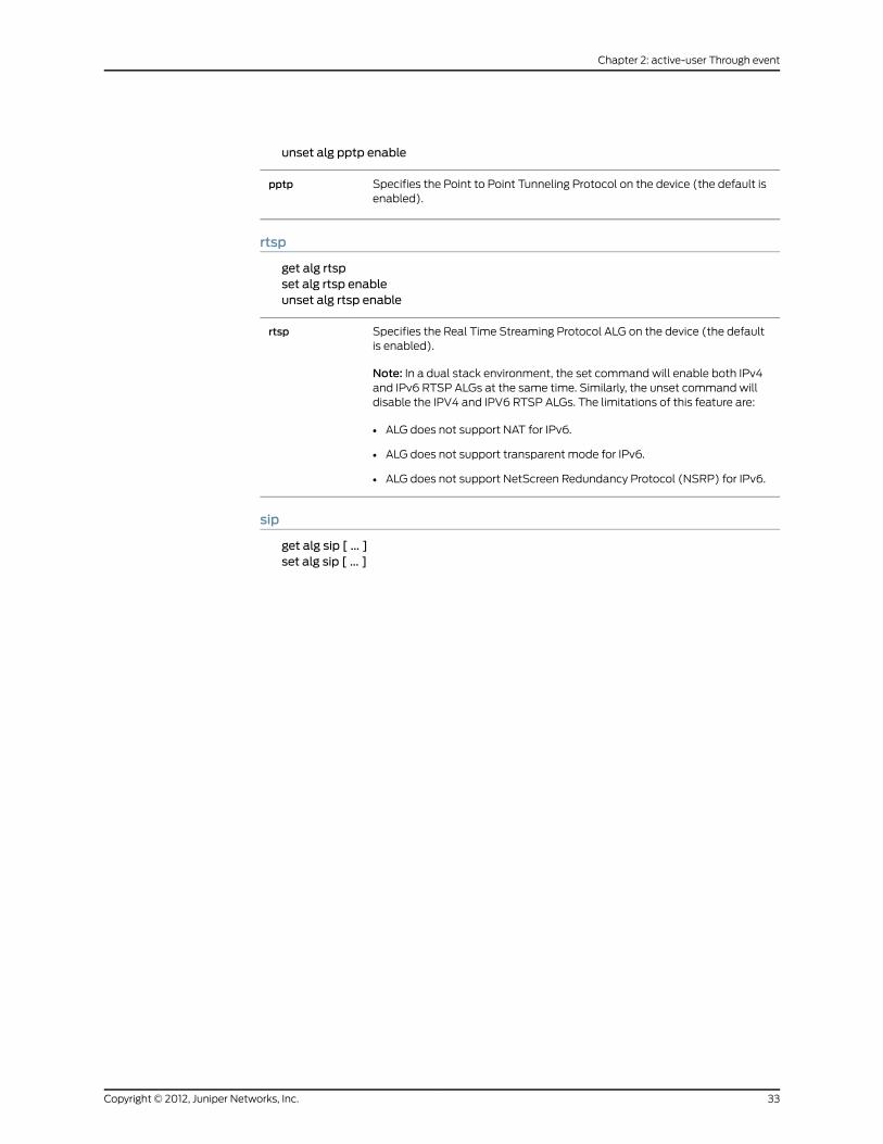
unset alg pptp enable
Specifies the Point to Point Tunneling Protocol on the device (the default isenabled).
pptp
rtsp
get alg rtspset alg rtsp enableunset alg rtsp enable
Specifies the Real Time Streaming Protocol ALG on the device (the defaultis enabled).
Note: In a dual stack environment, the set command will enable both IPv4and IPv6 RTSP ALGs at the same time. Similarly, the unset command willdisable the IPV4 and IPV6 RTSP ALGs. The limitations of this feature are:
• ALG does not support NAT for IPv6.
• ALG does not support transparent mode for IPv6.
• ALG does not support NetScreen Redundancy Protocol (NSRP) for IPv6.
rtsp
sip
get alg sip [ ... ]set alg sip [ ... ]
33Copyright © 2012, Juniper Networks, Inc.
Chapter 2: active-user Through event

unset alg sip [ ... ]
Specifies the Session Initiation Protocol ALG on the device.
• app-screenunknown-message—Specifies how unidentified messages arehandled. The default is to drop unknown messages.
• nat—Specifies that unknown messages be allowed to pass even if thesession is in NAT mode.
• route—Specifies that unknown messages be allowed to pass even if thesession is in route mode. (Sessions in transparent mode are treated asroute mode.)
• call—Displays the number of active calls. The maximum number of callspossible on a security device depends on the platform type. For moreinformation, see the datasheet for your security device.
• enable enables and disables the SIP ALG on the device (the default isenabled).
• media-inactivity-timeout—Specifies how long pinholes and sessionsopened for media are kept alive in the absence of activity. The default is120 seconds; minimum is 10 seconds, maximum is 2550 seconds.
• protect deny—Specifies that repeat SIP INVITE requests be denied to aproxy server that denied the initial request.
• dst-ip—Specifies the IP address of the proxy server.
• ipv6—Specifies the IPv6 address of the proxy server.
• timeout—Specifies the time in seconds the proxy server denies repeatedSIP messages before it begins accepting them again. The default is 5seconds; the range is 1 to 3600 seconds.
• setting—Displays the inactivity timeout parameters for SIP signaling andmedia, and the destination address of a SIP proxy server protected fromrepeat SIP INVITE requests from the proxy server initially rejected.
• signaling-inactivity-timeout—Configures or removes the maximum lengthof time in seconds a call can remain active without any SIP signaling traffic.Each time a SIP signaling message occurs within a call, this timeout resets.The default setting is 43200 seconds (12 hours); minimum is 10, maximumis 65535.
sip
sql
get alg sqlset alg sql enableunset alg sql enable
Specifies the SQL ALG on the device (the default is enabled).sql
sunrpc
get alg sunrpcset alg sunrpc enableunset alg sunrpc enable
Specifies the Sun Remote Procedure Call ALG on the device (the default isenabled).
sunrpc
Copyright © 2012, Juniper Networks, Inc.34
IPv6 Command Descriptions

alias
Use the alias commands to create, remove, or list aliases. An alias is a named variable
containing the initial characters of a CLI command. After creating an alias, you can use
it to execute the represented command.
Syntax
get
get alias
set
set alias name_str string
Keywords and Variables
Variables
The name of the CLI command alias.name_str
The CLI command to which you assign the alias.string
Example: The following commands create an alias representing the get interfaceethernet1/1 command, then execute the command using the alias:
set alias int_1 "get interface ethernet1/1"int_1
all
Use the all command to return all configuration settings to the factory default values.
Syntax
unset all
Keywords and Variables
None.
Example
In the following example, you reset the device to its factory default settings and reset
the device.
1. Execute the unset all command.
unset all
The following prompt appears: “Erase all system config, are you sure y / [n]?”
2. Press the Y key. This action returns the system configuration to the factory default
settings.
35Copyright © 2012, Juniper Networks, Inc.
Chapter 2: active-user Through event

3. Execute the reset command.
reset
The following prompt appears: “Configuration modified, save? [y] / n”
4. Press theN key. This action generates the following prompt: “System reset, are you
sure? y / [n] n”
5. Press theY key. This action restarts the system. The device now has its original factory
default settings.
arp
Use thearpcommands to create, remove, or list interface entries in the Address Resolution
Protocol (ARP) table of the security device.
Syntax
clear
clear [ cluster ] arp [ ip_addr | all ]
get
get arp [ all | asic id_num ]
set
set arp{ip_addr mac_addr interface |age number |always-on-dest}
Keywords and Variables
Variables
set arp ip_addr mac_addr interface
The IP address for the interface in the ARP table entry.ip_addr
The MAC address for the interface in the ARP table entry.mac_addr
The name of the ARP interface in the ARP table entry. For more information,see “Interfaces” on page 355.
interface
all
get arp all
Lists all current ARP entries for every existing vsys.age
Copyright © 2012, Juniper Networks, Inc.36
IPv6 Command Descriptions

asic
get asic id_num
Lists all current ARP entries for every a specified ASIC chip (id_num).asic
age
set arp age number
Sets the age-out value (in seconds) for ARP entries.age
always-on-dest
set arp always-on-dest
Directs the security device to send an ARP request for any incoming packetwith a heading containing a MAC address not yet listed in the device’s MACaddress table. This may be necessary when packets originate from serverload-balancing (SLB) switches or from devices using the Hot Standby RouterProtocol/Virtual Router Redundancy Protocol (HSRP/VRRP).
always-on-dest
cluster
clear [ cluster ] arp
Propagates the clear operation to all other devices in an NSRP cluster.cluster
asic
Use the asic commands to display the configuration details, functions, counters, and
packet flow process of a packet processing unit (PPU) in an Application-Specific
Integrated Circuit (ASIC) used in high-end platforms.
Syntax
get
get asic{mapping |ppu{configuration |defrag |dest-mac-check { drop-counter | status } |functions |ha-idp-fwd |idp |ipv6 { all | flow | parser | tunnel } |syn-cookie { [counter] | white-list ip-addr }tcp-3way-check |}
37Copyright © 2012, Juniper Networks, Inc.
Chapter 2: active-user Through event

}
Keywords and Variables
mapping
get asic mapping
Identifies the number of ASICs that each series of Juniper Network securitydevices can support.
mapping
ppu
get asic ppu {...}
Specifies the programmable hardware engine called the packet processingunit (PPU) in the ASIC
• configuration—Displays the configuration details of ASIC in shared memory.
• defrag—Specifies defragmention statistics for encrypted and clear-textpackets.
• dest-mac-check—Specifies destination MAC check on a TCP SYN packet,when SYN-Cookie is detected.
• status—Indicates if the dest-mac-check feature is enabled. By default,the dest-mac-check feature is disabled in the PPU.
• drop-counter—Indicates the number of packets that are dropped as aresult of a mismatch in the destination MAC address.
• functions—Specifies the different functions of the PPU.
• ha-idp-fwd—Represents the counter statistics related to HA and IDP packetforwards.
• idp—Displays the IDP process statistics in the PPU.
• ipv6—Specifies the various type of IPV6 packet processing.
• all—Displays all packet processes supported by the security device.
• flow—Displays the packet flow statistics between the security deviceand the host
• parser—Classifies the incoming packet as TCP or UDP.
• tunnel—Specifies about the packet flowing in and out of the tunnel. Inaddition, the command also displays the details of all syn cookies triggedwhen the packet flows through the tunnel.
• syn-cookie [counter]—Displays the process statistics of SYN-Cookies inthe PPU.
• white-list ip-addr—Displays a message to indicate if the specified IPaddress appears in the white-list. If the IP address is present, it alsodisplays the time, in seconds, after which each IP address ages out fromthe whitelist.
• tcp-3way-check—Indicates the output of a TCP-3way-check operationconducted to establish a authenticated communication channel betweenendpoints.
ppu
attack
Use the attack commands to view and define attack objects, attack object groups, and
the attack object database server settings.
Copyright © 2012, Juniper Networks, Inc.38
IPv6 Command Descriptions

NOTE: This command is available only if advancedmode is installed on thedevice.
Syntax
get
get attack[name_str |anomaly [ sort-by { id | name } ] |db |disable [ sort-by { def-type | id | name | type } ] |group [ name_str | sort-by { def-type | name } ] |id id_num |signature sort-by { def-type | id | name } |sort-by { def-type | id | name | type }]
set
set attack{CS:name_str{aim-chat-room-desc |aim-chat-room-name |aim-get-file |aim-nick-name |aim-put-file |aim-screen-name |dns-cname |ftp-command |ftp-password |ftp-pathname |ftp-username |gnutella-http-get-filename |http-authorization |http-header-user-agent |http-request |http-status |http-text-html |http-url |http-url-parsed |http-url-variable-parsed |imap-authenticate |imap-login |imap-mailbox |imap-user |msn-display-name |msn-get-file |msn-put-file |msn-sign-in-name |pop3-auth |
39Copyright © 2012, Juniper Networks, Inc.
Chapter 2: active-user Through event

pop3-header-from |pop3-header-line |pop3-header-subject |pop3-header-to |pop3-mime-content-filename |pop3-user |smb-account-name |smb-connect-path |smb-connect-service |smb-copy-filename |smb-delete-filename |smb-open-filename |smtp-from |smtp-header-from |smtp-header-linesmtp-header-subjectsmtp-header-to |smtp-mime-content-filename |smtp-rcpt |stream256 |ymsg-alias |ymsg-chatroom-message |ymsg-chatroom-name |ymsg-nickname |ymsg-p2p-get-filename-url |ymsg-p2p-put-filename-url |ymsg-user-name}[ not ] stringseverity { info | low | medium | high | critical } |
db{mode { notification | update } |schedule{daily hh:mm |monthly number hh:mm |weekly day hh:mm} |
server url_strsigpack { base | client | server | worm }} |
disable name_str |group name_str1 [ add name_str2 ] |}
Keywords and Variables
Variables
get attack name_strset attack name_str aim-chat-room-desc string severity string…set attack name_str ymsg-user-name string severity string
Copyright © 2012, Juniper Networks, Inc.40
IPv6 Command Descriptions

unset attack name_str
Defines the attack-object name. If it is a user-defined attack, it must beprefaced with CS:
Specifies one of the following contexts for Deep Inspection (DI) to search anddefines the signature string for which the DI module searches:
• aim-chat-room-desc string
…
• ymsg-user-name string
severity—Defines the severity level of the attack. You can specify any of thefollowing levels: info, low, medium, high, critical.
name_str
NOTE: For a complete list of contexts that you can specify when creatingyour own attack objects, see Volume 4: Attack Detection and DefenseMechanisms in the Concepts & Examples ScreenOS Reference Guide.
Example:The following command creates an attack object for FTP namedCS:rootuser,specifies its context as ftp-username, defines its signature as root, and specifies its
severity level as high:
set attack CS:rootuser ftp-username root severity high
anomaly
get attack anomaly [ sort-by { id | name } ]
Specifies the attack object as an anomaly.anomaly
Indicates the organization for the display of protocol anomalies in the localdatabase—either numerically by id or alphabetically by name.
sort-by
attack
get attack
Displays all attack objects currently stored in the local database, displaying—inalphabetical order—first user-defined attacks (if any) and then predefinedattacks.
attack
db
get attack dbset attack dbmode { notification | update }set attack db schedule { daily hh:mm | monthly number hh:mm | weekly day hh:mm}set attack db server url_str
41Copyright © 2012, Juniper Networks, Inc.
Chapter 2: active-user Through event

unset attack db {mode | schedule | server | sigpack }
Specifies the attack-object database server. On security devices that supportvirtual systems, you must set this command at the root level.
mode—Selects either notification or update as the mode for checking andupdating the attack-object database.
• notification—Automatically checks the attack-object database server atuser-defined times and notifies the admin if the database on the server ismore recent than the one on the security device. (If the data on the serveris more recent, a notice appears on the WebUI main page and in the CLIafter you log into the device.)
• update—Automatically checks the attack object database server atuser-defined times and automatically updates the database on the securitydevice if it determines that the database on the server is more recent thanthe one on the security device.
Unsetting this command stops the security device from automaticallychecking the server.
schedule string—Sets the time for automatically checking the attack-objectdatabase server and updating the attack object database on the securitydevice. You can set a daily, monthly, or weekly schedule.
serverurl_str—Defines the URL of the attack-object database server. ScreenOSprovides four predefined DI signature packs: base, server, client, and worm.The base signature pack is the default. If you do not specify a signature packas shown in Example 1, then the basic signature pack is retrieved.
Unsetting the attack object database server retrieves the basic signature packonly. If you run the exec attack-db update command with a server URL setto null, then the base signature pack from the following URL is loaded:https//services.netscreen.com/restricted/sigupdates
sigpack—Specifies the predefined signature packs. To use a signature pack,you must purchase a DI database license key and download the appropriatepackage for your environment from the Juniper Networks Website.
ScreenOS provides four predefined DI signature packs:
• base—Includes a sample of worm, client-to-server, and server-to-clientsignatures for Internet-facing protocols and services, such as HTTP, DNS,FTP, SMTP, POP3, IMAP, NetBIOS/SMB, MS-RPC, P2P, and IM (AIM, YMSG,MSN, and IRC).
• server—Focuses on protecting a server farm. It includes a comprehensiveset of server-oriented protocols, such as HTTP, DNS, FTP, SMTP, IMAP,MS-SQL, and LDAP. Also includes worm signatures that target servers.
• client—Focuses on protecting users from getting malware, Trojans, and soon while surfing the Internet. Includes a comprehensive set of client-orientedprotocols, such as HTTP, DNS, FTP, IMAP, POP3, P2P, and IM (AIM, YMSG,MSN, and IRC). Also includes worm signatures that target clients.
• worm—Includes stream signatures and primarily focuses on providingcomprehensive worm protection. Detects server-to-client andclient-to-server worm attacks for all protocols.
The base signature pack is the default. If you do not specify a signaturepack as shown in Example 1, then the base signature pack is retrieved.
Note: Your security device allows you to load one signature pack at a time.
The unset attack db sigpack command followed by the exec attack-dbupdate command retrieves the basic signature pack.
db
Copyright © 2012, Juniper Networks, Inc.42
IPv6 Command Descriptions

Example 1:The following command configures your security device to retrieve the server
signature pack:
set attack db sigpack server
Example 2:Use the following URL strings to configure your security device to retrieve
the base, server, client, or worm signature packs, respectively:
set attack db server http://services.netscreen.com/restricted/sigupdatesset attack db server http://services.netscreen.com/restricted/sigupdates/serverset attack db server http://services.netscreen.com/restricted/sigupdates/clientset attack db server http://services.netscreen.com/restricted/sigupdates/worm
Example 3: The following commands define the URL of the attack-object database
server and set a schedule to check the server automatically and then notify the security
device admin when the database on the server is more recent than that on the security
device:
set attack db server http://www.juniper.net/attacksset attack db schedule daily 07:00set attack dbmode notification
disable
set attack disable name_strunset attack disable name_strget attack disableget attack disable sort-by [ sort-by { def-type | id | name | type } ]
Disables the specified predefined attack object or a list of all disabled attackobjects. You can organize the display of the list by one of the followingattributes:
• def-type —Organizes the disabled attack-object display by anomaly andthen by signature, and then within each of these two categories,alphabetically by protocol.
• id—Organizes the disabled attack-object display numerically by ID number.
• name—Organizes the disabled attack-object display alphabetically byattack name.
• type —Organizes the disabled attack-object display alphabetically byanomaly and then by signature.
disable
group
get attack group [ sort-by { def-type | name } ]set attack group name_str1 [ add name_str2 ]unset attack group name_str1 [ remove name_str2 ]
Specifies an attack object group.group
43Copyright © 2012, Juniper Networks, Inc.
Chapter 2: active-user Through event

Indicates the organization for the display of attack groups from the localdatabase:
• def-type—Organizes the attack group display by the definition type of theattack group, displaying first the predefined attack groups in alphabeticalorder and then the user-defined groups.
• name—Organizes the attack group display alphabetically by attack groupnames.
name_str—Specifies a name for the creation, deletion, or modification ofan attack group. The keywords add and remove indicate that an attack isbeing added to or is being removed from the specified group.
sort-by
Example: The following command displays all the attack groups on the security device
by name in alphabetical order:
get attack group sort-by name
id
get attack id id_num
Specifies the ID number of an attack object in the local database.id
Example: The following command displays the attack object with ID number 500 in the
security device:
get attack id 500
not
set attack CS:name_str not string1 severity string2
Defines as an attack object anything in the specified context except theuser-defined attack pattern.
not
Example: The following command defines the attack object named CS:badlogin as
anything except the permitted FTP username jj2345with a medium-level severity:
set attack CS:badlogin ftp-username not jj2345 severity medium
signature
get attack signature [ sort-by { def-type | id | name } ]
Displays stateful signature attack objects currently stored in the localdatabase.
• sort-by—Specifies the organizational display of attack objects by one ofthe following attributes:
• def-type—Organizes the stateful signature attack object display by thedefinition type of the attack object, displaying first the predefined attackobjects in alphabetical order and then the user-defined objects.
• id—Organizes the stateful signature attack object display numericallyby ID number.
• name—Organizes the stateful signature attack object displayalphabetically by attack name.
signature
Copyright © 2012, Juniper Networks, Inc.44
IPv6 Command Descriptions

Example: The following command displays signature attack objects on the security
device alphabetically by name:
get attack signature sort-by name
sort-by
get attack sort-by { def-type | id | name | type }
Specifies the organizational display of attack objects in the local databaseby one of the following attributes:
• def-type—Organizes the attack object display by the definition type of theattack object, displaying first the predefined attack objects in alphabeticalorder and then the user-defined objects.
• id—Organizes the attack object display numerically by ID number.
• name—Organizes the attack object display alphabetically by attack name.
• type—Organizes the attack object display alphabetically by protocol type,and then within each protocol type by attack name.
sort-by
Example: The following command displays all attack objects in the security device
organized numerically:
get attack sort-by id
auth
Use the auth commands to specify a user authentication method.
The four available methods include:
• A built-in database
• A RADIUS server
• SecurID
• Lightweight Directory Access Protocol (LDAP)
• Terminal Access Controller Access Control System+ (TACACS+)
NOTE: If the security device uses SecurID to authenticate users, andcommunication problems occur with the ACE server, clear the currentSecurID shared secret from the device (and the server) by executing theclear node_secret command.
Syntax
clear
clear [ cluster ] auth[history |queue |
45Copyright © 2012, Juniper Networks, Inc.
Chapter 2: active-user Through event

statistics |table [ id id_num | ip ip_addr ]]
get
get auth[banner |history [ id id_num | ip ip_addr ] |queue |settings |table [ id id_num | ip ip_addr ]]
set
set auth{banner { ftp | http | telnet } { fail string | login string | success string }default auth server name_str |radius accounting{action cleanup-session |port port_num} |
}
Arguments
banner
get auth bannerset auth banner { ftp | http | telnet }unset auth banner { ftp | http | telnet }
Defines or displays firewall banners. The security device uses these bannersto report success or failure of login requests.
• ftp—Reports on the success or failure of FTP login requests.
• http—Reports on the success or failure of HTTP login requests.
• telnet—Reports on the success or failure of Telnet login requests.
• fail string—Specifies a message string to display a login attempt fails.
• login string—Specifies a message string to display when a login attemptoccurs.
• success string—Specifies a message string to display when a loginattempt is successful.
banner
Example: The following command defines a banner for a failed FTP login attempt:
Copyright © 2012, Juniper Networks, Inc.46
IPv6 Command Descriptions

set auth banner ftp fail "FTP login attempt failed"
cluster
clear [ cluster ] auth [ ... ]
Propagates the clear operation to all other devices in an NSRP cluster.cluster
default
set auth default auth server name_strunset auth default auth server
Specifies a default firewall authentication server (name_str). The securitydevice uses this server when a security policy does not explicitly identify aparticular authentication server.
default authserver
Example: The following command identifies the default authentication server
(Auth_Server):
set auth default auth server Auth_Server
history
clear [ cluster ] auth historyget auth history [ id id_num | ip ip_addr ]
Clears or displays the history of users authenticated through the securitydevice.
history
queue
clear [ cluster ] auth queueget auth queue
Clears or displays the internal user authentication queue.queue
radius accounting
set auth radius accounting action cleanup-sessionset auth radius accounting port port_numunset auth radius accounting action cleanup-session
47Copyright © 2012, Juniper Networks, Inc.
Chapter 2: active-user Through event

unset auth radius accounting port
This feature allows any organization that owns or controls a RADIUS serverto track RADIUS session information for billing, monitoring, or other purposes.For example, a RADIUS server might need to record information about whenauthorized sessions begin, when they end, the number of bytes or packetsexchanged during each session, and so on. Such tracking is generally referredto as RADIUS accounting. Each RADIUS accounting session begins when theRADIUS server receives an Accounting-Start message and ends when itreceives an Accounting-Stop message.
RADIUS accounting allows the device to monitor and manage authorizedsessions. For example, a device might clear out zombie sessions when itreceives an Accounting-Stop message from an external RADIUS client. Thiscould prevent misuse of wireless calls if a subsequent user gets a previoususer’s assigned IP address and attempts to use the previous user’s session.
The port (port_num) setting specifies the port through which the devicereceives Accounting-Start and Accounting-Stop messages. In addition, thecleanup-session feature allows the device to clear out zombie sessions whenit receives an Accounting-Stop message from an external RADIUS client. Thisfeature prevents misuse of wireless calls if subsequent users get the sameassigned IP address and happen to use the previous user’s session in thedevice.
Note: This feature is not supported on the vsys level and is for the root levelonly. This feature is only for clearing zombie sessions. Enablement is notrequired for the security device to support RADIUS accounting whilecommunicating with the RADIUS server.
radiusaccounting
settings
get auth settings
Displays default user authentication server settings. (This option yields thesame display as the get auth command.
settings
statistics
clear auth statisticsget auth statistics
Clears or displays authentication run-time statistics.statistics
table
clear [ cluster ] auth table [ id id_num | ip ip_addr ]
Copyright © 2012, Juniper Networks, Inc.48
IPv6 Command Descriptions

get auth table [ id id_num | ip ip_addr ]
Clears entries from the user authentication table (thus forcingreauthentication), or displays such entries. Entries in the user authenticationtable can represent:
• Users currently authenticated
• Users currently undergoing authentication
• Users denied authentication
Without parameters (described below), the table option clears or displaysall table entries.
• id id_num—Clears or displays a particular entry by ID (id_num).
• ip ip_addr—Clears or displays all entries with a common source IP address(ip_addr).
table
Examples: The following command clears entry 7 from the user authentication table:
clear auth table id 7
The following command displays authentication details from a table entry with source
IP 10.1.10.10:
get auth table ip 10.1.10.10
auth-server
Use the auth-server commands to configure the security device for user authentication
with a specified authentication server. Admins, policies, VPN tunnel specifications, and
XAuth configurations use these server specifications to gain access to the appropriate
resources.
Syntax
get
get auth-server{string |all |id id_num}
set
set auth-server name_str{account-type { [ 802.1X ] [ admin ] | [ auth ] [ l2tp ] [ xauth ] } |backup1 { ip_addr | name_str } |backup2 { ip_addr | name_str } |fail-over revert-interval number |forced-timeout |id id_num |ldap{
49Copyright © 2012, Juniper Networks, Inc.
Chapter 2: active-user Through event
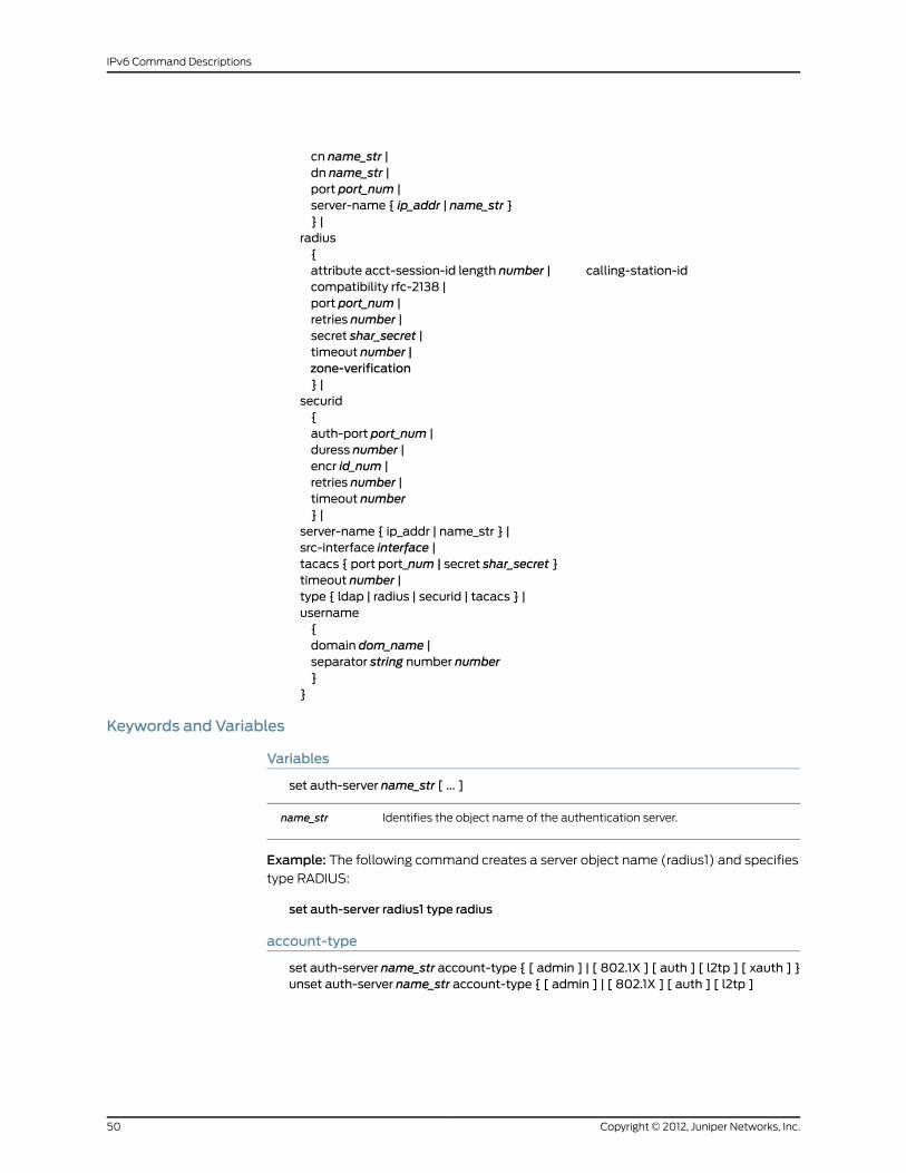
cn name_str |dn name_str |port port_num |server-name { ip_addr | name_str }} |
radius{attribute acct-session-id length number | calling-station-idcompatibility rfc-2138 |port port_num |retries number |secret shar_secret |timeout number |zone-verification} |
securid{auth-port port_num |duress number |encr id_num |retries number |timeout number} |
server-name { ip_addr | name_str } |src-interface interface |tacacs { port port_num | secret shar_secret }timeout number |type { ldap | radius | securid | tacacs } |username{domain dom_name |separator string number number}
}
Keywords and Variables
Variables
set auth-server name_str [ ... ]
Identifies the object name of the authentication server.name_str
Example: The following command creates a server object name (radius1) and specifies
type RADIUS:
set auth-server radius1 type radius
account-type
set auth-server name_str account-type { [ admin ] | [ 802.1X ] [ auth ] [ l2tp ] [ xauth ] }unset auth-server name_str account-type { [ admin ] | [ 802.1X ] [ auth ] [ l2tp ]
Copyright © 2012, Juniper Networks, Inc.50
IPv6 Command Descriptions

[ xauth ] }
Specifies the types of users authenticated by the server (name_str).
• 802.1X—Specifies that the server configuration uses only 802.1x protocolfor wireless connectivity between the device and the authentication server.
• admin—Specifies admin users.
• auth—Specifies authentication users.
• l2tp—Specifies Layer 2 Tunneling Protocol (L2TP) users.
• xauth—Specifies XAuth users.
You can define a user as a single user type—an admin user, an authenticationuser, an L2TP user, or an XAuth user. You can combine auth, L2TP, andXAuth user types to create an auth-L2TP user, an auth-XAuth user, anL2TP-XAuth user, or an auth-L2TP-XAuth user. You cannot combine anadmin user with another user type.
Specify admin users only for TACACS+ authentication.
account-type
all
get auth-server all
Specifies all configured authentication servers.all
backup1 | backup2
set auth-server name_str { backup1 { ip_addr | name_str } | backup2 { ip_addr | name_str} }unset auth-server name_str { backup1 | backup2 }
The IP address or DNS name of the primary backup authentication server foran LDAP, RADIUS, SecurID, or TACACS+ server type.
backup1
The IP address or DNS name of the secondary backup authentication serverfor an LDAP, RADIUS, or TACACS+ server type. SecurID does not supportmore than one backup server.
backup2
Example:With the following commands, you first create a RADIUS authentication server
object named radius1 at IPv6 address 2ffe::2. This server stores authentication user
accounts. Then you define a primary backup server at IPv4 address 10.1.1.51 and a
secondary backup server at IPv4 address 10.1.1.52.
set auth-server radius1 server-name 2ffe::2set auth-server radius1 type radiusset auth-server radius1 account-type authset auth-server radius1 backup1 10.1.1.51set auth-server radius1 backup2 10.1.1.52
fail-over
set auth-server name_str fail-over revert-interval number |
51Copyright © 2012, Juniper Networks, Inc.
Chapter 2: active-user Through event

unset auth-server name_str fail-over revert-interval
This feature specifies the interval (expressed in seconds) that must pass afteran authentication attempt, before the device attempts authentication throughbackup authentication servers. When an authentication request sent to aprimary server fails, the security device tries the backup servers. Ifauthentication via a backup server is successful, and the revert-interval timeinterval has elapsed, the device sends subsequent authentication requeststo the backup server. Otherwise, it resumes sending the requests to the primaryserver. The range is 0 seconds (disabled) to 86400 seconds.
This feature applies to RADIUS, LDAP, and TACACS+ servers only.
fail-over
forced-timeout
set auth-server forced-timeout number|unset auth-server forced-timeout
Specifies the time, in minutes, after which access for the authenticated useris terminated. The auth table entry for the user is removed, as are all associatedsessions for the auth table entry. Forced timeout behavior is independent ofidle timeout setting. The default is 0 (disabled), the range is 0 to 10000 (6.9days). Compare “timeout” on page 55.
forced-timeout
id
get auth-server id id_numset auth-server name_str id id_numunset auth-server id id_num
The user-defined identification number (id_num) of the authentication server.If you do not define an ID number, the security device creates oneautomatically.
id
Example: The following command creates an identification number (200) for the
authentication server radius1:
set auth-server radius1 id 200
ldap
set auth-server name_str ldap{ cn name_str | dn name_str | port port_num | server-name name_str }
Configures the security device to use an LDAP server for authentication.
• cn name_str—The Common Name identifier used by the LDAP server toidentify the individual entered in a LDAP server. For example, an entry of“uid” means “ user ID” and “ cn” means “ common name” .
• dn name_str—The Distinguished Name identifier is the path used by theLDAP server before using the common name identifier to search for aspecific entry. (For example, c=us;o=juniper, where “c” stands for “ country”, and “ o” for “ organization” .).
• port port_num—Specifies the port number to use for communication withthe LDAP server. The default port number for LDAP is 389.
• server-name name_str—The IPv4 address, IPv6 address, or DNS name ofthe LDAP server.
ldap
Copyright © 2012, Juniper Networks, Inc.52
IPv6 Command Descriptions

Example: For an example of these options, see “Defining an LDAP Server Object” on
page 57.
radius
set auth-server name_str radius { ... }unset auth-server name_str radius { port | timeout }
Configures the security device to use a RADIUS server for authentication.
• attribute—Specifies settings for RADIUS accounting.
Each time an XAuth user connects to the device and the deviceauthenticates the user, the device establishes a new acct-session-id, whichidentifies the accounting session. The accounting session lasts betweenthe time the device sends the RADIUS server an Accounting-Start message,and the time it sends an Accounting-Stop message. To identify the user,each RADIUS access or request message contains the calling-station-id.
• acct-session-id length number—The length of the account-session-idin bytes. The acct-session-id uniquely identifies the accounting session.The default length of this value is 11 bytes. The number setting is foraccommodating some RADIUS servers, which may have problems withthe default length. You can set the length of acct-session-id from 6 bytesto 10 bytes, inclusive. To restore the default setting, execute the followingcommand:unset auth-server name_str radius attribute acct-session-id length
• compatibility rfc-2138—Makes RADIUS accounting comply with RFC 2138,as compared with RFC 2865. For operations where RFC 2865 (the mostrecent standard) and RFC 2138 are mutually exclusive, the command worksin accordance with RFC 2138, instead of RFC 2865. In cases where thebehavior is additive, the command works compatibly with both RFC 2865and RFC 2138.
• port port_num—The port number on a RADIUS server to which the securitydevice sends authentication requests. The default port number is 1645.You can change the default port number to any number between 1024 and65535, inclusive.
• retries number—The number of retries sent to the RADIUS server beforeRADIUS authentication fails. The range is 1 to 20 retries.
• secret shar_secret—Specifies the RADIUS shared secret (shar_secret) thatis shared between the security device and the RADIUS server. The securitydevice uses this secret to encrypt the user’s password that it sends to theRADIUS server.
• timeout number—The interval (in seconds) that the security device waitsbefore sending another authentication request to the RADIUS server if theprevious request does not elicit a response. The default is three seconds.
radius
Example: For an example of these options, see “Defining a RADIUS Server Object” on
page 56.
53Copyright © 2012, Juniper Networks, Inc.
Chapter 2: active-user Through event

securid
set auth-server name_str securid { auth-port port_num | duress number | encr id_num |retries number | timeout number }
Configures the security device to use a SecurID server for authentication.
• auth-port port_num—Specifies the port number to use for communicationswith the SecurID server. The default SecurID port number is 5500.
• duress {0 | 1 }—If the SecurID server is licensed to use duress mode, a valueof 0 deactivates it and 1 activates it. When duress mode is activated, a usercan enter a special duress PIN number when logging in. The security deviceallows the login, but sends a signal to the SecurID server, indicating thatsomeone is forcing the user to login against his or her will. The SecurID authserver blocks further login attempts by that user until he or she contactsthe SecurID server admin.
• encr {0 | 1 }—Specifies the encryption algorithm for SecurID network traffic.A value of0 specifies SDI, and 1 specifies DES. We recommend the defaultencryption type DES.
• retries number—Specifies the number of retries between requests forauthentication.
• timeoutnumber—Specifies the length of time (in seconds) that the securitydevice waits between authentication retry attempts.
securid
Example: For an example of these options, see “Defining a SecurID Server Object” on
page 57.
server-name
set auth-server name_str server-name { ip_addr | name_str }
The IPv4 address, IPv6 address, or DNS name of the authentication server.server-name
src-interface
set auth-server name_str src_interface interface
Instructs the device to transmit authentication requests (RADIUS or SecurID)through the specified interface.
src-interface
timeout
set auth-server name_str timeout numberunset auth-server name_str timeout
Specifies how many minutes must elapse after termination of anauthentication, L2TP, or XAuth user’s last session before the user needs toreauthenticate. The default timeout value is 10 minutes, and the maximumsetting is 255 minutes. If the user initiates a new session before the countdownreaches the timeout threshold, he does not have to reauthenticate himselfand the timeout countdown resets.
If the user is an admin user, this setting specifies how many minutes ofinactivity must elapse before the security device times out and closes anadmin session. The default is 10 minutes and the maximum is 1000 minutes.
timeout
Copyright © 2012, Juniper Networks, Inc.54
IPv6 Command Descriptions

Example:For an example of this option, see “Defining a SecurID Server Object” on page 57.
tacacs
set auth-server name_str tacacs { ... }unset auth-server name_str tacacs { port | secret }
Configures the security device to use a TACACS+ server for authentication.
• port port_num—The TCP port on a TACACS+ server to which the securitydevice sends authentication requests. The default port number is 49. Youcan change the default port number to any number between 1024 and32767, inclusive.
• secret shar_secret—Specifies the TACACS+ shared secret (shar_secret)that is shared between the security device and the TACACS+ server. Thesecurity device uses this secret to encrypt the user’s password that it sendsto the TACACS+ server.
tacacs
timeout
set auth-server name_str timeout numberunset auth-server name_str timeout
Specifies how many minutes must elapse after the termination of anauthentication, L2TP, or XAuth user’s last session before the user needs toreauthenticate. The default timeout value is 10 minutes, and the maximumsetting is 255 minutes. If the user initiates a new session before the countdownreaches the timeout threshold, the user does not have to reauthenticate andthe timeout countdown resets.
If the user is an admin user, this setting specifies how many minutes ofinactivity must elapse before the security device times out and closes anadmin session. The default is 10 minutes and the maximum is 1000 minutes.Compare with “forced-timeout” on page 52.
timeout
Example:For an example of this option, see “Defining a SecurID Server Object” on page 57.
type
set auth-server name_str type { ldap | radius | securid }
Specifies the type of authentication server—LDAP, SecurID or RADIUS. Theunset command sets type to radius.
type
Example:For an example of this option, see “Defining a RADIUS Server Object” on page 56.
username
set auth-server name_str username domain dom_nameset auth-server name_str username separator string number numberunset auth-server name_str username domain
55Copyright © 2012, Juniper Networks, Inc.
Chapter 2: active-user Through event

unset auth-server name_str username separator
Specifies a domain name for a particular auth server, or a portion of ausername from which to strip characters. If you specify a domain name forthe auth server, it must be present in the username during authentication.
The device uses a separator character to identify where stripping occurs.Stripping removes all characters to the right of each instance of the specifiedcharacter, plus the character itself. The device starts with the right mostseparator character.
The parameters for this feature are as follows:
• string is the character separator.
• number is the number of character separator instances with which toperform the character stripping.
If the specified number of separator characters (number) exceeds theactual number of separator characters in the username, the commandstops stripping at the last available separator character.
Note: The device performs domain-name matching before stripping.
username
Example: In the following example, you strip characters to the right of two instances of
a separator character in a username.
• Auth server name Acme_Server
• Username bob@[email protected]
• Separator is @
• Number of instances 2
set auth-server Acme_Server username separator bob@[email protected] number 2
The resulting username is bob.
zone-verification
set auth-server name_str radius zone-verificationunset auth-server name_str radius zone-verification
Verifies the zones the user is a member of and the zone configured on theport.
An authentication check can include support for zone verification. Thiscommand requires the specified RADIUS server to support RADIUS VSAenhancement. Authentication is allowed only if the zone configured on theport is a zone that a user is a member of.
In your dictionary file, add an attribute name of Zone_Verification as a stringattribute type. The vendor ID is 3224, and the attribute number is 10.
zone-verification
Example:For an example of this option, see “Defining a RADIUS Server Object” on page 56.
Defining a RADIUS Server Object
The following commands define an auth-server object for a RADIUS server:
set auth-server radius1 type radius
Copyright © 2012, Juniper Networks, Inc.56
IPv6 Command Descriptions

set auth-server radius1 account-type auth l2tp xauthset auth-server radius1 server-name 10.1.1.50set auth-server radius1 backup1 10.1.1.51set auth-server radius1 backup2 10.1.1.52set auth-server radius1 radius port 4500set auth-server radius1 radius timeout 4set auth-server radius1 radius secret A56htYY97klset auth-server radius1 radius zone-verificationsave
If you are using vendor-specific attributes, you must load the netscreen.dct file on the
RADIUS server.
Defining a SecurID Server Object
The following commands define an auth-server object for a RADIUS server:
set auth-server securid1 type securidset auth-server securid1 server-name 10.1.1.100set auth-server securid1 backup1 10.1.1.110set auth-server securid1 timeout 60set auth-server securid1 account-type adminset auth-server securid1 securid retries 3set auth-server securid1 securid timeout 10set auth-server securid1 securid auth-port 15000set auth-server securid1 securid encr 1set auth-server securid1 securid duress 0save
Defining an LDAP Server Object
The following commands define an auth-server object for an LDAP server:
set auth-server ldap1 type ldapset auth-server ldap1 account-type authset auth-server ldap1 server-name 10.1.1.150set auth-server ldap1 backup1 10.1.1.151set auth-server ldap1 backup2 10.1.1.152set auth-server ldap1 timeout 40set auth-server ldap1 ldap port 15000set auth-server ldap1 ldap cn cnset auth-server ldap1 ldap dn c=us;o=juniper;ou=marketingsave
The following command lists all auth-server settings:
get auth-server all
Defining a TACACS+ Server Object
The following commands define an auth-server object for a TACACS+ server:
set auth-server tacacs1 type tacacsset auth-server tacacs1 account-type adminset auth-server tacacs1 server-name 10.1.1.50set auth-server tacacs1 backup1 10.1.1.51set auth-server tacacs1 backup2 10.1.1.52
57Copyright © 2012, Juniper Networks, Inc.
Chapter 2: active-user Through event

set auth-server tacacs1 tacacs port 1050set auth-server tacacs1 tacacs secret A56htYY97klset auth-server tacacs1 timeout 4save
chassis
Use the set chassis commands to activate the audible alarm feature or to set the normal
and severe temperature thresholds for triggering temperature alarms.
Syntax
get
get chassis
set
set chassis{audible-alarm{ all | battery | fan-failed | power-failed | temperature } |
temperature-threshold{ alarm | severe }{ celsius number | fahrenheit number }
Arguments
Enables or disables the audible alarm to announce hardware failureevents.
• all—Enables or disables the audible alarm in the event of a fanfailure, an interface module failure, a power supply failure, or atemperature increase above an admin-defined threshold.
• battery—Enables or disables the audible alarm in the event ofbattery failure.
• fan-failed—Enables or disables the audible alarm in the eventof a fan failure.
• module-failed—Enables or disables the audible alarm in theevent of an interface module failure.
• power-failed—Enables or disables the audible alarm in the eventof a power supply failure.
• temperature—Enables or disables the audible alarm if thetemperature rises above an admin-defined threshold.
audible-alarm
Defines the temperature (celsius or fahrenheit) required to triggera regular alarm or a severe alarm. A severe alarm sounds a greaterfrequency of audible alarms and generates a greater number ofevent log entries.
temperature-threshold
Copyright © 2012, Juniper Networks, Inc.58
IPv6 Command Descriptions
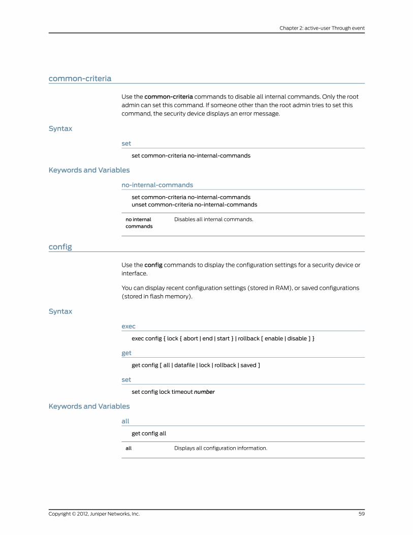
common-criteria
Use the common-criteria commands to disable all internal commands. Only the root
admin can set this command. If someone other than the root admin tries to set this
command, the security device displays an error message.
Syntax
set
set common-criteria no-internal-commands
Keywords and Variables
no-internal-commands
set common-criteria no-internal-commandsunset common-criteria no-internal-commands
Disables all internal commands.no internalcommands
config
Use the config commands to display the configuration settings for a security device or
interface.
You can display recent configuration settings (stored in RAM), or saved configurations
(stored in flash memory).
Syntax
exec
exec config { lock { abort | end | start } | rollback [ enable | disable ] }
get
get config [ all | datafile | lock | rollback | saved ]
set
set config lock timeout number
Keywords and Variables
all
get config all
Displays all configuration information.all
59Copyright © 2012, Juniper Networks, Inc.
Chapter 2: active-user Through event

datafile
get config datafile
Displays the Network and Security Manager (NSM) datafile, which resides onthe security device and contains current device configurations formattedaccording to the NSM syntax schema. ScreenOS generates the datafile fromthe current device configuration when the NSM management system queriesthe device.
datafile
lock
exec config lock startexec config lock endexec config lock abortset config lock timeout numberunset config lock timeout
Instructs the security device to lock a configuration file in memory for aspecified time interval.
• exec config lock—Locks/unlocks the configuration file in memory. You canalso abort the lockout and immediately restart the device with theconfiguration file that was previously locked in memory.
• set config lock timeout —Changes the default lockout period, which is 5minutes.
lock
rollback
exec config rollbackexec config rollback enableexec config rollback disableget config rollback
• exec config rollback Reverts the security device to the LKG(last-known-good) configuration—providing that an LKG configuration isavailable.
• enable—Enables the security device to automatically rollback to theLKG configuration in case of a problem when loading a new configuration.
• disable—Disables the automation of the configuration rollback featureon the security device. If you disable the automation of this feature, youcan still perform a configuration rollback manually using the exec configrollback command.
• get config rollback—Indicates if an LKG configuration is available forconfiguration rollback and also indicates if the automatic config rollbackfeature is enabled.
If there is an LKG configuration saved in memory, the output of thecommand displays:“$lkg$.cfg” (the name of the LKG file).
The config rollback feature is enabled if the output of the command displays“= yes” at the end of the string. For example:""$lkg$.cfg"" = yes”
If the feature is not enabled, the output displays a blank space instead of“yes” .
rollback
Copyright © 2012, Juniper Networks, Inc.60
IPv6 Command Descriptions

saved
get config saved
counter
Use the counter commands to clear or display the values contained in traffic counters.
Traffic counters provide processing information, which you can use to monitor traffic
flow. security devices maintain the following categories of counters:
• Screen counters, for monitoring firewall behavior for the entire zone or for a particular
interface
• Policy counters, for reporting the amount of traffic affected by specified policies
• Hardware counters, for monitoring hardware performance and tracking the number
of packets containing errors
• Flow counters, for monitoring the number of packets inspected at the flow level
Syntax
clear
clear [ cluster ] counter{all |ha |screen [ interface interface | zone zone ]}
get
get counter{flow | statistics[ interface interface | zone zone ] |
screen { interface interface | zone zone }policy pol_num { day | hour | minute | month | second }}
Keywords and Variables
cluster
clear [ cluster ] counter [ ... ]
Propagates the clear operation to all other devices in an NSRP cluster.cluster
Example:To clear the contents of all counters and propagate the operation to all devices
in the cluster:
61Copyright © 2012, Juniper Networks, Inc.
Chapter 2: active-user Through event

clear cluster counter all
flow
get counter flow [ ... ]
Specifies counters for packets inspected at the flow level. A flow-levelinspection examines various aspects of a packet to gauge its nature and intent.
flow
ha
clear [ cluster ] counter ha
Specifies counters for packets transmitted across a high availability (HA) linkbetween two security devices. An HA-level inspection keeps count of thenumber of packets and packet errors.
ha
interface
clear [ cluster ] counter screen interface interface
The name of the interface. Specifies counters for packets inspected at theinterface level. The inspection checks for packet errors and monitors thequantity of packets according to established threshold settings. For moreinformation, see “Interfaces” on page 355.
interface
policy
get counter policy pol_num { day | hour | minute | month | second }
Identifies a particular policy (pol_num). This allows you to monitor the amountof traffic that the policy permits.
day | hour | minute | month | second—Specifies the period of time formonitoring traffic permitted by a particular policy.
policy
screen
clear [ cluster ] counter screen [ interface interface | zone zone ]get counter screen { interface interface | zone zone }
Clears the screen counters. The interface interface parameter specifies thename of a particular interface. For more information, see “Interfaces” onpage 355.
screen
statistics
get counter statistics [ ... ]
Displays the counter statistics.statistics
Copyright © 2012, Juniper Networks, Inc.62
IPv6 Command Descriptions

zone
get counter screen zone zone
Identifies the zone and specifies counters for packets inspected at the zonelevel. The inspection checks for packet errors and monitors the quantity ofpackets according to established threshold settings. For more information,see “Interfaces” on page 355.
zone
cpu-limit
Use thecpu-limitcommands to enable and configure the CPU limit feature, which allows
you to configure a more fair distribution of CPU resources.
Before you configure CPU limit feature parameters, use must use the set cpu-limitcommand to initialize and allocate resources for the feature.
Use the get cpu-limit command to review CPU limit feature parameters configured with
the set cpu-limit commands.
Syntax
exec
exec cpu-limit mode { fair | shared }
get
get cpu-limit [ utilization ]
set
set cpu-limit[enable |fair-to-shared{automatic [ threshold number ] [ hold-down-time number ] |fair-time number |never} |
shared-to-fair threshold number [ hold-down-time number ]]
Keywords and Variables
enable
set cpu-limit enableunset cpu-limit enable
Use this command after configuring the CPU limit feature parameters toenable the feature.
enable
Example: The following command enables the CPU limit feature:
63Copyright © 2012, Juniper Networks, Inc.
Chapter 2: active-user Through event

set cpu-limit enable
fair-to-shared
set cpu-limit fair-to-shared automatic [ threshold number ] [ hold-down-time number ]set cpu-limit fair-to-shared fair-time numberset cpu-limit fair-to-shared neverunset cpu-limit fair-to-shared { ... }
Configures parameters to determine when the security device transitions fromfair to shared mode.
• automatic—Specifies that the security device automatically transitions toshared mode when the flow CPU utilization percentage falls below a specificthreshold.
• Optionally, specify the threshold value, which is from 0 through 100percent. If you do not specify a threshold value, the threshold is the samevalue as the shared-to-fair threshold.
• Optionally, specify a hold-down time, which is the minimum amount oftime that the flow CPU utilization percentage is below the flow CPUutilization percentage threshold. Valid value range is 0 through 1800seconds (30 minutes). The default value is 20 seconds.
• fair-time—Specifies the amount of time the security device is in fair modebefore going back to shared mode. The value range is 5 through7200 seconds (2 hours). The default value is 30 seconds.
• never—Specifies that the security device never transitions from fair toshared mode. You can manually force the security device into shared modeby using the exec cpu-limit mode shared command.
fair-to-shared
The following command configures the security device to remain in fair mode for 3600
seconds (1 hour).
set cpu-limit fair-to-shared fair-time 3600
mode
exec cpu-limit mode { fair | shared }
Forces the security device into fair mode.fair
Forces the security device into shared mode.shared
Depending on network conditions and the configured CPU limit feature parameters, the
security device might transition from the mode specified by this command. Use the execcpu-limit mode shared command to return to shared mode in the following situations:
• You configured the security device to never transition from fair to shared mode.
• You want the security device to return to shared mode before the specified fair-time
value or hold-down time elapses.
If you configured a hold-down time with the set cpu-limit shared-to-fair command, use
the exec cpu-limit mode fair command if you want the security device to return to fair
mode before the hold-down time elapses.
Copyright © 2012, Juniper Networks, Inc.64
IPv6 Command Descriptions

The following command forces the security device into fair mode:
exec cpu-limit mode fair
The following command forces the security device into shared mode:
exec cpu-limit mode shared
shared-to-fair threshold
set cpu-limit shared-to-fair threshold number [ hold-down-time number ]unset cpu-limit shared-to-fair threshold
Configures the flow CPU utilization percentage threshold at which the securitydevice transitions from shared mode to fair mode. The value range is 0 through100. The default value is 80 percent.
Optionally, configure a hold-down time, which is the minimum amount oftime that the flow CPU utilization percentage must exceed the flow CPUutilization percentage threshold. Valid value range is 0 through 1800 seconds(30 minutes). The default value is 5 seconds.
shared-to-fairthreshold
The following command configures that the security device transitions from shared to
fair mode when the flow utilization percentage stays above 70 percent for longer than
30 seconds:
set cpu-limit shared-to-fair threshold 70 hold-down-time 30
utilization
get cpu-limit utilization
Displays flow CPU utilization for the last 60 seconds. Entries with an asteriskindicate that the security device was in fair mode.
utilization
The following command displays the flow CPU utilization for the last 60 seconds:
get cpu-limit utilization
crypto-policy
Use the crypto-policy command to configure a cryptographic policy on the security
device. You need to be a cryptographic or root administrator to configure cryptographic
policies.
Syntax
set
set crypto-policyset auth-alg { md5 | sha-1 | sha2-256 }set auth-method { dsa-sig | ecdsa-sig | preshare | rsa-sig }set dh { group1 | group2 | group 5 | group14 }set encrypt-alg { 3des | aes128 | aes192 | aes 256 | des }set mode {main | aggressive }set p1-sa-lifetime upper-threshold
65Copyright © 2012, Juniper Networks, Inc.
Chapter 2: active-user Through event

{days number |hours number |minutes number |seconds number}
set p2-sa-lifetime upper-threshold{days number |hours number |minutes number |seconds number}
set p2-sa-size upper-threshold number
exit
exit
Keywords and Variables
crypto-policy
set crypto-policy
Configures the cryptographic policy. This command is visible to root andcryptographic admins only.
crypto-policy
auth-alg
set auth-alg { md5 | sha-1 | sha2-256 }
Configures the authentication algorithm in the context of a cryptographicpolicy. You can specify an MD5, SHA-1, or SHA2-256 authentication algorithm.
alert
auth-method
set auth-method { dsa-sig | ecdsa-sig | preshare | rsa-sig }
Configures the authentication method in the context of a cryptographic policy.auth-method
dh
set dh { group1 | group2 | group5 | group14 }
Configures the Diffie-Hellman (DH) Group in the context of a cryptographicpolicy. You can useGroup1, Group2, Group5, orGroup14.
dh
encrypt-alg
set encrypt-alg { 3des | aes128 | aes192 | aes256 | des }
Configures the encryption algorithm in the context of a cryptographic policy.You can use 3des, aes128, aes192, aes256, or des encryption algorithm.
encrypt-alg
Copyright © 2012, Juniper Networks, Inc.66
IPv6 Command Descriptions

exit
exit
Exits from the cryptographic policy context.exit
mode
set mode {main | aggressive }
Configures the operational mode in the context of a cryptographic policy. Youcan use both modes if no operation mode is specified in the policy.
mode
p1-sa-lifetime
set p1-sa-lifetime upper-threshold { days number | hours number | minutes number |seconds number }
Configures the upper threshold limit for the Phase 1 security association (SA)lifetime in the context of a cryptographic policy. The value can be in days,hours, minutes, or seconds.
p1-sa-lifetime
p2-sa-lifetime
set p2-sa-lifetime upper-threshold { days number | hours number | minutes number |seconds number}
Configures the upper threshold limit for the Phase 1 SA lifetime in the contextof a cryptographic policy. The value can be in days, hours, minutes, or seconds.
p2-sa-lifetime
After creating a new cryptographic policy, you must save the configuration and restart
the security device for the changes to take effect. You must use the exit command to
exit from the cryptographic policy context.
p2-sa-size
set p2-sa-size upper-threshold number
Configures the upper threshold limit for the Phase 2 SA life size in the contextof a cryptographic policy.
p2-sa-size
delete
Use the delete commands to delete persistent information in flash memory.
Syntax
delete [ cluster ]{crypto { auth-key | file } |file dev_name:filename |node_secret ipaddr ip_addr |nsmgmt keys |
67Copyright © 2012, Juniper Networks, Inc.
Chapter 2: active-user Through event

pki object-id number |ssh device all}
Keywords and Variables
crypto
delete [ cluster ] crypto auth-keydelete [ cluster ] crypto file
Removes encrypted items from flash memory.
• auth-key—Removes image signature verification key.
• file—Removes all crypto hidden files.
crypto
file
delete file dev_name:filename
Deletes the file residing on the module named dev_name from the flashcard memory.
dev_name:filename
Identifies the filename.filename
Example: The following command deletes a file namedmyconfig in the flash memory
on the memory board:
clear file flash:myconfig
node_secret ipaddr
delete node_secret ipaddr ip_addr
Deletes the SecurID stored node secret. The node secret is a 16-byte keyshared between the SecurID Ace server and its clients (which may includethe security device). The server and the clients use this key to encryptexchanged traffic. The Ace Server sends the node secret to the securitydevice during initial authentication.
The node secret must remain consistent with the ACE Server. Otherwise,there can be no communication between the security device and theACE Server. You can detect communication problems by checking theACE Server log for a message saying that the node secret is invalid. Ifyou find such a message, the solution is as follows.
• Execute delete node_secret.
• On the ACE Server, change the configuration for the client (the securitydevice) to say that the server did not send the node secret.
This causes the security device to request the node secret, andauthorizes the ACE Server to send a new one. This action resyncscommunication.
The ipaddr ip_addr parameter clears the node secret associated withthe outgoing IP address of the interface that communicates with theSecurID server (ip_addr).
node_secret ipaddr
Copyright © 2012, Juniper Networks, Inc.68
IPv6 Command Descriptions

nsmgmt
delete nsmgmt keys
Deletes the public and private keys for nsmgmt. The security device usesthese keys to encrypt and decrypt the Configlet file.
nsmgmt keys
pki object-id
delete pki object-id id_num
Deletes a particular PKI object (id_num).pki obect-id
ssh device all
delete ssh device all
Clears all sessions and keys and disables SSH for all vsys on the device. Theinformation removed includes:
• Active SSH sessions
• SSH enablement for the current vsys
• PKA keys
• Host keys
ssh device all
dhcp
Use thedhcpcommand to release an IP address (or all IP addresses) in the DHCP address
pool.
Syntax
clear dhcp { server | client }
Arguments
Clears all IP addresses in the DHCP server or client IP address pool.server | client
dip
Use thedipcommands to set up a dynamic IP (DIP) group, display DIP group information,
or assign the same IP address from a port-translating DIP pool to a host that originates
multiple concurrent sessions (sticky dip).
A DIP group contains one or more DIP pools, each pool consisting of a range of IP
addresses defined on a Layer 3 security zone interface, Layer 3 security zone extended
interface, or numbered tunnel interface. When multiple security devices are in a high
availability cluster, a policy requiring source address translation and referencing a DIP
pool defined on one virtual security interface (VSI) can result in dropped traffic. When
that traffic arrives at a physical security device on which the DIP pool specified in the
policy belongs to a VSI in an inactive virtual security device (VSD), the device drops the
69Copyright © 2012, Juniper Networks, Inc.
Chapter 2: active-user Through event

traffic because it cannot find the specified DIP pool to use for address translation. If,
instead, the policy references a DIP group that contains DIP pools on different egress
VSIs, the security device receiving the traffic can use the DIP pool belonging to the VSI
for its active VSD.
NOTE: If the range of addresses in a DIP pool is in the same subnet as theinterface IP address, the pool must exclude the interface IP address, routerIPaddresses, andanymapped IPor virtual IPaddresses (MIPsandVIPs) thatmight also be in that subnet. If the range of addresses is in the subnet of anextended interface, thepoolmust exclude theextended interface IPaddress.
Syntax
get
get dip [ all ]
set
set dip{alarm-raise number1 [ alarm-clear number2 ] |group { id_num1 [ member id_num2 ] } |sticky}
Keywords and Variables
alarm-raise
set dip alarm-raise number1 [ alarm-clear number2 ]unset alarm-raise
Sets a DIP utilization alarm threshold, expressed as a percentage of possibleDIP utilization. When DIP utilitzation exceeds this threshold, the device triggersan SNMP trap. Because this threshold is zero by default, it is not enabled untilyou increase the setting to a nonzero value. (Possible values are 50 to 100,inclusive).
The alarm-clear setting specifies an optional threshold, also expressed as apercentage of possible DIP utilitzation. When DIP utilization falls below thisthreshold, (and DIP utilitzation previously exceeded thealarm-raise threshold),the device triggers an SNMP alarm. The default value for this threshold is 10percent below the configured alarm-raise threshold. (Possible configuredvalues are 40 to 100, inclusive.)
The device logs these alarm events.
alarm-raise
Example: The following command specifies upper and lower DIP utilization alarm
thresholds. The device generates an SNMP alarm when either of the following conditions
apply:
• DIP utilization exceeds 85 percent of capacity.
Copyright © 2012, Juniper Networks, Inc.70
IPv6 Command Descriptions

• DIP utilization falls below 45 percent of capacity.
set dip alarm-raise 85 alarm-clear 45
group
set dip group id_num1 [ member id_num2 ]unset dip group id_num1 [ member id_num2 ]
Creates a DIP group or adds a DIP pool to a group. id_num1 is the identificationnumber you assign to the new DIP group.member id_num2 specifies theidentification number of a DIP pool.
group
Example: The following commands create DIP pools and a DIP group.
• DIP pool with ID 5 for interface ethernet3, which has IP address 1.1.1.1/24
• DIP pool with ID 6 for interface ethernet3:1, which has IP address 1.1.1.2/24
• DIP group with ID number 7. Both DIP pools added to the DIP group
set interface ethernet3 dip 5 1.1.1.10 1.1.1.10set interface ethernet3:1 dip 6 1.1.1.11 1.1.1.11set dip group 7set dip group 7member 5set dip group 7member 6
sticky
set dip stickyunset dip sticky
Specifies that the security device assigns the same IP address to a host formultiple concurrent sessions.
sticky
dns
Use the dns commands to configure Domain Name System (DNS) or to display DNS
configuration information.
DNS allows network devices to identify each other using domain names instead of IP
addresses. Support for DNS is provided by a DNS server, which keeps a table of domain
names with associated IP addresses. For example, using DNS makes it possible to
reference locations by domain name (such as www.juniper.net) in addition to using the
routable IP address.
DNS translation is supported in all the following applications:
• Address Book
• Syslog
• WebTrends
71Copyright © 2012, Juniper Networks, Inc.
Chapter 2: active-user Through event

• Websense
• LDAP
• SecurID
• RADIUS
• TACACS+
• NetScreen-Global PRO
Before you can use DNS for domain name/address resolution, you must enter the
addresses for DNS servers (the primary and secondary DNS servers) in the security device.
Syntax
clear
clear [ cluster ] dns
exec
exec dns refresh
get
get dns{host { cache | report | server-list | settings } |name dom_name}
set
set dns host{dns1 ip_addr |dns2 ip_addr |schedule time [ interval number ]}
Keywords and Variables
cluster
clear [ cluster ] dns
Propagates the clear operation to all other devices in an NSRP cluster.cluster
host
get dns host { ... }set dns host { ... }
Copyright © 2012, Juniper Networks, Inc.72
IPv6 Command Descriptions

unset dns host { ... }
• cache—Displays the DNS cache table.
• dns1 ip_addr—Specifies the IPv4 or IPv6 address of the primary DNS server.
• dns2 ip_addr—Specifies the IPv4 or IPv6 address of the bavkup DNS server.
• name The domain name of the host, listed in the DNS table.
• Using the name option with get directs the security device to look up anIP address for the given domain name.
• Using the name option with set places an entry in the DNS table,representing a host device with a hostname and an IP address. Thisallows you to reach the host from the security device using the hostname.For example, executing set dns host name acme 3ffe::1:2:3ff:fe04creates a DNS table entry for a host at IPv6 address 3ffe::1:2:3ff:fe04,with a hostname of acme. This allows you to reach the host from thesecurity device, as with the command ping acme.Note: The DNS table is local to the security device and functions only asa proxy for the actual DNS server. Consequently, other network nodescannot query the listed names using the security device. The mainpurpose of the table is to let you create an alias for an external host andto access that host from the security device.
• report—Displays the DNS lookup table.
• schedule time—Specifies the time of day to refresh DNS entries. The formatof this parameter is hh:mm. The interval number parameter specifies a 4-,6-, 8-, or 12-hour interval between DNS table refresh operations. The defaultinterval is 24 hours; that is, once a day at the scheduled DNS lookup time.Use this option to refresh the DNS table more frequently.
• settings—Displays DNS settings, including IP addresses, refresh setting,and the number of UDP sessions.
host
Example 1: The following command sets up a host as the primary DNS server at IPv6
address 3ffe::a:b:cff:fed1:
set dns host dns1 3ffe::a:b:cff:fed1
Example 2: The following command schedules a refresh time at 23:59 each day:
set dns host schedule 23:59
proxy
get dns proxyset dns proxy [ enable ]
73Copyright © 2012, Juniper Networks, Inc.
Chapter 2: active-user Through event

unset dns proxy [ enable ]
Initializes or deletes the DNS proxy. Initialization allocates all resources neededfor the proxy. The enable switch enables or disables the DNS proxy itself.
The DNS proxy feature provides a transparent mechanism that allows clientsto make split DNS queries. The proxy redirects the DNS queries selectively tospecific DNS servers, according to partial or complete domain specifications.This is useful when VPN tunnels or PPPoE virtual links provide multiple networkconnectivity, and it is necessary to direct some DNS queries to one network,and other queries to another network.
The most important advantages of a DNS proxy are as follows.
• Domain lookups are usually more efficient. For example, DNS queries meantfor the corporate domain (such asmarketing.acme.com) could go to thecorporate DNS server, while all others go to the ISP DNS server, thusreducing the load on the corporate server.
• DNS proxy can prevent domain information from leaking into the internet,thus preventing malicious users from learning about internal networkconfiguration.
proxy
refresh
exec dns refresh
Refreshes all DNS entries. Using the option directs the security device toperform a manual DNS lookup.
refresh
server-select
clear [ cluster ] dns server-select domain dom_nameget dns server-select
Copyright © 2012, Juniper Networks, Inc.74
IPv6 Command Descriptions

set dns server-select domain dom_name [ outgoing-interface interface { ... } ]
Identifies external DNS servers according to all or part of the fully qualifieddomain name (FQDN) contained in each DNS query. This process is calledproxy DNS.
• primary-server ip_addr—Specifies the IPv4 or IPv6 address of the primaryproxy DNS server.
• secondary-server ip_addr—Specifies the IPv4 or IPv6 address of thesecondary proxy DNS server.
• tertiary-server ip_addr—Specifies the IPv4 or IPv6 address of the tertiaryproxy DNS server.
The failover switch directs the DNS to fail over to another server if thecurrently active server fails.
Use the set dns server-select commands to create a partial or full entryfor a DNS proxy domain lookup. Such entries allow the security device toselectively direct DNS queries to different DNS servers. For example, youcan direct all DNS queries with FQDNs containing a particular domain nameto a corporate server, and direct all other DNS queries to an ISP server. Todenote these other, unspecified queries, use the asterisk symbol (seeexample below).
The optionaloutgoing-interfaceparameter specifies the interface throughwhich the security device transmits the DNS query.
Note: You can make such queries secure by specifying a tunnel interface.
For more information about proxy DNS, see “proxy” on page 73.
server-select
Example:The following commands create two proxy-DNS entries that selectively forward
DNS queries to different servers.
• All DNS queries for FQDNs containing the domain name acme.com go through interface
tunnel.1, to the DNS server at IPv6 address 3aff:7483:ad33::33ff:fe34. For example, the
DNS proxy could query this server for the FQDN intranet.acme.com.
• All other DNS queries go out through interface ethernet3 to the DNS server at IPv4
address 1.1.1.23.
set dns proxyset dns proxy enableset dns server-select domain .acme.com outgoing-interface tunnel.1 primary-server
3aff:7483:ad33::33ff:fe34set dns server-select domain * outgoing-interface ethernet3 primary-server 1.1.1.23
domain
Use the domain commands to set or display the domain name of the security device.
Adomainname is a character string that identifies the NetSceen device. This name allows
other devices to access the security device through a DNS server, thus identifying the
device without using an explicit IP address.
75Copyright © 2012, Juniper Networks, Inc.
Chapter 2: active-user Through event

Syntax
get
get domain
set
set domain name_str
Keywords and Variables
Variables
Defines the domain name of the security device.name_str
Example: The following command sets the domain of the security device to acme:
set domain acme
dot1x
Use thedot1xcommands to review 802.1X session information and clear 802.1X sessions.
You can also clear 802.1X statistics.
Use the get dot1x command to review 802.1X configured parameters for all interfaces.
Syntax
clear
clear dot1x { session [ id number ] | statistics }
get
get dot1x [ session [ id number ] | statistics ]
Keywords and Variables
session
clear dot1x session [ id number ]get dot1x [ session [ id number ] ]
Specifies all 802.1X sessions or detailed information about a specific 802.1Xsession. Use the get dot1x session command to see a list of session IDs. Usea session ID and the optional id keyword to see details for a particular sessionor to clear it.
session
Example: The following command clears the 802.1X session with an ID of 54:
clear dot1x session id 54
statistics
clear dot1x statistics
Copyright © 2012, Juniper Networks, Inc.76
IPv6 Command Descriptions

get dot1x statistics
Displays all 802.1X-enabled interface statistics or clears all 802.1X statistics.statistics
Example: The following command clears all 802.1X statistics:
clear dot1x statistics
envar
Use the envar commands to define environment variables.
The security device uses environment variables to make special configurations at startup.
Syntax
get
get envar [ resource ]
set
set envar [ string | max_sip_call_num=number ]
Keywords and Variables
Variables
set envar stringunset envar string
The location of the environment variable files.string
Example 1: The following command defines the location of the system configuration as
file2.cfg in slot2:
set envar config=slot2:file2.cfg
Example 2: To enable IPv6 on the security device:
77Copyright © 2012, Juniper Networks, Inc.
Chapter 2: active-user Through event

set envar ipv6=yes
fcb-pool-multiple
set envar fcb-pool-multiple
ScreenOS uses Fragment Control Blocks (FCBs) to forward and reassemblefragments into normal packets. All FCBs are stored in an FCB pool on thedevice. The size of the FCB pool varies for different devices.You can use theget session fragment command to get the current FCB pool size.
Using this environment variable, you can increase the FCB pool size. Use thefollowing command to change the FCB pool size: set envarfcb-pool-multiple= number. The range is from 1 through 5. You can set thisvariable only through the CLI. Use the unset envar fcb-pool-multiplecommand to reset the FCB pool size to the default.
You must restart the device for changes to environment variables to takeeffect.
fcb-pool-multiple
NOTE: This feature is not supportedonall JuniperNetworks security devices.
Example: The following command sets the FCB pool to three times the default:
set envar fcb-pool-multiple=3save
max_sip_call_num
set envar max_sip_call_num=number
Sets the maximum number of concurrent calls possible on the security devicefor a given platform.
number—Specifies the maximum permissible concurrent calls that can bemade in the security device. Calls exceeding the maximum allowed are setback to the maximum limit and those below the default value are set todefault.
max_sip_call_num= number
resource
get envar resource
Displays the following information:
• (max-session)—Maximum number of sessions
• (max-sa)—Maximum number of security associations (SAs)
• (max-l2tp-tunnel)—Maximum number of L2TP tunnels
resource
event
Use the event commands to display or clear event log messages.
Copyright © 2012, Juniper Networks, Inc.78
IPv6 Command Descriptions

Theevent logmonitors and records system events and network traffic. The security device
categorizes logged system events by the following severity levels:
• Alert:Messages for multiple user authentication failures and other firewall attacks not
included in the emergency category.
• Critical:Messages for URL blocks, traffic alarms, high availability (HA) status changes,
and global communications.
• Debugging: All messages.
• Emergency:Messages concerning SYN attacks, Tear Drop attacks, and Ping of Death
attacks.
• Error:Messages for admin log on failures.
• Information: Any kind of message not specified in other categories.
• Notification:Messages concerning link status changes, traffic logs, and configuration
changes.
• Warning:Messages for admin logins and logouts; failures to log in and log out; and
user authentication failures, successes, and timeouts.
The event log displays the date, time, level, and description of each system event.
Syntax
clear
clear [ cluster ] event [ end-time time ]
get
get event[ module name_str ][ level{alert |critical |debug |emergency |error |information |notification |warning}
][ type id_num1 ] [ -id_num2 ][ start-date date [ time ] ] [ end-date date [ time ] ][ start-time time ] [ end-time time ][ include string ] [ exclude string ][src-ip ip_addr1 [ -ip_addr2 | src_netmaskmask ] ][dst-ip ip_addr1 [ -ip_addr2 | dst_netmaskmask ] ] sort-by
{date[ start-date date [ time ] ][ end-date date [ time ] ]
79Copyright © 2012, Juniper Networks, Inc.
Chapter 2: active-user Through event

dst-ip [ ip_addr [ -ip_addr | dst-netmaskmask ] ]src-ip [ ip_addr [ -ip_addr | src-netmaskmask ] ]time[ start-time time ][ end-time time ]
}
]
Keywords and Variables
cluster
clear cluster event [ ... ]
Propagates the clear operation to all other devices in an NSRP cluster.cluster
dst-ip
get event dst-ip ip_addr [ -ip_addr | dst-netmaskmask ]get event sort by dst-ip [ ip_addr [ -ip_addr | dst-netmaskmask ]
Directs the device to display event logs with the specified destination IPaddress or address range. The device can also sort event logs by destinationIP address.
dst-ip
include | exclude
get event [ ... ] [ include string ] [ exclude string ] [ ... ]
Directs the device to exclude or include events containing a specifies stringof characters (string).
includeexclude
level
get event module name_str level { ... }
Specifies the priority level of the event message. The priority levels are asfollows:
• emergency (Level 0) The system is unusable.
• alert (Level 1) Immediate action is necessary.
• critical (Level 2) The event affects functionality.
• error (Level 3) Error condition exists.
• warning (Level 4) The event might affect functionality.
• notification (Level 5) The event is a normal occurrence.
• information (Level 6) The event generates general information aboutnormal operation.
• debug (Level 7) The event generates detailed information fortroubleshooting purposes.
level
Copyright © 2012, Juniper Networks, Inc.80
IPv6 Command Descriptions

module
get event module name_str [ ... ]
Specifies the name of the system module that generated the event.module
src-ip
get event src-ip ip_addr1 [ -ip_addr2 | src-netmaskmask ]get event sort by src-ip ip_addr1 [ -ip_addr2 | src-netmaskmask ]
Directs the device to sort event logs by source IP address. The device can alsodisplay event logs with the specified source IP address or address range.
src-ip
start-time | end-time
clear [ cluster ] event end-time timeget event [ ... ] [ start-time time ] [ end-time time ] [ ... ]
Specifies the lower and upper ends of a range of times for an event. Whenyou specify a start-time and/or end-time, the device sorts or filters the eventlogs based on the specified times, regardless of the date. The format is:hh:mm:ss.
When you use theend-timeoption with thecleareventcommand, you specifythe date and optionally the time in the following format:mm/dd/yy-hh:mm:ss.
end-time timestart-time time
Example: The following command clears all events generated before May 1, 2002 at
11:30am:
get event end-time 05/01/02-11:30:00
start-date | end-date
get event [ start-date date [ time ] ] [end-date date [ time ] ]get event sort-by date [ start-date date [ time ] ] [ end-date date [ time ] ]
Specifies the lower and upper ends of a range of times for an event. The formatis:
mm/dd/yy-hh:mm:ss
You can omit the year (the current year is the default), or express the yearusing the last two digits or all four digits. The hour, minute, and second areoptional. The delimiter between the date and the time can be a dash or anunderscore:
12/31/2001-23:59:00
12/31/2001_23:59:00
start-dateend-date
81Copyright © 2012, Juniper Networks, Inc.
Chapter 2: active-user Through event

type
get event module name_str level { ... } type id_num1 [ ... ]
Specifies a priority level or a range of priority levels.type
Copyright © 2012, Juniper Networks, Inc.82
IPv6 Command Descriptions

CHAPTER 3
exit Through nsmgmt
This section lists and describes the ScreenOS command line interface (CLI) commands
exit through nsmgmt.
NOTE: Certain commands and features are platform-dependent andmightbe unavailable on your Juniper Networks security product platform. Checkyour product datasheet for feature availability.
Click on a command to view details:
• exit on page 84
• failover on page 84
• file on page 86
• flow on page 87
• gate on page 94
• group on page 95
• group-expression on page 97
• hostname on page 98
• ike on page 99
• ike-cookie on page 118
• interface on page 118
• ip on page 156
• ip-classification on page 157
• ippool on page 158
• l2tp on page 159
• license-key on page 163
• log on page 165
• mac on page 174
• mac-learn on page 174
• management-vroute on page 175
83Copyright © 2012, Juniper Networks, Inc.

• memory on page 176
• mirror on page 177
• ndp on page 177
• nsmgmt on page 179
exit
Use the exit command to exit a command context or a virtual system or to terminate
and log out from a CLI session.
Syntax
exit
Keywords and Variables
None.
Example: The following exit command exits the context of policy ID 1 and returns the
command context to the top command level:
device-> set policy id 1device(policy:1)->set dst-addr 2.2.2.5/32device(policy:1)->exitdevice->
NOTE: When issuing the exit command at the top command level (not fromwithin a command context), youmust log back into the console to configurea security device.
failover
Use the failover commands to configure failover settings on the security device.
Syntax
get
get failover
set
set failover{auto |enable |holddown number [ recover number ] |type { route vrouter vrouter ip_addr/mask | track-ip | tunnel-if }}
Copyright © 2012, Juniper Networks, Inc.84
IPv6 Command Descriptions

exec
exec failover{force |revert}
Keywords and Variables
auto
set failover autounset failover auto
Directs the security device to automatically fail over from the primary interfaceto the backup and from the backup interface to the primary. By default, failoveris manual (the administrator must use the CLI or WebUI to switch from theprimary interface to the backup and from the backup interface to the primary).
auto
force
exec failover force
Forces traffic to be switched to the backup interface.force
holddown
set failover holddown numberunset failover holddown
Specifies the time interval (number), in seconds, the security device delaysfailover actions. This value has an effect in the following situations:
• The security device switches traffic to the backup interface.
• The security device switches traffic from the backup interface to the primaryinterface, when the primary interface becomes available again.
The default holddown interval 30 seconds.
holddown
Example: The following command sets a failover delay of 45 seconds:
set failover holddown 45
revert
exec failover revert
Forces traffic to be switched from the backup interface to the primary.revert
85Copyright © 2012, Juniper Networks, Inc.
Chapter 3: exit Through nsmgmt

type
set failover type { track-ip | tunnel-if }
Specifies the type of event that determines interface failover. You can specifythe following types:
• track-ip—Instructs ScreenOS to use IP tracking to determine failover.
• tunnel-if—Instructs ScreenOS to use VPN tunnel status to determinefailover.
type
file
Use the file commands to clear or display information for files stored in the flash memory.
Syntax
clear
clear [ cluster ] file dev_name:filename
get
get file [ filename | info ]
Keywords and Variables
Variables
clear [ ... ] file dev_name:filenameget file filename
Deletes the file with the name filename from the flash card memory.dev_name:filename
Defines the filename stored in the flash card memory.filename
Examples: The following command deletes a file namedmyconfig in the flash memory
on the memory board:
clear file flash:myconfig
The following command displays information for the file named corpnet from the flash
card memory:
get file corpnet
cluster
clear cluster file dev_name:filename
Propagates the clear operation to all other devices in an NSRP cluster.cluster
Copyright © 2012, Juniper Networks, Inc.86
IPv6 Command Descriptions

info
get file info
Displays the base sector and address.info
flow
Use the flow commands to determine how the security device manages packet flow.
The device can regulate packet flow in the following ways:
• Enable or disable DNS replies when there is no matching DNS request
• Pass or block packets containing destination MAC addresses that are not in the MAC
learning table
• Set or display the initial session timeout values
• Control or prevent packet fragmentation
Syntax
get
get flow [ perf | tcpmss ]
set
set flow{aging { early-ageout number | high-watermark number | low-watermark number }all-tcp-mss [ number ] |allow-dns-reply |check tcp-rst-sequence |force-ip-reassembley |gre-in-tcp-mss |gre-out-tcp-mss |hub-n-spoke-mip |initial-timeout number |icmp-ur-msg-filter |icmp-ur-session-closelog-dropped-packet |mac-cachemgt |mac-cachemgt |mac-flooding |max-frag-pkt-size number |multicast [idp] |no-tcp-seq-check |path-mtu |route-change-timeout |syn-proxy syn-cookie |tcp-mss [ number ] |tcp-rst-invalid-session |tcp-syn-bit-check |tcp-syn-check |
87Copyright © 2012, Juniper Networks, Inc.
Chapter 3: exit Through nsmgmt

tcp-syn-check-in-tunnel |vpn-tcp-mss [ number ]
}
Keywords and Variables
aging
set flow aging early-ageout numberset flow aging { high-watermark number | low-watermark number }unset flow aging { early-ageout | high-watermark | low-watermark }
Directs the security device to begin aggressively aging out sessions when thenumber of entries in the session table exceeds the high-watermark setting,and then stop when the number of sessions falls below the low-watermarksetting. When the session table is in any other state, the normal sessiontimeout value is applied—for TCP, session timeout is 30 minutes; for HTTP,it is 5 minutes; and for UDP, it is 1 minute. During the time when the aggressiveaging out process is in effect, the security device ages out sessions—beginningwith the oldest sessions first—at the rate you specify.
• early-ageout number—Defines the ageout value before the security deviceaggressively ages out a session from its session table. The value you entercan be from 2 to 10 units, each unit representing a 10-second interval. Thedefault early-ageout value is 2, or 20 seconds.
• high-watermark number—Sets the point at which the aggressive agingout process begins. The number you enter can be from 1 to 100 and indicatesa percentage of the session table capacity in 1-percent units. The defaultis 100 (100 percent).
• low-watermark number—Sets the point at which the aggressive aging outprocess ends. The number you enter can be from 1 to 10 and indicates apercentage of the session table capacity in 10-percent units. The defaultis 10 (100 percent).
aging
Example: The following commands activate the aggressive aging-out process when the
session table reaches 70 percent of capacity and deactivate the process when it drops
below 60 percent, and set the aggressive ageout value at 30 seconds:
set flow aging low-watermark 60set flow aging high-watermark 70set flow aging early-ageout 3
allow-dns-reply
set flow allow-dns-replyunset flow allow-dns-reply
Allows an incoming DNS reply packet without a matched request.
If allow-dns-reply is disabled and an incoming UDP first-packet has dst-port53, the device checks the DNS message packet header to verify that the QRbit is 0 (which denotes a query message). If the QR bit is 1 (which denotes aresponse message) the device drops the packet, does not create a session,and increments the 'illegal pak' flow counter for the interface.
By default, allow-dns-reply is disabled. Enabling allow-dns-reply directs thedevice to skip the check.
allow-dns-reply
Copyright © 2012, Juniper Networks, Inc.88
IPv6 Command Descriptions
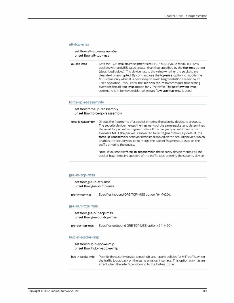
all-tcp-mss
set flow all-tcp-mss numberunset flow all-tcp-mss
Sets the TCP-maximum segment size (TCP-MSS) value for all TCP SYNpackets with an MSS value greater than that specified by the tcp-mss option(described below). The device resets the value whether the packets areclear-text or encrypted. By contrast, use the tcp-mss option to modify theMSS value only when it is necessary to avoid fragmentation caused by anIPsec operation. If you enter the set flow tcp-mss command, that settingoverrides the all-tcp-mss option for VPN traffic. The set flow tcp-msscommand is in turn overridden when set flow vpn-tcp-mss is used.
all-tcp-mss
force-ip-reassembly
set flow force-ip-reassemblyunset flow force-ip-reassembly
Directs the fragments of a packet entering the security device, to a queue.The security device merges the fragments of the same packet and determinesthe need for packet re-fragmentation. If the merged packet exceeds theavailable MTU, the packet is subjected to re-fragmentation. By default, theforce-ip-reassemblybehavior remains disabled on the security device, whichenables the security device to merge the packet fragments, based on thetraffic entering the device.
Note: if you enable force-ip-reassembly, the security device merges all thepacket fragments irrespective of the traffic type entering the security device.
force-ip-reassembly
gre-in-tcp-mss
set flow gre-in-tcp-mssunset flow gre-in-tcp-mss
Specifies inbound GRE TCP-MSS option (64-1420).gre-in-tcp-mss
gre-out-tcp-mss
set flow gre-out-tcp-mssunset flow gre-out-tcp-mss
Specifies outbound GRE TCP MSS option (64-1420).gre-out-tcp-mss
hub-n-spoke-mip
set flow hub-n-spoke-mipunset flow hub-n-spoke-mip
Permits the security device to use hub-and-spoke policies for MIP traffic, whenthe traffic loops back on the same physical interface. This option only has aneffect when the interface is bound to the Untrust zone.
hub-n-spoke-mip
89Copyright © 2012, Juniper Networks, Inc.
Chapter 3: exit Through nsmgmt

initial-timeout
set flow initial-timeout numberunset flow initial-timeout
Defines the length of time in seconds (number, expressed in 10-secondintervals) that the security device keeps an initial session in the session tablebefore dropping it, or until the device receives a FIN or RST packet. The rangeof time is from 20 seconds (setting of 2) to 300 seconds (setting of 30).
initial-timeout
Example:The following command sets the initial timeout value to 1 minute (60 seconds):
set flow initial-timeout 6
icmp-ur-msg-filter
set flow icmp-ur-msg-filterunset flow icmp-ur-msg-filter
Restricts the number of ICMP unreachable message that can flow through asession. Enabling icmp-ur-msg-filter allows only one ICMP unreachablemessage to flow through the session.
NOTE: This command functions only when icmp-ur-session-close behavioris disabled.
icmp-ur-msg-
filter
icmp-ur-session-close
set flow icmp-ur-session-closeunset flow icmp-ur-session-close
Enables a session close upon receipt of an ICMP unreachable message.icmp-ur-session-close
log-dropped-packet
set flow log-dropped-packetunset flow log-dropped-packet
Enables the security device to log details about packets that are either droppedor denied access by the security device. By default, this feature is disabled.
You can view the logs of the dropped packets by using the get log flow-denycommand. You can clear the logs of the dropped traffic by using the clear logflow-deny command.
NOTE: You should enable this command only for debug purpose. This isbecause a large volume of traffic might hit the device in general and getdropped. If the log-dropped-packet feature is enabled in such a case, the tasklog records all dropped packets, which leads to high CPU utilization. You candisable this feature by using the unset flow log-dropped-packet command.
log-dropped-packet
mac-flooding
set flowmac-flooding
Copyright © 2012, Juniper Networks, Inc.90
IPv6 Command Descriptions

unset flowmac-flooding
Enables the security device to pass a packet across the firewall even if itsdestination MAC address is not in the MAC learning table.
mac-flooding
max-frag-pkt-size
set flowmax-frag-pkt-size numberunset flowmax-frag-pkt-size
The maximum allowable size for a packet fragment generated by thesecurity device. You can set the number value between 1024 and 1500inclusive.
For example, if a received packet is 1540 bytes andmax-frag-pkt-sizeis 1460 bytes, the device generates two fragment packets. The first is1460 bytes and the second is 80 bytes. If you resetmax-frag-pkt-sizeto 1024, the first fragment packet is 1024 bytes and the second is 516bytes.
max-frag-pkt-size
Example: The following command sets the maximum size of a packet generated by the
security device to 1024 bytes:
set flowmax-frag-pkt-size 1024
multicast idp
set flowmulticast idpunset flowmulticast idp
Enables the security device to inspect multicast IPv6 traffic.
NOTE: For multicast traffic inspection, all the outgoing interfaces shouldbelong to the same zone.
multicast
no-tcp-seq-check
set flow no-tcp-seq-checkunset flow no-tcp-seq-check
Skips the sequence number check in stateful inspection.no-tcp-seq-check
path-mtu
set flow path-mtuunset flow path-mtu
Enables path-MTU (maximum transmission unit) discovery. If the securitydevice receives a packet that must be fragmented, it sends an ICMP packetsuggesting a smaller packet size.
path-mtu
91Copyright © 2012, Juniper Networks, Inc.
Chapter 3: exit Through nsmgmt

perf
get flow perf
Displays the performance information.perf
route-change-timeout
set flow route-change-timeout numberunset flow route-change-timeout number
Sets and unsets the the session timeout value on a route change to anonexistent route. You can set number between 6 and 1800 secondsinclusive. Unsetting this keyword removes the route-change-timeoutvalue, causing sessions to time out based on their original timeout, if aroute change occurs and no new route is found.
If route-change is not set, the current behavior is maintained, andsessions discovered to have no route are aged out using their currentsession timeout values.
route-change-timeout
syn-proxy syn-cookie
set flow syn-proxy syn-cookieunset flow syn-proxy syn-cookie
Sets the flow from the traditional SYN Proxy mode to SYN Cookie mode.SYN Cookie is enabled globally on the security device and is activatedwhen the configured syn-flood attack-threshold is exceeded.
syn-proxy syn-cookie
tcp-mss
tcp-rst-invalid-session get flow tcpmssset flow tcpmss [ number ]unset flow tcpmss
Sets the TCP-maximum segment size (TCP-MSS) value for all TCP SYNpackets for outbound VPN traffic only. The security device modifies the MSSvalue in the TCP packet to avoid fragmentation caused by the IPsec operation.The value set using set flow vpn-tcp-mss command takes precedence overthe one set by set flow tcp-mss.
tcp-mss
tcp-rst-invalid-session
set flow tcp-rst-invalid-sessionunset flow tcp-rst-invalid-session
Directs the device to immediately terminate and reset a sessionwhen TCP packets have enabled reset bits.
tcp-rst-invalid-session
tcp-syn-bit-check
set flow tcp-syn-bit-check
Copyright © 2012, Juniper Networks, Inc.92
IPv6 Command Descriptions

unset flow tcp-syn--bit-check
Checks the TCP SYN bit before forwarding the packet to the processor forsession creation. SYN bit check is done in the application-specific integratedcircuit (ASIC), and the packet is forwarded to the processor for sessioncreation. This improves throughput performance. If the SYN bit is not set inthe first packet received, the security device drops the packet. This is thedefault.
The tcp-syn-bit-check feature is a subset of tcp-syn-check; if you want toenable just tcp-syn-bit-check, you must disable tcp-syn-check, which isdisabled by default.
tcp-syn-bit-check
The Resulting Behavior column in the following table shows the effect or effects of various
combinations of TCP SYN bit-screening configuration.
1. Check the TCP SYN bit before creating a session in the processor.
2. Check the TCP SYN bit before creating a session is in the ASIC.
3. Refresh the session after the three-way handshake.
4. Check the TCP SYN bit on traffic from the tunnel
TCP SYN configuration is the same on all security devices, whether ASIC-based or not.
Resulting Behaviortcp-syn-check-in-tunneltcp-syn-bit-checktcp-syn-check
2,3,4enablen/aenable
1,3disabledn/aenabled
2,4enabledenableddisabled
1disabledenableddisabled
noneenableddisableddisabled
nonedisableddisableddisabled
tcp-syn-check
set flow tcp-syn-checkunset flow tcp-syn-check
Checks the TCP SYN bit before creating a session , and refreshes the sessionafter the TCP three-way handshake. If the SYN bit is not set, the securitydevice drops the packet.
The tcp-syn-check feature is a superset of tcp-syn-bit-check; thereforeenabling tcp-syn-check enables tcp-syn-bit-check as well. If you want toenable just tcp-syn-bit-check, you must disable tcp-syn-check.
tcp-syn-check
93Copyright © 2012, Juniper Networks, Inc.
Chapter 3: exit Through nsmgmt

tcp-syn-check-in-tunnel
set flow tcp-syn-check-in-tunnelunset flow tcp-syn-check-in-tunnel
Checks the TCP SYN bit before creating a session for tunneledpackets. By default, the security device checks that the SYN bit isset in the first packet of a VPN session. If it is not set, the securitydevice drops it.
tcp-syn-check-in-tunnel
vpn-tcp-mss
set flow vpn-tcp-mss [ number ]unset flow vpn-tcp-mss
Sets the TCP-maximum segment size (TCP-MSS) value for all TCP SYNpackets for both outbound and inbound VPN traffic.
Note: For VPN traffic, the tcp-mss or vpn-tcp-mss command can be used.If both commands are set, the latter command has precedence over theformer. If both commands are not set, all-tcp-mss command is used. Youneed to unset thevpn-tcp-msscommand to make the device use the tcp-msscommand. When thevpn-tcp-msscommand is used, an MSS value configuredby the tcp-mss command will not be valid even if the tcp-mss command isrun again.
vpn-tcp-mss
Defaults
The default initial timeout value is 2 (20 seconds).
The MAC-flooding feature is enabled by default.
gate
Use the gate command to check the number of gates on the security device, how many
are in use, and how many are still available.
Gates are logical access points in the firewall for FTP and similar applications. The security
device creates the gates, then converts a gate for each new session when data traffic
occurs.
Syntax
get gate
Keywords and Variables
None.
Defaults
The number of default gates varies by device. For more information, see the datasheet
for your security device.
Copyright © 2012, Juniper Networks, Inc.94
IPv6 Command Descriptions

group
Use the group commands to group several addresses or several services under a single
name.
A group allows you to reference a group of addresses or services by a single name in a
policy. This eliminates the need for a separate policy for each address or service. For
example, you can create a service group that includes FTP, HTTP, and HTTPS services,
and then reference that group in a policy.
NOTE: Although a single policy might reference a service group with threemembers, the security device generatesmultiple internal rules from thatpolicy. Overusing address and service groups with highmember counts canunexpectedly consume internal resources.
Syntax
get
get group { address zone [ grp_name ] | service [ grp_name ] }
set
set group{address zone grp_name [ ipv6 ] [ add name_str ] [ comment string ] |service grp_name [ add name_str ] [ comment string ]}
Keywords and Variables
add
set group address zone grp_name [ ipv6 ] [ addmbr_name ] [ comment string ]set group service grp_name [ addmbr_name [ comment string ] ]
Adds an address or a service namedmbr_name.add name_str
Examples: The following command creates an address group named engineering for
the Trust zone and adds the address hw-eng to the group:
set group address trust engineering add hw-eng
The following command creates a service group named inside-salesand adds the service
AOL to the group:
set group service inside-sales add AOL
address
get group address zone [ ... ]set group address zone grp_name [ ... ]
95Copyright © 2012, Juniper Networks, Inc.
Chapter 3: exit Through nsmgmt

unset group address zone grp_name [ ... ]
Performs the operation on an address group. The zone value specifies thezone to which the address group is bound. This zone is either a default securityzone or a user-defined zone. For more information, see “Interfaces” on page 355.
address
Example: The following command creates an empty address group (named
headquarters) for the Trust zone:
set group address trust headquarters
clear
unset group address zone grp_name clearunset group service grp_name clear
Removes all the members of an address or service group.clear
Example: The following command removes all members from an address group
(engineering) bound to the Trust zone:
unset group address trust engineering clear
comment
set group address zone grp_name [ ... ] [ comment string ]set group service grp_name [ ... ] [ comment string ]
Adds a comment string to the service group or address group entry.comment
Example: The following command creates an address group named engineering for the
Trust zone, adds the address hw-eng to the group, and includes a comment about the
group:
set group address trust engineering add hw-eng comment “Engineering Group”
remove
unset group address zone grp_name remove name_strunset group service grp_name remove name_str
Removes the address (or service) named name_str. If you do not specify anaddress (or service) group member, the unset group { address | service }command deletes the entire address group or service group.
remove
Example:The following command removes the addressadmin-pc from theengineeringaddress group:
unset group address trust engineering remove admin-pc
service
get group service grp_nameset group service grp_name [ ... ]
Copyright © 2012, Juniper Networks, Inc.96
IPv6 Command Descriptions

unset group service grp_name [ ... ]
Performs the operation on a service group.service grp_name
Example: The following command creates an empty service group and names it
web_browsing:
set group service web_browsing
Notes
Each address group and service group you create must have a unique name. You cannot
use the same address group name as a service group name.
You cannot add the predefined address or service named any to a group.
While a policy references a group, you cannot remove the group, although you can modify
it.
From the console, you can add only one member to a group at a time.
group-expression
Use the group-expression commands to set up or display group expressions for use in
security policies.
A group expression allows you to include or exclude users or user groups, according to
NOT, AND, or OR operators. Such expressions are only usable for external users and user
groups.
Syntax
get
get group-expression{name_str |all |id number}
set
set group-expression name_str{not name_str |name_str { and | or } name_str |id number |}
Keywords and Variables
Variables
get group-expression name_str
97Copyright © 2012, Juniper Networks, Inc.
Chapter 3: exit Through nsmgmt

set group-expression name_strunset group-expression name_str
The name of the group expression.name_str
all
get group-expression all
Specifies all group expressions.all
and | or
set group-expression name_str name_str and name_strset group-expression name_str name_str or name_str
Specifies AND or OR relationship between users, user groups, or groupexpressions.
and | or
Example: The following commands create group expressions SalesM and SM_Group,
place them in an OR relationship, and then place SM_Group andOffice_1 in an AND
relationship:
set user-group Sales_Group location externalset user-groupMarketing_Group location externalset group-expression SalesM Sales_Group or Marketing_Groupset group-expression SM_Group Office_1 and SalesM
id
get group-expression id numberset group-expression name_str id numberunset group-expression id number
Specifies an identification number for the group expression.id number
not
set group-expression name_str not name_str
Specifies negation.not
Example: The following command creates a NOT group expression that does not allow
theOffice_1 user:
set group-expression Total_Users not Office_1
hostname
Use the hostname commands to define the security device name. This name always
appears in the console command prompt.
Copyright © 2012, Juniper Networks, Inc.98
IPv6 Command Descriptions

The hostname is a character string that identifies the security device. If you define a
hostname for the device (such as ns500gate) and a domain name for the device (such
as “netscreen,” using the domain command), you can use the hostname and domain
name (ns500gate.netscreen) as a gateway for a VPN tunnel.
Syntax
get
get hostname
set
set hostname string
Keywords and Variables
Variables
Sets the name of the security device.string
Example: The following command changes the security device hostname to acme:
set hostname acme
ike
Use the ike commands to define the Phase 1 and Phase 2 proposals and the gateway for
an AutoKey Internet Key Exchange (IKE) VPN tunnel and to specify other IKE parameters.
To establish an AutoKey IKE IPsec tunnel between peer devices, two phases of negotiation
are required:
• In Phase 1, the peer devices establish a secure channel in which to negotiate the IPsec
SAs.
• In Phase 2, the peer devices negotiate the IPsec SAs for encrypting and authenticating
the ensuing exchanges of user data.
The gateway definition identifies the devices or remote users with which the security
device establishes the VPN tunnel.
Syntax
exec
exec ike preshare-gen name_str usr_str
get
get ike{accept-all-proposal |ca-and-type |cert |
99Copyright © 2012, Juniper Networks, Inc.
Chapter 3: exit Through nsmgmt

conn-entry |cookies |gateway [ name_str ] |heartbeat |id-mode |initial-contact [ all-peers | single-gateway [ name_str ] ] |initiator-set-commit |member-sa-hold-time |p1-max-dialgrp-sessions |p1-proposal name_str |p1-sec-level |p2-proposal name_str |p2-sec-level |policy-checking |respond-bad-spi |responder-set-commit |soft-lifetime-buffer}
set
Phase 1 Proposal
set ike p1-proposal name_str[ dsa-sig | rsa-sig | preshare ][ group1 | group2 | group5 ]{ esp{ 3des | des | aes128 | aes192 | aes256{md5 | sha-1[days number |hours number |minutes number |seconds number]
}}
}
Phase 2 Proposal
set ike p2-proposal name_str[ group1 | group2 | group5 | no-pfs ]{esp [ 3des | des | aes128 | aes196 | aes256 | null ] |ah}[ md5 | null | sha-1[days number |hours number |minutes number |seconds number ]][ kbyte number ]
]}
Copyright © 2012, Juniper Networks, Inc.100
IPv6 Command Descriptions

Gateway Tunnel
set ike gateway name_str{address { ip_addr | hostname[.dom_name ] [ id ] }dialup { usr_str | grp_name } |dpd-liveness{always-send |interval number1 |retry number2} |
dynamic{string |asn1-dn { [ container string ] [ wildcard string ] |fqdn string |ip-addr string |u-fqdn string} |
}[ aggressive | main ] [ local-id id_str ][ outgoing-interface interface[ outgoing-zone zone ]
][ preshare key_str | seed-preshare key_str ]{sec-level { basic | compatible | standard } |proposal name_str1[ name_str2 ] [ name_str3 ] [ name_str4 ]
} |modecfg
{client{action update-dhcpserver |admin-preference number |pd interface interface [ sla-id id_num [ sla-len number ] ] |
server { action add-route | info-origin local dns }
IKE Heartbeat
set ike gateway name_str heartbeat{hello number |threshold number |reconnect number}
Certificates
set ike gateway name_str cert{my-cert id_num |peer-ca [ id_num | all ] |peer-cert-type { pkcs7 | x509-sig }}
101Copyright © 2012, Juniper Networks, Inc.
Chapter 3: exit Through nsmgmt

NAT-Traversal
set ike gateway name_str nat-traversal[udp-checksum |keepalive-frequency number]
XAuth
set ike gateway name_str xauth[client { any | chap | securid } username name_str password name_str |server name_str[ chap ] [ query-config ] [ user name_str | user-group name_str ] |
bypass-auth]
Other IKE Command Switches
set ike{accept-all-proposal |id-mode { ip | subnet } |initial-contact[all-peers |single-gateway name_str] |
initiator-set-commit |member-sa-hold-time number |p1-max-dialgrp-sessions { count number | percentage number } |policy-checking |respond-bad-spi spi_num |responder-set-commit | responder-mode |single-ike-tunnel name_str |soft-lifetime-buffer number}
Keywords and Variables
accept-all-proposal
get ike accept-all-proposalset ike accept-all-proposalunset ike accept-all-proposal
Directs the security device to accept all incoming proposals. By default,the device accepts only those proposals matching predefined oruser-defined proposals. This command is primarily useful whentroubleshooting AutoKey IKE tunnels.
accept-all-proposal
Copyright © 2012, Juniper Networks, Inc.102
IPv6 Command Descriptions

address
set ike gateway address { ip_addr | name_str } { ... }
Defines the remote IKE gateway address as an IP address, as a hostname, oras a fully qualified domain name (FQDN, which is a hostname + domainname). Use this option to set up a site-to-site VPN.
NOTE: If you specify a hostname or an FQDN that the security device cannotresolve to an IP address, the IKE gateway is classified as disabled.
address
Example:The following command specifieswww.juniper.netas the address of a remote
IKE gateway named jn1, defines the preshared key as 7a850wq, and specifies the Phase
1 security level as compatible:
set ike gateway jn1 address www.juniper.net preshare 7a850wq sec-level compatible
NOTE: The compatible security level for Phase 1 negotiations includes thefollowingfourproposals:pre-g2-3des-sha,pre-g2-3des-md5,pre-g2-des-sha,and pre-g2-des-md5.
aggressive | main
set ike gateway name_str { ... } aggressive [ ... ]set ike gateway name_str { ... } main [ ... ]
Defines the mode used for Phase 1 negotiations. Use aggressive mode onlywhen you need to initiate an IKE key exchange without ID protection, as whena peer unit has a dynamically assigned IP address. Main mode is therecommended key-exchange method because it conceals the identities ofthe parties during the key exchange.
aggressive |main
ca-and-type
get ike ca-and-type
Displays the supported certificate authorities (CAs) and certificate types.ca-and-type
cert
get ike certset ike gateway name_str cert my-cert id_numset ike gateway name_str cert peer-ca [ id_num | all ]set ike gateway name_str cert peer-cert-type { pkcs7 | 509-sig
Uses a digital certificate to authenticate the VPN initiator and recipient.cert
103Copyright © 2012, Juniper Networks, Inc.
Chapter 3: exit Through nsmgmt

Specifies which certificates to use.
• my-certname_str—Specifies a particular certificate when the local securitydevice has multiple loaded certificates.
• peer-ca name_str—Specifies a preferred certificate authority (CA).
• peer-cert-type { pkcs7 | x509 }—Specifies a preferred type of certificate(PKCS7 or X509).
If you set the peer-ca and peer-cert-type values, the device inserts themin any certificate request it sends to the peer. If the peer has multiple localcertificates, these values help the peer select a certificate.
NOTE: The security device does not use the peer-ca or peer-cert-typesettings to check certificates received from the peer.
If possible, the peer should send a certificate issued by the peer-ca CA.However, if the peer sends a certificate issued by a different CA, the securitydevice searches local memory for the certificate of the issuing CA; if the searchis successful, the device accepts the peer certificate. If the search isunsuccessful, the device uses a certificate issued by a different CA.
gatewayname_str cert
conn-entry
get ike conn-entry
Displays the Connection Entry Table.conn-entry
cookies
get ike cookies
Displays the cookie table, and the total number of dead and active cookies.cookies
dialup
set ike gateway name_str dialup { usr_str | grp_name } [ ... ]
Identifies an IKE dialup user (usr_str) or dialup group (grp_name). Use thisoption to set up a dialup VPN. To specify a user’s attributes, use the set usercommand. (To specify dialup group attributes, use the set user-groupcommand.)
dialup
dpd-liveness
get ike gateway name_str dpd-livenessset ike gateway name_str dpd-liveness { always-send | interval number1 | reconnectinterval | retry number2 }
Copyright © 2012, Juniper Networks, Inc.104
IPv6 Command Descriptions

unset ike gateway name-str dpd-liveness [ ... ]
Configures the device to use dead-peer detection (DPD), a protocol used bysecurity devices to verify the current existence and availability of IPsec peerdevices. A device performs this verification by sending encrypted IKE Phase1 notification payloads (R-U-THERE) to peers, and waiting for DPDacknowledgements (R-U-THERE-ACK).
• always-send—Instructs the device to send DPD requests regardless ofwhether there is outgoing IPsec traffic to the peer.
• interval number1—Specifies the DPD interval. This interval is the amountof time (expressed in seconds) the device allows to pass before consideringa peer to be dead. The device considers the peer dead when all of thefollowing conditions apply after the DPD interval expires:
• The device received no matching R-U-THERE-ACK response after sendingthe configured number of transmitted R-U-THERE requests to the peer.
• There was no incoming IPsec traffic from the peer on any of the IPsecSAs.
• The device received no R-U-THERE request from DPD peer.
• reconnect interval—Sets the interval (in seconds) after which the securitydevice renegotiates the failed tunnel with the peer considered to be dead.The allowable range is from 60 to 9999 seconds.
• retry number2—The maximum number of times to send the R-U-THERErequest before considering the peer to be dead.
dpd-liveness
dynamic
set ike gateway name_str dynamic { ... } [ ... ]
Specifies the identifier for the remote gateway with a dynamic IP address.Use this option to set up a VPN with a gateway that has an unspecified IPaddress.
• string—A string you can use as a peer ID.
• asn1-dn [ container ] [ wildcard ] string—The ASN1 domain name. Thecontainer switch treats string as a container. Thewildcard switch treatsstring as a wild card.
• fqdn—The fully qualified domain name (such as www.acme.com).
• ip_addr string—The IP address of the remote gateway interface.
• u-fqdn string—The user fully qualified domain name (such [email protected]).
dynamic
gateway
get ike gatewayset ike gateway name_str { ... } [ ... ]unset ike gateway { ... }
Configures or displays settings for a remote tunnel gateway.gateway
heartbeat
get ike heartbeatset ike gateway name_str heartbeat { ... }
105Copyright © 2012, Juniper Networks, Inc.
Chapter 3: exit Through nsmgmt

unset ike gateway heartbeat { ... }
Specifies the IKE heartbeat protocol parameters.
• hello number—Sets the IKE heartbeat protocol interval (in seconds).
• reconnectnumber—Sets the quiet interval (in seconds) that elapses beforethe security device reconnects a failed tunnel.
• threshold number—Sets the number of retries before the security deviceconsiders the connection lost and removes all Phase 1 and Phase 2 keysrelated to this gateway.
heartbeat
id-mode
get ike id-modeset ike id-mode ipset ike id-mode subnet
Defines the IKE ID mode in the Phase 2 exchange as either a host (IP) addressor a gateway (subnet). If you use the ip switch, the device sends no Phase 2ID. If you choose the subnet switch, the device sends proxy Phase 2 IDs. (Usethe ip switch when setting up a VPN tunnel between a security device and aCheckPoint 4.0 device. Otherwise, use the subnet switch.)
id-mode
initial-contact
get ike initial-contactset ike initial-contact [ all-peers | single-gateway name_str ]unset ike initial-contact
Determines how the security device performs initial contact with an IKE peer.
• Specifying all-peers—Instructs the security device to delete all SAs, thensend an initial contact notification to each IKE peer.
• Specifyingsingle-gateway name_str—Instructs the security device to deleteall SAs associated with the specified IKE gateway, then send an initialcontact notification.
If you specify none of the above options, the security device sends an initialcontact notification to all peers during the first IKE single-user session aftera system reset.
initial-contact
initiator-set-commit
get ike initiator-set-commitset ike initiator-set-commitunset ike initiator-set-commit
When the security device performs as an IKE initiator, sets the commitbit in the ISAKMP header. The party who sends the last message in theexchange does not use the new IPsec SA until it receives confirmationfrom the other party.
initiator-set-commit
Copyright © 2012, Juniper Networks, Inc.106
IPv6 Command Descriptions

local-id
set ike gateway name_str { ... } local-id id_str [ ... ] { ... }
Defines the IKE ScreenOS identity of the local device. The device sends thisID to the remote gateway during IKE negotiation.
To instruct the security device to derive the IKE identity from the DistinguishedName (DN) in the local certificate, specify the following for local-id (includingsquare brackets):
[DistinguishedName]
If there is more than one certificate on your security device, you may need tospecify which certificate to use. For more information, see “cert” on page 103.
local-id
member-sa-hold-time
get ikemember-sa-hold-timeset ikemember-sa-hold-time numberunset ikemember-hold-sa
The length of time (in minutes) the device keeps an unused SAallocated for a dialup user.
member-sa-hold-time
modecfg client
set ike gateway name_strmodecfg client action update-dhcpserverset ike gateway name_strmodecfg client admin-preference numberset ike gateway name_strmodecfg client pd interface interface[ sla-id id_num [ sla-len number ] ]
107Copyright © 2012, Juniper Networks, Inc.
Chapter 3: exit Through nsmgmt

unset ike gateway name-str modecfg
ModeCFG allows ISPs to delegate IPv6 prefixes or addresses to the XAuthclient.
• action update-dhcpserver—Instructs the security device to distribute thereceived XAuth configuration information (DNS and WINS) to DHCP serverson other interfaces and to the device itself.
• admin-preference number—Sets the local preference (number) forconfiguration information learned through sources that use XAuth, PPPoE,DHCPv6, DHCP, or another protocol. The preference number determineswhich source to use first.
The device can learn the DNS server addresses statically (from the WebUIor the CLI), or it can learn them dynamically from PPPoE, DHCP or XAuth.The device stores these learned addresses in the DNS server list. It thenselects the best two addresses from this list and designates them as theprimary and secondary DNS server addresses. The admin-preferencenumbersetting specifies how much preference the device gives to addresseslearned through one source or protocol, in comparison with another sourceor protocol. To do this, it uses an election protocol.
First, the device compares theadmin-preference values. If the values differ,it selects the address with the highest value. If the values are identical, ituses the highest protocol. (The protocol levels, from highest to lowest, arePPPoE, XAuth, DHCP, and CLI, respectively.) If the protocols are identical,it chooses the address with the greatest numerical value.
• pd—Enables the client to receive delegated prefixes and use them toconfigure networks or subnets on separate interfaces.
• sla-id id_num1—Identifies the Site-Local Aggregate (SLA) number, aninteger value that denotes a subnet of the network connected to theinterface. This value can be up to 16 bits in length.
• sla-len id_num2—Specifies the length of the SLA (expressed in bytes).This value can range from 0 to 16.If you specify a sla-id id_num1 and sla-len id_num2 of zero, the deviceautomatically right-aligns the SLA to 64 bits by padding it with zeroes.For example, if the XAuth server delegates the prefix 15::/48, and theSLA is 0, the resulting prefix is 15:0:0:0::/64 (or 15::/64). If the SLA is 3,the resulting prefix is 15:0:0:3::/64.
modecfg client
modecfg server
set ike gateway name_str modecfg server { action add-route | info-origin local dns }unset ike gateway name_str modecfg server action add-route{ action add-route | info-origin local dns }
Allows the XAuth/Modecfg server to add a route for each IPv4 address andnetmask or for each IPv6 address and prefix length assigned to the client froman upstream router.
modecfg server
nat-traversal
set ike gateway name_str nat-traversal udp-checksumset ike gateway name_str nat-traversal keepalive-frequency number
Copyright © 2012, Juniper Networks, Inc.108
IPv6 Command Descriptions

unset ike gateway name_str nat-traversal [ ... ]
Enables or disables IPsec NAT Traversal, a feature that allows transmissionof encrypted traffic through a security device configured for NAT. The NATTraversal feature encapsulates ESP packets into UDP packets. This preventsthe NAT device from altering ESP packet headers in transit, thus preventingauthentication failure on the peer security device.
• udp-checksum—Enables the NAT-Traversal UDP checksum operation(used for UDP packet authentication).
• keepalive-frequency—Specifies the frequency (in seconds) with which thesecurity device sends NAT-traversal keepalive messages.
nat-traversal
Examples: The following command enables NAT traversal for a gateway namedmktg:
set ike gatewaymktg nat-traversal
The following command sets the Keepalive setting to 25 seconds:
set ike gatewaymktg nat-traversal keepalive-frequency 25
outgoing-interface
set ike gateway name_str { ... } outgoing-interface interface [ ... ]
Defines the interface through which the security device sends IKE trafficfor this gateway.
outgoing-interface
Example: The following commands, executed on a local security device, configure the
device to request service from a HTTP server in Paris. The security device exchanges all
HTTP packets through a VPN tunnel.
• Remote gateway: Paris_Gateway
• Remote gateway interface IPv6 address: 3a55::130:6:aff:fe3a
• Outgoing interface: ethernet3
• Local IPv6 address for ethernet3: 21e4::e443:a1ff:feb6
• VPN tunnel (Paris_Tunnel) uses the defined gateway Paris_Gateway
set interface ethernet3 zone untrustset interface ethernet3 ipv6mode hostset interface ethernet3 ipv6 enableset interface ethernet3 ipv6 ip 21e4::e443:a1ff:feb6/64set ike gateway Paris_Gateway address 3a55::130:6:aff:fe3a outgoing-interfaceethernet3 local-address 21e4::e443:a1ff:feb6 proposal dsa-g2-aes128-md5set vpn Paris_Tunnel gateway Paris_Gateway proposal g2-esp-aes128-shaset address trust Our_Local 21e4::e443:a1ff:feb6/64set address untrust Their_Remote 3a55::130:6:aff:fe3a/64set policy from trust to untrust Our_Local Their_Remote http tunnel vpnParis_Tunnel
p1-max-dialgrp-sessions
get ike p1-max-dialgrp-sessionsset ike p1-max-dialgrp-sessions count number
109Copyright © 2012, Juniper Networks, Inc.
Chapter 3: exit Through nsmgmt

set ike p1-max-dialgrp-sessions percentage numberunset ike p1-max-dialgrp-sessions
Displays the allowed concurrent Phase 1 negotiations for dialupgroups.
p1-max-dialgrp-sessions
p1-proposal
get ike p1-proposal name_strset ike p1-proposal name_str [ ... ] { ... }unset ike p1-proposal name_str
Names the IKE Phase 1 proposal, which contains parameters for creating andexchanging session keys and establishing Phase 1 security associations.
• dsa-sig | rsa-sig | preshare—Specifies the method to authenticate thesource of IKE messages. preshare refers to a preshared key, which is a keyfor encryption and decryption that both participants have before beginningtunnel negotiations. rsa-sig and dsa-sig refer to two kinds of digitalsignatures, which are certificates that confirm the identity of the certificateholder. (The default method is preshare.)
• group1 | group2 | group5—Identifies the Diffie-Hellman group, a techniquethat allows two parties to negotiate encryption keys over an insecuremedium; such as, the Internet. Group2 is the default group.
• esp—Specifies Encapsulating Security Payload protocol, which providesencryption and authentication.
• des | 3des | aes128 | aes192 | aes256—Specifies the encryption algorithm.
• md5|sha-1—Specifies the authentication (hashing) algorithm used in ESPprotocol. The default algorithm is SHA-1, the stronger of the two algorithms.
• The following parameters define the elapsed time between each attemptto renegotiate a Phase 1 security association. The minimum allowablelifetime is 180 seconds. The default lifetime is 28800 seconds.
• days number
• hours number
• minutes number
• seconds number
p1-proposal
Example: The following command defines a Phase 1 proposal named sf1.
• Preshared key and a group 1 Diffie-Hellman exchange
• Encapsulating Security Payload (ESP) protocol using the 3DES and MD5 algorithms
• Lifetime of 3 minutes
set ike p1-proposal sf1 preshare group1 esp 3desmd5minutes 3
p1-sec-level
get ike p1-sec-level
Displays the predefined IKE Phase 1 proposals in descending order of securitylevel.
p1-sec-level
Copyright © 2012, Juniper Networks, Inc.110
IPv6 Command Descriptions

p2-sec-level
get ike p2-sec-level
Displays the predefined IKE Phase 2 proposals in descending order of securitylevel.
p2-sec-level
p2-proposal
get ike p2-proposal name_strset ike p2-proposal name_str [ ... ] { ... }set ike p2-proposal name_str
Names the IKE Phase 2 proposal. This proposal defines parameters for creatingand exchanging a session key to establish a security association (SA).
• group1 | group2 | group5 | no-pfs—Defines how the security devicegenerates the encryption key. Perfect Forward Secrecy (PFS) is a methodfor generating each new encryption key independently from the previouskey. Selecting no-pfs turns this feature off, so IKE generates the Phase 2key from the key generated in the Phase 1 exchange. If you specify one ofthe Diffie-Hellman groups, IKE automatically uses PFS when generatingthe encryption key. The default is Group 2.
• ah | esp In a Phase 2 proposal, identifies the IPsec protocol.
• esp [ des | 3des | aes128 | aes192 | aes256 ]—Specifies EncapsulatingSecurity Payload (ESP) protocol, which provides both encryption andauthentication. Specifies the encryption algorithm used in ESP protocol.(The default protocol is des.)
• ah—Specifies Authentication Header (AH) protocol, which providesauthentication only.
• md5 | null | sha-1—Specifies the authentication (hashing) algorithm usedin ESP or AH protocol. The default algorithm is MD5 for non-FIPS mode,and SHA is the default for FIPS mode. The null switch specifies noauthentication.
• The following parameters define the elapsed time between each attemptto renegotiate a security association. The minimum allowable lifetime is180 seconds. The default lifetime is 28800 seconds.
• days number
• hours number
• minutes number
• seconds number
• kbytes number—Indicates the maximum allowable data flow in kilobytesbefore ScreenOS renegotiates another security association. The defaultvalue is0 (infinity).
p2-proposal
Example: The following command specifies Phase 2 proposal g2-esp-3des-null.
• Group 2 Diffie-Hellman exchange
• ESP using 3DES without authentication
• Lifetime of 15 minutes
set ike p2-proposal g2-esp-3des-null group2 esp 3des null minutes 15
111Copyright © 2012, Juniper Networks, Inc.
Chapter 3: exit Through nsmgmt

policy-checking
get ike policy-checkingset ike policy-checkingunset ike policy-checking
Checks to see if the policies of the two peers match before establishing aconnection. Use policy checking when configuration on the peer gatewayssupport multiple tunnels. Otherwise, the IKE session fails. You can disablepolicy checking when only one policy is configured between two peers.
policy-checking
preshare
set ike p1-proposal name_str preshare [ ... ]
Directs the device to use preshared key authentication for IKE Phase 1negotiation. In this mode, both peer devices use a shared password to generatea encryption and decryption key.
preshare
set ike gateway name_str { ... } [ ... ] preshare key_str
Specifies the Preshared key (key_str) used in the Phase 1 proposal. (If you usean RSA- or DSA-signature in the Phase 1 proposal, do not use this option).
preshare
Example: For an example of this option, see “Setting Up a Policy-Based VPN Tunnel” on
page 117.
preshare-gen
exec ike preshare-gen name_str usr_str
Generates an individual preshared key for a remote dialup user associatedwith a Group IKE ID user. The security device generates each preshared keyfrom a seed value (specified in the command set ike gateway). After thedevice generates the preshared key, you can use it to set up a configurationfor the remote user. (Remove any spaces.)
• name_str—IKE gateway name. To create such a gateway, use the set ikegateway name_str command.
• usr_str—Full IKE ID of an individual user, which belongs to a Group IKE IDuser. To create such a user, use the set user name_str ike-id command. TheGroup IKE ID user must be associated with a dialup user group to supporta group of users.
preshare-gen
Example:The following commands create a single group IKE ID user and assign the user
to a dialup user group. Then they create VPNs and policies that allow dialup users with
matching partial IKE ID values to establish secure communication through the security
device.
• The name of the group IKE ID user is User1, with partial IKE identity of acme.com.
• The number of dialup users that can share this user’s IKE identity is 10.
• The dialup user group is Office_1.
Copyright © 2012, Juniper Networks, Inc.112
IPv6 Command Descriptions

• The seed value for creating the preshared key is jk930k.
• The Phase 1 IKE gateway defined for the server side is Corp_GW.
• The Phase 2 VPN defined for the server side is Corp_VPN.
• The Phase 1 IKE gateway defined for the client side is Office_GW.
• The Phase 2 VPN defined for the client side is Office_VPN.
• The individual user’s full IKE identity is [email protected].
• The trusted server that dialup users access from the outside is a Web server with IP
address 1.1.110.200.
set user User1 ike-id u-fqdn acme.com share-limit 10set user-group Office_1 user User1set ike gateway Corp_GWdialup Office_1 aggressive seed-preshare jk930kproposal pre-g2-3des-md5
set vpn Corp_VPN gateway Corp_GW tunnel proposal g2-esp-3des-md5set address trust http_server 1.1.110.200 255.255.255.255set policy incoming “dial-up vpn” http_server any tunnel vpn Corp_VPN
To generate the preshared key for [email protected]:
exec ike preshare-gen Corp_GW [email protected]
NOTE: For this example, assume that this command generatesc5d7f7c1806567bc57d3d30d7bf9b93baa2adcc6.
On the client side:
set ike gateway Office_GW address 10.1.10.10 aggressive local-id [email protected] c5d7f7c1806567bc57d3d30d7bf9b93baa2adcc6 proposalpre-g2-3des-md5
set vpn Office_VPN gateway Office_GW tunnel proposal g2-esp-3des-md5set address untrust http_server 1.1.110.200set policy outgoing “inside any” http_server any tunnel vpn Office_VPN
proposal
set ike gateway name_str { ... } [ ... ] proposal name_str1[ name_str2 ] [ name_str3 ] [ name_str4 ]
Specifies the name (name_str) of a proposal. You can specify up to four Phase1 proposals.
proposal
Example: For an example of this option, see “Setting Up a Policy-Based VPN Tunnel” on
page 117.
respond-bad-spi
get ike respond-bad-spiset ike respond-bad-spi [ number ]
113Copyright © 2012, Juniper Networks, Inc.
Chapter 3: exit Through nsmgmt

unset ike respond-bad-spi
Responds to packets with bad security parameter index (SPI) values. Thespecified number value is the number of times to respond to bad SPIs pergateway.
respond-bad-spi
responder-set-commit
get ike responder-set-commitset ike responder-set-commitunset ike responder-set-commit
Directs the security device to set the commit bit in the ISAKMPheader when the device acts as an IKE responder. The peer thatsends the last message in the exchange does not use the new IPsecSA until it receives information from the other peer.
responder-set-commit
responder-mode
set ike responder-modeunset ike responder-mode
Enables the security device to act as a responder but not as aninitiator, when performing IKE negotiation.
responder-mode
sec-level
set ike gateway name_str { ... } [ ... ] sec-level { ... }
Specifies which predefined security proposal to use for IKE. Thebasicproposalprovides basic-level security settings. The compatible proposal provides themost widely used settings. The standard proposal provides settingsrecommended by Juniper Networks.
sec-level
Example:The following command specifies the predefined security proposalcompatible:
set vpn Corp_VPN gateway Corp_GW sec-level compatible
seed-preshare
set ike gateway name_str { ... } [ ... ] seed-preshare key_str
Specifies a seed value (key_str) for a user group with Preshared Keyconfigurations. Such a configuration performs IKE authentication for multipledialup users, each with an individual preshared key, without having a separateconfiguration for each user. Instead, use the seed to generate the presharedkey with the exec ike preshare-gen command.
seed-preshare
Example: The following commands configure IKE authentication for multiple dialup
users in a user group:
• Interface ethernet1 bound to the Trust zone and interface ethernet3 bound to the
Untrust zone
• Dialup user namedUser2, placed in a user group named v
Copyright © 2012, Juniper Networks, Inc.114
IPv6 Command Descriptions

• Gateway configuration for office_2, with a preshared key seed value of jk930k
• Security policy for all dialup users with the partial IKE identity specified for User2
set interface ethernet1 zone trustset interface ethernet1 ip 10.1.1.1/24set interface ethernet3 zone untrustset interface ethernet3 ip 1.1.1.1/24set address trust web1 10.1.1.5/32set user User2 ike-id u-fqdn juniper.net share-limit 10set user-group office_2 user User2set ike gateway Corp_GWdialup office_2 aggressive seed-preshare jk930ksec-level compatible
set vpn Corp_VPN gateway Corp_GW sec-level compatibleset policy top from untrust to trust “Dial-Up VPN” web1 http tunnel vpn Corp_VPNsave
single-ike-tunnel
set ike single-ike-tunnel name_strunset ike single-ike-tunnel name_str
Specifies a single Phase 2 SA for all policies to a particular remote peergateway.
single-ike-tunnel
Example: The following command specifies a Phase 2 SA for all policies to the peer
gateway gw1:
set ike single-ike-tunnel gw1
soft-lifetime-buffer
get ike soft-lifetime-bufferset ike soft-lifetime-buffer number
Sets a time interval (in seconds) before the current IPsec SA key lifetimeexpires. When this interval is reached, the device initiates the rekeyingoperation.
soft-lifetime-buffer
xauth
set ike gateway name_str xauthunset ike gateway xauth
Enables XAuth authentication for the specified IKE gateway configuration.xauth
xauth bypass-auth
set ike gateway name_str xauth bypass-auth
Instructs the security device, acting as an XAuth server, to perform only XAuthmode-config, which assigns the XAuth client with an IP address, and DNSand WINS server settings. The XAuth client is not required to authenticatehim or herself.
bypass-auth
115Copyright © 2012, Juniper Networks, Inc.
Chapter 3: exit Through nsmgmt

xauth client
set ikegatewayname_strxauthclient {any |chap | securid}usernamename_strpasswordstring
Specifies that the security device is an XAuth client. You can specify thefollowing authentication types:
• any—Instructs the device to allow any authentication type.
• chap—Instructs the device to allow Challenge Handshake AuthenticationProtocol (CHAP) only.
• securid—Instructs the device to allow authentication via SecurID only.
client
Specifies the username for the XAuth client to use on the XAuth server.username
Specifies the password for the XAuth client to use on the XAuth server.password
Example: The following example configures an XAuth client.
• Gateway kg1
• Any authentication type allowed
• Username kgreen and password pubs123
set ike gateway kg1 xauth client any username kgreen password pubs123
xauth server
set ike gateway name_str xauth server name_strset ike gateway name_str xauth server name_str [ chap ] [ query-config ][ user name_str | user-group name_str ]
unset ike gateway xauth
Specifies the object name of the external server that performs the XAuthauthentication.
• chap—Instructs the device to use Challenge Handshake AuthenticationProtocol (CHAP).
• query-config—Instructs the device to query the client configuration fromthe server.
• user name_str—Enables XAuth authentication for an individual user.
• user-group name_str—Enables XAuth authentication for the users in aXAuth user group.
server
Defaults
Main mode is the default method for Phase 1 negotiations.
The default time intervals before the ScreenOS mechanism renegotiates another security
association are 28,800 seconds in a Phase 1 proposal, and 3600 seconds in a Phase 2
proposal.
The default ID mode is subnet. (Changing the ID mode to IP is only necessary if the data
traffic is between two security gateways, one of which is a CheckPoint 4.0 device.)
Copyright © 2012, Juniper Networks, Inc.116
IPv6 Command Descriptions

The default soft-lifetime-buffer size is 10 seconds.
By default, the single-ike-tunnel flag is not set.
By default, the commit bit is not set when initiating or responding to a Phase 2 proposal.
Setting Up a Policy-Based VPN Tunnel
Creating a policy-based VPN tunnel for a remote gateway with a static IP address requires
up to seven steps. To set up device-A at one end of a VPN tunnel for bidirectional traffic,
follow the steps below:
1. Bind interfaces to zones and assign them IP addresses:
set interface ethernet1 zone trustset interface ethernet1 ip 10.1.1.1/24set interface ethernet3 zone untrustset interface ethernet3 ip 1.1.1.1/24
2. Set the addresses for the end entities beyond the two ends of the VPN tunnel:
set address trust host1 10.1.1.5/32set address untrust host2 10.2.2.5/32
3. Define the IKE Phase 1 proposal and Phase 2 proposal. If you use the default proposals,
you do not need to define Phase 1 and Phase 2 proposals.
4. Define the remote gateway:
set ike gateway gw1 address 2.2.2.2main outgoing-interface ethernet3preshare netscreen proposal pre-g2-3des-sha
5. Define the VPN tunnel as AutoKey IKE:
set vpn vpn1 gateway gw1 proposal g2-esp-des-md5
6. Set a default route (both the Trust and Untrust zones are in the trust-vr routing
domain):
set vrouter trust-vr route 0.0.0.0/0 interface ethernet3 gateway 1.1.1.250
7. Set outbound and inbound policies:
set policy from trust to untrust host1 host2 any tunnel vpn vpn1set policy from untrust to trust host2 host1 any tunnel vpn vpn1
The procedure for setting up a VPN tunnel for a dialup user with IKE also constitutes up
to seven steps:
1. Bind interfaces to zones and assign them IP addresses.
2. Define the protected address that you want the dialup user to be able to access
through the tunnel. (See the set address command.)
3. Define the user as an IKE user. (See the set user command.)
4. Define the IKE Phase 1 proposal, Phase 2 proposal, and remote gateway. (Note: If you
use the default proposals, you do not need to define a Phase 1 or Phase 2 proposal.)
5. Define the VPN tunnel as AutoKey IKE. (See the set vpn command.)
117Copyright © 2012, Juniper Networks, Inc.
Chapter 3: exit Through nsmgmt

6. Set a default route (both the Trust and Untrust zones are in the trust-vr routing
domain).
7. Define an incoming policy, with Dial-Up VPN as the source address and the VPN
tunnel you configured in step 5.
ike-cookie
Use the ike-cookie command to remove IKE-related cookies from the security device.
Syntax
clear [ cluster ] ike-cookie { all | ip_addr}
Keywords and Variables
Variables
clear cluster ike-cookie ip_addrclear ike-cookie ip_addr
Directs the security device to remove cookies based on a IP address (ip_addr),which can be either IPv4 or IPv6.
ip_addr
Example:The following command removes all cookies based on the IP address 10.1.10.10:
clear ike-cookie 10.1.10.10
all
clear cluster ike-cookie allclear ike-cookie all
Directs the security device to remove all cookies.all
cluster
clear cluster ike-cookie allclear cluster ike-cookie ip_addr
Propagates the clear operation to all other devices in an NSRP cluster.cluster
interface
Use the interface commands to define or display interface settings for a security device.
Interfaces are physical or logical connections that handle network, virtual private network
(VPN), High Availability (HA), and administrative traffic. For a description of the interfaces
you can configure on a security device, see “Interfaces” on page 355.
Copyright © 2012, Juniper Networks, Inc.118
IPv6 Command Descriptions

Syntax
get
get interface interface{admin status { enable | disable } |dhcp{client |relay |server { ip { allocate | idle } | option }} |
dhcp6{client pd |server options{binding { duid string | name name_str } |client-duid |dns |pd |search-list}
} |dip |ipv6 { config | ra | inverse-nd } |mip |protocol { mld | ospf | rip } |screen |secondary [ ip_addr ] |track-ip [ ip ]}
set (Layer 3 Interfaces)
set interface interface{admin status { enable | disable } |bandwidth number |dip id_num{ip_addr1 [ ip_addr2 ] |ipv6 prefix ip_addr/pref_lenshift-from ip_addr3 [ to ip_addr4 [ ip_addr5 ] ]} |
[ fix-port ] |[ ext ip ip_addr/mask ] dip id_num{ip_addr1 |shift-from ip_addr2 to ip_addr3} [ ip_addr4 ] [ random-port ] | [ scale-size number ] |
gateway ip_addr [ no-default-interface ] |group |ip ip_addr/mask { tag id_num } |
119Copyright © 2012, Juniper Networks, Inc.
Chapter 3: exit Through nsmgmt

ipv6 inverse-nd { link-mtu }manage { ident-reset | nsmgmt | ping | snmp | ssh | ssl | telnet | web } |manage-ip ip_addr |mip ip_addr [ ipv6 ] host ip_addr [ netmaskmask ] [ vrouter name_str ] |mtu number |nat |ntp-server |phy{auto |full { 10mb | 100mb } |half { 10mb | 100mb } |holddown number |link-down} |
route |route-deny |tag id_num zone zone |vip ip_addr | interface-ip ] [ + ] port_num [ name_str ip_addr [ manual ] ] |webauth |webauth-ip ip_addr |xg-round-robin |zone zone}
set (Layer 2 Interfaces)
set interface interface{manage { ident-reset | nsmgmt ping | nmp | ssh | ssl | telnet | web } |phy{auto |full { 10mb | 100mb } |half { 10mb | 100mb } |holddown number |link-down} |
webauth}
set (DHCP Relay/Server)
set interface interface dhcp{relay { server-name { name_str | ip_addr } | service | vpn } |server{enable | auto | disableip ip_addr { macmac_addr | to ip_addr } |option{dns1 | dns2 | dns3 | gateway | news | nis1 | nis2 | pop3 | smtp{ ip_addr } |
domainname name_str |lease number |
Copyright © 2012, Juniper Networks, Inc.120
IPv6 Command Descriptions

netmaskmask |nistag name_str |wins1 ip_addr |wins2 ip_addr} |
service}
}
set (DHCP Client)
set interface interface dhcp client{admin-preference number |enable |settings{
admin-preference number |autoconfig |lease number |server ip_addr |update-dhcpserver |vendor id_str}
}
set (DHCPv6 Client)
set interface interface dhcp6 client[action set-default-route |admin-preference number |enable |options{rapid-commit |request { dns | pd | search-list }} |
pd [ iapd-id id_num ]{prefix ip_addr/pref_len number1 [ number2 ] |ra-interface interface sla-id id_num1 sla-len id_num2} |
prefer-server id_num]
set (DHCPv6 Server)
set interface interface dhcp6 server{enable |options{client-duid duid string [ name name_str ] |dns { dns1 | dns2 | dns3 } ip_addr |pd{ duid string | name string
121Copyright © 2012, Juniper Networks, Inc.
Chapter 3: exit Through nsmgmt

[ iapd-id id_num ] prefix ip_addr/pref_len number1 [ number2 ]}
rapid-commit |search-list name name_str id_num}
preference number}
set (High Availability)
set interface { ha | ha1 | ha2 }{admin status { enable | disable } |bandwidth number |phy{auto |full { 10mb | 100mb } |half { 10mb | 100mb } |holddown number |link-down}
}
set (IP Tracking)
set interface interface track-ip[dynamic |ip ip_addr[interval number |threshold number |weight number] |
threshold number]
set (IPv6)
set interface interface ipv6{enable |interface-id id_num |inverse-nd { link-mtu } |ip ip_addr/pref_len |mode { host | router } |nd{base-reachable-time number |dad-count number |nud |probe-time number |retransmit-time number} |
ra{
Copyright © 2012, Juniper Networks, Inc.122
IPv6 Command Descriptions

accept |default-life-time number |hop-limit number |link-address |link-mtu |managed |max-adv-int number |min-adv-int number |other |preference { high | low | med }prefix ip_addr/pref_len number1 number2 [ autonomous [ onlink ] ] |reachable-time |retransmit-time |transmit}
}
set (Loopback Interface)
set interface interface loopback-group interface{admin status { enable | disable } |}
set (Monitoring)
set interface interfacemonitor[track-ip[dynamic |ip ip_addr[interval number |threshold number |weight number |time-out number] |
threshold number]
]
set (MLD)
set interface interface protocol{MLD[enable |query-interval interval value |static-group group-address]
}
set (OSPFv3)
set interface interface protocol ospfv3
123Copyright © 2012, Juniper Networks, Inc.
Chapter 3: exit Through nsmgmt

{area { ip_addr | number } |cost number |dead-interval number |enable |hello-interval number |ignore-mtu |instance-id number |link-type { p2mp | p2p } |passive |priority number |retransmit-interval number |transit-delay number}
set (RIP and RIPng)
set interface interface protocol{rip[authentication{active-md5-key-id id_num |md5 key_str [ key-id id_num ] |password pswd_str} |
ripng}
[enable |metric number |passive-mode |route-map name_str |split-horizon [ poison-reverse ]]
set (Tunnel)
set interface tunnel.number{admin status { enable | disable }dip id_num{ip_addr1[ ip_addr2 ] [ fix-port ] |
shift-from ip_addr3} |
[ ext ip ip_addr/mask ] dip id_num{ip_addr1[ ip_addr2 ] [ fix-port ] |
shift-from ip_addr3} |
ip ip_addr/mask |loopback-group |
Copyright © 2012, Juniper Networks, Inc.124
IPv6 Command Descriptions

manage-ip ip_addr |mip ip_addr host ip_addr[ netmaskmask [ vrouter name_str ] ] |
nhtb ip_addr vpn tunn_str |protocol { bgp | ospf } |route-deny |zone name_str}
set (vlan1)
set interface vlan1{broadcast-ipv6{ flood | ndp [ trace-route ] } |bypass-icmpv6-ndp |bypass-icmpv6-mld |bypass-icmpv6-mrd |
bypass-icmpv6-msp |bypass-icmpv6-snd |bypass-icmpv6-others-ipsec}
Keywords and Variables
Variables
get interface interface [ ... ]set interface interface { ... } [ ... ]
The name of the interface. For more information, see “Interfaces” on page 355.interface
Example: The following command specifies the IP address of a remote gateway peer
(1.1.1.25) for the ethernet4 interface:
set interface ethernet4 gateway 1.1.1.25
admin status
get interface interface admin statusset interface interface admin status { enable | disable }
Indicates the administrative status of the interface. You can specify one ofthe following options:
• Enable—Specifies that the interface is in the admin up state. This is thedefault.
• Disable—Specifies that the interface is in the admin down state.
admin status
admin-preference
set interface interface dhcp6 client admin-preference numberset interface interface dhcp client settings admin-preference numberunset interface interface dhcp6 client admin-preference
125Copyright © 2012, Juniper Networks, Inc.
Chapter 3: exit Through nsmgmt

unset interface interface dhcp client settings admin-preference
Sets the local preference (number) for configuration information learnedthrough sources that use DHCP or DHCPv6. (The range is 0 to 255.)
The device can learn the DNS server addresses statically (from the WebUIor the CLI), or it can learn them dynamically (from PPPoE, DHCPv6,DHCP or XAuth). The device stores these learned addresses in the DNSserver list. It then selects the best two addresses from this list, anddesignates them as the primary and secondary DNS server addresses.The admin-preference number setting specifies how much preferencethe device gives to addresses learned through one source or protocol, incomparison with another source or protocol. To do this, it uses an electionprotocol.
First, the device compares the admin-preference values. If the valuesdiffer, it selects the address with the highest value. If the values areidentical, it uses the highest protocol. (The protocol levels, from highestto lowest, are PPPoE, XAuth, DHCP, and CLI respectively.) If the protocolsare identical, it chooses the address with the greatest numerical value.
admin-preference
bandwidth
set interface interface bandwidth numberunset interface interface bandwidth
The guaranteed maximum bandwidth in kilobits per second for all traffictraversing the specified interface.
bandwidth
Example: The following command specifies bandwidth of 10,000 kilobits per second
for interface ethernet4:
set interface ethernet4 bandwidth 10000
broadcast
set interface interface broadcast { flood | arp [ trace-route ] }unset interface interface broadcast [ arp [ trace-route ] ]
(vlan1 interface only.) Controls how the security device determines reachabilityof other devices while the device is in transparent (L2) mode.
• flood—Instructs the security device to flood frames received from anunknown host out to all interfaces that are in transparent mode. In theprocess, the device might attempt to copy frames out of ports that cannotaccess the destination address, thus consuming network bandwidth.
• arp [ trace-route ]—Instructs the security device to generate an AddressResolution Protocol (ARP) broadcast. If the broadcast finds the unknowndestination IP address, the device loads its ARP table with the appropriateMAC address and interface. The device uses this entry to reach thedestination device directly, and only sends frames through the correct port,thus saving bandwidth. Generating the initial ARP can cause delay, but onlyfor the first frame.
broadcast
Example: The following command instructs the security device to generate an Address
Resolution Protocol (ARP) broadcast:
Copyright © 2012, Juniper Networks, Inc.126
IPv6 Command Descriptions

set interface vlan1 broadcast arp
bypass-non-ip
set interface interface bypass-non-ipunset interface interface bypass-non-ip
(vlan1 interface only.) Allows non-IP traffic (such as IPX) to pass througha security device running in transparent mode. (ARP is a special case fornon-IP traffic. It is always passed, even if when this feature is disabled.)(bypass-non-ip-all does not allow nonbroadcast, nonmulticast traffic.)
bypass-non-ip
bypass-non-ip-all
set interface interface bypass-non-ip-allunset interface interface bypass-non-ip-all
(vlan1 interface only.) Allows nonbroadcast, nonmulticast, and non-IPtraffic to pass through a security device running in transparent mode.(ARP is a special case for non-IP traffic. It is always passed, even if whenthis feature is disabled.)
bypass-non-ip-all
bypass-others-ipsec
set interface interface bypass-others-ipsecunset interface interface bypass-others-ipsec
(vlan1 interface only.) Openly passes all IPsec traffic through a securitydevice in transparent mode. The security device does not act as a VPNtunnel gateway but passes the IPsec packets onward to other gateways.
bypass-others-ipsec
broadcast-ipv6
set interface vlan1 broadcast-ipv6 { flood | ndp [ trace-route ] }
Controls how the security device determines reachability of other deviceswhile the device is in transparent (Layer 2) mode.
• flood—Floods the original IPv6 packet from all possible interfaces if thedestination MAC address is not found in the MAC table.
• ndp—Floods Neighbor Discovery Protocol (NDP) packets from all possibleinterfaces
• trace-route— Floods trace route packets from all possible interfaces
broadcast
bypass-icmpv6-ndp
set interface vlan1 bypass-icmpv6-ndp
unset interface vlan1 bypass-icmpv6-ndp
The security device passes all Internet Control Message Protocol version 6(ICMPv6) NDP traffic in transparent mode without inspection. By default, thisfeature is enabled.
bypass-icmpv6-ndp
127Copyright © 2012, Juniper Networks, Inc.
Chapter 3: exit Through nsmgmt

bypass-icmpv6-mld
set interface vlan1 bypass-icmpv6-mld
unset interface vlan1 bypass-icmpv6-mld
The security device passes all ICMPv6 Multicast Listener Discovery (MLD)traffic in transparent mode without inspection. By default, this feature isenabled.
bypass-icmpv6-mld
bypass-icmpv6-mrd
set interface vlan1 bypass-icmpv6-mrd
The security device passes all ICMPv6 Multicast Router Discovery (MRD)traffic in transparent mode without inspection. By default, this feature isdisabled.
bypass-icmpv6-mrd
bypass-icmpv6-msp
set interface vlan1 bypass-icmpv6-msp
The security device passes all ICMPv6 Mobile Support Protocol (MSP) trafficin transparent mode without inspection. By default, this feature is disabled.
bypass-icmpv6-msp
bypass-icmpv6-snd
set interface vlan1 bypass-icmpv6-snd
The security device passes all ICMPv6 Secure Neighbor Discovery (SND)protocol traffic in transparent mode without inspection. By default, this featureis enabled.
bypass-icmpv6-snd
bypass-ipv6-others-ipsec
set interface vlan1 bypass-ipv6-others-ipsec
The security device passes all IPsec traffic encapsulated in IPv6 protocol andnot terminated at itself without inspection. By default, this feature is disabled.
bypass-ipv6-others-ipsec
dhcp client
set interface interface dhcp client enable
Copyright © 2012, Juniper Networks, Inc.128
IPv6 Command Descriptions

set interface interface dhcp client { ... }
Configures an interface for DHCP client services.
• enable—Enables DHCP client services for the interface.
• settings—Configures DHCP parameters for the interface.
• autoconfig—Enables automatic configuration after device power-up.
• lease number—Sets the default lease time (in minutes).
• server ip_addr—Specifies the IP address of the DHCP server.
• update-dhcpserver—Forwards TCP/IP settings from the DHCP clientmodule on the specified interface to the DHCP server module on thedefault interface in the Trust zone.Note:On devices that can have multiple interfaces bound to the Trustzone, the default interface is the first interface bound to that zone andassigned an IP address.
• vendor id_str—Specifies the DHCP vendor by ID.
dhcp client
Examples:The following command configures interfaceethernet3 to perform automatic
DHCP configuration after device power-up:
set interface ethernet3 dhcp client settings autoconfig
The following command enables (the forwarding of TCP/IP settings from the DHCP
client module on the Untrust interface to the DHCP server module on the Trust zone
interface):
set interface untrust dhcp client settings update-dhcpserver
dhcp relay
get interface interface dhcp relayset interface interface dhcp relay { server-name name_str | service | vpn }unset interface interface dhcp relay { server-name { name_str | ip_addr } | service | vpn }
Configures the interface such that the security device can serve as a DHCPrelay agent.
• server-name name_str—Defines the domain name of the external DHCPserver from which the security device receives the IP addresses and TCP/IPsettings that it relays to hosts on the LAN.
• service—Enables the security device to act as a DHCP server agent throughthe interface.
• vpn—Allows the DHCP communications to pass through a VPN tunnel. Youmust first set up a VPN tunnel between the security device and the externalDHCP server.
dhcp relay
The relay does not coexist with the DHCP server (OK with the client).
Example: The following command configures interface ethernet4 to use an external
DHCP server at IP address 1.1.1.10:
set interface ethernet4 dhcp relay server-name 1.1.1.10
dhcp server
set interface interface dhcp server { ... }
129Copyright © 2012, Juniper Networks, Inc.
Chapter 3: exit Through nsmgmt

unset interface interface dhcp server { ... }
Makes the interface work as a DHCP server.
• auto—Instructs the security device to check to see if there is a DHCP serveralready running on the network. If there is such a server, the DHCP server onthe security device is disabled. If there is no DHCP server running on the network,the DHCP server on the security device is enabled. This is the default mode.
• disable—Causes the DHCP server to always be off.
• enable—Causes the DHCP server to always be on. The DHCP server on thesecurity device always starts when the device is powered on.
• ip ip_addr {macmac_addr | to ip_addr }—Specifies either a specific IP addressthat is assigned to a host or the lower end of a range of IP addresses to usewhen the DHCP server is filling client requests.
• mac—Allows you to statically assign an IP address to the host that isidentified by the specified MAC address. The host is always assigned thespecified IP address.
• to—Defines the upper end of a range of IP addresses to use when the DHCPserver is filling client requests. The IP pool can support up to 255 IP addresses.The IP address must be in the same subnet as the interface IP or the DHCPgateway.
• option—Specifies the DHCP server options for which you can define settings.
• dns1 ip_addr | dns2 ip_addr | dns3 ip_addr—Defines the IP addresses ofthe primary, secondary, and tertiary Domain Name System (DNS) servers.
• gateway ip_addr—Defines the IP address of the gateway to be used by theclients. The IP address must be in the same subnet as the interface IP or theDHCP gateway.
• news ip_addr—Specifies the IP address of a news server to be used forreceiving and storing postings for news groups.
• nis1 ip_addr | nis2 ip_addr—Defines the IP addresses of the primary andsecondary NetInfo® servers, which provide the distribution of administrativedata within a LAN.
• pop3 ip_addr—Specifies the IP address of a Post Office Protocol version 3(POP3) mail server.
• smtp ip_addr—Defines the IP address of a Simple Mail Transfer Protocol(SMTP) mail server.
• domainname name_str—Defines the registered domain name of the network.
• lease number—Defines the length of time, in minutes, for which an IP addresssupplied by the DHCP server is leased. For an unlimited lease, enter 0.
• netmask ip_addr—Defines the netmask of the gateway. The IP addressmust be in the same subnet as the interface IP or the DHCP gateway.
• nistag string—Defines the identifying tag used by the Apple® NetInfodatabase.
• wins1 ip_addr | wins2 ip_addr—Specifies the IP address of the primary andsecondary Windows Internet Naming Service (WINS) servers.
• service—Enables the security device to act as a DHCP server agent throughthe interface.
dhcp server
The server does not coexist with the DHCP relay (OK with the client).
Example:The following command configures the security device to act as a DHCP server
agent through the interface ethernet4:
Copyright © 2012, Juniper Networks, Inc.130
IPv6 Command Descriptions

set interface ethernet4 dhcp server service
dhcp6 client
set interface interface dhcp6 client [ ... ]unset interface interface dhcp6 client [ ... ]
dhcp6 client
131Copyright © 2012, Juniper Networks, Inc.
Chapter 3: exit Through nsmgmt

Makes the interface work as a DHCPv6 client.
NOTE: This feature works only for IPv6-enabled interfaces. Before you canexecute any of the options for this command, you must set up the interface inhost mode, and activate the interface as a client by executing the commandset interface interface dhcp6 client.
action set-default-route—Directs the device to add a default route, to allowthe client to access the IP address of the DHCPv6 server.
enable —Causes the DHCPv6 client to always be active after device startup.
options—Specifies the DHCPv6 client options for which you can define settings.
rapid-commit—Allows the client to use an accelerated process to solicitinformation from the server. The client does this by using only two messages,a Solicit message (sent by the client) and a Reply message (received from theserver).
NOTE: If the client only requests DNS configuration information, the exchangedmessages are Information (sent by the client) and Reply (received from theserver).
request ( dns | pd | search-list }—Specifies the type of information the clientrequests from the server.
• dns Requests resolution of domain name to IP address.
• pd Requests prefix delegation.
• search-list Requests a list of the partial domain names for which the serverperforms domain name resolution.
pd [ iapd-id id_num ]—Sets an association between the DHCPv6 client (asecurity device interface) and a preferred IPv6 prefix that a DHCPv6 server candelegate to the client.
The iapd-id id_num parameter sets the Identity Association Prefix Delegation(IAPD) number, which identifies a prefix (or a prefix pool) on the server. Theclient can use this value to request specific prefixes from the server. If youspecify a nonzero IAPD value, it maps statically to a single prefix that has thesame IAPD on the server. If you specify a zero IAPD value, or omit it (whichassigns it a zero value by default) the IAPD maps it dynamically to a pool ofprefixes on the server. The device treats all prefixes with a zero IAPD asbelonging to this pool.
A Juniper Networks DHCPv6 server can contain up to 16 prefixes per clientDevice-Unique ID (DUID). For more information, see “dhcp6 server” on page 134.
prefix ip_addr/pref_len number1 [ number2 ]—Specifies a preferred IPv6 prefixto receive from the DHCPv6 server.
• number1—Specifies the preferred lifetime for the IPv6 prefix in the option(expressed in seconds). A value of 0 represents infinity.
• number2—Specifies the recommended valid lifetime for the IPv6 prefix(expressed in seconds). A value of 0 represents infinity. If you omit the validlifetime, the device sets the value to the preferred lifetime by default.
You can specify up to 16 preferred prefixes per client.
ra-interface interface sla-id id_num1 sla-len id_num2—Identifies a RouterAdvertisement (RA) interface. Through this interface, the device advertises theprefixes received from the DHCPv6 server. Local hosts receiving these RAs canuse them to perform autoconfiguration.
Copyright © 2012, Juniper Networks, Inc.132
IPv6 Command Descriptions

• sla-id id_num1—Identifies the SLA (Site-Local Aggregate) number, ahexadecimal value that denotes a subnet of the network connected to theRA interface. This value can be up to 64 bits in length.
• sla-len id_num2—Specifies the length of the SLA (expressed in bytes). Thisvalue can range from 0 to 16.
If you specify a sla-id id_num1 and sla-len id_num2 of zero, the deviceautomatically pads the SLA with 64 bits of zeroes.
prefer-server id_num—Directs the DHCPv6 client to accept information onlyfrom the server that has the specified DUID (id_num).
Example: The following commands configure interface ethernet3 as a DHCPv6 client.
• Directs the device to request prefix delegation from the DHCPv6 server
• Specifies two preferred prefixes to request from the server:
• Prefix 3eff:908e:729e::ef98:1/48, IAPD 100, preferred lifetime 120 seconds, valid
lifetime 150 seconds
• Prefix 3221:632f:a76f::3f22:1/48, IAPD 200, preferred lifetime 500 seconds, valid
lifetime 600 seconds
set interface ethernet3 dhcp6 clientset interface ethernet3 dhcp6 client options request pdset interface ethernet3 dhcp6 client pd iapd-id 100prefix 3eff:908e:729e::/48 150
120set interface ethernet3dhcp6client pd iapd-id 200prefix 3221:632f:a76f::/48500
600save
133Copyright © 2012, Juniper Networks, Inc.
Chapter 3: exit Through nsmgmt

dhcp6 server
set interface interface dhcp6 server { ... }unset interface interface dhcp6 server { ... }
dhcp6 server
Copyright © 2012, Juniper Networks, Inc.134
IPv6 Command Descriptions

Makes the interface work as a DHCPv6 server.
DHCPv6 automatically provides configuration information from the DHCPv6server to client hosts. For example, the server could provide DNS information,or allow automated delegation of long-lived IPv6 prefixes across anadministrative boundary without knowing the topology of targeted localnetwork.
NOTE: This feature only works for IPv6-enabled security devices. Before youcan execute any of the options for this command, you must set up the interfacefor IPv6 in server mode, and activate the interface as a client by executing thecommand set interface interface dhcp6 server.
• enable—Causes the DHCPv6 server to always be active after device startup.
• options—Specifies the DHCPv6 server options for which you can definesettings.
• client-duid duid string [ name name_str ]—Specifies a DUID(Device-Unique ID), which uniquely identifies a client host. Each DUID isbased on the MAC address of the host, and uses the following format:00:03:00:01:xx:xx:xx:xx:xx:xxwhere:- 00:03: Indicates that this DUID is based on Link Layer address(DUID-LL).- 00:01: Indicates that the Link Layer address type is MAC address.- xx:xx:xx:xx:xx:xx: Contains the host MAC address.The optionalname name_str setting assigns a user-friendly name to theDUID. You can use this name later when you create a prefix delegationusing the pd option (described below).
• dns { dns1 ip_addr | dns2 ip_addr | dns3 ip_addr }—Defines the IPv6addresses of the primary, secondary, and tertiary Domain Name System(DNS) servers.
• pd { duid string | name name_str }—Defines how the device performsprefix delegation for a host device identified with a particular DUID. Youcan identify the DUID itself, or use its name associated with the DUID.
• [ iapd-id id_num ] prefix ip_addr/pref_len number1 number2—Specifiesan IPv6 prefix to delegate to the host. If you specify an IAPD (IdentityAssociation Prefix Delegation) number with the prefix, the device mapsthe prefix statically to that IAPD. A client can then specifically requestthe prefix using the IAPD. If you do not specify an IAPD, the device usesa default value of zero, and the prefix becomes part of a dynamic IPv6prefix pool, available to any client request.Note: You can associate up to 16 prefixes for a client based on its DUID.-number1—Specifies the preferred lifetime for the IPv6 prefix in the option(expressed in seconds). A value of 0 represents infinity.- number2—Specifies the recommended valid lifetime for the IPv6 prefix(expressed in seconds). A value of 0 represents infinity. If you omit thevalid lifetime, the device sets the value to the preferred lifetime by default.
• rapid-commit—Allows the server to use an accelerated process totransmit solicited information to the client. The client and server performsuch solicitation by using only two messages, a Solicit message (receivedfrom the client) and a Reply message (sent by the server).
NOTE: If the client only requests DNS configuration information, theexchanged messages are Information (received from the client) and Reply(sent by the server).
• search-list name name_str id_num—Makes an entry in the search list.This list which contains the partial domain names for which the serverperforms domain name resolution.
135Copyright © 2012, Juniper Networks, Inc.
Chapter 3: exit Through nsmgmt

preference number—Enables the security device as a DHCP server agentthrough the interface, and assigns the server a preference number. The
•
server sends this number to the client in ADVERTISE messages. The clientuses this value to choose a specific server over others.
Example: The following commands configure interface ethernet3 as a DHCPv6 server
and delegate two prefixes, making them available to a DHCPv6 client.
• Client DUID namedChris_Host, based on client MAC addressaabbccddeeff, delegates
the following prefixes:
• Prefix 3eff:908e:729e::ef98:1/48, IAPD 100, preferred lifetime 120 seconds, valid
lifetime 150 seconds
• Prefix 3221:632f:a76f::3f22:1/48, IAPD 200, preferred lifetime 500 seconds, valid
lifetime 600 seconds
• Because of the nonzero IAPD numbers, the server delegates both prefixes statically
(not dynamically).
set interface ethernet3 dhcp6 serverset interface ethernet3 dhcp6 server options client-duid duid00:03:00:01:aa:bb:cc:dd:ee:ff name Chris_Hostset interface ethernet3 dhcp6 server options pd name Chris_Host iapd-id 100prefix 3eff:908e:729e::/48 150 120set interface ethernet3 dhcp6 server options pd name Chris_Host iapd-id 200prefix 3221:632f:a76f::/48 500 600
For information about setting up the DHCPv6 client, see “dhcp6 client” on page 131.
dip
set interface interface dip id_num ip_addr1 [ ip_addr2 ] [ random-port ] [ scale-sizenumber ]set interface interface dip id_num ipv6 prefix ip_addr1/pref_lenset interface interface dip id_num shift-from ip_addr3
Copyright © 2012, Juniper Networks, Inc.136
IPv6 Command Descriptions

unset interface interface dip id_num
Sets a dynamic IP (DIP) pool. Each DIP pool consists of a range of addresses(IPv4 or IPv6). The security device can use the pool to dynamically allocatesource addresses when the device applies Network Address Translation (NAT)to packets traversing the specified interface. This is necessary when performingthe following tasks:
• Translating nonroutable local IP source addresses into routable addressesfor outgoing packets.
• Translating IPv4 source addresses to IPv6 addresses. This allows the deviceto send IPv4 packets over an IPv6 network infrastructure.
• Translating IPv6 source addresses to IPv4 addresses. This allows the deviceto send IPv6 packets over an IPv4 network infrastructure.
The keywords and variables for the dip option are as follows:
• The ID number id_num identifies the DIP pool.
• The first IP address (ip_addr1) represents the start of the IP address range.(A DIP pool can consist of a single IP address, or many.) The second IPaddress (ip_addr2) represents the end of the IP address range.
• The ipv6 prefix ip_addr/ pref_len option specifies an address range of anIPv6 subnet, expressed as an IPv6 address (ip_addr) and prefix length.
• shift-from ip_addr3—Defines a one-to-one mapping from an original sourceIP address to a translated source IP address for a range of IP addressesstarting from ip_addr3. Such a mapping ensures that the security devicealways translates a particular source IP address from within that range tothe same translated address within a DIP pool.
• scale-size number: Specifies the number of times you override the portpool per IP address. By default, the scale-size value is 1. The maximumscale size for an interface cannot exceed the maximum value ofdip-scale-size specified in the vsys profile.
Be sure to exclude the following IP addresses from a DIP pool:
• The WebUI management IP address
• The interface and gateway IP addresses
• Any virtual IP (VIP) and mapped IP (MIP) addresses
dip
Example 1: The following commands allow local IPv6 hosts to send service requests
over an IPv4 WAN infrastructure. The security device uses an IPv4 DIP pool to dynamically
allocate IPv4 source addresses to packets sent from the local IPv6 hosts to remote IPv6
hosts through a peer security device.
• Interface ethernet1 in IPv6 router mode
• Global aggregatable IPv6 address 2e10::530:22:aaff:fe23/64
• DIP ID number 10
• DIP IPv4 address range from 2.1.10.2 through 2.1.10.25
set interface ethernet1 zone trustset interface ethernet1 ipv6mode routerset interface ethernet1 ipv6 enableset interface ethernet1 ipv6 ip 2e10::530:22:aaff:fe23/64set interface ethernet1 ipv6 ra transmitset interface ethernet3 zone untrustset interface ethernet3 ip 2.1.10.1/24
137Copyright © 2012, Juniper Networks, Inc.
Chapter 3: exit Through nsmgmt

set interface ethernet3 dip 10 2.1.10.2 2.1.10.25
The following commands define local and remote subnets, and a NAT policy that allows
outgoing HTTP requests from the local subnet. When this policy is active, the security
device dynamically generates IPv4 source addresses from the DIP pool for outgoing
packets.
set address trust Local_Hosts 2e10::530:22:aaff:fe0/64set address untrust Remote_Hosts 322::49a:3af:c4ff:fe70/64set policy from trust to untrust Local_Hosts Remote_Hosts http nat dip 10 permit
Example 2 : The following commands allow local IPv4 hosts to communicate over an
IPv6 WAN infrastructure. The security device uses an IPv6 DIP pool to dynamically allocate
IPv6 source addresses to packets sent from local IPv4 hosts to remote IPv4 hosts through
a peer security device.
• Trust zone interface ethernet1 address range 10.1.1.0/24
• Untrust zone interface ethernet3 set to IPv6 host mode
• Untrust zone interface ethernet3 global aggregatable IPv6 address
3ff1::450:af:34ff:fe77/64
• DIP ID number 5, with address range from 3ff1::450:af:34ff:fe1 through
3ff1::450:af:34ff:fe50
set interface ethernet1 zone trustset interface ethernet1 ip 10.1.1.0/24set interface ethernet3 zone untrustset interface ethernet3 ipv6mode hostset interface ethernet3 ipv6 enableset interface ethernet3 ipv6 ip 3ff1::450:af:34ff:fe01/64set interface ethernet3 dip 5 3ff1::450:af:34ff:fe10 3ff1::450:af:34ff:fe50
A policy can use the DIP ID and NAT to generate IPv6 source addresses dynamically from
the DIP pool. For example, the following commands define local and remote subnets,
and a NAT policy that allows outgoing HTTP requests from the local subnet. When this
policy is active, the security device dynamically generates IPv6 source addresses from
the DIP pool for outgoing packets.
set address trust Local_Hosts 10.1.1.7/24set address untrust Remote_Hosts 10.10.2.12/24set policy from trust to untrust Local_Hosts Remote_Hosts http nat dip 5 permit
enable (ipv6)
set interface interface ipv6 enable
Enables the specified interface for IPv6.
NOTE: Before you can use this command, you must perform the followingactions:
• Enable the device for IPv6 by executing set env ipv6=enable.
• Set the interface in host mode or router mode by executing the followingcommand:
set interface interface ipv6mode { host | router }
enable
Copyright © 2012, Juniper Networks, Inc.138
IPv6 Command Descriptions

ext ip
set interface interface ext ip ip_addr/mask dip number { ... }unset interface interface ext ip ip_addr/mask dip number
The ext ip ip_addr option is a dual-stacked (IPv4/IPv6) command thatconfigures a DIP in a different subnet from the interface’s subnet. For example,an interface could have IP address 1.2.10.1/24, and the extended DIP could be2.2.3.1/24.
• dip id_num—Sets a dynamic IP (DIP) pool. See “dip” on page 136.
• fix-port—Keeps the original source port number in the packet header. Doesnot apply the Port Address Translation (PAT).
ext ip
Example: The following command creates an address (1.1.100.110) in a DIP (ID 10) for
interface ethernet3 (IP address 10.1.10.10):
set interface ethernet3 ext ip 10.1.10.10/24 dip 10 1.1.100.110
gateway
set interface interface gateway ip_addr [ no-default-route ]unset interface interface gateway
The IP address for the default gateway to which the security device forwardspackets that are destined for networks beyond the immediate subnet of thespecified interface. The no-default-route switch specifies that there is nodefault route for this gateway.
gateway
Example: The following command specifies the IP address of a remote gateway peer
(1.1.10.10) for the ethernet4 interface:
set interface ethernet4 gateway 1.1.10.10
inverse-nd (ipv6)
set interface interface ipv6 inverse-ndset interface interface ipv6 inverse-nd link-mtu
Enables inverse Neighbor Discovery (ND) on the Frame Relay interface. Thisoption is disabled by default.
ipv6 inverse-nd
Defines the maximum size (in bytes) of any IPv6 packet sent by a host overa link. The inverse-nd packet carries the maximum size of the link and updatesthe maximum transmission unit (mtu) of the peer on the other end of the link.
link-mtu
Example: The following command displays inverse ND information about interface
serial0.1:
139Copyright © 2012, Juniper Networks, Inc.
Chapter 3: exit Through nsmgmt

get interface serial0.1 inverse-nd
interface-id (ipv6)
set interface interface ipv6 interface-id id_num
(ipv6 interfaces only.) Sets the EUI identification for the interface. The EUI isa 64-bit hexadecimal extension of the ethernet MAC address. The NetScreeendevice uses this value to autoconfigure an IPv6 link-local IP address for theinterface.
NOTE: Although zero-substitution notation (::) is allowed in IPv6 addresses,it is not allowed anywhere in the EUI value.
interface-id
ip
set interface interface ip ip_addr/mask [ secondary ]unset interface interface ip ip_addr
The IP address ip_addr and netmask mask for the specified interface orsubinterface. Thesecondaryswitch specifies that the IP address is a secondaryaddress.
ip
Example: The following commands create logical interface ethernet3/1.2, bind it to the
Trust zone, and assign it IP address 10.1.40.3/24:
set interface ethernet3/1.2 zone trustset interface ethernet3/1.2 ip 10.1.40.3/24
ip (IPv6)
set interface interface ipv6 ip ip_addr/prf_len
(ipv6 interfaces only.) Sets an IPv6 unicast address and prefix for the interface.enable
Example: The following command assigns IPv6 unicast address fe80::200:ff:fe00:8,
with a prefix length of 60, to the ethernet4 interface:
set interface ethernet4 ipv6 ip fe80::200:ff:fe00:8/60
loopback-group
set interface interface1 loopback-group loopback.nunset interface interface1 loopback-group loopback.n
Adds a specified interface (interface1) to the loopback group for a designatedloopback interface (loopback.n). All members in the loopback group canshare the mapped IP (MIP) and dynamic IP (DIP) definitions assigned to theloopback interface itself.
loopback-group
Example: The following commands add interfaces ethernet1 and ethernet2 to the
loopback group for loopback.1, and then assign a MIP to loopback.1. This allows both
ethernet1 and ethernet2 to use the assigned MIP.
set interface ethernet1 loopback-group loopback.1set interface ethernet2 loopback-group loopback.1
Copyright © 2012, Juniper Networks, Inc.140
IPv6 Command Descriptions

set int loopback.1 mip 1.1.1.1 host 10.1.1.8 netmask 255.255.255.0
manage
set interface interfacemanage{ ident-reset | nsmgmt | ping | snmp | ssh | ssl | telnet | web }
unset interface interfacemanage{ ident-reset | nsmgmt | ping | snmp | ssh | ssl | telnet | web }
Enables or disables monitoring and management capability through theinterface.
• ident-reset—Directs the security device to send a TCP Reset announcement,in response to an IDENT request, to port 113.
• nsmgmt—Enables or disables Network and Security Manager (NSM) onthe interface. NSM is an enterprise-level management application thatconfigures security devices from remote hosts. For more information, see“nsmgmt” on page 179.
• ping—Enables (or disables) ping through the interface.
• snmp—Enables (or disables) SNMP management through the interface.
• ssh—Enables (or disables) SSH management through the interface.
• ssl—Enables (or disables) SSL management through the interface.
• telnet—Enables (or disables) Telnet management through the interface.
• web—Enables (or disables) Web management through the interface.
manage
Example: The following command enables management of SSH through interface
ethernet3:
set interface ethernet3manage ssh
manage-ip
set interface interfacemanage-ip ip_addrunset interface interfacemanage-ip
Defines the Manage IP address for the specified physical interface. Externalapplications such as Telnet or WebUI can use this address to configure andmonitor the security device. (This address must be in the same subnet as theinterface IP address.)
manage-ip
Example: The following commands bind interface ethernet4/1 to the Trust zone, then
set the Manage IP address to 10.1.10.10:
set interface ethernet4/1 zone trustset interface ethernet4/1 manage-ip 10.1.10.10
mip
set interface interfacemip ip_addr host ip_addr [ netmaskmask]set interface interfacemip ip_addr ipv6 host ip_addr [ netmaskmask]set interface interfacemip ip_addr ipv6 prefix ip_addr/pref_len [ netmaskmask]set interface interfacemip ip_addr/mask ipv6 ipv4
141Copyright © 2012, Juniper Networks, Inc.
Chapter 3: exit Through nsmgmt

set interface interfacemip ip_addr/mask prefix ip_addr/pref_len
Defines a mapped IP (MIP) address for the interface. The security devicedirects traffic sent to the MIP (ip_addr1) to the host with the IPv4 or IPv6address ip_addr. Setting a MIP for an interface in any zone generates a bookentry for the MIP in the Global zone address book. The Global zone addressbook keeps all the MIPs of all interfaces, regardless of the zone to which theinterfaces belong. You can use these MIP addresses as the destinationaddresses in policies between any two zones, and as the source addresseswhen defining a policy from the Global zone to any other zone.
• host ip_addr2—Specifies the IP address of a host device that uses IPv4addressing. The netmask value specifies either a single one-to-one mappingor a mapping of one IP address range to another.
Note: Exclude the interface and gateway IP addresses and any virtual IPaddresses in the subnet from the MIP address range.)
• ipv6—Specifies the IP address of a host device that uses IPv6 addressing.
• host ip_addr—Specifies the IPv6 address of a host device that uses IPv6addressing.
• prefix ip_addr/pref_len—Specifies a range of address for host devicesthat use IPv6 addressing.
• ipv4—Instructs the device to directly translate IPv6 addresses intoIPv4-mapped addresses. An IPv4-mapped address is a special globalunicast IPv6 address containing an embedded IPv4 address. securitydevices use such addresses when they need to send IP traffic over anIPv6/IPv4 border to a remote IPv4 network. For example, when an IPv6host transmits a service request packet through a security device intoan IPv4 network, the device represents each IPv4 destination host usingan IPv4-mapped address.It is customary to express IPv4-mapped addresses in the formatIPv6::a.b.c.d, where IPv6 is the IPv6 subnet portion of the address, anda.b.c.d is the embedded IPv4 address (in decimal notation). However,the IPv4 address is actually in hexadecmal format, and resides in thelast 32 bits (four octets) of the IPv4-mapped address.
• vrouter vrouter—Identifies the virtual router containing a route to the hostdevice.
mip
Example 1: The following commands use a MIP to allow remote hosts to request HTTP
services from a local HTTP server, located in a nonroutable subnet, over a public IPv4
WAN infrastructure. The MIP directly translates all outgoing source IP addresses into
public addresses.
1. Set up ethernet interfaces.
unset interface ethernet2 ipunset interface ethernet2 zoneunset interface ethernet3 ipunset interface ethernet3 zoneset interface ethernet2 zone trustset interface ethernet2 ip 10.100.2.1/24set interface ethernet3 zone untrustset interface ethernet3 ip 1.1.12.1/24
2. Create a MIP definition for the interface bound to the Untrust zone.
set interface ethernet3mip 2.2.22.5 host 10.100.2.5 vrouter trust-vr
3. Create a policy definition that invokes the MIP.
Copyright © 2012, Juniper Networks, Inc.142
IPv6 Command Descriptions

set policy from untrust to trust anymip(2.2.22.5) http nat permitsave
Example 2: The following commands create a policy that uses a MIP, allowing remote
hosts to request HTTP services from a local IPv4 HTTP server over an IPv6 WAN backbone.
The MIP statically translates any incoming IPv6 address into the local server’s IPv4
address.
• Ethernet1 interface bound to trust zone, with IPv4 address 10.100.2.150/24
• Local server IP address 10.1.2.155
• Ethernet3 interface bound to untrust zone, with IPv6 address 32f1::250:af:34ff:fe10/64
• IPv6 address 32f1::250:af:34ff:fe5 mapped to local server IPv4 address 10.1.2.155
1. Set up ethernet interfaces:
set interface ethernet1 zone trustset interface ethernet1 ip 10.100.2.150/24set interface ethernet3 zone untrustset interface ethernet3 ipv6mode hostset interface ethernet3 ipv6 enableset interface ethernet3 ipv6 ip 32f1::250:af:34ff:fe10/64
2. Create a MIP definition for the interface bound to the Untrust zone:
set interface ethernet3mip 32f1::250:af:34ff:fe5 ipv6 host 10.100.2.155vrouter trust-vr
3. Create a policy definition that invokes the MIP:
set policy from untrust to trust any-ipv6mip(32f1::250:af:34ff:fe5)http nat permit
save
mode (ipv6)
set interface interface ipv6mode hostset interface interface ipv6mode router
(ipv6 interfaces only.) Starts an IPv6 instance for the interface. This instancegives the interface IPv6 capability, either as a host or as a router.
• host—Places the IPv6 instance in host mode and broadcasts a RouterSolicitation message to discover and identify routers to use as gateways.
• router—Places the IPv6 instance in router mode and broadcasts a RouterAdvertisement message to announce its availability to other devices as adefault router.
mode
143Copyright © 2012, Juniper Networks, Inc.
Chapter 3: exit Through nsmgmt

monitor
set interface interfacemonitor { ... }unset interface interfacemonitor { ... }
Configures monitoring for the specified interface.
An interface can monitor objects for any of the following events. Each of theseevents by itself or in combination can cause the state of the monitoringinterface to change from up to down or from down to up.
• Physical disconnection or reconnection
• IP tracking failure or success
When the tracking of an IP address fails, the device compares the weightassigned to the tracked IP address with the failure threshold for trackedobjects. If the number of failures exceed the threshold, the device comparesthe weight for tracked objects with the failure threshold. If the number offailures exceeds the threshold, the interface changes its state (from up todown, or down to up).
• Failure or success of a monitored interface
When a monitored interface changes state, the device compares the weightassigned to the monitored interface with the failure threshold for interfacemonitoring. If the number of failures exceeds the threshold, the interfacechanges its state (from up to down, or down to up).
• Failure or success of a monitored security zone
An interface can monitor all the interfaces in any security zone other thanits own. For an entire security zone to fail, every interface bound to thatzone must fail. As long as one interface bound to a monitored zone is up,the device considers the entire zone to be up. When a monitored zonechanges state, the security device compares the weight assigned to themonitored zone with the failure threshold.
The security device uses ping requests to poll the remote device.
monitor
Copyright © 2012, Juniper Networks, Inc.144
IPv6 Command Descriptions

The monitoring keyword options are as follows.
• track-ip—Configures the Track IP feature.
• dynamic—Configures tracking of the IP address (only for IPv4) of thedefault gateway for the interface.
• ip [ ip_addr ]—Identifies the tracked IP address (for both IPv4 and IPv6).
• intervalnumber—Specifies the interval, in seconds, at which ping requestsare sent to the tracked IP address. If you are unsetting the interval forthe tracked IP address, the interval is changed to the default value of 1.
• thresholdnumber—Indicates the number of consecutive failures requiredto elicit a ping response from a specific IP address before the address isconsidered failed.
• weight number—Indicates the weight of the IP address. The weight isthe amount that the tracked object failure contributes toward themonitored object failure threshold.
• time-out number—Specifies the expiration time in seconds for ping orARP requests. The time-out option is configurable for ping or ARPrequests of the tracked IP address. The ping or ARP requests will becounted as a failure if the response time exceeds the specified time-outvalue. The time-out value ranges from 1 to 60 seconds. The defaulttime-out value is 1 second for ping and ARP requests. If you are unsettingthe time-out value for a tracked IP address, the time-out value for pingand ARP requests is changed to the default value of 1 second. Thetime-out value should not be greater than the interval value.
mtu
set interface interfacemtu numberunset interface interfacemtu
Sets the Maximum Transmission Unit (MTU) for the interface. The MTU isthe largest physical packet size (in octets) that the device can transmit onthe interface. The security device must fragment any messages larger thanthe MTU before sending them. The default MTU size is 1500 octets. Enter avalue between 1280 and 8192.
The range is from 1200 through 4080 octets when IPv6 is enabled on theFrame Relay interface.
mtu
nat
set interface interface nat
Directs the device to perform Network Address Translation (NAT) on outboundtraffic from the trusted LAN. This option is available only when the device isin route mode, in which the interfaces have assigned IP addresses.
nat
145Copyright © 2012, Juniper Networks, Inc.
Chapter 3: exit Through nsmgmt

nd (ipv6)
set interface interface ipv6 nd { ... }
(ipv6 interfaces only.) Configures the IPv6 interface instance for neighbordiscovery.
• base-reachable-time number—Specifies the approximate length of time(expressed in seconds) that the security device maintains Reachable statusfor a neighbor after the security device transmits a Neighbor Solicitation(NS) message to the neighbor and receives a Neighbor Advertisement (NA)message in reply. The default is 30 seconds, and the maximum is 36,000seconds. (If the interface accepts router advertisements, any receivedadvertisements override this setting.)
NOTE: The Base Reachable Time setting only approximates the actual timethat the status remains Reachable. The exact time interval is called ReachableTime. The security device determines Reachable Time randomly, using theBase Reachable Time as a baseline value. The resulting Reachable Time isusually within 50 to 150 percent of the Base Reachable Time setting.
• dad-count—Specifies the Duplicate Address Detection (DAD) retry count,which is the number of consecutive NS messages that the security devicesends while performing DAD for the interface. A setting of 0 disables DADfor the interface. Valid settings are from 0 to 10, and the default settingis 3. When the device uses DAD, it tests the IPv6 address for uniqueness.The security device does not assign the interface any address found to bea duplicate. The device only applies DAD to newly assigned addresses, orwhen the interface goes down and comes back up again.
nd
• nud—Enables Neighbor Unreachability Detection (NUD), which identifiesfailure of a communication path to a neighbor device. The security devicestores reachability states for each neighbor in a Neighbor Cache table. Eachentry in this table tracks the current reachability status of a neighbor.
• probe-time—The time interval (in seconds) between retransmissions ofNS messages after the security device determines that the neighbor isunreachable. The default setting is 10 seconds, and the maximum value is300 seconds.
The security device stores reachability states for each neighbor in a NeighborCache table. Each entry in this table tracks the current reachability statusof a neighbor. While an entry status is Incomplete or Probe Forever (aswhen the neighbor is a next-hop gateway), the security device attemptsto confirm the reachability of the neighbor. Each attempt is called a probe.During a probe, the security device transmits NS requests to the neighbor.The Probe Time setting specifies the interval of time (expressed in seconds)between probes.
• retransmit-time—The time interval (in seconds) between retransmissionsof NS messages during a probe operation. The default setting is 1 second.
nhtb
set interface interface.number nhtb ip_addr vpn tunn_strunset interface interface.number nhtb ip_addr
Binds the specified VPN tunnel (vpn tunn_str) to the tunnel interface andmanually maps the specified VPN tunnel to the IPv4 or IPv6 address of aremote peer’s tunnel interface (ip_addr) in the Next-Hop Tunnel Binding(NHTB) table. After that, you can enter a static route in the route table thatuses that tunnel interface IP address as the gateway.
nhtb
Copyright © 2012, Juniper Networks, Inc.146
IPv6 Command Descriptions

Example:With the following commands, you first bind vpn1 to tunnel.1 and map vpn1 to
10.2.3.1, which is the IP address of the remote peer’s tunnel interface. Then you define a
static route to 10.2.2.0/24, which is the address of the remote peer’s internal LAN, through
tunnel.1 in the trust-vr routing domain, using the remote peer’s tunnel interface IP address
(10.2.3.1) as the next-hop gateway:
set interface tunnel.1 nhtb 10.2.3.1 vpn vpn1set vrouter trust-vr route 10.2.2.0/24 interface tunnel.1 gateway 10.2.3.1
ntp-server
set interface interface ntp-serverunset interface interface ntp-server
Enables NTP service on a specified Layer 3 interface with an IP address. If thisoption is set, the security device acts as an NTP server serving requests fromthe subnet peers.
NOTE: Currently, ScreenOS supports only Unicast mode.
ntp-server
phy
set interface interface phy { ... }unset interface interface phy { ... }
Defines the physical connection mode on the specified interface.
• auto—The security device automatically decides whether to operate atfull-duplex or half-duplex (as required by the network device to which it isconnected).
• full—Forces the security device to operate at full-duplex. Specify either100Mbps or 10Mbps.
• half—Forces the security device to operate at half-duplex. Specify either100Mbps or 10Mbps.
• holddown number—Sets the holddown time for the link, in increments of100 milliseconds.
• link-down—Forces the physical link down.
• manual—Specifies manual mode for a gigabit link.
phy
protocol
get interface interface protocol { ... }set interface interface protocol { ... }unset interface interface protocol { ... }
Sets, unsets, or displays the current routing protocol settings for an interface.
• enable - Enables MLD on a specified interface.
• query-interval - Sets the general query interval for the router MLD interface.
• interval-value - Time-period that a router-mode interface sends MLD querypackets.
• static-group - Adds a static mulitcast group for client MLD interface
• group-address - Address of the static multicast group
protocol {MLD}
147Copyright © 2012, Juniper Networks, Inc.
Chapter 3: exit Through nsmgmt

Sets, unsets, or displays the current routing protocol settings for the interface.
NOTE: If the interface uses IPv4 addressing, use Routing Information Protocol(RIP). If the interface uses IPv6 addressing, use Routing Information Protocolnext-generation (RIP-ng). You cannot view the RIPng options until you enterthe vrouter context and set the protocol to RIPng.
• route-map name_str—Specifies the route-map on which to filter incomingroutes (routes learned by RIP/RIPng) or outgoing routes (routes advertisedby RIP/RIPng).
• in—Specifies the route map is to be used for incoming routes.
• out—Specifies the route map is to be used for outgoing routes.
• authentication {passwordpswd_str |md5 key_strkey-id id_num } —Specifiesthe authentication method used to verify RIP/RIPng neighbors.
• password—Specifies a clear-text password used for verification. If youspecify password authentication, you must also specify an 8-bytepassword.
• md5—Directs the security device to use the Message Digest version 5(MD5) authentication algorithm for verification. If you specify MD5authentication, you must also specify a 16-byte key and, optionally, a keyidentifier (the default identifier is 0). You can specify more than one MD5key with different key identifier numbers (between 0-255). If there aremultiple MD5 keys configured, you can use the active-md5-key-id optionto select the key identifier of the key to be used for authentication.
• enable—Enables RIP/RIPng on the specified interface.
• metric number—Configures the RIP/RIPng metric for the specified interface.The default metric is 1.
• passive-mode—Specifies that the interface is to receive but not transmitRIP/RIPng packets.
• split-horizon—Enables the split-horizon function on the specified interface.If split-horizon is enabled, RIP/RIPng does not advertise routes learned froma neighbor back to the same neighbor. This avoids the routing-loop problemthat occurs in some routing situations. If split-horizon is disabled, RIP/RIPngadvertises routes learned from a neighbor back to the same neighbor witha metric of 16. By default, split-horizon is enabled.
When you enable thepoison-reverse switch, RIP/RIPng still advertises routeslearned from a neighbor back to the same neighbor, but defines the metricfor those routes as infinity (16). This causes the neighbor to immediatelyremove the route, thus breaking a potential routing loop faster than withsplit-horizon alone. When you disable this switch, RIP/RIPng advertisesroutes learned from a neighbor back to the same neighbor with the correctmetric.
protocol { rip |ripng }
Copyright © 2012, Juniper Networks, Inc.148
IPv6 Command Descriptions

Sets, unsets, or displays the current routing protocol settings for the interface.
• area { ip_addr | number }—Assigns the interface to the specified OSPF area.OSPF areas divide the internetwork into smaller, more manageableconstituent pieces. This technique reduces the amount of information thateach router must store and maintain about all the other routers.
• authentication {md5 key_str [ key-id id_num ] | password pswd_str }—Specifies the authentication method, including MD5 key string, the keyidentifier number (the default is 0), and password. You can specify morethan one MD5 key with different key identifier numbers (between 0-255). Ifthere are multiple MD5 keys configured, you can use the active-md5-key-idoption to select the key identifier of the key to be used for authentication.
• cost number—Specifies the desirability of the path associated with theinterface. The lower the value of this metric, the more desirable the interfacepath.
• dead-interval number—Specifies the maximum amount of time that thesecurity device waits, after it stops receiving packets from the neighbor,before classifying the neighbor as offline.
• disable—Disables OSPF on the interface, thus preventing transmission orreceipt of OSPF packets through the interface.
• hello-interval number—Specifies the amount of time in seconds that elapsebetween instances of the interface sending Hello packets to the networkannouncing the presence of the interface.
• link-type—Configures the interface link type. By default, an ethernet interfacesis treated as an interface to a broadcast network with multiple attachedrouters. For broadcast networks, the Hello protocol elects a DesignatedRouter and Backup Designated Router for the network.
• point-to-point—Configures the interface as a point-to-point link.
• neighbor-list number1 [ number2 [ number3 [ number4 ] ] ]—Specifies thenumber of access lists (up to four), from which the local virtual router acceptsvalid neighbors to form adjacencies. The access list must be in the virtualrouter to which the interface is bound.
• passive—Specifies that the IP address of the interface is advertised into theOSPF domain as an OSPF route and not as an external route, but the interfacedoes not transmit or receive OSPF packets. This option is useful when BGPis also enabled on the interface.
• priority number—Specifies the router election priority.
• retransmit-intervalnumber—Specifies the amount of time (in seconds) thatelapses before the interface resends a packet to a neighbor that did notacknowledge a previous transmission attempt for the same packet.
• transit-delaynumber—Specifies the amount of time (in seconds) that elapsesbefore the security device advertises a packet received on the interface.
protocol ospf
149Copyright © 2012, Juniper Networks, Inc.
Chapter 3: exit Through nsmgmt

Sets, unsets, or displays the current routing protocol settings for the interface.
• area { ip_addr | number }—Assigns the interface to the specified OSPFv3area. OSPFv3 areas divide the internetwork into smaller, more manageableconstituent pieces. This technique reduces the amount of information thateach router must store and maintain.
• cost number—Specifies the desirability of the path associated with theinterface. The lower the value of this metric, the more desirable the interfacepath.
• dead-interval number—Specifies the maximum amount of time that thesecurity device waits, after it stops receiving packets from the neighbor,before classifying the neighbor as offline.
• enable—Enables OSPFv3 on the interface.
• hello-intervalnumber—Specifies the amount of time in seconds that elapsesbetween instances of the interface sending Hello packets to the networkannouncing the presence of the interface.
• ignore-mtu—Specifies that any mismatches in maximum transmission unit(MTU) values between the local and remote interfaces that are found duringOSPFv3 database negotiations are ignored. This option should only be usedwhen the MTU on the local interface is lower than the MTU on the remoteinterface.
• instance-id number—Specifies the selection of the neighbor routers. Onlyrouters with same instance ID can become neighbors.
• link-type—Configures the interface link type. By default, an Ethernet interfaceis treated as an interface to a broadcast network with multiple attachedrouters. For broadcast networks, the Hello protocol elects a designated routerand backup designated router for the network.
• p2p—Configures the interface as a point-to-point link.
• p2mp—Configures the interface as a point-to-multipoint link.
• passive—Specifies that the interface receives but does not transmit OSPFv3packets.
• priority number—Specifies the router election priority.
• retransmit-intervalnumber—Specifies the amount of time (in seconds) thatelapses before the interface resends a packet to a neighbor that did notacknowledge a previous transmission attempt for the same packet.
• transit-delaynumber—Specifies the amount of time (in seconds) that elapsesbefore the security device advertises a packet received on the interface.
protocol ospfv3
Example: In the following IPv6 example, you set the untrust-vr to use RIPng, you enable
the instance of RIPng on the untrust-vr, and then you enable RIPng on the ethernet3
interface:
device-> set vrouter untrust-vrdevice(untrust-vr)-> set protocol ripngdevice(untrust-vr/ripng)-> set enabledevice(untrust-vr/ripng)-> exitdevice(untrust-vr)-> exitdevice-> set interface ethernet3 protocol ripngdevice-> set interface ethernet3 protocol ripng enabledevice-> save
ra (ipv6)
get interface interface ipv6 ra
Copyright © 2012, Juniper Networks, Inc.150
IPv6 Command Descriptions

set interface interface ipv6 ra { ... }
(ipv6 interfaces only.) Sets the parameters for IPv6 router advertisementstransmitted by the interface to on-link IPv6 hosts. This option is available inroute mode (IPv6) only.
A Juniper Networks interface (configured to operate as an IPv6 router) usesthese parameters to enable autoconfiguration for on-link IPv6 hosts. Hostautoconfiguration eliminates (or reduces) the need to manually assignaddresses to individual hosts on the IPv6 link. Because the autoconfigurationdoes not require a stateful configuration protocol such as DHCPv6, it is saidto be stateless.
• accept—When enabled, directs the security device to learn of the existenceand identity of IPv6 routers by accepting Router Advertisement (RA)messages.
NOTE: This option is available only when the interface is in host mode. It isnot available when the interface is in router mode.
• hop-limit number—Specifies the hop limit for packets transmitted by anylocal IPv6 host that uses RAs from the IPv6 router for addressautoconfiguration. Setting the Current Hop Limit value to zero denotes anunspecified number of hops.
• link-mtu—Instructs the IPv6 router to advertise the link-MaximumTransmission Unit (link-MTU) in router advertisements. The link-MTU isthe maximum size (expressed in bytes) of any unfragmented IPv6 packetthat can traverse the IPv6 link. (The default link-MTU is 1500 bytes forEthernet and 1490 for PPPoE. In all cases, the link-MTU must be in therange of 1280 and 1500.)
• link-address—Enables the Link Layer Address flag, which directs the IPv6router to include the Link Layer (MAC) address of the router in outgoing RAmessages.
• default-life-time number—Specifies the interval of time (expressed inseconds) that hosts may consider the IPv6 router to be the default routerafter receiving the last transmitted RA.
• managed—Enables the Managed Configuration Flag (M flag), which directsthe local IPv6 hosts to use a stateful address autoconfiguration protocol,such as DHCPv6, to generate host addresses.
NOTE: For local IPv6 hosts to perform stateless address autoconfiguration,you must disable this setting.
• max-adv-int—Specifies the maximum time interval allowed betweentransmission of unsolicited multicast RAs from the IPv6 router.
ra
151Copyright © 2012, Juniper Networks, Inc.
Chapter 3: exit Through nsmgmt

• min-adv-int—Specifies the minimum time interval allowed betweentransmission of unsolicited multicast RAs from the IPv6 router.
• other—Enables the Other Stateful Configuration flag (O flag), which directsthe local IPv6 hosts to use a stateful address autoconfiguration protocol,such as DHCPv6, to configure any parameters other than host addresses.
NOTE: For local IPv6 hosts to perform stateless address autoconfiguration,you must disable this setting.
• preference—Specifies the preference level for the IPv6 router (high,medium, or low). When a host receives the RA from the router, and otherrouters are present, the preference level determines whether the host viewsthe router as a primary or secondary router.
• prefix ip_addr/pref_len number1 number2—Specifies a prefix that thereceiving hosts on the same link can use to autoconfigure themselves. Theprefix consists of a valid IPv6 address and prefix length, as with3ffe::200:1234:7/64.
NOTE: The security device advertises global prefixes, never link-local prefixes.
• autonomous—Instructs the host receiving the router advertisement touse stateless configuration to generate addresses from the specifiedprefix.
• onlink—Instructs the host receiving the router advertisement that thespecified prefix is onlink and should should use the prefix for statelessconfiguration.The number1 parameter specifies the valid lifetime of the prefix inseconds. The number2 parameter specifies the preferred lifetime of theprefix in seconds.
• reachable-time—Specifies the length of time (in seconds) that a host mayconsider the security device reachable after receiving a transmitted RA.When a security device transmits a Neighbor Solicitation (NS) message toa neighbor and receives a Neighbor Advertisement (NA) message in reply,the device sets the neighbor reachability status to Reachable. The BaseReachable Time setting specifies the approximate length of time (expressedin seconds) that the security device maintains the Reachable status. Afterthis time interval passes, the status goes to Stale mode.
NOTE: The NUD algorithm generates this value from the Base ReachableTime. For more information, see “nd (ipv6)” on page 146.
The default is 0 seconds, and the maximum is 3,600 seconds. (If theinterface is in host mode and the accept flag is enabled, any receivedadvertisements override this setting.)
• retrans-time—Instructs the security device to include the RetransmissionTime interval in outgoing RA messages. This interval (expressed in seconds)is the time that elapses between retransmissions of NS messages.
• transmit—Allows the security device to send RA messages to on-link hosts.After you enable this setting, the IPv6 router immediately broadcasts aroute advertisement to the hosts in the link. In addition, the devicebroadcasts an RA automatically when it receives a RS from a host, or whenyou change any RA setting on the router.
NOTE: For local IPv6 hosts to perform stateless address autoconfiguration,you must enable this setting.
Copyright © 2012, Juniper Networks, Inc.152
IPv6 Command Descriptions

route
set interface interface route
Directs the device to run in route mode, in which the interfaces have assignedIP addresses.
route
route-deny
set interface interface route-denyunset interface interface route-deny
Enabling this flag blocks all traffic in or out of the same interface. This includestraffic between the primary subnet and any secondary subnet, and onesecondary subnet to another secondary subnet.
route-deny
screen
get interface interface screen
Displays the current firewall (screen) counters.screen
secondary
set interface interface ip ip_addr/mask secondaryget interface interface secondary [ ip_addr ]
Sets or displays the secondary address configured for the interface.secondary
tag
set interface interface.n tag id_num zone zone
Specifies a VLAN tag (id_num) for a virtual (logical) subinterface. The interfacename is interface.n, where n is an ID number that identifies the subinterface.For more information, see “Interfaces” on page 355.
tag
Example: The following command creates a subinterface for physical interface
ethernet3/1, assigns it VLAN tag 300, and binds it to the Untrust zone:
set interface ethernet3/1.2 tag 300 zone untrust
track-ip
get interface interface track-ipset interface interface track-ip[dynamic |threshold number |ip ip_addr[interval number |threshold number |weight number
153Copyright © 2012, Juniper Networks, Inc.
Chapter 3: exit Through nsmgmt

]unset interface interface track-ip[dynamic |ip ip_addr [ interval | threshold | weight | time-out ] |threshold]
Sets, unsets, or displays the tracking of IP addresses for the specified interface.
• dynamic—Configures tracking of the IP address of the default gateway forthe interface.
• threshold number—Specifies the failure threshold for the interface. If theweighted sum of all tracked IP failures on the interface is equal to or greaterthan the threshold, the interface is considered down and failover to thebackup occurs. Unsetting the tracked IP threshold on the interface sets thethreshold to the default value of 1.
• ip ip_addr—Configures tracking for the specified IP address. You can specifythe following options:
• intervalnumber—Specifies the interval, in seconds, at which ping requestsare sent to the tracked IP address. If you are unsetting the interval forthe tracked IP address, the interval is changed to the default value of 1.
• threshold number—Specifies the failure threshold for the tracked IPaddress. If the number of consecutive ping failures to the tracked IPaddress is equal to or greater than the threshold, the tracked IP addressis considered failed. If you are unsetting the threshold for the tracked IPaddress, the device changes the threshold to the default value of 3.
• weight number—Specifies the weight associated with the failure of thetracked IP address. If a tracked IP address fails, its weight is used tocalculated the weighted sum of all tracked IP failures on the interface.If you are unsetting the weight for the tracked IP address, the weight ischanged to the default value of 1.
track-ip
Examples: The following command defines IP tracking for an interface.
• IP address 1.1.1.1 on the ethernet3 interface
• Ping interval of 10 seconds
• Tracked IP address failure threshold of 5
set interface ethernet3 track-ip ip 1.1.1.1 interval 10 threshold 5
The following command sets the tracking threshold for the ethernet3 interface to 3:
set interface ethernet3 track-ip threshold 3
tunnel
set interface tunnel.n { zone name_str | protocol { bgp | ospf | rip } }
Specifies a tunnel interface. The n parameter is an ID number that identifiesthe tunnel interface.
Note:Use the IP option only after adding the tunnel to a specific zone.
tunnel. n
Copyright © 2012, Juniper Networks, Inc.154
IPv6 Command Descriptions

Example: The following commands create a tunnel interface named tunnel.2with IP
address 172.10.10.5/24:
set interface tunnel.2 zone untrustset interface tunnel.2 ip 172.10.10.5/24
vip
set interface interface vip [ ip_addr | interface-ip][ + ] port_num [ name_str ip_addr [ manual ] ]
Defines a virtual IP (VIP) address for the interface by using the IP address ofthe interface (interface-ip) or any IP address (ip_addr) on the interface so youcan map routable IP addresses to internal servers and access their services.
The port_num parameter is the port number, which specifies which service toaccess. The name_str and ip_addr parameters specify the service name andthe IP address of the server providing the service, respectively. Themanualswitch turns off server auto detection. Using the + operator adds anotherservice to the VIP.
vip
Example: The following command creates a VIP for interface ethernet3, specifying the
MAIL service (ID 25):
set interface ethernet3 vip 1.1.14.15 25MAIL 10.1.10.10
vlan trunk
set interface vlan1 vlan trunkunset interface vlan1 vlan trunk
(vlan1 interface only.) Determines whether the security device accepts ordrops Layer 2 frames. The device makes this decision only when the followingconditions apply:
• The security device is in transparent mode.
• The device receives VLAN tagged frames on an interface.
The device then performs one of two actions:
• Drops the frames because they have tags
• Ignores the tags and forwards the frames according to MAC addresses
The vlan trunk interface switch determines which action the deviceperforms. For example, the command set interface vlan1 vlan trunkinstructs the security device to ignore the tags and forward the frames. Thisaction closely follows that of a Layer 2 switch trunk port.
vlan trunk
webauth
set interface interfacewebauth
Enables WebAuth user authentication.webauth
155Copyright © 2012, Juniper Networks, Inc.
Chapter 3: exit Through nsmgmt

webauth-ip
set interface interfacewebauth-ip ip_addr
Specifies the WebAuth server IP address for user authentication. Beforesending service requests (such as MAIL) through the interface, the user mustfirst browse to the WebAuth address with a Web browser. The security devicepresents a login screen, prompting for username and password. Aftersuccessfully entering the username and password, the user can send servicerequests through the interface.
To protect an interface with the WebAuth feature, you must create a securitypolicy with thesetpolicycommand, specifying thewebauth switch. To specifythe WebAuth server, use the set webauth command.
webauth-ip
xg-round-robin
set interface interface xg-round-robin
Enables the round-robin mode of packet distribution on an interface. Thedefault packet distribution mode is hashing mode.
Note:Only an 2XGE interface on NetScreen-5000 series platforms supportsthis configuration.
xg-round-robin
zone
set interface interface zone zoneunset interface interface zone
Binds the interface to a security zone.
You can bind a management (MGT) interface to a zone other than MGT (theMGT interface is bound to the MGT zone by default).
zone
Example: The following command binds interface ethernet2/2 to the Trust zone:
set interface ethernet2/2 zone trust
ip
Use the ip commands to set or display IP parameters for communication with a TFTP
server.
A security device can use TFTP servers to save or import external files. These files can
contain configuration settings, software versions, public keys, error messages, certificates,
and other items.
Syntax
get
get ip tftp
Copyright © 2012, Juniper Networks, Inc.156
IPv6 Command Descriptions

set
set ip tftp{retry number |timeout number}
Keywords and Variables
retry
set ip tftp retry number
The number of times to retry a TFTP communication before the security deviceends the attempt and generates an error message.
retry
Example: The following command sets the number of retries to 7:
set ip tftp retry 7
timeout
set ip tftp timeout number
Determines how the long (in seconds) the security device waits beforeterminating an inactive TFTP connection.
timeout
Example: The following command sets the timeout period to 15 seconds:
set ip tftp timeout 15
ip-classification
Use the ip-classification command to display the current IP-based traffic classification.
IP-based traffic classification allows you to use virtual systems without VLANs. Instead
of VLAN tags, the security device uses IP addresses to sort traffic, associating a subnet
or range of IP addresses with a particular system (root or vsys).
Using IP-based traffic classification exclusively to sort traffic, all systems share the
following:
• The untrust-vr and a user-defined internal-vr
• The Untrust zone and a user-defined internal zone
• An Untrust zone interface and a user-defined internal zone interface
To designate a subnet or range of IP addresses to the root system or to a previously
created virtual system, you must issue one of the following CLI commands at the root
level:
set zone zone ip-classification net ip_addr/mask { root | vsys name_str }set zone zone ip-classification range ip_addr1-ip_addr2 { root | vsys name_str }
157Copyright © 2012, Juniper Networks, Inc.
Chapter 3: exit Through nsmgmt

For more information, see .
Syntax
get ip-classification [ zone zone ]
Keywords and Variables
zone
get ip-classification zone zone [ ip ip_addr ]
The name of the security zone. The ip ip_addr option specifies a particularaddress in a specific zone.
zone
Example : To display the current IP classification for the ethernet1 zone:
get ip-classification zone untrust
ippool
Use the ippool commands to associate the name of an IP pool with a range of IP
addresses. The security device uses IP pools when it assigns addresses to dialup users
using Layer 2 Tunneling Protocol (L2TP).
Syntax
get
get ippool name_str
set
set ippool string ip_addr1 ip_addr2
Keywords and Variables
Variables
get ippool name_strset ippool string ip_addr1 ip_addr2unset ippool name_str
Defines the name of the IP pool.name_str
Sets the starting IP address in the IP pool.ip_addr1
Sets the ending IP address in the IP pool.ip_addr2
Example: To configure the IP pool named officewith the IP addresses 172.16.10.100through 172.16.10.200:
Copyright © 2012, Juniper Networks, Inc.158
IPv6 Command Descriptions

set ippool office 172.16.10.100 172.16.10.200
l2tp
Use the l2tp commands to configure or remove Layer 2 Tunneling Protocol (L2TP)
tunnels and L2TP settings from the security device.
L2TP is an extension to PPP (Point-to-Point Protocol) that allows ISPs to operate VPNs.
L2TP allows dial-up users to make virtual Point-to-Point Protocol (PPP) connections to
an L2TP network server (LNS). The security device can operate as such a server.
Syntax
clear
clear [ cluster ] l2tp { all | ip ip_addr }
get
get l2tp{all [ active ] | tunn_str [ active ] |default}
set (default)
set l2tp default{auth server name_str [ query-config ] |ippool string |dns1 ip_addr | dns2 ip_addr |wins1 ip_addr | wins2 ip_addr |ppp-auth { any | chap | pap } |}
set (tunn_str)
set l2tp tunn_str[auth server name_str[ query-config ] [ user usr_name | user-group grp_name ] |
[ peer-ip ip_addr ][ host name_str ][ outgoing-interface interface ][ secret string ][ keepalive number ] |
remote-setting{ [ ippool string ][ dns1 ip_addr ][ dns2 ip_addr ][ wins1 ip_addr ][ wins2 ip_addr ]
}]
159Copyright © 2012, Juniper Networks, Inc.
Chapter 3: exit Through nsmgmt

Keywords and Variables
Variables
get l2tp tunn_str [ ... ]set l2tp tunn_str [ ... ]unset l2tp tunn_str { ... }
The name or IP address of the L2TP tunnel.tunn_str
Example:The following command identifies the RADIUS authentication server (Rad_Serv)
for an L2TP tunnel (Mkt_Tun).
set l2tpMkt_Tun auth server Rad_Serv
active
get l2tp all activeget l2tp tunn_str active
Displays the currently active L2TP connections for tunnels.active
Example:The following command displays the current active/inactive status of the L2TP
connection for a tunnel (home2work):
get l2tp home2work active
all
clear cluster l2tp allclear l2tp allget l2tp all
Displays or clears the ID number, tunnel name, user, peer IP address, peerhostname, L2TP tunnel shared secret, and keepalive value for every L2TPtunnel (all) or a specified L2TP tunnel (string).
all
auth server
set l2tp tunn_str auth server name_str [ ... ]set l2tp default auth server name_str [ ... ]unset l2tp tunn_str auth
Specifies the object name (name_str) of the authentication server containingthe authentication database.
• query-config—Directs the security device to query the authentication serverfor IP, DNS, and WINS information.
• user usr_name—Restricts the L2TP tunnel to a specified user (usr_name).
• user-group grp_name—Restricts the L2TP tunnel to a specified user group(grp_name).
auth server
Example:The following command directs the device to query the RADIUS authentication
server (Rad_Serv) for IP, DNS, and WINS information:
Copyright © 2012, Juniper Networks, Inc.160
IPv6 Command Descriptions

set l2tpMkt_Tun auth server Rad_Serv query-config
cluster
clear cluster l2tp { ... }
Propagates the clear operation to all other devices in an NSRP cluster.cluster
default
get l2tp defaultset l2tp default { ... }unset l2tp tunn_str [ ... ]unset l2tp default { ... }
Defines or displays the default L2TP settings.
• auth server name_str—The object name of the authentication server.
• dns1 ip_addr—The IP address of the primary DNS server.
• dns2 ip_addr—The IP address of the secondary DNS server.
• ippool string—The name of the L2TP IP pool, from which IP addresses aredrawn to be assigned to L2TP users.
• ppp-auth { any [ chap | pap ] }—Specifies the authentication type inresponse to a dialup user’s request to make a Point-to-Point Protocol (PPP)link. (The any switch instructs the security device to negotiate CHAP andthen, if that attempt fails, PAP.)
• chap—Specifies Challenge Handshake Authentication Protocol (CHAP),which does not transmit the password across the network.
• pap—Specifies Password Authentication Protocol (PAP), which doesnot use encryption.
• radius-portport_num—Defines the port number of the default L2TP server.The number can be between 1024 and 65,535.
• wins1 ip_addr—The IP address of the primary WINS server.
• wins2 ip_addr—The IP address of the secondary WINS server.
default
Example: The following commands create a set of default L2TP settings.
• IP pool (chiba).
• Use of the local database.
• CHAP for PPP authentication.
• Primary and secondary DNS servers at 192.168.2.1 and 192.168.4.71 respectively.
• Primary and secondary WINS servers at 10.20.1.16 and 10.20.5.101 respectively.
set l2tp default ippool chibaset l2tp default auth localset l2tp default ppp-auth chapset l2tp default dns1 192.168.2.1set l2tp default dns2 192.168.4.71set l2tp default wins1 10.20.1.16set l2tp default wins2 10.20.5.101
161Copyright © 2012, Juniper Networks, Inc.
Chapter 3: exit Through nsmgmt

host
set l2tp tunn_str [ ... ] host name_str [ ... ]unset l2tp tunn_str host
Adds a restriction that allows only a client with the specified client hostname(name_str) to establish the L2TP tunnel.
host
keepalive
set l2tp tunn_str [ ... ] keepalive number
Defines how many seconds of inactivity, the security device (LNS) waits beforesending a hello message to the dialup client (LAC).
keepalive
Example: The following command specifies a keepalive value of 120 for an L2TP tunnel
(west_coast):
set l2tp west_coast keepalive 120
outgoing-interface
set l2tp tunn_str [ ... ] outgoing-interface interface
Specifies the outgoing interface for the L2TP tunnel.
Note: This setting may be mandatory on your security device.
outgoing-interface
Example:The following command specifies interfaceethernet4as the outgoing interface
for L2TP tunnel (east_coast):
set l2tp east_coast outgoing-interface ethernet4
peer-ip
set l2tp tunn_str [ ... ] peer-ip ip_addr [ ... ]
Adds a restriction that allows only a client host with the specified IP address(ip_addr) to establish the L2TP tunnel.
peer-ip
Example: The following command specifies the IP address of the LAC (172.16.100.19):
set l2tp east_coast peer-ip 172.16.100.19
secret
set l2tp tunn_str [ ... ] secret string [ ... ]
Defines a shared secret used for authentication between the security device(which acts as the L2TP Network Server, or LNS) and the L2TP accessconcentrator (LAC).
secret
Example: The following command specifies a shared secret (94j9387):
Copyright © 2012, Juniper Networks, Inc.162
IPv6 Command Descriptions

set l2tp east_coast secret 94j9387
user
set l2tp tunn_str auth server name_str [ ... ] user usr_name
Restricts the L2TP tunnel to a L2TP user (usr_name). Not specifying name_strenables any L2TP user.
user
Example: The following command adds a restriction that allows only a specified L2TP
user (jking) to establish a L2TP tunnel (west_coast).
set l2tp west_coast auth server Our_Auth user jking
Defaults
The default L2TP UDP port number is 1701.
By default, the security device uses no L2TP tunnel secret to authenticate the LAC-LNS
pair. This is not a problem, because the device performs IKE authentication when it uses
L2TP over IPsec.
The default interval for sending a keepalive message is 60 seconds.
PPP-auth type is any.
license-key
Use the license-key command to upgrade or display the current software license.
The license key feature allows you to expand the capabilities of your security device
without having to upgrade to a different device or system image. You can purchase a key
that unlocks specified features already loaded in the software, such as the following:
• User capacity
• Virtual systems
• Zones
• Virtual routers
• HA
Syntax
exec
exec license-key option_string{delete key_str |nsrp key_str |update option_string |vrouter key_str |vsys key_str |zone key_str
163Copyright © 2012, Juniper Networks, Inc.
Chapter 3: exit Through nsmgmt

}
get
get license-key
set
set license-key update-url url_str
Keywords
delete
exec license-key delete key_str
Deletes the license key (key_str).delete
nsrp
exec license-key nsrp key_str
Specifies a NetScreen Redundancy Protocol (NSRP) license key (key_str).nsrp
update
exec license-key update
Before your security device can receive regular update service for DeepInspection (DI) signatures, you must purchase a subscription to the service,register your device, and then retrieve the subscription. You retrieve thesubscription and activate it on your device by executing the command execlicense-key update. For more information, see the Concepts and ExamplesScreenOS Reference Guide.
update
update-url
set license-key update-url url_str
Specifies the URL of the license key server from which the security deviceloads license key updates.
update-url
vrouter
exec license-key vrouter key_str
Specifies a virtual router license key (key_str).vrouter
vsys
exec license-key vsys key_str
Specifies a virtual system (vsys) license key (key_str).vsys
Copyright © 2012, Juniper Networks, Inc.164
IPv6 Command Descriptions
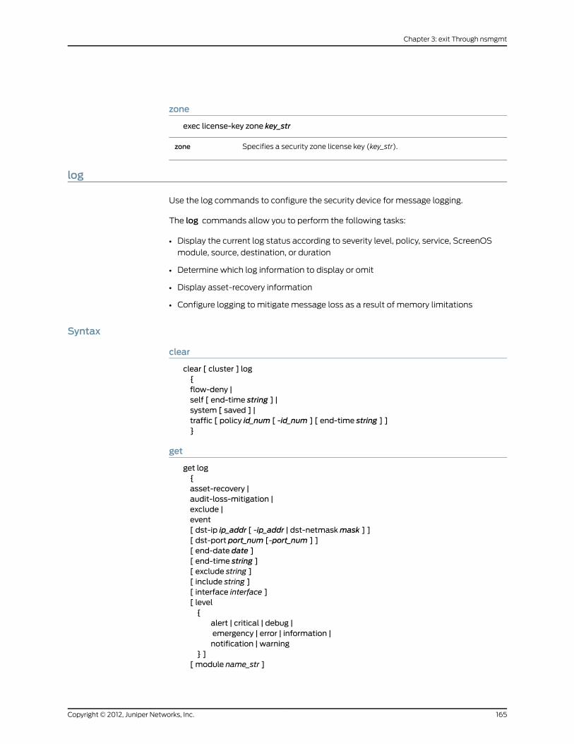
zone
exec license-key zone key_str
Specifies a security zone license key (key_str).zone
log
Use the log commands to configure the security device for message logging.
The log commands allow you to perform the following tasks:
• Display the current log status according to severity level, policy, service, ScreenOS
module, source, destination, or duration
• Determine which log information to display or omit
• Display asset-recovery information
• Configure logging to mitigate message loss as a result of memory limitations
Syntax
clear
clear [ cluster ] log{flow-deny |self [ end-time string ] |system [ saved ] |traffic [ policy id_num [ -id_num ] [ end-time string ] ]}
get
get log{asset-recovery |audit-loss-mitigation |exclude |event[ dst-ip ip_addr [ -ip_addr | dst-netmaskmask ] ][ dst-port port_num [-port_num ] ][ end-date date ][ end-time string ][ exclude string ][ include string ][ interface interface ][ level{
alert | critical | debug |emergency | error | information |notification | warning
} ][ module name_str ]
165Copyright © 2012, Juniper Networks, Inc.
Chapter 3: exit Through nsmgmt

[ policy { pol_num1 [ -pol_num2 ] } ][ protocol protocol 1 [ -protocol2 ] ][ sort-by
{date | dst-ip | dst-port |interface | policy | src-ip |user-name | time} ]
[ src-ip ip_addr [ -ip_addr | src-netmaskmask ] ][ start-date string ][ start-time string ][ type id_num [ -id _num ] ] |flow-deny |self | traffic [ policy pol_num [ -pol_num ] ][ start-date date [ time ] ] [ end-date date ] [ time ] ][ start-time string ] [ end-time string ][ min-duration string ] [ max-duration string ][ service name_str ][ src-ip ip_addr [ -ip_addr ][ src-netmaskmask ] [ src-port port_num ]
][ dst-ip ip_addr [ -ip_addr ] [ dst-netmaskmask ] ][ dst-port port_num ][ no-rule-displayed ] |
sort-by{date [ [ start-date date [ time ] ] [ end-date date [ time ] ] ]dst-ip [ ip_addr [ -ip_addr | dst-netmaskmask ] ]src-ip [ ip_addr [ -ip_addr | src-netmaskmask ] ]time[ start-time time ][ end-time time ]
}setting [ module { system | all } ]}
set
set log{audit-loss-mitigation |cli { enable | file-size number } |
exclude-idnumber [ user-idname_str ] [ event-typenumber ] [src-ip ip_str ] [ dst-ip ip_str] [ dst-port number ] [success | failure ] |module name_str level string destination string}
Keywords and Variables
audit-loss-mitigation
get log audit-loss-mitigationset log audit-loss-mitigation
Copyright © 2012, Juniper Networks, Inc.166
IPv6 Command Descriptions

unset log audit-loss-mitigation
Stops generation of auditable events when the number of suchevents exceeds the capacity of the security device. Enabling thisfeature reduces the loss of event logs due to log overloads.
On some security devices, you must connect the syslog server tothe management interface on the Management Module. Thisensures that the syslog server is available if the audit trail fills upand network traffic stops.
audit-loss-mitigation
cli
set log cli { enable | file-size number }
Enables logging CLI activity. You can specify a limit in bytes for the size ofthe log.
cli
cluster
clear cluster log { ... }
Propagates the clear operation to all other devices in an NSRP cluster.cluster
event
get log event [... ]
Displays sorts, and searches the event log messages.
Directs the device to display event logs with the specified destination IPaddress or address range. The device can also sort event logs by destinationIP address.
dst-ip
Directs the device to exclude or include events containing a specified stringof characters (string).
include
exclude
Specifies the name of the interface that generated the event.Interface
Specifies the priority level of the event message. The priority levels are asfollows:
• emergency (Level 0) —The system is unusable.
• alert (Level 1)— Immediate action is necessary.
• critical (Level 2) —The event affects functionality.
• error (Level 3) —An error condition exists.
• warning (Level 4) —The event might affect functionality.
• notification (Level 5) —The event is a normal occurrence.
• information (Level 6) —The event generates general information aboutnormal operation.
• debug (Level 7) —The event generates detailed information fortroubleshooting purposes.
level
167Copyright © 2012, Juniper Networks, Inc.
Chapter 3: exit Through nsmgmt

Specifies the name of the system module that generated the event.module
Displays the log events for a policy specified by its ID number or for severalpolicies specified by a range of ID numbers. The ID number can be any valuebetween 0 and the total number of established policies. To define a range,enter the starting and ending ID numbers as follows: pol_num1-pol_num2
policy
Specifies the Transport layer protocol with which the event was generated.protocol
Sorts event logs by date, source IP address, destination IP address,destinationport, policy, protocol, user-name or time.
sort-by
Displays event logs by source IP address. The device can also display eventlogs with the specified source IP address or address range.
src-ip
Specifies the lower and upper ends of a range of times for an event. Whenyou specify a start-time and/or an endtime, the device sorts or filters the eventlogs based on the specified times, regardless of the date. The format is asfollows:
hh:mm:ss
start-time |end-time
Specifies the lower and upper ends of a range of times for an event. The formatis as follows:
mm/dd/yy-hh:mm:ss
You can omit the year (the current year is the default) or express the yearusing the last two digits or all four digits. The hour, minute, and second areoptional. The delimiter between the date and the time can be a dash or anunderscore, as follows:
12/31/2001-23:59:00
12/31/2001_23:59:00
start-date |end-date
Specifies a priority level or a range of priority levels.type
exclude-id
set log exclude-id { ... }
Copyright © 2012, Juniper Networks, Inc.168
IPv6 Command Descriptions

unset log exclude-id number
Enables the security device to configure rules for excluding events from theaudit log. You can configure a maximum of 10 exclude rules.
• user-id—Indicates the authenticated user’s ID.
• event-type—Indicates the event or log type number.
• src-ip—Indicates the source IPv6 address of the authenticated user.
• dst-ip—Indicates the destination IPv6 address of the authenticated user.
• dst-port—Indicates the destination port number of the authenticated user.
• success—Indicates the event result as a success.
• failure—Indicates the event result as a failure.
exclude-id
Example: The following command instructs the security device to create an exclude rule
to exclude events with similar fields from being generated in the audit log:
set log exclude-id 1 user-id 23 event-type 1 src-ip 10.10.10.10 dst-ip 20.20.20.20dst-port 24 success
flow-deny
get log flow-denyclear log flow-deny
Displays log details for packets dropped by the security device. You can clearthe log details by using the clear log flow-deny command.
Note: By default, the security device does not log the dropped packet details.You can enable this feature by using the set flow log-dropped-packetcommand. You should enable this feature only for debug purposes.
flow-deny
destination
set logmodule name_str level string destination stringunset logmodule name_str level string destination string
Specifies the destination of the generated log messages. The permissibledestinations areconsole, internal,email,snmp,syslog,webtrends,onesecure,and pcmcia.
destination
Example: The following command instructs the security device to direct all system
module messages at the alert level (or higher) to the console port.
set logmodule system level alert destination console
dst-port
get log traffic dst-port number
Filters the output of the get log command by a range of destination portnumbers or by a specific destination port number.
dst-port
Example: The following command filters the get traffic log output to display only traffic
destined for port 80 (that is, HTTP traffic):
169Copyright © 2012, Juniper Networks, Inc.
Chapter 3: exit Through nsmgmt

get log traffic dst-port 80
level
set logmodule name_str level string destination stringunset logmodule name_str level string destination string
Specifies the minimum urgency level of the generated log messages. Startingwith the most urgent, these levels areemergency,alert,critical,error,warning,notification, information, and debugging. For the get log command, theall-levels option displays all security levels.
level
Example: The following command instructs the security device to direct all system
module messages at the critical level (or higher) to the email server:
set logmodule system level critical destination email
min-duration | max-duration
get log event { ... } [ ... ] min-duration string [ ... ]get log event { ... } [ ... ] max-duration string [ ... ]
Displays traffic log entries for traffic whose duration was longer than or equalto the minimum duration specified.
min-duration
Displays traffic log entries for traffic whose duration was shorter than or equalto the maximum duration specified.
max-duration
Example: The following command displays traffic log entries for traffic that lasted 5
minutes to 1 hour:
get log traffic min-duration 00:05:00max-duration 01:00:00
module
get log event module { ... } [ ... ]set logmodule name_str { ... }unset logmodule name_str { ... }
Specifies the name of the ScreenOS module that generates the log message.module
Example: The following command instructs the security device to direct all system
module messages at the critical level (or higher) to the Webtrends server:
set logmodule system level critical destination webtrends
no-rule-displayed
get log { ... } [ ... ] no-rule-displayed
Displays traffic log entries, but does not display policy information.no-rule-displayed
Example: The following command displays traffic log entries without displaying policy
information:
Copyright © 2012, Juniper Networks, Inc.170
IPv6 Command Descriptions

get log traffic no-rule-displayed
policy
clear [ cluster ] log traffic policy pol_num [ ... ]
Displays traffic log entries for a policy (specified by its ID number) or for severalpolicies (specified by a range of ID numbers). The ID number can be any valuebetween 0 and the total number of established policies. To define a range,enter the starting and ending ID numbers using this syntax:pol_num - pol_num
policy
Example: The following command displays traffic log table entries for any policy with
ID 3 to 9 (inclusive):
get log traffic policy 3-9
self
clear [ cluster ] log self [ ... ]get log self [ ... ]
Clears or displays self-log entries from the log.self
Example: The following command displays traffic log table entries for any policy with
a source IP address of 172.16.10.1 and a destination address of 172.16.10.100:
get log self src-ip 172.16.10.1 dst-ip 172.16.10.100
service
get log { ... } [ ... ] service name_str [ ... ]
Displays traffic log entries for a specified service, such as TCP, ICMP, FTP, orAny. The name does not have to be complete; for example, both TC and CPare recognized as TCP. Although you cannot specify a service group, TP isrecognized as FTP,HTTP, and TFTP, entering TP displays log entries for allthree services.
service
Example: The following command displays traffic log table entries for TCP:
get log self service tcp
setting
get log setting [ ... ]
Displays log setting information. Themodule string value specifies the nameof the module for which the log settings apply.
setting
Example: The following command displays traffic log settings for the system module:
get log settingmodule system
sort-by
get log { ... } sort-by date [ [ start-date date ] [ end-date date ] ] [ time ]
171Copyright © 2012, Juniper Networks, Inc.
Chapter 3: exit Through nsmgmt

get log { ... } sort-by dst-ip [ ip_addr [ -ip_addr | dst-netmaskmask ] ]get log { ... } sort-by src-ip [ ip_addr [ -ip_addr | src-netmaskmask ] ]get log { ... } sort-by time [ start-time time ] [ end-time time ]
Sorts the log information by any of the following criterion.
• date | time Sorts the logs by date, time, or both.
The start-date option displays logs that occurred at or before the timespecified. The end-date option displays logs that occurred at or after thetime specified. The format for start-date and end-date date ismm/dd[yy-hh:mm:ss]. The format forstart-timeandend-time ishh:mm:ss.
You can omit the year (the current year is the default), or express the yearusing the last two digits or all four digits. The hour, minute, and second areoptional. The delimiter between the date and the time can be a dash or anunderscore:
12/31/2002-23:59:00
12/31/2002_23:59:00
• dst-ip Sorts the traffic logs by destination IP address.
• src-ip Sorts the traffic logs by source IP address.
sort-by
Example: The following command displays traffic log settings sorted by date and time:
get log traffic sort-by date start-date 11/21/2003-22:24:00
src-ip | dst-ip
get log { ... } [ ... ] src-ip ip_addr [ -ip_addr ] [ ... ]get log { ... } [ ... ] sort-by src-ip ip_addr [ -ip_addr ] [ ... ]get log { ... } [ ... ] dst-ip ip_addr [ -ip_addr ] [ ... ]get log { ... } [ ... ] sort-by dst-ip ip_addr [ -ip_addr ] [ ... ]
Displays traffic log entries for a specified source IP address or range of sourceIP addresses. Include the subnet mask for a source IP address to display trafficentries for all IP addresses in the same subnet as the specified source IPaddress. You cannot specify a source IP range and a source subnet masksimultaneously. You can also direct the device to sort event logs by source IPaddress.
src-ip
Displays traffic log entries for a specified destination IP address or range ofdestination IP addresses. You can specify the subnet mask for a destinationIP address, but you cannot specify a destination IP range and destinationsubnet mask simultaneously. You can also direct the device to sort event logsby destination IP address.
dst-ip
Example:The following command displays traffic log entries for the range of destination
IP addresses 172.16.20.5–172.16.20.200:
get log traffic dst-ip 172.16.20.5-172.16.20.200
src-port
get log { ... } [ ... ] src-port port_num [ ... ]
Displays traffic log entries for a specified port number or range of source portnumbers.
src-port
Copyright © 2012, Juniper Networks, Inc.172
IPv6 Command Descriptions

Example:The following command displays traffic log entries from the source port 8081:
get log traffic src-port 8081
start-date | end-date
get log { ... } [ start-date date [ time ] ] [ end-date date [ time ] ]get log { ... } sort-by date [start-date date [ time ] ] [end-date date [ time ] ]
Specifies the lower and upper ends of a range of dates for traffic or self logs.You can omit the year (the current year is the default), or express the yearusing the last two digits or all four digits. The hour, minute, and second areoptional. The delimiter between the date and the time can be a dash or anunderscore:
12/31/2001-23:59:00
12/31/2001_23:59:00
start-date date[ time ]
end-date date[ time ]
start-time | end-time
get log { ... } [ start-time time ] [ end-time time ]get log { ... } sort-by [ start-time time ] [ end-time time ]
Specifies the lower and upper ends of a range of times for traffic or self logs.When you specify a start-time and/or end-time, the device sorts or filters thelogs based on the specified times, regardless of the date. Specify the time inthe following format: hh:mm:ss
start-timeend-time
Example: The following command displays event log entries from 3:00 P.M. on March
4, 2001 to 2:59:59 P.M. on March 6:
get log event start-time 03/04/01_15:00 end-time 03/06_14:59:59
system
clear [ cluster ] log system [ ... ]get log system [ reversely | saved ]
Displays current system log information. The saved switch displays savedsystem log information. The reversely switch displays information in reverseorder.
system
Example: The following command generates log messages generated from module
system, and to generate only messages that are critical or greater:
set logmodule system level critical destination console
traffic
clear [ cluster ] log traffic [ ... ]get log traffic [ ... ]
Specifies traffic log entries.traffic
173Copyright © 2012, Juniper Networks, Inc.
Chapter 3: exit Through nsmgmt

Example: The following command displays traffic log entries from the source port 8081:
get log traffic src-port 8081
mac
Use themac commands to configure a static Media Access Control (MAC) address for
a Juniper Networks interface or to display information about the current MAC
configurations.
NOTE: You can only execute themac commands when the device isconfigured in transparent mode.
Syntax
set
set macmac_addr interface
get
get mac interface
Keywords and Variables
Variables
Specifies the MAC address.mac_addr
Specifies the name of the interface, as with ethernet1.interface
Example: The following command sets the MAC address on an security device to
111144446666 for the ethernet7 interface:
setmac 111144446666 ethernet7
mac-learn
Use themac-learn commands to clear the entries in the Media Access Control (MAC)
learning table, or to display information about the current MAC configurations.
This command functions only when an interface is in transparent mode. When interfaces
are in transparent mode, the security device operates at Layer 2. The security zone
interfaces do not have IP addresses, and the security device forwards traffic like a Layer
2 switch.
Syntax
clear
clear [ cluster ] mac-learn [ stats ]
Copyright © 2012, Juniper Networks, Inc.174
IPv6 Command Descriptions

get
get mac-learn [ interface ]
Keywords and Variables
Variables
get mac-learn interface
Identifies the interface.interface
cluster
clear cluster mac-learn [ ... ]
Propagates the clear operation to all other devices in an NSRP cluster.cluster
stats
clear [ cluster ] mac-learn stats
Clears the MAC learning table statistics.stats
management-vroute
Use themanagement-vroute command to create a virtual router (VR) dedicated to
management.
A management (MGT) VR supports the out-of-band management infrastructure and
segments firewall management traffic away from production traffic. By default, the
ScreenOS TCP/IP stack first looks up routes for the self-initiated traffic in the default
VR, and if routes are not found, it searches the route table in untrust-vr. When you
designate a VR as a MGT VR, the TCP/IP stack looks up the routes in the MGT VR.
A MGT VR is valid in the root virtual system (vsys) only. A MGT VR is also not valid at
Layer 2, because a virtual local area network (VLAN) interface at Layer 2 cannot be
moved to another VR other than the trust-VR.
Syntax
set management-vroute vr_name
Keywords and Variables
Variables
set management-vroute vr_nameunset management-vroute
Specifies the virtual router to be set as the MGT VR.vr_name
Example: The following command sets a VR named trust2-vr as the management VR:
175Copyright © 2012, Juniper Networks, Inc.
Chapter 3: exit Through nsmgmt
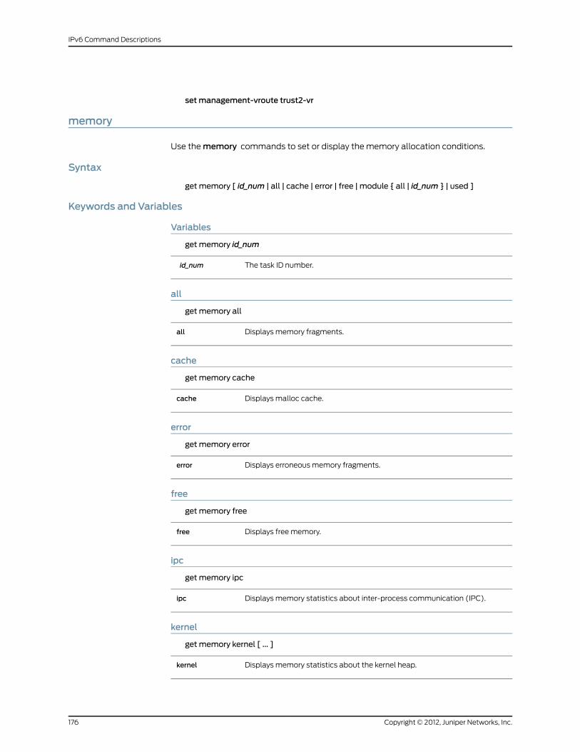
setmanagement-vroute trust2-vr
memory
Use thememory commands to set or display the memory allocation conditions.
Syntax
get memory [ id_num | all | cache | error | free | module { all | id_num } | used ]
Keywords and Variables
Variables
get memory id_num
The task ID number.id_num
all
get memory all
Displays memory fragments.all
cache
get memory cache
Displays malloc cache.cache
error
get memory error
Displays erroneous memory fragments.error
free
get memory free
Displays free memory.free
ipc
get memory ipc
Displays memory statistics about inter-process communication (IPC).ipc
kernel
get memory kernel [ ... ]
Displays memory statistics about the kernel heap.kernel
Copyright © 2012, Juniper Networks, Inc.176
IPv6 Command Descriptions

module
get memorymodule id_num
Displays a single memory module (id_num).module
pool
get memory pool
Displays pooled memory.pool
used
get memory used
Displays used memory.used
mirror
Use themirror commands to mirror all traffic for at least one source interface to a
destination interface. This command is useful for debugging and monitoring network
traffic. For example, you can connect a sniffer to a destination interface to monitor traffic
passing through multiple source interfaces.
NOTE: When a destination interfacemirrors multiple source interfaces, thedevicemay drop some frames due to a bandwidthmismatch.
Syntax
get
get mirror port
set
set mirror port source interface1 destination interface2
Keywords and Variables
destination | source
set mirror port source interface1 destination interface2
Specifies the source and destination interfaces.destination
ndp
Use thendpcommand to list neighbor discovery (ND) entries in the neighbor cache table
or create an entry in the table.
177Copyright © 2012, Juniper Networks, Inc.
Chapter 3: exit Through nsmgmt
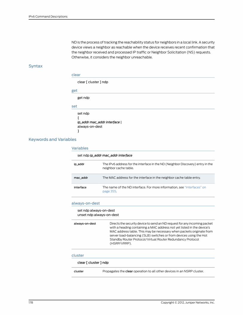
ND is the process of tracking the reachability status for neighbors in a local link. A security
device views a neighbor as reachable when the device receives recent confirmation that
the neighbor received and processed IP traffic or Neighbor Solicitation (NS) requests.
Otherwise, it considers the neighbor unreachable.
Syntax
clear
clear [ cluster ] ndp
get
get ndp
set
set ndp{ip_addr mac_addr interface |always-on-dest}
Keywords and Variables
Variables
set ndp ip_addr mac_addr interface
The IPv6 address for the interface in the ND (Neighbor Discovery) entry in theneighbor cache table.
ip_addr
The MAC address for the interface in the neighbor cache table entry.mac_addr
The name of the ND interface. For more information, see “Interfaces” onpage 355.
interface
always-on-dest
set ndp always-on-destunset ndp always-on-dest
Directs the security device to send an ND request for any incoming packetwith a heading containing a MAC address not yet listed in the device’sMAC address table. This may be necessary when packets originate fromserver load-balancing (SLB) switches or from devices using the HotStandby Router Protocol/Virtual Router Redundancy Protocol(HSRP/VRRP).
always-on-dest
cluster
clear [ cluster ] ndp
Propagates the clear operation to all other devices in an NSRP cluster.cluster
Copyright © 2012, Juniper Networks, Inc.178
IPv6 Command Descriptions

nsmgmt
Use the nsmgmt commands to set up a security device for configuration and monitoring
by Network and Security Manager (NSM), an enterprise-level management application
that configures multiple security devices from remote hosts.
The nsmgmt command can modify settings for two NSM components.
• The management system, a set of services that reside an external host (called a device
server). These services process, track, and store device management information.
• The Agent, a service that resides on the managed security device. The Agent receives
configuration parameters from the management system and pushes it to ScreenOS.
The Agent also monitors the device and transmits reports back to the management
system.
NOTE: We do not recommend using the nsmgmt command to initiatecommunicationbetweenNSMandtheNSMAgent.Themethodforperformingthis initiation differs depending upon the current availability of the securitydevice.
If your security device has a known, accessible IP address, you can set initialconfiguration parameters froma client through theNSMUI. You can also usethe UI if your device receives IP addresses dynamically, as with DHCP orPPPoE. If thedevice isnewanddoesnothaveaknown,accessible IPaddress,you can perform simple initial configuration by executing an encryptedconfiguration filecallConfiglet,whichautomaticallyexecutesseveralnsmgmtcommands. Your network security administrator creates the Configlet fileon theNSMUIanddelivers it to your remotesite, usuallymanuallyorbyemail.Formore information, see thediscussionaboutaddingdevices in theNetworkand Security Manager documentation athttp://www.juniper.net/techpubs/software/management/security-manager.
Syntax
get
get nsmgmt[proto-dist{table { bytes | packets } |user-service}
]
set
set nsmgmt{
179Copyright © 2012, Juniper Networks, Inc.
Chapter 3: exit Through nsmgmt

enable |init{id string |installer name name_str password pswd_str |otp string} |
report{alarm { attack | di | other | traffic } enable |log { config | info | self | traffic } enable |proto-dist{enable |user-service svc_name { ah | esp | gre | icmp | ospf | tcp | udp }{ port_num1-port_num2 }
} |statistics { attack | ethernet | flow | policy } enable}
serverprimary | secondary{ name_str | ip_addr } [ port number ] [ src-interface interface ] |
}
Keywords and Variables
enable
get nsmgmt enableset nsmgmt enable
Enables remote management by initiating contact with the managementserver.
enable
init
get nsmgmt initset nsmgmt init id stringset nsmgmt init installer name name_str password pswd_strset nsmgmt init otp string
Sets initialization parameters for interaction with the management server.
• id string—An ID used (only once) during initiation of the connection betweenthe security device and the management server. The security device passesthe ID to the Management System to look up the One-Time Password inthe management database.
• installer name name_str password pswd_str—Specifies an installer nameand password, used (only once) during initiation of the connection betweenthe security device and the management server.
• otp string—Sets the One-Time Password (OTP). The security device usesthis password one time to contact the Security Management system. Afterinitiation of contact between the device and the management database,the device executes an unset command to erase the OTP.
init
Copyright © 2012, Juniper Networks, Inc.180
IPv6 Command Descriptions

keys
get nsmgmt keys
Displays information about the public and private keys used to encrypt anddecrypt the Configlet file.
keys
181Copyright © 2012, Juniper Networks, Inc.
Chapter 3: exit Through nsmgmt

report
set nsmgmt report { alarm | log | proto-dist | statistics } { ... }unset nsmgmt report { alarm | log | proto-dist | statistics } { ... }
Specifies which event messages the security device transmits to the server.
• alarm—Enables the transmission of alarm events. The categories of alarmsare as follows.
• attack—Transmits attack alarms such as syn-flag or syn-flood. For moreinformation about such attacks, see “interface” on page 118.
• di—Transmits attack alarms generated during Deep Inspection.
• traffic—Transmits traffic alarms.
• other—Transmits alarms other than attack, Deep Inspection, or trafficalarms.
The enable switch enables messaging for the specified alarm message.
log—Enables the transmission of log events. The categories of logs are asfollows.
• config—Transmits log messages for events triggered by changes in deviceconfiguration.
• info—Transmits low-level notification log messages about noncriticalchanges that occur on the device, as when an authentication procedurefails.
• self—Transmits log messages concerning dropped packets (such as thosedenied by a policy) and traffic that terminates at the security device (suchas administrative traffic). The self log displays the date, time, sourceaddress/port, destination address/port, duration, and service for eachdropped packet or session terminating at the security device.
• proto-dist— Sets or displays parameters for transmission of messagesconcerning protocol distribution parameters.
• enable—Enables transmission of protocol distribution messages to theserver.
• table—Displays the number of bytes or packets transmitted to theprotocol distribution table.
• user-service svc_name—Specifies messages generated by the followingservices.
• ah—Authentication Header service
• esp—Encapsulating Security Payload service
• gre—Generic Routing Encapsulation
• icmp—Internet Control Message Protocol
• ospf—Open Shortest Path First
• tcp—Transmission Control Protocol
• udp—User Datagram ProtocolThe port_num1-port_num2 setting specifies a range of port numbers.
report
Copyright © 2012, Juniper Networks, Inc.182
IPv6 Command Descriptions

• traffic—Transmits alarms generated while the device monitors and recordsthe traffic permitted by policies. A traffic log notes the following elementsfor each session:
• Date and time that the connection started
• Source address and port number
• Translated source address and port number
• Destination address and port number
• The duration of the session
• The service used in the session
The enable switch enables messaging for the specified log message.
• statistics—Enables the security device for reporting statistical informationto the server.
• attack—Enables transmission of messages containing attack statistics.
• ethernet—Enables transmission of messages containing ethernetstatistics.
• flow—Enables transmission of messages containing traffic flow statistics.
• policy—Enables transmission of messages containing policy statistics.The enable switch enables messaging for the specified statisticalmessage.
server
get nsmgmt serverset nsmgmt server { primary | secondary } { name_str | ip_addr } [ port number ]
Identifies the Security Management system server.server
183Copyright © 2012, Juniper Networks, Inc.
Chapter 3: exit Through nsmgmt

Copyright © 2012, Juniper Networks, Inc.184
IPv6 Command Descriptions

CHAPTER 4
ntp Through RIPng
This section lists and describes the ScreenOS command line interface (CLI) commands
ntp through RIPng.
NOTE: Certain commands and features are platform-dependent andmightbe unavailable on your Juniper Networks security product platform. Checkyour product datasheet for feature availability.
Click on a command for details:
• ntp on page 185
• os on page 188
• ospfv3 on page 189
• override on page 200
• patch on page 201
• performance on page 203
• ping on page 204
• pki on page 205
• policy on page 218
• port-mode on page 233
• pppoe on page 234
• proxy-id on page 240
• reset on page 241
• RIPng Commands on page 242
ntp
Use thentp command to configure the security device for Simple Network Time Protocol
(SNTP).
SNTP is a simplified version of NTP, which is a protocol used for synchronizing computer
clocks in the Internet. This version is adequate for devices that do not require a high level
185Copyright © 2012, Juniper Networks, Inc.

of synchronization and accuracy. To enable the SNTP feature, use the set clock ntpcommand.
Syntax
exec
exec ntp [ server { backup1 | backup2 | primary } ] update
get
get ntp
set
set ntp{auth { preferred | required } |interval number |max-adjustment number |no-ha-sync |server [ { backup1 | backup2 } { ip_addr | dom_name } ]key-id number preshare-key string |timezone number1 number2}
Keywords and Variables
auth
set ntp auth { preferred | required }
Configures an authentication mode to secure NTP traffic between the securitydevice and the NTP server.
• required—Specifies that the security device must authenticate all NTPpackets using the key id and preshared key information that the securitydevice and the NTP server previously exchanged out of band (the devicedoes not exchange the preshared key over the network).
• preferred—Specifies that the security device first must try to authenticateall NTP packets by sending out an update request that includesauthentication information—key id and checksum—same as for the Requiredmode. If authentication fails, the security device then sends out anotherupdate request without the authentication information.
Note: Before you can set an authentication mode, you must assign a keyid and preshared key to at least one of the NTP servers configured on thesecurity device.
auth
interval
set ntp interval numberunset ntp interval
Defines in minutes how often the security device updates its clock time bysynchronizing with the NTP server. The range for the synchronization intervalis from 1 to 1440 minutes (24 hours).
interval
Copyright © 2012, Juniper Networks, Inc.186
IPv6 Command Descriptions

Example:The following command configures the security device to synchronize its clock
time every 20 minutes:
set ntp interval 20
max-adjustment
set ntpmax-adjustment numberunset ntpmax-adjustment
Configures a maximum time adjustment value. This value represents themaximum acceptable time difference between the security device systemclock and the time received from an NTP server. When receiving a reply froman NTP server, the security device calculates the time difference between itssystem clock and the NTP server and updates its clock only if the timedifference between the two is within the maximum time adjustment valuethat you set.
max-adjustment
no-ha-sync
set ntp no-ha-syncunset ntp no-ha-sync
In a High Availability (HA) configuration, instructs the security device not tosynchronize its peer device with the NTP time update.
no-ha-sync
server
set ntp server { ip_addr | dom_name }set ntp server key-id number preshare-key stringset ntp server { backup1 | backup2 } { ip_addr | dom_name }set ntp server { backup1 | backup2 } key-id number preshare-key stringunset ntp server { ... }
• ip_addr The IPv4 or IPv6 address of the primary NTP server with which thesecurity device can synchronize its system clock time.
• dom_name The domain name of the primary NTP server with which thesecurity device can synchronize its system clock time.
• backup1 | backup2
• ip_addr The IPv4 or IPv6 address of the first (or second) backup NTPserver with which the security device can synchronize its system clocktime in case the primary server is not available.
• dom_nameThe domain name of the first (or second) backup NTP serverwith which the security device can synchronize its system clock time incase the primary server is not available.
• key-id number—Assigns a key id to the current server for authenticationpurposes
• preshare key —Assigns a preshared key to the current server forauthentication purposes.
• key-id number—Assigns a key id to the current server for authenticationpurposes.
• preshare key —Assigns a preshared key to the current server forauthentication purposes.
server
187Copyright © 2012, Juniper Networks, Inc.
Chapter 4: ntp Through RIPng

timezone
set ntp timezone number1 number2unset ntp timezone
Defines the Time Zone, expressed as an integer number1 between -12 and 12inclusive. A value of zero denotes GMT (Greenwich Mean Time). number2expresses minutes.
timezone
Example: The following command sets the Time Zone to Greenwich Mean time:
set ntp timezone 0
update
exec ntp update
Updates the time setting on a security device to synchronize it with the timesetting on an NTP server.
update
os
Use the os command to display kernel and task information for the operating system of
the security device.
Syntax
get os { cost | flow | kernel | misc | task name_str }
Keywords and Variables
cost
get os cost
Displays the amount of processor time used by elements of the operatingsystem.
cost
flow
get os flow
Displays flow statistics.flow
kernel
get os kernel
Displays kernel statistics.kernel
Copyright © 2012, Juniper Networks, Inc.188
IPv6 Command Descriptions

misc
get osmisc
Displays miscellaneous information.misc
task
get os task name_str
Displays information about a specified task (name_str).task
ospfv3
Use theospfv3 context to begin configuring Open Shortest Path First version 3 (OSPFv3)
routing protocol for a virtual router (VR).
Initiating the OSPFv3 context
Initiating the ospfv3 context can take up to four steps.
1. Enter the vrouter context by executing the set vrouter command.
set vrouter vrouter
For example:
set vrouter trust-vr
2. Set the router ID for this virtual routing instance.
device(trust-vr)-> set router-id { id_num | ip_addr }
3. Enter the ospfv3 context by executing the set protocol ospfv3 command.
device(trust-vr)-> set protocol ospfv3
4. Enable OSPFv3 (it is disabled by default).
device(trust-vr/ospfv3)-> set enable
Table 2 on page 189 shows the commands that are executable in the ospfv3 context.
Table 2: OSPFv3 Commands
OSPFv3 FunctionCommand
Use the area command to configure an area for an OSPFv3virtual routing instance.
An OSPFv3 area is a region that contains a collection of routersor virtual routing instances.
Command options: get, set, unset
“area” on page 191
189Copyright © 2012, Juniper Networks, Inc.
Chapter 4: ntp Through RIPng

Table 2: OSPFv3 Commands (continued)
Use the config command to display all commands executedto configure the OSPFv3 local virtual routing instance.
Command option: get
“config” on page 192
Use thedatabasecommand to display details about the currentOSPFv3 link state database.
Command option: get
“database” on page 193
Use the enable command to enable or disable OSPFv3 fromthe current routing instance.
Command options: set, unset
“enable” on page 194
Use the force-spf command to clear all the OSPFv3 routes andforce the routing instance to repopulate the routes withoutaltering the link-state databases.
Command option: clear
“force-spf” on page 195
Use the interface command to display all OSPFv3 interfaceson the VR.
Command option: get
“interface” on page 195
Use the neighbor command to display details about neighbordevices.
Command option: get
“neighbor” on page 195
Use the redistributecommand to import routes from a differentprotocol than the one used by the current virtual routinginstance.
The types of routing protocols from which to import routesinclude:
• Manually created routes (static)
• Routes from BGP (bgp)
• Routes that have at least one interface with an IP addressassigned to it (connected)
• Routes from RIPng (ripng)
• Routes that are discovered by the device (discovered)
• Routes that have already been imported (imported)
Command options: set, unset
“redistribute” on page 195
Use the routes-redistribute command to display details aboutroutes imported from a protocol other than OSPFv3.
Command option: get
“routes-redistribute” onpage 196
Copyright © 2012, Juniper Networks, Inc.190
IPv6 Command Descriptions

Table 2: OSPFv3 Commands (continued)
Use the rules-redistribute command to display conditions setfor routes imported from a protocol other than OSPFv3.
Command option: get
“rules-redistribute” on page 197
Use the statistics command to display information about Hellopackets, link state packets, database descriptions, ShortestPath First (SPF) packets, areas cleared, packets dropped, errors,and other traffic statistics related to the current OSPFv3 virtualrouting instance.
Command options: clear, get
“statistics” on page 197
Use the summary-import command to summarize a routeredistribution.
After importing a series of routes to the current OSPFv3 routinginstance from a router running a different protocol, you canbundle the routes into one generalized (or summarized) addressthat uses the same network stem of the prefix address. Bysummarizing multiple addresses, you allow the OSPFv3 routinginstance to treat a series of routes as one route, thus simplifyingthe process.
Command options: get, set, unset
“summary-import” on page 198
Use the vlink command to create a virtual link for the currentrouting instance.
A virtual link is a conveyance that allows two segments toconnect when the backbone router bridging them cannot reacheither segment.
Command options: get, set, unset
“vlink” on page 198
area
Use the area command to configure an area for an OSPFv3 virtual routing instance.
An OSPFv3 area is a region that contains a collection of routers or virtual routing instances.
Before you can execute the area command, you must initiate the ospfv3 context.
Syntax
get
get area [ id_num | ip_addr ]
set
set area { id_num | ip_addr }[metric-default-route number |no-summary |range ipv6_addr/prefix_length { advertise | no-advertise } |
191Copyright © 2012, Juniper Networks, Inc.
Chapter 4: ntp Through RIPng

stub }]
Keywords and Variables
Variable Parameters
get area [ id_num | ip_addr ]set area { id_num | ip_addr }unset area { id_num | ip_addr }
The IP address that identifies the area.ip_addr
The OSPFv3 area ID that identifies the area.id_num
metric-default-route
set area id_nummetric-default-route numberunset area id_nummetric-default-route number
Specifies the metric for the advertised default route. The default metric is 1.Enter a number between 1 and 65535.
metric-default-route
no-summary
set area id_num no-summaryunset area id_num no-summary
Prevents summary link-state advertisements (LSAs) from being advertisedinto the area. By default, summary LSAs are advertised into the area.
no-summary
range
set area id_num range ipv6_addr/prefix_length { advertise | no-advertise }unset area id_num range ipv6_addr/prefix_length
Summarizes a specified range of IPv6 addresses in summary LSAs. You canspecify multiple ranges for the area. You can specify whether or not thesummarized addresses are advertised inside the area with the advertise andno-advertise keywords.
range
stub
set area id_num stubunset area id_num stub
Specifies the area as a stub area.stub
config
Use the config command to display all commands executed to configure the OSPFv3
local virtual routing instance.
Before you can execute the config command, you must initiate the ospfv3 context.
Copyright © 2012, Juniper Networks, Inc.192
IPv6 Command Descriptions

Syntax
get config
Keywords and Variables
None.
database
Use the database command to display details about the current OSPFv3 database.
Before you can execute the database command, you must initiate the ospfv3 context.
Syntax
get database[ detail ] [ area [ number | ip_addr ] ][ external | inter-area-prefix | inter-area-router | intra-area-prefix | link | network |
router[adv-router ip_addr |self-originate
][ link-state-id ip_addr ]
]
Keywords and Variables
adv-router
get database [ ... ] adv-router ip_addr [ ... ]
Displays LSAs from the specified advertising router (ip_addr).adv-router
area
get database [ ... ] area [ number | ip_addr ] [ ... ]
Displays LSAs in the current area.area
detail
get database detail [ ... ]
Displays detailed information.detail
external
get database [ ... ] external [ ... ]
Displays external LSAs.external
193Copyright © 2012, Juniper Networks, Inc.
Chapter 4: ntp Through RIPng

inter-area-prefix
get database { ... } inter-area-prefix
Displays inter-area-prefix LSAs only.inter-area-prefix
inter-area-router
get database { ... } inter-area-router
Displays inter-area-router LSAs only.inter-area-router
intra-area-prefix
get database { ... } intra-area-prefix
Displays intra-area-prefix LSAs only.intra-area-prefix
link-state-id
get database { ... } link-state-id ip_addr
Displays the LSA with a specified link-state ID (ip_addr).link-state-id
network
get database [ ... ] network [ ... ]
Displays network LSAs.network
router
get database [ ... ] router [ ... ]
Displays router LSAs.router
self-originate
get database [ ... ] self-originate [ ... ]
Displays self-originated LSAs.self-originate
enable
Use theenable command to enable or disable OSPFv3 from the current routing instance.
Before you can execute the set enable command, you must initiate the ospfv3 context.
Syntax
set enable
Keywords and Variables
None.
Copyright © 2012, Juniper Networks, Inc.194
IPv6 Command Descriptions

force-spf
Use the force-spfcommand to clear all the OSPFv3 routes and force the routing instance
to repopulate the routes without altering the link-state databases.
Before you can execute the force-spf command, you must initiate the ospfv3 context.
Syntax
clear force-spf
Keywords and Variables
None.
interface
Use the interface command to display all OSPFv3 interfaces on the VR.
Before you can execute the interface command, you must initiate the ospfv3 context.
Syntax
get interface
Keywords and Variables
None.
neighbor
Use the neighbor command to display details about neighbor devices.
Before you can execute the neighbor command, you must initiate the ospfv3 context.
Syntax
get neighbor
Keywords and Variables
None.
redistribute
Use the redistribute command to import known routes from a router running a different
protocol than the current virtual routing instance.
The types of routers from which to import routes include:
• Routers with manually created routes (static)
• Routers running BGP (bgp)
• Routers that have at least one interface with an IP address assigned to it (connected)
• Routers with routes that have already been imported (imported)
195Copyright © 2012, Juniper Networks, Inc.
Chapter 4: ntp Through RIPng

• Routers with the discovered routes (discovered)
• Routers running RIPng (ripng)
Before you can execute the redistribute command, you must initiate the ospfv3 context.
Syntax
get
get routes-redistribute [ summary ]get rules-redistribute
set
set redistribute route-map string protocol{ bgp | connected | discovered | imported | ripng | static }unset redistribute route-map { bgp | connected | discovered | imported | ripng | static }
Keywords and Variables
protocol
set redistribute route-map string protocol { ... }unset redistribute route-map name_str protocol { ... }
Specifies routing protocol. The route map can use the protocol type todetermine whether to forward or deny an incoming packet.
• bgp—Specifies that the route map performs an action only on BGP routesin the subnetwork.
• connected—Specifies that the route map performs an action only on routessent from a router that has at least one interface with an IP address assignedto it.
• discovered—Specifies that the route map performs an action only on routesdiscovered by the device.
• imported—Specifies that the route map performs an action only onimported routes in the subnetwork.
• ripng—Specifies that the route map performs an action only on RIPng routesin the subnetwork.
• static—Specifies that the route map performs an action only on staticroutes in the subnetwork.
protocol
route-map
set redistribute route-map string protocol { ... }unset redistribute route-map string protocol { ... }
Identifies the route map that indicates the path for which the route should beimported.
route-map
routes-redistribute
Use the routes-redistribute command to display details about routes imported from a
protocol other than OSPFv3.
Copyright © 2012, Juniper Networks, Inc.196
IPv6 Command Descriptions

Before you can execute the routes-redistribute command, you must initiate the ospfv3context.
Syntax
get routes-redistribute [ summary ]
Keywords and Variables
summary
get routes-redistribute [ summary ]
Shows the number of redistributed routes.summary
rules-redistribute
Use the rules-redistribute command to display conditions set for routes imported from
a protocol other than OSPFv3.
Before you can execute the rules-redistribute command, you must initiate the ospfv3context.
Syntax
get rules-redistribute
Keywords and Variables
None.
statistics
Use thestatisticscommand to display information about the following objects associated
with an OSPFv3 virtual routing instance:
• Hello packets
• Link state requests
• Link state acknowledgments
• Link state updates
• Database descriptions
• Areas created
• Shorted path first (SPF) runs
• Packets dropped
• Errors received
• Bad link state requests
Before you can execute the statistics command, you must initiate the ospfv3 context.
197Copyright © 2012, Juniper Networks, Inc.
Chapter 4: ntp Through RIPng

Syntax
get statistics
Keywords and Variables
None.
The following command removes all the statistics information associated with an OSPFv3
virtual routing instance:
clear statistics
summary-import
Use the summary-import command to summarize a route redistribution.
After importing a series of routes to the current OSPFv3 routing instance from a router
running a different protocol, you can bundle the routes into one generalized (or
summarized) address that uses the same network stem of the prefix address. By
summarizing multiple addresses, you allow the OSPFv3 routing instance to treat a series
of routes as one route, thus simplifying the process.
Before you can execute the summary-import command, you must initiate the ospfv3context.
Syntax
get
get summary-import
set
set summary-import ip ipv6_addr/prefix_length
Keywords and Variables
ip
set summary-import ip ipv6_addr/prefix_lengthunset summary-import ip ipv6_addr/prefix_length
The summarized prefix, consisting of an address (ipv6_addr) and a prefixlength (prefix_length) encompassing all the imported routes.
ip
vlink
Use the vlink command to create a virtual link for the current routing instance.
A virtual link is a conveyance that allows two segments to connect when the backbone
router bridging them cannot reach either segment.
Before you can execute the vlink command, you must initiate the ospfv3 context.
Copyright © 2012, Juniper Networks, Inc.198
IPv6 Command Descriptions

Syntax
get
get vlink
set
set vlink area-id { id_num1 | ip_addr } router-id { id_num2 | ip_addr }[dead-interval number |hello-interval number |retransmit-interval number |transit-delay number]
Keywords and Variables
area-id
set vlink area-id id_num1 { ... }unset vlink area-id id_num1 { ... }
Specifies the ID or IP address of the area through which the virtual link isconnected.
area-id
dead-interval
set vlink { ... } dead-interval numberunset vlink { ... } dead-interval number
Specifies the maximum amount of time (in seconds) that the security devicewaits, after it stops receiving packets from the neighbor, before classifyingthe neighbor as offline.
dead-interval
hello-interval
set vlink { ... } hello-interval numberunset vlink { ... } hello-interval number
Specifies the amount of time (in seconds) that elapses between instancesof the interface sending Hello packets to the network announcing the presenceof the interface.
hello-interval
retransmit-interval
set vlink { ... } retransmit-interval numberunset vlink { ... } retransmit-interval number
Specifies the amount of time (in seconds) that elapses before theinterface resends a packet to a neighbor that did not acknowledge aprevious transmission attempt for the same packet.
retransmit-interval
199Copyright © 2012, Juniper Networks, Inc.
Chapter 4: ntp Through RIPng

router-id
set vlink area-id id_num1 router-id id_num2unset vlink area-id id_num1 router-id id_num2
Specifies the ID of the router at the other end of the virtual link.router-id
transit-delay
set vlink { ... } transit-delay numberunset vlink { ... } transit-delay number
Specifies the amount of time (in seconds) that elapses before the securitydevice advertises a packet received on the interface.
transit-delay
override
Use the override command to override the following virtual system (vsys) parameters
(which are defined using the vsys-profile commands):
• CPU weight
• Sessions (maximum and reserved values and alarm threshold)
The override command is only available after you enter a vsys. By default, no override
values exist.
Syntax
get
get override [ cpu-weight | session-limit ]
set
set override{cpu-weight number |session-limit { alarm number | max number | reserve number}
Keywords and Variables
cpu-weight
get override [ cpu-weight ]set override cpu-weight numberunset override cpu-weight
CPU weight for the vsys. After entering the vsys, you can set an overridevalue for the CPU weight defined in the vsys profile.
Use the unset override cpu-weight command to remove the override. TheCPU weight configured in the vsys profile is now used.
cpu-weight
Copyright © 2012, Juniper Networks, Inc.200
IPv6 Command Descriptions

Example: The following commands first enter the vsys named hr and then override the
CPU weight to 30.
device->enter vsys hrdevice(hr)-> set override cpu-weight 30device(hr)->
session-limit
get override [ session-limit ]set override session-limit { alarm number | max number | reserve number }unset override session-limit { alarm |max | reserve }
Specifies session-limit override for the vsys:
• alarm—Specifies the percentage of the session limit at which an alarmis triggered. The alarm value is from 1 through 100 percent.
• max—Maximum number of sessions for the vsys. The configuredmaximum session value cannot exceed the absolute maximum valuefor the security device.
• reserve—Number of reserved sessions for the vsys when the securitydevice becomes oversubscribed. The reserved session value cannotexceed the maximum session value.
Use the unset override session-limit command to remove the override.The session-limit values configured in the vsys profile are now used.
session-limit
Example: The following commands first enter the vsys named hr and then override the
maximum number of sessions to 4000.
device-> enter vsys hrdevice(hr)-> set override session-limit max 4000device(hr)->
patch
Use the patch command to execute the commands for hot patch management.
Syntax
exec
exec patch [ activate | confirm | deactivate | load | remove ]
get
get patch
201Copyright © 2012, Juniper Networks, Inc.
Chapter 4: ntp Through RIPng

Keywords and Variables
activate
exec patch activate
Patches the image. This keyword changes the patch state from inactive(INACT) to active (ACT). Executing the activate command activates the newpatch.
Once the patch is activated, the device begins running the new version ofScreenOS. Resetting the device changes the state the INACT. This commandallows you to test the patch.
Before ScreenOS executes the patch, it runs a sanity check to ensure that itis safe to activate the patch. If this requirement is not met, the command failsand the patch is not activated. In such a case, you must retry the commandat a later time.
activate
confirm
exec patch confirm
• Changes the patch state from ACT to confirm (CFM). Useexecpatchconfirmto confirm the patch after you have tested it. Once you confirm the patch,it will not roll back when you reset the device. At that point, the only wayto roll back the software is to remove the patch.
confirm
deactivate
exec patch deactivate
• Rolls back the software image and changes the patch finite state machine(FSM) from ACT or CFM to INACT. This command is similar to exec patchactivate, in that ScreenOS first conducts a sanity check to ensure that it issafe to deactivate the patch. If this requirement is not met, the commandfails and the patch is not deactivated.
deactivate
load
exec patch load
• Changes the patch FSM from INIT to INACT. The hot patch file in flashmemory is loaded to memory. However, the device continues to run theolder software image.
load
Copyright © 2012, Juniper Networks, Inc.202
IPv6 Command Descriptions

remove
exec patch remove
• Changes the patch state to INIT and removes the patch from memory.However, the hot patch file remains in flash memory unless you delete itwith the delete file command.
The exec patch remove command is useful when you want to update to anewer hot patch file. However, because executing the remove option canseriously affect the system, ScreenOS first conducts a sanity check toensure that it is safe to remove the patch from memory. Unlike exec patchactivate/deactivate, exec patch remove has no corresponding commandthat will force the removal of the patch, since such an action might causea system crash.
remove
performance
Use the performance command to retrieve performance information for the security
device.
You can display information for the following:
• CPU utilization
• The session ramp-up rate
Syntax
get performance{cpu [ detail ] |cpu-limit [ detail [ vsys { vsys | all } ] ] |session [ detail ]}
Keywords and Variables
cpu
get performance cpu [ detail ]
cpu-limit
get performance cpu-limit [ detail [ vsys { name | all } ] ]
If the CPU limit feature is enabled, displays the CPU weights and configuredCPU quota percentage for all virtual systems. Also displays percentage ofCPU quota used for the last minute, the last 5 minutes, and the last 15 minutes.
• all displays detailed CPU limit performance information for all virtualsystems.
• detail displays CPU limit performance information for the last 60 seconds,the last 60 minutes, and the last 24 hours.
• vsys displays detailed CPU limit performance information for the specifiedvsys.
cpu-limit
203Copyright © 2012, Juniper Networks, Inc.
Chapter 4: ntp Through RIPng

session
get performance session [ detail ]
Displays the number of sessions added (ramp-up rate) for the last minute,the last 5 minutes, and the last 15 minutes. It does not display the total numberof sessions or the number of deleted sessions.
Displays the number of sessions added (ramp-up rate) for the last minute,the last 5 minutes, and the last 15 minutes. It does not display the total numberof sessions or the number of deleted sessions.
• detail displays session ramp-up rate for the last 60 seconds, the last 60minutes, and the last 24 hours.
session
ping
Use the ping command to check the network connection to another system.
An extended ping (using the from option) pings a host on the Untrusted network from
any existing MIP or from the Trusted interface IP address. The syntax for specifying a MIP
ismip ip_addr (see example in from keyword description).
Syntax
ping [ ip_addr | name_str ][ count number [ size number [ time-out number ] ] ] [ from interface ]name-lookup [ outgoing-interface ]
Keywords and Variables
Variables
ping [ ip_addr | name_str ] [ ... ]
Pings the host at an IPv4 or IPv6 address (ip_addr) or with name(name_str).
ip_addr | name_str
Example 1: The following command pings a host with IP address 172.16.11.2:
ping 172.16.11.2
Example 2: The following command pings a host with IPv6 address 3::200:ff:fe00:6:
ping 3::200:ff:fe00:6
count
ping [ ip_addr | name_str ] count number [ ... ]
The ping count (number).count
Example: The following command pings a device at 10.100.2.171 with a ping count of 3:
ping 10.100.2.171 count 3
Copyright © 2012, Juniper Networks, Inc.204
IPv6 Command Descriptions

from
ping [ ip_addr | name_str ] [ ... ] from interface
The source interface (interface) for an extended ping. For more information,see “Interfaces” on page 355.
Defines the source IP to which the ping will reply. Because this destination ison the untrusted side, the source IP can only be the mapped IP address or anuntrusted interface IP address.
from
Examples: The following command pings a device at 10.100.2.11 with a ping count of 4
from the ethernet1 interface:
ping 10.100.2.11 count 4 from ethernet1
The following command pings a host with IP address 192.168.11.2 and sends the results
to IP address 10.1.1.3:
ping 192.168.11.2 frommip 10.1.1.3
name-lookup
ping ip_addr name-lookup [ outgoing-interface ]
Uses the ICMP name to do a name lookup instead of using an echo request.
outgoing-interface automatically selects the outgoing interface to do thelookup.
name-lookup
size
ping [ ip_addr | name_str ] count number size number [ ... ]
The packet size (number) for each ping.size
time-out
ping [ ip_addr | name_str ] count number size number time-out number
The ping timeout in seconds (number).time-out
Example: The following command pings a device at 10.100.2.11:
• Ping count of 4
• Packet size 1000
• Ping timeout of 3 seconds
ping 10.100.2.11 count 4 size 1000 time-out 3
pki
Use the pki command to manage public-key infrastructure (PKI).
205Copyright © 2012, Juniper Networks, Inc.
Chapter 4: ntp Through RIPng

PKI refers to the hierarchical structure of trust required for public key cryptography. Using
PKI, the security device verifies the trustworthiness of a certificate by tracking a path of
certificate authorities (CAs) from the one issuing your local certificate back to a root
authority of a CA domain.
The pki commands perform the following tasks:
• Manage PKI objects.
• Create new RSA key pairs and acquire a certificate.
• Verify the certificate received from the communication peer.
• Acquire CRLs.
• Configure PKI-related operations, such as verification of certificate revocation.
Syntax
exec
exec pki{convert-cert |dsa new-key number [ & ] |rsa new-key number [ & ] |x509{install-factory-certs name_str |pkcs10 |scep{cert id_num |key { id_num | last-key } |renew id_num |} |
tftp ip_addr { cert-name name_str | crl-name name_str}
}
get
get pki{authority { id_num | default }{cert-path |cert-status |scep} |
ldap |pre-prime |src-interface |x509{cert id_num |cert-fqdn |
Copyright © 2012, Juniper Networks, Inc.206
IPv6 Command Descriptions

cert-path |crl-refresh |dn |list { ca-cert | cert |crl | key-pair | local-cert | pending-cert } |pkcs10 |raw-cn |send-to}
}
set (authority)
set pki authority { id_num | default }{cert-path { full | partial } |cert-status{crl{refresh { daily | default | monthly | weekly } |server-name { ip_addr | dom_name } |url url_str}
ocsp{cert-verify id id_num |not-verify-revoke |url url_str} |
revocation-check { crl [ best-effort ] | ocsp [ best-effort ] | none }}
scep{authentication { failed | passed } |ca-cgi string |ca-id name_str |challenge pswd_str |current |mode { auto | manual } |polling-int number |ra-cgi string |renew-start number}
}
set (ldap)
set pki ldap{crl-url url_str |server-name { name_str | ip_addr }}
set (pre-prime)
set pki pre-prime number
207Copyright © 2012, Juniper Networks, Inc.
Chapter 4: ntp Through RIPng

set (src-interface)
set pki src-interface interface
set (x509)
set pki x509{cert-fqdn string |default{cert-path { full | partial }crl-refresh { daily | default | monthly | weekly } |no-preload-ca |send-to string} |
dn{country-name name_str |domain-component string |email string |ip ip_addr |local-name name_str |name name_str |org-name name_str |org-unit-name name_str |phone string |state-name name_str} |
friendly-name string |raw-cn enable |renew id_num}
Keywords and Variables
authentication
set pki authority { ... } scep authentication { failed | passed } [ id_num ]
Sets the result of the CA certificate authentication, failed or passed. Theid_num value identifies a pending certificate created during a SCEP operation.
authentication
Example: The following command sets the result of a CA certificate authentication to
passed:
set pki authority default scep authentication passed
authority
get pki authority { id_num | default } { ... }set pki authority { id_num | default } { ... }
Copyright © 2012, Juniper Networks, Inc.208
IPv6 Command Descriptions

unset pki authority { id_num | default } { ... }
Defines how the security device uses the CA’s authorization services. Theid_num parameter is the identification number of the CA certificate.
Thedefault switch directs the device to use the authority configuration (usedwhen the CA certificate does not reside locally).
authority
Example: The following command instructs the security device to check for certificate
revocation on a daily basis:
set pki authority default cert-status crl refresh daily
cert-path
get pki authority { id_num | default } cert-pathset pki authority { id_num | default } cert-path { full | partial }unset pki authority id_num cert-path
Defines the X509 certificate path validation level.
When the device verifies a certificate, it builds a certificate chain fromcertificates received from the peer and the certificate stored locally.Certificates loaded locally are considered trusted.
• full—Directs the security device to validate the certificate chain to the root.(The last certificate in the certificate chain must be a self-signed CAcertificate.)
• partial—Specifies partial path validation. (The last certificate in thecertificate chain may be any locally stored certificate.)
In either case, the last certificate in the chain must come from local storage.You can set this certificate path validation level for a CA.
cert-path
Example: The following command defines the certificate path validation level as full:
set pki authority default cert-path full
cert-status
get pki authority { id_num | default } cert-statusset pki authority { id_num | default } cert-status { ... }
209Copyright © 2012, Juniper Networks, Inc.
Chapter 4: ntp Through RIPng

unset pki authority { id_num | default } cert-status { ... }
Defines how the security device verifies the revocation status of a certificate.
• crl—Configures Certificate Revocation List (CRL) parameters.
• refresh Determines how often (daily,monthly, orweekly) the securitydevice updates the CRL before the CRL expires. The default option usesthe validation date decided by the CRL.
• server-name { ip_addr:port_num | dom_name }—Specifies the server byIP address and port number, or by domain name.
• url url_str—Specifies the URL for accessing the CRL.
• ocsp—Configures Online Certificate Status Protocol (OCSP) parameters.
• cert-verify id number—Identifies the certificate to use when verifyingthe OCSP response.
• not-verify-revoke—Disables verification of revocation status on theOCSP signing certificate.
• url url_str—Specifies the URL for accessing the OCSP responder.
• revocation-check—Specifies how the security device checks certificatesto see if they are currently revoked.
• crl—Specifies that the device uses CRL to check certificate status.
• none—Specifies that the device does not perform a check of certificatestatus.
• ocsp—Specifies that the device uses OCSP to check certificate status.
• best-effort—Specifies that the device can use a certificate for which thereis no revocation information. This option is useful when CRL retrieval is notpractical. For example, in some environments the CRL server is onlyaccessible through a tunnel; however, the CRL information is necessary tobuild the tunnel originally. When you use the best-effort setting, it isadvisable to check the event log periodically. The device should accept acertificate without revocation information only when no revocationinformation is available. Repeatedly failing to get revocation informationfor a certificate usually indicates improper configuration.
cert-status
Example: The following command directs the security device to use the CRL to check
certificate status:
set pki authority default cert-status revocation-check crl
cert-verify id
set pki authority id_num1 cert-status ocsp cert-verify id id_num2unset pki authority id_num cert-status ocsp cert-verify
Identifies a locally stored certificate the security device uses to verify thesignature on an OCSP responder.
• id_num1—Identifies the CA certificate that issued the certificate beingverified.
• id_num2—Identifies the locally stored certificate the device uses to verifythe signature on the OCSP response.
cert-verify id
Copyright © 2012, Juniper Networks, Inc.210
IPv6 Command Descriptions

convert-cert
exec pki convert-cert
For ScreenOS versions earlier than 3.0.0, moves a local vsys certificate, whichhas an assigned vsys identifier, from the root to a specific vsys environment.
convert-cert
dsa new-key
exec pki dsa new-key number
Generates a new DSA public/private key pair with a specified bit length(number). Key length is 512, 786, 1024, or 2048.
dsa new-key
ldap
get pki ldapset pki ldap { ... }unset pki ldap { ... }
Specifies settings for the LDAP server, when the CA certificate associatedwith the server is not in the device.
• crl-url url_str—Sets the default LDAP URL for retrieving the certificaterevocation list (CRL).
• server-name { name_str | ip_addr:port_num }—Defines the fully qualifieddomain name or IP address and port number of the server.
ldap
Example: The following command assigns 162.128.20.12 as the server’s IP address:
set pki ldap server-name 162.128.20.12
pre-prime
get pki pre-primeset pki pre-prime number
211Copyright © 2012, Juniper Networks, Inc.
Chapter 4: ntp Through RIPng

unset pki pre-prime
The get command displays:
• The number of precalculated primes for every key type and key lengthcombination. The key type can be DSA or RSA and the key length can be1024 or 2048 bits depending on the device platform.Note: Juniper Networkssecurity appliances generate 1024-bit primes. Juniper Networks systemsgenerate 1024-bit and 2048-bit primes. For more information, see thedatasheet for your security device.
• The number of currently available pairs of prime numbers for every key typeand key length combination.
• Ongoing prime calculation for a key-type and key-length combination andthe number of attempts already made.
The set command instructs the security device to generate a specific numberof precalculated primes to store in memory.
The unset command reverts the security device to the default number ofprecalculated primes. The default number of precalculated primes isplatform-specific. For more information, see the datasheet for your securitydevice.
pre-prime
rsa new-key
exec pki rsa new-key number [ & ]
Generates a new RSA public/private key pair with a specified bit length(number). Key length is 512, 786, 1024, or 2048.
The& switch directs the device to perform key generation in the background,without waiting for the result. Without this switch, the device waits up to 100seconds.
rsa new-key
scep
exec pki x509 scep { cert id_num | key { id_num | last-key } | renew }get pki authority { id_num | default } scepset pki authority { id_num | default } scep { ... }
Copyright © 2012, Juniper Networks, Inc.212
IPv6 Command Descriptions

unset pki authority { id_num | default } scep { ... }
Defines Simple Certificate Enrollment Protocol (SCEP) parameters.
• authentication { passed | failed } [ id_num ] sets the result of the CAauthentication, failed or passed. The id_num value identifies a defined keypair.
• ca-cgi url_str—Specifies the path to the CA's SCEP server.
• ca-id string—Specifies the identity of the CA's SCEP server.
• cert-id id_num—Directs the security device to retrieve the final certificatefor a pending certification.
• challenge pswd_str—Specifies the Challenge password.
• current—Directs the security device to use the SCEP associated with a CAas default.
• key id_num—Directs the device to acquire a certificate for the specified keypair. The id_num parameter specifies the ID of a specific key pair. Thelast_key parameter specifies the most recently created key pair.
• mode {auto |manual }—Specifies the authentication mode to authenticatethe certificate.
• polling-int number Determines the retrieval polling interval (in minutes).The default value is 0 (none).
• ra-cgi url_str—Specifies the CGI path to the RA's SCEP server.
• renew id_num—Directs the device to renew the specified certificate(id_num).
• renew-start Set the number of days before the certificate expiration datewhen you want the security device to request the renewal of the certificate.
scep
Example: The following command sets the SCEP Challenge password to “swordfish” :
set pki authority default scep challenge swordfish
Example: The following command uses the SCEP setting for CA 123 as the default:
set pki authority 123 scep current
send-to
get pki x509 send-toset pki x509 default send-to stringunset pki x509 default send-to
Specifies or displays the email destination (string) to send the x509 certificaterequest file.
send-to
src-interface
get pki src-interfaceset pki src-interfaceunset pki src-interface
Displays, configures or removes the source interface the security device usesto send PKI traffic.
src-interface
213Copyright © 2012, Juniper Networks, Inc.
Chapter 4: ntp Through RIPng

x509
exec pki x509 { ... }get pki x509 { ... }
Copyright © 2012, Juniper Networks, Inc.214
IPv6 Command Descriptions

set pki x509 { ... }unset pki x509 { ... }
x509
215Copyright © 2012, Juniper Networks, Inc.
Chapter 4: ntp Through RIPng

Specifies settings for x509 certificates, displays certificate information, andperforms various operations related to x509 PKI object.
• cert id_num—Displays information about the specified certificate.
• cert-fqdn string—Configures the fully qualified domain name (FQDN). PKIuses this value in the certificate subject alt name extension.
• default—Specifies settings for the CA whose certificate is not locallyconfigured.
• crl-refresh—Sets or displays the refreshment frequency (daily,monthly,orweekly) of the X.509 CRL. Thedefaultoption uses the expiration datein each CRL.
• send-to string—Assigns the email address to which the security devicesends the PKCS10 certificate request file.
• dn—Specifies or displays the name that uniquely identifies a requestingcertificate.
• country-name name_str—Sets the country name.
• email string—Sets the email address.
• ip ip_addr—Sets the IPv4 or IPv6 address.
• local-name string—Sets the locality.
• name string—Sets the name in a common name field.
• org-name string—Sets the organization name.
• org-unit-name string—Sets the organization unit name.
• phone string—Sets a contact phone number as the X.509 certificate subjectname of the security device.
• state-name string—Sets the state name as the X.509 certificate subjectname.
• friendly-name name_str id_num A friendly name (name_str) for thecertificate (id_num).
• install-factory-certs name_str Loads a specified factory predefinedcertificate.
• list—Displays the X.509 object list.
• ca-cert—Displays all CA certificates.
• cert—Displays all X.509 certificates.
• key-pair—Displays all key pairs for which there is no certificate.
• crl—Displays all Certificate Revocation Lists (CRLs).
• local-cert—Displays all local certificates.
• pending-cert—Displays all pending certificates.
• pkcs10—Displays a PKCS10 file (an X.509 certificate request) for a keypair.
• raw-cnenable—Enables the raw common name (CN) or displays its currentstatus.
• scep
• cert id_num Initiates Simple Certificate Enrollment Protocol (SCEP)operation to retrieve certificates from a CA server. The id_numparameteris the identification number of the pending certificate.
• key { id_num | last-key } Initiates SCEP operation to obtain a certificatefor a key pair. The variable id_num identifies the key pair and last-keyspecifies to obtain a certificate for the most recently created key pair.
• renew id_num Initiates SCEP operation to renew an existing certificate.The variable id_num identifies the existing certificate to renew.
• tftp ip_addrUploads the specified certificate (cert-namename_str) or CRL
Copyright © 2012, Juniper Networks, Inc.216
IPv6 Command Descriptions

file (crl-name name_str) for the specified TFTP server at an IPv4 or IPv6address ip_addr.
Examples: The following command specifies the destination email address where the
security device sends the PKCS10 certificate request:
set pki x509 default send-to [email protected]
The following command refreshes the certificate revocation list on a daily basis:
set pki x509 default crl-refresh daily
The following command defines a distinguished name for Ed Jones, who works in
marketing at Juniper Networks in Sunnyvale, California:
set pki x509 dn country-nameUSset pki x509 dn state-name CAset pki x509 dn local-name Sunnyvaleset pki x509 dn org-name “ Juniper Networks”set pki x509 dn org-unit-namemarketingset pki x509 dn name “ Ed Jones”
Defaults
The RSA key length is set to 1024 bits.
Requesting a CA Certificate
You use the set pki, get pki, and exec pki command to request an x509 CA certificate
from a certificate authority. The following commands provide a typical example:
1. Specify a CA CGI path.
set pki auth default scep ca-cgi “ http://pilotonsiteipsec.verisign.com/cgi-bin/pkiclient.exe”
NOTE: TheCommonGateway Interface (CGI) is a standardway for aWebserver to pass a user request to an application program, and to receivedata back. CGI is part of Hypertext Transfer Protocol (HTTP).
2. Specify a registration authority RA CGI path
set pki auth default scep ra-cgi “ http://pilotonsiteipsec.verisign.com/cgi-bin/pkiclient.exe”
NOTE: Youmust specify an RA CGI path even if the RA does not exist. Ifthe RA does not exist, use the value specified for the CA CGI.
3. Generate an RSA key pair, specifying a key length of 1024 bits.
exec pki rsa new 1024
4. Initiate the SCEP operation to request a local certificate.
217Copyright © 2012, Juniper Networks, Inc.
Chapter 4: ntp Through RIPng

exec pki x509 scep key last-key
5. If this is the first attempt to apply for a certificate from this CA, a prompt appears
presenting a fingerprint value for the CA certificate. (Otherwise, go to step 6.)
After verification of the fingerprint, allow the operation to continue by executing the
following command:
set pki auth default scep auth passed
You must specify an RA CGI path even if the RA does not exist. If the RA does not exist,
use the value specified for the CA CGI.
6. If the device does not approve the certificate automatically, contact your CA
administrator to approve the local certificate request.
7. (Optional) Display a list of pending certificates. This allows you to see and record the
ID number identifying the pending certificate.
get pki x509 list pending-cert
8. (Optional) Obtain the local certificate from the CA (using the ID number obtained in
step 7) to identify the certificate. In this example, the certificate number is 1001.
exec pki x509 scep cert 1001
policy
Use thepolicy command to define policies to control network and virtual private network
(VPN) traffic.
A policy is a set of rules that determines how traffic passes between security zones
(interzone policy), between interfaces bound to the same zone (intrazone policy), and
between addresses in the Global zone (global policy). When a security device attempts
to pass a packet from one zone to another, between two interfaces bound to the same
zone, or between two addresses in the Global zone, the security device checks its policy
lists for a policy to permit such traffic. For example, to allow traffic to pass from one
security zone to another, you must configure a policy that permits zone A to send traffic
to zone B. To allow traffic originating in zone B to flow to zone A, you must configure
another policy permitting traffic from zone B to zone A.
Executing the set policy id pol_num command without specifying further options places
the CLI within the context of an existing policy. For example, the following commands
define a policy with ID number 1 and then enter the policy:1 context to add a second
service:
device-> set policy id 1 from trust to untrust host1 host2 HTTP permitdevice-> set policy id 1device(policy:1)-> set service FTP
After you enter a policy context, all subsequent command executions modify the specified
policy (policy:1 in this example). To save your changes, you must first exit the policy
context, and then enter the save command:
device(policy:1)-> exit
Copyright © 2012, Juniper Networks, Inc.218
IPv6 Command Descriptions

device-> save
You can also use the set policy id pol_num command with additional options to modify
an existing policy. For example, the following commands add a Deep Inspection extension
to policy 1:
device-> set policy id 1 from trust to untrust host1 host2 HTTP permitdevice-> set policy id 1 attack HIGH:HTTP:SIGS action close
NOTE: The above example adds a deep inspection (DI) extension that wasnot present in the original policy. After you enter a policy context, you cannotadd a DI extension if one does not already exist in the original policy.
Syntax
exec
get
get policy{disabled |[ from zone1 ] |[ to zone2 ] |[ [ src-ip ip_addr ] | [ src-address addr_name ] ] |[ [ dst-ip ip_addr ] | [ dst-address addr_name ] ] |[ [ action { deny | permit | reject | tunnel | av | idp | uf } ] | service svc_name ] |[ id pol_num [ sess-limit count [ src-ip ip_addr ] ] ] |[ all ] |[ global [id pol_num [ sess-limit count [ src-ip ip_addr ] ] ]}
get (Within a Policy Context)
get configuration
set
set policy{[ global ][ id pol_num1 ][ top | before pol_num2 ][ name name_str ][ from zone1 to zone2 ]src_addr dst_addr svc_name[nat[ src [ dip-id id_num ] ][ dst ip addr1 [ addr2 | port port_num ] ]
]{permit |tunnel { l2tp tunn_str | vpn-group id_num } |tunnel vpn tunn_str [ l2tp tunn_str | pair-policy pol_num ]
219Copyright © 2012, Juniper Networks, Inc.
Chapter 4: ntp Through RIPng

}[ no-hw-sess ][ notify-conn-close ] |[ auth [ server name_str ] | webauth ][group-expression string |user name_str | user-group name_str]
] |deny[ schedule name_str ][ log [ alert ] ][ count [ alarm id_num1 id_num2 ] ][ no-session-backup ]
[ url-filter ][traffic { gbw number }{ priority number }{mbw [ number ]dscp { disable | enable }}
][ attack string action string | av name_str ]
}set policy move pol_num1 { before pol_num2 | after pol_num3 }set policy default-permit-all
set policy id number
set policy [ global ] id pol_num disableset policy [ global ] id pol_num application svc_nameset policy [ global ] id pol_num attack string action stringset policy [ global ] id pol_num av name_str
set (Within a Policy Context)
set{attack string |av name_str |count [ alarm number1 number2 ] |di-alert-disable |di-severity { info | low | medium | high | critical } |dst-address | src-address{ name_str | negate } |
log [ alert ] |name name_str |no-hw-sess |[ notify-conn-close ] |service svc_name |src-address { name_str | negate }}
unset (Within a Policy Context)
unset attack string
Copyright © 2012, Juniper Networks, Inc.220
IPv6 Command Descriptions

unset av name_strunset countunset { dst-address | src-address } { name_str | negate }unset { ims-alert | ims-log }unset logunset nameunset service svc_nameunset severity
Keywords and Variables
action
get policy [ action { deny | permit | reject | tunnel | av | idp | uf } ]
Displays information about security policies set to the specified action (deny,permit, reject, tunnel, av, idp, or uf).
action
all
get policy [ all ]
Displays information about all security policies, including global policies.all
application
set policy [ global ] id pol_num application svc_name
Defines the type of Layer 7 application associated with a Layer 3 service andLayer 4 port number. This is particularly important for defining the Layer 7application for custom services so that the security device can properly inspectsuch traffic for attack signatures and anomalies.
The ignoreoption, which appears near the end of the list of application choices,instructs the security device to ignore the application type typically associatedwith a predefined service and port number. Using the ignore option instructsthe security device not to scan the packet payload and can prevent the securitydevice from attempting to parse one type of traffic when it is actually anothertype—such as the case with LDAP and H.323 traffic, both of which use TCPport 389.
The none option, which also appears near the end of the list of applicationchoices, instructs the security device to use the default setting. Choosingnoneis equivalent to entering the unset policy id pol_num application command.
application
Example: The following command identifies the Layer 7 application for policy ID 1 as FTP:
set policy id 1 application FTP
attack
set policy { … } attack string action stringset attack stringunset policy { pol_num | id pol_num } attack
221Copyright © 2012, Juniper Networks, Inc.
Chapter 4: ntp Through RIPng

unset attack string
Inspects traffic to which the policy applies for attack objects in the specifiedattack object group. Attack objects can be stateful signatures or protocolanomalies. If the security device detects an attack object, it then performsthe specified action, which can be one of the following:
• Close—Logs the event, severs the connection, and sends TCP RST packetsto both the client and server.
• CloseClient—Logs the event, severs the connection, and sends a TCP RSTpacket to the client.
• CloseServer—Logs the event, severs the connection, and sends a TCP RSTto the server.
• Drop—Logs the event and severs the connection without sending eitherthe client or the server TCP RST packets.
• Drop packet—Logs the event and drops the packet containing the attackobject, but it does not sever the connection.
• Ignore—Logs the event and stops checking—or ignores—the remainder ofthe connection.
• None—Logs the event but takes no action.
attack string
Example: The following commands define a policy to check for attack objects in the
CRITICAL:HTTP:ANOM, CRITICAL:HTTP:SIGS, HIGH:HTTP:ANOM, and HIGH:HTTP:SIGS
attack object groups in HTTP traffic from any host in the Untrust zone to webserver1 in
the DMZ zone. If the security device detects any attack objects, it then severs the
connection and sends webserver1 a TCP RST so it can clear its resources:
device-> set policy id 1 from untrust to dmz any webserver1 http permit attack
CRITICAL:HTTP:ANOM action close serverdevice-> set policy id 1device(policy:1)-> set attack CRITICAL:HTTP:SIGSdevice(policy:1)-> set attack HIGH:HTTP:ANOMdevice(policy:1)-> set attack HIGH:HTTP:SIGS
auth
set policy { ... } auth [ ... ]
Requires the user to provide a login name and password to authenticate hisor her identity before accessing the device and crossing the firewall.
• server name_str—Identifies the authentication server (name_str).
• group-expression string—Identifies users according to an expression(string).
• user name_str—Identifies a user (name_str).
• user-group name_str—Identifies a user group (name_str).
auth
Example: The following command invokes user authentication.
• Permits any kind of traffic from any address in the Trust zone to any address in the
Untrust zone
• Uses an authentication server namedwc-server
Copyright © 2012, Juniper Networks, Inc.222
IPv6 Command Descriptions

set policy from trust to untrust any any any permit auth server wc-server
before
set policy before pol_num1 { ... }
Specifies the position of the policy before another policy (pol_num) in theaccess control list (ACL).
before
Example: The following command creates a new policy with ID number 3 and positions
it before the policy with ID number 2:
set policy id 3 before 2 from trust to untrust any any any permit
configuration
get configuration
Displays the configuration details for the policy in whose context you issuethe get configuration command.
configuration
count
set policy { ... } [ count [ alarm { id_num1 id_num2 } ] ] { ... }
Maintains a count, in bytes, of all the network traffic the policy allows to passthrough the security device.
The alarm number1 number2 parameter enables the alarm feature so thatyou can view alarms. You must enter the number of bytes per second(number1) and the number of bytes per minute (number2) required to triggeran alarm.
count
Example: The following command permits any kind of traffic from any address in the
Trust zone to any address in the Untrust zone and maintains a count of all network traffic
to which the policy applies:
set policy from trust to untrust any any any permit count
default-permit-all
set policy default-permit-all
Allows access without checking the access control list (ACL) for amatching policy.
default-permit-all
223Copyright © 2012, Juniper Networks, Inc.
Chapter 4: ntp Through RIPng

deny | nat | permit | reject | tunnel
set policy [ global ] { ... } | deny | nat | permit | reject | tunnel | [ ... ]
• deny—Blocks the service at the firewall. The security device simplydrops the packet.
• nat—Enables Network Address Translation.
• permit—Allows the specified service to pass from the sourceaddress across the firewall to the destination address.
• reject—Blocks the service at the firewall. The security devicedrops the packet and sends a TCP reset (RST) segment to thesource host for TCP traffic and an ICMP “ destination unreachable,port unreachable” message (type 3, code 3) for UDP traffic. Fortypes of traffic other than TCP and UDP, the security device dropsthe packet without notifying the source host, which is also whatoccurs when the action is deny.
• tunnel—Allows you to use VPN or IPSEC tunnel.
deny | nat | permit | reject |tunnel
Example: The following command:
• Defines a policy from the Trust zone to the Untrust zone
• Uses any source or destination IP address
• Permits any kind of service
set policy from trust to untrust any any any permit
di-alert-disable (within a policy context)
set di-alert-disable
Disables DI (Deep Inspection) alert generation.di-alert-disable
disable
set policy [ global ] id pol_num disableget policy disabled
Disables a policy without removing it from the configuration. The get commanddisplays all disabled policies.
disable
di-severity (within a policy context)
set di-severity { info | low | medium | high | critical }
Specifies the severity of events that generate error messages. The possibleevent levels are info, low,medium, high, and critical.
di-severity
Copyright © 2012, Juniper Networks, Inc.224
IPv6 Command Descriptions

dst-ip | dst-address
get policy [ to zone2 ] [ [ dst-ip ip_addr ] | [ dst-address addr_name ] ]
Displays information about security policies that match an IP packetwith the specified destination IP or policies that reference the specifieddestination address as their destination address directly or indirectly.You cannot use dst-ip and dst-address in the same command. Whenusing dst-address, you must first specify to zone2.
• ip_addr is the destination IP address.
• addr_name is the name of the destination address.
dst-ip ip_addr |dst-addressaddr_name
Example 1: The following command displays policies that match an IP packet with a
destination IP address of 22::1:
get policy dst-ip 22::1
Example 2: The following commands create an address (22::1/64 ) named addr2 in the
untrust zone and display the policies that reference the destination address of addr2:
set address untrust addr2 22::1/64get policy to untrust dst-address addr2
from | to (get)
get policy [ from zone1 ] | [ to zone2 ]
Displays information about security policies applied between the twospecified zones or about policies either from a zone that references thespecified source address or to a zone that references the specifieddestination address.
• zone1 is the name of the source security zone.
• zone2 is the name of the destination security zone.
from zone1 | to zone2
from ... to (set)
set policy { ... } from zone1 to zone2 src_addr dst_addr svc_name { ... } [ ... ]
Specifies two zones between which a policy controls traffic.
• zone1 is the name of the source security zone.
• zone2 is the name of the destination security zone.
• src_addr is the name of the source address. Specifyinganyallowsall source IP addresses.
• dst_addr is the name of the destination address. Specifying anyallows all destination IP addresses.
• svc_name is the name of the service. Specifying any identifies allavailable services.
For more information, see “Zones” on page 357.
from zone1 to zone2src_addr dst_addrsvc_name
Example: The following command permits HTTP traffic from any address in the Trust
zone to any address in the Untrust zone:
225Copyright © 2012, Juniper Networks, Inc.
Chapter 4: ntp Through RIPng

set policy from trust to untrust any any HTTP permit
global
get policy [ global [ id pol_num [ sess-limit count [ src-ip ip_addr ] ] ]set policy global before { ... }set policy global id pol_num disableset policy global move pol_num1 { before pol_num2 | after pol_num3 }set policy global name name_str { ... }set policy global top
Creates policies or displays information about policies that use the Globalzone. The Global zone address book keeps all the VIPs of all interfaces,regardless of the zone to which the interface belongs. You can use these VIPaddresses as destination addresses in policies between any two securityzones.
global
id
get policy [ id pol_num [ sess-limit count [ src-ip ip_addr ] ] ]set policy [ global ] id pol_num1 { ... }unset policy id pol_num [ disable ]
Specifies a policy ID number or displays information about the policy with thespecified ID number. (The disable switch disables the policy.)
id pol_num
Example: The following command assigns the policy an ID value of 10 and permits
FTP-GET traffic from any address in the Trust zone to any address in the Untrust zone:
set policy id 10 from trust to untrust any any ftp-get permit
idp-alert-disable
set idp-alert-disableunset idp-alert-disable
Disables the syslog alert feature for any detected attack.idp-alert-disable
l2tp
set policy [ global ] { ... } tunnel l2tp tunn_str { ... }set policy [ global ] { ... } tunnel vpn tunn_str l2tp tunn_str
Specifies a Layer 2 Tunneling Protocol (L2TP) tunnel.l2tp
Example: The following command defines an inbound policy for an L2TP tunnel.
• VPN tunnel named home2office
• L2TP tunnel named home-office
• Dialup VPN group named home_office
set policy from untrust to trust dialup_vpn our_side any tunnel vpn home2office l2tp
home_office
Copyright © 2012, Juniper Networks, Inc.226
IPv6 Command Descriptions

log
set policy [ global ] { ... } log [ alert ] { ... }
Maintains a log of all connections to which the policy applies. Thealert switchenables the syslog alert feature.
log [ alert ]
Example: The following command creates a policy and directs the security device to log
the traffic to which the policy applies.
• Permits HTTP traffic from any address in the Trust zone to any address in the Untrust
zone
• Directs the security device to log the traffic to which the policy applies
• Enables the syslog alert feature
set policy from trust to untrust any any HTTP permit log alert
move
set policy [ global ] move pol_num1 { before pol_num2 | after pol_num3 }
Repositions a policy (pol_num1) before another policy (pol_num2) or after apolicy (pol_num3) in the access control list (ACL). When one policy comesbefore another policy in the ACL, it has higher precedence.
move
Example: The following command positions a global policy with ID number 4 before the
policy with ID number 2:
set policy global move 4 before 2
name
set policy [ global ] [ ... ] name name_str {... }
Identifies the policy by name. (Assigning a name to an policy is optional.)name name_str
Example: The following command creates a new policy named outbound:
set policy name outbound from trust to untrust any any any permit
nat
set policy [ global ] { ... } nat src [ dip-id id_num ] { ... }
227Copyright © 2012, Juniper Networks, Inc.
Chapter 4: ntp Through RIPng

set policy [ global ] { ... } nat dst ip addr1 [ addr2 | port port_num ] { ... }
Enables or disables source and destination Network Address Translation(NAT-src and NAT-dst). This feature translates the original source ordestination IP address in an IP packet header to another address.
• src—Performs NAT-src on traffic to which the policy applies. The securitydevice can perform NAT-src with addresses from a dynamic IP (DIP) pool,or using the egress interface IP address (in which case, you do not specifya DIP pool).
• dip-id id_num—Specifies the ID number of a DIP pool. This number canbe between 4 and 255.
• dst—Performs NAT-dst on traffic to which the policy applies. ScreenOSsupports the following three options for NAT-dst:
• ip addr1—Translates the original destination address to the addressspecified in the policy. The security device does not translate the originalport number.
• ip addr1 addr2—Translates the original destination IP address from onerange of addresses to an address in another range of addresses. Thesecurity device maintains a consistent mapping of an original destinationaddress to a translated address within the specified range using atechnique called address shifting.
• ip addr1 port port_num—Translates the original destination address andport number to the address and port number specified in the policy.
nat
Example1: The following command creates a policy that applies NAT-src on all traffic
from any address in the Trust zone to any address in the Untrust zone and specifies DIP
pool 8:
set policy from trust to untrust any any any nat src dip-id 8 permit
Example2:The following commands create an address (1.1.1.5/32) named v-addr1 in the
DMZ zone and a policy that applies NAT-dst on HTTP traffic from any address in the
Untrust zone to the virtual destination address v-addr1 in the DMZ zone. The security
device translates the destination address from 1.1.1.5 to 10.2.2.5:
set address dmz v-addr1 1.1.1.5/32set policy from untrust to dmz any v-addr1 http nat dst ip 10.2.2.5 permit
Example3: The following command combines NAT src (source) and dst (destination):
set policy from trust to untrust any any any nat src dip-id 8 dst ip 10.2.2.5 permit
negate
set { dst-address | src-address } negate
Applies the policy in whose context you issue this command to all addressesexcept those specified as either the destination (dst-address) or source(src-address). The negate option takes effect at the policy component level,applying to all items in the negated component
negate
Example: The following commands permit HTTP traffic to the Untrust zone from all
addresses in the Trust zone except from addr1:
device-> set policy id 1 from trust to untrust any any http permit
Copyright © 2012, Juniper Networks, Inc.228
IPv6 Command Descriptions

device-> set policy id 2 from trust to untrust addr1 any http permitdevice-> set policy id 2device(policy:2)-> set src-address negate
no-hw-sess
set policy [ global ] { ... } no-hw-sess { ... }set no-hw-sessunset no-hw-sess
Stops the security device from creating a hardware session for a particulartype of traffic. This option is useful for traffic that the ASIC cannot handleefficiently or for debugging purposes.
no-hw-sess
NOTE: For TCP traffic, youmust create a dummy hardware session to passthe traffic to the CPU.
no-session-backup
set policy [ global ] { ... } no-session-backup { ... }
Disables backing up the sessions to which the policy applies when thesecurity device is in a high availability (HA) configuration. By default, asecurity device operating in HA backs up sessions.
no-session-backup
notify-conn-close
set policy [ global ] { ... } [ notify-conn-close ] [ ... ]set notify-conn-closeunset notify-conn-close
When enabled, ScreenOS sends a TCP notification ACK to both the clientand the server. The notification ACK is sent when the session is closedby session timeoutor by executing a clear session command. By default,notify-conn-close is disabled.
notify-conn-close
NOTE: Youmust enable TCP SYN checking and TCP reset options in boththe client and the server zones. Youmust enable TCP sequence check onlyfor ISG-1000/2000 and NS-5200/5400.
229Copyright © 2012, Juniper Networks, Inc.
Chapter 4: ntp Through RIPng

pair-policy
set policy [ global ] { ... } pair-policy pol_num [ ... ]
Links the policy that you are configuring with another policy thatreferences the same VPN tunnel so that both policies share one proxyID and one security association (SA). This is useful when you want toallow bidirectional traffic over a policy-based VPN and there is sourcedestination address translation using a DIP pool or destination addresstranslation using a MIP or VIP. Without policy pairing, the security devicederives a different proxy ID from both the outbound and inbound policies.This causes a problem for the remote peer if it has only a single proxy IDfor the VPN tunnel. By pairing both policies together, they share a singleproxy ID (derived from the policy that you configured last), which solvesthe proxy ID problem for the remote peer, and they share a single SA,which conserves SA resources.
pair-policy pol_num
Example: The following commands create two policies sharing the same VPN tunnel
and then bind them into a policy pair. (You have previously created on the tunnel interface
subnet a DIP pool with ID 4 and addresses 1.1.1.10 – 1.1.1.20, and a MIP from 1.1.1.5 to host
10.1.1.5.):
set policy id 1 from trust to untrust addr1 addr2 any nat src dip-id 4 tunnel vpn vpn1set policy id 2 from untrust to trust addr2mip(1.1.1.5) MAIL tunnel vpn vpn1pair-policy 1
The proxy ID for both of these policies is as follows:
local 1.1.1.5/255.255.255.255, remote 10.2.2.0/255.255.255.0, proto 6, port 25
Because the local address in the above proxy ID does not include the addresses in the
DIP pool or any service other than SMTP (or MAIL), you must also set a proxy ID with an
address range that encompasses both the MIP (1.1.1.5) and DIP pool (1.1.1.10 to 1.1.1.20)
and change the service to ANY:
set vpn vpn1 proxy-id local-ip 1.1.1.0/24 remote-ip 10.2.2.0/24 ANY
schedule
set policy [ global ] { ... } schedule name_str [ ... ]
Applies the policy only at times defined in the specified schedule.schedule
Example:With following commands, you first create a schedule namedMkt_Sched and
then reference it in a policy permitting any kind of traffic from any address in the Trust
zone to any address in the Untrust zone:
set schedule Mkt_Sched recurrentmonday start 09:00 stop 12:00set policy from trust to untrust any any any permit schedule Mkt_Sched
service
get policy [ service svc_name ]
Displays information about security policies that reference the named service.service
Copyright © 2012, Juniper Networks, Inc.230
IPv6 Command Descriptions

sess-limit (get)
get policy [id pol_num [ sess-limit count [ src-ip ip_addr ] ] ]get policy [ global [id pol_num [ sess-limit count [ src-ip ip_addr ] ] ]
Displays information about security policies set to the specified sessionlimitation.
sess-limit count
Further delineates the policies to be displayed by specifying the source IP thatis affected.
src-ip ip_addr
src-ip | src-address
get policy [ from zone1 ] [ [ src-ip ip_addr ] | src-address addr_name ] ]
Displays information about security policies that match an IP packetwith the specified source IP or policies that reference the specified sourceaddress as their source address directly or indirectly. You cannot usesrc-ip and src-address in the same command. When using src-address,you must first specify from zone1.
• ip_addr is the source IP address.
• addr_name is the name of the source address.
src-ip ip_addr |src-addressaddr_name
Example 1: The following command displays policies that match an IP packet with a
source IP address of 11::1:
get policy src-ip 11::1
Example 2: The following commands create an address (11::1/64) named addr1 in the
trust zone and display the policies that reference the destination address of addr1:
set address trust addr1 11::1/64get policy from trust src-address addr1
top
set policy [ global ] [ ... ] top
Places the policy at the top of the access control list (ACL). The policy at thetop of the ACL has the highest precedence.
top
Example: The following command:
• Permits any kind of service from any address in the Trust zone to any address in the
Untrust zone
• Assigns to the policy an ID value of 30
• Places the policy at the top of the ACL
set policy id 30 top from trust to untrust any any any permit
231Copyright © 2012, Juniper Networks, Inc.
Chapter 4: ntp Through RIPng

traffic gbw
set policy [ global ] [ ... ] trafficgbw number priority numbermbw [ number ] dscp { disable | enable }
Defines the guaranteed bandwidth (GBW) in kilobits per second. The securitydevice passes traffic below this threshold with the highest priority, withoutperforming traffic shaping.
• priority number—Specifies one of the eight traffic priority levels. Whentraffic falls between the guaranteed and maximum bandwidth settings,the security device passes traffic with higher priority first. Lower prioritytraffic is passed only if there is no higher priority traffic.
• mbw number—Defines the maximum bandwidth (MBW) in kilobits persecond. Traffic beyond this limit is throttled and dropped.
• dscp { enable | disable }—Enables or disables a mapping of the eightScreenOS priority levels to the Differentiated Services—DiffServ—Codepoint(DSCP) marking system. In the ScreenOS system, 0 is the highest priority,and 7 is the lowest.
traffic gbw
Example: The following command performs these tasks:
• Permits HTTP traffic from any address in the Trust zone to any address in the Untrust
zone
• Guarantees bandwidth of 3,000 kilobits per second
• Assigns a priority value of 2
• Sets the maximum bandwidth to 10,000 kilobits per second
• Enables mapping of the eight ScreenOS priority levels to the DiffServ Codepoint (DSCP)
marking system
set policy from trust to untrust any anyHTTPpermit traffic gbw3000priority 2mbw
10000 dscp enable
tunnel
set policy [ global ] { ... } tunnel{ l2tp tunn_str | vpn-group id_num }
set policy [ global ] { ... } tunnel vpn tunn_str[ l2tp tunn_str | pair-policy pol_num ]
Encrypts outgoing IP packets, and decrypts incoming IP packets.
• vpn [ l2tp tunn_str ]—Identifies a VPN tunnel. For an IPsec VPN tunnel,specify vpn and the name of the VPN tunnel. For L2TP, specify vpn (withthe name of the VPN tunnel) and l2tp (with the name of the L2TP tunnel).
• vpn [ pair-policy id_num ]—Links this policy with an existing policy alsoreferencing the same VPN. The VPN uses the proxy-id derived from thepolicy whose configuration includes the pair-policy keyword.
• vpn-group id_num—Identifies a VPN group (id_num). A VPN group consistof multiple VPNs, which you can specify in a single policy.
• vpn-tunnel —Identifies an active tunnel.
tunnel
Copyright © 2012, Juniper Networks, Inc.232
IPv6 Command Descriptions

Example: The following command defines a policy that uses a defined VPN tunnel.
• Encrypts traffic exchanged with the corporate headquarters (denoted by address-book
entryHeadquarters)
• Uses a VPN named To_HQ:
set policy from trust to untrust any Headquarters any tunnel vpn To_HQ
port-mode
Use theport-modecommand to set the port, interface, and zone bindings for the security
device. (Use the get system command to see the current port mode setting.)
NOTE: Setting the port mode removes any existing configurations on thedevice and requires a system reset.
Syntax
exec port-mode { trust-untrust | home-work | dual-untrust | combined }
Keywords and Variables
Defines the following port, interface, and zone bindings:
• Binds the Untrusted Ethernet port to the untrust interface, which is bound to the Untrust zone.
• Binds the Trusted1 through Trusted4 Ethernet ports to the trust interface, which is bound to theTrust zone.
• Binds the Modem port to the serial interface, which you can bind as a backup interface to the Untrustzone.
This is the default port mode.
trust-untrust
Defines the following port, interface, and zone bindings:
• Binds the Untrusted Ethernet port to the ethernet3 interface, which is bound to the Unturst zone.
• Binds the Trusted4 and Trusted3 Ethernet ports to the ethernet2 interface, which is bound to theHome zone.
• Binds the Trusted2 and Trusted1 Ethernet ports to the ethernet1 interface, which is bound to theWork zone.
• Binds the Modem port to the serial interface, which you can bind as a backup interface to the Untrustzone.
home-work
Defines the following port, interface, and zone bindings:
• Binds the Untrusted port to the ethernet3 interface, which is bound to the Untrust zone.
• Binds the Trusted4 Ethernet port to the ethernet2 interface, which is bound as a backup interfaceto the Untrust zone.
• Binds the Trusted1 through Trusted3 Ethernet ports to the ethernet1 interface, which is bound tothe Trust zone.
dual-untrust
233Copyright © 2012, Juniper Networks, Inc.
Chapter 4: ntp Through RIPng

Defines the following port, interface, and zone bindings:
• Binds the Untrusted Ethernet port to the ethernet4 interface, which is bound to the Untrust zone.
• Binds the Trusted4 Ethernet port to the ethernet3 interface, which is bound as a backup interfaceto the Untrust zone.
• Binds the Trusted3 and Trusted2 Ethernet ports to the ethernet2 interface, which is bound to theHome zone.
• Binds the Trusted1 Ethernet port to the ethernet1 interface, which is bound to the Work zone.
The combined port mode is supported only on the NetScreen-5XT Elite (unrestricted users) platform.
combined
NOTE: Setting the port mode removes any existing configurations on thedevice and requires a system reset.
pppoe
Use the pppoe command to configure PPPoE or to display current PPPoE configuration
parameters.
Point-to-Point Protocol over Ethernet (PPPoE) is a protocol that allows the members
of an Ethernet LAN to make individual PPP connections with their ISP by encapsulating
the IP packet within the PPP payload, which is encapsulated inside the PPPoE payload.
Some security devices support PPPoE, which allows them to operate compatibly on DSL,
Ethernet Direct, and cable networks run by ISPs that use PPPoE to give their clients
Internet access.
Syntax
clear
clear [ cluster ] pppoe [ name name_str ]
exec
exec pppoe [ name name_str ] { connect | disconnect }
get
get pppoe[all |name name_str | id id_num [ configuration | statistics ]]
set
set pppoe [ name name_str ]{ac name_str |authentication { CHAP | PAP | any } |auto-connect number |clear-on-disconnect |default-route-metric number |
Copyright © 2012, Juniper Networks, Inc.234
IPv6 Command Descriptions

enable |idle-interval number |interface [ name_str ] |name-server admin-preference |netmaskmask |ppp{lcp-echo-retries number |lcp-echo-timeout number} |
service name_str |static-ip |update-dhcpserver |username name_str password pswd_str}
Keywords and Variables
ac
set pppoe ac name_strunset pppoe ac
Allows the interface to connect only to the specified AC (access concentrator).ac
all
get pppoe all
Displays information for all PPPoE instances.all
authentication
set pppoe authentication { CHAP | PAP | any }unset pppoe authentication { CHAP | PAP }
Sets the authentication methods toCHAP,PAP, orany. (Theanyoption givespreference to CHAP.) The default of authentication is any (both CHAP andPAP). To set authentication to CHAP only, first execute unset pppoeauthentication PAP.
authentication
auto-connect
set pppoe auto-connect numberunset pppoe auto-connect
Specifies the number of seconds that elapse before automatic re-initiationof a previously closed connection occurs. Valid range is 0-10000. (0 todisable.)
auto-connect
clear-on-disconnect
set pppoe [ name name_str ] clear-on-disconnect
235Copyright © 2012, Juniper Networks, Inc.
Chapter 4: ntp Through RIPng

unset pppoe clear-on-disconnect
Directs the security device to clear the IP address and the gateway forthe interface once PPPoE disconnects. By default, this is disabled; thatis, the IP address and gateway for the interface remain when PPPoEdisconnects.
If you do not specify name, ScreenOS sets the parameter for the defaultinstance untrust.
clear-on-disconnect
cluster
clear cluster pppoe
Propagates the clear operation to all other devices in an NSRP cluster.cluster
configuration
get pppoe [ name name_str ] configuration
Displays the configuration options.
If you do not specify name, ScreenOS displays the parameters for the defaultinstance untrust.
configuration
connect | disconnect
exec pppoe [ name name_str ] { connect | disconnect }
Starts a PPPoE connection for an instance. (Each instance can be bound toan interface.)
connect
Takes down a PPPoE connection.disconnect
default-route-metric
set pppoe default-route-metric numberunset pppoe default-route-metric
Sets the metric for the default route for the current instance.default-route-metric
enable
set pppoe [ name name_str ] enableunset pppoe [ name name_str ] enable
Enables or disables a PPPoE instance, without removing the object that definesthe instance. This allows you to temporarily disable the instance, and enableit later without redefining it.
enable
idle-interval
set pppoe idle-interval number
Copyright © 2012, Juniper Networks, Inc.236
IPv6 Command Descriptions

unset pppoe idle-interval
Sets the idle timeout, which is time elapsed (in minutes) before the securitydevice terminates a PPPoE connection due to inactivity. Specifying 0 turnsoff the idle timeout and the device never terminates the connection.
idle-interval
id
get pppoe id id_num
Specifies a PPPoE instance by ID number.id
interface
set pppoe interface [ name_str ]unset pppoe interface
Specifies the interface for PPPoE encapsulation.interface
name
exec pppoe [ name name_str ] { connect | disconnect }get pppoe [ name name_str | all ]set pppoe [ name name_str ] ...unset pppoe [ name name_str ]
Specifies or defines the name for a specific PPPoE instance. You can assigna username and password, interface, and other PPP/PPPoE parameters tothe instance.
If you do not specifyname, ScreenOS automatically configures the parametersfor the default instance untrust.
name
Example: The following commands define a name for a PPPoE instance.
• Username user1 and password 123456
• PPPoE instance pppoe-user-1 bound to the ethernet2 interface
set pppoe name pppoe-user-1 username user1 password 123456set pppoe name pppoe-user-1 interface ethernet2
name-server
set pppoe name-server admin-preference number
237Copyright © 2012, Juniper Networks, Inc.
Chapter 4: ntp Through RIPng

unset pppoe name-server admin-preference
Specifies the preference level for DNS addresses learned from the PPPoEserver.
The device can learn DNS server addresses statically (from the CLI or WebUI),or it can learn them dynamically (from PPPoE, DHCPv6, DHCP or XAuth). Thedevice stores these learned addresses in the DNS server list. It then selectsthe best two addresses from this list, and designates them as the primaryand secondary DNS server addresses. The admin-preference number settingspecifies how much preference the device gives to addresses learned throughone source or protocol, in comparison with another source or protocol. To dothis, it uses an election protocol.
First, the device compares the admin-preference values. If the values differ,it selects the address with the highest value. If the values are identical, it usesthe highest protocol. (The protocol levels, from highest to lowest, are PPPoE,XAuth, DHCP, and CLI, respectively.) If the protocols are identical, it choosesthe address with the greatest numerical value.
name-server
netmask
set pppoe netmaskmaskunset pppoe netmask
Specifies a PPPoE subnet mask that the device assigns to the interface boundto the PPPoE instance (after establishment of the connection).
When it is necessary for two or more interfaces to have overlapping subnets,use the following command:
set vrouter vrouter ignore-subnet-conflict
netmask
ppp
set pppoe ppp { ... }unset pppoe ppp { ... }
Specifies PPP parameters.
• lcp-echo-retries the number of unacknowledged Link Control Protocol(LCP) Echo requests before connection is terminated. Valid range is 1-30.
• lcp-echo-timeout the time that elapses between transmission of two LCPEcho requests. Valid range is 1-1000 seconds.
ppp
service
set pppoe service name_strunset pppoe service
Allows only the specified service (name_str). This feature uses service tags toenable a PPP over Ethernet (PPPoE) server to offer PPPoE clients a selectionof services during call setup. The user can choose an offered service, and thesecurity device provides the service when the PPPoE session becomes active.This allows service providers to offer services and to charge customersaccording to the service chosen.
service
Copyright © 2012, Juniper Networks, Inc.238
IPv6 Command Descriptions

static-ip
set pppoe static-ipunset pppoe static-ip
Specifies that your connection uses the IP address assigned to your device’sinterface.
static-ip
statistics
get pppoe statistics
Specifies the statistics information.statistics
update-dhcpserver
set pppoe update-dhcpserverunset pppoe update-dhcpserver
Specifies that the DHCP server (on the device) automatically updatesDNS parameters received through the PPPoE connection.
update-dhcpserver
user-name
set pppoe username name_str password pswd_str
Sets the username and password.username
Example: The following command sets the username to Phred and Phred’s password
to !@%)&&:
set pppoe username Phred password !@%)&&
Defaults
The defaults for this command are as follows:
• Feature disabled
• Authentication method any
• Timeout 30 minutes
• auto-connect setting disabled
• lcp-echo-timeout value 180 seconds
• retries value 10
• netmask value 255.255.255.255
• update-dhcpserver setting enabled
• static-ip setting disabled
239Copyright © 2012, Juniper Networks, Inc.
Chapter 4: ntp Through RIPng
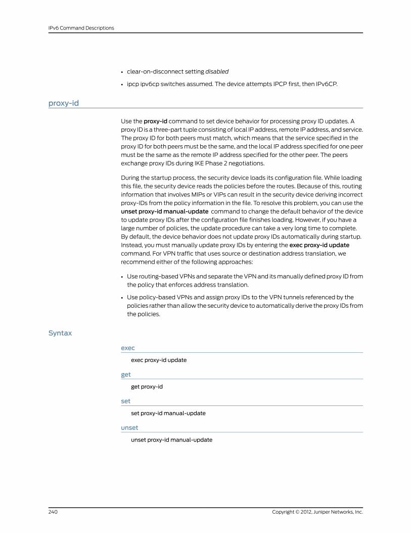
• clear-on-disconnect setting disabled
• ipcp ipv6cp switches assumed. The device attempts IPCP first, then IPv6CP.
proxy-id
Use the proxy-id command to set device behavior for processing proxy ID updates. A
proxy ID is a three-part tuple consisting of local IP address, remote IP address, and service.
The proxy ID for both peers must match, which means that the service specified in the
proxy ID for both peers must be the same, and the local IP address specified for one peer
must be the same as the remote IP address specified for the other peer. The peers
exchange proxy IDs during IKE Phase 2 negotiations.
During the startup process, the security device loads its configuration file. While loading
this file, the security device reads the policies before the routes. Because of this, routing
information that involves MIPs or VIPs can result in the security device deriving incorrect
proxy-IDs from the policy information in the file. To resolve this problem, you can use the
unset proxy-idmanual-update command to change the default behavior of the device
to update proxy IDs after the configuration file finishes loading. However, if you have a
large number of policies, the update procedure can take a very long time to complete.
By default, the device behavior does not update proxy IDs automatically during startup.
Instead, you must manually update proxy IDs by entering the exec proxy-id updatecommand. For VPN traffic that uses source or destination address translation, we
recommend either of the following approaches:
• Use routing-based VPNs and separate the VPN and its manually defined proxy ID from
the policy that enforces address translation.
• Use policy-based VPNs and assign proxy IDs to the VPN tunnels referenced by the
policies rather than allow the security device to automatically derive the proxy IDs from
the policies.
Syntax
exec
exec proxy-id update
get
get proxy-id
set
set proxy-id manual-update
unset
unset proxy-id manual-update
Copyright © 2012, Juniper Networks, Inc.240
IPv6 Command Descriptions

Keywords and Variables
update
exec proxy-id update
Instructs the security device to update all VPN proxy IDs.update
manual-update
set proxy-id manual-updateunset proxy-id manual-update
When set, instructs the security device to update all VPN proxy IDs only inresponse to the exec proxy-id update command. When unset, instructs thesecurity device to update the proxy IDs automatically during route change.
manual-update
Defaults
By default, the security device does not update proxy IDs automatically.
reset
Use the reset command to restart the security device.
Syntax
reset[no-prompt |save-config { no | yes } [ no-prompt ]]
Keywords and Variables
no-prompt
reset no-prompt
Indicates no confirmation.no-prompt
save-config
reset save-config [ no | yes ] [ no-prompt ]
• no—Directs thesecuritydevice tonotsave the current configuration beforeresetting.
• yes—Directs the security device to save the current configuration beforeresetting.
• no-prompt Does not display a confirmation prompt.
save-config
241Copyright © 2012, Juniper Networks, Inc.
Chapter 4: ntp Through RIPng

RIPng Commands
Use the ripng context to begin configuring Routing Information Protocol Next Generation
(RIPng) for a Juniper Networks virtual router.
Initiating the RIPng context
Initiating the ripng context can take up to four steps.
1. Enter the vrouter context by executing the set vrouter command.
set vrouter vrouter
For example:
set vrouter trust-vr
2. Enter the ripng context by executing the set protocol ripng command.
device(trust-vr)-> set protocol ripng
3. Enable RIPng (it is disabled by default).
device(trust-vr/ripng)-> set enable
Table 3 on page 242 shows the commands that are executable in the ripng context.
Table 3: RIPng Commands
RIPng FunctionCommand
Use theadvertise-def-routecommand to advertise the defaultroute (0.0.0.0/0) of the current virtual router the RIPng routingdomain.
Every virtual router may have a default route entry, whichmatches every destination. (Any entry with a more specific prefixoverrides the default route entry.)
Command options: get, set, unset
“advertise-def-route” onpage 244
Use theconfigcommand to view all of the commands executedto configure the RIPng routing instance.
Command option: get
“config” on page 245
Use the debug command to view detailed information aboutthe RIPng instance.
Command option: get
debug
Use the default-metric command to set the RIPng metric forredistributed routes. The default value is 10.
Command options: set, unset
“default-metric” on page 246
Copyright © 2012, Juniper Networks, Inc.242
IPv6 Command Descriptions

Table 3: RIPng Commands (continued)
Use the enable command to enable or disable RIPng in thevirtual router.
Command options: set, unset
“enable” on page 246
Use the flush-timer command to configure the number ofseconds that elapse before ScreenOS automatically removesan invalidated route. The default is 120 seconds.
Command options: set, unset
“flush-timer” on page 246
Displays all routes currently contained in the RIPng garbage list.This list contains routes automatically removed from the routingtable because the device did not obtain the routes in the timeinterval specified by the Invalid Timer setting. When the FlushTimer interval elapses for an entry, the device purges the entryfrom the garbage list.
Command option: get
“garbage-list” on page 247
Use the interface command to display all RIPng interfaces inthe virtual router.
Command options: get
“interface” on page 247
Use the invalid-timer command to configure the number ofseconds that elapse after a neighbor stops advertising a routebefore the route becomes invalid. The default is 180 seconds.
Command options: set, unset
“invalid-timer” on page 247
Use themax-neighbor-count command to set the maximumnumber of RIPng neighbors allowed. The default is 16.
Command options: set, unset
“max-neighbor-count” onpage 248
Use the neighbors command to display the status of RIPngneighbors.
Command options: get
“neighbors” on page 248
Use the redistribute command to import known routes from arouter running a different protocol into the current routinginstance.
You can import the following types of routes:
• Manually created (static) routes
• BGP routes
• OSPF routes
• OSPFv3 routes
• Routes created by an external router, caused by reconnectionof an interface with an IP address
• Routes imported from other virtual routes
Command options: set, unset
“redistribute” on page 249
243Copyright © 2012, Juniper Networks, Inc.
Chapter 4: ntp Through RIPng

Table 3: RIPng Commands (continued)
Use the reject-default-routecommand to cause RIPng to rejecta default route learned from another protocol.
Command options: get, set, unset
“reject-default-route” onpage 250
Use the route-map command to filter routes and offset themetric to a RIPng route matrix.
Command options: get, set, unset
“route-map” on page 250
Use the routes-redistribute command to display redistributedroutes.
Command option: get
“routes-redistribute” onpage 251
Use the rules-redistribute command to display redistributionrules.
Command option: get
“rules-redistribute” on page 251
Use the threshold-update command to set the maximumnumber of routing packets allowed per update interval.
Command options: set, unset
“threshold-update” on page 252
Use the timer command to display RIPng timers.
Command option: get
“timer” on page 252
Use the trusted-neighbors command to set an access list thatdefines RIPng neighbors.
Command options: get, set, unset
“trusted-neighbors” on page 252
Use the update-timer command to set the interval, in seconds,when route updates are issued to RIPng neighbors.
Command options: set, unset
“update-timer” on page 253
Use the update-threshold command to display the number ofrouting packets per update interval.
Command option: get
“update-threshold” on page 253
advertise-def-route
Use the advertise-def-route command to advertise the default route (0::/0) of the
current virtual router.
Every router might have a default route entry, which matches every destination. (Any
entry with a more specific prefix overrides the default route entry.)
Copyright © 2012, Juniper Networks, Inc.244
IPv6 Command Descriptions

Before you can execute the advertise-def-route command, you must initiate the ripngcontext. (See “Initiating the ripng context can take up to four steps.” in “RIPng Commands”
on page 242.)
Syntax
get
get advertise-def-route
set
set advertise-def-route [ always ] {metric number | preserve-metric }
unset
unset advertise-def-route
Keywords and Variables
always
set advertise-def-route always ...
Directs the routing instance to advertise the default route under all conditions,even if there is no default route in the routing table. If you specify always, youmust also specify themetric parameter; you can optionally specify thepreserve-metric parameter. If you do not specify always, you must specifyeither themetric or preserve-metric option.
always
metric
set advertise-def-route alwaysmetric number
Specifies the metric (cost), which indicates the overhead associated with thedefault route. Enter a number between 1 and 15. You must specify thisparameter if you specify the always option.
metric
preserve-metric
set advertise-def-route ... [ preserve-metric ]
Instructs the virtual router to use the original (source) route’s metric foradvertisement when the route is redistributed. When you execute apreserve-metriccommand, in conjunction with a value specified by themetriccommand, the preserve-metric parameter takes precedence over the metricvalue when a route is redistributed.
preserve-metric
config
Use the config command to display all commands executed to configure the RIPng local
virtual router.
Before you can execute the config command, you must initiate the ripng context. (See
“Initiating the ripng context can take up to four steps.” in “RIPng Commands” on page 242.)
Syntax
get config
245Copyright © 2012, Juniper Networks, Inc.
Chapter 4: ntp Through RIPng

Keywords and Variables
None.
debug
Use the debug command to view the RIPng debug information.
Syntax
get debug
Keywords and Variables
None.
default-metric
Use the default-metric command to set the RIPng metric for redistributed routes.
Before you can execute thedefault-metriccommand, you must initiate the ripngcontext.
(See “Initiating the ripng context can take up to four steps.” in “RIPng Commands” on
page 242.)
Syntax
set default-metric number
unsetunset default-metricKeywords and Variables
Variables
set default-metric number
The metric for the routes redistributed into RIPng. This metric value can befrom 1 to 15.
number
enable
Use the enable command to enable or disable RIPng from the current virtual router.
Before you can execute the enable command, you must initiate the ripng context. (See
“Initiating the ripng context can take up to four steps.” in “RIPng Commands” on page 242.)
Syntax
set enable
unsetunset enableKeywords and Variables
None.
flush-timer
Use the flush-timer command to configure the time that elapses before an invalid route
is removed.
Copyright © 2012, Juniper Networks, Inc.246
IPv6 Command Descriptions

Before you can execute the flush-timer command, you must initiate the ripng context.
(See “Initiating the ripng context can take up to four steps.” in “RIPng Commands” on
page 242.)
Syntax
set flush-timer number
unsetunset flush-timerKeywords and Variables
Variables
set flush-timer number
The number of seconds that elapses before an invalid route is removed. Thisvalue must be greater than the current update-timer value. The default valueis 120 seconds.
number
garbage-list
Use the garbage-list command to display all routes currently contained in the RIPng
garbage list. The garbage list contains routes automatically removed from the routing
table because the device did not obtain the routes in the time interval specified by the
Invalid Timer setting. When the Flush Timer interval elapses for an entry, the device
automatically purges the entry from the garbage list.
Before you can execute the garbage-list command, you must initiate the ripng context.
(See “Initiating the ripng context can take up to four steps.” in “RIPng Commands” on
page 242.)
Syntax
get garbage-list
Keywords and Variables
None.
interface
Use the interface command to display all RIPng interfaces on the current virtual router.
Before you can execute the interface command, you must initiate the ripng context. (See
“Initiating the ripng context can take up to four steps.” in “RIPng Commands” on page 242.)
Syntax
get interface
Keywords and Variables
None.
invalid-timer
Use the invalid-timercommand to configure the time that elapses after a neighbor stops
advertising a route before the route becomes invalid.
247Copyright © 2012, Juniper Networks, Inc.
Chapter 4: ntp Through RIPng

Before you can execute the invalid-timer command, you must initiate the ripng context.
(See “Initiating the ripng context can take up to four steps.” in “RIPng Commands” on
page 242.)
Syntax
set invalid-timer number
unsetunset invalid-timerKeywords and Variables
Variables
set invalid-timer number
The number of seconds after a neighbor stops advertising a route that theroute becomes invalid. This value must be greater than the currentupdate-timer value. The default value is 180 seconds.
number
max-neighbor-count
Use themax-neighbor-countcommand to set the maximum number of RIPng neighbors
allowed.
Before you can execute themax-neighbor-count command, you must initiate the ripngcontext. (See “Initiating the ripng context can take up to four steps.” in “RIPng Commands”
on page 242.)
Syntax
set max-neighbor-count numberunset max-neighbor-count
Keywords and Variables
Variables
set max-neighbor-count number
The maximum number of RIPng neighbors allowed. This value can be from 1to the maximum value possible for your security device. The default is 16RIPng neighbors.
number
neighbors
Use the neighbors command to display the status of all RIPng neighbors.
Before you can execute the neighbors command, you must initiate the ripng context.
(See “Initiating the ripng context can take up to four steps.” in “RIPng Commands” on
page 242.)
Syntax
get neighbors
Keywords and Variables
None.
Copyright © 2012, Juniper Networks, Inc.248
IPv6 Command Descriptions

redistribute
Use the redistribute command to import known routes from a router running a different
protocol into the current RIPng routing instance.
You can import the following types of routes:
• Manually created routes (static)
• BGP routes (bgp)
• OSPF routes (ospf)
• OSPF version 3 routes (ospfv3)
• Directly connected interface with an IP address assigned to it (connected)
• Routes that have already been imported (imported)
Before you can execute the redistribute command, you must initiate the ripng context.
(See “Initiating the ripng context can take up to four steps.” in “RIPng Commands” on
page 242.)
Syntax
get
get routes-redistribute
set
set redistribute route-map name_str protocol{ bgp | connected | imported | ospf | ospfv3 | static }
Keywords and Variables
protocol
set redistribute route-map name_str protocol { ... }
Specifies the routing protocol type. The route map can use the protocol typeto the determine whether to permit or deny a route.
• bgp—Specifies that the route map performs an action only on BGP routesin the subnetwork.
• connected—Specifies that the route map performs an action only on routessent from an external router that has at least one interface with an IPaddress assigned to it.
• imported—Specifies that the route map performs an action only onimported routes in the subnetwork.
• ospf—Specifies that the route map performs an action only on OSPF routesin the subnetwork.
• ospfv3—Specifies that the route map performs an action only on OSPFv3routes in the subnetwork.
• static—Specifies that the route map performs an action only on staticroutes in the subnetwork.
protocol
249Copyright © 2012, Juniper Networks, Inc.
Chapter 4: ntp Through RIPng

route-map
set redistribute route-map name_str protocol { ... }
Identifies the route map that specifies the routes to be imported.route-map
Example: The following command redistributes a route that originated from a BGP
routing domain into the current RIPng routing instance:
device(trust-vr/ripng)-> set redistribute route-mapmap1 protocol bgp
reject-default-route
Use the reject-default-route command to cause RIPng to reject default routes learned
from a neighbor in the RIPng domain.
Before you can execute the reject-default-route command, you must initiate the ripngcontext. (See “Initiating the ripng context can take up to four steps.” in “RIPng Commands”
on page 242.)
Syntax
get
get reject-default-route
set
set reject-default-route
Keywords and Variables
None.
route-map
Use the route-map command to filter incoming or outgoing routes.
Before you can execute the route-map command, you must initiate the ripng context.
(See “Initiating the ripng context can take up to four steps.” in “RIPng Commands” on
page 242.)
Syntax
get
get route-map
set
set route-map name_str { in | out }
Copyright © 2012, Juniper Networks, Inc.250
IPv6 Command Descriptions

Keywords and Variables
Variables
set route-map name_str
The name of the route map to filter routes.name_str
in
set route-map name_str in
Specifies the route map is applied to routes to be learned by RIPng.in
out
set route-map name_str out
Specifies the route map is applied to routes to be advertised by RIPng.out
Example:The following command applies the route map map1 to routes to be advertised
by RIPng:
device(trust-vr/ripng)-> set route-mapmap1 out
routes-redistribute
Use the routes-redistribute command to display details about routes imported from
other protocols into RIPng.
Before you can execute the routes-redistribute command, you must initiate the ripngcontext. (See “Initiating the ripng context can take up to four steps.” in “RIPng Commands”
on page 242.)
Syntax
get routes-redistribute
Keywords and Variables
None.
rules-redistribute
Use the rules-redistribute command to display conditions set for routes imported from
other protocols into RIPng.
Before you can execute the rules-redistribute command, you must initiate the ripngcontext. (See “Initiating the ripng context can take up to four steps.” in “RIPng Commands”
on page 242.)
Syntax
get rules-redistribute
251Copyright © 2012, Juniper Networks, Inc.
Chapter 4: ntp Through RIPng

Keywords and Variables
None.
threshold-update
Use the threshold-update command to set the maximum number of routing packets
received and processed per update interval, per neighbor.
Before you can execute the threshold-update command, you must initiate the ripngcontext. (See “Initiating the ripng context can take up to four steps.” in “RIPng Commands”
on page 242.)
Syntax
set threshold-update number
unsetunset threshold-updateKeywords and Variables
Variables
set threshold-update number
The maximum number of routing packets allowed per update interval. Thisvalue must be greater than zero.
number
timer
Use the timer command to display information about various RIPng timers.
Before you can execute the timer command, you must initiate the ripng context. (See
“Initiating the ripng context can take up to four steps.” in “RIPng Commands” on page 242.)
Syntax
get timer
Keywords and Variables
None.
trusted-neighbors
Use the trusted-neighborscommand to specify an access list that defines allowed RIPng
neighbors.
Before you can execute the trusted-neighbors command, you must initiate the ripngcontext. (See “Initiating the ripng context can take up to four steps.” in “RIPng Commands”
on page 242.)
Syntax
get
get trusted-neighbors
Copyright © 2012, Juniper Networks, Inc.252
IPv6 Command Descriptions

set
set trusted-neighbors id_num
Keywords and Variables
Variables
set trusted-neighbors id_num
The number of the access list that defines the allowed RIPng neighbors.id_num
update-timer
Use the update-timer command to set the interval that RIPng sends route updates to
neighbors.
Before you can execute the update-timer command, you must initiate the ripng context.
(See “Initiating the ripng context can take up to four steps.” in “RIPng Commands” on
page 242.)
Syntax
set update-timer number
Keywords and Variables
Variables
set update-timer number
The interval, in seconds, that RIPng sends route updates to neighbors. Thisvalue must be at least one, and no greater than the current invalid-timervalue. The default is 30 seconds.
number
update-threshold
Use theupdate-thresholdcommand to display the number of routing packets per update
interval.
Before you can execute the update-threshold command, you must initiate the ripngcontext. (See “Initiating the ripng context can take up to four steps.” in “RIPng Commands”
on page 242.)
Syntax
get update-threshold
Keywords and Variables
None.
253Copyright © 2012, Juniper Networks, Inc.
Chapter 4: ntp Through RIPng

Copyright © 2012, Juniper Networks, Inc.254
IPv6 Command Descriptions

CHAPTER 5
rm Through zone
This section lists and describes the ScreenOS command line interface (CLI) commands
rm through zone.
NOTE: Certain commands and features are platform-dependent andmightbe unavailable on your Juniper Networks security product platform. Checkyour product datasheet for feature availability.
Click on a command for details:
• rm on page 256
• route on page 257
• sa on page 259
• sa-filter on page 261
• sa-statistics on page 261
• sat on page 262
• save on page 263
• scheduler on page 267
• scp on page 268
• service on page 269
• session on page 272
• session-cache on page 277
• snmp on page 278
• snmpv3 on page 281
• socket on page 287
• syslog on page 287
• system on page 290
• tech-support on page 290
• tftp on page 290
• timer on page 291
255Copyright © 2012, Juniper Networks, Inc.

• trace-route on page 292
• traffic-shaping on page 293
• url on page 295
• user on page 298
• user-group on page 302
• vip on page 304
• vlan on page 305
• vpn on page 308
• vpn-group on page 316
• vpnmonitor on page 317
• vrouter on page 318
• vsys on page 330
• vsys-profile on page 334
• webauth on page 339
• webtrends on page 340
• xauth on page 341
• xlate on page 343
• zone on page 343
rm
Use the rm commands to view the resource manager settings. These settings include
client heatbeat and pinhole age.
Syntax
get rm{group { id_number | active } |resource { id_number | active } |
Copyright © 2012, Juniper Networks, Inc.256
IPv6 Command Descriptions

settings}
Keywords and Variables
Displays resource manager details. The arguments for this keyword are asfollows:
• group { id_number | active }—Displays information about a particulargroup. You can limit the output by appending a specific group ID numberor expand the output by appending active include all active groups in theoutput.
• resource { id_number | active }—Displays information about a particularresource. You can limit the output by appending a specific resource IDnumber or expand the output by appending active to include all activegroups in the output.
• settings—Displays the client heatbeat (timeout and count) and pinholeage (in seconds).
rm
route
Use the route commands to display entries in the static route table.
The get route command displays:
• The IP address, netmask, interface, gateway, protocol, preference, metric, and owner
vsys
• The protocol value can be any of the following:
• C (Connected)
• S (Static)
• A (Auto Exported)
• I (Imported; that is, route imported from another virtual router)
• iB (internal BGP)
• eB (external BGP)
• O (OSPF)
• E1 (OSPF external type 1)
• E2 (OSPF external type 2)
Use the get route command to see if the security device has a route to the IP address on
the correct interface.
Syntax
get route [ v4 | v6 ][
257Copyright © 2012, Juniper Networks, Inc.
Chapter 5: rm Through zone
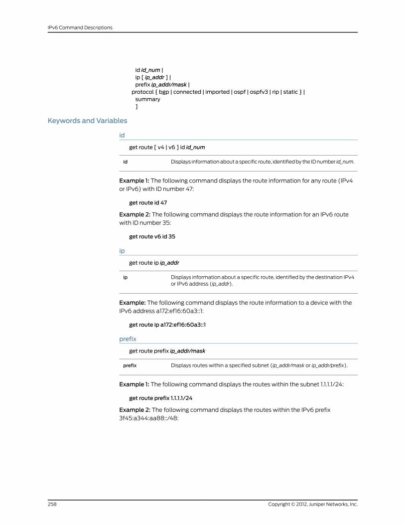
id id_num |ip [ ip_addr ] |prefix ip_addr/mask |protocol { bgp | connected | imported | ospf | ospfv3 | rip | static } |summary]
Keywords and Variables
id
get route [ v4 | v6 ] id id_num
Displays information about a specific route, identified by the ID number id_num.id
Example 1: The following command displays the route information for any route (IPv4
or IPv6) with ID number 47:
get route id 47
Example 2: The following command displays the route information for an IPv6 route
with ID number 35:
get route v6 id 35
ip
get route ip ip_addr
Displays information about a specific route, identified by the destination IPv4or IPv6 address (ip_addr).
ip
Example: The following command displays the route information to a device with the
IPv6 address a172:ef16:60a3::1:
get route ip a172:ef16:60a3::1
prefix
get route prefix ip_addr/mask
Displays routes within a specified subnet (ip_addr/mask or ip_addr/prefix).prefix
Example 1: The following command displays the routes within the subnet 1.1.1.1/24:
get route prefix 1.1.1.1/24
Example 2: The following command displays the routes within the IPv6 prefix
3f45:a344:aa88::/48:
Copyright © 2012, Juniper Networks, Inc.258
IPv6 Command Descriptions

get route prefix 3f45:a344:aa88::/48
protocol
get route protocol { bgp | connected | discovered | imported | ospf | ospfv3 | prefix | rip |ripng | static }
Specifies the routing protocol and directs the security device to display theroutes derived from that protocol.
• bgp—Directs the device to display BGP routes.
• connected—Directs the device to display only routes sent from an externalrouter that has at least one interface with an IP address assigned to it.
• discovered—Directs the device to display only routes discovered from thesubnetwork.
• imported—Directs the device to display imported routes.
• ospf—Directs the device to display only OSPF routes.
• ospfv3—Directs the device to display only OSPFv3 routes.
• prefix—Directs the device to display routes that have assigned prefixes.
• rip—Directs the device to display RIP routes (for IPv4 only).
• ripng—Directs the device to display RIPng routes (for IPv6 only).
• static—Directs the device to display only static routes.
protocol
source
get route source { id id_num | in-interface { ... }| ip ip_addr | prefix ip_addr/pref_len }
Displays summary information for source routes.
• id id_num—Displays a source route, identified by id_num.
• in-interface—Displays SIBR routes. You can choose to identify a particularroute by including an ID number, an IPv4 address, or an IPv6 prefix.
• ip ip_addr—Displays a source route, identified by an IPv4 or IPv6 address,ip_addr.
• prefix ip_addr/pref_len—Displays all source routes within the prefix specifiedby ip_addr/pref_len.
source
summary
get route summary
Displays summary information, including number of routes, for each protocol.summary
Defaults
The get route command displays all entries in the route table unless a particular target
IP address is specified.
sa
Use the sa commands to display active or inactive security associations (SAs) or to clear
a specified SA.
259Copyright © 2012, Juniper Networks, Inc.
Chapter 5: rm Through zone

A security association (SA) is a unidirectional agreement between VPN participants
regarding the methods and parameters to use while securing a communication channel.
Full bidirectional communication requires at least two SAs, one for each direction.
An SA groups together the following components for securing communications:
• Security algorithms and keys
• Protocol mode (transport or tunnel)
• Key management method (Manual Key or AutoKey IKE)
• SA lifetime
For outbound VPN traffic, a security policy invokes the SA associated with the VPN tunnel.
For inbound traffic, the security device looks up the SA by using the following triplet:
destination IP, security protocol (AH or ESP), and security parameter index (SPI) value,
which are sent to the peer in the first message of a Phase 1 IKE exchange.
Syntax
clear
clear [ cluster ] sa id_num
get
get sa[id id_num |[ active | inactive ] stat]
Keywords and Variables
Variables
clear [ cluster ] sa id_num
Specifies the SA ID number.id_num
cluster
clear cluster sa id_num
Propagates the clear operation to all other devices in an NSRP cluster.cluster
id
get sa id id_num
Displays a specific IPsec Security Association (SA) entry with the ID number.id
Copyright © 2012, Juniper Networks, Inc.260
IPv6 Command Descriptions

stat
get sa [ ... ] stat
Shows the SA statistics for the device.
Displays these statistics for all incoming or outgoing SA pairs:
• Fragment—The total number of fragmented incoming and outgoingpackets.
• Auth-fail—The total number of packets for which authentication has failed.
• Other—The total number of miscellaneous internal error conditions otherthan those listed in the auth-fail category.
• Total Bytes—The amount of active incoming and outgoing traffic
stat
sa-filter
Use the sa-filter command to debug messages for each Security Association (SA) filter.
Syntax
get
get sa-filter
set
set sa-filter ip_addr
Keywords and Variables
Variables
set sa-filter ip_addrunset sa-filter ip_addr
Specifies an Internet Protocol address (IP Address) for the SA to filter.ip_addr
all
unset sa-filter all
Unsets all SA filters.all
sa-statistics
Use the sa-statistics command to clear all statistical information (such as the number
of fragmentations and total bytes through the tunnel) in a security association (SA) for
an AutoKey IKE VPN tunnel.
Syntax
clear [ cluster ] sa-statistics [ id id_num ]
261Copyright © 2012, Juniper Networks, Inc.
Chapter 5: rm Through zone

Keywords and Variables
cluster
clear cluster sa-statistics id id_num
If the security device is in a high availability (HA) configuration, propagatestheclearoperation to all other devices in the NetScreen Redundancy Protocol(NSRP) cluster.
cluster
id
clear [ cluster ] sa-statistics id id_num
Clears the SA statistics for a particular SA.id id_num
Example: The following command clears the SA statistics for SA 2:
clear sa-statistics id 2
sat
Use the sat commands to display the counter information of ASICs used in high-end
platforms. These commands provide details about ASIC counters such as Q pointers,
buffers, and number of packets forwarded to the CPU.
Syntax
get
get sat number{counters |demux-counter |frq1 |session |x-context |
}
Keywords and Variables
Variable Parameter
get sat number
Specifies the ASIC identified by the Saturn ID.number
counters
get sat number counter
Displays information about the read-write pointers and the full counters ofeach queue in an ASIC.
counter
Copyright © 2012, Juniper Networks, Inc.262
IPv6 Command Descriptions

demux-counter
get sat number demux-counter
Specifies the number of unique demux packets forwarded to the CPU.demux-counter
frq1
get sat number frq1
Displays the status of free buffer queue. Use the command to check forpresence of leak in the buffer queue.
frq1
session
get sat number session
Displays the total number of allocated hardware sessions.session
x-context
get sat number x-context
Displays the records of various memory tables, table addresses, and resetcounters of an ASIC.
x-context
save
Use the save commands to save the security device configuration settings either to flash
memory, a flash memory card, or a Trivial File Transfer Protocol (TFTP) server.
Syntax
save
save
save config
save config[all-virtual-system |to{flash |slot1 filename |tftp ip_addr filename}[ merge ] |from
{flash |slot1 filename |
263Copyright © 2012, Juniper Networks, Inc.
Chapter 5: rm Through zone

tftp ip_addr filename[merge |to{flash [ from interface ] |last-known-good |slot1 filename |tftp ip_addr filename [ from interface ]}[ from interface ]
}]
save file
save file filenamefrom{slot1 filename |tftp ip_addr filename [ from interface ] |usb filename
}to{slot1 filename |tftp ip_addr filename [ from interface ] |
usb filename}
save image-key
save image-key tftp ip_addr filename from interface
save software
save software from{flash |slot1 filename |tftp ip_addr filename}to{flash |slot1 filename |tftp ip_addr filename}[ from interface ]
Keywords and Variables
all-virtual-system
save config all-virtual-system
Saves all virtual system configurations.all-virtual-system
Copyright © 2012, Juniper Networks, Inc.264
IPv6 Command Descriptions

flash
save config from { ... } to flash [ from interface ]save config from flash to { ... } [ from interface ]save software from flash to { ... } [ from interface ]save software from { ... } flash to [ from interface ]
Saves from (or to) flash memory. The from interface option specifies thesource interface if you specify TFTP.
flash
Example 1: The following command saves the current configuration from flash memory
to a file (output.txt) on a TFTP server (172.16.10.10):
save config from flash to tftp 172.16.10.10 output.txt
Example 2: The following command saves the current configuration from flash memory
to a file (output.txt) on an IPv6 TFTP server (2eee::1):
save config from flash to tftp 2eee::1 output.txt
from { ... } to
save config from { ... } to { ... }save file filename from { ... } to { ... }save software from { ... } to { ... }
Saves from the specified source.from
Saves to the specified destination.to
Example 1: The following command saves the current configuration from flash memory
to a file (output.txt) on a TFTP server (IP address 172.16.10.10):
save config from flash to tftp 172.16.10.10 output.txt
Example 2: The following command saves the current configuration from flash memory
to a file (output.txt) on an IPV6 TFTP server (IP address 2eee::1):
save config from flash to tftp 2eee::1 output.txt
last-known-good
save config to last-known-good
Saves the current configuration to flash memory as the LKG(last-known-good) configuration. The security device can revert to this LKGfile by doing a configuration rollback. The security device automatically namesthe LKG file $LKG$.cfg. You cannot rename the LKG file or give it a differentname upon saving it.
last-known-good
265Copyright © 2012, Juniper Networks, Inc.
Chapter 5: rm Through zone

merge
save config from { ... } merge [ from interface ]
Merges the saved configuration with the current configuration. The frominterface option specifies the source interface.
merge
Example:The following command merges the current configuration with the configuration
in a file (input.txt) on a TFTP server (IP address 172.16.10.10):
save config from tftp 172.16.10.10 input.txt merge
Example 2: The following command merges the current configuration with the
configuration in a file (input.txt) on an IPv6 TFTP server (IP address 2eee::1):
save config from tftp 2eee::1 input.txt merge
slot1
save config from { ... } to slot1 [ ... ]save config from slot1 to { ... }save file filename from { ... } to slot [ ... ]save file filename slot1 to { ... }save software from slot1 to { ... }save software from { ... } to slot1 [ ... ]
Saves from (or to) a file in the memory card slot.slot1
Example:The following commands saves the current configuration from a file (input.txt)
in the slot1 memory card to flash memory:
save config from slot1 input.txt to flash
tftp
save config from tftp filename to { ... } [ from interface ]save file filename from tftp ip_addr filename [ from interface ] to { ... }save image-key tftp ip_addr filename from interfacesave software from tftp filename to { ... } [ from interface ]
Saves from (or to) a file on a TFTP server.tftp
Example 1: The following command loads an authentication key on a FIPS-compliant
security device from a file named nskey.cer on a TFTP server at 10.10.1.2:
save image-key tftp 10.10.1.2 nskey.cer
Example 2: The following command loads an authentication key on a FIPS-compliant
security device from a file named nskey.cer on an IPv6 TFTP server at 2eee::1:
Copyright © 2012, Juniper Networks, Inc.266
IPv6 Command Descriptions

save image-key tftp 2eee::1 nskey.cer
usb
save file filename usb filename to { ... }
Saves from (or to) a file on a USB key using the USB host module.usb
scheduler
Use the scheduler commands to create or modify a schedule, or to display the settings
in a schedule.
A schedule is a configurable object that you can use to define when policies are in effect.
security devices use schedules to enforce the policies at specified times or intervals.
Through the application of schedules, you can control network traffic flow and enforce
network security.
Syntax
get
get scheduler [ name name_str | once | recurrent ]
set
set scheduler name_str[once start date time stop date time [ comment string ] |recurrent{ monday | tuesday | wednesday | thursday | friday | saturday | sundaystart time stop time
}[ start time stop time ][ comment string ]
]
Keywords and Variables
name
get scheduler name name_str
Defines a name for the schedule.name name_str
once
get scheduler onceset scheduler name_str once start date time stop date time [ ... ]
Apply the schedule once, starting on the day, month, year, hour, and minutedefined, and stopping on the month, day, year, hour, and minute defined.
once
267Copyright © 2012, Juniper Networks, Inc.
Chapter 5: rm Through zone

recurrent
get scheduler recurrentset scheduler name_str recurrent { ... } [ ... ]
Directs the security device to repeat the schedule according to the definedday of the week, hour, and minutes.
• monday —Repeat every Monday.
• tuesday —Repeat every Tuesday.
• wednesday —Repeat every Wednesday.
• thursday —Repeat every Thursday.
• friday —Repeat every Friday.
• saturday —Repeat every Saturday.
• sunday —Repeat every Sunday.
• start—Defines when to start the schedule.
• stop—Defines when to stop the schedule.
• comment—Defines a descriptive character string.
recurrent
start | stop
set scheduler name_str once start date time stop date time [ ... ]set scheduler name_str recurrent { ... } start time stop time [ ... ]
Defines the day, month, and year (date) in USA format (mm/dd/yyyy).start | stop
Defines the hour and minutes (time) in the 24-hour clock format (hh:mm).
Example 1:The following command creates a schedule definition named “ mytime” which
starts on 1/10/2003 at 11:00 AM and ends on 2/12/2003 at 7:00 PM:
set scheduler mytime once start 1/10/2003 11:00 stop 2/12/2003 19:00
Example 2: The following command creates a schedule definition named “ weekend”
which starts at 8:00 AM and ends at 5:00 PM and repeats every Saturday and Sunday:
set scheduler weekend recurrent saturday start 8:00 stop 17:00set scheduler weekend recurrent sunday start 8:00 stop 17:00
scp
Use the scp commands to configure the Secure Copy (SCP) client/server on security
devices. SCP provides a way of transferring files to or from the security device using the
SSH protocol.
NOTE: It is possible to initiate file transfer from an external host, not fromthe security device itself.
Copyright © 2012, Juniper Networks, Inc.268
IPv6 Command Descriptions

Syntax
get
get scp
set
set scp enable
Keywords and Variables
enable
set scp enableunset scp enable
Enables the Secure Copy (SCP) task. When SCP is enabled, the SSH task isactivated if it is not already active.
enable
service
Use the service commands to create custom service definitions, modify existing service
definitions, or display the current entries in the service definition list.
Use service definitions in policies to specify how the security device provides a service
during a secure session. For example, a custom service definition might permit sessions
using TCP protocol to exchange traffic between specified source and destination ports.
Any policy that uses this definition conforms to these specifications.
Syntax
get
get service[name_str |group [ name_str ] |pre-defined |timeout { other | tcp | udp } [ port number1 [ number2 ] ] |user]
set
set service name_str[+{icmp type number code number |ptcl_num | tcp | udp{ src-port number-number dst-port number-number }
} |protocol{
269Copyright © 2012, Juniper Networks, Inc.
Chapter 5: rm Through zone

ptcl_num | tcp | udp[ src-port number-number ][ dst-port number-number [ timeout { number | never } ] ] |
icmp type number code number |} |
timeout { number | never } | session-cache ]
Keywords and Variables
Variables
get service name_strset service name_str [ ... ]unset service name_str
Defines a name for the service.name_str
+
set service name_str + { ... }
Appends a service entry to the custom services list.+
pre-defined
get service pre-defined
Displays all the predefined services.pre-defined
protocol
set service name_str protocol { ... } [ ... ]
Defines the service by IP protocol.
Defines a protocol for the specified service.
• ptcl_num—Specifies the protocol by protocol number.
• icmp—Specifies an ICMP-based service.
• type—Identifies the ICMP message type, for example, DestinationUnreachable.
• code—Identifies a specific message from an ICMP message type group.For example, from the Destination Unreachable type group, there arevarious more specific messages identified by code such as NetUnreachable, Host Unreachable, Protocol Unreachable, and so on.
• tcp—Specifies a TCP-based service.
• udp—Specifies a UDP-based service.
protocol
Example: The following command sets a service named ipsec that uses protocol 50:
set service ipsec protocol 50
session cache
set service name_str session-cache
Copyright © 2012, Juniper Networks, Inc.270
IPv6 Command Descriptions

unset service name_str session-cache
Enables or disables the session cache for a certain service. By default, thesession cache is disabled.
session-cache
Example: The following command enables session cache for the AOL service:
set service AOL session-cache
src-port | dst-port
set service name_str protocol { ... }[ src-port number-number ] [ dst-port number-number ]
Defines a range of source port numbers valid for the service and protocol.src-port
Defines a range of destination port numbers valid for the service and protocol.dst-port
Example: The following command sets a service named test1 that uses destination tcp
port 1001:
set service test1 protocol tcp src-port 0-65535 dst-port 1001-1001
timeout
get service timeout { other | tcp | udp } [ port number1 [ number2 ] ]set service name_str timeout { number | never }unset service name_str timeout
Sets or displays the timeout value for session sessions created on a port forTCP, UDP, or other protocols. You can specify session timeout value (number)in minutes or as never.
timeout
Example1: The following command sets telnet service to timeout after 10 minutes:
set service telnet timeout 10
Example2: The following command displays timeouts for UDP from port 1720 to 1800:
get service timeout udp port 1720 1800
user
get service user
Displays all user-defined services.user
Defaults
The default timeout for TCP connections is 30 minutes.
The default timeout for UDP connections is 1 minute.
271Copyright © 2012, Juniper Networks, Inc.
Chapter 5: rm Through zone

NOTE: The timeout value for TCPconnections andUDPconnections is 2160minutes.
Using the get service command without any arguments displays all predefined,
user-defined, and service-group information in the service book.
session
Use the session commands to clear or display entries in the session table of the security
device.
The session table contains information about individual sessions between hosts that
communicate through the security device. Because each session entry uniquely identifies
two communicating hosts, it contains a unique combination of the following criteria:
• Individual IP address for the source host (no subnets with multiple addresses)
• Individual IP address for the destination host (no subnets with multiple addresses)
• Individual port number for the source host (not a range of ports)
• Individual port number for the destination host (not a range of ports)
Every time the security device initiates a new session, it creates a session entry and uses
the information in the entry while processing subsequent traffic between the hosts.
The kind of session information listed by the get session command depends upon the
security device platform. (For example, on any platform with a management module in
slot 1, the get session command lists currently active sessions on that module.) Such
sessions include management, log, and other administrative traffic. On any security device
with one or more Secure Port Modules (SPMs), the get session command lists sessions
that are active on the ASIC for each module. If a session crosses two ASICs, it counts as
two sessions, one for each ASIC.
Syntax
clear
clear [ cluster ] session[all |id id_num |[ src-ip ip_addr [ netmaskmask ] ][ dst-ip ip_addr [ netmaskmask ] ][ src-macmac_addr ] [ dst-macmac_addr ][ protocol ptcl_num [ ptcl_num ] ][ src-port port_num [ port_num ] ][ dst-port port_num [ port_num ] ][ vsd-id id_num ] [ vsys-name name_str ] | [ vsys-id id_num ]
]
Copyright © 2012, Juniper Networks, Inc.272
IPv6 Command Descriptions

get
get session[id id_num |info |fragment |[ tunnel ][ src-ip ip_addr [ netmaskmask ] ][ dst-ip ip_addr [ netmaskmask ] ][ src-macmac_addr ] [ dst-macmac_addr ][ protocol ptcl_num [ ptcl_num ] ][ src-port port_num [ port_num ] ][ dst-port port_num [ port_num ] ]
sm-slot slot-idsm-cpu cpu-num
]
Keywords and Variables
all
clear [ cluster ] session all
Specifies all sessions.all
cluster
clear cluster session [ ... ]
Propagates the clear operation to all other devices in an NSRP cluster.cluster
id
clear [ cluster ] session id id_numget session id id_num
Identifies a specific session with session identification number id_num.id id_num
Example: The following command displays the session table entry for the session with
ID 5116:
get session id 5116
info
get session info
Displays the summary of all sessions.info
src-ip | dst-ip
clear [ cluster ] session [ src-ip ip_addr [ netmaskmask ] ][ dst-ip ip_addr [ netmaskmask ] ] [ ... ]
273Copyright © 2012, Juniper Networks, Inc.
Chapter 5: rm Through zone

get session [ ... ] [ src-ip ip_addr [ netmaskmask ] ][ dst-ip ip_addr [ netmaskmask ] ][ ... ]
Identifies all sessions initiated by packets containing source IP address ip_addr.For example, ip_addr could be the source IP address in the first TCP SYNpacket. For clear commands, IPv4 or IPv6 addresses are acceptable.
src-ip ip_addr
Identifies all sessions initiated by packets containing destination IP addressip_addr. For clear commands, IPv4 or IPv6 addresses are acceptable.
dst-ip ip_addr
Example 1: The following command displays all the entries in the session table for a
specific source IP address:
get session src-ip 172.16.10.92
Example2:The following command clears all the entries in the session table for a specific
source IPv6 address:
clear session src-ip 2eee::1
src-mac | dst-mac
clear [ cluster ] session [ ... ] [ dst-ip ip_addr [ netmaskmask ] ][ src-macmac_addr ] [ dst-macmac_addr ]
get session [ ... ] [ src-ip ip_addr [ netmaskmask ] ][ dst-ip ip_addr [ netmaskmask ] ]
Identifies all sessions initiated by packets containing source MAC addressmac_addr.
src-mac
Identifies all sessions initiated by packets containing destination MAC addressmac_addr.
dst-mac
protocol
clear [ cluster ] session [ ... ] protocol ptcl_num [ ptcl_num ] [ ... ]get session [ ... ] protocol ptcl_num [ ptcl_num ] [ ... ]
Identifies all sessions that use protocol ptcl_num.
You can also specify any protocol within a range (ptcl_num ptcl_num).
protocol
src-port | dst-port
clear [ cluster ] session [ ... ] [ src-port port_num [ port_num ] ][ dst-port port_num [ port_num ] ] [ ... ]
get session [ ... ] [ src-port port_num [ port_num ] ][ dst-port port_num [ port_num ] ]
Identifies all sessions initiated by packets that contain the Layer 4 source portport_num in the Layer 4 protocol header.
You can also specify any Layer 4 destination port within a range (port_numport_num).
src-port
Copyright © 2012, Juniper Networks, Inc.274
IPv6 Command Descriptions

Identifies all sessions initiated by packets that contain the Layer 4 destinationport port_num in the Layer 4 protocol header.
You can also specify any Layer 4 destination port within a range (port_numport_num).
dst-port
Example:The following command displays all the entries in the session table for protocol
5 and for source ports 2 through 5:
get session protocol 5 src-port 2 5
tunnel
get session tunnel [ ... ]
Directs the security device to display tunnel sessions.tunnel
sm-slot
get session sm-slot slot-id
Displays the sessions using the specified slot ID.sm-slot
Slot ID of the security device. The slot-id value ranges from 1 to 3.slot-id
sm-cpu
get session sm-cpu cpu-num
Displays the sessions using the specified CPU.sm-cpu
The CPU whose session details you need to display. The value can be 0 or 1.cpu-num
vsd-id
clear [ cluster ] session [ ... ] vsd-id id_numget session [ ... ] vsd-id id_num
Identifies all sessions that belong the VSD group id_num.vsd-id id_num
Example: The following command clears all sessions belonging to VSD group 2001 and
initiated from the host at IP address 172.16.10.12:
clear session src-ip 172.16.10.12 vsd-id 2001
vsys-name
clear [ cluster ] session [ ... ] vsys-name name_str
Identifies all sessions that belong to the specified virtual systems (vsys).vsys-name
275Copyright © 2012, Juniper Networks, Inc.
Chapter 5: rm Through zone

vsys-id
clear [ cluster ] session [ ... ] vsys-id id_num
Identifies all sessions of a vsys with the vsys identification number id_num.vsys-id
Copyright © 2012, Juniper Networks, Inc.276
IPv6 Command Descriptions

session-cache
Use the session-cache commands to enable the security device to cache the software
and hardware sessions of an HTTP session.
Syntax
clear
clear session-cache { data | statistics }
get
get session-cache [ all | service service-name ]
set
set session-cache enable
Keywords and Variables
all
get session-cache [ all ]
Displays all the session-cache entries in the virtual system (vsys).all
data
clear session-cache { data | statistics }
Clears data or statistical information from the session-cache table.data
enable
set session-cache enableunset session-cache enable
Enables or disables the session cache. By default, the session cacheis disabled.
enable
number
set session-cache count numberunset session-cache count
Changes the size of the session cache. The range is 1 to 64.number
Example 1: The following command changes the session cache size.
set session-cache count 18
277Copyright © 2012, Juniper Networks, Inc.
Chapter 5: rm Through zone

The cache entry count indicates the current cache size and is determined by the
session-cache count and the weight of the session cache count, which is 1024.
Example 2:When you set the session cache count to 18, the cache entry count changes
to 18432 (18*1024). Thegetsession-cachecommand displays the session cache details.
get session-cacheSession cache is disabled in the current VSYSSession cache is opened on service:NONECache entry size: 384 bytes, cache entry count 18432, used in the current vsys 0, freecache entry 18432Total sessions created by cache: 0Average cache hit: 0%Average cachemiss: 0%Average cachemiss when table full: 0%
NOTE: Theunusedmemory isnot freedwhenyouset thesessioncachecountto a smaller value. You have to reset the security device to free the unusedmemory.
service-name
get session-cache [ service service-name ]
Displays the session cache entries for a specified service inthe virtual system (vsys).
service-name
Example:The following command displays the session cache entries for a service named
AOL.
get session-cache service AOL
NOTE: All the session-cache commands are configured in the vsys exceptfor session-cachecount, which is configured in the root vsys and later sharedby all systems.
snmp
Use the snmp commands to configure the security device for Simple Network
Management Protocol (SNMP), to gather statistical information from the security device,
and to receive notifications when significant events occur.
Syntax
get
get snmp [ auth-trap | community name_str | settings ]
set
set snmp
Copyright © 2012, Juniper Networks, Inc.278
IPv6 Command Descriptions

{auth-trap enable |community name_str{ read-only | read-write }[trap-off |trap-on [ traffic ] |version { any | v1 | v2c }] |
contact name_str |host comm_name ip_addr[/mask ][src-interface interface |trap { v1 | v2c }] |
location string |name name_str |port { listen [ port_num ] | trap [ port_num ] }}
Keywords and Variables
auth-trap enable
get snmp auth-trapset snmp auth-trap enableunset snmp auth-trap enable
Enables Simple Network Management Protocol (SNMP) authentication traps.auth-trap enable
community
get snmp community name_strset snmp community name_str { ... }unset snmp community name_str
Defines the name for the SNMP community. It supports maximum 3communities in all products.
• read-only—Defines the permission for the community as “ read-only.”
• read-write—Defines the permission for the community as “ read-write.”
• trap-off—Disables SNMP traps for the community.
• trap-on—Enables SNMP traps for the community. The traffic switchincludes traffic alarms as SNMP traps.
community
Examples: The following command configures a community named “ public” .
• Allows hosts to read MIB data from the SNMP agent
• Enables SNMP traps for the community
set snmp community public read-only trap-on
The following command configures an SNMP host with IP address 10.20.25.30 for the
community named “ public” :
279Copyright © 2012, Juniper Networks, Inc.
Chapter 5: rm Through zone

set snmp host public 10.20.25.30
contact
set snmp contact name_strunset snmp contact
Defines the system contact.contact
host
set snmp host comm_name ip_addr [/mask ] [ ... ]unset snmp host comm_name ip_addr [ ... ]
Defines the community name string and the IP address of the SNMPmanagement host. The mask value defines an SNMP community memberas a subnet.
Note:When you define an SNMP community member as a subnet, thatmember can poll the security device but it cannot receive SNMP traps. Toreceive SNMP traps, the community member must be a single host.
host
Example: The following commands configure a community named “ netscreen.”
• Specifies read and write permission
• Allows the security device to send traps to all hosts in the community
• Assigns the community to an SNMP host with IP address 10.40.40.15
set snmp community netscreen read-write trap-onset snmp host netscreen 10.40.40.15
Example: The following command defines the subnet 10.5.1.0/24 as a member of the
SNMP community named olympia:
set snmp host olympia 10.5.1.0/24
location
set snmp location stringunset snmp location
Defines the physical location of the system.location
name
set snmp name name_strunset snmp name
Defines the name of the system.name
port
set snmp port { ... }
Copyright © 2012, Juniper Networks, Inc.280
IPv6 Command Descriptions

unset snmp port { ... }
Specifies the SNMP listen and trap port ( listen | trap ).port
settings
get snmp settings
Displays the name of the contact person, and the name and physical locationof the security device.
settings
src-interface
set snmp host comm_name ip_addr[/mask ] src-interface interfaceunset snmp host comm_name ip_addr[/mask ] src-interface
Specifies the source interface.src-interface
trap
set snmp host comm_name ip_addr[/mask ] trap v1 | v2c
If an SNMP community supports both SNMP versions (SNMPv1 (v1) andSNMPv2c (v2c), you must specify a trap version for each community member.
trap
version
set snmp community { ... } version { any | v1 | v2c }
When you create an SNMP community, you can specify whether thecommunity supports SNMPv1 (v1), SNMPv2c (v2c), or both SNMP versions,as required by the SNMP management stations. For backward compatibilitywith earlier ScreenOS releases that only support SNMPv1, security devicessupport SNMPv1 by default.
version
snmpv3
Use the snmpv3 commands to configure the security device for Simple Network
Management Protocol version 3 (SNMPv3), to gather statistical information from the
security device, and to receive notification about significant system events.
• Syntax on page 281
• Keywords and Variables on page 283
Syntax
get
get snmpv3 { access | community | filter | group-mapping | local-engine | target-param |target | user | view }
281Copyright © 2012, Juniper Networks, Inc.
Chapter 5: rm Through zone

set
set snmpv3{access group group-name{sec-model { any | usm | v1 | v2c }sec-level { auth | priv | none }read view-namewrite view-namenotify view-name} |
community community-name tag tag-value |filter name filter-name{oid oidmaskmasktype { include | exclude }} |
filter filter-name{sec-model { v1 | v2c | usm }sec-level { auth | priv | none }[ user username ] |[ community community-name ]} |
group-mapping sec-model { v1 | v2c | usm }{[ user username ] |community community-name ]} |group group-name |
local-engine id engine-id |target-param param-name{filter filter-namesec-model { v1 | v2c | usm }sec-level { auth | priv | none }[ user username ] |[ community community-name ]} |
target target-name{address { ipaddr/mask [ port portnum param-name ] }tag tag-value} |
user username{auth {md5 | sha | none }auth-pass passwordpriv { none | des }priv-pass password} |
view name view-name{
Copyright © 2012, Juniper Networks, Inc.282
IPv6 Command Descriptions

oid oidmaskmasktype { include | exclude }}
}
Keywords and Variables
access group
get snmpv3 accessset snmpv3 access group { ... }unset snmpv3 access group { ... }
Configure an entry in the View-based Access Control Model (VACM)table that defines the read, write, and notify views for a specific group.An administrator can configure up to 32 access groups.
• read view-name—Specifies read access for the view name.
• write view-name—Specifies write access for the view name.
• notify view-name—Specifies notify access for the view name.
access group
address
set snmpv3 { ... } address { ... }
Defines the address of the target.address
auth
set snmpv3 auth { ... }
Defines the authentication type. You can specifiymd5, sha, or none.auth
community
get snmpv3 communityset snmpv3 community { ... }unset snmpv3 community { ... }
Defines the SNMPv1 (v1) and SNMPv2c (v2c) community under theSNMPv3 framework.
NOTE: Allows the SNMPv3 framework to enforce the access control tov1 and v2c requests.
community
community-name
set snmpv3 community community-nameunset snmpv3 community community-name
Defines the name of the community. The length of the community nameis less than or equal to 32 characters.
community-name
283Copyright © 2012, Juniper Networks, Inc.
Chapter 5: rm Through zone

engine-id
set snmpv3 local-engine engine-idunset snmpv3 local-engine engine-id
Defines the ID of a local engine. Each engine ID in a domain should beunique. The default engine ID is the serial number of the device. Thelength of the engine-id is 8 to 32 characters.
engine-id
filter
get snmpv3 filterset snmpv3 filter { ... }unset snmpv3 filter { ... }
Defines an entry for an SNMPv3 filter. The filter has the same functionalityas the view; however, the filter is attached to a target, while the view isnot. An SNMPv3 filter can hold up to 32 entries.
filter
filter-name
set snmpv3 filter filter-nameunset snmpv3 filter filter-name
Defines the name of a filter. The length of the filter name is less than orequal to 32 characters.
filter-name
group-name
set snmpv3 { ... } group-nameunset snmpv3 { ... } group-name
Defines the name of an access group. The length of the group name isless than or equal to 32 characters.
group-name
group-mapping
get snmpv3 group-mappingset snmpv3 group-mapping { ... }unset snmpv3 group-mapping { ... }
Defines the mapping of an SNMPv3 User-based Security Model (USM)user or the SNMPv1 or SNMPv2c community to a group.
group-mapping
ipaddr/mask
set snmpv3 { ... } address ipaddr/mask
Defines the IPv4 or IPv6 address of the target.ipaddr/mask
local-engine
get snmpv3 local-engine
Copyright © 2012, Juniper Networks, Inc.284
IPv6 Command Descriptions

set snmpv3 local-engine { ... }unset snmpv3 local-engine { ... }
Defines the identification of an SNMP local engine.local-engine
mask
set snmpv3 { ... } maskmask
Defines the mask of the subtree. The format of the mask is FF. The lengthof the mask is less than or equal to 16.
maskmask
oid
set snmpv3 { ... } oid oidunset snmpv3 { ... } oid object-identifier
Defines the object identifier of the subtree. The format of the objectidentifier is x.x.x.x.x.x.x.x. The length of the object identifier is 128.
oid oid
password
set snmpv3 { ... } passwordunset snmpv3 { ... } password
Defines the password. The length of the password is less than or equalto 32 characters.
password
param-name
set snmpv3 target-param param-nameunset snmpv3 target-param param-name
Defines the name of the SNMPv3 target parameter. The length of theparameter name is less than or equal to 32 characters.
param-name
sec-model
set snmpv3 { ... } sec-model { v1 | v2c | usm | any }unset snmpv3 { ... } sec-model { v1 | v2c | usm | any }
When you define the access group or filter, you can specify whether theaccess group or filter supports an SNMPv1 (v1), and SNVMPv2c (v2c), ora USM security model.
sec-model
sec-level
set snmpv3 { ... } sec-level { auth | priv | none }
When you define the filter security model, you can specify whether thefilter security model supports an authentication (auth) type or a privacy(priv) protocol security level.
NOTE: The security level must be specified if the security model is v1,v2c, or any.
sec-level
285Copyright © 2012, Juniper Networks, Inc.
Chapter 5: rm Through zone

tag
set snmpv3 { ... } tag tag-value
Defines the tag for the target. Each target should be assigned a tag. Amaximum of 8 tags can be assigned to a target. Each community has atag. When the device receives a v1 or v2c request, the device checkswhether the source is a valid target with the assigned community tag.The length of the tag is less than or equal to 32 characters.
tag
target
get snmpv3 targetset snmpv3 target { ... }unset snmpv3 target { ... }
Defines a SNMPv3 target. An administrator can configure up to 32 targets.target
target-param
get snmpv3 target-paramset snmpv3 target-param { ... }unset snmpv3 target-param { ... }
Defines the SNMPv3 target parameter used when a trap is sent to atarget. An administrator can configure up to 32 target parameters.
target-param
target-name
set snmpv3 target target-nameunset snmpv3 target target-name
Defines the name of the target. The length of the target name is lessthan or equal to 32 characters.
target-name
type
set snmpv3 { ... } type { ... }unset snmpv3 { ... } type { ... }
Indicates the filtering type. The action is either to exclude or include.
• exclude—Specifies the selected filter name to be excluded from thetable.
• include—Specifies the selected filter name to be included in the table.
type
user
get snmpv3 userset snmpv3 user { ... }unset snmpv3 user { ... }
Defines a USM user and the corresponding privilege and password. Anadministrator can configure up to 32 USM users.
user
Copyright © 2012, Juniper Networks, Inc.286
IPv6 Command Descriptions

username
set snmpv3 user usernameunset snmpv3 user username
Defines the name of a USM user. The length of the username is less thanor equal to 32 characters.
username
view
get snmpv3 viewset snmpv3 view { ... }unset snmpv3 view { ... }
Defines an entry for a specified View-based Access Control Model(VACM) view. A view can contain multiple entries (up to 32) of differenttypes. An administrator can configure up to 32 VACM views.
view
view-name
set snmpv3 view name view-name
Defines the name of the VACM view. The length of the view name is lessthan or equal to 32 characters.
view-name
socket
Use the socket commands to display socket information about a security device.
A socket is a software object that serves as a connection to a network protocol. A security
device can send and receive TCP/IP or UDP traffic by opening a socket and reading and
writing data to and from the socket.
Syntax
get socket [ id id_num ]
Keywords and Variables
id
get socket id id_num
Displays the information for an identified socket (id_num).id
Example: The following command displays the information concerning socket 5:
get socket id 5
syslog
Use the syslog commands to configure the security device to send traffic and event
messages to up to four syslog hosts or to display the current syslog configuration.
287Copyright © 2012, Juniper Networks, Inc.
Chapter 5: rm Through zone

NOTE: The syslog host must be enabled before you can enable syslog.
Syntax
get
get syslog
set
set syslog{config { name_str | ip_addr }[facilitiesAUTH/SEC |local0 | local1 | local2 | local3 | local4 | local5 | local6 | local7{AUTH/SEC |local0 | local1 | local2 | local3 | local4 | local5 | local6 | local7} |
log { all | event | traffic } |port number |transport tcp] |
enable |src-interface interface}
Keywords and Variables
config
set syslog config { name_str | ip_addr } { ... }unset syslog config [ ip_addr ]
Defines the configuration settings for the syslog utility. The { name_str |ip_addr } parameters define the name or the IP address of the syslog hostdevice. You can define up to four syslog hosts.
Specifying an IPv4 or IPv6 address with the unset syslog config commandremoves the configuration for the specified syslog host. Otherwise, thiscommand removes the configuration for all syslog hosts.
config
enable
set syslog enableunset syslog enable
Enables the security device to send messages to the syslog host(s).enable
facilities
set syslog config { name_str | ip_addr }
Copyright © 2012, Juniper Networks, Inc.288
IPv6 Command Descriptions

facilities { AUTH/SEC | local0 | local1 | local2 | local3 | local4 | local5 | local6 | local7}
{ AUTH/SEC | local0 | local1 | local2 | local3 | local4 | local5 | local6 | local7 }
Defines the security facility level and the regular facility level for each sysloghost that you specify. The security facility classifies and sends messages tothe syslog host for security-related actions such as attacks. The regular facilityclassifies and sends messages for events unrelated to security, such as userlogins and logouts, and system status reports.
facilities
Example 1: The following command sets the syslog host configuration to report all logs:
set syslog config 172.16.20.249 facilities local0 local1
Example2: The following command sets the syslog host configuration to an IPv6 address
to report all logs:
set syslog config 2eee::1 facilities local0 local1
log
set syslog config { name_str | ip_addr } log all | event | trafficunset syslog config { name_str | ip_addr } log all | event | traffic
Directs the security device to send traffic log entries, event log entries or bothtraffic and event log entries to the syslog host, which can have an IPv4 or IPv6address.
log
port
set syslog config { name_str | ip_addr } port port_numunset syslog config { name_str | ip_addr } port
Defines the port number on the syslog host that receives the User DatagramProtocol (UDP) packets from the security device.
port
Example: The following command changes the syslog port number to 911:
set syslog config port 911
src-interface
set syslog config { name_str | ip_addr } src-interface interfaceunset syslog config { name_str | ip_addr } src-interface
Specifies the source interface.src-interface
transport tcp
set syslog config { ip_addr | name_str } transport tcp
Directs the device to use TCP protocol instead of UDP protocol.transport tcp
289Copyright © 2012, Juniper Networks, Inc.
Chapter 5: rm Through zone

Defaults
This feature is disabled by default. The default syslog port number is 514, and the default
WebTrends port number is 514.
system
Use the get system command to display general system information.
The information displayed by the get system command includes:
• Descriptive indices of the ScreenOS operating system, including Serial Number, Control
Number, Software Number, and image source file name.
• Descriptive indices of the Juniper Networks hardware platform, including hardware
version, MAC address, and type.
• Chronological and timekeeping information.
• Current operational mode (transparent, NAT, or route)
• Configuration port and user IP.
• Interface settings.
Syntax
get system
Keywords and Variables
None.
tech-support
Use the tech-support command to display system information.
The information displayed by theget tech-supportcommand is useful for troubleshooting
the security device. Most of this information consists of the current authentication and
routing settings.
Syntax
get tech-support
Keywords and Variables
None.
tftp
Use the tftp commands to specify the interface the device uses to communicate via
TFTP sessions.
Copyright © 2012, Juniper Networks, Inc.290
IPv6 Command Descriptions

Syntax
get
get tftp ip_addr filename
set
unset tftp source-interface ip_addr
Keywords and Variables
Variables
get tftp ip_addr filenameset tftp source-interface ip_addr
Specifies the IP address of the TFTP interface.ip_addr
Specifies the name of the file to access with the TFTP service.filename
action
Specifies the IP address of the interface through which the devicecommunicates using TFTP.
source-interface
timer
Use the timer commands to display timer settings, or to configure the security device
to automatically execute management or diagnosis at a specified time.
All timer settings remain in the configuration script after the specified time has expired.
Syntax
get
get timer
set
set timer date time action reset
Keywords and Variables
Variables
set timer date time action resetunset timer id_num
Specifies the date when the security device executes the defined action. Dateis in mm/dd/yyyy format.
date
Specifies the time when the security device executes the defined action. Timeis in hh:mm format.
time
291Copyright © 2012, Juniper Networks, Inc.
Chapter 5: rm Through zone

Identifies a specific action by ID number in the list of timer settings (generatedby the set timer command.)
id_num
action
set timer date time action reset
Defines the event that the command triggers at the given date and time.action
reset
set timer date time action reset
Resets the timer.reset
Example: The following command configures ScreenOS to reset at a given time and
date:
set timer 1/31/2000 19:00 action reset
trace-route
Use the trace-route command to display the route to a host.
Syntax
trace-route string[from interface |hop number[from interface |time-out number [ from interface ]]
]
Keywords and Variables
from
trace-route string [ from interface | hop number [ from interface | time-out number[ from interface ] ] ]
Specifies the interface from which to initiate the trace-route. In routemode, interface is the IP address you set on the source interface; intransparent mode, interface is the default VLAN1 IP address.
The interface must be active and it can not be a loopback, null, HA, ortunnel interface, and it can not be in the null zone or be a bgroup member.The interface must be a pure Layer2 or Layer3 interface.
from
Example: The following command performs a trace-route operation from interface
ethernet0/0 on host www.juniperdomain.com:
Copyright © 2012, Juniper Networks, Inc.292
IPv6 Command Descriptions

trace-route www.juniperdoman.com from ethernet0/0
hop
trace-route string [ from interface | hop number [ from interface | time-out number[ from interface ] ]
The maximum number of trace route hops (number) to evaluate and display.hop
Example: The following command sets a hop count of 4 in a trace-route operation on
ethernet0/0 on device 1.1.1.1:
trace-route 1.1.1.1 hop 4 from ethernet0/0
string
trace-route string [ ... ]
The name or IP address of the host.string
time-out
trace-route string [ from interface | hop number [ from interface | time-out number[ from interface ] ] ]
Specifies the amount of time in seconds (number) to elapse beforeabandoning the route trace.
time-out
Example: The following command sets a hop count of 4 in a trace-route operation on
ethernet0/0 on device 1.1.1.1:
trace-route 1.1.1.1 hop 20 timeout 20
Example 2: The following command performs a trace-route operation.
• Evaluates and displays up to four route trace hops
• Sends the output to a host with IPv6 address 2eee::1
• Specifies a timeout value of 4 seconds
trace-route 2eee::1 hop 4 time-out 4
traffic-shaping
Use the traffic-shaping commands to determine the settings for the system with the
traffic-shaping function, or to display information about traffic management device
interfaces.
Traffic shaping is the allocation of the appropriate amount of network bandwidth to
every user and application on an interface. The appropriate amount of bandwidth is
defined as cost-effective carrying capacity at a guaranteed Quality of Service (QoS).
You can use a security device to shape traffic by creating policies and by applying
appropriate rate controls to each class of traffic going through the security device.
293Copyright © 2012, Juniper Networks, Inc.
Chapter 5: rm Through zone

NOTE: Youcanonlyapply traffic shaping topolicies forwhich thedestinationzone has a single bound interface.
Syntax
get
get traffic-shaping{interface [ interface ] |ip_precedence |mode}
set
set traffic-shaping{ip_precedencenumber1 number2 number3 number4 number5 number6 number7 number8 |mode { auto | off | on }}
Keywords and Variables
interface
get traffic-shaping interface [ interface ]
Displays the traffic shaping info for an interface.interface
ip_precedence
get traffic-shaping ip_precedenceset traffic-shaping ip_precedencenumber1 number2 number3 number4 number5 number6 number7 number8
unset traffic-shapingmode ip_precedence
Specifies the Priorities 0 through 7 for IP precedence (TOS) mapping. Eachsetting should be a single-digit value.
ip_precedence
mode
get traffic-shapingmodeset traffic-shapingmode { auto | off | on }unset traffic-shapingmode
Defines the mode settings for the system with the traffic-shaping function. Ifyou select auto, the system automatically determines the mode settings. Ifthere is at least one policy in the system with traffic-shaping turned on, thesystem automatically sets the mode to on. If there is no such policy, the automode default setting is off.
mode
Copyright © 2012, Juniper Networks, Inc.294
IPv6 Command Descriptions

Defaults
By default, the traffic shaping function is set to automatic mode.
url
Use theurlcommands to enable or disable Web filtering for use in policies and to configure
and display Web-filter settings.
NOTE: AWebsense server performs theWeb-filtering functions.
Syntax
get
get url [ all | vsys-name vsys_name ]
get (Within the Protocol Context, SC-CPA)
get url{user-group group_name | all}
set (root level)
set url{config { disable | enable } |fail-mode { block | permit } |message string |server { ip_addr | dom_name } port_num number |src-interface interface |type { NetScreen |Websense }}
set (vsys level)
set url{config { disable | enable } |use-root |use-vsys}
set (Within the Protocol Context, SC-CPA)
set{group-based-filteringuser-group group_name priority priority_number | profile profile_name}
295Copyright © 2012, Juniper Networks, Inc.
Chapter 5: rm Through zone

Keywords and Variables
config
set url config { disable | enable }unset url config
Disables or enables Web filtering at the device level for use inpolicies. By itself, enabling Web filtering at the device level does notactivate it. You must enable Web filtering at the device and policylevel to apply filtering to URL requests.
config { disable | enable }
fail-mode
set url fail-mode { block | permit }unset url fail-mode
If the connection between the security device and the Websenseserver is lost, the security device either blocks or permits allHTTP/HTTPS requests to which a policy requiring Web filteringapplies. The default fail-mode behavior is to block HTTP/HTTPSrequests.
fail-mode{ block | permit }
group-based-filtering
set group–based–filtering
Enable or disable the group-based–filtering option for the SC–CPAcontext only.
group-based filtering
message
set url message stringunset url message
Defines a custom message, 1-500 characters in length, to send to the clientwho is blocked from reaching a URL.
message string
Example: The following command defines the URL blocking message “ This site is
blocked” :
set url message “ This site is blocked.”
server
set url server { ip_addr | dom_name } port_num number
Copyright © 2012, Juniper Networks, Inc.296
IPv6 Command Descriptions

unset url server
Defines the following connection parameters for the Web-filtering server:
• ip_addr | dom_name' '—Sets the IPv4 or IPv6 address or DNS name of theWeb-filtering server.
• port_num—Sets the port number on which the security devicecommunicates with the Web-filtering server. The default port number is15868.
• number—Sets the timeout interval, in seconds, that the security devicewaits for a response from the Websense filter. If Websense does notrespond within the time interval, the security device either blocks the requestor allows it, as you choose. The default is 10 seconds.
server
Example: The following command sets the IP address, port number, and timeout value
for the Web-filtering server (the port number and timeout interval use the default values):
set url server 1.2.2.20 15868 10
src-interface
set url src-interface interfaceunset url src-interface
Specifies the source interface that the security device uses whencommunicating with the Websense server. If you specify a source interface,the device enforces use of that interface, without consulting the routing table.If you do not specify an interface, the device picks an interface according toentries in the routing table.
src-interfaceinterface
type
set url type { NetScreen |Websense }unset url type
Specifies the source of the message that the security device deliversto clients when URLs are blocked—the security device or theWebsense server.
type { NetScreen |Websense }
user–group
set user-group group_name priority priority_numberset user-group group_name profile profile_nameget user-group group_name | all
Prioritizes the user group and binds a profile to the user group.
• priority—prioritizes the user group.
• profile—binds the profile to the user group.
user–group
use-root
set url use-root
When entering this command in a virtual system (vsys), it instructs the vsysto share the Web-filtering server defined at the root level.
use-root
297Copyright © 2012, Juniper Networks, Inc.
Chapter 5: rm Through zone

use-vsys
set url use-vsys
When entering this command in a virtual system (vsys), it instructs the vsysto use the Web-filtering server defined for that vsys.
use-vsys
user
Use the user commands to create, remove, or display entries in the internal user
authentication database.
The basic user categories are as follows:
• Authentication users (for using network connections)
• IKE users (for using AutoKey IKE VPNs)
• L2TP users (for using L2TP tunnels)
• XAuth users
Syntax
get
get user { name_str | all | id id_num }
set
set user name_str{disable |enable |hash-password string |ike-id{asn1-dn { [ container string ] wildcard string }[ share-limit number ] |fqdn name_str |ip ip_addr |u-fqdn name_str} |
password pswd_str |remote-settings{dns1 ip_addr |dns2 ip_addr |ipaddr ip_addr |ippool name_str |wins1 ip_addr |wins2 ip_addr} |
type { [ auth ] [ ike ] [ l2tp ] [ xauth ] } |uid id_num}
Copyright © 2012, Juniper Networks, Inc.298
IPv6 Command Descriptions

Keywords and Variables
Variables
get user name_strset user name_str { ... }unset user name_str [ ... ]
Defines the user’s name.user
Example: The following command displays information for a user named “roger” :
get user roger
all
get user all
Displays the following information for all the entries in the internal userdatabase:
• User ID number
• Username
• Status (enabled or disabled)
• User type
• IKE ID types – email address, IP address, or domain name—and IKE identity
all
disable | enable
set user name_str disableset user name_str enable
Disables or enables the user in the internal database. By default, the user isdisabled. I you set a password for an auth user or an IKE ID for an IKE user, theuser becomes enabled automatically.
disable | enable
id
get user id id_num
Displays information about the user, identified by id_num. This option displaysthe same information as get user name_str option.
id
Example: The following command displays a particular user with user ID “ 10” :
get user id 10
hash-password
set user name_str hash-password string
Creates a hashed password for the specified user and stores it in theconfiguration. Only an auth user can have a hashed password. The securitydevice generates a hashed password randomly using either the crypt () orSHA-1 algorithm.
hash-password
299Copyright © 2012, Juniper Networks, Inc.
Chapter 5: rm Through zone

ike-id
set user name_str ike-id { ... }
Adds and defines an AutoKey IKE dialup user.
• ip ip_addr The IP address of the dialup user.
• fqdn name_str The fully qualified domain name, the completestring, such as www.juniper.net.
• u-fqdn name_str—Specifies the dialup user identity, usuallyequivalent to an email address such as [email protected].
• asn1-dn—Specifies the user certificate distinguished name fields,and field values that define user identity.
• container string—Specifies a container identity. This identityallows multiple identity fields for each type (CN, OU, O, L, ST,C, and E). To match a local ASN1_DN identity, the peer IKEidentity fields must match all identity fields specified in thecontainer identity. The security device does not check anyundefined container fields. Field sequence must be identical.
• wildcard string—Specifies a wildcard identity. This identity allowsonly one identity field for each type (CN, OU, O, L, ST, C, and E).To match a local ASN1_DN identity configuration, the peer IKEidentity must contain fields matching all non-empty identity fieldsspecified in the wildcard identity.
For example, the wildcard identity o=ACME,ou=Marketing allowstunnel communication with any user whose certificate containsthese field values. The security device does not check anyundefined wildcard fields. Field sequence is not important.
• share-limit number—Specifies the number of users that canestablish tunnels concurrently using this identity. When thisnumber is larger than 1, the security device treats it as a GroupIKE ID user. With Group IKE ID, multiple dialup users can establishtunnels using partial IKE identities.
ike-id{ ip_addr |name_str }
Example 1:The following command creates an IKE user namedbranchsfwith the IKE-ID
number 2.2.2.2:
set user branchsf ike-id ip 2.2.2.2
Example 2: The following command creates a new user definition named “ market” .
• Configures the user definition to recognize up to 10 hosts
• Specifies that the hosts must possess certificates containing “ ACME” in the O field,
and “ Marketing” in the OU field
set user market ike-id asn1-dnwildcard “ o=ACME,ou=Marketing” share-limit 10
(This command uses Group IKE ID, which allows multiple hosts to use a single user
definition. For more information about Group IKE ID, see the Concepts & Examples
ScreenOS Reference Guide.)
Copyright © 2012, Juniper Networks, Inc.300
IPv6 Command Descriptions

password
set user name_str password pswd_str
Defines a top-level password, used to authenticate the auth, L2TP, IKE orXAuth user.
password
Example: The following command creates an authentication user in the ScreenOS
internal database for user guestwith the password JnPc3g12:
set user guest password JnPc3g12
remote-settings
set user name_str remote-settings { dns1 ip_addr | dns2 ip_addr }set user name_str remote-settings ipaddr ip_addrset user name_str remote-settings ippool name_str |set user name_str remote-settings { wins1 ip_addr | wins2 ip_addr }
Sets the remote settings for the user.
• dns1 | dns2—Specifies the IP address of the primary and secondary DNSservers.
• ipaddr—Specifies the static IP address for the user.
• ippool—Specifies the named L2TP IP pool, which contains a range of IPaddresses. The security device uses IP pools when it assigns addresses todialup users using L2TP. (To define a L2TP pool, use the set ippoolcommand.)
• wins1 |wins2—Specifies primary and secondary servers that provide WINS(Windows Internet Naming Service). WINS is a service for mapping IPaddresses to NetBIOS computer names on Windows NT server-basednetworks. A WINS server maps a NetBIOS name used in a Windows networkenvironment to an IP address used on an IP-based network.
remote-settings
Example: The following command directs the device to obtain an IP address from an
L2TP ippool named NY_Pool for a dialup user named John_Doe:
set user John_Doe remote-settings ippool NY_Pool
type
set user name_str type { [ auth ] [ ike ] [ l2tp ] [ xauth ] }
Sets the user type, in any of the following combinations:
auth, ike, l2tp, xauth, auth ike l2tp xauth, auth ike, auth l2tp, auth xauth,ike l2tp, ikexauth, l2tpxauth, auth ike l2tp, auth l2tpxauth,or ike l2tp xauth.
type
Example: The following command changes the user guest to an authentication/L2TP
user:
301Copyright © 2012, Juniper Networks, Inc.
Chapter 5: rm Through zone

set user guest type auth l2tp
user-group
Use the user-group commands to create or delete a user group, to modify it, or to add
or remove a user from it.
User groups allow policies to treat multiple users in the same way, thus avoiding individual
configurations for individual users. For example, even though you can configure dialup
VPN tunnels for IKE users on a per-user basis, it is often more efficient to aggregate the
users into a group, for which only one tunnel configuration is necessary.
Any policy that references a user group applies to all the members in the group. An
authentication user can be a member of up to four different user groups.
NOTE: Different Juniper Networks platforms allow a different number ofmembers in a user group.
Syntax
get
get user-group { name_str | all | external | id id_num | local }
set
set user-group name_str{id id_num |location { external | local } |type { [ auth ] [ ike ] [ l2tp ] [ xauth ] } |user name_str}
Keywords and Variables
Variables
get user-group name_strset user-group name_str { ... }unset user-group name_str [ ... ]
Specifies the name of the user group.name_str
Example:The following command displays the contents of a user group named Corp_Dial:
get user-group Corp_Dial
all
get user-group all
Displays all existing user groups.all
Copyright © 2012, Juniper Networks, Inc.302
IPv6 Command Descriptions

external
get user-group externalset user-group name_str location external
Defines a user group as external. You can store user definitions in groups onan external RADIUS server. You can then define a user group on the securitydevice, define the type of user it contains, leave it unpopulated of users, anddefine the user group as external. Defining an external user group on thesecurity device allows you to reference that group in policies requiringauthentication. When the policy requires an authentication check, the securitydevice then contacts the RADIUS server, which performs the authenticationcheck.
external
id
get user-group id id_numset user-group name_str id id_numunset user-group name_str [ ... ]
Identifies the user group with an identification number id_num.id
Example: The following command creates a user group named Corp_Dial, and assigns
the group an ID of 10:
set user-group Corp_Dial id 10
local
get user-group local
Displays all local user groups.local
location
set user-group name_str location { external | local }unset user-group name_str location
Specifies the location of the user group:
• external—Indicates that the user group is stored on an externalauthentication server. (ScreenOS supports user groups on RADIUS servers.)
• local—Indicates that the user group is stored in the local database on thesecurity device.
location
303Copyright © 2012, Juniper Networks, Inc.
Chapter 5: rm Through zone

type
set user-group name_str type { ... }
Specifies the type of user group when that group is stored on an externalRADIUS server. (When the user-group is stored in the local database, the usertypes determine the type of user group.) The following are the possible usergroup types:
• auth—Specifies that the group is comprised of authentication users.
• ike—Specifies that the group uses IKE.
• l2tp—Specifies L2TP users.
• xauth—Specifies XAuth users.
type
user
set user-group name_str user name_strunset user-group name_str user name_str
Adds or removes the named user to the specified user group.user name_str
Example 1: The following commands create a new authentication user named guest:
• An authentication user group named Corp_Dialwith ID 1010
• User added to the user group
set user guest password JnPc3g12set user-group Corp_Dial location localset user-group Corp_Dial user guest
Example 2: The following command removes the user guest from the group:
unset user-group Corp_Dial user guest
vip
Use the vip commands to display the virtual IP (VIP) address configuration settings and
to enable all VIPs to support multi-port services.
A virtual IP (VIP) address maps traffic received at one IP address to another address
based on the destination port number in the TCP or UDP segment header.
Syntax
get
get vip[ip_addr { port port_num | port-status } |server |session timeout]
Copyright © 2012, Juniper Networks, Inc.304
IPv6 Command Descriptions

set
set vip{multi-port |session timeout number
}
Keywords and Variables
Variables
get vip ip_addr { port port_num | port-status }
Identifies the VIP address.ip_addr
Identifies the destination port, so that the security device can displayinformation about the specified virtual port defined on the VIP.
port port_num
Displays information about port allocation on the specified VIP.port-status
multi-port
set vip multi-port
Enables the support of multiple virtual ports per custom service. By default,VIPs support single-port services.
Warning: After you execute this command, you must restart the device. Thiscommand changes the functionality of the VIP, so it is highly inadvisable toswitch back and forth between enabling and disabling themulti-portmodes.
multi-port
server
get vip server
Displays the connectivity status of servers receiving traffic via VIPs.server
session
get vip session
Displays the outstanding session timeout value for VIP.session timeout
vlan
Use the vlan commands to create and configure virtual local area networks (VLANs)
and create VLAN retagging pairs. You can create a VLAN both at the root and under an
already configured virtual system (vsys).
305Copyright © 2012, Juniper Networks, Inc.
Chapter 5: rm Through zone

Syntax
get
get vlan[all |group [ all | string ] |import [ all ] |port [ all ] |retag [all | name [ string ] ]]
set
set vlan{group { name name_str } |group name_str { vsd-group id number } |port interfacegroup name_str { zone name_str } |retag
retag { name name_str number number }}
Variable Parameters
all
get vlan all
Displays information about all root level VLANs when run from the root andall vsys VLANs when run in a vsys.
all
group
get vlan group [ all | string ]set vlan group { name name_str }set vlan group name_str { vsd-group id number }set vlan group name_str { vlan_low, vlan_high }unset vlan group { string }unset vlan group name_str { vsd-group id number }
Specifies an existing VLAN group or a VLAN group that you want to create.
• vsd-group id—Specifies a collection of VLANs grouped together. Youcan select or assign any value from 2 to 4094.
group
import
get vlan import [ all ]
Copyright © 2012, Juniper Networks, Inc.306
IPv6 Command Descriptions

set vlan import { vlan ID low | vlan ID high }
Assigns or imports VLAN information to the current vsys. When a VLAN isassigned to a vsys, it cannot be shared with another vsys and remainsassigned until the system admin unsets it.
Note: The set vlan import command works only under a vsys.
import
port
get vlan port [ all ]set vlan port interface { group name_str zone zone }unset vlan port { interface group name_str
Binds the VLAN group to the specified interface. You must also bind the groupto a zone.
port
Example: The following command binds the VLAN group secure_vlan to interface
ethernet2/1 in the v1-trust zone:
set vlan port ethernet2/1 group secure_vlan zone v1-trust
retag
get vlan retag [ name string ]set vlan retag { name name_str number number }unset vlan retag { name name_str }
Specifies that VLAN tags on traffic for the named VLAN be converted fromID number to ID number. Retagged traffic is diverted from the Layer 2 switchto the security device using the second tag ID. Retagging permits traffic thatwould be bound for a particular VLAN to be diverted without having toreconfigure policies or interfaces. Allowed VLAN IDs range from 2 to 4094.
retag
Example:The following command creates a retagging pair called secure_one that retags
traffic on interface ethernet2/1 with VLAN ID 10 to ID 20 and retags VLAN traffic with ID
20 to ID 10 on interface ethernet2/1:
set vlan retag secure_one 10 20set vlan port eth2/1 retag secure_one
zone
set vlan port interface { retag name_str }
Assigns a Layer 2 zone to the VLAN group.zone
Example: The following command binds the VLAN group secure_vlan to interface
ethernet2/1 in the v1-trust zone:
307Copyright © 2012, Juniper Networks, Inc.
Chapter 5: rm Through zone

set vlan port ethernet2/1 group secure_vlan zone v1-trust
vpn
Use the vpn commands to create or remove a Virtual Private Network (VPN) tunnel,
or to display current VPN tunnel parameters.
A tunnel is a way to secure VPN communication across a WAN. The tunnel consists of a
pair of unidirectional security associations (SAs), one at each end of the tunnel, that
specify the security parameter index (SPI), destination IP address, and security protocol
(Authentication Header or Encapsulating Security Payload) used to exchange packets
through the tunnel.
Security devices support two keying methods for establishing VPN tunnels, AutoKey IKE
and Manual Key. AutoKey IKE (Internet Key Exchange) is a standard protocol that
automatically establishes and maintains encryption keys between the participants.
Manual Key VPNs use predefined keys that remain unchanged until the participants
change them explicitly.
Syntax
get
get vpn [ name_str [ detail ] | auto | manual | proxy-id | ]
set (AutoKey IKE)
set vpn tunn_str gateway { ip_addr | name_str }[ replay | no-replay ][ transport | tunnel ][ idletime number ]{proposal [ name_str1 [ name_str2 [ name_str3 [ name_str4 ] ] ] ] |sec-level { basic | compatible | standard }}
set (Manual Key)
set vpn tunn_strmanual spi_num1 spi_num2 gateway ip_addr[ outgoing-interface interface ]{ah {md5 | sha-1 }{ key key_str | password pswd_str } |
esp{aes128 | aes192 | aes256 | des | 3des{ key key_str | password pswd_str } |
null}[ auth {md5 | sha-1 }{ key key_str | password pswd_str }
]}
Copyright © 2012, Juniper Networks, Inc.308
IPv6 Command Descriptions

set (Tunnel)
set vpn tunn_str{bind { interface interface | zone name_str } |df-bit { clear | copy | set } |failover-weight numbermonitor [ source-interface interface [ destination-ip ip_addr ] ][ optimized } [ rekey ] |
proxy-id { check | local-addr zone addr_name remote-addr zone addr_name svc_name| local-ip ip_addr/mask remote-ip ip_addr/mask svc_name }}
Keywords and Variables
Variables
get vpn tunn_str [ ... ]
Defines a name for the VPN.name_str
Example: The following command displays a VPN named “ branch” :
get vpn branch
ah
set vpn tunn_strmanual spi_num1 spi_num2 gateway ip_addr [ ... ] ah { ... }
Specifies Authentication Header (AH) protocol to authenticate IP packetcontent.
• md5—Specifies the Message Digest 5 (MD5) hashing algorithm. (128-bit)
• sha-1Specifies the Secure Hash Algorithm (version) 1 (SHA-1) hashingalgorithm. (160-bit)
The key key_str value defines a 16-byte (MD5) or 20-byte (SHA-1)hexadecimal key, which the security device uses to produce a 96-bitmessage digest (or hash) from the message.
password pswd_str—Specifies a password the security device uses togenerate an encryption or authentication key automatically.
ah
Example: The following command creates a Manual Key VPN tunnel named “ Mkt_vpn”
.
• Sets the local and remote SPI values as 2002 and 3003
• Defines the remote gateway address 2.2.2.2
• Specifies Authentication Header (AH) protocol for IP packet authentication using the
SHA-1 algorithm, the key for which is generated from the password “ swordfish”
set vpnMkt_vpnmanual 2002 3003 gateway 2.2.2.2 ah sha-1 password swordfish
309Copyright © 2012, Juniper Networks, Inc.
Chapter 5: rm Through zone

auto
get vpn auto
Displays all AutoKey IKE VPNs.auto
Example: The following command displays all AutoKey IKE VPNs:
get vpn auto
bind
set vpn tunn_str bind { interface interface | zone name_str }unset vpn vpn_name bind { interface | zone }
Binds VPN tunnel to a tunnel interface or a security zone.
• interface interface—Specifies the tunnel interface to use for VPN binding.
• zone name_str—Specifies the tunnel zone to use for VPN binding.
bind
Example: The following command binds the VPN tunnel named vpn1 to the tunnel.1
interface:
set vpn vpn1 bind interface tunnel.1
Example:The following command binds the VPN tunnel named vpn2 to the Untrust-Tun
tunnel zone:
set vpn vpn2 bind zone untrust-tun
df-bit
set vpn tunn_str df-bit { clear | copy | set }
Determines how the security device handles the Don't Fragment (DF) bit inthe outer header.
• clear—Clears (disables) DF bit from the outer header. This is the defaultvalue.
• copy Copies the DF bit to the outer header.
• set —Sets (enables) the DF bit in the outer header.
df-bit
Copyright © 2012, Juniper Networks, Inc.310
IPv6 Command Descriptions

esp
set vpn tunn_strmanual spi_num1 spi_num2 gateway ip_addr esp { ... }
Specifies the use of the Encapsulating Security Payload (ESP) protocol, whichthe security device uses to encrypt and authenticate IP packets.
• aes128—Specifies Advanced Encryption Standard (AES). The key key_strvalue defines a 128-bit hexadecimal key.
• aes256—Specifies Advanced Encryption Standard (AES). The key key_strvalue defines a 256-bit hexadecimal key.
• aes192—Specifies Advanced Encryption Standard (AES). The key key_strvalue defines a 192-bit hexadecimal key.
• des—Specifies Data Encryption Standard (DES). The key key_str valuedefines a 64-bit hexadecimal key (truncated to 56 bits).
• 3des—Specifies Triple Data Encryption Standard (3DES). The key key_strvalue defines a 192-bit hexadecimal key (truncated to 168 bits).
• null—Specifies no encryption. (When you specify this option, you mustspecify an authentication algorithm (MD5 or SHA-1) using theauthoption.)
auth—Specifies the use of an authentication (hashing) method. Theavailable choices are MD5 or SHA-1. (Some security devices do not supportSHA-1.) The key key_str value defines a 16-byte (MD5) or 20-byte (SHA-1)hexadecimal key, which the security device uses to produce a 96-bitmessage digest (or hash) from the message.
password pswd_str—Specifies a password the security device uses togenerate an encryption or authentication key automatically.
esp
Example: The following command creates a Manual Key VPN tunnel named “ Mkt_vpn”
.
• Specifies local and remote SPI values 2002 and 3003
• Specifies the IP address of the remote gateway 2.2.2.2
• Specifies ESP with 3DES encryption and SHA-1 authentication
• Generates the encryption and authentication keys from the passwords “ swordfish”
and “ avalanche”
set vpnMkt_vpnmanual 2002 3003 gateway 2.2.2.2 esp 3des password swordfishauth sha-1 password avalanche
failover-weight
set vpn name_str failover-weight number }
Assigns a weight to a VPN tunnel. When the accumulated weight of failed or“ down” VPN tunnels bound to the primary Untrust zone interface reaches orexceeds 100 percent, ScreenOS fails over to the backup Untrust zone interface.
Note: This option is available only on devices that support the DIAL-backupfeature.
failover-weight
Example: The following command assigns a failover weight of 50 percent to the VPN
to_remote1:
311Copyright © 2012, Juniper Networks, Inc.
Chapter 5: rm Through zone

set vpn to_remote1 failover-weight 50
gateway
set vpn tunn_str gateway ip_addr [ ... ] { ... }set vpn tunn_str gateway name_str [ ... ] { ... }get vpn gateway [ detail ]
Specifies the autokey IKE gateway (ip_addr or name_str) to use.
• idletimenumberThe length of time in minutes that a connection can remaininactive before the security device terminates it.
• replay | no-replay—Enables or disables replay protection. The defaultsetting is no-replay.
• transport | tunnel—Defines the IPsec mode. In tunnel mode, the active IPpacket is encapsulated. In transport mode, no encapsulation occurs. Tunnelmode is appropriate when both of end points in an exchange lie beyondgateway devices. Transport mode is appropriate when either end point isa gateway.
• proposal name_str—Defines up to four Phase 2 proposals. A Phase 2proposal determines how a security device sends VPN session traffic.
• sec_level—Specifies a predefined set of proposals.
gateway
Example: In the following example you define an IKE gateway for a remote site in London.
The gateway has the following elements:
• The remote gateway is named London_Office, with IP address 2.2.2.2.
• The outgoing interface is ethernet3.
• The Phase 1 proposal consists of the following components:
• DSA certificate for data source authentication
• Diffie-Hellman group 2 to protect the exchange of keying information
• AES-128 encryption algorithm
• MD-5 authentication algorithm
You then reference that gateway in a VPN tunnel that has the following elements:
• The tunnel is named London_Tunnel.
• The Phase 2 proposal consists of the following components:
• Diffie-Hellman group 2 to protect the keying information during Phase 2 key
exchanges
• Encapsulating Security Payload (ESP) to provide both confidentiality through
encryption and encapsulation of the original IP packet and integrity through
authentication
• AES-128 encryption algorithm
• MD-5 authentication algorithm
Copyright © 2012, Juniper Networks, Inc.312
IPv6 Command Descriptions

set ike gateway London_Office ip 2.2.2.2 outgoing-interface ethernet3 proposaldsa-g2-aes128-md5set vpn London_Tunnel gateway London_Office proposal g2-esp-aes128-sha
Example: In the following example you define IKE gateways between subnets (one at a
San Francisco site and the other at a London site), then build a two-way VPN tunnel
between them. Both gateway interfaces are in IPv6 mode.
1. The following sequence of commands, executed on the security device at the San
Francisco site, define an IKE gateway to the IPv6 gateway at the London site, use the
gateway to define a VPN tunnel, then create a policy that permits local hosts to request
HTTP service through the tunnel.
• The remote gateway is named London_Office, with IPv6 address 2345::200:ff:fe00:6.
• The outgoing interface is ethernet3, with local IPv6 address 2e08::2200:e6ff:fe57.
• The local host subnet IPv6 prefix is address-book entry SF_Local
(21e4::e443:a1ff:feb6/64).
• The remote host subnet IPv6 prefix is address-book entry London_Remote
(3a55::130:6:aff:fe3a/64).
• The VPN tunnel, which uses the London_Office gateway, is named London_Tunnel.
set interface ethernet3 zone untrustset interface ethernet3 ipv6mode hostset interface ethernet3 ipv6 enableset interface ethernet3 ipv6 ip 2e08::2200:e6ff:fe57/64set ike gateway London_Office ip 2345::200:ff:fe00:6 outgoing-interfaceethernet3 local-address 2e08::2200:e6ff:fe57 proposal dsa-g2-aes128-md5set vpn London_Tunnel gateway London_Office proposal g2-esp-aes128-shaset address trust SF_Local 21e4::e443:a1ff:feb6/64set address untrust London_Remote 3a55::130:6:aff:fe3a/64set policy from trust to untrust SF_Local London_Remote http tunnel vpnLondon_Tunnel
2. The following command, executed on the security device at the London site, defines
an IKE tunnel to the IPv6 gateway at the San Francisco site.
• The remote gateway is named SF_Office, with IPv6 address 2e08::2200:e6ff:fe57.
• The outgoing interface is ethernet3, with local IPv6 address 2345::200:ff:fe00:6.
• The remote host subnet IPv6 prefix is address-book entry SF_Remote
(21e4::e443:a1ff:feb6/64).
• The local host subnet IPv6 prefix is address-book entry London_Local
(3a55::130:6:aff:fe3a/64).
• The VPN tunnel, which uses the SF_Office gateway, is named SF_Tunnel.
set interface ethernet3 zone untrustset interface ethernet3 ipv6mode hostset interface ethernet3 ipv6 enableset interface ethernet3 ipv6 ip 2345::200:ff:fe00:6/64
313Copyright © 2012, Juniper Networks, Inc.
Chapter 5: rm Through zone

set ike gateway SF_Office ip 2e08::2200:e6ff:fe57 outgoing-interfaceethernet3 local-address 2345::200:ff:fe00:6 proposal dsa-g2-aes128-md5set vpn SF_Tunnel gateway SF_Office proposal g2-esp-aes128-shaset address trust London_Local 3a55::130:6:aff:fe3a/64set address untrust SF_Remote 21e4::e443:a1ff:feb6/64set policy from untrust to trust London_Remote London_Local http tunnel vpnSF_Tunnel
manual
get vpn tunn_str [ detail ] manualset vpn tunn_strmanual spi_num1 spi_num2 gateway ip_addr [ ... ] { ... }
Specifies a Manual Key VPN. When the security device is in manual mode,you can encrypt and authenticate by HEX key or password.
spi_num1 and spi_num2are 32-bit local and remote security parameters index(SPI) numbers. Each SPI number uniquely distinguishes a particular tunnelfrom any other active tunnel. Each must be a hexadecimal value between3000 and 2fffffff.
The local SPI corresponds to the remote SPI at the other end of the tunnel,and vice-versa.
manual
monitor
set vpn tunn_strmonitor [ ... ] [ destination-ip ip_addr ] [ ... ]unset vpn tunn_strmonitor
Directs the security device to send VPN monitor messages to aNetScreen-Remote client or a non-Juniper Networks peer device.
The source-interface interface—Specifies the interface through which thesecurity device sends the monitor messages.
• destination-ip—Specifies the destination IP address for the VPN monitoringfeature to ping.
• optimized performs optimization for scalability.
• rekey triggers rekey of an autokey VPN is a tunnel is down.
monitor
Example: The following command uses ethernet3 as the source interface and 10.1.1.5 as
the destination IP address for VPN monitoring through a VPN tunnel named tun1:
set vpn tun1monitor source-interface ethernet3 destination-ip 10.1.1.5
outgoing-interface
set vpn tunn_strmanual spi_num1 spi_num2 gateway ip_addr [ ... ]outgoing-interface interface { ... }
Defines the interface through which the security device sends traffic forthis Manual Key VPN.
For more information, see “Interfaces” on page 355.
outgoing-interface
Copyright © 2012, Juniper Networks, Inc.314
IPv6 Command Descriptions

proxy-id
get vpn proxy-idset vpn tunn_str proxy-id { check | local-addr zone addr_name remote-addr zoneaddr_name svc_name | local-ip ip_addr/mask remote-ip ip_addr/mask svc_name }unset vpn vpn_name proxy-id
Specifies the three-part tuple consisting of local IP address–remote IPaddress–service. You can define multiple proxy IDs for a route-based VPN.
• check—Enables a proxy-ID check on the VPN. If more than one proxy ID isdefined for a VPN, a proxy-ID check is always performed, even if it isdisabled. By default, this option is disabled.
• local-addr—Specifies the local zone and the local address name that sendand receive traffic through the tunnel.
• zone—The zone to which the address name is bound.
• addr_name—The name of an individual address-book entry.
• local-ip ip_addr/mask—The local IP address that sends and receives trafficthrough the tunnel.
• remote-addr—Specifies the remote zone and the remote address namethat send and receive traffic through the tunnel.
• zone—The zone to which the address name is bound.
• addr_name—The name of an individual address-book entry.
• remote-ip ip_addr/mask—The remote IP address that sends and receivestraffic through the tunnel.
• svc_name—The name of the service, such as FTP, TELNET, DNS, or HTTP,that passes through the tunnel. (Specifying any enables all services.)
proxy-id
Example 1:The following command creates a VPN proxy configuration for a VPN (Sales)
with the HTTP service:
set vpn Sales proxy-id local-ip 172.16.1.1/24 remote-ip 192.168.2.2/24 HTTP
Example 2: The following command creates a VPN proxy configuration for a VPN
(Support) with the FTP service:
set vpn Support proxy-id local-ip 2eee:45::9/64 remote-ip 2::10:3/64 FTP
rekey
set vpn corpmonitor rekey
Keeps the SA active even if there is no other VPN traffic.rekey
sec-level
set vpn tunn_str gateway { name_str | ip_addr } [ ... ] { ... } sec-level{ basic | compatible | standard }
Specifies which predefined security proposal to use for IKE. The basic proposalprovides basic-level security settings. The compatible proposal provides themost widely used settings. We recommend using the standard proposalsetting.
sec-level
315Copyright © 2012, Juniper Networks, Inc.
Chapter 5: rm Through zone

vpn-group
Use thevpn-groupcommands to define or remove VPN groups, or to display VPN groups.
A VPN group is a collection of defined VPN tunnels. A VPN group allows the security
device to perform tunnel failover. Each tunnel in the group has an assigned weight. When
the security device invokes a policy that uses a VPN group, the device constructs all
tunnels in the group, and the tunnel with the greatest weight becomes active by default.
The IKE heartbeat periodically checks to see if this tunnel is working. If it is not, the device
uses the tunnel with the next highest weight.
Syntax
get
get vpn-group [ id id_num ]
set
set vpn-group id id_num [ vpn tunn_str [ weight number ] ]
Keywords and Variables
id
get vpn-group id id_numset vpn-group id id_num [ ... ]unset vpn-group id id_num [ ... ]
Specifies an identification number for the VPN group.id
vpn
set vpn-group id id_num vpn tunn_str [ ... ]unset vpn-group id id_num vpn tunn_str
Specifies the name of a VPN to place in the VPN group.vpn
weight
set vpn-group id id_num vpn tunn_strweight numberunset vpn-group id id_num vpn tunn_strweight number
Specifies a weight (priority) for the VPN relative to other VPNs in the group.The higher the number, the higher priority.
weight
Example:With the following commands, you create two VPN tunnels (vpn1 and vpn2).
You place them in a VPN group with ID 1001, which you then reference in a policy permitting
traffic from addr1 in the Trust zone to addr2 in the Untrust zone beyond the remote
gateway. You assign vpn1 a greater weight, giving it priority. If traffic cannot pass through
vpn1, the security device redirects it through vpn2:
set ike gateway gw1 ip 1.1.1.1 preshare bi273T1L proposal pre-g2-3des-md5
Copyright © 2012, Juniper Networks, Inc.316
IPv6 Command Descriptions

set ike gateway gw2 ip 2.2.2.2 preshare r3ix6403 proposal pre-g2-aes128-md5set vpn vpn1 gateway gw1 replay proposal g2-esp-3des-shaset vpn vpn2 gateway gw2 replay proposal g2-esp-3des-shaset vpn-group id 1001 vpn vpn1 weight 1set vpn-group id 1001 vpn vpn2 weight 2set policy from trust to untrust addr1 addr2 HTTP tunnel vpn-group 1001
vpnmonitor
Use the vpnmonitor commands to set the monitor frequency and threshold.
ScreenOS provides the ability to determine the status and condition of active VPNs
through the use of ICMP pings, and report the conditions by using SNMP VPN monitoring
objects and traps.
To enable your SNMP manager application to recognize the VPN monitoring MIBs, you
must import the NetScreen-specific MIB extension files into the application. The MIB
extension files are on the Juniper Networks documentation CD that shipped with the
security device.
Syntax
get
get vpnmonitor
set
set vpnmonitor{interval number |threshold number}
Keywords and Variables
interval
set vpnmonitor interval numberunset vpnmonitor interval
Specifies the monitor frequency interval (in seconds).interval
threshold
set vpnmonitor threshold numberunset vpnmonitor threshold
Specifies the monitor threshold, the number of consecutive times the devicecan send vpnmonitor requests without getting a response before the devicechanges the VPN link status to down.
threshold
317Copyright © 2012, Juniper Networks, Inc.
Chapter 5: rm Through zone

vrouter
Use the vrouter command to configure a virtual router (VR) on the security device.
Executing the set vrouter name_str command without specifying further options places
the CLI in the routing context. For example, the following command places the CLI in the
trust-vr routing context:
set vrouter trust-vr
Once you initiate the routing context, all subsequent command executions apply to the
specified local VR (trust-vr in this example). You can then initiate the bgp, ospf, ospfv3,
rip, or ripng protocol context.
• To enter the bgp context, execute the set protocol bgp command:
device(trust-vr)-> set protocol bgp
• To enter the ospf context, execute the set protocol ospf command:
device(trust-vr)-> set protocol ospf
• To enter the ospfv3 context, execute the set protocol ospfv3 command:
device(trust-vr)-> set protocol ospfv3
• To enter the rip context, execute the set protocol rip command:
device(trust-vr)-> set protocol rip
• To enter the ripng context, execute the set protocol ripng command:
device(trust-vr)-> set protocol ripng
In the bgp, ospf, ospfv3, rip, or ripng protocol context, all command executions apply to
the specified protocol.
For more information about IPv4vrouterprotocoloptions, see theospfand ripcommand
descriptions in the ScreenOS CLI Reference Guide: IPv4 Command Descriptions. See also
the bgp command descriptions, which are supported in both IPv4 and IPv6, in the
ScreenOS CLI Reference Guide: IPv4 Command Descriptions. The ripng commands (IPv6
only) and ospfv3 commands are described in this reference guide.
Syntax
clear
clear vrouter vrouter{protocol bgp [ ipv4 | ipv6 ] neighbor ip_addr { soft-in | soft-out | stats }}
exec
exec vrouter name_str protocol bgp neighbor ip_addr {connect |disconnect |tcp-connect
Copyright © 2012, Juniper Networks, Inc.318
IPv6 Command Descriptions

}
get
get vrouter name_str[access-list |config |default-vrouter |interface |preference |protocol{bgp [ ipv4 | ipv6 ] rib-in [ neighbor neighbor_addr [ received | advertised ] ] |ospf | ospfv3 | rip | ripng
} |route [ v4 | v6 ][id id_num |ip ip_addr |prefix { ipv4_addr/mask | ipv6_addr/prefix_length } |protocol { bgp | connected | discovered | imported | ospf | ospfv3 | rip | ripng | static
}source [ id id_num | ip ip_addr | prefix { ipv4_addr/mask |ipv6_addr/prefix_length } ] |
summary] |
route-map [ name_str ][config |number [ config | match | set ]] |
router-id |rule |
statistics |zone]
set
set vrouter { name name_str | name_str }[access-list id_num [ ipv6 ]{ permit | deny } { ip { ipv4_addr/mask | ipv6_addr/prefix_length } |default-route } number |
add-default-route vrouter untrust-vr |adv-inact-interfaceauto-route-export |default-vrouter |enable-source-routingexport-to | import-fromvrouter name_str route-map name_str protocol{ bgp | connected | discovered | imported | ospf | rip | ripng | static }
ignore-subnet-conflict |max-ecmp-routes numbermax-routes number |
319Copyright © 2012, Juniper Networks, Inc.
Chapter 5: rm Through zone

nsrp-config-sync |preference{auto-exported number |connected number |ebgp number |ibgp number |imported number |ospf number |ospf-e2 number |
ospfv3 number |ospfv3-e2 number |rip number |ripng number |static number} |
protocol { bgp | ospf | ospfv3 | pim | rip | ripng } |route [ source ] { ipv4_addr/mask | ipv6_addr/prefix_length }{interface interface[ gateway ip_addr ] [ metric number ] [ tag id_num ] |
vrouter name_str} |
route-map [ ipv6 ]{name name_str { permit | deny } number |name_str number }[as-path id_num |community id_num |local-pref number |match{as-path id_num |community id_num |interface interface |ip id_num |metric number |next-hop id_num |route-type{ internal-ospf | type1-external-ospf | type2-external-ospf } |
tag { number | ip_addr }} |
metric number |metric-type { type-1 | type-2 } |next-hop ip_addr |offset-metric number |tag { number | ip_addr } |weight number]
router-id { id_num | ip_addr } |sharablesnmp trap private]
Copyright © 2012, Juniper Networks, Inc.320
IPv6 Command Descriptions

Keywords and Variables
Variables
clear vrouter vrouter protocol bgp [ ipv4 | ipv6 ] neighbor ip_addr soft-outset vrouter name_str
Specifies an IPv4 or IPv6 address of a BGP neighbor.ip_addr
The name of the VR. The name can be a predefined VR, such as trust-vr oruntrust-vr, or it can be a user-defined VR created with the name keyword.(Creating custom VRs is only supported on certain security devices andrequires a vsys software key.)
name_str
Example: The following commands activate the trust-vr VR context, activate the IPv6
RIPng routing context, and execute the context-dependent command get config.
set vrouter trust-vrdevice(trust-vr)-> set protocol ripngdevice(trust-vr/ripng)-> get config
access-list
get vrouter name_str access-listset vrouter name_str access-list id_num{ permit | deny } { ip ipv4_addr/mask | default-route } number
set vrouter name_str access-list id_num ipv6{ permit | deny } { ip ipv6_addr/prefix_length | default-route } numberunset vrouter name_str access-list id_num [ ipv4_addr/mask | default-route ] numberunset vrouter name_str access-list id_num ipv6 [ ipv6_addr/prefix_length |default-route ] number
Creates or removes an access list, or entries in the access list. Each entrypermits (or denies) routes according to IP address and mask or default route.The id_num value identifies the access list. The optional ipv6 switch indicatesthat the protocol is IPv6. The number identifies the sequence number for thisentry in the access list.
• permit—Directs the VR to permit the route.
• deny—Directs the VR to deny the route.
• default-route—Enters the default route for the VR into the access list.
Note: An access list can contain only IPv4 or IPv6 addresses, and cannotcombine them. To create an IPv4 access list, use access-list. To create anIPv6 access list, use access-list ipv6.
access-list
adv-inact-interface
set vrouter name_str adv-inact-interfaceunset vrouter name_str adv-inact-interface
Directs the VR to consider active routes on inactive interfaces forredistribution or export. By default, only active routes defined on activeinterfaces can be redistributed to other protocols or exported to otherVRs.
adv-inact-interface
321Copyright © 2012, Juniper Networks, Inc.
Chapter 5: rm Through zone

auto-route-export
set vrouter name_str auto-route-exportunset vrouter name_str auto-route-export
Directs the VR to export public interface routes to the untrust-vr vrouter.
An interface is public if it is in route mode, and private if it is in NAT mode.For information about Route and NAT modes, see the Concepts andExamples ScreenOS Reference Guide.
Note: The auto-route-export switch does not take effect if the specifiedvrouter (name_str) has export or import rules to the untrust-vr VR.
auto-route-export
config
get vrouter name_str config
Displays configuration information about the VR.config
default-vrouter
get vrouter name_str default-vrouterset vrouter name_str default-vrouter
Sets the specified VR as the default router for the vsys.default-vrouter
enable-source-routing
get vrouter name_str enable-source-routingset vrouter name_str enable-source-routing
Directs the VR to perform routing table lookups based on source IPaddress.
enable-source-routing
export-to | import-from
set vrouter name_str { export-to | import-from } vrouter name_str { ... }
Copyright © 2012, Juniper Networks, Inc.322
IPv6 Command Descriptions

unset vrouter name_str { export-to | import-from } vrouter name_str { ... }
Directs the VR to import routes from another VR (source), or toexport routes to another VR (destination).
• vrouter name_str—Identifies the source or destination VR.
• route-map name_str—Identifies the route map that filters theimported or exported routes.
• protocol—Specifies the protocol for the imported or exportedroutes.
• bgp—Directs the VR to import or export Border Gateway Protocol(BGP) routes.
• connected—Directs the VR to import or export connected routes.
• discovered—Directs the VR to import or export routes discoveredby Dynamic Host Configuration Protocol (DHCP) or processessuch as Neighbor Discovery (ND).
• imported—Directs the VR to import or export routes that wereredistributed into the VR from another VR.
• ospf—Directs the VR to import or export Open Shortest Path First(OSPF) routes.
• rip—Directs the VR to import or export Routing InformationProtocol (RIP) routes.
• ripng—Directs the VR to import or export Routing InformationProtocol next-generation (RIPng) routes. RIPng is for the IPv6protocol.
• static—Directs the VR to import or export static routes.
export-to | import-from
ignore-subnet-conflict
set vrouter name_str ignore-subnet-conflictunset vrouter name_str ignore-subnet-conflict
Directs the VR to ignore overlapping subnet addresses for interfacesin the VR. By default, you cannot configure overlapping subnet IPaddresses on interfaces in the same VR.
ignore-subnet-conflict
interface
get vrouter name_str interface
Displays the interfaces in the VR.interface
max-ecmp-routes
set vrouter name_strmax-ecmp-routes numberunset vrouter name_strmax-ecmp-routes
Specifies the maximum number of equal cost multipath (ECMP) routes tothe same destination network. Enter a value between 1 and 4 (1 is the default).
max-ecmp-routes
max-routes
set vrouter name_strmax-routes number
323Copyright © 2012, Juniper Networks, Inc.
Chapter 5: rm Through zone

unset vrouter name_strmax-routes
Specifies the maximum number of routing entries allowed for this VR. Bydefault, the maximum number of entries allowed for a VR depends upon thesecurity device and the number of VRs configured on the device.
max-routes
name
set vrouter name name_str
Specifies the name of a user-defined VR. Creating custom VRs is onlysupported on certain security devices and requires a vsys software key.
name
nsrp-config-sync
set vrouter name_str nsrp-config-syncunset vrouter name_str nsrp-config-sync
Synchronizes the specified VR (name_str) with the same VR on a NetScreenRedundancy Protocol (NSRP) peer. This switch is enabled by default.
nsrp-config-sync
preference
get vrouter name_str preferenceset vrouter name_str preference
Copyright © 2012, Juniper Networks, Inc.324
IPv6 Command Descriptions

unset vrouter name_str preference
Specifies route preference level based upon protocol. The lower the value,the more preference is given to the route. You can specify a value between 1and 255.
• auto-exported—Specifies preference levels for routes (defined on publicinterfaces) that the VR automatically exports to the untrust-vr. The defaultis 30.
• connected—Specifies preference level for connected routes. The defaultis 0.
• ebgp—Specifies preference level for External Border Gateway Protocol(EBGP) routes. The default is 120.
• ibgp—Specifies preference level for Internal Border Gateway Protocol(IBGP) routes. The default is 40.
• imported—Specifies preference level for preexisting routes exported toanother protocol and passed on to other routers. The default is 140.
• ospf—Specifies preference level for Open Shortest Path First (OSPF) routes.The default is 60.
• ospf-e2—Specifies preference level for OSPF External Type 2 routes. Thedefault is 200.
• ospfv3—Specifies preference level for OSPF version 3 (OSPFv3) routes.The default is 60.
• ospfv3-e2—Specifies preference level for OSPFv3 External Type 2 routes.The default is 200.
• rip—Specifies preference level for Routing Information Protocol (RIP) routes.The default is 100.
• ripng—Specifies preference level for Routing Information Protocolnext-generation (RIPng) routes. (RIPng is for the IPv6 protocol.) The defaultis 100.
• static—Specifies preference level for static routes. The default is 20.
preference
protocol
exec vrouter name_str protocol { ... }get vrouter name_strprotocol { bgp [ ipv4 | ipv6 ] rib-in [ neighbor neighbor_addr [ received| advertised ] ] | ospf | ospfv3 | rip | ripng }
set vrouter name_str protocol { bgp | ospf | ospfv3 | rip | ripng }
325Copyright © 2012, Juniper Networks, Inc.
Chapter 5: rm Through zone

unset vrouter name_str protocol { bgp | ospf | ospfv3 | rip | ripng }
Places the security device in the BGP, OSPF, OSPFv3, RIP, or RIPng context.(For information about these contexts, see the bgp, ospf , and rip commanddescriptions in theScreenOSCLIReferenceGuide: IPv4CommandDescriptionsand the ospfv3 and ripng command descriptions in this reference guide.)
In the BGP context, you can use the get command to display BGP routesreceived from a specific neighbor or advertised to a specific neighbor.
• ipv4 | ipv6—Indicates that you want to get information for the BGP routesof the IPv4 or IPv6 address family. If you do not use these keywords, theBGP routes of both the IPv4 and IPv6 address families are displayed (thedefault).
• rib-in—Displays the BGP internal routing information base (RIB) for all BGProutes, including local redistributed routes and networking routes.
• neighbor—Specifies the address of the neighbor for which you want todisplay routes. The neighbor can be an IPv4 or IPv6 BGP neighbor. Makesure you use the correct addressing format.
• received | advertised—Indicates whether BGP routes received from oradvertised to a specific neighbor are displayed. The received keyword directsthe device to list the routes received in UPDATE messages from theneighbor. The advertised keyword directs the device to list only the routesthat have been advertised to the neighbor during the current neighborsession. By default, both received and advertised routes for the neighborare displayed.
The exec vrouter name_str protocol bgp neighbor ip_addr command has thefollowing options:
• connect—Establishes a BGP connection to the specified neighbor.
• disconnect—Terminates a BGP connection to the specified neighbor.
• tcp-connect—Tests the TCP connection to the neighbor.
protocol
Example1: The following command displays the received routes of the IPv4 address
family for the specified neighbor (1.1.1.10):
get ipv4 rib-in 1.1.1.10 received
Example 2: The following command displays the advertised routes of the IPv6 address
family for the specified neighbor (2008::5):
get ipv6 rib-in 2008::5 advertised
route
get vrouter name_str route [ v4 | v6 ] [ ... ]set vrouter name_str route [ source ] { ipv4_addr/mask | ipv6_addr/prefix_length }
{ interface interface [ gateway ip_addr [ metric number ] [ tag id_num ] ] |vrouter name_str }
unset vrouter name_str route [ source ] { ipv4_addr/mask | ipv6_addr/prefix_length }
Copyright © 2012, Juniper Networks, Inc.326
IPv6 Command Descriptions

[ vrouter name_str | [ interface interface ] [ gateway ip_addr ] ]
Configures routes for the VR routing table.
• { ipv4_addr/mask | ipv6_addr/prefix_length }—Specifies the IPv4 addressand subnet mask or IPv6 address and prefix length that appears as an entryin the routing table.
• gateway ip_addr—Specifies the IPv4 address or IPv6 address gateway forthe next hop.
• id id_num—Displays information for the route that matches the ID number.The ID number is a system-assigned number that you can see when youenter the get vrouter name_str route command with no options.
• interface interface—Specifies the routed interface.
• ip ip_addr—Displays the route for the specified IPv4 or IPv6 address.
• metric number—Specifies the cost of the route. Specify a value between 1and 65535.
• prefix { ipv4_addr/mask | ipv6_addr/prefix_length }—Displays the routeswithin the specified IPv4 address and subnet mask or IPv6 address andprefix length.
• protocol—Displays BGP, connected, discovered, imported, OSPF, RIP,RIPng, or static routes.
• source—Specifies that the route is a source-based route. When displayinga source-based route, you can optionally specify:
• id id_num
• ip ip_addr
• prefix { ipv4_addr/mask | ipv6_addr/prefix_length }
• summary—Displays a summary of the routes.
• tag number—For destination-based routes, specifies the tag for this route.The tag can be used as a filter when redistributing routes (see theroute-map keyword). Specify a value between 1 and 65535.
• v4 | v6—Indicates that you want to get information for the routes of theIPv4 or IPv6 address family. If you do not use these keywords, the routesof both the IPv4 and IPv6 address families are displayed (the default).
• vrouter name_str—Specifies a VR as the next hop.
route
route-map
get vrouter name_str route-map [ ... ]set vrouter name_str { ... } vrouter name_str route-map{ name name_str | name_str } [ ... ]set vrouter vrouter { ... } vrouter vrouter route-map ipv6 name name_str [ ... ]
327Copyright © 2012, Juniper Networks, Inc.
Chapter 5: rm Through zone

unset vrouter name_str { ... } vrouter name_str route-map name_str [ ... ]
Configures a route map for the VR.
With the name keyword, the route-map option creates a new route map(name_str). Otherwise, name_str configures an existing route map. Each entryin the route map must have a sequence number (number) that identifies theorder in which the route map entries are compared against an incoming oroutgoing route. The permit and deny switches determine if the entry allowsredistribution of routes to another VR or another protocol.
The ipv6 switch identifies the route as an IPv6 route.
Thematch keyword directs the VR to match routes to specified parameters.You can match the following parameters:
• as-path id_num—Specifies an AS path access list that defines the BGP ASpath attribute to be matched.
• community id_num—Specifies a BGP community list (id_num) that definesthe community attribute to be matched.
• interface interface—Specifies an interface on the security device.
• ip id_num—Specifies an access list that defines the IP addresses of routesto be matched.
• metric number—Specifies the cost of the route. Enter a number between1-65535.
• next-hop id_num—Specifies an access list that defines the next-hop forroutes to be matched
• route-type—Specifies which kind of OSPF route matches the route mapentry.
• internal-ospf—Matches only OSPF internal routes.
• type1-external-ospf—Matches only external OSPF Type-1 routes.
• type2-external-ospf—Matches only external OSPF Type-2 routes.
• tag { number | ip_addr }—Matches either a route tag or an IP address.
Other keywords allow you to optionally set values for parameters on matchingroutes. You can set the following parameters:
• as-path id_num—Specifies the AS path access list values that areprepended to the path list of the matching route.
• community id_num—Specifies the community list values that are set in thecommunity attribute for the matching route.
• local-pref number—Specifies the path preference for the matching route.
• metricnumber—Specifies the metric for the matching route. Enter a numberbetween 1-65535.
• metric-type—Specifies OSPF metric type that is set for the matching route.
• type-1—Specifies OSPF Type-1 route.
• type-2—Specifies OSPF Type-2 route.
route-map
Copyright © 2012, Juniper Networks, Inc.328
IPv6 Command Descriptions

• next-hop ip_addr—Specifies the next hop IP address for the matching route.
• offset-metric number—Specifies the RIP offset to increase the metric forthe matching route.
• tag { number | ip_addr }—Specifies a tag or IP address for the matchingroute.
• weight number—Sets the weight of the matching route for BGP.
While configuring a routemap, you can use the get config , getmatch ,and get set commands to display route map configuration commands, ormatch or set conditions.
router-id
get vrouter name_str router-idset vrouter name_str router-id { id_num | ip_addr }unset vrouter name_str router-id
Specifies the router identification that the VR uses to communicate with otherrouting devices. You can enter the router identification in either a dotteddecimal notation (like an IP address) or a decimal number (this is convertedto 0.0.0.number). If you do not specify a router identification, the device usesthe highest IP address of the any interface in the VR as the router identification.
router-id
rule
get vrouter name_str rule
Displays import and export rules for the VR.rule
sharable
set vrouter name_str sharableunset vrouter name_str sharable
Makes the root-level VR accessible from any virtual system (vsys) on thedevice.
sharable
snmp
set vrouter name_str snmp trap privateunset vrouter name_str snmp trap private
Makes SNMP traps private for the dynamic routing MIBs under the VR. Privatetraps include the VR identification.This option is available only for the defaultroot-level VR. (This is usually the trust-vr VR, although you can change thedefault VR at the root level.)
snmp
329Copyright © 2012, Juniper Networks, Inc.
Chapter 5: rm Through zone

soft-in
clear vrouter trust-vr protocol bgp ipv6 neighbor ip_addr soft-in
Enables a soft reset and generates an inbound update for the routes of theIPv6 address family from a BGP neighbor. A soft reset allows the applicationof a new or changed policy without clearing an active BGP session. Theroute-refresh feature occurs on a per-neighbor basis and does not requirepreconfiguration or extra memory.
soft-in
soft-out
clear vrouter trust-vr protocol bgp ipv6 neighbor ip_addr soft-out
Enables a soft reset and sends a new set of updates for the routes of theIPv6 address family to a BGP neighbor. A soft reset allows the applicationof a new or changed policy without clearing an active BGP session. Theroute-refresh feature occurs on a per-neighbor basis; and outbound resetsdon't require preconfiguration or routing table update storage.
soft-out
stats
clear vrouter trust-vr protocol bgp neighbor ip_addr stats
Specifies that the security device clear the neighbor’s statistics, includingpacket number statistics and so on.
stats
statistics
get vrouter name_str statistics
Displays statistics for the VR.statistics
zone
get vrouter name_str zone
Displays the zones bound to the VR.zone
vsys
Use the vsys commands to create and configure virtual systems from the root level of a
security device.
Virtual systems allow you to logically partition a single Juniper Networks security system
to provide multi-tenant services. Each virtual system (vsys) is a unique security domain
and can have its own administrators, called virtual system administrators or vsys admins.
Such administrators can individualize their security domain by setting their own address
books, virtual routers (VRs), user lists, custom services, VPNs, and policies. (Only a
root-level administrator can set firewall security options, create virtual system
administrators, and define interfaces and subinterfaces.)
Copyright © 2012, Juniper Networks, Inc.330
IPv6 Command Descriptions

When you execute the set vsys command, the command prompt changes to indicate
that you are now operating within a virtual system. Use the unset vsys command to
remove a specific virtual system and all its settings.
Syntax
clear
clear session[id id_num |[ src-ip ip_addr [ netmaskmask ] ][ dst-ip ip_addr [ netmaskmask ] ][ src-macmac_addr ] [ dst-macmac_addr ][ protocol ptcl_num [ ptcl_num ] ][ src-port port_num [ port_num ] ][ dst-port port_num [ port_num ] ][ vsd-id id_num ]
get
get vsys [ name_str | cpu-limit | override | session-limit ]
set
set vsys name_str[vrouter[name [ name_str ] [ id id_num ] [ vsd number ] |share [ name_str ] [ vsd number ] |vsd number] |
vsd number |vsys-profile name_str]
Keywords and Variables
Variables
get vsys [ name_str ]set vsys name_strunset vsys name_str
Defines the name of a virtual system and automatically places the root leveladmin within the virtual system. Subsequent commands configure the newlycreated virtual system.
name_str
Example: The following command creates a virtual system named vsys1 and switches
the console to the new virtual system:
331Copyright © 2012, Juniper Networks, Inc.
Chapter 5: rm Through zone

set vsys vsys1
cpu-limit
get vsys cpu-limit
Displays the CPU limit feature parameters for all virtual systems.cpu-limit
id
clear session id id_num
Identifies a specific session with Session Identification number id_num.id id_num
override
get vsys override
Displays the override values for all virtual systems.override
protocol
clear [ cluster ] session [ ... ] protocol ptcl_num [ ptcl_num ] [ ... ]
Identifies all sessions that use protocol ptcl_num.
You can also specify any protocol within a range (ptcl_num ptcl_num).
protocol
session
get vsys session-limit
Displays the maximum and reserved session values, sessions used andavailable, and alarm information. If maximum or reserved session valuesor alarm limit value has been overridden, the override value is shown.
session-limit
src-ip | dst-ip
clear [ cluster ] session [ src-ip ip_addr [ netmaskmask ] ][ dst-ip ip_addr [ netmaskmask ] ] [ ... ]
Identifies all sessions initiated by packets containing source IP addressip_addr. For example, ip_addr could be the source IP address in the firstTCP SYN packet. For clear commands, IPv4 or IPv6 addresses areacceptable.
src-ip ip_addr
Identifies all sessions initiated by packets containing destination IP addressip_addr. For clear commands, IPv4 or IPv6 addresses are acceptable.
dst-ip ip_addr
src-mac | dst-mac
clear [ cluster ] session [ ... ] [ dst-ip ip_addr [ netmaskmask ] ]
Copyright © 2012, Juniper Networks, Inc.332
IPv6 Command Descriptions
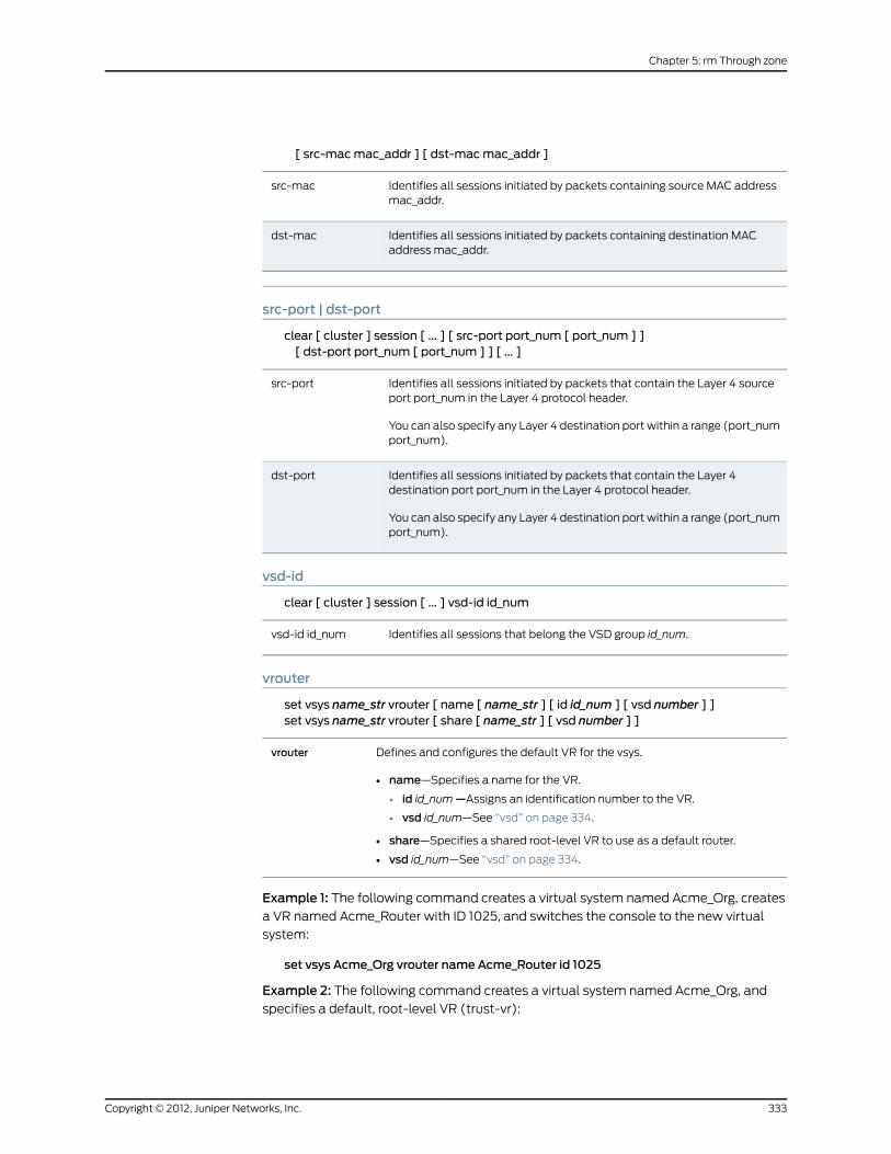
[ src-macmac_addr ] [ dst-macmac_addr ]
Identifies all sessions initiated by packets containing source MAC addressmac_addr.
src-mac
Identifies all sessions initiated by packets containing destination MACaddress mac_addr.
dst-mac
src-port | dst-port
clear [ cluster ] session [ ... ] [ src-port port_num [ port_num ] ][ dst-port port_num [ port_num ] ] [ ... ]
Identifies all sessions initiated by packets that contain the Layer 4 sourceport port_num in the Layer 4 protocol header.
You can also specify any Layer 4 destination port within a range (port_numport_num).
src-port
Identifies all sessions initiated by packets that contain the Layer 4destination port port_num in the Layer 4 protocol header.
You can also specify any Layer 4 destination port within a range (port_numport_num).
dst-port
vsd-id
clear [ cluster ] session [ ... ] vsd-id id_num
Identifies all sessions that belong the VSD group id_num.vsd-id id_num
vrouter
set vsys name_str vrouter [ name [ name_str ] [ id id_num ] [ vsd number ] ]set vsys name_str vrouter [ share [ name_str ] [ vsd number ] ]
Defines and configures the default VR for the vsys.
• name—Specifies a name for the VR.
• id id_num—Assigns an identification number to the VR.
• vsd id_num—See “vsd” on page 334.
• share—Specifies a shared root-level VR to use as a default router.
• vsd id_num—See “vsd” on page 334.
vrouter
Example 1: The following command creates a virtual system named Acme_Org, creates
a VR named Acme_Router with ID 1025, and switches the console to the new virtual
system:
set vsys Acme_Org vrouter name Acme_Router id 1025
Example 2: The following command creates a virtual system named Acme_Org, and
specifies a default, root-level VR (trust-vr):
333Copyright © 2012, Juniper Networks, Inc.
Chapter 5: rm Through zone

set vsys Acme_Org vrouter share trust-vr
vsd
set vsys name_str vrouter [ vsd number ]
Assigns a Virtual Security Device (VSD) group number to the VR. A VSD groupis a pair of physical security devices (a primary and a backup) that collectivelycomprise a single VSD. A VSD provides failover capability, allowing the backupdevice to take over if the primary device fails. For more information about VSDgroups, see the Concepts & Examples ScreenOS Reference Guide.
vsd number
Example: The following command creates a virtual system named Acme_Org, creates
a VR named Acme_Router, creates a VSD ID 5, and switches the console to the new
virtual system:
set vsys Acme_Org vrouter vsd 5
vsys-profile
set vsys name_str vsys-profile name_str
Assigns an existing vsys profile to the vsys. The vsys profile must be previouslydefined.
vsys-profile
vsys-profile
Use the vsys-profile commands to configure virtual system (vsys) profiles. Vsys profiles
allow you to define resource allocation for individual virtual systems by setting a maximum
value and reserved value for resources. The absolute maximum value for a resource
depends on the security device, and the configured maximum value cannot exceed the
device’s absolute maximum value. The reserved value cannot be higher than the maximum
value.
Use theget vsys-profile command to see a list of all vsys profiles and resource allocation
information for each vsys profile.
Syntax
get
get vsys-profile [ name_str | global ]
set
set vsys-profile { name_str | name name_str }[ cpu-weight number ] [ dip-scale-size num ][ dips{max number | reserve number}
][ mips{max number | reserve number
Copyright © 2012, Juniper Networks, Inc.334
IPv6 Command Descriptions

}][ mpolicies{max number | reserve number}
][ policies{max number | reserve number}
][ sessions{alarm numbermax number | reserve number}
][ user-serv-grps{max number | reserve number}
][ user-servs{max number | reserve number}
][ user-zones{max number | reserve number}
][ zone-addr-grps{max number | reserve number}
][ zone-addrs{max number | reserve number}
]
Keywords and Variables
Variables
get vsys-profile [ name_str ]set vsys-profile name_str [ ... ]unset vsys-profile name_str
Name of an existing virtual system (vsys).name_str
335Copyright © 2012, Juniper Networks, Inc.
Chapter 5: rm Through zone

Example: The following command configures a session limit of 500 for the existing
vprofile1 profile:
set vsys-profile vprofile1 sessionsmax 500
cpu-weight
set vsys-profile { name_str | name name_str } cpu-weightweight
Specifies CPU weight, which is a dimensionless quantity used to calculatethe CPU time quota for each vsys. The CPU weight for a vsys is used incombination with the CPU weight for all the other virtual systems in a securitydevice when calculating the time quota.
CPU weight can be a value from 1 through 100. The default value is 50.
cpu-weight
Example: The following command configures a CPU weight of 30 for the existingvprofile1profile:
set vsys-profile vprofile1 cpu-weight 30
dip-scale-size
set vsys-profile profile-name [ dip-scale-size num ]
unset vsys-profile profile-name [ dip-scale-size num ]
Allows the user to specify the maximum scale-size that can be configured innon-root vsys. The dip-scale-size prevents non-root vsys from consumingtoo many port nodes and memory.
dip-scale-size
The dip-scale-size number is 0 to maximum number of root vsys.number
dips
set vsys-profile { name_str | name name_str } dips { max number | reserve number }
Maximum number of dynamic IP addresses (DIPs) per vsys.max
Number of DIPs reserved per vsys.reserve
Example: The following command configures a maximum value of 200 for the existing
vprofile1 profile:
set vsys-profile vprofile1 dipsmax 200
global
get vsys-profile [ global ]
Displays summary of global usage for the whole device.global
Copyright © 2012, Juniper Networks, Inc.336
IPv6 Command Descriptions

mips
set vsys-profile { name_str | name name_str } mips {max number | reserve number }
Maximum number of mapped IP addresses (MIPs) per vsys.max
Number of MIPs reserved per vsys.reserve
Example: The following command configures a reserved value of 500 MIPs for the existing
vprofile1 profile:
set vsys-profile vprofile1 mips reserve 500
mpolicies
set vsys-profile { name_str | name name_str } mpolicies { max number | reserve number}
Maximum number of multicast policies per vsys.max
Number of multicast policies reserved per vsys.reserve
Example: The following command configures a maximum value of 300 for the existing
vprofile1 profile:
set vsys-profile vprofile1 mpoliciesmax 300
name
set vsys-profile name name_str
Name of the vsys profile. The maximum name length is 31 alphanumericcharacters, including hyphens (-) and underscores (_). Spaces and specialcharacters are not permitted.
name
Example: The following command creates a vsys profile named vprofile1:
set vsys-profile name vprofile1
policies
set vsys-profile { name_str | name name_str } policies { max number | reserve number }
Maximum number of security policies per vsys.max
Number of security policies reserved per vsys.reserve
Example: The following command configures a reserved value of 10000 policies for the
existing vprofile1 profile:
337Copyright © 2012, Juniper Networks, Inc.
Chapter 5: rm Through zone

set vsys-profile vprofile1 policiesmax 10000
sessions
set vsys-profile { name_str | name name_str } sessions { alarm number | max number |reserve number }
Number of sessions reached before an alarm is triggered.alarm
Maximum number of sessions per vsys.max
Number of sessions reserved per vsys.reserve
Example: The following command configures a session limit of 500 for the existing
vprofile1 profile:
set vsys-profile vprofile1 sessions 500
user-serv-grps
set vsys-profile { name_str | name name_str } user-serv-grps { max number | reservenumber }
Maximum number of user service groups per vsys.max
Number of user service groups reserved per vsys.reserve
Example: The following command configures a maximum value of 500 user service
groups for the existing vprofile1 profile:
set vsys-profile vprofile1 user-serv-grpsmax 500
user-servs
set vsys-profile { name_str | name name_str } user-servs {max number | reserve number}
Maximum number of user services per vsys.max
Number of user services reserved per vsys.reserve
Example: The following command configures a maximum value of 400 user services for
the existing vprofile1 profile:
set vsys-profile vprofile1 user-servsmax 400
user-zones
set vsys-profile { name_str | name name_str } user-zones {max number | reserve number}
Maximum number of zones per vsys.max
Number of zones reserved per vsys.reserve
Copyright © 2012, Juniper Networks, Inc.338
IPv6 Command Descriptions

Example: The following command configures a maximum value of 450 user service
groups for the existing vprofile1 profile:
set vsys-profile vprofile1 user-zonesmax 450
zone-addr-grps
set vsys-profile { name_str | name name_str } zone-addr-grps { max number | reservenumber }
Maximum number of zone address groups per vsys.max
Number of zone address groups reserved per zone per vsys.reserve
Example: The following command configures a reserved value of 1000 zone address
groups for the existing vprofile1 profile:
set vsys-profile vprofile1 zone-addr-grps reserve 1000
zone-addrs
set vsys-profile {name_str | name name_str } zone-addrs {max number | reserve number}
Maximum number of zone addresses per vsys.max
Number of zone addresses reserved per zone per vsys.reserve
Example: The following command configures a maximum value of 15000 user zone
addresses for the existing vprofile1 profile:
set vsys-profile vprofile1 zone-addrsmax 15000
webauth
Use thewebauth commands to configure the security device to perform WebAuth
authentication.
WebAuth is an authentication method that requires the user to initiate an HTTP session
and input authentication information, before the user can send traffic to the destination
node.
You must specify authentication in policy definitions (see the auth keyword description
in ).
Syntax
get
get webauth [ banner ]
set
set webauth { banner success string | server name_str }
339Copyright © 2012, Juniper Networks, Inc.
Chapter 5: rm Through zone

Keywords and Variables
banner success
get webauth bannerset webauth banner success stringunset webauth banner success
Specifies the banner (string) displayed in response to Webauth success.banner success
Example: The following command changes the Webauth success banner to “ Webauth
service successful” :
set webauth banner success “Webauth service successful”
server
set webauth server name_strunset webauth banner server
Specifies the Webauth server name (name_str). (You can obtain all existingWebauth server names by executing the command get auth-server all.)
server
Example: The following command specifies a Webauth server named “ Our_Webauth”
:
set webauth server Our_Webauth
Defaults
The default banner value isWebauth Success.
webtrends
Use thewebtrends commands to configure the security device for WebTrends.
The WebTrends Firewall Suite allows you to customize syslog reports of critical, alert,
and emergency events to display the information you want in a graphical format. You
can create reports that focus on areas such as firewall attacks (emergency-level events)
or on all events with the severity levels of critical, alert, and emergency.
Syntax
get
get webtrends
set
set webtrends{VPN |enable |host-name name_str |
Copyright © 2012, Juniper Networks, Inc.340
IPv6 Command Descriptions

port port_num}
Keywords and Variables
vpn
set webtrends VPNunset webtrends VPN
Enables WebTrends VPN encryption.vpn
enable
set webtrends enableunset webtrends enable
Enables WebTrends.enable
host-name
set webtrends host-name name_strunset webtrends host-name
Specifies the WebTrends hostname.host-name
port
set webtrends port port_numunset webtrends port
Specifies the WebTrends host port.port port_num
xauth
Use the xauth commands to configure the security device to perform XAuth
authentication.
An XAuth user or user group is one or more remote users who authenticate themselves
when connecting to the security device via an AutoKey IKE VPN tunnel and optionally
receive TCP/IP settings from the security device. Whereas IKE user authentication is
actually the authentication of VPN gateways or clients, XAuth user authentication is the
authentication of the users themselves. It requires each user to enter information unique
to that user (the username and password).
Syntax
get
get xauth { active | default | lifetime }
set
set xauth
341Copyright © 2012, Juniper Networks, Inc.
Chapter 5: rm Through zone

{default{auth server name_str [ chap ] [ query-config ] |dns1 ip_addr | dns2 ip_addr |ippool name_str |wins1 ip_addr | wins2 ip_addr} |
lifetime number}
Keywords and Variables
active
get xauth active
Displays all currently active XAuth login instances.active
default
get xauth defaultset xauth default { ... }unset xauth default { ... }
Sets or displays default XAuth settings.
• auth server —Identifies the XAuth server by object name (name_str).
• chap—Directs the device to use Challenge Handshake AuthenticationProtocol (CHAP) while performing authentication with the XAuth client.
• query-config —Sets query client settings (such as IP address) from theexternal authentication server.
• dns1 —Identifies the DNS primary server by IP address (ip_addr).
• dns2 —Identifies the DNS secondary server by IP address (ip_addr).
• ippool —Identifies the IP pool (name_str).
• wins1 —Identifies the WINS primary server by IP address (ip_addr).
• wins2 —Identifies the WINS secondary server by IP address (ip_addr).
default
Example: The following command sets up the security device to use a XAuth server
(Our_Auth):
set xauth default auth server Our_Auth
lifetime
get xauth lifetimeset xauth lifetime numberunset xauth lifetime number
Specifies the maximum length of time (in minutes) that the XAuth serverholds resources (such as IP address) on behalf of the client.
lifetime number
Example: The following command specifies a maximum XAuth session length of 30
minutes:
Copyright © 2012, Juniper Networks, Inc.342
IPv6 Command Descriptions

set xauth lifetime 30
xlate
Use the xlate command to view translation transmission information. This command
displays the following details:
• IP address
• Port number
• Translated IP address
• Translated port number
• Port count
• Dynamic IP (DIP) ID
• Count
Syntax
get xlate
Keywords and Variables
None.
zone
Use the zone commands to create, remove, or display a security zone, and to set SCREEN
options.
A security zone is method for sectioning the network into segments to which you can
apply various security options. You can configure multiple security zones for individual
security devices, thus dividing the network into segments to which you can apply security
options. There must be at least two security zones per device, basically to protect one
area of the network from the other. On some platforms, you can define many security
zones, bringing finer granularity to your network security design, without deploying multiple
security appliances.
Each security zone has at least one interface bound to it. For a brief description of the
interfaces, see “Interfaces” on page 355. For information about security zones, see “Zones”
on page 357.
Syntax
get
get zone[id id_num |all |zone [ screen { all | attack | counter | info } ]]
343Copyright © 2012, Juniper Networks, Inc.
Chapter 5: rm Through zone

set
set zone{name zone [ { L2 id_num | tunnel zone } ] |zone{asymmetric vpn |block |screen{alarm-without-drop |block-frag |component-block [ activex | java | zip | exe ] |fin-no-ack |icmp-flood [ threshold number ] |icmp-fragment |icmp-large |ip-bad-option |ip-filter-src |ip-loose-src-route |ip-record-route |ip-security-opt |ip-spoofing [ drop-no-rpf-route ] |ip-stream-opt |ip-strict-src-route |ip-sweep [ threshold number ] |ip-timestamp-opt |land |limit-session[ source-ip-based number | destination-ip-based [ number ] ] |
mal-url { string1 string2 number | code-red } |on tunnel |ping-death |port-scan [ threshold number ] |syn-ack-ack-proxy [ threshold number ] |syn-fin |syn-flood[alarm-threshold number |attack-threshold number |destination-threshold number |drop-unknown-mac |queue-size number |source-threshold number |timeout number] |syn-frag |tcp-sweep | [threshold number] |tcp-no-flag |tear-drop |udp-flood [ threshold number ] |udp-sweep | [threshold number] |unknown-protocol |winnuke
Copyright © 2012, Juniper Networks, Inc.344
IPv6 Command Descriptions

}reassembly-for-alg |tcp-rst |vrouter name_str} |
Keywords and Variables
Variables
get zone zone [ ... ]set zone zone { ... }unset zone zone { ... }
The name of the zone. For more information, see “Zones” on page 357.zone
all
get zone all [ ... ]
Displays information about all existing zones.all
asymmetric vpn
set zone asymmetric vpn
When enabled, this option allows any incoming VPN traffic in a zone to matchany applicable VPN session, regardless of the origin of the original VPN tunnel.For example, traffic coming from VPN A can match a session created by trafficfor VPN B. This feature allows free routing of VPN traffic between two or moresites when there are multiple possible paths for VPN traffic.
Note: It is not advisable to mix policy-based and route-based VPNs forasymmetric traffic.
asymmetric vpn
block
set zone zone blockunset zone zone block
Imposes intra-zone traffic blocking.block
name
set zone name zone { ... }
Creates a new zone with name zone.
• L2 id_num—Specifies that the zone is Layer 2 (for running the device intransparent mode). The ID number (id_num) identifies the VLAN to whichthe zone is bound. The name you specify (zone) must begin with “ L2-” .
• tunnel zone—Specifies that the new zone is a VPN tunnel zone, and identifiesthe tunnel-out zone (zone).
name
345Copyright © 2012, Juniper Networks, Inc.
Chapter 5: rm Through zone

Example 1: The following command creates a new Layer 2 zone named L2-Sales, with
VLAN ID number 1:
set zone name L2-Sales L2 1
Example 2: The following command creates a tunnel zone named Engineering and
specifies untrust as the out zone:
set zone name Engineering tunnel untrust
reassembly-for-alg
set zone untrust reassembly-for-alg
Reassembles all fragmented IP packets and TCP segments for HTTPand FTP traffic that arrives at any interface bound to the zone on whichyou enable this option. With this option enabled, the security device canbetter detect malicious URLs that an attacker has deliberately brokeninto packet or segment fragments. Packet and segment reassembly alsoimproves application layer gateway (ALG) filtering by allowing thesecurity device to examine the complete text within payloads.
reassembly-for-alg
screen
set zone zone screen { ... }
Copyright © 2012, Juniper Networks, Inc.346
IPv6 Command Descriptions

set zone zone screen { ... }
Enables or disables firewall services through the interface.
• alarm-without-drop—Generates an alarm when detecting an attack butdoes not block the attack. This option is useful if you allow the attack toenter a segment of your network that you have previously prepared toreceive it—such as a honeynet, which is essentially a decoy network withextensive monitoring capabilities. It does not apply to traffic effected bythe following features when the features have been enabled:
• Session limit
• SYN-ACK-ACK proxy protection
• Malicious URL protection
• block-frag—Enables IP packet fragmentation blocking.
• component-block—Selectively blocks HTTP traffic containing any of thefollowing components:
• activex—ActiveX controls
• java—Java applets
• exe—.EXE files
• zip—ZIP filesAn attacker can use any of these components to load an application (aTrojan Horse) on a protected host, then use the application to gain controlof the host. If you enable the blocking of HTTP components withoutspecifying which components, the security device blocks them all.Alternatively, you can configure the security device to block only specifiedcomponents.
Note: If you enable ActiveX-blocking, the security device also blockspackets containing Java applets, .exe files, and .zip files because theymight be contained within an ActiveX control.
• fin-no-ack—Detects an illegal combination of flags, and rejects packetsthat have them.
• icmp-flood [threshold number ]—Detects and prevents Internet ControlMessage Protocol (ICMP) floods. An ICMP flood occurs when ICMP echorequests are broadcast with the purpose of flooding a system with so muchdata that it first slows down, and then times out and is disconnected. Thethreshold defines the number of ICMP packets per second allowed to pingthe same destination address before the security device rejects furtherICMP packets. The range is 1 to 1,000,000.
• icmp-fragment—Detects and drops any ICMP frame with the MoreFragments flag set, or with an offset indicated in the offset field.
• icmp-large—Detects and drops any ICMP frame with an IP length greaterthe 1024.
• ip-bad-option—Detects and drops any packet with an incorrectly formattedIP option in the IP packet header. The security device records the event inthe SCREEN counters list for the ingress interface.
screen
347Copyright © 2012, Juniper Networks, Inc.
Chapter 5: rm Through zone

• ip-filter-src—Detects and drops all packets with the Source Route Optionenabled. The Source Route Option can allow an attacker to use a false IPaddress to access a network, and receive returned traffic addressed to thereal IP address of the attacker’s host device. The administrator can blockall IP Source Routed frames having Strict Source Routing (or Loose SourceRouting) enabled.
• ip-loose-src-route—Detects packets where the IP option is 3 (Loose SourceRouting) and records the event in the SCREEN counters list for the ingressinterface. This option specifies a partial route list for a packet to take on itsjourney from source to destination. The packet must proceed in the orderof addresses specified, but it is allowed to pass through other routers inbetween those specified.
• ip-record-route—Detects packets where the IP option is 7 (Record Route)and records the event in the SCREEN counters list for the ingress interface.
• ip-security-opt—Detects packets where the IP option is 2 (security) andrecords the event in the SCREEN counters list for the ingress interface.
• ip-spoofing—Prevents spoofing attacks. Spoofing attacks occur whenunauthorized agents attempt to bypass firewall security by imitating validclient IP addresses. Using the ip-spoofing option invalidates such falsesource IP address connections. Only security devices running in NAT orroute mode can use this option. The drop-no-rpf-route option instructsthe security device to drop any packet that is not contained in the routetable, for example, the device drops the packet if it does not contain asource route, or if the source IP address is reserved (non-routable, as with127.0.0.1).
• ip-stream-opt—Detects packets where the IP option is 8 (Stream ID) andrecords the event in the SCREEN counters list for the ingress interface.
• ip-strict-src-route—Detects packets where the IP option is 9 (Strict SourceRouting) and records the event in the SCREEN counters list for the ingressinterface. This option specifies the complete route list for a packet to takeon its journey from source to destination. The last address in the list replacesthe address in the destination field.
• ip-sweep threshold number—Detects and prevents an IP Sweep attack.An IP Sweep attack occurs when an attacker sends ICMP echo requests(pings) to multiple destination addresses. If a target host replies, it revealsthe target’s IP address to the attacker. Set the IP Sweep threshold tobetween 1 and 1,000,000 microseconds. Each time ICMP echo requestsoccur with greater frequency than this limit, the security device drops furtherecho requests from the remote source address.
• ip-timestamp-opt—Detects packets where the IP option list includes option4 (Internet Timestamp) and records the event in the SCREEN counters listfor the ingress interface.
Copyright © 2012, Juniper Networks, Inc.348
IPv6 Command Descriptions

• land—Prevents Land attacks by combining the SYN Flood defensemechanism with IP spoofing protection. Land attacks occur when anattacker sends spoofed IP packets with headers containing the target’s IPaddress for both the source and destination IP addresses. The attackersends these packets with the SYN flag set to any available port. This inducesthe target to create empty sessions with itself, filling its session table andoverwhelming its resources.
• limit-session [ source-ip-based number | destination-ip-based number ]—Limits the number of concurrent sessions the device can initiate from asingle source IP address, or the number of sessions it can direct to a singledestination IP address. By default, the limit is 128 sessions. Limit value rangeis 1 to 49,999.
• mal-URL [ name_str id_str number | code-red ]—Sets up a filter that scansHTTP packets for suspect URLs. The security device drops packets thatcontain such URLs. The code-red switch enables blocking of the Code Redworm virus. Using the name_str option works as follows.
• name_str A user-defined identification name.
• id_str—Specifies the starting pattern to search for in the HTTP packet.Typically, this starting pattern begins with the HTTP command GET,followed by at least one space, plus the beginning of a URL. (The securitydevice treats multiple spaces between the command “ GET” and thecharacter “ /” at the start of the URL as a single space.)
• number—Specifies a minimum length for the URL before the CR-LF.
• on-tunnel—Enables the configured screen functions on the tunnel in thiszone. The default is disabled. Screening applies only to the ingress interface.
On ASIC-based security devices, screen functions performed by the ASICapply to tunnel traffic automatically if the functions are enabled. However,the screening is based on the physical interface the tunnel is bound to. Forroute based VPN tunnels, if the tunnel interface and the physical interfaceare in different zones, the screen functions configured for the zone ofphysical interface apply.
• ping-of-death—Detects and rejects oversized and irregular ICMP packets.Although the TCP/IP specification requires a specific packet size, manyping implementations allow larger packet sizes. This can trigger a range ofadverse system reactions including crashing, freezing, and restarting.
• port-scan threshold number—Prevents port scan attacks. A port scanattack occurs when an attacker sends packets with different port numbersto scan available services. The attack succeeds if a port responds. Toprevent this attack, the security device internally logs the number of differentports scanned from a single remote source. For example, if a remote hostscans 10 ports in 0.005 seconds (equivalent to 5000 microseconds, thedefault threshold setting), the security device flags this as a port scanattack, and rejects further packets from the remote source. The port-scanthreshold number value determines the threshold setting, which can befrom 1000 to 1,000,000 microseconds.
• syn-ack-ack-proxy—Prevents the SYN ACK ACK attack. Such an attachoccurs when the attacker establishes multiple Telnet sessions withoutallowing each session to terminate. This consumes all open slots, generatinga denial of service (DOS) condition.
• syn-fin—Detects an illegal combination of flags attackers can use toconsume sessions on the target device, thus resulting in a denial of service(DOS).
349Copyright © 2012, Juniper Networks, Inc.
Chapter 5: rm Through zone

• syn-flood—Detects and prevents SYN Flood attacks. Such attacks occurwhen the connecting host continuously sends TCP SYN requests withoutreplying to the corresponding ACK responses.
• alarm-threshold number—Defines the number of half-complete proxyconnections per second for which the security device makes entries in theevent log.
• attack_threshold number—Defines the number of SYN packets per secondrequired to trigger the SYN Proxy mechanism.
• destination-threshold number—Specifies the number of SYN segmentsreceived per second for a single destination IP address before the securitydevice begins dropping connection requests to that destination. If aprotected host runs multiple services, you might want to set a thresholdbased on destination IP address only, regardless of the destination portnumber.
• drop-unknown-mac—Drops packets when they contain unknowndestination MAC addresses.
• queue-size number—Defines the number of proxy connection requestsheld in the proxy connection queue before the system starts rejecting newconnection requests.
• source-threshold number—Specifies the number of SYN segmentsreceived per second from a single source IP address (regardless of thedestination IP address and port number) before the security device beginsdropping connection requests from that source.
• timeout number—Defines the maximum length of time before ahalf-completed connection is dropped from the queue. You can set itbetween 1 and 50 seconds.
• syn-frag—Detects a SYN fragment attack and drops any packet fragmentsused for the attack. A SYN Fragment attack floods the target host withSYN packet fragments. The host caches these fragments, waiting for theremaining fragments to arrive so it can reassemble them. By flooding aserver or host with connections that cannot be completed, the host'smemory buffer eventually fills. No further connections are possible, anddamage to the host's operating system can occur.
• tcp-no-flag—Drops an illegal packet with missing or malformed flags field.
• tcp-sweep— Configures the TCP Sweep Protection SCREEN option forthe security device. When the number of packets from a source ID exceedsa threshold rate, the TCP Sweep Protection SCREEN option is enabled andfurther packets originating from that source are dropped.
• threshold number—Defines the number of packets from a source ID toa unique destination IP. If the number of packets exceeds the thresholdrate, the connection with the source is dropped. The default thresholdrate is 50 packets per second. You can configure a value between 1 to5000 packets per second.
• tear-drop—Blocks the Teardrop attack. Teardrop attacks occur whenfragmented IP packets overlap and cause the host attempting toreassemble the packets to crash. The tear-drop option directs the securitydevice to drop any packets that have such a discrepancy.
Copyright © 2012, Juniper Networks, Inc.350
IPv6 Command Descriptions

• udp-floodthresholdnumber—UDP flooding occurs when an attacker sendsUDP packets to slow down the system to the point that it can no longerprocess valid connection requests. The threshold number parameter is thenumber of packets allowed per second to the same destination IPaddress/port pair. When the number of packets exceeds this value withinany 1-second period, the security device generates an alarm and dropssubsequent packets for the remainder of that second. The valid range isfrom 1 to 1,000,000.
• udp-sweep—Configures the UDP Sweep Protection SCREEN option forthe security device. When the number of packets from a source ID exceedsa threshold rate, the UDP sweep Protection SCREEN option iis enabled andfurther packets originating from that source are dropped.
• threshold number—Defines the number of packets from a source ID toa unique destination IP within a particular timeframe. If the number ofpackets exceeds the threshold rate, the connection with the source isdropped. The default threshold rate is 50 packets per second. You canconfigure a value between 1 to 5000 packets per second.
• unknown-protocol—Discards all received IP frames with protocol numbersgreater than 135. Such protocol numbers are undefined or reserved.
• winnuke—Detects attacks on Windows NetBios communications, modifiesthe packet as necessary, and passes it on. (Each WinNuke attack triggersan attack log entry in the event alarm log.)
Example 1:The following command enables the ip-spoofing firewall service for the trustzone:
set zone trust screen ip-spoofing
The following command enables the ip-spoofing firewall service for the untrust zone,
and instructs the device to drop any packet that has no source IP address, or that has a
non-routable source IP address:
set zone untrust screen ip-spoofing drop-no-rpf-route
Example 2: The following command sets up a filter that scans HTTP packets for the
code-red Code Red worm virus and drops such packets.
set zone untrust screenmal-url code-red
Example 3: The following commands block ActiveX and Java applets in HTTP traffic
received on interfaces bound to the Untrust zone:
set zone untrust block-component activexset zone untrust block-component java
Example 4: The following commands limit the number of sessions from any host in the
Trust and Untrust zones to any single IP address to 80 sessions:
set zone trust screen limit-session destination-ip-based 80set zone trust screen limit-sessionset zone untrust screen limit-session destination-ip-based 80set zone untrust screen limit-session
tcp-rst
set zone zone tcp-rst
351Copyright © 2012, Juniper Networks, Inc.
Chapter 5: rm Through zone

unset zone zone tcp-rst
Directs the security device to send back the TCP reset packet when it receivesnon-sync packets.
tcp-rst
vrouter
set zone zone vrouter
Binds the zone to a virtual router (VR).
You can bind a management (MGT) zone to a VR other than the trust-vr (theMGT zone is bound to the trust-vr by default).
vrouter
Creating Interfaces
Example 1: The following commands perform the following tasks:
• Create a new Layer 2 zone named L2-Marketingwith VLAN ID number 1
• Assign physical interface ethernet7 to the zone
• Retrieve zone information
set zone name L2-Marketing L2 1set interface ethernet7 zone L2-Marketing
Example 2: The following commands perform the following tasks:
• Create a new Layer 3 zone named Ext_Dept
• Bind the zone to the untrust-vr VR
• Enable ip-spoofing and tear-drop screening
• Bind interface ethernet4 to the zone
set zone name Ext_Deptset zone Ext_Dept vrouter untrust-vrset zone Ext_Dept screen ip-spoofingset zone Ext_Dept screen tear-dropset interface ethernet4 zone Ext_Dept
Copyright © 2012, Juniper Networks, Inc.352
IPv6 Command Descriptions

PART 3
Appendix
• Interfaces on page 355
• Zones on page 357
353Copyright © 2012, Juniper Networks, Inc.

Copyright © 2012, Juniper Networks, Inc.354
IPv6 Command Descriptions

APPENDIX A
Interfaces
Most security zones exchange traffic with other zones (or with other devices) through
physical interfaces or logical subinterfaces. Table 4 on page 355 lists interface types and
their descriptions.
Table 4: Interface Types
DescriptionInterface Type
aggregaten An aggregate interface, which is a grouping of two physicalinterfaces. An aggregate interface provides interface redundancy, allowingload sharing and failover.
Aggregate
ethernetn A physical ethernet interface, denoted by an interface port nand no slots.
ethernetn1/n2 A physical ethernet interface, denoted by an interface slot(n1) and a port (n2).
Ethernet
mgt An interface bound to the MGT zone.
ha | ha1 | ha2 The name of the dedicated HA port.
Function
vlan1 The interface used for VPNs and management traffic while thedevice is in transparent mode.
Layer 2
loopback.n A logical interface that emulates a physical interface on thedevice. A loopback interface is always in the up state as long as the deviceon which it resides is up.
Loopback
redundantn1 A redundant interface, which is a grouping of physicalinterfaces (each denoted by n1). Redundant interfaces perform interfacefailover.
redundantn1.n2 A logical redundant subinterface.
Redundant
ethernetn1.n2 A logical subinterface, denoted by an interface port (n1)with no slots. The .n2 parameter identifies the logical interface. You createlogical interfaces using the set interface command.
ethernetn1/n2.n3 A logical subinterface, denoted by an interface slot (n1)and a port (n2). The .n3 parameter identifies the logical interface. Youcreate logical interfaces using the set interface command.
Subinterface
355Copyright © 2012, Juniper Networks, Inc.

Table 4: Interface Types (continued)
DescriptionInterface Type
tunnel.n A tunnel interface, used for VPN traffic.Tunnel
Copyright © 2012, Juniper Networks, Inc.356
IPv6 Command Descriptions

APPENDIX B
Zones
Juniper Networks security devices use zones to host physical and logical interfaces,
tunnels, and special-purpose items. Although ScreenOS has a number of default
predefined zones, you can create new zones and configure them to meet the requirements
of your organization. Table 5 on page 357 lists zone types and their descriptions.
Table 5: Zone Types
DescriptionZone Type
Use Layer 2 security zones when the device operates in transparentmode.
• v1-trust The V1-Trust zone, which hosts physical interfaces thatcommunicate with trusted network space.
• v1-untrust The V1-Untrust zone, which hosts physical interfacesthat communicate with untrusted network space.
• v1-dmz The DMZ zone, which hosts the DMZ physical interface.
• name name_str A user-defined Layer 2 security zone. (You createsuch zones using the set zone name name_str L2 command.)
Layer 2
Use Layer 3 security zones when the device operates in NAT or routermode.
• trust The Trust zone, which hosts physical interfaces (and logicalsub-interfaces) that communicate with trusted network space.
• untrust The Untrust zone, which hosts physical interfaces (andlogical sub-interfaces) that communicate with untrusted networkspace.
• globalThe Global zone, which serves as a storage area for mappedIP (MIP) and virtual IP (VIP) addresses. Because traffic going tothese addresses is mapped to other addresses, the Global zonedoes not require an interface.
• dmz The DMZ zone, which hosts the DMZ physical interface.
• name name_str A user-defined Layer 2 security zone. (You createsuch zones using the set zone name name_str command.)
Layer 3
Use tunnel zones to set up VPN tunnels with other security devices.
• untrust-tun The Untrust-Tun zone, which hosts VPN tunnels.
• name name_strA user-defined tunnel zone. You create such zonesusing the set zone name name_str tunnel command.
Tunnel
357Copyright © 2012, Juniper Networks, Inc.

Table 5: Zone Types (continued)
DescriptionZone Type
Use function zones as described below:
• null The Null zone, which serves as temporary storage for anyinterfaces that are not currently bound to another zone.
• self The Self zone, which hosts the interface for remotemanagement connections. For example, when you connect to thedevice via HTTP, SCS, or Telnet, you connect to the Self zone.
• ha The HA zone, which hosts the high-availability interfaces, HA1and HA2.
• mgt The MGT zone, which hosts the out-of-band managementinterface, MGT.
Function
Copyright © 2012, Juniper Networks, Inc.358
IPv6 Command Descriptions

PART 4
Index
• Index on page 361
359Copyright © 2012, Juniper Networks, Inc.

Copyright © 2012, Juniper Networks, Inc.360
IPv6 Command Descriptions

Index
Aaddress book
adding entries...........................................................14, 49
address translation
policies.............................................................................228
addresses
entering.......................................................................14, 49
administration parameters..................................................16
attack actions
close..................................................................................222
drop packet....................................................................222
authentication
polices..............................................................................222
authentication, users.............................................................45
AV
policies.............................................................................222
CCA (certificate authority)
CGI path..........................................................................205
clear..............................................................................................61
interface counters...........................................................61
clear commands
mac-learn........................................................................174
session..............................................................................272
command
clear mac-learn.............................................................174
clear session...................................................................272
exit.......................................................................................84
get config..........................................................................59
get file................................................................................86
get firewall.....................................................94, 188, 287
get lance info..................................................................163
get route..........................................................................257
get system.....................................................................290
get tech-support.........................................................290
get vip..............................................................................304
ping...................................................................................204
reset...................................................................................241
save...................................................................................263
set address.........................................................14, 35, 49
set admin....................................................................16, 59
set alg.................................................................................30
set arp................................................................................36
set audible-alarm................................................58, 290
set auth..............................................................................45
set
dialup-group........97, 118, 240, 302, 316, 318, 339
set domain........................................................................75
set envar.............................................................................77
set flow...............................................................................87
set hostname..................................................................98
set ike.................................................................................99
set interface.....................................................................118
set ippool.........................................................................158
set l2tp..............................................................................159
set mip.............................................................................205
set ntp...............................................................................185
set ospfv3.......................................................................189
set policy..........................................................................218
set proto-dist................................................................234
set scheduler.................................................................267
set service......................................................................269
set session-cache........................................................277
set snmp.........................................................................278
set snmpv3.....................................................................281
set syslog........................................................................287
set timer...........................................................................291
set traffic-shaping mode..........................................293
set user............................................................................298
set vpn...................................................................156, 308
set vsys..................................................................305, 330
configuration settings, saving............................................59
configuration, LKG...............................................................265
console
exiting.................................................................................84
console and command-line interface
exit.......................................................................................84
counter.........................................................................................61
Ddefining
a schedule.......................................................................267
a Service.........................................................................269
policies.............................................................................218
users for authentication...........................................298
displaying
files in flash card memory..........................................86
firewall settings...........................................94, 188, 287
general system information....................................290
361Copyright © 2012, Juniper Networks, Inc.

the static route table..................................................257
VIP settings...................................................................304
Eentries in the alarm table..............................................25, 28
exit command..........................................................................84
Extended ping.......................................................................204
Ffirewall settings, displaying.............................94, 188, 287
flash card
memory.............................................................................86
flow level....................................................................................62
Ggeneral information, displaying......................................290
Get commands
redirect the output of a Get command....................8
get commands
config..................................................................................59
file........................................................................................86
firewall............................................................94, 188, 287
lance info.........................................................................163
route..................................................................................257
system.............................................................................290
tech-support.................................................................290
vip......................................................................................304
Group
user dialup.....................................................................298
HHA
session backup.............................................................229
hostname..................................................................................98
Iid-mode....................................................................................106
IKE
proxy IDs.........................................................................240
IKE ID.........................................................................................299
interface counter......................................................................61
LLKG configuration................................................................265
MMAC table
clearing..............................................................................174
Mapped IP address.............................................................205
Media Access Control (MAC)............................................174
memory allocation status..................................................176
NNetScreen device
setting the hostname..................................................98
network connection check...............................................204
ping...................................................................................204
Oospfv3
enabling...........................................................................189
Ppacket errors.............................................................................63
ping command......................................................................204
policies
address translation.....................................................228
attack objects................................................................222
authentication...............................................................222
AV.......................................................................................222
counting traffic.............................................................223
defining.............................................................................218
disabling..........................................................................224
global................................................................................222
L2TP..................................................................................222
Layer 7 application.......................................................221
logging..............................................................................227
naming.............................................................................227
NAT-dst...........................................................................228
NAT-src............................................................................228
negation..........................................................................228
policy context.................................................................218
reordering........................................................................227
schedule.........................................................................230
session backup.............................................................229
traffic shaping...............................................................232
VPNs.................................................................................232
proxy IDs..................................................................................240
Rreset command......................................................................241
resetting a device..................................................................241
restart NetScreen device....................................................241
reset...................................................................................241
Ssave command......................................................................263
saving a configuration file.................................................263
Copyright © 2012, Juniper Networks, Inc.362
IPv6 Command Descriptions

schedule
creating or modifying..................................................267
schedules
policies............................................................................230
self-log entries.........................................................................171
service
pre-defined....................................................................270
user-defined....................................................................271
Services
creating custom...........................................................269
Session table
clearing.............................................................................272
session-cache
enabling...........................................................................277
set commands
address.................................................................14, 35, 49
admin...........................................................................16, 59
alg........................................................................................30
arp........................................................................................36
audible-alarm.......................................................58, 290
auth.....................................................................................45
dialup-group............97, 118, 240, 302, 316, 318, 339
domain...............................................................................75
envar....................................................................................77
flow......................................................................................87
hostname.........................................................................98
ike.........................................................................................99
interface............................................................................118
ippool................................................................................158
l2tp.....................................................................................159
mip....................................................................................205
ntp......................................................................................185
ospfv3...............................................................................189
policy.................................................................................218
proto-dist........................................................................234
scheduler.........................................................................267
service..............................................................................269
session-cache................................................................277
snmp.................................................................................278
snmpv3.............................................................................281
syslog................................................................................287
timer..................................................................................291
traffic-shaping mode.................................................293
user...................................................................................298
vpn...........................................................................156, 308
vsys.........................................................................305, 330
SNMP
enabling...........................................................................278
SNMPv3
enabling...........................................................................281
SNTP..........................................................................................185
static route table...................................................................257
static route table, displaying............................................257
TTCP
notification.....................................................................229
tftp server.....................................................................................8
traffic shaping
policies.............................................................................232
Transparent mode.................................................................174
troubleshooting....................................................................290
Uuntrusted interface IP address........................................205
user authentication
creating entries...............................................................45
users, creating.......................................................................298
VVIP settings, displaying......................................................304
Virtual IP (VIP)......................................................................304
virtual system
creating.................................................................305, 330
exiting.................................................................................84
VPN (Virtual Private Network)..............................156, 308
363Copyright © 2012, Juniper Networks, Inc.
Index

Copyright © 2012, Juniper Networks, Inc.364
IPv6 Command Descriptions