scott needham 435-764-3480 - ece | · pdf filescott needham needhamizer@gmail ... included is...
TRANSCRIPT

1
Scott Needham [email protected] 435-764-3480 John Snow [email protected] 801-513-4092 Abe Clements [email protected] 208-709-3284 April 15, 2009
YangQuan Chen Department of Electrical and Computer Engineering Utah State University Dear Dr. Chen,
Included is our final report for our senior design project for a home automation system. The
report details the process we went through in designing and implementing our project. The main
purpose of our project was to design a network of sensors and actuators and a user interface which will
allow easy programming of the sensors and actuators to carry out a variety of tasks in the home. We
have successfully implemented and tested our project. The project required the expertise of each team
member. Communication among our team was a key factor in the success of our project. The project
involved several different hardware and software disciplines and was a great learning experience.
Sincerely, Abe Clements John Snow Scott Needham

2
ECE 4850 – UTAH STATE UNIVERSITY
Home Automation System with Green Applications
Senior Design Project Final Report
Abe Clements, John Snow, Scott Needham
4/16/2009
The objective of this senior design project is to design and implement a home automation system of sensors and actuators controlled from a web interface. Sets of sensors and actuators are grouped together to form a node. The system contains temperature, light, and motion sensors. There are also three types of actuators: a motor to control an HVAC damper, a set of switches controlling a home furnace, and a dimmer switch. Wireless communication is achieved with Zigbee radios. Each node sends information about its environment to the host which processes the information. This host communicates with a web server which provides a user interface to the end user. The web interface is user friendly and familiar to most people. The end user is able to monitor data recorded by sensors and set up a custom configuration for controlling the actuators in the system. The entire system gives the user complete control over the home, potentially leading to reduced energy consumption.

3
Table of Contents List of Figures ................................................................................................................................................ 7
List of Tables ................................................................................................................................................. 7
1 Introduction .......................................................................................................................................... 8
1.1 Background ................................................................................................................................... 8
1.2 Problem Statement ....................................................................................................................... 8
1.3 Summary of Design Process .......................................................................................................... 9
1.4 Summary of Results ...................................................................................................................... 9
1.5 Societal Impact and Implications .................................................................................................. 9
1.6 Organization and Summary of Report .......................................................................................... 9
2 Review of Conceptual Design .............................................................................................................. 10
2.1 System Overview......................................................................................................................... 10
2.1.1 Design Specifications & Performance ................................................................................. 10
2.2 Software Components ................................................................................................................ 10
2.2.1 Web Server and User Interface ........................................................................................... 10
2.2.2 Host Software...................................................................................................................... 11
2.2.3 Microcontroller Software .................................................................................................... 11
2.3 Hardware Components ............................................................................................................... 11
2.3.1 TS-7200 Single-Board Computer ......................................................................................... 11
2.3.2 Microcontrollers .................................................................................................................. 11
2.3.3 Wireless Radios ................................................................................................................... 11
2.3.4 Temperature Sensor ........................................................................................................... 12
2.3.5 Light Sensor ......................................................................................................................... 12
2.3.6 Motion Sensor ..................................................................................................................... 12
2.3.7 Thermostat Controller ........................................................................................................ 12
2.3.8 HVAC Duct ........................................................................................................................... 12
2.3.9 Dimmer Switch .................................................................................................................... 12
2.4 Communication Protocol ............................................................................................................ 12
3 Final Design ......................................................................................................................................... 13
3.1 Software Components ................................................................................................................ 13
3.1.1 Web Server and User Interface ........................................................................................... 13
3.1.2 Host Software...................................................................................................................... 13
4
3.1.3 Test Software ...................................................................................................................... 14
3.2 Hardware Components ............................................................................................................... 14
3.2.1 TS-7200 Single-Board Computer ......................................................................................... 14
3.2.2 Microcontrollers .................................................................................................................. 14
3.2.3 Wireless Radios ................................................................................................................... 15
3.2.4 Temperature Sensor ........................................................................................................... 15
3.2.5 Light Sensor ......................................................................................................................... 15
3.2.6 Motion Sensor ..................................................................................................................... 16
3.2.7 Thermostat Controller ........................................................................................................ 16
3.2.8 HVAC Duct ........................................................................................................................... 17
3.2.9 Dimmer Switch .................................................................................................................... 17
3.3 Communication Protocol ............................................................................................................ 17
4 Implementation .................................................................................................................................. 19
4.1 Software Components ................................................................................................................ 19
4.1.1 Web Server and User Interface ........................................................................................... 19
4.1.2 Host Software...................................................................................................................... 23
4.1.3 Microcontroller Software .................................................................................................... 25
4.2 Hardware Components ............................................................................................................... 25
4.2.1 Light/Temperature Node .................................................................................................... 26
4.2.2 Light/Temperature Node Software ..................................................................................... 27
4.2.3 Thermostat/Motion Node................................................................................................... 27
4.2.4 Thermostat/Motion Node Software ................................................................................... 29
4.2.5 HVAC Damper Node ............................................................................................................ 29
4.2.6 HVAC Damper Node Software ............................................................................................ 31
4.2.7 Dimmer Switch Node .......................................................................................................... 31
4.2.8 Dimmer Switch Node Software ........................................................................................... 33
4.3 Communication Protocol ............................................................................................................ 34
4.4 Test Results ................................................................................................................................. 34
5 Scope ................................................................................................................................................... 34
5.1 Lessons Learned .......................................................................................................................... 34
5.2 Future Suggestions ...................................................................................................................... 35
5.2.1 Nodes .................................................................................................................................. 35
5
5.2.2 Host and Web Server .......................................................................................................... 35
5.3 System Life-Cycle ........................................................................................................................ 36
5.3.1 Nodes .................................................................................................................................. 36
5.3.2 Host and Web Server .......................................................................................................... 36
6 Project Management .......................................................................................................................... 36
6.1 Time Management ...................................................................................................................... 36
6.2 Proposed Budget ......................................................................................................................... 37
6.3 Final Budget ................................................................................................................................ 38
6.4 Facilities Utilized ......................................................................................................................... 41
6.5 Personnel Contributions ............................................................................................................. 41
7 Conclusion ........................................................................................................................................... 42
Appendix A: Code for Host Software .......................................................................................................... 43
Action.cpp ............................................................................................................................................... 43
Action.h ................................................................................................................................................... 44
Com_Protocol.h ...................................................................................................................................... 44
Common.h............................................................................................................................................... 46
main.cpp ................................................................................................................................................. 47
node.cpp ................................................................................................................................................. 48
node.h ..................................................................................................................................................... 52
NodeList.cpp ........................................................................................................................................... 54
NodeList.h ............................................................................................................................................... 55
Packet.cpp ............................................................................................................................................... 56
Packet.h ................................................................................................................................................... 59
Radio.cpp ................................................................................................................................................ 60
Radio.h .................................................................................................................................................... 66
Semaphores.cpp ..................................................................................................................................... 66
Semaphores.h ......................................................................................................................................... 67
Timer.cpp ................................................................................................................................................ 68
Timer.h .................................................................................................................................................... 68
Xmlrpc.cpp .............................................................................................................................................. 69
Xmlrpc.h .................................................................................................................................................. 78
Appendix B: Code for Web Server/User Interface ...................................................................................... 78

6
home_automation.install ....................................................................................................................... 78
home_automation.module ..................................................................................................................... 81
Appendix C: Code for Node Software ....................................................................................................... 108
Com_Protocol.c ..................................................................................................................................... 109
Functions.c ............................................................................................................................................ 114
MotionNode.c ....................................................................................................................................... 115
Com_Protocol.h .................................................................................................................................... 120
Functions.h ............................................................................................................................................ 122

7
List of Figures Figure 1: Response of the AMS302(Trough-hole) Ambient Light Sensor ................................................... 16 Figure 2: Screenshot of user interface displaying a list of devices in the system. ...................................... 20 Figure 3: Screenshot of user interface showing list of devices in the system. ........................................... 21 Figure 4: User interface form for creating a new action. ........................................................................... 22 Figure 5: Light and Temperature Sensor Node ........................................................................................... 26 Figure 6: Light and Temperature Sensor Node ........................................................................................... 27 Figure 7: Schematic of Thermostat and Motion Sensor Node.................................................................... 28 Figure 8: Completed Thermostat and Motion Sensor Node....................................................................... 29 Figure 9: HVAC Damper Schematic ............................................................................................................. 30 Figure 10: Completed HVAC Damper .......................................................................................................... 30 Figure 11: Completed Dimmer Switch ........................................................................................................ 32 Figure 12: Dimmer Switch Schematic ......................................................................................................... 33 Figure 13: Oscilloscope View of the dimmer switch control ...................................................................... 34 Figure 14: Gantt Chart ................................................................................................................................ 37
List of Tables Table 1: Packet structure and description of each byte. ............................................................................ 18 Table 2: List of commands. ......................................................................................................................... 18 Table 3: Types of measurements. ............................................................................................................... 19 Table 4: Escaping of special characters in data bytes. ................................................................................ 19 Table 5: Proposed budget ........................................................................................................................... 38 Table 6: Final Total Budget ......................................................................................................................... 39 Table 7: Host Cost ....................................................................................................................................... 39 Table 8: Light and Temperature Node Cost ................................................................................................ 40 Table 9: Thermostat Node Cost .................................................................................................................. 40 Table 10: 10 HVAC Damper Node Cost ....................................................................................................... 41 Table 11: Dimmer Switch Node Cost .......................................................................................................... 41

8
1 Introduction
1.1 Background Despite the prevalence of technology in our society, there are still areas where technology has not been fully utilized. Wireless sensing technology has been available for years, but its potential is not fully realized. One obstacle that prevents wide spread use of remote sensing is the difficulty of installing and configuring networks of remote sensing devices. Another obstacle is the cost of developing and deploying a custom system for each application. One application where the use of remote sensing technology can impact everyday life is home automation.
Home automation is a growing field enabling people to use technology to increase the comfort and security of their homes. Very few homes use automation systems and many of the systems that are created today are targeted towards newly built homes. Older homes are less energy efficient. Retrofit- able home automation systems can improve the energy efficiency of these homes. This year the news and media are flooded with the world’s need for energy conservation and efficiency.
Home automation can reduce the energy needs of homes and businesses. For example, homes are often heated and cooled when no one is inside. In addition, many lights and electronic devices are left on unnecessarily.
There are a variety of home sizes that employ different heating and lighting devices. A home automation system that is able to adapt to the different sizes and types of homes would be much easier to market. A system that is scalable would be easier for an engineer to target towards a specific home. For a home automation system to be successful it must be user friendly, easy to install, scalable and affordable.
1.2 Problem Statement To meet the requirements of a successful home automation system it is proposed to create a wireless sensing and environment manipulation platform. This platform will provide a set of tools and devices from which user friendly, and scalable automation systems can be quickly developed. Demonstrations of the platform will be aimed at home automation, but many other applications could be implemented with the platform.
The platform will consist of a network of sensors and actuators. A programmable application interface for the sensors and actuators will allow developers to quickly create automation systems. The sensors will communicate wirelessly to a central embedded system. The central system will be responsible for defining the interactions of the sensors and actuators. In addition the central system will provide a user interface. A user will be able to configure the system to fit his or her needs. The interface for the program will be web based with the intention of being user-friendly. A web interface not only takes advantage of people’s familiarity with Internet technology, but also has other advantages. It provides flexibility in designing interfaces, as well as platform independence. We will design two applications to

9
demonstrate the system’s capabilities and potential for saving energy. Those two applications are controlling a furnace and lighting.
1.3 Summary of Design Process After review of the goals of the entire system the requirements of each node were defined. Much research in parts and protocols was devoted to find the best ways to fulfill these requirements. When this was done the topology of the network of nodes and the host was designed. Each node was designed individually in order to meet their different specifications. As implementation began some changes were made to the initial design in order make certain features function.
1.4 Summary of Results All parts of the system successfully meet the requirements of the problem statement. Unforeseen changes were made in order to better meet the requirements including choosing some different hardware parts. Each part of the system was tested separately and also together it meets the constraints that were previously outlined.
1.5 Societal Impact and Implications With the use of this system of integrated sensors and actuators it will help move home automation into the mainstream. After some configuration the end user could set up a program that will save a significant amount of energy. Most people are comfortable with a web interface because they deal with the web in other aspects of their life. This will make the system more approachable and increase the effectiveness that a user could implement a custom configuration that fits their needs.
Billions of dollars are being spent to research energy conservation and new forms of energy. This system represents a low cost way that anyone could put into their home and waste much less energy. With widespread use this system could save a significant amount of energy and the end user will have a much lighter impact on the environment.
Often people leave their homes with the furnace on or with lights on. With this system there are multiple ways to approach this problem. From anywhere in the world a user can see the state of their home and make changes to it through the web. This type of control is yet to be commonplace and can easily become an enriching part of each home.
Through the use of the designed application program interface the system is extensible in size and capability. The host can add nodes without much difficulty and additional sensors such as a sound sensor or smoke sensor can easily be added to the system and give additional features to the system. This makes the system retrofit-able and so will be suitable for homes into the future.
1.6 Organization and Summary of Report This report gives a review of the conceptual design of the project followed by the details of the final design. It then explains in detail how the project was implemented and tested. Details of the project management and budget are also included, followed by concluding remarks.

10
2 Review of Conceptual Design
2.1 System Overview This system includes several sensors and actuators that could be used in a typical home. Each sensor or actuator is contained on a node. These nodes contain a microcontroller and wireless radio that allow them to communicate with a central computer. This computer is called the “host”. The software running on the host gathers data from the sensors to inform the user about the environment. This information is sent to a web server. The web server provides a user interface. This interface allows the user to control the actuators based on the current conditions of the sensors.
2.1.1 Design Specifications & Performance The host software must be capable of both sending data to and receiving data from the remote devices. The host must process data in real time. The host must also provide the ability to log data from the sensors.
The web server software must provide a user interface though which the system can be controlled and monitored. The interface must be user friendly. The web server must also provide a way for the host software to communicate with it.
The sensors must provide the user with the ability to monitor climate and lighting.. These sensors include temperature, ambient light, and motion sensors. Each must be able to obtain and transmit its acquired measurements to the host. They must also be able to receive and process any data from the host that may be needed to accomplish its given task.
The actuators needed to control climate and lighting must be able to perform their required tasks. The needed actions include: the ability to open and close a forced HVAC air duct, turning on and off a furnace and air conditioner, and control the brightness of an incandescent light bulb. These actuators must be capable of receiving commands from the host and executing those commands. They must be able to report any needed information to the host that is necessary for the actuator to carry out its tasks and for the system to be functional.
2.2 Software Components
2.2.1 Web Server and User Interface The first purpose of the web server component is to provide a user interface to the system. The user interface can be accessed from any web browser. The interface should be user-friendly and intuitive. The user interface allows the user to view data that has been collected by sensors. It also allows the user to customize and control the system. Users are able to set up rules such as “If Temperature Sensor A is reading less than 70 degrees, then turn on Light A and turn on the furnace.” Using this interface, the condition of any number of sensors in the system can be used to trigger an action to be performed by any actuators in the system.
The second purpose of the web server is to store persistent data. The web server receives data sent by the host software. This data contains information about what sensors and actuators are available in the
11
system. The data also contains values measured from sensors. The web server also sends configuration data to the host software when the data is requested.
2.2.2 Host Software The host software communicates wirelessly with nodes that contain sensors and actuators. It receives sensor measurements being sent from nodes. It also transmits signals to nodes to trigger actions to perform on actuators. The host software keeps track of all the nodes in the system. Being able to send and receive data in real time is an important requirement of the system. The host software also occasionally requests configuration data from the web server.
2.2.3 Microcontroller Software The microcontroller is what will control the multiple parts to each node. It will read the values that the sensors from the sensors. Reading the data may involve interfacing to both analog and digital components. It will then packetize this information and send it to a wireless radio which in turn sends it to the host. The microcontroller will also receive commands from the host that will dictate how it wishes to use the actuators. The host will also send commands to tell the microcontroller how often to send measurements of the sensors.
Some of the sensors will have real time constraints. The sensor will need a calibrated timer to assure things are computed in the correct order. The microcontroller will respond to the changes in the environment that it will detect through its sensors. For example it will need to respond when the motion sensor detects motion.
2.3 Hardware Components
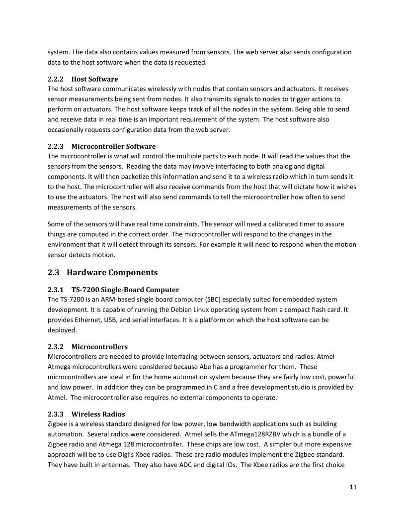
2.3.1 TS-7200 Single-Board Computer The TS-7200 is an ARM-based single board computer (SBC) especially suited for embedded system development. It is capable of running the Debian Linux operating system from a compact flash card. It provides Ethernet, USB, and serial interfaces. It is a platform on which the host software can be deployed.
2.3.2 Microcontrollers Microcontrollers are needed to provide interfacing between sensors, actuators and radios. Atmel Atmega microcontrollers were considered because Abe has a programmer for them. These microcontrollers are ideal in for the home automation system because they are fairly low cost, powerful and low power. In addition they can be programmed in C and a free development studio is provided by Atmel. The microcontroller also requires no external components to operate.
2.3.3 Wireless Radios Zigbee is a wireless standard designed for low power, low bandwidth applications such as building automation. Several radios were considered. Atmel sells the ATmega128RZBV which is a bundle of a Zigbee radio and Atmega 128 microcontroller. These chips are low cost. A simpler but more expensive approach will be to use Digi’s Xbee radios. These are radio modules implement the Zigbee standard. They have built in antennas. They also have ADC and digital IOs. The Xbee radios are the first choice
12
despite their increased cost. None of the member of the team has experience with PCB design and using the ATmega128RZBV would require a PCB.
The 2.4 GHz Xbee module from Digi provides a simple interface for implementing wireless communication. It follows the IEE 802.15.4 standard. The XBee module is a low-power, low bandwidth package that is ideal for this application. XBee modules have a 300 foot range and provide 128-bit encryption.
2.3.4 Temperature Sensor The temperature sensor needs to be able to monitor temperature ranges that are common in the home. In extreme cases temperature variations would be from about 40o F to 110o F. In addition it needs to be precise and accurate enough to maintain a comfortable temperature in a home. The DS18B20 1-Wire digital temperature sensor from Maxim IC provides accuracy of ±0.5°C and a range from -55°C to 125°C. It is also low power and requires no additional components.
2.3.5 Light Sensor The sensitivity of the light sensor needs to similar to the human eye. This is because the light sensor will be used to create a system to control the brightness of a light. The light sensor also needs to operate at low power.
2.3.6 Motion Sensor The motion detector will be used to detect the presence of a person in an area. To accomplish this, the sensor will need to be capable of detecting motion from about 20 feet away. It also needs to have minimal power requirements Sparkfun’s SEN-08630 PIR motion sensor meet these requirements and requires 3.3V to operate.
2.3.7 Thermostat Controller The furnace controller (thermostat) will be responsible for turning on the various stages of typical residential furnace. A typical thermostat has components to turn on AC stages 1 and 2,a fan only stage and a heat stage. The control lines are typically 24V AC to 36V AC. Thus the furnace controller will need be able to switch 4 AC lines. Power transistors or solid state relays SSR will enable this control. Ideally optically isolated SSR or transistors will be used to provide isolation between the AC control lines of the furnace and the DC supply of the microcontroller and radio.
2.3.8 HVAC Duct The HVAC Damper will needs the capability to open and close a HVAC duct. To do this it will need to able to fit in a HVAC duct and open and close the louvers. An existing damper can be retrofit with a motor and mechanics to open and close the louvers of the damper.
2.3.9 Dimmer Switch The dimmer switch will need to be able to dim an incandescent light bulb connected to a 120 AC volt outlet. All electronics used in the dimmer switch should also be powered from the outlet. Dimming of the light must reduce the power consumption of the light.
2.4 Communication Protocol

13
The communication protocol must specify a procedure to follow when information must be exchanged between the host and a node. The procedure should ensure reliable communication between devices. The procedure must specify how to detect errors and what to do if they occur.
A packet structure must be defined. The structure must allow the software to do the following:
• Determine which device the packet came from. • Determine which device the packet is being sent to. • Determine which sensor or actuator the device applies to. • Determine whether the information in the packet represents measurement, command, or
event. • Retrieve data for processing. • Determine how to interpret the data contained in the packet.
3 Final Design
3.1 Software Components
3.1.1 Web Server and User Interface The web server component was programmed in PHP using the web development framework, Drupal. This framework was selected because it provides a way to rapidly develop web applications. In addition John has previous experience working with the Drupal framework. Drupal is free open-source software. Persistent data is stored in a MySQL database.
This component provides a user interface that allows the user to configure and control the system. The user interface is rendered in a web browser using XHTML and CSS. The user interface generates charts and graphs that allow the user to visualize data that has been collected from sensors. The web server also converts raw sensor readings into formats that are understandable by the user.
The user interface allows the user to specify the conditions under which certain actions are performed in the home automation system. Users may specify what values must be read from sensors before an action is executed. Users may also specify a date range and/or a time range in which the action may be performed. This interface is powerful and flexible. It allows any number of conditions to trigger actions on any number of actuators.
An XML-RPC server was also implemented to allow the host software to communicate with the web server. The host functions as an XML-RPC client. XML-RPC is a specification that allows software running on different operating systems to make procedure calls over the internet. It provides a simple way to transfer complex data structures between environments. This allows the web server to receive data from the host and to send data back to the host.
3.1.2 Host Software

14
The host software was programmed using C++ and runs on Linux, making the software portable to desktop and embedded environments. The host software sends and receives data over an XBee radio connected via a serial port. In order to asynchronously receive data and process it in real-time, the application runs on multiple threads.
On startup, the host requests configuration information from the web server. This information tells the software what sensors and actuators are in the system and what nodes they are on. It also provides the software with a list of actions. Each action contains a list of conditions that must be met before that action can be fired and a list of packets to be sent when those conditions are met. The configuration information also sets the sample rate and number of sensor samples to average into one measurement. The configuration is requested periodically for as long as the host software is running.
The host software averages each sample received from a sensor. Once a specified number of samples have been averaged into a measurement, it is added to a list of measurements. As soon as twenty measurements have been received, those measurements are sent to the web server. This prevents the software from making too many HTTP requests to the web server. HTTP requests take an arbitrary amount of time and can slow down the system, so limiting the number of requests made to the web server keeps the host software running efficiently.
3.1.3 Test Software A Windows application was written in C# using the Microsoft .NET framework to test the performance of the host software. The software simulates the behavior of a node that contains an arbitrary number of sensors. This is used to create any number of virtual sensors that all transmit data to the host software. This allows a much larger number of sensors to be simulated than could be purchased and built within the scope of this project.
3.2 Hardware Components
3.2.1 TS-7200 Single-Board Computer The preliminary design specified that the host software would be deployed on a TS-7200 SBC running Debian Linux. Due to difficulties in getting the operating system running on the TS-7200 and time constraints, this specification was dropped from the design. The host software still runs on Debian Linux and could be cross-compiled and deployed on an embedded device running Linux.
3.2.2 Microcontrollers The Atmega 168V microcontroller was selected because of its, low cost, low power requirements, availability in a DIP package, generous memory, and large operating voltage range. The Atmega 168V microcontroller operates on voltages from 1.8 V to 5.5 V and use about 250 µA when running at 4Mhz and 1.8V. The nodes all use the internal oscillator running at 8 Mhz. The Atmega 168V has 16KB of program memory, 512B of EEPROM, and 1KB of RAM. It can also execute nearly one million instructions per mega hertz. Thus nearly 8 million instructions can be executed in one second on the nodes. The Atmega 168V also has an 8 channel 10bit ADC, three internal timers/counters, hardware USART, pin change interrupts and timer interrupts. The Atmega 168V has more memory and features than are utilized by the nodes. It was still selected because the size of the programs to be run on the
15
microcontroller was not known at when the components were select and it was determined that it was better to error on the side of extra memory. In addition, Abe already had a programmer for the Atmega microcontrollers reducing the development costs.
3.2.3 Wireless Radios Digi’s Xbee(XB24-ACI-001) radios were selected for communication with the host. While the ATmega128RZBV would have combined the radio and microcontroller the ATmega128RZBV would have required many external components and a custom PCB. The cost savings would have been very small after including the external components and PCB design. The small savings would have come at a great expense in time. For this reason it was decided to use the XB24-ACI-001 from Digi. The XB24-ACI-001 radio requires voltages between 2.1V and 3.6V. They have an indoor range of approximately 40m, and require about 38mA of current to both transmit and receive. They can support bandwidths of 1200bps to 250kbs. Thus the radios meet the power and bandwidth requirements of our design. The radios have several modes of operation including an API mode, AT command mode, and transparent mode. The radios also have several analog to digital converters (ADC) and digital I/O ports. These can only be used in API mode. Some of the actuators would require more complicated functionality than would be possible using the API mode. For this reason it was decided to use a microcontroller with these devices.
To unify communications between all devices it was determined to use microcontrollers on each node with the radios in transparent mode. This causes them to behave like a standard RS232 serial port. The XBee radios used by each node are configured to only send data to the XBee radio being used by the host software. This prevents each node from seeing packets being sent by other nodes and being overloaded by the amount of data being received. The XBee radio used by the host is configured to broadcast to all nodes.
3.2.4 Temperature Sensor The temperature sensor selected is Microchip’s MCP9700A analog temp sensor. It outputs 0.5V at 0oC and has gain of 10mV per degree C. Thus by using a 1 V reference on the ADC temperatures from -40oC (-40oF) to 50oC (122oF). This exceeds the range needed for temperature measurements in a home. The accuracy of the MCP9700A is ±2oC without calibration. Though calibration it can be improved to ±0.5oC which is sufficient to maintain a comfortable temperature within a home. The temperature sensor has internal signal conditioning circuitry enabling it to be connected directly to the µC and only needs 6µA of current and can operate from 2.3V to 5.5V. The DS18B20 temperature sensor was decided against because of its complicated communication interface. In addition the DS18B20 cost 10 times more than the MCP9700A and has similar range and accuracy. Ultimately, the MCP9700A was selected because of its low cost, simple interfacing, and its ability to meet the requirements of the design.
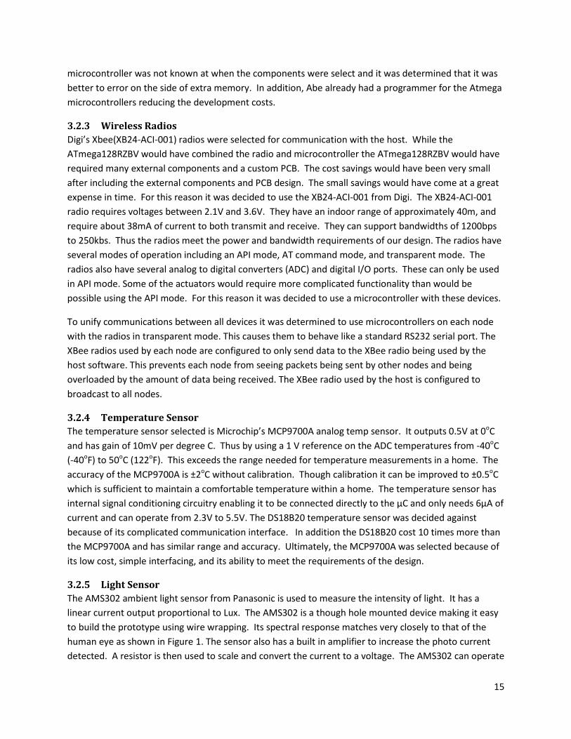
3.2.5 Light Sensor The AMS302 ambient light sensor from Panasonic is used to measure the intensity of light. It has a linear current output proportional to Lux. The AMS302 is a though hole mounted device making it easy to build the prototype using wire wrapping. Its spectral response matches very closely to that of the human eye as shown in Figure 1. The sensor also has a built in amplifier to increase the photo current detected. A resistor is then used to scale and convert the current to a voltage. The AMS302 can operate

16
from 1.6V to 6V using 40mW of power, making it suitable for low power battery operations. In addition the power for the AMS302 is provided though the µC, which allows it to be turned off to reduce power consumption of the node. The APDS-9005-020 from Avago Technologies was considered it has similar performance to the AMS302 lower cost, ultimately it was decided against because it is only available in surface mount packaging.
Figure 1: Response of the AMS302(Trough-hole) Ambient Light Sensor1
3.2.6 Motion Sensor It was decided to operate most of the sensors off of two AA batteries. Thus the motion sensor needs to operate off 3V. No PIR modules could be found that had an operating voltage of 3V. For this reason it was decided to build a motion sensor using a pyro sensor that was obtained surplus. When the sensor was connected the microcontroller motion was not able to be accurately detected. At this point a local source for a PIR motion sensor needed. The 555-28027 PIR motion sensor from Parallax was found at Radio Shack. This sensor can detect motion from 20 feet away. Its data sheet specifies operating voltages of 3.3V to 5V, but testing shows that it operates reliably at 2.8V. This allows it to operate off two AA batteries. It also uses less than 100µA of current. In the end the 555-28027 PIR motion sensor meets the requirements of the design and uses less power than Sparkfun’s SEN-08630 PIR motion sensor.
3.2.7 Thermostat Controller ASSR-1228-002E solid state relays from Avago Technologies were selected to control the furnace. The ASSR-1228-002E contains two form A relays in each package. The relays are optically isolated and turn on with 20mA of current. They are rated for 60V and 200mA. They also are low cost.
1 From Panasonic AMS 302 Data Sheet

17
3.2.8 HVAC Duct The HVAC damper was created by retrofitting an old damper with a motor and drive mechanics. The motor, drive belt and pulleys were salvaged from an old CD Rom drive. The motor is controlled using an H-bridge built from two FQP2P25 N channel MOSFETs, two STF12PF06 P channel MOSFETs and two generic N channel MOSFETs. The FQP2P25 and STF12PF06 were chosen for their large current rating, low on resistance, and low cost. The generic N channel MOSFETs were needed so that the microcontroller operating at 3 volts could control the H-bridge operating at 6V. They were selected because of their availability.
3.2.9 Dimmer Switch Several designs for the dimmer switches were considered. All of the designs used a triac to switch the 120 VAC supply to the light bulb. The basic concept was to delay the turning on of the triac from the zero crossing of the AC supply, thereby reducing the average power supplied to the light. The initial design was to use an RC circuit to create a phase offset between terminal and gate of the triac. This was to be done with a digital potentiometer to change time constant of the RC circuit. It was discovered that digital potentiometer are not designed to withstand reverse voltages. The second design was to use capacitors and solid state relays to switch in additional capacitance to change the delay of the circuit. This approach was abandoned because of it high component count and the difficulty of creating phase of sets. The final design uses an optical coupler and an AC line monitor. The MOC3012M opto coupler from Fairchild Semiconductor was chosen because of its low cost, and non-zero crossing optical triac. The non- zero crossing feature of the triac makes it capable of turning on at any time in the AC cycle. The MOC3012M phototransistor opto coupler from Fairchild Semiconductor is used as an AC line monitor. It is used to generate a pulse that can be detected by the microcontroller at each zero crossing of the AC line. It was selected for its low cost, small size and ease of use. The triac select is the BTA24-800BWRG from STMicroelectronics. It is rated for 800V and 25A. Thus it can easily power a 100W light bulb. In addition most homes have 15 A or 20 A circuit breakers giving the triac some margin when used in residential applications.
3.3 Communication Protocol The following specifications define the procedure to be followed when communicating between the host and a node:
• If a node receives a packet intended for it, then it must reply with an 'Acknowledge’ packet. • If the host does not receive an acknowledge packet within a certain amount of time, then the
packet will be sent again. • Every packet must end with a carriage return character to signify the end of a packet.
Packets being sent from the node to the host do not need to be acknowledged because nodes are continually sending sensor measurements to the host, so if a measurement is occasionally lost, it does not affect the performance of the system.
Each packet is 10 bytes long. The information represented by each byte is given in the table below.

18
Byte Number
Name Description
0 Type Describes the type of packet: • C – Command • M – Measurement • E – Event
1 ID Tells how the data bytes should be interpreted. 2 Device Number Each sensor or actuator on a node is assigned a unique device
number. 3 Escape Contains used to indicate if Data 1 or Data 0 is a zero or a carriage
return 4 Data 1 Contain data such as sensor measurements. 5 Data 0 6 Destination 1 Contain the destination address of the packet. 7 Destination 0 8 Source 1 Contain the source address of the packet. 9 Source 0 Table 1: Packet structure and description of each byte.
If the packet type is a “Command”, then the ID byte (byte 1) will describe which of command it is. A list of commands is given in the table below.
Commands Byte 1 Byte 2 Byte 4 Byte 5 On (Open) O Device No. 0xFF 0xFF Off (Close) F Device No. 0x00 0x00
Set Sample Rate R Device No. Value1 Value0 Clear to Send C 0xFF 0xFF 0xFF
Query Q Device No. 0xFF 0xFF Need to Identify N 0xFF 0xFF 0xFF
Done D 0xFF 0xFF 0xFF Error E Device No. ErrorNum1 ErrorNum0
Num Devices U 0xFF Value1 Value0 Identify I Device No. S or A Device Type Request
Measurement M Device No 0xFF 0xFF
Increase + Device No. %increase %increase Decrease - Device No. %decrease %decrease
Set S Device No. % of 100 %100 Table 2: List of commands.
If the packet type is a “Measurement” or “Event”, then the ID byte will describe what type of sensor the measurement or event came from. The following table lists the types of possible measurements.
Measurement B1 B2 B4 B5 Temp T Device No. Value1 Value0
Motion M Device No. Value1 Value0

19
Button/Switch B Device No. Value1 Value0 Light L Device No. Value1 Value0
Current C Device No. Value1 Value0 Table 3: Types of measurements.
The escape byte (Byte 3) is used to escape special characters that could occur in the data bytes. Both the carriage return (0x0D) and the null character (0x00) must be escaped. The upper four bits of the escape byte tell if and how either of the data bytes was escaped. The lower four bits of the escape byte are always 1. The following table shows how the bits are set to escape characters in the data bytes.
Data Byte Character (Hex) Set Bit Most Significant 0x00 7 Most Significant 0x0D 6 Least Significant 0x00 5 Least Significant 0x0D 4
Table 4: Escaping of special characters in data bytes.
4 Implementation
4.1 Software Components
4.1.1 Web Server and User Interface
4.1.1.1 User Interface The web-based user interface allows users to monitor and control the system from any web browser. The Forms API found in the Drupal framework was used to generate the web forms necessary for this interface.
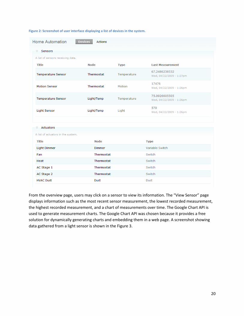
After authenticating themselves with a username and password, users may navigate to the “Home Automation” section of the website. The initial page in this section gives the user an overview of the devices found in the system. It lists all the sensors and actuators in the system and tells which node they can be found on as well as the most recent information received from the device. A screenshot of this page is shown in Figure 2.
20
Figure 2: Screenshot of user interface displaying a list of devices in the system.
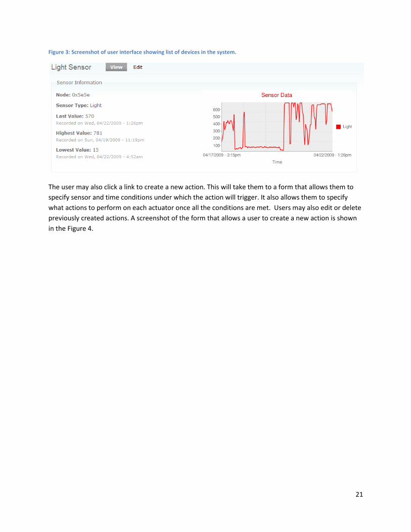
From the overview page, users may click on a sensor to view its information. The “View Sensor” page displays information such as the most recent sensor measurement, the lowest recorded measurement, the highest recorded measurement, and a chart of measurements over time. The Google Chart API is used to generate measurement charts. The Google Chart API was chosen because it provides a free solution for dynamically generating charts and embedding them in a web page. A screenshot showing data gathered from a light sensor is shown in the Figure 3.
21
Figure 3: Screenshot of user interface showing list of devices in the system.
The user may also click a link to create a new action. This will take them to a form that allows them to specify sensor and time conditions under which the action will trigger. It also allows them to specify what actions to perform on each actuator once all the conditions are met. Users may also edit or delete previously created actions. A screenshot of the form that allows a user to create a new action is shown in the Figure 4.

22
Figure 4: User interface form for creating a new action.

23
The user interface meets the requirements of providing information to the user about the state of all components in the system, allowing the user to control the system, and being accessible from any computer with internet access and a web browser.
4.1.1.2 XML-RPC Server The Drupal module, Services, was used to implement the XML-RPC server. The host software must request a session ID before making any remote procedure call to the server. That session ID is used to authenticate subsequent procedure calls to the server. The session ID expires after 30 seconds, after which time the host software must request a new session ID before making further requests. This keeps the server more secure from hackers and replay attacks. All remote procedure calls were tested with the built-in test feature provided by the Services module. The XML-RPC server meets its requirements of allowing the host software to store data and request configuration information.
4.1.2 Host Software The host software executes using two separate threads of control concurrently. The first thread is used for asynchronously receiving input from the XBee radio. The POSIX-supported canonical input processing mode is used to read data from the serial port. This means that input is processed in lines terminated by the carriage return character. The code used to implement this thread is as follows:
while (STOP==FALSE) { semTake(inputSemID, inputSemBuf);
n = read(FileDescriptor,buffer,11); if (n > 0) { buffer[n] = 0x00; tempString = buffer; cout << "Received Data: " << tempString << endl; } if (n == PACKET_LENGTH) { // Received a packet. Received.push_back(tempString);
} else if (n == 9 && tempString.compare(0, 8, "shutdown") == 0) STOP=TRUE; /* stop loop */ }
As can be seen from the code, the thread is blocked until its semaphore is release. The semaphore is released by a signal handler function that is called whenever a carriage return character is detected by the serial port. Upon receiving data that is the length of a packet, that data is added to a list of packets received. That list is processed in the second thread.
The second thread is used for processing input and for sending data out the radio. To achieve this, the following C++ classes were implemented:
• Action – An object representing actions to be performed on actuators. • Node – An object representing a physical node with sensors and actuators. • NodeList – An object that contains a list of all nodes in the system. • Packet – An object that represents a packet.

24
• Timer – An object used to keep track of time. • SensorCondition – An object used to determine whether actions should be triggered. • Device – An object representing a sensor or an actuator.
First, a packet is popped off the front of the list and checked to make sure it is a valid packet. The following code shows how this was implemented:
if (Received.size() > 0) { LastPacket = Received.front(); if (LastPacket.CheckValid()) { cout << "\nReceived Packet: " << LastPacket.packetString << endl; LastPacket.print(); Nodes.AddPacket(LastPacket); } else { cout << "\nReceived invalid packet.\n"; } Received.pop_front(); }
If the packet is valid, then the packet is added to the node object corresponding to the node that sent the packet. The node object then handles the packet appropriately. If a packet is received from an unknown node, then a new node object is created and a “query” packet sent to that node. Once a packet is sent to a node, a timer is started. If the node does not send an “acknowledge” packet in response, before a certain amount of time, the packet is sent again. If a node object receives and “identify” packet, a new device object is created for the device that is being identified. Each node objects keeps a list of device objects. Each device object keeps a list of sensor condition objects. If a measurement packet is received, the device object checks if the value of the measurement meets its sensor conditions. If the sensor conditions are met, then the corresponding packets are sent to the appropriate nodes to trigger actions on the actuators.
This thread also uses a timer to make sure that the web server is queried for configuration data every 60 seconds. Also, every time twenty sensor measurements have been accumulated, they are all sent to the web server at once.
The XMLRPC-C and Libwww libraries were used to implement the remote procedure calls to the web server. These libraries take care of formatting to and parsing data from the XML format. They also handle the HTTP requests to the web server. The XMLRPC-C library allows complex data types to be transferred to and from the web server. An example of a remote procedure call used to send information about a sensor to the web server is given by the following code:
void xmlrpc_add_sensor(uint16_t NodeID, uint8_t DeviceID, uint8_t DeviceType, uint8_t Type) { string sessionID; sessionID = xmlrpc_get_session(); cout << "Session ID: " << sessionID << endl;

25
try { string const methodName("home_automation.add_sensor"); string temp1; string temp2; temp1 = (char)DeviceType; temp2 = (char)Type; xmlrpc_c::clientSimple myClient; xmlrpc_c::value result; myClient.call(serverUrl, methodName, "siiss", &result, sessionID.c_str(), NodeID, DeviceID, temp1.c_str(), temp2.c_str()); bool saved = xmlrpc_c::value_boolean(result); if (saved) { cout << "Device saved to web server." << endl; } } catch (girerr::error const error) { cerr << "Client threw error: " << error.what() << endl; } catch (...) { cerr << "Client threw unexpected error." << endl; } }
A Windows application was written to simulate the behavior of a node containing many sensors sending large amounts of data to the host software. The host software meets its requirements of being able to wirelessly receive large amounts of data, process that data, and produce the correct response quickly.
4.1.3 Microcontroller Software In order for the Atmega 168V µC to run a program a compiler and boot loader are required. AVR studio served this purpose with the mkII programmer. AVR studio’s compiler allows some functionality of the C standard library. More importantly the printf() function in the C standard library is overloaded to output characters to the serial port. The Xbee radios connect their input and output to the serial port and echo anything they see thus acting as a bridge.
Several other internal features of the Atmega168 µC are used. The combination of all these are what makes control of each node possible. An internal timer is used in determining the sample rate of the sensors. It is additionally used to give a percentage of power to the dimmer switch. The analog to digital converter is used to represent the differing voltages of the sensors into digital data. External interrupts are used to inform the microcontroller when an event that requires processing has occurred. Such as when motion is detected and when the zero crossing occurs in the circuitry of the dimmer switch.
Each of these features require configuring registers to set the state of the µC. The functions init(), inter(), and adc_init() set up the necessary conditions to use the mentioned features.
4.2 Hardware Components To reduce overall system cost, in several cases multiple sensor were attached to one microcontroller and radio. This limits the placement of sensors, but in most cases the sensor are only a small fraction of the cost of a node. Four Nodes were implemented. The four nodes are a light and temperature sensor

26
node, thermostat with temperature and motion sensors, HVAC damper, and dimmer switch. These four nodes allow the measurement of temperature, light and motion. They also enable the opening and closing of a HVAC duct, controlling brightness of a light, and controlling of a residential furnace. All nodes were created using wire wrap and a perfboard. The parts of the nodes which interface with large powers were created using solder and larger gage wire. Using wire wrapping to create the nodes allowed rapid prototyping of devices and changes in connection to be made as the team’s understanding of the components grew.
4.2.1 Light/Temperature Node Figure 5: Light and Temperature Sensor Node
The light and temperature node has an AMS302 ambient light sensor and a MCP9700A temperature sensor. The both sensors values are read though the ADC of the microcontrollers. The ADC posed a challenge to the design of the nodes. Initially the supply from the batteries was given as a reference. Thus as the batteries lose their charge their voltage drops. This increases the values read in though the ADC. To overcome this challenge the internally generated 1.1V reference was used for conversions. This limits the range of temperature read from the MCP9700A to be between -40°C to 50°C, which is more than sufficient for monitoring temperatures in a home. The resistor value used on the Light sensor was adjusted so that for most lighting situations the voltage created was between 1V and 0V.
The other main challenge with the light/temperature node was calibrating the sensors. The temperature sensor is suppose to output 500mV at 0°C and then have a 10mV/°C gain. When using these values to calculate temperature they converted values were very wrong. This was corrected by calibrating the sensor and finding a curve that fit more closely to the actual readings. This was done by placing the temperature sensor between two ice packs and measuring the temperature with a
3V DC
XB24-ACI-001
2
1
3
10
Dout
VCC
Din
Gnd
1k
Temp_SensorA
MCP9700A
123
VDDVOUTGND
AMS302
ATmega168
123456789
1011121314 15
16171819202122232425262728
(RESET)RXDTXDPD2PD3PD4VCCGNDPB6PB7PD5PD6PD7PB0 PB1
PB2PB3PB4PB5
AVCCAREFGND
(ADC0)PC0(ADC1)PC1(ADC2)PC2(ADC3)PC3(ADC4)PC4(ADC5)PC5

27
thermometer. It was found that at 0°C the output voltage was 578mV and the gain was 9.4mV/°C. After finding the correct curve correlating values from the temperature sensor to °C was much more accurate.
Figure 6: Light and Temperature Sensor Node
4.2.2 Light/Temperature Node Software The values of the sensor are read in through the ADC in the atmega168. There are five pins that the ADC can use. The light sensor connects to the port C pin 0 which corresponds to the 0 pin for the ADC. The temperature sensor is connected to pin 1. There is a routine that initializes the ADC and sets the registers to the correct values to turn it on and there is a routine that is called to read the values and return them.
The host dictates the interval for taking measurements and sending them to the host. The default is 10 seconds and can go up to several minutes in a power save mode. Inside the interrupt service routine for the timer the measurements are read and then sent to the host through use of the Com Protocol.
4.2.3 Thermostat/Motion Node

28
The thermostat and motion sensor node implements control of 4 stages of a residential furnace, detects motion, and measures temperature. It is powered by two AA batteries. The biggest challenge of this node was to use DC signals to switch AC lines. Initially MOSFETs were going to be used to switch on the various stages of the furnace. The challenge here is that the AC signal has no ground to reference the sources of the MOSFETs. This was overcome by using optically isolated solid state relays. Optically isolated MOSFETs could have also been used but the solid state relays were easier to use. Another challenge encountered was the detection of motion. A motion senor module that was specified to operate on 3V could not be found. For this reason it was determined to build our own, a PIR sensor was purchased from a surplus vendor. After connecting the device it was very difficult to detect motion reliably. This may have been corrected by using a lense and filter. None of the team has experience or course work in optics and it was decided to use an off the self module. It was believed that is would require an additional battery and voltage regulator to be used and thus not desirable. After testing it was determined that the purchased motion sensor operated reliably on 2.8V and thus neither a third battery or voltage regulator were used.
Figure 7: Schematic of Thermostat and Motion Sensor Node
3V DC
XB24-ACI-001
2
1
3
10
Dout
VCC
Din
Gnd
AC Stage2
ASSR-1228-002EA1
2 7
8
5
63
4
ASSR-1228-002EA1
2 7
8
5
63
4
3V DC
220
220
AC Stage1
220
24V AC Hot
220
Fan
Temp_SensorA
MCP9700A
123
VDDVOUTGND
ATmega168
123456789
1011121314 15
16171819202122232425262728
PC6(PCINT14/RESET)PD0(PCINT16/RXD)PD1(PCINT17/TXD)PD2(PCINT18/INTO)PD3(PCINT19/OC2/INT1)PD4(PCINT20/XCK/T0)VCCGNDPB6(PCINT6/XTAL1/TOSC1)PB7(PCINT7/XTAL2/TOSC2)PD5(PCINT21/OCOB/T1)PD6(PCINT22/OC0A/AIN0)PD7(PCINT23/AIN1)PB0(PCINT0/CLKO/ICP1) (OC1A/PCINT1)PB1
(SS/OC1B/PCINT2)PB2(MOSI/OC1B/PCINT2)PB3
(MISO/PCINT4)PB4(SCK/PCINT5)PB5
AVCCAREFGND
(ADC0/PCINT8)PC0(ADC1/PCINT9)/PC1
(ADC2/PCINT10)/PC2(ADC3/PCINT11)PC3
(ADC4/SDA/PCINT12)PC4(ADC5/SCL/PCINT13)PC5
Heater
X
Vcc
Output
Ground
PIR Sensor

29
Figure 8: Completed Thermostat and Motion Sensor Node
4.2.4 Thermostat/Motion Node Software The motion sensor is connected to an external interrupt on pin 4 that triggers on a rising edge. When this occurs the node will send an event packet to the host. The motion sensor stays set for as long as there is motion thus information is not continually sent to the host.
In addition to the motion sensor this node is capable of setting several different switches. These specifically conform to an HVAC control system for a home heating system. The host will send packets to this node and specify which switch it wishes to toggle. The softeware on the Thermostat/Motion node also takes temperature measurements though the ADC and sends them to the host at the sample rate specified by the host.
4.2.5 HVAC Damper Node When building the HVAC damper its louvers were to heavy the motor to open. New louvers were created out of plastic and designed to pivot about their center. Having the louvers pivot on their center makes it so the motor only needs to tip the louver to open or close the louvers. It was experimentally found that about 5V across the motor was required to open the damper. To provide 5 V four AA batteries were placed in series giving 6V. This created another problem because the microcontroller operates off 3V. This problem was overcome using a second set of MOSFETs and a pull up resistor. Two generic N Channel MOSFETs were used for this. The final problem faced was when the H-Bridge was originally implemented the N channel MOSFETs were connected to the 6V and the P channel to ground. The result of this was that the sources of both transistors were floating in the middle node connected to the motor. After discussing the circuit with Dr. Don Cripps this was discovered and corrected. After

30
connecting the sources of the P Channel MOSFETs to 6V and the sources of the N Channel MOSFETS to ground the H-Bridge functioned as expected.
Figure 9: HVAC Damper Schematic
Figure 10: Completed HVAC Damper
MFQ6660P
3V DC
MOSFET P
3V DC
DC Motor
1 2
10K
AA1.5Vdc
10K
AA1.5Vdc
AA1.5Vdc
AA1.5Vdc
MFQ6660P
ATmega168
123456789
1011121314 15
16171819202122232425262728
(RESET)RXDTXDPD2PD3PD4VCCGNDPB6PB7PD5PD6PD7PB0 PB1
PB2PB3PB4PB5
AVCCAREFGND
(ADC0)PC0(ADC1)PC1(ADC2)PC2(ADC3)PC3(ADC4)PC4(ADC5)PC5
MOSFET P
XB24-ACI-001
2
1
3
10
Dout
VCC
Din
Gnd
31
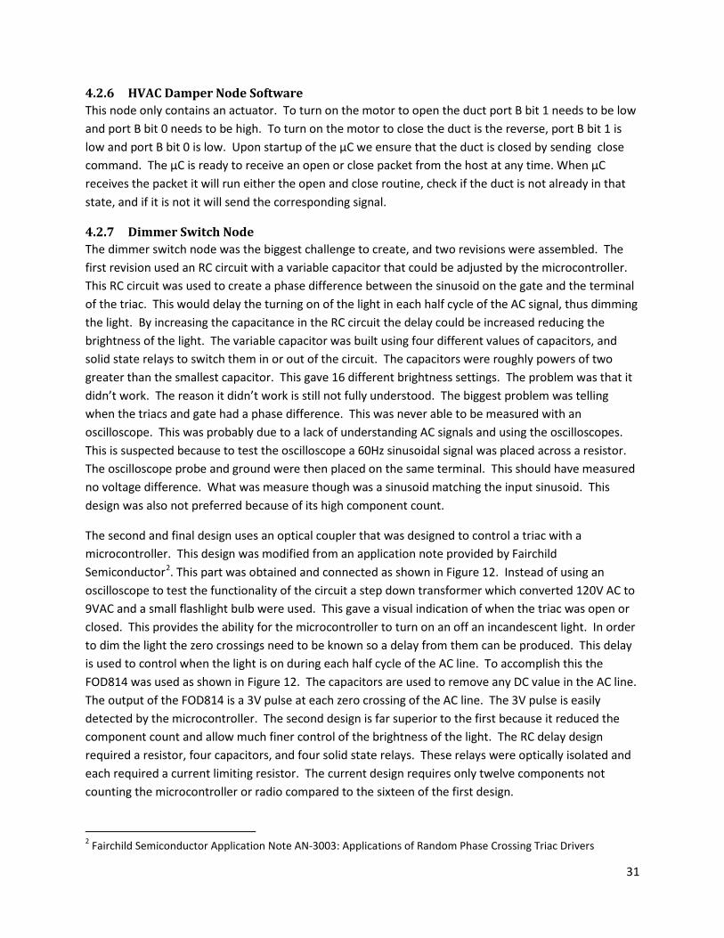
4.2.6 HVAC Damper Node Software This node only contains an actuator. To turn on the motor to open the duct port B bit 1 needs to be low and port B bit 0 needs to be high. To turn on the motor to close the duct is the reverse, port B bit 1 is low and port B bit 0 is low. Upon startup of the µC we ensure that the duct is closed by sending close command. The µC is ready to receive an open or close packet from the host at any time. When µC receives the packet it will run either the open and close routine, check if the duct is not already in that state, and if it is not it will send the corresponding signal.
4.2.7 Dimmer Switch Node The dimmer switch node was the biggest challenge to create, and two revisions were assembled. The first revision used an RC circuit with a variable capacitor that could be adjusted by the microcontroller. This RC circuit was used to create a phase difference between the sinusoid on the gate and the terminal of the triac. This would delay the turning on of the light in each half cycle of the AC signal, thus dimming the light. By increasing the capacitance in the RC circuit the delay could be increased reducing the brightness of the light. The variable capacitor was built using four different values of capacitors, and solid state relays to switch them in or out of the circuit. The capacitors were roughly powers of two greater than the smallest capacitor. This gave 16 different brightness settings. The problem was that it didn’t work. The reason it didn’t work is still not fully understood. The biggest problem was telling when the triacs and gate had a phase difference. This was never able to be measured with an oscilloscope. This was probably due to a lack of understanding AC signals and using the oscilloscopes. This is suspected because to test the oscilloscope a 60Hz sinusoidal signal was placed across a resistor. The oscilloscope probe and ground were then placed on the same terminal. This should have measured no voltage difference. What was measure though was a sinusoid matching the input sinusoid. This design was also not preferred because of its high component count.
The second and final design uses an optical coupler that was designed to control a triac with a microcontroller. This design was modified from an application note provided by Fairchild Semiconductor2. This part was obtained and connected as shown in Figure 12. Instead of using an oscilloscope to test the functionality of the circuit a step down transformer which converted 120V AC to 9VAC and a small flashlight bulb were used. This gave a visual indication of when the triac was open or closed. This provides the ability for the microcontroller to turn on an off an incandescent light. In order to dim the light the zero crossings need to be known so a delay from them can be produced. This delay is used to control when the light is on during each half cycle of the AC line. To accomplish this the FOD814 was used as shown in Figure 12. The capacitors are used to remove any DC value in the AC line. The output of the FOD814 is a 3V pulse at each zero crossing of the AC line. The 3V pulse is easily detected by the microcontroller. The second design is far superior to the first because it reduced the component count and allow much finer control of the brightness of the light. The RC delay design required a resistor, four capacitors, and four solid state relays. These relays were optically isolated and each required a current limiting resistor. The current design requires only twelve components not counting the microcontroller or radio compared to the sixteen of the first design.
2 Fairchild Semiconductor Application Note AN-3003: Applications of Random Phase Crossing Triac Drivers

32
To provide DC power for the electronics an old cell phone charger is used. This charger provides 5V DC from 120VAC. The radios maximum voltage is 3.6V for this reason a voltage regulator is used to convert the 5V DC to 3.3V DC.
The dimmer switch connects to 120 AC outlets. For safety purposes it was decided to place the circuitry inside a plastic box. In addition a switch was placed on the box to provide an additional measure of safety. The plastic box placed space constraights on the design this required that 3 small perf board segments be used to implement the design. To increase the safety of handling and debugging the boards, one board was designated for 120V components; another board was used for low power DC components. The third board was the salvaged cell phone charger.
Figure 11: Completed Dimmer Switch

33
Figure 12: Dimmer Switch Schematic
4.2.8 Dimmer Switch Node Software The amount of power that is delivered to the lamp is controlled by the microcontroller. This allows the host to dictate how much power the lamp. A built in timer and external interrupts are features of the microcontroller that make this possible. To explain the software design approach, first the mechanics of circuit above need to be understood. The lamp turns on when port B outputs a high signal, this only needs to be a pulse and the triac will stay on until current stops flowing though it. For resistive loads the no current flows though the triac at the zero crossing. The lamp turns off only when port B is low and the AC power signal crosses zero. The signal crosses zero at a rate of 120Hz or ever y 8.6 milliseconds. The zero crossings detected by the FOD814 generate a pules which is programmed to cause an external interrupt on pin 4 of the microcontroller.
With the lamp turned of the microcontrollers internal timer was calibrated and found that it counted to 266 in 8.6 milliseconds. When a zero crossing interrupt is fired this timer is started. When the timer finishes a high pulse is given on port B to turn on the lamp. The lamp will stay on until the next zero crossing. The longer it takes before before the pulse is given the smaller the amount of power the lamp receives. The timer is restarted after every zero crossing and pulse given again after the timer counts to the specified value. By adjusting this delay the brightness of the light can be varied. Figure 13 demonstrates the lamp receiving power for 50% of the time. In this scenario the microcontoller counts to 133.
C2
220
R1
3V DC
10K
FOD814
21
43
C2R1
BTA24-800B
XB24-ACI-001
2
1
3
10
Dout
VCC
Din
Gnd
Lamp
1 2
ATmega168
123456789
1011121314 15
16171819202122232425262728
(RESET)RXDTXDPD2PD3PD4VCCGNDPB6PB7PD5PD6PD7PB0 PB1
PB2PB3PB4PB5
AVCCAREFGND
(ADC0)PC0(ADC1)PC1(ADC2)PC2(ADC3)PC3(ADC4)PC4(ADC5)PC5L1
1 2
3V DC
MOC3012M
120Vac C1
3V DC
220

34
Figure 13: Oscilloscope View of the dimmer switch control
4.3 Communication Protocol The communication protocol was altered throughout the implementation of the project as new problems arose. Initially, the host had to send a “Request to Send” character to a node and wait for a “Clear to Send” response before sending a packet. In the end, the host could send a packet at any time and wait for an “Acknowledge” packet to be sent in reply. The “escape” byte was added later to allow for certain characters to be represented in the data bytes without error. The “Event” packet type was also added when it was realized that certain sensors, such as a motion sensor, should trigger an event rather than be sampled at regular intervals.
4.4 Test Results Each component was tested individually by sending packets to the node manually via a terminal. Each node responds correctly to commands sent to it. The host software was tested by writing a windows application in C# to simulate the behavior of a node. This software was able to simulate a node that had an arbitrary number of sensors on it. A large number of sensors were simulated, sending a large amount of data to the host software. The host software performed well and was able to receive and process the data sent to it. The entire system was tested by creating actions via the web interface and seeing if those actions were carried out as expected based on the conditions of sensors. Actions were sent to the actuators very quickly. The system behaves as expected.
5 Scope What has been implemented is only a prototype that demonstrates functionality. The testing performed indicates that each of the features proposed is in working condition but in order to be delivered to a home changes would need to be made to better adapt it. Extensive testing would also be necessary to determine the systems lifetime and stability.
5.1 Lessons Learned In development and debugging a significant amount of time is saved by keeping the code modular. The microcontrollers perform many different tasks and it was necessary that they function independent of another. The Com Protocol is a good example of this. After being tested it is used in many different ways

35
on both the host and the nodes. The use of modularity increases the programs readability for other users attempting to see what actually goes on.
The microcontrollers use some of the functionality of the C library and the printf() function is overloaded to output through the serial port. This was vital in debugging to know what was really going on. This feature alone saved hours of time.
The importance of communication was also a vital lesson learned by developing this system. The system is too large for a single person to implement by themselves. It also has many interdependancies. The actions supported by the host are dependent on those supported by the nodes. Likewise, the software required on each node was dependent on the sensors connected to the microcontroller. In addition the selection of hardware components had a significant impact on the complexity of the software needed on the nodes. With each team member focusing on particular aspects it was essential the needs and capabilities of the individual components be communicated to all members of the team.
5.2 Future Suggestions
5.2.1 Nodes Several improvements to the nodes could be made. These improvements would make the home automation system commercially viable. The improvements include battery life indicators. Each node would also need some sort of indicator of it status. In addition battery life could be extended by utilizing deeper sleep modes of the microcontrollers. In addition sleeping the radio would extend the battery life of each node. This would require a form of synchronized communication between the host and nodes, so that communication to the nodes could be guaranteed. The radios used account for about ½ of the cost of each node. Using a lower cost radio that combines the microcontroller and radio would be required to significantly reduce the cost of the nodes. Further improvements could be made by using smaller microcontrollers on the nodes that do not require the large memory of the Atmege 168V. Further power savings could be obtained by reducing the clock frequency of each node to the minimum required for its application.
Additional nodes could be created to monitor various events. Other nodes could include power usage meters, smoke detectors,keyless entry, and appliance health monitors. Appliance health monitors could be used to monitor the condition of appliances providing notification to the owner when servicing is needed. The system could even be setup to notify the service provider directly.
5.2.2 Host and Web Server There are many features that could be added to the user interface. The ability to export and import system information would be useful. Creating a log of actions performed on actuators would provide the user with a history of things that have happened. The way that sensor data is displayed could be improved. The charts need improvement and the ability to specify a date and time range in which to view the data would be very useful. Having the host software use the API mode of the Xbee radios would allow for additional features, such as the ability to send packets to a specific radio instead of broadcasting them and the ability to detect signal strength of radio transmissions.

36
5.3 System Life-Cycle
5.3.1 Nodes For the nodes to be commercially viable several life-cycle aspects would have to be considered. Mass production of the nodes would drive the cost of each node down significantly. To mass produce the PCB boards would have to be designed for each node. The assembly process of mass production would be simplified though the used of surface mount devices. Most of the devices used on the nodes have input output compatible surface mount equivalents making the schematics used viable. Cases for each node would also need to be designed for each node. The mechanics used to open and close the HVAC damper would also need to be changed from a belt and pulley system to gear driven. Installing a small rubber belt in a duct with many sharp edges is likely to result in many broken belts.
In actual deployment of the system each node would need to be capable of joining a specific network. Battery life would need to be in the range of 2 to 3 years, with notification of low batteries and easy access to the batteries provided on each node. For instance removal of the HVAC damper from the duct should not be required to change its batteries.
5.3.2 Host and Web Server The software would have to be tested more thoroughly before this were deployed as a real system. Writing automated system tests would improve the reliability and maintainability of the software. Performing extensive usability tests on the user interface would provide many insights into how the user interface can be improved.
6 Project Management
6.1 Time Management A gantt chart of time spent on the project is given in the figure below.
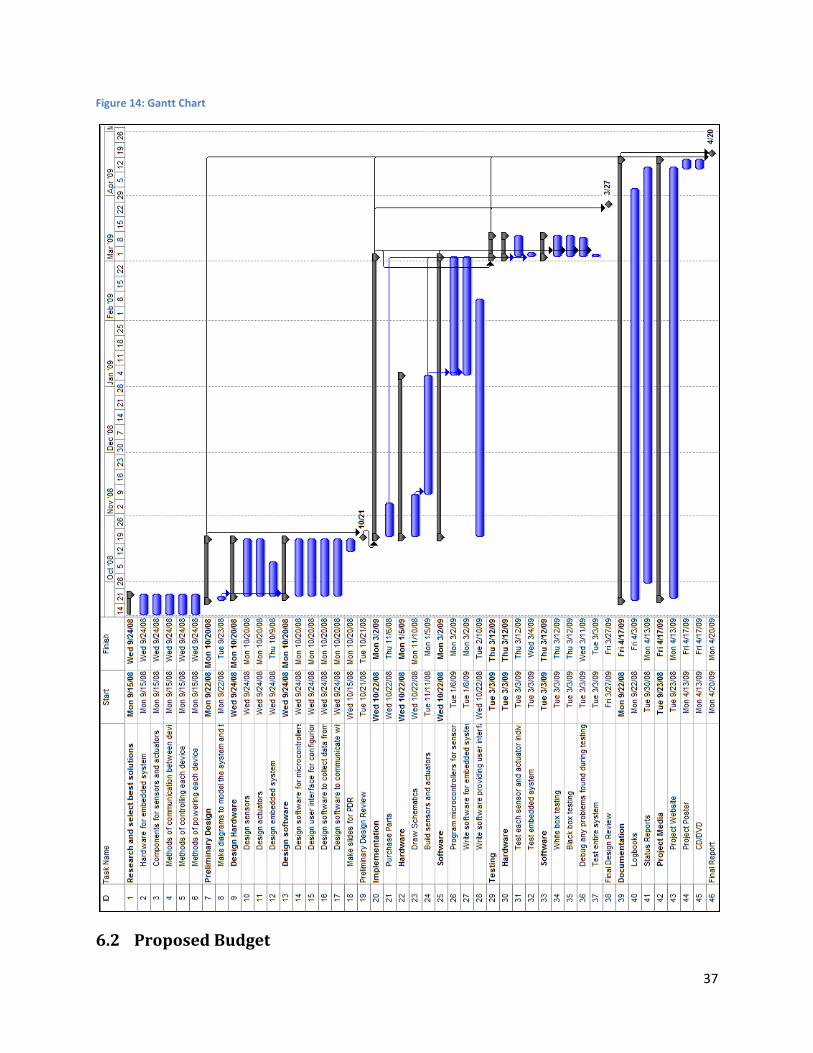
37
Figure 14: Gantt Chart
6.2 Proposed Budget

38
Proposed Budget Part Name Price Quantity Subtotals Compact Flash Card $30.00 1 $30.00 TS-7200 ZigBee Module $99.00 1 $99.00 ZigBee Modules for Sensors/Actuators $30.00 6 $180.00 Motion Sensing Light Switch $20.00 1 $20.00 One Wire Digital Temperature Sensor $4.25 2 $8.50 PIR Motion Sensor $9.95 2 $19.90 Battery Holder $1.95 6 $11.70 Ambient Light Sensor $2.94 2 $5.88 XBee Breakout Board $2.95 6 $17.70 XBee Socket $1.25 6 $7.50 Microcontrollers $5.00 6 $30.00 Miscellaneous Parts $50.00 1 $50.00 TS-7200 Board $150.00 1 $150.00 Tax + Shipping $35.00 Total $665.18 Table 5: Proposed budget
6.3 Final Budget System Cost
Component Description Quantity Unit Price Amount XB24-ACI-001 MaxStream Wireless Modules 5 $19.00 $95.00 STF12PF06 P-Ch 60V 12A Power MOSFET 2 $0.55 $1.10 ATMEGA168V10PU Atmell Atmega 168 Microcontroller 4 $4.11 $16.44 BTA24-800BWRG 25 Amp 800 V Triac 1 $1.73 $1.73 DF3-2428SCC 2.0mm Connectors for radios 25 $0.06 $1.50 CRE22F2FBBNE 20A rocker switch 1 $0.91 $0.91 DF3-10S-2C 10 pin 2.0mm Receptical Housing 5 $0.32 $1.60 FOD814 AC line monitor Optocoupler 1 $0.42 $0.42 MOC3012M Non-Zero Crossing Triac Optocoupler 1 $0.56 $0.56 FQP4N20L N-Ch 200V MOSFET 1 $0.60 $0.60 555-28027 PIR PIR Sensor Module 1 $9.99 $9.99 BH-32 Battery Holder 2 AA 2 $0.75 $1.50 ACS-39 Snap-In AC outlet 1 $0.90 $0.90 LCAC-209 AC Power Cord 1 $0.95 $0.95 1591-CSBK Black Plastic Case 4.7x2.6x1.55 1 $4.40 $4.40 Bh-342 Battery Holder 4 AA 1 $1.00 $1.00 AMS302 Ambient Light Sensor 1 $2.22 $2.22 ASSR-1228-002E 2 Form A Optically Isolated SSR 60V 0.2A 2 $2.10 $4.20
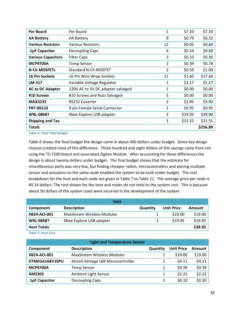
39
Per Board Per Board 1 $7.20 $7.20 AA Battery AA Battery 8 $0.79 $6.32 Various Resistors Various Resistors 12 $0.05 $0.60 .1µF Capacitor Decoupling Caps 6 $0.10 $0.60 Various Capacitors Filter Caps 3 $0.10 $0.30 MCP9700A Temp Sensor 2 $0.39 $0.78 N-Ch MOSFETs Standard N-Ch MOSFET 2 $0.50 $1.00 16 Pin Sockets 16 Pin Wire Wrap Sockets 11 $1.60 $17.60 LM-317 Variable Voltage Regulator 1 $1.17 $1.17 AC to DC Adapter 120V AC to 5V DC adapter salvaged 1 $0.00 $0.00 #10 Screws #10 Screws and Nuts Salvaged 5 $0.00 $0.00 MAX3232 RS232 Coverter 2 $1.95 $3.90 PRT-00110 9 pin Female Serial Connector 1 $0.95 $0.95 WRL-08687 Xbee Explore USB adapter 2 $19.95 $39.90 Shipping and Tax 1 $31.55 $31.55 Totals $256.89 Table 6: Final Total Budget
Table 6 shows the final budget the design came in about 400 dollars under budget. Some key design choices created most of this difference. Three hundred and eight dollars of this savings came from not using the TS-7200 board and associated Zigbee Module. After accounting for these differences the design is about twenty dollars under budget. The final budget shows that the estimate for miscellaneous parts was very low, but finding cheaper radios, microcontrollers and placing multiple sensor and actuators on the same node enabled the system to be built under budget. The cost breakdown for the host and each node are given in Table 7 to Table 11. The average price per node is 40.14 dollars. The cost shown for the host and nodes do not total to the system cost. This is because about 50 dollars of the system costs were incurred in the development of the system.
Host Component Description Quantity Unit Price Amount XB24-ACI-001 MaxStream Wireless Modules 1 $19.00 $19.00 WRL-08687 Xbee Explore USB adapter 1 $19.95 $19.95 Host Totals $38.95 Table 7: Host Cost
Light and Temperature Sensor Component Description Quantity Unit Price Amount XB24-ACI-001 MaxStream Wireless Modules 1 $19.00 $19.00 ATMEGA168V10PU Atmell Atmega 168 Microcontroller 1 $4.11 $4.11 MCP9700A Temp Sensor 1 $0.39 $0.39 AMS302 Ambient Light Sensor 1 $2.22 $2.22 .1µF Capacitor Decoupling Caps 2 $0.10 $0.20
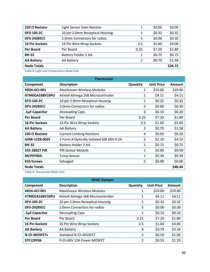
40
220 Ω Resistor Light Sensor Gain Resistor 1 $0.05 $0.05 DF3-10S-2C 10 pin 2.0mm Receptical Housing 1 $0.32 $0.32 DF3-2428SCC 2.0mm Connectors for radios 5 $0.06 $0.30 16 Pin Sockets 16 Pin Wire Wrap Sockets 2.5 $1.60 $4.00 Per Board Per Board 0.25 $7.20 $1.80 BH-32 Battery Holder 2 AA 1 $0.75 $0.75 AA Battery AA Battery 2 $0.79 $1.58 Node Totals $34.72 Table 8: Light and Temperature Node Cost
Thermostat Component Description Quantity Unit Price Amount XB24-ACI-001 MaxStream Wireless Modules 1 $19.00 $19.00 ATMEGA168V10PU Atmell Atmega 168 Microcontroller 1 $4.11 $4.11 DF3-10S-2C 10 pin 2.0mm Receptical Housing 1 $0.32 $0.32 DF3-2428SCC 2.0mm Connectors for radios 5 $0.06 $0.30 .1µF Capacitor Decoupling Caps 2 $0.10 $0.20 Per Board Per Board 0.25 $7.20 $1.80 16 Pin Sockets 16 Pin Wire Wrap Sockets 3.5 $1.60 $5.60 AA Battery AA Battery 2 $0.79 $1.58 220 Ω Resistor Current Limiting Resistors 4 $0.05 $0.20 ASSR-1228-002E 2 Form A Optically Isolated SSR 60V 0.2A 2 $2.10 $4.20 BH-32 Battery Holder 2 AA 1 $0.75 $0.75 555-28027 PIR PIR Sensor Module 1 $9.99 $9.99 MCP9700A Temp Sensor 1 $0.39 $0.39 #10 Screws Salvaged 5 $0.00 $0.00 Node Totals $48.44 Table 9: Thermostat Node Cost
HVAC Damper Component Description Quantity Unit Price Amount XB24-ACI-001 MaxStream Wireless Modules 1 $19.00 $19.00 ATMEGA168V10PU Atmell Atmega 168 Microcontroller 1 $4.11 $4.11 DF3-10S-2C 10 pin 2.0mm Receptical Housing 1 $0.32 $0.32 DF3-2428SCC 2.0mm Connectors for radios 5 $0.06 $0.30 .1µF Capacitor Decoupling Caps 1 $0.10 $0.10 Per Board Per Board 0.25 $7.20 $1.80 16 Pin Sockets 16 Pin Wire Wrap Sockets 2.5 $1.60 $4.00 AA Battery AA Battery 4 $0.79 $3.16 N-Ch MOSFETs Standard N-Ch MOSFET 2 $0.50 $1.00 STF12PF06 P-Ch 60V 12A Power MOSFET 2 $0.55 $1.10

41
FQP4N20L N-Ch 200V MOSFET 1 $0.60 $0.60 DC motor Small DC Motor salvaged from CD-ROM 1 $0.00 $0.00 HVAC Damper Old Damper and components salvaged 1 $0.00 $0.00 Drive Mechanism Drive salvaged from CD-ROM and dowels 1 $0.00 $0.00 Node Totals $35.49 Table 10: 10 HVAC Damper Node Cost
Dimmer Switch Component Description Quantity Unit Price Amount XB24-ACI-001 MaxStream Wireless Modules 1 $19.00 $19.00 ATMEGA168V10PU Atmell Atmega 168 Microcontroller 1 $4.11 $4.11 DF3-10S-2C 10 pin 2.0mm Receptical Housing 2 $0.32 $0.64 DF3-2428SCC 2.0mm Connectors for radios 10 $0.06 $0.60 .1µF Capacitor Decoupling Caps 1 $0.10 $0.10 Per Board Per Board 0.25 $7.20 $1.80 16 Pin Sockets 16 Pin Wire Wrap Sockets 2.5 $1.60 $4.00 AC to DC Adapter 120V AC to 5V DC adapter salvaged 1 $0.00 $0.00 Various Resistors Various Resistors 7 $0.05 $0.35 LM-317 Variable Voltage Regulator 1 $1.17 $1.17 Various Capacitors Filter Caps 3 $0.10 $0.30 ACS-39 Snap-In AC outlet 1 $0.90 $0.90 LCAC-209 AC Power Cord 1 $0.95 $0.95 1591-CSBK Black Plastic Case 4.7x2.6x1.55 1 $4.40 $4.40 BTA24-800BWRG 25 Amp 800 V Triac 1 $1.73 $1.73 CRE22F2FBBNE 20A rocker switch 1 $0.91 $0.91 FOD814 AC line monitor Optocoupler 1 $0.42 $0.42 MOC3012M Non-Zero Crossing Triac Optocoupler 1 $0.56 $0.56 Node Totals $41.94 Table 11: Dimmer Switch Node Cost
6.4 Facilities Utilized To implement the home automation system the labs at Utah State University were used for hardware design and debugging. The labs in the engineering lab building at USU have oscilloscopes, multimeters and signal generators that were used. In addition much of the wire wrapping and soldiering of the nodes was done in Abe’s apartment with his own tools.
6.5 Personnel Contributions Abe Clements was responsible for designing, building and debugging the hardware on the nodes. This involved considerable research to select proper components and sensors. The project involves a large range of hardware from motors, 120V AC interfacing to small signal sensors. This required Abe to gain knowledge of power electronics, motor control, and sensor calibration. In addition there are literally millions of parts which could meet the requirements of the design, but the goal was to create simple
42
easy to program low cost nodes. This goal was achieved with an average cost per node of 40.14. Abe also implemented the com protocol on the microcontrollers used on the nodes. This was done in tight connection with John Snow who implemented the com protocol on the host.
John Snow was responsible for designing and implementing the web server, user interface, and host software. This required the use of PHP, MySQL, and C++. Programming the host software required John to gain knowledge in writing multi-threaded applications for the Linux platform. Serial communication and communication via XML-RPC were additional components to the host software that required research and learning.
Scott Needham was responsible for the microcontroller software and interfacing the sensors. He also assisted in debugging the com protocol and in the communication between the nodes. He set up the programmer and AVR studio to load programs on the microcontroller. He explored the features of the microcontroller and implemented them.
7 Conclusion The project provides a way for a user to collect data from sensors and control actuators based on sensor conditions. The system of sensors and actuators can be used to implement a home automation system. The system can be controlled via a web interface from any device with internet access and a web browser.
If deployed in an actual home, the system could potentially reduce energy consumption in the home if used properly. The system is essentially a prototype of an inexpensive solution to home automation. On a global scale, such a system could be used to reduce energy consumption and costs in businesses and homes. This could have significant economic effects, such as reducing the amount of money that businesses and home owners spend on energy. Socially, the system can change the way that individuals interact with, control, and monitor their homes.

43
Appendix A: Code for Host Software
Action.cpp /* * Action.cpp * */ #include "Action.h" using namespace std; map<int, Action> ActionList; Action::Action(int newID, bool rpt) { // TODO Auto-generated constructor stub triggered = false; id = newID; repeat = rpt; sendEmail = false; } Action::Action() { triggered = false; sendEmail = false; } void Action::Trigger() { bool conditions_met = CheckConditions(); if ((repeat == true || (repeat == false && triggered == false)) && conditions_met) { cout << "\n\n\n\nACTION TRIGGERED!\t #" << id << "\n\n\n"; for ( it=packetList.begin() ; it != packetList.end(); it++ ) { queuePacket((*it)); //(*it).print(); } if (sendEmail) { xmlrpc_send_email(email_message); } triggered = true; } else if (repeat == false && triggered == true && !conditions_met) { triggered = false; } } bool Action::CheckConditions() { bool conditionsMet = true; for ( conditionsIterator=sensorConditions.begin() ; conditionsIterator != sensorConditions.end(); conditionsIterator++ ) { conditionsMet &= (*conditionsIterator).second; } return conditionsMet; } void Action::AddCondition(string new_condition_id) { sensorConditions[new_condition_id] = false; } void Action::AddPacket(Packet pkt) { cout << "Adding packet to action.\n"; packetList.push_back(pkt); } bool AddAction(Action act) { if (ActionList.count(act.id) == 0) { ActionList[act.id] = act; return true; } return false;
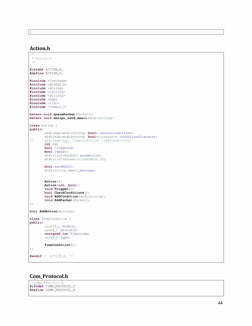
44
}
Action.h /* * Action.h */ #ifndef ACTION_H_ #define ACTION_H_ #include <iostream> #include <stdint.h> #include <string> #include <cstring> #include <utility> #include <map> #include <list> #include "common.h" extern void queuePacket(Packet); extern void xmlrpc_send_email(std::string); class Action { public: std::map<std::string, bool> sensorConditions; std::map<std::string, bool>::iterator conditionsIterator; // std::map<int, TimeCondition> timeConditions; int id; bool triggered; bool repeat; std::list<Packet> packetList; std::list<Packet>::iterator it; bool sendEmail; std::string email_message; Action(); Action(int, bool); void Trigger(); bool CheckConditions(); void AddCondition(std::string); void AddPacket(Packet); }; bool AddAction(Action); class TimeCondition { public: uint16_t NodeID; uint8_t DeviceID; unsigned int Timestamp; uint8_t Type; TimeCondition(); }; #endif /* ACTION_H_ */
Com_Protocol.h //Comm Protocol.h #ifndef COMM_PROTOCOL_H #define COMM_PROTOCOL_H
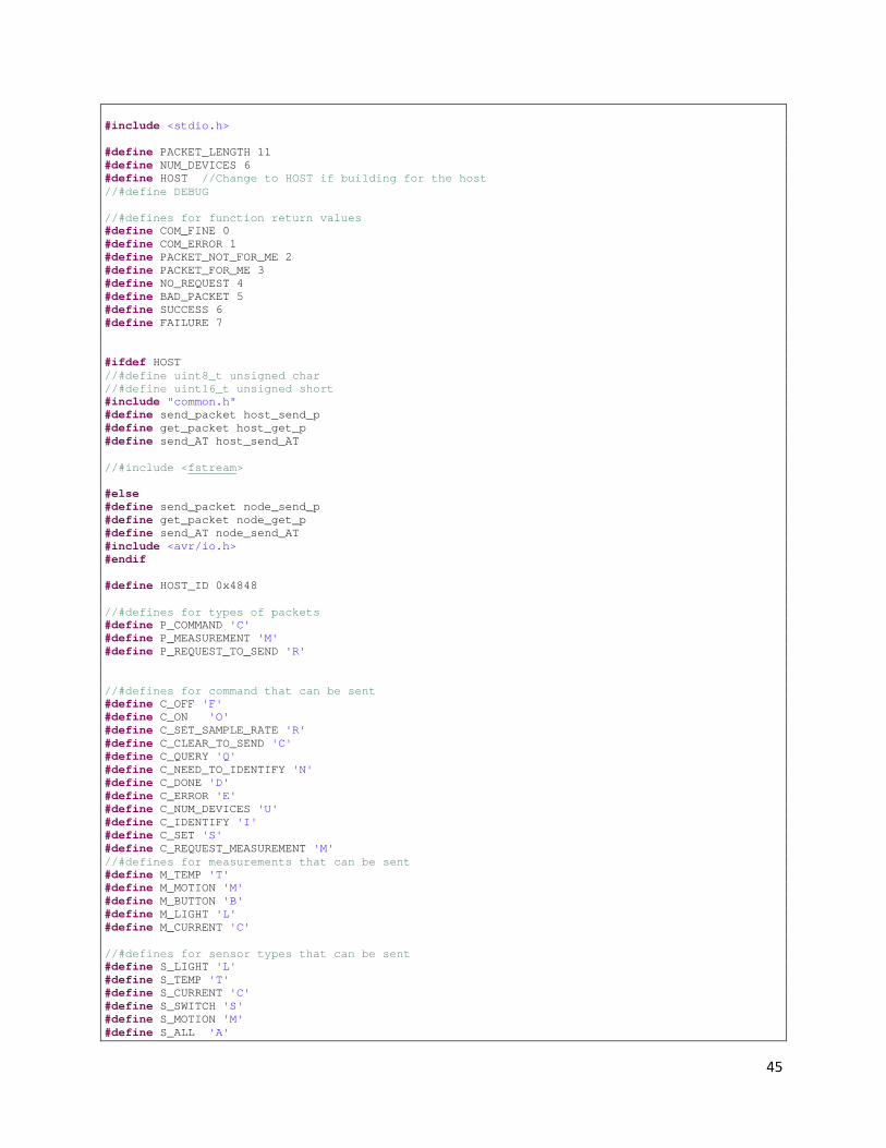
45
#include <stdio.h> #define PACKET_LENGTH 11 #define NUM_DEVICES 6 #define HOST //Change to HOST if building for the host //#define DEBUG //#defines for function return values #define COM_FINE 0 #define COM_ERROR 1 #define PACKET_NOT_FOR_ME 2 #define PACKET_FOR_ME 3 #define NO_REQUEST 4 #define BAD_PACKET 5 #define SUCCESS 6 #define FAILURE 7 #ifdef HOST //#define uint8_t unsigned char //#define uint16_t unsigned short #include "common.h" #define send_packet host_send_p #define get_packet host_get_p #define send_AT host_send_AT //#include <fstream> #else #define send_packet node_send_p #define get_packet node_get_p #define send_AT node_send_AT #include <avr/io.h> #endif #define HOST_ID 0x4848 //#defines for types of packets #define P_COMMAND 'C' #define P_MEASUREMENT 'M' #define P_REQUEST_TO_SEND 'R' //#defines for command that can be sent #define C_OFF 'F' #define C_ON 'O' #define C_SET_SAMPLE_RATE 'R' #define C_CLEAR_TO_SEND 'C' #define C_QUERY 'Q' #define C_NEED_TO_IDENTIFY 'N' #define C_DONE 'D' #define C_ERROR 'E' #define C_NUM_DEVICES 'U' #define C_IDENTIFY 'I' #define C_SET 'S' #define C_REQUEST_MEASUREMENT 'M' //#defines for measurements that can be sent #define M_TEMP 'T' #define M_MOTION 'M' #define M_BUTTON 'B' #define M_LIGHT 'L' #define M_CURRENT 'C' //#defines for sensor types that can be sent #define S_LIGHT 'L' #define S_TEMP 'T' #define S_CURRENT 'C' #define S_SWITCH 'S' #define S_MOTION 'M' #define S_ALL 'A'

46
//#defines for actuator types that can be sent #define A_VAR_SWITCH 'V' #define A_DUCT 'D' #define A_SWITCH 'S' #define A_EMAIL 'E' #define A_ALL 'A' #define DEFAULT_DATA 0x4444 typedef struct com_packet_ { uint8_t Id; uint8_t Type; uint8_t Device; uint16_t Data; uint16_t Dest; uint16_t Source; }com_packet; typedef struct node_info_ { uint16_t NodeId; uint16_t NumDevices; uint8_t DeviceType[NUM_DEVICES]; uint8_t SorA[NUM_DEVICES]; }node_info; uint8_t init_node(uint16_t,uint16_t,uint8_t*,uint8_t*); void send_packet(com_packet *); uint8_t check_for_request(com_packet *); void send_command(uint8_t,uint8_t,uint16_t,uint16_t); void send_measurement(uint8_t, uint8_t, uint16_t, uint16_t); void identify(); uint8_t node_get_packet(com_packet *); unsigned int host_get_p(com_packet *); void node_send_p(com_packet * ); uint8_t node_get_p(com_packet *); void get_node_info(node_info * ); uint8_t set_radio_source(uint16_t NodeID); int set_radio_dest(uint16_t DestID); uint8_t node_send_AT(uint8_t * Com,uint8_t length); int host_send_AT(char * Com, int length); #ifdef HOST void init_host(int); void RTS(uint16_t); void host_send_p(com_packet * ); unsigned int string_to_packet(com_packet *, char *); #endif #endif
Common.h /* * common.h * * Created on: Feb 24, 2009 * Author: jtsnow */ #ifndef COMMON_H_ #define COMMON_H_ #include <iostream> #include <fstream> #include <cstdlib>
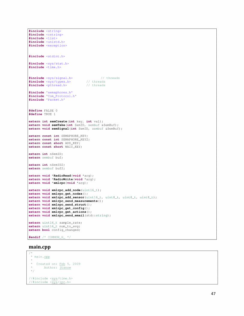
47
#include <string> #include <cstring> #include <list> #include <unistd.h> #include <exception> #include <stdint.h> #include <sys/stat.h> #include <time.h> #include <sys/signal.h> // threads #include <sys/types.h> // threads #include <pthread.h> // threads #include "semaphores.h" #include "Com_Protocol.h" #include "Packet.h" #define FALSE 0 #define TRUE 1 extern int semCreate(int key, int val); extern void semTake(int SemID, sembuf &SemBuf); extern void semSignal(int SemID, sembuf &SemBuf); extern const int SEMAPHORE_KEY; extern const int SEMAPHORE_KEY2; extern const short ADD_KEY; extern const short WAIT_KEY; extern int nSemID; extern sembuf buf; extern int nSemID2; extern sembuf buf2; extern void *RadioRead(void *arg); extern void *RadioWrite(void *arg); extern void *xmlrpc(void *arg); extern void xmlrpc_add_node(uint16_t); extern void xmlrpc_get_nodes(); extern void xmlrpc_add_sensor(uint16_t, uint8_t, uint8_t, uint8_t); extern void xmlrpc_send_measurements(); extern void xmlrpc_send_struct(); extern void xmlrpc_get_config(); extern void xmlrpc_get_actions(); extern void xmlrpc_send_email(std::string); extern uint16_t sample_rate; extern uint16_t num_to_avg; extern bool config_changed; #endif /* COMMON_H_ */
main.cpp /* * main.cpp * * Created on: Feb 5, 2009 * Author: jtsnow */ //#include <sys/time.h> //#include <sys/ipc.h>
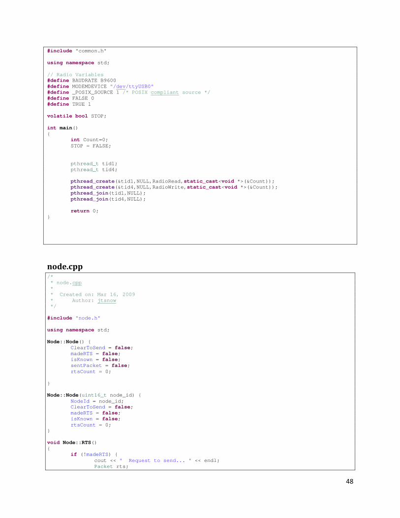
48
#include "common.h" using namespace std; // Radio Variables #define BAUDRATE B9600 #define MODEMDEVICE "/dev/ttyUSB0" #define _POSIX_SOURCE 1 /* POSIX compliant source */ #define FALSE 0 #define TRUE 1 volatile bool STOP; int main() { int Count=0; STOP = FALSE; pthread_t tid1; pthread_t tid4; pthread_create(&tid1,NULL,RadioRead,static_cast<void *>(&Count)); pthread_create(&tid4,NULL,RadioWrite,static_cast<void *>(&Count)); pthread_join(tid1,NULL); pthread_join(tid4,NULL); return 0; }
node.cpp /* * node.cpp * * Created on: Mar 16, 2009 * Author: jtsnow */ #include "node.h" using namespace std; Node::Node() { ClearToSend = false; madeRTS = false; isKnown = false; sentPacket = false; rtsCount = 0; } Node::Node(uint16_t node_id) { NodeId = node_id; ClearToSend = false; madeRTS = false; isKnown = false; rtsCount = 0; } void Node::RTS() { if (!madeRTS) { cout << " Request to send... " << endl; Packet rts;

49
rts = NodeId; rts.send(); } } Node::Device::Device() { } Node::Device::Device(uint8_t newID, uint8_t newType, uint8_t newClass) { id = newID; Type = newType; Class = newClass; sprintf(idString, "%d",id); sprintf(TypeString, "%c", Type); sprintf(ClassString, "%c", Class); average = 0; total = 0; sampleCount = 0; LastSample = 0; } void Node::Device::CheckConditions() { for ( it=Conditions.begin() ; it != Conditions.end(); it++ ) { //if ((*it).second.Check(LastSample)) { //cout << "\n\t\tCondition " << (*it).second.id << " fired!!\n\n"; //} (*it).second.Check(LastSample); } } void Node::Device::AddCondition(SensorCondition condition) { cout << "Adding condition to device #" << idString << "\t Op: " << condition.Operator << " Value: " << condition.Value << endl; Conditions[condition.id] = condition; } void Node::sendPackets() { Packet toSend; if (sentPacket && (rtsTimer.elapsed() > (float)(rand() % 6 + 8))) { sentPacket = false; cout << "Sending packet timed out." << endl; } //if (ClearToSend) { if (!sentPacket && !TxQueue[NodeId].empty()) { //Node::RTS(); //usleep(1000); toSend = TxQueue[NodeId].front(); //cout << " Sending from outbox... "; //toSend.print(); if (toSend.send()) { //cout << "Sent.\n"; //Outbox.pop_front(); sentPacket = true; rtsTimer.start(); } } } void Node::addPacket(Packet pkt) { if (pkt.Type == P_MEASUREMENT && isKnown) { // Handle measurement //list<Packet>::iterator it; //int average = 0;
50
if (pkt.Data <= 1023) { Device currentDevice = Devices[pkt.Device]; cout << "Adding measurement to sensor... Device: " << Devices[pkt.Device].idString << " \tType:" << Devices[pkt.Device].TypeString << endl; //Devices[pkt.Device].Samples.push_back(pkt); cout << "Collected " << currentDevice.sampleCount << " samples." << endl; currentDevice.total += pkt.Data; currentDevice.LastSample = pkt.Data; currentDevice.sampleCount++; currentDevice.CheckConditions(); if (currentDevice.sampleCount >= num_to_avg && currentDevice.sampleCount > 0) { currentDevice.average = currentDevice.total / currentDevice.sampleCount; pkt.Data = static_cast<uint16_t>(currentDevice.average); cout << "\t Sample Average: \t " << pkt.Data << endl; Measurements.push_back(pkt); currentDevice.sampleCount = 0; currentDevice.total = 0; } Devices[pkt.Device] = currentDevice; } else if (pkt.Data > 1023) { cout << "\n\nData is too big!!! Data: " << pkt.Data << "\n\n"; } } else if (pkt.Type == 'E' && isKnown) { // Handle Event Device currentDevice = Devices[pkt.Device]; cout << "Event detected... Device: " << Devices[pkt.Device].idString << " \tType:" << Devices[pkt.Device].TypeString << endl; currentDevice.durationTimer.start(); currentDevice.LastSample = 1; currentDevice.sampleCount++; currentDevice.CheckConditions(); Devices[pkt.Device] = currentDevice; } else if (pkt.Type == P_COMMAND && pkt.Id == C_NEED_TO_IDENTIFY) { // Handle need to identify } else if (pkt.Type == P_COMMAND && pkt.Id == C_IDENTIFY) { // Handle identify Device newDevice(pkt.Device, static_cast<uint8_t>(pkt.Data), static_cast<uint8_t>(pkt.Data>>8)); Devices[pkt.Device] = newDevice; if (newDevice.Type == 'M') { EventBasedDevices.push_back(pkt.Device); } cout << "Device[" << Devices[pkt.Device].idString << "] Identified: " << Devices[pkt.Device].TypeString << " " << Devices[pkt.Device].ClassString << endl; xmlrpc_add_sensor(NodeId, newDevice.id, newDevice.Class, newDevice.Type); if (!isKnown) { isKnown = true; SetSampleRate(); } } else if (pkt.Type == P_COMMAND && pkt.Id == C_ERROR) { // Handle error
51
} else if (sentPacket && pkt.Type == P_COMMAND && pkt.Id == 'A') { cout << "Acknowledge received" << endl; TxQueue[NodeId].pop_front(); sentPacket = false; rtsTimer.stop(); } } void Node::AddDevice(uint8_t newID, uint8_t newType, uint8_t newClass) { Device newDevice(newID, newType, newClass); Devices[newID] = newDevice; if (newDevice.Type == 'M') { EventBasedDevices.push_back(newID); } cout << "Device[" << Devices[newID].idString << "] Added: " << Devices[newID].TypeString << " " << Devices[newID].ClassString << endl; } void Node::ClearConditions() { for ( DevicesIterator=Devices.begin() ; DevicesIterator != Devices.end(); DevicesIterator++ ) { ((*DevicesIterator).second).Conditions.clear(); } } void Node::eventTimeout() { for ( EBDiterator=EventBasedDevices.begin() ; EBDiterator != EventBasedDevices.end(); EBDiterator++ ) { Device currentDevice = Devices[*EBDiterator]; if (currentDevice.durationTimer.elapsed() > 60.0) { cout << "Event timeout... Device: " << Devices[currentDevice.id].idString << " \tType:" << Devices[currentDevice.id].TypeString << endl; currentDevice.durationTimer.stop(); currentDevice.LastSample = 0; currentDevice.sampleCount = 0; currentDevice.CheckConditions(); Devices[currentDevice.id] = currentDevice; } else { Packet packet; packet.Set(M_MOTION, 'E', currentDevice.id, DEFAULT_DATA, 0xFF01); packet.Source = NodeId; Measurements.push_back(packet); } } } void Node::Query() { Packet packet; packet.Set(C_QUERY, P_COMMAND, '0', DEFAULT_DATA, NodeId); TxQueue[NodeId].push_back(packet); } void Node::sendPacket(Packet pkt) { cout << "Adding packet to outbox...\n"; TxQueue[NodeId].push_back(pkt); } void Node::requestMeasurement() { Packet packet; packet.Set(C_REQUEST_MEASUREMENT, P_COMMAND, '0', DEFAULT_DATA, NodeId); TxQueue[NodeId].push_back(packet); } void Node::SetSampleRate() { Packet packet;

52
packet.Set(C_SET_SAMPLE_RATE, P_COMMAND, '0', sample_rate, NodeId); cout << "\t\tAdding SetSampleRate to Outbox!\n"; TxQueue[NodeId].push_back(packet); } void Node::On() { } void Node::Off() { } void Node::Done() { } void Node::Increase() { } void Node::Decrease() { } void Node::SetValue() { } bool SensorCondition::Check(uint16_t currentValue) { bool result = false; switch(Operator) { case 'g': result = (currentValue > Value); break; case 'l': result = (currentValue < Value); break; case 'e': result = (currentValue == Value); break; default: result = false; } ActionList[actionID].sensorConditions[id] = result; ActionList[actionID].Trigger(); return result; } SensorCondition::SensorCondition() { } SensorCondition::SensorCondition(string newID, int newActionID, uint16_t newValue, uint8_t newOperator) { id = newID; actionID = newActionID; Value = newValue; Operator = newOperator; }
node.h /* * node.h * * Created on: Mar 16, 2009 * Author: jtsnow */ #ifndef NODE_H_ #define NODE_H_ #include <iostream> #include <stdint.h> #include <string> #include <cstring> #include <map> #include <list> #include "common.h" #include "Timer.h" #include "Action.h" extern bool transmit(std::string); extern void queuePacket(Packet);

53
extern std::list<Packet> Measurements; extern std::map<int, Action> ActionList; extern std::map<uint16_t, std::list<Packet> > TxQueue; class SensorCondition { public: std::string id; int actionID; uint16_t node_id; uint8_t device_id; uint16_t Value; uint8_t Operator; SensorCondition(); SensorCondition(std::string, int, uint16_t, uint8_t); bool Check(uint16_t); }; class Node { public: class Device { public: Device(); Device(uint8_t, uint8_t, uint8_t); uint8_t id; uint8_t Type; uint8_t Class; uint16_t LastSample; unsigned int average; unsigned int sampleCount; unsigned int total; char idString[5]; char TypeString[7]; char ClassString[7]; Timer durationTimer; std::map<std::string, SensorCondition>::iterator it; std::map<std::string, SensorCondition> Conditions; void CheckConditions(); void AddCondition(SensorCondition); }; uint16_t NodeId; std::string NodeIdString; uint16_t NumDevices; uint8_t DeviceType[NUM_DEVICES]; uint8_t SorA[NUM_DEVICES]; std::map<uint8_t, Device> Devices; std::map<uint8_t, Device>::iterator DevicesIterator; std::list<uint8_t> EventBasedDevices; std::list<uint8_t>::iterator EBDiterator; bool isKnown; bool madeRTS; bool ClearToSend; bool sentPacket; int rtsCount; Timer rtsTimer; Node(); Node(uint16_t); void sendPackets(); void requestMeasurement(); void addPacket(Packet);

54
void sendPacket(Packet); void AddDevice(uint8_t, uint8_t, uint8_t); void eventTimeout(); void ClearConditions(); void On(); void Off(); void SetSampleRate(); void Query(); void Done(); void Increase(); void Decrease(); void SetValue(); void RTS(); }; #endif /* NODE_H_ */
NodeList.cpp /* * NodeList.cpp */ #include "NodeList.h" using namespace std; NodeList::NodeList() { // TODO Auto-generated constructor stub } bool NodeList::AddNode(Node newNode) { if (Nodes.count(newNode.NodeId)) { return false; } newNode.Query(); //Nodes.insert ( pair<uint16_t, Node>(newNode.NodeId, newNode) ); Nodes[newNode.NodeId] = newNode; cout << "Adding new node to node list: " << newNode.NodeId << endl; if (!newNode.isKnown) { xmlrpc_add_node(newNode.NodeId); } return true; } void NodeList::AddPacket(Packet newPacket) { Node tempNode; cout << "Adding packet to node...\n"; if (Nodes.count(newPacket.Source) > 0) { tempNode = Nodes[newPacket.Source]; tempNode.addPacket(newPacket); Nodes[newPacket.Source] = tempNode; cout << "Added packet to Node #" << tempNode.NodeId << endl; } else { //tempNode = new Node(newPacket.Source); tempNode.NodeId = newPacket.Source; tempNode.addPacket(newPacket); NodeList::AddNode(tempNode); } } void NodeList::AddNode(int newNodeID) { Node tempNode; cout << "Adding node to list...\n";

55
tempNode.NodeId = (uint16_t)newNodeID; tempNode.isKnown = true; NodeList::AddNode(tempNode); } int NodeList::Count() { return (int)Nodes.size(); } bool NodeList::Exists(uint16_t id) { if (Nodes.count(id) > 0) return true; else return false; } void NodeList::sendPackets() { for ( it=Nodes.begin() ; it != Nodes.end(); it++ ) { (*it).second.sendPackets(); usleep(100000); } } void NodeList::SetSampleRate() { for ( it=Nodes.begin() ; it != Nodes.end(); it++ ) { (*it).second.SetSampleRate(); } } void NodeList::eventDaemon() { for ( it=Nodes.begin() ; it != Nodes.end(); it++ ) { (*it).second.eventTimeout(); } } void NodeList::ClearConditions() { for ( it=Nodes.begin() ; it != Nodes.end(); it++ ) { (*it).second.ClearConditions(); } } Node & NodeList::operator[](uint16_t id) { //if (Nodes.count(id)) { return Nodes[id]; //} //return NULL; }
NodeList.h /* * NodeList.h */ #ifndef NODELIST_H_ #define NODELIST_H_ #include <iostream> #include <stdint.h> #include <string> #include <cstring> #include <utility> #include <map> #include <list> #include "common.h" #include "node.h" class NodeList {
56
public: std::map<uint16_t, Node> Nodes; std::map<uint16_t, Node>::iterator it; NodeList(); //void AddNode(uint16_t); bool AddNode(Node); void AddNode(int); void AddPacket(Packet); int Count(); bool Exists(uint16_t); void sendPackets(); void SetSampleRate(); void eventDaemon(); void ClearConditions(); Node & operator[](uint16_t); }; #endif /* NODELIST_H_ */
Packet.cpp /* * Packet.cpp */ #include "Packet.h" extern bool enter_command_mode(); extern bool exit_command_mode(); extern bool send_AT_command(std::string); extern bool transmit(std::string); static uint16_t previous_dest; using namespace std; Packet::Packet() { packetString = ""; return; } void Packet::Set(uint8_t newID, uint8_t newType, uint8_t newDevice, uint16_t newData, uint16_t newDest) { time(×tamp); timestamp -= 25200; Id = newID; Type = newType; Device = newDevice; Data = newData; Dest = newDest; Source = HOST_ID; Packet::encode(); } Packet::Packet(uint8_t newID, uint8_t newType, uint8_t newDevice, uint16_t newData, uint16_t newDest) { time(×tamp); timestamp -= 25200; Id = newID; Type = newType; Device = newDevice; Data = newData; Dest = newDest; Source = HOST_ID; Packet::encode();

57
} Packet::Packet(std::string pkt) { time(×tamp); timestamp -= 25200; packetString = pkt; size = packetString.size(); Packet::decode(); } Packet& Packet::operator=(std::string pkt) { this->packetString = pkt; time(×tamp); timestamp -= 25200; size = packetString.size(); this->decode(); return *this; } Packet& Packet::operator=(char *pkt) { this->packetString.clear(); this->packetString = pkt; time(×tamp); timestamp -= 25200; size = packetString.size(); this->decode(); return *this; } Packet& Packet::operator=(char c) { this->packetString = c; time(×tamp); timestamp -= 25200; size = packetString.size(); this->decode(); return *this; } void Packet::decode() { Type = size > 0 ? packetString[0] : 0; Id = size > 1 ? packetString[1] : 0; Device = size > 2 ? packetString[2] : 0; Special = size > 3 ? packetString[3] : 0; Data = size > 5 ? packetString[4]<<8|(packetString[5] & 0x00FF) : 0; Dest = size > 7 ? packetString[6]<<8|(packetString[7] & 0x00FF) : 0; Source = size > 9 ? packetString[8]<<8|(packetString[9] & 0x00FF) : 0; //printf("DECODE Data:\t0x%X\n", Data); if (size >= 10) { packetString[PACKET_LENGTH-1] = 0x0D; packetString.erase(PACKET_LENGTH, -1); size = packetString.size(); } else { packetString[size] = 0x0D; } if ((Special & 0x80) != 0) { Data &= 0x00FF; } else if ((Special & 0x40) != 0) { Data &= 0x0DFF; } if ((Special & 0x20) != 0) { Data &= 0xFF00; } else if ((Special & 0x10) != 0) { Data &= 0xFF0D;
58
} } void Packet::encode() { char SendBuf[PACKET_LENGTH]; Special = 0x0F; sprintf(SendBuf,"%c%c%c%c%c%c%c%c%c%c%c%c", Type, Id, Device, Special, (Data>>8)|0x00, Data|0x00, (Dest>>8)|0x00, Dest|0x00, (Source>>8)|0x00, Source|0x00, 0x0D, 0x00); if ((Data>>8) == 0) { SendBuf[4] = 0xFF; Special |= 0x80; } else if ((Data>>8) == 0x0D) { SendBuf[4] = 0xFF; Special |= 0x40; } if ((Data & 0x000F) == 0) { SendBuf[5] = 0xFF; Special |= 0x20; } else if ((Data & 0x0F) == 0x0D) { SendBuf[5] = 0xFF; Special |= 0x10; } SendBuf[3] = Special; packetString = SendBuf; deviceNum = Device; } bool Packet::CheckValid() { return (Dest == 0xFF01 && (Type =='M' || Type == 'C' || Type == 'E')); } void Packet::print() { cout << "Packet: " << packetString << endl; printf("Type:\t0x%X\t%c\n", Type, packetString[0]); printf("ID:\t0x%X\t%c\n", Id, packetString[1]); printf("Device:\t0x%X\t%c\n", Device, packetString[2]); printf("Spec:\t0x%X\t%c\n", Special, packetString[3]); printf("Data:\t0x%X\t%c%c\n", Data, packetString[4], packetString[5]); printf("Dest:\t0x%X\t%c%c\n", Dest, packetString[6], packetString[7]); printf("Source:\t0x%X\t%c%c\n", Source, packetString[8], packetString[9]); } bool Packet::send() { if (packetString.size() < 1) { cout << "Error in Packet::send(): Packet string has length < 1." << endl; return false; } cout << "\nSending Packet: " << endl;

59
print(); cout << endl << endl; cout << "Sending Packet: " << packetString << endl; return transmit(packetString); } bool Packet::changeDestination() { bool success = true; success = success && enter_command_mode(); success = success && send_AT_command("ATDL0000"); success = success && send_AT_command("ATAC"); success = success && exit_command_mode(); if (success) { previous_dest=Dest; } return success; } void Packet::set_time() { time(×tamp); timestamp -= 25200; }
Packet.h /* * Packet.h */ #ifndef PACKET_H_ #define PACKET_H_ #include <iostream> #include <stdint.h> #include <string> #include <cstring> #include "Com_Protocol.h" class Packet { public: std::string packetString; time_t timestamp; uint8_t Id; uint8_t Type; uint8_t Device; uint8_t Special; uint16_t Data; uint16_t Dest; uint16_t Source; uint8_t DataHigh; uint8_t DataLow; int deviceNum; int size; Packet(); Packet(std::string); Packet(uint8_t, uint8_t, uint8_t, uint16_t, uint16_t); void set_time(); void decode(); void encode();

60
bool CheckValid(); void print(); void Set(uint8_t, uint8_t, uint8_t, uint16_t, uint16_t); bool send(); bool changeDestination(); //Packet & operator=(const Packet &); Packet &operator = (std::string); Packet &operator = (char *); Packet &operator = (char); private: }; #endif /* PACKET_H_ */
Radio.cpp /* * radio.cpp * * Created on: Feb 24, 2009 * Author: jtsnow */ #include "radio.h" #include "common.h" #include "semaphores.h" #include "Timer.h" #include "node.h" #include "NodeList.h" using namespace std; extern volatile bool STOP; extern std::list<Packet> Measurements; int wait_flag=TRUE; /* TRUE while no signal received */ bool command_mode = FALSE; bool mode_switch = FALSE; int FileDescriptor; list<string> Received; map<uint16_t, list<Packet> > TxQueue; //list<Packet> ReceivedList; list<string> CommandResponses; int CRSemID; sembuf CRbuf; int CMSemID; sembuf CMbuf; int inputSemID; sembuf inputSemBuf; Timer CommandModeTimer; NodeList Nodes; void *RadioRead(void *arg) { //char AT_buffer[10]; char buffer[255]; string tempString; int *Count=static_cast<int *>(arg); //com_packet packet; Count++; Packet LastPacket; int fd, n;
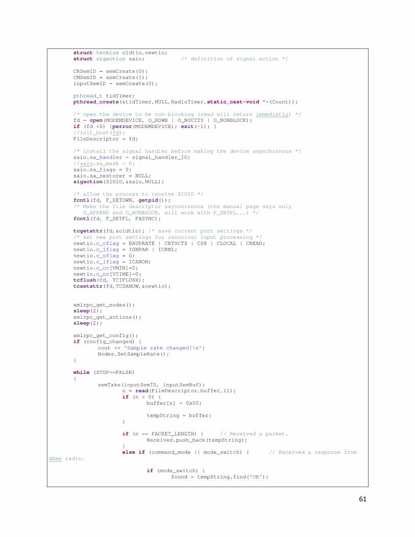
61
struct termios oldtio,newtio; struct sigaction saio; /* definition of signal action */ CRSemID = semCreate(0); CMSemID = semCreate(1); inputSemID = semCreate(0); pthread_t tidTimer; pthread_create(&tidTimer,NULL,RadioTimer,static_cast<void *>(Count)); /* open the device to be non-blocking (read will return immediatly) */ fd = open(MODEMDEVICE, O_RDWR | O_NOCTTY | O_NONBLOCK); if (fd <0) {perror(MODEMDEVICE); exit(-1); } //init_host(fd); FileDescriptor = fd; /* install the signal handler before making the device asynchronous */ saio.sa_handler = signal_handler_IO; //saio.sa_mask = 0; saio.sa_flags = 0; saio.sa_restorer = NULL; sigaction(SIGIO,&saio,NULL); /* allow the process to receive SIGIO */ fcntl(fd, F_SETOWN, getpid()); /* Make the file descriptor asynchronous (the manual page says only O_APPEND and O_NONBLOCK, will work with F_SETFL...) */ fcntl(fd, F_SETFL, FASYNC); tcgetattr(fd,&oldtio); /* save current port settings */ /* set new port settings for canonical input processing */ newtio.c_cflag = BAUDRATE | CRTSCTS | CS8 | CLOCAL | CREAD; newtio.c_iflag = IGNPAR | ICRNL; newtio.c_oflag = 0; newtio.c_lflag = ICANON; newtio.c_cc[VMIN]=0; newtio.c_cc[VTIME]=0; tcflush(fd, TCIFLUSH); tcsetattr(fd,TCSANOW,&newtio); xmlrpc_get_nodes(); sleep(2); xmlrpc_get_actions(); sleep(2); xmlrpc_get_config(); if (config_changed) { cout << "Sample rate changed!\n"; Nodes.SetSampleRate(); } while (STOP==FALSE) { semTake(inputSemID, inputSemBuf); n = read(FileDescriptor,buffer,11); if (n > 0) { buffer[n] = 0x00; tempString = buffer; } if (n == PACKET_LENGTH) { // Received a packet. Received.push_back(tempString); } else if (command_mode || mode_switch) { // Received a response from Xbee radio. if (mode_switch) { found = tempString.find("OK");

62
if (found != string::npos) { mode_switch = false; tempString = "OK"; CommandResponses.push_back(tempString); // Add to response queue. } } else { CommandResponses.push_back(tempString); // Add to response queue. } semSignal(CRSemID, CRbuf); // Signal Rx thread to continue. } else if (n == 9 && tempString.compare(0, 8, "shutdown") == 0) STOP=TRUE; /* stop loop */ } /* restore old port settings */ tcsetattr(fd,TCSANOW,&oldtio); printf("\n DIED! \n"); //pthread_join(tidTimer,NULL); pthread_exit(0); } void *RadioWrite(void *arg) { int *Count=static_cast<int *>(arg); Count++; //char buffer[PACKET_LENGTH]; //com_packet packet; Packet LastPacket; Timer configTimer; Timer daemonTimer; sample_rate = 10; num_to_avg = 20; config_changed = false; srand ( time(NULL) ); sleep(6); string temp; configTimer.start(); daemonTimer.start(); while (STOP==FALSE) { if (Received.size() > 0) { LastPacket = Received.front(); temp = Received.front(); if (LastPacket.CheckValid()) { //printf("Raw Data:\t0x%X %X\t%c%c\n", (int)temp[4], (int)temp[5], temp[4], temp[5]); cout << "\nReceived Packet: " << LastPacket.packetString << endl; LastPacket.print(); Nodes.AddPacket(LastPacket); } else { cout << "\nReceived invalid packet.\n"; } Received.pop_front(); } if (configTimer.elapsed() > 60) { xmlrpc_get_config();

63
if (config_changed) { cout << "Sample rate changed!\n"; Nodes.SetSampleRate(); config_changed = false; } xmlrpc_get_actions(); signal_handler_IO(29); signal_handler_IO(29); signal_handler_IO(29); signal_handler_IO(29); signal_handler_IO(29); signal_handler_IO(29); signal_handler_IO(29); signal_handler_IO(29); configTimer.start(); } if (daemonTimer.elapsed() > 35) { Nodes.eventDaemon(); daemonTimer.start(); } Nodes.sendPackets(); if (Measurements.size() >= 20) { xmlrpc_send_measurements(); } config_changed = false; } printf("\n DIED! \n"); pthread_exit(0); } void *RadioTimer(void *arg) { int *Count=static_cast<int *>(arg); Count++; while (STOP==FALSE) { sleep(1); semTake(CMSemID, CMbuf); if (CommandModeTimer.isRunning && CommandModeTimer.elapsed() > 2.0) { CommandModeTimer.error = true; CommandModeTimer.stop(); command_mode = false; mode_switch = false; semSignal(CRSemID, CRbuf); cout << "Command mode timed out!" << endl; } semSignal(CMSemID, CMbuf); } pthread_exit(0); } /*************************************************************************** * signal handler. sets wait_flag to FALSE, to indicate above loop that * * characters have been received. * ***************************************************************************/ void signal_handler_IO(int status) { cout << "received SIGIO signal.\t\tStatus: " << status << "\n"; //wait_flag = FALSE; semSignal(inputSemID, inputSemBuf); }

64
bool enter_command_mode() { char AT_buffer[10]; int n = -1; string Response; semTake(CMSemID, CMbuf); if (mode_switch || command_mode) { cout << "Cannot enter command mode." << endl; semSignal(CMSemID, CMbuf); return FALSE; } semSignal(CMSemID, CMbuf); sprintf(AT_buffer,"+++"); cout << "AT: " << AT_buffer << endl; usleep(2050000); n=write(FileDescriptor,AT_buffer,3); semTake(CMSemID, CMbuf); mode_switch = TRUE; semSignal(CMSemID, CMbuf); usleep(1100); if(n<0) { printf("Error Sending Command"); return FALSE; } semTake(CMSemID, CMbuf); CommandModeTimer.start(); semSignal(CMSemID, CMbuf); cout << "Waiting for command mode response..." << endl; semTake(CRSemID, CRbuf); semTake(CMSemID, CMbuf); if (!CommandModeTimer.error) { CommandModeTimer.stop(); Response = CommandResponses.front(); CommandResponses.pop_front(); cout << "Command mode switch response received: " << Response << endl; if(Response[0]=='O' && Response[1]=='K') { cout << "Entering command mode." << endl; command_mode = TRUE; semSignal(CMSemID, CMbuf); return TRUE; } } semSignal(CMSemID, CMbuf); return FALSE; } bool exit_command_mode() { char AT_buffer[10]; int n; string Response; semTake(CMSemID, CMbuf); if (mode_switch && !command_mode) { cout << "Cannot exit command mode."; semSignal(CMSemID, CMbuf); return FALSE; } semSignal(CMSemID, CMbuf);

65
sprintf(AT_buffer,"ATCN%c", 0x0D); cout << "AT: " << AT_buffer << endl; n=write(FileDescriptor,AT_buffer,5); if(n<0) { printf("Error Sending Command"); return FALSE; } CommandModeTimer.start(); semTake(CMSemID, CMbuf); mode_switch = TRUE; semSignal(CMSemID, CMbuf); semTake(CRSemID, CRbuf); if (!CommandModeTimer.error) { CommandModeTimer.stop(); Response = CommandResponses.front(); CommandResponses.pop_front(); cout << "Command mode switch response received: " << Response << endl; if(Response[0]=='O' && Response[1]=='K') { cout << "Exiting command mode." << endl; command_mode = FALSE; semSignal(CMSemID, CMbuf); return TRUE; } } semSignal(CMSemID, CMbuf); return FALSE; } bool send_AT_command(string Command) { char AT_buffer[20]; int n; semTake(CMSemID, CMbuf); if (!command_mode) { cout << "Cannot send command."; semSignal(CMSemID, CMbuf); return FALSE; } semSignal(CMSemID, CMbuf); strcpy(AT_buffer, Command.c_str()); AT_buffer[Command.size()] = 0x0D; //sprintf(AT_buffer,"ATDL1A0D%c", 0x0D); cout << "AT: " << Command << endl; n=write(FileDescriptor,AT_buffer,9); if(n<0) { printf("Error Sending Command"); return FALSE; } semTake(CMSemID, CMbuf); CommandModeTimer.start(); semSignal(CMSemID, CMbuf); semTake(CRSemID, CRbuf); semTake(CMSemID, CMbuf); if (!CommandModeTimer.error) { CommandModeTimer.stop();

66
cout << "Received command response: " << CommandResponses.front() << endl; CommandResponses.pop_front(); semSignal(CMSemID, CMbuf); return TRUE; } semSignal(CMSemID, CMbuf); return FALSE; } bool transmit(string message) { int n; n = write(FileDescriptor, message.c_str(), message.size()); if (n < 0) { fputs("Error: Sending of packet failed!\n", stderr); return false; } return true; } void queuePacket(Packet pkt) { TxQueue[pkt.Dest].push_back(pkt); }
Radio.h /* * radio.h * * Created on: Feb 24, 2009 * Author: jtsnow */ #ifndef RADIO_H_ #define RADIO_H_ #include <termios.h> #include <fcntl.h> #include <iostream> #include "common.h" #define BAUDRATE B9600 #define MODEMDEVICE "/dev/ttyUSB0" #define _POSIX_SOURCE 1 /* POSIX compliant source */ void signal_handler_IO (int status); /* definition of signal handler */ //void *Radio(void *arg); void *RadioRead(void *arg); void *RadioWrite(void *arg); void *RadioTimer(void *arg); bool enter_command_mode(); bool exit_command_mode(); bool send_AT_command(std::string); bool transmit(std::string); void queuePacket(Packet); uint16_t sample_rate; uint16_t num_to_avg; bool config_changed; #endif /* RADIO_H_ */
Semaphores.cpp /* * semaphores.cpp
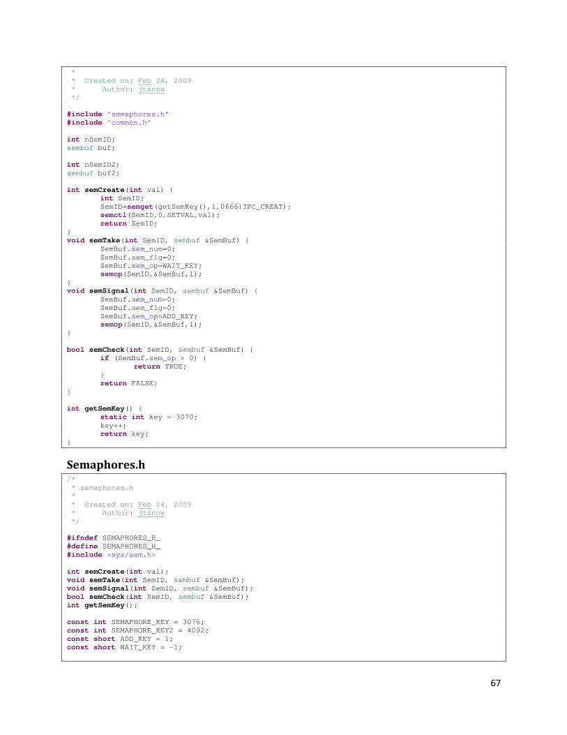
67
* * Created on: Feb 24, 2009 * Author: jtsnow */ #include "semaphores.h" #include "common.h" int nSemID; sembuf buf; int nSemID2; sembuf buf2; int semCreate(int val) { int SemID; SemID=semget(getSemKey(),1,0666|IPC_CREAT); semctl(SemID,0,SETVAL,val); return SemID; } void semTake(int SemID, sembuf &SemBuf) { SemBuf.sem_num=0; SemBuf.sem_flg=0; SemBuf.sem_op=WAIT_KEY; semop(SemID,&SemBuf,1); } void semSignal(int SemID, sembuf &SemBuf) { SemBuf.sem_num=0; SemBuf.sem_flg=0; SemBuf.sem_op=ADD_KEY; semop(SemID,&SemBuf,1); } bool semCheck(int SemID, sembuf &SemBuf) { if (SemBuf.sem_op > 0) { return TRUE; } return FALSE; } int getSemKey() { static int key = 3070; key++; return key; }
Semaphores.h /* * semaphores.h * * Created on: Feb 24, 2009 * Author: jtsnow */ #ifndef SEMAPHORES_H_ #define SEMAPHORES_H_ #include <sys/sem.h> int semCreate(int val); void semTake(int SemID, sembuf &SemBuf); void semSignal(int SemID, sembuf &SemBuf); bool semCheck(int SemID, sembuf &SemBuf); int getSemKey(); const int SEMAPHORE_KEY = 3076; const int SEMAPHORE_KEY2 = 4092; const short ADD_KEY = 1; const short WAIT_KEY = -1;

68
#endif /* SEMAPHORES_H_ */
Timer.cpp /* * Timer.cpp * * Created on: Mar 18, 2009 * Author: jtsnow */ #include "Timer.h" Timer::Timer() { isRunning = false; error = false; } time_t Timer::start() { time(&startTime); isRunning = true; error = false; return startTime; } time_t Timer::stop() { time(&stopTime); isRunning = false; return stopTime; } float Timer::elapsed() { if (isRunning) { return static_cast<float>(difftime(time(NULL), startTime)); } return static_cast<float>(difftime(stopTime, startTime)); // Return elapsed time in seconds. }
Timer.h /* * Timer.h * * Created on: Mar 18, 2009 * Author: jtsnow */ #ifndef SIMPLETIMER_H_ #define SIMPLETIMER_H_ #include <time.h> class Timer { public: time_t startTime; time_t stopTime; bool isRunning; bool error; Timer(); time_t start(); float elapsed(); time_t stop(); private: };
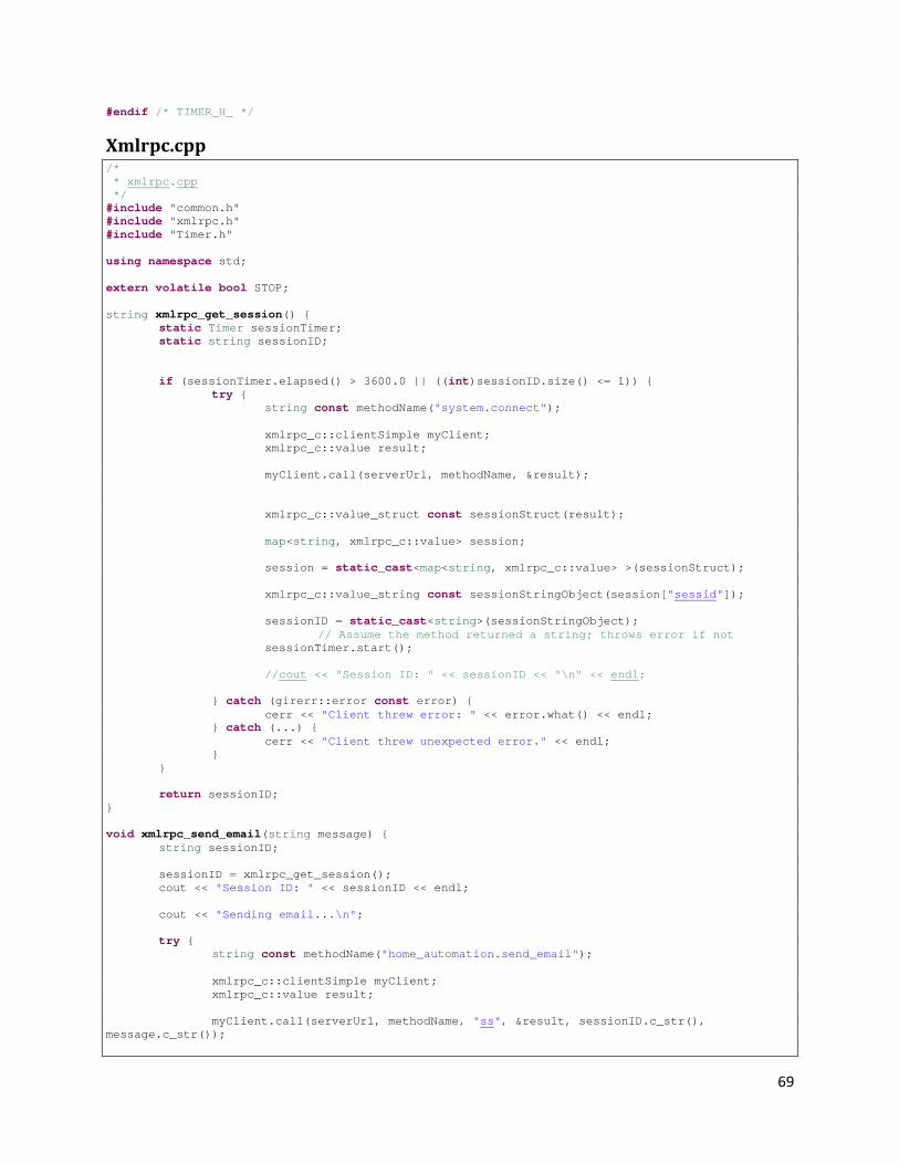
69
#endif /* TIMER_H_ */
Xmlrpc.cpp /* * xmlrpc.cpp */ #include "common.h" #include "xmlrpc.h" #include "Timer.h" using namespace std; extern volatile bool STOP; string xmlrpc_get_session() { static Timer sessionTimer; static string sessionID; if (sessionTimer.elapsed() > 3600.0 || ((int)sessionID.size() <= 1)) { try { string const methodName("system.connect"); xmlrpc_c::clientSimple myClient; xmlrpc_c::value result; myClient.call(serverUrl, methodName, &result); xmlrpc_c::value_struct const sessionStruct(result); map<string, xmlrpc_c::value> session; session = static_cast<map<string, xmlrpc_c::value> >(sessionStruct); xmlrpc_c::value_string const sessionStringObject(session["sessid"]); sessionID = static_cast<string>(sessionStringObject); // Assume the method returned a string; throws error if not sessionTimer.start(); //cout << "Session ID: " << sessionID << "\n" << endl; } catch (girerr::error const error) { cerr << "Client threw error: " << error.what() << endl; } catch (...) { cerr << "Client threw unexpected error." << endl; } } return sessionID; } void xmlrpc_send_email(string message) { string sessionID; sessionID = xmlrpc_get_session(); cout << "Session ID: " << sessionID << endl; cout << "Sending email...\n"; try { string const methodName("home_automation.send_email"); xmlrpc_c::clientSimple myClient; xmlrpc_c::value result; myClient.call(serverUrl, methodName, "ss", &result, sessionID.c_str(), message.c_str());

70
bool saved = xmlrpc_c::value_boolean(result); if (saved) { cout << "E-mail sent." << endl; } } catch (girerr::error const error) { cerr << "Client threw error: " << error.what() << endl; } catch (...) { cerr << "Client threw unexpected error." << endl; } } void xmlrpc_add_node(uint16_t NodeID) { string sessionID; sessionID = xmlrpc_get_session(); cout << "Session ID: " << sessionID << endl; //string *Name=static_cast<string *>(arg); try { string const methodName("home_automation.add_node"); xmlrpc_c::clientSimple myClient; xmlrpc_c::value result; myClient.call(serverUrl, methodName, "si", &result, sessionID.c_str(), NodeID); //myClient.call(serverUrl, "home_automation.add_node", "ss", &resultSum, sessionID.c_str(), 5, 7); bool saved = xmlrpc_c::value_boolean(result); if (saved) { cout << "Node saved to web server." << endl; } } catch (girerr::error const error) { cerr << "Client threw error: " << error.what() << endl; } catch (...) { cerr << "Client threw unexpected error." << endl; } } void xmlrpc_get_nodes() { string sessionID; sessionID = xmlrpc_get_session(); cout << "Session ID: " << sessionID << endl; cout << "Downloading node and device list...\n"; map<string, xmlrpc_c::value>::iterator it; map<string, xmlrpc_c::value>::iterator it_device; map<string, xmlrpc_c::value>::iterator it_element; string temp; Node tempNode; uint8_t devID; uint8_t type; uint8_t dev_class; try { string const methodName("home_automation.get_nodes"); xmlrpc_c::clientSimple myClient; xmlrpc_c::value result; myClient.call(serverUrl, methodName, "s", &result, sessionID.c_str());

71
xmlrpc_c::value_struct const xmlrpcStruct(result); map<string, xmlrpc_c::value> xmlrpcReturnMap; xmlrpcReturnMap = static_cast<map<string, xmlrpc_c::value> >(xmlrpcStruct); map<string, xmlrpc_c::value> xmlrpcNodeMap; map<string, xmlrpc_c::value> xmlrpcElementMap; for ( it=xmlrpcReturnMap.begin() ; it != xmlrpcReturnMap.end(); it++ ) { temp = (*it).first; tempNode.NodeId = (uint16_t)atoi(temp.c_str()); tempNode.isKnown = true; xmlrpcNodeMap = static_cast<map<string, xmlrpc_c::value> >(xmlrpc_c::value_struct((*it).second)); for (it_device = xmlrpcNodeMap.begin(); it_device != xmlrpcNodeMap.end(); it_device++) { //cout << "\t" << ((*it_device).first) << endl; xmlrpcElementMap = static_cast<map<string, xmlrpc_c::value> >(xmlrpc_c::value_struct((*it_device).second)); temp = static_cast<string>((xmlrpc_c::value_string(xmlrpcElementMap["device_id"]))); devID = atoi(temp.c_str()); temp = static_cast<string>((xmlrpc_c::value_string(xmlrpcElementMap["type"]))); type = static_cast<uint8_t>(temp[0]); temp = static_cast<string>((xmlrpc_c::value_string(xmlrpcElementMap["device_type"]))); dev_class = static_cast<uint8_t>(temp[0]); tempNode.AddDevice(devID, type, dev_class); } Nodes[tempNode.NodeId] = tempNode; } } catch (girerr::error const error) { cerr << "Client threw error: " << error.what() << endl; } catch (...) { cerr << "Client threw unexpected error." << endl; } } void xmlrpc_get_config() { string sessionID; sessionID = xmlrpc_get_session(); cout << "Session ID: " << sessionID << endl; cout << "Downloading config information...\n"; try { string const methodName("home_automation.get_config"); xmlrpc_c::clientSimple myClient; xmlrpc_c::value result; myClient.call(serverUrl, methodName, "s", &result, sessionID.c_str()); xmlrpc_c::value_struct const xmlrpcStruct(result); map<string, xmlrpc_c::value> xmlrpcReturnMap; xmlrpcReturnMap = static_cast<map<string, xmlrpc_c::value> >(xmlrpcStruct); if (sample_rate != static_cast<uint16_t>(xmlrpc_c::value_int(xmlrpcReturnMap["sample_rate"]))) {
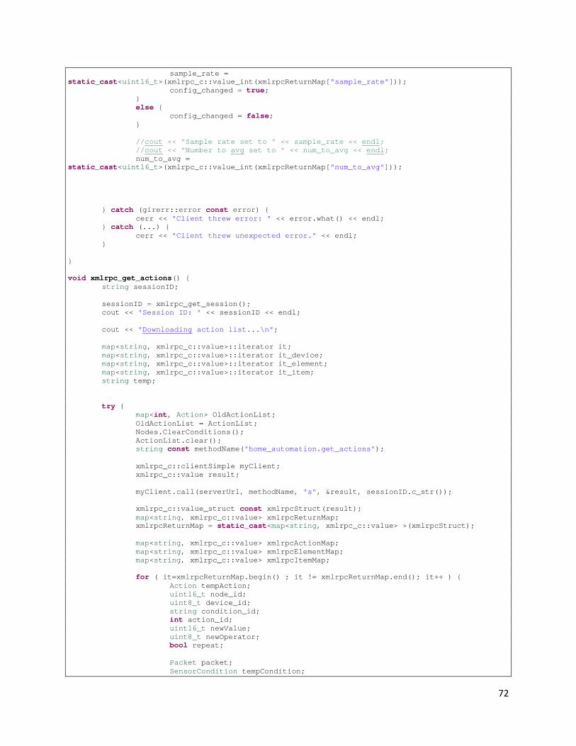
72
sample_rate = static_cast<uint16_t>(xmlrpc_c::value_int(xmlrpcReturnMap["sample_rate"])); config_changed = true; } else { config_changed = false; } //cout << "Sample rate set to " << sample_rate << endl; //cout << "Number to avg set to " << num_to_avg << endl; num_to_avg = static_cast<uint16_t>(xmlrpc_c::value_int(xmlrpcReturnMap["num_to_avg"])); } catch (girerr::error const error) { cerr << "Client threw error: " << error.what() << endl; } catch (...) { cerr << "Client threw unexpected error." << endl; } } void xmlrpc_get_actions() { string sessionID; sessionID = xmlrpc_get_session(); cout << "Session ID: " << sessionID << endl; cout << "Downloading action list...\n"; map<string, xmlrpc_c::value>::iterator it; map<string, xmlrpc_c::value>::iterator it_device; map<string, xmlrpc_c::value>::iterator it_element; map<string, xmlrpc_c::value>::iterator it_item; string temp; try { map<int, Action> OldActionList; OldActionList = ActionList; Nodes.ClearConditions(); ActionList.clear(); string const methodName("home_automation.get_actions"); xmlrpc_c::clientSimple myClient; xmlrpc_c::value result; myClient.call(serverUrl, methodName, "s", &result, sessionID.c_str()); xmlrpc_c::value_struct const xmlrpcStruct(result); map<string, xmlrpc_c::value> xmlrpcReturnMap; xmlrpcReturnMap = static_cast<map<string, xmlrpc_c::value> >(xmlrpcStruct); map<string, xmlrpc_c::value> xmlrpcActionMap; map<string, xmlrpc_c::value> xmlrpcElementMap; map<string, xmlrpc_c::value> xmlrpcItemMap; for ( it=xmlrpcReturnMap.begin() ; it != xmlrpcReturnMap.end(); it++ ) { Action tempAction; uint16_t node_id; uint8_t device_id; string condition_id; int action_id; uint16_t newValue; uint8_t newOperator; bool repeat; Packet packet; SensorCondition tempCondition;
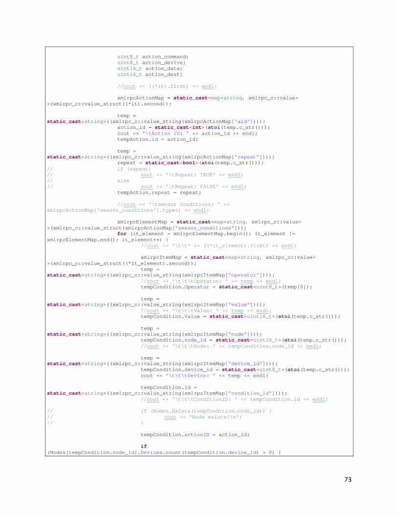
73
uint8_t action_command; uint8_t action_device; uint16_t action_data; uint16_t action_dest; //cout << ((*it).first) << endl; xmlrpcActionMap = static_cast<map<string, xmlrpc_c::value> >(xmlrpc_c::value_struct((*it).second)); temp = static_cast<string>((xmlrpc_c::value_string(xmlrpcActionMap["aid"]))); action_id = static_cast<int>(atoi(temp.c_str())); cout << "\tAction ID: " << action_id << endl; tempAction.id = action_id; temp = static_cast<string>((xmlrpc_c::value_string(xmlrpcActionMap["repeat"]))); repeat = static_cast<bool>(atoi(temp.c_str())); // if (repeat) // cout << "\tRepeat: TRUE" << endl; // else // cout << "\tRepeat: FALSE" << endl; tempAction.repeat = repeat; //cout << "\tSensor Conditions: " << xmlrpcActionMap["sensor_conditions"].type() << endl; xmlrpcElementMap = static_cast<map<string, xmlrpc_c::value> >(xmlrpc_c::value_struct(xmlrpcActionMap["sensor_conditions"])); for (it_element = xmlrpcElementMap.begin(); it_element != xmlrpcElementMap.end(); it_element++) { //cout << "\t\t" << ((*it_element).first) << endl; xmlrpcItemMap = static_cast<map<string, xmlrpc_c::value> >(xmlrpc_c::value_struct((*it_element).second)); temp = static_cast<string>((xmlrpc_c::value_string(xmlrpcItemMap["operator"]))); //cout << "\t\t\tOperator: " << temp << endl; tempCondition.Operator = static_cast<uint8_t>(temp[0]); temp = static_cast<string>((xmlrpc_c::value_string(xmlrpcItemMap["value"]))); //cout << "\t\t\tValue: " << temp << endl; tempCondition.Value = static_cast<uint16_t>(atoi(temp.c_str())); temp = static_cast<string>((xmlrpc_c::value_string(xmlrpcItemMap["node"]))); tempCondition.node_id = static_cast<uint16_t>(atoi(temp.c_str())); //cout << "\t\t\tNode: " << tempCondition.node_id << endl; temp = static_cast<string>((xmlrpc_c::value_string(xmlrpcItemMap["device_id"]))); tempCondition.device_id = static_cast<uint8_t>(atoi(temp.c_str())); cout << "\t\t\tDevice: " << temp << endl; tempCondition.id = static_cast<string>((xmlrpc_c::value_string(xmlrpcItemMap["condition_id"]))); //cout << "\t\t\tConditionID: " << tempCondition.id << endl; // if (Nodes.Exists(tempCondition.node_id)) { // cout << "Node exists!\n"; // } tempCondition.actionID = action_id; if (Nodes[tempCondition.node_id].Devices.count(tempCondition.device_id) > 0) {

74
Nodes[tempCondition.node_id].Devices[tempCondition.device_id].AddCondition(tempCondition); tempAction.AddCondition(tempCondition.id); } } //cout << "\tAction Packets: " << endl; xmlrpcElementMap = static_cast<map<string, xmlrpc_c::value> >(xmlrpc_c::value_struct(xmlrpcActionMap["actions"])); for (it_element = xmlrpcElementMap.begin(); it_element != xmlrpcElementMap.end(); it_element++) { //cout << "\t\t" << ((*it_element).first) << endl; xmlrpcItemMap = static_cast<map<string, xmlrpc_c::value> >(xmlrpc_c::value_struct((*it_element).second)); temp = static_cast<string>((xmlrpc_c::value_string(xmlrpcItemMap["command"]))); if (temp.compare("email") != 0) { action_command = static_cast<uint8_t>(temp[0]); //cout << "\t\t\tCommand: " << temp << endl; temp = static_cast<string>((xmlrpc_c::value_string(xmlrpcItemMap["value"]))); action_data = static_cast<uint16_t>(atoi(temp.c_str())); //cout << "\t\t\tValue: " << temp << endl; temp = static_cast<string>((xmlrpc_c::value_string(xmlrpcItemMap["node"]))); action_dest = static_cast<uint16_t>(atoi(temp.c_str())); //cout << "\t\t\tNode: " << temp << endl; temp = static_cast<string>((xmlrpc_c::value_string(xmlrpcItemMap["device_id"]))); action_device = static_cast<uint8_t>(atoi(temp.c_str())); cout << "\t\t\tDevice: " << temp << endl; packet.Set(action_command, P_COMMAND, action_device, action_data, action_dest); tempAction.AddPacket(packet); } else { tempAction.sendEmail = true; tempAction.email_message = static_cast<string>((xmlrpc_c::value_string(xmlrpcItemMap["value"]))); } } if (OldActionList.count(tempAction.id) > 0) { tempAction.triggered = OldActionList[tempAction.id].triggered; } ActionList[action_id] = tempAction; } cout << "Number of actions: " << ActionList.size() << endl << endl; } catch (girerr::error const error) { cerr << "Client threw error: " << error.what() << endl; } catch (...) { cerr << "Client threw unexpected error." << endl; } } void xmlrpc_add_sensor(uint16_t NodeID, uint8_t DeviceID, uint8_t DeviceType, uint8_t Type) { string sessionID; sessionID = xmlrpc_get_session();
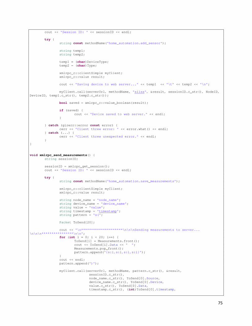
75
cout << "Session ID: " << sessionID << endl; try { string const methodName("home_automation.add_sensor"); string temp1; string temp2; temp1 = (char)DeviceType; temp2 = (char)Type; xmlrpc_c::clientSimple myClient; xmlrpc_c::value result; cout << "Saving device to web server..." << temp1 << "\t" << temp2 << "\n"; myClient.call(serverUrl, methodName, "siiss", &result, sessionID.c_str(), NodeID, DeviceID, temp1.c_str(), temp2.c_str()); bool saved = xmlrpc_c::value_boolean(result); if (saved) { cout << "Device saved to web server." << endl; } } catch (girerr::error const error) { cerr << "Client threw error: " << error.what() << endl; } catch (...) { cerr << "Client threw unexpected error." << endl; } } void xmlrpc_send_measurements() { string sessionID; sessionID = xmlrpc_get_session(); cout << "Session ID: " << sessionID << endl; try { string const methodName("home_automation.save_measurements"); xmlrpc_c::clientSimple myClient; xmlrpc_c::value result; string node_name = "node_name"; string device_name = "device_name"; string value = "value"; string timestamp = "timestamp"; string pattern = "s("; Packet ToSend[20]; cout << "\n*********************\n\n\nSending measurements to server... \n\n\n****************\n\n"; for (int i = 0; i < 20; i++) { ToSend[i] = Measurements.front(); cout << ToSend[i].Data << " "; Measurements.pop_front(); pattern.append("{s:i,s:i,s:i,s:i}"); } cout << endl; pattern.append(")"); myClient.call(serverUrl, methodName, pattern.c_str(), &result, sessionID.c_str(), node_name.c_str(), ToSend[0].Source, device_name.c_str(), ToSend[0].Device, value.c_str(), ToSend[0].Data, timestamp.c_str(), (int)ToSend[0].timestamp,

76
node_name.c_str(), ToSend[0].Source, device_name.c_str(), ToSend[0].Device, value.c_str(), ToSend[0].Data, timestamp.c_str(), (int)ToSend[0].timestamp, node_name.c_str(), ToSend[1].Source, device_name.c_str(), ToSend[1].Device, value.c_str(), ToSend[1].Data, timestamp.c_str(), (int)ToSend[1].timestamp, node_name.c_str(), ToSend[2].Source, device_name.c_str(), ToSend[2].Device, value.c_str(), ToSend[2].Data, timestamp.c_str(), (int)ToSend[2].timestamp, node_name.c_str(), ToSend[3].Source, device_name.c_str(), ToSend[3].Device, value.c_str(), ToSend[3].Data, timestamp.c_str(), (int)ToSend[3].timestamp, node_name.c_str(), ToSend[4].Source, device_name.c_str(), ToSend[4].Device, value.c_str(), ToSend[4].Data, timestamp.c_str(), (int)ToSend[4].timestamp, node_name.c_str(), ToSend[5].Source, device_name.c_str(), ToSend[5].Device, value.c_str(), ToSend[5].Data, timestamp.c_str(), (int)ToSend[5].timestamp, node_name.c_str(), ToSend[6].Source, device_name.c_str(), ToSend[6].Device, value.c_str(), ToSend[6].Data, timestamp.c_str(), (int)ToSend[6].timestamp, node_name.c_str(), ToSend[7].Source, device_name.c_str(), ToSend[7].Device, value.c_str(), ToSend[7].Data, timestamp.c_str(), (int)ToSend[7].timestamp, node_name.c_str(), ToSend[8].Source, device_name.c_str(), ToSend[8].Device, value.c_str(), ToSend[8].Data, timestamp.c_str(), (int)ToSend[8].timestamp, node_name.c_str(), ToSend[9].Source, device_name.c_str(), ToSend[9].Device, value.c_str(), ToSend[9].Data, timestamp.c_str(), (int)ToSend[9].timestamp, node_name.c_str(), ToSend[10].Source, device_name.c_str(), ToSend[10].Device, value.c_str(), ToSend[10].Data, timestamp.c_str(), (int)ToSend[10].timestamp, node_name.c_str(), ToSend[11].Source, device_name.c_str(), ToSend[11].Device, value.c_str(), ToSend[11].Data, timestamp.c_str(), (int)ToSend[11].timestamp, node_name.c_str(), ToSend[12].Source, device_name.c_str(), ToSend[12].Device, value.c_str(), ToSend[12].Data, timestamp.c_str(), (int)ToSend[12].timestamp, node_name.c_str(), ToSend[13].Source, device_name.c_str(), ToSend[13].Device, value.c_str(), ToSend[13].Data, timestamp.c_str(), (int)ToSend[13].timestamp, node_name.c_str(), ToSend[14].Source,

77
device_name.c_str(), ToSend[14].Device, value.c_str(), ToSend[14].Data, timestamp.c_str(), (int)ToSend[14].timestamp, node_name.c_str(), ToSend[15].Source, device_name.c_str(), ToSend[15].Device, value.c_str(), ToSend[15].Data, timestamp.c_str(), (int)ToSend[15].timestamp, node_name.c_str(), ToSend[16].Source, device_name.c_str(), ToSend[16].Device, value.c_str(), ToSend[16].Data, timestamp.c_str(), (int)ToSend[16].timestamp, node_name.c_str(), ToSend[17].Source, device_name.c_str(), ToSend[17].Device, value.c_str(), ToSend[17].Data, timestamp.c_str(), (int)ToSend[17].timestamp, node_name.c_str(), ToSend[18].Source, device_name.c_str(), ToSend[18].Device, value.c_str(), ToSend[18].Data, timestamp.c_str(), (int)ToSend[18].timestamp, node_name.c_str(), ToSend[19].Source, device_name.c_str(), ToSend[19].Device, value.c_str(), ToSend[19].Data, timestamp.c_str(), (int)ToSend[19].timestamp ); bool saved = xmlrpc_c::value_boolean(result); if (saved) { cout << "Measurements saved to web server." << endl; } } catch (girerr::error const error) { cerr << "Client threw error: " << error.what() << endl; } catch (...) { cerr << "Client threw unexpected error." << endl; } } void xmlrpc_send_struct() { string sessionID; sessionID = xmlrpc_get_session(); cout << "Session ID: " << sessionID << endl; try { string const methodName("home_automation.struct_test"); xmlrpc_c::clientSimple myClient; xmlrpc_c::value result; string node_name = "node_name"; string device_name = "device_name"; string value = "value"; string timestamp = "timestamp"; int a = 12; int b = 15; int c = 102; printf("Came here 1\n"); myClient.call(serverUrl, methodName, "s({s:i,s:i,s:i}{s:i,s:i,s:i})", &result, sessionID.c_str(), node_name.c_str(), a, device_name.c_str(), b, value.c_str(), c, node_name.c_str(), a,

78
device_name.c_str(), b, value.c_str(), c ); printf("Came here 2\n"); bool saved = xmlrpc_c::value_boolean(result); if (saved) { cout << "Sent struct to web server." << endl; } } catch (girerr::error const error) { cerr << "Client threw error: " << error.what() << endl; } catch (...) { cerr << "Client threw unexpected error." << endl; } }
Xmlrpc.h /* * xmlrpc.h * */ #ifndef XMLRPC_H_ #define XMLRPC_H_ #include <map> #include <list> #include "common.h" #include "node.h" #include "NodeList.h" #include "Action.h" #include <xmlrpc-c/girerr.hpp> #include <xmlrpc-c/base.hpp> #include <xmlrpc-c/client_simple.hpp> std::string const serverUrl("http://deviable.com/automation/services/xmlrpc"); void *xmlrpc(void *arg); void xmlrpc_add_node(uint16_t); std::string xmlrpc_get_session(); void xmlrpc_get_nodes(); void xmlrpc_add_sensor(uint16_t, uint8_t, uint8_t, uint8_t); void xmlrpc_send_measurements(); void xmlrpc_send_struct(); void xmlrpc_get_config(); void xmlrpc_get_actions(); void xmlrpc_send_email(std::string); std::list<Packet> Measurements; extern NodeList Nodes; extern std::map<int, Action> ActionList; extern bool AddAction(Action); #endif /* XMLRPC_H_ */
Appendix B: Code for Web Server/User Interface
home_automation.install <?php

79
// $Id$ /** * Implementation of hook_install(). */ function home_automation_install() { // Create tables. drupal_install_schema('home_automation'); } /** * Implementation of hook_schema(). */ function home_automation_schema() { $schema['home_automation_nodes'] = array( 'description' => t('Stores information for nodes. A node may have many devices (sensors/actuators).'), 'fields' => array( 'nid' => array( 'type' => 'serial', 'unsigned' => TRUE, 'not null' => TRUE, 'description' => t('The ID of the field, defined by the database.'), ), 'machine_name' => array( 'type' => 'int', 'length' => '16', 'not null' => TRUE, 'default' => 0, 'description' => t('Machine name of the node.'), ), 'title' => array( 'type' => 'varchar', 'length' => '128', 'not null' => TRUE, 'default' => '', 'description' => t('Human-readable name of sensor.'), ), ), 'indexes' => array( 'machine_name' => array('machine_name'), ), 'primary key' => array('nid'), 'unique keys' => array( 'name' => array('machine_name'), ), ); $schema['home_automation_sensors'] = array( 'description' => t('Stores information for sensors and actuators.'), 'fields' => array( 'sid' => array( 'type' => 'serial', 'unsigned' => TRUE, 'not null' => TRUE, 'description' => t('The ID of the field, defined by the database.'), ), 'nid' => array( 'description' => 'The node ID associated with this device.', 'type' => 'int', 'unsigned' => TRUE, 'not null' => TRUE, 'default' => 0 ), 'machine_name' => array( 'description' => 'The name/number of the device.', 'type' => 'varchar', 'length' => '64', 'not null' => TRUE, 'default' => '', ),
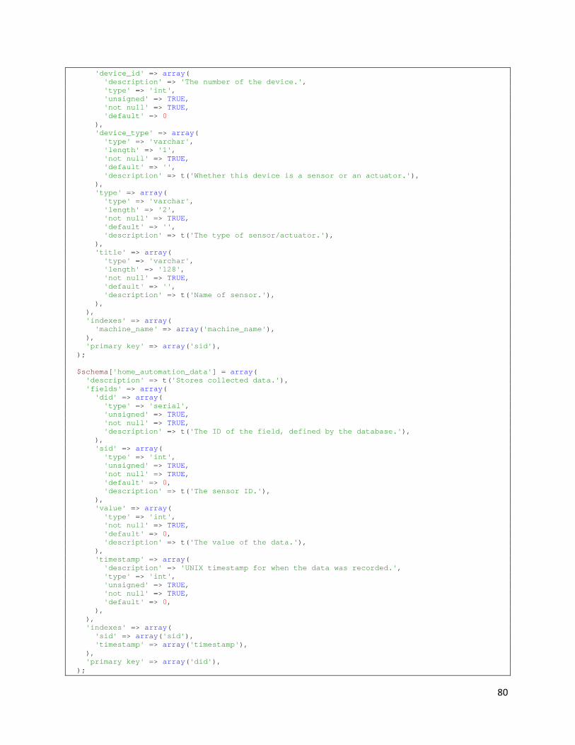
80
'device_id' => array( 'description' => 'The number of the device.', 'type' => 'int', 'unsigned' => TRUE, 'not null' => TRUE, 'default' => 0 ), 'device_type' => array( 'type' => 'varchar', 'length' => '1', 'not null' => TRUE, 'default' => '', 'description' => t('Whether this device is a sensor or an actuator.'), ), 'type' => array( 'type' => 'varchar', 'length' => '2', 'not null' => TRUE, 'default' => '', 'description' => t('The type of sensor/actuator.'), ), 'title' => array( 'type' => 'varchar', 'length' => '128', 'not null' => TRUE, 'default' => '', 'description' => t('Name of sensor.'), ), ), 'indexes' => array( 'machine_name' => array('machine_name'), ), 'primary key' => array('sid'), ); $schema['home_automation_data'] = array( 'description' => t('Stores collected data.'), 'fields' => array( 'did' => array( 'type' => 'serial', 'unsigned' => TRUE, 'not null' => TRUE, 'description' => t('The ID of the field, defined by the database.'), ), 'sid' => array( 'type' => 'int', 'unsigned' => TRUE, 'not null' => TRUE, 'default' => 0, 'description' => t('The sensor ID.'), ), 'value' => array( 'type' => 'int', 'not null' => TRUE, 'default' => 0, 'description' => t('The value of the data.'), ), 'timestamp' => array( 'description' => 'UNIX timestamp for when the data was recorded.', 'type' => 'int', 'unsigned' => TRUE, 'not null' => TRUE, 'default' => 0, ), ), 'indexes' => array( 'sid' => array('sid'), 'timestamp' => array('timestamp'), ), 'primary key' => array('did'), );
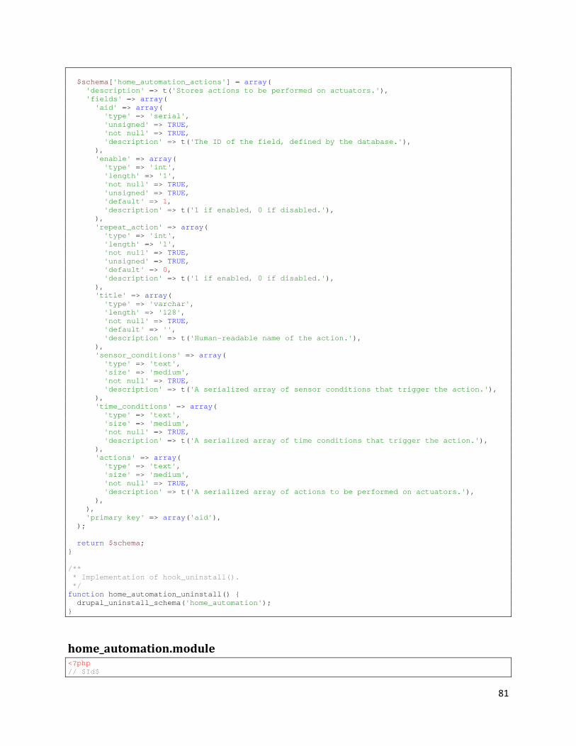
81
$schema['home_automation_actions'] = array( 'description' => t('Stores actions to be performed on actuators.'), 'fields' => array( 'aid' => array( 'type' => 'serial', 'unsigned' => TRUE, 'not null' => TRUE, 'description' => t('The ID of the field, defined by the database.'), ), 'enable' => array( 'type' => 'int', 'length' => '1', 'not null' => TRUE, 'unsigned' => TRUE, 'default' => 1, 'description' => t('1 if enabled, 0 if disabled.'), ), 'repeat_action' => array( 'type' => 'int', 'length' => '1', 'not null' => TRUE, 'unsigned' => TRUE, 'default' => 0, 'description' => t('1 if enabled, 0 if disabled.'), ), 'title' => array( 'type' => 'varchar', 'length' => '128', 'not null' => TRUE, 'default' => '', 'description' => t('Human-readable name of the action.'), ), 'sensor_conditions' => array( 'type' => 'text', 'size' => 'medium', 'not null' => TRUE, 'description' => t('A serialized array of sensor conditions that trigger the action.'), ), 'time_conditions' => array( 'type' => 'text', 'size' => 'medium', 'not null' => TRUE, 'description' => t('A serialized array of time conditions that trigger the action.'), ), 'actions' => array( 'type' => 'text', 'size' => 'medium', 'not null' => TRUE, 'description' => t('A serialized array of actions to be performed on actuators.'), ), ), 'primary key' => array('aid'), ); return $schema; } /** * Implementation of hook_uninstall(). */ function home_automation_uninstall() { drupal_uninstall_schema('home_automation'); }
home_automation.module <?php // $Id$
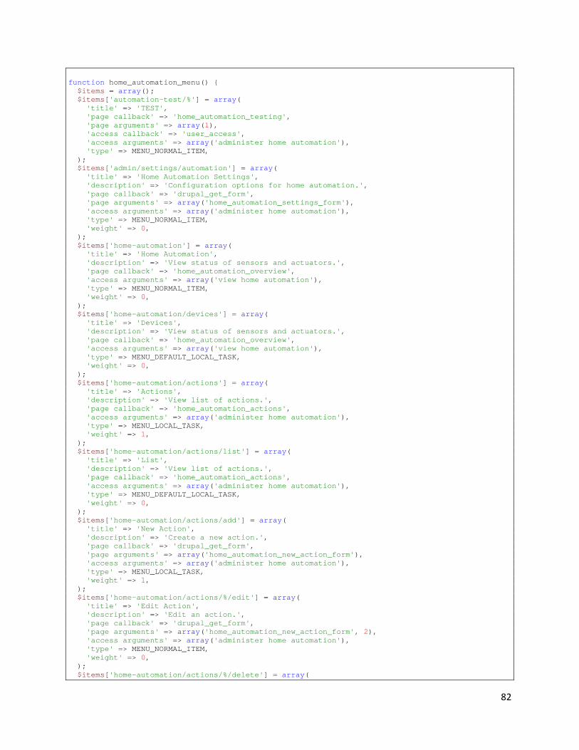
82
function home_automation_menu() { $items = array(); $items['automation-test/%'] = array( 'title' => 'TEST', 'page callback' => 'home_automation_testing', 'page arguments' => array(1), 'access callback' => 'user_access', 'access arguments' => array('administer home automation'), 'type' => MENU_NORMAL_ITEM, ); $items['admin/settings/automation'] = array( 'title' => 'Home Automation Settings', 'description' => 'Configuration options for home automation.', 'page callback' => 'drupal_get_form', 'page arguments' => array('home_automation_settings_form'), 'access arguments' => array('administer home automation'), 'type' => MENU_NORMAL_ITEM, 'weight' => 0, ); $items['home-automation'] = array( 'title' => 'Home Automation', 'description' => 'View status of sensors and actuators.', 'page callback' => 'home_automation_overview', 'access arguments' => array('view home automation'), 'type' => MENU_NORMAL_ITEM, 'weight' => 0, ); $items['home-automation/devices'] = array( 'title' => 'Devices', 'description' => 'View status of sensors and actuators.', 'page callback' => 'home_automation_overview', 'access arguments' => array('view home automation'), 'type' => MENU_DEFAULT_LOCAL_TASK, 'weight' => 0, ); $items['home-automation/actions'] = array( 'title' => 'Actions', 'description' => 'View list of actions.', 'page callback' => 'home_automation_actions', 'access arguments' => array('administer home automation'), 'type' => MENU_LOCAL_TASK, 'weight' => 1, ); $items['home-automation/actions/list'] = array( 'title' => 'List', 'description' => 'View list of actions.', 'page callback' => 'home_automation_actions', 'access arguments' => array('administer home automation'), 'type' => MENU_DEFAULT_LOCAL_TASK, 'weight' => 0, ); $items['home-automation/actions/add'] = array( 'title' => 'New Action', 'description' => 'Create a new action.', 'page callback' => 'drupal_get_form', 'page arguments' => array('home_automation_new_action_form'), 'access arguments' => array('administer home automation'), 'type' => MENU_LOCAL_TASK, 'weight' => 1, ); $items['home-automation/actions/%/edit'] = array( 'title' => 'Edit Action', 'description' => 'Edit an action.', 'page callback' => 'drupal_get_form', 'page arguments' => array('home_automation_new_action_form', 2), 'access arguments' => array('administer home automation'), 'type' => MENU_NORMAL_ITEM, 'weight' => 0, ); $items['home-automation/actions/%/delete'] = array(

83
'title' => 'Delete Action', 'description' => 'Delete an action.', 'page callback' => 'drupal_get_form', 'page arguments' => array('home_automation_action_delete_confirm', 2), 'access arguments' => array('administer home automation'), 'type' => MENU_NORMAL_ITEM, 'weight' => 0, ); $items['home-automation/sensor/%'] = array( 'page callback' => 'home_automation_view_sensor', 'page arguments' => array(2), 'access callback' => 'user_access', 'access arguments' => array('view home automation'), ); $items['home-automation/sensor/%/view'] = array( 'title' => 'View', 'page callback' => 'home_automation_view_sensor', 'page arguments' => array(2), 'access callback' => 'user_access', 'access arguments' => array('view home automation'), 'type' => MENU_DEFAULT_LOCAL_TASK, 'weight' => -5, ); $items['home-automation/sensor/%/edit'] = array( 'title' => 'Edit', 'page callback' => 'drupal_get_form', 'page arguments' => array('home_automation_edit_sensor_form'), 'access callback' => 'user_access', 'access arguments' => array('administer home automation'), 'type' => MENU_LOCAL_TASK, ); $items['home-automation/actuator/%/edit'] = array( 'title' => 'Edit', 'page callback' => 'drupal_get_form', 'page arguments' => array('home_automation_edit_actuator_form'), 'access callback' => 'user_access', 'access arguments' => array('administer home automation'), 'type' => MENU_LOCAL_TASK, ); $items['home-automation/node/%'] = array( 'title' => 'View', 'page callback' => 'home_automation_view_node', 'page arguments' => array(2), 'access callback' => 'user_access', 'access arguments' => array('view home automation'), ); $items['home-automation/node/%/view'] = array( 'title' => 'View', 'page callback' => 'home_automation_view_node', 'page arguments' => array(2), 'access callback' => 'user_access', 'access arguments' => array('view home automation'), 'type' => MENU_DEFAULT_LOCAL_TASK, 'weight' => -5, ); $items['home-automation/node/%/edit'] = array( 'title' => 'Edit', 'page callback' => 'drupal_get_form', 'page arguments' => array('home_automation_edit_node_form'), 'access callback' => 'user_access', 'access arguments' => array('administer home automation'), 'type' => MENU_LOCAL_TASK, ); return $items; } /** * Implementation of hook_theme(). */ function home_automation_theme($existing, $type, $theme, $path) { return array(

84
'home_automation_new_action_form' => array( 'arguments' => array('form' => NULL), ), 'time_field_time' => array( 'arguments' => array('element' => NULL), ), ); } function home_automation_perm() { return array('administer home automation', 'view home automation'); } /** * Implementation of hook_service() */ function home_automation_service() { return array( // sensor.addtest array( '#method' => 'sensor.addtest', '#callback' => 'home_automation_add', '#auth' => true, '#return' => 'int', '#args' => array( array( '#name' => 'op1', '#type' => 'int', '#description' => t('The first operand.'), ), array( '#name' => 'op2', '#type' => 'int', '#description' => t('The second operand.'), ), ), '#help' => t('Returns the sum of two integers.') ), // home_automation.save_measurements array( '#method' => 'home_automation.save_measurements', '#callback' => 'home_automation_save_measurements', '#auth' => true, '#return' => 'bool', '#args' => array( array( '#name' => 'measurements', '#type' => 'array', '#description' => t('An array of measurement structs.'), ), ), '#help' => t('Saves sensor measurements to the database.') ), // home_automation.add_node array( '#method' => 'home_automation.send_email', '#callback' => 'home_automation_notify', '#auth' => true, '#return' => 'bool', '#args' => array( array( '#name' => 'message', '#type' => 'string', '#description' => t('A message to be e-mailed to the specified notification address.'), ),

85
), '#help' => t('Sends a notification email.') ), // home_automation.add_node array( '#method' => 'home_automation.add_node', '#callback' => 'home_automation_add_node', '#auth' => true, '#return' => 'bool', '#args' => array( array( '#name' => 'name', '#type' => 'int', '#description' => t('A unique number identifying the node.'), ), ), '#help' => t('Saves new node to the database.') ), // home_automation.get_nodes array( '#method' => 'home_automation.get_nodes', '#callback' => 'home_automation_get_nodes', '#auth' => true, '#return' => 'struct', '#args' => array(), '#help' => t('Gets an array of nodes in the database.') ), // home_automation.get_actions array( '#method' => 'home_automation.get_actions', '#callback' => 'home_automation_get_actions', '#auth' => true, '#return' => 'struct', '#args' => array(), '#help' => t('Gets an array of actions from the database.') ), // home_automation.get_config array( '#method' => 'home_automation.get_config', '#callback' => 'home_automation_get_config', '#auth' => true, '#return' => 'struct', '#args' => array(), '#help' => t('Gets configuration information.') ), // home_automation.struct_test array( '#method' => 'home_automation.struct_test', '#callback' => 'home_automation_struct_test', '#auth' => true, '#return' => 'bool', '#args' => array( array( '#name' => 'myStruct', '#type' => 'array', '#description' => t('A test structure.'), ), ), '#help' => t('Test.') ), // home_automation.add_sensor home_automation_add_sensor($node_name, $sensor_name, $device_type, $type) array( '#method' => 'home_automation.add_sensor',

86
'#callback' => 'home_automation_add_sensor', '#auth' => true, '#return' => 'bool', '#args' => array( array( '#name' => 'node_name', '#type' => 'int', '#description' => t('A unique number identifying the node.'), ), array( '#name' => 'device_name', '#type' => 'int', '#description' => t('A unique number identifying the device.'), ), array( '#name' => 'device_type', '#type' => 'string', '#description' => t('S for sensor and A for actuator.'), ), array( '#name' => 'type', '#type' => 'string', '#description' => t('The type of sensor or actuator'), ), ), '#help' => t('Adds sensor or actuator information to the database.') ), ); } function home_automation_get_nodes() { $return = new stdClass; $result = db_query("SELECT * FROM {home_automation_nodes}"); $count = 0; while ($node = db_fetch_object($result)) { $node = new automation_node($node->nid); $devices = array(); foreach($node->sensors as $id => $sensor) { $temp = new stdClass; $temp->device_id = $sensor->device_id; $temp->type = $sensor->type; $temp->device_type = $sensor->device_type; $devices[$sensor->device_id] = $temp; } foreach($node->actuators as $id => $sensor) { $temp = new stdClass; $temp->device_id = $sensor->device_id; $temp->type = $sensor->type; $temp->device_type = $sensor->device_type; $devices[$sensor->device_id] = $temp; } $return->{$node->name} = $devices; $count++; } return $return; } function home_automation_get_actions() { $list = new stdClass; $result = db_query("SELECT * FROM {home_automation_actions} WHERE enable = 1"); while ($action = db_fetch_object($result)) { $time_valid = true; $action_object = new automation_action(); $action_object->aid = $action->aid; //$action_object->enable = $action->enable; $action_object->repeat = $action->repeat_action; //$action_object->title = $action->title; $action_object->sensor_conditions = unserialize($action->sensor_conditions);

87
foreach ($action_object->sensor_conditions as $id => $sensor_condition) { //drupal_set_message("Value:" . $sensor_condition['value'] . " Type: " . gettype($sensor_condition['value'])); if (is_double($sensor_condition['value'])) { //drupal_set_message("Came here."); $action_object->sensor_conditions[$id]['value'] = (string)(round($sensor_condition['value'], 0)); } } $time_conditions = unserialize($action->time_conditions); if (isset($time_conditions['date'])) { $current_time = time(); $start_date = mktime(0, 0, 0, $time_conditions['date']['start']['month'], $time_conditions['date']['start']['day'], $time_conditions['date']['start']['year']); $end_date = mktime(0, 0, 0, $time_conditions['date']['end']['month'], $time_conditions['date']['end']['day'], $time_conditions['date']['end']['year']); if ($current_time < $start_date || $current_time > $end_date) { $time_valid = false; } } if (isset($time_conditions['time'])) { $current_time = time(); $date = format_date($current_time, 'custom', 'j'); $month = format_date($current_time, 'custom', 'n'); $year = format_date($current_time, 'custom', 'Y'); $time = $time_conditions['time']['start']; $time['hour'] = date("H",strtotime($time['hour']. ":00 " . $time['meridiem'])); $time_start = mktime($time['hour'], $time['minute'], 0, $month, $date, $year) + 21600; $time = $time_conditions['time']['end']; $time['hour'] = date("H",strtotime($time['hour']. ":00 " . $time['meridiem'])); $time_end = mktime($time['hour'], $time['minute'], 0, $month, $date, $year) + 21600; if ($current_time < $time_start || $current_time > $time_end) { $time_valid = false; } // $time_conditions['time']['starttime'] = format_date($time_start); // $time_conditions['time']['currenttime'] = format_date($current_time); // $time_conditions['time']['endtime'] = format_date($time_end); } $action_object->time_conditions = $time_conditions; unset($action_object->time_conditions); unset($action_object->title); unset($action_object->enable); $action_object->actions = unserialize($action->actions); if ($time_valid) { $list->{$action->aid} = $action_object; } } return $list; } function home_automation_list_actions() { $list = new stdClass; $result = db_query("SELECT * FROM {home_automation_actions}"); while ($action = db_fetch_object($result)) { $action_object = new automation_action(); $action_object->aid = $action->aid; $action_object->enable = $action->enable; $action_object->repeat = $action->repeat_action; $action_object->title = $action->title;

88
$action_object->sensor_conditions = unserialize($action->sensor_conditions); $action_object->time_conditions = unserialize($action->time_conditions); $action_object->actions = unserialize($action->actions); $list->{$action->aid} = $action_object; } return $list; } function home_automation_get_config() { $config = new stdClass; $config->sample_rate = (int)variable_get('home_automation_sample_rate', 10); $config->num_to_avg = (int)variable_get('home_automation_sensor_average', 20); return $config; } function home_automation_get_devices() { // $return = new stdClass; // $result = db_query("SELECT * FROM {home_automation_sensors}"); // $count = 0; // while ($device = db_fetch_object($result)) { // $node = new automation_node($device->nid); // $return->{'CI' . $device->machine_name . 'DD' . chr(($node->name >> 8) & 15) . chr($node->name & 15) . 'WW'} = $node->machine_name; // $count++; // } // // return $return; } function home_automation_add_node($name) { $new_node = new automation_node($name, TRUE); //watchdog("HomeAutomation", "Add Node: <pre>" . print_r($name, TRUE) . "</pre>", NULL); if (!isset($new_node->nid)) { $new_node->name = $name; $new_node->title = "Node[$name]"; $new_node->save(); return TRUE; } return FALSE; } function home_automation_save_measurements($measurements) { foreach ($measurements as $measurement) { $sensor = new sensor($measurement['node_name'] . '-' . $measurement['device_name'], TRUE); $sensor->value = $measurement['value']; $sensor->timestamp = $measurement['timestamp']; $sensor->save_data(); } //watchdog("HomeAutomation", "<pre>" . print_r($measurements, TRUE) . "</pre>", NULL); return true; } function home_automation_data_save($node_name, $sensor_name, $value, $timestamp) { //$sensor = home_automation_sensor_load($device . '-' . $sensorID); $sensor = new sensor($node_name . '-' . $sensor_name); // if (!isset($sensor->sid)) { // $sensor->device = $device; // $sensor->name = $device . '-' . $sensorID; // $sensor->type = $type; // $sensor->save(); // } $sensor->value = $value; $sensor->timestamp = $timestamp; //drupal_set_message("<pre>" . print_r($sensor, TRUE) . "</pre>"); return $sensor->save_data(); } function home_automation_struct_test($myStruct) {
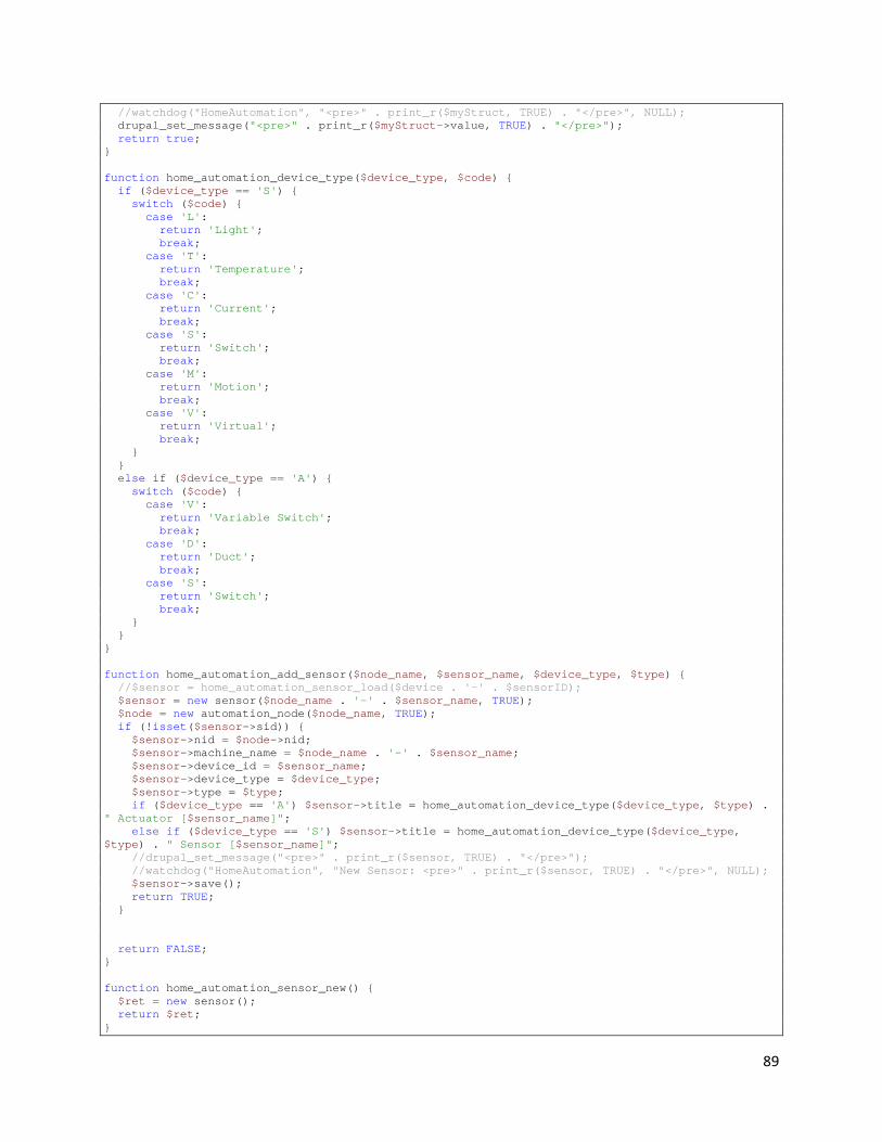
89
//watchdog("HomeAutomation", "<pre>" . print_r($myStruct, TRUE) . "</pre>", NULL); drupal_set_message("<pre>" . print_r($myStruct->value, TRUE) . "</pre>"); return true; } function home_automation_device_type($device_type, $code) { if ($device_type == 'S') { switch ($code) { case 'L': return 'Light'; break; case 'T': return 'Temperature'; break; case 'C': return 'Current'; break; case 'S': return 'Switch'; break; case 'M': return 'Motion'; break; case 'V': return 'Virtual'; break; } } else if ($device_type == 'A') { switch ($code) { case 'V': return 'Variable Switch'; break; case 'D': return 'Duct'; break; case 'S': return 'Switch'; break; } } } function home_automation_add_sensor($node_name, $sensor_name, $device_type, $type) { //$sensor = home_automation_sensor_load($device . '-' . $sensorID); $sensor = new sensor($node_name . '-' . $sensor_name, TRUE); $node = new automation_node($node_name, TRUE); if (!isset($sensor->sid)) { $sensor->nid = $node->nid; $sensor->machine_name = $node_name . '-' . $sensor_name; $sensor->device_id = $sensor_name; $sensor->device_type = $device_type; $sensor->type = $type; if ($device_type == 'A') $sensor->title = home_automation_device_type($device_type, $type) . " Actuator [$sensor_name]"; else if ($device_type == 'S') $sensor->title = home_automation_device_type($device_type, $type) . " Sensor [$sensor_name]"; //drupal_set_message("<pre>" . print_r($sensor, TRUE) . "</pre>"); //watchdog("HomeAutomation", "New Sensor: <pre>" . print_r($sensor, TRUE) . "</pre>", NULL); $sensor->save(); return TRUE; } return FALSE; } function home_automation_sensor_new() { $ret = new sensor(); return $ret; }
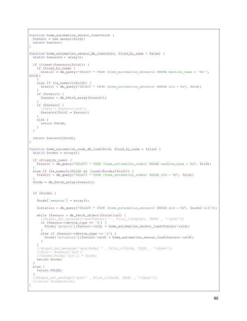
90
function home_automation_sensor_load($sid) { $sensor = new sensor($sid); return $sensor; } function home_automation_sensor_db_load($sid, $load_by_name = false) { static $sensors = array(); if (!isset($sensors[$sid])) { if ($load_by_name) { $result = db_query("SELECT * FROM {home_automation_sensors} WHERE machine_name = '%s'", $sid); } else if (is_numeric($sid)) { $result = db_query("SELECT * FROM {home_automation_sensors} WHERE sid = %d", $sid); } if ($result) { $sensor = db_fetch_array($result); } if ($sensor) { //$sid = $sensor['sid']; $sensors[$sid] = $sensor; } else { return FALSE; } } return $sensors[$sid]; } function home_automation_node_db_load($nid, $load_by_name = false) { static $nodes = array(); if ($load_by_name) { $result = db_query("SELECT * FROM {home_automation_nodes} WHERE machine_name = %d", $nid); } else if (is_numeric($nid) && !isset($nodes[$nid])) { $result = db_query("SELECT * FROM {home_automation_nodes} WHERE nid = %d", $nid); } $node = db_fetch_array($result); if ($node) { $node['sensors'] = array(); $relation = db_query("SELECT * FROM {home_automation_sensors} WHERE nid = %d", $node['nid']); while ($sensor = db_fetch_object($relation)) { //drupal_set_message("<pre>Sensor: " . Print_r($sensor, TRUE) . "</pre>"); if ($sensor->device_type == 'S') { $node['sensors'][$sensor->sid] = home_automation_sensor_load($sensor->sid); } else if ($sensor->device_type == 'A') { $node['actuators'][$sensor->sid] = home_automation_sensor_load($sensor->sid); } } //drupal_set_message("<pre>Node: " . Print_r($node, TRUE) . "</pre>"); //$sid = $sensor['sid']; //$nodes[$node['nid']] = $node; return $node; } else { return FALSE; } //drupal_set_message("<pre>" . Print_r($node, TRUE) . "</pre>"); //return $nodes[$nid]; }

91
function home_automation_action_db_load($aid) { if (is_numeric($aid)) { $result = db_query("SELECT * FROM {home_automation_actions} WHERE aid = %d", $aid); } $action = db_fetch_array($result); if ($action) { $action['sensor_conditions'] = unserialize($action['sensor_conditions']); $action['time_conditions'] = unserialize($action['time_conditions']); $action['actions'] = unserialize($action['actions']); return $action; } return FALSE; } function home_automation_node_list() { $nodes = home_automation_get_nodes(); $list = array(); foreach ($nodes as $name => $info) { $node = new automation_node($name, TRUE); $list[$node->nid] = $node; } return $list; } class automation_node { public $nid; public $name; public $title; public $sensors = array(); public $actuators = array(); function __construct($nid = NULL, $load_by_name = false) { if (isset($nid)) { $this->load($nid, $load_by_name); } } protected function load($nid, $load_by_name = false) { $node = home_automation_node_db_load($nid, $load_by_name); if ($node) { $this->nid = $node['nid']; $this->name = $node['machine_name']; $this->title = $node['title']; $this->sensors = is_array($node['sensors']) ? $node['sensors'] : array(); $this->actuators = is_array($node['actuators']) ? $node['actuators'] : array(); //print "Loading!" . "<br>"; //print Print_r($sensor, TRUE); return TRUE; } return FALSE; } public function save() { $return = FALSE; if (isset($this->nid) && is_numeric($this->nid)) { db_query("UPDATE {home_automation_nodes} SET machine_name = '%s', title = '%s' WHERE nid = %d", $this->name, $this->title, $this->nid); $return = SAVED_UPDATED; } else { db_query("INSERT INTO {home_automation_nodes} (machine_name, title) VALUES ('%s', '%s')", $this->name, $this->title); $this->nid = db_last_insert_id("home_automation_nodes", "nid"); $return = SAVED_NEW; } return $return; } }

92
class sensor { public $sid; public $type; public $device_id; public $device_type; public $device_type_name; public $nid; public $machine_name; public $title; public $value; public $timestamp; public $data = array(); function __construct($sid = NULL, $load_by_name = false) { if ($sid) { if (!$this->load($sid, $load_by_name)) { //drupal_set_message(t('Sensor could not be loaded.'), 'warning'); } } } protected function load($sid, $load_by_name) { //if (!is_numeric($sid)) { // return FALSE; // TODO: Load via string of device & sensor number //} $sensor = home_automation_sensor_db_load($sid, $load_by_name); if ($sensor) { $this->sid = $sensor['sid']; $this->nid = $sensor['nid']; $this->device_id = $sensor['device_id']; $this->type = $sensor['type']; $this->machine_name = $sensor['machine_name']; $this->title = $sensor['title']; $this->device_type = $sensor['device_type']; $this->device_type_name = home_automation_device_type($this->device_type, $this->type); //print "Loading!" . "<br>"; //print Print_r($sensor, TRUE); return TRUE; } else { return FALSE; } } public function save() { if (isset($this->sid) && is_numeric($this->sid)) { db_query("UPDATE {home_automation_sensors} SET nid = '%d', machine_name = '%s', device_id = '%d', device_type = '%s', type = '%s', title = '%s' WHERE sid = %d", $this->nid, $this->machine_name, $this->device_id, $this->device_type, $this->type, $this->title, $this->sid); $return = SAVED_UPDATED; } else { db_query("INSERT INTO {home_automation_sensors} (nid, machine_name, device_id, device_type, type, title) VALUES ('%d', '%s', '%d', '%s', '%s', '%s')", $this->nid, $this->machine_name, $this->device_id, $this->device_type, $this->type, $this->title); $this->sid = db_last_insert_id("home_automation_sensors", "sid"); $return = SAVED_NEW; } return $return; } public function save_data() { if (isset($this->sid) && is_numeric($this->sid)) { db_query("INSERT INTO {home_automation_data} (sid, value, timestamp) VALUES ('%d', '%d', '%d')", $this->sid, $this->value, $this->timestamp); return true; }

93
return false; } public function load_data() { if (isset($this->sid) && is_numeric($this->sid)) { $result = db_query("SELECT * FROM {home_automation_data} WHERE sid = %d ORDER BY timestamp ASC", $this->sid); // ASC = earliest first. while ($data_item = db_fetch_array($result)) { $this->data[$data_item['timestamp']] = $this->scale_data($data_item['value']); } } return $this->data; } public function get_last_sample() { if (isset($this->sid) && is_numeric($this->sid)) { $result = db_query("SELECT * FROM {home_automation_data} WHERE sid = %d ORDER BY timestamp DESC LIMIT 1", $this->sid); } $sample = db_fetch_array($result); $this->scale_data($sample['value']); return $sample; } public function get_highest_sample() { if (isset($this->sid) && is_numeric($this->sid)) { $result = db_query("SELECT * FROM {home_automation_data} WHERE sid = %d ORDER BY value DESC LIMIT 1", $this->sid); } $sample = db_fetch_array($result); $this->scale_data($sample['value']); return $sample; } public function get_lowest_sample() { if (isset($this->sid) && is_numeric($this->sid)) { $result = db_query("SELECT * FROM {home_automation_data} WHERE sid = %d ORDER BY value ASC LIMIT 1", $this->sid); } $sample = db_fetch_array($result); $this->scale_data($sample['value']); return $sample; } public function scale_data(&$value) { if ($this->type == 'T') { if (variable_get('home_automation_temp_sensor_scale', 'F') != 'R' && is_numeric($value)) { $value = ($value - 551.24) / 8.72; if (variable_get('home_automation_temp_sensor_scale', 'F') == 'F') { $value = $value * (9/5) + 32; //C * 9 / 5 + 32 = F } } } return $value; } } function temp_to_raw(&$value) { if (variable_get('home_automation_temp_sensor_scale', 'F') != 'R' && is_numeric($value)) { if (variable_get('home_automation_temp_sensor_scale', 'F') == 'F') { $value = ($value - 32) / (9/5); } $value = $value * 8.72 + 551.24; } return $value; }
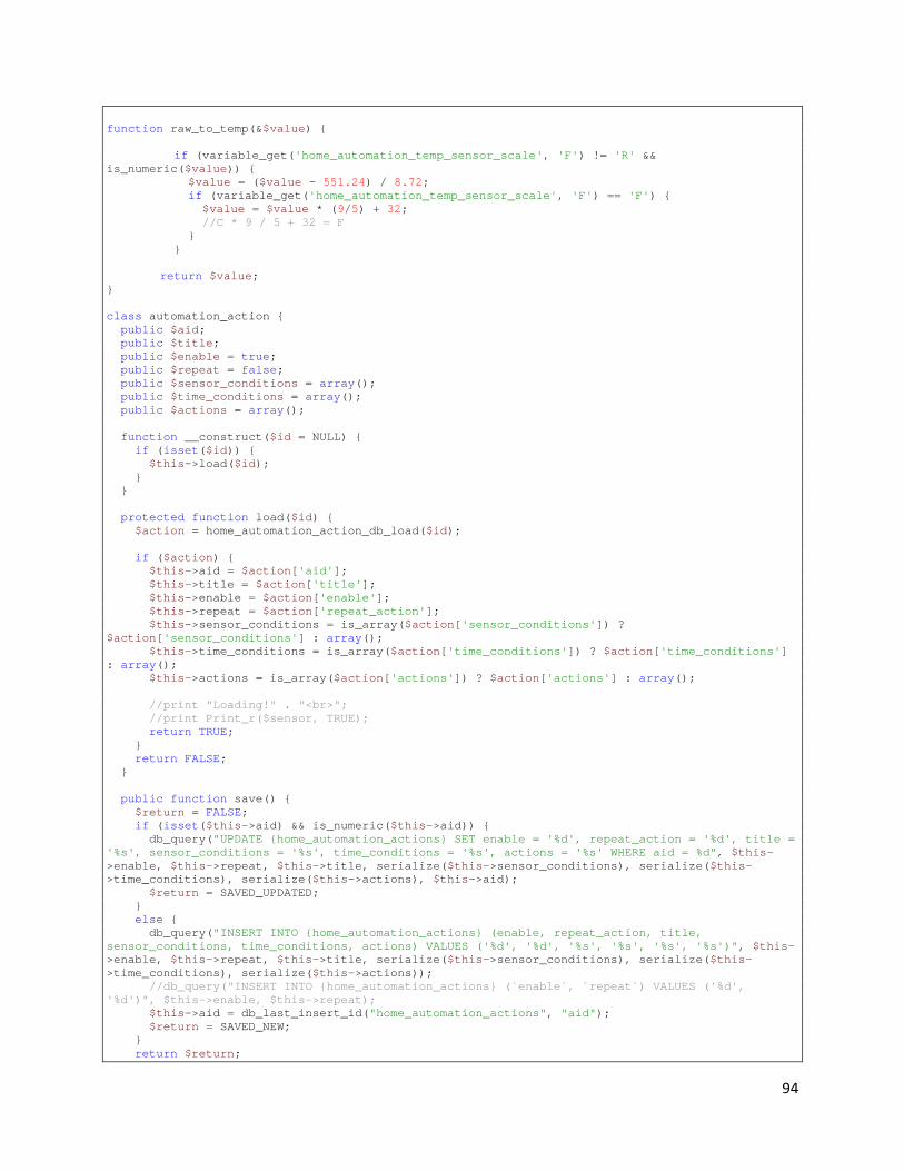
94
function raw_to_temp(&$value) { if (variable_get('home_automation_temp_sensor_scale', 'F') != 'R' && is_numeric($value)) { $value = ($value - 551.24) / 8.72; if (variable_get('home_automation_temp_sensor_scale', 'F') == 'F') { $value = $value * (9/5) + 32; //C * 9 / 5 + 32 = F } } return $value; } class automation_action { public $aid; public $title; public $enable = true; public $repeat = false; public $sensor_conditions = array(); public $time_conditions = array(); public $actions = array(); function __construct($id = NULL) { if (isset($id)) { $this->load($id); } } protected function load($id) { $action = home_automation_action_db_load($id); if ($action) { $this->aid = $action['aid']; $this->title = $action['title']; $this->enable = $action['enable']; $this->repeat = $action['repeat_action']; $this->sensor_conditions = is_array($action['sensor_conditions']) ? $action['sensor_conditions'] : array(); $this->time_conditions = is_array($action['time_conditions']) ? $action['time_conditions'] : array(); $this->actions = is_array($action['actions']) ? $action['actions'] : array(); //print "Loading!" . "<br>"; //print Print_r($sensor, TRUE); return TRUE; } return FALSE; } public function save() { $return = FALSE; if (isset($this->aid) && is_numeric($this->aid)) { db_query("UPDATE {home_automation_actions} SET enable = '%d', repeat_action = '%d', title = '%s', sensor_conditions = '%s', time_conditions = '%s', actions = '%s' WHERE aid = %d", $this->enable, $this->repeat, $this->title, serialize($this->sensor_conditions), serialize($this->time_conditions), serialize($this->actions), $this->aid); $return = SAVED_UPDATED; } else { db_query("INSERT INTO {home_automation_actions} (enable, repeat_action, title, sensor_conditions, time_conditions, actions) VALUES ('%d', '%d', '%s', '%s', '%s', '%s')", $this->enable, $this->repeat, $this->title, serialize($this->sensor_conditions), serialize($this->time_conditions), serialize($this->actions)); //db_query("INSERT INTO {home_automation_actions} (`enable`, `repeat`) VALUES ('%d', '%d')", $this->enable, $this->repeat); $this->aid = db_last_insert_id("home_automation_actions", "aid"); $return = SAVED_NEW; } return $return;

95
} public function delete() { if (isset($this->aid) && is_numeric($this->aid)) { db_query("DELETE FROM {home_automation_actions} WHERE aid = %d", $this->aid); return TRUE; } return FALSE; } } /** * FAPI definition for the home automation configuration form. * * @ingroup forms */ function home_automation_settings_form() { $form = array(); $form['sensor'] = array( '#type' => 'fieldset', '#title' => t('Sensor Settings'), '#collapsible' => TRUE, ); $form['sensor']['home_automation_sample_rate'] = array( '#type' => 'textfield', '#title' => t('Sensor Sample Rate'), '#default_value' => variable_get('home_automation_sample_rate', 10), '#size' => 4, '#maxlength' => 4, '#required' => TRUE, '#description' => t('The sensor sample rate in seconds.'), ); $form['sensor']['home_automation_sensor_average'] = array( '#type' => 'textfield', '#title' => t('Sample Average'), '#default_value' => variable_get('home_automation_sensor_average', 20), '#size' => 4, '#maxlength' => 4, '#required' => TRUE, '#description' => t('The number of samples to average before saving.'), ); $form['sensor']['home_automation_temp_sensor_scale'] = array( '#type' => 'select', '#title' => t('Temperature Sensor Scale'), '#default_value' => variable_get('home_automation_temp_sensor_scale', 'F'), '#required' => FALSE, '#options' => array('F' => t('Fahrenheit'), 'C' => t('Celsius'), 'R' => t('Raw Samples')), '#description' => t('Select how the temperature readings should be interpreted.'), ); $form['sensor']['home_automation_email_notify'] = array( '#type' => 'textfield', '#title' => t('Notification E-mail'), '#default_value' => variable_get('home_automation_email_notify', ""), '#size' => 30, '#maxlength' => 50, '#required' => FALSE, '#description' => t('The e-mail address that notifications are sent to.'), ); $form = system_settings_form($form); return $form; } function home_automation_edit_sensor_form () { $sensor = new sensor(arg(2)); drupal_set_title('Edit ' . $sensor->title); $form['sid'] = array( '#type' => 'value', '#value' => $sensor->sid,

96
); $form['sensor_title'] = array( '#type' => 'textfield', '#title' => t('Rename Sensor'), '#default_value' => $sensor->title, '#size' => 40, '#maxlength' => 40, '#required' => FALSE, '#description' => t('You may enter a new name for this sensor.'), ); $form['submit'] = array('#type' => 'submit', '#value' => t('Save')); return $form; } function home_automation_edit_sensor_form_submit($form, &$form_state) { $sensor = new sensor($form_state['values']['sid']); $sensor->title = $form_state['values']['sensor_title']; $sensor->save(); drupal_set_message(t('Your changes have been saved.')); } function home_automation_edit_actuator_form () { $sensor = new sensor(arg(2)); drupal_set_title('Edit ' . $sensor->title); $form['sid'] = array( '#type' => 'value', '#value' => $sensor->sid, ); $form['sensor_title'] = array( '#type' => 'textfield', '#title' => t('Rename Actuator'), '#default_value' => $sensor->title, '#size' => 40, '#maxlength' => 40, '#required' => FALSE, '#description' => t('You may enter a new name for this actuator.'), ); $form['submit'] = array('#type' => 'submit', '#value' => t('Save')); return $form; } function home_automation_edit_actuator_form_submit($form, &$form_state) { $sensor = new sensor($form_state['values']['sid']); $sensor->title = $form_state['values']['sensor_title']; $sensor->save(); drupal_set_message(t('Your changes have been saved.')); } function home_automation_edit_node_form () { $node = new automation_node(arg(2)); drupal_set_title('Edit ' . $node->title); $form['nid'] = array( '#type' => 'value', '#value' => $node->nid, ); $form['node_title'] = array( '#type' => 'textfield', '#title' => t('Rename Node'), '#default_value' => $node->title, '#size' => 40, '#maxlength' => 40, '#required' => FALSE, '#description' => t('You may enter a new name for this node.'), ); $form['submit'] = array('#type' => 'submit', '#value' => t('Save')); return $form; } function home_automation_edit_node_form_submit($form, &$form_state) { $node = new automation_node($form_state['values']['nid']); $node->title = $form_state['values']['node_title'];

97
$node->save(); drupal_set_message(t('Your changes have been saved.')); } function home_automation_sensor_value_field($type) { switch ($type) { case 'T': $form = array( '#type' => 'textfield', '#default_value' => '', '#size' => 20, '#maxlength' => 25, '#required' => FALSE, '#prefix' => '<div class="container-inline">', '#suffix' => ' degrees</div>', ); break; case 'L': $form = array( '#type' => 'textfield', '#default_value' => '', '#size' => 20, '#maxlength' => 25, '#required' => FALSE, '#prefix' => '<div class="container-inline">', '#suffix' => ' lux</div>', ); break; case 'M': $form = array( '#type' => 'select', '#required' => FALSE, '#options' => array(t('No Motion Detected'), t('Motion Detected')), ); break; } return $form; } function home_automation_sensor_operation_field($type) { switch ($type) { case 'M': $form = array( '#type' => 'value', '#value' => 'e', ); break; default: $form = array( '#type' => 'select', '#options' => array( 'l' => t('Less Than'), 'g' => t('Greater Than'), 'e' => t('Equal To'), ), '#required' => FALSE, ); break; } return $form; } function home_automation_actuator_value_field($type) { switch ($type) { case 'D': $form['command'] = array( '#type' => 'select', '#options' => array( 'O' => t('Open'), 'F' => t('Close'), ),

98
'#required' => FALSE, ); $form['value'] = array( '#type' => 'value', '#value' => '1', ); break; case 'S': $form['command'] = array( '#type' => 'select', '#required' => FALSE, '#options' => array( 'O' => t('On'), 'F' => t('Off'), ), ); $form['value'] = array( '#type' => 'value', '#value' => '1', ); break; case 'V': $form['command'] = array( '#type' => 'select', '#options' => array( 'O' => t('On'), 'F' => t('Off'), 'S' => t('Set'), '+' => t('Increase'), '-' => t('Decrease'), ), '#prefix' => '<div class="container-inline">', ); $form['value'] = array( '#type' => 'textfield', '#default_value' => '', '#size' => 20, '#maxlength' => 25, '#description' => t('Only used with the "Set" option.'), '#suffix' => '</div>', ); break; } return $form; } function home_automation_actions() { $actions = home_automation_list_actions(); $rows = array(); $header = array( array('data' => t('Title')), array('data' => t('Enabled')), array('data' => t('Operations'), 'colspan' => '2'), ); foreach ($actions as $action) { //drupal_set_message("Actuators:<pre>" . Print_r($node->actuators, TRUE) . "</pre>"); $enable = $action->enable ? t('Yes') : t('No'); $rows[] = array($action->title, $enable, l(t('Edit'), 'home-automation/actions/'. $action->aid .'/edit'), l(t('Delete'), 'home-automation/actions/'. $action->aid .'/delete')); } $form = array(); $form['actions'] = array( '#type' => 'fieldset', '#title' => t('Actions'), '#collapsible' => FALSE, //'#description' => t('A list of sensors receiving data.'), ); $content = theme('table', $header, $rows, array('style' => 'margin-top:0;'));
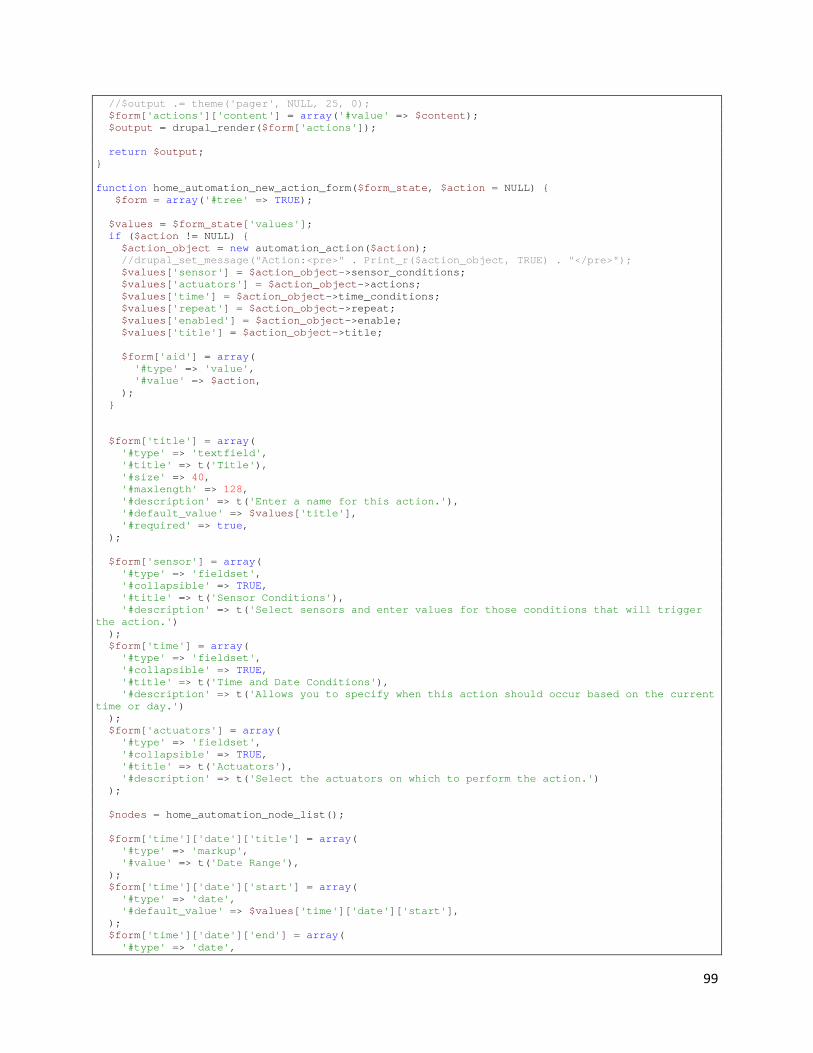
99
//$output .= theme('pager', NULL, 25, 0); $form['actions']['content'] = array('#value' => $content); $output = drupal_render($form['actions']); return $output; } function home_automation_new_action_form($form_state, $action = NULL) { $form = array('#tree' => TRUE); $values = $form_state['values']; if ($action != NULL) { $action_object = new automation_action($action); //drupal_set_message("Action:<pre>" . Print_r($action_object, TRUE) . "</pre>"); $values['sensor'] = $action_object->sensor_conditions; $values['actuators'] = $action_object->actions; $values['time'] = $action_object->time_conditions; $values['repeat'] = $action_object->repeat; $values['enabled'] = $action_object->enable; $values['title'] = $action_object->title; $form['aid'] = array( '#type' => 'value', '#value' => $action, ); } $form['title'] = array( '#type' => 'textfield', '#title' => t('Title'), '#size' => 40, '#maxlength' => 128, '#description' => t('Enter a name for this action.'), '#default_value' => $values['title'], '#required' => true, ); $form['sensor'] = array( '#type' => 'fieldset', '#collapsible' => TRUE, '#title' => t('Sensor Conditions'), '#description' => t('Select sensors and enter values for those conditions that will trigger the action.') ); $form['time'] = array( '#type' => 'fieldset', '#collapsible' => TRUE, '#title' => t('Time and Date Conditions'), '#description' => t('Allows you to specify when this action should occur based on the current time or day.') ); $form['actuators'] = array( '#type' => 'fieldset', '#collapsible' => TRUE, '#title' => t('Actuators'), '#description' => t('Select the actuators on which to perform the action.') ); $nodes = home_automation_node_list(); $form['time']['date']['title'] = array( '#type' => 'markup', '#value' => t('Date Range'), ); $form['time']['date']['start'] = array( '#type' => 'date', '#default_value' => $values['time']['date']['start'], ); $form['time']['date']['end'] = array( '#type' => 'date',

100
'#default_value' => $values['time']['date']['end'], ); $form['time']['date']['enable'] = array( '#type' => 'checkbox', '#default_value' => $values['time']['date']['enable'], ); $form['time']['time']['title'] = array( '#type' => 'markup', '#value' => t('Time of Day'), ); $form['time']['time']['start'] = array( '#type' => 'time_field_time', '#default_value' => isset($values['time']['time']['start']) ? $values['time']['time']['start'] : variable_get('test_reset_time', array('hour' => 12, 'minute' => 0, 'meridiem' => 'pm')), ); $form['time']['time']['end'] = array( '#type' => 'time_field_time', '#default_value' => isset($values['time']['time']['end']) ? $values['time']['time']['end'] : variable_get('test_reset_time', array('hour' => 12, 'minute' => 0, 'meridiem' => 'pm')), ); $form['time']['time']['enable'] = array( '#type' => 'checkbox', '#default_value' => $values['time']['time']['enable'], ); foreach ($nodes as $node) { foreach ($node->sensors as $sensor) { $form['sensor'][$sensor->sid]['title'] = array( '#type' => 'markup', '#value' => $sensor->title, ); $form['sensor'][$sensor->sid]['operator'] = home_automation_sensor_operation_field($sensor->type); $form['sensor'][$sensor->sid]['operator']['#default_value'] = $values['sensor'][$sensor->sid]['operator']; $form['sensor'][$sensor->sid]['value'] = home_automation_sensor_value_field($sensor->type); $form['sensor'][$sensor->sid]['value']['#default_value'] = $sensor->scale_data($values['sensor'][$sensor->sid]['value']); //$form['sensor'][$sensor->sid]['value']['#default_value'] = $values['sensor'][$sensor->sid]['value']; $form['sensor'][$sensor->sid]['enable'] = array( '#type' => 'checkbox', '#default_value' => $values['sensor'][$sensor->sid]['enable'], ); $form['sensor'][$sensor->sid]['node'] = array( '#type' => 'value', '#value' => $node->name, ); $form['sensor'][$sensor->sid]['device_id'] = array( '#type' => 'value', '#value' => $sensor->device_id, ); $form['sensor'][$sensor->sid]['type'] = array( '#type' => 'value', '#value' => $sensor->type, ); } foreach ($node->actuators as $actuator) { $form['actuators'][$actuator->sid]['title'] = array( '#type' => 'markup', '#value' => $actuator->title, ); $form['actuators'][$actuator->sid] += home_automation_actuator_value_field($actuator->type); $form['actuators'][$actuator->sid]['command']['#default_value'] = $values['actuators'][$actuator->sid]['command']; $form['actuators'][$actuator->sid]['value']['#default_value'] = $values['actuators'][$actuator->sid]['value'];

101
$form['actuators'][$actuator->sid]['enable'] = array( '#type' => 'checkbox', '#default_value' => $values['actuators'][$actuator->sid]['enable'], ); $form['actuators'][$actuator->sid]['node'] = array( '#type' => 'value', '#value' => $node->name, ); $form['actuators'][$actuator->sid]['device_id'] = array( '#type' => 'value', '#value' => $actuator->device_id, ); } } $form['actuators']['email']['title'] = array( '#type' => 'markup', '#value' => t('E-mail Notification'), ); $form['actuators']['email']['value'] = array( '#type' => 'textfield', '#default_value' => $values['actuators']['email']['value'], '#size' => 25, '#maxlength' => 255, ); $form['actuators']['email']['command'] = array( '#type' => 'value', '#value' => 'email', ); $form['actuators']['email']['enable'] = array( '#type' => 'checkbox', '#default_value' => $values['actuators']['email']['enable'], ); $form['repeat'] = array( '#title' => t('Repeat Action'), '#type' => 'checkbox', '#description' => t('Checking this box will cause the action to be continually triggered for as long as all the conditions are met. If unchecked, the action will only trigger once each time all the sensor conditions are met.'), '#default_value' => $values['repeat'], ); $form['enabled'] = array( '#title' => t('Enable'), '#type' => 'checkbox', '#description' => t('Uncheck this box to disable this action.'), '#default_value' => $values['enabled'], ); $form['submit'] = array( '#type' => 'submit', '#value' => t('Save Action'), '#weight' => 19, ); return $form; } /** * Format the action creation form. * * @param $form * The FAPI form data. * @ingroup themeable */ function theme_home_automation_new_action_form($form) { $rows = array();

102
foreach (element_children($form['sensor']) as $key) { $sensor = &$form['sensor'][$key]; $row = array(); $row[] = array('data' => drupal_render($sensor['enable'])); $row[] = array('data' => drupal_render($sensor['title'])); $row[] = array('data' => drupal_render($sensor['operator'])); $row[] = array('data' => drupal_render($sensor['value'])); //$row[] = drupal_render($source); $rows[] = array('data' => $row); } if (empty($rows)) { $rows[] = array(array('data' => t('No sensors exist.'), 'colspan' => '2')); } $header = array( t('Enable'), t('Sensor Name'), t('Operator'), t('Value'), ); $form['sensor']['table'] = array( '#type' => 'markup', '#value' => theme('table', $header, $rows, array('id' => 'sensor-table')), ); $rows = array(); foreach (element_children($form['time']) as $key) { $time = &$form['time'][$key]; $row = array(); $row[] = array('data' => drupal_render($time['enable'])); $row[] = array('data' => drupal_render($time['title'])); $row[] = array('data' => drupal_render($time['start'])); $row[] = array('data' => drupal_render($time['end'])); $rows[] = array('data' => $row); } if (empty($rows)) { $rows[] = array(array('data' => t('No actuators exist.'), 'colspan' => '2')); } $header = array( t('Enable'), t('Name'), t('Begin'), t('End'), ); $form['time']['table'] = array( '#type' => 'markup', '#value' => theme('table', $header, $rows, array('id' => 'time-table')), ); $rows = array(); foreach (element_children($form['actuators']) as $key) { $actuator = &$form['actuators'][$key]; $row = array(); $row[] = array('data' => drupal_render($actuator['enable'])); $row[] = array('data' => drupal_render($actuator['title'])); $row[] = array('data' => drupal_render($actuator['command']) . drupal_render($actuator['value'])); $rows[] = array('data' => $row); } if (empty($rows)) { $rows[] = array(array('data' => t('No actuators exist.'), 'colspan' => '2')); } $header = array( t('Enable'), t('Actuator Name'), t('Value'), ); $form['actuators']['table'] = array( '#type' => 'markup', '#value' => theme('table', $header, $rows, array('id' => 'actuator-table')), );
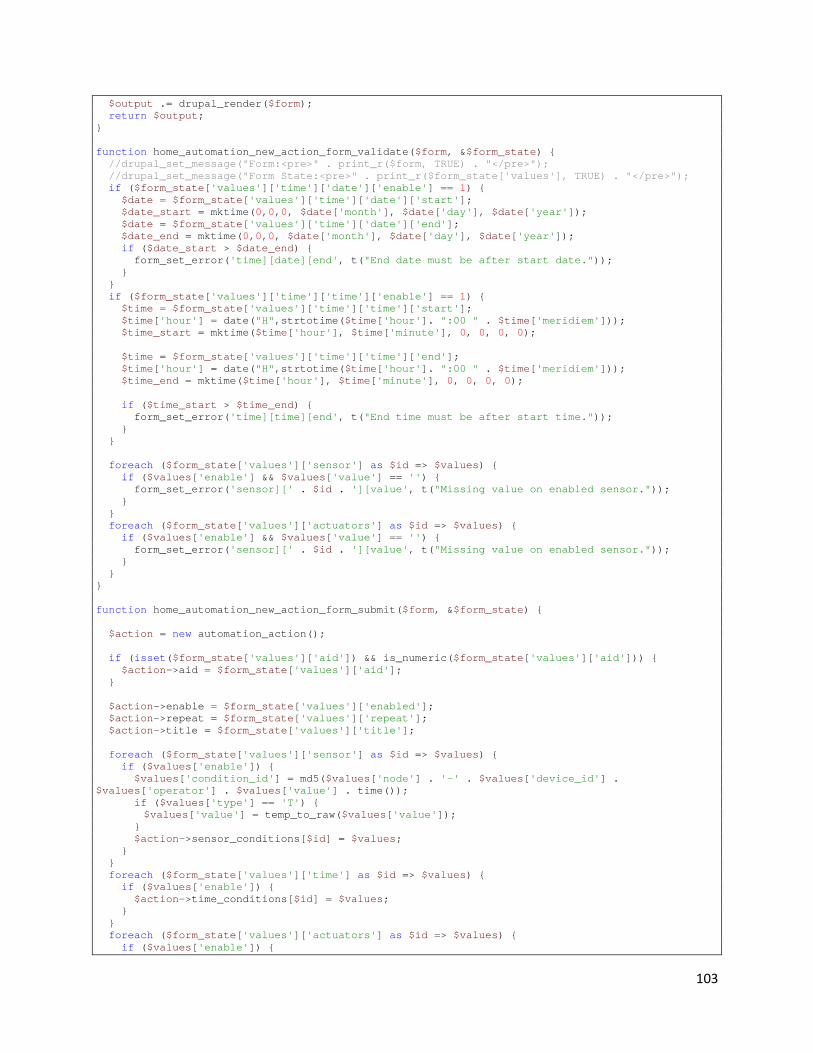
103
$output .= drupal_render($form); return $output; } function home_automation_new_action_form_validate($form, &$form_state) { //drupal_set_message("Form:<pre>" . print_r($form, TRUE) . "</pre>"); //drupal_set_message("Form State:<pre>" . print_r($form_state['values'], TRUE) . "</pre>"); if ($form_state['values']['time']['date']['enable'] == 1) { $date = $form_state['values']['time']['date']['start']; $date_start = mktime(0,0,0, $date['month'], $date['day'], $date['year']); $date = $form_state['values']['time']['date']['end']; $date_end = mktime(0,0,0, $date['month'], $date['day'], $date['year']); if ($date_start > $date_end) { form_set_error('time][date][end', t("End date must be after start date.")); } } if ($form_state['values']['time']['time']['enable'] == 1) { $time = $form_state['values']['time']['time']['start']; $time['hour'] = date("H",strtotime($time['hour']. ":00 " . $time['meridiem'])); $time_start = mktime($time['hour'], $time['minute'], 0, 0, 0, 0); $time = $form_state['values']['time']['time']['end']; $time['hour'] = date("H",strtotime($time['hour']. ":00 " . $time['meridiem'])); $time_end = mktime($time['hour'], $time['minute'], 0, 0, 0, 0); if ($time_start > $time_end) { form_set_error('time][time][end', t("End time must be after start time.")); } } foreach ($form_state['values']['sensor'] as $id => $values) { if ($values['enable'] && $values['value'] == '') { form_set_error('sensor][' . $id . '][value', t("Missing value on enabled sensor.")); } } foreach ($form_state['values']['actuators'] as $id => $values) { if ($values['enable'] && $values['value'] == '') { form_set_error('sensor][' . $id . '][value', t("Missing value on enabled sensor.")); } } } function home_automation_new_action_form_submit($form, &$form_state) { $action = new automation_action(); if (isset($form_state['values']['aid']) && is_numeric($form_state['values']['aid'])) { $action->aid = $form_state['values']['aid']; } $action->enable = $form_state['values']['enabled']; $action->repeat = $form_state['values']['repeat']; $action->title = $form_state['values']['title']; foreach ($form_state['values']['sensor'] as $id => $values) { if ($values['enable']) { $values['condition_id'] = md5($values['node'] . '-' . $values['device_id'] . $values['operator'] . $values['value'] . time()); if ($values['type'] == 'T') { $values['value'] = temp_to_raw($values['value']); } $action->sensor_conditions[$id] = $values; } } foreach ($form_state['values']['time'] as $id => $values) { if ($values['enable']) { $action->time_conditions[$id] = $values; } } foreach ($form_state['values']['actuators'] as $id => $values) { if ($values['enable']) {
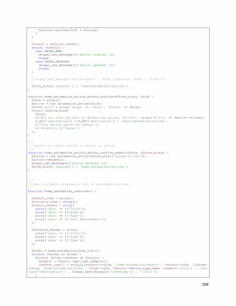
104
$action->actions[$id] = $values; } } $result = $action->save(); switch ($result) { case SAVED_NEW: drupal_set_message(t('Action created.')); break; case SAVED_UPDATED: drupal_set_message(t('Action updated.')); break; } //drupal_set_message("Action:<pre>" . Print_r($action, TRUE) . "</pre>"); $form_state['redirect'] = 'home-automation/actions'; } function home_automation_action_delete_confirm(&$form_state, $aid) { $form = array(); $action = new automation_action($aid); $form['aid'] = array('#type' => 'value', '#value' => $aid); return confirm_form( $form, t('Are you sure you want to delete the action, %title?', array('%title' => $action->title)), $_GET['destination'] ? $_GET['destination'] : 'home-automation/actions', t('This action cannot be undone.'), t('Delete'), t('Cancel') ); } /** * Handle the submit button to delete an action. */ function home_automation_action_delete_confirm_submit($form, &$form_state) { $action = new automation_action($form_state['values']['aid']); $action->delete(); drupal_set_message(t('Action deleted.')); $form_state['redirect'] = 'home-automation/actions'; } /** * Menu callback; displays a list of available devices. */ function home_automation_overview() { $sensor_rows = array(); $actuator_rows = array(); $sensor_header = array( array('data' => t('Title')), array('data' => t('Node')), array('data' => t('Type')), array('data' => t('Last Measurement')), ); $actuator_header = array( array('data' => t('Title')), array('data' => t('Node')), array('data' => t('Type')), ); $nodes = home_automation_node_list(); foreach ($nodes as $node) { foreach ($node->sensors as $sensor) { $sample = $sensor->get_last_sample(); $sensor_rows[] = array(l($sensor->title, 'home-automation/sensor/'. $sensor->sid), l($node->title, 'home-automation/node/'. $node->nid), $sensor->device_type_name, $sample['value'] . '<div class="description">' . format_date($sample['timestamp']) . '</div>'); }

105
//drupal_set_message("Actuators:<pre>" . Print_r($node->actuators, TRUE) . "</pre>"); foreach ($node->actuators as $actuator) { $actuator_rows[] = array(l($actuator->title, 'home-automation/actuator/' . $actuator->sid . '/edit'), l($node->title, 'home-automation/node/'. $node->nid), $actuator->device_type_name); } } $form = array(); $form['sensors'] = array( '#type' => 'fieldset', '#title' => t('Sensors'), '#collapsible' => TRUE, '#description' => t('A list of sensors receiving data.'), ); $form['actuators'] = array( '#type' => 'fieldset', '#title' => t('Actuators'), '#collapsible' => TRUE, '#description' => t('A list of actuators in the system.'), ); $content = theme('table', $sensor_header, $sensor_rows, array('style' => 'margin-top:0;')); //$output .= theme('pager', NULL, 25, 0); $form['sensors']['content'] = array('#value' => $content); $output = drupal_render($form['sensors']); $content = theme('table', $actuator_header, $actuator_rows, array('style' => 'margin-top:0;')); $form['actuators']['content'] = array('#value' => $content); $output .= drupal_render($form['actuators']); return $output; } function home_automation_testing($sensorID) { $sensor = new sensor($sensorID, TRUE); $sensor->load_data(); $content = "<pre>" . print_r($sensor, TRUE) . "</pre>"; foreach ($sensor->data as $timestamp => $value) { $content .= "On " . format_date($timestamp) . " recorded: " . $value . "<br/>"; } return $content; } function home_automation_view_node($nodeID) { $node = new automation_node($nodeID); drupal_set_title($node->title); $sensor_rows = array(); $actuator_rows = array(); $sensor_header = array( array('data' => t('Title')), array('data' => t('Node')), array('data' => t('Type')), array('data' => t('Last Measurement')), ); $actuator_header = array( array('data' => t('Title')), array('data' => t('Node')), array('data' => t('Type')), ); foreach ($node->sensors as $sensor) { $sample = $sensor->get_last_sample();
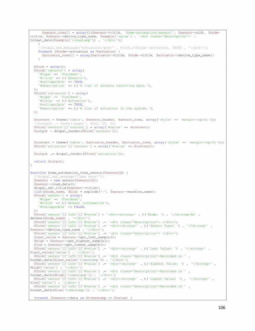
106
$sensor_rows[] = array(l($sensor->title, 'home-automation/sensor/'. $sensor->sid), $node->title, $sensor->device_type_name, $sample['value'] . '<div class="description">' . format_date($sample['timestamp']) . '</div>'); } //drupal_set_message("Actuators:<pre>" . Print_r($node->actuators, TRUE) . "</pre>"); foreach ($node->actuators as $actuator) { $actuator_rows[] = array($actuator->title, $node->title, $actuator->device_type_name); } $form = array(); $form['sensors'] = array( '#type' => 'fieldset', '#title' => t('Sensors'), '#collapsible' => TRUE, '#description' => t('A list of sensors receiving data.'), ); $form['actuators'] = array( '#type' => 'fieldset', '#title' => t('Actuators'), '#collapsible' => TRUE, '#description' => t('A list of actuators in the system.'), ); $content = theme('table', $sensor_header, $sensor_rows, array('style' => 'margin-top:0;')); //$output .= theme('pager', NULL, 25, 0); $form['sensors']['content'] = array('#value' => $content); $output = drupal_render($form['sensors']); $content = theme('table', $actuator_header, $actuator_rows, array('style' => 'margin-top:0;')); $form['actuators']['content'] = array('#value' => $content); $output .= drupal_render($form['actuators']); return $output; } function home_automation_view_sensor($sensorID) { //drupal_set_message("Came here!"); $sensor = new sensor($sensorID); $sensor->load_data(); drupal_set_title($sensor->title); list($node_name, $bla) = explode("-", $sensor->machine_name); $form['sensor'] = array( '#type' => 'fieldset', '#title' => t('Sensor Information'), '#collapsible' => FALSE, ); $form['sensor']['info']['#value'] = '<div><strong>' . t('Node: ') . '</strong>0x' . dechex($node_name) . '</div>'; $form['sensor']['info']['#value'] .= '<div class="description"> </div>'; $form['sensor']['info']['#value'] .= '<div><strong>' . t('Sensor Type: ') . '</strong>' . $sensor->device_type_name . '</div>'; $form['sensor']['info']['#value'] .= '<div class="description"> </div>'; $last_value = $sensor->get_last_sample(); $high = $sensor->get_highest_sample(); $low = $sensor->get_lowest_sample(); $form['sensor']['info']['#value'] .= '<div><strong>' . t('Last Value: ') . '</strong>' . $last_value['value'] . '</div>'; $form['sensor']['info']['#value'] .= '<div class="description">Recorded on ' . format_date($last_value['timestamp']) . '</div>'; $form['sensor']['info']['#value'] .= '<div><strong>' . t('Highest Value: ') . '</strong>' . $high['value'] . '</div>'; $form['sensor']['info']['#value'] .= '<div class="description">Recorded on ' . format_date($high['timestamp']) . '</div>'; $form['sensor']['info']['#value'] .= '<div><strong>' . t('Lowest Value: ') . '</strong>' . $low['value'] . '</div>'; $form['sensor']['info']['#value'] .= '<div class="description">Recorded on ' . format_date($low['timestamp']) . '</div>'; foreach ($sensor->data as $timestamp => $value) {

107
$data1[format_date($timestamp, "small")] = $value; } $times = array_keys($data1); $chart = array( '#chart_id' => 'light_chart', '#title' => chart_title(t('Sensor Data'), 'cc0000', 15), '#type' => CHART_TYPE_LINE, '#size' => chart_size(400, 200), '#adjust_resolution' => TRUE, '#chart_fill' => chart_fill('c', 'eeeeee'), '#grid_lines' => chart_grid_lines(20, 20, 1, 5), ); $chart['#data'][$sensor->device_type_name] = array_values($data1); $chart['#legends'][] = $sensor->device_type_name; //$chart['#data_colors'][] = '00ff00'; $chart['#data_colors'][] = 'ff0000'; $chart['#mixed_axis_labels'][CHART_AXIS_Y_LEFT][0][] = chart_mixed_axis_range_label(min(array_values($data1)), max(array_values($data1))); $chart['#mixed_axis_labels'][CHART_AXIS_X_BOTTOM][1][] = chart_mixed_axis_label($times[0]); $chart['#mixed_axis_labels'][CHART_AXIS_X_BOTTOM][1][] = chart_mixed_axis_label($times[count($times) - 1]); $chart['#mixed_axis_labels'][CHART_AXIS_X_BOTTOM][2][] = chart_mixed_axis_label(t('Time'), 50); $form['sensor']['info']['#value'] = '<div id="chart" style="float:right;">' . chart_render($chart) . '</div>' . $form['sensor']['info']['#value']; $content = drupal_render($form); // $content .= "<pre>" . print_r($sensor, TRUE) . "</pre>"; // foreach ($sensor->data as $timestamp => $value) { // $content .= "On " . format_date($timestamp) . " recorded: " . $value . "<br/>"; // } return $content; } function home_automation_add($op1, $op2) { return $op1 + $op2; } function home_automation_elements() { $type['time_field_time'] = array( '#input' => TRUE, '#process' => array('time_field_expand_time'), ); return $type; } function home_automation_notify($message) { if (variable_get('home_automation_email_notify', "") != "") { global $language; $params['message'] = $message; drupal_mail('home_automation', 'notice', variable_get('home_automation_email_notify', ""), $language, $params); return true; } return false; } function home_automation_mail($key, &$message, $params) {

108
$language = $message['language']; $variables = user_mail_tokens($params['account'], $language); switch($key) { case 'notice': $message['subject'] = t('Home Automation Notification'); $message['body'] = $params['message']; break; } } function home_automation_email_test() { home_automation_notify("Motion detected in living room!"); } function time_field_expand_time($element) { if (empty($element['#value'])) { $element['#value'] = array( 'hour' => intval(format_date(time(), 'custom', 'h')), 'minute' => intval(format_date(time(), 'custom', 'i')), 'meridiem' => format_date(time(), 'custom', 'a'), ); } $element['#tree'] = TRUE; foreach ($element['#value'] as $type => $value) { switch ($type) { case 'hour': $options = drupal_map_assoc(range(1, 12)); break; case 'minute': $options = drupal_map_assoc(range(0, 59)); break; case 'meridiem': $options = drupal_map_assoc(array('am', 'pm')); break; } if ($type == 'hour' || $type == 'minute') { foreach ($options as $option) { $options[$option] = str_pad($options[$option], 2, '0', STR_PAD_LEFT); } } $parents = $element['#parents']; $parents[] = $type; $element[$type] = array( '#type' => 'select', '#default_value' => $element['#value'][$type], '#attributes' => $element['#attributes'], '#options' => $options, ); } return $element; } function theme_time_field_time($element) { return theme('form_element', $element, '<div class="container-inline">'. $element['#children'] .'</div>'); }
Appendix C: Code for Node Software
109
Com_Protocol.c #include "Com_Protocol.h" static node_info Node; static uint16_t previous_dest; #ifdef HOST static int FileDescriptor; extern int wait_flag; #endif //#ifdef on the init_node function? //initializes the node info, node ID, number of devices, and array of sensor and actuators and an array of //type identifiers input is the where the device should get the inputs from and output is where the //output should go. If these are files they should already be open uint8_t init_node(uint16_t NodeID,uint16_t NumDevices,uint8_t* SorA ,uint8_t* DeviceType) { uint8_t i; previous_dest=HOST_ID; Node.NodeId=NodeID; Node.NumDevices=NumDevices; //set_radio_source(NodeID); //set_radio_dest(HOST_ID); if(NumDevices>NUM_DEVICES) { return COM_ERROR; } for (i=0;i<NumDevices;i++) { Node.SorA[i]=SorA[i]; Node.DeviceType[i]=DeviceType[i]; } return COM_FINE; } //------------------------------------------------------------------------------------------------------ #ifdef HOST void init_host(int file) { Node.NodeId=HOST_ID; FileDescriptor = file; set_radio_source(HOST_ID); set_radio_dest(0x0001); previous_dest=0x0001; } //------------------------------------------------------------------------------------------------------ #endif //checks to see if the host has requested to send data to the node uint8_t check_for_request(com_packet * p) { #ifdef NODE if(UDR0=='R') { send_command(C_CLEAR_TO_SEND,A_ALL,DEFAULT_DATA,HOST_ID); #ifdef DEBUG printf("Waiting for Packet\n"); #endif return get_packet(p); } #endif return NO_REQUEST; // } //------------------------------------------------------------------------------------------------------
110
#ifdef HOST //Sends the RTS packet the the specified destination may need by host to change parameters on radio void RTS(uint16_t Dest) { //Add code to check if need to change destination //change destination if we need to //fprintf(com_output,"%c",P_REQUEST_TO_SEND);//send r int n; char SendBuf[1]; sprintf(SendBuf,"%c", P_REQUEST_TO_SEND); n = write(FileDescriptor, SendBuf, 1); if (n < 0) { fputs("write() to radio failed!\n", stderr); } } #endif //------------------------------------------------------------------------------------------------------ //Sends a command void send_command(uint8_t comId,uint8_t deviceNum,uint16_t Data,uint16_t Dest) { com_packet packet; packet.Id=comId; packet.Type=P_COMMAND; packet.Device=deviceNum; packet.Data=Data; packet.Dest=Dest; send_packet(&packet); } //------------------------------------------------------------------------------------------------------ //Sends a measurement void send_measurement(uint8_t comId,uint8_t deviceNum,uint16_t Data,uint16_t Dest) { com_packet packet; packet.Id=comId; packet.Type=P_MEASUREMENT; packet.Device=deviceNum; packet.Data=Data; packet.Dest=Dest; send_packet(&packet); } void send_event(uint8_t comId,uint8_t deviceNum,uint16_t Data,uint16_t Dest) { com_packet packet; packet.Id=comId; packet.Type=P_EVENT; packet.Device=deviceNum; packet.Data=Data; packet.Dest=Dest; send_packet(&packet); } //------------------------------------------------------------------------------------------------------ void identify() { uint8_t i; //send_command(C_NUM_DEVICES,S_ALL,Node.NumDevices,HOST_ID); for (i=0;i < Node.NumDevices;i++) { send_command(C_IDENTIFY,i+1,0x0000|Node.SorA[i]<<8|Node.DeviceType[i],HOST_ID); } } //------------------------------------------------------------------------------------------------------ uint8_t node_get_p(com_packet * p)

111
{ #ifdef NODE uint8_t buffer[PACKET_LENGTH]; uint8_t i; uint8_t lastChar=0x00; uint16_t j,k; uint8_t special; k = 0; for(i=0;lastChar!=0x0D && i!=PACKET_LENGTH;i++) { for(j=0; !(UCSR0A & (1<<RXC0)) ;j++) { //if(k==0x105A) // return(BAD_PACKET); } //cli(); //while(!(UCSR0A & (1<<RXC0))); buffer[i]=UDR0; lastChar=buffer[i]; } if(i!=PACKET_LENGTH) return BAD_PACKET; else if(lastChar !=0x0D) return BAD_PACKET; //while(!(UCSR0A & (1<<RXC0))); //newLine=UDR0; //if(j==0xFFFF) //{ // send_command(C_ERROR,S_ALL,0x0004,HOST_ID); //need to clear the buffer // return BAD_PACKET; //} p->Type=buffer[0]; p->Id=buffer[1]; p->Device=buffer[2]; special=buffer[3]; if(special & 0b10000000) { buffer[4]=0x00; } else if(special & 0b01000000) { buffer[4]=0x0D; } if(special & 0b00100000) { buffer[5]=0x00; } else if(special & 0b00010000) { buffer[5]=0x0D; } p->Data=buffer[4]<<8|buffer[5]; p->Source=0x0000|(buffer[8]<<8)|buffer[9]; p->Dest=0x0000|(buffer[6]<<8)|buffer[7]; if(special & 0b10000000) if(((buffer[9]<<8)|buffer[10])!= Node.NodeId) { return PACKET_NOT_FOR_ME; } #endif return PACKET_FOR_ME; } //------------------------------------------------------------------------------------------------------ void get_node_info(node_info * N) { uint8_t i; N->NodeId=Node.NodeId;
112
N->NumDevices=Node.NumDevices; for(i=0;i<Node.NumDevices;i++) { N->SorA[i]=Node.SorA[i]; N->DeviceType[i]=Node.DeviceType[i]; } } //------------------------------------------------------------------------------------------------------ //send the specified packet void node_send_p(com_packet * p) { /* unit8_t Id; unit8_t Type; unit8_t Device; unit16_t Data; unit16_t Dest; */ uint8_t upperbyte; uint8_t lowerbyte; uint8_t special=0x0F; upperbyte=p->Data>>8; lowerbyte= (char) p->Data; if(upperbyte==0x00) { special|=0b10000000; upperbyte='G'; } else if (upperbyte==0x0D) { special|=0b01000000; upperbyte='G'; } if(lowerbyte==0x00) { special|=0b00100000; lowerbyte='G'; } else if (lowerbyte==0x0D) { special|=0b00010000; lowerbyte='G'; } //printf("%c%c",lowerbyte,upperbyte); printf("%c%c%c%c%c%c%c%c%c%c%c", p->Type, p->Id, p->Device, special, upperbyte, lowerbyte, (p->Dest>>8)|0x00, p->Dest|0x00, (Node.NodeId>>8)|0x00, Node.NodeId, 0x0D); } //------------------------------------------------------------------------------------------------------ //send the specified packet #ifdef HOST void host_send_p(com_packet * p) { int n; char SendBuf[9]; sprintf(SendBuf,"%c%c%c%c%c%c%c%c%c%c", p->Type, p->Id, p->Device,
113
(p->Data>>8)|0x00, p->Data|0x00, (p->Dest>>8)|0x00, p->Dest|0x00, (Node.NodeId>>8)|0x00, Node.NodeId|0x00, 0x0D); if(p->Dest!=previous_dest) { if(SUCCESS!=set_radio_dest(p->Dest)) printf("Error Changing Radio Dest\n"); else previous_dest=p->Dest; } n = write(FileDescriptor, SendBuf, 9); if (n < 0) { fputs("write() to radio failed!\n", stderr); } } //--------------------------------------------------------------------------------------------------- unsigned int host_get_p(com_packet * p) { unsigned char buffer[PACKET_LENGTH]; int i; for(i=0;i<PACKET_LENGTH;i++) { buffer[i]=fgetc(stdin); } p->Type=buffer[0]; p->Id=buffer[1]; p->Device=buffer[2]; p->Data=buffer[3]<<8|buffer[4]; p->Source=buffer[7]<<8|buffer[8]; if(((buffer[7]<<8)|buffer[8])!= Node.NodeId) { return PACKET_NOT_FOR_ME; } return PACKET_FOR_ME; } #endif int set_radio_dest(uint16_t DestID) { char out_buffer[10]; if(SUCCESS!=send_AT("+++",3))//start command mode return FAILURE; sprintf(out_buffer,"ATDL%u",DestID); if(SUCCESS!=send_AT(out_buffer,6));//set source address return FAILURE; if(SUCCESS!=send_AT("ATAC",4));//apply changes return FAILURE; if(SUCCESS!=send_AT("ATCN",4));//exit command mode return FAILURE; return SUCCESS; } uint8_t node_send_AT(uint8_t * Com,uint8_t length) { uint8_t i,time_out; uint8_t buffer[3]; for(i=0;i<length;i++) { loop_until_bit_is_set(UCSR0A, UDRE0); UDR0 = Com[i]; //exit command mode } i=0; time_out=0; buffer[0]=0x00; buffer[1]=0x00;

114
for(i=0;i<3;i++) { while(!(UCSR0A & (1<<RXC0))&&time_out<0xFFFF) { time_out++; } if(time_out==0xFFFF) return FAILURE; buffer[i]=UDR0; time_out=0; } if( !(buffer[0]=='O' && buffer[1]=='K')) { return FAILURE; } return SUCCESS; } #ifdef HOST int host_send_AT(unsigned char * Com, int length) { char buffer[3]; unsigned int time_out=0; int n; n=write(FileDescriptor,Com,length); if(n<0) { printf("Error Sending Command"); } for (time_out=0;wait_flag==TRUE && time_out<0xFFFFFFFF;time_out++); if(time_out==0xFFFFFFFF) { //printf("Time out while sending command to radio\n"); return FAILURE; } read(FileDescriptor,buffer,3); if( !(buffer[0]=='O' && buffer[1]=='K')) { return FAILURE; } return SUCCESS; } #endif uint8_t set_radio_source(uint16_t NodeID) { char out_buffer[10]; if(SUCCESS!=send_AT("+++",3))//start command mode return FAILURE; sprintf(out_buffer,"ATMY%u",NodeID); if(SUCCESS!=send_AT(out_buffer,6));//set source address return FAILURE; if(SUCCESS!=send_AT("ATAC",4));//apply changes return FAILURE; if(SUCCESS!=send_AT("ATCN",4));//exit command mode return FAILURE; return SUCCESS; }
Functions.c #include "Functions.h"

115
short lightread() { return adc_read(0); } short tempread() { return adc_read(1); } void sleep(double sec) { double maxms, last; int sleeps; sec *= 1000.0; /* turn seconds into milliseconds */ maxms = 262144000 / F_CPU; sleeps = sec / maxms; last = sec - (sleeps * maxms); while (sleeps--) _delay_ms(maxms); _delay_ms(last); return; } void adc_init() { /* internal pull-ups interfere with the ADC. disable the * pull-up on the pin if it's being used for ADC. either * writing 0 to the port register or setting it to output * should be enough to disable pull-ups. */ PORTC = 0x00; DDRC = 0x00; /* unless otherwise configured, arduinos use the internal Vcc * reference. MUX 0x0f samples the ground (0.0V). */ ADMUX = _BV(REFS0) | 0x0f; /* * Enable the ADC system, use 128 as the clock divider on a 16MHz * arduino (ADC needs a 50 - 200kHz clock) and start a sample. the * AVR needs to do some set-up the first time the ADC is used; this * first, discarded, sample primes the system for later use. */ ADCSRA |= _BV(ADEN) | _BV(ADPS2) | _BV(ADPS1) | _BV(ADPS0) | _BV(ADSC); /* wait for the ADC to return a sample */ loop_until_bit_is_clear(ADCSRA, ADSC); } unsigned short adc_read(unsigned char pin) { unsigned char l, h, r; //PORTB = PORTB | 0b00000011; r = (ADMUX & 0xf0) | (pin & 0x0f); ADMUX = r; /* select the input channel */ ADCSRA |= _BV(ADSC); loop_until_bit_is_clear(ADCSRA, ADSC); /* must read the low ADC byte before the high ADC byte */ l = ADCL; h = ADCH; //PORTB = 0x00; return ((unsigned short)h << 8) | l; }
MotionNode.c //This contains the main entry point of the program and here is where the code of each node differs slightly. #include "Functions.h" #define NUM_DEVICES 6
116
#define NODE_ID 0x6E6E #include "Com_protocol.h" #define FOSC 8000000 #define BAUD 9600 #define MYUBRR FOSC/16/BAUD-1 #define motionread() lightread() static int cput(char c, FILE *f); static int uart_putchar(char c, FILE *stream); uint8_t uart_getchar(void); void init(); void inter(); #define FULL_COUNT 250 #define COUNT_TO OCR1A #define TIMER_REG TCCR1B #define T_OFF 0x00 #define T_ON (_BV(WGM12) | _BV(CS12)) static FILE mystdout = FDEV_SETUP_STREAM(uart_putchar, NULL, _FDEV_SETUP_WRITE); int glob = 0; int timey = 0; int percent = 100; int timer_done = 1; int duct_state = 1; short motion; //{percent on, divide timer by int dimmer_lookup[11][2] = { {0,0} , {10,3510}, {20,3120} , {30,2730} , {40,2340}, {50,1950} , {60,1560} , {70,1170}, {80,780},{90,390},{100,1} }; void open_duct() { if(duct_state == 6) { } else { PORTB = 0b00000010; sleep(1); for(int i = 0; i < 0xff; i++) { } PORTB = 0b00000000; duct_state = 1; } } void close_duct() { if(duct_state == 6) { } else { PORTB = 0b00000001; sleep(1); for(int i = 0; i < 0xff; i++) { } PORTB = 0b00000000; duct_state = 0; } } void switchon(uint8_t device) { uint8_t temp; temp = PORTB; switch(device) { case 3: PORTB = temp & 0b11101111; break; case 4:

117
PORTB = temp & 0b11011111; break; case 5: PORTB = temp & 0b10111111; break; case 6: PORTB = temp & 0b01111111; break; default: break; } } void switchoff(uint8_t device) { uint8_t temp; temp = PORTB; switch(device) { case 3: PORTB = temp | 0b00010000; break; case 4: PORTB = temp | 0b00100000; break; case 5: PORTB = temp | 0b01000000; break; case 6: PORTB = temp | 0b10000000; break; } } void set_dimmer(); short sample_int = 10; uint8_t SorA[NUM_DEVICES]={'S','S','A','A','A','A'}; uint8_t Devices[NUM_DEVICES]={S_TEMP,S_MOTION,A_SWITCH,A_SWITCH,A_SWITCH,A_SWITCH}; uint8_t packet_ok; uint8_t RX_ready = 0; short raw; int times = 0; int main (void) { com_packet Packet; //PCICR = 0b00000100; //PCMSK2 = 0b00000001; //SMCR = 0x00000001;//enables sleep mode init(); inter(); adc_init(0); sei(); //set_dimmer(); TIMER_REG = T_ON; //get it turned on. //lightread(); //close_duct(); if(COM_FINE!=init_node(NODE_ID,NUM_DEVICES,SorA,Devices)) { printf("Error Initializing Device\r"); while(1); } times++; com_packet* p; p = &Packet; send_command(C_ACK,0xFF,DEFAULT_DATA,HOST_ID); //send_packet(&Packet); while (1) { /*sleep(1); PCICR = 0b00000100; sleep(1);

118
PCICR = 0b00000100; RX_ready = 1;*/ //SMCR = 0x00000001; //asm("SLEEP"); packet_ok = get_packet(&Packet); if( BAD_PACKET!=packet_ok && (Packet.Dest == NODE_ID || Packet.Dest == BROADCAST)) { switch (Packet.Type) { case P_COMMAND: switch (Packet.Id) { case C_SET_SAMPLE_RATE: { //printf("Recieved Set Sample Rate Command Device:%d Rate: %d From:%X\n",Packet.Device,Packet.Data,Packet.Source); sample_int = Packet.Data; //send_packet(&Packet); } break; case C_QUERY: //printf("Recieved Query Command Device:%d Data: %d From:%X\n",Packet.Device,Packet.Data,Packet.Source); //printf("Identifying\n"); identify(); break; case C_OFF: //actuator switchoff(Packet.Device); //send_packet(&Packet); break; case C_ON: //actuator switchon(Packet.Device); //send_packet(&Packet); break; case C_SET: //Set a value ... ie dimmer //send_packet(&Packet); percent = Packet.Data; set_dimmer(); break; default: //send_command(C_ERROR,Packet.Device,0x0000,HOST_ID); break; }//command switch break; case P_MEASUREMENT: //send_packet(&Packet); break; default: //printf("Unknown Packet Type\n"); //send_command(C_ERROR,Packet.Device,0x0000,HOST_ID); break; }//packet type switch send_command(C_ACK,Packet.Device,DEFAULT_DATA,HOST_ID); }//if }//while return 0; } void set_dimmer() { int i; for(i = 0; i < 11; i++) {

119
if(percent == dimmer_lookup[i][0]) { COUNT_TO = dimmer_lookup[i][1]; } } } void inter() { //TCCR1A = 0x00; //TCCR1B = (_BV(WGM12) | _BV(CS12)); TCCR1A = _BV(WGM01); TCCR1B = (_BV(CS00) | _BV(CS02)); TIMER_REG = T_OFF; COUNT_TO = 7812; //was 505 TIMSK1 = _BV(OCIE1A); EICRA = 0x0f;//these are external interrupt register EIMSK = 0x01; } void init() { UBRR0H = (MYUBRR >> 8); UBRR0L = MYUBRR; UCSR0B = (1<<RXEN0)|(1<<TXEN0); stdout = &mystdout; DDRB = 0xff; /* there are some LEDs connected to PORTB */ PORTB = 0xff; } ISR(TIMER1_COMPA_vect) { timey++; //timey was 60 if(timey > 59*sample_int) { raw = tempread(); send_measurement(M_TEMP,1,raw,HOST_ID ); //printf("temp value: %d\n",raw); //PORTB ^= 0x00; //printf("%d seconds\n",glob); //glob++; timey = 0; timer_done = 1; //TIMER_REG = T_OFF; } } ISR(TIMER1_OVF_vect) { printf("overflow2\n"); } ISR(PCINT2_vect) { } ISR(INT0_vect) { //printf("motion.... I mean it!!\n"); //send_measurement(M_TEMP,1,1,HOST_ID );t send_event(M_MOTION,2,1,HOST_ID); /* if(timer_done == 1) { //PORTB = 0xFF; TIMER_REG = T_ON;

120
printf("in here4!!\n"); timer_done = 0; } */ } static int cput(char c, FILE *f) { loop_until_bit_is_set(UCSR0A, UDRE0); UDR0 = c; return 0; } static int uart_putchar(char c, FILE *stream) { if (c == '\n') uart_putchar('\r', stream); loop_until_bit_is_set(UCSR0A, UDRE0); UDR0 = c; return 0; } uint8_t uart_getchar(void) { while( !(UCSR0A & (1<<RXC0)) ); return(UDR0); }
Com_Protocol.h //Comm Protocol.h #ifndef COMM_PROTOCOL_H #define COMM_PROTOCOL_H #define BROADCAST 0xFFFF #include <stdio.h> #define PACKET_LENGTH 11 //#define HOST //Change to HOST if building for the host //#define DEBUG #define NODE #define NUM_DEVICES 6 //#defines for function return values #define COM_FINE 0 #define COM_ERROR 1 #define PACKET_NOT_FOR_ME 2 #define PACKET_FOR_ME 3 #define NO_REQUEST 4 #define BAD_PACKET 5 #define SUCCESS 6 #define FAILURE 7 #ifdef HOST //#define uint8_t unsigned char //#define uint16_t unsigned short #include "common.h" #define send_packet host_send_p #define get_packet host_get_p #define send_AT host_send_AT //#include <fstream> #else #define send_packet node_send_p #define get_packet node_get_p #define send_AT node_send_AT #include <avr/io.h> #endif #define HOST_ID 0xff01 //#defines for types of packets #define P_COMMAND 'C' #define P_MEASUREMENT 'M'

121
#define P_REQUEST_TO_SEND 'R' #define P_EVENT 'E' //#defines for command that can be sent #define C_OFF 'F' #define C_ON 'O' #define C_SET_SAMPLE_RATE 'R' #define C_CLEAR_TO_SEND 'C' #define C_QUERY 'Q' #define C_NEED_TO_IDENTIFY 'N' #define C_DONE 'D' #define C_ERROR 'E' #define C_NUM_DEVICES 'U' #define C_IDENTIFY 'I' #define C_SET 'S' #define C_REQUEST_MEASUREMENT 'M' #define C_ACK 'A' //#defines for measurements that can be sent #define M_TEMP 'T' #define M_MOTION 'M' #define M_BUTTON 'B' #define M_LIGHT 'L' #define M_CURRENT 'C' //#defines for sensor types that can be sent #define S_LIGHT 'L' #define S_TEMP 'T' #define S_CURRENT 'C' #define S_SWITCH 'S' #define S_MOTION 'M' #define S_ALL 'A' //#defines for actuator types that can be sent #define A_VAR_SWITCH 'V' #define A_DUCT 'D' #define A_SWITCH 'S' #define A_EMAIL 'E' #define A_ALL 'A' #define DEFAULT_DATA 0x4444 typedef struct com_packet_ { uint8_t Id; uint8_t Type; uint8_t Device; uint16_t Data; uint16_t Dest; uint16_t Source; }com_packet; typedef struct node_info_ { uint16_t NodeId; uint16_t NumDevices; uint8_t DeviceType[NUM_DEVICES]; uint8_t SorA[NUM_DEVICES]; }node_info; uint8_t init_node(uint16_t,uint16_t,uint8_t*,uint8_t*); void send_packet(com_packet *); uint8_t check_for_request(com_packet *); void send_command(uint8_t,uint8_t,uint16_t,uint16_t); void send_measurement(uint8_t, uint8_t, uint16_t, uint16_t); void send_event(uint8_t, uint8_t, uint16_t, uint16_t); void identify(); uint8_t node_get_packet(com_packet *);

122
unsigned int host_get_p(com_packet * ); void node_send_p(com_packet * ); uint8_t node_get_p(com_packet *); void get_node_info(node_info * ); uint8_t set_radio_source(uint16_t NodeID); int set_radio_dest(uint16_t DestID); uint8_t node_send_AT(uint8_t * Com,uint8_t length); int host_send_AT(unsigned char * Com, int length); #ifdef HOST void init_host(int); void RTS(uint16_t); void host_send_p(com_packet * ); #endif #endif
Functions.h #include <avr/io.h> #include <stdio.h> #include <avr/interrupt.h> #include <avr/pgmspace.h> #include <util/delay.h> void sleep(double sec); unsigned short adc_read(unsigned char pin); void adc_init(); short lightread(); short tempread();