scientific experiments contingency planning and procedures
TRANSCRIPT

:::::::::::::::::::::::
~fffffj~ :::::::::::::::::::::::
j)j)}J}j j]j]j]j]j]j]j]j]j]j]j]j
~ ~ ~ ~ ~ ~ j j j j j j ~ j j j j j j \ ~ j j ::::::::::::::::::::::: ·:·:·:·:·:·:·:·:·:·:·:· :·:·:-:-:·:·:·:·:·:·:·: ::::::::::::::::::::::: : ~: ~: ~: ~: ~: ~: ~: ~: ~ =~: ~: :-:·:·:·:·:·:·:·:·:·:·: ·:-:·:·:·:·:·:·:·:·:-::-:·:·:·:·:·:·:·:·:·:·: .·.·.·.·.·.·.·.·.·.·.·.
tttt?I .·.·.·.·.·.·.·.·.·.·.·. :~::: ::::::::::::::::::
MSC-04105
NATIONAL AERONAUTICS AND SPACE ADMINISTRATION
SCIENTIFIC EXPERIMENTS CONTINGENCY PLANNING AND PROCEDURES
MISSION J-1 I APOLLO 15
FINAL
MANNED SPACECRAFT CENTER HOUSTON,TEXAS
June 1, 1971
Revised July 12, 1971
MSC FORM 2026A (REV MAY 68}


MSC-04105
NATIONAL AERONAUTICS AND SPACE ADMINISTRATION
SCIENTIFIC EXPERIMENTS CONTINGENCY PLANNING AND PROCEDURES
MISSION J-1/APOLLO 15
FINAL
Manned Spacecraft Center
Houston, Texas
June 1, 1971
Revised July 12, 1971


REPLY TO
NATIONAL AERONAUTICS AND SPACE ADMINISTRATION MANNED SPACECRAFT CENTER
HOUSTON, TEXAS 77058
ATTN OF: TD5
MEMORANDUM
TO: See Distribution
FROM: TA/Deputy Director of Science and Applications
SUBJECT: Scientific Experiments Contingency Planning and Procedures, Mission J-1/Apollo 15
This change notice is revision A and should be incorporated into the basic document dated June 1, 1971, according to the change instructions sheet enclosed. Incorporation of revision A will make this document current as of July 12, 1971.
Comments regarding the Scientific Experiments Contingency Planning and Procedures document ;f-or Mission J-1/Apollo 15 should be directed to the Sgierl~e Requirements and Operations Branch (TD5), Manned Spacecraft Cknter, Houston, /Texas 77058.
( ! / / i t~ ///
\ . . I.. . ''···y,iC/
)' (J};;tt/' 'lt:/rt.ii/.-.\ /J arne'¥ A. /IJ<S:v~l )
! I / , ;
· ·-Errcj!osm.e )·-·---_..~ I I
I ./
Enclosure
SCIENTIFIC EXPERIMENTS CONTINGENCY PLANNING AND PROCEDURES
MISSION J-1/APOLLO 15
CHANGE INSTRUCTION SHEET
Update the Scientific Experiments Contingency Planning and Procedures Document for Mission J-1/Apollo 15 with the following instructions.
Remove and replace the following changed pages:
Page 3
Page 4
Remove the following pages:
Page 6
Page 7
Page 8
Page 9
Page 10
Page 11
Page 12
Add the following new pages:
Page 6 Page 8.5 Page 9· 5
Page 7 Page 8.6 Page 9.6
Page 7-1 Page 8.7 Page 9-7
Page 7-2 Page 8.8 Page 9.8
Page 7-3 Page 8.9 Page 10
Page 7.4 Page 8.10 Page 11
Page 7-5 Page 8.11 Page 12.1
Page 7.6 Page 8.12 Page 12.2
Page 7·7 Page 8.13 Page 12.3
Page 8 Page 9 Page 12.4
Page 8.1 Page 9.1 Page 12.5
Page 8.2 Page 9.2 Page 12.6
Page 8.3 Page 9·3 Page 8.4 Page 9.4
SCIENTIFIC EXPERIMENTS CONTINGENCY PLANNING AND PROCEDURES
MISSION J-1/APOLLO 15
Prepared f'or the
Science Requirements and Operations Branch Science Missions Support Division
Science and Applications Directorate Manned Spacecraf't Center
Houston, Texas
FINAL
Prepared by: ..c:;JL.,., ~~ Glenn P. Barnes
Approved b~~ J:R:Ba£;rs- ~·
Space Experiments Engineering General Electric Company
Experiments Operations Section
Any comme s or questions on this document should be f'orwarded to J. R. Bates or G. P. Barnes, Science Requirements and Operations Branch, TD5, extension 5851 or 5028.


SECTION
l.O
1.1
1.2
1.3
1.4
1.5
APPENDIX
TABLE OF CONTENTS
PAGE NO.
GENERAL 1
ASS~TIONS. . . . . . . . . . . . . . . . . . . . . . . . . . . . . . . . . . l
TIME CONSTRAINT. . . . • . • . • . . . . . . . • . . • . . . . . . . . . . 1
HOLD POINTS . . . . • . . • . . • • . • • . . • . . . . . . • . . . . . . • . . 1
EXPERIMENT RESCHEDULING...................... 3
EXPERIMENT PRIORITIES........................ ·3
ABBREVIATIONS AND ACRONYMS . . . • • . . . . • • • . • • . . . . A -1
iii

TABLES
TABLE NO. PAGE
NUMBER
1 SCIENCE DATA RETURN MATRIX FOR ALTERNATE MISSIONS 5
2 EXTRA-VEHICULAR ACTIVITY (EVA) DECISIONS.......... 6
3 MODULARIZED EQUIPMEN'I' STORAGE ASSEMBLY (MESA) 13 DEPLO'Th1:EN:[l • • . • . . • • • • • • • • . • • • . • . • • • • • • . • • • • • . • . ••••
4 APOLLO LUNAR HAND TOOLS ...••••..•.•.•••••••.••.•.• 17
5 CA11:ERAS . • . . . . . . . . • . . • . . . . • . . . . . . . . . . . . . . . . . . . . . . . . 21
6 SOLAR WIND COMPOSITION EXPERIMEN'I' ••••••••.••.••••• 22
7 LASER RANGING RETRO-REFLECTOR EXPERIMEN'I' •••.••••.• 24
8 ALSEP OFFLOAD. . • • • • • . . • . • • . • . • • • • • . • . • . . • . . • • • . • • . 2 9 8.1 SE!Q Bay Door. . . . . . . . . . . . . • . • . . . . . . . . • . . . . . . . . 29 8.2 Subpackage Removal by Boom •••.•.••••••••••.•. 31 8.3 Manual Subpackage Removal •.••.•.••••••.•••••. 34
9 RTG FUELING. . . . . . . . . . . . . . . . • . . . . . . . . . . . . . . . . . . . . . . 36
10 ALSEP TRAVERSE ••••••••••••••••••••• '. • • • • • . • • . . . . • • 45
11 SUBPALLET REMOVAL. . • • . • . • • . • . • . • . . • • . • . • • . • • • • . • • . 50
12 RTG CABLE INTERCONNECT. • . . • • • • • . • • • • • • . • . • • . • • • • • • 58
13 PASSIVE SEISMIC EXPERIMEN'I' ••.•.•..•.••••..•••••.•• 65
14 HEAT FLOW EXPERIMENT ••••••••••••.••.•.••••••••••.• 70 14.1 Deployment.................................. 70 14. 2 Drill Operations. • • • • • • • • . . • . • . • • • • . . • . • . • • . 81 14.3 Probe Emplacement........................... 90 14.4 Core Operations............................. 94
15 LUNAR SURFACE MAGNETOMETER EXPERIMEN'I'. • • . . • . • • • • • • 98
16 SUPRAT.HERMAL ION DETECTOR EXPERIMEN'I'/COLD CATHODE 103 GAUGE EXPERIMEN'I'. • • • . • • • • • • • . • . • • • • • • • • • . • . • • • • • . •
17 SOLAR WIND SPECTROMETER EXPERIMENT ..••.•.•..•.•.•• 114
iv
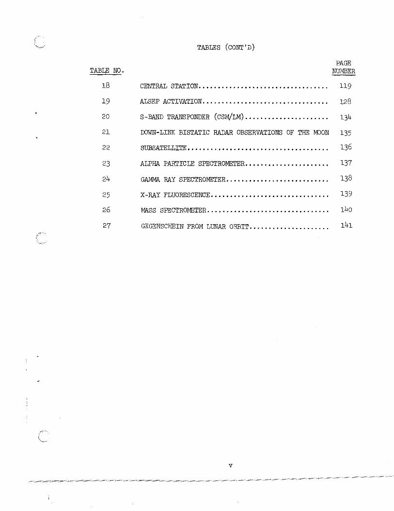
TABLES ( CONT 'D)
TABLE NO. PAGE
NUMBER
18 CENTRAL STATION. . . • . . . . . . . . . . . . . . . . . . . . . . . . . . . . . . 119
19 ALSEP ACTIVATION. . . . . . . • . . . . . . . . • . . . . . . . . . . . . . . . . 128
20 S-BAND TRANSPONDER (CSM/LM)...................... 134
21 DOWN-LINK BISTATIC RADAR OBSERVATIONS OF THE MOON 135
22 SUBSATELLITE". . . . • . . . • • . • . . . . • . . . . . . . . . . . . . . . . . . . . 136
23 ALPHA PARTICLE SPECTROMETER...................... 137
24 GAMMA RAY SPECTROMETER........................... 138
25 X-RAY FLUORESCENCE. . . . . . . . . . . . . . . . . . . . . . . . . . . . . . . 139
26 MASS SPECTROMETER. . . . . . . . . . . . . . . . . . . . . . . . . . . . . . . . 140
27 GEGENSCHEIN FROM LUNAR ORBIT..................... 141
v

ILLUSTRATIONS
Contingency Deployment Pattern for Heat Flow Experiment • . . . . . . . . . . . . . .
vi
Figure Number
1
Page Number
So

SCIENTIFIC EXPERIMENTS CONTINGENCY PLANNING AND PROCEDURES
MISSION J-1/APOLLO 15
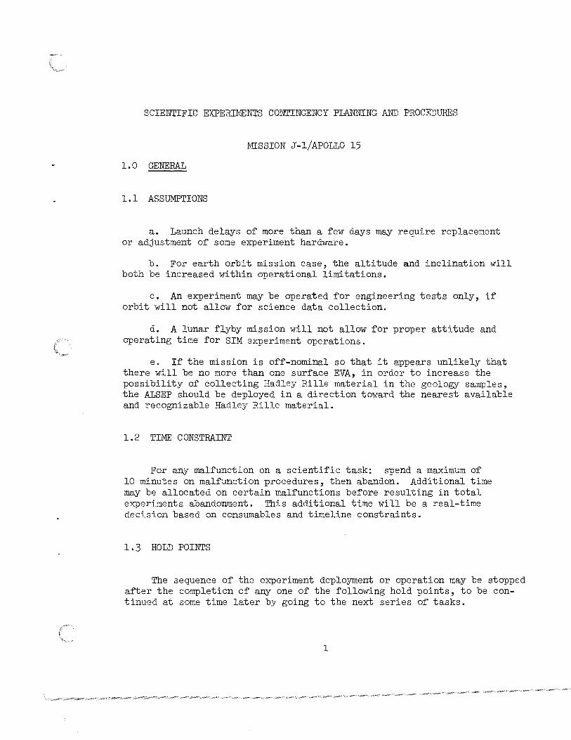
1.0 GENERAL
1.1 ASSUMPTIONS
a. Launch delays of more than a few days may require replacement or adjustment of some experiment hardware.
b. For earth orbit mission case, the altitude and inclination will both be increased within operational limitations.
c. An experiment may be operated for engineering tests only, if orbit will not allow for science data collection.
d. A lunar flyby mission will not allow for proper attitude and operating time for SIM experiment operations.
e. If the mission is off-nominal so that it appears unlikely that there will be no more than one surface EVA, in order to increase the possibility of collecting Hadley Rille material in the geology samples, the ALSEP should be deployed in a direction toward the nearest available and recognizable Hadley Rille material.
l. 2 TIME CONSTRAINT
For any malfunction on a scientific task: spend a maximum of 10 minutes on malfunction procedures, then abandon. Additional time may be allocated on certain malfunctions before resulting in total experiments abandonment. This additional time will be a real-time decision based on consumables and timeline constraints.
1. 3 HOLD POINTS
The sequence of the experiment deployment or operation may be stopped after the completion of any one of the following hold points, to be continued at some time later by going to the next series of tasks.
l
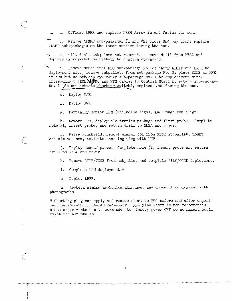
a. Offload LRRR and emplace LRRR Array in and facing the sun.
b. Remove ALSEP sub-packages #l and #2; close SEQ bay door; emplace ALSEP sub-packages on the lunar surface facing the sun.
~ c. Tilt fuel cask; dome not removed. Remove drill from MESA and depress microswitch on battery to confirm operation.
d. Remove dome; fuel RTG sub-package No. 2; carry ALSEP and LRRR to deployment site; remove subpallets from sub-package No. 2; place SIDE or HFE in sun but do no~d~oy, carry sub-package No. l to emplacement site, interconnect SIDE,~~' and RTG cables to Central Station, rotate sub-package No. l (do not actuate shorting switch), emplace LRRR facing the sun. ,. -......
e. Deploy PSE.
f. Deploy SWS.
g. Partially deploy LSM (including legs), and rough sun align.
h. Remove HFE, deploy electronics package and first probe. Complete hole #1, insert probe, and return drill to MESA and cover.
i. Raise sunshield; remove gimbal box from SIDE subpallet, mount and aim antenna, activate shorting plug with UHT.
j. Deploy second probe. Complete hole #2, insert probe and return drill to MESA and cover.
k. Remove SIDE/CCGE from subpallet and complete SIDE/CCGE deployment.
l. Complete LSM deployment.*
m. Deploy LRRR.
n. Recheck aiming mechanism alignment and document deployment with photographs.
* Shorting plug can apply and remove short to RTG before and after experiment deployment if deemed necessary. Applying short is not recommended since experiments can be commanded to standby power OFF so no hazard would exist for astronauts.
2

1.4 EXPERIMENT RESCHEDULING
In the event of a change in mission profile, e.g., no TLI capability-earth orbit only, deployment and operation of non-lunar surface experiments will be affected. Table 1 shows which experiments may be scheduled for alternate missions. Lunar surface experiments are covered in Tables 2 through 19. Lunar orbit experiments are covered in Tables 20 through 27.
Experiments should be exercised during any alternate mission to verify hardware operation and to evaluate procedures.
1.5 EXPERIMENT PRIORITIES
Mission priorities for Lunar Surface Experiments Deployment, Orbital Photography and Lunar Geology Investigation are defined as follows:
PRIORITY
l.
2.
3.
4.
5.
6.
7.
8.
LUNAR SURFACE ACTIVITIES
OBJECTIVE/EXPERIMENT
Contingency Sample Collection
Documented Samples at Apennine Front
Apollo 15 ALSEP
• HFE • LSM • PSE • CCGE • sws • SIDE • Lunar Dust Detector
Drill Core Sample
Laser Ranging Retro-Reflector
Lunar Geology Investigations
Solar Wind Composition
Soil Mechanics
3

1.5 (CONT'D)
PRIORITY
l.
2.
3.
4.
5-
6.
7.
8.
9-
10.
ll.
LUNAR ORBITAL ACTIVITIES
OBJECTIVE/EXPERIMENT
Gamma-Ray Spectrometer
X-Ray Fluorescence
SM Orbital Photographic Tasks
Subsatelli te
• Particle Shadows/Boundary Layer
• Magnetometer
• S-Band Transponder
Bistatic Radar
S-Band Transponder (CSM/LM)
Alpha Particle Spectrometer
Mass Spectrometer
UV Photography - Earth and Moon
Gegenschein from Lunar Orbit
CM Photographic Tasks
4
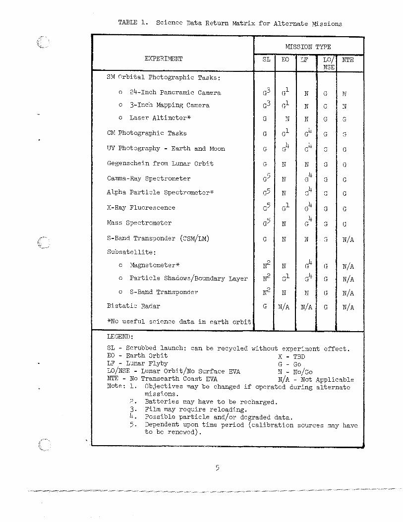
TABLE l. Science Data Return Matrix for Alternate Missions
MISSION TYPE
SL EO LF LO/ NTE i NSE
EXPERIMENT
SM Grbital Photographic Tasks:
o 24-Inch Panoramic Camera
o 3-Inch Mapping Camera
o Laser Altimeter*
CM Photographic Tasks
UV Photography - Earth and Moon
Gegenschein from Lunar Orbit
Gamma-Ray Spectrometer
Alpha Particle Spectrometer*
X-Ray Fluorescence
Mass Spectrometer
S-Band Transponder (CSM/LM)
Sub satellite:
o Magnetometer*
o Particle Shadows/Boundary Layer
o S-Band Transponder
Bistatic Radar
*No useful science data in earth orbit
LEGEND:
G
G
N
G N
N
N
N
G
G
G
G
G
G
G
G
G
G
G
G
G
G
G N/A N/A, G
N
N
G
G
G
G
G
G
G
G
N/A
N/A
N/A
N/A
N/A
SL - Scrubbed launch: can be recycled without experiment effect. EO - Earth Orbit X - TBD LF - Lunar Flyby LO/NSE - Lunar Orbit/No Surface EVA NTE - No Transearth Coast EVA Note: 1. Objectives may be changed if
missions.
G - Go N - No/Go N/A - Not Applicable
operated during alternate
2. Batteries may have to be recharged. 3. Film may require reloading. 4. Possible particle and/or degraded data. 5. Dependent upon time period (calibration sources may have
to be renewed).
5

TABLE 2. EVA DECISIONS
TABLE 2. 1 - OFF NOMINAL EVA PLANNING
TABLE 2. 2 - OFF NOMINAL LANDINGS
TABLE 2. 3 - DELAYED EVA TIMELINES
TABLE 2. 4 - EVA WALKING TRAVERSE
6

TABLE 2. EVA DECISIONS
TABLE 2 .1 - OFF NOMINAL EVA PLANNING
7

-.;j
1-'
EVENT NO.
l.
TABLE 2. EVA Decisions
TABLE 2 .1 - OFF NOMINAL EVA PLANNING
CONTINGENCY AGENT ACTION REMARKS
Crew unable to locate touch- Crew Make visual observatio~s ··and down point in the landing describe features_..a-roi.md the ellipse. LM. . .. /
MCC l. Compare television images and the astronauts' de scrip-tion of features to the over-all features in the map package.
MCC/ 2. Revise ALSEP deployment Crew and traverse plans as required

--.::]
fD
EVENT NO.
2.
.;t-
TABLE 2. EVA Decisions (Cont'd)
TABLE 2 .1 - OFF NOMINAL EVA PLANNING
CONTINGENCY AGENT ACTION REMARKS
Not enough time for EVA. Crew Make careful observations and descriptions of surface through LM windows. Numerous still camera photos should be taken with both black and white and color films from both windows. Photos with polarizing filter in three different positions should be made.
'
MCC Study landing area on maps and submit pertinent questions relating to surface smoothness or roughness, the contours of surface size of rocks and craters in area.

,. f
TABLE 2. EVA Decisions (Cont'd)
TABLE 2 .l - OFF NOMINAL EVA PLANNING
EVENT NO. CONTINGENCY AGENT ACTION REMARKS
3· Time for brief EVA. Crew l. Repeat activity in Event (1 or 2 men) 2 above.
Crew 2. Collect contingency sam-ple.
Crew 3. If possible, take a pano-rama of area and shots of sur face nearby. Take shots of surface under LM descent engine and around footpads •
.......;) . l.Al
I I

......;]
+
EVENT NO.
4.
~
TABLE 2. EVA Decisions (Cont'd)
TABLE 2.1 - OFF NOMINAL EVA PLANNING
CONTINGENCY AGENT ACTION
EVA 1 only. Crew l. Collect contingency (2 men) sample.
Crew 2. Collect documented samples at the Apennine Front.
Crew 3 . Deploy ALSEP as normal and according to priority listing in Mission Require-ments Document, but in direction toward the nearest available and recognizable Hadley Rille material.
Crew 4. Per~orm lunar geology investigation during return traverse ~rom ALSEP site.
Crew 5. Deploy LRRR
REMARKS
Photograph and describe geological ~eatures as well as collect samples (in-eluding the core samples).
Cut down the number of stations and distance attempted.
LRRR science data may be degraded i~ de-played less than 300 ~eet from LM.

---.:]
\Jl
EVENT NO.
5.
-----
TABLE 2. EVA Decisions (Cont'd)
TABLE 2. 1 - OFF NOMINAL EVA PLANNING
CONTINGENCY AGENT ACTION
One Man EVA l. (No EVA 2 or Crew l. Collect contingency 3.) sample.
Crew 2. Collect documented sam-ples at the Apennine Front.
Crew 3. Deploy ALSEP as normal and according to priority listing in Mission Require-ments Document, but in direc-tion toward the nearest avail able and recognizable Hadley Rille material.
Crew 4. Perform lunar geology investigation during traverse from ALSEP site.
Crew 5. Deploy LRRR.
~- --~~ -~- ~------ ~-~~- ----~ ---- --- - ~ -
REMARKS
I
Cut down the number of stations and distance attempted.
LRRR science data may be degraded if de-played less than 300 feet from LM.
- --

EVENT NO.
6.
--:] . 0\
TABLE 2. EVA Decisions (Cont'd)
TABLE 2.1 - OFF NOMINAL EVA PLANNING
CONTINGENCY AGENT ACTION
One man EVA l (EVA 2 planned, Crew l. Collect contingency no EVA 3). sample.
Crew 2. Collect documented sample at the Apennine Front.
Crew 3. Deploy ALSEP as normal.
Crew 4. Perform lunar geology investigation during return traverse from ALSEP site.
Crew 5. Deploy LRRR.
Crew 6. Deploy SWC.
REMARKS
Cut down the number of stations and distance attempted.
LRRR science may be degraded if deployed less than 300 feet from LM.

EVENT NO.
7.
-..;J
-.:.:J
CONTINGENCY
TABLE 2. EVA Decisions (Cont'd)
TABLE 2 .1 - OFF NOMINAL EVA PLANNING
AGENT ACTION
One man EVA 2 or EVA 3. Crew l. I~ LRV is usable:
a. Per~orm geology sam-ple collection and documenta-tion.
b. Take panorama shots o~ traverse area.
Crew 2. I~ LRV is not usable.
a. Per~orm geology sam-ple collection and documenta-tion.
b. Take panorama shots o~ traverse area.
REMARKS
Collect material.
Crew will have to carry HTC.
Crew may abbreviate documentation require-ments ~or samples i~ MCC concurs.


TABLE 2. EVA DECISIONS
TABLE 2. ·2 - OFF NOMINAL LANDINGS
8

co /-J
Ic J.~ .. !~ '
~ .. .. '• ,,
:1 ·1 J . ' t
. ST GEORGE CRATER .,_.
\ \ '
\ '\~ ' \ \
SOUTH CLUSTER
_( 4·.:_:_:._cl~:-~~~-/.
fJf It,
U .. ,.,', (
"'I I ' '
I I F ( / ''// 7 I .-'\ { 1 ~ (' {,:,,, · · ( Cr1 ,\~:\\\ /
I \\ I '· -- '\'' I
8 :~')>/ .. / '., ... ( (I);~~~\:·!: ~-)~~
r&:J '• ··.
~- /''
(X) . 1\)
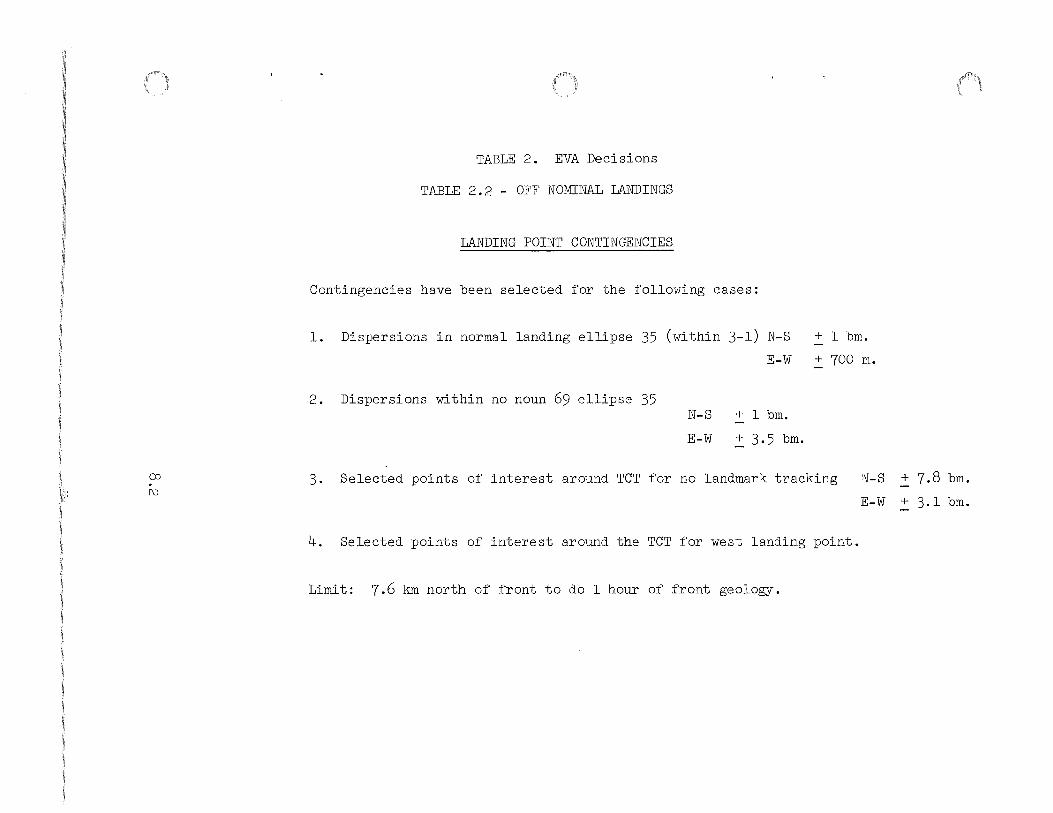
TABLE 2. EVA Decisions
TABLE 2. 2 - OFF NOMINAL LANDINGS
LANDING POINT CONTINGENCIES
Contingencies have been selected for the following cases:
1. Dispersions in normal landing ellipse 35 (within 3-l) N-S + l bm.
E-W + 700 m.
2. Dispersions within no noun 69 ellipse 35 N-S + l bm.
E-W + 3.5 bm.
3. Selected points of interest around TCT for no landmark tracking
4. Selected points of interest around the TCT for west landing point.
Limit: 7.6 km north of front to do l hour of front geology.
N-S .::::_ 7.8 bm.
E-W + 3.1 bm.

CD . w
LANDING POINT (GRID LOCATION)
2 - 0
2 - l
2 - 2
TABLE 2. EVA Decisions
TABLE 2. 2 - OFF NOMINAL LANDINGS
EVA - l
Gain time for front exploration (approx. 10 min.)
Essentially nominal
Same as 3 - 2
EVA IMPACT AND ACTION
EVA- 2
Essentially nominal (move Station 8)
Essentially nominal (move Station 8)
Same as 3 - 2
..
EVA- 3
Addition of l bm Reduce 10 to 15 minutes from North Complex
Same as 2 - 0
Same as 3 - 2

CD . +
LANDING POINT (GRID LOCATION)
3 - 0
3 - l
3 - 2
3 - 3
3 - 4
TABLE 2. EVA Decisions
TABLE 2 . 2 - OFF NOMINAL LANDINGS
EVA IMPACT AND ACTION EVA- l
No significant impact Adjust traverse distances and times
Normal landing point.
Minor adjustment to distances
Do traverse on east side of sec crater cluster Do ALSEP on Refern.
Same as 3 - 3
EVA- 2
No significant impact Station 5 may be beyond distance limit
Normal landing point.
Minor adjustments to distances
a) Approx. l~ hr. at Front (1,2,3) + approx. l hr. 24 min. of Stop 8
b) Approx. l~·hr. at 1, 2, 3 + traverse along Front toward Stop 6. + Stop 8
a) Approx. l~ hr. at Front (1, 2, 3) + Rille tasks 9, 10, ll one bm. south of planned site. + Station 8
b) Approx. 1~ hr. at Front + traverse along Front toward Stop 7 + Stop 8
<!>
EVA - 3
No significant impact
Normal landing point.
Shorten Station 14 to accommodate tasks from EVA l, 2.
a) North Complex - Sta.l2 & 13 + Mare Stops within 3.7 bm.
b) Rille Stops only (9,10,11) +Mare Stops within 3.7 bm.
a) North Complex - Sta. 12 & 13 +Mare Stops within 3.7 bm.
b) Rille Stops only (9, 10, ll) + Mare stops within 3.7 bm.

():) . \Jl
..
LANDING POINT (GRID LOCATION)
4 - 0
4 - l
4 - 2
4 - 3
TABLE 2. EVA Decisions
TABLE 2. 8 - OFF NOMINAL LANDINGS
EVA IMPACT AND ACTION EVA- l
Adds 16 min driving time 16 min. of tasks at end of EVA l. Accomplish later EVA's.
Same as 4 - 0
Adds l km distance to Front (16 min. driving time) Same as 4 - 0
Adds 25 min. driving time. Present ground rules call for deleting 25 min. of post ALSEP.
EVA - 2
Adds 16 min. driving time a) Drive by Stop 4
and return after Front Stops. If it looks important.
b) Do all or part of
EVA - 3
Pursue normal EVA -consider further N. Complex and/or further exploration up the Rille
8 depending importance of 4.
c) May not reach Sta. 5 d) Add in EVA l LM tasks
at LM. Move 8 in close to LM
Same as 4 - 0
Same as 4 - 0
a) Adds 25 min. drive time on normal EVA 2 traverse.
b) Use approach to east of secondary crater cluster means new location for Station 4 (33 min. to front crater.)
Same as 4 - 0
Adds l km to Rille (8 min. NET drive time) May have to pickup up to 30 min. tasks from EVA Sta. 8. Near LM.
Adds 33 min. drive time Delete SSS's Delete 16 min. at 12, 13 Do leftover tasks at 1M with LM tasks to eliminate extra stop and allow completion of Sta 8 tasks at same site.

LANDING POINT ( GRID LOCATION)
4 - 4
4 - 3b
CD . 4 - 4b 0\
6 ~;-----.....__ ~
TABLE 2. EVA Decisions
TABLE 2.2 - OFF NOMINAL LANDINGS
EVA IMPACT AND ACTION EVA- 1
Adds 41 min. driving time Treat as 45 min. late at Stop l.
Traverse to South in vicinity of Front crater -Return to deploy ALSEP ( 50 MN time at Front).
Same as 4 - 3b. (1 hr. at Front)
EVA--~ ·---- .. ··m-~3
Same as 4 - 3.
Traverse to Front in vicinity of Elbow and St.George (Sta. 1,2,3) and traverse to Rille (Sta. 9,10,11).
Same as 4 - 3b. (1 hr. 3 min. at Front) (l hr. at Rille)
Must shorten 9, 10, 11 by 20 minutes. Keep 12, 13 within walk back limit. Stop 14 can be increased by 15 min. because of walk back. Remaining tasks from EVA 1.
Traverse to North Complex and Mare.
Same as 4 - 3b .

CD
--.::)
TABLE 2. EVA Decisions
TABLE 2.2 - OFF NOMINAL LANDINGS
CONTINGENCY LANDING POINT ON WEST SIDE OF RILLE
(Degraded descent propulsion)
Prime Targets:
1. Detailed sampling at Bridge Crater to look for Front throwout -
breccias - radial sampling.
2. Sampling of Mare using craters such as Crook and OS.
3. Sampling of Rays.

"'
12
OFF NOMINAL LNDING SQUARE EVA-II
10
8
.........
:2 ::::.:::: -....;
:2 6 co .-I . :2 -..() 0
0:::
6,7-3-3b 4-4bl3-4b
3-4a 9 10 11 1.1.. 9,10,113-3a f-(/")
Cl 4
4-3b
2
0.4 0.2 LM TASKS
DIST. FRO Ill LRV CKM) 0 1 2 3 4 -j
Tl ME CHOURS)

12
1 I I I I I I I I OFF NOMINAL LNDING
SQUARE EVA-II
101 I I I I I I I I 3-0 No significant change to normal
~ 8 ~ ..._,
~ ...J
~ 0 0:::: L1.. 6
co ........ 1-
0 en 0
4
I I I I
0.4 0.2
DIST. FROM LRV <KM) lo
I
l I
1 2
6,7 4-3a 4-4a
3-1 Normal 3-2 No significant change to normal
3
5,6,7
\ 4-01\ .. 4-1 4-2
ILM TASKSI
4
TIME CHOIIRS 1
1\
ALSEP I
5
4-0 4-1 4-2
LM 4
45~CLOSE OFF
6 7

........
~ ~ ........
~ ...1
~ 0 0:::
co lJ.. . I-' 1-I-' (./) -0
12.r-----t-----r-----r-----r---~r----.----~------
OFF NOMINAL LNDING SQUARE EVA-Ill
10~------~-------r------~--------r-------~-------r-------4------~
8
61 I I
4 I I I I
f 9,10,11 I 4-4
- __ • __ q-_5 / I 12,13
3-0 No significant change 3-1 Normal 4-0 Normal with short dist. 4-1 Normal
2~------4-------~------~------~-------+-+~--~~~--~r-----~
DIST. FROM LRV (KM) 10 1 2 3 5 6 7
TIME <HOURS)

·~
12
OFF NOMINAL LNDING SQUARE EVA-Ill
10 I
8
I 1\ \
....--.
::2 :::.::: ..._,
::2 ....J
::2 6 co 0 . 0:::: I-' LL... N .
12,13 [\...
I ~
I 9,10 11 I \~ I 2-0 \ 2-1 \ I
I-<f)
0 4
2
I I I I I ~ 0.4 0.2 I 1 LM TASKS 1 ALSE p I 45 I I CLOSE
OFF DIST. FROM LRV <KM) 0 1 2 3 4 5 6 7
TIME <HOURS)

12
OFF NOMINAL LNDING SQUARE EVA-Ill
10
2-0
,..... 8
2
3-3a I 12 13 r\. 3-3b
~ J3-4a ~ 3-4a
I ~9,10,11 1;,13\ \ 3-4b
/3-4b '3-3a\ \\
I 3-3b \\ \ \\ BoriD
3-4a 3-3a 3-3b 3-4b\ \ ,
:2: ~ ._..
> co 0::: . ...J 1--' lN :::2: 6
0 0::: LL. . 1-(/) -0
4
l _. I I \ - I I LM TASKS I ALSEP I 45 1/ 1CLOSE
OFF DIST. FROM 0 1 2 3 4 5 6 7
TIME <HOURS)

TABLE 2. EVA DECISIONS
TABLE 2.3 - DELAYED EVA TIMELINES
9
'-0
1-'
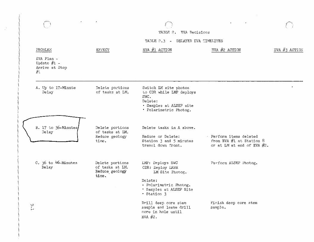
PROBLEM
EVA Plan -Update #l -Arrive at Stop #l
A. Up to 17-Minute Delay
B. 17 to 36-Minutes Delay
C. 36 to 46-Minutes Delay
EFFECT
Delete portions of tasks at LM.
Delete portions of tasks at LM. Reduce geology time.
Delete portions of tasks at LM. Reduce_ geology time.
TABLE 2. EVA Decisions
TABLE 2.3 - DELAYED EVA TIMELINES
EVA #l ACTION
Switch LM site photos to CDR while LMP deploys swc. Delete: • Samples at ALSEP site • Polarimetric Photog.
Delete tasks in A above.
Reduce or Delete: Station 3 and 5 minutes travel down front.
LMP: Deploys SWC CDR: Deploy LRRR
LM Site Photog.
Delete: • Polarimetric Photog. • Samples at ALSEP Site • Station 3
Drill deep core stem sample and leave drill core in hole until EVA#2.
EVA #2 ACTION
Perform items deleted from EVA #l at Station 8 or at LM at end of EVA #2.
Perform ALSEP Photog.
Finish deep core stem sample.
EVA #3 ACTION

PROBLEM
D. 46 to 54-Minutes Delay
E. More than 54-Minutes Delay
'-0
f\)
EFFECT
Must shorten geology time. Delete portions of tasks at LM.
Must shorten time at Front. Delete portions of tasks at LM.
TABLE 2. EVA Decisions
TABLE 2.3 - DELAYED EVA TIMELINES (CON'T)
EVA #1 ACTION
Deploy LRRR
Delete: Polarimetric Photog.
· Samples at ALSEP Site · Station 3
Drill deep core stem sample and leave drill core in hole until EVA #2.
Leave drill at ALSEP site in proper oriented stowed positions.
Deploy LRRR
Shorten time at Front.
Delete: Polarimetric Photog.
• Samples at ALSEP Site Station 3 Delete portions of ALSEP deployment.
EVA #2 ACTION
Perform ALSEP Photog. Do SWC Deployment. Do LM Site Photos.
Finish deep core stem sample. Do Station 8 activities at ALSEP site. Comprehensive Sample (negates need for ALSEP samples)
Rake Sample Double Core Sample Soil Sample
• Rock Sample • Deep Trench Sample • Trench Samples
Special Environmental Sample (SESC)
Do SWC Deployment. Do LM Site Photos. Do ALSEP Photos. Drill deep core stems. Finish ALSEP deployment. Do Station 8 activities at ALSEP site. Comprehensive Sample (negates need for ALSEP samples)
Rake Sample Double Core Sample Soil Sample
• Rock Sample Deep Trench Sample Trench Samples Special(Envitonmental Sample SESCJ
8""?.'
EVA #3 ACTION
Return to Front or North Complex depending on real time evaluation of EVA #1 and EVA #2.

\.0
w
PROBLEM
F. More than 90-Minutes Delay
EFFECT
a) If 1-hour minimwn at Front is possible ---
b) If 1-hour minimwn at Front is not possible.
,0
TABLE 2. EVA Decisions
TABLE 2.3 - DELAYED EVA riMELINES (CON'T)
EVA #l ACTION
Do Front traverse. Delete portions of ALSEP deployment.
Delete Front traverse. Perform ALSEP
· deployment
EVA #2 ACTION
Front traverse -to St. George and traverse to East.
~~
EVA #3 ACTION
Return to Front or North Complex depending on real time evaluation of EVA #l and EVA #2.

'-0
+
PROBLEM
EVA Plan -Update #2 -Arrive at LM Late For ALSEP Deployment
17-Minute Delay
36-Minute Delay
46-Minute Delay
46-91 Minute Delay
90-105 Minute Delay
105-135 Minute Delay
135 + Minute Delay
ff~~ ~ 1
TABLE 2. EVA vecisions
TABLE 2. 3 - DELAYED EVA TIME LINES (CON' T)
EFFECT
Delete tasks at LM
Delete tasks at LM
Delete tasks at LM
Cannot complete all of ALSEP deployment .
Cannot complete ALSEP C/S Deployment
Cannot emplace ALSEP at site.
Cannot offload ALSEP.
EVA #l ACTION
Same as 17-min. late at Stop l.
Same as applicable Stops in 36-min. delay at Stop 1, plus may drill deep core sample and leave drill core in hole until EVA #2.
Same as 46- min. late at Stop l.
Leave ALSEP at completion of last experiment deployment.
Offload, carry ALSEP to site, fuel RTG and connect cable.
Offload ALSEP -do not fuel.
Deploy SWC, flag polarimetric photog, etc.
EVA #2 ACTION
Finish deep core sample.
Finish deep core sample.
Complete ALSEP at beginning EVA #2 (0-40 min. required)
Complete ALSEP at beginning EVA #2 (60-min. required)
Complete ALSEP at beginning EVA #2 (l + 35 required)
Complete ALSEP at beginning EVA #2 (2 + 40 required)
EVA #3 ACTION
Same as EVA #l cant arr Stop l.
II II II II
II II II II
II II II II
II II II II
II II II II
II II II II
\0
Vl
PROBLEM
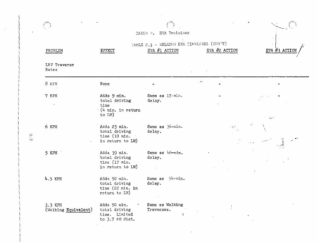
LRV Traverse Rates
8 KPH
7 KPH
6 KPH
5 KPH
4.5 KPH
3.3 KPH (i-lalking Equivalent)
TABLE 2. EVA Decisions
TABLE 2.3 - DELAYED EVA TIMELINES (CON'T) EFFECT EVA #1 ACTION EVA #2 ACTION
None
Adds 9 min. total driving time
· (4 min. in return to LM)
Adds 23 min. total driving time (10 min. in return to LM)
Adds 39 min. 'total driving time (17 min. in return to LM)
Adds 50 min. total driving time (22 min. in return to LM)
Adds 50 min. total driving time. Limited to 3.7 KM dist.
Same as 17-min. delay.
Same as 36-min. delay.
S arne as 46-min. delay.
Same as 54-min. delay.
Same as Walking Traverses.
. ~'
. : .'· \ \
""--' '....._ ---- ··-
EV~ k3 ACTION 1/ I
.--·"· 'j
' .. ':·•·.

. ~ ,<""-, . '~ ""·• A~
trtirf'+t·ctt{""'"""-"\{ ··+t't'f&rtf±'lfitet<1
' , ,t1t..ittr;,,;i.)it»M~'ni>d"tl1;,f'MtfMtJlt~·mh~ ..... H?t"6)'!¥edt (~)\.i·fi&!ft..up.·jj;•f'lf.'". ":ftfs'i•·e:.t';ri'a·r~.c·•'&et(t··i&Nirtt·•l 4 r;s r w··WW {- -~'il.·L~~~~.....:...a.:
\.0
0'\
LRV TRAVERSE
RATE
8 KPH
7 KPH
6 KPH
5 KPH
4 KPH
3.3 KPH
TABLE 2. EVA Decisions
TABLE 2.3 - DELAYED EVA TIMELINES (CON'T)
EFFECT ON EVA- 2
None
Adds 17 min driving time (stop 5 outside LRV/BSLSS limit)
Adds 41 min driving time
Adds 71 .min driving time
Adds 119 mi~ driving time (max distance ~4.1 KM with Zero range from LRV limit.)
Limited to 3.7 KM (BSLSS/OPS limit)
ACTION
Preplanned.
Reduce distance along front to keep science time same. Eliminate stop 5 (can go Z 2.75 KM past turn do stop 6 and 7 select feature to do 5 type activities.
Reduce distance down front between 7 and 6 ~ time on front. Consider deleting
--( stop 4'land reducing stop 8 . ......____/
Reduce distance down front · ~0 time on front. Consider deleting
, stop 4 and reducing stop 8. ·
Consider going to front toward west to ~ance from LRV higher. . ~ ~ reduce stop 8.
Same as walking traverse.
tzj ::s 0 1-' 0 Cll
~ <D
+="

• TABLE 2. EVA DECISIONS
TABLE 2.d - EVA WALKING TRAVERSE
10


TABLE 2 Decisions
TABLE 2.4 - EVA I WALKING TRAVERSE
ELAPSED STATION/ Tif4E AT SEGMENT
· ACTIVITY START TIME GEOLOGICAL FEATURES OBSERVATIONS AND ACTIVITIES ---LM - 1:43 SMOOTH MARE SEE SECTION
TRAVEL 1:43 1:10 ACROSS TYPICAL SMOOTH MARE FILL OBSERVE AND DESCRIBE TRAVERSE OVER TOWARD RH1 OF HADLEY RILLE Sr400TH ~1ARE FILL MATERIAL
DESCRIBE SURFACE FEATURES AND BLOCK DISTRIBUTION
NOTE ANY DIFFERENCES BETWEEN MARE AND RILLE RIM MATERIAL · .
a 2:53 0:15 NEAR SOUTHERN PART OF ELBOW RADIAL SAMPLING OF ELBOW CRATER PAN CRATER EJECTA BLANKET
I-' 1\)
TRAVEL 3:08 0:17 TO APENNINE FRONT SLOPE NORTH LOOK FOR CHANGES IN LITHOLOGY OR OF ST. GEORGE CRATER .. GROUND TEXTURE AS INDICATIONS OF
BASE OF FRONT COf•IPARE r~ARE AND RILLE RIM MATERIAL
TO APENNINE FRONT OBSERVE CHARACTER AND DISTRIBUTION
OF ST. GEORGE EJECTA BLANKET
b 3:25 0:43 NEAR BASE OF APENNINE FRONT· RADIAL SAt,IPLE OF ST. GEORGE CRATER NORTH OF ST. GEORGE CRATER AS SLOPE PERMITS
COHPREHENS IVE SAr1PLE AREA AT APENNINE FRONT
DOUBLE CORE TUBE , STEREO PAN FROM HIGH POINT • lOb m
BASE ALONG FRONT FILL SESC AT APENNINE. FRONT
,,
....
. .

) TABLE 2. EVA Decisions·
• TABLE 2.4 - EVA I WALKING TRAVERSE {CONT)
ELAPSED STATION/ TUitE AT SEG~lENT ACTIVITY START TH1E GEOLOGICAL FEATURES OBSERVATIONS AND ACTIVITIES
TRAVEL 4:08 0:13 ACROSS BASE OF APENNINE FRONT OBSERVE APENNINE f1ATERIAL AND ADJACENT TO POSSIBLE DEBRIS RELATION TO MARE SURFACE FLOW
c 4:21 0:16 AT BASE OF APENNINE FRONT EXA~liNE FLOW AND C0~1PARE TO MARE AND ADJACENT TO POSSIBLE DEBRIS FRONT FLOW DOCUMENTED SAMPLES OF APENNINE FRONT
AND 1 FLOW 1 MATERIAL OBSERVE AND DESCRIBE VERTICAL AND
LATERAL CHANGES IN APENNINE FRONT; t-'
C0~1PARE TO PREVIOUS STOP [\.) PAN . t-' OBSERVE CHARACTERISTICS OF EVA III
ROUTE ..
TRAVEL 4:37 1:23 FROM BASE OF APENNINE FRONT OBSERVE CHARACTERISTICS AND EXTENT ACROSS MARE TO LM OF POSSIBLE DEBRIS FLOW
OBSERVE AREA TO BE TRAVERSED ON EVA II I
COMPARE MARE MATERIAL TO APENNINE ;
FRONT AND RILLE RIM OBSERVE POSSIBlE RAY MATERIAL
: i
LM 6:00 1:00 SMOOTH MARE LM AREA ACTIVITIES EVA CLOSEOUT ;
•

----·----- -·---. ------··--
TABLE 2. EVA Decisions
TABLE 2.4- EVA II WALKING TRAVERSE (CONT)
ELAPSED STATION/ TIME AT SEGMENT ACTIVITY START TI!4E GEOLOGICAL FEAJURES OBSERVATIONS AND ACTIVIT:I£5
LM - 2:48 SMOOTH MARE EGRESS U1 ALSEP DEPLOYMENT
J' PRE~ARE FOR TRAVERSE
TRAVEL 2:48 0:34 ACROSS Sf~OOTH t<'ARE BETWEEN LM C0!1PARE St,lOOTH MARE MATERIAL TO RILLE AND RIM OF HADLEY RILLE RH1 I~ATERIAL
d 3:22 0:31 AT RIM OF HADLEY RILLE OBSERVE AND DESCRIBE RILLE AND FAR HALL
500-mm LENS CAMERA PHOTOGRAPHY 1-' COiWREHENSIVE SAMPLE AREA [\)
SINGLE (DOUBLE) CORE TUBE . [\)
PAN DOCUMENTED SAt~PLING OF CRATER AT
EDGE OF RILLE
TRAVEL 3:53 0:29 ALONG RILLE RIM TO TERRACE DESCRIPTION OF RILLE AND RIN MATERIAL PHOTOGRAPHY AS APPROPRIATE
e 4:22 0:28 RILLE RIM AT TERRACE OBSERVE AND DESCRIBE RILLE AND FAR RILLE WALL; CONPARE TO PREVIOUS _ OBSERVATIONS
500-mm LENS CAMERA PHOTOGRAPHY DOCUMENTED SAMPLES OF RILLE RI~1 AND
CRATER AT EDGE OF RILLE· PAN COMPARE RILLE RIM MATERIAL·TO OTHER
TERRAIN

TABLE 2. EVA Decisions
TABLE 2.4- EVA II WALKING TRAVERSE {CONT)
ELAPSED STATION/ TI~iE AT SEG~1ENT ACTIVITY START TIME . GEOLOGICAL·FEATURES OBSERVATIONS AND ACTIVITIES
TRAVEL 4:50 0:48 FROM RILLE RIM EAST ACROSS MARE OBSERVE CHANGES IN MATERIAL BETWEEN RILLE RIM AND MARE
f 5:38 0:37 160 m CRATER IN MARE CDr4PREHENSIVE SAt4PLE AREA DOUBLE CORE TUBE DOCUMENTED SAMPLING OF LARGE 14ARE
CRATER POSSIBLE FILLET/ROCK S~~PLE POSSIBLE LARGE AND SMALL
t-' EQUIDIMENSIONAL ROCK SAMPLES 1\) . w PAN
TRENCH POSSIBLE BURIED ROCK SA~iPLE
_, .. FILL SESC ,., ... - .,
TRAVEL. 6:15 0:10 ·· .. ·. ACROSS SMOOTH MARE. CONPf id: MARE MATERIAL WlT;1 c,·, { '::R TERRAIN { .~ ;
OBSERVE POSSIBLE RAY MAHi'.L ... . ~ · .. , '. '. ~.
LM 6:25 0:35 SMOOTH MARE EVA CLOSEOUT ' ..

TABLE 2. EVA Decisions
TABLE 2.4 - EVA III WALKING TRAVERSE (CONT)
ELAPSED STATION/ TI~1E AT SEGMENT ACTIVITY START TIME GEOLOGICAL FEATURES OBSERVATIONS AND ACTIVITIES
• LM - 0;22' SMOOTH MARE EGRESS LM, PREPARE FOR TRAVERSE
TRAVEL 0:22 1:19 SOUTH ALONG S~100TH MARE ON WEST OBSERVE SMOOTH MARE CHARACTERISTICS SIDE OF SECONDARY CRATER CLUSTER OBSERVE SECONDARY CRATER CLUSTER TO BASE Qf APENNINE FRONT CHARACTERISTICS
PHOTOGRAPHY AS APPROPRIATE • .
9 1:41 0:48 SLl~~N~~~E~R~~~R BAS~ OF'. DOCUMENTED SAMPLES: SLIDE CRATER IN APENNINE FRONT OTHER AREAS
STEREO PAN; 100-m SEPARATION ALONG f-'
APENNINE FRONT 1\) EXPLORATORY TRENCH UPSLOPE OF SLIDE 0 . ... -!="" r CRATER Iii-.,..,,..... -· 70-mm CA~IERA STEREO PAIRS UPSLOPE
AT TARGETS OF OPPORTUNITY
TRAVEL 2:29 0:12 EAST ALONG APENNINE FRONT TRAVERSE ALONG APENNINE FRONT OBSERVE POSSIBLE DEBRIS FLOWS, SOURCE
AND DOWNSLOPE MOVEMENT PHOTOGRAPHY AS APPROPRIATE
h 2:41 0:34 AT BASE OF APENNINE FRONT DESCRIPTION OF APENNINE FRONT IN NEAR SMALL CRATER SJ',MPL I NG AREA
COMPARISON OF APENNINE FRONT AND MATERIAL TO OTHER SURFACE UNITS
DOCUMENTED SAMPLES OF APENNINE FRONT 11ATERIAL
PAN EXPLORATORY TRENCH POSSIBLE CORE TUBE 70-mm CAMERA STEREO PAIRS OF TARGETS
OF OPPORTUNITY UPSLOPE

•
t-' 1\) . \.Jl.
STATION/ ACTIVITY
TRAVEL
i
TRAVEL
U1
··.· . . ·, . ...
ELAPSED TI~tE AT
START
3:15
3:39
~
4:00 .. i
5:15
TABLE 2. EVA Decisions
TABLE 2.4 - EVA III WALKING TRAVERSE (CONT)
TIME GEOLOGICAL FEATURES OBSERVATIONS AND ACTIVITIES
0:24 FROM BASE OF APENNINE FRONT TO OBSE.RVE SECONDARY CRATER DEPOSITS SOUTH OF DUNE CRATER IN AND RELATION TO OTHER TERRAIN SECONDARY CLUSTER OBSERVE EASTERN EDGE OF POSSIBLE
DEBRIS FLOW FROM APENNINE FRONT · PHOTOGRAPHY AS APPROPRIATE
0:21 SECONDARY CRATER CLUSTER: SOUTH SOIL SANPLE OF D~NE CRATER DOCUMENTED SAMPLING
PAN EXPLORATORY TRENCH POSSIBLE CORE TUBE THROUGH SECONDARY
EJECTA OBSERVE CRATER INTERIOR AND EJECTA SM~PLE TYPICAL AND EXOTIC ROCK TYPES COMPARE SECONDARY CRATER t~Jl.TfiR~.~L
TO OTHER TERRAIN UNITS :;;.: · ~:\c ~ . ;. :··~.
1:15 ALONG WEST SIDE OF SECONDARY OBSERVE SECONDARY CRATER DEPQS~;S CRATER CLUSTER, AND ACROSS COMPARE MARE MATERIAL WITH c·rrh::r, S~lOOTH ~1ARE TERRAIN
OBSERVE POSSIBLE RAY MATERIAL
0:45 St·100TH MARE EVA CLOSEOUT
•'.:'
'····· '•

t-' w
EVENT NO.
l.
2.
3.
TABLE 3. MESA Deployment
CONTINGENCY AGENT ACTION
MESA release handle will not I Crewl 1. Attempt to free release release. handle by exerting side loads
on pip pin.
Crew I 2. Attempt to reach cable from release handle to MESA. Pull on this cable or cable bell crank mechanism with hand to deploy MESA.
Crew 3. Attempt to reach cable beyond bell crank and pull to deploy MESA.
Release handle releases, MESAl Crew does not deploy.
1. Try repeated pulls on release handle.
MESA fails to stop and hits lunar surface (lanyard breaks).
Crew I 2. Manually deploy MESA from surface with lanyard.
Crew I 3. One crewman pull on MESA lanyard while other crewman pulls release handle.
Crew I l. Attempt to block up MESA with LRRR pallet.
Crew I 2. Attempt to tie up MESA if lanyard available.
REMARKS

I-' .;:::-
EVENT NO.
4.
5.
~
CONTINGENCY
Unable to open SRC
SRC Seal Area Dirty.
TABLE 3. MESA Deployment (Cant' d)
AGENT ACTION
Crew 1. Hit corners o~ SRC lid with available tools and attempt to pull lid ~ree.
Crew 2. I~ ~arced to abandon SRC #1, use MESA sample collec-tion bag ~or Selected Samples and trans~er the bag to LM ascent stage in ETB and stow in the ISA.
Crew 3. I~ ~arced to abandon SRC #2, use MESA sample collec-tion bags ~or documented samples and trans~er the bags to LM ascent stage in the ETB and stow in the ISA.
Crew Use hand brush to clean seal.
REMARKS
Loss o~ SRC #1 will result in the loss o~ 40 documented sample bags, 6 drill stems and 1 environmental soil sample container (SESC) •
Loss o~ SRC #2 will result in the loss o~ 6 core tubes, 2 SESC, and 80 documented sample bags.

I-' \.n
EVENT NO.
6.
J
CONTINGENCY
Unable to latch SRC.
TABLE 3. MESA Deployment (Cont 'd)
AGENT ACTION
Crew I 1. Check that spacer has been removed. I~ not, remove
Crew I 2. Open and look ~or inter~erence.
Crew
a. Relocate item, shake or pat to settle loaded collection bag. I~ "O" ring is out o~ groove, pull out and discard.
b. Remove excess packing material or sample and repac&
3. I~ no apparent inter~erence close and engage other strap latch. If this latch will rotate to within 30° o~ being closed, place other hand on back o~ box to permit application o~ maximum closing pressure by a muscular squeezing action.
a. If this strap latches try ~irst latch again in the same manner.
REMARKS

I-' (}\
EVENT NO.
6. (Cont'd)
7.
TABLE 3.
CONTINGENCY
Unable to trans~er items via LEC.
~-----~~--
MESA Deployment (Cont'd)
AGENT ACTION REMARKS
b. I~ the second latch will not latch, return to earth with the ~irst latch closed.
c. I~ still cannot latch at least one side, abandon SRC.
i
Crew 4. Trans~er samples in Sample Containers.
Crew l. Use LEC as a tether, attach and pull it up to hatch.
Crew 2. I~ possible climb ladder while holding SRC.
-~----- L____ -- •- -----------

J-' ---.:]
EVENT NO.
l.
2.
TABLE 4. Apollo Lunar Hand Tools
CONTINGENCY
Hand tool carrier (HTC) damaged or unuseable.
AGENTI ACTION
Crew I Stow hand tools in bag under seat of' LRV.
ALSEP tool subpallet pull pin I Crew I l. Apply additional f'orce jams. while rotating pin with the
aid of' the second crewman.
Crew I 2. Use hammer to pry pin :free or break pin.
Crew 3. Remove all accessible tools, stow on MESA and deploy subpackage #2 with HTC attached.
REMARKS
There may be a reduced geology capability if' the HTC is not available.
If' subpallet cannot be removed, RTG will not radiate heat evenly, causing excessive heat buildup.

t--' co
EVENT NO.
3.
TABLE 4. Apollo Lunar Hand Tools (Cont'd)
CONTINGENCY AGENT ACTION
ALSEP ~orward tool support Crew l. Apply additional ~orce pull pin jams. on pin with hammer.
Crew 2. Remove UHT and DRT pins, remove UHT's, and attempt to pry open the outer hal~ to break the bracket o~~ at the point where the pin is jammed
Crew 3. Use hammer to break bracket.
Crew 4. The tools can be removed by prying the bracket away ~ar enough to gain access to the tools.
REMARKS
ALSEP cannot be deployed without DRT, FTT and one UHT.
i
1-' \0
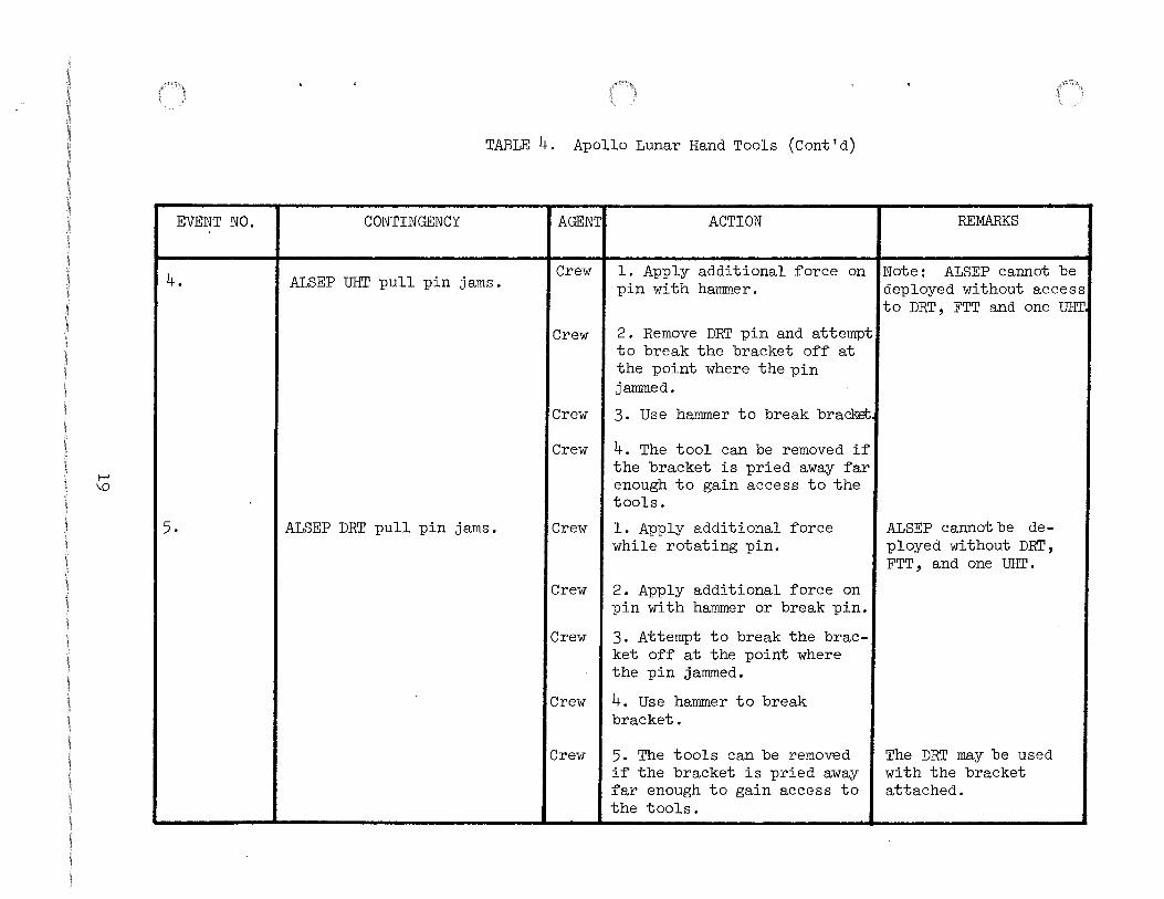
EVENT NO.
4.
5.
TABLE 4. Apollo Lunar Hand Tools (Cont'd)
CONTINGENCY
ALSEP illi.T pull pin jams •
ALSEP DRT pull pin jams .
AGENT. ACTION REMARKS
Crew I 1. Apply additional ~orce on 'Note: ALSEP cannot be pin with hammer. deployed without access
to DRT, FTT and one illi.T.
Crew
Crew
2. Remove DRT pin and attempt to break the bracket o~~ at the point where the pin jammed.
3. Use hammer to break bra~
Crew I 4. The tool can be removed i~ the bracket is pried away ~ar enough to gain access to the tools.
Crew I 1. Apply additional ~orce while rotating pin.
Crew I 2. Apply additional ~orce on pin with hammer or break pin.
Crew I 3. Attempt to break the bracket o~~ at the point where the pin jammed.
Crew I 4. Use hammer to break bracket.
Crew I 5. The tools can be removed i~ the bracket is pried away ~ar enough to gain access to the tools.
ALSEP cannot be deployed without DRT, FTT, and one UHT.
The DRT may be used with the bracket attached.

(\) 0
EVENT NO.
6.
7.
8.
TABLE 4. Apollo Lunar Hand Tools(Cont'd)
CONTINGENCY AGENT:
Handle comes off Contingency I Crew Lunar Sample Return Container before sampling, container falls on lunar surface. ICrew
Handle will not come off Contingency Lunar Sample Return Container after sampling.
Crew
Unable to open special envir-ICrew onmental sample containers (SESC).
ACTION
l. Attempt to retrieve with handle.
2. Get tongs and retrieve bag from surface, then reinstall bag ring on handle.
l. Remove clip.
2. If handle is stuck, bend sampler toward cup ring until bag retaining pin is free of cup ring (approximately 90°) and remove bag.
l. Unable to open - hit rotation handle with hammer.
Crew I 2. Unable to seal - check/ remove both seal protectors. Check/free lanyard if impeding proper lid manipulation.
REMARKS
If it is not possible to open and close container, abandon sample task.
[\) 1-'
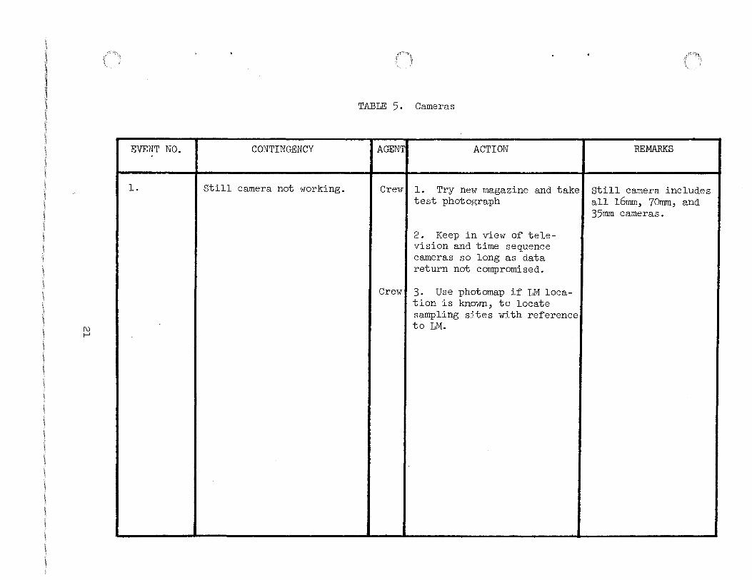
EVENT NO.
l.
CONTINGENCY
Still camera not working.
TABLE 5. Cameras
AGENT ACTION REMARKS
Crew l. Try new magazine and take Still camera includes test photograph all l6mm, 70mm, and
35mm cameras.
2. Keep in view of tele-vision and time sequence cameras so long as data return not compromised.
Crew 3. Use photomap if LM loca-tion is known, to locate sampling sites with reference to LM.

1\) 1\)
EVENT NO.
l.
2.
3.
4.
5.
6.
7.
8.
TABLE 6.
CONTINGENCY
Pole will not go into surface.
Pole partially extended.
Solar Wind Composition Experiment
AGENT
Crew
Crew
ACTION
Lean against LM, facing sun.
l. If' pole is half' or more of' normal length, continue experiment.
Crew I 2. Remove f'oil and proceed to event 6.2.
Reel not removable. No f'oil ICrew exposed to solar radiation.
Discard experiment.
Foil torn during extension.
Foil comes of'f' reel.
Foil reel comes of'f' poles.
Unable to reroll f'oil by spring.
No SWC bag available.
Crew Continue experiment.
Crew Hang f'oil on pole by lanyard.
Crew l. Reconnect to pole.
Crew I 2. Hang f'oil on LM structure facing most available solar radiation.
Crew I Roll by hand or f'old as conveniently as possible.
Crew I Continue experiment. Bag not mandatory. Attempt to put a bag over each end.
REMARKS
1\)
w
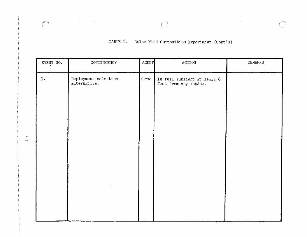
EVENT NO.
9.
TABLE 6.
CONTINGENCY
Deployment selection alternative.
Solar Wind Composition Experiment (Cont'd)
AGENT ACTION REMARKS
Crew In full sunlight at least 6 feet from any shadow.
--~ ---------
[\)
+
EVENT NO.
1.
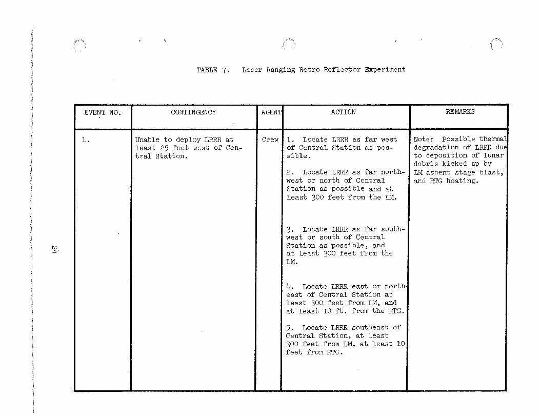
TABLE 7. Laser Ranging Retro-Re~lector Experiment
CONTINGENCY
Unable to deploy LRRR at least 25 ~eet wBst o~ Central Station.
AGENTI ACTION
Crew I 1. Locate LRRR as ~ar west o~ Central Station as possible.
2. Locate LRRR as ~ar northwest or north o~ Central Station as possible and at least 300 ~eet ~rom the LM.
3. Locate LRRR as ~ar southwest or south o~ Central Station as possible, and at least 300 ~eet ~rom the LM.
4. Locate LRRR east or north east o~ Central Station at least 300 ~eet ~rom LM, and at least 10 ~t. ~rom the RTG.
5. Locate LRRR southeast o~ Central Station, at least 300 ~eet ~rom LM, at least 10 ~eet ~rom RTG.
REMARKS
Note: Possible therma degradation o~ LRRR due to deposition o~ lunar debris kicked up by LM ascent stage blast, and RTG heating.
[\) \Jl
EVENT NO.
2.
3.
4.
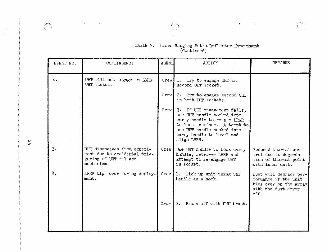
TABLE 7. Laser Ranging Retro-Re~lector Experiment (Continued)
CONTINGENCY
UHT will not engage in LRRR UHT socket.
UHT disengages from experiment due to accidental triggering o~ UHT release mechanism.
LRRR tips over during deployment.
AGENT. ACTION
Crew I 1. Try to engage UHT in second UHT socket.
Crewl 2. Try to engage second UHT in both UHT sockets.
Crewl 3. I~ UHT engagement ~ails, use UHT handle hooked into carry handle to rotate LRRR to lunar sur~ace. Attempt to use UHT handle hooked into carry handle to level and align LRRR.
Crew I Use UHT handle to hook carry handle, retrieve LRRR and attempt to re-engage UHT in socket.
Crew I 1. Pick up unit using UHT handle as a hook.
Crew I 2 . Brush of~ with EMU brush.
REMARKS
Reduced thermal control due to degradation o~ thermal point with lunar dust.
Dust will degrade performance i~ the unit tips over on the array with the dust cover 0~~.

1\)
0\
EVENT NO.
5.
6.
TABLE 7. Laser Ranging Retro-Reflector Experiment (Continued)
CONTINGENCY
Leveling leg pull pin jams or unable to deploy.
Reflector array pull pin jams or lanyard breaks.
AGENTI ACTION
Crewl l. Attempt to pry pin out or jar leg free.
Crewl 2. Attempt to level using core tube or penetrometer for props.
Crewl l. If lanyard breaks, attempt to remove pin manually.
Crewl 2. If pin jams, apply additional force while rotating pin.
Crewl 3. Apply additional force with hammer or break pin.
Crewl 4. Use hammer to break bracket.
Crewl 5. Leave reflector array in stowed position, but continue with LRRR deployment.
REMARKS
Leveling may be out of limits.
Experiment a1m1ng accuracy stability on the thermal control may be degraded.
Experiment science data may be degraded.

EVENT NO.
7.
TABLE 7. Laser Ranging Retro-Reflector Experiment (Continued)
CONTINGENCY
Small array will not fully rotate or lock in position.
AGENTI ACTION
Crewl l. Examine for obstructions, dislodge obstructions with UHT or MESA tools and rerotate small array into deployed position.
Crewl 2. Leave small array in partially deployed position. Continue with LRR deployment.
REMARKS
Force small array into deployed position if necessary.
Experiment science data may be degraded.
Experiment aiming accuracy may be degraded.
Without accurate leveling and alignment science data and thermal control will be degraded.

1\) ())
EVENT NO.
10.
11.
l
TABLE 7. Laser Ranging Retro-Reflector Experiment (Continued)
CONTINGENCY I AGENT.
Lunar dust degrades reada- I Crew bility of bubble level or compass rose, or bubble level: or sun compass is damaged.
ACTION
1. Level by using estimation of true vertical and other equipment as a reference, align by using shadows and other equipment as references. Ensure ample photo is obtained to verify experiment orientation.
UHT will not disengage from I Crewll. Apply additional force: LRRR UHT socket.
Crew 2. Obtain assistance from second crewman.
Crewl 3. Leave UHT in socket.
REMARKS
Without accurate leveling and alignment, science data and thermal control may be degraded.
Experiment aiming accuracy, stability or thermal control may be degraded.

1\)
\0
EVENT NO.
l.
2.
3.
CONTINGENCY
SEQ Bay door lanyards unusable (f'or opening)
TABLE 8. ALSEP Of'f'load
8.1 SEQ Bay Door
AGENT ACTION
Crew I l. Lanyard f'ree f'rom cable, pull cable.
Crew 2. Lanyard melted and f'used to Inconel--if' unable to break f'ree with hand pull, use hammer to f'ree and pull cable.
SEQ Bay doors will not open. ICrew I l. No cable movement (worse case) pry open astronaut protection door and f'ail mechanism. Pull on lanyard again.
Crew I 2. Use ha~mer to chop hole in main door Inconel shield at center patch. Hook hammer behind cable and pull to release latch and open door while latch is pulled. Continue to open door upward.
Crew I 3. With small cable movement doors are unlatched and can be opened manually.
SEQ Bay door partially open I Crew and jammed.
l. Continue pulling on lanyard. Get assistance to aid in manually raising door.
Crew I 2. Discontinue use of' lan-yard and manually raise door.
REMARKS

w 0
EVENT NO.
4,
5.
CONTINGENCY
SEQ Bay Door will not lower (~or closing)
SEQ Bay door partially closed
TABLE 8. ALSEP O~~load (Cont'd)
8.1 SEQ Bay Door
AGENT ACTION REMARKS
Crew Attempt to close manually. Note: SEQ Bay door should be closed to thermally insulate the LM.
Crew l. Continue pulling on lan-yard while second crewman manually assists in closing door.
Crew 2. Discontinue use o~ lan-yard and manually close door or use hammer to ~ail mech-anism in order to close door. i
I

w 1-'
EVENT NO.
l.
2.
3.
4.
5.
TABLE 8. ALSEP O~~load (Cont'd)
8.2 Subpackage Removal by Boom
CONTINGENCY
Subpackage latching mechanism will not release.
Subpackage will not slide on rails.
Boom will not deploy.
Boom partially deployed.
Ratchet ~ails.
AGENT ACTION
Crewl 1. I~ lanyard pulls loose or mechanism jams, remove thermal covering ~rom bottom o~ SEQ Bay and attempt to move release mechanism lever ~orward.
Crewl 2. Use hammer to pry outward ~rom structure on right-hand link o~ latching mechanism ~arcing latch over center and releasing packages.
Crewl Get assistance ~rom second crewman.
Crewl Release hockey stick at boom inter~ace and manually deploy subpackage.
Crewl Use two-man deployment: one supports, other man releases hockey stick at boom inter~ace and manually deploys subpackage.
Crew I Use two-man deployment: One supports, other pulls small lanyard to release hockey stick ~rom boom inter~ace and manually deploy subpackage.
REMARKS

w N
EVENT NO.
6.
7.
8.
TABLE 8. ALSEP Of'f'load (Cont 'd)
8.2 Subpackage Removal by Boom
CONTINGENCY AGENT ACTION
White portion of' deployment ICrew lanyard will not release f'rorr.
1. Grasp release latch at base of' subpackage and twist with an upward motion in an ef'f'ort to break the latch or the slot.
base of' subpackage.
Crew I 2. Attempt to cut lanyard witfi hammer against LM or rock to break or tear lanyard (webbing) loose.
Unable to release hockey I Crew 1. Attempt to pull pin manually. stick at boom interf'ace (pin
jams or lanyard breaks) Crew 2. Release hockey stick at
handle interf'ace.
Unable to release hockey I Crew 1. Apply additional f'orce on pin with hammer or break pin.
stick at subpackage interf'ace (pin jams).
Crew I 2. Attempt to break the hockey stick of'f' at the point where the pin jammed either manually or with hammer.
Crew I 3. Attempt to pry hockey stick away f'rom package.
Crew 4. Leave hockey stick on subpackage.
REMARKS
Central Station thermal control may be degraded

w w
EVENT NO.
9.
CONTINGENCY
Boom does not retract.
TABLE 8. ALSEP Offload (Cont'd)
3.2 Subpackage Removal by Boom
AGENT ACTION
Crew l. Attempt retraction by both crewmen working simul-taneously, one pulling the lanyard and the second push-ing on boom (if within reach)
Crew 2. Apply loads on end of the boom with the hammer while second crewman pulls lanyard.
REMARKS
Crewmen should spend a minimum amount of time on task before abandoning.
i
I

l..U -f:"""
EVENT NO.
l.
2.
3.
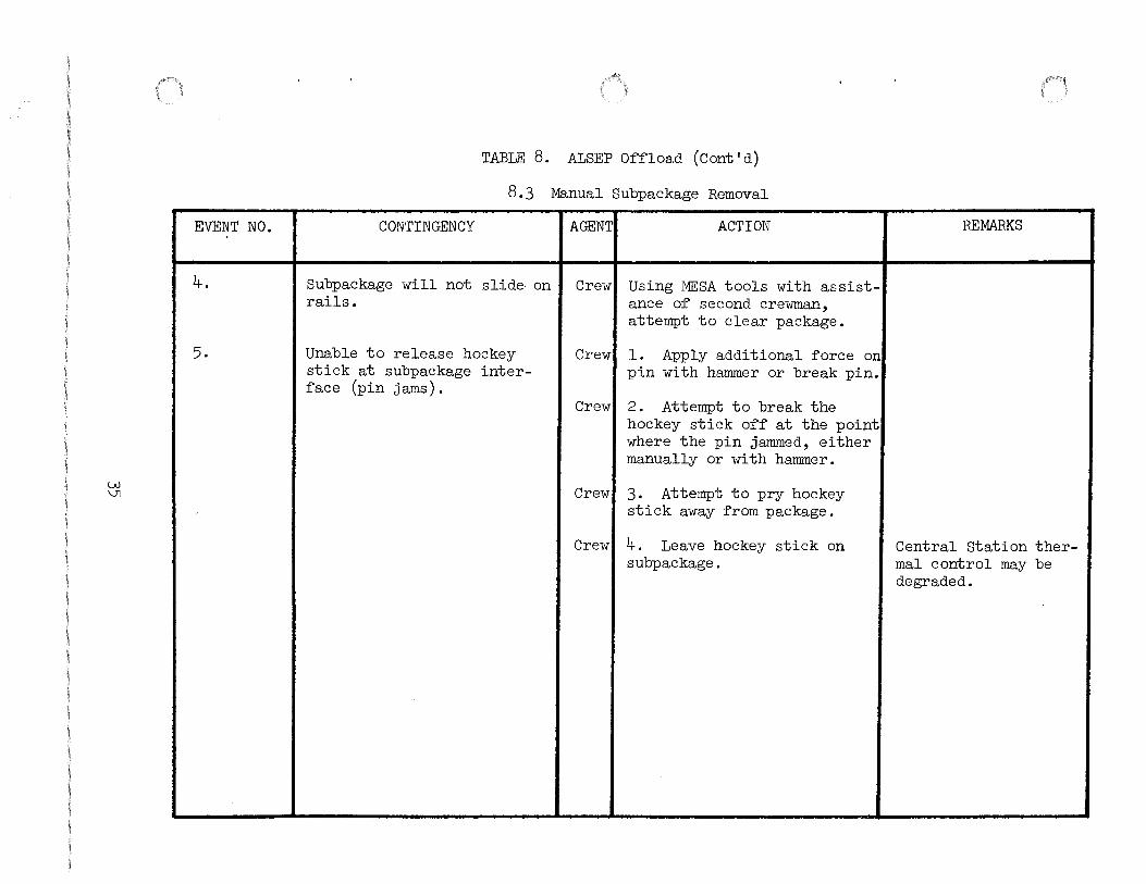
TABLE 8. ALSEP Offload
8.3 Manual Subpackage Removal
CONTINGENCY AGENT ACTION
Unable to release hockey ICrew l. Attempt to pull pin at pin interface. stick at boom interface (Pin
jammed or lanyard breaks)
Subpackage latching mechanism will not release.
White portion of deployment lanyard will not release from base of subpackage.
Crew
Crew
2. Remove package on boom.
3. Remove entire hockey stick by removing pull pin at carry handle interface af'ter boom removal.
Crew I l. If lanyard pulls loose or mechanism jams, remove thermal covering from bottom of SEQ bay and attempt to move release mechanism lever forward.
Crew I 2. Use hammer claw to pry outward from structure on right-hand link of latching mechanism forcing latch over center and releasing subpackages.
1. Grasp release latch at base of subpackage and twist with an upward motion in an effort to break the latch or the slot.
Crew I 2. Attempt to cut lanyard with hammer against LM or rock to break or tear (webbing) loose.
REMARKS
w \Jl
EVENT NO.
4.
5.
TABLE 8. ALSEP Of'f'load (Cant' d)
8.3 Manual Subpackage Removal
CONTINGENCY AGENT ACTION
Subpackage will not slide on Crew Using MESA tools with assist-rails. ance of' second crewman,
attempt to clear package.
Unable to release hockey Crew 1. Apply additional f'orce on stick at subpackage inter- pin with hammer or break pin. f'ace (pin jams).
Crew 2. Attempt to break the hockey stick of'f' at the point where the pin jammed, either manually or with hammer.
Crew 3. Attempt to pry hockey stick away f'rom package.
Crew 4. Leave hockey stick on subpackage.
REMARKS
J ' I
Central Station ther-mal control may be degraded.

w 0\
EVENT NO.
l.
2.
TABLE 9. RTG Fueling
CONTINGENCY
Lanyard breaks or pulls away from cam lever.
Cam lever fails to release the upper trunnion after lever is fully deployed.
AGENTI ACTION
Crew I l. Use hammer/extension as hook and pull forward on cam lever to release
Crew
Crew
Crew
2. If cam lever cannot be released, abandon ALSEP.
l. Use hammer/extension as hook on astronaut guard to break cask free at trunnions while second crewman pulls lanyard to tilt.
2. If upper trunnion cannot be released, abandon ALSEP.
REMARKS
Caution: Direct exposure to hot fuel cask could damage or fail the space suit.

w -'I
EVENT NO.
3.
TABLE 9. RTG Fueling (Cont'd)
CONTINGENCY AGENT ACTION REMARKS
Lanyard fails to remove Crew l. Use hammer/extension to spline lock from cask/dome or release second trunnion lock, breaks. rotate cask if required, and
use hammer/extension as hook to remove spline.
i
'
Crew 2. Rotate cask, attempt to I
gain access to fuel capsule by using hammer/extension to destroy cask dome and pry away bands.
Crew 3. If spline lock cannot be removed from dome, or dome cannot be removed by impact-ing with hammer/extension, abandon ALSEP.
w OJ
EVENT NO.
4.
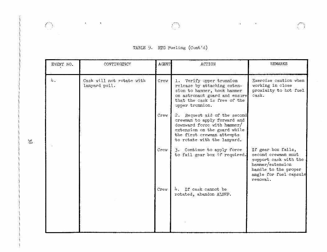
TABLE 9. RTG Fueling (Cont'd)
CONTINGENCY AGENT ACTION
Cask will not rotate with Crew l. Veri~y upper trunnion lanyard pull. release by attaching exten-
sion to hammer, hook hammer on astronaut guard and ensure that the cask is ~ree o~ the upper trunnion.
Crew 2. Request aid o~ the second crewman to apply ~orward and downward ~orce with hammer/ extension on the guard while the ~irst crewman attempts to rotate with the lanyard.
Crew 3. Continue to apply ~orce to ~ail gear box i~ required.
Crew 4. I~ cask cannot be rotated, abandon ALSEP.
REMARKS
Exercise caution when working in close proximity to hot ~uel cask.
I
I
I~ gear box ~ails, second crewman must support cask with the hammer/extension handle to the proper angle ~or ~uel capsule removal.

w \.0
EVENT NO.
5.
TABLE 9. RTG Fueling (Cont'd)
CONTINGENCY
Engaging mechanism on DRT does not lock on cask dome due to mechanical failure.
AGENT ACTION
Crew I l. Apply forward pressure and rotate. Attempt to remove dome with side loading on the DRT so it will be removed with some assistance from the tool. (Caution: Stand clear of dome when finally released and removed.
Crew I 2. After dome is rotated (without locking pin engagement) use hammer/extension to remove dome.
Crew I 3. Attempt to gain access to fuel capsule by using hammer to destroy cask dome and pry away bands.
Crew I 4. If dome cannot be removed, abandon ALSEP.
REMARKS

.(::-" 0
EVENT NO.
6.
7.
TABLE 9. RTG Fueling (Cont'd)
CONTINGENCY
Lock nut assembly will not rotate.
AGENT ACTION
Crew I 1. Apply additional force with hammer on end of the DRT to jar loose the binding while continuing to rotate DRT.
Crew I 2. Attempt to gain access to fuel capsule by using hammer to destroy cask dome and pry away bands.
Crew I 3. If assembly cannot be removed,abandon ALSEP.
Pretension bands do not ICrew l. Use hammer/extension to free lugs at the lock nut assembly on the dome.
release causing excessive loading on dome locking legs.
Crew I 2. Attempt to gain access to fuel capsule by using hammer to destroy cask dome and pry away bands.
Crew 3. If dome cannot be removed,-abandon ALSEP.
REMARKS

+ 1-'
EVENT NO.
8.
TABLE 9. RTG Fueling (Cont'd)
CONTINGENCY AGENT ACTION REMARKS
FTT engagement fingers do not Crew l. Visually inspect fingers expand (inoperative). for debris and re-engage
FTT in fuel cask.
Crew 2. Request aid of second crewman to apply additional force to FTT knob.
Crew 3. Apply impact pressure on knob by knocking on the LM landing gear.
Crew 4. If FTT will not function, the RTG cannot be fueled and ALSEP will be abandoned.

+:-1\)
EVENT NO.
9.
TABLE 9. RTG Fueling (Cont'd)
CONTINGENCY AGENT ACTION REMARKS
Capsule will not release ~rorr Crew 1. Apply additional side cask body a~er FTT is loads by wiggling on FTT attached and locked, while pulling capsule out.
Crew 2. Retract FTT, rotate 120° and repeat task in all three positions.
Crew 3. Using hammer/extension apply impact ~orce on side of cask body to free the caps~.
Crew 4. Using hammer, apply im-pact ~orce on the end o~ the FTT to ~ree the capsule.
Crew 5. Allow ~or back plate cool down (5-10 min.) and repeat task.
Crew 6. I~ capsule cannot be released, abandon ALSEP.

.j::"" w
EVENT NO.
10.
TABLE 9. RTG Fueling (Cont'd)
CONTINGENCY
FTT will not release from capsule while in RTG body.
AGENTI ACTION
Crew I 1. Visually check engagement alignment.
Crew
Crew
2. Check ~or ~ull outward travel o~ FTT ~ingers.
3. Apply additional force to release knob.
Crew I 4. Leave FTT in place on the ~ueled RTG. Manually carry subpackage #2 in the barbell mode, or on the LRV. Monitor the RTG/Capsule during preparation ~or the traverse to the site.
Crew I 5. I~ ~uel capsule is not locked in RTG, carry subpackage #1 in suitcase mode and transport carry bar on LRV.
REMARKS
There will be no problem of excessive heat buildup i~ the FTT cannot be disengaged ~rom the fueled RTG.

+ +
EVENT NO.
11.
y
TABLE 9. RTG Fueling (Cont'd)
CONTINGENCY
Tempilabel indicates temperature of component is in excess of 250~.
AGENTI ACTION
Crew I 1. Do not handle component manually. Use UHT or MESA tool to avoid direct contact with hot component and continue deployment, if possib~;
Crew 2. Unable to continue deployment without coming into direct contact with component, place component in shade and work around hot component until MCC notifies that component should have cooled off enough to permit manual handling.
REMARKS
Caution: Direct exposure to temperatures in excess of 250~ could damage or fail the spacesuit.
Crew should verify that temperature is less than 250°F before handling.

+ \J1
EVENT NO.
l.
CONTINGENCY
Carry bar will not engage in subpackage keyhole socket.
TABLE 10. · ALSEP Traverse
AGENT ACTION
Crew l. Check mating bar to see i~ properly mated. Mating bar could be mated 180° out o~ phase.
Crew 2. Ensure ~lange on carry bar is ~ree o~ debris; i~ not, clean by impact or with gloved hand.
Crew 3. Ensure keyhole socket is clean; i~ not, clean with available MESA tools.
Crew 4. I~ one or both sockets are unuseable, the LMP must carry subpackage #l and sub-package #2 in suitcase mode.
~
REMARKS
The carry bar is required ~or use as an antenna mast and must be transported to the ALSEP deployment site.
I
Transport carry bar on LRV.

+ 0\
EVENT NO.
2.
3.
TABLE 10. ALSEP Traverse (Cont'd)
CONTINGENCY
Carry bar sections become dis engaged and rotate.
Carry bar becomes disengaged from sub package.
AGENTI ACTION
Crewl l. Attempt to relock carry bar sections.
Crewl 2. If carry bar sections do not lock, disengage carry bar from sub packages. Use suitease carry mode and transport carry bar on LRV.
Crewl 1. Attempt to re-engage carry bar in subpackage keyhole socket.
Crewl 2. If carry bar will not remain in keyhole socket, use suitcase carry mode and transport carry bar onLRV.
REMARKS
If carry bar sections do not lock, ensure that sections are properly aligned when they are used as an antenna mast in order to permit proper alignment of ALSEP antenna.
The carry bar is required for use as an antenna mast and must be transported to the ALSEP deployment site.

_J:::--.J
EVENT NO.
4.
CONTINGENCY
Carry bar binds in keyhole socket on subpackage.
TABLE 10. ALSEP Traverse (Cont'd)
AGENT ACTION
Crewl 1. Ensure trigger release is operable.
Crewl 2. If trigger is released, apply additional downward pressure while applying side loads to sub package #2.
Crewl 3. Request aid of CDR to lift subpackage #1.
Crewf 4. ·With second crewman's UHT, depress antenna lock and rotate subpackage #1 to separate masts. With single section attached to subpackage #2, continue as in step #2 above.
Crewl 5. Attempt to break carry bar off at keyhole socket.
Crewl 6. Separate two carry bar sections and emplace subpackages #1 and #2 with carry bar section still attached to subpackage.
REMARKS
The ALSEP antenna may be roughly aligned with the antenna aiming mechanism mounted on the central station sunshield.

+ CD
EVENT NO.
5.
6.
7-
8.
TABLE 10. ALSEP Traverse (Cont'd)
CONTINGENCY
Planned deployment site~ 300 feet west of LM (12 o'clock) unsuitable for ALSEP deployment.
Planned deployment site includes a crater with walls
0 that slope more than 5 .
Planned deployment site includes an outcropping whose height is greater than one foot.
Planned deployment site is in LM shadow.
AGENTI ACTION
Crew I Select alternate site ::::>300 feet Northwest to West or Southwest to West of LM.
Crew I Locate ALSEP components on rin of crater, on elevated local terrain or select another deployment site.
Crew I 1. Locate ALSEP components at least 12 feet from a onefoot outcropping, 24 feet from a two-foot outcropping, etc.
Crew I 2. If outcropping cannot be avoided, orient ALSEP components thermal radiators away from outcropping (so as to achieve a clear view of space).
Crew I Locate ALSEP components outside LM shadow, but within
.:_ 15° of E-W axis drawn through LM.
REMARKS
Landing site analysis may provide additional inputs.
If the crater's south wall slopes more than 5°, select another deployment site.
Separation distance from LM is more critcal than angular relationship with respect to LM E-W axis

+:\D
EVENT NO.
9.
"\
TABLE 10. ALSEP Traverse (Cont'd)
CONTINGENCY AGENT ACTION REMARKS
Planned deployment site is Crew 1. Compact individual areas comprised of loose, granular prior to final emplacement of soil or small rocks. each ALSEP component.
Crew 2. Attempt to avoid emplacing ALSEP components on small rocks.
i

EVENT NO.
l.
TABLE 11. Subpallet Removal
CONTINGENCY
Carry bar will not stow on subpallet taper fitting
11.1 General
AGENT
Crew
ACTION
l. Examine carry bar for obstruction, dislodge obstruction by impact and restow carry bar on subpallet taper fitting.
Crew I 2. Examine subpallet taper fitting for obstruction, dislodge obstruction with UHT or MESA tools and restow carry bar on subpallet taper
\Jl I I 1 1 fitting. 0
2. Unable to locate subpackage #l 10 feet due West of subpackage #2.
Crew 3. If taper fitting is unusable, stow carry bar on LRV.
Crew I Locate subpackage #l as far from subpackage #2 as possible and attempt to keep RTG out-of-field of view of Central Station radiator.
REMARKS
The carry bar is required for use as an antenna mast and cannot be discarded or emplaced on the lunar surface where debris might foul the subpackage or aiming mechanism interfaces.

\.Jl t-'
EVENT NO.
l.
Table ll. Subpallet Removal (Cont'd)
11.2 HFE Subpallet Removal
CONTINGENCY AGENT ACTION
Astronaut pull pin james or Crew l. If lanyard breaks, attempt lanyard breaks . to remove pins manually.
2. If pin jams, apply addi-tional force while rotating pin.
3. Apply additional force with hammer or break pin.
4. Use hammer to break bracket.
REMARKS
If Astromate connector: I
cannot be released, · i abandon HFE deployment! after removing HFE subpallet.
\Jl [\)
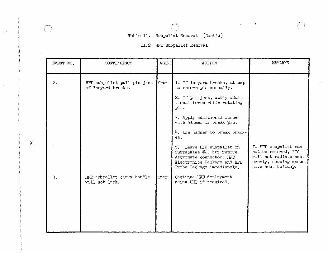
EVENT NO.
2.
3.
Table 11. Subpallet Removal (Oont'd)
11.2 HFE Subpallet Removal
CONTINGENCY AGENT
HFE sub pallet pull pin jams I Crew of lanyard breaks.
ACTION
1. If lanyard breaks, attempt to remove pin manually.
2. If pin jams, apply additional force while rotating pin.
3. Apply additional force with hammer or break pin.
4. Use hammer to break bracket.
5. Leave HFE subpallet on Sub package #2, but remove Astromate connector, HFE Electronics Package and HFE Probe Package immediately.
HFE subpallet carry handle will not lock.
Crew I Continue HFE deployment using UHT if required.
REMARKS
If HFE subpallet cannot be removed, RTG will not radiate heat evenly, causing excessive heat buildup.

\Jl LA.>
EVENT NO.
4.
TABLE ll. Subpallet Removal ( Cont 'd)
11.2 HFE Subpallet Removal
CONTINGENCY
HFE subpallet Boyd bolt spline will not depress.
AGENTI ACTION
Crew I l. Check hex head of UHT and, if damaged, use second UHT.
Crew I 2. Use hammer on top of UHT to force depression of Boyd bolt spline.
Crew 3. Attempt to overcome spline lock by forcefully rotating UHT.
Crew I 4. Use hammer to break bracket or strut.
Crew I 5. Leave HFE subpallet on Subpackage #2, but remove Astromate connector, HFE Electronics Package, and HFE Probe Package immediately
REMARKS
If HFE subpallet cannot be removed, RTG will not radiate heat evenly causing excessive heat buildup.

\J1 -r=-
EVENT NO.
5.
TABLE 11. Subpallet Removal (Cont'd)
11.2 HFE Subpallet Removal
CONTINGENCY AGENT ACTION
HFE subpallet Boyd bolt will Crew l. Check hex head of UHT and, not rotate. if damaged, use second UHT.
Crew 2. Attempt to_overcome boyd bolt threads by forcefully rotating mrr.
Crew 3. Use hammer to attempt to break bracket or strut.
Crew 4. Leave HFE subpallet on Sub package #2, but remove Astro-mate connector, HFE Electron-ics Package and HFE Probe Package immediately.
REMARKS
If HFE subpallet can-not be removed, RTG will not radiate heat evenly, causing exces-sive heat buildup.
I !

\Jl \Jl
EVENT NO.
6.
TABLE 11. Subpallet Removal (Oont'd)
11.2 HFE Subpallet Removal
CONTINGENCY AGENT ACTION
HFE subpallet will not come Crew 1. Ensure both Boyd bolts off Subpackage #2. have been released.
Crew 2. Use UHT to ensure that Boyd bolts have been sprung upward.
Crew 3. Ensure that front of subpallet has been rasied to clear the mounting stud.
Crew 4. Use hammer to force for-ward movement of subpallet or to break bracket or strut.
Crew 5. Leave HFE subpallet on Subpackage #2, but remove Astromate connector, HFE Electronics Package, and HFE Probe Package immedi-ately.
Q
REMARKS
i
If subpallet cannot be removed, RTG will not radiate heat evenly, causing exces-sive heat buildup.

\Jl 0\
EVENT NO.
1.
2.
TABLE 11. Subpallet Removal ( Cont 'd)
11.3 Side/CCGE Subpallet Removal
CONTINGENCY
Side subpallet Boyd bolt spline will not depress.
Side subpallet Boyd bolt will not rotate.
AGENT ACTION
Crew I 1. Check hex head of UHT and, if damaged, use second UHT.
Crew I 2. Use hammer on top of UHT to force depression of Boyd bolt spline.
Crew I 3. Attempt to overcome spline lock by forcefully rotating UHT.
Crew
Crew
4. Leave side subpallet on Subpackage #2, but remove Side/CCIG and aiming mechanism immediate~.
1. Check hex head of UHT, and if damaged, use second UHT.
Crew I 2. Attempt to overcome Boyd bolt threads by forcefully rotating UHT.
Crew I 3. Leave side subpallet on Sub package #2, but remove Side/CCIG and aiming mechanism immediate~.
REMARKS
If side subpallet cannot be removed, RTG will not radiate heat evenly, causing excessive heat buildup.
If side subpallet cannot be removed, RTG will not radiate heat evenly, causing excessive heat buildup.

\.Jl -'!
EVENT NO.
3.
TABLE ll. Subpallet Removal ( Cont ' d)
11.3 Side/CCGE Subpallet Removal
CONTINGENCY
Side subpallet will not come off Subpackage #2.
AGENT ACTION
Crew I l. Ensure both Boyd bolts have been released.
Crew 1 2. Use UHT to ensure that Boyd bolts have been sprung upward.
Crew I 3. Ensure that front of side subpallet has been raised 3/8 inch to clear mounting stud.
Crew 4. Kick side subpallet to force forward movement.
Crew I 5. Use hammer to force forward movement of the side subpallet.
Crew 6. Leave side subpallet on Subpackage #2, but remove side/CCIG and aiming mechanism immediately.
REMARKS
If side subpallet cannot be removed, RTG will not radiate heat evenly, causing excessive heat buildup.
\Jl Q)
EVENT NO.
l.
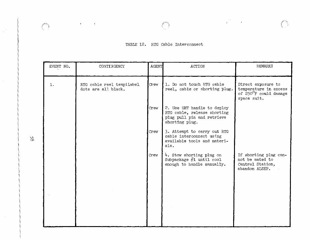
TABLE 12. RTG Cable Interconnect
CONTINGENCY
RTG cable reel tempilabel dots are all black.
AGENTI ACTION
Crew I l. Do not touch RTG cable reel, cable or shorting plug.
Crew I 2. Use UHT handle to deploy RTG cable, release shorting plug pull pin and retrieve shorting plug.
Crew
Crew
3. Attempt to carry out RTG cable interconnect using available tools and materials.
4. Stow shorting plug on Subpackage #1 until cool enough to handle manually.
REMARKS
Direct exposure to temperature in excess of 250°F could damage space suit.
If shorting plug cannot be mated to Central Station, abandon ALSEP.

Vl \0
EVENT NO.
2.
TABLE 12. RTG Cable Interconnect (Cont'd)
CONTINGENCY AGENT ACTION
RTG cable reel Boyd bolts Crew l. Visually check (if cannot be released. possible) to see if bolt is
released and not loose/raised due to side loading.
Crew 2. Check for spring loading on bolt.
Crew 3. Repeat release procedure, i.e., engage depress, rotate ccw 75°.
Crew 4. Insert UHT and apply downward pressure on center spline, Use hammer if necessary, turn ccw to release.
Crew 5. If spline is depressed and bolt will not rotate, back off slightly cw then turn back ccw.
Crew 6. Visually check hex head on UHT and if broken, use second tool.
REMARKS
Exercise caution when working in close proximity to hot RTG.

0\ 0
EVENT NO.
2. (Cont 'd)
TABLE 12. RTG Cable Interconnect (Cont'd)
CONTINGENCY AGENT ACTION
Crew 7. If procedure fails to release bolts, tilt package on carry handle side, and utilize UHT to unwind cable manually to expose shorting plug.
REMARKS
If RTG cable reel cannot be removed, RTG will not radiate heat evenly, causing excessive heat buildup.
I
0\ t-'
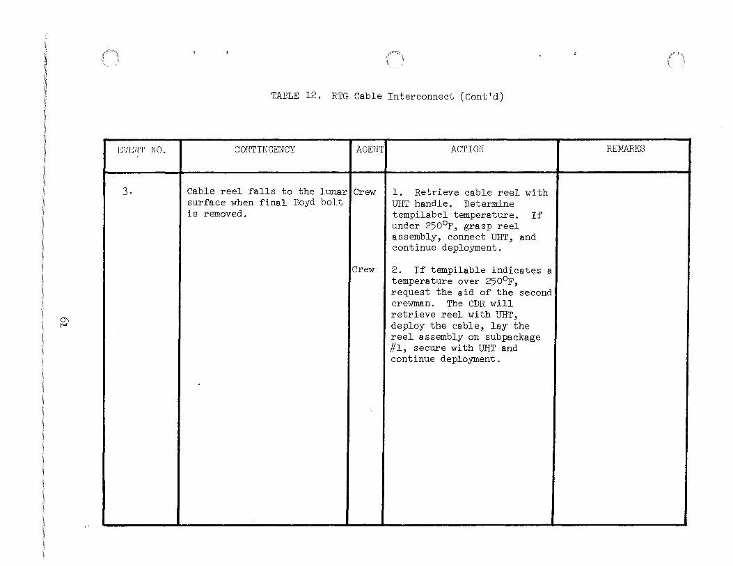
EVENT NO.
3.
TABLE 12, RTG Cable Interconnect (Cont'd)
CONTINGENCY AGENT ACTION REMARKS
Cable reel falls to the lunar Crew 1. Retrieve cable reel with surface when final Boyd bolt UHT handle. Determine is removed. tempilabel temperature. If
under 250°F, grasp reel assembly, connect UHT, and continue deployment.
Crew 2. If tempilable indicates a temperature over 250°F, request the aid of the second crewman. The CDR will retrieve reel with UHT, deploy the cable, lay the reel assembly on subpackage #1, secure with UHT and continue deployment.

0'\ 1\)
EVENT NO.
4.
TABLE 12. RTG Cable Interconnect (Cont'd)
CONTINGENCY AGENT ACTION
Shorting plug pull pin does Crew 1. Apply additional force not release. while rotating pin.
Crew 2. Apply additional force on pin with hammer or break pin.
Crew 3. Use hammer to break bracket.
Crew 4. Attempt to separate cable from shorting switch.
Crew 5. If shorting plug cannot be mated to Central Station, abandon ALSEP.
/
REMARKS
I
If ALSEP deployment is terminated anytime prior to Central Station activation, the .RTG shorting plug reset lanyard will be pulled to assure the RTG is shorted.

0'\ w
EVENT NO.
5 ..
TABLE 12, RTG Cable Interconnect (Cont'd)
CONTINGENCY AGENT ACTION
Shorting plug connector fails Crew l. Check shorting plug to engage and lock to Central connector for proper Station (C/S). orientation.
Crew 2. Check both connectors for debris on pins or Central Station receptacle.
Crew 3. Depress outer flange of shorting plug connector to ensure proper function •
Crew 4. Reconnect applying additional downward pressure on the flange assembly with the LMP helping to provide additional stability (LMP can aid by holding PLSS).
Crew 5. Manually separate the shorting plug from the RTG cable, discard and connect RTG cable directly to Central Station.
REMARKS
If RTG cable connector cannot be mated to Central Station, aban-don ALSEP.

0\ +
EVENT NO.
6.
7.
8.
't \
TABLE l~. RTG Cable Interconnect (Cont'd)
CONTINGENCY AGENT ACTION
Ampere gauge unreadable due I Crew to debris or arrow in ampere
l. Report condition and continue ALSEP deployment.
gauge is at zero (no movement). I Crew 2. Reset the shorting switch
if reading is zero.
Shorting plug depressed but ammeter shows no drop in amperage.
Crew I l. Reset the switch, and redepress.
Crew I 2. Apply additional force to shorting plug and note if amperage drops.
Crew I 3. Disconnect shorting plug from Central Station, separate shorting plug from the RTG cable and connect RTG cable connector to Central Station.
Shorting plug engages, but I Crew falls off when subpackage is rotated.
l. Return subpackage to vertical position, retrieve cable, remove any debris and remate connectors.
Crew I 2. Ensure locking mechanism is fully forward.
REMARKS
Absence of amperage drop is not justification for abandoning ALSEP deployment.

0'\ \Jl
EVENT NO.
l.
2.
TABLE 13. Passive Seismic Experiment
CONTINGENCY
Deploy PSE Stool (Boyd bolt fails to release).
Unable to deploy PSE stool 10 feet west of Central Station.
AGENT
Crew
ACTION
1. Insert UHT and apply downward pressure on center spline. Use hammer if necessary; turn ccw to release.
Crewl 2. If spline is depressed and bolt will not rotate, back off slightly cw then turn back ccw.
Crewl 3. Visually check hex head on UHT, if broken, use second tool.
Crewl 4. Attempt to pry the retainer bracket assembly loose with hammer.
Crew I Locate PSE stool as far from Central Station and other experiments as possible.
REMARKS
The PSE sensor could be placed directly on the lunar surface, if the PSE stool cannot be released. Experiment thermal control and science may be degraded. •~
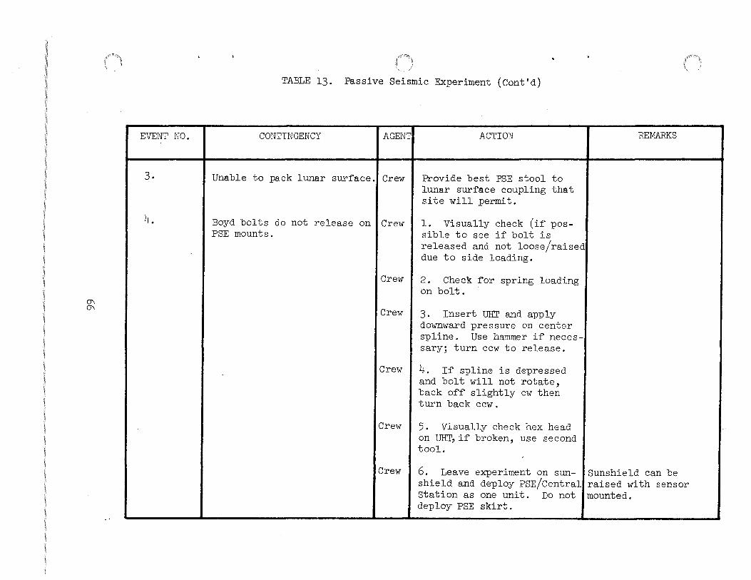
0\ 0\
EVENT NO.
3-
4.
TABLE 13. Passive Seismic Experiment (Cont'd)
CONTINGENCY AGENT ACTION
Unable to pack lunar surface.! Crew Provide best PSE stool to lunar surface coupling that site will permit.
Boyd bolts do not release on I Crew PSE mounts.
l. Visually check (if possible to see if bolt is released and not loose/raised due to side loading.
Crew I 2. Check for spring loading on bolt.
Crew 3. Insert UHT and apply downward pressure on center spline. Use hammer if necessary; turn ccw to release.
Crew I 4. If spline is depressed and bolt will not rotate, back off slightly cw then turn back ccw.
Crew I 5. Visually check hex head on UHT,if broken, use second tool.
Crew 6. Leave experiment on sunshield and deploy PSE/Central Station as one unit. Do not deploy PSE skirt.
REMARKS
Sunshield can be raised with sensor mounted.

0\ -.:J
EVENT NO.
4. (Cont 'd)
5-
TABLE 13.
CONTINGENCY
Passive Seisnrlc Experiment (Cont'd)
AGENT ACTION
Crew I 7. Force cable reel free from retainer bracket and de·· ploy sufficient cable to allow sunshield deployment.
PSE binds on pallet and will I Crew not come off in normal manner! using UHT.
l. Ensure the front portion of the subpallet has been raised (3/8") to clear the mounting stud.
Crew I 2. Apply side loads. Kick with lunar boot (foot) as necessary to eliminate binding.
Crew I 3. Assist the forward movement of the PSE with the lunar boot making sure the mounting stud is clear.
Crew I 4. With the second crewman's help, manually aid in removal by using the back support structure as additional lever.
Crew
Crew
5. Leave PSE on sunshield and deploy PSE/Central Station as one unit. Do not deploy PSE skirt.
6. With UHT, tear away or deploy cable from cable reel.
REMARKS
Experiment thermal control and science data, as well as Central Station thermal control, may be degraded.
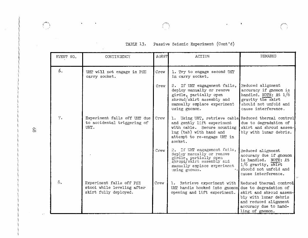
(J'\ co
EVENT NO.
6.
7.
8.
TABLE 13.
CONTINGENCY
UHT will not engage in PSE carry socket.
Experiment ~alls off UHT due to accidental triggering of UHT.
Experiment falls o~~ PSE stool while leveling after skirt fully deployed.
Passive Seismic Experiment (Cont'd)
AGENT
Crew
Crew
Crew
Crew
Crew
ACTION
l. Try to engage second UHT in carry socket.
2. If UHT engagement fails, deploy manually or remove girdle, partially open shroud/ skirt assembly and manually emplace experiment using gnomon.
l. Using UHT, retrieve cable and gently lift experiment with cable. Secure mounting lug (tab) with hand and attempt to re-engage UHT in socket.
2. If UHT engagement fails; deploy manually or remove girdle, partially open sbLQ~d/skirt assembly and manually emplace experiment using gnomon. ·
l. Retrieve experiment with UHT handle hooked into gnomon opening and li~t experiment.
REMARKS
Reduced alignment accuracy i~ gnomon is handled. NOTE: At l/6 gravity t~kirt should not unfold and cause inter~erence.
Reduced thermal control due to degradation o~ skirt and shroud assembly with lunar debris.
Reduced alignment accuracy due i~ .gnomon is handled. NOTE: At l/6 gravity, skirt should not unfold and cause inter~erence.
Reduced thermal control due to degradation o~ skirt and shroud assembly with lunar debris and reduced alignment accuracy due to handling o~ ~oman.
:,-~

~ \.0
EVENT NO.
9.
10.
11.
TABLE 13. Passive Seismic Experiment (Cont'd)
CONTINGENCY AGENT
Thermal shroud will not lay I Crew ~lat at outer edge.
ACTION
Place discarded ALSEP parts and/or lunar rocks on shroud edge.
REMARKS
UHT punctures thermal shroud I Crew during leveling sequence.
Remove UHT ~rom puncture and 'Experiment thermal attempt to cover the opening, control may be degradec i~ the hole remains.
Lunar debris degrades reada- I Crew bility o~ bubble leveling indicator and alignment inde~ on shroud.
1. Level by using the local surface area as a reference (PSE shadow).
Crew I 2. Ensure ample picture coverage is obtained to veri~y experiment orientation.
Improper alignment will result in di~~iculty correlating PSE data tc a position on the lunar sur~ace.
Without + 5° leveling of LP XYZ and tidal sensors, sensors will not operate.

EVENT NO.
l.
2.
-..;) 0
I
3.
TABLE 14. Heat Flow Experiment
14.1 Deployment
CONTINGENCY AGENTi
Astromate connector will not ICrew come out of stowage assembly.
Crew
Crew
J Astromate connector falls to ICrew lunar surface.
I Astromate connector fails to I Crew engage and lock.
I Crew
Crew
Crew
Crew
ACTION
l. Apply additional force.
2. Obtain assistance from second crewman.
3. Use hammer to break bracket.
Retrieve connector with UHT handle.
1. Check connector for proper orientation.
2. Check connectors on cable and Central Station for debris and bent pins.
3. Remove or shake out debris.
4. Ensure flange is free to travel to the lock position.
5. Attempt to reconnect.
REMARKS
If astromate connector cannot be removed from stowage assembly, abandon HFE deployment.
Ensure connector is free of debris.
If astromate connector cannot be mated to Central Station, abandon HFE deployment.

-.:] 1-'
EVENT NO.
4.
5.
6.
TABLE 14. Heat Flow Experiment (Cont 'd)
14.1 Deployment
CONTINGENCY AGENTI ACTION
Astromate connector locking lever fails to rotate and lock.
Crew I 1. Apply additional force.
Crew I 2. Abandon eff9rt to rotate locking lever.
Astromate connector engages, ICrew but f'alls of'f' when subpackage is rotated.
Crew
Unable to deploy heat f'low I Crew experiment electronics thirty f'eet from Central Station
Crew
1. Return subpackage to vertical position, retrieve cable, remove any debris and remate connectors.
2. Ensure locking mechanism is fully forward and locking lever is fully rotated.
l. Deploy electronics as far as possible from the Central Station, staying as far as possible from the RTG.
2. Probe should be placed in bore hole pattern as shown in Figure l.
REMARKS
Primary locking feature should suffice.
The objectives of' this pattern in Figure 1. are to remove the probes as f'ar as possible f'rom the RTG and yet maintain them a distance of approximately 20 f'eet apart.

EVENT NO.
7.
8.
~
9.
TABLE 14. Heat Flow Experiment (Cont'd)
14.1 Deployment
CONTINGENCY
UHT will not engage in HFE carry socket.
HFE falls off UHT.
Crewman walks too far and jerks Central Station.
AGENT
Crew
Crew
ACTION
l. Try to engage second UHT in carry socket.
2. If UHT engagement fails, deploy manually.
Crew I l. Use UHT handle to retrieve cable, gently lift experiment and attempt to re-engage UHT-in socket.
Crew 2. If UHT engagement fails deploy manually.
Crew I l. Carry HFE subpallet back toward Central Station to provide slack cable and continue deployment of HFE.
Crew 2. Check cable and connectors of experiment and Central Station interfaces for visible sign of damage.
REMARKS
Reduced thermal control due to degradaticr. of experiment with lunar dust.
Carry experiment to deployment site by holding the leg.

~ w
EVENT NO.
10.
ll.
TABLE 14. Heat Flow Experiment (Cont'd)
14.1 Deployment
CONTINGENCY AGENT ACTION
HFE subpallet strut will not Crew l. Apply additional force. collapse.
2. Apply additional force with hammer.
Crew 3- Continue HFE deployment with strut uncollapsed.
HFE subpallet falls over on Crew Use UHT handle to hook HFE lunar surface. subpallet carry handle and
properly emplace HFE sub-pallet.
REMARKS
I
I
Reduced thermal con-trol due to degrada-tion of thermal point 1-rith lunar debris.
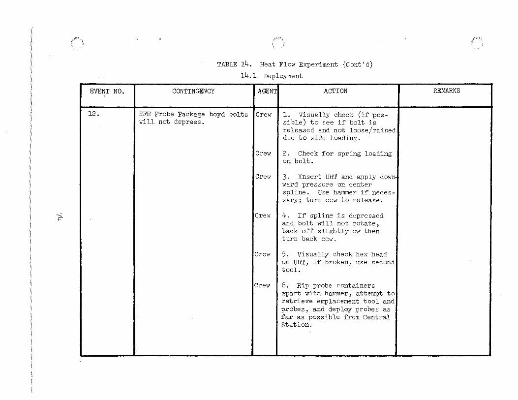
EVENT NO.
12.
"t-
CONTINGENCY
TABLE 14. Heat Flow Experiment (Cont'd)
14.1 Deployment
AGENT; ACTION
HFE Probe Package boyd bolts ICrew will not depress.
l. Visually check (if possible) to see if bolt is released and not loose/raised due to side loading.
Crew I 2. Check for spring loading on bolt.
Crew I 3. Insert UHT and apply down ward pressure on center spline. Use hammer if necessary; turn cc1v to release.
Crew I 4. If spline is depressed and bolt will not rotate, back off slightly cw then turn back ccw.
Crew I 5. Visually check hex head on UHT, if broken, use second tool.
Crew I 6. Rip probe containers apart with hammer, attempt to retrieve emplacement tool and probes, and deploy probes as far as possible from Central Station.
REMARKS

--..;) \J1
EVENT NO.
13.
TABLE 14. Heat Flow Experiment (Cont'd)
14.1 Deployment
CONTINGENCY
HFE Probe Package boyd bolt will not rotate.
AGENT ACTION
Crew 1 l. Check hex head of UHT and, if damaged, use second UHT.
Crew I 2. Forcefully rotate UHT to wipe out boyd bolt threads.
Crew I 3. Use hammer in an attempt to break HFE Probe Package free.
Crew I 4. Attempt to use hammer claw to rip HFE Probe Package apart starting at seams ana retrieve probes and emplacement tool.
Crew I 5. Cover HFE Probe Package with lunar surface debris.
REMARKS
HFE science data will be severely degraded.

-.::J 0\
EVENT NO.
14.
15.
TABLE 14. Heat Flow Experiment (Cont'd)
14.1 Deployment
CONTINGENCY
HFE Probe Package binds on subpallet and will not come off in normal manner using UHT.
AGENT
Crew
Crew
Crew
Crew
Crew
HFE Probe Package halves williCrew not separate.
Crew
Crew
ACTION
1. Ensure all boyd bolts have been released.
2. Use UHT to ensure that Boyd bolts have been sprung upward.
3. Use hammer in an attempt to break HFE Probe Package free.
4. Attempt to use ha~mer claw to rip HFE Probe Package apart starting at seams, and retrieve probes and emplacement tool.
5. Cover HFE Probe Package with lunar surface debris.
1. Apply additional force.
2. Obtain assistance from second crewman and attempt to use hammer claw to rip HFE Probe Package apart at the seams and retrieve probes and emplacement tool.
3. Cover HFE Probe Package with lunar surface debris.
REMARKS
HFE science data will be severely degraded.
HFE science data will be severely degraded.

EVENT NO.
16.
17.
18.
---:] ---:]
19.
TABLE 14. Heat Flow Experiment (Cont'd)
14.1 Deployment
CONTINGENCY AGENT:
Unable to deploy HFE Probe ICrew Package 16 ~eet west or northeast o~ HFE Electronics Package.
HFE Probe Package falls to lunar surface.
Crewman walks too far and jerks HFE Electronics Package.
Crew
Crew
Crew
GAC pip pin on ALSD difficultiCrew to withdraw.
ACTION
Locate HFE Probe Package as far ~rom RTG, Central Station and other surface experiments as possible.
Use UHT to hook handle or carry strap and retrieve HFE Probe Package.
l. Carry HFE Probe Package back toward HFE Electronics Package to provide sufficient slack cable ~or probe emplacement and continue deployment of HFE.
2. Check cable and connector at HFE Electronics Package interface for visible signs o~ damage
Apply side loads to drill using ALSD handle, while exerting removal ~orce on pip-pin.
REMARKS
Orange and black market at 16' on probe cable.

--.;} CJJ
EVENT NO.
20.
TABLE 14. Heat Flow Experiment (Cont'd)
14.1 Deployment
CONTINGENCY I AGENT
Drill not available at ALSEP I Crew site or difficulty in deploy-ing drill.
Crew
Crew
Crew
ACTION
1. Use core stem to make deepest possible hole in the lunar surface.
2. Remove core stem before inserting probes.
3. After removing core stems, insert heat flow probes into hole as far as possible.
4. Should cave-in of hole occur place adapter over bore stem tapered joint and drive in bore stem with hammer into existing hole as far as possible. Adapter should be in the release mode.
REMARKS
Use extreme care when removing core stem, to minimize cave-in of' the hole.
Astronaut should get as close to the open hole as possible; grasp the lower section near its midpoint and insert probe very carefully to prevent cave-in of material.
If more than one section can be buried in this way so that drill stem will remain standing unattended, insert probes to maximum depth possible.
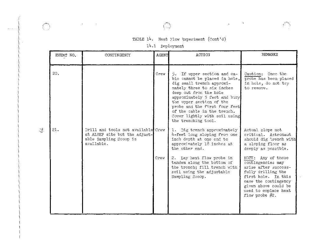
--.:J \.0
EVENT NO.
20.
21.
CONTINGENCY
TABLE 14. Heat Flow Experiment (Cont'd)
14.1 Deployment
AGENT:
Crew
ACTION
5. If upper section and cable cannot be placed in hole, dig small trench approximately three to six inches deep out from the hole approximately 5 feet and bury the upper section of the probe and the first four feet of the cable in the trench. Cover lightly with soil using the trenching tool.
Drill and tools not availableiCrew at ALSEP site but the adjust-
l. Dig trench approximately 4-feet long sloping from one inch depth at one end to approximately 18 inches at the other end.
able Sampling Scoop is available.
Crew I 2. Lay heat flow probe in tandem along the bottom of the trench; fill trench with soil using the adjustable Sampling Scoop.
REMARKS
Caution: Once the probe has been placed in hole, do not try to remove.
Actual slope not critical. Astronaut should dig trench with a sloping floor as deeply as possible.
NOTE: Any of these contingencies may arise after successfully drilling the first hole. In this case the contingency given above could be used to emplace heat flow probe #2.

CD 0
PROBE iff:l
>10 1
FIGURE l.
PROBE 1f2
18'
HFE ELECTRONICS PACKAGE
..... 30'
1-----~.J;S:-1 RTG
CENTRAL STATION
CONTINGENCY DE~LOYMENT PATTERN FOR HFE
N
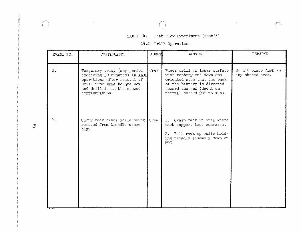
CJ) I-'
EVENT NO.
l.
2.
TABLE 14. Heat Flow Experiment (Cont'd)
14.2 Drill Operations
CONTINGENCY I AGENT
Temporary delay (any period I Crew exceeding 30 minutes) in ALSD operations after removal of drill from MESA torque box and drill is in the stowed configuration.
Carry rack binds while being I Crew removed from treadle assem-bly-.
ACTION
Place drill on lunar surface with battery end down and oriented such that the back of the battery is directed toward the sun (decal on thermal shroud 90° to sun).
l. Grasp rack in area where rack support legs converse.
2. Pull rack up while holding treadly assembly down on HTC.
REMARKS
Do not place ALSD in any shaded area.

co f\)
EVENT NO.
3.
~-
..
CONTINGENCY
TABLE 14. Heat Flow Experiment (Cont'd)
14.2 Drill Operations
AGENT ACTION
Handle assembly fails to lock Crew l. Ensure handle is free of properly to battery. interference.
Crew 2. Check alignment of handle.
Crew 3. Ensure that fixed pin is fully engaged and slap handle to engagement position with additional force.
Crew 4. Request second crewman to depress engagement pin and slap handle to engage-ment position.
Crew 5. With the aid of the second crewman attempt dril-ling operations without the handle.
Crew 6. If unsuccessful use treadle assembly to drive bore stems.
~-----·--------
REMARKS
'
I
'----
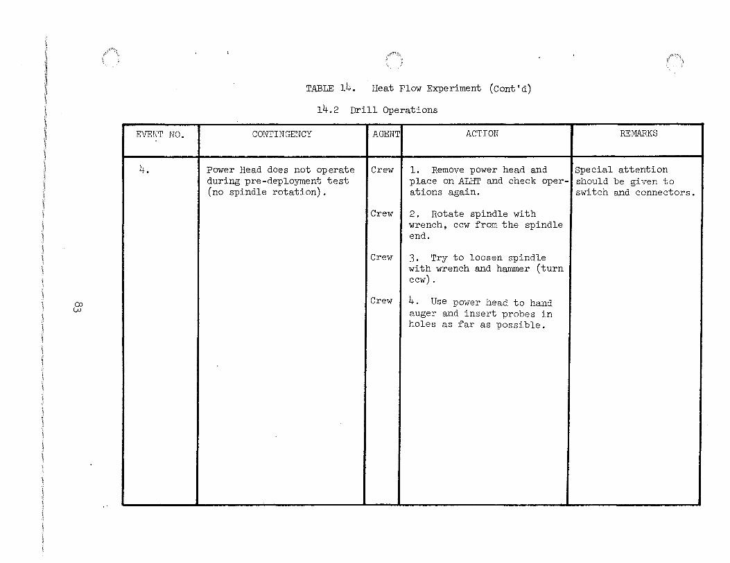
()) lAJ
EVENT NO.
4.
TABLE 14. Heat Flow Experiment (Cont'd)
14.2 Drill Operations
CONTINGENCY AGENT ACTION
Power Head does not operate Crew l. Remove power head and during pre-deployment test place on ALHT and check oper-(no spindle rotation). ations again.
Crew 2. Rotate spindle with wrench, ccw ~rom the spindle end.
Crew 3. Try to loosen spindle with wrench and hammer (turn ccw).
Crew 4. Use power head to hand auger and insert probes in holes as ~ar as possible.
REMARKS
Special attention should be given to switch and connectors.

co +
EVENT NO.
5.
6,
TABLE 14. Heat Flow Experiment (Cont'd)
14.2 Drill Operations
CONTINGENCY AGENT ACTION
ALSD operations are inter- Crew l. Replace thermal shroud. rupted after drill deployment Place power head and battery from stowage configuration assembly into MESA. Properly and drilling commenced. reposition MESA blankets.
Crew 2. If not feasible to place power head and battery into MESA then replace thermal shroud and place drill on lunar surface with battery end down and oriented such that the back of the battery is oriented toward the sun 0 (decal on thermal shroud 90 to sun).
Power head bracket jams Crew Grasp spindle with left hand causing difficulty in removal and press down on treadle from the treadle. with thumb.
---- ~~~ '---------- - - - •- -
REMARKS
Do not place ALSD in in shaded area.
-

(X) \Jl
EVENT NO.
7.
~~
TABLE 14. Heat Flow Experiment (Cont'd)
14.2 Drill Operations
CONTINGENCY AGENT ACTION REMARKS
Difficulty in drilling hole Crew 1. If drilling rate is<::: with first two sections. 5 in./min., remove drill
and move 3 feet to new location.
Crew 2. If unsuccessful, repeat Step 1 up to 2 new locations.
Crew 3- If unsuccessful at third If crewman is drilling location, continue drilling on first hole then until 10 minutes power-on- proceed to second hole time has elapsed. after completing Step
#3. If drilling on second hole, proceed to coring operation after completion of step #3.
---~~---- -------

EVENT NO.
8.
CP I I 0\
CONTINGENCY
TABLE 14. Heat Flow Experiments (Cont'd) 14.2 Drill Operations
AGENT: ACTION
Unable to add additional steml Crew sections due to adapter not releasing.
l. Set adapter to release mode and check visually to see that adapter is set correctly.
Crew
Crew
2. Apply power to drill to force release of stems.
3. Drill hole to minimum handle height.
Crew I 4. Break stem off using inspect
1 I ~~:;~e~~ad and
Crew 5. Assure that taper ,joint inside
Crew
does not remain adapter.
6. If unsuccessful in cleaning adapter, proceed to coring operation.
REMARKS
If part of stem remains inside adapter, use end of wrench to clean adapter.

CD -..::]
EVENT NO.
9.
TABLE 14. Heat Flow Experiment (cont'd)
14.2 Drill Operations
CONTINGENCY
Unable to drill success~ully with new stem sections.
AGENTI ACTION
Crew I 1. Remove power head and check visually ~or damaged male or ~emale taper joints.
Crew I 2. I~ damaged, attempt to remove damaged section and replace with new stem section.
Crew I 3. I~ unable to remove damaged section, replace power head and drill hole to minimum handle height.
REMARKS
A damaged male taper on top section vmuld be indicated by non-rotation o~ stem.
Crew I 4. Remove power head and i~ I Proceed to second hole male taper joint is damaged, or coring operation. insert handle of wrench and clean out the damaged taper joint.

co co
EVENT NO.
10.
CONTINGENCY
TABLE 14. Heat Flow Experiments (Cont'd)
14.2 Drill Operations
AGENT ACTION
Adapter contaminated with Crew l. Tap lightly to remove de-lunar debtis. bris, cycle by hand several
times to assure rree movement
Crew 2. Ir adapter is separated from power head, adjust re-taining clips, replace care-fully and repeat step 1.
Crew 3. If unsuccessful in re-moving debris, use short burst of power to aid in cleaning erfort.
Crew 4. If lunar debris remains, use lunar dust brush rirst and then use lens brush to more thoroughly clean adapter.
REMARKS

co \0
EVENT NO.
11.
12.
TABLE 14. Heat Flow Experiment (Cont'd)
14.2 Drill Operations
CONTINGENCY AGENT ACTION
High torque exists during Crew 1. Leave power head oper-drilling operations. ating and lift repeatedly
until torque decreases.
Crew 2. If unsuccessful, continue drilling.
Power head runs slowly. Crew 1. Tap relief valve with hammer or wrench.
Crew 2. If unsuccessful, use hand auger and apply power only when necessary.
REMARKS
Slip clutch will pre- , vent excessive torque j
from over-powering astronaut.

EVENT NO.
l.
'8
TABLE 14. Heat Flow Experiment (Cont'd)
14.1 Probe Emplacement
CONTINGENCY
Possible to drill only a shallow bore hole.
AGENT:
Crew
ACTION
1. I~ bore stems are drilled into the lunar sur~ace and will remain standing unattended, emplace heat ~low probes into bore hole as ~ar as possible.
Crew I 2. Make care~ul measurement with the emplacement tool to determine the depths o~ hole and depth o~ probe emplacement.
Crew 3. I~ less than two sections o~ bore stem are drilled into the lunar sur~ace and drill string will not stand unattended, use available tools to make deepest possible hole and emplace probes into bore hole as ~ar as possible.
REMARKS
Re~er to contingency action outlined in Section 14.1, Event 21
Crew I 4. Cover any exposed area o~~ At least the ~irst the probes and cable with ~our ~eet o~ cable lunar soil. should be buried.

\D 1-'
EVENT NO.
2.
TABLE 14. Heat Flow Experiment (Cont'd)
14.3 Probe Emplacement
CONTINGENCY AGENT ACTION
Heat flow emplacement tool Crew l. Rotate unlocked section sections do not lock in and attempt to lock, apply extended position. additional force.
Crew 2. Restow unlocked section and attempt to lock again by applying additional force.
Crew 3. If only one section is inoperative, continue to use as is.
Crew 4. Insert probe with cable as deep as possible.
--
REMARKS
HFE science data may be degraded.
.

EVENT NO.
3·
4.
'lB
TABLE 14. Heat Flow Experiment (Cont 'd)
14.3 Probe Emplacement
CONTINGENCY AGENT
Emplacement tool collapses ICrew while driving probe into bore hole.
Crew
Obstructions in the bore ICrew stem prevent probe from being inserted complet~ly.
Crew
Crew
ACTION
1. Withdraw emplacement tool re-extend and lock emplacement tool and resume driving probe into bore hole.
2. If emplacement tool collapses again, insert probe into bore hole as far as possible and report collapse of tool.
l. Use the emplacement tool to attempt to clear obstruction from the hole.
2. Emplace brobe in bore hole.
3. If unsuccessful, repeat Steps l and 2 until able to emplace probe.
REMARKS
HFE science data may be degraded.
Caution: Exercise care when removing probes. Probes can safely be pulled with a force up to 30 lbs.
Note: The most like lyl cause of an obstruction in the bore stem is that one of the male taper joints has been peened over so that filaments of glass project into the center portion of the bore stem.
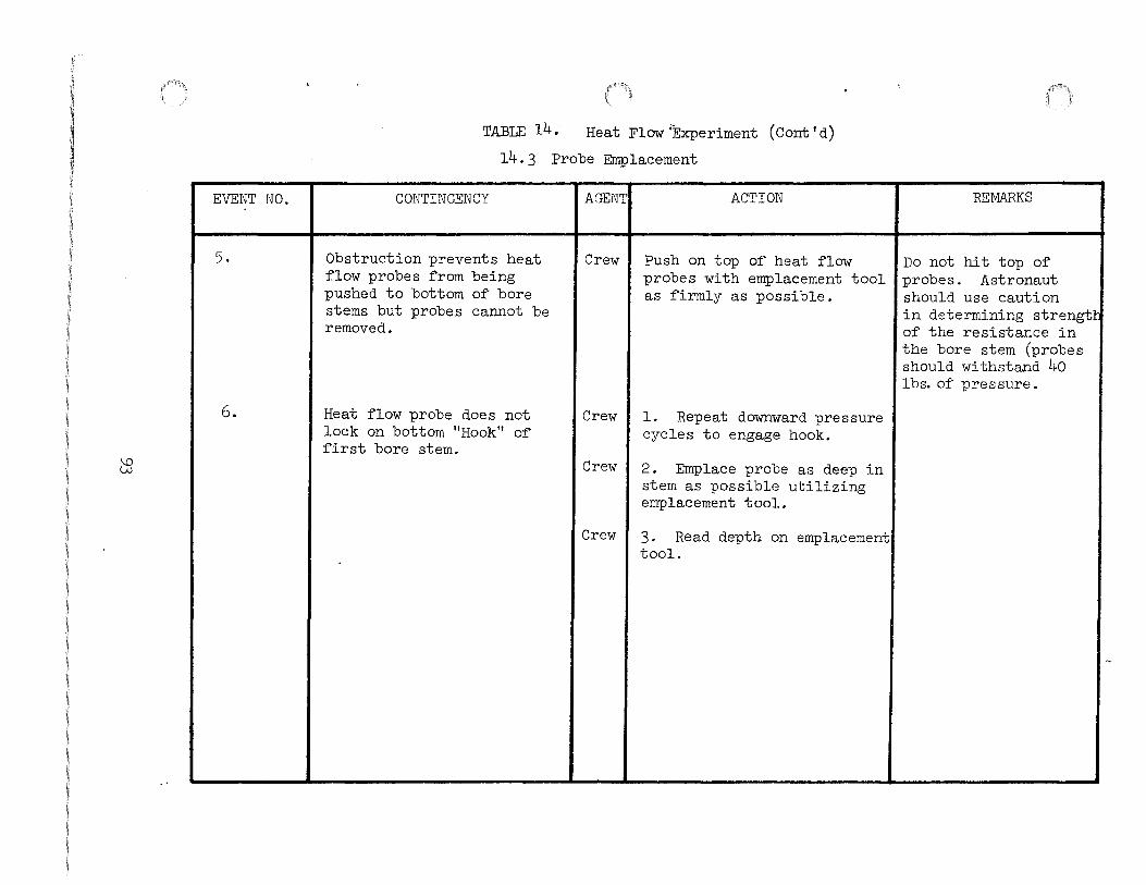
EVENT NO.
5.
6.
CB
TABLE 14. Heat Flow'Experiment (Cont'd)
14.3 Probe Emplacement
CONTINGENCY AGENT ACTION
Obstruction prevents heat Crew Push on top of heat flow flow probes from being probes with emplacement tool pushed to bottom of bore as firmly as possible. stems but probes cannot be removed.
Heat flow probe does not Crew l. Repeat downward pressure lock on bottom "Hook" of cycles to engage hook. first bore stem.
Crew 2. Emplace probe as deep in stem as possible utilizing emplacement tool.
Crew 3. Read depth on emplacement tool.
REMARKS
Do not hit top of probes. Astronaut should use caution in determining strength of the resistance in
1
the bore stem (probes should withstand 4o lbs. of pressure.

\() +
EVENT NO.
l.
2.
0
TABLE 14. Heat Flow Experiment (Cont'd)
14.4 Core Operations
CONTINGENCY
Core sections do not engage at male/female connections.
Power head will not couple to core stem.
AGENT
Crew
Crew
ACTION
1. Check axial alignment and attempt rearrangement.
2. Inspect male joint for foreign material and clean.
REMARKS
Crew I 3. Attempt to add new stem sections and repeat Steps l and 2 until engagement.
Crew I 4. If unsuccessful in mating,Aid of second crewman by hand, use wrench for is necessary.
Crew
Crew
Crew
additional torque.
l. Hold power head spindle to the core stem and rotate the power head until full thread engagement is achieved
2. If unsuccessful, use new core stems (6 stems available) and repeat step l until engagement is achieved.
Care should be exercised to assure proper axial alignment.
Consult P.I. before abandoning coring operations.
3. If unsuccessful in mating,Aid of second crewman by hand, use wrench for is necessary. additional torque.

\0 Vl
EVENT NO.
3.
TABLE 14. Heat Flow Experiment (Cont'd)
14.4 Core Operations
CONTINGENCY AGENT ACTION
Core bit will not pass Crew l. Hold stem and rotate through treadle lock. treadle assembly ccw with
foot using wrench if neces-sary. (Start of coring oper-at ion.)
Crew 2. Remove power head, place treadle lock over the top of stem assembly and replace power head.
Crew 3. (End of Coring Operation) Remove power head from core stem, attempt to remove treadle lock over top of male joint.
---~ --------
REMARKS
Assure male joint is free from foreign material.

\D 0\
EVENT NO.
4.
CONTINGENCY
TABLE 14. Heat Flow Experiment (Cont'd)
14.4 Core Operations
AGENT ACTION
Core stem cannot be unscrewedl Crew from power head spindle.
1. Turn and lift stems to attempt to set treadle lock.
Crew I 2. If unsuccessful, use wrench to hold core stem and
•- I decouple.
Crew I 3. If unsuccessful, tap stem spindle interface with hammer and repeat step 2.
Crew I 4. If unsuccessful, retract stem until second joint is exposed, remove power head with first stem attached, and continue coring operation by adding core stems at this interface.
REMARKS
Aid of second crewman needed.
If successful, inspect and clean exposed male joint and consult P.r. concerning cleaning of female joint.

\() --.::]
EVENT NO.
5.
6.
7.
TABLE 14. Heat Flow Experiment (Cont'd)
14.4 Core Operations
CONTINGENCY
Power head spindle binds on male end o~ core stem a~er drilling.
Core stems do not disengage at male/~emale connections.
AGENTI ACTION
Crew I l. Cradle handle assembly between thumbs and ~ore~ ~ingers and li~ up and ~orward.
Crew I 2. Use wrench to decouple power head and core stem and repeat Event l, Steps l and 2.
Crew I 3. Use hammer impact ~orce to ~ree binding.
Crew I 1. Use treadle as additional torque.
Crew I 2. Tap inter~ace with hammer and repeat Step l.
Crew I 3. Bypass joint and attempt disengagement at next core joint.
Core stem vice jaws on LRV ICrew a~ pallet ~ails or support-
Use treadle core stem lock and ALSD wrench to separate core stems. ing structure ~ails.
REMARKS
Align power head vertically.
Aid o~ second crewman is necessary.
Consult P.r. about status o~ double length core stem.

\0 ())
EVENT NO.
l.
TABLE 15. Lunar Sur~ace Magnetometer Experiment
CONTINGENCY AGENT ACTION REMARKS
Boyd bolts do not release on I Crew LSM mounts.
1. Visually check (i~ possible) to see i~ bolt is released and not loose/raisedl due to side loading.
Crew
Crew
2. Check for spring loading on bolt.
3. Insert UHT and apply downward pressure on center spline. Use hammer i~ necessary; turn ccw to release.
Crew I 4. I~ spline is depressed and bolt will not rotate, back of~ slightly cw then turn back ccw.
Crew I 5. Visually check hex head on UHT, i~ broken, use second tool.
Crew I 6. Leave experiment on sun- ISunshield can be shield and deploy LSM/Central raised with sensor Station as one unit. mounted.
Crew I 7. Force cable reel ~ree ~rom retainer bracket and deploy su~~icient cable to allow sunshield deployment.

\0 \0
EVENT NO.
2 .
..
TABLE 15. Lunar Sur~ace Magnetometer Experiment (Cont'd)
CONTINGENCY AGENT ACTION REMARKS
upper support bracket handle Crew 1. Use the UHT to pry handle does not deploy. into the upright position
~or grasping.
Crew 2. Apply tension to the cen-ter lanyard with glove or UHT to release "pip pinn at the Electronic Gimbal Flip Unit.
Crew 3. I~ success~ul, apply The ~orward bar bracket tension to other two lanyards upper and lower sec-to release "A" ~rame swing tions can be separated brackets ~rom the Electronic later a~ter removal Gimbal Flip Unit. ~rom subpackage #1.
Crew 4. Use hammer in an attempt to break bracket.
Crew 5. Leave LSM on.sunshield Experiment thermal and deploy LSM/Central Statiar. control and science as one unit. data, as well as
Central Station thermal control, may be degraded.

EVENT NO.
3-
I 1-' 0 0
4.
TABLE 15. Lunar Surface Magentometer Experiment (Cont'd)
CONTINGENCY AGENTI ACTION I REMARKS
LSM binds on pallet and will Crewl 1. Check center lanyard and not come off in normal manner if untied or broken, there is using UHT. no means of unlocking from
the mounting pins.
Crew I 2. If lanyard is intact, pry under the Electronic Gimbal Flip Unit handle to erfect unlocking.
Crew I 3. If unlocked, but binding
I I on mounting pins, attempt to
f pry under rear of the Elec-tronic Gimbal Flip Unit with the UHT.
Crew I 4. Leave LSM on sunshield 'Experiment thermal con-and deploy LSM/Central Sta- trol and science data, tion as one unit. as well as Central sta-
Crew I 5. tion thermal control,
Force cable reel free I may be degraded. from retainer bracket and deploy sufficient cable to allow sunshield deployment.
I UHT will not engage in LSM I Crewl 1. Try to engage second UHT carry socket. in carry socket.
Crewl 2. If UHT engagement fails, deploy LSM manually.

1-' 0 1-'
EVENT IJO.
5.
6.
7.
TABLE 15. Lunar Surface Magnetometer Experiment (Cant' d)
CONTINGENCY AGENT ACTION REMARKS
Experiment falls off' UHT Crew l. Use UHT handle to re- Reduced thermal control due to accidental triggering trieve cable, gently lift due to degradation of' of' UHT release mechanism. experiment and attempt to experiment with lunar
re-engage UHT in socket. dust.
I Crew 2. If UHT engagement fails, I
deploy manually.
Unable to deploy legs. Crew l. If' spring-loaded legs do not self-deploy af'ter removal of' forward bracket, assist their deployment by hand.
CrevJ 2. Emplace experiment on Experiment stability local surface with legs in will be degraded. stowed position and prop up with rocks or debris to pro-vide the best possible level-ing.
Crew 3. As a last resort, lay the Electronic Gimbal Flip Unit flush on the lunar surface and attempt leveling.
UHT punctures thermal shroud Crew Remove UHT from puncture Experiment thermal during leveling sequences. and at~empt to smooth thermal control may be de-
surface. graded.

t-' 0 f\.)
EVENT NO.
8.
9·
TABLE 15. Lunar Sur~ace Magnetometer Experiment (Cont'd)
CONTINGENCY AGENT ACTION REMARKS
LSM tips over on booms Crew l. Attempt to pick up exper- Reduced thermal control while emplacing experiment. iment with UHT. due to degradation o~
experiment with lunar dust.
Crew 2. Grasp experiment by boom and reinsert UHT.
I
Crew 3. Clean experiment with I thermal glove.
Lunar debris degrades reada- Crew l. Level by using the local Improper alignment will bility o~ bubble leveling sur~ace area as a re~erence result in dif~iculty indicator and alignment index (LSM shadow). correlating data to a on shroud. position on the lunar
surface.
Crew 2. Ensure ample picture coverage is obtained to veri~y experiment orienta-tion.
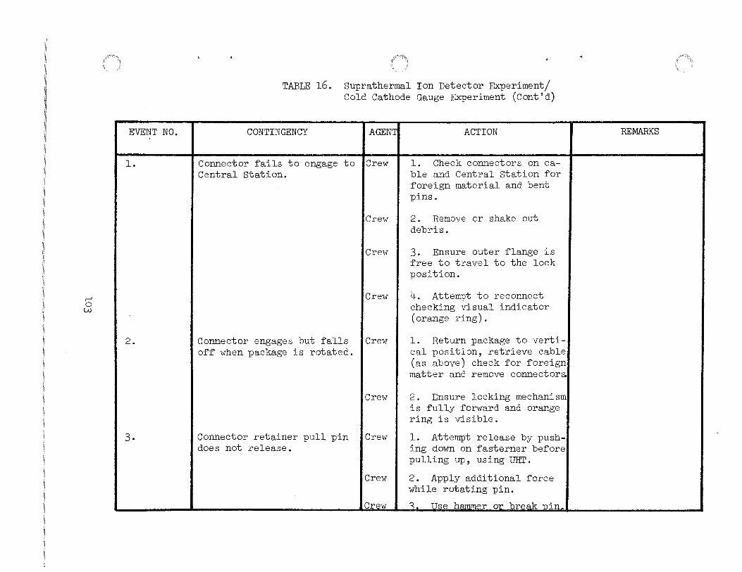
1-' 0 w
EVENT NO.
l.
2.
3.
TABLE 16. Suprathermal Ion Detector Experiment/ Cold Cathode Gauge Experiment (Cont'd)
CONTINGENCY AGENT:
Connector fails to engage to ICrew Central Station.
Crew
Crew
Crew
Connector engages but falls ICrew off when package is rotated.
Connector retainer pull pin does not release.
Crew
Crew
Crew
Ierew
ACTION
1. Check connectors on cable and Central Station for foreign material and bent pins.
2. Remove or shake out debris.
3. Ensure outer flange is free to travel to the lock position.
4. Attempt to reconnect checking visual indicator (orange ring) .
l. Return package to vertical position, retrieve cable (as above) check for foreign matter and remove connector&:
2. Ensure locking mechanism is fully forward and orange ring is visible.
l. Attempt release by pushing down on fasterner before pulling up, using UHT.
2. Apply additional force while rotating pin.
~. TT.c:e hammer or break Pin
REMARKS
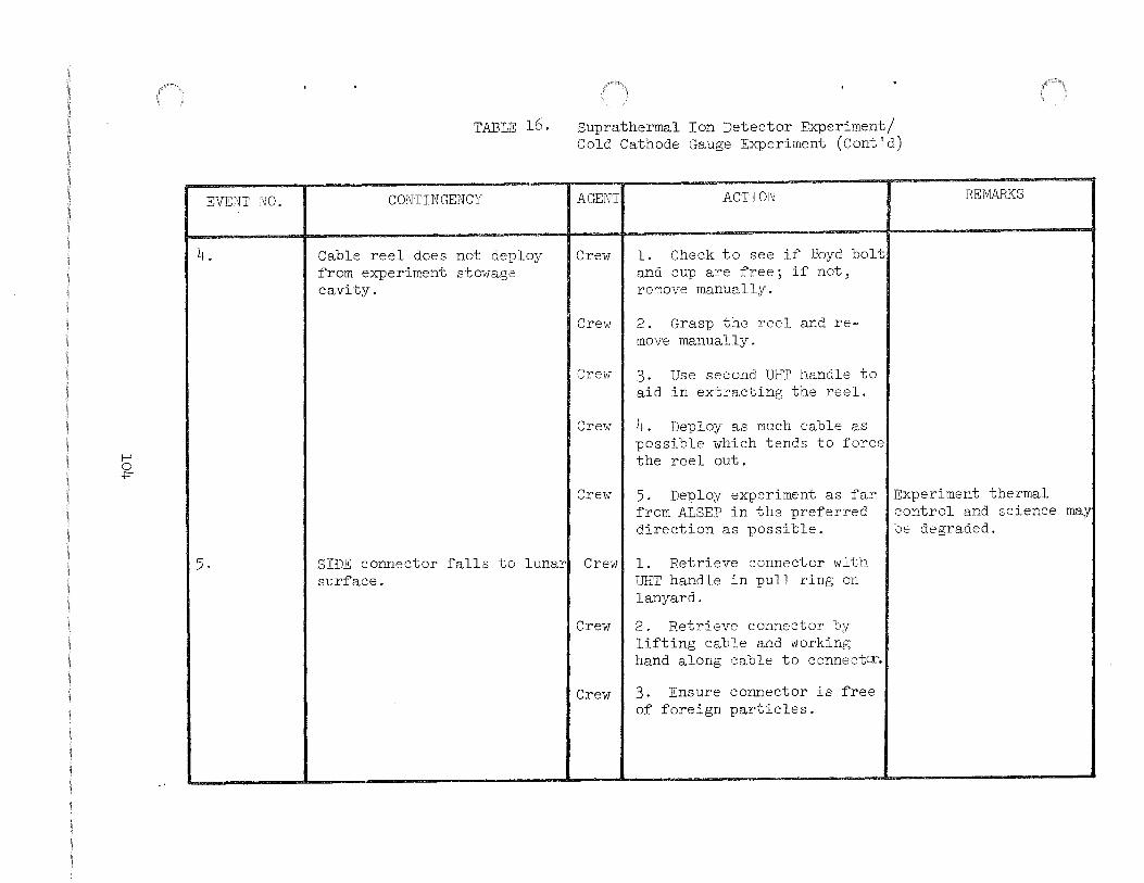
EVENT NO.
4.
I I !--' 0 +
I I
5.
TABLE 16. Suprathermal Ion Detector Experiment/ Cold Cathode Gauge Experiment (Cont'd)
CONTINGENCY
Cable reel does not deploy from experiment stowage cavity.
I I
AGENT
Crew
Crevv
Crew
Cre1v
Crew
ACTION
l. Check to see if Boyd bolt and cup are free; if not, remove manually.
2. Grasp the reel and remove manually.
3. Use second UHT handle to aid in extracting the reel.
4. Deploy as much cable as possible which tends to force the reel out.
5. Deploy experiment as far from ALSEP in the preferred direction as possible.
SIDE connector falls to lunarl Crew' l. Retrieve connector with surface. UHT handle in pull ring on
lanyard.
Crew I 2. Retrieve connector by lifting cable and working hand along cable to connectoc.
Crew 1 3. Ensure connector is free of foreign particles.
REMARKS
Experiment thermal control and science may be degraded.

I-' 0 \Jl
EVENT NO.
6.
7.
8.
TABLE 16. Suprathermal Ion Detector Experiment/ Cold Cathode Gauge Experiment (Cont'd)
COl\JTINGENCY AGENT
UHT will not engage in SIDE/ I Crew CCGE carry socket.
Crew
Experiment :falls o:f:f ill-IT due I Crew to accidental triggering o:f UHT release mechanism.
Crew
Crewman walks too :far and I Crew jerks Central Station out o:f alignment.
ACTION
l. Try to engage second UHT in carry socket.
2. I:f illfr engagement :fails, deploy manually by grasping back support structure or tool brackets.
1. Use li1T handle to retrieve cable, gently li:ft experiment, manually secure ground screen tube or leg and attempt to re-engage UHT in socket.
2. I:f UHT engagement :fails, deploy manually by grasping ground screen tube.
1. Carry experiment back toward Central Station to provide slack cable, continue deployment o:f SIDE/CCGE and realign Central Station and check other experiments upon return.
Crew I 2. Check cable and connector at experiment and Central station inter:faces :for visible signs o:f damage.
REMARKS

t--' 0 0\
EVENT NO.
9.
10.
TABLE 16. Suprathermal Ion Detector Experiment/ Cold Cathode Gauge Experiment (Cont'd)
CONTINGENCY
UHT will not disengage from SIDE subpallet UHT socket.
SIDE/CCGE will not come off subpallet.
AGENT
Crew
Crew
Crew
Crew
Crew
Crew
ACTION
l. Apply additional force.
2. Obtain assistance from second crevnnan.
3. If UHT will not disengage, leave it on the SIDE subpallet and continue deployment using second UHT.
1. Ensure all boyd bolts have been released.
2. Use UHT to ensure that boyd bolts have been sprung upward.
3. Leave SIDE/CCGE on subpallet and deploy SIDE/CCGE subpallet. Remove ground screen and discord.
REMARKS
SIDE subpallet stability will be degraded. Although only; one UHT is needed for deployment, deployment time will be increased Second crewman could carry out geological tasks while first .. astronaut completes ALSEP deplo~nent.
Experiment thermal control and science may be degraded.

I-' 0 ----:}
EVENT NO.
11.
12.
TABLE 16.
CONTINGENCY
Unable to deploy legs.
UHT will not engage in ground screen socket.
Suprathermal Ion Detector Experiment/ Cold Cathode Gauge Experiment (Cont'd)
AGENT ACTION
Crewl 1. If lanyard breaks, attempt to remove pin manually.
Crewl 2. Emplace experiment on lunar surface with legs in a stowed position.
Crewl 1. Attempt to release ground screen with UHT and to remove and deploy ground screen manually.
Crewl 2. Try to engage second UHT in ground screen socket.
REMARKS
Experiment stability may be degraded.
Crewl 3. If unsuccessful, continueiSIDE science will be SIDE/CCGE deployment without degraded. ground screen.

1-' 0 CD
EVENT NO. .
13.
TABLE 16.
CONTINGENCY
Ground screen will not dis-engage from UHT with trigger during screen deploy-ment.
Suprathermal Ion Detector Experiment/ Cold Cathode Gauge Experiment (Cont'd)
AGENT ACTION REMARKS
Crew l. Manually remove screen from UHT.
Crew 2. Deploy screen manually and drop on the lunar surface as flat as possible.
Crew 3. If UHT will not disengage, Loss of one tWIT will leave it on the screen and increase deployment continue deployment using time. Second crewman second UHT. could carry out geo-
logical tasks while first crewman com-pletes ALSEP deploy-ment.
-~ ---------- ----- ~----------------------

1-' 0 \D
EVENT fW.
14.
15.
·----------- ----- --------
TABLE 16.
CONTINGENCY
SIDE falls over while em-placing experiment.
SIDE leg breaks.
--
Suprathermal Ion Detector Experiment/ Cold Cathode Gauge Experiment (Cont'd)
AGENT ACTION REfVlARKS
Crew l. Attempt to pick up exper- Reduced thermal control iment by cable after re- due to degradation of trieving cable with UHT. experiment with lunar
dust.
Crew 2. Grasp experiment at reel housing and reinsert utiT.
Crew 3. Clean experiment with thermal glove or through gentle impact.
Crew l. Prop experiment on RTG Place ground screen cable reel, rock, or other beside experiment (not lunar debris. touching SIDE or CCGE).
Experiment thermal con-trol may be degraded.
~-----------~----· ----- ---~ ---· ----- ~-L_ ___
I
I

1-' 1-' 0
EVENT NO.
16.
17.
TABLE 16. Suprathermal Ion Detector Experiment/ Cold Cathode Gauge Experiment (Cont'd)
CONTINGENCY
CCGE Boyd bolt jams or will not rotate.
Beutsch fastener will not rotate.
AGENT ACTION
Crew I l. Check hex head of UHT and, if damaged, use second UHT.
Crew I 2. Forcefully rotate UHT to wipe out boyd bolt threads.
Crew
Crew
3. Leave CCGE in stowage cavity and continue SIDE deployment.
l. Check hex head of UHT and if damaged, use second illiT.
Crew I 2. Forcefully rotate UHT to wipe out Deutsch fastener.
Crew I 3. Use UHT or MESA tools to pry or fail retention bracket in an attempt to gain access to CCGE.
Crew 4. Deploy SIDE/CCGE as one unit.
REMARKS
Loss of CCGE will not interfere with successful operation of SIDE.
Loss of CCGE will not interfere with successful operation of SIDE.

f-' f-' f-'
EVENT NO.
18.
19·
20·
21·
TABLE 16. Suprathermal Ion Detector Experiment/ Cold Cathode Gauge Experiment (Cont'd)
CONTINGENCY
CCGE cannot be removed from stowage cavity.
CCGE cannot be attached to ground screen tube.
AGENT
Crew
Crew
Crew
Crew
Crew
Dust cover releases when pulU Crew pin is removed.
Dacron dust bag does not comcl Crew free.
ACTION
1. Ensure that CCGE Boyd bolt is not preventing CCGE removal.
2. Use second UHT to aid in extracting CCGE.
3. Pull on cable in order to force the CCGE out of the cavity.
4. Leave CCGE in stowage cavity and continue SIDE deployment.
Deploy CCGE by using the J
cable instead of the fixed deployment tube.
Deploy with cover open, but minimize dust contamination.
Manually lift experiment and remove dacron bag.
REMARKS
Experiment thermal control science may be degraded.

1-' 1-' 1\)
EVENT NO.
22.
23.
24.
TABLE 16. Suprathermal Ion Detector Experiment/ Cold Cathode Gauge Experiment (Cont'd)
CONTINGENCY AGENT ACTION
SIDE/CCGE connector pull pin I Crew 11. Apply additional force jams. while rotating pin.
SIDE/CCGE connector falls to lunar surface.
Crew 12. Apply additional force on pin with hammer or break pin.
Crew 13. Use hammer to break bracket.
Crew IRetrieve connector with UHT handle.
SIDE/CCGE connector fails to I Crew 11. Check connector for proper engage and lock. orientation.
2. Check connectors on cable and Central Station for debris and bent pins.
3. Remove or shake out debris.
4. Ensure outer flange is free to travel to the lock position.
5. Attempt to reconnect and check visual indicator (orange ring).
REMARKS
If SIDE/CCGE connector cannot be released, abandon SIDE/CCGE deployment. Ensure concector is free of debris.
If SIDE/CCGE connector cannot be mated to Central station, abandon SIDE/CCGE deployment.

I-' I-' w
,.
EVENT NO.
25.
TABLE 16. Suprathermal Ion Detector Experiment/ Cold Cathode Gauge Experiment (Cont'd)
CONTINGENCY AGENT ACTION
SIDE/ CCGE connector engages Crew. l. Return subpackage to but ~alls o~~ when subpackage vertical position, retrieve is rotated. cable, remove any debris and
remate connectors.
Crew 2. Ensure locking mechanism is ~ully ~orward and orange ring is visible.
REMARKS
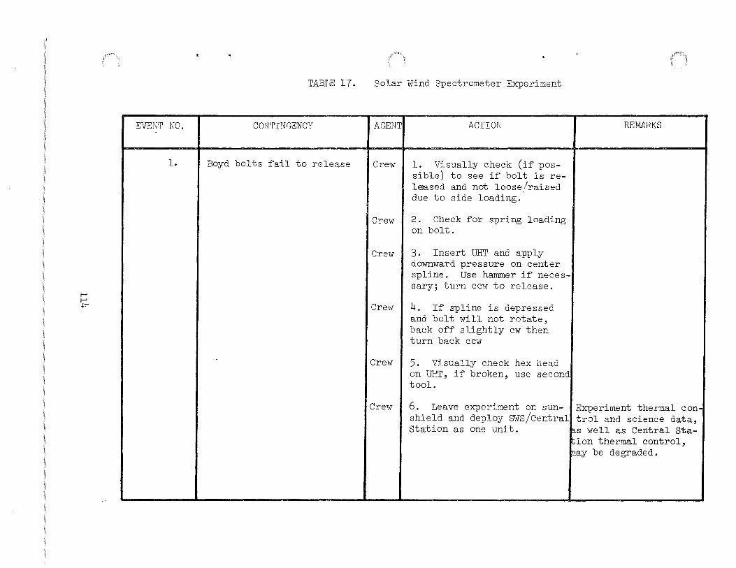
I-' I-' +
EVENT NO.
L
TABLE 17.
CONTINGENCY
Boyd bolts fail to release
Solar Wind Spectrometer Experiment
AGENT
Crew
Crew
Crew
Crew
Crew
Crew
ACTION
1. Visually check (if possible) to see if bolt is released and not loose/raised due to side loading.
2. Check for spring loading on bolt.
3. Insert UHT and apply downward pressure on center spline. Use hammer if necessary; turn cc1v to release.
4. If spline is depressed and bolt will not rotate, back off slightly cw then turn back ccw
5. Visually check hex head on UHT, if broken, use second tool.
REMARKS
6. Leave experiment on sun- ~Experiment thermal conshield and deploy SWS/Central trol and science data, Station as one unit. s well as Central Sta-
ion thermal control, ay be degraded.

I-' I-' V1
EVENT NO.
l. (Cont'd)
TABLE 17. Solar Wind Spectrometer Experiment ( C ont 'd)
CONTINGENCY AGENT ACTION REMARKS
Crew 7. Force cable reel free from If unsuccessful, sun-retainer bracket and deploy shield will not deploy sufficient cable to allow sun- and Central station shield deployment. thermal control will be
degraded. Loss of SWS will not effect the successful operation of remainder of ALSEP.
I
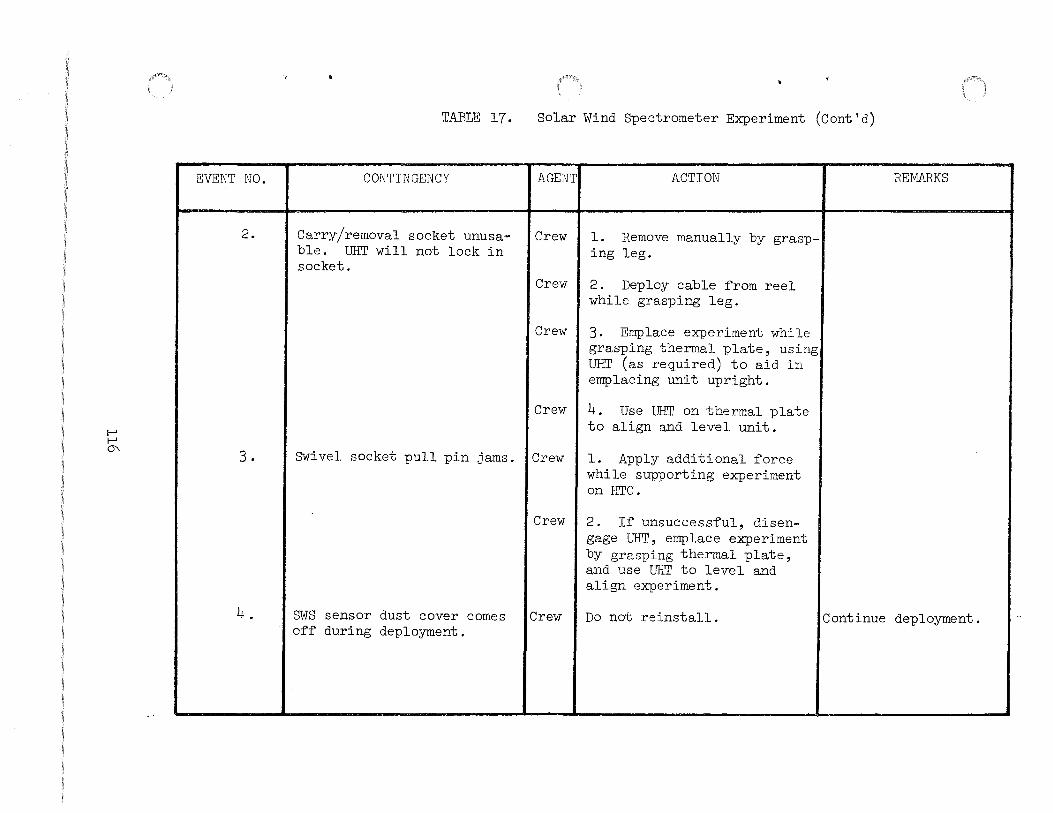
I-' I-' 0\
EVENT NO.
2.
3.
4.
'< 4
TABLE 17. Solar Wind Spectrometer Experiment (Cont'd)
CONTINGENCY
Carry/removal socket unusable. UHT will not lock in socket.
AGENT
Crew
ACTION
1. Remove manually by grasping leg.
Crew I 2. Deploy cable ~rom reel while grasping leg.
Crew I 3. Emplace experiment while grasping thermal plate, using UHT (as required) to aid in emplacing unit upright.
Crew I 4. Use UHT on thermal plate to align and level unit.
Swivel socket pull pin jams. Ierew I 1. Apply additional ~orce while supporting experiment on HTC.
SWS sensor dust cover comes o~f during deployment.
Crew I 2. If unsuccess~ul, disengage UHT, emplace experiment by grasping thermal plate, and use UHT to level and align experiment.
Crew Do not reinstall.
REMARKS
Continue deployment.

I-' I-' -...:J
EVENT NO.
5·
6.
.( . TABLE 17.
CONTINGENCY
Experiment falls off UHT due to accidental triggering of UHT release mechanism.
Unable to deploy SWS 13 feet north of Central Station.
Solar Wind Spectrometer Experiment (Cont'd)
AGENTI ACTION
Crewl l. Use UHT handle toretrieve experiment by hooking the lip of the handle through the "A" frame leg. Grasp the experiment by the top part of the leg and slide the hand up to the bottom of the thermal plate and manually secure experiment. Attempt to reengage UHT in socket.
Crewl 2. If UHT engagement fails, deploy manually.
Crewl l. Locate SWS as far from Central Station as possible.
Crewl 2. Attempt to maintain a 13 foot separation between SWS and Central Station.
Crewl 3. Attempt to maintain at least 10 foot separation between RTG and SWS.
REMARKS
Reduced thermal contrcl due to degradation of experiment with lunar dust.

t-' t-' (X)
EVENT NO.
7·
8.
'I>
TABLE 17.
CONTINGENCY
Unable to deploy legs.
Leg breaks off while em-placing the experiment.
Solar Wind Spectrometer Experiment (Cont'd)
AGENT ACTION REMARKS
Crew l. If leg is sticking at-tempt to pull harder on the foot pad.
Crew 2. Emplace experiment on Experiment stability local rock or debris to pro- will be degraded. vide the best possible leveling.
Crew l. Prop up experiment with Experiment thermal con-core tube, penetrometer, or trol may be degraded. lunar debris, to provide the best possible leveling.

1-' 1-' \0
EVENT iiJO.
l.
TABLE 18.
CONTINGENCY
Boyd bolt(s) fail to release.
Central Station
AGENT
Crew
Crew
Crew
ACTION
l. Visually check (if possible) to see if bolt is released and not loose/raisedl due to side loading.
2. Check for spring loading on bolt.
3. Insert UHT and apply downward pressure on center spline. Use hammer if necessary; turn ccw to release.
Crew I 4. If spline is depressed and bolt will not rotate, back off slightly cw then turn back ccw.
Crew I 5. Visually check hex head on UHT, if broken, use second tool.
Crew I 6. Engage UHT in Subpackage #l temporary stowage socket and use UHT as a lever to raise sunshield.
REMARKS
Crew I 7. Leave sunshield in stowe,Central station thermal condition and attempt to gai control will be de-access to antenna mass graded. bracket.

1-' 1\) 0
EVENT NO.
l. (Cont 'd)
2.
3.
TABLE 18.
CONTINGENCY
sunshield fails to raise after all Boyd bolts are released.
RF antenna cable reel lanyard breaks or pin jams.
Central Station (Cont'd)
AGENT
Crew
Crew
Crew
ACTION
8. If unsuccessful, mount antenna aiming mechanism on sunshield.
l. Engage UHT in temporary stowage socket and raise sunshield manually with UHT as lever arm.
2. Check to see if rear thermal curtain on ALSEP antenna cable is jammed and release it with UHT handle, if required.
Crew I 3. Check to see if curtain covers are marred.
Crew 1 4. If sunshield does not raise, remove curtain retainers and mount antenna mast bracket on the bottom shoe of the structure bracket.
Crew l. Use handle of UHT to engage (hook) restraining brackets and bend/break restraining brackets off the sunshield.
Crew I 2. Deploy cable using UHT.
REMARKS
Antenna aiming accuracy will be degraded.

1-' [\) 1-'
EVENT NO.
4.
5.
TABLE 18. Central Station (Cont'd)
CONTINGENCY AGENT ACTION
UHT will not engage in aimin~Crew mechanism housing carry
l. Try to engage second UHT in carry socket.
socket.
Aiming mechanism Boyd bolts ~ail to release.
Crew
Crew
2. I~ UHT engagement ~ails, deploy manually.
1. Visually check (i~ possible) to see i~ bolt is released and not loose/raised due to side loading.
Crew I 2. Check ~or spring loading on bolt.
Crew I 3. Insert UHT and apply downward pressure on center spline. Use hammer i~ necessary; turn ccw to release.
Crew I 4. I~ spline is depressed and bolt will not rotate, back o~~ slightly cw, then turn back ccw.
Crew I 5. Visually check hex head on UHT, i~ broken, use second tool.
Crew I 6. I~ unsuccess~ul, break housing o~~ mounting legs with side loading to gain access to aiming mechanism.
REMARKS

1-' [\) [\)
EVENT NO.
5. (Cont 'd)
6.
7.
TABLE 18. Central Station (Cont'd)
CONTINGENCY
Antenna mast binds on subpallet taper ~itting.
Aiming mechanism housing will not come o~~ subpallet.
AGENT ACTION
Crew I 7. I~ unable to gain access to aiming mechanism, mount antenna on Central Station sunshield brackets and point antenna toward earth.
Crew I Stand on edge o~ subpallet and rotate mast while applyin€ additional lifting ~orce on lower half.
Crew I l. Ensure both Boyd bolts have been released.
Crew I 2. Use UHT to ensure that Boyd bolts have been sprung upward.
Crew I 3. If unsuccessful, use hammer to break housing off mounting legs in order to gain access to aiming mecha: nism.
Crew I 4. If unable to gain access to aiming mechanism, mount antenna on Central Station sunshield.
REMARKS
Antenna aiming accuracJ will be degraded.
Antenna alming accuracy will be degraded.

~ [\) (JJ
EVENT NO.
8.
9·
10·
TABLE 18. Central Station (Cont'd)
CONTINGENCY
Antenna mast bracket on Central Station covered with lunar debris.
Aiming mechanism ~alls out o~ housing onto lunar sur~ace.
Aiming mechanism knobs will not rotate.
AGENT ACTION
Crew I Clear area with lunar boot or use UHT to probe or jar bracket and ~ree it o~ debris.
Crew I Retrieve mechanism with UHT handle and shake o~~ debris. Clean taper ~itting with glove.
Crew I l. Apply additional ~orce with hand and hammer, being care~ul not to damage mechanism.
Crew I 2. Attempt to intentionally ~ail mechanism, achieve approximately correct orientation using sighting and shll or brace antenna to maintain aiming accuracy.
Crew I 3. Remove antenna mast ~rom Central Station and push it into sur~ace pointing at earth (rough alignment).
REMARKS
Reduced operational capability or jamming o~ the gears and pivot points is possible due to degradation o~ the aiming mechanism sur~aces with lunar debris.

1-' [\)
+
EVENT NO.
10. (Cont 'd)
ll.
TABLE 18. Central Station (Cont'd)
CONTINGENCY
Antenna mast will not seat in bracket on Central Station.
AGENT. ACTION
Crew 14. Adjust as required in real-time communication to capsule communicator.
Crew 11. Examine antenna mast ~or obstructions, dislodge obstructions by impact and reseat antenna mast in bracket in Central Station.
Crew 12. Use hammer to apply additional ~orce.
Crew 13. I~ antenna mast is partially seated, continue with nominal deployment sequence.
Crew 14. I~ antenna mast cannot be seated in bracket or is unstable, mount aiming mechanism and antenna on sunshield.
Crew/15· Adjust antenna and aiming MCC mechanism as required, in
real time, to achieve good communication.
REMARKS
I~ antenna mast cannot be ~ully seated in bracket, the antenna aiming accuracy may be degraded.
Caution: Do not damage aiming mechanism inter~ace.

1--' I\) \Jl
EVENT NO.
12.
TABLE 18.
CONTINGENCY
Aiming mechanism will not seat on antenna mast.
Central Station (Cont'd)
AGENTI ACTION
Crew I l. Examine antenna mast :for obstructions, dislodge obstructions by impact and reseat aiming mechanism on antenna.
Crew I 2. I:f aiming mechanism is partially seated and stable, continue with nominal deployment.
Crew 3. Examine antenna mast :for damage and if damaged, mount aiming mechanism and antenna on sunshield.
REMARKS
I:f aiming mechanism cannot be :fully seated on antenna mast the , antenna aiming accuracy may be degraded.

1-' [\) 0\
EVENT NO.
13.
TABLE 18.
CONTINGENCY
Antenna will not seat on aim-ing mechanism.
Central Station (Cont'd)
AGENT ACTION REMARKS
Crew l. Ensure cable outlet is properly oriented.
Crew 2. Examine antenna and aim-ing mechanism for obstruc-tions, dislodge obstructions by impact and reseat antenna on aiming mechanism.
Crew 3. If antenna is partially but firmly seated on aiming mechanism, continue with nom-inal deployment.
I Crew 4. Examine antenna and aim-
ing mechanism for damage and, if damaged, mount antenna on sunshield.

1--' f\)
.....;]
EVENT NO.
14.
TABLE 18. Central Station (Cant' d)
CONTINGENCY
ALSEP deployment time becomes constrained.
AGENT ACTION
Crew I l. If' antenna is level and aligned, actuate the RTG shorting switch and ASTRO switch No. l.
Crew I 2. If' antenna is not aligned or level and there will be a second EVA, do not actuate these switches.
Crew I 3. If' no second EVA, level and align as accurate as possible and actuate switches.
Crew I 4. Do not activate any switches if' none of' the exper iments have been deployed and no second EVA.
REMARKS

t-' f\)
CD
EVENT NO.
1·
TABLE 19.
CONTINGENCY AGENT
Switch #1 cannot be turned Crew/ cw to ON position. MCC
Crew
Crew
Crew/ MCC
MCC
ALSEP Activation
ACTION REMARKS
l. Report to MCC.
2. Verify that switch is in ccw position.
3. Apply additional force to switch.
4. Report to MCC and con-tinue ALSEP deployment.
5. Compute time when PCU will activate assuming nor-mal RTG warmup, command trans mitter on (Octal 013), con-firm ALSEP data and verify crew to complete ALSEP deployment.

1-' [\)
\.0
EVENT NO.
2.
3.
TABLE 19. ALSEP Activation (Cont'd)
CONTINGENCY
Central Station contingency antenna alignment.
Turn-on of ALSEP transmitter
AGENT ACTION
Crew I l. Point antenna in general direction of earth.
Crew I 2. Adjust antenna pointing angle in small increments, stepping back after each adjustment to avoid distortion of antenna beam pattern.
Crewjl 3. Perform required offsets MCC under MCC direction.
Crev/11. Astronaut standby for MCC manual turn-on of ALSEP
transmitter.
Crew/ 12. Actuate ALSEP back-up MCC switch No. 2 with following
functions:
a. Select Transmitter B. b. Turn on Transmitter. c. Reset receiver circuit
breaker. d. Select and turn on data
processor Y.
REMARKS
Initiate command CD-4 (octal 015) "Transmitter B Select." If no response, advise astronaut via voice link to turn on transmitter.
Acknowledge turn-on of transmitter by reception of RF signal from ALSEP.

1--' w 0
EVENT NO.
3. (Cont 'd)
CONTINGENCY
TABLE 19. ALSEP Activation (Cont'd)
AGENT ACTION
Crew/13· Advise MCC via voice link MCC back-up switch No. 2 has been
actuated.
Crew 14. Acknowledge MCC transmitter message via voice link.
Crew I 5. If transmitter is not functioning, actuate ALSEP back-up switch No. 1, permitting PCU to operate on marginal voltage output of RTG.
Crew/1 6. If transmitter is still MCC not functioning, actuate back
up switch No. 3, energizing all experiments, sequentially
Crew/1 7. Advise MCC via voice link MCC that switch No. 3 has been
actuated.
REMARKS
Advise astronaut via voice link whether transmitter is functioning.
Acknowledge back-up switch No. 3 actuation via voice link.
Confirm power turn-on by telemetry indication (channels 12 and 14).
Advise astronauts that all experiments have been turned on via voice link.

t-' w t-'
EVENT NO.
4.
TABLE 19.
CONTINGENCY
MCC reports downlink signal problems.
ALSEP Activation (Cont'd)
AGENT ACTION
Crew I 1. Crew should verify that antenna is properly oriented, Central Station is properly leveled and aligned, and RF cable and connectors are intact.
Crew I 2. Notify MCC if antenna did not require reorientation, leveling or alignment, and if RF cable and connectors are intact.
MCC 3. If antenna is properly oriented, Central Station is leveled and aligned and RF cable and connectors are intact, select Trans "B".
MCC/ ,4. If unsuccessful, notify Crew crew to adjust antenna point
ing angle in small increments under MCC direction and to step back after each adjustment to avoid distortion of antenna beam pattern.
REMARKS

I-' w 1\)
"'
EVENT NO.
4. (Cant' d)
TABLE 19. ALSEP Activation (Cant 'd)
CONTINGENCY AGENT ACTION
MCC 5. Request data through a site with 85 foot antenna.
MCC 6. Select "Low Bit Rate."
Crew/ 7. If signal still too weak MCC to yield useful data, notify
crew to complete remainder of ALSEP deployment.
-
REMARKS
I
NOTE: High Bit Rate data not usable.
---- -

I-' w w
EVENT NO.
5.
'll
TABLE 19.
CONTINGENCY
Downlink frequency so unsta-ble that Manned Space Flight Network (MSFN) receiver can-not synchronize.
..
ALSEP Activation (Cont'd)
AGENT ACTION REMARKS
MCC l. Select redundant trans-rnitter.
MCC/ 2. Select "Low Bit Rate." Crew
MCC/ 3. If signal still unstable, Crew notify crew to complete
remainder of ALSEP deploymen~
I

1-' LU +
EVENT NO.
l.
CONTINGENCY
No LM docking.
TABLE 20. S-Band Transponder (CSM/LM)
AGENT ACTION REMARKS
MCC l. If CSM lunar orbit mission, proceed with CM portion of experiment only.
MCC 2. If CSM lunar flyby mission, scrub all experiment items.
I I
I
______ .._ - ----------

I-' w \Jl
EVENT NO.
1.
2.
3.
4.
5.
.. !I'
TABLE 21. Down-Link Bistatic Radar Observation o:f the Moon
CONTINGENCY
VHF antenna :failure.
VHF ground equipment :failure
Not enough time to per:form a complete pass with S-band and VHF operating simultaneously.
AGENTI ACTION
Crew ISwitch to other VHF antenna. Position sjc so that selected antenna :faces lunar sur:face.
Crew I Scrub VHF position o:f experiment.
Crew I Per:form the experiment :for as much o:f each pass as possible.
S-band 210' dish at Goldstone I Crew I Scrub S-band portion o:f not available.
Unable to determine S-band high-gain antenna pointing.
experiment.
Crew I Per:form the experiment using the S-band omni-directional antenna.
REMARKS
Assumes one antenna :failure.
Special VHF ground equipment located at Stan:ford University.
Two VHF/S-band passes, separated by approximately 20 hours, are planned.

I"-' VJ (]\
EVENT NO.
l.
2.
TABLE 22.
CONTINGENCY AGENT
Subsatellite does not launch. Crew
Earth Orbit MCC
Subsatellite
ACTION REMARKS
Position switch to retract and reinitiate extend launch sequence.
Operations of Subsatellite will be real-time decision depending upon type of orbit obtained.
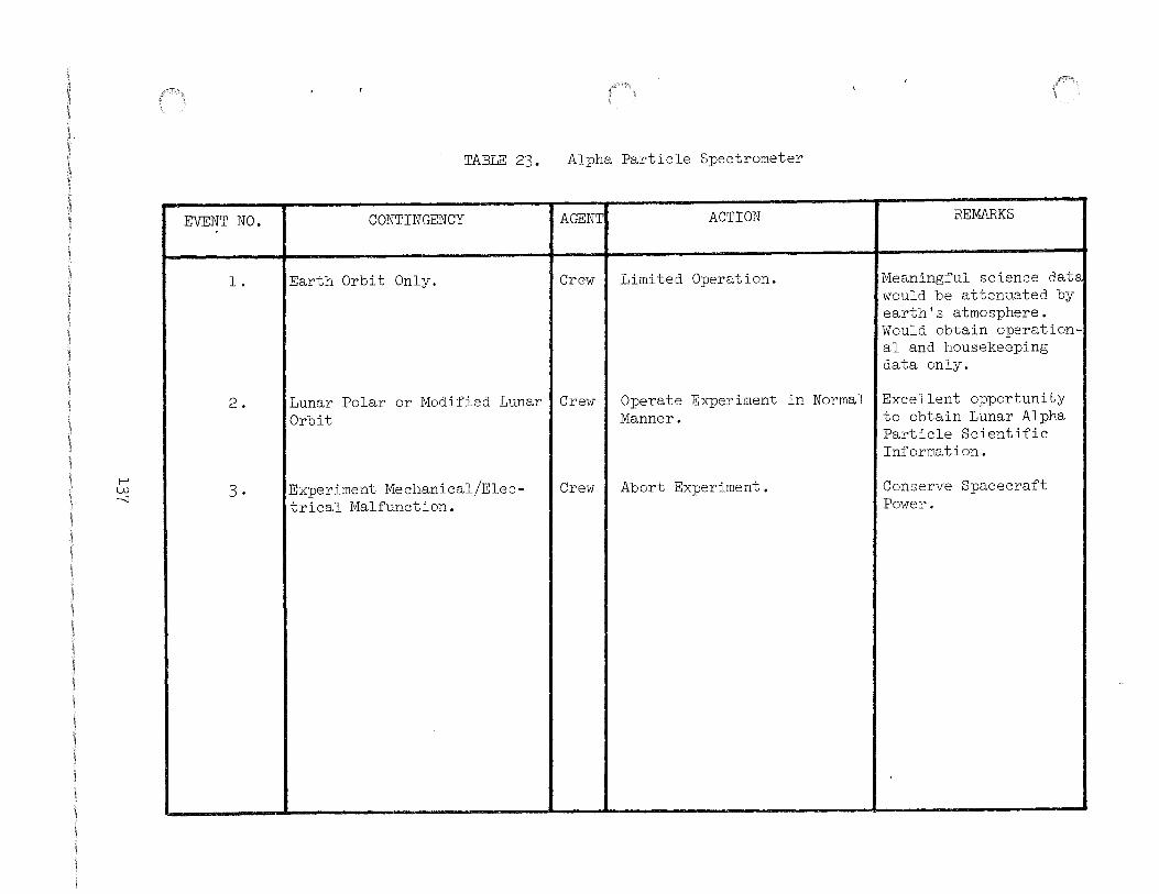
1-' w ......;]
EVENT NO.
l.
2 .
3 .
TABLE 23.
CONTINGENCY
Earth Orbit Only.
Lunar Polar or Modified Lunar Orbit
Experiment Mechanical/Elec-trical Malfunction.
Alpha Particle Spectrometer
AGENT ACTION REMARKS
Crew Limited Operation. Meaningful science data would be attenuated by earth's atmosphere. Would obtain operation-al and housekeeping data only.
Crew Operate Experiment in Normal Excellent opportunity Manner. to obtain Lunar Alpha
Particle Scientific Information.
Crew Abort Experiment. Conserve Spacecraft Power.
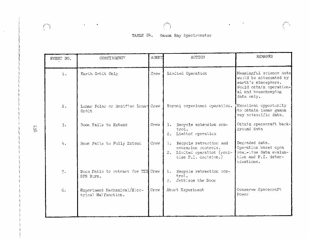
1-' w CD
EVENT NO.
l.
2.
3.
4.
5.
6.
TABLE 24. Gamma Ray Spectrometer
CONTINGENCY AGENTI ACTION REMARKS
Earth Orbit Only Crew I Limited Operation Meaningful science data would be attenuated by earth's atmosphere. Would obtain operational and housekeeping data only.
Lunar Polar or Modified Lunarl Crew Orbit
Boom Fails to Extend Crew
Boom Fails to Fully Extend Crew
Boom Fails to retract for TEIICrew SPS Burn.
Experiment Mechanical/Electrical Malfunction.
Crew
Normal experiment operation. rExcellent opportunity to obtain lunar gamma ray scientific data.
l. Recycle extension control.
2. Limited operation
l.
2.
Recycle retraction and extension controls. Limited operation (realtime P.I. decision.)
l. Recycle retraction control.
2. Jettison the Boom
Abort Experiment
Obtain spacecraft background data
Degraded data. Operation based upon real-time data evaluation and P.I. determinations.
Conserve Spacecraft Power

TABLE 25. X-Ray Fluorescence Spectrometer
EVENT NO. CONTINGENCY AGENT ACTION REMARKS
l. I Earth Orbit Only. fCrew I Limited Operation. fMeaningful scientific data would be attenua-ted by earth's atmos-phere. Would obtain operational and house-keeping data only.
2. I Lunar Polar or Modified I Crew Normal Experiment Operation. !Excellent opportunity Lunar Orbit. to obtain Lunar X-Ray
scientific data. I I I I I
1-' w \0 I 3. I Experiment Sensor Direct I Crew I Normal Experiment Operation. ~Degraded data. P.I.
Sunlight Exposure. determination based upon real-time data evaluation.
4. I Experiment mechanical/elec- Crew Abort Experiment Conserve Spacecraft trical malfunction. Power.

I-' + 0
EVENT NO.
l.
2·
3.
4.
5·
6.
TABLE 26. Mass Spectrometer
CONTINGENCY AGENTI ACTION REMARKS
Earth Orbit Only Crew I Limited Operation Obtain operational and housekeeping data only.
Lunar Polar or Modified LunariCrew Orbit
Boom Fails to Extend
Boom Fails to Extend
Boom Fails to retract for TEI SPS Burn.
Experiment Mechanical/Electrical Malfunction.
Crew
Crew
Crew
Crew
Normal experiment operation. IExcellent opportunity to obtain lunar scientific data.
l. Exercise extension control.
2. Limited operation.
l.
2.
Exercise retraction and extension controls. Limited operation (realtime P.I. decision).
l. Exercise retraction control.
2. Jettison the Boom.
Abort Experiment
Obtain spacecraft background data.
Degraded data. Operation based upon real-time data evaluation and P.I. determinations
Conserve Spacecraft Power

t-' _J::--1-"'
EVENT NO.
l.
2.
3-
4.
TABLE 27. Gegenschein ~rom Lunar Orbit
CONTINGENCY I AGENTI ACTION REMARKS
Not possible to schedule dur-~ MCC/ I Try during TEC. ing lunar orbit. Crew
updated pointing.
Film magazine jams or ~ails. Crew I Switch to other magazine us in@ dim light (~ast) ~ilm.
Attitude rates higher than allowed.
Crew I l. Control rates to low as possible.
2. Try 2 minute exposures.
I Not enough time to accomplish I Crew I Photo priority all photography.
l. 2 minute exposures
2. 2 minute exposures
3. 2 minute exposures
4. l minute exposures
5. l minute exposures
6. l minute exposures
May reduce number o~ exposures.
0~ Moulton Point
0~ Antisolar Point
0~ Midway Point I Of Moulton Point
0~ Antisolar Point
I 0~ Midway Point

ABBREVIATIONS
ALSEP
* CCGE CDR CLSRC CSM
DRT
EMU EVA
FTT
HFE HTC
LEC 1M LMP LRRR/LR3 LSM
MCC MESA
PCU PDR PSE
RTG
SEQ/Bay SESC SIDE SRC swc sws
TM
UHT
APPENDIX
ABBREVIATIONS AND ACRONYMS
DEFINITIONS
Apollo Lunar Surface Experiment Package
Cold Cathode Gauge Experiment Commander Contingency Lunar Sample Return Container Command Service Module
Dome Removal Tool
Extravehicular Mobility Unit Extravehicular Activity
Fuel Transfer Tool
Heat Flow Experiment Hand Tool Carrier
Lunar Equipment Conveyer Lunar Module Lunar Module Pilot Laser Ranging Retro-Reflector Lunar Surface Magnetometer
Mission Control Center Modularized Equipment Stowage Assembly
Power Control Unit Power Dissipation Resister Passive Seismic Experiment
Radioisotope Thermoelectric Generator
Scientific Equipment Bay Special Environmental Sample Container Suprathermal Ion Detector Experiment Sample Return Container Solar Wind Composition Solar Wind Spectrometer
Telemetry
Universal Handling Tool
* The abbreviations CCIG and CCGE are often used interchangeable, however, CCIG is the nomenclature assigned by NASA Headquarters to the instrument described herein.
A-l


Addressees: CAjD. K. Slayton CBjJ. P. Allen CGjJ. W. Bilodeau CG3/R. G. Zedekar (5) CG3/J. McKee (3) CG5/T. W. Holloway (3) EE3/L. Leopold EHjD. G. Wiseman (5) FC9/J. E. Saultz (5) JM2jE. Hill (3) PD4/J. R. Sevier PD7/J. Peacock PG/R. New lander TA/ A. J. Calio TAjJ. A. Lovell TA/ G. Simmons TD4jR. A. Moke (10) TD5/R. R. Baldwin TD5/F. J. Herbert TD5/J. R. Bates TNjP. W. Gast (3) TF/D. E. Evans TDXjR. Miley ( 5) NASA Hqs, W. T. O'Bryant, MAL (3) KSC, C. M. Vaughn, PSK
MSC-04105

Addressees:
Dr. Gary V. Latham Lamont-Doherty Geological Observatory Columbia University Palisades, New York 10964
Dr. Marcus E. Langseth Lamont-Doherty Geological Observatory Columbia University Palisades, New York 10964
Dr. Francis S. Johnson University of Texas at Dallas P.O. Box 30365 Dallas, Texas 75230
Dr. John W. Freeman Department of Space Science Rice University Houston, Texas 77001
Dr. Conway W. Snyder Jet Propulsion Laboratory 4800 Oak Grove Drive Pasadena, California 91103
Mr. James R. Bates Mail Code: TD5 Science Requirements and
Operations Branch NASA-Manned Spacecraft Center Houston, Texas 77058
Dr. J. Faller Scott Laboratory Wesleyan University Middletown, Connecticut o6457
Dr. Palmer Dyal, Code N204-4 Space Science Division Electrodynamics Branch Ames Research Center Moffett Field, California 94034
Dr. Gordon Swann Center of Astrogeology U.S. Geological Survey 601 E. Cedar Avenue Flagstaff, Arizona 86001
MSC-04105
Dr. Robert 0. Pepin School of Physics and Astromony University of Minnesota Minneapolis, Minnesota 55455
Dr. James K. Mitchell Department of Civil Engineering 440 Davis Hall University of California at
Berkeley Berkeley, California 94726
Dr. Johannes Geiss University of Berne Physikalisches Institut Sidlerstrasse 5 Berne, Switzerland
Mr. Lawrence Dunkelman Planetary Optics Section Mail Code: 673 Goddard Space Flight Center Greenbelt, Maryland 20771
Mr. H. T. Howard Stanford Electronic Laboratories Stanford University Stanford, California 94305
Mr. F. J. Doyle U.S. Geological Survey Topographic Division 1340 Old Chain Bridge Road McLean, Virginia 22101
Dr. William M. Kaula Institute of Geophysics and
Planetary Physics University of California at
Los Angeles Los Angeles, California 90024
Dr. James R. Arnold Chemistry Department University of California at
San Diego La Jolla, California 92037

Addressees:
Dr. Isidore Adler Theoretical Studies Branch - Code 641 NASA-Goddard Space Flight Center Greenbelt, Maryland 20771
Dr. Paul Gorenstein American Science and Engineering, Inc. ll Carleton Street Cambridge, Massachusetts 02142
Dr. John H. Hoffman Atmospheric and Space Sciences University of Texas at Dallas P.O. Box 30365 Dallas, Texas 75230
Mr. William L. Sjogren Mail Code: 156-251 Jet Propulsion Laboratory 4800 Oak Grove Drive Pasadena, California 91103
Dr. Kinsey A. Anderson Space Science Laboratory University of California at Berkeley Berkeley, California 94726
Dr. Paul J. Coleman, Jr. Department of Planetary and Space Science University of California at Los Angeles Los Angeles, California 90024
Mr. D. S. Crouch Martin Marietta Corporation Denver Division Mail Code 1640 P.O. Box 179 Denver, Colorado
Mr. J. Head Be llcomm, Inc.
80201
955 L'Enfant Plaza North, S.W. Washington, D.C. 20546
MSC-04105