science-technology co., ltd max drive system · science-technology co., ltd no. 9 heshun rd ... the...
TRANSCRIPT

dealer Manual
MAX Drive System
EN
Suzhou Bafang Electric Motor
Science-Technology Co., Ltd
No. 9 Heshun Rd
Suzhou Industrial Park
215122, Suzhou China
www.szbaf.com

1 DEALER MAnuAL Max Drive SySteM

2 DEALER MAnuAL Max Drive SySteM
ContEnt
Important notice 4
For your Safety 5
note 6
1 Drive Unit (MM G33.350) 7
1.1 Advantages 7
1.2 Scope of Application 7
1.3 Product naming Protocol 7
1.4 Main technical Parameters 8
1.5 Drive unit Structure and Dimensions 9
2 System Installation 10
2.1 List of tools to be used 10
2.2 Component names 11
2.3 Display Installation (DP C01.RS232.7) 12
2.4 Auxiliary Keypad Installation 13
2.5 Battery Rail Installation 15
2.6 External Speed Sensor Installation SR SD02.01 15
2.7 Drive unit Installation 18
3 System Cabling 25
3.1 Connection of the Battery Cable to the Drive unit 25
3.2 Connection of the Speed Sensor to the Drive unit 25
3.3 Connection of the EB-BuS to the Drive unit 26
3.4 Connection of the Headlight Cable to the Drive unit 26
3.5 Connection of the Headlight to the Drive unit 27
4 Chain guard Installation 28
4.1 Installation of the Front Chainwheel 28
4.2 Chain Guard Installation (optional) 30
4.3 Crank Installation 37
5 Battery (BT C01.690) 39
5.1 using the Battery Properly 40
5.2 Charging the Battery 40
5.3 Battery Capacity Display 41
5.4 Battery Health Indication 41
5.5 Battery Installation 42
6 Display (DP C01.RS232.7) 43
6.1 Specifications and Parameters of the Display 43
6.2 Appearance and Dimensions 43
6.3 Function overview and Key Definitions 44
6.4 normal operation 46
6.5 Parameter Setting 48
6.6 Error Code Definitions 55
7 List of Materials 56
7.1 Display unit - DP C01.RS232.7 56
7.2 Drive unit - MM G33.350 56
7.3 Cables 58
8 Service and Warranty Policy 59
notes 60
Content

3 DEALER MAnuAL Max Drive SySteM

4 DEALER MAnuAL Max Drive SySteM
IMPoRtAnt notICE
iMportant notiCe
• the Dealer Manual is to be used by professional e-bike mechanics. Dealers who have not received training on electric bicycle assembly shall not attempt to assemble parts and components by following the Dealer Manual.
• If in doubt about any part of the manual, do not attempt to install the product. Please consult the local sales office or an electric bicycle dealer for help.
• Make sure you read all of the installation manuals delivered with the product.
• Do not disassemble or modify the product unless specified by the Dealer Manual.
• the Dealer Manual is available on our website (www.szbaf.com).
• the dealer shall observe the laws and regulations of the region, the state and the country where the product is sold.
Make sure you have read this Dealer Manual carefully in order to use the product properly.

5 DEALER MAnuAL Max Drive SySteM
For your SaFety
When installing this product, be sure to follow the instructions given in the manual!
It is recommended that you use only genuine BAFAnG parts at all times. Serious injury may result if loose or faulty bolts and nuts suddenly come off.
If the product is improperly adjusted, accidents and serious injury can occur.
• When performing maintenance operations (for example parts replacement), be sure to wear goggles or eye protection.
• Please refer to the website www.szbaf.com or contact the dealer for information on the product not covered by this manual.
• Keep this Dealer Manual in a safe place for later reference.
Inform the purchaser about the following issues:
• Giving too much of your attention to the e-bike display while riding can lead to an accident.
• It is important to check that the wheels are properly fitted to the bicycle before commencing riding. If the wheels are not securely attached fixed serious injury may result.
• When riding a pedal-assisted electric bicycle, you should be fully familiar with the starting-off characteristics of the e-bike before riding it. If the e-bike starts off suddenly, accidents may result.
• It is important to turn on the lights when riding in the evening and at night.
Instructions on e-bike installation and maintenance
• When cabling the product or installing the parts onto the e-bike, be sure to disconnect the battery. not doing so may result in electric shock.
• When installing this product, be sure to follow the instructions given in the manual. If bolts and nuts are not tightened correctly or if the product is damaged, the e-bike may suddenly fall over and serious injury may result.
• the frequency of maintenance will vary depending on the usage of the e-bike. the chain should be cleaned periodically using an appropriate chain cleaner. Do not use alkaline or acidic cleaning agents to remove rust under any circumstances. If such cleaning agents are used, they may damage the chain and serious injury may result.

6
DEALER MAnuAL Max Drive SySteM
HAnDLInG InFoRMAtIon
note
Important information for the purchaser:
• Please follow instructions given in the manual for your riding safety.
• Examine the battery charger regularly for damage, especially the cable, plug and housing. If the battery charger is damaged, it must not be used until it has been repaired.
• Please follow the guidance given by the safety supervisor or the instructions indicated in the manual when using the product. this product is not intended for use by persons (including children) with reduced physical, sensory or mental capabilities or persons lacking experience and knowledge in using the product.
• Do not allow children to play near the product.
• Please consult the nearest dealer for any errors or problems.
• Do not modify the system. Doing so may lead to malfunction of the system.
• For information on product installation and adjustment, please consult your dealer.
• the product is designed to be fully waterproof to withstand wet weather riding conditions. Howe-ver, do not deliberately immerse it in water.
• Do not clean the bicycle with a high-pressure water spray. If water gets into any of the compo-nents, operation problems or rusting may result.
• When transporting the product on a car in wet weather, remove the battery and put it in a safe place to stop it from getting wet due to the rain.
• Handle the product carefully and avoid subjecting it to any strong shocks.
• Some important information given in this manual may also be found on the product labels.
• When buying a spare key for the battery, be sure to provide the number on the battery key. Please write down the number and keep it in a safe place.
• use a wrung-out damp cloth to clean the battery and the plastic housing.
• For any questions regarding the maintenance and use of the product, please contact your dealer.
• normal wear and tear due to normal use and aging is not within our scope of quality guarantee.
• Please contact the seller for software updates. the newest information on software is available on the official Bafang website: www.szbaf.com.

7 DEALER MAnuAL Max Drive SySteM
1 Drive unit (MM G33.350)
1.1 advantages
• use of torque measurement, pedal-assist speed measurement and wheel-speed measurement; the system has a dual feedback protection of the speed signals to ensure safety and reliability of the system
• High starting torque, maximum torque of more than 80 nm, especially suitable for hill climbing
• High efficiency, low power consumption, longer range
• Low noise, smooth operation
1.2 Scope of application
the drive unit works properly in the following environ-mental conditions:
• Ambient temperature: -20 to + 55°C ;
• Relative humidity: 15 – 95 % RH;
the function of the product is impaired by the presence of any major caustic gas, any medium that affects the product’s electrical insulation properties or any high-intensity magnetic field.
1.3 product naming protocol
there is a badge on the housing, showing information as follows:
MM G33.350 14010001 36 V 250 W
A b C D
A MM G33.350 name of the drive unit
b 1401 Date of production, January 2014 in this example; 0001 Production serial number, ran-ging from 0000 to 9999; 0001 is the production serial number of the first motor
C 36V Rated voltage suitable for 36V drive systems
D 250 W Rated motor power

8
DRIVE unIt (MM G33.350)
DEALER MAnuAL Max Drive SySteM
1.4 Main technical parameters
Rated voltage (DCV) 36 / 43
Rated power (W) 250 350 / 250 350
Rated efficiency (%) ≥ 80%
Rated rotating speed (rpm) 100 ± 5
Maximum torque (nm) ≥ 80
Chain wheel 36t (recommended), 38t (optional), 42t (optional)
optional chain guard full chain guard / P-shaped chain guard
Weight (Kg) 3.9
Sensors pedal assist speed sensor, pedal assist torque sensor and bicycle wheel speed sensor and temperature sensor
noise (dB) < 55
Working environment -20°C~55°C
Dust-proof/ water-proof grade IP 66
Certification CE RoHS/ En14766/ En14764/ REACH
Functions Light function: DC 500mA/6V headlight & rearlight
optional functions: Bluetooth module, gear sensor, reprogramming function
9 DEALER MAnuAL Max Drive SySteM
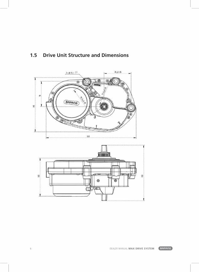
1.5 Drive unit Structure and Dimensions

10
SyStEM InStALLAtIon
DEALER MAnuAL Max Drive SySteM
2 SySteM inStallation
2.1 list of tools to be used
Components Use of the Tools Tools
Display to tighten M3 & M4 screws2,5mm
Internal hex wrench
Drive unit
to fix the chain wheel retaining ring
Special tool
to remove the chain wheel retaining ring
Plier for the retaining ring
to tighten M4 screws on the chain guard
Cross screwdriver
to fasten M6 bolts and nuts onto the frame adapter and the drive unit
Internal hexagonal wrench
to fasten M8 screws on the crank mounting
Internal hexagonal wrench
Speed Sensor
to install the iron magnetStraight slot screwdriver
to tighten M5 screws of the speed sensor
Phillips screwdriver
Batteryto fasten the battery plate onto the carrier using M5 screws
Internal hex wrench
the tool used to install the retaining ring onto the hub
tool code (GZ-MM G31-5025)

11 DEALER MAnuAL Max Drive SySteM
2.2 Component names
b ACD
e f
b ACD
A Drive unit
b Front chain wheel
C External speed sensor
D Battery
e Auxiliary keypad
f Display

12
SyStEM InStALLAtIon
DEALER MAnuAL Max Drive SySteM
2.3 Display installation (Dp C01.rS232.7)
A Rubber clamping ring (whose inner diameter is Ø 22.2 or Ø 25.4) 2316020400007 2316020400008 Left and right display clamps for the Ø 22.2 handlebar: Left clamp -2316020400017 Right clamp -2316020400018 Left and right display clamps for the Ø 25.4 handlebar: Left clamp -2316020400007 Right clamp -2316020400008
one or two rubber clamping rings may be needed depending on the diameter of the handlebar (the applicable handlebar specifications are Ø 22.2, Ø 25.4 and Ø 31.8). open the left or right display clamp, and insert one or two clamping rings into the right position of the display clamp as shown in the picture above.
Insert the clamping ring(s) to each of the two display clamps and mount them onto the handlebar. use an internal hex wrench to fasten the left and right clamps onto the handlebar.
b display clamp
C hex socket head cap screws M4×8

13 DEALER MAnuAL Max Drive SySteM
Adjust the angle of the display so that you can easily see the display screen when riding. After the angle has been adjusted, tighten the screws to the specified torque.
tightening torque: 1 nm
2.4 auxiliary Keypad installation
A keypad clamp
open the auxiliary keypad and assemble it onto a position that is easy for operation. Adjust the angle of the auxiliary keypad to ensure that the keypad is easy to see seen during riding.
(Applicable to the handlebar whose external diameter is Ø 22.2mm)

14
SyStEM InStALLAtIon
DEALER MAnuAL Max Drive SySteM
2,5mm
b hex socket head cap screw M3×8
Fix the keypad onto the handlebar with a screw. then tighten the fixing screw with an internal hex wrench.
tightening torque: 1 nm
H female connector at the display
h male connector at the EB-BuS
Match the female connector at the display with the male connector at the EB-BuS as shown in the picture above.

15 DEALER MAnuAL Max Drive SySteM
2.5 Battery rail installation
A hex socket head cap screw (M5)
Align the mounting holes of the carrier with the mounting holes of the battery rail. Fasten the battery rail onto the battery carrier with hex socket head screws (M5).
tightening torque: 2 nm
2.6 external Speed Sensor installation Sr SD02.01
A external speed sensor
b magnet unit
C spoke
D chain stay
Before installing the speed sensor, please make sure the gap between the speed sensor and the magnetic unit is between 5 and 25 mm.

16
SyStEM InStALLAtIon
DEALER MAnuAL Max Drive SySteM
A Dust cap 2301030000003
b mounting bolt M5×12
C external speed sensor
D sensor bracket (chain stay boss)
If the gap is within the specified range, use the mounting bolt to fix the speed sensor.
If the gap is more than 25 mm, please put spacers between the sensor and the chain stay boss to reduce this gap.
tightening torque: 1.5 – 2 nm
Arrange the speed sensor and the magnet unit as shown in the picture above. When installing the magnet unit, make sure its center is aligned with the center of the speed sensor’s induction zone.

17 DEALER MAnuAL Max Drive SySteM
A external speed sensor
b magnet unit PS01010702/ 2308040000001
C spoke
Arrange the speed sensor and the magnet unit as shown by the picture above. Mount the magnet unit onto the spoke.
D Mounting nut of the magnet PS01010701/ 2327000000003
tighten up the mounting nut with a straight slot screwdriver. tightening torque: 1.5 – 2 nm

18
SyStEM InStALLAtIon
DEALER MAnuAL Max Drive SySteM
2.7 Drive unit installation
A battery cable
b taillight cable
C external speed sensor cable
D headlight cable
e EB-BuS
Cables should be arranged in advance according to the e-bike type and the cabling system before installing the drive unit.
A mounting holes
b drive unit MM G33.350
Align the three mounting holes of the drive unit with the mounting holes in the bike frame.
Pay attention to the outgoing directions of the cables. Please note that the cables should not be squeezed by the drive unit.
19 DEALER MAnuAL Max Drive SySteM
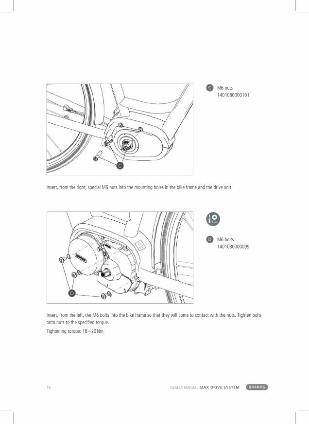
C M6 nuts 1401080000101
Insert, from the right, special M6 nuts into the mounting holes in the bike frame and the drive unit.
D M6 bolts 1401080000099
Insert, from the left, the M6 bolts into the bike frame so that they will come to contact with the nuts. tighten bolts onto nuts to the specified torque.
tightening torque: 18 – 20 nm

20
SyStEM InStALLAtIon
DEALER MAnuAL Max Drive SySteM
A upper cover of the connector box
b connector box body
open the connector box and get ready to link female connectors with male connectors.
Push the lower part of each of the male buckles on the connector box body (in the direction as show by the arrows in the picture above) to release the female buckles on the upper cover. Push the upper cover in the direction of moving towards Buckle 3 to fully open the upper cover.

21 DEALER MAnuAL Max Drive SySteM
C cabling layout 2307070000001
D cable clips 1401300000001
open the connector box, link all cables to the drive unit and fix all connectors in the connector box according to the cabling diagram printed on the upper cover of the connector box (see C in the picture above).
After matching all male connectors with female connectors, cover the connector box with the upper cover and thread the cables through cable clips (D in the picture above) following the principle of "thin cables on top and thick cables below" to ensure that the cables are neatly arranged.

22
SyStEM InStALLAtIon
DEALER MAnuAL Max Drive SySteM
the picture above shows how the drive unit looks after cabling.
Please note that all cables must thread through the cable clips after going out of the connector box.
A frame adapter
b drive unit cover 1333000000001
Push the buckle on the drive unit cover into the slot on the frame adapter.

23 DEALER MAnuAL Max Drive SySteM
Figure 1
Figure 2
C screw holes on the drive unit’s cover
D end cover on the right
e cable gatherer 1401150100005
f cross head screw assem-bly M3×8 1401020000127
Make sure that the cover is securely clicked into place. Screw the cover tightly onto the drive unit (see Figure 1). If brake cables and gear cables are to be routed under the drive unit, bind e together with a cable gatherer, see Figure 2).
tightening torque: 1 nm

24
SyStEM InStALLAtIon
DEALER MAnuAL Max Drive SySteM
Figure 3
Figure 4
Figures above show how the drive unit looks like when the drive unit cover has been affixed.
Brake cables and gear cables can either be arranged in the channel at the bottom of the drive unit (see Figure 3 where cable gatherers are provided) or within the inner space of the frame adapter (see Figure 4 where no cable gatherers are provided).

25 DEALER MAnuAL Max Drive SySteM
3 SySteM CaBlinG
3.1 Connection of the Battery Cable to the Drive unit
A female connector for the communication cables at the battery
a male connector for the communication cables at the drive unit
b female connector for the positive cable at the battery
b male connector for the negative cable at the drive unit
C male connector for the negative cable at the battery
c female connector for the negative cable at the drive unit
the power bus, which is made up of a positive battery cable, a negative battery cable and battery communication cables, is connected to the battery cables at the drive unit.
3.2 Connection of the Speed Sensor to the Drive unit
e male connector at the speed sensor
e female connector at the drive unit for connection to the speed sensor
Link the male connector at the external speed-detecting sensor to the female connector for the external speed- detecting sensor cable at the drive unit.

26
SyStEM CABLInG
DEALER MAnuAL Max Drive SySteM
3.3 Connection of the eB-BuS to the Drive unit
D male connector at the EB-BuS 2105020000099
d female connector at the drive unit for connection to the EB-BuS
Link the EB-BuS cable to the EB-BuS connector at the drive unit.
3.4 Connection of the Headlight Cable to the Drive unit
f female connector at the headlight cable
f male connector for the headlight at the drive unit
Link the headlight cable to the connector for the headlight at the drive unit.

27 DEALER MAnuAL Max Drive SySteM
3.5 Connection of the Headlight to the Drive unit
g female connector at the headlight cable
g male connector for the headlight at the drive unit
Link the headlight cable to the connector at the drive unit.

28
CHAIn GuARD InStALLAtIon
DEALER MAnuAL Max Drive SySteM
4 CHain GuarD inStallation
4.1 installation of the Front Chainwheel (without a chain guard)
A chain wheel
b retaining ring
1401010000026
Put the front chain wheel onto the spline shaft of the drive unit.
b retaining ring
C a special tool used to install the retaining ring onto the hub tool code: GZ-MM G31-5025
use a special tool to fix the retaining ring onto the spline shaft.
A used retaining ring must be replaced.

29 DEALER MAnuAL Max Drive SySteM
integratable chain wheel guard
1325020000002
Chain Line: 48 mm, Preferably 36 / 38 t
Applicable to a city bike, which is equipped with an internal gearshift system (not a full chain guard).
Chain Line: 48 mm, Preferably 36 / 38 t
Applicable to a city or mountain bike with an external gearshift system.
integratable chain wheel guard
1325020000002

30
CHAIn GuARD InStALLAtIon
DEALER MAnuAL Max Drive SySteM
4.2 Chain Guard installation (optional)
Installation of a full chain guard
A chain guard binder plate and screws are necessary for installing a full chain guard.

31 DEALER MAnuAL Max Drive SySteM
A full chain guard
b binder plate 1401150100004
C screws M4 1401020000111
open the full chain guard and adjust it by following the instruction book. Make sure the outer wall of the full chain guard is aligned with the boss on the outer side of the drive unit. then press the inner wall of the full chain guard onto the binder plate and fasten them with screws.
tightening torque: 2 nm
32
CHAIn GuARD InStALLAtIon
DEALER MAnuAL Max Drive SySteM
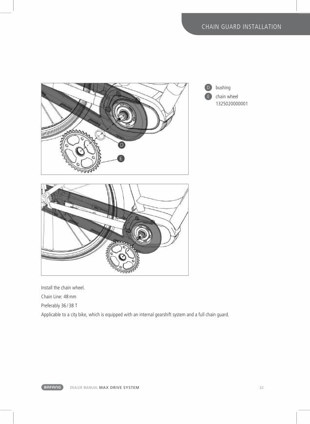
D bushing
e chain wheel 1325020000001
Install the chain wheel.
Chain Line: 48 mm
Preferably 36 / 38 t
Applicable to a city bike, which is equipped with an internal gearshift system and a full chain guard.

33 DEALER MAnuAL Max Drive SySteM
Refer to the chain guard instruction book and install the chain guard after the chain wheel has been installed.
not all full chain guards are compatible with the MAX drive unit.

34
CHAIn GuARD InStALLAtIon
DEALER MAnuAL Max Drive SySteM
Installation of the p-shaped (semi) chain guard
A p-shaped chain guard bracket 1401220200003
b screws M4 1401020000111
Position the p-shaped chain guard bracket and fasten it onto the drive unit with screws.
tightening torque: 2 nm

35 DEALER MAnuAL Max Drive SySteM
C CL-45 mm chain wheel module 132502000000
Install the chain wheel in the appropriate position. Chain Line: 45 mm Preferably 36 / 38 t Applicable to a city bike with an internal gearshift system and a semi chain guard.
Fix the chain wheel onto the drive unit.
36
CHAIn GuARD InStALLAtIon
DEALER MAnuAL Max Drive SySteM
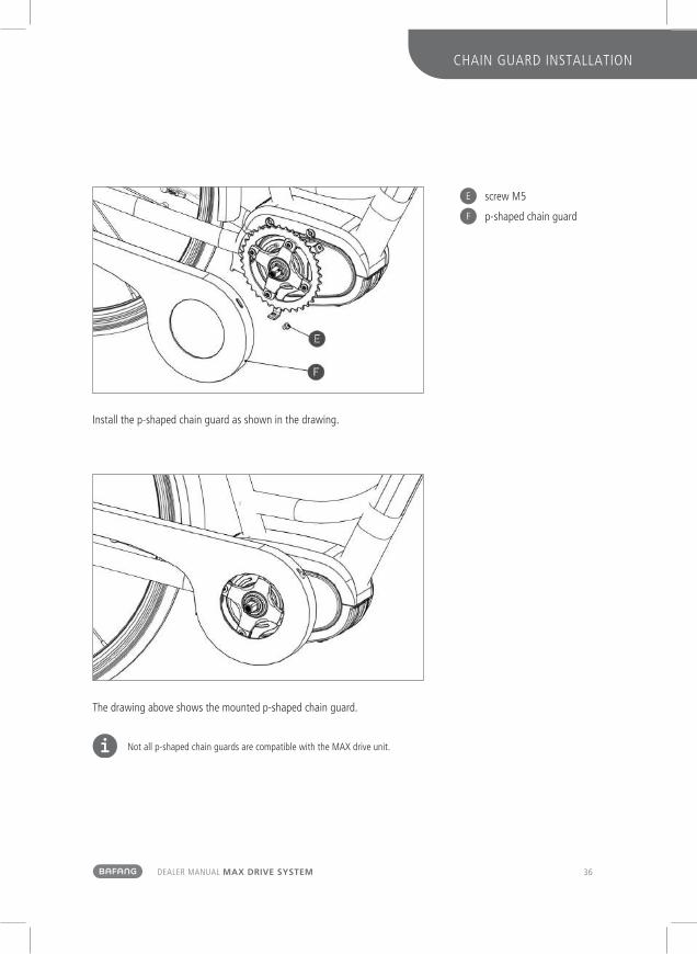
e screw M5
f p-shaped chain guard
Install the p-shaped chain guard as shown in the drawing.
the drawing above shows the mounted p-shaped chain guard.
not all p-shaped chain guards are compatible with the MAX drive unit.

37 DEALER MAnuAL Max Drive SySteM
4.3 Crank installation
Installation of the crank with a chain guard
A right straight crank with a cap 1327040000001 left straight crank 1327020000001
b screws M8 for mounting the crank 1401020000109
Different right cranks are used depending on the chain guard.
Fasten the right crank onto the bottom bracket on the right with a screw M8. Install the left crank in the same way.
torque: 35 – 40 nm

38
CHAIn GuARD InStALLAtIon
DEALER MAnuAL Max Drive SySteM
Installation of the crank without a chain guard
A right straight crank 1327010000001
left straight crank 1327020000001
b screws M8 for mounting the crank 1401020000109
Fasten the right crank onto the bottom bracket on the right with a screw M8. Install the left crank in the same way.
torque: 35 – 40 nm

39 DEALER MAnuAL Max Drive SySteM
5 Battery (Bt C01.690)
precautions
• If any liquid leaking from the battery gets into your eyes, rinse immediately with clean water (e.g. tap water). Seek medical advice immediately; otherwise the battery liquid may damage your eyes.
• Do not recharge the battery in places with high humidity or outdoors. Doing so may result in electric shock.
• Do not insert the plug while it is wet. Plug and socket need to be dry, otherwise electric shocks may result.
• If the battery does not become fully charged after 6 hours, unplug the battery from the outlet imme-diately and stop charging. not doing so may cause overheating, rupture, or ignition of the battery.
• Do not use the battery if it has any noticeable damage. Doing so may cause rupture, overheating or malfunction.
• the battery may only be used in the temperature ranges states below. Do not use the battery in temperatures outside these ranges. If the battery is used or stored in temperatures outside these ranges, fire, injury or malfunction may occur.
• 1. temperature for discharging: –10°C to 50°C
• 2. temperature for charging: 0°C to 40°C
Danger
• Do not deform, modify or disassemble the battery. Do not apply solder directly to the battery. Doing so may cause leakage, overheating, rupture or ignition of the battery.
• Do not leave the battery near sources of heat (e.g. heaters). Do not heat the battery or throw it into a fire. Doing so may cause rupture or ignition of the battery.
• Do not subject the battery to strong shocks or th-row it. If this is not observed, overheating, rupture or ignition of the battery may occur.
• Do not immerse the battery into fresh water or seawater, and do not allow the battery terminals to get wet. Doing so may cause overheating, rupture or ignition of the battery.
• only use the specified charger. not doing so may cause overheating, bursting, or ignition of the bat-tery. observe the components during the specified charging conditions when charging the battery.
• Do not short-circuit the discharge port with metal, or else it may cause overheating, rupture or ignition of the battery.
• Do not leave the battery in a place exposed to direct sunlight, inside a vehicle on a hot day or in other hot places. Doing so may result in battery leakage.
• If any leaked fluid gets on your skin or clothes, wash it off immediately with clean water. the leaked fluid may damage your skin.
• Store the battery in a safe place out of the reach of children and pets.

40
BAttERy (Bt C01.690)
DEALER MAnuAL Max Drive SySteM
5.1 using the Battery properly
The battery can be charged at any time no matter how much power is left. However, in the following cases, the battery needs to be fully charged. Make sure you use the specified charger to charge the battery.
• the battery is usually not fully charged for the convenience of transport. Make sure the battery is fully charged before using the battery.
• If it is not intended to use the battery for a long time, make sure the e-bike battery is charged before storage and that is charged at least once every twelve months thereafter. Do not leave the battery completely discharged.
• once you have begun to use the battery, please have it charged at least once every two weeks.
If the battery is completely discharged, charge it as soon as possible. If you do not charge the battery, it will be damaged.
5.2 Charging the Battery
• When using the battery for the first time, check that the battery has not run low in transport or storage.
• If it not intended to use the battery for a long time, charge the battery regularly to avoid excessi-ve battery discharge.
• Please charge the battery as soon as possible before it runs out; over-discharge can cause permanent damage to the battery.
• no matter how much power is left, the battery can be charged at any time. However, the speci-fied charger must be used to avoid overcharge of the battery.
Display Light
Battery Level Display Switch

41 DEALER MAnuAL Max Drive SySteM
5.3 Battery Capacity Display
Press the battery level display switch lightly. the lights indicating the remaining battery capacity will appear:
Battery Capacity Display
Remaining Battery Capacity
< 10 %
11~30 %
31~50 %
51~70 %
71~90 %
91~100 %
Light on
Light off
5.4 Battery Health indication
Press the battery level display switch for one second. the battery health will be indicated as follows:
Light on
Light off
Battery Health Indication
Battery Health Condition
< 40 %
41~50 %
51~60 %
61~70 %
71~80 %
81~100 %

42
BAttERy (Bt C01.690)
DEALER MAnuAL Max Drive SySteM
5.5 Battery installation
A battery pack lock
b battery
Insert the battery pack from the tail of the carrier onto the rail. Push it to the front until you hear it snap into place in the battery pack lock.
Please make sure the battery pack is locked to prevent the battery from becoming detached while riding.
43 DEALER MAnuAL Max Drive SySteM
6 DiSplay (Dp C01.rS232.7)
6.1 Specifications and parameters of the Display
• 36 V / 48 V Power Supply;
• Rated Current: 10 mA
• Maximum operating Current: 30 mA
• Power-off Leakage Current: < 1uA
• operating Current Supplied to the Controller: 50 mA
• operation temperature: -18 ~ 60 %
• Storage temperature: -30 ~ 70 %
• Waterproof Grade: IP65
• Storage Humidity: 30 % – 70 %
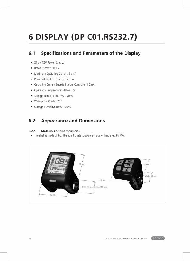
6.2 appearance and Dimensions
6.2.1 Materials and Dimensions• the shell is made of PC. the liquid crystal display is made of hardened PMMA.
44
DISPLAy (DP C01.RS232.7)
DEALER MAnuAL Max Drive SySteM
6.3 Function overview and Key Definitions
6.3.1 Function overview• use of a two-way serial communication protocol,
simple operation of the display via the external 5-key keypad.
• Speed display: displaying the real-time speed as SPEED, the maximum speed as MAXS and the average speed as AVG.
• km or mile: the user can choose between km and mile.
• Intelligent battery level indication: With an optimization algorithm, a stable display of the battery level is ensured, and the problem of fluc-tuant battery level indication common with other displays is avoided.
• Automatic light-sensitive lights: the headlight, taillight and display light will be automatically turned on/ off depending on lighting conditions.
• 5 levels off display backlighting: Different levels
• 5-Level-Support: setting power Levels 1 to 5
• trip distance indication: the maximum distance displayed is 99999. Single-trip distances tRIP or the total distance totAL can be displayed.
• Display of error messages
• Walk assistance
• Settings: Various parameters, e.g. mode, wheel diameter, speed limit etc., can be set on the com-puter via a communication cable. See the setting
• Maintenance warning (this function can be deac-tived): Maintenance warning information is dis-played based on battery charge cycles and riding distance. the display automatically estimates the battery life and gives warnings when the number of charge cycles exceeds the set value. A warning will also be displayed when the accumulated total riding distance exceeds the set value.
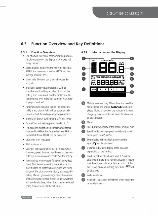
6.3.2 information on the Display
A Maintenance warning: When there is a need for maintenance the symbol will be dis-played (riding distance or the number of battery charge cycles exceed the set value, function can be deactivated)
b Menu
C Speed display: display of the speed, km/h or mph
D Speed mode: average speed (AVG km/h), maxi-mum speed (MAXS km/h)
e Error display: When a fault is detected the symbol will be displayed.
f Distance indication: display of the distance depending on the setting.
g Level indication: the chosen level 1–5 will be displayed; if there is no numeric display, it means that there is no assistance (by the motor). If the rider is walking and pushing the e-bike, will be displayed.
H Walk assistance
I Headlight indication: only shows when headlight or backlight are on
45 DEALER MAnuAL Max Drive SySteM
J Distance mode: display of the single-trip distance tRIP and the total distance totAL
K Battery level: 10-segment battery indication; the voltage that each segment represents can be customized
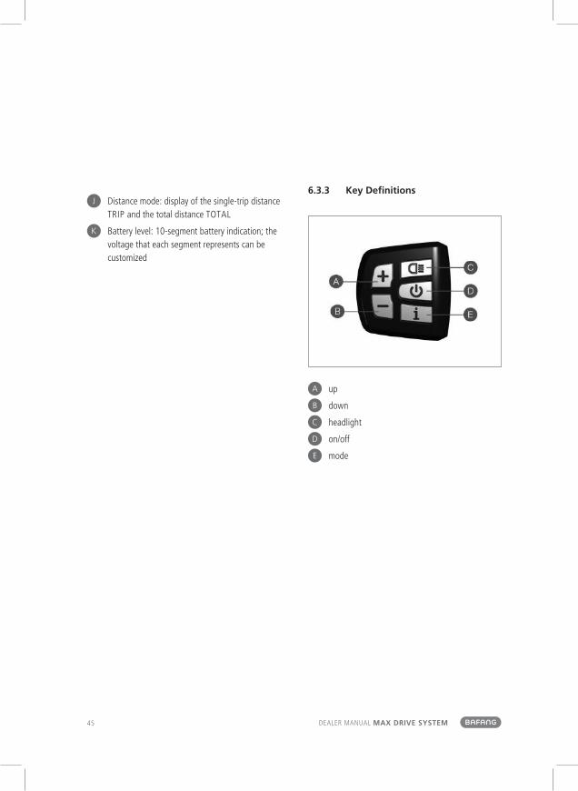
6.3.3 Key Definitions
A up
b down
C headlight
D on/off
e mode

46
DISPLAy (DP C01.RS232.7)
DEALER MAnuAL Max Drive SySteM
6.4 normal operation
6.4.1 on/off Switchturn on the device. Press and hold for 2 seconds to power on the display. Press and hold again for 2 seconds to power off the display. If the bike is not used, after 5 minutes (time can be set) the display will be automatically turned off.
6.4.2 assist Mode SelectionIn the manual gearshift mode, press the or to choose the desired level of support by the motor. the lowest level is Level 1, the highest Level 5. When the display is on, the default mode is Level 1. When there is no numeric mode display, there is no power assistance.
Selecting the level for motor assistance
6.4.3 Switch between Distance Mode and Speed Mode
Briefly press to switch between distance and speed. Single-trip distance (tRIP km) ➞ total distance (totAL km) ➞ maximum speed (MAXS km/h) ➞ average riding speed (AVG km/h) are displayed in successive order.
Switching between displays

47 DEALER MAnuAL Max Drive SySteM
6.4.4 Headlight/ Display Backlight Switch
Press for 2 seconds. the backlight of the display as well as the headlight and taillight will be turned on. Press again for 2 seconds to power off the display backlight/headlight/taillight. (If the display is turned on in a dark environment, the display backlight/headlight/taillight will be turned on automatically. If the display backlight/headlight/taillight are turned off manually, they also need to be turned on manually afterwards).
Display backlight, headlight and taillight
There are 5 levels of backlight brightness that can be
selected by the user.
6.4.5 Walk assistancePress for 2 seconds. the e-bike enters the walk assistance mode, and the symbol WALK is displayed. once the key is released, the e-bike will exit the walk assistance mode.
Switch between power assistance and walk assistance mode

48
DISPLAy (DP C01.RS232.7)
DEALER MAnuAL Max Drive SySteM
6.4.6 Battery Status indicationWhen the battery status is normal, a certain number of the battery LCD segments as well as the border light up according to the actual quantity of charge. If all of the 10 segments will black out with the border blinking, the battery needs to be charged immediately.
Battery status indication
Number of Segments
Charge in Percentage
Number of Segments
Charge in Percentage
Number of Segments
Charge in Percentage
10 ≥ 90 % 6 50 % ≤ C < 60 % 2 15 % ≤ C < 25 %
9 80 % ≤ C < 90 % 5 45 % ≤ C < 50 % 1 5 % ≤ C < 15 %
8 70 % ≤ C < 80 % 4 35 % ≤ C < 45 % border blinking C < 5 %
7 60 % ≤ C < 70 % 3 25 % ≤ C < 35 %
6.5 parameter Setting
6.5.1 items to be Set:
1 Data reset
2 km/mile
3 Light sensitivity
4 Display backlight brightness
5 Automatic off time
6 Maintenance warning settings
7 Input of the password
8 Wheel diameter selection
9 Setting speed limit

49 DEALER MAnuAL Max Drive SySteM
6.5.2 Setting preparationWhen the display is active, press twice (interval < 0.3 seconds). the system will enter the MEnu pa-rameter setting state, in which the display parameters can be set. Press twice again (interval < 0.3 seconds) to return to the main menu.
Menu for entering the parameter settings
In the parameter setting state, when the parameter you want to set begins to flash, press / to adjust the parameter value. Briefly press to switch between the parameters to be set. Press twice (interval < 0.3 seconds) to exit the submenu.
If no operation is performed for 10 seconds, the display will return to the normal riding display.
6.5.3 Data reset Press twice (interval < 0.3 seconds) – the display enters the MEnu state. In the speed field tC is dis-played. If you press , a y is also displayed. now all temporary data, e.g. maximum speed (MAXS), average speed (AVG) and single-trip distance (tRIP) can be cleared. Briefly press (< 0.3 seconds) to enter the km/mile setting interface.
If the user does not reset the data, the single trip distance and the accumulated total riding time will be automatically cleared when the accumulated total riding time exceeds 99 hours and 59 minutes.
The data will not be cleared when the display’s light-
sensing function is set to 0 or when it is switched off.
6.5.4 km/mileWhen the speed field displays S7, press / to switch between km/h and mph, or to set km or mile.
After this setting, briefly press (< 0.3 seconds) to enter the setting interface of light sensitivity.

50
DISPLAy (DP C01.RS232.7)
DEALER MAnuAL Max Drive SySteM
6.5.5 light SensitivityWhen the speed field displays bL0, use / to choose a figure between 0 and 5. the higher the chosen figure, the higher the light sensitivity.
After this setting, briefly press (< 0.3 seconds) to enter the setting interface of backlight brightness.
6.5.6 Display Backlight BrightnessWhen the speed field displays bL1, press / to choose a figure between 1 and 5. the figure 1 represents the lowest brightness while 5 indicates the highest display backlight brightness.
After this setting, briefly press (< 0.3 seconds) to enter the setting interface of automatic off time.

51 DEALER MAnuAL Max Drive SySteM
6.5.7 automatic off timeWhen the speed field displays oFF, press / to choose a figure between 1 and 9. the figures indicate the minutes that it takes to automatically shut down the display.
After this setting, briefly press (< 0.3 seconds) to enter the setting interface of maintenance warning.
6.5.8 Maintenance Warning (can be deactivated)
When the speed field displays nnA, press / to choose either 0 or 1. 0 disables the function while 1 enables it.
After this setting, briefly press (< 0.3 seconds) to enter the setting interface of password input.
Maintenance Warning Setting
the display will prompt maintenance necessity based on such information as the accumulated riding dis-tance and the battery charge cycles.
• When the accumulated total riding distance exceeds 5,000 km (can be customized by the manufacturer), the display will show the symbol
. When the display is started up, the sign for accumulated riding distance will flash for 4 seconds, indicating that maintenance is necessary.
• When the number of battery charge cycles ex-ceeds 100 (can be customized by the manufactu-rer), the display will the symbol . When the display is started up, the sign for battery will

52
DISPLAy (DP C01.RS232.7)
DEALER MAnuAL Max Drive SySteM
flash for 4 seconds, indicating that maintenance is necessary.
• the maintenance alert function can be disabled: settings ➞ maintenance alert (MA) ➞ main-tenance alert (MA) ➞ 0. (Maintenance alert can also be set via a computer. this requires a uSB connection. See also the parameter setting instructions).
6.5.9 Further Settings: password Setting
When the speed field displays PSd, it is a prompt to enter a password. Press / to set the four-figure password (using digits 0 to 9). Briefly press to switch between the single digits of the password. the default password is "0512". Briefly press to switch between the single digits of the password. the default password is "0512". Briefly press to confirm your setting. If the set password is wrong, the system automatically returns to the previous interface. If the set password is correct, the system will switch to the setting of the wheel diameter.
6.5.10 Wheel Diameter SelectionWhen the speed position displays Wd, press / to select the correct wheel diameter: 16/18/20/ 22/24/26, 700c, 28/29. the measurements are in inches. A wrong wheel diameter can lead to speed anomalies.
After this setting, briefly press (< 0.3 seconds) to enter the setting interface of speed limit.

53 DEALER MAnuAL Max Drive SySteM
6.5.11 Speed limit SettingWhen the speed field displays SPL, the distance field displays the value of the speed limit. Press /
(< 0.3 seconds) to enter the menu of battery communication.
6.5.12 Battery Communicationthe speed field displays b01 and the distance field displays the speed limit. Press (< 0.3 seconds) to see the other information in sequence. After this setting, press twice (< 0.3 seconds) to exit the menu.
• only when communication has been establis-hed between the battery and the controller the following information will be displayed, otherwise the display will only show "- - - -".

54
DISPLAy (DP C01.RS232.7)
DEALER MAnuAL Max Drive SySteM
6.5.13 information on the battery menu
Information Displayed in the Speed Field
Explanation
b01 current temperature
b02 maximum temperature
b03 lowest temperature
b04 total voltage
b05 current
b06 average current
b07 remaining capacity
b08 full capacity
b09 relative state of charge
b10 absolute state of charge
b11 charge/discharge cycle
b12 longest period without charge
b13 period since last charge
d01 voltage cell 1
d02 voltage cell 1
. . . . . . . . . .
dn voltage cell n

55 DEALER MAnuAL Max Drive SySteM
6.6 error Code Definitions
the MAX-C966 display can show e-bike faults. When a fault is detected, the icon will be displayed. In the speed field one of the following error codes will be displayed:
Error Code Error Description Error-shooting Method
“03” Brake enabled Check whether a brake cable is stuck
“04” the throttle has not returned home Check if throttle has returned home
“05” throttle fault Check the throttle
“06” Low voltage protection Check the battery voltage
“07” overvoltage protection Check the battery voltage
“08” Motor hall signal cable fault Check the motor module
“09” Motor phase cable fault Check the motor module
“11” Controller temperature sensor failure Check the controller
“12” Current sensor failure Check the controller
“13” Battery temperature fault Check the battery
“21” Speed sensor fault Check installation position of speed sensor
“22” BMS communication fault Replace the battery
“30” Communication fault Check the controller connection
Error display

56
LISt oF MAtERIALS
DEALER MAnuAL Max Drive SySteM
7 liSt oF MaterialS
7.1 Display unit - Dp C01.rS232.7
7.1.1 Display accessories
Name Material No. Quantity Specification
Ø 22.2 rubber clamping ring (optional)
left display clamp 2316020400017 1Ø 22.2
right display clamp 2316020400018 1
Ø 25.4 rubber clamping ring (optional)
left display clamp 2316020400007 1Ø 25.4
right display clamp 2316020400008 1
hex socket head cap screw 1 M3×8
hex socket head cap screw 2 M4×8
7.2 Drive unit - MM G33.350
7.2.1 Drive unit accessories
Name Material No. Quantity Specification
Connector box 1401080000097 1
Cable clip 1401300000001 1
M6 nut 1401080000101 3 M6
M6 bolt 1401080000099 3 M6

57 DEALER MAnuAL Max Drive SySteM
7.2.2 Motor Cover accessories
Name Material No. Quantity Specification
Motor cover 1333000000001 1
Cable gatherer 1401150100005 2
cross head screw assembly M3×8 1401020000127 2 M3×8
7.2.3 Chain Guard assembly Module
Name Material No. Quantity Specification
Full chain guard binder plate 1401150100004 1
P-shaped chain guard holder 1401220200003 1
M4 cross recessed pan head screw 1401020000111 M4×8
7.2.4 Chain Wheel Module
Name Material No. Quantity Specification
Chain wheel Module A 1325020000001 CL-49 mm/38 t
Chain wheel Module B (optional) 1325020000002 CL-45 mm/38 t
Chain wheel Module C (optional) 1325020000003 CL-48 mm/38 t
7.2.5 Crank Components
Name Material No. Quantity Specification
Right straight crank with a cover 1327040000001 1 170 mm
Right straight crank (optional) 1327010000001 1 170 mm
Left straight crank 1327020000001 1 170 mm
Crank mounting screws 1401020000109 2 M8

58
LISt oF MAtERIALS
DEALER MAnuAL Max Drive SySteM
7.3 Cables
Name Material No. Quantity Specification
Integrated cables 1 according to order
Speed sensor components 1 according to order
Battery cable 1 according to order
Headlight cable 1 according to order
taillight cable 1 according to order

59 DEALER MAnuAL Max Drive SySteM
8 ServiCe anD Warranty poliCySuzhou Bafang Motor Science-technology Co., Ltd (hereinafter referred to as the BAFAnG) guarantees: During the warranty period, BAFAnG gives warranty for products bought from BAFAnG or dealers, as long as the reclamation concerns quality defects caused by the material or manufacture. (this only applies to BAFAnG complete drive systems; BAFAnG compo-nent parts are not covered by the warranty.)
Warranty Period and Scope
the warranty period starts from the date of leaving factory. It is 30 months for motors, and 18 months for controllers, displays, sensors and other electrical components.
the following faults are not covered by the warranty:
• Damage, failure and/or loss caused by refitting, neglect or improper maintenance, use for competition or commercial purposes; incorrect or improper use or accidents
• Damage, failure and/or loss due to transport by the purchaser
• Damage, failure and/or loss on/of the product caused by improper installation, adjustment or repair
• Damage, failure and/or loss not caused by the material or manufacture, but by incorrect use by the purchaser
• Damage, failure and/or loss to the exterior of the product that dooes not affect its function
• Damage, failure and/or loss caused by repair or installation undertaken by repair bases or dealers unauthorized by BAFAnG
• Damage, failure or loss caused by normal wear and tear
BAFAnG reserves the right to repair or replace faulty components, and is only obliged to repair or replace them.
If bike manufacturers or dealers encounter quality issu-es when using or selling BAFAnG products, they can report the purchase order number and serial number of the product to BAFAnG service department. who will check whether the products are under warranty or not. For products under warranty, BAFAnG will provide free repair or give a replacement. If a repair is necessary after the expiry of the warranty period, BAFAnG will invoice component parts, labor cost and shipping. If the BAFAnG system needs repairing on a bike, please contact the bike manufacturer or dealer directly.
If this warranty statement is against a current law at the place of business of the dealer, the legislation cur-rently in force shall prevail. BAFAnG reserves the right to modify the terms without prior announcement.
For more information, please visit the company website: www.szbaf.com

60
SERVICE AnD WARRAnty PoLICy
DEALER MAnuAL Max Drive SySteM
noteS

61 DEALER MAnuAL Max Drive SySteM
noteS

62 DEALER MAnuAL Max Drive SySteM
notES
noteS

63 DEALER MAnuAL Max Drive SySteM
noteS

64 DEALER MAnuAL Max Drive SySteM
notES
noteS