school of engineering science burnaby, bc v5a 1s6...
TRANSCRIPT

School of Engineering Science Burnaby, BC • V5A 1S6 [email protected]
March 6, 2006 Dr. Andrew Rawicz Simon Fraser University Burnaby, British Columbia V5A 1S6 Re: ENSC 440 Design Specification for a Sensory Balance Assistance Device Dear Dr. Rawicz: The attached document, Design Specification for a Sensory Balance Assistance Device outlines our capstone project for ENSC 440. We are designing and implementing a portable device, called Equilibra, to assist people prone to falling as a result of balance disorders. The device, which will be attached to the belt, would send auditory and vibratory signals when the individual leans in any of the four directions, thereby helping people maintain their balance and carry out their day to day activities with greater ease. The design specification presents design features that Equilibra will meet for the deadline set in second week of April 2006. In addition, this document outlines the test plans that are going to be carried out during the development of Equilibra. The attached document also serves as a reference for the for the team members. NewBlance Technologies consists of four team members: Siavosh Jalili, Sakshi Nagalia, Atefeh Palizban, Yang Yu. Should you have any question or concern, please contact us at [email protected]. You may also reach our contact person, Siavosh Jalili, at 778-895-5920. Sincerely,
Atefeh Palizban President and CEO NewBalance Technologies Enclosure: Design Specification for a Sensory Balance Assistance Device
NewBalance Technologies
Design Specification for a Sensory Balance Assistance Device
2NewBalance Technologies
Design Specification for Sensory Balance Assistance Device
Project Team: Siavosh Jalili Sakshi Nagalia Atefeh Palizban Yang (Jerry) Yu
Contact Person: Siavosh Jalili [email protected] Submitted to: Dr. Andrew Rawicz ENSC 440 Steve Whitmore ENSC 305 School of Engineering Science Simon Fraser University Issued date: March 6, 2006 Revision: 1.7

Design Specification for a Sensory Balance Assistance Device
EXECUTIVE SUMMARY As many as 50,000 Canadians live with balance disorders. Our proposal to develop a sensory balance assistive device is presented after considering the importance of balance, also dubbed the “sixth sense”, the cost incurred by individuals and government for caring, and the compromise of the independence of people living with balance disorders, and the subsequent negative impact it has on their quality of life. NewBalance Technologies proposes a device, called Equilibra, attached to a belt that would send auditory and vibratory signals when the individual leans in any direction. The more the individual leans, and the more they are outside their centre of mass, the louder or stronger the signal becomes. This would help the individual to correct his/her posture and thus prevent a potential fall. We divided our development process into two phases: the first phase will see through the completion of a functioning proof of concept device with main features as follows:
1. A Central Unit detects and analyzes inclinations in all directions 2. Auditory notification via earphones that are connected to the Central Unit will
warn the user of a potentially dangerous position 3. Sensory warning via vibrators that are connected to the Central Unit will notify
the user of the potentially unsafe posture The second phase will be the production phase in which some more complex and advanced features are added to the Equilibra for better performance and usability. Such features are summarized below:
1. Central unit and vibrators are connected and mounted on a belt that is worn by the user
2. A more efficient power delivery system 3. The use of some wireless technology enabling wireless communication between
the 1. Central Unit and the vibrators and earphones 4. Implementation of a 3D surround sound system for a more intuitive position
notification scheme The completion of the first phase of the development of Equilibra is scheduled to be April 2006.
3NewBalance Technologies
Design Specification for a Sensory Balance Assistance Device
TABLE OF CONTENTS
EXECUTIVE SUMMARY .......................................................................................................................... 3 TABLE OF CONTENTS............................................................................................................................. 4 LIST OF FIGURES...................................................................................................................................... 5 LIST OF TABLES........................................................................................................................................ 5 GLOSSARY.................................................................................................................................................. 6 1. INTRODUCTION .................................................................................................................................... 7
1.1 SCOPE ................................................................................................................................................... 7 1.2 INTENDED AUDIENCE ........................................................................................................................... 7
2. SYSTEM OVERVIEW ............................................................................................................................ 8 3. SYSTEM HARDWARE ........................................................................................................................ 10
3.1 HARDWARE OVERVIEW ...................................................................................................................... 10 3.2 HARDWARE COMPONENTS ................................................................................................................. 11
3.2.1 Microcontroller.......................................................................................................................... 11 3.2.2 Accelerometer ............................................................................................................................ 12 3.2.3 Audio Codec............................................................................................................................... 13 3.2.4 Power Management ................................................................................................................... 14 3.2.5 Battery Management .................................................................................................................. 14 3.2.6 Earphones and Vibrators ........................................................................................................... 15 3.2.7 User Interface ............................................................................................................................ 15
3.3 HARDWARE INTERCONNECTIONS........................................................................................................ 16 3.3.1 Accelerometer and Microcontroller Interconnection................................................................. 16 3.3.2 Microcontroller and Audio Codec Interconnection ................................................................... 16 3.3.3 Compact Flash Card and Microcontroller Interconnection ...................................................... 18
4. FIRMWARE DESIGN........................................................................................................................... 19 4.1 SYSTEM FIRMWARE ............................................................................................................................ 20 4.2 ACCELEROMETER AND MICROCONTROLLER INTERFACING ................................................................ 21 4.3 MICROCONTROLLER AND AUDIO CODEC INTERFACING ..................................................................... 23
5. TEST PLANS.......................................................................................................................................... 25 5.1 ENVIRONMENTAL TEST PLANS ........................................................................................................... 25 5.2 ACCURACY TEST PLANS..................................................................................................................... 25 5.3 RELIABILITY TEST PLANS................................................................................................................... 25 5.4 COMPONENTS TEST PLANS ................................................................................................................. 25 5.5 DOCUMENTATION TEST PLANS........................................................................................................... 26
6. CONCLUSION....................................................................................................................................... 27 7. REFERENCES ....................................................................................................................................... 28 APPENDIX A - SCHEMATICS ...............................................................................................................A1
APPENDIX B – CONCEPTUAL IMAGE OF CENTRAL UNIT .........................................................B1
4NewBalance Technologies
Design Specification for a Sensory Balance Assistance Device
LIST OF FIGURES FIGURE 1: SYSTEM BLOCK DIAGRAM.............................................................................................................. 8 FIGURE 2: CENTRAL UNIT OF EQUILIBRA........................................................................................................ 9 FIGURE 3: BLOCK DIAGRAM OF THE HARDWARE USED IN EQUILIBRA ........................................................... 10 FIGURE 4: SENSOR'S OUTPUT RESPONSE VS. ROTATION................................................................................ 12 FIGURE 5: SENSOR-MICROCONTROLLER INTERCONNECTION ........................................................................ 16 FIGURE 6: AUDIO CODEC AND MICROCONTROLLER INTERFACE DIAGRAM................................................... 17 FIGURE 7: OVERALL SYSTEM ALGORITHM.................................................................................................... 19 FIGURE 8: ALGORITHM FOR DATA TRANSFER BETWEEN THE ACCELEROMETER AND MICROCONTROLLER.... 22 FIGURE 9: ALGORITHM FOR DATA TRANSFER BETWEEN THE MICROCONTROLLER AND AUDIO CODEC......... 23
LIST OF TABLES TABLE 1: RELEVANT PINS AND THEIR DESCRIPTION ...................................................................................... 13 TABLE 2: DATA RANGE FOR INCLINATION MEASUREMENT ............................................................................ 13 TABLE 3: THRESHOLD RANGE....................................................................................................................... 20
5NewBalance Technologies

Design Specification for a Sensory Balance Assistance Device
Glossary AC Alternating Current CF Memory Card Compact Flash storage device CPU Central Processing Unit DC Direct Current EEPROM Electrically Erasable/Programmable Read Only Memory IC Integrated Circuit I2C Inter-Integrated Circuit I/O Input/Output LDO Low Dropout Regulator LED Light Emitting Diode MASTER MODE Master Mode allows the master device to control other devices
(Slaves). Both read and write functions are available. MOSFET Metal Oxide Semiconductor Field Effect Transistor MSB Most Significant Bit MSSP Master Synchronous Serial Port –A module that is a serial
interface, useful for communicating with other peripheral or microcontroller devices. The name of all the registers associated with MSSP start with SSP.
PCB Printed Circuit Board SLAVE MODE Slave Mode allows the slave device to read and write, but under
the direction of the master device. SPI Serial Peripheral Interface SSPBUF Serial Receive Buffer/Tranmit Register (SPI Mode) – refer to
MSSP SSPCON Serial Port Control Register – refer to MSSP SSPSR MSSP Shift Register (SPI Mode) – refer to MSSP SSPSTAT Serial Port Status Register – refer to MSSP UI User Interface USB Universal Serial Bus
6NewBalance Technologies

Design Specification for a Sensory Balance Assistance Device
1. INTRODUCTION The Equilibra is an iPod like device that is attached to the belt and would inform an individual when (s)he is assuming a potentially dangerous posture. This notification is possible through the use of both sensory and audio signals that are generated by the system. The user will be able to sense and hear their current state of posture in case of an inclination in any direction via earphones and vibrators that are attached to the belt. The auditory signal varies in tone depending on the user’s direction and level of inclination. With the help of Equilibra, the person corrects his/her posture, thus preventing a potential hazardous fall. The development of Equilibra will take place in two phases. The first phase will consist of the completion of a proof of concept device aimed to be achieved by April 2006. The second phase will finalize the development of a more advanced design more suitable for commercial production.
1.1 Scope This document presents the design specifications and implementation schemes that would meet the required functional specifications for the prototype of Equilibra. In developing a proof of concept design as our first stage of product development, some features such as the use of an efficient power management system will not be implemented, but because of its important role in the overall design process, power management scheme is presented in this document. Some other optional features such as the use of BlueTooth technology, belt with the vibrators and use of 3D surround sound and as were outlines in the Functional Specifications are not implemented in the prototype stage and are not discussed in this document.
1.2 Intended Audience This document is intended to provide guidance for design engineers when implementing the prototype of Equilibra. The project manager will use this document to monitor the progress of the project and verify that design meets the required functional specifications. Marketing personnel will use this document to develop advertising and promotional material.
7NewBalance Technologies

Design Specification for a Sensory Balance Assistance Device
2. SYSTEM OVERVIEW The main function of Euilibra is to sense and analyze user inclinations and generate appropriate warning signals to notify the user of his/her potentially dangerous posture. Figure 1 shows the high level structure of the Equilibra system. The sensor generates the required measurements which are fed as data into the CPU via serial ports. The CPU then analyzes the data to decide corrective action. It does this by sending appropriate signals to activate auditory and sensory signals via the corresponding interfaces. The signals are delivered to the user through wearable earphones and vibrators.
Figure 1: System Block Diagram
The main components of the system shown in Figure 1 such as the sensor, CPU, audio module, external storage and battery are placed inside a case which we refer to as the ‘Central Unit’. Some basic functions of Equilibra can be controlled by the user via the User Interface. The buttons and LEDs comprising the User Interface are placed on the case containing the Central Unit. The user can choose to activate the Auditory and/or vibratory indicators as well as adjust the volume for the auditory tone generated in the earphones. The earphones and vibrators are connected to the Central Unit. A conceptual illustration for the Central Unit of Equilibra can be seen in Figure 2.
8NewBalance Technologies

Design Specification for a Sensory Balance Assistance Device
Figure 2: Central Unit of Equilibra
9NewBalance Technologies
Design Specification for a Sensory Balance Assistance Device
3. SYSTEM HARDWARE
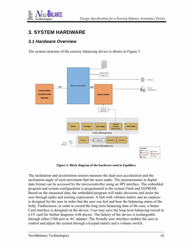
3.1 Hardware Overview The system structure of the sensory balancing device is shown in Figure 3.
Figure 3: Block diagram of the hardware used in Equilibra
The inclination and acceleration sensors measure the dual-axis acceleration and the inclination angle of each movement that the users make. The measurements in digital data format can be accessed by the microcontroller using an SPI interface. The embedded program and system configuration is programmed in the system Flash and EEPROM. Based on the measured data, the embedded program will make decisions and assist the user through audio and sensing expressions. A belt with vibrator matrix and an earpiece is designed for the user in order that the user can feel and hear the balancing status of the body. Furthermore, in order to record the long term balancing data of the user, a Smart Card interface is designed on the device. User may save the long term balancing record in a CF card for further diagnose with doctor. The battery of the device is rechargeable through either USB port or AC adapter. The friendly user interface enables the user to control and adjust the system through a keypad matrix and a volume switch.
10NewBalance Technologies

Design Specification for a Sensory Balance Assistance Device
3.2 Hardware Components In this section, the hardware components of Equilibra are described in detail. The main components are the microcontroller, accelerometer, audio codec, power supply, battery supply, vibrators and earphones.
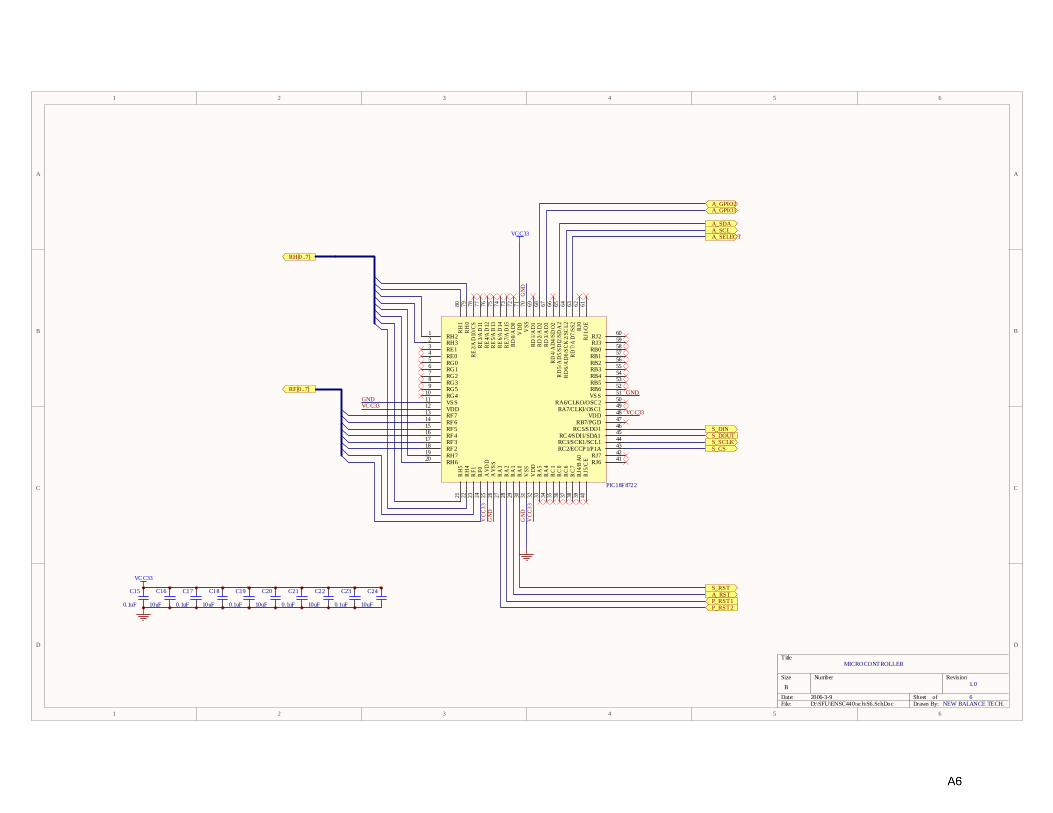
3.2.1 Microcontroller The PIC18F8722 microcontroller is used in the design of Equilibra. This processor has many advantages such as high computational performance and an economical price – with the addition of high endurance Enhanced Flash program memory. The PIC18F8722 microcontroller also provides an enhanced range of program memory options. It incorporates a range of serial communications peripherals, including 2 Master Synchronous Serial Port (MSSP) modules, capable of both SPI and I2C (Inter-Integrated Circuit) modes of operation. It also has a 16-bit External Memory Interface which allows the controller’s internal program counter to address a memory space of up to 2 Mbytes. . The PIC microcontroller communicates with the Accelerometer sensor, the Audio Codec, vibrators, Compact Flash (CF) memory card and User Interface. The microcontroller receives data from the sensor and processes this data. It then sends the appropriate signals to the Audio Codec and vibrators. The sensor and the CPU communicate via an SPI interface provided by one of the two MSSP serial modules. The SPI mode allows 8 bits of data to be synchronously transmitted and received simultaneously. The CPU communicates with the Audio Codec via the other provided MSSP serial port being set to the I2C interface mode. These MSSP interface modules can be assigned to either one of ports C or D of the microcontroller. The PIC microcontroller also controls the vibrators via I/O pins. The User Interface, which comprises of a set of buttons and LED’s, communicates with the CPU via I/O pins. Also, the CPU sends data to the CF card slot via its External Memory Interface pins which are assigned to ports F and H. The power supplied to the microcontroller is delivered by the Power Management module which is described in subsequent sections. The schematic for the PIC18F8722 microcontroller can be seen on page A7 of the Appendix.
11NewBalance Technologies

Design Specification for a Sensory Balance Assistance Device
3.2.2 Accelerometer PCB Programmable Dual axis accelerometer used in Equilibra is called ADIS 16201 from Analog Device, and it measures acceleration and inclination angle. The latter parameter is of interest to us as it will be used to measure how much the users have deviated from their balanced position. In choosing a device that would measure the inclination we also considered gyroscope as an inclination measurement device. While gyroscope offers better measurement accuracy, it requires higher power consumption. The voltage needed to operate a gyroscope (by Analog Device) is between 4.6 and 5.2 volts, while the standard voltage for a hand held device is 3.6 volts. Given the safety concerns associated with gyroscope, low power consumption and relatively low price of accelerometer, we have decided to use ADIS 16201 as the inclination measurement component for Equilibra.
The sensor measures tilt away from the “ideal” plane that is normal to the earth’s gravitational force. This calculation assumes that no force outside of the earth’s gravitational force is acting on the device. The sensor generates the inclination measures based on linear approximation of acceleration. The sensor measures a maximum 90° inclination in each of right, left, front and back directions. Figure 4 shows the output response versus the orientation of the sensor with respect to earth’s surface.
X_INCLOUT=+1148=90° Y INCLOUT=0
X_INCLOUT=0 Y_INCLOUT=+1148=90°
X_INCLOUT=0 Y_INCLOUT=-1148=-90°
X_INCLOUT=-1148=-90° Y_INCLOUT=0
Figure 2: Sensor's Output Response vs. Rotation
12NewBalance Technologies
13NewBalance Technologies
Design Specification for a Sensory Balance Assistance Device
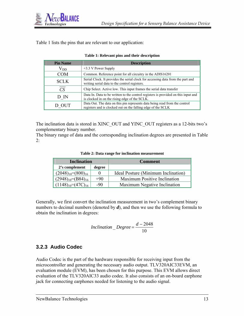
Table 1 lists the pins that are relevant to our application:
Table 1: Relevant pins and their description
Pin Name Description VDD +3.3 V Power Supply
COM Common. Reference point for all circuitry in the ADIS16201
SCLK Serial Clock. It provides the serial clock for accessing data from the part and writing serial data to the control registers.
CS Chip Select. Active low. This input frames the serial data transfer
D_IN Data In. Data to be written to the control registers is provided on this input and is clocked in on the rising edge of the SCLK.
D_OUT Data Out. The data on this pin represents data being read from the control registers and is clocked out on the falling edge of the SCLK
The inclination data is stored in XINC_OUT and YINC_OUT registers as a 12-bits two’s complementary binary number. The binary range of data and the corresponding inclination degrees are presented in Table 2:
Table 2: Data range for inclination measurement
Inclination Comment 2’s complement degree
(2048)10=(800)16 0 Ideal Posture (Minimum Inclination) (2948)10=(B84)16 +90 Maximum Positive Inclination (1148)10=(47C)16 -90 Maximum Negative Inclination
Generally, we first convert the inclination measurement in two’s complement binary numbers to decimal numbers (denoted by d), and then we use the following formula to obtain the inclination in degrees:
102048_ −
=dDegreenInclinatio
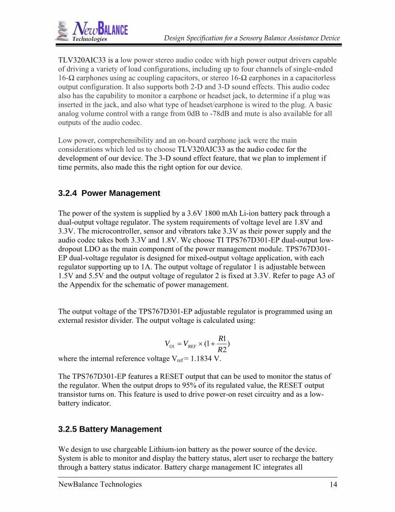
3.2.3 Audio Codec Audio Codec is the part of the hardware responsible for receiving input from the microcontroller and generating the necessary audio output. TLV320AIC33EVM, an evaluation module (EVM), has been chosen for this purpose. This EVM allows direct evaluation of the TLV320AIC33 audio codec. It also consists of an on-board earphone jack for connecting earphones needed for listening to the audio signal.
14NewBalance Technologies
Design Specification for a Sensory Balance Assistance Device
TLV320AIC33 is a low power stereo audio codec with high power output drivers capable of driving a variety of load configurations, including up to four channels of single-ended 16-Ω earphones using ac coupling capacitors, or stereo 16-Ω earphones in a capacitorless output configuration. It also supports both 2-D and 3-D sound effects. This audio codec also has the capability to monitor a earphone or headset jack, to determine if a plug was inserted in the jack, and also what type of headset/earphone is wired to the plug. A basic analog volume control with a range from 0dB to -78dB and mute is also available for all outputs of the audio codec. Low power, comprehensibility and an on-board earphone jack were the main considerations which led us to choose TLV320AIC33 as the audio codec for the development of our device. The 3-D sound effect feature, that we plan to implement if time permits, also made this the right option for our device.
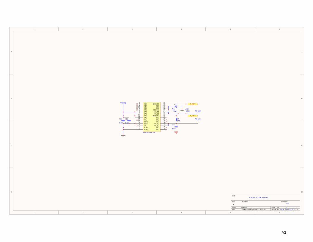
3.2.4 Power Management The power of the system is supplied by a 3.6V 1800 mAh Li-ion battery pack through a dual-output voltage regulator. The system requirements of voltage level are 1.8V and 3.3V. The microcontroller, sensor and vibrators take 3.3V as their power supply and the audio codec takes both 3.3V and 1.8V. We choose TI TPS767D301-EP dual-output low-dropout LDO as the main component of the power management module. TPS767D301-EP dual-voltage regulator is designed for mixed-output voltage application, with each regulator supporting up to 1A. The output voltage of regulator 1 is adjustable between 1.5V and 5.5V and the output voltage of regulator 2 is fixed at 3.3V. Refer to page A3 of the Appendix for the schematic of power management. The output voltage of the TPS767D301-EP adjustable regulator is programmed using an external resistor divider. The output voltage is calculated using:
)211(1 R
RVV REFO +×=
where the internal reference voltage Vref = 1.1834 V. The TPS767D301-EP features a RESET output that can be used to monitor the status of the regulator. When the output drops to 95% of its regulated value, the RESET output transistor turns on. This feature is used to drive power-on reset circuitry and as a low-battery indicator.
3.2.5 Battery Management We design to use chargeable Lithium-ion battery as the power source of the device. System is able to monitor and display the battery status, alert user to recharge the battery through a battery status indicator. Battery charge management IC integrates all

15NewBalance Technologies
Design Specification for a Sensory Balance Assistance Device
functionality required to safely charge rechargeable batteries to maximize capacity and minimize charge time. Single Li-Ion battery cell does not need protection from overcharge or over discharge conditions. In order to recharge the Lithium-ion battery, we designed a charging circuit with TI BQ24010DRC charge management IC, which has build-in current sensor, reverse blocking protection, high accuracy current and voltage regulation, charge status and charge termination features. It charges the battery in three phases: conditioning, constant current and constant voltage. It automatically restarts the charge if the battery voltage falls below an internal threshold and enters sleep mode when VCC supply is removed. A power good (PG) output indicates the presence of valid input power. Refer to page A5 of the Appendix for the schematic of battery management.
3.2.6 Earphones and Vibrators The corded earphones provided with the device have a flexible behind-the-ear wearing style with 2.5mm 4-pole stereo connector, which is compatible with the earphone jack of the device. Linear Vibrators will be mounted with sells on the front, back, left and right side of the belt to provide sensory signal in the direction of inclination. The power is supplied by system power management module. The On/Off status of the linear vibrators is controlled by the I/O ports of the microcontroller through MOSFET switches.
3.2.7 User Interface The User Interface consists of 3 buttons, 4 LED lights and a volume scroll to adjust the earphone volume level. The buttons are used to control the following system features:
• Power ON/OFF • Audio enable/disable • Vibrators enable/disable
The 3 push buttons are connected to the digital input ports of the microcontroller. The pull-down resistor pulls the microcontroller port pin to ground when the button is not pressed. A button press causes the port pin to be connected to +3.3V. Thus, only when the button is pressed will the microcontroller sense a logical one; otherwise the pin state will always be logical zero. There are 5 LED’s on the device to indicate the following status of the system:
• Power ON/OFF • Audio enable/disable • Vibrators enable/disable • Battery status • AC Charging Status
Design Specification for a Sensory Balance Assistance Device
3.3 Hardware Interconnections In this section, the hardware interconnections for Equilibra are described in detail. The main interconnections are those between the Accelerometer and Microcontroller, Audio Codec and Microcontroller and Compact Flash Card and Microcontroller.
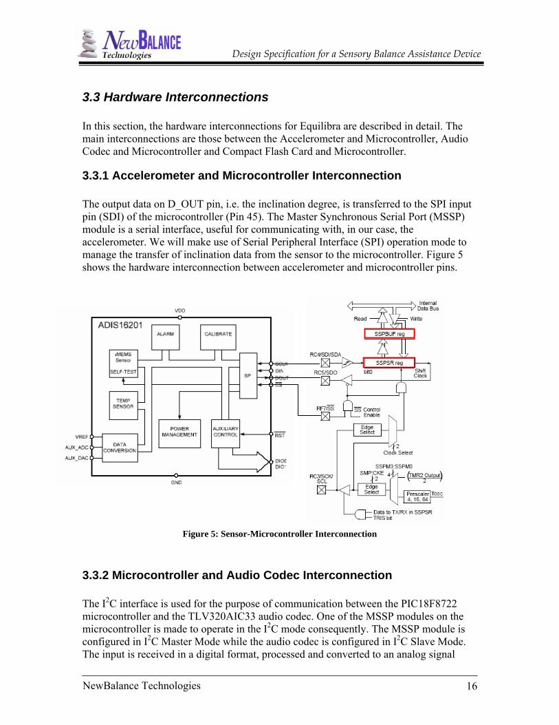
3.3.1 Accelerometer and Microcontroller Interconnection The output data on D_OUT pin, i.e. the inclination degree, is transferred to the SPI input pin (SDI) of the microcontroller (Pin 45). The Master Synchronous Serial Port (MSSP) module is a serial interface, useful for communicating with, in our case, the accelerometer. We will make use of Serial Peripheral Interface (SPI) operation mode to manage the transfer of inclination data from the sensor to the microcontroller. Figure 5 shows the hardware interconnection between accelerometer and microcontroller pins.
Figure 5: Sensor-Microcontroller Interconnection
3.3.2 Microcontroller and Audio Codec Interconnection The I2C interface is used for the purpose of communication between the PIC18F8722 microcontroller and the TLV320AIC33 audio codec. One of the MSSP modules on the microcontroller is made to operate in the I2C mode consequently. The MSSP module is configured in I2C Master Mode while the audio codec is configured in I2C Slave Mode. The input is received in a digital format, processed and converted to an analog signal
16NewBalance Technologies

Design Specification for a Sensory Balance Assistance Device
which is amplified, and sent out as the output to the earphones through the earphone jack on the audio codec EVM. The data is transferred in groups of 8 bits at a time. The first seven bits specify the register which is being written to or read. The important connections and the main pins used for the communication between the microcontroller and the audio codec are shown in Figure 6.
Figure 6: Audio Codec and Microcontroller Interface Diagram
17NewBalance Technologies
Design Specification for a Sensory Balance Assistance Device
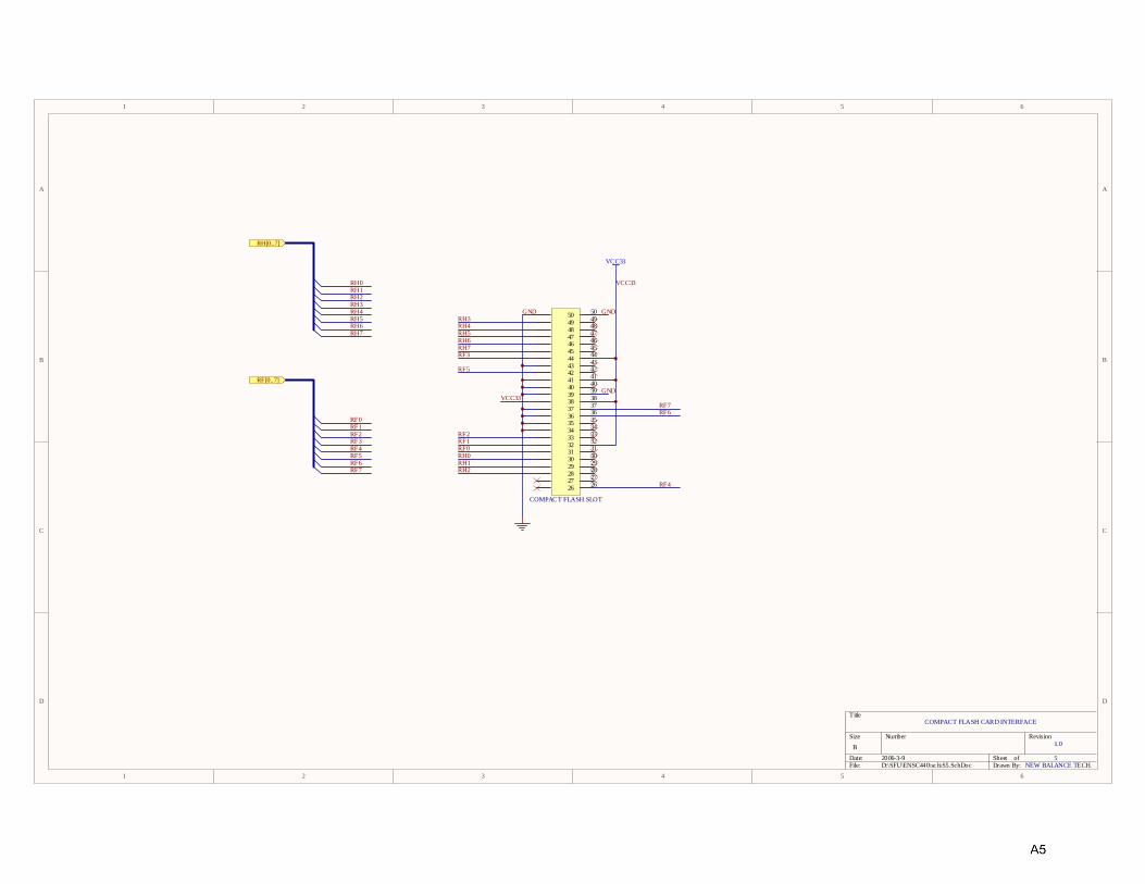
3.3.3 Compact Flash Card and Microcontroller Interconnection Compact Flash card is used as the external storage media for the Sensory Balance Assistance Device. The filtered inclination data will be stored in CF card as the historical record of the patient. The data saved in CF card can be read by a PC through a CF card reader with diagnostic software installed. Compact Flash card interface slot communicates with the PIC18F8722 microcontroller via system bidirectional digital I/O ports (RF0~7 and RH0~7). The microcontroller is able to detect when Compact Flash card is inserted through RF4. The working voltage of CF card is 3.3V DC, which is supplied by the system power management module through a voltage regulator. The voltage level of data lines from microcontroller to CF card slot does not need to be adjusted. Refer to page A6 of the Appendix for the schematic of the Compact Flash Card.
18NewBalance Technologies

Design Specification for a Sensory Balance Assistance Device
4. FIRMWARE DESIGN The overall algorithm on which the Equilibra system operates can be seen in the flowchart below.
Figure 7: Overall System Algorithm
19NewBalance Technologies
20NewBalance Technologies
Design Specification for a Sensory Balance Assistance Device
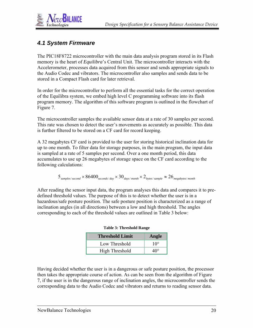
4.1 System Firmware The PIC18F8722 microcontroller with the main data analysis program stored in its Flash memory is the heart of Equilibra’s Central Unit. The microcontroller interacts with the Accelerometer, processes data acquired from this sensor and sends appropriate signals to the Audio Codec and vibrators. The microcontroller also samples and sends data to be stored in a Compact Flash card for later retrieval. In order for the microcontroller to perform all the essential tasks for the correct operation of the Equilibra system, we embed high level C programming software into its flash program memory. The algorithm of this software program is outlined in the flowchart of Figure 7. The microcontroller samples the available sensor data at a rate of 30 samples per second. This rate was chosen to detect the user’s movements as accurately as possible. This data is further filtered to be stored on a CF card for record keeping. A 32 megabytes CF card is provided to the user for storing historical inclination data for up to one month. To filter data for storage purposes, in the main program, the input data is sampled at a rate of 5 samples per second. Over a one month period, this data accumulates to use up 26 megabytes of storage space on the CF card according to the following calculations:
monthmegabytessamplebytesmonthdaysdayondsondsamples ////secsec/ 26230864005 ≈××× After reading the sensor input data, the program analyses this data and compares it to pre-defined threshold values. The purpose of this is to detect whether the user is in a hazardous/safe posture position. The safe posture position is characterized as a range of inclination angles (in all directions) between a low and high threshold. The angles corresponding to each of the threshold values are outlined in Table 3 below:
Table 3: Threshold Range
Threshold Limit Angle Low Threshold 10° High Threshold 40°
Having decided whether the user is in a dangerous or safe posture position, the processor then takes the appropriate course of action. As can be seen from the algorithm of Figure 7, if the user is in the dangerous range of inclination angles, the microcontroller sends the corresponding data to the Audio Codec and vibrators and returns to reading sensor data.
Design Specification for a Sensory Balance Assistance Device
If the user is in a safe posture position, the program then checks to see if the warning signals were previously activated or not. If they were not activated, it does nothing and continues on reading the data from the sensor. If the signals were triggered and the user has now returned to a safe position, the microcontroller puts the signals off and continues to read the sensor input data. To efficiently read data from the Accelerometer and send output signals to the Audio Codec, a series of interfacing modules have been defined. These main software modules are the interfacing between the Accelerometer and the PIC microcontroller and the interfacing between the PIC microcontroller and the Audio Codec which are described in later sections.
4.2 Accelerometer and Microcontroller Interfacing As mentioned earlier, inclination data is transmitted from D_OUT pin of the accelerometer to the SDI pin of the PIC18F8722 microcontroller. The operation of SPI and the software application that would implement the transfer of data are described by the algorithm depicted in Figure 8.
21NewBalance Technologies

22NewBalance Technologies
Design Specification for a Sensory Balance Assistance Device
Figure 8: Algorithm for data transfer between the Accelerometer and Microcontroller
First, the control bits in the SSPCON register and two MSB in the SSPSTAT enable us to set the following parameters:
• Master mode (SCK is the clock output) • Slave mode (SCK is the clock input) • Clock Polarity (Idle state of SCK) • Data input sample phase (middle or end of data output time) • Clock edge (output data on rising/falling edge of SCK) • Clock Rate (Master mode only) • Slave Select mode (Slave mode only)
Then, we use the SSP Enable bit to enable serial port and SPI I/O.
One bit of data is shifted into SSPSR
and hold in SSPBUF.
START
Is SSPBUF/SSPSR
full? (Buffer Full
Detect - BF= 1)?
NO
YES
SSBUF content is read and transmitted to Flash Program Memory
Set BF = 0
Enable Serial Port
Design Specification for a Sensory Balance Assistance Device
Each bit of the binary number representing inclination degree is shifted to device by SSPSR starting with the MSB. Since SSPSR is not directly writeable or readable, SSPBUF hold the data until SSPSR is full (8 bits of data are received) at which point BF (Buffer Full Detect which is the Bit0 of SSPSTAT) is set to 1. We check the Status flag, BF, constantly to determine whether SSPBUF is full; if the condition is met, the data is transferred to Flash Program Memory. When the SSBUF is read, BF is cleared (set to “0”).
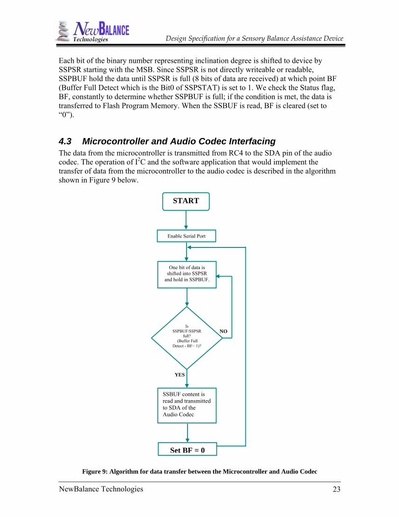
4.3 Microcontroller and Audio Codec Interfacing The data from the microcontroller is transmitted from RC4 to the SDA pin of the audio codec. The operation of I2C and the software application that would implement the transfer of data from the microcontroller to the audio codec is described in the algorithm shown in Figure 9 below.
One bit of data is
shifted into SSPSR and hold in SSPBUF.
Is SSPBUF/SSPSR
full? (Buffer Full
Detect - BF= 1)?
NO
YES
SSBUF content is read and transmitted to SDA of the Audio Codec
Set BF = 0
Enable Serial Port
START
Figure 9: Algorithm for data transfer between the Microcontroller and Audio Codec
23NewBalance Technologies

Design Specification for a Sensory Balance Assistance Device
The data received from the microcontroller is interpreted to determine the type of audio signal which needs to be generated in the attached earphones. Different audio signals are produced, depending on the direction of inclination of the person using the device. Bits in the data will also be interpreted to determine the volume of the signal along with the tone and target of the output audio signal, i.e. left/right/both earphones.
24NewBalance Technologies

Design Specification for a Sensory Balance Assistance Device
5. TEST PLANS To layout test plans, we make use of the functional specifications document. The following test measures are planned to make sure the corresponding requirement is met. Due to resource constraints, we are not to test the device under very extreme condition. [Rn] indicates requirement number n in the functional specifications document.
5.1 Environmental Test Plans The unit device, Equilibra, as well as individual components like audio codec and accelerometer will be tested in temperature ranging from -10ºC in locations such as Cypress Mountain to meet [R8]. It will be tested both on the sea level (on Pacific Coast) to higher elevations on Mount Cypress where pressure is lower to meet [R9].
5.2 Accuracy Test Plans To meet requirements 10 and 12, the accelerometer will be tested under different ranges of motion to make sure it is sensitive enough. The user will be asked to assume different postures, and measurements will be made to ascertain the actual inclination angle matches the inclination measurement with an accuracy of ±8°. A test subject, an individual preferably with balance disorder, will use the device. The user will assume postures that are potentially dangerous without prior notice and as fast as possible. The reaction time of the device will be measured to make sure the device will meet [R13].
5.3 Reliability Test Plans The device will be turned on operated for a period of 48-72 hour to ensure longevity of operation requirement [R14] has been met.
5.4 Components Test Plans The memory card will be read to make sure it contains the data collected from the device [R19]. Maximum audio and vibratory signal will be subject to measurement to make sure they meet safety standards laid out by [R27].
25NewBalance Technologies

Design Specification for a Sensory Balance Assistance Device
To meet [R36] battery of different strengths (fully charged and low) will be used, and the LEDs corresponding to each status will be checked to make sure the appropriate LED turns on when battery is low or fully charged.
5.5 Documentation Test Plans A person with minimal technical background will be asked to review and assess the usability of the documents and literature, such as manuals, provided in junction with Equilibra. The individual’s understanding of the materials will be tested by the team members to make sure the documentation is user friendly and free of ambiguities as outlined by requirements 38-44.
26NewBalance Technologies

Design Specification for a Sensory Balance Assistance Device
6. CONCLUSION The Design Specification outlines the design approaches that will be adopted to meet the requirements for a reliable and user friendly Equilibra. The specifications span hardware, software, user interface, and power management, as well as test plans that will ensure requirements set in Functional Specification document are met.
Although some of these specifications may be altered to account f, this document will serve as the primary reference for development of Equilibra. The expected completion date for implementation of design is April 7, 2006.
27NewBalance Technologies
Design Specification for a Sensory Balance Assistance Device
7. REFERENCES 1. American Institute of Balance: www.dizzy.com 2. Vestibular Disorders Association: www.vestibular.org 3. Balance and Disorder Society-Vancouver, BC: www.balanceanddizziness.org 4. Journal of NeuroEngineering and Rehabilitation 2005: www.jneuroengrehab.com 5. Parkinson Society Canada: www.parkinson.ca 6. Digi-Key Corporation: www.digikey.com 7. Texas Instruments, Low Power Stereo Audio Codec for Portable
Audio/Telephony. [Online]: http://focus.ti.com/docs/prod/folders/print/tlv320aic33.html
8. Texas Instruments, Military Enhanced Plastic Dual-Output Low-Dropout Voltage Regulators. [Online]: http://focus.ti.com/docs/prod/folders/print/tps767d301-ep.html 9. Texas Instruments, Single-Chip, Li-Ion Charge Management IC For Handheld Applications. [Online]: http://focus.ti.com/docs/prod/folders/print/bq24010.html 10. Microchip, PIC18F8722 Family Data Sheet. [Online]: http://ww1.microchip.com/downloads/en/DeviceDoc/39646b.pdf 11. Analog Devices, ADIC16201 Programmable Dual-Axis Inclinometer/Accelerometer.[Online]: http://www.analog.com/UploadedFiles/Data_Sheets/401679848ADIS16201_prc.pdf
28NewBalance Technologies

1
1
2
2
3
3
4
4
5
5
6
6
D D
C C
B B
A A
B 1
1 2 3
CS 4 5 6 7 9
13 12 14 15 11
8 10 16
C1
C2
Title
Number Revision Size
Date: 2006-3-9 Sheet of File: D:\SFU\ENSC440\sc h\S1.SchDoc Drawn By:
SENSOR
1.0
NEW BALANCE TECH.
SCLK DOUT
DIN
DIO0 DIO1 DNC RS T
VDD DAC ADC VR EF DNC AUX C OM AUX C OM COM
ADIS 16201 VC C33
1uF
S_SC LK S_DOUT
S_CS
S_RS T 1uF
VC C33 S_DIN

1
1
2
2
3
3
4
4
5
5
6
6
D D
C C
B B
A A
B
14 11 10
9 8 7 6 5 4 3
2 1
/
18 19 23 22 27 28 29 30 31 3213
12
J1
C7 C8 C9C5 C6C3 C4
2
Title
Number Revision Size
Date: 2006-3-9 Sheet of File: D:\SFU\ENSC440\sc h\S2.SchDoc Drawn By:
MIC3R MIC3L LINE2RM LINE2RP LINE2LM LINE2LP LINE1RM LINE1RP LINE1LM LINE1LP
A VD
D _A
D C
16
M C
L K
37
B C
LK
38
W C
LK
39
D IN
40
D
OU T
41
IO V
D D
44
D VD
D
36
D R
V D
D 24
D R
V D
D 17
A VD
D _D
A C
25
A VS
S_A
D C
15
M F
P 2
47
M F
P 3
48
M F
P 1
46
M F
P 0
45
S ELE
C T
43
S D A
S C
L
R E S
E T
33
G PI
O 1
35
G PI
O 2
34
I O D
V SS
42
D R V
SS
21
D R V
SS
20
A VS
S_D
A C
26
HP LOUT HP LCOM HP ROUT HP RCOM
MONO_LOP MONO_LOM
LEFT_LOP LEFT_LOM
RIGHT_LOP RIGHT_LOM MICBIAS
MICDET
TLV320AIC33IR GZ
HEADSET OUTPUT
A_GPIO2 A_GPIO1 A_RS T
A_SCL A_SDA A_SELECT
VC C18
VCC33 VC C33 VC C33
0.1uF 10uF 0.1uF 10uF
C10
0. 1uF 10uF
VCC33
0.1uF 10uF
VCC18
AUDIO CODEC
1.0
NEW BALANCE TECH.
1
1
2
2
3
3
4
4
5
5
6
6
D D
C C
B B
A A
B
28 NC 27
NC 26 /NC 25
24 23 22
NC 21 NC 20 NC 19
18 17
NC 16 NC 15
NC1 NC2
NC13 NC7
5 6
11 12
NC14 10
4 NC8
3 9
R3
R1
R2
R4
3
Title
Number Revision Size
Date: 2006-3-9 Sheet of File: D:\SFU\ENSC440\sc h\S3.SchDoc Drawn By:
RESET1
FB1OUT1 OUT1
RESET2
OUT2 OUT2
IN1 IN1 IN2 IN2
EN2 EN1
GND GND
TPS767D301-EP
VCC36
0.1uF
C11
0. 1uF
C12
10uF
C13
VC C33 250K
P_RS T2
VC C18 15.6K
30K
250K
P_RS T1
POWER MANAGEMENT
1.0
NEW BALANCE TECH.

1
1
2
2
3
3
4
4
5
5
6
6
D D
C C
B B
A A
B
6PG 7 TS 8
9 10
5 4
3
IN1 2
+ 1K 1K 1K
12
12
12
+
1K
- 2+1
4
Title
Number Revision Size
Date: 2006-3-9 Sheet of File: D:\SFU\ENSC440\sc h\S4.SchDoc Drawn By:
BATTERY MANAGEMENT
ISET
BAT OUT
VS S STAT2
STAT1
VCC
BQ24010DRC
AC JACK
0.47uF C105
R101 R102 R103
D101
D102
D103
C106
R104
BATTERY + BATTERY
LI-ION BATTRY CELL
BATTERY +
1.0
NEW BALANCE TECH.
VCC36
112233
44556677
889910101111
12121313141415151616171718181919202021212222232324242525
1
1
2
2
3
3
4
4
5
5
6
6
D D
C C
B B
A A
B
26 2627 2728 2829 2930 3031 3132 3233 3334 3435 3536 3637 3738 3839 3940 4041 4142 4243 4344 4445 4546 4647 4748 4849 4950 50 RH3 RH4 RH5 RH6 RH7
RH0 RH1 RH2
[
[
5
Title
Number Revision Size
Date: 2006-3-9 Sheet of File: D:\SFU\ENSC440\sc h\S5.SchDoc Drawn By:
COMPAC T FLASH SLOT
VCC33
GND
GND VCC33
VCC33
GND
RF3
RF5
RF2 RF1 RF0
RF7 RF6
RF4
RH0 RH1 RH2 RH3 RH4 RH5 RH6 RH7
RF0 RF1 RF2 RF3 RF4 RF5 RF6 RF7
RH 0..7]
RF 0..7]
COMPACT FLASH CARD INTERFACE
1.0
NEW BALANCE TECH.
1
1
2
2
3
3
4
4
5
5
6
6
D D
C C
B B
A A
B
54 53 52 51
/ / 50 / / 49
48 / 47
/ 46 / / 45 / / 44 / / 43
42 41
55 56 57 58 59 60/
/ /
/ /
/ /
//
/ ///// /////
//
//
1 2 3 4 5 6 7 8 9
10 11 12 13 14 15 16 17 18 19 20
RH[
[
6
Title
Number Revision Size
Date: 2006-3-9 Sheet of File: D:\SFU\ENSC440\sc h\S6.SchDoc Drawn By:
RB4 RB5 RB6 VS S
RA6 CLKO OSC2 RA7 CLKI OSC1
VDD RB7 PGD
RC5 S DO1 RC 4 SDI1 SDA1 RC3 SCK1 SCL1 RC2 ECCP 1 P1A
RJ7 RJ6
RB3 RB2 RB1 RB0 RJ3 RJ2 RJ
1O
E 61
RJ
0 62
RD
7A
D7 S
S2
63
R D
6A
D 6
S CK
2SC
L2
64
R D
5A
D 5
S D I2
SD
A 2
65
RD 4
A D4
SD
O2
66
RD 3
A D3
67
RD
2A
D2
68
RD 1
A D1
69
V
SS
70
V DD
71
RD
0A
D0
72
RE 7
A D
15
73
RE 6
A D
14
74
RE 5
A D
13
75
RE 4
A D
12
76
RE 3
A D
11
77
RE 2
A D
10CS
78
R
H 0
79
R H
1 80
R J 5
C E
40
R J 4
B A0
39
R
C 7
38
R C
6 37
R
C 0
36
R C
1 35
R
A 4
34
R A
5 33
V
DD
32
V SS
31
R
A 0
30
R A
1 29
R
A 2
28
R A
3 27
A
VD D
25
A
VS S
26
R F0
24
R
F1
23
R H
4 22
R
H 5
21
RH2 RH3 RE1 RE0 RG0 RG1 RG2 RG3 RG5 RG4 VS S VDD RF 7 RF 6 RF 5 RF 4 RF 3 RF 2 RH7 RH6
PIC18F 8722
0..7]
RF 0..7]
GND VC C33
V CC
3 3
G ND
S_SCLK S_DOUT S_DIN
S_CS
S_RST
A_SCL A_SDA
A_SELECT
A_RST
V C
C 3 3
G
ND
A_GPIO2 A_GPIO1
VCC33
G ND
P_RST1 P_RST2
GND
VC C33
0.1uF
C17
10uF
C18
0.1uF
C19
10uF
C20
0.1uF
C15
10uF
C16
VC C33
0.1uF
C21
10uF
C22
0.1uF
C23
10uF
C24
MICROCONTROLLER
1.0
NEW BALANCE TECH.

Symbol Description
Headphone
Volume Control
Power ON/OFF
Battery Strength
Vibration Jock
Vibration Enable/Disable
Audio Enable/Disable
A/C Indicator
8.5 cm
6.2 cm
2 cm
NewBalance Technologies