school bus lot, support building & practice field
TRANSCRIPT

Prepared By:
SCHOOL BUS LOT, SUPPORT BUILDING & PRACTICE FIELD
South Guy Road Arlington, TN 38002
April 5, 2018
A2H # 17439

School Bus Lot, Support Building & Practice Field Bartlett City Schools A2H - Project No. 17439 00 0107 - 1 April 5, 2018
SECTION 00 0107
SEALS PAGE
CIVIL ENGINEER:
JASON D. DITTRICH, PE
A2H, INC.
3009 DAVIES PLANTATION ROAD
LAKELAND, TN 38002
PHONE: (901) 372-0404
FAX: (901) 373-4002
LANDSCAPE ARCHITECT:
CHET A. WINSTEAD
A2H, INC.
3009 DAVIES PLANTATION ROAD
LAKELAND, TN 38002
PHONE: (901) 372-0404
FAX: (901) 373-4002
ARCHITECT:
STAN W. ROWLAND, II, RA
A2H, INC.
3009 DAVIES PLANTATION ROAD
LAKELAND, TN 38002
PHONE: (901) 372-0404
FAX: (901) 373-4002

SECTION 00 0107 SEALS PAGE
School Bus Lot, Support Building & Practice Field Bartlett City Schools A2H - Project No. 17439 00 0107 - 2 April 5, 2018
STRUCTURAL ENGINEER:
RYAN McDANIEL, PE
A2H, INC.
3009 DAVIES PLANTATION ROAD
LAKELAND, TN 38002
PHONE: (901) 372-0404
FAX: (901) 373-4002
MECHANICAL / PLUMBING ENGINEER:
BENNIE R. ALLEN, JR., PE
A2H, INC.
3009 DAVIES PLANTATION ROAD
LAKELAND, TN 38002
PHONE: (901) 372-0404
FAX: (901) 373-4002
ELECTRICAL ENGINEER:
DANNY H. LANGSTON, PE
A2H, INC.
3009 DAVIES PLANTATION ROAD
LAKELAND, TN 38002
PHONE: (901) 372-0404
FAX: (901) 373-4002
END OF SECTION

School Bus Lot, Support Building & Practice FieldBartlett City SchoolsA2H - Project No. 17439 00 0110 - 1 April 5, 2018
SECTION 00 0110TABLE OF CONTENTS
PROCUREMENT AND CONTRACTING REQUIREMENTSDIVISION 00 -- PROCUREMENT AND CONTRACTING REQUIREMENTS
00 0107 - Seals Page00 0110 - Table of Contents00 0115 - List of Drawing Sheets
SPECIFICATIONSDIVISION 01 -- GENERAL REQUIREMENTS
01 1000 - Summary01 2000 - Price and Payment Procedures01 2200 - Unit Prices01 2500 - Substitution Procedures01 2664 - Weather Days01 3000 - Administrative Requirements01 4000 - Quality Requirements01 4100 - Regulatory Requirements01 4216 - Definitions01 5000 - Temporary Facilities and Controls01 5713 - Temporary Erosion and Sediment Control01 6000 - Product Requirements01 6116 - Volatile Organic Compound (VOC) Content Restrictions01 7000 - Execution and Closeout Requirements01 7800 - Closeout Submittals01 7900 - Demonstration and Training
DIVISION 02 -- EXISTING CONDITIONS 02 3000 - Subsurface Conditions02 4100 - Demolition
DIVISION 03 -- CONCRETE 03 0505 - Underslab Vapor Barrier03 1000 - Concrete Forming and Accessories03 2000 - Concrete Reinforcing03 3000 - Cast-in-Place Concrete
DIVISION 04 -- MASONRY 04 0511 - Masonry Mortaring and Grouting04 2001 - Masonry Veneer
DIVISION 05 -- METALS 05 5000 - Metal Fabrications
DIVISION 06 -- WOOD, PLASTICS, AND COMPOSITES 06 0573 - Wood Treatment06 1000 - Rough Carpentry06 1753 - Shop-Fabricated Wood Trusses
SECTION 00 0110 TABLE OF CONTENTS
School Bus Lot, Support Building & Practice FieldBartlett City SchoolsA2H - Project No. 17439 00 0110 - 2 April 5, 2018
06 4100 - Architectural Wood CaseworkDIVISION 07 -- THERMAL AND MOISTURE PROTECTION
07 2119 - Foamed-In-Place Insulation07 6200 - Sheet Metal Flashing and Trim07 9200 - Joint Sealants
DIVISION 08 -- OPENINGS 08 1113 - Hollow Metal Doors and Frames08 1416 - Flush Wood Doors08 4313 - Aluminum-Framed Storefronts08 5680 - Aluminum Pass-Thru Sliding Servcie Windows08 7100 - Door Hardware
DIVISION 09 -- FINISHES 09 0000 - Material Color Schedule09 2116 - Gypsum Board Assemblies09 3000 - Tiling09 5100 - Acoustical Ceilings09 6500 - Resilient Flooring09 9000 - Painting and Coating
DIVISION 10 -- SPECIALTIES 10 2800 - Toilet, Bath, and Laundry Accessories
DIVISION 12 -- FURNISHINGS 12 2113 - Horizontal Louver Blinds12 3600 - Countertops
DIVISION 13 -- SPECIAL CONSTRUCTION 13 3419 - Metal Building Systems
DIVISION 22 -- PLUMBING 22 0553 - Identification for Plumbing Piping and Equipment22 0719 - Plumbing Piping Insulation22 1005 - Plumbing Piping22 1500 - General-Service Compressed-Air Systems22 4000 - Plumbing Fixtures
DIVISION 23 -- HEATING, VENTILATING, AND AIR-CONDITIONING (HVAC) 23 0500 - Common Work Results for HVAC23 0513 - Common Motor Requirements for HVAC Equipment23 0548 - Vibration and Seismic Controls for HVAC Piping and Equipment23 0553 - Identification for HVAC Piping and Equipment23 0593 - Testing, Adjusting, and Balancing for HVAC23 0913 - Instrumentation and Control Devices for HVAC23 0923 - Direct-Digital Control System for HVAC23 3700 - Air Outlets and Inlets23 8127 - Small Split-System Heating and Cooling

SECTION 00 0110 TABLE OF CONTENTS
School Bus Lot, Support Building & Practice FieldBartlett City SchoolsA2H - Project No. 17439 00 0110 - 3 April 5, 2018
DIVISION 26 -- ELECTRICAL 26 0100 - General Provisions - Electrical26 0519 - Low-Voltage Electrical Power Conductors and Cables26 0526 - Grounding and Bonding for Electrical Systems26 0529 - Hangers and Supports for Electrical Systems26 0533.13 - Conduit for Electrical Systems26 0533.16 - Boxes for Electrical Systems26 0548 - Vibration and Seismic Controls for Electrical Systems and Equipment26 0553 - Identification for Electrical Systems26 0583 - Wiring Connections26 2416 - Panelboards26 2726 - Wiring Devices26 2816.16 - Enclosed Switches26 5100 - Interior Lighting26 5600 - Exterior Lighting
DIVISION 28 -- ELECTRONIC SAFETY AND SECURITY 28 4600 - Fire Detection and Alarm
DIVISION 31 -- EARTHWORK 31 1000 - Site Clearing31 2200 - Grading31 2316 - Excavation31 2316.13 - Trenching31 2323 - Fill31 3700 - Riprap
DIVISION 32 -- EXTERIOR IMPROVEMENTS 32 1313 - Concrete Paving32 1713 - Parking Bumpers32 1723.13 - Painted Pavement Markings32 3113 - Chain Link Fences and Gates32 8423 - Underground Sprinklers32 9223 - Sodding32 9300 - Plants
DIVISION 33 -- UTILITIES 33 0110.58 - Disinfection of Water Utility Piping Systems33 0513 - Manholes and Structures33 1416 - Site Water Utility Distribution Piping33 3113 - Site Sanitary Sewerage Gravity Piping33 4211 - Stormwater Gravity Piping
DIVISION 43 -- PROCESS GAS AND LIQUID HANDLING, PURIFICATION AND STORAGEEQUIPMENT
43 4000 - Above Ground Storage TanksEND OF SECTION 00 0110

SECTION 00 0110 TABLE OF CONTENTS
School Bus Lot, Support Building & Practice FieldBartlett City SchoolsA2H - Project No. 17439 00 0110 - 4 April 5, 2018

School Bus Lot, Support Building & Practice FieldBartlett City SchoolsA2H - Project No. 17439 00 0115 - 1 April 5, 2018
SECTION 00 0115LIST OF DRAWINGS SHEETS
1.01 DESCRIPTIONA. The following is the list of Project Contract Drawings entitled School Bus Lot, Support Building &
Practice Field for Bartlett City Schools in Bartlett, Tennessee, dated March 12, 2018 withRevision dates, if any as noted.
SHEETNUMBER
SHEET NAME REVISIONDATE
GENERALG0.0 COVER SHEETG0.1 PROJECT DATA AND NOTESG0.2 LIFE SAFETY PLANCIVILC0.1 EXISTING CONDITIONSC1.0 DEMOLITION PLANC2.0 SITE LAYOUT PLANC2.1 DIESEL FUEL DEPOT LAYOUTC3.0 GRADING AND DRAINAGE PLANC3.1 DETAILED SPOT ELEVATIONSC3.2 LAYOUT AND GRADING POINT TABLEC4.0 EROSION CONTROL PLAN (PHASE I)C4.1 EROSION CONTROL PLAN (PHASE II)C4.2 EROSION CONTROL PLAN (PHASE III)C4.3 EROSION CONTROL DETAILSC4.4 SEDIMENT BASIN DETAILSC5.0 SITE UTILITY PLANC6.0 SITE DETAILSC6.1 SITE DETAILSC6.2 SITE DETAILSLANDSCAPINGL1.0 PLANTING PLANL1.1 PLANTING DETAILSL2.0L2.1
IRRIGATION PLANIRRIGATION DETAILS
ARCHITECTURALA1.1 FLOOR PLAN AND ROOF PLANA2.1 EXTERIOR ELEVATIONSA3.1 BUILDING SECTIONS AND INTERIOR SECTIONS/DETAILSA4.1 WALL SECTIONSA6.1 DOOR SCHEDULE AND WINDOW ELEVATIONA7.1 FINISH SCHEDULE AND DETAILSA8.1 REFLECTED CEILING PLANSTRUCTURALS0.1S0.2S1.1S1.2S2.1
GENERAL NOTESQUALITY ASSURANCE PLANFOUNDATION AND ROOF FRAMING PLANSFUEL ISLAND PLAN AND DETAILSBUILDING SECTIONS AND DETAILS
MECHANICAL

SECTION 00 0115 LIST OF DRAWINGS SHEETS
School Bus Lot, Support Building & Practice FieldBartlett City SchoolsA2H - Project No. 17439 00 0115 - 2 April 5, 2018
M1.1M2.1M3.1
HVAC FLOOR PLANHVAC DETAILSHVAC SCHEDULES
PLUMBINGP1.1 PLUMBING FLOOR PLANP2.1 PLUMBIND FIXTURE SCHEDULE AND DETAILSELECTRICALE0.1E1.0E1.1E2.1E2.2
ELECTRICAL LEGEND AND NOTESELECTRICAL-SITE PLANELECTRICAL-FLOOR PLANSELECTRICAL DETAILSPANELBOARD SCHEDULES AND RISER DIAGRAM
END OF SECTION 00 0115
School Bus Lot, Support Building & Practice FieldBartlett City SchoolsA2H - Project No. 17439 01 1000 - 1 April 5, 2018
SECTION 01 1000SUMMARY
PART 1 GENERAL1.01 PROJECT
A. Project Name: School Bus Lot, Support Building & Practice FieldB. Owner's Name: Bartlett City Schools.C. Architect/Engineer's Name: A2H.D. The Project consists of the construction of a Dispatch Building, a Bus Diesel Fuel Depot, Bus
paved parking lot, Site Utilities, a Practice Field and related Sitework as described in thedrawings and project manual.
1.02 DESCRIPTION OF CONSTRUCTION WORKA. Scope of construction work is shown on drawings and specified in other sections and includes:
Civil, Landscape, Architectural, Structural, HVAC, Plumbing and Electrical.B. Notice: In no event is a product to be used in this project known to contain any hazardous or
toxic waste or material, radioactive materials, or other contaminants, the removal of which isrequired or the maintenance of which is prohibited, regulated or penalized by any local, state, orfederal agency, authority or governmental unit. If any product is inadvertently specified whichcontains such materials, it is the Contractor’s, subcontractor’s and supplier’s obligation and dutyto advise the Architect/Engineer of this fact prior to the ordering and/or installing of the productor material.
1.03 DESCRIPTION OF ALTERATIONS WORKA. Scope of demolition and removal work is indicated on drawings and specified in Section 02
4100.B. Hazardous Substances: Discovery of a suspected dangerous or hazardous substance during
construction stops construction operations and may seriously delay a project. Contractors oftenencounter asbestos, lead, polychlorinated biphyenyls (PCBs), and similar hazardous materialson their construction projects. Because the use of those materials was common until recently,they are often found on renovation projects involving older buildings. AIA Document A201outlines procedures contractors must follow when suspected dangerous or hazardoussubstances are uncovered during construction. If the suspect material proves to be adangerous or hazardous substance, a contractor is not permitted to resume constructionoperations until the material has been rendered harmless or has been lawfully removed fromthe site.
C. Scope of alterations work is indicated on drawings.1.04 OWNER OCCUPANCY
A. Owner intends to occupy the Project upon Substantial Completion.B. Cooperate with Owner to minimize conflict and to facilitate Owner's operations.C. Schedule the Work to accommodate Owner occupancy.
1.05 CONTRACTOR USE OF SITE AND PREMISESA. Construction Operations: Limited to areas noted on Drawings. B. Arrange use of site and premises to allow:
1. Owner occupancy.2. Work by Others.3. Work by Owner.4. Use of site and premises by the public.
C. Provide access to and from site as required by law and by Owner:
SECTION 01 1000 SUMMARY
School Bus Lot, Support Building & Practice FieldBartlett City SchoolsA2H - Project No. 17439 01 1000 - 2 April 5, 2018
1. Emergency Building Exits During Construction: Keep all exits required by code openduring construction period; provide temporary exit signs if exit routes are temporarilyaltered.
2. Do not obstruct roadways, sidewalks, or other public ways without permit.D. Existing building spaces may not be used for storage.E. Time Restrictions:
1. Limit conduct of especially noisy, malodorous, and dusty exterior work to the hours of 4:00PM to 6:00 PM weekdays.
F. Utility Outages and Shutdown:1. Limit disruption of utility services to hours the building is unoccupied.2. Do not disrupt or shut down life safety systems, including but not limited to fire sprinklers
and fire alarm system, without 7 days notice to Owner and authorities having jurisdiction.3. Limit shutdown of utility services to 4 hours at a time, arranged at least 24 hours in
advance with Owner.4. Prevent accidental disruption of utility services to other facilities.
1.06 ACCIDENT PREVENTIONA. Contractor shall comply with safety and engineering practices set forth in "Manual of Accident
Prevention in Construction", published by Associated General Contractors of America and withall applicable state and local safety and sanitary laws, regulations and ordinances, as well asestablished safety rules and practices of Owner. Contractor shall, at his own expense, properlyprotect Owner's property from injury and shall make good any damage to same caused byfailure to exercise required care during this work.
B. Contractor shall provide properly maintained warning signs, lights, barricades, railing and othersafeguards for protection of workmen and others on or about or adjacent to the work.
C. Contractor shall provide his employees with approved eye protection, protective head gear, etc.,while performing work required for this project.
1.07 FIRE-PREVENTION AND PROTECTIONA. Contractor shall take all necessary precautions to guard against and eliminate all possible fire
hazards and to prevent damage to any work, equipment and building.B. No welding, flame cutting or other operations involving use of flame, arcs or sparking devices
shall be allowed without adequate protection and shielding. All combustible or flammablematerial shall be removed from immediate working area and shall be adequately protected withasbestos fire blankets or suitable noncombustible shields. Further, Contractor shall providenecessary personnel and fire fighting equipment to effectively control incipient fire resulting fromwelding, flame cutting or other operation required for demolition work.
1.08 SPECIFICATION SECTIONS APPLICABLE TO ALL CONTRACTSA. Unless otherwise noted, all provisions of the sections listed below apply to all contracts.
Specific items of work listed under individual contract descriptions constitute exceptions.B. Section 01 2000 - Price and Payment Procedures.C. Section 01 2500 - Substitution Procedures.D. Section 01 3000 - Administrative Requirements.E. Section 01 4000 - Quality Requirements.F. Section 01 4100 - Regulatory Requirements.G. Section 01 4216 - Definitions.H. Section 01 5000 - Temporary Facilities and Controls.I. Section 01 5713 - Temporary Erosion and Sediment Control.J. Section 01 6000 - Product Requirements.K. Section 01 6116 - Volatile Organic Compound (VOC) Content Restrictions.

SECTION 01 1000 SUMMARY
School Bus Lot, Support Building & Practice FieldBartlett City SchoolsA2H - Project No. 17439 01 1000 - 3 April 5, 2018
L. Section 01 7000 - Execution and Closeout Requirements.M. Section 01 7800 - Closeout Submittals.N. Section 01 7900 - Demonstration and Training.
PART 2 PRODUCTS - NOT USEDPART 3 EXECUTION - NOT USED
END OF SECTION 01 1000

School Bus Lot, Support Building & Practice FieldBartlett City SchoolsA2H - Project No. 17439 01 2000 - 1 April 5, 2018
SECTION 01 2000PRICE AND PAYMENT PROCEDURES
PART 1 GENERAL1.01 SECTION INCLUDES
A. Procedures for preparation and submittal of applications for progress payments.B. Documentation of changes in Contract Price and Contract Time.C. Change procedures.D. Correlation of Contractor submittals based on changes.E. Procedures for preparation and submittal of application for final payment.
1.02 RELATED REQUIREMENTSA. Section 01 2200 - Unit Prices: Monetary values of unit prices; Payment and modification
procedures relating to unit prices.B. Section 01 7800 - Closeout Submittals: Project record documents.
1.03 SCHEDULE OF VALUESA. Use Schedule of Values Form: AIA G703, edition stipulated in the Agreement.B. Electronic media printout including equivalent information will be considered in lieu of standard
form specified; submit draft to Architect/Engineer for approval.C. Forms filled out by hand will not be accepted.D. Submit Schedule of Values in duplicate within 15 days after date of Owner-Contractor
Agreement.E. Format: Utilize the Table of Contents of this Project Manual. Identify each line item with number
and title of the specification section. Identify site mobilization.F. Include separately from each line item, a direct proportional amount of Contractor's overhead
and profit.G. Revise schedule to list approved Change Orders, with each Application For Payment.
1.04 APPLICATIONS FOR PROGRESS PAYMENTSA. Payment Period: Submit at intervals stipulated in the Agreement.B. Use Form AIA G702 and Form AIA G703, edition stipulated in the Agreement.C. Electronic media printout including equivalent information will be considered in lieu of standard
form specified; submit sample to Architect/Engineer for approval.D. Forms filled out by hand will not be accepted.E. For each item, provide a column for listing each of the following:
1. Item Number.2. Description of work.3. Scheduled Values.4. Previous Applications.5. Work in Place and Stored Materials under this Application.6. Authorized Change Orders.7. Total Completed and Stored to Date of Application.8. Percentage of Completion.9. Balance to Finish.10. Retainage.
F. Execute certification by signature of authorized officer.G. Use data from approved Schedule of Values. Provide dollar value in each column for each line
item for portion of work performed and for stored products.
SECTION 01 2000 PRICE AND PAYMENT PROCEDURES
School Bus Lot, Support Building & Practice FieldBartlett City SchoolsA2H - Project No. 17439 01 2000 - 2 April 5, 2018
H. List each authorized Change Order as a separate line item, listing Change Order number anddollar amount as for an original item of work.
I. Submit one electronic and three hard-copies of each Application for Payment.J. Include the following with the application:
1. Transmittal letter as specified for submittals in Section 01 3000.2. Construction progress schedule, revised and current as specified in Section 01 3000.3. Current construction photographs specified in Section 01 3000.4. Partial release of liens from major subcontractors and vendors.5. Project record documents as specified in Section 01 7800, for review by Owner which will
be returned to the Contractor.6. Affidavits attesting to off-site stored products.
K. When Architect/Engineer requires substantiating information, submit data justifying dollaramounts in question. Provide one copy of data with cover letter for each copy of submittal.Show application number and date, and line item by number and description.
1.05 MODIFICATION PROCEDURESA. Submit name of the individual authorized to receive change documents and who will be
responsible for informing others in Contractor's employ or subcontractors of changes to theContract Documents.
B. For minor changes not involving an adjustment to the Contract Price or Contract Time,Architect/Engineer will issue instructions directly to Contractor.
C. For other required changes, Architect/Engineer will issue a document signed by Ownerinstructing Contractor to proceed with the change, for subsequent inclusion in a Change Order.1. The document will describe the required changes and will designate method of
determining any change in Contract Price or Contract Time.2. Promptly execute the change.
D. For changes for which advance pricing is desired, Architect/Engineer will issue a document thatincludes a detailed description of a proposed change with supplementary or revised drawingsand specifications, a change in Contract Time for executing the changewith a stipulation of anyovertime work required and the period of time during which the requested price will beconsidered valid. Contractor shall prepare and submit a fixed price quotation within 10 days.
E. Contractor may propose a change by submitting a request for change to Architect/Engineer,describing the proposed change and its full effect on the work, with a statement describing thereason for the change, and the effect on the Contract Price and Contract Time with fulldocumentation. Document any requested substitutions in accordance with Section 01 6000.
F. Computation of Change in Contract Amount: As specified in the Agreement and Conditions ofthe Contract.1. For change requested by Architect/Engineer for work falling under a fixed price contract,
the amount will be based on Contractor's price quotation.2. For change requested by Contractor, the amount will be based on the Contractor's request
for a Change Order as approved by Architect/Engineer.3. For pre-determined unit prices and quantities, the amount will based on the fixed unit
prices.4. For change ordered by Architect/Engineer without a quotation from Contractor, the amount
will be determined by Architect/Engineer based on the Contractor's substantiation of costsas specified for Time and Material work.
G. Substantiation of Costs: Provide full information required for evaluation.1. On request, provide the following data:
a. Quantities of products, labor, and equipment.b. Taxes, insurance, and bonds.c. Overhead and profit.d. Justification for any change in Contract Time.
SECTION 01 2000 PRICE AND PAYMENT PROCEDURES
School Bus Lot, Support Building & Practice FieldBartlett City SchoolsA2H - Project No. 17439 01 2000 - 3 April 5, 2018
e. Credit for deletions from Contract, similarly documented.2. Support each claim for additional costs with additional information:
a. Origin and date of claim.b. Dates and times work was performed, and by whom.c. Time records and wage rates paid.d. Invoices and receipts for products, equipment, and subcontracts, similarly
documented.3. For Time and Material work, submit itemized account and supporting data after completion
of change, within time limits indicated in the Conditions of the Contract.H. Execution of Change Orders: Architect/Engineer will issue Change Orders for signatures of
parties as provided in the Conditions of the Contract.I. After execution of Change Order, promptly revise Schedule of Values and Application for
Payment forms to record each authorized Change Order as a separate line item and adjust theContract Price.
J. Promptly revise progress schedules to reflect any change in Contract Time, revisesub-schedules to adjust times for other items of work affected by the change, and resubmit.
K. Promptly enter changes in Project Record Documents.1.06 APPLICATION FOR FINAL PAYMENT
A. Prepare Application for Final Payment as specified for progress payments, identifying totaladjusted Contract Price, previous payments, and sum remaining due.
B. Application for Final Payment will not be considered until the following have been accomplished:1. All closeout procedures specified in Section 01 7000.2. Completion of items specified for completion beyond time of substantial completion
(regardless of whether payment application was previously made).3. Assurance, satisfactory to the Owner, that unsettled claims will be settled and that work
not actually completed and accepted will be completed without undue delay.4. Transmittal of required project construction records to Owner.5. Proof, satisfactory to Owner, that taxes, fees and similar obligations of Contractor have
been paid.6. Removal of temporary facilities, services, surplus materials, rubbish and similar elements.7. Change over of door locks and other Contractor's access provisions to Owner's property.
PART 2 PRODUCTS - NOT USEDPART 3 EXECUTION - NOT USED
END OF SECTION 01 2000

School Bus Lot, Support Building & Practice FieldBartlett City SchoolsA2H - Project No. 17439 01 2200 - 1 April 5, 2018
SECTION 01 2200UNIT PRICES
PART 1 GENERAL1.01 SECTION INCLUDES
A. List of unit prices, for use in preparing Bids.B. Measurement and payment criteria applicable to Work performed under a unit price payment
method.C. Defect assessment and non-payment for rejected work.
1.02 COSTS INCLUDEDA. Unit Prices included on the Bid Form shall include full compensation for all required labor,
products, tools, equipment, plant, transportation, services and incidentals; erection, applicationor installation of an item of the Work, applicable taxes, insurance; overhead and profit.
1.03 UNIT QUANTITIES SPECIFIEDA. Unit price ia an amount proposed by bidders, stated on the Bid Form, as a price per unit of
measurement for materials or services added to or deducted from the Contract Sum byapproproate modification, if the estimated quantities of Work required by the ContractDocuments are increased or decreased.
B. Quantities indicated in the Bid Form are for bidding and contract purposes only. Quantities andmeasurements of actual Work will determine the payment amount.
1.04 MEASUREMENT OF QUANTITIESA. Measurement methods delineated in the individual specification sections complement the
criteria of this section. In the event of conflict, the requirements of the individual specificationsection govern.
B. Take all measurements and compute quantities. Measurements and quantities will be verifiedby Architect/Engineer.
C. The Owner reserves the right to reject the Contractor's measurement of work-in-place thatinvolves use of established unit prices and to have this work measured, at the Owner'sexpense, by an independent surveyor acceptable to the Contractor.
D. Architect/Engineer will take all measurements and compute quantities accordingly.E. Assist by providing necessary equipment, workers, and survey personnel as required.F. Measurement Devices:
1. Weigh Scales: Inspected, tested and certified by the applicable state Weights andMeasures department within the past year.
2. Platform Scales: Of sufficient size and capacity to accommodate the conveying vehicle.3. Metering Devices: Inspected, tested and certified by the applicable state department
within the past year.G. Measurement by Weight: Concrete reinforcing steel, rolled or formed steel or other metal
shapes will be measured by handbook weights. Welded assemblies will be measured byhandbook or scale weight.
H. Measurement by Volume: Measured by cubic dimension using mean length, width and heightor thickness.
I. Measurement by Area: Measured by square dimension using mean length and width or radius.J. Linear Measurement: Measured by linear dimension, at the item centerline or mean chord.K. Stipulated Price Measurement: Items measured by weight, volume, area, or linear means or
combination, as appropriate, as a completed item or unit of the Work.L. Perform surveys required to determine quantities, including control surveys to establish
measurement reference lines. Notify Architect/Engineer prior to starting work.
SECTION 01 2200 UNIT PRICES
School Bus Lot, Support Building & Practice FieldBartlett City SchoolsA2H - Project No. 17439 01 2200 - 2 April 5, 2018
M. Contractor's Architect/Engineer Responsibilities: Sign surveyor's field notes or keep duplicatefield notes, calculate and certify quantities for payment purposes.
1.05 PAYMENTA. Payment for Work governed by unit prices will be made on the basis of the actual
measurements and quantities of Work that is incorporated in or made necessary by the Workand accepted by the Architect/Engineer, multiplied by the unit price.
B. Payment will not be made for any of the following:1. Products wasted or disposed of in a manner that is not acceptable.2. Products determined as unacceptable before or after placement.3. Products not completely unloaded from the transporting vehicle.4. Products placed beyond the lines and levels of the required Work.5. Products remaining on hand after completion of the Work.6. Loading, hauling, and disposing of rejected Products.
1.06 DEFECT ASSESSMENTA. Replace Work, or portions of the Work, not conforming to specified requirements.B. If, in the opinion of Architect/Engineer, it is not practical to remove and replace the Work,
Architect/Engineer will direct one of the following remedies:1. The defective Work may remain, but the unit price will be adjusted to a new unit price at
the discretion of Architect/Engineer.2. The defective Work will be partially repaired to the instructions of the Architect/Engineer,
and the unit price will be adjusted to a new unit price at the discretion of Architect/Engineer.
C. The individual specification sections may modify these options or may identify a specific formulaor percentage price reduction.
D. The authority of Architect/Engineer to assess the defect and identify payment adjustment isfinal.
E. The authority of Owner to assess the defect and identify payment adjustment is final.PART 2 PRODUCTS - NOT USEDPART 3 EXECUTION - NOT USED
END OF SECTION 01 2200

School Bus Lot, Support Building & Practice FieldBartlett City SchoolsA2H - Project No. 17439 01 2500 - 1 April 5, 2018
SECTION 01 2500SUBSTITUTION PROCEDURES
PART 1 GENERAL1.01 SECTION INCLUDES
A. Procedural requirements for proposed substitutions.1.02 RELATED REQUIREMENTS
A. Section 00 2113 - Instructions to Bidders: Restrictions on timing of substitution requests.B. Section 01 2100 - Allowances, for cash allowances affecting this section.C. Section 01 2200 - Unit Prices, for additional unit price requirements.D. Section 01 2300 - Alternates, for product alternatives affecting this section.E. Section 01 3000 - Administrative Requirements: Submittal procedures, coordination.F. Section 01 6000 - Product Requirements: Fundamental product requirements, product options,
delivery, storage, and handling.G. Section 01 6116 - Volatile Organic Compound (VOC) Content Restrictions: Restrictions on
emissions of indoor substitute products.1.03 DEFINITIONS
A. Substitutions: Changes from Contract Documents requirements proposed by Contractor tomaterials, products, assemblies, and equipment.1. Substitutions for Cause: Proposed due to changed Project circumstances beyond
Contractor's control.a. Unavailability.b. Regulatory changes.
2. Substitutions for Convenience: Proposed due to possibility of offering substantialadvantage to the Project.a. Substitution requests offering advantages solely to the Contractor will not be
considered.1.04 REFERENCE STANDARDS
A. CSI/CSC Form 13.1A - Substitution Request (After the Bidding/Negotiating Phase); CurrentEdition.
PART 2 PRODUCTS - NOT USEDPART 3 EXECUTION3.01 GENERAL REQUIREMENTS
A. A Substitution Request for products, assemblies, materials, and equipment constitutes arepresentation that the submitter:1. Has investigated proposed product and determined that it meets or exceeds the quality
level of the specified product, equipment, assembly, or system.2. Agrees to provide the same warranty for the substitution as for the specified product.3. Agrees to provide same or equivalent maintenance service and source of replacement
parts, as applicable.4. Agrees to coordinate installation and make changes to other work that may be required for
the work to be complete, with no additional cost to Owner.5. Waives claims for additional costs or time extension that may subsequently become
apparent.6. Agrees to reimburse Owner and Architect/Engineer for review or redesign services
associated with re-approval by authorities.B. Document each request with complete data substantiating compliance of proposed substitution
with Contract Documents. Burden of proof is on proposer.1. Note explicitly any non-compliant characteristics.

SECTION 01 2500 SUBSTITUTION PROCEDURES
School Bus Lot, Support Building & Practice FieldBartlett City SchoolsA2H - Project No. 17439 01 2500 - 2 April 5, 2018
C. Content: Include information necessary for tracking the status of each Substitution Request,and information necessary to provide an actionable response.1. Forms indicated in the Project Manual are adequate for this purpose, and must be used.
D. Limit each request to a single proposed substitution item.1. Submit an electronic document, combining the request form with supporting data into
single document.3.02 SUBSTITUTION PROCEDURES AFTER BIDDING PHASE
A. Submittal Form (after contract award):1. Submit substitution requests by completing CSI/CSC Form 13.1A - Substitution Request.
See this form for additional information and instructions. Use only this form; other forms ofsubmission are unacceptable.
B. Architect/Engineer will consider requests for substitutions only within 15 days after date ofAgreement.
C. Submit request for Substitution for Cause within 14 days of discovery of need for substitution,but not later than 14 days prior to time required for review and approval by Architect/Engineer, inorder to stay on approved project schedule.
D. Submit request for Substitution for Convenience immediately upon discovery of its potentialadvantage to the project, but not later than 14 days prior to time required for review andapproval by Architect/Engineer, in order to stay on approved project schedule.1. In addition to meeting general documentation requirements, document how the requested
substitution benefits the Owner through cost savings, time savings, greater energyconservation, or in other specific ways.
2. Document means of coordinating of substitution item with other portions of the work,including work by affected subcontractors.
3. Bear the costs engendered by proposed substitution of:a. Owner's compensation to the Architect/Engineer for any required redesign, time spent
processing and evaluating the request.b. Other construction by Owner.c. Other unanticipated project considerations.
E. Substitutions will not be considered under one or more of the following circumstances:1. When they are indicated or implied on shop drawing or product data submittals, without
having received prior approval.2. Without a separate written request.3. When acceptance will require revisions to the Contract Documents.
3.03 RESOLUTIONA. Architect/Engineer may request additional information and documentation prior to rendering a
decision. Provide this data in an expeditious manner.B. Architect/Engineer will notify Contractor in writing of decision to accept or reject request.
1. Architect/Engineer's decision following review of proposed substitution will be noted on thesubmitted form.
3.04 ACCEPTANCEA. Accepted substitutions change the work of the Project. They will be documented and
incorporated into work of the project by Change Order, Construction Change Directive,Architectural Supplementary Instructions, or similar instruments provided for in the Conditions ofthe Contract.
3.05 CLOSEOUT ACTIVITIESA. See Section 01 7800 - Closeout Submittals, for closeout submittals.B. Include completed Substitution Request Forms as part of the Project record. Include both
approved and rejected Requests.END OF SECTION 01 2500

SECTION 01 2500 SUBSTITUTION PROCEDURES
School Bus Lot, Support Building & Practice FieldBartlett City SchoolsA2H - Project No. 17439 01 2500 - 3 April 5, 2018
School Bus Lot, Support Building & Practice FieldBartlett City SchoolsA2H - Project No. 17439 01 2664 - 1 April 5, 2018
SECTION 01 2664WEATHER DAYS
PART 1 GENERAL1.01 REQUIREMENTS
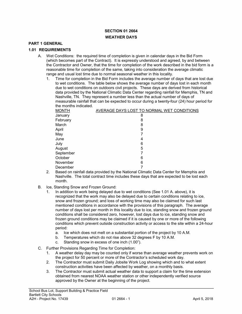
A. Wet Conditions: the required time of completion is given in calendar days in the Bid Form(which becomes part of the Contract). It is expressly understood and agreed, by and betweenthe Contractor and Owner, that the time for completion of the work described in the bid form is areasonable time for completion of the same, taking into consideration the average climaticrange and usual lost time due to normal seasonal weather in this locality.1. Time for completion in the Bid Form includes the average number of days that are lost due
to wet conditions. The table below shows the average number of days lost in each monthdue to wet conditions on outdoors civil projects. These days are derived from historicaldata provided by the National Climatic Data Center regarding rainfall for Memphis, TN andNashville, TN. They represent a number less than the actual number of days ofmeasurable rainfall that can be expected to occur during a twenty-four (24) hour period forthe months indicated.MONTH AVERAGE DAYS LOST TO NORMAL WET CONDITIONSJanuary 8February 8March 8April 9May 7June 4July 6August 5September 7October 6November 6December 7
2. Based on rainfall data provided by the National Climatic Data Center for Memphis andNashville. The total contract time includes these days that are expected to be lost eachmonth.
B. Ice, Standing Snow and Frozen Ground:1. In addition to work being delayed due to wet conditions (See 1.01 A. above), it is
recognized that the work may also be delayed due to certain conditions relating to ice,snow and frozen ground; and loss of working time may also be claimed for such lastmentioned conditions in accordance with the provisions of this paragraph. The averagenumber of days lost per month in this locality due to ice, standing snow and frozen groundconditions shall be considered zero, however, lost days due to ice, standing snow andfrozen ground conditions may be claimed if it is caused by one or more of the followingconditions which prevent outside construction activity or access to the site within a 24-hourperiod:a. Ice which does not melt on a substantial portion of the project by 10 A.M.b. Temperatures which do not rise above 32 degrees F by 10 A.M.c. Standing snow in excess of one inch (1.00”).
C. Further Provisions Regarding Time for Completion:1. A weather delay day may be counted only if worse than average weather prevents work on
the project for 50 percent or more of the Contractor’s scheduled work day.2. The Contractor must submit Daily Jobsite Work Log showing which and to what extent
construction activities have been affected by weather, on a monthly basis.3. The Contractor must submit actual weather data to support a claim for the time extension
obtained from nearest NOAA weather station or other independently verified sourceapproved by the Owner at the beginning of the project.
SECTION 01 2664 WEATHER DAYS
School Bus Lot, Support Building & Practice FieldBartlett City SchoolsA2H - Project No. 17439 01 2664 - 2 April 5, 2018
4. The Contractor must maintain a rain gauge, thermometer and clock at the job site. Keepdaily records of precipitation, temperature and the time of each occurrence throughout theproject.
5. The Contractor must organize claim and documentation to facilitate evaluation on a basisof calendar month periods, and submit monthly to the Owner.
6. If an extension of the contract time is appropriate, it shall be effected in accordance withthe provisions of the General Conditions of this contract.
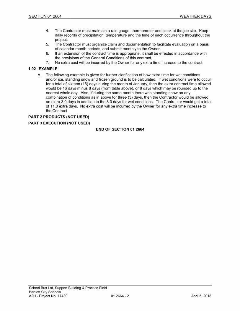
7. No extra cost will be incurred by the Owner for any extra time increase to the contract.1.02 EXAMPLE
A. The following example is given for further clarification of how extra time for wet conditionsand/or ice, standing snow and frozen ground is to be calculated. If wet conditions were to occurfor a total of sixteen (16) days during the month of January, then the extra contract time allowedwould be 16 days minus 8 days (from table above), or 8 days which may be rounded up to thenearest whole day. Also, if during the same month there was standing snow on anycombination of conditions as in above for three (3) days, then the Contractor would be allowedan extra 3.0 days in addition to the 8.0 days for wet conditions. The Contractor would get a totalof 11.0 extra days. No extra cost will be incurred by the Owner for any extra time increase tothe Contract.
PART 2 PRODUCTS (NOT USED)PART 3 EXECUTION (NOT USED)
END OF SECTION 01 2664

School Bus Lot, Support Building & Practice FieldBartlett City SchoolsA2H - Project No. 17439 01 3000 - 1 April 5, 2018
SECTION 01 3000ADMINISTRATIVE REQUIREMENTS
PART 1 GENERAL1.01 SECTION INCLUDES
A. Preconstruction meeting.B. Progress meetings.C. Construction progress schedule.D. Progress photographs.E. Coordination drawings.F. Submittals for review, information, and project closeout.G. Number of copies of submittals.H. Submittal procedures.
1.02 RELATED REQUIREMENTSA. Section 00 7200 - General Conditions: Dates for applications for payment.B. Document 00 7200 - General Conditions: Duties of the Contractor.C. Document 00 7300 - Supplementary Conditions: Duties of the Contractor.D. Section 01 6000 - Product Requirements: General product requirements.E. Section 01 7000 - Execution and Closeout Requirements: Additional coordination requirements.F. Section 01 7800 - Closeout Submittals: Project record documents; operation and maintenance
data; warranties and bonds.1.03 REFERENCE STANDARDS
A. AIA G810 - Transmittal Letter; 2001.1.04 PROJECT COORDINATION
A. Contractor is responsible for Project Coordination.B. Coordinate allocation of mobilization areas of site; for field offices and sheds, storage of
materials, for access, traffic, and parking facilities.C. Coordinate use of site and facilities during construction.D. Coordinate and comply with procedures for intra-project communications; submittals, reports
and records, schedules, coordination drawings, and recommendations; and resolution ofambiguities and conflicts.
E. Coordinate use of temporary utilities and construction facilities.F. Coordinate field engineering and layout work.G. Coordinate and make the following types of submittals to Architect/Engineer:
1. Requests for interpretation.2. Requests for substitution.3. Shop drawings, product data, and samples.4. Test and inspection reports.5. Design data.6. Manufacturer's instructions and field reports.7. Applications for payment and change order requests.8. Progress schedules.9. Coordination drawings.10. Correction Punch List and Final Correction Punch List for Substantial Completion.11. Closeout submittals.
SECTION 01 3000 ADMINISTRATIVE REQUIREMENTS
School Bus Lot, Support Building & Practice FieldBartlett City SchoolsA2H - Project No. 17439 01 3000 - 2 April 5, 2018
PART 2 PRODUCTS - NOT USEDPART 3 EXECUTION3.01 PRECONSTRUCTION MEETING
A. Owner will schedule a meeting after Notice of Award.B. Attendance Required:
1. Owner.2. Architect/Engineer.3. Contractor.4. Representatives of the major subcontractors.
C. Agenda:1. Execution of Owner-Contractor Agreement.2. Submission of executed bonds and insurance certificates.3. Distribution of Contract Documents.4. Submission of list of subcontractors, list of products, schedule of values, and progress
schedule.5. Submission of initial Submittal schedule.6. Designation of personnel representing the parties to Contract, Owner, Contractor and
Architect/Engineer.7. Procedures and processing of field decisions, submittals, substitutions, applications for
payments, proposal request, Change Orders, and Contract closeout procedures.8. Major equipment deliveries and priorities, handling of materials to permit inspection,
storage of material off-site.9. Scheduling. Sequence of critical work. Review of schedules.10. Trades whose work will require pre-start up and workmanship review meetings.11. Use of premises, access to site, field office and storage areas, security procedures and
Owner's requirements.12. Payment procedures after substantial completion.13. Additional items and subjects requested by the Owner, Contractor and Architect/Engineer.14. Scheduling activities of a Geotechnical Engineer.
D. Architect/Engineer will act as chairperson of the meeting; record minutes and distribute copieswithin two days after meeting to participants, with one copy to Architect/Engineer, Contractor,participants, and those affected by decisions made.
3.02 PROGRESS MEETINGSA. Schedule and administer meetings throughout progress of the work at maximum bi-monthly
intervals.B. Make arrangements for meetings, prepare agenda with copies for participants, preside at
meetings.C. Agenda:
1. Review minutes of previous meetings.2. Review of work progress.3. Field observations, problems, and decisions.4. Identification of problems that impede, or will impede, planned progress.5. Review of submittals schedule and status of submittals.6. Review of RFIs log and status of responses.7. Review of off-site fabrication and delivery schedules.8. Maintenance of progress schedule.9. Corrective measures to regain projected schedules.10. Planned progress during succeeding work period.11. Coordination of projected progress.12. Maintenance of quality and work standards.13. Effect of proposed changes on progress schedule and coordination.

SECTION 01 3000 ADMINISTRATIVE REQUIREMENTS
School Bus Lot, Support Building & Practice FieldBartlett City SchoolsA2H - Project No. 17439 01 3000 - 3 April 5, 2018
14. Other business relating to Work. Other current business.3.03 CONSTRUCTION PROGRESS SCHEDULE
A. Within 10 days after date of the Agreement, submit preliminary schedule defining plannedoperations for the first 60 days of work, with a general outline for remainder of work.
B. If preliminary schedule requires revision after review, submit revised schedule within 10 days.C. Within 20 days after review of preliminary schedule, submit draft of proposed complete
schedule for review.1. Include written certification that major contractors have reviewed and accepted proposed
schedule.D. Within 10 days after joint review, submit complete schedule.E. Submit updated schedule with each Application for Payment.
3.04 PROGRESS PHOTOGRAPHSA. Submit photographs with each application for payment, taken not more than 3 days prior to
submission of application for payment.B. Maintain one set of all photographs at project site for reference; same copies as submitted,
identified as such.C. Photography Type: Digital; electronic files.D. Provide photographs of site and construction throughout progress of work produced by an
experienced photographer, acceptable to Architect/Engineer.E. In addition to periodic, recurring views, take photographs of each of the following events:
1. Completion of site clearing.2. Excavations in progress.3. Foundations in progress and upon completion.4. Structural framing in progress and upon completion.5. Enclosure of building, upon completion.6. Final completion, minimum of ten (10) photos.
F. Take photographs as evidence of existing project conditions as follows:1. Interior views.2. Exterior views.
G. Views:1. Provide non-aerial photographs from four cardinal views at each specified time, until date
of Substantial Completion.2. Consult with Architect/Engineer for instructions on views required.3. Provide factual presentation.4. Provide correct exposure and focus, high resolution and sharpness, maximum depth of
field, and minimum distortion.5. Point of View Sketch: Provide sketch identifying point of view of each photograph.
H. Digital Photographs: 24 bit color, minimum resolution of 1024 by 768, in JPG format; providefiles unaltered by photo editing software.1. Delivery Medium: Via email with project record photo CD.2. File Naming: Include project identification, date and time of view, and view identification.3. Point of View Sketch: Include digital copy of point of view sketch with each electronic
submittal; include point of view identification in each photo file name.4. PDF File: Assemble all photos into printable pages in PDF format, with 2 to 3 photos per
page, each photo labeled with file name; one PDF file per submittal. 5. Photo CD(s): Provide 1 copy including all photos cumulative to date and PDF file(s), with
files organized in separate folders by submittal date.3.05 COORDINATION DRAWINGS
A. Provide information required for preparation of coordination drawings.
SECTION 01 3000 ADMINISTRATIVE REQUIREMENTS
School Bus Lot, Support Building & Practice FieldBartlett City SchoolsA2H - Project No. 17439 01 3000 - 4 April 5, 2018
B. Review drawings prior to submission to Architect/Engineer.3.06 SUBMITTAL SCHEDULE
A. Submit to Architect/Engineer for review a schedule for submittals in tabular format.1. Submit at the same time as the preliminary construction progress schedule.2. Coordinate with Contractor's construction schedule and schedule of values.3. Format schedule to allow tracking of status of submittals throughout duration of
construction.4. Arrange information to include scheduled date for initial submittal, specification number
and title, submittal category (for review or for information), description of item of workcovered, and role and name of subcontractor.
5. Account for time required for preparation, review, manufacturing, fabrication and deliverywhen establishing submittal delivery and review deadline dates.a. For assemblies, equipment, systems comprised of multiple components and/or
requiring detailed coordination with other work, allow for additional time to makecorrections or revisions to initial submittals, and time for their review.
3.07 SUBMITTALS FOR REVIEWA. When the following are specified in individual sections, submit them for review:
1. Product data.2. Shop drawings.3. Samples for selection.4. Samples for verification.5. Other types indicated.
B. Submit to Architect/Engineer for review for the limited purpose of checking for conformance withinformation given and the design concept expressed in the contract documents.
C. Samples will be reviewed for aesthetic, color, or finish selection.D. After review, provide copies and distribute in accordance with SUBMITTAL PROCEDURES
article below and for record documents purposes described in Section 01 7800 - CloseoutSubmittals.
3.08 SUBMITTALS FOR INFORMATIONA. When the following are specified in individual sections, submit them for information:
1. Design data.2. Sustainability certification related submittals and reports.3. Certificates.4. Test reports.5. Inspection reports.6. Manufacturer's instructions.7. Manufacturer's field reports.8. Other types indicated.
B. Submit for Architect/Engineer's knowledge as contract administrator or for Owner. No actionwill be taken.
3.09 SUBMITTALS FOR PROJECT CLOSEOUTA. Submit Correction Punch List for Substantial Completion.B. Submit Final Correction Punch List for Substantial Completion.C. When the following are specified in individual sections, submit them at project closeout in
conformance to requirements of Section 01 7800 - Closeout Submittals:1. Project record documents.2. Operation and maintenance data.3. Warranties.4. Bonds.5. Other types as indicated.

SECTION 01 3000 ADMINISTRATIVE REQUIREMENTS
School Bus Lot, Support Building & Practice FieldBartlett City SchoolsA2H - Project No. 17439 01 3000 - 5 April 5, 2018
D. Submit for Owner's benefit during and after project completion.3.10 NUMBER OF COPIES OF SUBMITTALS
A. Electronic Documents for Review: Submit one electronic copy in PDF format; anelectronically-marked up file will be returned. Create PDFs at native size and right-side up;illegible files will be rejected.
B. Documents for Review:1. Small Size Sheets, Not Larger Than 8-1/2 by 11 inches: Submit one copy; the Contractor
shall make his own copies from original returned by the Architect/Engineer after makinghis own file copy.
2. Larger Sheets, Not Larger Than 36 x 48 inches (910 x 1220 mm): Submit two opaquereproductions; one copy will be retained by Architect/Engineer.
C. Documents for Information: Submit one copy.D. Extra Copies at Project Closeout: See Section 01 7800.E. Samples: Submit the number specified in individual specification sections; one of which will be
retained by Architect/Engineer.1. After review, produce duplicates.2. Retained samples will not be returned to Contractor unless specifically so stated.
3.11 SUBMITTAL PROCEDURESA. General Requirements:
1. Use a separate transmittal for each item.2. Submit separate packages of submittals for review and submittals for information, when
included in the same specification section.3. Transmit using approved form.
a. Use Form AIA G810.4. Sequentially identify each item. For revised submittals use original number and a
sequential numerical suffix.5. Identify: Project; Contractor; subcontractor or supplier; pertinent drawing and detail
number; and specification section number and article/paragraph, as appropriate on eachcopy.
6. Apply Contractor's stamp, signed or initialed certifying that review, approval, verification ofproducts required, field dimensions, adjacent construction work, and coordination ofinformation is in accordance with the requirements of the work and Contract Documents.a. Submittals from sources other than the Contractor, or without Contractor's stamp will
not be acknowledged, reviewed, or returned.7. Deliver each submittal on date noted in submittal schedule, unless an earlier date has
been agreed to by all affected parties, and is of the benefit to the project.a. Deliver submittals to Architect/Engineer at business address.
8. Schedule submittals to expedite the Project, and coordinate submission of related items.a. For each submittal for review, allow 15 days excluding delivery time to and from the
Contractor.b. For sequential reviews involving Architect/Engineer's consultants, Owner, or another
affected party, allow an additional 7 days.9. Identify variations from Contract Documents and product or system limitations that may be
detrimental to successful performance of the completed work.10. Provide space for Contractor and Architect/Engineer review stamps.11. When revised for resubmission, identify all changes made since previous submission.12. Distribute reviewed submittals. Instruct parties to promptly report inability to comply with
requirements.13. Incomplete submittals will not be reviewed, unless they are partial submittals for distinct
portion(s) of the work, and have received prior approval for their use.14. Submittals not requested will not be recognized or processed.
B. Product Data Procedures:

SECTION 01 3000 ADMINISTRATIVE REQUIREMENTS
School Bus Lot, Support Building & Practice FieldBartlett City SchoolsA2H - Project No. 17439 01 3000 - 6 April 5, 2018
1. Submit only information required by individual specification sections.2. Collect required information into a single submittal.3. Do not submit (Material) Safety Data Sheets for materials or products.
C. Shop Drawing Procedures:1. Prepare accurate, drawn-to-scale, original shop drawing documentation by interpreting the
Contract Documents and coordinating related work.2. Do not reproduce the Contract Documents to create shop drawings.3. Generic, non-project-specific information submitted as shop drawings do not meet the
requirements for shop drawings.D. Samples Procedures:
1. Transmit related items together as single package.2. Identify each item to allow review for applicability in relation to shop drawings showing
installation locations.3. Include with transmittal high-resolution image files of samples to facilitate electronic review
and approval. Provide separate submittal page for each item image.END OF SECTION 01 3000
School Bus Lot, Support Building & Practice FieldBartlett City SchoolsA2H - Project No. 17439 01 4000 - 1 April 5, 2018
SECTION 01 4000QUALITY REQUIREMENTS
PART 1 GENERAL1.01 SECTION INCLUDES
A. Submittals.B. Testing and inspection agencies and services.C. Control of installation.D. Mock-ups.E. Tolerances.F. Manufacturers' field services.G. Defect Assessment.
1.02 RELATED REQUIREMENTSA. Document 00 3100 - Available Project Information: Soil investigation data.B. Document 00 7200 - General Conditions: Inspections and approvals required by public
authorities.C. Section 01 2100 - Allowances: Allowance for payment of testing services.D. Section 01 3000 - Administrative Requirements: Submittal procedures.E. Section 01 4216 - Definitions.F. Section 01 6000 - Product Requirements: Requirements for material and product quality.
1.03 REFERENCE STANDARDSA. ASTM C1021 - Standard Practice for Laboratories Engaged in Testing of Building Sealants;
2008 (Reapproved 2014).B. ASTM C1077 - Standard Practice for Laboratories Testing Concrete and Concrete Aggregates
for Use in Construction and Criteria for Laboratory Evaluation; 2014.C. ASTM C1093 - Standard Practice for Accreditation of Testing Agencies for Masonry; 2013.D. ASTM D3740 - Standard Practice for Minimum Requirements for Agencies Engaged in the
Testing and/or Inspection of Soil and Rock as Used in Engineering Design and Construction;2012a.
E. ASTM E329 - Standard Specification for Agencies Engaged in Construction Inspection and/orTesting; 2014a.
F. ASTM E543 - Standard Specification for Agencies Performing Nondestructive Testing; 2013.G. IAS AC89 - Accreditation Criteria for Testing Laboratories; 2010.
1.04 SUBMITTALSA. See Section 01 3000 - Administrative Requirements, for submittal procedures.B. Testing Agency Qualifications:
1. Prior to start of Work, submit agency name, address, and telephone number, and namesof full time registered Engineer and responsible officer.
2. Submit copy of report of laboratory facilities inspection made by NIST ConstructionMaterials Reference Laboratory during most recent inspection, with memorandum ofremedies of any deficiencies reported by the inspection.
3. Qualification Statement: Provide documentation showing testing laboratory is accreditedunder IAS AC89.
C. Design Data: Submit for Architect/Engineer's knowledge as contract administrator for thelimited purpose of assessing conformance with information given and the design conceptexpressed in the contract documents, or for Owner's information.
SECTION 01 4000 QUALITY REQUIREMENTS
School Bus Lot, Support Building & Practice FieldBartlett City SchoolsA2H - Project No. 17439 01 4000 - 2 April 5, 2018
D. Test Reports: After each test/inspection, promptly submit two copies of report toArchitect/Engineer and to Contractor.1. Include:
a. Date issued.b. Project title and number.c. Name of inspector.d. Date and time of sampling or inspection.e. Identification of product and specifications section.f. Location in the Project.g. Type of test/inspection.h. Date of test/inspection.i. Results of test/inspection.j. Conformance with Contract Documents.k. When requested by Architect/Engineer, provide interpretation of results.
2. Test report submittals are for Architect/Engineer's knowledge as contract administrator forthe limited purpose of assessing conformance with information given and the designconcept expressed in the contract documents, or for Owner's information.
E. Certificates: When specified in individual specification sections, submit certification by themanufacturer and Contractor or installation/application subcontractor to Architect/Engineer, inquantities specified for Product Data.1. Indicate material or product conforms to or exceeds specified requirements. Submit
supporting reference data, affidavits, and certifications as appropriate.2. Certificates may be recent or previous test results on material or product, but must be
acceptable to Architect/Engineer.F. Manufacturer's Instructions: When specified in individual specification sections, submit printed
instructions for delivery, storage, assembly, installation, start-up, adjusting, and finishing, for theOwner's information. Indicate special procedures, perimeter conditions requiring specialattention, and special environmental criteria required for application or installation.
G. Manufacturer's Field Reports: Submit reports for Architect/Engineer's benefit as contractadministrator or for Owner.1. Submit report in duplicate within 30 days of observation to Architect/Engineer for
information.2. Submit for information for the limited purpose of assessing conformance with information
given and the design concept expressed in the contract documents.H. Erection Drawings: Submit drawings for Architect/Engineer's benefit as contract administrator
or for Owner.1. Submit for information for the limited purpose of assessing conformance with information
given and the design concept expressed in the contract documents.2. Data indicating inappropriate or unacceptable Work may be subject to action by
Architect/Engineer or Owner.1.05 REFERENCES AND STANDARDS
A. For products and workmanship specified by reference to a document or documents not includedin the Project Manual, also referred to as reference standards, comply with requirements of thestandard, except when more rigid requirements are specified or are required by applicablecodes.
B. Conform to reference standard of date of issue current on date of Contract Documents, exceptwhere a specific date is established by applicable code.
C. Obtain copies of standards where required by product specification sections.D. Maintain copy at project site during submittals, planning, and progress of the specific work, until
Substantial Completion.E. Should specified reference standards conflict with Contract Documents, request clarification
from Architect/Engineer before proceeding.
SECTION 01 4000 QUALITY REQUIREMENTS
School Bus Lot, Support Building & Practice FieldBartlett City SchoolsA2H - Project No. 17439 01 4000 - 3 April 5, 2018
F. Neither the contractual relationships, duties, or responsibilities of the parties in Contract northose of Architect/Engineer shall be altered from the Contract Documents by mention orinference otherwise in any reference document.
1.06 TESTING AND INSPECTION AGENCIES AND SERVICESA. Contractor shall employ and pay for services of an independent testing agency to perform other
specified testing.B. Employment of agency in no way relieves Contractor of obligation to perform Work in
accordance with requirements of Contract Documents.C. Contractor Employed Agency:
1. Testing agency: Comply with requirements of ASTM E329, ASTM E543, ASTM C1021,ASTM C1077, ASTM C1093, and ASTM D3740.
2. Inspection agency: Comply with requirements of ASTM D3740 and ASTM E329.3. Laboratory Qualifications: Accredited by IAS according to IAS AC89.4. Laboratory: Authorized to operate in the State in which the Project is located.5. Laboratory Staff: Maintain a full time registered Engineer on staff to review services.6. Testing Equipment: Calibrated at reasonable intervals either by NIST or using an NIST
established Measurement Assurance Program, under a laboratory measurement qualityassurance program.
PART 2 PRODUCTS - NOT USEDPART 3 EXECUTION3.01 CONTROL OF INSTALLATION
A. Monitor quality control over suppliers, manufacturers, products, services, site conditions, andworkmanship, to produce Work of specified quality.
B. Comply with manufacturers' instructions, including each step in sequence.C. Should manufacturers' instructions conflict with Contract Documents, request clarification from
Architect/Engineer before proceeding.D. Comply with specified standards as minimum quality for the Work except where more stringent
tolerances, codes, or specified requirements indicate higher standards or more preciseworkmanship.
E. Have Work performed by persons qualified to produce required and specified quality.F. Verify that field measurements are as indicated on shop drawings or as instructed by the
manufacturer.G. Secure products in place with positive anchorage devices designed and sized to withstand
stresses, vibration, physical distortion, and disfigurement.3.02 MOCK-UPS
A. Tests shall be performed under provisions identified in this section and identified in therespective product specification sections.
B. Assemble and erect specified items with specified attachment and anchorage devices,flashings, seals, and finishes.
C. Accepted mock-ups shall be a comparison standard for the remaining Work.D. Where mock-up has been accepted by Architect/Engineer and is specified in product
specification sections to be removed, protect mock-up throughout construction, removemock-up and clear area when directed to do so by Architect/Engineer.
3.03 TOLERANCESA. Monitor fabrication and installation tolerance control of products to produce acceptable Work.
Do not permit tolerances to accumulate.B. Comply with manufacturers' tolerances. Should manufacturers' tolerances conflict with Contract
Documents, request clarification from Architect/Engineer before proceeding.

SECTION 01 4000 QUALITY REQUIREMENTS
School Bus Lot, Support Building & Practice FieldBartlett City SchoolsA2H - Project No. 17439 01 4000 - 4 April 5, 2018
C. Adjust products to appropriate dimensions; position before securing products in place.3.04 TESTING AND INSPECTION
A. See individual specification sections for testing and inspection required.B. Testing Agency Duties:
1. Test samples of mixes submitted by Contractor.2. Provide qualified personnel at site. Cooperate with Architect/Engineer and Contractor in
performance of services.3. Perform specified sampling and testing of products in accordance with specified
standards.4. Ascertain compliance of materials and mixes with requirements of Contract Documents.5. Promptly notify Architect/Engineer and Contractor of observed irregularities or
non-conformance of Work or products.6. Perform additional tests and inspections required by Architect/Engineer.7. Attend preconstruction meetings and progress meetings.8. Submit reports of all tests/inspections specified.
C. Limits on Testing/Inspection Agency Authority:1. Agency may not release, revoke, alter, or enlarge on requirements of Contract Documents.2. Agency may not approve or accept any portion of the Work.3. Agency may not assume any duties of Contractor.4. Agency has no authority to stop the Work.
D. Contractor Responsibilities:1. Deliver to agency at designated location, adequate samples of materials proposed to be
used that require testing, along with proposed mix designs.2. Cooperate with laboratory personnel, and provide access to the Work and to
manufacturers' facilities.3. Provide incidental labor and facilities:
a. To provide access to Work to be tested/inspected.b. To obtain and handle samples at the site or at source of Products to be
tested/inspected.c. To facilitate tests/inspections.d. To provide storage and curing of test samples.
4. Notify Architect/Engineer and laboratory 24 hours prior to expected time for operationsrequiring testing/inspection services.
5. Employ services of an independent qualified testing laboratory and pay for additionalsamples, tests, and inspections required by Contractor beyond specified requirements.
E. Re-testing required because of non-conformance to specified requirements shall be performedby the same agency on instructions by Architect/Engineer.
F. Re-testing required because of non-conformance to specified requirements shall be paid for byContractor.
3.05 MANUFACTURERS' FIELD SERVICESA. When specified in individual specification sections, require material or product suppliers or
manufacturers to provide qualified staff personnel to observe site conditions, conditions ofsurfaces and installation, quality of workmanship, start-up of equipment, test, adjust andbalance of equipment as applicable, and to initiate instructions when necessary.
B. Submit qualifications of observer to Architect/Engineer 30 days in advance of requiredobservations.1. Observer subject to approval of Architect/Engineer.
C. Report observations and site decisions or instructions given to applicators or installers that aresupplemental or contrary to manufacturers' written instructions.
SECTION 01 4000 QUALITY REQUIREMENTS
School Bus Lot, Support Building & Practice FieldBartlett City SchoolsA2H - Project No. 17439 01 4000 - 5 April 5, 2018
3.06 DEFECT ASSESSMENTA. Replace Work or portions of the Work not conforming to specified requirements.B. If, in the opinion of Architect/Engineer, it is not practical to remove and replace the Work,
Architect/Engineer will direct an appropriate remedy or adjust payment.END OF SECTION 01 4000
School Bus Lot, Support Building & Practice FieldBartlett City SchoolsA2H - Project No. 17439 01 4100 - 1 April 5, 2018
SECTION 01 4100REGULATORY REQUIREMENTS
PART 1 GENERAL1.01 SUMMARY OF REFERENCE STANDARDS
This list is provided as a convenience to the Contractor and is not to be considered all inclusiveof codes and regulations that may apply. The Contractor shall comply with all pertinent codes,standards, regulations and laws.Regulatory requirements applicable to this project are the following:
A. 36 CFR 1191 - Americans with Disabilities Act (ADA) Accessibility Guidelines for Buildings andFacilities; Architectural Barriers Act (ABA) Accessibility Guidelines; current edition.
B. ADA Standards - Americans with Disabilities Act (ADA) Standards for Accessible Design; 2010.C. 29 CFR 1910 - Occupational Safety and Health Standards; current edition.D. State of Tennessee amendments to some or all of the following.E. City of Bartlett amendments to some or all of the following.F. Zoning Code: RS - 15.G. ICC (IBC) - International Building Code; 2012.H. ICC (IFC) - International Fire Code; 2009.I. NFPA 101 - Life Safety Code; 2012.J. ICC (IPC) - International Plumbing Code; 2009.K. ICC (IMC) - International Mechanical Code; 2009.L. ICC (IFGC) - International Fuel Gas Code; 2009.M. ICC (IECC) - International Energy Conservation Code; 2009.N. NFPA 5000 - Building Construction and Safety Code; 2012.O. NFPA 70 - National Electrical Code; Most Recent Edition Adopted by Authority Having
Jurisdiction, Including All Applicable Amendments and Supplements.P. Erosion and Sedimentation Control Regulations: TDEC.
1.02 RELATED REQUIREMENTSA. Section 01 4000 - Quality Requirements.
1.03 QUALITY ASSURANCEA. Designer Qualifications: Where delegated engineering design is to be performed under the
construction contract provide the direct supervision of a Professional Engineer experienced indesign of this type of work and licensed in the State in which the Project is located.
PART 2 PRODUCTS - NOT USEDPART 3 EXECUTION - NOT USED
END OF SECTION 01 4100

School Bus Lot, Support Building & Practice FieldBartlett City SchoolsA2H - Project No. 17439 01 4216 - 1 April 5, 2018
SECTION 01 4216DEFINITIONS
PART 1 GENERAL1.01 SUMMARY
A. General Explanation: A substantial amount of specification language constitutes definitions forterms found in other contract documents, including the drawings which must be recognized asdiagrammatic in nature and not completely descriptive of requirements indicated thereon. Certain terms used in the contract documents are defined generally in this article. Definitionsand explanations of this section are not necessarily either complete or exclusive, but aregeneral for the work to extents not stated more explicitly in another provisions of the contractdocuments. This section supplements the definitions contained in the General Conditions.
B. General Requirements: The provisions or requirements of Division 01 sections. Generalrequirements apply to either work of contract and, where so indicated, to other elements of workwhich are included in the project. Other definitions are included in individual specificationsections.
C. Other definitions are included in individual specification sections.1.02 DEFINITIONS
A. Indicated: The term “Indicated” is a cross-reference to details, notes or schedules on thedrawings, to other paragraphs or schedules in the Project Manual, and to similar means ofrecording requirements in the contract documents. Where terms such as “shown”, “noted”,“scheduled”, and “specified” are used in lieu of “indicated”, it is for the purpose of helping thereader locate cross-reference, and no limitation of location is intended except as specificallynoted.
B. Directed, Requested, etc.: Where not otherwise explained, terms such as “directed”,“requested”, “authorized”, “selected”, “approved”, “required”, “accepted” and “permitted” mean“directed by Architect/Engineer”, “requested by Architect/Engineer”, etc. However, no suchimplied meaning will be interpreted to extend Architect/Engineer’s responsibility into Contractor’sarea of construction supervision.
C. Approved: Where used in conjunction with Architect/Engineer’s response to submittals,requests, applications, inquiries, reports and claims by Contractor, the meaning of term“approved” will be held to limitations of Architect/Engineer’s responsibility and duties asspecified in general and Supplementary Conditions. In no case will “approval” byArchitect/Engineer be interpreted as a release of Contractor from responsibilities to fulfillrequirements of the contract documents.
D. Project Site: The space available to Contractor for performance of the work, either exclusively orin conjunction with others performing other work as part of the project. The extent of project siteis shown on the drawings, and may or may not be identical with description of the land uponwhich project is to be built.
E. Furnish: To supply and deliver to project site, ready for unloading, unpacking, inspect fordamage, assembly, installation, etc., as applicable in each instance.
F. Install: Operations at project site including unloading, unpacking, assembly, erection, placing,anchoring, applying, working to dimension, finishing, curing, protection, cleaning, start up andsimilar operations, make ready for use, as applicable in each instance.
G. Provide: Except as otherwise defined in greater detail, term “provide” means furnish and install,complete and ready for intended use, as applicable in each instance.
H. Installer: The entity (person or firm) engaged by the Contractor or its subcontractor or subsubcontractor for the performance of a particular unit of work at the project site, includinginstallation, erection, application, and similar required operations. It is a general requirementthat such entities (installers) be expert in operations they are engaged to perform.

SECTION 01 4216 DEFINITIONS
School Bus Lot, Support Building & Practice FieldBartlett City SchoolsA2H - Project No. 17439 01 4216 - 2 April 5, 2018
I. Testing Laboratory: An independent entity engaged to perform specific inspections or tests ofthe work, at project site and to report and (if required) interpret results of those inspections ortests. Refer to Section 01 4000.
J. Product: Material, machinery, components, equipment, fixtures, and systems forming the workresult. Not materials or equipment used for preparation, fabrication, conveying, or erection andnot incorporated into the work result. Products may be new, never before used, or re-usedmaterials or equipment.
K. Project Manual: The book-sized volume that includes the procurement requirements (if any),the contracting requirements, and the specifications.
1.03 FORMAT AND SPECIFICATION EXPLANATIONSA. Specification Production: None of these explanations will be interpreted to modify substance of
requirements. Portions of these specifications have been produced by Architect’s standardmethods of editing master specifications, and may contain minor deviations from traditionalwriting formats. Such deviations are a normal result of this production technique, and no othermeaning will be implied or permitted.
B. Format Explanation: The format of principal portions of these specifications can be described asfollows; although other portions may not fully comply and no particular significance will beattached to such compliance or non-compliance:1. Sections and Divisions: For convenience, basic unit of specification text is a “section”,
each unit of which is named and numbered. These are organized into related families ofsections, and various families of sections are organized into “divisions”, which arerecognized as the present industry - consensus on uniform organization and sequencing ofspecifications. The section title is not intended to limit meaning or content of section, norto be fully descriptive of requirements specified therein, nor to be an integral part of text.a. Each section of specifications has been subdivided into 3 (or less), “parts” for
uniformity and convenience (Part 1 - General, Part 2 - Products, and Part 3 -Execution). These do not limit the meaning and are not an integral part of text whichspecifies requirements.
C. Imperative Language: Used generally in specifications. Except as otherwise indicated,requirements expressed imperatively are to be performed by Contractor. For clarity of readingat certain locations, contrasting subjective language is used to describe responsibilities whichmust be fulfilled indirectly by Contractor, or when so noted, by others.
D. Section Numbering: Used to facilitate cross-references in contract documents. Sections areplaced in Project Manual in numeric sequence; however, numbering sequence is not complete,and listing of sections at beginning of Project Manual must be consulted to determine numbersand names of specification sections in the contract documents.
E. Page Numbering: Numbered independently for each section; recorded in listing of section(Index or Table of Contents) in Project Manual. Section number is shown with page number atbottom of each page, to facilitate location of text in Project Manual.
F. Specification Content: Because of methods by which this project specification has beenproduced, certain general characteristics of content, and conventions in use of language areexplained as follows:1. Specifying Methods: The techniques or methods of specifying to record requirements
varies throughout text, and may include “prescriptive”, “open generic - descriptive”,“compliance with standards”, “performance”, “proprietary” or a combination of these. Themethod used for specifying one unit of work has no bearing on requirements for anotherunit of work.
2. Overlapping and Conflicting Requirements: Where compliance with 2 or more industrystandards or sets of requirements is specified, and overlapping of those differentstandards or requirements establishes different or conflicting minimum or levels of quality,the most stringent requirement (which is generally recognized to be most costly) isintended and will be enforced, unless specifically detailed language written into thecontract documents (not by way of reference to an industry standard) clearly indicates that

SECTION 01 4216 DEFINITIONS
School Bus Lot, Support Building & Practice FieldBartlett City SchoolsA2H - Project No. 17439 01 4216 - 3 April 5, 2018
a less stringent requirement is to be fulfilled. Refer apparently-equal-but-differentrequirements and uncertainties as to which level of quality is more stringent to Architect fordecision before proceeding.a. Contractor’s Options: Except for overlapping or conflicting requirements, where more
than one set of requirements are specified for a particular unit of work, option isintended to be contractor’s regardless of whether specifically indicated as such.
3. Minimum Quality/Quantity: In every instance, quality level or quantity shown or specified isintended as minimum for the work to be performed or provided. Except as otherwisespecifically indicated, actual work may either comply exactly with that minimum withinspecified tolerances, or may exceed that minimum within reasonable limits. In complyingwith requirements, indicated numeric values are either minimums or maximums as notedor as appropriate for context of requirements. Refer instances of uncertainty to Architectfor decision before proceeding.
4. Specialist’s Assignments: In certain instances, specification text requires (or at leastimplies) that specific work be assigned to specialists or expert entities, who must beengaged for performance of those units of work. These must be recognized as specialrequirements over which Contractor has no choice or option. These assignments must notbe confused with (and are not intended to interfere with) normal application of regulations,union jurisdictions and similar conventions. One purpose of such assignments is toestablish which party or entity involved in a specific unit of work is recognized as “expert”for indicated construction processes or operations. Nevertheless, final responsibility forfulfillment of entire set of requirements remains with Contractor.
5. Trades: Except as otherwise indicated, the use of titles (such as “carpentry”) inspecification text, implies neither that the work must be performed by an accredited orunionized tradesman of the corresponding generic name (such as “carpenter”), nor thatspecified requirements apply exclusively to work by tradesman of the correspondinggeneric name.
6. Abbreviations: The language of specifications and other contract documents is of theabbreviated type in certain instances, and implies words and meanings which will beappropriately interpreted. Actual work abbreviations of a self-explanatory nature havebeen included in the text. Specific abbreviations have been established, principally forlengthy technical terminology and primarily in conjunction with coordination of specificationrequirements with notations on drawings and in schedules.a. These are frequently defined in sections at first instance of use. Trade association
names and titles of general standards are frequently abbreviated. Singular words willbe interpreted as plural and plural words will be interpreted as singular whereapplicable and where full context of the contract documents so indicate.
1.04 DRAWING SYMBOLSA. General: Except as otherwise indicated, graphic symbols used on drawings are those symbols
recognized in the construction industry for purposes indicated. Where not otherwise noted,symbols are defined by “Architectural Graphic Standards”, published by John Wiley & Sons,Inc., latest edition.
1.05 INDUSTRY STANDARDSA. General Applicability of Standards: Applicable standards of construction industry have same
force and effect (and are made a part of contract documents by reference) as if copied directlyinto contract documents, or as if published copies were bound herewith.1. Referenced standards (referenced directly in contract documents or by governing
regulations) have precedence over non-referenced standards which are recognized inindustry for applicability to work.
2. Non-referenced standards recognized in the construction industry are hereby defined,except as otherwise limited in contract documents, to have direct applicability to the work,and will be so enforced for performance of the work.
B. Publication Dates: Except as otherwise indicated, where compliance with an industry standard isrequired, comply with standard in effect as of date in contract documents.

SECTION 01 4216 DEFINITIONS
School Bus Lot, Support Building & Practice FieldBartlett City SchoolsA2H - Project No. 17439 01 4216 - 4 April 5, 2018
C. Copies of Standards: Provide where needed for proper performance of the work; obtain directlyfrom publication sources.
D. Abbreviations and Names: Where acronyms or abbreviations are used in specifications or othercontract documents they are defined to mean the industry recognized name and tradeassociation, standards generating organization, governing authority or other “Encyclopedia ofAssociations”, published by Gale Research Co., available in large libraries.
1.06 GOVERNING REGULATIONS/AUTHORITIESA. General: The procedure followed by the Architect has been to contact governing authorities
where necessary to obtain information needed for the purpose of preparing the contractdocuments; recognizing that such information may or may not be of significance in relation tothe Contractor’s responsibilities for performing the work. Contact governing authorities directlyfor necessary information and decisions having a bearing on the performance of the work.
1.07 SUBMITTALA. Permits, Licenses and Certificates: For the Owner’s records, submit copies of permits, licenses,
certifications, inspection reports, releases, jurisdictional settlements, notices, receipts for feepayments, judgments, and similar documents, correspondence and records established inconjunction with compliance with standards and regulations bearing upon performance of thework.
PART 2 PRODUCTS - NOT USEDPART 3 EXECUTION - NOT USED
END OF SECTION 01 4216
School Bus Lot, Support Building & Practice FieldBartlett City SchoolsA2H - Project No. 17439 01 5000 - 1 April 5, 2018
SECTION 01 5000TEMPORARY FACILITIES AND CONTROLS
PART 1 GENERAL1.01 SECTION INCLUDES
A. Temporary utilities.B. Temporary telecommunications services.C. Temporary sanitary facilities.D. Temporary Controls: Barriers, enclosures, and fencing.E. Security requirements.F. Vehicular access and parking.G. Waste removal facilities and services.H. Project identification sign.I. Field offices.
1.02 RELATED REQUIREMENTSA. Section 01 7000 - Execution and Closeout Requirements: Cleaning.
1.03 TEMPORARY UTILITIESA. Owner will provide the following:
1. Electrical power and metering, consisting of connection to existing facilities.2. Water supply, consisting of connection to existing facilities.
B. Provide and pay for all electrical power, lighting, water, heating and cooling, and ventilationrequired for construction purposes.
C. Existing facilities may not be used.D. New permanent facilities may not be used.E. Use trigger-operated nozzles for water hoses, to avoid waste of water.
1.04 TELECOMMUNICATIONS SERVICESA. Provide, maintain, and pay for telecommunications services to field office at time of project
mobilization.B. Telecommunications services shall include:
1. Windows-based personal computer dedicated to project telecommunications, withnecessary software and laser printer.
2. Internet Connections: Minimum of one; DSL modem or faster.3. Email: Account/address reserved for project use.
C. Architect/Engineer will pay for own telecommunications services.1.05 TEMPORARY SANITARY FACILITIES
A. Provide and maintain required facilities and enclosures. Provide at time of project mobilization.B. Use of existing facilities is not permitted.C. New permanent facilities may not be used during construction operations.D. Maintain daily in clean and sanitary condition.E. At end of construction, return facilities to same or better condition as originally found.
1.06 BARRIERSA. Provide barriers to prevent unauthorized entry to construction areas, to prevent access to areas
that could be hazardous to workers or the public, to allow for owner's use of site and to protectexisting facilities and adjacent properties from damage from construction operations anddemolition.

SECTION 01 5000 TEMPORARY FACILITIES AND CONTROLS
School Bus Lot, Support Building & Practice FieldBartlett City SchoolsA2H - Project No. 17439 01 5000 - 2 April 5, 2018
B. Provide barricades and covered walkways required by governing authorities for publicrights-of-way and for public access to existing building.
C. Provide protection for plants designated to remain. Replace damaged plants.D. Protect non-owned vehicular traffic, stored materials, site, and structures from damage.
1.07 FENCINGA. Construction: Commercial grade chain link fence.B. Provide 6 foot high fence around construction site; equip with vehicular and pedestrian gates
with locks.1.08 EXTERIOR ENCLOSURES
A. Provide temporary insulated weather tight closure of exterior openings to accommodateacceptable working conditions and protection for Products, to allow for temporary heating andmaintenance of required ambient temperatures identified in individual specification sections,and to prevent entry of unauthorized persons. Provide access doors with self-closing hardwareand locks.
1.09 SECURITY A. Provide security and facilities to protect Work, existing facilities, and Owner's operations from
unauthorized entry, vandalism, or theft.B. Coordinate with Owner's security program.
1.10 VEHICULAR ACCESS AND PARKINGA. Comply with regulations relating to use of streets and sidewalks, access to emergency facilities,
and access for emergency vehicles.B. Coordinate access and haul routes with governing authorities and Owner.C. Provide and maintain access to fire hydrants, free of obstructions.D. Provide means of removing mud from vehicle wheels before entering streets.E. Designated existing on-site roads may be used for construction traffic.F. Provide temporary parking areas to accommodate construction personnel. When site space is
not adequate, provide additional off-site parking.G. Do not allow vehicle parking on existing pavement.H. Provide one parking space for Owner use.I. Provide one parking space for Architect/Engineer use.
1.11 WASTE REMOVALA. Provide waste removal facilities and services as required to maintain the site in clean and
orderly condition.B. Provide containers with lids. Remove trash from site weekly.C. If materials to be recycled or re-used on the project must be stored on-site, provide suitable
non-combustible containers; locate containers holding flammable material outside the structureunless otherwise approved by the authorities having jurisdiction.
D. Open free-fall chutes are not permitted. Terminate closed chutes into appropriate containerswith lids.
1.12 PROJECT IDENTIFICATIONA. Provide project identification sign of design and construction indicated on Drawings.B. Erect on site at location indicated.C. No other signs are allowed without Owner permission except those required by law.

SECTION 01 5000 TEMPORARY FACILITIES AND CONTROLS
School Bus Lot, Support Building & Practice FieldBartlett City SchoolsA2H - Project No. 17439 01 5000 - 3 April 5, 2018
1.13 FIELD OFFICESA. Office: Weathertight, with lighting, electrical outlets, heating, cooling equipment, and equipped
with sturdy furniture, drawing rack, and drawing display table.B. Provide space for Project meetings, with table and chairs to accommodate 10 persons.C. Provide separate work station similarly equipped and furnished, for use of Architect/Engineer
and Owner.D. Locate offices a minimum distance of 30 feet from existing and new structures.
1.14 REMOVAL OF UTILITIES, FACILITIES, AND CONTROLSA. Remove temporary utilities, equipment, facilities, materials, prior to Date of Substantial
Completion inspection.B. Remove underground installations to a minimum depth of 2 feet. Grade site as indicated.C. Clean and repair damage caused by installation or use of temporary work.D. Restore existing facilities used during construction to original condition.E. Restore new permanent facilities used during construction to specified condition.
PART 2 PRODUCTS - NOT USEDPART 3 EXECUTION - NOT USED
END OF SECTION 01 5000

School Bus Lot, Support Building & Practice FieldBartlett City SchoolsA2H - Project No. 17439 01 5713 - 1 April 5, 2018
SECTION 01 5713TEMPORARY EROSION AND SEDIMENT CONTROL
PART 1 GENERAL1.01 SECTION INCLUDES
A. Prevention of erosion due to construction activities.B. Prevention of sedimentation of waterways, open drainage ways, and storm and sanitary sewers
due to construction activities.C. Restoration of areas eroded due to insufficient preventive measures.D. Performance bond.E. Compensation of Owner for fines levied by authorities having jurisdiction due to non-compliance
by Contractor.1.02 RELATED REQUIREMENTS
A. Section 03 3000 - Cast-in-Place Concrete: Concrete for temporary and permanent erosioncontrol structures indicated on drawings.
B. Section 31 1000 - Site Clearing: Limits on clearing; disposition of vegetative clearing debris.C. Section 31 2200 - Grading: Temporary and permanent grade changes for erosion control.D. Section 31 3700 - Riprap: Temporary and permanent stabilization using riprap.E. Section 32 9223 - Sodding: Permanent turf for erosion control.F. Section 32 9300 - Plants: Permanent plantings for erosion control.
1.03 REFERENCE STANDARDSA. ASTM D4355/D4355M - Standard Test Method for Deterioration of Geotextiles by Exposure to
Light, Moisture and Heat in a Xenon Arc Type Apparatus; 2014.B. ASTM D4491 - Standard Test Methods for Water Permeability of Geotextiles by Permittivity;
1999a (Reapproved 2014).C. ASTM D4533 - Standard Test Method for Trapezoid Tearing Strength of Geotextiles; 2011.D. ASTM D4632/D4632M - Standard Test Method for Grab Breaking Load and Elongation of
Geotextiles; 2015a.E. ASTM D4751 - Standard Test Method for Determining Apparent Opening Size of a Geotextile;
2012.F. ASTM D4873 - Standard Guide for Identification, Storage, and Handling of Geosynthetic Rolls
and Samples; 2002 (Reapproved 2009).G. EPA (NPDES) - National Pollutant Discharge Elimination System (NPDES), Construction
General Permit; Current Edition.H. USDA TR-55 - Urban Hydrology for Small Watersheds; USDA Natural Resources Conservation
Service; 2009.1.04 PERFORMANCE REQUIREMENTS
A. Comply with requirements of EPA (NPDES) for erosion and sedimentation control, as specifiedby the NPDES, for Phases I and II, and in compliance with requirements of ConstructionGeneral Permit (CGP), whether the project is required by law to comply or not.
B. Also comply with all more stringent requirements of State of Tennessee Erosion andSedimentation Control Manual.
C. Runoff Calculation Standard for Urban Areas: USDA TR-55.D. Develop and follow an Erosion and Sedimentation Prevention Plan and submit periodic
inspection reports.

SECTION 01 5713 TEMPORARY EROSION AND SEDIMENT CONTROL
School Bus Lot, Support Building & Practice FieldBartlett City SchoolsA2H - Project No. 17439 01 5713 - 2 April 5, 2018
E. Do not begin clearing, grading, or other work involving disturbance of ground surface cover untilapplicable permits have been obtained; furnish all documentation required to obtain applicablepermits.1. Owner will obtain permits and pay for securities required by authority having jurisdiction.2. Obtain and pay for permits and provide security required by authority having jurisdiction.3. Owner will withhold payment to Contractor equivalent to all fines resulting from
non-compliance with applicable regulations.F. Provide to Owner a Performance Bond covering erosion and sedimentation preventive
measures only, in an amount equal to 100 percent of the cost of erosion and sedimentationcontrol work.
G. Timing: Put preventive measures in place as soon as possible after disturbance of surfacecover and before precipitation occurs.
H. Storm Water Runoff: Control increased storm water runoff due to disturbance of surface coverdue to construction activities for this project.1. Prevent runoff into storm and sanitary sewer systems, including open drainage channels,
in excess of actual capacity or amount allowed by authorities having jurisdiction, whicheveris less.
2. Anticipate runoff volume due to the most extreme short term and 24-hour rainfall eventsthat might occur in 25 years.
I. Erosion On Site: Minimize wind, water, and vehicular erosion of soil on project site due toconstruction activities for this project.1. Control movement of sediment and soil from temporary stockpiles of soil.2. Prevent development of ruts due to equipment and vehicular traffic.3. If erosion occurs due to non-compliance with these requirements, restore eroded areas at
no cost to Owner.J. Erosion Off Site: Prevent erosion of soil and deposition of sediment on other properties caused
by water leaving the project site due to construction activities for this project.1. Prevent windblown soil from leaving the project site.2. Prevent tracking of mud onto public roads outside site.3. Prevent mud and sediment from flowing onto sidewalks and pavements.4. If erosion occurs due to non-compliance with these requirements, restore eroded areas at
no cost to Owner.K. Sedimentation of Waterways On Site: Prevent sedimentation of waterways on the project site,
including rivers, streams, lakes, ponds, open drainage ways, storm sewers, and sanitarysewers.1. If sedimentation occurs, install or correct preventive measures immediately at no cost to
Owner; remove deposited sediments; comply with requirements of authorities havingjurisdiction.
2. If sediment basins are used as temporary preventive measures, pump dry and removedeposited sediment after each storm.
L. Sedimentation of Waterways Off Site: Prevent sedimentation of waterways off the project site,including rivers, streams, lakes, ponds, open drainage ways, storm sewers, and sanitarysewers.1. If sedimentation occurs, install or correct preventive measures immediately at no cost to
Owner; remove deposited sediments; comply with requirements of authorities havingjurisdiction.
M. Open Water: Prevent standing water that could become stagnant.N. Maintenance: Maintain temporary preventive measures until permanent measures have been
established.1.05 SUBMITTALS
A. See Section 01 3000 - Administrative Requirements, for submittal procedures.

SECTION 01 5713 TEMPORARY EROSION AND SEDIMENT CONTROL
School Bus Lot, Support Building & Practice FieldBartlett City SchoolsA2H - Project No. 17439 01 5713 - 3 April 5, 2018
B. Erosion and Sedimentation Control Plan:1. Submit within 2 weeks after Notice to Proceed.2. Submit not less than 30 days prior to anticipated start of clearing, grading, or other work
involving disturbance of ground surface cover.3. Include:
a. Site plan identifying soils and vegetation, existing erosion problems, and areasvulnerable to erosion due to topography, soils, vegetation, or drainage.
b. Measurements of existing turbidity of waterways.c. Site plan showing grading; new improvements; temporary roads, traffic accesses, and
other temporary construction; and proposed preventive measures.d. Where extensive areas of soil will be disturbed, include storm water flow and volume
calculations, soil loss predictions, and proposed preventive measures.e. Schedule of temporary preventive measures, in relation to ground disturbing activities.f. Other information required by law.g. Format required by law is acceptable, provided any additional information specified is
also included.4. Obtain the approval of the Plan by authorities having jurisdiction.5. Obtain the approval of the Plan by Owner.
C. Certificate: Mill certificate for silt fence fabric attesting that fabric and factory seams comply withspecified requirements, signed by legally authorized official of manufacturer; indicate actualminimum average roll values; identify fabric by roll identification numbers.
D. Inspection Reports: Submit report of each inspection; identify each preventive measure,indicate condition, and specify maintenance or repair required and accomplished.
E. Maintenance Instructions: Provide instructions covering inspection and maintenance fortemporary measures that must remain after Substantial Completion.
PART 2 PRODUCTS2.01 MATERIALS
A. Mulch: Use one of the following:1. Straw or hay.2. Wood waste, chips, or bark.3. Erosion control matting or netting.4. Cutback asphalt.5. Polyethylene film, where specifically indicated only.
B. Grass Seed For Temporary Cover: Select a species appropriate to climate, planting season,and intended purpose. If same area will later be planted with permanent vegetation, do not usespecies known to be excessively competitive or prone to volunteer in subsequent seasons.
C. Bales: Air dry, rectangular straw bales.1. Cross Section: 14 by 18 inches, minimum.2. Bindings: Wire or string, around long dimension.
D. Bale Stakes: One of the following, minimum 3 feet long:1. Steel U- or T-section, with minimum mass of 1.33 lb per linear foot.2. Wood, 2 by 2 inches in cross section.
E. Silt Fence Fabric: Polypropylene geotextile resistant to common soil chemicals, mildew, andinsects; non-biodegradable; in longest lengths possible; fabric including seams with thefollowing minimum average roll lengths:1. Average Opening Size: 30 U.S. Std. Sieve, maximum, when tested in accordance with
ASTM D4751.2. Permittivity: 0.05 sec^-1, minimum, when tested in accordance with ASTM D4491.3. Ultraviolet Resistance: Retaining at least 70 percent of tensile strength, when tested in
accordance with ASTM D4355/D4355M after 500 hours exposure.

SECTION 01 5713 TEMPORARY EROSION AND SEDIMENT CONTROL
School Bus Lot, Support Building & Practice FieldBartlett City SchoolsA2H - Project No. 17439 01 5713 - 4 April 5, 2018
4. Tensile Strength: 100 lb-f, minimum, in cross-machine direction; 124 lb-f, minimum, inmachine direction; when tested in accordance with ASTM D4632/D4632M.
5. Elongation: 15 to 30 percent, when tested in accordance with ASTM D4632/D4632M.6. Tear Strength: 55 lb-f, minimum, when tested in accordance with ASTM D4533.7. Color: Manufacturer's standard, with embedment and fastener lines preprinted.8. Manufacturers:
a. TenCate: www.tencate.com.b. North American Green: www.nagreen.com. c. Propex Geosynthetics: www.geotextile.comd. Substitutions: See Section 01 6000 - Product Requirements.
F. Silt Fence Posts: One of the following, minimum 5 feet long:1. Steel U- or T-section, with minimum mass of 1.33 lb per linear foot.2. Softwood, 4 by 4 inches in cross section.3. Hardwood, 2 by 2 inches in cross section.
G. Gravel: See Section 32 1123 for aggregate.H. Riprap: See Section 31 3700.I. Concrete: See Section 03 3000.
PART 3 EXECUTION3.01 EXAMINATION
A. Prior to the pre-construction conference, the Contractor shall meet with the Architect/Engineerand go over in detail the expected problem areas in regard to the erosion control work. Different solutions should be discussed so that the best method might be determined. It is theresponsibility of the Contractor to develop an erosion control plan acceptable to theArchitect/Engineer.
B. Examine site and identify existing features that contribute to erosion resistance; maintain suchexisting features to greatest extent possible.
3.02 PREPARATIONA. At the pre-construction conference, the Contractor shall submit for acceptance his schedule for
accomplishment of temporary and permanent erosion control work, as is applicable for clearingand grubbing, grading, bridges and other structures at watercourses, construction and paving. He shall also submit for acceptance his proposed method for erosion control on haul roads andborrow pits and his plan for disposal of waste materials. No work shall be started until theerosion control schedules and methods of operations have been accepted by the Engineer.
B. Schedule work so that soil surfaces are left exposed for the minimum amount of time.3.03 SCOPE OF PREVENTIVE MEASURES
A. This section shall consist of temporary control measures as shown in the Plans or directed bythe Engineer during the life of the Contract to control erosion and pollution through the use ofberms, dikes, dams, sediment basins, fiber mats, netting, mulches, grasses, slope drains,temporary silt fences, and other control devices.
B. The temporary pollution control provisions contained herein shall be coordinated with thepermanent erosion control features to assure economical, effective, and continuous erosionfeatures and to assure economical, effective, and continuous erosion control throughout theconstruction and post-construction period.
C. The Engineer has the authority to limit the surface area of erodible earth material exposed byclearing and grubbing, the surface of erodible earth material exposed by excavation, borrow andfill operations and to direct the Contractor to provide immediate permanent or temporarypollution control measures to prevent contamination of adjacent streams or other watercourses,lakes, ponds, or other water impoundment. Such work may involve the construction oftemporary berms, dikes, dams, sediment basins, slope drains and use of temporary mulches,

SECTION 01 5713 TEMPORARY EROSION AND SEDIMENT CONTROL
School Bus Lot, Support Building & Practice FieldBartlett City SchoolsA2H - Project No. 17439 01 5713 - 5 April 5, 2018
mats, seeding or other control devices or methods to control erosion. Cut and fill slopes shall beseeded and mulched as the excavation proceeds to the extent directed by the Engineer.
D. The Contractor shall be required to incorporate all permanent erosion control features into theproject at the earliest practicable time as outlined in his accepted schedule. Temporarypollution control measures shall be used to correct conditions that develop during constructionthat were not foreseen during the design stage; that are needed prior to installation ofpermanent pollution control features; or that are needed temporarily to control erosion thatdevelops during normal construction practices, but are not associated with permanent controlfeatures on the project.
E. Where erosion is likely to be a problem, clearing and grubbing operations should be soscheduled and performed that grading operations and permanent erosion control features canfollow immediately thereafter if the project conditions permit; otherwise erosion controlmeasures may be required between successive construction stages. Under no conditions shallthe surface area of erodible earth material exposed at one time by clearing and grubbingexceed 750,000 square feet without approval of the Engineer.
F. The Engineer will limit the area of excavation, borrow and embankment operations in progresscommensurate with the Contractor's capability and progress in keeping the finish grading,mulching, seeding, and other such permanent pollution control measures current in accordancewith the accepted schedule. Should seasonal limitations make such coordination unrealistic,temporary erosion control measures shall be taken immediately to the extent feasible andjustified.
G. Under no conditions shall the amount of surface area or erodible earth material exposed at onetime by excavation or fill within the project area exceed 750,000 square feet without priorapproval by the Engineer.
H. The Engineer may increase or decrease the amount of surface area of erodible earth materialto be exposed at one time by clearing and grubbing, excavation, borrow, and fill operations asdetermined by his analysis of project conditions.
I. In the event of conflict between these requirements and pollution control laws, rules orregulations, or other Federal, State, or Local agencies, the more restrictive laws, rules andregulations shall apply.
J. In all cases, if permanent erosion resistant measures have been installed temporary preventivemeasures are not required.
K. Temporary Berms: A temporary berm is constructed of compacted soil, with or without ashallow ditch at the top of fill slopes or transverse to centerline on fills.
L. Temporary Slope Drains: A temporary slope drain is a facility consisting of stone gutters, fibermats, plastic sheets, concrete or asphalt gutters, half-round pipe, metal pipe, plastic pipe, sodor other material acceptable to the Engineer that may be used to carry water down slopes toreduce erosion.
M. Sediment Structures: Sediment basins, ponds and traps are prepared storage areasconstructed to trap and store sediment from erodible areas in order to protect properties andstream channels below the constructed areas from excessive siltation.
N. Check Dams: Check dams are barriers composed of logs and poles, large stones or othermaterials placed across a natural or constructed drainway. Stone check dams shall not beutilized where the drainage area exceeds fifty (50) acres. Log and pole structures shall not beused where the drainage area exceeds five (5) acres.
O. Temporary Seeding and Mulching: Temporary seeding and mulching are measures consistingof seeding, mulching, fertilizing and mating utilized to reduce erosion. All cut and fill slopesincluding waste sites and borrow pits shall be seeded when and where necessary to eliminateerosion.
P. Brush Barriers: Brush barriers shall consist of brush, tree trimmings, shrubs, plants, and otherapproved refuse from the clearing and grubbing operations. Brush barriers are placed on

SECTION 01 5713 TEMPORARY EROSION AND SEDIMENT CONTROL
School Bus Lot, Support Building & Practice FieldBartlett City SchoolsA2H - Project No. 17439 01 5713 - 6 April 5, 2018
natural ground at the bottom of fill slopes, where the most likely erodible areas are located torestrain sedimentation particles.
Q. Baled Hay or Straw Checks: Baled hay or straw erosion checks are temporary measures tocontrol erosion and prevent siltation. Bales shall be either hay or straw containing five (5) cubicfeet or more of material. Baled hay or straw checks shall be used where the existing groundslopes toward or away from the embankment along the toe of the slopes, in ditches or otherareas where siltation erosion or water run-off is a problem.
R. Temporary Silt Fences: Silt fences are temporary measures utilizing woven wire or otherapproved material attached to post with filter cloth composed of burlap, plastic filter fabric, etc.,attached to the upstream side of the fence to retain the suspended silt particles in the run-offwater.
S. Construction Entrances: Traffic-bearing aggregate surface.1. Width: As required; 20 feet, minimum.2. Length: 50 feet, minimum.3. Provide at each construction entrance from public right-of-way.4. Where necessary to prevent tracking of mud onto right-of-way, provide wheel washing
area out of direct traffic lane, with drain into sediment trap or basin.T. Linear Sediment Barriers: Made of silt fences.
1. Provide linear sediment barriers:a. Along downhill perimeter edge of disturbed areas, including soil stockpiles.b. Along the top of the slope or top bank of drainage channels and swales that traverse
disturbed areas.c. Along the toe of cut slopes and fill slopes.d. Perpendicular to flow across the bottom of existing and new drainage channels and
swales that traverse disturbed areas or carry runoff from disturbed areas; space atmaximum of 200 feet apart.
e. Across the entrances to culverts that receive runoff from disturbed areas.2. Space sediment barriers with the following maximum slope length upslope from barrier:
a. Slope of Less Than 2 Percent: 100 feet..b. Slope Between 2 and 5 Percent: 75 feet.c. Slope Between 5 and 10 Percent: 50 feet.d. Slope Between 10 and 20 Percent: 25 feet.e. Slope Over 20 Percent: 15 feet.
U. Storm Drain Curb Inlet Sediment Trap: Protect each curb inlet using one of the followingmeasures:1. Filter fabric wrapped around hollow concrete blocks blocking entire inlet face area; use one
piece of fabric wrapped at least 1-1/2 times around concrete blocks and secured toprevent dislodging; orient cores of blocks so runoff passes into inlet.
2. Straw bale row blocking entire inlet face area; anchor into pavement.V. Storm Drain Drop Inlet Sediment Traps: As detailed on drawings.W. Temporary Splash Pads: Stone aggregate over filter fabric; size to suit application; provide at
downspout outlets and storm water outlets.X. Soil Stockpiles: Protect using one of the following measures:
1. Cover with polyethylene film, secured by placing soil on outer edges.2. Cover with mulch at least 4 inches thickness of pine needles, sawdust, bark, wood chips,
or shredded leaves, or 6 inches of straw or hay.Y. Mulching: Use only for areas that may be subjected to erosion for less than 6 months.
1. Wood Waste: Use only on slopes 3:1 or flatter; no anchoring required.2. Asphalt: Use only where no traffic, either vehicular or pedestrian, is anticipated.
Z. Temporary Seeding: Use where temporary vegetated cover is required.
SECTION 01 5713 TEMPORARY EROSION AND SEDIMENT CONTROL
School Bus Lot, Support Building & Practice FieldBartlett City SchoolsA2H - Project No. 17439 01 5713 - 7 April 5, 2018
3.04 INSTALLATIONA. Traffic-Bearing Aggregate Surface:
1. Excavate minimum of 6 inches.2. Place geotextile fabric full width and length, with minimum 12 inch overlap at joints.3. Place and compact at least 6 inches of 1.5 to 3.5 inch diameter stone.
B. Silt Fences:1. Store and handle fabric in accordance with ASTM D4873.2. Where slope gradient is less than 3:1 or barriers will be in place less than 6 months, use
nominal 16 inch high barriers with minimum 36 inch long posts spaced at 6 feet maximum,with fabric embedded at least 4 inches in ground.
3. Where slope gradient is steeper than 3:1 or barriers will be in place over 6 months, usenominal 28 inch high barriers, minimum 48 inch long posts spaced at 6 feet maximum,with fabric embedded at least 6 inches in ground.
4. Where slope gradient is steeper than 3:1 and vertical height of slope between barriers ismore than 20 feet, use nominal 32 inch high barriers with woven wire reinforcement andsteel posts spaced at 4 feet maximum, with fabric embedded at least 6 inches in ground.
5. Install with top of fabric at nominal height and embedment as specified.6. Embed bottom of fabric in a trench on the upslope side of fence, with 2 inches of fabric laid
flat on bottom of trench facing upslope; backfill trench and compact.7. Do not splice fabric width; minimize splices in fabric length; splice at post only, overlapping
at least 18 inches, with extra post.8. Fasten fabric to wood posts using one of the following:
a. Four nails per post with 3/4 inch diameter flat or button head, 1 inch long, and 14gage, 0.083 inch shank diameter.
b. Five staples per post with at least 17 gage, 0.0453 inch wire, 3/4 inch crown width and1/2 inch long legs.
9. Fasten fabric to steel posts using wire, nylon cord, or integral pockets.10. Wherever runoff will flow around end of barrier or over the top, provide temporary splash
pad or other outlet protection; at such outlets in the run of the barrier, make barrier notmore than 12 inches high with post spacing not more than 4 feet.
C. Straw Bale Rows:1. Install bales in continuous rows with ends butting tightly, with one bale at each end of row
turned uphill.2. Install bales so that bindings are not in contact with the ground.3. Embed bales at least 4 inches in the ground.4. Anchor bales with at least two stakes per bale, driven at least 18 inches into the ground;
drive first stake in each bale toward the previously placed bale to force bales together.5. Fill gaps between ends of bales with loose straw wedged tightly.6. Place soil excavated for trench against bales on the upslope side of the row, compacted.
D. Mulching Over Large Areas: 1. Dry Straw and Hay: Apply 2-1/2 tons per acre; anchor using dull disc harrow or emulsified
asphalt applied using same spraying machine at 100 gallons of water per ton of mulch.2. Wood Waste: Apply 6 to 9 tons per acre.3. Asphalt: Apply at 1200 gallons per acre.4. Erosion Control Matting: Comply with manufacturer's instructions.
E. Mulching Over Small and Medium Areas:1. Dry Straw and Hay: Apply 4 to 6 inches depth.2. Wood Waste: Apply 2 to 3inches depth.3. Pine Needles: Apply 2 to 3 inches depth.4. Asphalt: Apply 1/4 gallon per square yard.5. Erosion Control Matting: Comply with manufacturer's instructions.
F. Temporary Seeding:

SECTION 01 5713 TEMPORARY EROSION AND SEDIMENT CONTROL
School Bus Lot, Support Building & Practice FieldBartlett City SchoolsA2H - Project No. 17439 01 5713 - 8 April 5, 2018
1. When hydraulic seeder is used, seedbed preparation is not required.2. When surface soil has been sealed by rainfall or consists of smooth undisturbed cut
slopes, and conventional or manual seeding is to be used, prepare seedbed by scarifyingsufficiently to allow seed to lodge and germinate.
3. If temporary mulching was used on planting area but not removed, apply nitrogen fertilizerat 1 pound per 1000 sq ft.
4. On soils of very low fertility, apply 10-10-10 fertilizer at rate of 12 to 16 pounds per 1000 sqft.
5. Incorporate fertilizer into soil before seeding.6. Apply seed uniformly; if using drill or cultipacker seeders place seed 1/2 to 1 inch deep.7. Irrigate as required to thoroughly wet soil to depth that will ensure germination, without
causing runoff or erosion.8. Repeat irrigation as required until grass is established.
3.05 MAINTENANCEA. Inspect preventive measures weekly, within 24 hours after the end of any storm that produces
0.5 inches or more rainfall at the project site, and daily during prolonged rainfall.B. Repair deficiencies immediately.C. Silt Fences:
1. Promptly replace fabric that deteriorates unless need for fence has passed.2. Remove silt deposits that exceed one-third of the height of the fence.3. Repair fences that are undercut by runoff or otherwise damaged, whether by runoff or
other causes.D. Straw Bale Rows:
1. Promptly replace bales that fall apart or otherwise deteriorate unless need has passed.2. Remove silt deposits that exceed one-half of the height of the bales.3. Repair bale rows that are undercut by runoff or otherwise damaged, whether by runoff or
other causes.E. Clean out temporary sediment control structures weekly and relocate soil on site.F. Place sediment in appropriate locations on site; do not remove from site.
3.06 CLEAN UPA. Remove temporary measures after permanent measures have been installed, unless permitted
to remain by Architect/Engineer.B. Clean out temporary sediment control structures that are to remain as permanent measures.C. Where removal of temporary measures would leave exposed soil, shape surface to an
acceptable grade and finish to match adjacent ground surfaces.END OF SECTION 01 5713

School Bus Lot, Support Building & Practice FieldBartlett City SchoolsA2H - Project No. 17439 01 6000 - 1 April 5, 2018
SECTION 01 6000PRODUCT REQUIREMENTS
PART 1 GENERAL1.01 SECTION INCLUDES
A. General product requirements.B. Sustainable design-related product requirements.C. Re-use of existing products.D. Transportation, handling, storage and protection.E. Product option requirements.F. Substitution limitations.G. Procedures for Owner-supplied products.H. Maintenance materials, including extra materials, spare parts, tools, and software.
1.02 RELATED REQUIREMENTSA. Section 01 1000 - Summary: Lists of products to be removed from existing building.B. Section 01 2500 - Substitution Procedures: Substitutions made during and after the
Bidding/Negotiation Phase.C. Section 01 4000 - Quality Requirements: Product quality monitoring.D. Section 01 6116 - Volatile Organic Compound (VOC) Content Restrictions: Requirements for
VOC-restricted product categories.1.03 REFERENCE STANDARDS
A. 16 CFR 260.13 - Guides for the Use of Environmental Marketing Claims; Federal TradeCommission; Recycled Content; Current Edition.
B. ASTM D6866 - Standard Test Methods for Determining the Biobased Content of Solid, Liquid,and Gaseous Samples Using Radiocarbon Analysis; 2012.
C. CAN/CSA Z809 - National Standard for Sustainable Forest Management; CSA International Inc;2008.
D. NEMA MG 1 - Motors and Generators; 2014.E. NFPA 70 - National Electrical Code; Most Recent Edition Adopted by Authority Having
Jurisdiction, Including All Applicable Amendments and Supplements.1.04 SUBMITTALS
A. Proposed Products List: Submit list of major products proposed for use, with name ofmanufacturer, trade name, and model number of each product.1. Submit within 15 days after date of Agreement.2. For products specified only by reference standards, list applicable reference standards.
B. Product Data Submittals: Submit manufacturer's standard published data. Mark each copy toidentify applicable products, models, options, and other data. Supplement manufacturers'standard data to provide information specific to this Project.
C. Shop Drawing Submittals: Prepared specifically for this Project; indicate utility and electricalcharacteristics, utility connection requirements, and location of utility outlets for service forfunctional equipment and appliances.
D. Sample Submittals: Illustrate functional and aesthetic characteristics of the product, withintegral parts and attachment devices. Coordinate sample submittals for interfacing work.1. For selection from standard finishes, submit samples of the full range of the
manufacturer's standard colors, textures, and patterns.1.05 QUALITY ASSURANCE
A. Material and equipment incorporated into the Work:

SECTION 01 6000 PRODUCT REQUIREMENTS
School Bus Lot, Support Building & Practice FieldBartlett City SchoolsA2H - Project No. 17439 01 6000 - 2 April 5, 2018
1. Conform to applicable specifications and standards.2. Comply with size, make, type, and quality specified, or as specifically approved in writing
by the Architect/Engineer.3. Manufactured and Fabricated Products:
a. Design, fabricate, and assemble in accord with the best engineering and shoppractices.
b. Manufacture like parts of duplicate units to standard sizes and gages, to beinterchangeable.
c. Two or more items of the same kind shall be identical, by the same manufacturer.d. Products shall be suitable for service conditions.e. Equipment capacities, sizes, and dimensions shown or specified shall be adhered to
unless variations are specifically approved in writing.4. Do not use material or equipment for any purpose other than that for which it is designated
or is specified.B. Manufacturer's Instructions:
1. When Contract Documents require that installation of work shall comply withmanufacturer’s printed instructions, obtain and distribute copies of such instructions toparties involved in installation, including copies to Architect/Engineer and Contractor. Maintain one (1) set of complete instructions at the job site during installation and untilcompletion.
2. Handle, install, connect, clean, condition and adjust products in strict accordance with suchinstructions and in conformance with specified requirements.
3. Should job conditions or specified requirements conflict with manufacturer’s instructions,consult with Architect for further instructions. Do not proceed with work without clearinstructions.
4. Do not omit any preparatory step or installation procedure unless specifically modified orexempted by Contract Documents, or Architect’s written instructions.
PART 2 PRODUCTS2.01 EXISTING PRODUCTS
A. Do not use materials and equipment removed from existing premises unless specificallyrequired or permitted by the Contract Documents.
B. Unforeseen historic items encountered remain the property of the Owner; notify Owner promptlyupon discovery; protect, remove, handle, and store as directed by Owner.
C. Existing materials and equipment indicated to be removed, but not to be re-used, relocated,reinstalled, delivered to the Owner, or otherwise indicated as to remain the property of theOwner, become the property of the Contractor; remove from site.
D. Specific Products to be Reused: The reuse of certain materials and equipment already existingon the project site is required.1. See Section 01 1000 for list of items required to be salvaged for reuse and relocation.2. If reuse of other existing materials or equipment is desired, submit substitution request.
2.02 NEW PRODUCTSA. Provide new products unless specifically required or permitted by the Contract Documents.B. DO NOT USE products having any of the following characteristics:
1. Made outside the United States, its territories, Canada, or Mexico.2. Made using or containing CFC's or HCFC's.3. Made of wood from newly cut old growth timber.4. Containing lead, cadmium, asbestos.
C. Where all other criteria are met, Contractor shall give preference to products that:1. If used on interior, have lower emissions, as defined in Section 01 6116.2. If wet-applied, have lower VOC content, as defined in Section 01 6116.3. Result in less construction waste.

SECTION 01 6000 PRODUCT REQUIREMENTS
School Bus Lot, Support Building & Practice FieldBartlett City SchoolsA2H - Project No. 17439 01 6000 - 3 April 5, 2018
4. Are made of recycled materials.D. Provide interchangeable components of the same manufacture for components being replaced.E. Wiring Terminations: Provide terminal lugs to match branch circuit conductor quantities, sizes,
and materials indicated. Size terminal lugs to NFPA 70, include lugs for terminal box.F. Cord and Plug: Provide minimum 6 foot cord and plug including grounding connector for
connection to electric wiring system. Cord of longer length is specified in individual specificationsections.
2.03 PRODUCT OPTIONSA. Products Specified by Reference Standards or by Description Only: Use any product meeting
those standards or description.B. Products Specified by Naming One or More Manufacturers: Use a product of one of the
manufacturers named and meeting specifications, no options or substitutions allowed.C. Products Specified by Naming One or More Manufacturers with a Provision for Substitutions:
Submit a request for substitution for any manufacturer not named.2.04 MAINTENANCE MATERIALS
A. Furnish extra materials, spare parts, tools, and software of types and in quantities specified inindividual specification sections.
B. Deliver and place in location as directed; obtain receipt prior to final payment.PART 3 EXECUTION3.01 SUBSTITUTION LIMITATIONS
A. See Section 01 2500 - Substitution Procedures.3.02 OWNER-SUPPLIED PRODUCTS
A. See Section 01 1000 - Summary for identification of Owner-supplied products.B. Owner's Responsibilities:
1. Arrange for and deliver Owner reviewed shop drawings, product data, and samples, toContractor.
2. Arrange and pay for product delivery to site.3. On delivery, inspect products jointly with Contractor.4. Submit claims for transportation damage and replace damaged, defective, or deficient
items.5. Arrange for manufacturers' warranties, inspections, and service.
C. Contractor's Responsibilities:1. Review Owner reviewed shop drawings, product data, and samples.2. Receive and unload products at site; inspect for completeness or damage jointly with
Owner.3. Handle, store, install and finish products.4. Repair or replace items damaged after receipt.
3.03 TRANSPORTATION AND HANDLINGA. Package products for shipment in manner to prevent damage; for equipment, package to avoid
loss of factory calibration.B. If special precautions are required, attach instructions prominently and legibly on outside of
packaging.C. Coordinate schedule of product delivery to designated prepared areas in order to minimize site
storage time and potential damage to stored materials.D. Transport and handle products in accordance with manufacturer's instructions.E. Transport materials in covered trucks to prevent contamination of product and littering of
surrounding areas.

SECTION 01 6000 PRODUCT REQUIREMENTS
School Bus Lot, Support Building & Practice FieldBartlett City SchoolsA2H - Project No. 17439 01 6000 - 4 April 5, 2018
F. Promptly inspect shipments to ensure that products comply with requirements, quantities arecorrect, and products are undamaged.
G. Provide equipment and personnel to handle products by methods to prevent soiling,disfigurement, or damage, and to minimize handling.
H. Arrange for the return of packing materials, such as wood pallets, where economically feasible.3.04 STORAGE AND PROTECTION
A. Designate receiving/storage areas for incoming products so that they are delivered according toinstallation schedule and placed convenient to work area in order to minimize waste due toexcessive materials handling and misapplication.
B. Store and protect products in accordance with manufacturers' instructions.C. Store with seals and labels intact and legible.D. Store sensitive products in weather tight, climate controlled, enclosures in an environment
favorable to product.E. For exterior storage of fabricated products, place on sloped supports above ground.F. Provide off-site storage and protection when site does not permit on-site storage or protection.G. Protect products from damage or deterioration due to construction operations, weather,
precipitation, humidity, temperature, sunlight and ultraviolet light, dirt, dust, and othercontaminants.
H. Comply with manufacturer's warranty conditions, if any.I. Do not store products directly on the ground.J. Cover products subject to deterioration with impervious sheet covering. Provide ventilation to
prevent condensation and degradation of products.K. Store loose granular materials on solid flat surfaces in a well-drained area. Prevent mixing with
foreign matter.L. Prevent contact with material that may cause corrosion, discoloration, or staining.M. Provide equipment and personnel to store products by methods to prevent soiling,
disfigurement, or damage.N. Arrange storage of products to permit access for inspection. Periodically inspect to verify
products are undamaged and are maintained in acceptable condition.END OF SECTION 01 6000

School Bus Lot, Support Building & Practice FieldBartlett City SchoolsA2H - Project No. 17439 01 6116 - 1 April 5, 2018
SECTION 01 6116VOLATILE ORGANIC COMPOUND (VOC) CONTENT RESTRICTIONS
PART 1 GENERAL1.01 SECTION INCLUDES
A. Requirements for Indoor-Emissions-Restricted products.B. Requirements for VOC-Content-Restricted products.
1.02 RELATED REQUIREMENTSA. Section 01 3000 - Administrative Requirements: Submittal procedures.B. Section 01 4000 - Quality Requirements: Procedures for testing and certifications.C. Section 01 6000 - Product Requirements: Fundamental product requirements, substitutions
and product options, delivery, storage, and handling.D. Section 07 9200 - Joint Sealants: Emissions-compliant sealants.E. Section 08 1416 - Flush Wood Doors.F. Section 09 00 00 - Material Color Schedule.G. Section 09 6500 - Resilient Flooring.H. Section 09 6813 - Tile Carpeting.I. Section 09 9000 - Painting and Coating.
1.03 DEFINITIONSA. Indoor-Emissions-Restricted Products: All products in the following product categories, whether
specified or not:1. Interior paints and coatings.2. Interior adhesives and sealants, including flooring adhesives.3. Flooring.4. Composite wood.5. Products making up wall and ceiling assemblies.6. Thermal and acoustical insulation.7. Other products when specifically stated in the specifications.
B. VOC-Content-Restricted Products: All products in the following product categories, whetherspecified or not:1. Exterior and interior paints and coatings.2. Interior adhesives and sealants, including flooring adhesives.3. Wet-applied roofing and waterproofing.4. Interior - Wood Doors.5. Interior - Carpet.6. Interior - Flooring Material.7. Other products when specifically stated in the specifications.
C. Interior of Building: Anywhere inside the exterior weather barrier.D. Adhesives: All gunnable, trowelable, liquid-applied, and aerosol adhesives, whether specified or
not; including flooring adhesives, resilient base adhesives, and pipe jointing adhesives.E. Sealants: All gunnable, trowelable, and liquid-applied joint sealants and sealant primers,
whether specified or not; including firestopping sealants and duct joint sealers.F. Inherently Non-Emitting Materials: Products composed wholly of minerals or metals, unless
they include organic-based surface coatings, binders, or sealants; and specifically the following:1. Concrete.2. Clay brick.3. Metals that are plated, anodized, or powder-coated.4. Glass.5. Ceramics.

SECTION 01 6116 VOLATILE ORGANIC COMPOUND (VOC) CONTENT RESTRICTIONS
School Bus Lot, Support Building & Practice FieldBartlett City SchoolsA2H - Project No. 17439 01 6116 - 2 April 5, 2018
1.04 REFERENCE STANDARDSA. 40 CFR 59, Subpart D - National Volatile Organic Compound Emission Standards for
Architectural Coatings; U.S. Environmental Protection Agency; current edition.B. ASTM D3960 - Standard Practice for Determining Volatile Organic Compound (VOC) Content of
Paints and Related Coatings; 2005 (Reapproved 2013).C. CAL (CDPH SM) - Standard Method for the Testing and Evaluation of Volatile Organic Chemical
Emissions From Indoor Sources Using Environmental Chambers; California Department ofPublic Health; v1.1, 2010.
D. CARB (SCM) - Suggested Control Measure for Architectural Coatings; California Air ResourcesBoard; 2007.
E. CHPS (HPPD) - High Performance Products Database; Current Edition at www.chps.net/.F. CRI (GLP) - Green Label Plus Testing Program - Certified Products; www.carpet-rug.org;
current edition.G. GreenSeal GS-36 - Commercial Adhesives; 2011.H. SCAQMD 1113 - South Coast Air Quality Management District Rule No.1113; current edition.I. SCAQMD 1168 - South Coast Air Quality Management District Rule No.1168; current edition.J. SCS (CPD) - SCS Certified Products; current listings at www.scscertified.com.K. UL (GGG) - GREENGUARD Gold Certified Products; current listings at
http://http://productguide.ulenvironment.com/QuickSearch.aspx.1.05 SUBMITTALS
A. See Section 01 3000 - Administrative Requirements, for submittal procedures.B. Product Data: For each VOC-restricted product used in the project, submit evidence of
compliance.C. Installer Certifications Regarding Prohibited Content: Require each installer of any type of
product (not just the products for which VOC restrictions are specified) to certify that either 1) noadhesives, joint sealants, paints, coatings, or composite wood or agrifiber products have beenused in the installation of his products, or 2) that such products used comply with theserequirements.
1.06 QUALITY ASSURANCEA. Indoor Emissions Standard and Test Method: CAL (CDPH SM), using Standard Private Office
exposure scenario and the allowable concentrations specified in the method, and range of totalVOC's after 14 days.1. Wet-Applied Products: State amount applied in mass per surface area.2. Paints and Coatings: Test tinted products, not just tinting bases.3. Evidence of Compliance: Acceptable types of evidence are the following;
a. Current UL (GGG) certification.b. Current SCS (CPD) Floorscore certification.c. Current SCS (CPD) Indoor Advantage Gold certification.d. Current listing in CHPS (HPPD) as a low-emitting product.e. Current CRI (GLP) certification.f. Test report showing compliance and stating exposure scenario used.
4. Product data submittal showing VOC content is NOT acceptable evidence.5. Manufacturer's certification without test report by independent agency is NOT acceptable
evidence.B. VOC Content Test Method: 40 CFR 59, Subpart D (EPA Method 24), or ASTM D3960, unless
otherwise indicated.1. Evidence of Compliance: Acceptable types of evidence are:
a. Report of laboratory testing performed in accordance with requirements.b. Published product data showing compliance with requirements.

SECTION 01 6116 VOLATILE ORGANIC COMPOUND (VOC) CONTENT RESTRICTIONS
School Bus Lot, Support Building & Practice FieldBartlett City SchoolsA2H - Project No. 17439 01 6116 - 3 April 5, 2018
c. Certification by manufacturer that product complies with requirements.C. Testing Agency Qualifications: Independent firm specializing in performing testing and
inspections of the type specified in this section.PART 2 PRODUCTS2.01 MATERIALS
A. All Products: Comply with the most stringent of federal, State, and local requirements, or thesespecifications.
B. Indoor-Emissions-Restricted Products: Comply with Indoor Emissions Standard and TestMethod, except for:1. Composite Wood, Wood Fiber, and Wood Chip Products: Comply with Composite Wood
Emissions Standard or contain no added formaldehyde resins.2. Inherently Non-Emitting Materials.
C. VOC-Content-Restricted Products: VOC content not greater than required by the following:1. Adhesives, Including Flooring Adhesives: SCAQMD 1168 Rule.2. Aerosol Adhesives: GreenSeal GS-36.3. Joint Sealants: SCAQMD 1168 Rule.4. Paints and Coatings: Each color; most stringent of the following:
a. 40 CFR 59, Subpart D.b. SCAQMD 1113 Rule.c. CARB (SCM).
5. Wet-Applied Roofing and Waterproofing: Comply with requirements for paints andcoatings.
PART 3 EXECUTION3.01 FIELD QUALITY CONTROL
A. Owner reserves the right to reject non-compliant products, whether installed or not, and requiretheir removal and replacement with compliant products at no extra cost to Owner.
B. Additional costs to restore indoor air quality due to installation of non-compliant products will beborne by Contractor.
END OF SECTION 01 6116

School Bus Lot, Support Building & Practice FieldBartlett City SchoolsA2H - Project No. 17439 01 7000 - 1 April 5, 2018
SECTION 01 7000EXECUTION AND CLOSEOUT REQUIREMENTS
PART 1 GENERAL1.01 SECTION INCLUDES
A. Examination, preparation, and general installation procedures.B. Pre-installation meetings.C. Cutting and patching.D. Surveying for laying out the work.E. Cleaning and protection.F. Starting of systems and equipment.G. Demonstration and instruction of Owner personnel.H. Closeout procedures, including Contractor's Correction Punch List, except payment procedures.I. General requirements for maintenance service.
1.02 RELATED REQUIREMENTSA. Section 01 1000 - Summary: Limitations on working in existing building; continued occupancy;
work sequence; identification of salvaged and relocated materials.B. Section 01 3000 - Administrative Requirements: Submittals procedures, Electronic document
submittal service.C. Section 01 4000 - Quality Requirements: Testing and inspection procedures.D. Section 01 5713 - Temporary Erosion and Sediment Control: Additional erosion and
sedimentation control requirements.E. Section 01 7800 - Closeout Submittals: Project record documents, operation and maintenance
data, warranties and bonds.F. Section 01 7900 - Demonstration and Training: Demonstration of products and systems to be
commissioned and where indicated in specific specification sectionsG. Section 02 4100 - Demolition: Demolition of whole structures and parts thereof; site utility
demolition.H. Individual Product Specification Sections:
1. Advance notification to other sections of openings required in work of those sections.2. Limitations on cutting structural members.
1.03 REFERENCE STANDARDSA. NFPA 241 - Standard for Safeguarding Construction, Alteration, and Demolition Operations;
2013.1.04 SUBMITTALS
A. See Section 01 3000 - Administrative Requirements, for submittal procedures.B. Survey work: Submit name, address, and telephone number of Surveyor before starting survey
work.1. On request, submit documentation verifying accuracy of survey work.2. Submit a copy of site drawing signed by the Land Surveyor, that the elevations and
locations of the work are in conformance with Contract Documents.3. Submit surveys and survey logs for the project record.
C. Cutting and Patching: Submit written request in advance of cutting or alteration that affects:1. Structural integrity of any element of Project.2. Integrity of weather exposed or moisture resistant element.3. Efficiency, maintenance, or safety of any operational element.4. Visual qualities of sight exposed elements.
SECTION 01 7000 EXECUTION AND CLOSEOUT REQUIREMENTS
School Bus Lot, Support Building & Practice FieldBartlett City SchoolsA2H - Project No. 17439 01 7000 - 2 April 5, 2018
5. Work of Owner or separate Contractor.6. Include in request:
a. Identification of Project.b. Location and description of affected work.c. Necessity for cutting or alteration.d. Description of proposed work and products to be used.e. Alternatives to cutting and patching.f. Effect on work of Owner or separate Contractor.g. Written permission of affected separate Contractor.h. Date and time work will be executed.
D. Project Record Documents: Accurately record actual locations of capped and active utilities.1.05 QUALIFICATIONS
A. For demolition work, employ a firm specializing in the type of work required.1. Minimum of 5 years of documented experience.
B. For survey work, employ a land surveyor registered in the State in which the Project is locatedand acceptable to Architect/Engineer. Submit evidence of Surveyor's Errors and Omissionsinsurance coverage in the form of an Insurance Certificate.
C. For field engineering, employ a professional engineer of the discipline required for specificservice on Project, licensed in the State in which the Project is located.
D. For design of temporary shoring and bracing, employ a Professional Engineer experienced indesign of this type of work and licensed in the State in which the Project is located.
1.06 PROJECT CONDITIONSA. Use of explosives is not permitted.B. Grade site to drain. Maintain excavations free of water. Provide, operate, and maintain
pumping equipment.C. Protect site from puddling or running water. Provide water barriers as required to protect site
from soil erosion.1. Control fill, grading, and ditching to direct surface drainage away from excavations, pits,
tunnels, and other construction areas; and to direct drainage to proper run-off.2. Dispose of drainage water in a manner to prevent flooding, erosion, or other damage to
any portion of the site or to adjoining areas.D. Ventilate enclosed areas to assist cure of materials, to dissipate humidity, and to prevent
accumulation of dust, fumes, vapors, or gases.E. Dust Control: Execute work by methods to minimize raising dust from construction operations.
Provide positive means to prevent air-borne dust from dispersing into atmosphere and overadjacent property.1. Provide dust-proof enclosures to prevent entry of dust generated outdoors.2. Provide dust-proof barriers between construction areas and areas continuing to be
occupied by Owner.F. Erosion and Sediment Control: Plan and execute work by methods to control surface drainage
from cuts and fills, from borrow and waste disposal areas. Prevent erosion and sedimentation.1. Minimize amount of bare soil exposed at one time.2. Provide temporary measures such as berms, dikes, and drains, to prevent water flow.3. Construct fill and waste areas by selective placement to avoid erosive surface silts or
clays.4. Periodically inspect earthwork to detect evidence of erosion and sedimentation; promptly
apply corrective measures.G. Noise Control: Provide methods, means, and facilities to minimize noise produced by
construction operations.
SECTION 01 7000 EXECUTION AND CLOSEOUT REQUIREMENTS
School Bus Lot, Support Building & Practice FieldBartlett City SchoolsA2H - Project No. 17439 01 7000 - 3 April 5, 2018
1. At All Times: Excessively noisy tools and operations will not be tolerated inside thebuilding at any time of day; excessively noisy includes jackhammers.
2. Outdoors: Limit conduct of especially noisy exterior work to the hours of 8 am to 5 pm.3. Indoors: Limit conduct of especially noisy interior work to the hours of 6 pm to 7 am.
H. Pest and Insect Control: Provide methods, means, and facilities to prevent pests and insectsfrom damaging the work.1. Pest Control Service: Weekly treatments.
I. Rodent Control: Provide methods, means, and facilities to prevent rodents from accessing orinvading premises.
J. Pollution Control: Provide methods, means, and facilities to prevent contamination of soil,water, and atmosphere from discharge of noxious, toxic substances, and pollutants produced byconstruction operations. Comply with federal, state, and local regulations.1. Provide equipment and personnel, perform emergency measures required to contain any
spillages, and to remove contaminated soils or liquids.a. Excavate and dispose of any contaminated earth off-site, and replace with suitable
compacted fill and topsoil.2. Take special measures to prevent harmful substances from entering public waters.
a. Prevent disposal of wastes, effluents, chemicals, or other such substances adjacentto streams, or in sanitary or storm sewers.
3. Provide systems for control of atmospheric pollutants.a. Prevent toxic concentrations of chemicals.b. Prevent harmful dispersal of pollutant into the atmosphere.
1.07 COORDINATIONA. See Section 01 1000 for occupancy-related requirements.B. Coordinate scheduling, submittals, and work of the various sections of the Project Manual to
ensure efficient and orderly sequence of installation of interdependent construction elements,with provisions for accommodating items installed later.
C. Notify affected utility companies and comply with their requirements.D. Verify that utility requirements and characteristics of new operating equipment are compatible
with building utilities. Coordinate work of various sections having interdependent responsibilitiesfor installing, connecting to, and placing in service, such equipment.
E. Coordinate space requirements, supports, and installation of mechanical and electrical workthat are indicated diagrammatically on drawings. Follow routing indicated for pipes, ducts, andconduit, as closely as practicable; place runs parallel with lines of building. Utilize spacesefficiently to maximize accessibility for other installations, for maintenance, and for repairs.
F. In finished areas except as otherwise indicated, conceal pipes, ducts, and wiring within theconstruction. Coordinate locations of fixtures and outlets with finish elements.
G. Coordinate completion and clean-up of work of separate sections.H. After Owner occupancy of premises, coordinate access to site for correction of defective work
and work not in accordance with Contract Documents, to minimize disruption of Owner'sactivities.
PART 2 PRODUCTS2.01 PATCHING MATERIALS
A. New Materials: As specified in product sections; match existing products and work for patchingand extending work.
B. Type and Quality of Existing Products: Determine by inspecting and testing products wherenecessary, referring to existing work as a standard.
C. Product Substitution: For any proposed change in materials, submit request for substitutiondescribed in Section 01 6000 - Product Requirements.

SECTION 01 7000 EXECUTION AND CLOSEOUT REQUIREMENTS
School Bus Lot, Support Building & Practice FieldBartlett City SchoolsA2H - Project No. 17439 01 7000 - 4 April 5, 2018
PART 3 EXECUTION3.01 EXAMINATION
A. Verify that existing site conditions and substrate surfaces are acceptable for subsequent work. Start of work means acceptance of existing conditions.
B. Verify that existing substrate is capable of structural support or attachment of new work beingapplied or attached.
C. Examine and verify specific conditions described in individual specification sections.D. Take field measurements before confirming product orders or beginning fabrication, to minimize
waste due to over-ordering or misfabrication.E. Verify that utility services are available, of the correct characteristics, and in the correct
locations.F. Prior to Cutting: Examine existing conditions prior to commencing work, including elements
subject to damage or movement during cutting and patching. After uncovering existing work,assess conditions affecting performance of work. Beginning of cutting or patching meansacceptance of existing conditions.
3.02 PREPARATIONA. Clean substrate surfaces prior to applying next material or substance.B. Seal cracks or openings of substrate prior to applying next material or substance.C. Apply manufacturer required or recommended substrate primer, sealer, or conditioner prior to
applying any new material or substance in contact or bond.3.03 PREINSTALLATION MEETINGS
A. When required in individual specification sections, convene a preinstallation meeting at the siteprior to commencing work of the section.
B. Require attendance of parties directly affecting, or affected by, work of the specific section.C. Notify Architect/Engineer four days in advance of meeting date.D. Prepare agenda and preside at meeting:
1. Review conditions of examination, preparation and installation procedures.2. Review coordination with related work.
E. Record minutes and distribute copies within two days after meeting to participants, with twocopies to Architect/Engineer, Owner, participants, and those affected by decisions made.
3.04 LAYING OUT THE WORKA. Verify locations of survey control points prior to starting work.B. Promptly notify Architect/Engineer of any discrepancies discovered.C. Contractor shall locate and protect survey control and reference points.D. Control datum for survey is that indicated on drawings.E. Protect survey control points prior to starting site work; preserve permanent reference points
during construction.F. Promptly report to Architect/Engineer the loss or destruction of any reference point or relocation
required because of changes in grades or other reasons.G. Replace dislocated survey control points based on original survey control. Make no changes
without prior written notice to Architect/Engineer.H. Utilize recognized engineering survey practices.I. Establish a minimum of two permanent bench marks on site, referenced to established control
points. Record locations, with horizontal and vertical data, on project record documents.J. Establish elevations, lines and levels. Locate and lay out by instrumentation and similar
appropriate means:

SECTION 01 7000 EXECUTION AND CLOSEOUT REQUIREMENTS
School Bus Lot, Support Building & Practice FieldBartlett City SchoolsA2H - Project No. 17439 01 7000 - 5 April 5, 2018
1. Site improvements including pavements; stakes for grading, fill and topsoil placement;utility locations, slopes, and invert elevations.
2. Grid or axis for structures.3. Building foundation, column locations, ground floor elevations.
K. Periodically verify layouts by same means.L. Maintain a complete and accurate log of control and survey work as it progresses.M. On completion of foundation walls and major site improvements, prepare a certified survey
illustrating dimensions, locations, angles, and elevations of construction and site work.3.05 GENERAL INSTALLATION REQUIREMENTS
A. In addition to compliance with regulatory requirements, conduct construction operations incompliance with NFPA 241, including applicable recommendations in Appendix A.
B. Install products as specified in individual sections, in accordance with manufacturer'sinstructions and recommendations, and so as to avoid waste due to necessity for replacement.
C. Make vertical elements plumb and horizontal elements level, unless otherwise indicated.D. Install equipment and fittings plumb and level, neatly aligned with adjacent vertical and
horizontal lines, unless otherwise indicated.E. Make consistent texture on surfaces, with seamless transitions, unless otherwise indicated.F. Make neat transitions between different surfaces, maintaining texture and appearance.
3.06 CUTTING AND PATCHINGA. Whenever possible, execute the work by methods that avoid cutting or patching.B. Perform whatever cutting and patching is necessary to:
1. Complete the work.2. Fit products together to integrate with other work.3. Provide openings for penetration of mechanical, electrical, and other services.4. Match work that has been cut to adjacent work.5. Repair areas adjacent to cuts to required condition.6. Repair new work damaged by subsequent work.7. Remove samples of installed work for testing when requested.8. Remove and replace defective and non-conforming work.
C. Execute work by methods that avoid damage to other work and that will provide appropriatesurfaces to receive patching and finishing. In existing work, minimize damage and restore tooriginal condition.
D. Employ original installer to perform cutting for weather exposed and moisture resistantelements, and sight exposed surfaces.
E. Cut rigid materials using masonry saw or core drill. Pneumatic tools not allowed without priorapproval.
F. Restore work with new products in accordance with requirements of Contract Documents.G. Fit work air tight to pipes, sleeves, ducts, conduit, and other penetrations through surfaces.H. At penetrations of fire rated walls, partitions, ceiling, or floor construction, completely seal voids
with fire rated material in accordance with Section 07 8400, to full thickness of the penetratedelement.
I. Patching:1. Finish patched surfaces to match finish that existed prior to patching. On continuous
surfaces, refinish to nearest intersection or natural break. For an assembly, refinish entireunit.
2. Match color, texture, and appearance.3. Repair patched surfaces that are damaged, lifted, discolored, or showing other
imperfections due to patching work. If defects are due to condition of substrate, repairsubstrate prior to repairing finish.

SECTION 01 7000 EXECUTION AND CLOSEOUT REQUIREMENTS
School Bus Lot, Support Building & Practice FieldBartlett City SchoolsA2H - Project No. 17439 01 7000 - 6 April 5, 2018
3.07 PROGRESS CLEANINGA. Maintain areas free of waste materials, debris, and rubbish. Maintain site in a clean and orderly
condition.B. Remove debris and rubbish from pipe chases, plenums, attics, crawl spaces, and other closed
or remote spaces, prior to enclosing the space.C. Broom and vacuum clean interior areas prior to start of surface finishing, and continue cleaning
to eliminate dust.D. Collect and remove waste materials, debris, and trash/rubbish from site weekly and dispose
off-site; do not burn or bury.3.08 PROTECTION OF INSTALLED WORK
A. Protect installed work from damage by construction operations.B. Provide special protection where specified in individual specification sections.C. Provide temporary and removable protection for installed products. Control activity in immediate
work area to prevent damage.D. Provide protective coverings at walls, projections, jambs, sills, and soffits of openings.E. Protect finished floors, stairs, and other surfaces from traffic, dirt, wear, damage, or movement
of heavy objects, by protecting with durable sheet materials.F. Prohibit traffic or storage upon waterproofed or roofed surfaces. If traffic or activity is
necessary, obtain recommendations for protection from waterproofing or roofing materialmanufacturer.
G. Prohibit traffic from landscaped areas.H. Remove protective coverings when no longer needed; reuse or recycle coverings if possible.
3.09 SYSTEM STARTUPA. Coordinate schedule for start-up of various equipment and systems.B. Notify Architect/Engineer and owner seven days prior to start-up of each item.C. Verify that each piece of equipment or system has been checked for proper lubrication, drive
rotation, belt tension, control sequence, and for conditions that may cause damage.D. Verify tests, meter readings, and specified electrical characteristics agree with those required by
the equipment or system manufacturer.E. Verify that wiring and support components for equipment are complete and tested.F. Execute start-up under supervision of applicable Contractor personnel and manufacturer's
representative in accordance with manufacturers' instructions.G. When specified in individual specification Sections, require manufacturer to provide authorized
representative to be present at site to inspect, check, and approve equipment or systeminstallation prior to start-up, and to supervise placing equipment or system in operation.
H. Submit a written report that equipment or system has been properly installed and is functioningcorrectly.
3.10 DEMONSTRATION AND INSTRUCTIONA. See Section 01 7900 - Demonstration and Training.
3.11 ADJUSTINGA. Adjust operating products and equipment to ensure smooth and unhindered operation.B. Testing, adjusting, and balancing HVAC systems: See Section 23 0593 - Testing, Adjusting,
and Balancing for HVAC.3.12 FINAL CLEANING
A. Execute final cleaning prior to final project assessment.1. Clean areas to be occupied by Owner prior to final completion before Owner occupancy.

SECTION 01 7000 EXECUTION AND CLOSEOUT REQUIREMENTS
School Bus Lot, Support Building & Practice FieldBartlett City SchoolsA2H - Project No. 17439 01 7000 - 7 April 5, 2018
B. Use cleaning materials that are nonhazardous.C. Clean interior and exterior glass, surfaces exposed to view; remove temporary labels, stains
and foreign substances, polish transparent and glossy surfaces, D. Remove all labels that are not permanent. Do not paint or otherwise cover fire test labels or
nameplates on mechanical and electrical equipment.E. Clean equipment and fixtures to a sanitary condition with cleaning materials appropriate to the
surface and material being cleaned.F. Clean filters of operating equipment.G. Clean debris from roofs, gutters, downspouts, scuppers, overflow drains, area drains, and
drainage systems.H. Clean site; sweep paved areas, rake clean landscaped surfaces.I. Remove waste, surplus materials, trash/rubbish, and construction facilities from the site;
dispose of in legal manner; do not burn or bury.J. Clean Owner-occupied areas of work.
3.13 CLOSEOUT PROCEDURESA. Make submittals that are required by governing or other authorities.
1. Provide copies to Architect/Engineer.B. Accompany Architec/Engineer on preliminary inspection to determine items to be listed for
completion or correction in the Contractor's Correction Punch List for Contractor's Notice ofSubstantial Completion.
C. Submit written certification containing Contractor's Correction Punch List, that ContractDocuments have been reviewed, work has been inspected, and that work is complete inaccordance with Contract Documents and ready for Architect/Engineer's Substantial Completioninspection.
D. Owner will occupy all of the building as specified in Section 01 1000.E. Conduct Substantial Completion inspection and create Final Correction Punch List containing
Architect/Engineer's and Contractor's comprehensive list of items identified to be completed orcorrected and submit to Architect/Engineer.
F. Correct items of work listed in Final Correction Punch List and comply with requirements foraccess to Owner-occupied areas.
G. Notify Architect/Engineer when work is considered finally complete and ready forArchitect/Engineer's Substantial Completion final inspection.
H. Complete items of work determined by Architect/Engineer listed in executed Certificate ofSubstantial Completion.
3.14 MAINTENANCEA. Provide service and maintenance of components indicated in specification sections.B. Maintenance Period: As indicated in specification sections or, if not indicated, not less than one
year from the Date of Substantial Completion or the length of the specified warranty, whicheveris longer.
C. Examine system components at a frequency consistent with reliable operation. Clean, adjust,and lubricate as required.
D. Include systematic examination, adjustment, and lubrication of components. Repair or replaceparts whenever required. Use parts produced by the manufacturer of the original component.
E. Maintenance service shall not be assigned or transferred to any agent or subcontractor withoutprior written consent of the Owner.
END OF SECTION 01 7000

School Bus Lot, Support Building & Practice FieldBartlett City SchoolsA2H - Project No. 17439 01 7800 - 1 April 5, 2018
SECTION 01 7800CLOSEOUT SUBMITTALS
PART 1 GENERAL1.01 SECTION INCLUDES
A. Project Record Documents.B. Operation and Maintenance Data.C. Warranties and bonds.
1.02 RELATED REQUIREMENTSA. Section 01 3000 - Administrative Requirements: Submittals procedures, shop drawings,
product data, and samples.B. Section 01 7000 - Execution and Closeout Requirements: Contract closeout procedures.C. Individual Product Sections: Specific requirements for operation and maintenance data.D. Individual Product Sections: Warranties required for specific products or Work.
1.03 SUBMITTALSA. Project Record Documents: Submit documents to Architect/Engineer with claim for final
Application for Payment.B. Operation and Maintenance Data:
1. Submit two copies of preliminary draft or proposed formats and outlines of contents beforestart of Work. Architect/Engineer will review draft and return one copy with comments.
2. For equipment, or component parts of equipment put into service during construction andoperated by Owner, submit completed documents within ten days after acceptance.
3. Submit one copy of completed documents 15 days prior to final inspection. This copy willbe reviewed and returned after final inspection, with Architect/Engineer comments. Revisecontent of all document sets as required prior to final submission.
4. Submit two sets of revised final documents in final form within 10 days after finalinspection.
C. Warranties and Bonds:1. For equipment or component parts of equipment put into service during construction with
Owner's permission, submit documents within 10 days after acceptance.2. Make other submittals within 10 days after Date of Substantial Completion, prior to final
Application for Payment.3. For items of Work for which acceptance is delayed beyond Date of Substantial
Completion, submit within 10 days after acceptance, listing the date of acceptance as thebeginning of the warranty period.
PART 2 PRODUCTS - NOT USEDPART 3 EXECUTION3.01 PROJECT RECORD DOCUMENTS
A. Maintain on site one set of the following record documents; record actual revisions to the Work:1. Drawings.2. Specifications.3. Addenda.4. Change Orders and other modifications to the Contract.5. Reviewed shop drawings, product data, and samples.6. Manufacturer's instruction for assembly, installation, and adjusting.
B. Ensure entries are complete and accurate, enabling future reference by Owner.C. Store record documents separate from documents used for construction.D. Record information concurrent with construction progress.

SECTION 01 7800 CLOSEOUT SUBMITTALS
School Bus Lot, Support Building & Practice FieldBartlett City SchoolsA2H - Project No. 17439 01 7800 - 2 April 5, 2018
E. Specifications: Legibly mark and record at each product section description of actual productsinstalled, including the following:1. Manufacturer's name and product model and number.2. Product substitutions or alternates utilized.3. Changes made by Addenda and modifications.
F. Record Drawings and Shop Drawings: Legibly mark each item to record actual constructionincluding:1. Measured depths of foundations in relation to finish first floor datum.2. Measured horizontal and vertical locations of underground utilities and appurtenances,
referenced to permanent surface improvements.3. Measured locations of internal utilities and appurtenances concealed in construction,
referenced to visible and accessible features of the Work.4. Field changes of dimension and detail.5. Details not on original Contract drawings.
3.02 OPERATION AND MAINTENANCE DATAA. Source Data: For each product or system, list names, addresses and telephone numbers of
Subcontractors and suppliers, including local source of supplies and replacement parts.B. Product Data: Mark each sheet to clearly identify specific products and component parts, and
data applicable to installation. Delete inapplicable information.C. Drawings: Supplement product data to illustrate relations of component parts of equipment and
systems, to show control and flow diagrams. Do not use Project Record Documents asmaintenance drawings.
D. Typed Text: As required to supplement product data. Provide logical sequence of instructionsfor each procedure, incorporating manufacturer's instructions.
3.03 OPERATION AND MAINTENANCE DATA FOR MATERIALS AND FINISHESA. For Each Product, Applied Material, and Finish:
1. Product data, with catalog number, size, composition, and color and texture designations.2. Information for re-ordering custom manufactured products.
B. Instructions for Care and Maintenance: Manufacturer's recommendations for cleaning agentsand methods, precautions against detrimental cleaning agents and methods, andrecommended schedule for cleaning and maintenance.
C. Moisture protection and weather-exposed products: Include product data listing applicablereference standards, chemical composition, and details of installation. Providerecommendations for inspections, maintenance, and repair.
D. Additional information as specified in individual product specification sections.E. Where additional instructions are required, beyond the manufacturer's standard printed
instructions, have instructions prepared by personnel experienced in the operation andmaintenance of the specific products.
3.04 OPERATION AND MAINTENANCE DATA FOR EQUIPMENT AND SYSTEMSA. For Each Item of Equipment and Each System:
1. Description of unit or system, and component parts.2. Identify function, normal operating characteristics, and limiting conditions.3. Include performance curves, with engineering data and tests.4. Complete nomenclature and model number of replaceable parts.
B. Where additional instructions are required, beyond the manufacturer's standard printedinstructions, have instructions prepared by personnel experienced in the operation andmaintenance of the specific products.
C. Panelboard Circuit Directories: Provide electrical service characteristics, controls, andcommunications; typed.

SECTION 01 7800 CLOSEOUT SUBMITTALS
School Bus Lot, Support Building & Practice FieldBartlett City SchoolsA2H - Project No. 17439 01 7800 - 3 April 5, 2018
D. Include color coded wiring diagrams as installed.E. Operating Procedures: Include start-up, break-in, and routine normal operating instructions and
sequences. Include regulation, control, stopping, shut-down, and emergency instructions. Include summer, winter, and any special operating instructions.
F. Maintenance Requirements: Include routine procedures and guide for preventativemaintenance and trouble shooting; disassembly, repair, and reassembly instructions; andalignment, adjusting, balancing, and checking instructions.
G. Provide servicing and lubrication schedule, and list of lubricants required.H. Include manufacturer's printed operation and maintenance instructions.I. Include sequence of operation by controls manufacturer.J. Provide original manufacturer's parts list, illustrations, assembly drawings, and diagrams
required for maintenance.K. Provide control diagrams by controls manufacturer as installed.L. Provide Contractor's coordination drawings, with color coded piping diagrams as installed.M. Provide charts of valve tag numbers, with location and function of each valve, keyed to flow and
control diagrams.N. Provide list of original manufacturer's spare parts, current prices, and recommended quantities
to be maintained in storage.O. Include test and balancing reports.P. Additional Requirements: As specified in individual product specification sections.
3.05 ASSEMBLY OF OPERATION AND MAINTENANCE MANUALSA. Assemble operation and maintenance data into durable manuals for Owner's personnel use,
with data arranged in the same sequence as, and identified by, the specification sections.B. Where systems involve more than one specification section, provide separate tabbed divider for
each system.C. Binders: Commercial quality, 8-1/2 by 11 inch three D side ring binders with durable plastic
covers; 2 inch maximum ring size. When multiple binders are used, correlate data into relatedconsistent groupings.
D. Cover: Identify each binder with typed or printed title OPERATION AND MAINTENANCEINSTRUCTIONS; identify title of Project; identify subject matter of contents.
E. Project Directory: Title and address of Project; names, addresses, and telephone numbers ofArchitect/Engineer, Consultants,Contractor and subcontractors, suppliers and vendors, withnames of responsible parties.
F. Tables of Contents: List every item separated by a divider, using the same identification as onthe divider tab; where multiple volumes are required, include all volumes Tables of Contents ineach volume, with the current volume clearly identified.
G. Dividers: Provide tabbed dividers for each separate product and system; identify the contentson the divider tab; immediately following the divider tab include a description of product andmajor component parts of equipment.
H. Text: Manufacturer's printed data, or typewritten data on 20 pound paper.I. Drawings: Provide with reinforced punched binder tab. Bind in with text; fold larger drawings to
size of text pages.J. Arrangement of Contents: Organize each volume in parts as follows:
1. Project Directory.2. Table of Contents, of all volumes, and of this volume.3. Operation and Maintenance Data: Arranged by system, then by product category.
a. Source data.b. Product data, shop drawings, and other submittals.

SECTION 01 7800 CLOSEOUT SUBMITTALS
School Bus Lot, Support Building & Practice FieldBartlett City SchoolsA2H - Project No. 17439 01 7800 - 4 April 5, 2018
c. Operation and maintenance data.d. Field quality control data.e. Photocopies of warranties and bonds.
4. Design Data: To allow for addition of design data furnished by Architect/Engineer orothers, provide a tab labeled "Design Data" and provide a binder large enough to allow forinsertion of at least 20 pages of typed text.
3.06 WARRANTIES AND BONDSA. Obtain warranties and bonds, executed in duplicate by responsible Subcontractors, suppliers,
and manufacturers, within 10 days after completion of the applicable item of work. Except foritems put into use with Owner's permission, leave date of beginning of time of warranty untilDate of Substantial completion is determined.
B. Verify that documents are in proper form, contain full information, and are notarized.C. Co-execute submittals when required.D. Retain warranties and bonds until time specified for submittal.E. Include originals of each in operation and maintenance manuals, indexed separately on Table of
Contents.F. Manual: Bind in commercial quality 8-1/2 by 11 inch three D side ring binders with durable
plastic covers.G. Cover: Identify each binder with typed or printed title WARRANTIES AND BONDS, with title of
Project; name, address and telephone number of Contractor and equipment supplier; and nameof responsible company principal.
H. Table of Contents: Neatly typed, in the sequence of the Table of Contents of the ProjectManual, with each item identified with the number and title of the specification section in whichspecified, and the name of product or work item.
I. Separate each warranty or bond with index tab sheets keyed to the Table of Contents listing. Provide full information, using separate typed sheets as necessary. List Subcontractor,supplier, and manufacturer, with name, address, and telephone number of responsible principal.
END OF SECTION 01 7800

School Bus Lot, Support Building & Practice FieldBartlett City SchoolsA2H - Project No. 17439 01 7900 - 1 April 5, 2018
SECTION 01 7900DEMONSTRATION AND TRAINING
PART 1 GENERAL1.01 SUMMARY
A. Demonstration of products and systems where indicated in specific specification sections.B. Training of Owner personnel in operation and maintenance is required for:
1. All software-operated systems.2. HVAC systems and equipment.3. Plumbing equipment.4. Electrical systems and equipment.5. Landscape irrigation.6. Gas Fueling System.7. Items specified in individual product Sections.
C. Training of Owner personnel in care, cleaning, maintenance, and repair is required for:1. Roofing, waterproofing, and other weather-exposed or moisture protection products.2. Finishes, including flooring, wall finishes, ceiling finishes.3. Fixtures and fittings.4. Items specified in individual product Sections.
1.02 RELATED REQUIREMENTSA. Section 01 7800 - Closeout Submittals: Operation and maintenance manuals.B. Other Specification Sections: Additional requirements for demonstration and training.
1.03 SUBMITTALSA. See Section 01 3000 - Administrative Requirements, for submittal procedures.B. Training Plan: Owner will designate personnel to be trained; tailor training to needs and
skill-level of attendees.1. Submit to Architect/Engineer for transmittal to Owner.2. Submit not less than four weeks prior to start of training.3. Revise and resubmit until acceptable.4. Provide an overall schedule showing all training sessions.5. Include at least the following for each training session:
a. Identification, date, time, and duration.b. Description of products and/or systems to be covered.c. Name of firm and person conducting training; include qualifications.d. Intended audience, such as job description.e. Objectives of training and suggested methods of ensuring adequate training.f. Methods to be used, such as classroom lecture, live demonstrations, hands-on, etc.g. Media to be used, such a slides, hand-outs, etc.h. Training equipment required, such as projector, projection screen, etc., to be provided
by Contractor.C. Training Manuals: Provide training manual for each attendee; allow for minimum of two
attendees per training session.1. Include applicable portion of O&M manuals.2. Include copies of all hand-outs, slides, overheads, video presentations, etc., that are not
included in O&M manuals.3. Provide one extra copy of each training manual to be included with operation and
maintenance data.D. Training Reports:
1. Identification of each training session, date, time, and duration.2. Sign-in sheet showing names and job titles of attendees.
SECTION 01 7900 DEMONSTRATION AND TRAINING
School Bus Lot, Support Building & Practice FieldBartlett City SchoolsA2H - Project No. 17439 01 7900 - 2 April 5, 2018
3. List of attendee questions and written answers given, including copies of and references tosupporting documentation required for clarification; include answers to questions that couldnot be answered in original training session.
E. Video Recordings: Submit digital video recording of each demonstration and training sessionfor Owner's subsequent use.1. Format: DVD Disc.2. Label each disc and container with session identification and date.
1.04 QUALITY ASSURANCEA. Instructor Qualifications: Familiar with design, operation, maintenance and troubleshooting of
the relevant products and systems. 1. Provide as instructors the most qualified trainer of those contractors and/or installers who
actually supplied and installed the systems and equipment.2. Where a single person is not familiar with all aspects, provide specialists with necessary
qualifications.PART 2 PRODUCTS - NOT USEDPART 3 EXECUTION3.01 DEMONSTRATION - GENERAL
A. Demonstrations conducted during system start-up do not qualify as demonstrations for thepurposes of this section, unless approved in advance by Owner.
B. Demonstration may be combined with Owner personnel training if applicable.C. Operating Equipment and Systems: Demonstrate operation in all modes, including start-up,
shut-down, seasonal changeover, emergency conditions, and troubleshooting, and maintenanceprocedures, including scheduled and preventive maintenance.1. Perform demonstrations not less than two weeks prior to Substantial Completion.2. For equipment or systems requiring seasonal operation, perform demonstration for other
season within six months.D. Non-Operating Products: Demonstrate cleaning, scheduled and preventive maintenance, and
repair procedures.1. Perform demonstrations not less than two weeks prior to Substantial Completion.
3.02 TRAINING - GENERALA. Conduct training on-site unless otherwise indicated.B. Owner will provide classroom and seating at no cost to Contractor.C. Provide training in minimum two hour segments.D. Training schedule will be subject to availability of Owner's personnel to be trained; re-schedule
training sessions as required by Owner; once schedule has been approved by Owner failure toconduct sessions according to schedule will be cause for Owner to charge Contractor forpersonnel "show-up" time.
E. Review of Facility Policy on Operation and Maintenance Data: During training discuss:1. The location of the O&M manuals and procedures for use and preservation; backup
copies.2. Typical contents and organization of all manuals, including explanatory information, system
narratives, and product specific information.3. Typical uses of the O&M manuals.
F. Product- and System-Specific Training:1. Review the applicable O&M manuals.2. For systems, provide an overview of system operation, design parameters and constraints,
and operational strategies.3. Review instructions for proper operation in all modes, including start-up, shut-down,
seasonal changeover and emergency procedures, and for maintenance, includingpreventative maintenance.

SECTION 01 7900 DEMONSTRATION AND TRAINING
School Bus Lot, Support Building & Practice FieldBartlett City SchoolsA2H - Project No. 17439 01 7900 - 3 April 5, 2018
4. Provide hands-on training on all operational modes possible and preventive maintenance.5. Emphasize safe and proper operating requirements; discuss relevant health and safety
issues and emergency procedures.6. Discuss common troubleshooting problems and solutions.7. Discuss any peculiarities of equipment installation or operation.8. Discuss warranties and guarantees, including procedures necessary to avoid voiding
coverage.9. Review recommended tools and spare parts inventory suggestions of manufacturers.10. Review spare parts and tools required to be furnished by Contractor.11. Review spare parts suppliers and sources and procurement procedures.
G. Be prepared to answer questions raised by training attendees; if unable to answer duringtraining session, provide written response within three days.
END OF SECTION 01 7900
School Bus Lot, Support Building & Practice FieldBartlett City SchoolsA2H - Project No. 17439 02 3000 - 1 April 5, 2018
SECTION 02 3000SUBSURFACE CONDITIONS
PART 1 GENERAL1.01 ADDITIONAL INVESTIGATION
A. Contractor should visit site and acquaint himself with site conditions.B. Prior to bidding, contractor may make his own subsurface investigation, but Contractor shall
make no deviations from the Contract Documents without specific and written approval.END OF SECTION 02 3000

School Bus Lot, Support Building & Practice FieldBartlett City SchoolsA2H - Project No. 17439 02 4100 - 1 April 5, 2018
SECTION 02 4100DEMOLITION
PART 1 GENERAL1.01 SECTION INCLUDES
A. Building demolition excluding removal of hazardous materials and toxic substances.B. Selective demolition of built site elements.C. Selective demolition of building elements for alteration purposes.D. Abandonment and removal of existing utilities and utility structures.
1.02 SUBMITTALSA. See Section 01 3000 - Administrative Requirements, for submittal procedures.B. Site Plan: Showing:
1. Vegetation to be protected.2. Areas for temporary construction and field offices.3. Areas for temporary and permanent placement of removed materials.
C. Demolition Plan: Submit demolition plan as specified by OSHA and local authorities.1. Indicate extent of demolition, removal sequence, bracing and shoring, and location and
construction of barricades and fences.2. Identify demolition firm and submit qualifications.3. Include a summary of safety procedures.
D. Project Record Documents: Accurately record actual locations of capped and active utilitiesand subsurface construction.
1.03 QUALITY ASSURANCEA. Demolition Firm Qualifications: Company specializing in the type of work required.
1. Minimum of five years of documented experience.PART 2 PRODUCTS 2.01 MATERIALS
A. Fill Material: As specified in Section 31 2323 - Fill.PART 3 EXECUTION3.01 SCOPE
A. Remove paving as required to accomplish new work.B. Remove all other paving and curbs within construction limits indicated on drawings.C. Fill excavations, open pits, and holes in ground areas generated as result of removals, using
specified fill; compact fill as specified in Section 31 2200.3.02 GENERAL PROCEDURES AND PROJECT CONDITIONS
A. Comply with other requirements specified in Section 01 7000.B. Comply with applicable codes and regulations for demolition operations and safety of adjacent
structures and the public.1. Obtain required permits.2. Comply with applicable requirements of NFPA 241.3. Use of explosives is not permitted.4. Take precautions to prevent catastrophic or uncontrolled collapse of structures to be
removed; do not allow worker or public access within range of potential collapse ofunstable structures.
5. Provide, erect, and maintain temporary barriers and security devices.6. Use physical barriers to prevent access to areas that could be hazardous to workers or the
public.

SECTION 02 4100 DEMOLITION
School Bus Lot, Support Building & Practice FieldBartlett City SchoolsA2H - Project No. 17439 02 4100 - 2 April 5, 2018
7. Conduct operations to minimize effects on and interference with adjacent structures andoccupants.
8. Do not close or obstruct roadways or sidewalks without permit.9. Conduct operations to minimize obstruction of public and private entrances and exits; do
not obstruct required exits at any time; protect persons using entrances and exits fromremoval operations.
10. Obtain written permission from owners of adjacent properties when demolition equipmentwill traverse, infringe upon or limit access to their property.
C. Do not begin removal until receipt of notification to proceed from Owner.D. Do not begin removal until built elements to be salvaged or relocated have been removed.E. Do not begin removal until vegetation to be relocated has been removed and specified
measures have been taken to protect vegetation to remain.F. Protect existing structures and other elements that are not to be removed.
1. Provide bracing and shoring.2. Prevent movement or settlement of adjacent structures.3. Stop work immediately if adjacent structures appear to be in danger.
G. Minimize production of dust due to demolition operations; do not use water if that will result inice, flooding, sedimentation of public waterways or storm sewers, or other pollution.
H. If hazardous materials are discovered during removal operations, stop work and notifyArchitect/Engineer and Owner; hazardous materials include regulated asbestos containingmaterials, lead, PCB's, and mercury.
I. Hazardous Materials: Comply with 29 CFR 1926 and state and local regulations.J. Perform demolition in a manner that maximizes salvage and recycling of materials.
1. Comply with requirements of Section 01 7419 - Waste Management.2. Dismantle existing construction and separate materials.3. Set aside reusable, recyclable, and salvageable materials; store and deliver to collection
point or point of reuse.K. Partial Removal of Paving and Curbs: Neatly saw cut at right angle to surface.
3.03 EXISTING UTILITIESA. Coordinate work with utility companies; notify before starting work and comply with their
requirements; obtain required permits.B. Protect existing utilities to remain from damage.C. Do not disrupt public utilities without permit from authority having jurisdiction.D. Do not close, shut off, or disrupt existing life safety systems that are in use without at least 7
days prior written notification to Owner.E. Do not close, shut off, or disrupt existing utility branches or take-offs that are in use without at
least 3 days prior written notification to Owner.F. Locate and mark utilities to remain; mark using highly visible tags or flags, with identification of
utility type; protect from damage due to subsequent construction, using substantial barricades ifnecessary.
G. Remove exposed piping, valves, meters, equipment, supports, and foundations of disconnectedand abandoned utilities.
H. Prepare building demolition areas by disconnecting and capping utilities outside the demolitionzone; identify and mark utilities to be subsequently reconnected, in same manner as otherutilities to remain.
3.04 SELECTIVE DEMOLITION FOR ALTERATIONSA. Drawings showing existing construction and utilities are based on casual field observation and
existing record documents only.1. Verify that construction and utility arrangements are as indicated.

SECTION 02 4100 DEMOLITION
School Bus Lot, Support Building & Practice FieldBartlett City SchoolsA2H - Project No. 17439 02 4100 - 3 April 5, 2018
2. Report discrepancies to Architect/Engineer before disturbing existing installation.3. Beginning of demolition work constitutes acceptance of existing conditions that would be
apparent upon examination prior to starting demolition.B. Separate areas in which demolition is being conducted from other areas that are still occupied.
1. Provide, erect, and maintain temporary dustproof partitions of construction specified inSection 01 5000 in locations indicated on drawings.
2. Provide sound retardant partitions of construction indicated on drawings in locationsindicated on drawings.
C. Maintain weatherproof exterior building enclosure except for interruptions required forreplacement or modifications; take care to prevent water and humidity damage.
D. Remove existing work as indicated and as required to accomplish new work.1. Remove rotted wood, corroded metals, and deteriorated masonry and concrete; replace
with new construction specified.2. Remove items indicated on drawings.
E. Services (Including but not limited to HVAC, Plumbing, Fire Protection, Electrical, andTelecommunications): Remove existing systems and equipment as indicated.1. Maintain existing active systems that are to remain in operation; maintain access to
equipment and operational components.2. Where existing active systems serve occupied facilities but are to be replaced with new
services, maintain existing systems in service until new systems are complete and readyfor service.
3. See Section 01 1000 for other limitations on outages and required notifications.4. Verify that abandoned services serve only abandoned facilities before removal.5. Remove abandoned pipe, ducts, conduits, and equipment, including those above
accessible ceilings; remove back to source of supply where possible, otherwise cap stuband tag with identification.
F. Protect existing work to remain.1. Prevent movement of structure; provide shoring and bracing if necessary.2. Perform cutting to accomplish removals neatly and as specified for cutting new work.3. Repair adjacent construction and finishes damaged during removal work.4. Patch as specified for patching new work.
3.05 DEBRIS AND WASTE REMOVALA. Remove debris, junk, and trash from site.B. Remove from site all materials not to be reused on site; comply with requirements of Section 01
7419 - Waste Management.C. Leave site in clean condition, ready for subsequent work.D. Clean up spillage and wind-blown debris from public and private lands.
END OF SECTION 02 4100

School Bus Lot, Support Building & Practice FieldBartlett City SchoolsA2H - Project No. 17439 03 0505 - 1 April 5, 2018
SECTION 03 0505UNDERSLAB VAPOR BARRIER
PART 1 GENERAL1.01 SECTION INCLUDES
A. Sheet vapor barrier under concrete slabs on grade.1.02 RELATED REQUIREMENTS
A. Section 03 1000 - Concrete Forming and Accessories: Forms and accessories for formwork.B. Section 03 2000 - Concrete Reinforcing.C. Section 03 3000 - Cast-in-Place Concrete: Preparation of subgrade, granular fill, placement of
concrete.1.03 REFERENCE STANDARDS
A.B. ASTM E1643 - Standard Practice for Selection, Design, Installation and Inspection of Water
Vapor Retarders Used in Contact with Earth or Granular Fill Under Concrete Slabs; 2011.C. ASTM E1745 - Standard Specification for Plastic Water Vapor Retarders Used in Contact with
Soil or Granular Fill under Concrete Slabs; 2011.1.04 SUBMITTALS
A. See Section 01 3000 - Administrative Requirements, for submittal procedures.B. Product Data: Submit manufacturers' data on manufactured products.C. Test Data: Submit report of tests showing compliance with specified requirements.D. Samples: Submit samples of underslab vapor barrier to be used.E. Manufacturer's Installation Instructions: Indicate installation procedures and interface required
with adjacent construction.PART 2 PRODUCTS2.01 MATERIALS
A. Underslab Vapor Barrier:1. Water Vapor Permeance: Not more than 0.010 perms, maximum.2. Complying with ASTM E1745 Class A.3. Thickness: 15 mils.4. Basis of Design:
a. Stego Industries LLC; Stego Wrap Vapor Barrier (15-mil): www.stegoindustries.com.b. Substitutions: See Section 01 6000 - Product Requirements.
B. Accessory Products: Vapor barrier manufacturer's recommended tape, adhesive, mastic, etc.,for sealing seams and penetrations in vapor barrier.
PART 3 EXECUTION3.01 EXAMINATION
A. Verify that surface over which vapor barrier is to be installed is complete and ready beforeproceeding with installation of vapor barrier.
3.02 INSTALLATIONA. Install vapor barrier in accordance with manufacturer's instructions and ASTM E1643.B. Install vapor barrier under interior slabs on grade; lap sheet over footings and seal to foundation
walls.C. Lap joints minimum 6 inches.D. Seal joints, seams and penetrations watertight with manufacturer's recommended products and
follow manufacturer's written instructions.

SECTION 03 0505 UNDERSLAB VAPOR BARRIER
School Bus Lot, Support Building & Practice FieldBartlett City SchoolsA2H - Project No. 17439 03 0505 - 2 April 5, 2018
E. No penetration of vapor barrier is allowed except for reinforcing steel and permanent utilities.F. Repair damaged vapor retarder before covering with other materials.
END OF SECTION 03 0505

School Bus Lot, Support Building & Practice FieldBartlett City SchoolsA2H - Project No. 17439 03 1000 - 1 April 5, 2018
SECTION 03 1000CONCRETE FORMING AND ACCESSORIES
PART 1 GENERAL1.01 SECTION INCLUDES
A. Formwork for cast-in place concrete, with shoring, bracing and anchorage.B. Openings for other work.C. Form accessories.D. Form stripping.
1.02 RELATED REQUIREMENTSA. Section 03 3000 - Cast-in-Place Concrete.B. Section 05 5000 - Metal Fabrications: Placement of embedded steel angles, plates, pipe rail
sleeves, and anchor bolts in cast-in-place concrete.1.03 REFERENCE STANDARDS
A. ACI 117 - Standard Specifications for Tolerances for Concrete Construction and Materials;2010.
B. ACI 301 - Specifications for Structural Concrete; 2010 (Errata 2012).C. ACI 318 - Building Code Requirements for Structural Concrete and Commentary; 2011.D. ACI 347R - Guide to Formwork for Concrete; 2014.
1.04 SUBMITTALSA. See Section 01 3000 - Administrative Requirements, for submittal procedures.B. Product Data: Provide data on void form materials and installation requirements.C. Shop Drawings: Indicate pertinent dimensions, materials, bracing, and arrangement of joints
and ties.1.05 QUALITY ASSURANCE
A. Designer Qualifications: Design formwork under direct supervision of a Professional StructuralEngineer experienced in design of concrete formwork and licensed in the State in which theProject is located.
B. Maintain one copy of each installation standard on site throughout the duration of concretework.
1.06 DELIVERY, STORAGE, AND HANDLINGA. Protect plastic foam products from damage and exposure to sunlight.
PART 2 PRODUCTS2.01 FORMWORK - GENERAL
A. Provide concrete forms, accessories, shoring, and bracing as required to accomplishcast-in-place concrete work.
B. Design and construction to provide resultant concrete that conforms to design with respect toshapes, lines, dimensions and grades. Forms shall be securely tied braced in position, andshored to support safely all construction loads, sufficiently tight to prevent appreciable leakageof mortar and be clean of all debris at time of concreting. Responsibility for adequacy andsafety shall be the Contractor's responsibility but design shall be subject to approval.
C. Chamfer outside corners of beams, joists, columns, and walls with framed 3/4 inch chamfer,unless noted otherwise on the drawings.
D. Comply with applicable state and local codes with respect to design, fabrication, erection, andremoval of formwork.
E. Comply with relevant portions of ACI 347R, ACI 301, and ACI 318.
SECTION 03 1000 CONCRETE FORMING AND ACCESSORIES
School Bus Lot, Support Building & Practice FieldBartlett City SchoolsA2H - Project No. 17439 03 1000 - 2 April 5, 2018
2.02 REMOVABLE PREFABRICATED FORMSA. Preformed Steel Forms: Minimum 16 gage, 0.0598 inch thick, matched, tight fitting, stiffened to
support weight of concrete without deflection detrimental to tolerances and appearance offinished surfaces.
B. Preformed Plastic Forms: Thermoplastic polystyrene form liner, tight fitting, stiffened to supportweight of concrete without deflection detrimental to tolerances and appearance of finishedsurfaces.
C. Glass Fiber Fabric Reinforced Plastic Forms: Matched, tight fitting, stiffened to support weightof concrete without deflection detrimental to tolerances and appearance of finished concretesurfaces.
D. Light weight forming material1. Light weight forming material, Expanded Polystyrene (EPS) Board, shall conform to the
requirement of ASTM Standard C-578. The EPS material shall have a minimum density of1.25 lbs/cu ft. and a maximum density of 20 lbs/cu. ft. EPS boards shall be manufacturedby PERMA “R” Products, Inc. of Grenada, MS, or approval equal.
2. Light weight forming material shall be designed to be left in place after the pouring ofconcrete as a permanent fixture of the structure.
2.03 FORMWORK ACCESSORIESA. Form Ties: Removable type, galvanized metal, fixed length, cone type, with waterproofing
washer, break back dimension nominal to cone depth. Equal to Snap-Tie by Dayton Superior. B. Form Release Agent: Capable of releasing forms from hardened concrete without staining or
discoloring concrete or forming bugholes and other surface defects, compatible with concreteand form materials, and not requiring removal for satisfactory bonding of coatings to be applied.1. Composition: Colorless reactive, mineral oil-based, soy-based, or vegetable-oil based
compound.2. Do not use materials containing diesel oil or petroleum-based compounds.3. VOC Content: None; water-based.
C. Filler Strips for Chamfered Corners: Rigid plastic type; maximum possible lengths.D. Flashing Reglets: Galvanized steel, at least 22 gage, 0.0299 inch thick, longest possible
lengths, with alignment splines for joints, foam filled, release tape sealed slots, anchors forsecuring to concrete formwork.
E. Nails, Spikes, Lag Bolts, Through Bolts, Anchorages: Sized as required, of sufficient strengthand character to maintain formwork in place while placing concrete.
F. Embedded Anchor Shapes, Plates, Angles and Bars: As specified in Section 05 1200.PART 3 EXECUTION3.01 EXAMINATION
A. Verify lines, levels and centers before proceeding with formwork. Ensure that dimensions agreewith drawings.
B. Surface material shall be laid out in as large units as practicable and shall be laid out in regularand symmetrical pattern as approved. Edges of units shall be tight-butted together with straight,clean joints: any appreciable space at joints to be 1/16". There shall be no bulges or defectsdeeper or higher respectively than 3/16" in four feet.
C. The Owner's Representative shall be notified when the concrete is ready for inspection. Theformwork and/or excavation shall have the approval of the Owner’s Representative beforeplacing of the concrete.
3.02 ERECTION - FORMWORKA. Erect formwork, shoring and bracing to achieve design requirements, in accordance with
requirements of ACI 301.

SECTION 03 1000 CONCRETE FORMING AND ACCESSORIES
School Bus Lot, Support Building & Practice FieldBartlett City SchoolsA2H - Project No. 17439 03 1000 - 3 April 5, 2018
B. Provide bracing to ensure stability of formwork. Shore or strengthen formwork subject tooverstressing by construction loads.
C. Install permanent insulated foam panel formwork per manufacturer's recommendations.D. Arrange and assemble formwork to permit dismantling and stripping. Do not damage concrete
during stripping. Permit removal of remaining principal shores.E. Align joints and make watertight. Keep form joints to a minimum.F. Obtain approval before framing openings in structural members that are not indicated on
drawings.G. Coordinate this section with other sections of work that require attachment of components to
formwork.H. If formwork is placed after reinforcement, resulting in insufficient concrete cover over
reinforcement, request instructions from Architect/Engineer before proceeding.3.03 APPLICATION - FORM RELEASE AGENT
A. Apply form release agent on formwork in accordance with manufacturer's recommendations.B. Apply prior to placement of reinforcing steel, anchoring devices, and embedded items.C. Do not apply form release agent where concrete surfaces will receive special finishes or applied
coverings that are affected by agent. Soak inside surfaces of untreated forms with clean water. Keep surfaces coated prior to placement of concrete.
3.04 INSERTS, EMBEDDED PARTS, AND OPENINGSA. Provide formed openings where required for items to be embedded in passing through concrete
work.B. Locate and set in place items that will be cast directly into concrete.C. Coordinate with work of other sections in forming and placing openings, slots, reglets, recesses,
sleeves, bolts, anchors, other inserts, and components of other work.D. Install accessories in accordance with manufacturer's instructions, so they are straight, level,
and plumb. Ensure items are not disturbed during concrete placement.E. Provide temporary ports or openings in formwork where required to facilitate cleaning and
inspection. Locate openings at bottom of forms to allow flushing water to drain.F. Close temporary openings with tight fitting panels, flush with inside face of forms, and neatly
fitted so joints will not be apparent in exposed concrete surfaces.G. Set and build into the work anchorage devises and other embedded items required for other
work that is attached to, or supported by cast-in-place concrete. Use setting drawings,diagrams, instructions and directions provided by suppliers of the items to be attached thereto.
H. Edge Forms and Screed Strips for Slabs: Set edge forms or bulkheads and intermediatescreed strips for slabs to obtain required elevations and contours in the finished slab surface. Provide and secure units to support types of screeds required.
3.05 FORM CLEANINGA. Clean forms as erection proceeds, to remove foreign matter within forms.B. Clean and protect permanent insulated concrete foam panel formwork per manufacturer's
recommendations.C. Clean formed cavities of debris prior to placing concrete.
1. Flush with water or use compressed air to remove remaining foreign matter. Ensure thatwater and debris drain to exterior through clean-out ports.
2. During cold weather, remove ice and snow from within forms. Do not use de-icing salts. Do not use water to clean out forms, unless formwork and concrete construction proceedwithin heated enclosure. Use compressed air or other means to remove foreign matter.

SECTION 03 1000 CONCRETE FORMING AND ACCESSORIES
School Bus Lot, Support Building & Practice FieldBartlett City SchoolsA2H - Project No. 17439 03 1000 - 4 April 5, 2018
3.06 FORMWORK TOLERANCESA. Construct formwork to maintain tolerances required by ACI 117, unless otherwise indicated.B. Camber slabs and beams in accordance with ACI 301.
3.07 FIELD QUALITY CONTROLA. An independent testing agency will perform field quality control tests, as specified in Section 01
4000 - Quality Requirements.B. Inspect erected formwork, shoring, and bracing to ensure that work is in accordance with
formwork design, and to verify that supports, fastenings, wedges, ties, and items are secure.C. Do not reuse wood formwork more than 2 times for concrete surfaces to be exposed to view.
Do not patch formwork.3.08 FORM REMOVAL
A. Do not remove forms or bracing until concrete has gained sufficient strength to carry its ownweight and imposed loads.
B. Loosen forms carefully. Do not wedge pry bars, hammers, or tools against finish concretesurfaces scheduled for exposure to view.
C. Store removed forms to prevent damage to form materials or to fresh concrete. Discarddamaged forms.
D. Formwork not supporting concrete, such as sides of walls, columns, and similar parts of theWork, may be removed after cumulatively curing at not less than 10 degrees C (50 degrees F)for 24 hours after placing concrete, provided concrete is sufficiently hard to not be damaged byform removal operation, and provided that curing and protection operations are maintained.
E. Reshores shall be placed as soon as practicable after stripping operations are complete but inno case later than practicable after stripping operations are complete and in no case later thanthe end of the day on which stripping occurs. Reshores shall be tightened to carry their requiredloads without overstressing the construction. Reshores shall remain in place until testsrepresentative of the concrete being supported have reached the specified strength, and heavyloads due to construction operations have been removed.
F. Formwork supporting concrete may be removed four days after placement, only if shores andother vertical supports have been arranged to permit removal of form facing material withoutloosening or disturbing shores and supports.
G. Forms: Clean form material suitable for reuse before erection. Form material will not beacceptable for reuse, if in opinion of the Architect/Engineer, it will not produce finished surfacerequired by these specifications or called for on drawings.
END OF SECTION 03 1000
School Bus Lot, Support Building & Practice FieldBartlett City SchoolsA2H - Project No. 17439 03 2000 - 1 April 5, 2018
SECTION 03 2000CONCRETE REINFORCING
PART 1 GENERAL1.01 SECTION INCLUDES
A. Reinforcing steel for cast-in-place concrete.B. Supports and accessories for steel reinforcement.
1.02 RELATED REQUIREMENTSA. Section 03 1000 - Concrete Forming and Accessories.B. Section 03 3000 - Cast-in-Place Concrete.C. Section 04 2001 - Masonry Veneer: Spacing for veneer anchor reglets recessed in concrete.D. Section 26 0526 - Grounding and Bonding for Electrical Systems: Grounding connection to
concrete reinforcement.1.03 REFERENCE STANDARDS
A. ACI 301 - Specifications for Structural Concrete; 2010 (Errata 2012).B. ACI 315 - Manual of Standard Practice for Detailing Reinforcing Concrete Structures, including
welded wire reinforcement; latest edition.C. ACI 318 - Building Code Requirements for Structural Concrete and Commentary; 2011.D. ACI SP-66 - ACI Detailing Manual; 2004.E. ASTM A615/A615M - Standard Specification for Deformed and Plain Carbon Steel Bars for
Concrete Reinforcement; 2015.F. ASTM A706/A706M - Standard Specification for Low-Alloy Steel Deformed and Plain Bars for
Concrete Reinforcement; 2014.G. ASTM A1064/A1064M - Standard Specification for Carbon-Steel Wire and Welded Wire
Reinforcement, Plain and Deformed, for Concrete; 2015.H. CRSI (DA4) - Manual of Standard Practice; 2009.I. CRSI (P1) - Placing Reinforcing Bars; 2011.J. ICC - International Code Council (ICC); latest edition adopted,
1. AC 133 "Proposed Revisions to the Acceptance Criteria for Mechanical ConnectorSystems for Steel Reinforcing Bars."
1.04 SUBMITTALSA. See Section 01 3000 - Administrative Requirements, for submittal procedures.B. Shop Drawings: Comply with requirements of ACI SP-66. Include bar schedules, shapes of
bent bars, spacing of bars, and location of splices.1. Prepare shop drawings under seal of a Professional Structural Engineer experienced in
design of work of this type and licensed in the State in which the Project is located.2. Make shop drawings in accordance with Section 03 3000, paragraph 1.05, Shop drawings.
No reproduction of Contract Drawings for use as shop drawings will be permitted.C. Reports: Submit certified copies of mill test report of reinforcement materials analysis.
1.05 QUALITY ASSURANCEA. Perform work of this section in accordance with ACI 301.
1. Maintain one copy of each document on project site.B. Provide Architect/Engineer with access to fabrication plant to facilitate inspection of
reinforcement. Provide notification of commencement and duration of shop fabrication insufficient time to allow inspection.
C. Welders' Certificates: Submit certifications for welders employed on the project, verifying AWSqualification within the previous 12 months.

SECTION 03 2000 CONCRETE REINFORCING
School Bus Lot, Support Building & Practice FieldBartlett City SchoolsA2H - Project No. 17439 03 2000 - 2 April 5, 2018
1.06 DELIVERY, STORAGE, AND HANDLINGA. Delivery: Deliver reinforcement to the job site bundled, tagged and marked. Use metal tags
indicating bar size, lengths and other information corresponding to markings shown onplacement diagrams.
B. Storage: Store reinforcement at the job site in a manner to prevent damage and accumulationof dirt and excessive rust.
PART 2 PRODUCTS2.01 REINFORCEMENT
A. Reinforcing Steel: ASTM A615/A615M, Grade 60 (60,000 psi).1. Plain billet-steel bars.2. Unfinished.
B. Weldable Reinforcing Steel: ASTM A706/A706M, deformed low-alloy steel bars.1. Unfinished.
C. Stirrup Steel: ASTM A1064/A1064M steel wire, unfinished.D. Steel Welded Wire Reinforcement (WWR): Galvanized, deformed type; ASTM
A1064/A1064M.1. Form: Flat Sheets.
E. Reinforcement Accessories: Bolsters, chairs, spacers and other devices for spacing, supportingand fastening reinforcement in place:1. Use wire type bar supports or plastic chairs or supports complying with CRSI
recommendations unless otherwise indicated. Do not use wood, brick or otherunacceptable materials.
2. For slabs on grade, use supports with sand plates or horizontal runners where basematerial will not support chair legs.
3. For footings or other concrete that will be in direct contact with earth, provide supports witheither hot-dipped galvanized, stainless steel, plastic protected steel legs, precast concretebar supports, or supports made entirely of plastic or other acceptable, inert polymer. Donot use wood, brick or other unacceptable materials.
4. Tie Wire: Annealed, minimum 16 gage, 0.0508 inch.2.02 RE-BAR SPLICING:
A. Coupler Systems: Mechanical devices for splicing reinforcing bars; capable of developing fullsteel reinforcing design strength in tension and compression.1. Products:
a. Dayton Superior Corporation; Bar Lock Coupler System: www.daytonsuperior.com.b. Substitutions: See Section 01 6000 - Product Requirements.
B. Dowel Bar Splicer with Dowel-Ins: Mechanical devices for connecting dowels; capable ofdeveloping full steel reinforcing design strength in tension and compression.1. Products:
a. Dayton Superior Corporation; Dowel Bar Splicer D101A with Straight Dowel-In: www.daytonsuperior.com.
b. Substitutions: See Section 01 6000 - Product Requirements.C. Taper Tie Hole Plug: Mechanical device for plugging tie holes; anchors optional flush or
recessed grout.1. Products:
a. Dayton Superior Corporation; A58 Sure Plug: www.daytonsuperior.com.b. Substitutions: See Section 01 6000 - Product Requirements.
2.03 FABRICATIONA. Fabricate concrete reinforcing in accordance with CRSI (DA4) - Manual of Standard Practice.B. Welding of reinforcement is not permitted.
SECTION 03 2000 CONCRETE REINFORCING
School Bus Lot, Support Building & Practice FieldBartlett City SchoolsA2H - Project No. 17439 03 2000 - 3 April 5, 2018
C. Locate reinforcing splices not indicated on drawings at point of minimum stress.1. Review locations of splices with Architect/Engineer.
D. General: Fabricate reinforcing bars to conform to required shapes and dimensions, withfabrication tolerances complying with ACI Manual. In case of fabricating errors, do not rebendor straighten reinforcement in a manner that will injure or weaken the material. If clearances forreinforcing require hooks shorter than standard hooks, fabricator shall be responsible forproviding shorter hooks, as required.
E. Unacceptable materials: Reinforcement with any of the following defects will not be permitted inthe Work:1. Bar lengths, depths and bends exceeding specified fabrication tolerances.2. Bends or kinks not indicated on Drawings or Final Shop Drawings.3. Bars with reduced cross-section due to excessive rusting or other cause.
PART 3 EXECUTION3.01 PLACEMENT
A. Place, support and secure reinforcement against displacement. Do not deviate from requiredposition.
B. Do not displace or damage vapor barrier.C. Accommodate placement of formed openings.D. Place reinforcement as follows with the following clear cover, unless noted otherwise on
drawings:1. Below Grade
a. Unformed 3”b. Formed 2”
2. Exposed Slabs #5 and smaller, 2” otherwise.a. Top 1 ½”b. Bottom 1 ½”
E. Conform to applicable code for concrete cover over reinforcement.F. Bond and ground all reinforcement to requirements of Section 26 0526.
3.02 INSPECTIONA. Examine the substrate, formwork, and the conditions under which concrete reinforcement is to
be placed, and correct conditions which would prevent proper and timely completion of theWork. Do not proceed with the work until unsatisfactory conditions have been corrected.
B. Inspection: Before placement of concrete, a representative of the Owner shall observe theplacement of all reinforcing and give his approval.
3.03 FIELD QUALITY CONTROLA. An independent testing agency, as specified in Section 01 4000, will inspect installed
reinforcement for conformance to contract documents before concrete placement. 3.04 SCHEDULES
A. Reinforcement For Superstructure Framing Members: Deformed bars, unfinished.B. Reinforcement For Foundation Wall Framing Members and Slab-on-Grade: Deformed bars,
unfinished.C. Reinforcement For Parking Structure Framing Members: Deformed bars, epoxy coated finish.
3.05 INSTALLATIONA. General:
1. Standards for details and methods of reinforcement placement and supports shall be inaccordance with ACI requirements, CRSI Recommended Practices for Placing ReinforcingBars, and as herein specified.

SECTION 03 2000 CONCRETE REINFORCING
School Bus Lot, Support Building & Practice FieldBartlett City SchoolsA2H - Project No. 17439 03 2000 - 4 April 5, 2018
2. Clean reinforcement to remove loose rust and mill scale, earth, and other materials whichreduce or destroy bond with concrete.
3. Position, support, and secure reinforcement and embedments against displacement byformwork, construction, or concrete placement operations. Locate and support reinforcingby metal or plastic chairs, runners, bolsters, spacers, and hangers, as required andrecommended by CRSI.
4. Place reinforcement to obtain the minimum coverages for concrete protection. Arrange,space and securely tie bars and bar supports together with 16 gauge wire to holdreinforcement accurately in position during concrete placement operations. Set wire tiesso that twisted ends are directed away from exposed concrete surfaces.
5. Install welded wire reinforcement in as long lengths as practicable. Lap adjoining piecesminimum of 8 inches. Welded wire fabric shall be continuously supported at 36” on center(O.C.) maximum.
6. Provide sufficient numbers of supports and of strength to carry reinforcement. Do notplace reinforcing bars more than 2" beyond the last leg of any continuous bar support. Donot use supports as bases for runways for concrete conveying equipment and similarconstruction loads.
7. All vertical reinforcing shall be doweled to footings or the structure below. Dowels shall bethe same size and at the same spacing as the vertical reinforcing scheduled or detailed forthe element above, unless otherwise indicated on the plans.
8. Dowels extending into footings shall terminate with a 90° standard ACI hook and shallextend to within 4-inches of the bottom of the footing.
9. All embedments and dowels shall be securely tied to formwork or the adjacent reinforcingprior to the placement of concrete.
B. Splices: Provide standard reinforcement splices by lapping ends, placing bars in contact, andtightly tying wire. Reinforcement shall be spliced only as shown or noted in the plans orspecifications. Splices at other locations may be used only when approved in writing by thestructural engineer.1. Horizontal wall reinforcing shall terminate at ends of walls and openings into the far end of
the jamb column with a 90-degree hook plus a 6 bar diameter extension, unless otherwiseshown on the Plans.
2. Lap horizontal bars as noted above or as shown on the Plans. Horizontal wall reinforcingshall be continuous through construction and control joints. Splices in horizontalreinforcement shall be staggered so that the splice laps do not occur along a single line. Splices in two curtains of reinforcing, where used, shall not occur in the same location. Splice laps shall not overlap other splices.
3. Mechanical bar splices capable to develop at least 125 percent of the specified yieldstrength of the bar(s) may be used in lieu of contact lap splices where approved by theArchitect/Engineer. Unless specifically noted otherwise, the connectors shall meet mostrestrictive of the requirements for a Type 2 as defined by ACI 318 Sections 21.2.6 or ICCElevation Service AC 133. A submittal for the bar splices is required.
C. Welding: Reinforcing bars shall not be welded unless specifically indicated on the plans.1. All recesses in concrete walls that interrupt the reinforcing steel shall be reinforced as if the
recess were an opening.2. All openings in slabs that are not shown on the structural Plans must be approved by the
engineer, in writing.3. Embedded pipes, ducts, or conduits: The maximum diameter for embedded pipes, ducts,
or conduits shall be 1/3 of the slab or wall thickness, spaced at a minimum of 3 conduitdiameters on center.
END OF SECTION 03 2000

School Bus Lot, Support Building & Practice FieldBartlett City SchoolsA2H - Project No. 17439 03 3000 - 1 April 5, 2018
SECTION 03 3000CAST-IN-PLACE CONCRETE
PART 1 GENERAL1.01 SECTION INCLUDES
A. Floors and slabs on grade.B. Foundations.C. Joint devices associated with concrete work.D. Concrete curing.
1.02 RELATED REQUIREMENTSA. Section 03 1000 - Concrete Forming and Accessories: Forms and accessories for formwork.B. Section 03 2000 - Concrete Reinforcing.C. Section 07 9200 - Joint Sealants: Products and installation for sealants for saw cut joints and
isolation joints in slabs.D. Section 32 1313 - Concrete Paving: Sidewalks, curbs and gutters.
1.03 REFERENCE STANDARDSA. ACI 117 - Standard Specifications for Tolerances for Concrete Construction and Materials;
2010.B. ACI 211.1 - Standard Practice for Selecting Proportions for Normal, Heavyweight, and Mass
Concrete; 1991 (Reapproved 2009).C. ACI 301 - Specifications for Structural Concrete; 2010 (Errata 2012).D. ACI 302.1R - Guide for Concrete Floor and Slab Construction; 2004 (Errata 2007).E. ACI 304R - Guide for Measuring, Mixing, Transporting, and Placing Concrete; 2000.F. ACI 305R - Hot Weather Concreting; 2010.G. ACI 306R - Cold Weather Concreting; 2010.H. ACI 308R - Guide to Curing Concrete; 2001 (Reapproved 2008).I. ACI 318 - Building Code Requirements for Structural Concrete and Commentary; 2011.J. ACI 347R - Guide to Formwork for Concrete; 2014.K. ASTM C33/C33M - Standard Specification for Concrete Aggregates; 2013.L. ASTM C39/C39M - Standard Test Method for Compressive Strength of Cylindrical Concrete
Specimens; 2015a.M. ASTM C42 - Test Method for Obtaining and Testing Drilled Cores and Sawed Beams of
Concrete.N. ASTM C94/C94M - Standard Specification for Ready-Mixed Concrete; 2015.O. ASTM C150/C150M - Standard Specification for Portland Cement; 2015.P. ASTM C171 - Standard Specification for Sheet Materials for Curing Concrete; 2007.Q. ASTM C260/C260M - Standard Specification for Air-Entraining Admixtures for Concrete; 2010a.R. ASTM C494/C494M - Standard Specification for Chemical Admixtures for Concrete; 2013.S. ASTM C881/C881M - Standard Specification for Epoxy-Resin-Base Bonding Systems for
Concrete; 2014.T. ASTM C1107/C1107M - Standard Specification for Packaged Dry, Hydraulic-Cement Grout
(Nonshrink); 2014.U. ASTM C1116/C1116M - Standard Specification for Fiber-Reinforced Concrete; 2010a
(Reapproved 2015).

SECTION 03 3000 CAST-IN-PLACE CONCRETE
School Bus Lot, Support Building & Practice FieldBartlett City SchoolsA2H - Project No. 17439 03 3000 - 2 April 5, 2018
V. ASTM D994/D994M - Standard Specification for Preformed Expansion Joint Filler for Concrete(Bituminous Type); 2011.
W. ASTM D1751 - Standard Specification for Preformed Expansion Joint Filler for Concrete Pavingand Structural Construction (Nonextruding and Resilient Bituminous Types); 2004 (Reapproved2013).
X. ASTM D1752 - Standard Specification for Preformed Sponge Rubber Cork and Recycled PVCExpansion Joint Fillers for Concrete Paving and Structural Construction; 2004a (Reapproved2013).
Y. ASTM D2103 - Standard Specification for Polyethylene Film and Sheeting; 2015.Z. ASTM E329 - Standard Specification for Agencies Engaged in Construction Inspection, Testing
or Special Inspection.AA. ASTM E1155 - Standard Test Method for Determining F(F) Floor Flatness and F(L) Floor
Levelness Numbers; 1996 (Reapproved 2008).AB. ASTM E1155M - Standard Test Method for Determining F(F) Floor Flatness and F(L) Floor
Levelness Numbers (Metric); 1996 (Reapproved 2008).AC. COE CRD-C 572 - Corps of Engineers Specifications for Polyvinylchloride Waterstop; 1974.
1.04 SUBMITTALSA. See Section 01 3000 - Administrative Requirements, for submittal procedures.B. Shop Drawings: The Contractor is to include as a part of his expense the cost of completely
dimensioned concrete shop drawings embracing plans and details, bending diagrams, steelorder list, placing diagrams, which service shall be furnished by a structural engineer licensed inthe State of the project. No portion of the contract documents shall be reproduced andsubmitted as shop drawings. The shop drawings shall include the following:1. Foundation Plan - fully dimensioned, foundation schedule and details, wall sections,
mechanical pad details, and related miscellaneous details. All details, plans and sectionsshall show reinforcing.
2. Necessary Floor Plans - fully dimensioned plans with all depressions, rises, reinforcingsteel, to include placement and accessories.
3. Miscellaneous Items - All other reinforced concrete items shall be drawn at such scale asto give full dimensions, details and reinforcing with accessories as required.
C. All reinforcing shall be detailed, ordered, fabricated in accordance with the latest ACI Manual ofStandard Practice for Detailing Concrete Structures and the CRSI Manual of Standard Practice.
D. Submit Shop Drawings to the Architect/Engineer for review, prior to release to field. Fabricationof reinforcing steel shall not be started until Drawings have been reviewed and stamped.
E. Prior to the placement of any concrete, design mixes for each type of concrete shall besubmitted and approved by the testing laboratory. Mix designs shall include all required andshall include each type of aggregate and admixture to be used.
F. Product Data: Submit manufacturers' data on manufactured products showing compliance withspecified requirements and installation instructions.1. For curing compounds, provide data on method of removal in the event of incompatibility
with floor covering adhesives.G. Mix Design: Submit proposed concrete mix design.
1. Indicate proposed mix design complies with requirements of ACI 301, Section 4 - ConcreteMixtures.
2. Indicate proposed mix design complies with requirements of ACI 318, Chapter 5 -Concrete Quality, Mixing and Placing.
H. Samples: Submit samples of underslab vapor retarder to be used.I. Samples: Submit two, 12 inch long samples of construction joint devices.

SECTION 03 3000 CAST-IN-PLACE CONCRETE
School Bus Lot, Support Building & Practice FieldBartlett City SchoolsA2H - Project No. 17439 03 3000 - 3 April 5, 2018
J. Manufacturer's Installation Instructions: For concrete accessories, indicate installationprocedures and interface required with adjacent construction.
K. Sustainable Design Submittals: If any wood or wood-based form materials, including supports,are permanently installed in the project, submit documentation required for sustainablyharvested wood as specified in Section 01 6000 - Product Requirements.
L. Project Record Documents: Accurately record actual locations of embedded utilities andcomponents that will be concealed from view upon completion of concrete work.
M. Warranty: Submit manufacturer warranty and ensure forms have been completed in Owner'sname and registered with manufacturer.
1.05 QUALITY ASSURANCEA. Perform work of this section in accordance with ACI 301 and ACI 318.
1. Maintain one copy of each document on site.B. Follow recommendations of ACI 305R when concreting during hot weather.C. Follow recommendations of ACI 306R when concreting during cold weather.D. For slabs required to include moisture vapor reduction admixture (MVRA), do not proceed with
placement unless manufacturer's representative is present for the preinstallation meeting.E. Prior to starting concrete operations the Contractor shall name his source of supply for concrete
materials and shall submit representative samples and reports of quality tests for approval.F. The Owner or Contractor will engage the services of a recognized independent testing
laboratory to perform the following services, (in accordance with ASTM E 329-14a). SeeDivision 01 General Requirements for the party responsible for choosing the laboratory and forthe party, the Owner or Contractor, responsible for paying the cost of these testing services:1. Make quality tests of materials, inspect the proportioning and mixing of all concrete for this
project.2. Slump Test, ASTM C-143, shall be taken as often as required to provide the specified
consistency to concrete.3. Cast and test a set of at least 6 cylinders for each day's pour or for each 100 cubic yards
or fraction thereof. Cylinders shall be cured and tested in accordance with ASTMspecifications for control tests. Cylinders shall be tested at 7 and 28 days. The Contractorshall provide insulated storage room with heat when necessary to store control cylinders,and a protected, fenced-in space for storage of field cylinders, which approximates thecondition of curing of the concrete being sampled.
G. In the event that concrete tests fail to meet strength requirements of these Specifications, theArchitect/Engineer may require at no additional cost to the Owner, tests in accordance with the"Standard Methods of Securing, Preparing and Testing Specimens of Hardened Concrete forCompressive and Flexural Strengths", ASTM C42, or order load tests in accordance withChapter 20 of the ACI Building Code 318, to be made on the portions of the structure containingquestionable concrete. Suitable appliances and methods of loading and measuring shall beprovided by the Contractor. The portions of the structure which are found by theArchitect/Engineer to contain defective concrete shall be removed and reconstructed in amanner satisfactory to the Architect/Engineer at the Contractor's expense. Concrete strengthtests are to conform to Chapter 4 of the ACI Building Code 318-95.
H. The laboratory shall have free access to material stockpiles, batching and mixing plants, and jobsite. The Contractor shall provide adequate assistance to the laboratory in securing specifiedsamples for tests.
I. Contractor shall give the Owner and laboratory reasonable notice before beginning any pours(at least 24 hours).
J. The laboratory shall supply a daily report of concrete and materials testing and inspection to theArchitect/Engineer, Contractor and Owner.
K. Concrete batched away from the job and delivered in mixer or agitator trucks shall conform torequirements of ASTM C94.
SECTION 03 3000 CAST-IN-PLACE CONCRETE
School Bus Lot, Support Building & Practice FieldBartlett City SchoolsA2H - Project No. 17439 03 3000 - 4 April 5, 2018
L. Authority and Duties of Laboratory Personnel:Inspectors shall inspect the materials and the manufacture of concrete as specified and shallreport to the Contractor, Architect/Engineer the progress thereof. Also, when it appears that thematerial furnished and the work performed by the Contractor fail to fulfill the specificationrequirements and contract, the inspector shall direct the attention of the Contractor to suchfailure or infringement. Such inspection shall not relieve the Contractor of any obligation tofurnish acceptable materials or to provide the concrete quality in the structure that is in strictaccord with plans and specifications. The inspectors are not authorized to revoke, alter, relax,enlarge, or release any portion of the work, but in case of any dispute arising between theinspector and the Contractor as to materials furnished or in the manner of performing the workthe inspector shall have the authority to reject materials or suspend the work until the questionat issue can be referred to the Architect/Engineer. The inspector shall not act as foreman orperform other duties for the Contractor. In no case shall any advice or omission on the part ofthe inspector relieve the Contractor of responsibility for completing the work in accordance withthe plans and specifications and the fulfillment of the contract. The work will be inspected as itprogresses, but failure to reject any defective work or materials shall not in any way preventlater rejection when such defect is discovered or obligate the Architect/Engineer for finalacceptance. Any expense incidental to the investigation and determination of actual quality ofany questionable material shall be borne by the Contractor.
M. Sampling and Testing:1. All materials shall be samples, tested in accordance with appropriate ASTM Standards,
and approved before inclusion in any work on this project.2. Samples for testing shall be furnished by the Contractor.3. Rejected material shall be immediately removed from the site.4. Reinforcing steel shall be tested by heat in shops and by random sampling in the field
when required by the Architect/Engineer or Owner.1.06 WARRANTY
A. See Section 01 7800 - Closeout Submittals, for additional warranty requirements.1.07 PRODUCT DELIVERY, STORAGE AND HANDLING
A. Cement on the job shall be stored in watertight sheds or bins having floors off the ground.B. Aggregate shall be handled and stored separately in a manner to prevent segregation or
intrusion of foreign matter and in sufficient quantities to prevent wide fluctuation in moisturecontent.
C. Reinforcement when stored shall be raised off the ground on timbers.1.08 JOB CONDITIONS
A. Concreting shall not be started during rain, sleet or snow and shall not be continued during suchweather after having been started except long enough to come to a suitable cutoff point. Concrete placed during rain shall have the cement content increased in the amount of one sackof cement per cubic yard of concrete. All forms and earth forms shall be free of ice and frozensurfaces.
B. No concrete shall be poured unless temperature is 40 degrees and rising or unless specialprecautions are taken (approved by the Architect/Engineer). Adequate equipment shall beprovided for heating the concrete materials and protecting the concrete during freezing and nearfreezing weather. All concrete shall have a temperature of between 50 degrees and 90 degreesF when depositing, and shall be maintained within this temperature range for at least 72 hoursor for as much time as is required to insure the proper rate of curing. If the ambient temperatureexceeds 90 degrees F, the mix shall be cooled by an appropriate method approved by theArchitect/Engineer, such as icing the mixing water. Maintain uniform concrete temperature ofsucceeding batches placed. No salt or other chemicals shall be added to prevent freezing. Thecovering or other method used for temperature protection shall remain in place 24 hours afterartificial heat is discontinued. The recommended Practice for Cold Weather Concreting" (ACI
SECTION 03 3000 CAST-IN-PLACE CONCRETE
School Bus Lot, Support Building & Practice FieldBartlett City SchoolsA2H - Project No. 17439 03 3000 - 5 April 5, 2018
306) and the "Recommended Practice for Hot Weather Concreting (ACI 305) shall be acceptedas good practice.
PART 2 PRODUCTS2.01 FORMWORK
A. Comply with requirements of Section 03 1000.2.02 REINFORCEMENT
A. Comply with requirements of Section 03 2000.2.03 CONCRETE MATERIALS
A. Cement: ASTM C150/C150M, Type I - Normal Portland type. 1. Acquire cement for entire project from same source.
B. Fine and Course Aggregates shall conform to the following specifications:1. Coarse and fine aggregate shall conform to requirements of ASTM C33.2. All coarse aggregates shall be crushed limestone.3. The maximum size of coarse aggregate shall not be larger than 1", 1/5 of the narrowest
dimension between forms of the member for which the concrete is to be used, nor largerthan 3/4 the minimum clear spacing between reinforcing bars. Coarse aggregate for allconcrete exposed to the weather shall be crushed limestone with a #57 gradation.
4. Absorption in coarse aggregate shall not exceed 5%.5. The fineness modulus for fine aggregate used shall not vary more than 0.2 from the
approved sample without approval. Fineness modulus to be 2.9.6. Each type of aggregate shall be from the same source for the entire project.
C. All concrete shall be normal weight unless specifically noted otherwise.1. Normal weight concrete shall be approximately 145 to 155 pounds per cubic foot.
D. Water shall be clean, fresh, and free from injurious amounts of oils, acids, alkali or organicmaterial or other substances that may be deleterious to concrete or steel. ASTM C94 (potable).
E. Non-shrink grout shall be factory pre-mixed non-shrink, non-metallic grout containing mineralaggregate and shall require only the addition of water at the site. Grout shall be “EUCO NS”(non-metallic) as manufactured by the Euclid Chemical Company, “Masterflow 713”(non-metallic) as manufactured by Master Builders or approved equal. The grout shall conformto ASTM C-1107.
F. All materials shall be subject to approval. Any change of materials specified shall be submittedfor approval in accordance with Section 01 6000 - Product Requirements and such change, ifacceptable, shall be used only when specifically authorized in writing.
2.04 ADMIXTURESA. Do not use chemicals that will result in soluble chloride ions in excess of 0.1 percent by weight
of cement.B. Air Entrainment Admixture: ASTM C260/C260M.C. Water Reducing Agent: ASTM C494 Type A.D. High Range Water Reducing Admixture: ASTM C494/C494M Type F.E. Water Reducing Admixture: ASTM C494/C494M Type A.
2.05 ACCESSORY MATERIALSA. Uderslab Vapor Retarder: See Section 03 0505.B. Non-Shrink Cementitious Grout: Premixed compound consisting of non-metallic aggregate,
cement, water reducing and plasticizing agents.1. Grout: Comply with ASTM C1107/C1107M.2. Minimum Compressive Strength at 48 Hours: 2,000 pounds per square inch.3. Minimum Compressive Strength at 28 Days: 7,000 pounds per square inch.

SECTION 03 3000 CAST-IN-PLACE CONCRETE
School Bus Lot, Support Building & Practice FieldBartlett City SchoolsA2H - Project No. 17439 03 3000 - 6 April 5, 2018
2.06 BONDING AND JOINTING PRODUCTSA. Epoxy Bonding System:
1. Comply with ASTM C881/C881M and of Type required for specific application.B. Slab Isolation Joint Filler: 1/2 inch thick, height equal to slab thickness, with removable top
section that will form 1/2 inch deep sealant pocket after removal.1. Material: ASTM D1751, cellulose fiber.
C. Slab Construction Joint Devices: Combination keyed joint form and screed, galvanized steel,with rectangular or round knockout holes for conduit or rebar to pass through joint form at 6inches on center; ribbed steel stakes for setting.1. Provide removable plastic cap strip that forms wedge-shaped joint for sealant installation.2. Height: To suit slab thickness.
D. Sealant and Primer: As specified in Section 07 9200.2.07 CURING MATERIALS, SEALING MATERIALS, AND HARDENING COMPOUND
A. Moisture-Retaining Sheet: ASTM C171.1. Curing paper, regular.2. Polyethylene film, clear, minimum nominal thickness of 0.0040 inch.3. White-burlap-polyethylene sheet, weighing not less than 10 ounces per linear yard, 40
inches wide.B. Water: Potable, not detrimental to concrete.C. Curing Compounds: Comply with ASTM C 309, Type 1, Class A. If concrete contains flyash,
comply with ASTM C-1315.1. Non-yellowing formulation where subject to ultra violet light2. The compound shall be a dissipating resin type compound. The film must chemically
break down in a two to four week period after application.D. Curing and Sealing Compound: Comply with ASTM C 309, Type 1, Class A. If concrete
contains flyash, comply with ASTM C-1315. Where indicated, provide curing and sealingformulation with long-lasting finish that is resistant to chemicals, oil, grease, deicing salts, andabrasion.1. Non-yellowing formulation where subject to ultra violet light
E. Curing and Hardening Compound: Comply with ASTM C 309, Type 1, Class A. If concretecontains flyash, comply with ASTM C-1315.1. Free of waxes, resins or oils;2. Penetrate concrete to change free lime to calcium silicate forming a permanently dense,
hard surface.F. The curing compound shall have test data from an independent laboratory indicating a
maximum moisture loss of 0.030 grams per square cm when applied at a coverage rate of 300square feet per gallon. Manufacturer’s certification is required.
G. Curing compounds shall not be used on any surface against which additional concrete or othercementitious materials are to be bonded.
H. All curing compounds shall be delivered to the site of the work in the original container bearingthe name of the manufacturer and the brand name. The compound shall be stored in a mannerthat prevents damage to the container and protects water-emulsion types from freezing.
I. Contractor must verify that curing compound used is appropriate for the specified floor finishand compatible with materials used in the final application.
2.08 CONCRETE MIX DESIGNA. Proportioning Normal Weight Concrete: Comply with ACI 211.1 recommendations and with the
following requirements:

SECTION 03 3000 CAST-IN-PLACE CONCRETE
School Bus Lot, Support Building & Practice FieldBartlett City SchoolsA2H - Project No. 17439 03 3000 - 7 April 5, 2018
CompressiveStrength, psi
Coarse Aggregate Cement Contentlbs/c.y. Min.
SlumpMax.
Water-Cement RatioMax. by Wt.
Type Size Non-Air Air Entrained4,000 Limestone 5/8" 588 3" .49 .445,000 Limestone 5/8" 635 3"
B. Concrete Strength: Establish required average strength for each type of concrete on the basisof field experience or trial mixtures, as specified in ACI 301.1. For trial mixtures method, employ independent testing agency acceptable to
Architect/Engineer for preparing and reporting proposed mix designs.C. Concrete proportions shall be established in accordance with Section 5.3 of ACI 318-05 or
alternatively, Section 5.4 of ACI 318-05. Submit test results and calculated standard deviationbasis for design per Section 5.3 to Structural Engineer of Record with mix design submittal.Proportion design mixes to produce determined required average strengths specified in Chapter5 of ACI 318-05. All test results shall be dated within the past twelve months.
D. Admixtures: Add acceptable admixtures as recommended in ACI 211.1 and at ratesrecommended or required by manufacturer.
E. Fly Ash: Add fly ash to concrete mixes as indicated on the design drawings. Fly ash may beused as a partial replacement for Portland Cement consistent with ACI recommendations. Limitmaximum fly ash content as part of total cementitious materials as indicated on the designdrawings.
F. Concrete Types: Refer to design drawings for locations requiring concrete mix design typesincluding compressive strength and aggregate type with options for fly ash and air entrainment.
G. Strengths: Unless otherwise indicated on the drawings or in the specifications, strengths shallbe 4,000 psi minimum 28 day compressive strength.
2.09 MIXINGA. It shall be the Contractor's responsibility to furnish concrete which will conform to the quality and
strength specified.B. Transit Mixers: Comply with ASTM C94/C94M.C. Admixtures:
1. Calcium Chloride shall not be used.2. An approved air entraining agent (ASTM C260) shall be added at the mixer with accurate
dispenser to produce entrained air 4-6% by volume in all concrete subject to weatheringconditions.
3. An approved water-reducing agent equal to those manufactured by Master Builder’s Inc.,applied at the mixer with an accurate dispenser (ASTM 494 Type A).
4. These and other admixtures shall be used only with specific approval. Tests for designmixes shall be made with the admixtures included.
D. The concrete shall be of such consistency and composition that it can be worked readily into thecorners and angles of the forms and around reinforcement without permitting materials tosegregate or free water to collect on the surfaces. Within the limiting requirements theContractor shall adjust the consistency of the concrete as may be necessary to producemixtures which will be placeable with reasonable methods of placing and compacting. TheContractor shall maintain on the job at all times adequate extra cement to be used at the rate of1/2 sack cement per cubic yard concrete for each 2" slump increase for corrections due towetness desired or obtained. No water shall be added to concrete except under the directsupervision of the Architect/Engineer or his appointed representative. Under no circumstanceswill the addition of more than 2 gallons of water per cubic yard of concrete be allowed at thesite.
E. Measurement of Materials:1. Cement shall be measured by the sack or half-sack unless cement is weighed for each
batch.

SECTION 03 3000 CAST-IN-PLACE CONCRETE
School Bus Lot, Support Building & Practice FieldBartlett City SchoolsA2H - Project No. 17439 03 3000 - 8 April 5, 2018
2. Aggregates shall be proportioned separately by weight with proper compensation forweight of moisture; weighing equipment shall be accurate within 1%.
3. Water shall be measured by an approved device capable of accurate measurement to onepint.
F. Concrete shall be from a single source for each major pour.2.10 EXPANSION MATERIALS
A. Verify compatibility of joint filler with sealant specified.B. All expansion joints on grade shall be pre-formed non-extruding resilient type, bituminous or
bonded cork (ASTM D994 or ASTM D1751).C. Other expansion joints may comply with ASTM D1752 - "Specification for Preformed Sponge
Rubber and Cork Expansion Joint Fillers for Concrete Paving and Structural Construction."D. Manufacturer’s certification and material submittal are required.
PART 3 EXECUTION3.01 EXAMINATION
A. Examine the areas and conditions under which work of this Section will be performed. Correctconditions detrimental to the proper and timely completion of the Work. Do not proceed untilunsatisfactory conditions have been corrected.
3.02 PREPARATIONA. Formwork: Comply with requirements of ACI 301. Design and fabricate forms to support all
applied loads until concrete is cured, and for easy removal without damage to concrete.B. Verify that forms are clean and free of rust before applying release agent.C. Coordinate placement of embedded items with erection of concrete formwork and placement of
form accessories.D. Where new concrete is to be bonded to previously placed concrete, prepare existing surface by
cleaning and applying bonding agent in according to bonding agent manufacturer's instructions.1. Use epoxy bonding system for bonding to damp surfaces, for structural load-bearing
applications, and where curing under humid conditions is required.2. Use latex bonding agent only for non-load-bearing applications.
E. In locations where new concrete is doweled to existing work, drill holes in existing concrete,insert steel dowels and pack solid with non-shrink grout.
F. Interior Slabs on Grade: Install vapor retarder under interior slabs on grade. Lap jointsminimum 6 inches. Seal joints, seams and penetrations watertight with manufacturer'srecommended products and follow manufacturer's written instructions. Repair damaged vaporretarder before covering.1. Vapor Retarder Over Granular Fill: Install compactible granular fill before placing vapor
retarder as indicated on the drawings. Do not use sand.G. Concrete placing shall not be started until all necessary preparations have been completed and
approval has been given. Preparations shall consist of completing all form work involved,placing all reinforcing steel, pipes, conduits, sleeves, hangers, anchors, fastening devices,waterproofing and such other work to be built into the concrete in the section to be poured, andany other preparations herein required for the concreting operations. Free water and any mudor debris shall be removed from forms and excavations to be occupied by concrete. Approvedequipment shall be available on the job site for heating and/or protecting the concrete wheneverfreezing temperatures are likely to occur within curing period. Ice or chilled water may berequired to control concrete temperature in hot weather to below 90 degrees F.
H. Slabs-on-grade shall be placed on a properly leveled and thoroughly compacted subgrade,equal to 95% maximum dry density. All subsoils for slabs shall be approved before placingconcrete.

SECTION 03 3000 CAST-IN-PLACE CONCRETE
School Bus Lot, Support Building & Practice FieldBartlett City SchoolsA2H - Project No. 17439 03 3000 - 9 April 5, 2018
I. Approved equipment shall be provided for heating concrete materials and/or protecting theconcrete whenever freezing temperatures are likely to occur within curing period.
3.03 INSTALLING REINFORCEMENT AND OTHER EMBEDDED ITEMSA. Fabricate and handle epoxy-coated reinforcing in accordance with ASTM D3963/D3963M.B. Comply with requirements of ACI 301. Clean reinforcement of loose rust and mill scale, and
accurately position, support, and secure in place to achieve not less than minimum concretecoverage required for protection.
C. Install welded wire reinforcement in maximum possible lengths, and offset end laps in bothdirections. Splice laps with tie wire.
D. Verify that anchors, seats, plates, reinforcement and other items to be cast into concrete areaccurately placed, positioned securely, and will not interfere with concrete placement.
3.04 PLACING CONCRETEA. Place concrete in accordance with ACI 304R.B. Place concrete for floor slabs in accordance with ACI 302.1R.C. Notify Architect/Engineer not less than 24 hours prior to commencement of placement
operations.D. Maintain records of concrete placement. Record date, location, quantity, air temperature, and
test samples taken.E. Ensure reinforcement, inserts, embedded parts, and formed construction joint devices will not
be disturbed during concrete placement.F. Concrete shall be conveyed from the mixer or transporting vehicle to the place of final deposit
as rapidly as practicable by methods which will prevent segregation or loss of materials ordisplacement of the reinforcing steel and which will avoid rehandling. For ready-mix concrete inan agitator truck, the elapsed time from mixer to placement shall not exceed 1-1/2 hours.
G. Concrete shall be deposited as nearly as practicable in its final position and shall have thequalities required. Concrete shall be deposited continuously in layers or section of suchthickness that no concrete will be deposited on concrete which has hardened sufficiently tocause seams or planes of weakness. If sections cannot be placed continuously, properconstruction joints shall be provided.
H. Concrete during and immediately after depositing shall be thoroughly compacted and workedaround reinforcing and embedded fixtures and into all parts of forms by means of spades, rodsand approved mechanical vibrators.For thin walls or inaccessible portions, concrete shall be worked into place by vibrating or otherapproved method: Care shall be taken so as not to work the concrete to the point wheresegregation occurs.
I. Place concrete continuously without construction (cold) joints wherever possible; whereconstruction joints are necessary, before next placement prepare joint surface by removinglaitance and exposing the sand and sound surface mortar, by sandblasting or high-pressurewater jetting.
J. Finish floors level and flat, unless otherwise indicated, within the tolerances specified below.3.05 SLAB JOINTING
A. Locate joints in slabs on grade as indicated on the drawings.B. Anchor joint fillers and devices to prevent movement during concrete placement.C. Isolation Joints: Use preformed joint filler with removable top section for joint sealant, total
height equal to thickness of slab, set flush with top of slab.1. Install wherever necessary to separate slab from other building members, including
columns, walls, equipment foundations, footings, stairs, manholes, sumps, and drains.
SECTION 03 3000 CAST-IN-PLACE CONCRETE
School Bus Lot, Support Building & Practice FieldBartlett City SchoolsA2H - Project No. 17439 03 3000 - 10 April 5, 2018
D. Load Transfer Construction and Control Joints: Install load transfer devices as indicated; sawcut joint at surface as indicated for control joints.
E. Provide reinforcing dowels to match the reinforcing at the joint, unless noted otherwise.F. Saw Cut Control Joints: Saw cut joints before concrete begins to cool, within 4 to 12 hours after
placing; use 3/16 inch thick blade and cut at least 1 inch deep but not less than one quarter(1/4) the depth of the slab or as indicated on the drawings.
G. Construction Joints: Where not otherwise indicated, use metal combination screed and keyform, with removable top section for joint sealant.
3.06 SEPARATE FLOOR TOPPINGSA. Prior to placing floor topping, roughen substrate concrete surface and remove deleterious
material. Broom and vacuum clean.B. Place required dividers, edge strips, reinforcing, and other items to be cast in.C. Apply bonding agent to substrate in accordance with manufacturer's instructions.D. Apply sand and cement slurry coat on base course, immediately prior to placing toppings.E. Place concrete floor toppings to required lines and levels.
1. Place topping in checkerboard panels not to exceed 20 feet in either direction.F. Screed toppings level, maintaining surface flatness of maximum 1:1000.
3.07 FLOOR FLATNESS AND LEVELNESS TOLERANCESA. An independent testing agency, as specified in Section 01 4000, will inspect finished slabs for
conformance to specified tolerances.B. Minimum F(F) Floor Flatness and F(L) Floor Levelness Values:
1. Exposed to View and Foot Traffic: F(F) of 20; F(L) of 15, on-grade only.2. Under Raised Access Flooring: F(F) of 20; F(L) of 15, on-grade only.3. Under Thick-Bed Tile: F(F) of 20; F(L) of 15, on-grade only.4. Under Carpeting: F(F) of 25; F(L) of 20, on-grade only.5. Under Thin Resilient Flooring and Thinset Tile: F(F) of 35; F(L) of 25, on-grade only.
C. Measure F(F) Floor Flatness and F(L) Floor Levelness in accordance with ASTM E1155 (ASTME1155M), within 48 hours after slab installation; report both composite overall values and localvalues for each measured section.
D. Correct the slab surface if composite overall value is less than specified and if local value is lessthan two-thirds of specified value or less than F(F) 13/F(L) 10.
E. Correct defects by grinding or by removal and replacement of the defective work. Areasrequiring corrective work will be identified. Re-measure corrected areas by the same process.
3.08 CONCRETE FINISHINGA. Finishing of Formed Surfaces
1. Rough Form Finish: For formed concrete surfaces not exposed-to-view in the finish workor by other construction, unless otherwise indicated. This is the concrete surface havingtexture imparted by form facing material used, with tie holes and defective areas repairedand patched and fins and other projections exceeding 1/4" in height rubbed down orchipped off.
2. Smooth Form Finish: For formed concrete surfaces exposed-to-view, or surfaces that arecovered with a coating material applied directly to concrete, or a covering material applieddirectly to concrete, such as waterproofing, dampproofing, painting or other similar system.This is as-cast concrete surface obtained with selected form facing material, arrangedorderly and symmetrically with a minimum of seams. Repair and patch defective areaswith fins or other projections completely removed and smoothed.
3. Smooth Rubbed Finish: Provide smooth rubbed finish to scheduled concrete surfaces,which have received smooth form finish treatment, not later than one day after formremoval. Moisten concrete surfaces and rub with carborundum brick or other abrasive

SECTION 03 3000 CAST-IN-PLACE CONCRETE
School Bus Lot, Support Building & Practice FieldBartlett City SchoolsA2H - Project No. 17439 03 3000 - 11 April 5, 2018
until a uniform color and texture is produced. Do not apply cement grout other than thatcreated by the rubbing process.
4. Related Unformed Surfaces: At tops of walls, horizontal offset surfaces occurring adjacentto formed surfaces, strike-off smooth and finish with a texture matching adjacent formedsurfaces. Continue final surface treatment of formed surfaces uniformly across adjacentunformed surfaces, unless otherwise indicated.
B. Slab Finishes1. Scratch Finish: Apply scratch finish to monolithic slab surfaces that are to receive
concrete floor topping or mortar setting beds for tile, terrazzo, stone and other bondedapplied cementitious finish flooring material, and as otherwise indicated. After placingslabs, plane surface to a tolerance not exceeding 1/2" in 10' when tested with a 10'straightedge. Slope surfaces uniformly to drains where required. After leveling; roughensurface before final set, with stiff brushes, brooms or rakes.
2. Float Finish: Apply float finish, or wood float finish as described in ACI 302.1R, tomonolithic slab surfaces to receive trowel finish and other finishes as hereinafter specified,and slab surfaces which are to be covered with membrane or elastic waterproofing,membrane or elastic roofing, and as otherwise indicated. After screening, consolidating,and leveling concrete slabs, do not work surface until ready for floating. Begin floatingwhen surface water has disappeared or when concrete has stiffened sufficiently to permitoperation of power-driven floats, or both. Consolidate surface with power-driven floats, orby hand-floating if area is small or inaccessible to power units. Check and level surfaceplane to a tolerance not exceeding 1/4" in 10' when tested with a 10' straightedge. Cutdown high spots and fill low spots. Uniformly slope surfaces to drains. Immediately afterleveling, refloat surface to a uniform, smooth, granular texture.
3. Trowel Finish: Apply trowel finish, or steel trowel finish as described in ACI 302.1R, tomonolithic slab surfaces to be exposed-to-view, and slab surfaces to be covered withresilient flooring, paint or other thin film finish coating system. After floating, begin finaltrowel finish operation using a power-driven trowel. Begin final troweling when surfaceproduces a ringing sound as trowel is moved over surface. Consolidate concrete surfaceby final hand-troweling operation, free of trowel marks, uniform in texture and appearance,and with a trowel marks, uniform in texture and appearance, and with a surface planetolerance not exceeding 1/8" in 10' when tested with a 10' straightedge. Grind smoothsurface defects which would telegraph through applied floor covering system.
4. Non-Slip Broom Finish: Apply non-slip broom finish to exterior concrete platforms, stepsand ramps, and elsewhere as indicated. Immediately after trowel finishing, slightlyroughen concrete surface by brooming with fiber bristle broom perpendicular to main trafficroute. Architect/Engineer Contracting Officer See Section 32 1600 - Concrete Paving andCurbs. Provide a light, medium or coarse texture as directed on the drawings, defined asfollows:a. Light Broom Finish: The texture imparted to the surface by simply dragging the broom
across the concrete without the application of any weight or downward pressure.b. Medium Broom Finish: The texture imparted to the surface by dragging the broom
across the concrete while applying enough downward pressure to create striationsthat are approximately 1/8 of an inch deep.
c. Coarse Broom Finish: The texture imparted to the surface by dragging a weightedbroom across the concrete or while applying enough downward pressure to createstriations that are approximately 1/4 of an inch deep.
5. Chemical-Hardener Finish: Apply chemical-hardener finish to interior concrete floorswhere indicated. Apply liquid chemical-hardener after complete curing and drying of theconcrete surface. Dilute liquid hardener with water, and apply in 3 coats; first coat,1/3-strength; second coat, 1/2-strength; third coat, 2/3-strength. Evenly apply each coat,and allow 24 hours for drying between coats. Apply proprietary chemical hardeners, inaccordance with manufacturer's printed instructions. After final coat of chemical-hardenersolution is applied and dried, remove surplus hardener by scrubbing and mopping withwater.

SECTION 03 3000 CAST-IN-PLACE CONCRETE
School Bus Lot, Support Building & Practice FieldBartlett City SchoolsA2H - Project No. 17439 03 3000 - 12 April 5, 2018
3.09 CURING AND PROTECTIONA. Comply with requirements of ACI 308R. Immediately after placement, protect concrete from
premature drying, excessively hot or cold temperatures, and mechanical injury.B. Curing Formed Surfaces: Cure formed concrete surfaces, by moist curing with forms in place
for full curing period or until forms are removed. If forms are removed, continue curing bymethods specified above, as applicable.
C. Curing Slabs and Surfaces Not in Contact with Forms:1. Initial Curing: Start initial curing as soon as free water has disappeared from concrete
surface after placing and finishing. Weather permitting, keep continuously moist for notless than 7 day and then begin final curing.
2. Final Curing: Begin final curing procedures immediately following initial curing and beforeconcrete has dried. Continue final curing for at least 7 days in accordance with ACI 301procedures. Avoid rapid drying at end of final curing period.
D. Initial Curing: Start as soon as free water has disappeared and before surface is dry. Keepcontinuously moist for not less than seven days by water ponding, water-saturated sand,water-fog spray, or saturated burlap.1. Ponding: Maintain 100 percent coverage of water over floor slab areas, continuously for 4
days.2. Spraying: Spray water over floor slab areas and maintain wet.3. Saturated Burlap: Saturate burlap-polyethylene and place burlap-side down over floor slab
areas, lapping ends and sides; maintain in place.E. Final Curing: Begin after initial curing but before surface is dry.
1. Moisture-Retaining Sheet: Lap strips not less than 3 inches and seal with waterproof tapeor adhesive; secure at edges. Maintain Moisture-Retaining Sheet for a period of 7 days.
2. Curing Compound: Apply in two coats at right angles, using application raterecommended by manufacturer as soon as final finishing operations are complete (within 2hours).
F. Curing Methods: Perform curing of concrete by moist curing, by moisture-retaining sheetcurings, by curing compound, and by combinations thereof, as herein specified.
G. Do not use membrane curing compounds on surfaces which are to be covered with coatingmaterial applied directly to concrete, liquid floor hardener, waterproofing, dampproofing,membrane roofing, flooring, painting, and other coatings and finish materials, unless otherwiseacceptable to Architect/Engineer. Final cure these concrete surfaces by use ofmoisture-retaining sheet, unless otherwise directed.
3.10 DEFECTIVE CONCRETEA. Test Results: The testing agency shall report test results in writing to Architect/Engineer and
Contractor within 24 hours of test.B. Defective Concrete: Concrete not conforming to required lines, details, dimensions, tolerances
or specified requirements.C. Repair or replacement of defective concrete will be determined by the Architect/Engineer. The
cost of additional testing shall be borne by Contractor when defective concrete is identified.D. Do not patch, fill, touch-up, repair, or replace exposed concrete except upon express direction
of Architect/Engineer for each individual area.E. Patching Defective Areas: Repair and patch defective areas with cement mortar immediately
after removal of forms, when acceptable to Architect/Engineer. Cut out honeycomb, rockpockets, voids over 1/4" in any dimension, and holes left by tie rods and bolts, down to solidconcrete but, in no case to a depth of less than 1". Make edges of cuts perpendicular to theconcrete surface. Thoroughly clean, dampen with water and brush-coat the area to be patchedwith specified bonding agent. Place patching mortar after bonding compound has dried.
F. For exposed-to-view surfaces, blend white portland cement and standard portland cement sothat, when dry, patching mortar will match color surrounding. Provide test areas at

SECTION 03 3000 CAST-IN-PLACE CONCRETE
School Bus Lot, Support Building & Practice FieldBartlett City SchoolsA2H - Project No. 17439 03 3000 - 13 April 5, 2018
inconspicuous location to verify mixture and color match before proceeding with patching. Compact mortar in place and strike-off slightly higher than surrounding surface.
G. Repair of Formed Surfaces: Remove and replace concrete having defective surface if defectscannot be repaired to satisfaction of Architect/Engineer. Surface defects, as such, include colorand texture irregularities, cracks, spalls, air bubbles, honeycomb, rock pockets; fins and otherprojections on surface; and stains and other discolorations that cannot be removed by cleaning. Flush out form tie holes, fill with dry pack mortar, or precast cement cone plugs secured in placewith bonding agent.
H. Repair concealed formed surfaces, where possible, that contain defects that affect the durabilityof concrete. If defects cannot be repaired, remove and replace concrete.
I. Repair of Unformed Surfaces: Test unformed surfaces, such as monolithic slabs, forsmoothness and verify surface plant to tolerances specified for each surface and finish. Correctlow and high areas as herein specified. Test unformed surfaces sloped to drain for trueness ofslope, in addition to smoothness, using a template having required slope.
J. Repair finished unformed surfaces that contain defects which affect durability of concrete. Surface defects, as such, include crazing, cracks in excess of 0.01" wide or which penetrate toreinforcement of width, spalling, pop-outs, honeycomb, rock pockets, and other objectionableconditions.
K. Correct high areas in unformed surfaces by grinding, after concrete has cured at least 14 days.L. Correct low areas in unformed surfaces during, or immediately after completion of surface
finishing operations by cutting out low areas and replacing with fresh concrete. Finish repairedareas to blend into adjacent concrete. Proprietary patching compounds may be used whenacceptable to Architect/Engineer.
M. Repair defective areas, except random cracks and single holes not exceeding 1" diameter, bycutting out and replacing with fresh concrete. Remove defective areas to sound concrete withclean, square cuts and expose reinforcing steel with at least 3/4" clearance all around. Dampenconcrete surfaces in contact with patching concrete and apply bonding compound. Mix patchingconcrete of same material to provide concrete of same type or class as original concrete. Place, compact and finish to blend with adjacent finish concrete. Cure in same manner asadjacent concrete.
N. Repair isolated random cracks and single holes not over 1" in diameter by dry-pack method. Groove top of cracks and cut-out holes to sound concrete and clean of dust, dirt and looseparticles. Dampen cleaned concrete surfaces and apply bonding compound. Mix dry-pack,consisting of one part portland cement to 2-1/2 parts fine aggregate passing a No. 16 meshsieve, using only enough water as required for handling and placing. Place dry pack afterbonding compound has dried. Compact-dry-pack mixture in place and finish to match adjacentconcrete. Keep patched area continuously moist for not less than 72 hours. Use epoxy-basedmortar for structural repairs, where directed by the testing laboratory.
O. Repair methods not specified above may be used, subject to acceptance of Architect/Engineer.3.11 PROTECTION
A. Do not permit traffic over unprotected concrete floor surface until fully cured.3.12 SCHEDULE - CONCRETE TYPES AND FINISHES
A. Refer to design drawings for schedule of types of concrete such as footings, foundation walls,piers, slab-on-grade, walls, columns, structural slabs, etc., and requirements for concretestrength, aggregate and air entrainment, etc.
B. Refer to design drawings for schedule of concrete finishes for various types and locations ofconcrete.
END OF SECTION 03 3000

School Bus Lot, Support Building & Practice FieldBartlett City SchoolsA2H - Project No. 17439 04 0511 - 1 April 5, 2018
SECTION 04 0511MORTAR AND MASONRY GROUT
PART 1 GENERAL1.01 SECTION INCLUDES
A. Mortar for masonry.B. Grout for masonry.
1.02 RELATED REQUIREMENTSA. Section 08 1113 - Hollow Metal Doors and Frames: Products and execution for grouting steel
door frames installed in masonry.1.03 REFERENCE STANDARDS
A. ACI 530/530.1/ERTA - Building Code Requirements and Specification for Masonry Structuresand Related Commentaries; 2011.
B. ASTM C5 - Standard Specification for Quicklime for Structural Purposes; 2010.C. ASTM C91/C91M - Standard Specification for Masonry Cement; 2012.D. ASTM C144 - Standard Specification for Aggregate for Masonry Mortar; 2011.E. ASTM C150/C150M - Standard Specification for Portland Cement; 2015.F. ASTM C207 - Standard Specification for Hydrated Lime for Masonry Purposes; 2006
(Reapproved 2011).G. ASTM C270 - Standard Specification for Mortar for Unit Masonry; 2014a.H. ASTM C387/C387M - Standard Specification for Packaged, Dry, Combined Materials for
Concrete and High Strength Mortar; 2011b.I. ASTM C404 - Standard Specification for Aggregates for Masonry Grout; 2011.J. ASTM C476 - Standard Specification for Grout for Masonry; 2010.K. ASTM C780 - Standard Test Method for Preconstruction and Construction Evaluation of Mortars
for Plain and Reinforced Unit Masonry; 2012.L. ASTM C979/C979M - Standard Specification for Pigments for Integrally Colored Concrete;
2010.M. ASTM C1019 - Standard Test Method for Sampling and Testing Grout; 2013.N. ASTM C1072 - Standard Test Method for Measurement of Masonry Flexural Bond Strength;
2013.O. ASTM C1314 - Standard Test Method for Compressive Strength of Masonry Prisms; 2014.P. ASTM E518/E518M - Standard Test Methods for Flexural Bond Strength of Masonry; 2010.
1.04 SUBMITTALSA. See Section 01 3000 - Administrative Requirements, for submittal procedures.B. Product Data: Include design mix and indicate whether the Proportion or Property specification
of ASTM C270 is to be used. Also include required environmental conditions and admixturelimitations.
C. Reports: Submit reports on mortar indicating conformance of mortar to property requirementsof ASTM C270 and test and evaluation reports per ASTM C780.
D. Reports: Submit reports on grout indicating conformance of component grout materials torequirements of ASTM C476 and test and evaluation reports to requirements of ASTM C1019.
E. Manufacturer's Certificate: Certify that products meet or exceed specified requirements.F. Manufacturer's Installation Instructions: Submit packaged dry mortar manufacturer's installation
instructions.

SECTION 04 0511 MORTAR AND MASONRY GROUT
School Bus Lot, Support Building & Practice FieldBartlett City SchoolsA2H - Project No. 17439 04 0511 - 2 April 5, 2018
1.05 QUALITY ASSURANCEA. Comply with provisions of ACI 530/530.1/ERTA, except where exceeded by requirements of the
contract documents.1. Maintain one copy of each document on project site.
1.06 DELIVERY, STORAGE, AND HANDLINGA. Maintain packaged materials clean, dry, and protected against dampness, freezing, and foreign
matter.1.07 FIELD CONDITIONS
A. Cold and Hot Weather Requirements: Comply with requirements of ACI 530/530.1/ERTA orapplicable building code, whichever is more stringent.
B. Maintain materials and surrounding air temperature to minimum 40 degrees F prior to, during,and 48 hours after completion of masonry work.
C. Maintain materials and surrounding air temperature to maximum 90 degrees F prior to, during,and 48 hours after completion of masonry work.
PART 2 PRODUCTS2.01 MORTAR AND GROUT APPLICATIONS
A. Mortar Mixes:1. Project includes Types M, S, and N mortar.2. Mortar mixes shall have the following minimum compressive strengths:
a. 750 psi for Type N.b. 1800 psi for Type S.c. 2500 psi for Type M.
3. Mortar mixes shall be used as follows:a. Type N for brick veneer and non-loadbearing partition walls.b. Type S for exterior walls and interior loadbearing walls.c. Type M for walls in contact with earth.
B. Mortar Mix Designs: ASTM C270, Property Specification.1. Masonry below grade and in contact with earth: Type S.2. Exterior Masonry Veneer: Type N.3. Engineered Masonry: Type M.4. Exterior, Loadbearing Masonry: Type N.5. Interior, Loadbearing Masonry: Type N.6. Interior, Non-loadbearing Masonry: Type O.7. Concrete Masonry Units with f'm > 2000 psi: Type M.8. Pointing Mortar for Prefaced or Specially Faced Unit Masonry: One part Portland cement,
1/8 part hydrated lime, and two parts graded (80 mesh) aggregate, proportioned byvolume. Add aluminum tristearate, calcium stearate, or ammonium stearate equal to 2percent of Portland cement by weight.
C. Grout Mix Designs:1. Bond Beams and Lintels: 3,000 psi strength at 28 days; 8-10 inches slump; provide
premixed type in accordance with ASTM C 94/C 94M.a. Fine grout for spaces with smallest horizontal dimension of 2 inches or less.b. Coarse grout for spaces with smallest horizontal dimension greater than 2 inches.
2. Engineered Masonry: 3,000 psi strength at 28 days; 8-10 inches slump; provide premixedtype in accordance with ASTM C 94/C 94M.a. Fine grout for spaces with smallest horizontal dimension of 2 inches or less.b. Coarse grout for spaces with smallest horizontal dimension greater than 2 inches.

SECTION 04 0511 MORTAR AND MASONRY GROUT
School Bus Lot, Support Building & Practice FieldBartlett City SchoolsA2H - Project No. 17439 04 0511 - 3 April 5, 2018
2.02 MATERIALSA. Packaged Dry Material for Mortar for Unit Masonry: Premixed masonry cement and mason's
sand; complying with ASTM C387/C387M and capable of producing mortar of the specifiedstrength in accordance with ASTM C270 with the addition of water only.1. Type: Type N.2. Color: 09 0000.
B. Packaged Dry Material for Mortar for Repointing: Premixed Portland cement, graded sand, andchemical admixtures complying with ASTM C91/C91M with the addition of water only.1. Color: Natural Grey.
C. Packaged Dry Material for Mortar for Repointing: Premixed Portland cement, hydrated lime,and graded sand; capable of producing Type O mortar in accordance with ASTM C270 with theaddition of water only.1. Color: Standard gray.
D. Packaged Dry Material for Grout for Masonry: Premixed cementitious materials and driedaggregates; capable of producing grout of the specified strength in accordance with ASTMC476 with the addition of water only.1. Type: Fine.
E. Portland Cement: ASTM C150/C150M.1. Type: Type I - Normal; ASTM C150/C150M.2. Color: Standard gray.
F. Masonry Cement: ASTM C91/C91M.1. Type: Type N; ASTM C91/C91M.2. Colored Mortar: Premixed cement as required to match Architect/Engineer's color sample.
G. Hydrated Lime: ASTM C207, Type S.H. Quicklime: ASTM C5, non-hydraulic type.I. Mortar Aggregate: ASTM C144.J. Grout Aggregate: ASTM C404.K. Water: Clean and potable.L. Accelerating Admixture: Nonchloride type for use in cold weather. M. Moisture-Resistant Admixture: Water repellent compound designed to reduce capillarity.N. Bonding Agent: Latex type.
2.03 MORTAR MIXINGA. Ready Mixed Mortar: ASTM C1142, Type equivalent to that specified according to ASTM C270.B. Thoroughly mix mortar ingredients using mechanical batch mixer, in accordance with ASTM
C270 and in quantities needed for immediate use.C. Maintain sand uniformly damp immediately before the mixing process.D. Add admixtures in accordance with manufacturer's instructions; mix uniformly.E. Do not use anti-freeze compounds to lower the freezing point of mortar.F. If water is lost by evaporation, re-temper only within two hours of mixing.
2.04 GROUT MIXINGA. Mix grout in accordance with ASTM C94/C94M.B. Thoroughly mix grout ingredients in quantities needed for immediate use in accordance with
ASTM C476 for fine and coarse grout.C. Add admixtures in accordance with manufacturer's instructions; mix uniformly.D. Do not use anti-freeze compounds to lower the freezing point of grout.

SECTION 04 0511 MORTAR AND MASONRY GROUT
School Bus Lot, Support Building & Practice FieldBartlett City SchoolsA2H - Project No. 17439 04 0511 - 4 April 5, 2018
2.05 PRECONSTRUCTION TESTINGA. Testing will be conducted by an independent test agency, in accordance with provisions of
Section 01 4000 - Quality Requirements.B. Mortar Mixes: Test mortars prebatched by weight in accordance with ASTM C780
recommendations for preconstruction testing.1. Test results will be used to establish optimum mortar proportions and establish quality
control values for construction testing.C. Grout Mixes: Test grout batches in accordance with ASTM C1019 procedures.
1. Test results will be used to establish optimum grout proportions and establish qualitycontrol values for construction testing.
PART 3 EXECUTION3.01 PREPARATION
A. Apply bonding agent to existing concrete surfaces.B. Plug clean-out holes for grouted masonry with brick masonry units. Brace masonry to resist wet
grout pressure.3.02 INSTALLATION
A. Install mortar and grout to requirements of section(s) in which masonry is specified.B. Work grout into masonry cores and cavities to eliminate voids.C. Do not install grout in lifts greater than 16 inches without consolidating grout by rodding.D. Do not displace reinforcement while placing grout.E. Remove excess mortar from grout spaces.
3.03 GROUTINGA. Use either high-lift or low-lift grouting techniques, at Contractor's option, subject to other
limitations of contract documents.B. Perform grouting by means of high-lift technique, except in locations that mandate use of low-lift
grouting technique.1. Do not use high-lift grouting where size of cavities mandates use of fine grout.
C. High-Lift Grouting:1. Verify that horizontal and vertical reinforcement is in proper position and adequately
secured before beginning pours.2. Brick: Limit pours to maximum 12 feet in height and 25 feet horizontally.3. Hollow Masonry: Limit lifts to maximum 4 feet and pours to maximum height of 24 feet.4. Place grout for spanning elements in single, continuous pour.
3.04 FIELD QUALITY CONTROLA. An independent testing agency will perform field tests, in accordance with provisions of Section
01 4000 - Quality Requirements.B. Test and evaluate mortar in accordance with ASTM C780 procedures.
1. Test with same frequency as specified for masonry units.C. Test and evaluate grout in accordance with ASTM C1019 procedures.
1. Test with same frequency as specified for masonry units.D. Prism Tests: Test masonry and mortar panels for compressive strength in accordance with
ASTM C1314, and for flexural bond strength in accordance with ASTM C1072 or ASTME518/E518M; perform tests and evaluate results as specified in individual masonry sections.
END OF SECTION 04 0511
School Bus Lot, Support Building & Practice FieldBartlett City SchoolsA2H - Project No. 17439 04 2001 - 1 April 5, 2018
SECTION 04 2001MASONRY VENEER
PART 1 GENERAL1.01 SECTION INCLUDES
A. Clay Facing Brick.B. Reinforcement and Anchorage.C. Flashings.D. Installation of Lintels.E. Accessories.
1.02 RELATED REQUIREMENTSA. Section 04 0511 - Mortar and Masonry Grout.B. Section 05 5000 - Metal Fabrications: Loose steel lintels.C. Section 06 1000 - Rough Carpentry: Wood stud backup for masonry veneer.D. Section 07 9200 - Joint Sealants: Sealing control and expansion joints.
1.03 REFERENCE STANDARDSA. ACI 530/530.1/ERTA - Building Code Requirements and Specification for Masonry Structures
and Related Commentaries; 2011.B. ASTM A153/A153M - Standard Specification for Zinc Coating (Hot-Dip) on Iron and Steel
Hardware; 2009.C. ASTM C67 - Standard Test Methods for Sampling and Testing Brick and Structural Clay Tile;
2014.D. ASTM C216 - Standard Specification for Facing Brick (Solid Masonry Units Made From Clay or
Shale); 2014.E. ASTM D4637/D4637M - Standard Specification for EPDM Sheet Used in Single-Ply Roof
Membrane; 2013.F. BIA Technical Notes No. 7 - Water Penetration Resistance – Design and Detailing; 2005.G. BIA Techical Notes No. 28B - Brick Veneer/Steel Stud Walls; 2005.H. BIA Technical Notes No. 46 - Maintenance of Brick Masonry; 2005.
1.04 ADMINISTRATIVE REQUIREMENTSA. Preinstallation Meeting: Convene one week before starting work of this section.
1.05 SUBMITTALSA. See Section 01 3000 - Administrative Requirements, for submittal procedures.B. Product Data: Provide data for masonry units, fabricated wire reinforcement, and mortar.C. Samples: Submit four samples of decorative block units to illustrate color, texture, and
extremes of color range.D. Manufacturer's Certificate: Certify that masonry units meet or exceed specified requirements.E. Maintenance Materials: Furnish the following for Owner's use in maintenance of project.
1. See Section 01 6000 - Product Requirements, for additional provisions.2. Extra Glazed Units: 50 of each type, size, and color combination.
1.06 QUALITY ASSURANCEA. Comply with provisions of ACI 530/530.1/ERTA, except where exceeded by requirements of the
contract documents.1. Maintain one copy of each document on project site.

SECTION 04 2001 MASONRY VENEER
School Bus Lot, Support Building & Practice FieldBartlett City SchoolsA2H - Project No. 17439 04 2001 - 2 April 5, 2018
1.07 MOCK-UPA. Construct a masonry wall as a mock-up panel sized 8 feet long by 6 feet high; include mortar
and accessories and structural backup in mock-up.B. Locate where directed.C. Mock-up may remain as part of the Work.
1.08 DELIVERY, STORAGE, AND HANDLINGA. Deliver, handle, and store masonry units by means that will prevent mechanical damage and
contamination by other materials.1.09 FIELD CONDITIONS
A. Cold and Hot Weather Requirements: Comply with requirements of ACI 530/530.1/ERTA orapplicable building code, whichever is more stringent.
B. Maintain materials and surrounding air temperature to minimum 40 degrees F and to maximum90 degrees prior to, during, and 48 hours after completion of masonry work.
PART 2 PRODUCTS2.01 BRICK UNITS
A. Manufacturers:1. Acme Brick, www.brick.com2. Boral Bricks, Inc: www.boralbricks.com.3. Endicott Clay Products Co: www.endicott.com.4. General Shale Brick: www.generalshale.com.5. Metro Brick: www.metrothinbrick.com.6. Substitutions: See Section 01 6000 - Product Requirements.
B. Facing Brick: ASTM C216, Type FBS Smooth, Grade SW.1. Color and Texture: as noted on plans.2. Nominal Size: As indicated on drawings.3. Special Shapes: Molded units as required by conditions indicated, unless standard units
can be sawn to produce equivalent effect.4. Compressive Strength: As indicated on drawings, measured in accordance with ASTM
C67.2.02 MORTAR AND GROUT MATERIALS
A. Mortar and Grout: As specified in Section 04 0511.2.03 REINFORCEMENT AND ANCHORAGE
A. Masonry Veneer Anchors: 2-piece anchors that permit differential movement between masonryveneer and structural backup, hot dip galvanized to ASTM A 153/A 153M, Class B.1. Anchor plates: Not less than 0.075 inch thick, designed for fastening to structural backup
through sheathing by two fasteners; provide design with legs that penetrate sheathing andinsulation to provide positive anchorage.
2. Wire ties: Manufacturer's standard shape, 0.1875 inch thick.3. Vertical adjustment: Not less than 3-1/2 inches.4. Seismic Feature: Provide lip, hook, or clip on end of wire ties to engage or enclose not less
than one continuous horizontal joint reinforcement wire of 0.1483 inch diameter.2.04 FLASHINGS
A. EPDM Flashing: ASTM D4637/D4637M, Type I, 0.040 inch thick.1. Basis of design - Manufacturers
a. Hohmann & Barnard, Inc: www.h-b.com/sle.b. Substitutions: See Section 01 6000 - Product Requirements.

SECTION 04 2001 MASONRY VENEER
School Bus Lot, Support Building & Practice FieldBartlett City SchoolsA2H - Project No. 17439 04 2001 - 3 April 5, 2018
B. Flashing Sealant/Adhesives: Silicone, polyurethane, or silyl-terminated polyether/polyurethane,or other type required or recommended by flashing manufacturer; type capable of adhering totype of flashing used.
2.05 ACCESSORIESA. Preformed Control Joints: Rubber material. Provide with corner and tee accessories, fused
joints.1. Manufacturers:
a. Blok-Lok Limited: www.blok-lok.com.b. Hohmann & Barnard, Inc: www.h-b.com/sle.c. WIRE-BOND: www.wirebond.com.
B. Joint Filler: Closed cell polyvinyl chloride; oversized 50 percent to joint width; self expanding; in maximum lengths available.1. Manufacturers:
a. Hohmann & Barnard, Inc: www.h-b.com/sle.b. WIRE-BOND: www.wirebond.com.c. Substitutions: See Section 01 6000 - Product Requirements.
C. Weeps: Polyester mesh.1. Manufacturers:
a. Blok-Lok Limited: www.blok-lok.com.b. CavClear/Archovations, Inc: www.cavclear.com. c. Substitutions: See Section 01 6000 - Product Requirements.
D. Cavity Vents: Polyester mesh.1. Manufacturers:
a. Blok-Lok Limited: www.blok-lok.com.b. CavClear/Archovations, Inc; CavClear Weep Vents: www.cavclear.com c. Substitutions: See Section 01 6000 - Product Requirements.
E. Cavity Mortar Control: Semi-rigid polyethylene or polyester mesh panels, sized to thickness ofwall cavity, and designed to prevent mortar droppings from clogging weeps and cavity vents andallow proper cavity drainage.1. Mortar Diverter: Panels installed at flashing locations.
a. Manufacturers:1) MortarNet: www.mortarnet.com.2) Substitutions: See Section 01 6000 - Product Requirements.
F. Cleaning Solution: Non-acidic, not harmful to masonry work or adjacent materials.PART 3 EXECUTION3.01 EXAMINATION
A. Verify that field conditions are acceptable and are ready to receive masonry.B. Verify that related items provided under other sections are properly sized and located.C. Verify that built-in items are in proper location, and ready for roughing into masonry work.
3.02 COURSINGA. Establish lines, levels, and coursing indicated. Protect from displacement.B. Maintain masonry courses to uniform dimension. Form vertical and horizontal joints of uniform
thickness.C. Brick Units:
1. Bond: Running.2. Coursing: Three units and three mortar joints to equal 8 inches.3. Mortar Joints: Concave.

SECTION 04 2001 MASONRY VENEER
School Bus Lot, Support Building & Practice FieldBartlett City SchoolsA2H - Project No. 17439 04 2001 - 4 April 5, 2018
3.03 PLACING AND BONDINGA. Lay solid masonry units in full bed of mortar, with full head joints, uniformly jointed with other
work.B. Buttering corners of joints or excessive furrowing of mortar joints is not permitted.C. Remove excess mortar as work progresses.D. Interlock intersections and external corners, except for units laid in stack bond.E. Do not shift or tap masonry units after mortar has achieved initial set. Where adjustment must
be made, remove mortar and replace.F. Perform job site cutting of masonry units with proper tools to provide straight, clean, unchipped
edges. Prevent broken masonry unit corners or edges.G. Isolate top joint of masonry veneer from horizontal structural framing members or support
angles with compressible joint filler.3.04 WEEPS/CAVITY VENTS
A. Install weeps in veneer walls at 24 inches on center horizontally above through-wall flashing,above shelf angles and lintels, and at bottom of walls.
B. Install cavity vents in veneer walls at 32 inches on center horizontally below shelf angles andlintels and at top of walls.
3.05 CAVITY MORTAR CONTROLA. Do not permit mortar to drop or accumulate into cavity air space or to plug weep/cavity vents.B. For cavity walls, build inner wythe ahead of outer wythe to accommodate accessories.C. Install cavity mortar control panels continuously throughout full height of exterior masonry
cavities during construction of exterior wythe, complying with manufacturer's installationinstructions. Verify that airspace width is no more than 3/8 inch greater than panel thickness.Install horizontally between joint reinforcement. Stagger end joints in adjacent rows. Fit toperimeter construction and penetrations without voids.
D. Install cavity mortar diverter at base of cavity and at other flashing locations as recommendedby manufacturer to prevent mortar droppings from blocking weep/cavity vents.
3.06 REINFORCEMENT AND ANCHORAGE - MASONRY VENEERA. Install horizontal joint reinforcement 16 inches on center.B. Place masonry joint reinforcement in first and second horizontal joints above and below
openings. Extend minimum 16 inches each side of opening.C. Place continuous joint reinforcement in first and second joint below top of walls.D. Lap joint reinforcement ends minimum 6 inches.E. Stud Back-Up: Secure veneer anchors to stud framed back-up and embed into masonry
veneer at maximum 16 inches on center vertically and 24 inches on center horizontally. Placeadditional anchors at perimeter of openings and ends of panels, so maximum spacing ofanchors is 8 inches on center.
F. Seismic Reinforcement: Connect veneer anchors with continuous horizontal wire reinforcementbefore embedding anchors in mortar.
G. Reinforce stack bonded unit joint corners and intersections with strap anchors 16 inches oncenter.
3.07 MASONRY FLASHINGSA. Whether or not specifically indicated, install masonry flashing to divert water to exterior at all
locations where downward flow of water will be interrupted.1. Extend flashings full width at such interruptions and at least 6 inches, minimum, into
adjacent masonry or turn up at least 8 inches, minimum, to form watertight pan atnon-masonry construction.

SECTION 04 2001 MASONRY VENEER
School Bus Lot, Support Building & Practice FieldBartlett City SchoolsA2H - Project No. 17439 04 2001 - 5 April 5, 2018
2. Remove or cover protrusions or sharp edges that could puncture flashings.3. Seal lapped ends and penetrations of flashing before covering with mortar.
B. Extend metal flashings through exterior face of masonry and turn down to form drip.C. Extend metal flashings to within 1/4 inch of exterior face of masonry.D. Extend EPDM flashings to within 1/4 inch of exterior face of masonry.E. Lap end joints of flashings at least 6 inches, minimum, and seal watertight with flashing
sealant/adhesive.3.08 LINTELS
A. Install loose steel lintels over openings.B. Maintain minimum 6 inch bearing on each side of opening.
3.09 CONTROL AND EXPANSION JOINTSA. Do not continue horizontal joint reinforcement through control or expansion joints.B. Form control joint with a sheet building paper bond breaker fitted to one side of the hollow
contour end of the block unit. Fill the resultant core with grout fill. Rake joint at exposed unitfaces for placement of backer rod and sealant.
C. Size control joints as indicated on drawings; if not indicated, 3/4 inch wide and deep.D. Size control joint in accordance with Section 07 9005 for sealant performance.E. Form expansion joint as detailed on drawings.
3.10 TOLERANCESA. Maximum Variation From Unit to Adjacent Unit: 1/16 inch.B. Maximum Variation from Plane of Wall: 1/4 inch in 10 ft and 1/2 inch in 20 ft or more.C. Maximum Variation from Plumb: 1/4 inch per story non-cumulative; 1/2 inch in two stories or
more.D. Maximum Variation from Level Coursing: 1/8 inch in 3 ft and 1/4 inch in 10 ft; 1/2 inch in 30 ft.E. Maximum Variation of Mortar Joint Thickness: Head joint, minus 1/4 inch, plus 3/8 inch.
3.11 CUTTING AND FITTINGA. Cut and fit for pipes and conduit. Coordinate with other sections of work to provide correct size,
shape, and location.B. Obtain approval prior to cutting or fitting masonry work not indicated or where appearance or
strength of masonry work may be impaired.3.12 CLEANING
A. Remove excess mortar and mortar smears as work progresses.B. Replace defective mortar. Match adjacent work.C. Clean soiled surfaces with cleaning solution.D. Use non-metallic tools in cleaning operations.
3.13 PROTECTIONA. Without damaging completed work, provide protective boards at exposed external corners that
are subject to damage by construction activities.3.14 SCHEDULES
A. Building A, South Wall: Facing brick veneer over sheathed steel stud backup.B. Building A, East, West, and North Walls: Glazed brick veneer over sheathed steel stud backup.C. Building B, All Exterior Walls: Facing brick veneer over concrete masonry backup.
END OF SECTION 04 2001
School Bus Lot, Support Building & Practice FieldBartlett City SchoolsA2H - Project No. 17439 05 5000 - 1 April 5, 2018
SECTION 05 5000METAL FABRICATIONS
PART 1 GENERAL1.01 SECTION INCLUDES
A. Furnishing materials and installation of shop fabricated steel and aluminum items andmiscellaneous iron work.
B. Related Work: The following items are specified in other Sections.1. Cap plates, and anchor bolts.2. Connections, field and shop welded, and bolted.3. Bracing.4. Hangers.5. Plates.6. Miscellaneous methods.
1.02 REFERENCE STANDARDSA. AAMA 611 - Voluntary Specification for Anodized Architectural Aluminum; 2012.B. ASTM A36/A36M - Standard Specification for Carbon Structural Steel; 2014.C. ASTM A53/A53M - Standard Specification for Pipe, Steel, Black and Hot-Dipped, Zinc-Coated,
Welded and Seamless; 2012.D. ASTM A123/A123M - Standard Specification for Zinc (Hot-Dip Galvanized) Coatings on Iron and
Steel Products; 2015.E. ASTM A153/A153M - Standard Specification for Zinc Coating (Hot-Dip) on Iron and Steel
Hardware; 2009.F. ASTM A167 - Standard Specification for Stainless and Heat-Resisting Chromium-Nickel Steel
Plate, Sheet, and Strip; 1999 (Reapproved 2009).G. ASTM A194/A194M - Standard Specification for Carbon and Alloy Nuts for Bolts for High
Pressure or High Temperature Service, or Both; 2012.H. ASTM A283/A283M - Standard Specification for Low and Intermediate Tensile Strength Carbon
Steel Plates; 2013.I. ASTM A307 - Standard Specification for Carbon Steel Bolts, Studs, and Threaded Rod 60 000
PSI Tensile Strength; 2014.J. ASTM A449 - Standard Specification for Hex Cap Screws, Bolts and Studs, Steel, Heat Treated,
120/105/90 ksi Minimum Tensile Strength, General Use; 2010.K. ASTM A490 - Standard Specification for Structural Bolts, Alloy Steel, Heat Treated, 150 ksi
Minimum Tensile Strength; 2012.L. ASTM A500/A500M - Standard Specification for Cold-Formed Welded and Seamless Carbon
Steel Structural Tubing in Rounds and Shapes; 2013.M. ASTM A501/A501M - Standard Specification for Hot-Formed Welded and Seamless Carbon
Steel Structural Tubing; 2014.N. ASTM A572/A572M - Standard Specification for High-Strength Low-Alloy Columbium-Vanadium
Structural Steel; 2012.O. ASTM A653/A653M - Standard Specification for Steel Sheet, Zinc-Coated (Galvanized) or
Zinc-Iron Alloy-Coated (Galvannealed) by the Hot-Dip Process; 2015.P. ASTM A1011/A1011M - Standard Specification for Steel, Sheet and Strip, Hot-Rolled, Carbon,
Structural, High-Strength Low-Alloy, High-Strength Low-Alloy with Improved Formability, andUltra-High Strength; 2014.
Q. ASTM B26/B26M - Standard Specification for Aluminum-Alloy Sand Castings; 2014.R. ASTM B85/85M - Standard Specification for Aluminum-Alloy Die Castings; 2014.

SECTION 05 5000 METAL FABRICATIONS
School Bus Lot, Support Building & Practice FieldBartlett City SchoolsA2H - Project No. 17439 05 5000 - 2 April 5, 2018
S. ASTM B177/B177M - Standard Guide for Engineering Chromium Electroplating; 2011.T. ASTM B209 - Standard Specification for Aluminum and Aluminum-Alloy Sheet and Plate; 2014.U. ASTM B209M - Standard Specification for Aluminum and Aluminum-Alloy Sheet and Plate
[Metric]; 2014.V. ASTM B210 - Standard Specification for Aluminum and Aluminum-Alloy Drawn Seamless
Tubes; 2012.W. ASTM B210M - Standard Specification for Aluminum and Aluminum-Alloy Drawn Seamless
Tubes (Metric); 2012.X. ASTM B211 - Standard Specification for Aluminum and Aluminum-Alloy Rolled or Cold Finished
Bar, Rod, and Wire; 2012.Y. ASTM B211M - Standard Specification for Aluminum and Aluminum-Alloy Rolled or
Cold-Finished Bar, Rod, and Wire (Metric); 2012.Z. ASTM B221 - Standard Specification for Aluminum and Aluminum-Alloy Extruded Bars, Rods,
Wire, Profiles, and Tubes; 2014.AA. ASTM B221M - Standard Specification for Aluminum and Aluminum-Alloy Extruded Bars, Rods,
Wire, Profiles, and Tubes [Metric]; 2013.AB. ASTM F3125/F3125M - Standard Specification for High Strength Structural Bolts, Steel and
Alloy Steel, Heat Treated, 120 ksi (830 MPa) and 150 ksi (1040 MPa) Minimum TensileStrength, Inch and Metric Dimensions; 2015a.
AC. ASTM F436 - Standard Specification for Hardened Steel Washers; 2011.AD. ASTM F1554 - Standard Specification for Anchor Bolts, Steel, 36, 55, and 105 ksi Yield
Strength; 2007a.AE. AWS A2.4 - Standard Symbols for Welding, Brazing, and Nondestructive Examination; 2012.AF. AWS D1.1/D1.1M - Structural Welding Code - Steel; 2015.AG. AWS D1.2/D1.2M - Structural Welding Code - Aluminum; 2008.AH. IAS AC172 - Accreditation Criteria for Fabricator Inspection Programs for Structural Steel;
International Accreditation Service, Inc; 2011.AI. SSPC-Paint 15 - Steel Joist Shop Primer/Metal Building Primer; 1999 (Ed. 2004).AJ. SSPC-Paint 20 - Zinc-Rich Primers (Type I, "Inorganic," and Type II, "Organic"); 2002 (Ed.
2004).AK. SSPC-SP 2 - Hand Tool Cleaning; 1982 (Ed. 2004).AL. Primer - Zinc Chromate Alkyd FS TT-P-645
1.03 SUBMITTALSA. See Section 01 3000 - Administrative Requirements, for submittal procedures.B. Shop Drawings: Indicate profiles, sizes, connection attachments, reinforcing, anchorage, size
and type of fasteners, and accessories. Include erection drawings, elevations, and detailswhere applicable. No reproduction of Contract Drawings for use as shop drawings will bepermitted.1. Indicate welded connections using standard AWS A2.4 welding symbols. Indicate net weld
lengths.C. Welders' Certificates: Submit certification for welders employed on the project, verifying AWS
qualification within the previous 12 months.D. Fabricator's Qualification Statement: Provide documentation showing steel fabricator is
accredited under IAS AC172.E. Product Data and Samples shall be submitted in accordance with Section 01 3000.F. Field measurements and proper material installation shall be verified by the Contractor.

SECTION 05 5000 METAL FABRICATIONS
School Bus Lot, Support Building & Practice FieldBartlett City SchoolsA2H - Project No. 17439 05 5000 - 3 April 5, 2018
1.04 QUALITY ASSURANCEA. Fabricator Qualifications: A qualified steel fabricator that is accredited by IAS AC172.
1.05 PRODUCT DELIVERY, STORAGE AND HANDLINGA. Protection: Use all means necessary to protect materials of this Section before, during and after
installation and to protect existing equipment, installed work and materials of other trades.B. Replacements: In the event of damage, immediately make all repairs and replacements
necessary to the approval of the Architect/Engineer and at no additional cost to the Owner.C. Delivery and Storage: Deliver all materials to the job site in their original unopened containers
with all labels intact and legible at time of use. Store in strict accordance with themanufacturer’s recommendations as approved by the Engineer.
PART 2 PRODUCTS2.01 MATERIALS - STEEL
A. Steel Sections: ASTM A36/A36M.B. Steel Tubing: ASTM A501/A501M hot-formed structural tubing.C. Pipe: ASTM A53/A53M, Grade B Schedule 40, black finish.D. Slotted Channel Fittings: ASTM A1011/A1011M.E. Anchors and Bolts: ASTM A307, A449, A563, and F436, as applicable. Bolts and studs, nuts,
and washers shall be hot-dip galvanized in accordance with ASTM A153.F. Fasteners and Accessories: Furnish anchors and fasteners, washers, straps, and accessories
as required for a complete and finished installation. Fasteners shall be stainless steel orgalvanized steel as appropriate and approved for the location.
G. Concrete and Masonry Anchors: Where anchors are not cast into the concrete or masonryconstruction, provide hot-dip galvanized expansion type anchors with matching hot-dipgalvanized steel bolts or studs with nuts, of sizes as indicated or required. Provide washersunder all bolt heads and nuts.
H. Bolts, Nuts, and Washers: ASTM F3125/F3125M, Type 1, plain.I. Welding Materials: AWS D1.1/D1.1M; type required for materials being welded.J. Shop and Touch-Up Primer: SSPC-Paint 15, complying with VOC limitations of authorities
having jurisdiction.K. Touch-Up Primer for Galvanized Surfaces: SSPC-Paint 20, Type I - Inorganic, complying with
VOC limitations of authorities having jurisdiction.L. Structural and miscellaneous steel not otherwise specified, shall conform to the Standard
Specifications of the ASTM A36, latest edition.M. Galvanized steel pipe shall conform to the requirements of Federal Specifications WW-P-406,
Type I, Class A, zinc-coated.N. Steel sheets and strips shall conform to the requirements of Federal Specifications QQ-S-636.O. Cast bronze shall conform to the requirements of Federal Specifications QQ-C-501.P. All ferrous metals, except surface encased in concrete, shall be given one (1) shop coat, and all
scratched, abraded or re-worked surfaces shall, before final painting, receive a coat ofrust-inhibitive paint which meets the performance requirements of red lead mixed pigment,alkyd varnish, linseed oil paint FS TT-P-86, Type II; or red lead iron oxide, raw linseed oil, alkydpaint, Steel Structures Painting Council (SSPC) Paint 2-64; or basic lead silicon chromate baseiron oxide, linseed oil, alkyd paint, FS TT-P-615, Type II.
Q. Stainless steel: ASTM A276, type 316.2.02 MATERIALS - ALUMINUM
A. Extruded Aluminum: ASTM B221 (ASTM B221M), 6063 alloy, T6 temper.

SECTION 05 5000 METAL FABRICATIONS
School Bus Lot, Support Building & Practice FieldBartlett City SchoolsA2H - Project No. 17439 05 5000 - 4 April 5, 2018
B. Sheet Aluminum: ASTM B209 (ASTM B209M), 5052 alloy, H32 or H22 temper.C. Aluminum-Alloy Drawn Seamless Tubes: ASTM B210 (ASTM B210M), 6063 alloy, T6 temper.D. Aluminum-Alloy Bars: ASTM B211 (ASTM B211M), 6061 alloy, T6 temper.E. Aluminum-Alloy Sand Castings: ASTM B26/B26M.F. Aluminum-Alloy Die Castings: ASTM B85/B85M.G. Bolts, Nuts, and Washers: Stainless steel.H. Welding Materials: AWS D1.2/D1.2M; type required for materials being welded.
2.03 FABRICATIONA. Fit and shop assemble items in largest practical sections, for delivery to site.B. Fabricate items with joints tightly fitted and secured.C. Continuously seal joined members by intermittent welds and plastic filler.D. Grind exposed joints flush and smooth with adjacent finish surface. Make exposed joints butt
tight, flush, and hairline. Ease exposed edges to small uniform radius.E. Exposed Mechanical Fastenings: Flush countersunk screws or bolts; unobtrusively located;
consistent with design of component, except where specifically noted otherwise.F. Supply components required for anchorage of fabrications. Fabricate anchors and related
components of same material and finish as fabrication, except where specifically notedotherwise.
2.04 FABRICATED ITEMSA. Bumper Posts and Guard Rails: As detailed; prime paint finish.B. Bollards: Steel pipe, concrete filled, crowned cap, as detailed; prime paint finish.C. Joist Hangers: Strap anchors, fabricated with sheet steel, 18 gage, 0.0478 inch minimum base
metal thickness; galvanized finish.D. Ledge Angles, Shelf Angles, Channels, and Plates Not Attached to Structural Framing: For
support of metal decking; prime paint finish.E. Lintels: As detailed; prime paint finish.F. Sill Angles for Tempered Glass Railing Assemblies: ASTM A36/A36M steel angles with
anchoring devices and sizes as indicated in shop drawings for railing assembly, drilled andtapped for fastener types, sizes, and spacing indicated, prime paint finish.
G. Toilet Partition Suspension Members: Steel channel sections; prime paint finish.H. Slotted Channel Framing: Fabricate channels and fittings from structural steel complying with
the referenced standards; factory-applied, rust-inhibiting thermoset acrylic enamel finish.2.05 FINISHES - STEEL
A. Prime paint steel items.1. Exceptions: Galvanize items to be embedded in concrete.2. Exceptions: Do not prime surfaces in direct contact with concrete, where field welding is
required, and items to be covered with sprayed fireproofing.B. Prepare surfaces to be primed in accordance with SSPC-SP2.C. Clean surfaces of rust, scale, grease, and foreign matter prior to finishing.D. Prime Painting: One coat.E. Galvanizing of Structural Steel Members: Galvanize after fabrication to ASTM A123/A123M
requirements. Provide minimum 1.7 oz/sq ft galvanized coating.F. Galvanizing of Non-structural Items: Galvanize after fabrication to ASTM A123/A123M
requirements.G. Chrome Plating: ASTM B177, nickel-chromium alloy, satin finish.

SECTION 05 5000 METAL FABRICATIONS
School Bus Lot, Support Building & Practice FieldBartlett City SchoolsA2H - Project No. 17439 05 5000 - 5 April 5, 2018
2.06 FINISHES - ALUMINUMA. Exterior Aluminum Surfaces: Class I color anodized.
2.07 FABRICATION TOLERANCESA. Squareness: 1/8 inch maximum difference in diagonal measurements.B. Maximum Offset Between Faces: 1/16 inch.C. Maximum Misalignment of Adjacent Members: 1/16 inch.D. Maximum Bow: 1/8 inch in 48 inches.E. Maximum Deviation From Plane: 1/16 inch in 48 inches.
PART 3 EXECUTION3.01 EXAMINATION
A. Verify that field conditions are acceptable and are ready to receive work. Examine the areas andconditions under which miscellaneous metal items are to be installed, and correct conditionsdetrimental to the proper and timely completion of the work. Do not proceed until unsatisfactoryconditions have been corrected.
B. After fabrication, all members shall be given a shop coat of rust inhibitive primer.3.02 PREPARATION
A. Clean and strip primed steel items to bare metal where site welding is required.B. Supply setting templates to the appropriate entities for steel items required to be cast into
concrete or embedded in masonry.3.03 INSTALLATION
A. Install items plumb and level, accurately fitted, free from distortion or defects.B. Provide for erection loads, and for sufficient temporary bracing to maintain true alignment until
completion of erection and installation of permanent attachments.C. Field weld components as indicated on drawings.D. Perform field welding in accordance with AWS D1.1/D1.1M.E. Obtain approval prior to site cutting or making adjustments not scheduled.F. After erection, prime welds, abrasions, and surfaces not shop primed, except surfaces to be in
contact with concrete.G. Fastening to in-place construction: Provide anchorage devices and fasteners where necessary
for securing miscellaneous metal fabrications to in-place construction including threadedfasteners for concrete inserts, toggle bolts, through-bolts, lag bolts, wood screws, and otherconnectors as required.
H. Cutting Fitting and Placement:1. Perform cutting, drilling and fitting required for installation of miscellaneous metal
fabrications.2. Set work accurately in location, alignment and elevation, and make plumb level, true, and
free from the rack measured from established lines and levels.3. Provide temporary bracing and anchors in formwork for items which are to be built into
concrete or similar construction.4. Fit exposed connections accurately together to form tight hairline joints.5. Weld connections which are not to be left as exposed joints but cannot be shop welded
because of shipping size limitations.6. Grind exposed joints smooth, and touch up shop paint coat. Do not weld, cut or abrade
the surfaces of exterior units which have been hot-dip galvanized after fabrications and areintended for bolted or screwed field connections.
I. Field welding: Comply with AWS Code for procedures of manual shielded metal-arc welding,appearance and quality of weld made, and methods in correcting welding work.

SECTION 05 5000 METAL FABRICATIONS
School Bus Lot, Support Building & Practice FieldBartlett City SchoolsA2H - Project No. 17439 05 5000 - 6 April 5, 2018
J. Touch-Up Painting: Immediately after erection, clean field welds, bolted connections andabraded areas of shop paint, and paint exposed areas with same material as used for shoppainting. Apply by brush or spray to provide minimum dry field thickness of 2.0 mils.
3.04 TOLERANCESA. Maximum Variation From Plumb: 1/4 inch per story, non-cumulative.B. Maximum Offset From True Alignment: 1/4 inch.C. Maximum Out-of-Position: 1/4 inch.
3.05 GALVANIZING REPAIRA. Galvanized surfaces which have become damaged from welding, handling, or installation shall
be repaired immediately after installation with galvanizing repair material in accordance withASTM A780.
END OF SECTION 05 5000

School Bus Lot, Support Building & Practice FieldBartlett City SchoolsA2H - Project No. 17439 06 0573 - 1 April 5, 2018
SECTION 06 0573WOOD TREATMENT
PART 1 GENERAL1.01 SECTION INCLUDES
A. Site applied termiticide for wood materials.B. Site applied termiticide for other building materials.C. Site applied mildicide for wood materials.D. Labor, material, equipment and services necessary to provide preservative treatment or
fire-retardant treatment of wood where indicated on drawings or where specified.1.02 RELATED REQUIREMENTS
A. Section 03 3000 - Cast-in-Place Concrete.B. Related Sections Include: All Sections in Division 06.C. Section 06 1753 - Shop-Fabricated Wood Trusses: Factory treatment for wood products.
1.03 SUBMITTALSA. See Section 01 3000 - Administrative Requirements, for submittal procedures.B. Wood Treatment Data: Submit chemical treatment manufacturer's instructions for handling,
storing, installation, and finishing of treatment material.C. Preservative Treatment: For each type specified, include certification by treating plant stating
type of preservative solution and pressure process used, net amount of preservative retained,and conformance with applicable standards. For water-borne preservatives, include statementthat moisture content of treatment materials was reduced to a maximum of 15% prior toshipment to project site.
D. Certificate: Certificate of pressure treatment showing compliance with specificationrequirements and including information required under IBC Section 2303.1.8.1.
E. Product Data: Provide technical data on insulated sheathing, wood preservative materials, andapplication instructions.
F. Warranty: Submit manufacturer warranty and ensure that forms have been completed inOwner's name and registered with manufacturer.
1.04 REFERENCESA. Association Publications:
1. International Code Council (IBC):a. IBC 2303.1.8.17, 'Preservative-treated Wood'.
B. Definitions:1. Preservative-Treated Wood: Wood that is exposed to high levels of moisture or heat is
susceptible to decay by fungus and other organisms, and to insect attack. The damagecaused by decay or insects can jeopardize the performance of the wood members so as toreduce the performance below that required by the code. IBC Section 2304.11 identifiesthe locations where the use of preservative-treated wood is required. It is important to notethat preservative treatment requires a pressure-treatment process. Painting, coating orother surface treatment does not produce preservative-treated wood that will perform asrequired. The treatment process uses pressure to achieve the depth of penetration ofpreservative into the wood which is needed to verify that the wood will be resistant to decayand insects over time. Surface treatments may be washed away by rain or ground water,or may chip or peel. The American Wood Preservers Association is the consensusstandard writing organization for treated wood.
2. Treated Wood: Treated wood is manufactured to reduce the ability of the wood topropogate flame or to resist damage caused by fungus or insects. Several American WoodPreserver Associations (A WP A) standards are prescribed in IBC Section 2303.1.8. Theseinclude water borne as well as several oil borne standards for treatment testing and quality

SECTION 06 0573 WOOD TREATMENT
School Bus Lot, Support Building & Practice FieldBartlett City SchoolsA2H - Project No. 17439 06 0573 - 2 April 5, 2018
control of various wood and wood-based products. The American Lumber StandardsCommittee (ALSC) also accredits third party inspection agencies, in a manner similar totheir grading rules certification, for the quality control of preservative treated woodproducts. Facsimiles of accredited agencies' quality marks for treatment are available fromALSC.
C. Referenced Standards:1. American Wood-Preserver's Association:
a. AWPA C1-96, 'All Timber Products, Pressure Treatment.'b. AWPA C2-96, 'Lumber, Timbers, Bridge Ties and Mine Ties, Pressure Treatment.'c. AWPA C31-xx, "Lumber Used Out of Contact with the Ground and Continuously
Protected from Liquid Water.'d. AWPA C33-xx, 'Standard for Preservative Treatment of Structural Composite Lumber
by Pressure Processes.'e. AWPA P5-xx, 'Waterborne Preservatives.'
1.05 DELIVERY, STORAGE, AND HANDLINGA. General: Cover wood products to protect against moisture. Support stacked products to prevent
deformation and to allow air circulation.1.06 WARRANTY
A. See Section 01 7800 - Closeout Submittals, for additional warranty requirements.B. Site Applied Termiticide and Mildicide: Correct defective Work within a five year period after
Date of Substantial Completion.PART 2 PRODUCTS2.01 PRESERVATIVE TREATMENT FOR WOOD
A. Where lumber or plywood is indicated on drawings or specified herein to be treated, comply withapplicable requirements of AWPA Standards C2 (lumber) and C9 (plywood) and of AWPBStandards listed below. Mark each item to comply with AWPB Quality Mark Requirements.
B. Pressure treat above ground items with water-borne preservative to comply with AWPB-LP-2.After treatment, kiln-dry lumber to maximum moisture content of 19% and plywood to amaximum moisture content of 15%. Treat indicated items and the following:1. All exterior wood.2. Wood cants, nailers, blocking, stripping , and similar members in connection with roofing,
flashing, vapor barriers, and waterproofing.3. Wood sills, sleepers, blocking, furring, stripping and similar concealed members in contact
with masonry or concrete.4. Wood framing member less than 18" above grade.5. Wood floor plates installed over concrete slabs directly in contact with earth.
C. Pressure treat ground contact items with water-borne preservatives for ground contact usecomplying with AWPB LP-22.
D. Complete fabrication of treated items prior to treatment, where possible. If cut after treatment,coat cut surfaces with heavy brush coat of same chemical used for treatment and to complywith AWPA M4. Inspect each piece of lumber or plywood after drying and discard damaged ordefective pieces.
2.02 WOOD TREATMENTA. Manufacturers:
1. Type One Acceptable Manufacturers:a. Arch Wood Protection, Inc., Smyrna, GA: www.wolmanizedwood.com.b. Hoover Treated Wood Products, Thomson, GA: www.frtw.com.c. Osmose Inc., Griffin, GA: www.osmose.com.d. U S Borax Inc., Valencia, CA: www.borax.com/wood.e. VIANCE, Charlotte, NC: www.treatedwood.com.

SECTION 06 0573 WOOD TREATMENT
School Bus Lot, Support Building & Practice FieldBartlett City SchoolsA2H - Project No. 17439 06 0573 - 3 April 5, 2018
f. Nisus Corporation: www.nisuscorp.com.g. Substitutions: See Section 01 6000 - Product Requirements.
B. Site Applied Termiticide for Wood: Borate mineral salt based, spray applied, penetratingtermiticide.
C. Site Applied Termiticide and Mildicide: Borate mineral salt based, spray applied termiticide,mildicide and mold growth preventative.
D. Site Applied Termiticide for Wood, Steel and Concrete: Borate mineral salt based, sprayapplied termiticide formulated for use on wood, steel, concrete and other building materials.1. Active Ingredient: 40% minimum disodium octaborate tetrahydrate (DOT).2. Carrier and Penetrant: Proprietary glycol solution.
E. Site Applied Mold Cleaner: Non-bleaching, oxidizer based formula with high-pH tolerantsurfactant. Contains no sodium hydroxide or sodium hypochlorite.
2.03 PERFORMANCE:A. Framing lumber grade and species shall be as specified in Section 06 1000 for particular use.B. Interior Wood In Contact With Concrete or Masonry:
1. Preservatives:a. Disodium octoborate tetrahydrate (DOT / SBX) meeting requirements of AWPA C31
and with retention of 0.25 lbs per cu ft. (4kg per cu meter).b. Zinc borate meeting requirements of AWPA C33 and with retention of 0.17 lbs per cu
ft. (2.7 kg per cu meter).2. Lumber: Treat in accordance with AWPA C31 or C33 and dry after treatment.
PART 3 EXECUTION3.01 PREPARATION
A. Remove dust, dirt and other contaminants from treatment surfaces. Remove tarpaulins,dropcloths, strippable protective films, etc., from areas to be treated Move equipment andstored materials that block or prevent product application.
3.02 INSTALLATION - GENERALA. Provide temporary ventilation during and immediately after installation sufficient to remove
indoor air contaminants.3.03 SITE APPLIED WOOD TREATMENT
A. Comply with manufacturers written mixing and installation instructions.B. Termiticide: Apply to foundations, structure and other items as listed.
1. All structural wood and sill plates within 24 inches, minimum, of point of contact withfoundation.
2. All wood, wood based and cellulosic sheathing within 24 inches, minimum, of point ofcontact with foundation.
3. Concrete foundations 2 inches, minimum, from sill plate.4. Open bath traps and concrete slab within 12 inches, minimum, of bath trap.5. All pipe and plumbing penetrations up to 24 inches, minimum, above slab and slab
surface within 6 inches, minimum, of pipe or penetration.6. Six inches, minimum, on either side of control joints and construction joints in slabs and
joints between slabs and abutting material.C. Mildicide: Apply to wood and wood based building materials as listed.
1. All structural wood and sill plates within 24 inches, minimum, of point of contact withfoundation.
2. All wood, wood based and cellulosic sheathing within 24 inches, minimum, of point ofcontact with foundation.
END OF SECTION 06 0573

School Bus Lot, Support Building & Practice FieldBartlett City SchoolsA2H - Project No. 17439 06 1000 - 1 April 5, 2018
SECTION 06 1000ROUGH CARPENTRY
PART 1 GENERAL1.01 SECTION INCLUDES
A. Structural dimension lumber framing.B. Non-structural dimension lumber framing.C. Rough opening framing for doors, windows, and roof openings.D. Sheathing.E. Preservative treated wood materials.F. Miscellaneous framing and sheathing.G. Communications and electrical room mounting boards.H. Concealed wood blocking, nailers, and supports.I. Miscellaneous wood nailers, furring, and grounds.
1.02 RELATED REQUIREMENTSA. Section 01 6116 - Volatile Organic Compound (VOC) Content Restrictions.B. Section 03 3000 - Cast-in-Place Concrete: Setting anchors in concrete.C. Section 05 5000 - Metal Fabrications: Miscellaneous steel connectors and support angles for
wood framing.D. Section 06 0573 - Wood Treatment: Field-applied termiticide and mildicide for wood.E. Section 06 1219 - Structural Insulated Panels.F. Section 06 1500 - Wood Decking.G. Section 06 1753 - Shop-Fabricated Wood Trusses.H. Section 07 6200 - Sheet Metal Flashing and Trim: Sill flashings.
1.03 REFERENCE STANDARDSA. AWC (WFCM) - Wood Frame Construction Manual for One- and Two-Family Dwellings; 2015.B. ASTM A153/A153M - Standard Specification for Zinc Coating (Hot-Dip) on Iron and Steel
Hardware; 2009.C. ASTM A653/A653M - Standard Specification for Steel Sheet, Zinc-Coated (Galvanized) or
Zinc-Iron Alloy-Coated (Galvannealed) by the Hot-Dip Process; 2015.D. ASTM C1177/C1177M - Standard Specification for Glass Mat Gypsum Substrate for Use as
Sheathing; 2013.E. ASTM C1289 - Standard Specification for Faced Rigid Cellular Polyisocyanurate Thermal
Insulation Board; 2014.F. ASTM E2357 - Standard Test Method for Determining Air Leakage of Air Barrier Assemblies;
2011.G. ASTM E84 - Standard Test Method for Surface Burning Characteristics of Building Materials;
2015a.H. ASTM E96/E96M - Standard Test Methods for Water Vapor Transmission of Materials; 2014.I. AWPA U1 - Use Category System: User Specification for Treated Wood; 2012.J. PS 1 - Structural Plywood; 2009.K. PS 2 - Performance Standard for Wood-Based Structural-Use Panels; 2010.L. PS 20 - American Softwood Lumber Standard; 2010.M. RIS (GR) - Standard Specifications for Grades of California Redwood Lumber; 2000.

SECTION 06 1000 ROUGH CARPENTRY
School Bus Lot, Support Building & Practice FieldBartlett City SchoolsA2H - Project No. 17439 06 1000 - 2 April 5, 2018
N. SPIB (GR) - Grading Rules; 2014.O. WCLIB (GR) - Standard Grading Rules for West Coast Lumber No. 17; 2004, and supplements.P. WWPA G-5 - Western Lumber Grading Rules; 2011.
1.04 SUBMITTALSA. See Section 01 3000 - Administrative Requirements, for submittal procedures.B. Product Data: Provide technical data on insulated sheating, wood preservative materials,
application instructions, engineered wood products, underlayment, metal framing anchors, andconstruction adhesives.
C. Structural Composite Lumber: Submit manufacturer's published structural data including spantables, marked to indicate which sizes and grades are being used; if structural compositelumber is being substituted for dimension lumber or timbers, submit grading agency structuraltables marked for comparison.
D. Material Certificates: Certify that dimension lumber specified complies with minimum allowableunit stresses. Indicate species and grade selected for each use and design values approved bythe American Lumber Standards Committee's (ALSC) Board of Review.
E. Manufacturer's Certificate: Certify that wood products supplied for rough carpentry meet orexceed specified requirements.
F. Wood treatment data as follows, including chemical treatment manufacturer's instructions forhandling, storing, installing, and finishing treated materials:1. For each type of preservative-treated wood product, include certification by treating plant
stating type of preservative solution and pressure used, net amount of preservativeretained, and compliance with applicable standards.
2. For waterborne-treated products, include statement that moisture content of treatedmaterials was reduced to levels indicated before shipment to project site.
3. For fire-retardant-treated wood products, include certification by treating plant that treatedmaterials comply with specified standard and other requirements as well as data relative tobending strength, stiffness, and fastener-holding capacities of treated materials.
G. Material test reports from a qualified independent testing agency indicating and interpreting testresults relative to compliance of fire-retardant-treated wood products with requirementsindicated.
H. Warranty of chemical treatment manufacturer for each type of treatment.I. Warranty: Submit manufacturer warranty and ensure that forms have been completed in
Owner's name and registered with manufacturer.1.05 DELIVERY, STORAGE, AND HANDLING
A. General: Cover wood products to protect against moisture. Support stacked products to preventdeformation and to allow air circulation.
B. Fire Retardant Treated Wood: Prevent exposure to precipitation during shipping, storage, orinstallation.
C. Deliver the materials to the job site and store, all in a safe area, out of the way of traffic, andshored up a minimum of 6" above the ground.
D. Use all means necessary to protect lumber materials before, during and after delivery to the jobsite, and to protect the installed work and materials of all other trades.
1.06 WARRANTYA. See Section 01 7800 - Closeout Submittals, for additional warranty requirements.B. Correct defective Work within a five year period after Date of Substantial Completion.
1.07 QUALITY ASSURANCEA. Identify lumber with a visible grade stamp of an agency certified by West Coast Lumber
Manufacturers Association or Southern Pine Inspection Bureau (SPIB) and NFPA.

SECTION 06 1000 ROUGH CARPENTRY
School Bus Lot, Support Building & Practice FieldBartlett City SchoolsA2H - Project No. 17439 06 1000 - 3 April 5, 2018
B. Identify plywood as to species, grade and glue type by the stamp of the American PlywoodAssociation.
C. Pressure treated materials shall conform to AWPA Standards.PART 2 PRODUCTS2.01 GENERAL REQUIREMENTS
A. Dimension Lumber: Comply with PS 20 and requirements of specified grading agencies.1. Species: Douglas Fir-Larch or No. 2 Southern Yellow Pipe, unless otherwise indicated.2. If no species is specified, provide any species graded by the agency specified; if no
grading agency is specified, provide lumber graded by any grading agency meeting thespecified requirements.
3. Grading Agency: Any grading agency whose rules are approved by the Board of Review,American Lumber Standard Committee (www.alsc.org) and who provides grading servicefor the species and grade specified; provide lumber stamped with grade mark unlessotherwise indicated.
4. Lumber of other species or grades is acceptable provided structural and appearancecharacteristics are equivalent to or better than products specified.
5. Source Quality Control: Factory-mark each piece of lumber and plywood with type, grademark, mill identification mark, and trade o SPIB, APA, and other associations havingjurisdictions.
6. Lumber:a. Standard yard "Dimension"lumber, graded and sized in compliance with NIST PS 20
and SPIB.1) Provide dressed lumber, S4S, unless otherwise indicated.2) Provide seasoned lumber with maximum 19% moisture content, "S-Dry" or
"KD-19".b. General Utility Purposes; Plates, Blocking, Bracing, Nailers, and Grounds: Utility
Grade or No. 3 Boards, Southern Pine, pressure treated.c. Framing: Southern Pine, in following grades, graded under SPIB rules.
1) General Light Framing: No. 2 Dimensions, 1200 psi "f" or Standard Grade.2) Structural Light Framing: No. 2 Grade.3) Structural Framing: No. 2 Grade.4) Exposed Framing Lumber: Select Structural Grade.5) Paint Finish Exposed Boards: No. 1 Grade.
7. Plywood: Group 1, fir plywood graded and sized in compliance with NIST PS 1 and APAPRP-108. Provide seasoned plywood with maximum 15% moisture content.a. Exposed Plywood; Interior: APA A-D INT, with exterior glue.b. Concealed Plywood:
1) Exterior: APA C-C Plugged EXT.2) Interior: APA C-D Plugged INT, with exterior glue. Provide exterior plywood, APA
C-C Plugged EXT, with exterior glue for interior areas exposed to high humidityor moisture.
c. Plywood Backing Panels: APA C-D Plugged Exposure I, fire-retardant treated panels,in thickness indicated, or minimum 1/2 inch thick when not indicated.1) For mounting electrical and telephone equipment.
B. Lumber fabricated from old growth timber is not permitted.C. Provide sustainably harvested wood; see Section 01 6000 - Product Requirements for
requirements.D. Provide wood harvested within a 500 mile radius of the project site.E. Lumber fabricated from recovered timber (abandoned in transit) is permitted in lieu of
sustainably harvested lumber, unless otherwise noted, provided it meets the specifiedrequirements for new lumber and is free of contamination; identify source.

SECTION 06 1000 ROUGH CARPENTRY
School Bus Lot, Support Building & Practice FieldBartlett City SchoolsA2H - Project No. 17439 06 1000 - 4 April 5, 2018
F. Manufacturers: Subject to compliance with requirements, provide products by one of thefollowing:1. Fire-Retardant Materials, Interior Type A:
a. Baxter: J.H. Baxter Co.b. Chemical Specialties, Inc.c. Continental Wood Preservers, Inc.d. Hickson Corp.e. Hoover Treated Wood Products, Inc.
2. Metal Framing Anchors:a. Cleveland Steel Specialty Co.b. Harlen Metal Products, Inc.c. Silver Metal Products, Inc.d. Simpson Strong-Tie Company, Inc.e. USP Structural Connectors
2.02 DIMENSION LUMBER FOR CONCEALED APPLICATIONSA. Grading Agency: Southern Pine Inspection Bureau, Inc; SPIB (GR).B. Grading Agency: Redwood Inspection Service; RIS (GR).C. Grading Agency: West Coast Lumber Inspection Bureau; WCLIB (GR).D. Grading Agency: Western Wood Products Association; WWPA G-5.E. Sizes: Nominal sizes as indicated on drawings, S4S.F. Moisture Content: S-dry or MC19.G. Stud Framing (2 by 2 through 2 by 6 ):
1. Species: Any allowed under referenced grading rules.2. Species: Southern Yellow Pine.3. Grade: No. 2.
H. Joist, Rafter, and Small Beam Framing (2 by 6 through 4 by 16 ):1. Machine stress-rated (MSR) as follows:
a. Fb-single (minimum extreme fiber stress in bending): 1350 psi.b. E (minimum modulus of elasticity): 1,300,000 psi.
2. Species: Any allowed under grading rules.3. Species: Douglas Fir-Larch or Southern Yellow Pine.4. Grade: No. 1 & Btr.5. Species and Grades: As indicated on the drawings for various locations.
I. Miscellaneous Framing, Blocking, Nailers, Grounds, and Furring:1. Lumber: S4S, No. 2 or Standard Grade.2. Boards: Standard or No. 3.
2.03 CONSTRUCTION PANELSA. Roof Sheathing: Any PS 2 type, rated Structural I Sheathing.
1. Bond Classification: Exterior.2. Span Rating: 60.3. Performance Category: 3/4 PERF CAT.
B. Roof Sheathing, Vented: Wood construction panel and 1 inch solid wood spacers attached toinsulation board.1. Construction Panel: 7/16 inch (11 mm) oriented strand board (OSB).2. Insulation Board: Polyisocyanurate foam plastic with cellulosic felt facers or glass fiber
mat facers on both major surfaces of insulation board; comply with ASTM C1289, Type II.3. Manufacturers:
a. Hunter Panels, LLC; H-SHIELD NB: www.hpanels.com.b. Atlas Roofing Corporation; ACFoam CrossVent; www.AtlasRoofing.comc. GAF Cornell; ThermaCal; gaf.com or www.cornellcorporation.com

SECTION 06 1000 ROUGH CARPENTRY
School Bus Lot, Support Building & Practice FieldBartlett City SchoolsA2H - Project No. 17439 06 1000 - 5 April 5, 2018
d. Substitutions: See Section 01 6000 - Product Requirements.C. Wall Sheathing: Any PS 2 type.
1. Bond Classification: Exterior.2. Grade: Structural I Sheathing.3. Span Rating: 24.4. Performance Category: 5/16 PERF CAT.5. Edge Profile: Square edge.
D. Communications and Electrical Room Mounting Boards: PS 1 A-D plywood, or medium densityfiberboard; 3/4 inch thick; flame spread index of 25 or less, smoke developed index of 450 orless, when tested in accordance with ASTM E84.
E. Other Applications:1. Plywood Concealed From View But Located Within Exterior Enclosure: PS 1, C-C
Plugged or better, Exterior grade.2. Plywood Exposed to View But Not Exposed to Weather: PS 1, A-D, or better.3. Other Locations: PS 1, C-D Plugged or better.
2.04 ACCESSORIESA. Fasteners and Anchors:
1. Metal and Finish: Hot-dipped galvanized steel complying with ASTM A153/A153M forhigh humidity and preservative-treated wood locations, unfinished steel elsewhere.
2. Drywall Screws: Bugle head, hardened steel, power driven type, length three timesthickness of sheathing.
3. Anchors: Toggle bolt type for anchorage to hollow masonry.4. Nails, Spikes, Staples: Galvanized for exterior locations, high humidity locations, and
treated wood; plain finish for other interior locations; size and type to suit application.5. Bolts, Nuts, Washers, Lags, Pins, and Screws: Medium carbon steel; sized to suit
applications; galvanized for exterior locations, high humidity locations, and treated wood;plain finish for other interior locations.
6. Fasteners:a. Toggle bolt type for anchorage to hollow masonry, expansion shield and lag bolt type
for anchorage to solid masonry or concrete bolts or powder actuated type foranchorage to steel or concrete.
B. Die-Stamped Connectors: Hot dipped galvanized steel, sized to suit framing conditions.1. For contact with preservative treated wood in exposed locations, provide minimum G185
galvanizing complying with ASTM A653/A653M.C. Joist Hangers: Hot dipped galvanized steel, sized to suit framing conditions.
1. For contact with preservative treated wood in exposed locations, provide minimum G185galvanizing complying with ASTM A653/A653M.
D. Sill Gasket on Top of Foundation Wall: 1/4 inch thick, plate width, closed cell plastic foam fromcontinuous rolls.
E. Sill Flashing: As specified in Section 07 6200.F. Subfloor Glue: Waterproof, air cure type, cartridge dispensed.G. Water-Resistive Barrier: Closed cell spray foam as indicated in plans.
2.05 FACTORY WOOD TREATMENTA. Treated Lumber and Plywood: Comply with requirements of AWPA U1 - Use Category System
for wood treatments determined by use categories, expected service conditions, and specificapplications. 1. Fire-Retardant Treated Wood: Mark each piece of wood with producer's stamp indicating
compliance with specified requirements.2. Preservative-Treated Wood: Provide lumber and plywood marked or stamped by an
ALSC-accredited testing agency, certifying level and type of treatment in accordance withAWPA standards.

SECTION 06 1000 ROUGH CARPENTRY
School Bus Lot, Support Building & Practice FieldBartlett City SchoolsA2H - Project No. 17439 06 1000 - 6 April 5, 2018
B. Preservative Treatment:1. Manufacturers:
a. Arch Wood Protection, Inc: www.wolmanizedwood.com.b. Substitutions: See Section 01 6000 - Product Requirements.
2. Preservative Pressure Treatment of Lumber Above Grade: 1, Use Category UC3B,Commodity Specification A using waterborne preservative to 0.10 lb/cu ft retention.a. Treat lumber exposed to weather.b. Treat lumber in contact with roofing, flashing, or waterproofing.c. Treat lumber in contact with masonry or concrete.d. Treat lumber less than 18 inches above grade.e. Treat lumber in other locations as indicated.
3. Preservative Pressure Treatment of Plywood Above Grade: 1, Use Category UC2 andUC3B, Commodity Specification F using waterborne preservative to 0.25 lb/cu ft retention.a. Treat plywood in contact with roofing, flashing, or waterproofing.b. Treat plywood in contact with masonry or concrete.c. Treat plywood less than 18 inches above grade.d. Treat plywood in other locations as indicated.
4. Preservative Treatment: Where lumber or plywood is specified herein or shown ondrawings to be treated, comply with applicable requirements of AWPA Standards C2(Lumber) and C9 (Plywood) and of AWPB Standards listed below. Mark each treated itemwith the AWPB Quality Mark requirements.a. Pressure-treat above-ground items with waterborne preservatives complying with
AWPB LP-2. After treatment, kiln-dry to a maximum moisture content of 15%.b. Treat wood nailers, curbs, blocking, stripping, and similar members in connection with
roofing, flashing, vapor barriers and waterproofing. Also treat wood sills, sleepers,blocking, furring, stripping and similar concealed members in contact with masonry,concrete or plaster.
PART 3 EXECUTION3.01 PREPARATION
A. Where wood framing bears on cementitious foundations, install full width sill flashing continuousover top of foundation, lap ends of flashing minimum of 4 inches and seal.
B. Install sill gasket under sill plate of framed walls bearing on foundations; puncture gasketcleanly to fit tightly around protruding anchor bolts.
C. Coordinate installation of rough carpentry members specified in other sections.3.02 INSTALLATION - GENERAL
A. Select material sizes to minimize waste. B. Reuse scrap to the greatest extent possible; clearly separate scrap for use on site as accessory
components, including: shims, bracing, and blocking.C. Where treated wood is used on interior, provide temporary ventilation during and immediately
after installation sufficient to remove indoor air contaminants.3.03 FRAMING INSTALLATION
A. Set structural members level, plumb, and true to line. Discard pieces with defects that wouldlower required strength or result in unacceptable appearance of exposed members.
B. Make provisions for temporary construction loads, and provide temporary bracing sufficient tomaintain structure in true alignment and safe condition until completion of erection andinstallation of permanent bracing.
C. Install structural members full length without splices unless otherwise specifically detailed.D. Comply with member sizes, spacing, and configurations indicated, and fastener size and
spacing indicated, but not less than required by applicable codes and AWC (WFCM) WoodFrame Construction Manual.

SECTION 06 1000 ROUGH CARPENTRY
School Bus Lot, Support Building & Practice FieldBartlett City SchoolsA2H - Project No. 17439 06 1000 - 7 April 5, 2018
E. Install horizontal spanning members with crown edge up and not less than 1-1/2 inches ofbearing at each end.
F. Construct double joist headers at floor and ceiling openings and under wall stud partitions thatare parallel to floor joists; use metal joist hangers unless otherwise detailed.
G. Provide bridging at joists in excess of 8 feet span as detailed. Fit solid blocking at ends ofmembers.
H. Frame wall openings with two or more studs at each jamb; support headers on cripple studs.I. Placement
1. In addition to all framing operations normal to fabrication and erection indicated on thedrawings, install all backing required for work of other trades.
2. Construct members of continuous pieces of longest possible lengths.3. Set all horizontal or sloped members with crown up.4. Do not notch, bore, or cut members for pipes, ducts, conduits, or other reasons except as
shown on the drawings or as specifically approved in advance by the Architect/Engineer.5. On all framing members to receive a finished wall or ceiling, align the finish subsurface to
vary not more than 1/8 inch from the plane of surfaces of adjacent framing and furringmembers.
6. Bearings:a. Make all bearings full unless otherwise indicated on the drawings.b. Finish all bearing surfaces on which structural members are to rest so as to give sure
and even support. Where framing members slope, cut or notch the ends as requiredto give uniform bearing surface.
7. Blocking:a. Install all blocking required to support all finish items and to cut off all concealed draft
openings, both vertical and horizontal, between ceiling and floor areas.b. Fire-blocks, when of wood, shall be two inches (nominal) in thickness by the full width
of the opening being blocked, unless detailed otherwise.c. All other locations where openings could afford passage for rodents or flames.d. Behind finished wall or ceiling holding equipment or fixtures of other trades.
8. Bridging:a. Install wood cross bridging of not less than two inches by three inches nominal, metal
cross bridging of equal strength, or solid blocking between joists where the spanexceeds eight feet.
b. The distance between a line of bridging and bearing shall not exceed eight feet.c. Install solid blocking between joists at all points of support and wherever sheathing or
flooring is discontinuous.J. Stud Walls and Partitions
1. Studs:a. Make all studs single length, unspliced, and platform framed.
2. Corners and Intersections:a. Unless otherwise indicated on the drawings, frame all corners and intersections with
three or more studs and all required bearing for wall finish.K. Built-Up Beams
1. Use no less than two joists spiked together to support partitions running parallel to thejoists, provided, however that where necessary to permit passage of pipes such joists maybe separated by solid blocking spaced at no more than four feet o.c.
3.04 BLOCKING, NAILERS, AND SUPPORTSA. Provide framing and blocking members as indicated or as required to support finishes, fixtures,
specialty items, and trim.B. In framed assemblies that have concealed spaces, provide solid wood fireblocking as required
by applicable local code, to close concealed draft openings between floors and between top

SECTION 06 1000 ROUGH CARPENTRY
School Bus Lot, Support Building & Practice FieldBartlett City SchoolsA2H - Project No. 17439 06 1000 - 8 April 5, 2018
story and roof/attic space; other material acceptable to code authorities may be used in lieu ofsolid wood blocking.
C. In metal stud walls, provide continuous blocking around door and window openings foranchorage of frames, securely attached to stud framing.
D. In walls, provide blocking attached to studs as backing and support for wall-mounted items,unless item can be securely fastened to two or more studs or other method of support isexplicitly indicated.
E. Where ceiling-mounting is indicated, provide blocking and supplementary supports aboveceiling, unless other method of support is explicitly indicated.
F. Provide the following specific non-structural framing and blocking:1. Cabinets and shelf supports.2. Wall brackets.3. Handrails.4. Grab bars.5. Towel and bath accessories.6. Wall-mounted door stops.7. Chalkboards and marker boards.8. Wall paneling and trim.9. Joints of rigid wall coverings that occur between studs.10. __________.
3.05 ROOF-RELATED CARPENTRYA. Coordinate installation of roofing carpentry with deck construction, framing of roof openings, and
roofing assembly installation.B. Provide wood curb at all roof openings except where prefabricated curbs are specified and
where specifically indicated otherwise. Form corners by alternating lapping side members.3.06 INSTALLATION OF CONSTRUCTION PANELS
A. Roof Sheathing: Secure panels with long dimension perpendicular to framing members, withends staggered and over firm bearing.1. At long edges provide solid edge blocking where joints occur between roof framing
members.2. Nail panels to framing; staples are not permitted.
B. Wall Sheathing: Secure with long dimension perpendicular to wall studs, with ends over firmbearing and staggered, using nails, screws, or staples.1. Use plywood or other acceptable structural panels at building corners, for not less than 96
inches, measured horizontally.2. Provide inlet diagonal bracing at corners.3. Place water-resistive barrier horizontally over wall sheathing, weather lapping edges and
ends.C. Communications and Electrical Room Mounting Boards: Secure with screws to studs with
edges over firm bearing; space fasteners at maximum 24 inches on center on all edges and intostuds in field of board.1. At fire-rated walls, install board over wall board indicated as part of the fire-rated assembly.2. Where boards are indicated as full floor-to-ceiling height, install with long edge of board
parallel to studs.3. Install adjacent boards without gaps.4. Size: 48 by 96 inches, installed horizontally at ceiling height.5. Size and Location: As indicated on drawings.
D. Wall Sheathing and Roof Sheathing with Laminated Water-Resistive Barrier and Air Barrier: Secure to studs as recommended by manufacturer.1. Install with laminated water-resistive and air barrier on exterior side of sheathing.

SECTION 06 1000 ROUGH CARPENTRY
School Bus Lot, Support Building & Practice FieldBartlett City SchoolsA2H - Project No. 17439 06 1000 - 9 April 5, 2018
2. Do not bridge building expansion joints; cut and space edges of panels to match spacingof structural support elements.
3. Use only mechanically attached and drainable EIFS and exterior insulation with wallsheathing with laminated water-resistive and air barrier.
4. Apply manufacturer's standard seam tape to joints between sheathing panels. Use tapegun or hard rubber roller as recommended by manufacturer.
3.07 INSTALLATION OF METAL DOOR FRAMESA. Anchor metal frames securely as detailed, set plumb, true and square. Avoid racking or twisting
movement. Brace and spread as required, and take care to avoid damage to frames orsurface.
3.08 FASTENINGA. Nailing
1. Use only common wire nails or spikes of the dimension shown on the Nailing Schedule,except where otherwise called for on the drawings.
2. For conditions not covered in the Nailing Schedule, provide penetration into the piecereceiving the point of not less than is the length of the nail or spike provided; however, 16dnails may be used to connect two pieces of two inch nominal thickness.
3. Do all nailing without splitting wood. Pre-bore as required. Replace all split members.B. Bolting
1. Drill holes 1/16 inch larger in diameter than the bolts being used. Drill straight and truefrom one side only. Bolt threads shall not bear on wood. Use washers under head and nutwhere both bear on wood; use washers under all nuts.
C. Screws1. For lag screws and wood screws, pre-bore holes same diameter as root of thread; enlarge
holes to shank diameter for length of shank. Screw, do not drive, all lag screws and woodscrews.
3.09 NAILING SCHEDULEA. Unless otherwise indicated on the drawings or required by pertinent codes and regulations,
provide at least the following nailing:
Blocking to joist bearing: Two 10d toenailed each sideBlocking to joist or stud: Two 10d toenailed each sideOne inch brace to stud: Two 8d face nailedTwo inch brace to stud: Two 16d face nailedBridging to joist: Two 8d toenailedBuilt-up beams eight inches or less in depth: 16d @ 12" o.c., staggeredJoists and rafters to support: Two 10d toenailed each side unless
metal connectors specified or shown ondrawings
At laps (12" minimum): Four 16d face nailedMultiple joist: 16d @ 12" o.c., staggeredJoists to sill or girder: Two 16d toenailedOne inch furring to underside of joists: Two 8d (one straight; one slanted)Studs toenailed to plate: Two 10d each sideStuds end nailed to plate: Two 20dStuds nailed together: 16d @ 12" o.c., staggeredPlates: Upper to Lower: 16d @ 12" o.c., staggered At splices: Two 16d face nailed Plate lap at corners: Two 16d face nailed

SECTION 06 1000 ROUGH CARPENTRY
School Bus Lot, Support Building & Practice FieldBartlett City SchoolsA2H - Project No. 17439 06 1000 - 10 April 5, 2018
Plywood decking to nailers or blocking: 8d @ 6" o.c. at panel edges 6d @ 12" o.c. at panel ends. Space panelends 1/16" between panels, and spacepanel side 1/8" between panels.
3.10 SITE APPLIED WOOD TREATMENTA. Apply preservative treatment compatible with factory applied treatment at site-sawn cuts,
complying with manufacturer's instructions.B. Allow preservative to dry prior to erecting members.
3.11 TOLERANCESA. Framing Members: 1/4 inch from true position, maximum.B. Surface Flatness of Floor: 1/8 inch in 10 feet maximum, and 1/4 inch in 30 feet maximum.C. Variation from Plane (Other than Floors): 1/4 inch in 10 feet maximum, and 1/4 inch in 30 feet
maximum.3.12 CLEANING
A. Waste Disposal: Comply with the requirements of Section 01 7419 - Construction WasteManagement and Disposal.1. Comply with applicable regulations.2. Do not burn scrap on project site.3. Do not burn scraps that have been pressure treated.4. Do not send materials treated with pentachlorophenol, CCA, or ACA to co-generation
facilities or “waste-to-energy” facilities.B. Do not leave any wood, shavings, sawdust, etc. on the ground or buried in fill and dispose of in
a manner acceptable to authorities having jurisdiction.C. Prevent sawdust and wood shavings from entering the storm drainage system.D. Keep the premises in a neat, safe, and orderly condition at all times during execution of this
portion of the work, free from accumulation of sawdust, cut ends, and debris.END OF SECTION 06 1000
School Bus Lot, Support Building & Practice FieldBartlett City SchoolsA2H - Project No. 17439 06 1753 - 1 April 5, 2018
SECTION 06 1753SHOP-FABRICATED WOOD TRUSSES
PART 1 GENERAL1.01 SECTION INCLUDES
A. Shop fabricated wood trusses for roof and floor framing.B. Bridging, bracing, and anchorage.C. Fire retardant treatment of wood.D. Preservative treatment of wood.E. Steel connectors and gussets.F. Erection of wood trusses.
1.02 RELATED REQUIREMENTSA. Section 01 6116 - Volatile Organic Compound (VOC) Content Restrictions.B. Section 06 1000 - Rough Carpentry: Installation requirements for miscellaneous framing.C. Section 06 1000 - Rough Carpentry: Material requirements for blocking, bridging, plates, and
miscellaneous framing.1.03 REFERENCE STANDARDS
A. ASTM A36 - Structural Steel.B. ASTM A653/A653M - Standard Specification for Steel Sheet, Zinc-Coated (Galvanized) or
Zinc-Iron Alloy-Coated (Galvannealed) by the Hot-Dip Process; 2015.C. ASTM A666 - Standard Specification for Annealed or Cold-Worked Austenitic Stainless Steel
Sheet, Strip, Plate, and Flat Bar; 2015.D. ASTM A90 - Weight of Coating on Zinc-Coated (Galvanized) Iron or Steel Articles.E. ASTM D2898 - Standard Test Methods for Accelerated Weathering of Fire-Retardant-Treated
Wood for Fire Testing; 2010.F. ASTM E84 - Standard Test Method for Surface Burning Characteristics of Building Materials;
2015a.G. AWC - National Forest Products Association "National Design Specification for Stress Grade
Lumber and Its Fastening"H. AWPA U1 - Use Category System: User Specification for Treated Wood; 2012.I. PS 1 - U.S. Product Standard for Construction and Industrial Plywood.J. PS 20 - American Softwood Lumber Standard.K. TPI 1 - National Design Standard for Metal-Plate-Connected Wood Truss Construction; 2007
and errata.L. TPI BCSI 1 - Building Component Safety Information Booklet: The Guide to Good Practice for
Handling, Installing & Bracing of Metal Plate Connected Wood Trusses; 2011.M. TPI DSB-89 - Recommended Design Specification for Temporary Bracing of Metal Plate
Connected Wood Trusses; 1989.N. WCLIB (GR) - Standard Grading Rules for West Coast Lumber No. 17; 2004, and supplements.O. WWPA G-5 - Western Lumber Grading Rules; 2011.
1.04 SUBMITTALSA. See Section 01 3000 - Administrative Requirements, for submittal procedures.B. Product Data: Manufacturer's data sheets on plate connectors, bearing plates, and metal
bracing components.

SECTION 06 1753 SHOP-FABRICATED WOOD TRUSSES
School Bus Lot, Support Building & Practice FieldBartlett City SchoolsA2H - Project No. 17439 06 1753 - 2 April 5, 2018
C. Indicated truss framing plans, species and grades of lumber used; design loading and allowablestress increase; force analysis of each member; pitch, span and spacing of trusses; gagethickness, nominal sizes and locations of connectors at joints; bearing and anchorage details;framed openings; permanent bracing and bridging.
D. Shop Drawings: Show truss configurations, sizes, spacing, size and type of plate connectors,cambers, framed openings, bearing and anchor details, and bridging and bracing.1. Include identification of engineering software used for design.2. Provide shop drawings stamped or sealed by design engineer.3. Submit design calculations.
E. The Truss Design Drawings shall include, at a minimum, the information specified below:1. Building Code used for Design, unless specified on Cover/Truss Index Sheet.2. Slope or depth, span and spacing.3. Location of all joints and support locations.4. Number of plies if greater than one.5. Required bearing widths.6. Design loads as applicable, including:
a. Top Chord live load (for roof Trusses, this shall be the controlling case of live load orsnow load).
b. Top chord dead load.c. Bottom chord live load.d. Bottom chord dead load.e. Additional loads and locations.f. Environmental Load Design Criteria (wind speed, snow, seismic, and all applicable
factors as required to calculate the Truss loads).g. Other lateral loads, including drag strut loads.
7. Adjustments to Wood Member and Metal Connector Plate design values for conditions ofuse.
8. Maximum reaction force and direction, including maximum uplift reaction forces whereapplicable.
9. Metal Connector Plate type, manufacturer, size, and thickness or gauge, and thedimensioned location of each Metal Connector Plate except where symmetrically locatedrelative to the joint interface.
10. Size, species and grade for each Wood Member.11. Truss-to-Truss connection and Truss field assembly requirements.12. Calculated span to deflection ratio and/or maximum vertical and horizontal deflection for
live and total load and Kcr (creep factor) as applicable.13. Maximum axial tension and compression forces in the Truss members.14. Fabrication tolerance per Standard.15. Required Permanent Individual Truss Member Restraint location and the method of
Restraint/Bracing to be used per the Standard.1.05 QUALITY ASSURANCE
A. Designer Qualifications: Perform design by or under direct supervision of a ProfessionalStructural Engineer experienced in design of this Work and licensed in the State in which theProject is located.
B. Fabricator Qualifications: Company specializing in manufacturing the products specified in thissection with minimum three years of documented experience.
C. Grade stamp all lumber used in the manufacture of trusses in conformance with AmericanWood Council (AWC) and National Design Specification (NDS) for wood construction.
1.06 DELIVERY, STORAGE, AND HANDLINGA. Handle and erect trusses in accordance with TPI BCSI 1.B. Deliver and store trusses in vertical position resting on bearing ends properly bundled to prevent
racking and overturning.

SECTION 06 1753 SHOP-FABRICATED WOOD TRUSSES
School Bus Lot, Support Building & Practice FieldBartlett City SchoolsA2H - Project No. 17439 06 1753 - 3 April 5, 2018
C. Fire Retardant Treated Wood: Prevent exposure to precipitation during shipping, storage, orinstallation.
D. If construction progress does not allow prompt erection of trusses, cover ground of storage areacompletely with 6 mil polyethylene sheets. Place wood skids at bearing ends and cover withwaterproof sheeting. Do not completely enclose with polyethylene film. Allow for ventilation.
PART 2 PRODUCTS2.01 MANUFACTURERS
A. Truss Plate Connectors:1. Alpine Engineered Products, Inc; an ITW company: www.alpeng.com.2. Eagle Metal Products3. MiTek Industries, Inc, a subsidiary of Berkshire Hathaway Inc: www.mii.com.4. Truswal Systems: www.truswal.com.5. Robbins Engineering, Inc..6. Substitutions: See Section 01 6000 - Product Requirements.
2.02 TRUSSESA. Wood Trusses: Designed and fabricated in accordance with TPI 1 and TPI DSB-89 to achieve
structural requirements indicated.1. Species and Grade: Douglas Fir, WWPA G-5 Grade 2.2. Connectors: Steel plate.3. Structural Design: Comply with applicable code for structural loading criteria.4. Design Floor Live and Dead Load: as indicated on drawings.5. Design Roof Live and Dead Load: as indicated on drawings.
2.03 MATERIALSA. Lumber:
1. Moisture Content: Between 7 and 9 percent.2. Lumber fabricated from old growth timber is not permitted.3. Provide sustainably harvested lumber, certified or labeled as specified in Section 01 6000.4. Provide lumber harvested within a 500 mile radius of the project site.5. Lumber salvaged from deconstruction or demolition of existing buildings or structures is
permitted provided it is clean, denailed, and free of paint and finish materials, and othercontamination; identify source.a. Where used for structural applications, provide lumber re-graded by an inspection
service accredited by the American Lumber Standard Committee, Inc.6. Lumber fabricated from timber recovered from riverbeds or otherwise abandoned is
permitted, unless otherwise noted, provided it is clean and free of contamination; identifysource.a. Where used for structural applications, provide lumber re-graded by an inspection
service accredited by the American Lumber Standard Committee, Inc.B. Steel Connectors: Hot-dipped galvanized steel sheet, ASTM A653/A653M Structural Steel (SS)
Grade 33/230, with G90/Z275 coating; die stamped with integral teeth; thickness as indicated.C. Steel Connectors: ASTM A666, Type 304 stainless steel; die stamped with integral teeth;
thickness as indicated.D. Truss Bridging: Type, size and spacing recommended by truss manufacturer.E. Materials shall be as specifically selected by fabricator to accomodate design loads and
requirements of this Section.2.04 ACCESSORIES
A. Wood Blocking, Bridging, Plates, and Miscellaneous Framing: Softwood lumber, any species,construction grade, 19 percent maximum and 7 percent minimum moisture content.
B. Wood Blocking, Bridging, Plates, and Miscellaneous Framing: As specified in Section 06 1000.
SECTION 06 1753 SHOP-FABRICATED WOOD TRUSSES
School Bus Lot, Support Building & Practice FieldBartlett City SchoolsA2H - Project No. 17439 06 1753 - 4 April 5, 2018
C. Fasteners: Electrogalvanized steel, type to suit application.D. Bearing Plates: Electrogalvanized steel.
2.05 WOOD TREATMENTA. Treated Lumber and Plywood: Comply with requirements of AWPA U1 - Use Category System
for wood treatments determined by use categories, expected service conditions, and specificapplications.
B. Fire Retardant Treatment, Exterior Type: AWPA U1, Use Category UCFB, CommoditySpecification H, chemically treated and pressure impregnated, maximum flame spread index of25 when tested in accordance with ASTM E84 and with no evidence of significant combustionwhen test is extended for an additional 20 minutes both before and after accelerated weatheringtest performed in accordance with ASTM D2898; kiln dried after treatment to maximummoisture content of 19 percent for lumber and 15 percent for plywood.1. Marking: Mark each piece of wood with producer's stamp indicating compliance with
specified requirements.C. Preservative Pressure Treatment of Lumber: AWPA U1, Use Category UC3B, Commodity
Specification A using waterborne preservative to 0.25 lb/cu ft retention.1. Kiln dry after treatment to maximum moisture content of 19 percent.2. Marking: Mark each piece with stamp of an ALSC-accredited testing agency, certifying
level and type of treatment in accordance with AWPA standards. 3. Product: __________ manufactured by __________.
D. Preservative Pressure Treatment of Plywood: AWPA U1, Use Category UC3B usingwaterborne preservative to 0.25 lb/cu ft retention.1. Kiln dry plywood after treatment to maximum moisture content of 19 percent.2. Marking: Mark each piece with stamp of an ALSC-accredited testing agency, certifying
level and type of treatment in accordance with AWPA standards. 2.06 FABRICATION
A. Assure members are accurately cut to length, angle and true to line to provide tight joints.B. Shop apply primer to connectors and gussets. Allow to dry thoroughly before installaion.C. Brush apply one coat of wood preservative on members in contact with cementitious materials.
Assure sawn ends are protected.PART 3 EXECUTION3.01 EXAMINATION
A. Verify that field measurements are as indicated.B. Verify that supports and openings are ready to receive trusses.
3.02 PREPARATIONA. Coordinate placement of bearing items.
3.03 ERECTIONA. Install trusses in accordance with manufacturer's instructions and TPI DSB-89 and TPI BCSI 1;
maintain a copy of each TPI document on site until installation is complete.B. If trusses are delivered to Project site in more than one piece, assemble trusses before
installing.C. Hoist trusses in place by lifting equipment suited to sizes and types of trusses requried,
exercising care not to damage truss members or joints by out-of-plane bending or other causes.D. Set members level and plumb, in correct position.E. Make provisions for erection loads, and for sufficient temporary bracing to maintain structure
plumb, and in true alignment until completion of erection and installation of permanent bracing.F. Do not field cut or alter structural members without approval of Architect/Engineer.
SECTION 06 1753 SHOP-FABRICATED WOOD TRUSSES
School Bus Lot, Support Building & Practice FieldBartlett City SchoolsA2H - Project No. 17439 06 1753 - 5 April 5, 2018
G. Install permanent bridging and bracing.H. Assure truss ends have suffcient bearing area.I. Anchor trusses securely at bearing points; use metal truss tie-downs or floor truss hangers as
applicable. Install fasteners through each fastener hole in metal framing anchors according tomanufacturer's fastening schedules and written instructions.
J. Install and fasten permanent bracing during truss erection and before construction loads areapplied. Anchor ends of permanent bracing where terminating at walls or beams.1. Install bracing to comply with Section 061000 "Rough Carpentry"2. Install and fasten strongback bracing vertically against vertical web of parallel-chord floor
trusses at centers indicated.K. Install wood trusses within installation tolerances in TPI 1.L. Replace wood trusses that are damaged or do not meet requirements.M. Install headers and supports to frame openings required.N. Frame openings between trusses with lumber in accordance with Section 06 1000.O. Coordinate placement of decking with work of this section.P. After erection, touch-up primed surfaces with primer consistent with shop coat.
3.04 TOLERANCESA. Framing Members: 1/2 inch maximum, from true position.
END OF SECTION 06 1753

School Bus Lot, Support Building & Practice FieldBartlett City SchoolsA2H - Project No. 17439 06 4100 - 1 April 5, 2018
SECTION 06 4100ARCHITECTURAL WOOD CASEWORK
PART 1 GENERAL1.01 SECTION INCLUDES
A. Specially fabricated cabinet units.B. Cabinet hardware.C. Factory finishing.D. Preparation for installing utilities.
1.02 RELATED REQUIREMENTSA. Section 01 6116 - Volatile Organic Compound (VOC) Content Restrictions.B. Section 06 1000 - Rough Carpentry: Support framing, grounds, and concealed blocking.C. Section 07 9200 - Joint Sealers.D. Section 09 0000 - Material Color Schedule.E. Section 12 3600 - Countertops.
1.03 REFERENCE STANDARDSA. AWI/AWMAC/WI (AWS) - Architectural Woodwork Standards; 2014.B. AWMAC/WI (NAAWS) - North American Architectural Woodwork Standards, U.S. Version 3.0;
2016.C. BHMA A156.9 - American National Standard for Cabinet Hardware; 2010.D. NEMA LD 3 - High-Pressure Decorative Laminates; 2005.
1.04 ADMINISTRATIVE REQUIREMENTSA. Preinstallation Meeting: Convene a preinstallation meeting not less than one week before
starting work of this section; require attendance by all affected installers.1.05 SUBMITTALS
A. See Section 01 3000 - Administrative Requirements, for submittal procedures.B. Shop Drawings: Indicate layout materials, component profiles, fastening methods, jointing
details, and accessories.1. Scale of Drawings: 1/4" minimum for layout and 1-1/2 inch to 1 foot, minimum for details.2. Provide the information required by AWI/AWMAC/WI (AWS) or AWMAC/WI (NAAWS).3. Include certification program label.
C. Product Data: Provide data for hardware accessories.D. Samples: Submit actual sample items of proposed pulls, hinges, shelf standards, and locksets,
demonstrating hardware design, quality, and finish.1.06 QUALITY ASSURANCE
A. Fabricator Qualifications: Company specializing in fabricating the products specified in thissection with minimum five years of documented experience.1. Company with at least one project in the past 5 years with value of woodwork within 20
percent of cost of woodwork for this Project.2. Accredited participant in the specified certification program prior to the commencement of
fabrication and throughout the duration of the project.B. Quality Certification:
1. Provide labels or certificates indicating that the installed work complies withAWI/AWMAC/WI (AWS) or AWMAC/WI (NAAWS) requirements for grade or gradesspecified.
2. Provide designated labels on shop drawings as required by certification program.3. Provide designated labels on installed products as required by certification program.
SECTION 06 4100 ARCHITECTURAL WOOD CASEWORK
School Bus Lot, Support Building & Practice FieldBartlett City SchoolsA2H - Project No. 17439 06 4100 - 2 April 5, 2018
4. Submit certifications upon completion of installation that verifies this work is in compliancewith specified requirements.
5. Replace, repair, or rework all work for which certification is refused.1.07 DELIVERY, STORAGE, AND HANDLING
A. Protect units from moisture damage.B. Arrange for delivery at the optimum time in the construction schedule in order to minimize
handling and storage.C. Storage:
1. Store cabinetwork in conditioned areas or spaces of the building or in acceptable trailers orwarehouse off-site until time of installation.
2. Do not store cabinetwork exposed to the elements or in areas of the building or spacesbeing heated by temporary appliances of any type.
1.08 FIELD CONDITIONSA. During and after installation of custom cabinets, maintain temperature and humidity conditions
in building spaces at same levels planned for occupancy.B. Examine the conditions under which the Work will be performed.C. Verify that all the preparatory work has been properly performed.D. As a minimum verify that:
1. The supporting partitions or walls are within specified, recognized or acceptabletolerances, are plumb and square and that the blocking or supporting framework isadequate and properly installed.
2. That the concrete floor slab, if applicable, is within specified, recognized or acceptabletolerances.
E. Do not begin the installation until any and all conditions detrimental to a timely, complete andproper installation have been corrected.
F. Beginning the installation will be construed as acceptance of the framing and substrate by theContractor and the cabinetwork manufacturer.
1.09 PAYMENT PRIOR TO INSTALLATIONA. . Payment for completed but uninstalled cabinetwork that is stored off-site will be considered in
accordance with the General Conditions of the Contract for Construction.B. For payment to be considered, the cabinetwork must be insured for their full replacement value.
PART 2 PRODUCTS2.01 MANUFACTURERS
A. Hardware.1. Door Hinges: Stanley2. Drawer Guides: Stanley3. Magnetic Catches: Stanley4. Door and Drawer Pulls: Stanley5. Standards and Brackets: K&V
B. Laminates.1. Formica2. Wilson Art3. Nevamar4. Refer to Section 09 00 00 Material Color Schedule.
C. Melamine.1. Georgia-Pacific, Corporation, Duramine2. Decorative Panels Group, Mela-Face3. Roseburg Forest Products, RMP Melamine

SECTION 06 4100 ARCHITECTURAL WOOD CASEWORK
School Bus Lot, Support Building & Practice FieldBartlett City SchoolsA2H - Project No. 17439 06 4100 - 3 April 5, 2018
D. Subject to the requirements herein specified and pertinent provisions of Section 01 6000,projects as manufactured by other nationally recognized companies will be considered for use inthe work. See Individual sections for other acceptable manufacturers.
E. Substitutions: See Section 01 6000 - Product Requirements.F. Single Source Responsibility: Provide and install this work from single fabricator.
2.02 CABINETSA. Quality Standard: Custom Grade, in accordance with AWI/AWMAC/WI (AWS), unless noted
otherwise.B. Plastic Laminate Faced Cabinets: Custom grade.
1. Adjustable Shelf Loading: 50 lbs. per sq. ft.a. Deflection: L/144.
2. Cabinet Style: Flush overlay.3. Cabinet Doors and Drawer Fronts: Flush style.4. Drawer Side Construction: Multiple-dovetailed.5. Drawer Construction Technique: Dovetail joints.
2.03 LAMINATE MATERIALSA. High Pressure Decorative Laminate (HPDL): NEMA LD 3, types as recommended for specific
applications. B. Provide specific types as indicated.
1. Horizontal Surfaces: HGL, 0.039 inch nominal thickness, through color, color as selected,finish as indicated.
2. Vertical Surfaces: VGS, 0.028 inch nominal thickness, through color, _____ color, finishas indicated.
3. Cabinet Liner: CLS, 0.020 inch nominal thickness, through color, ______ color, finish asindicated.
4. Laminate Backer: BKL, 0.020 inch nominal thickness, undecorated; for application toconcealed backside of panels faced with high pressure decorative laminate.
2.04 COUNTERTOPSA. SurfacingCountertops: Specified in Section 12 360.
2.05 ACCESSORIESA. Adhesive: Type recommended by fabricator to suit application.B. Plastic Edge Banding: Extruded PVC, flat shaped; smooth finish of width to match component
thickness.1. Color: to match plastic laminate.2. Use at all exposed plywood edges.3. Use at all exposed shelf edges.
C. Fasteners: Size and type to suit application.D. Bolts, Nuts, Washers, Lags, Pins, and Screws: Of size and type to suit application; galvanized
or chrome-plated finish in concealed locations and stainless steel or chrome-plated finish inexposed locations.
E. Concealed Joint Fasteners: Threaded steel.F. Grommets: Standard plastic, painted metal, or rubber grommets for cut-outs, in color to match
adjacent surface.2.06 HARDWARE
A. Hardware: BHMA A156.9, types as recommended by fabricator for quality grade specified.B. Adjustable Shelf Supports: Standard side-mounted system using recessed metal shelf
standards or multiple holes for pin supports and coordinated self rests, polished chrome finish,for nominal 1 inch spacing adjustments.

SECTION 06 4100 ARCHITECTURAL WOOD CASEWORK
School Bus Lot, Support Building & Practice FieldBartlett City SchoolsA2H - Project No. 17439 06 4100 - 4 April 5, 2018
1. Product: __________ manufactured by __________.C. Adjustable Shelf Supports: Standard back-mounted system using surface mounted metal shelf
standards and coordinated cantilevered shelf brackets, satin chrome finish, for nominal 1 inchspacing adjustments.
D. Drawer and Door Pulls: "U" shaped wire pull, steel with chrome finish, 4 inch centers.E. Cabinet Locks: Keyed cylinder, two keys per lock, master keyed, steel with chrome finish.F. Catches: Magnetic.G. Drawer Slides:
1. Type: Extension types as indicated.2. Static Load Capacity: Commercial grade.3. Mounting: Side mounted.4. Stops: Integral type.5. Features: Provide self closing/stay closed type.6. Manufacturers:
a. Accuride International, Inc: www.accuride.com.b. Grass America Inc: www.grassusa.com.c. Hettich America, LP: www.hettich.com/sle.d. Knape & Vogt Manufacturing Company: www.knapeandvogt.com.e. Substitutions: See Section 01 6000 - Product Requirements.
H. Hinges: European style concealed self-closing type, steel with polished finish.1. Manufacturers:
a. Grass America Inc: www.grassusa.com.b. Hardware Resources: www.hardwareresources.com.c. Hettich America, LP: www.hettich.com/sle.d. Blum, Inc: www.blum.com.e. Substitutions: See Section 01 6000 - Product Requirements.
2.07 FABRICATIONA. Cabinetry:
1. Fabricate the cabinetwork in accordance with recognized industry standards usingworkmanlike skill and care.
2. Assemble the wood components in accordance with the Drawings and the approved shopdrawings with tight joints, secured with concealed mechanical fasteners or wood dowelsproperly glued.
3. Fabricate and assemble in accordance with AWI-400, Architectural Cabinets, DivisionA-Wood Cabinets, Custom Grade, using full overlay doors and rawers.
4. Fabricate countertops in accordance with AWI-400, Architectural Cabinets, DivisionC-Tops, 400-C-G-1, Type B (self-edged) Custom Grade.
5. All tolerances with respect to joints, gaps at doors and drawers shall comply with AWI-400.B. HPDL Application:
1. Substrate Preparation:a. Prior to installation of the HPDL, clean the substrate.b. Remove any grease, wax, dust or other contaminants that will interfere with adhesion.c. Remove any and all arises from the substrate by touch sanding or appropriate
machining.d. Remove any and all wood chips or debris that will telegraph through the HPDL after
application and bonding.e. Do not apply HPDL to substrates that are warped or twisted.f. Do not apply HPDL to substrates that are wet or have a surface temperature of less
than 70*F.2. Tooling:
a. Use only proper tools for cutting, routing, sanding and drilling.

SECTION 06 4100 ARCHITECTURAL WOOD CASEWORK
School Bus Lot, Support Building & Practice FieldBartlett City SchoolsA2H - Project No. 17439 06 4100 - 5 April 5, 2018
b. Exercise care to prevent edge chipping, hairline cracks and overcutting at insidecorners.
3. Adhesive:a. Do not apply adhesive that has a temperature less than 70°F.b. Do not apply adhesive to a substrate that is dirty or waxy or is covered with debris of
any kind.c. Apply the adhesive to the substrate in a smooth spread.d. Do not spot or puddle bond.
4. Application:a. Apply the HPDL using a controlled uniform pressure over the entire assembly.b. Avoid excessive pressure.c. Use only proper tools for clamping and rolling.
C. Assembly: Shop assemble cabinets for delivery to site in units easily handled and to permitpassage through building openings.
D. Edging: Fit shelves, doors, and exposed edges with specified edging. Do not use more thanone piece for any single length.
E. Fitting: When necessary to cut and fit on site, provide materials with ample allowance forcutting. Provide matching trim for scribing and site cutting.
F. Plastic Laminate: Apply plastic laminate finish in full uninterrupted sheets consistent withmanufactured sizes. Fit corners and joints hairline; secure with concealed fasteners. Slightlybevel arises. Locate counter butt joints minimum 2 feet from sink cut-outs.1. Apply laminate backing sheet to reverse side of plastic laminate finished surfaces.2. Cap exposed plastic laminate finish edges with material of same finish and pattern.
G. Matching Wood Grain: Comply with requirements of quality standard for specified Grade and asfollows:1. Provide center matched panels at each elevation.2. Provide sequence matching across each elevation.3. Carry figure of cabinet fronts to toe kicks.
H. Mechanically fasten back splash to countertops as recommended by laminate manufacturer at16 inches on center.
I. Provide cutouts for plumbing fixtures. Verify locations of cutouts from on-site dimensions. Prime paint cut edges.
PART 3 EXECUTION3.01 EXAMINATION
A. Verify adequacy of backing and support framing.B. Verify location and sizes of utility rough-in associated with work of this section.
3.02 INSTALLATIONA. Set and secure custom cabinets in place, assuring that they are rigid, plumb, and level.B. Use fixture attachments in concealed locations for wall mounted components.C. Use concealed joint fasteners to align and secure adjoining cabinet units.D. Carefully scribe casework abutting other components, with maximum gaps of 1/32 inch. Do not
use additional overlay trim for this purpose.E. Secure cabinets to floor using appropriate angles and anchorages.F. Countersink anchorage devices at exposed locations. Conceal with solid wood plugs of species
to match surrounding wood; finish flush with surrounding surfaces.G. General:
1. Employ only approved and proven installation techniques.2. Install the cabinetwork in strict accordance with the Drawings and the approved shop
drawings and the standards herein referenced. Assemble, fit and attach with skill and care.
SECTION 06 4100 ARCHITECTURAL WOOD CASEWORK
School Bus Lot, Support Building & Practice FieldBartlett City SchoolsA2H - Project No. 17439 06 4100 - 6 April 5, 2018
H. Wall Cabinets:1. Locate framing members or wood blocking in wall or partition receiving wall cabinets.2. Transfer location accurately to supporting members at back of the wall cabinet and drill
pilot hole.3. Anchor wall cabinet to supporting wall, each framing member or to wood blocking at a
spacing not to exceed 16 inches on center horizontally, using anchor bolts or lag screws,hollow wall anchors or expansion anchors herein specified. Always employ the appropriateanchor with due regard for the prevailing substrate.
4. Provide anchors with a minimum diameter of 3/8 inch and of a length so that thesupporting member will be penetrated not less than 2 1/2 inches.
5. Anchor top and bottom.I. Base Cabinets:
1. Accurately locate outline of the base cabinet on the floor and locate points where basecabinets will be anchored.
2. Fasten clip angles to base cabinets using screws herein specified and fasten to floor asfollows:a. Concrete Substrate: Expansion anchor with a diameter not less than 3/8 inch and of a
length to penetrate the floor slab not less than 2 inches.3. Fasten base cabinets to intersecting partitions, if possible, using lag screws or anchor bolts
herein specified.J. Comply with the pertinent provisions of Section 07 9200.K. Seal all gaps between surfaces of cabinetwork or countertops.L. If required or recommended by the manufacturer of the sealant, install backer rods to
appropriate depths prior to installing sealant.M. Install sealant and tool so that it is slightly concave and slightly below the abutting surfaces.
3.03 ADJUSTINGA. Adjust installed work.B. Adjust moving or operating parts to function smoothly and correctly.
3.04 CLEANINGA. Clean casework, counters, shelves, hardware, fittings, and fixtures.B. Prior to Substantial Completion, remove any and all protective coverings and clean all surfaces
with water and mild detergent.C. Clean inside and out.
3.05 PROTECTION AND REPAIRA. Upon completion of the Work, ensure through the use of adequate coverings, such as
tarpaulins or heavy polyethylene, that the completed Work will not be damaged or soiled byworkmen or subcontractors whose work follows the cabinetwork or by workmen that use thearea for any purpose.
B. Any cabinet work that is damaged prior to Substantial Completion shall be repaired or replaced,as directed by the Architect/Engineer, at no cost to the Owner.
3.06 SCHEDULESA. 09 0000: Material Color Schedule.
END OF SECTION 06 4100

School Bus Lot, Support Building & Practice FieldBartlett City SchoolsA2H - Project No. 17439 07 2119 - 1 April 5, 2018
SECTION 07 2119FOAMED-IN-PLACE INSULATION
PART 1 GENERAL1.01 SECTION INCLUDES
A. Foamed-in-place insulation.B. Closed-cell spray polyurethane foam.C. Open-cell spray polyurethane foam.
1.02 REFERENCE STANDARDSA. ASTM C518 - Standard Test Method for Steady-State Thermal Transmission Properties by
Means of the Heat Flow Meter Apparatus; 2010.1.03 ADMINISTRATIVE REQUIREMENTS
A. Preinstallation Meeting: Convene one week prior to commencing work of this section.1.04 SUBMITTALS
A. See Section 01 3000 - Administrative Requirements, for submittal procedures.B. Product Data: Provide product description, insulation properties, overcoat properties, and
preparation requirements.C. Certificates: Certify that products of this section meet or exceed specified requirements.D. Manufacturer's Installation Instructions: Indicate special procedures, and perimeter conditions
requiring special attention.1.05 QUALITY ASSURANCE
A. Manufacturer Qualifications: Company specializing in manufacturing products of the typespecified in this section, with not less than three years of documented experience and approvedby the manufacturer.
B. Applicator Qualifications: Company specializing in performing work of the type specified, withminimum three years documented experience and approved by the manufacturer.
1.06 MOCK-UPA. Provide a mock-up, 10 feet long by 10 feet wide; include insulation overcoat, wall construction,
window and frame, and door frame in mock-up.B. Locate where directed.C. Mock-up may remain as part of the Work.
1.07 FIELD CONDITIONSA. Do not apply foam when temperature is below that specified by the manufacturer for ambient air
and substrate.B. Do not apply foam when temperature is within 5 degrees F of dew point.
PART 2 PRODUCTS2.01 MANUFACTURERS
A. Foamed-In-Place Insulation:1. BASF Corporation: www.spf.basf.com.2. Henry Company: www.henry.com/sle.3. Icynene Inc: www.icynene.com.4. Johns Manville: www.jm.com/sle.5. NCFI Polyurethanes: www.ncfi.com.6. Rhino Linings Corporation; _____: www.rhinolinings.com/#sle
SECTION 07 2119 FOAMED-IN-PLACE INSULATION
School Bus Lot, Support Building & Practice FieldBartlett City SchoolsA2H - Project No. 17439 07 2119 - 2 April 5, 2018
2.02 PERFORMANCE REQUIREMENTSA. Air Material Air-Leakage Rate: Maximum material air-leakage rate of less than 0.004 cfm/sq. ft.
(0.0203 L/s x sq. m) under a pressure differential of 0.3 in w.g. (1.6 psf) (0.02 L/sq. m at 75 Pa)per [ASTM E 2178] [ASTM E 282].
B. Surface-Burning Characteristics: Comply with ASTM E 84; testing by a qualified testing agency.Identify products with appropriate markings of applicable testing agency.1. Flame-Spread Index: 25 or less.2. Smoke-Development Index: 450 or less.
C. Fire Propagation Characteristics: Passes NFPA 285 testing as part of an approved assembly.D. Compressive Strength: Minimum 40 psi (276 kPa) (ASTM C 1029, Type II).E. Sustainability Requirements: Provide spray polyurethane foam insulation as follows:
1. Low Emitting: Insulation tested according to CA/DPH/EHLB/v1.1-2010.2. Resistant to fungal growth as per ASTM C 1338.3. Contains no PBDE.
2.03 MATERIALSA. CLOSED-CELL SPRAY-POLYURETHANE FOAM
1. Closed-Cell Spray-Polyurethane Foam: ASTM C 1029, Type II, minimum density of 2.5lb/cu. ft. (38 kg/cu. m) and minimum aged R-value at 1-inch (25.4-mm) thickness of 7.0deg F x h x sq. ft./Btu at 75 deg F (1.23 K x sq. m/W at 24 deg C).
2. Basis-of-Design Product: Subject to compliance with requirements, provide Icynene Inc.;Icynene ProSeal or comparable product by one of the following:a. BASF Corporation.b. Dow Chemical Company (The).
B. OPEN-CELL SPRAY-POLYURETHANE FOAM1. Open-Cell Spray-Polyurethane Foam: Spray-applied polyurethane foam using water as a
blowing agent. Minimum density of 0.5 lb/cu. ft. (8.0 kg/cu. m) and minimum aged R-valueat 1 inch (25.4 mm) thickness of 3.7 deg F x h x sq. ft./Btu at 75 deg F (0.65 K x sq. m/Wat 24 deg C).
2. Basis-of-Design Product: Subject to compliance with requirements, provide Icynene, Inc.;Icynene Classic Ultra with minimum 20 wet mil of intumescent paint for ignition barrier orcomparable product by one of the following:a. BASF Corporation.b. Bayer Material Science (Bay Systems)
2.04 ACCESSORIESA. Primer: As required by insulation manufacturer for adhesion of insulation to substrates.B. Protective Coating: Intumescent coating of type recommended by insulation manufacturer and
as required to comply with applicable codes.PART 3 EXECUTION3.01 EXAMINATION
A. Verify work within construction spaces or crevices is complete prior to insulation application.B. Verify that surfaces are clean, dry, and free of matter that may inhibit insulation or overcoat
adhesion.3.02 PREPARATION
A. Verify that substrates are clean, dry, and free of substances that are harmful to insulation.B. Priming: Prime substrates where recommended by insulation manufacturer. Apply primer to
comply with insulation manufacturer's written instructions. Confine primers to areas to beinsulated; do not allow spillage or migration onto adjoining surfaces.

SECTION 07 2119 FOAMED-IN-PLACE INSULATION
School Bus Lot, Support Building & Practice FieldBartlett City SchoolsA2H - Project No. 17439 07 2119 - 3 April 5, 2018
3.03 INSTALLATIONA. Comply with insulation manufacturer's written instructions applicable to products and
applications.B. Spray insulation to envelop entire area to be insulated and fill voids.C. Apply in multiple passes to not exceed maximum thicknesses recommended by manufacturer.
Do not spray into rising foam.D. Do not apply insulation within 3 inches (76 mm) of heat emitting devices or where the
temperature is in excess of 200 deg F (93 deg C) per ASTM C 411, or in accordance withapplicable codes.
E. Framed Construction: Install into cavities formed by framing members to achieve thicknessindicated on Drawings.
F. Cavity Walls: Install into cavities to thickness indicated on Drawings.G. Miscellaneous Voids: Apply according to manufacturer's written instructions.
3.04 FIELD QUALITY CONTROLA. Field inspections and tests will be performed by an independent testing agency under provisions
of Section 01 4000 - Quality Requirements.B. Inspection will include verification of insulation and overcoat thickness and density.
3.05 PROTECTIONA. Do not permit subsequent construction work to disturb applied insulation.B. Protect installed insulation from damage due to harmful weather exposures, physical abuse,
and other causes.C. Thermal Protection: Protect installed spray-polyurethane-foam insulation with qualified thermal
or ignition barrier per applicable building codes.3.06 INSTALLATION OF AIR BARRIER COMPONENTS
A. Install air-barrier components membranes and sealants as indicated on Drawings forspray-polyurethane foam as part of an air-barrier system.
3.07 SCHEDULESA. CLOSED-CELL SPRAY-POLYURETHANE FOAM at exterior wall cavity to achieve minimum
R-13 LTTRB. OPEN-CELL SPRAY-POLYURETHANE FOAM at roof deck to achieve minimum R-38 LTTR in
conjunction with polyiso insulation in nailing deck assembly.END OF SECTION 07 2119

School Bus Lot, Support Building & Practice FieldBartlett City SchoolsA2H - Project No. 17439 07 3113 - 1 April 5, 2018
SECTION 07 3113ASPHALT SHINGLES
PART 1 GENERAL1.01 SECTION INCLUDES
A. Asphalt shingle roofing.B. Flexible sheet membranes for eave protection, underlayment, and valley protection.C. Associated metal flashings and accessories.
1.02 RELATED REQUIREMENTSA. Section 06 1000 - Rough Carpentry: Roof sheathing.B. Section 07 6200 - Sheet Metal Flashing and Trim: Edge and cap flashings.
1.03 REFERENCE STANDARDSA. ASTM D226/D226M - Standard Specification for Asphalt-Saturated Organic Felt Used in
Roofing and Waterproofing; 2009.B. ASTM D1970/D1970M - Standard Specification for Self-Adhering Polymer Modified Bituminous
Sheet Materials Used as Steep Roofing Underlayment for Ice Dam Protection; 2013.C. ASTM D3462 - Standard Specification for Asphalt Shingles Made From Glass Felt and Surfaced
with Mineral Granules; 2010a.D. ASTM D4586/D4586M - Standard Specification for Asphalt Roof Cement, Asbestos-Free; 2007
(Reapproved 2012).E. ASTM D4869/D4869M - Standard Specification for Asphalt-Saturated Organic Felt
Underlayment Used in Steep Slope Roofing; 2015.F. ASTM E96/E96M - Standard Test Methods for Water Vapor Transmission of Materials; 2014.G. ASTM E108 - Standard Test Methods for Fire Tests of Roof Coverings; 2011.H. ICC-ES AC188 - Acceptance Criteria for Roof Underlayments; 2012.I. NRCA (RM) - The NRCA Roofing Manual; 2017.J. UL (DIR) - Online Certifications Directory; current listings at database.ul.com.
1.04 SUBMITTALSA. See Section 01 3000 - Administrative Requirements, for submittal procedures.B. Product Data: Provide data indicating material characteristics.C. Shop Drawings: For metal flashings, indicate specially configured metal flashings.D. Manufacturer's Installation Instructions: Indicate installation criteria and procedures.E. Manufacturer's Certificate: Certify that products meet or exceed specified requirements.F. Maintenance Materials: Furnish the following for Owner's use in maintenance of project.
1. See Section 01 6000 - Product Requirements, for additional provisions.2. Extra Shingles: one square sq ft of each type and color.3. Extra Shingles: one square (100 sq ft) of each type and color.
1.05 QUALITY ASSURANCEA. Products are Required to Comply with Fire Resistance Criteria: UL (DIR) listed and labeled.
1.06 FIELD CONDITIONSA. Do not install shingles or eave protection membrane when surface temperatures are below 50
degrees F.B. Install only when current and forecasted weather conditions will permit installation per
manufacturer’s recommendation.

SECTION 07 3113 ASPHALT SHINGLES
School Bus Lot, Support Building & Practice FieldBartlett City SchoolsA2H - Project No. 17439 07 3113 - 2 April 5, 2018
PART 2 PRODUCTS2.01 MANUFACTURERS
A. Asphalt Shingles:1. GAF; Timberline Cool Series: www.gaf.com.2. Owens Corning Corp; Duration: www.owenscorning.com.3. CertainTeed; Product Landmark Pro.4. Substitutions: See Section 01 6000 - Product Requirements.
2.02 ASPHALT SHINGLESA. Asphalt Shingles: Asphalt-coated glass felt, mineral granule surfaced, complying with ASTM
D3462.1. Fire Resistance: Class A.2. Wind Resistance: Class G, when tested in accordance with ASTM D7158.3. Warranted Wind Speed: Not less than tested wind resistance.4. Algae Resistant: not less than 10 years.5. Self-sealing type.6. Style: Architectural/Dimensional.7. Color: As selected from manufacturers' full range.
B. Asphalt Ridge and Hip Shingles:1. Asphalt-coated glass felt, mineral granule surfaced, complying with ASTM D3161 Class F;
ASTM D3018 Class I; ASTM D3462; and UL 790 Class A fire ratedC. Starter Strip Shingles:
1. Asphaltic eave and rake self-adhesive which complies with ASTM D3462, D3018; UL 790Class A fire rating; and ICC-ES 1475
2.03 SHEET MATERIALSA. Eave Protection Membrane: Self-adhering polymer-modified asphalt sheet complying with
ASTM D1970/D1970M; 40 mil total thickness; with strippable treated release paper andpolyethylene sheet top surface.
B. Underlayment: Synthetic non-asphaltic sheet, intended by manufacturer for mechanicallyfastened roofing underlayment without sealed seams.1. Type: Woven polypropylene with anti-slip polyolefin coating on both sides.2. Minimum Requirements: Comply with requirements of ICC-ES AC188 for
non-self-adhesive sheet.3. Self Sealability: Passing nail sealability test specified in ASTM D1970/D1970M.4. Flammability: Minimum of Class A, when tested in accordance with ASTM E108.5. Ultraviolet (UV) Resistance and Weatherability: Approved in writing by manufacturer for
exposure to weather for minimum of 6 months.6. Low Temperature Flexibility: Passing test specified in ASTM D1970/D1970M.7. Water Vapor Permeance: Vapor retarder; maximum of 0.1 perm, when tested in
accordance with ASTM E96/E96M Procedure A (desiccant method).8. Performance: Meet or exceed requirements for ASTM D226/D226M, Type II
asphalt-saturated organic felt.9. Liquid Water Transmission: Passes ASTM D4869/D4869M.10. Functional Temperature Range: Minus 70 degrees F to 212 degrees F.11. Fasteners: As specified by manufacturer and building code qualification report or
approval, if any.12. Manufacturers:
a. System Components Corporation, Inc; ProTex: www.systemcomponents.net.b. GAF; DeckArmor: www.gaf.comc. Owens Corning; ProArmor: www.owenscorning.comd. CertainTeed; roofrunner: www.certainteed.come. Substitutions: See Section 01 6000 - Product Requirements.

SECTION 07 3113 ASPHALT SHINGLES
School Bus Lot, Support Building & Practice FieldBartlett City SchoolsA2H - Project No. 17439 07 3113 - 3 April 5, 2018
C. Underlayment: Self-adhering rubber-modified asphalt sheet complying with ASTMD1970/D1970M; 22 mil total thickness; with strippable release film and woven polypropylenesheet top surface.1. Minimum Requirements: Comply with requirements of ICC-ES AC188 for
non-self-adhesive sheet.2. Self Sealability: Passing nail sealability test specified in ASTM D1970/D1970M.3. Low Temperature Flexibility: Passing test specified in ASTM D1970/D1970M.4. Water Vapor Permeance: 0.067 perm, when tested in accordance with ASTM E96/E96M
Procedure A (desiccant method).5. Performance: Meet or exceed requirements for ASTM D226/D226M, Type II
asphalt-saturated organic felt.6. Liquid Water Transmission: Passes ASTM D4869/D4869M.7. Functional Temperature Range: Minus 70 degrees F to 212 degrees F.8. Manufacturers:
a. System Components Corporation, Inc; FelTex SA300: www.systemcomponents.net.b. Grace; Ice and Water Shieldc. GAF; StormGuard; www.gaf.comd. Owens Corning: WeatherLock® Flex Self-Sealing Ice & Water Barrier;
www.owenscorning.come. Substitutions: See Section 01 6000 - Product Requirements.
D. Flexible Flashing: Self-adhering polymer-modified asphalt sheet complying with ASTMD1970/D1970M; 40 mil total thickness; with strippable treated release paper and polyethylenesheet top surface.
2.04 ACCESSORIESA. Nails: Standard round wire shingle type, of hot-dipped zinc coated steel, 10 wire gage, 0.1019
inch shank diameter, 3/8 inch head diameter, of sufficient length to penetrate through roofsheathing or 3/4 inch into roof sheathing or decking.
B. Staples: are not allowed.C. Plastic Cement: ASTM D4586/D4586M, asphalt roof cement.D. Lap Cement: Fibrated cutback asphalt type, recommended for use in application of
underlayment, free of toxic solvents.E. Ridge Vents: Plastic, extruded with vent openings that do not permit direct water or weather
entry; flanged to receive shingles.1. GAF; Cobra Exhaust Vent; www.gaf.com2. Owens Corning; DuraRidge; www.owenscorning.com3. CertainTeed; Ridge vent; www.certainteed.com
2.05 METAL FLASHINGSA. Metal Flashings: Provide sheet metal eave edge, gable edge, ridge, ridge vents, dormer
flashing, and other flashing indicated.1. Form flashings to profiles indicated on Drawings.2. Form sections square and accurate to profile, in maximum possible lengths, free from
distortion or defects detrimental to appearance or performance.B. Aluminum Sheet Metal: Prefinished aluminum, 26 gage, 0.017 inch minimum thickness; stucco
embossed, PVC coating, color as selected on Section 09 0000.C. Bituminous Paint: Acid and alkali resistant type; black color.
PART 3 EXECUTION3.01 EXAMINATION
A. Verify existing conditions prior to beginning work.B. Verify that deck is of sufficient thickness to accept fasteners.

SECTION 07 3113 ASPHALT SHINGLES
School Bus Lot, Support Building & Practice FieldBartlett City SchoolsA2H - Project No. 17439 07 3113 - 4 April 5, 2018
C. Verify that roof penetrations and plumbing stacks are in place and flashed to deck surface.D. Verify roof openings are correctly framed.E. Verify deck surfaces are dry, free of ridges, warps, or voids.
3.02 PREPARATIONA. Seal roof deck joints wider than 1/16 inch as recommended by shingle manufacturer.B. At areas where eave protection membrane is to be adhered to substrate, fill knot holes and
surface cracks with latex filler.C. Broom clean deck surfaces before installing underlayment or eave protection.D. Install eave edge flashings tight with fascia boards. Weather lap joints 2 inches and seal with
plastic cement. Secure flange with nails spaced 8 inches on center.3.03 INSTALLATION - EAVE PROTECTION MEMBRANE
A. Install eave protection membrane from eave edge to minimum 4 ft up-slope beyond interior faceof exterior wall.
B. Install eave protection membrane in accordance with manufacturer's instructions and NRCA(RM) applicable requirements.
3.04 INSTALLATION - UNDERLAYMENTA. Underlayment At Roof Slopes Greater Than 4:12: Install underlayment perpendicular to slope
of roof, with ends and edges weather lapped minimum 4 inches. Stagger end laps of eachconsecutive layer. Nail in place. Weather lap minimum 4 inches over eave protection.
B. Items projecting through or mounted on roof: Weather lap and seal watertight with plasticcement.
C. Install self-adhered roofing underlayment on sloped surfaces at locations indicated on theDrawings, but not less than at hips, ridges, eaves, valleys, sidewalls and chimneys, andsurfaces over interior space within 36 inches (914 mm) from the inside face of the exterior wall. Strictly comply with manufacturer’s installation instructions including but not limited to thefollowing:1. Schedule installation such that underlayment is covered by roofing within the published
exposure limit of the underlayment.2. Do not install underlayment on wet or frozen substrates.3. Install when surface temperature of substrate is a minimum of 40 degrees F (5 degrees C)
and rising.4. Remove dust, dirt, loose materials and protrusions from deck surface.5. Install membrane on clean, dry, continuous structural deck. Fill voids and damaged or
unsupported areas prior to installation.6. Install membrane such that all laps shed water. Work from the low point to the high point
of the roof at all times. Apply the membrane in valleys before the membrane is applied tothe eaves. Following placement along the eaves, continue application of the membrane upthe roof. Membrane may be installed either vertically or horizontally after the first horizontalcourse.
7. Side laps minimum 3-1/2 inches (89 mm) and end laps minimum 6 inches (152 mm)following lap lines marked on underlayment.
3.05 INSTALLATION - VALLEY PROTECTIONA. Install flexible flashing in accordance with manufacturer's instructions and NRCA (RM)
applicable requirements.3.06 INSTALLATION - METAL FLASHING AND ACCESSORIES
A. Install flashings in accordance with manufacturer's instructions and NRCA (RM) applicablerequirements.
B. Weather lap joints minimum 2 inches and seal weather tight with plastic cement.

SECTION 07 3113 ASPHALT SHINGLES
School Bus Lot, Support Building & Practice FieldBartlett City SchoolsA2H - Project No. 17439 07 3113 - 5 April 5, 2018
C. Secure in place with nails at 8 inches on center. Conceal fastenings.D. Items Projecting Through or Mounted on Roofing: Flash and seal weather tight with plastic
cement.3.07 INSTALLATION - SHINGLES
A. Install shingles in accordance with manufacturer's instructions manufacturer's instructions andNRCA (RM) applicable requirements.1. Fasten individual shingles using 2 nails per shingle, or as required by code, whichever is
greater.2. Fasten strip shingles using 4 nails per strip, or as required by code, whichever is greater.
B. Place shingles in straight coursing pattern with 5 inch weather exposure to produce doublethickness over full roof area. Provide double course of shingles at eaves.
C. Project first course of shingles 3/4 inch beyond fascia boards.D. Extend shingles 1/2 inch beyond face of gable edge fascia boards.E. After installation, place one daub of plastic cement, one inch diameter under each individual
shingle tab exposed to weather, to prevent lifting.F. Coordinate installation of roof mounted components or work projecting through roof with
weather tight placement of counterflashings.G. Complete installation to provide weather tight service.
3.08 PROTECTIONA. Do not permit traffic over finished roof surface.
END OF SECTION 07 3113

School Bus Lot, Support Building & Practice FieldBartlett City SchoolsA2H - Project No. 17439 07 6200 - 1 April 5, 2018
SECTION 07 6200SHEET METAL FLASHING AND TRIM
PART 1 GENERAL1.01 SECTION INCLUDES
A. Fabricated sheet metal items, including flashings, counterflashings, gutters, downspouts, andother items indicated in Schedule.
B. Sealants for joints within sheet metal fabrications.C. Precast concrete splash pads.
1.02 REFERENCE STANDARDSA. AAMA 2603 - Voluntary Specification, Performance Requirements and Test Procedures for
Pigmented Organic Coatings on Aluminum Extrusions and Panels (with Coil Coating Appendix);2015.
B. AAMA 2604 - Voluntary Specification, Performance Requirements and Test Procedures forHigh Performance Organic Coatings on Aluminum Extrusions and Panels; 2013.
C. AAMA 2605 - Voluntary Specification, Performance Requirements and Test Procedures forSuperior Performing Organic Coatings on Aluminum Extrusions and Panels; 2013.
D. ASTM A653/A653M - Standard Specification for Steel Sheet, Zinc-Coated (Galvanized) orZinc-Iron Alloy-Coated (Galvannealed) by the Hot-Dip Process; 2015.
E. ASTM B209 - Standard Specification for Aluminum and Aluminum-Alloy Sheet and Plate; 2014.F. ASTM B370 - Standard Specification for Copper Sheet and Strip for Building Construction;
2012.G. ASTM D2178/D2178M - Standard Specification for Asphalt Glass Felt Used in Roofing and
Waterproofing; 2013a.H. ASTM D4479/D4479M - Standard Specification for Asphalt Roof Coatings - Asbestos-Free;
2007 (Reapproved 2012).I. CDA A4050 - Copper in Architecture - Handbook; current edition.J. SMACNA (ASMM) - Architectural Sheet Metal Manual; 2012.
1.03 ADMINISTRATIVE REQUIREMENTSA. Preinstallation Meeting: Convene one week before starting work of this section.
1.04 SUBMITTALSA. See Section 01 3000 - Administrative Requirements, for submittal procedures.B. Shop Drawings: Indicate material profile, jointing pattern, jointing details, fastening methods,
flashings, terminations, and installation details.1.05 QUALITY ASSURANCE
A. Perform work in accordance with SMACNA (ASMM) and CDA A4050 requirements andstandard details, except as otherwise indicated.
B. Maintain one copy of each document on site.C. Fabricator and Installer Qualifications: Company specializing in sheet metal work with ____
years of documented experience.1.06 DELIVERY, STORAGE, AND HANDLING
A. Stack material to prevent twisting, bending, and abrasion, and to provide ventilation. Slopemetal sheets to ensure drainage.
B. Prevent contact with materials that could cause discoloration or staining.

SECTION 07 6200 SHEET METAL FLASHING AND TRIM
School Bus Lot, Support Building & Practice FieldBartlett City SchoolsA2H - Project No. 17439 07 6200 - 2 April 5, 2018
PART 2 PRODUCTS2.01 SHEET MATERIALS
A. Galvanized Steel: ASTM A653/A653M, with G90/Z275 zinc coating; minimum 24 gage,(0.0239 inch) thick base metal.
B. Pre-Finished Galvanized Steel: ASTM A653/A653M, with G90/Z275 zinc coating; minimum 24gage, (0.0239) inch thick base metal, shop pre-coated with PVDF coating.1. Modified Silicone Polyester Coating: Pigmented Organic Coating System, AAMA 2603;
baked enamel finish system.2. PVDF (Polyvinylidene Fluoride) Coating: Superior Performance Organic Finish, AAMA
2605; multiple coat, thermally cured fluoropolymer finish system.3. Color: As indicated on drawings.
C. Pre-Finished Aluminum: ASTM B209 (ASTM B209M); 20 gage, (0.032 inch) thick; plain finishshop pre-coated with modified silicone coating.1. Modified Silicone Polyester Coating: Pigmented Organic Coating System, AAMA 2603;
baked enamel finish system.2. Fluoropolymer Coating: High Performance Organic Finish, AAMA 2604; multiple coat,
thermally cured fluoropolymer finish system.3. Color: As indicated on drawings.
2.02 ACCESSORIESA. Fasteners: Galvanized steel, with soft neoprene washers.
2.03 FABRICATIONA. Form sections true to shape, accurate in size, square, and free from distortion or defects.B. Form pieces in longest possible lengths.C. Hem exposed edges on underside 1/2 inch; miter and seam corners.D. Form material with flat lock seams, except where otherwise indicated; at moving joints, use
sealed lapped, bayonet-type or interlocking hooked seams.E. Fabricate corners from one piece with minimum 18 inch long legs; seam for rigidity, seal with
sealant.F. Fabricate vertical faces with bottom edge formed outward 1/4 inch and hemmed to form drip.
2.04 GUTTER AND DOWNSPOUT FABRICATIONA. Gutters: SMACNA (ASMM), Rectangular profile.B. Downspouts: Rectangular profile.C. Gutters and Downspouts: Size as indicated on drawings.D. Accessories: Profiled to suit gutters and downspouts.
1. Anchorage Devices: In accordance with SMACNA (ASMM) requirements.2. Gutter Supports: Brackets.3. Downspout Supports: Brackets.
E. Splash Pads: Precast concrete type, of size and profiles indicated; minimum 3000 psi at 28days, with minimum 5 percent air entrainment.
F. Seal metal joints.PART 3 EXECUTION3.01 EXAMINATION
A. Verify roof openings, curbs, pipes, sleeves, ducts, and vents through roof are solidly set, regletsin place, and nailing strips located.
B. Verify roofing termination and base flashings are in place, sealed, and secure.

SECTION 07 6200 SHEET METAL FLASHING AND TRIM
School Bus Lot, Support Building & Practice FieldBartlett City SchoolsA2H - Project No. 17439 07 6200 - 3 April 5, 2018
3.02 PREPARATIONA. Install starter and edge strips, and cleats before starting installation.B. Install surface mounted reglets true to lines and levels, and seal top of reglets with sealant.C. Back paint concealed metal surfaces with protective backing paint to a minimum dry film
thickness of 15 mil.3.03 INSTALLATION
A. Insert flashings into reglets to form tight fit; secure in place with lead wedges; pack remainingspaces with lead wool; seal flashings into reglets with sealant.
B. Secure flashings in place using concealed fasteners, and use exposed fasteners only wherepermitted..
C. Apply plastic cement compound between metal flashings and other flashings.D. Fit flashings tight in place; make corners square, surfaces true and straight in planes, and lines
accurate to profiles.E. Seal metal joints watertight.F. Secure gutters and downspouts in place with concealed fasteners.G. Slope gutters 1/4 inch per 10 feet, minimum.H. Set splash pads under downspouts, and set in place with _____.
3.04 FIELD QUALITY CONTROLA. See Section 01 4000 - Quality Requirements, for field inspection requirements.B. Inspection will involve surveillance of work during installation to ascertain compliance with
specified requirements.3.05 SCHEDULE
A. Fascia and Cornices at eaves and rakes:B. Gutters and Downspouts: Prefinished galvanized steel, 0.0217 inch thick.C. Scuppers: Prefinished galvanized steel, 0.0217 inch thick.D. Flashings Associated with Shingle Roofing, including Ridge, Eave, Gutter Edge, and Gable
Edge.E. Sheet Metal Roof Expansion Joint Covers, and Roof-to-Wall Joint Covers:F. Counterflashings at Roofing Terminations (over roofing base flashings):G. Roofing Penetration Flashings, for Pipes, Structural Steel, and Equipment Supports:
END OF SECTION 07 6200

School Bus Lot, Support Building & Practice FieldBartlett City SchoolsA2H - Project No. 17439 07 9200 - 1 April 5, 2018
SECTION 07 9200JOINT SEALANTS
PART 1 GENERAL1.01 SECTION INCLUDES
A. Nonsag (N) gunnable joint sealants:1. Silicone (N-S1, N-S2).2. Urethane (N-U1, N-U2, N-U3, N-U4).3. Epoxy. (N-E1).4. Polysulfide (N-P1).5. Acrylic (N-A1).6. Butyl (N-B1, N-B2).
B. Joint backings and accessories.C. Acoustical joint sealants.D. Preformed seals.
1.02 RELATED REQUIREMENTSA. Section 01 6116 - Volatile Organic Compound (VOC) Content Restrictions: Additional
requirements for sealants and primers.B. Section 08 7100 - Door Hardware: Setting exterior door thresholds in sealant.C. Section 08 8000 - Glazing: Glazing sealants and accessories.D. Section 09 2116 - Gypsum Board Assemblies: Sealing acoustical and sound-rated walls and
ceilings.E. Section 09 3000 - Tiling: Sealant between tile and plumbing fixtures and at junctions with other
materials and changes in plane.F. Section 32 1313 - Concrete Paving: Sealants for joints.
1.03 REFERENCE STANDARDSA. ASTM C661 - Standard Test Method for Indentation Hardness of Elastomeric-Type Sealants by
Means of a Durometer; 2006 (Reapproved 2011).B. ASTM C794 - Standard Test Method for Adhesion-In-Peel of Elastomeric Joint Sealants; 2015.C. ASTM C834 - Standard Specification for Latex Sealants; 2014.D. ASTM C919 - Standard Practice for Use of Sealants in Acoustical Applications; 2012.E. ASTM C920 - Standard Specification for Elastomeric Joint Sealants; 2014.F. ASTM C1087 - Standard Test Method for Determining Compatibility of Liquid-Applied Sealants
with Accessories Used in Structural Glazing Systems; 2000 (Reapproved 2011).G. ASTM C1193 - Standard Guide for Use of Joint Sealants; 2013.H. ASTM C1248 - Standard Test Method for Staining of Porous Substrate by Joint Sealants; 2008
(Reapproved 2012).I. ASTM C1311 - Standard Specification for Solvent Release Sealants; 2014.J. ASTM C1330 - Standard Specification for Cylindrical Sealant Backing for Use with Cold
Liquid-Applied Sealants; 2002 (Reapproved 2013).K. ASTM C1521 - Standard Practice for Evaluating Adhesion of Installed Weatherproofing Sealant
Joints; 2013.L. ASTM D2240 - Standard Test Method for Rubber Property--Durometer Hardness; 2005
(Reapproved 2010).M. SCAQMD 1168 - South Coast Air Quality Management District Rule No.1168; current edition.N. SWRI (VAL) - SWR Institute Validated Products Directory; Current Listings at
www.swrionline.org.

SECTION 07 9200 JOINT SEALANTS
School Bus Lot, Support Building & Practice FieldBartlett City SchoolsA2H - Project No. 17439 07 9200 - 2 April 5, 2018
1.04 SUBMITTALSA. See Section 01 3000 - Administrative Requirements, for submittal procedures.B. Product Data for Sealants: Submit manufacturer's technical data sheets for each product to be
used, that includes the following.1. Physical characteristics, including movement capability, VOC content, hardness, cure time,
and color availability.2. List of backing materials approved for use with the specific product.3. Substrates that product is known to satisfactorily adhere to and with which it is compatible.4. Substrates the product should not be used on.5. Substrates for which use of primer is required.6. Substrates for which laboratory adhesion and/or compatibility testing is required.7. Installation instructions, including precautions, limitations, and recommended backing
materials and tools.8. Sample product warranty.9. Certification by manufacturer indicating that product complies with specification
requirements.10. SWRI Validation: Provide currently available sealant product validations as listed by SWRI
(VAL) for specified sealants.C. Product Data for Accessory Products: Submit manufacturer's technical data sheet for each
product to be used, including physical characteristics, installation instructions, andrecommended tools.
D. Color Cards for Selection: Where sealant color is not specified, submit manufacturer's colorcards showing standard colors available for selection.
E. Samples for Verification: Where custom sealant color is specified, obtain directions fromArchitect/Engineer and submit at least two physical samples for verification of color of eachrequired sealant.
F. Preconstruction Laboratory Test Reports: Submit at least four weeks prior to start ofinstallation.
G. Installation Plan: Submit at least four weeks prior to start of installation.H. Preinstallation Field Adhesion Test Plan: Submit at least two weeks prior to start of installation.I. Field Quality Control Plan: Submit at least two weeks prior to start of installation.J. Preinstallation Field Adhesion Test Reports: Submit filled out Preinstallation Field Adhesion
Test Reports log within 10 days after completion of tests; include bagged test samples andphotographic records.
K. Installation Log: Submit filled out log for each length or instance of sealant installed.L. Field Quality Control Log: Submit filled out log for each length or instance of sealant installed,
within 10 days after completion of inspections/tests; include bagged test samples andphotographic records, if any.
1.05 QUALITY ASSURANCEA. Maintain one copy of each referenced document covering installation requirements on site.B. Manufacturer Qualifications: Company specializing in manufacturing the products specified in
this section with minimum three years documented experience.C. Installer Qualifications: Company specializing in performing the work of this section and with at
least three years of documented experience.D. Testing Agency Qualifications: Independent firm specializing in performing testing and
inspections of the type specified in this section and with at least three years of documentedexperience.
E. Installation Plan: Include schedule of sealed joints, including the following.1. Joint width indicated in contract documents.

SECTION 07 9200 JOINT SEALANTS
School Bus Lot, Support Building & Practice FieldBartlett City SchoolsA2H - Project No. 17439 07 9200 - 3 April 5, 2018
2. Joint depth indicated in contract documents; to face of backing material at centerline ofjoint.
3. Method to be used to protect adjacent surfaces from sealant droppings and smears, withacknowledgement that some surfaces cannot be cleaned to like-new condition andtherefore prevention is imperative.
4. Approximate date of installation, for evaluation of thermal movement influence.5. Installation Log Form: Include the following data fields, with known information filled out.
a. Unique identification of each length or instance of sealant installed.b. Location on project.c. Substrates.d. Sealant used.e. Stated movement capability of sealant.f. Primer to be used, or indicate as "No primer" used.g. Size and actual backing material used.h. Date of installation.i. Name of installer.j. Actual joint width; provide space to indicate maximum and minimum width.k. Actual joint depth to face of backing material at centerline of joint.l. Air temperature.
F. Preinstallation Field Adhesion Test Plan: Include destructive field adhesion testing of onesample of each combination of sealant type and substrate, except interior acrylic latex sealants,and include the following for each tested sample.1. Identification of testing agency.2. Name(s) of sealant manufacturers' field representatives who will be observing3. Preinstallation Field Adhesion Test Log Form: Include the following data fields, with known
information filled out.a. Substrate; if more than one type of substrate is involved in a single joint, provide two
entries on form, for testing each sealant substrate side separately.b. Test date.c. Location on project.d. Sealant used.e. Stated movement capability of sealant.f. Test method used.g. Date of installation of field sample to be tested.h. Date of test.i. Copy of test method documents.j. Age of sealant upon date of testing.k. Test results, modeled after the sample form in the test method document.l. Indicate use of photographic record of test.
G. Field Quality Control Plan:1. Visual inspection of entire length of sealant joints.2. Non-destructive field adhesion testing of sealant joints, except interior acrylic latex
sealants.a. Test the entire length of every sealant joint.b. For each different sealant and substrate combination, allow for one test every 12
inches in the first 10 linear feet of joint and one test every 24 inches thereafter.c. If any failures occur in the first 10 linear feet, continue testing at 12 inch intervals at no
extra cost to Owner.3. Destructive field adhesion testing of sealant joints, except interior acrylic latex sealant.
a. For each different sealant and substrate combination, allow for one test every 100 feetin the first 1000 linear feet, and one test per 1000 linear feet thereafter, or once perfloor on each elevation.
b. If any failures occur in the first 1000 linear feet, continue testing at frequency of onetest per 500 linear feet at no extra cost to Owner.

SECTION 07 9200 JOINT SEALANTS
School Bus Lot, Support Building & Practice FieldBartlett City SchoolsA2H - Project No. 17439 07 9200 - 4 April 5, 2018
4. Field testing agency's qualifications.5. Field Quality Control Log Form: Show same data fields as on Preinstallation Field
Adhesion Test Log, with known information filled out and lines for multiple tests persealant/substrate combinations; include visual inspection and specified field testing; allowfor possibility that more tests than minimum specified may be necessary.
H. Field Adhesion Test Procedures:1. Allow sealants to fully cure as recommended by manufacturer before testing.2. Have a copy of the test method document available during tests.3. Take photographs or make video records of each test, with joint identification provided in
the photos/videos; for example, provide small erasable whiteboard positioned next to joint.4. Record the type of failure that occurred, other information required by test method, and the
information required on the Field Quality Control Log.5. When performing destructive tests, also inspect the opened joint for proper installation
characteristics recommended by manufacturer, and report any deficiencies.6. Deliver the samples removed during destructive tests in separate sealed plastic bags,
identified with project, location, test date, and test results, to Owner.7. If any combination of sealant type and substrate does not show evidence of minimum
adhesion or shows cohesion failure before minimum adhesion, report results toArchitect/Engineer.
I. Non-Destructive Field Adhesion Test: Test for adhesion in accordance with ASTM C1521,using Nondestructive Continuous Method.1. Record results on Field Quality Control Log.2. Repair failed portions of joints.
J. Destructive Field Adhesion Test: Test for adhesion in accordance with ASTM C1521, usingDestructive Tail Procedure.1. Sample: At least 18 inch long.2. Minimum Elongation Without Adhesive Failure: Consider the tail at rest, not under any
elongation stress; multiply the stated movement capability of the sealant in percent by two;then multiply 1 inch by that percentage; if adhesion failure occurs before the "1 inch mark"is that distance from the substrate, the test has failed.
3. If either adhesive or cohesive failure occurs prior to minimum elongation, take necessarymeasures to correct conditions and re-test; record each modification to products orinstallation procedures.
4. Record results on Field Quality Control Log.5. Repair failed portions of joints.
K. Field Adhesion Tests of Joints: Test for adhesion using most appropriate method inaccordance with ASTM C1521, or other applicable method as recommended by manufacturer.
1.06 WARRANTYA. See Section 01 7800 - Closeout Submittals, for additional warranty requirements.B. Correct defective work within a five year period after Date of Substantial Completion.C. Warranty: Include coverage for installed sealants and accessories that fail to achieve
watertight seal , exhibit loss of adhesion or cohesion, or do not cure.PART 2 PRODUCTS2.01 MANUFACTURERS
A. Non-Sag Sealants: Gunnable or non-sag sealants permits application in joints on verticalsurfaces without sagging or slumping.1. Adhesives Technology Corporation: www.atcepoxy.com.2. BASF Construction Chemicals-Building Systems: www.buildingsystems.basf.com.3. Bostik Inc: www.bostik-us.com.4. Dow Corning Corporation: www.dowcorning.com/construction/sle.5. PPG: www.ppgpaints.com
SECTION 07 9200 JOINT SEALANTS
School Bus Lot, Support Building & Practice FieldBartlett City SchoolsA2H - Project No. 17439 07 9200 - 5 April 5, 2018
6. Pecora Corporation: www.pecora.com/?sle.7. The QUIKRETE Companies: www.quikrete.com.8. Tremco, Inc. Commercial Sealants: www.tremcosealants.com.9. Sherwin-Williams Company: www.sherwin-williams.com.10. Sika Corporation: www.usa-sika.com.11. USG: Sheetrock Brand Acoustical Sealant: www.usg.com12. W.R. Meadows, Inc: www.wrmeadows.com/sle.13. Substitutions: See Section 01 6000 - Product Requirements.
B. Self-Leveling Sealants: Pourable or self-leveling sealant that has sufficient flow to form asmooth, level surface when applied in a horizontal joint.1. Adhesives Technology Corporation: www.atcepoxy.com.2. BASF Construction Chemicals-Building Systems: www.buildingsystems.basf.com.3. Bostik Inc: www.bostik-us.com.4. Dow Corning Corporation: www.dowcorning.com/construction/sle.5. PPG: www.ppgpaints.com6. Pecora Corporation: www.pecora.com/?sle.7. The QUIKRETE Companies: www.quikrete.com.8. Tremco, Inc. Commercial Sealants: www.tremcosealants.com.9. Sherwin-Williams Company: www.sherwin-williams.com.10. Sika Corporation: www.usa-sika.com.11. W.R. Meadows, Inc: www.wrmeadows.com/sle.12. Substitutions: See Section 01 6000 - Product Requirements.
2.02 JOINT SEALANT APPLICATIONSA. Scope:
1. Exterior Joints: Seal open joints, whether or not the joint is indicated on the drawings,unless specifically indicated not to be sealed. Exterior joints to be sealed include, but arenot limited to, the following items:a. Concealed transition joints in air barrier.b. Construction joints in cast-in-place and tilt-up concrete.c. Movement joints in brick masonry.d. Wall expansion and control joints.e. Concealed watertight joints in cladding systems.f. Perimeter joints between frames of doors, windows, storefront frames, curtain wall
frames, louvers, and other frames and adjacent construction.g. Joints within aluminum storefront framing, curtain walls, and window systems.h. Joints within structural glazing, aluminum storefront framing, curtain walls, and
window systems: Refer to Division 08 Sections.i. Other exterior non-traffic joints.j. Horizontal traffic and traffic isolation joints: Refer to Division 32 Sections.k. Joints between different exposed materials.l. Openings below ledge angles in masonry.
2. Interior Joints: Do not seal interior joints unless specifically indicated to be sealed. Interiorjoints to be sealed include, but are not limited to, the following items.a. Vertical movement joints in exterior concrete and unit masonry.b. Perimeter joints of exterior doors, windows, storefront frames, curtain wall frames,
louvers, and other frames, and adjacent construction.c. Perimeter joints between frames of doors, windows, and other frames and adjacent
construction.d. Sanitary joints between plumbing fixtures, food preparation fixtures, and casework
and adjacent walls, floors and counters.e. Traffic joints in floor and between floor and wall construction.f. Non-moving joints between painted surfaces and adjacent materials.g. Concealed sealants at thresholds and sills.

SECTION 07 9200 JOINT SEALANTS
School Bus Lot, Support Building & Practice FieldBartlett City SchoolsA2H - Project No. 17439 07 9200 - 6 April 5, 2018
h. Exposed and non-exposed applications in sound-rated wall and ceiling assemblies,gaps at electrical outlets, wiring devices, piping, and other openings; betweenwall/ceiling and other construction; and other flanking sound paths.1) Exception: Such gaps and openings in gypsum board finished stud walls and
suspended ceilings.2) Exception: Through-penetrations in sound-rated assemblies that are also
fire-rated assemblies.3. Do not seal the following types of joints.
a. Intentional weepholes in masonry.b. Joints indicated to be treated with manufactured expansion joint cover or some other
type of sealing device.c. Joints where sealant is specified to be provided by manufacturer of product to be
sealed.d. Joints where installation of sealant is specified in another section.e. Joints between suspended panel ceilings/grid and walls.
B. Exterior Joints: Use non-sag acrylic-urethane sealant, Type N-A2, unless otherwise indicated.1. Lap Joints in Sheet Metal Fabrications: Butyl rubber, non-curing; Type N-B1.
C. Interior Joints: Use non-sag siliconized acrylic sealant, Type N-A3, unless otherwise indicated.1. Wall and Ceiling Joints in Non-Wet Areas: siliconized acrylic sealant; Type N-A3.2. Wall and Ceiling Joints in Wet Areas: Non-sag polyurethane sealant for continuous liquid
immersion; Type N-U2.3. Floor Joints in Wet Areas: Self-leveling polyurethane "traffic-grade" sealant suitable for
continuous liquid immersion; Type P-U2.4. In Sound-Rated Assemblies: Acrylic emulsion latex sealant; Type N-A1.5. Narrow Control Joints in Interior Concrete Slabs: Self-leveling epoxy sealant; Type P-E1.6. Other Floor Joints: Self-leveling polyurethane "traffic-grade" sealant; Type P-U3.
D. Interior Wet Areas: Bathrooms, restrooms, kitchens, food service areas, and food processingareas; fixtures in wet areas include plumbing fixtures, food service equipment, countertops,cabinets, and other similar items.
E. Sound-Rated Assemblies: Walls and ceilings identified as "STC-rated", "sound-rated", or"acoustical".
2.03 JOINT SEALANTS - GENERALA. Sealants and Primers: Provide products with levels of volatile organic compound (VOC) content
as indicated in Section 01 6116.B. Colors: As indicated on the drawings or in Section 09 0000 - Material Color Schedule.
1. Selected by Architect/Engineer from manufacturer's standard color range.C. ASTM C920 Joint Sealant Types, Grades, Classes, Exposure Uses and Substrate Uses that
are referenced in this section:1. Type S: Single Component.2. Type M: Multi-Component.3. Grade P: Pourable.4. Grade NS: Non-sag.5. Class XX: Movement capability, percent.6. Class XX/YY: Movement capability, percent, expansion/contraction.7. Exposure Use I: Immersion.8. Exposure Use T: Traffic.9. Exposure Use NT: Non-traffic.10. Substrate Use G: Glass.11. Substrate Use M: Mortars.12. Substrate Use A: Aluminum.13. Substrate Use O: Other.

SECTION 07 9200 JOINT SEALANTS
School Bus Lot, Support Building & Practice FieldBartlett City SchoolsA2H - Project No. 17439 07 9200 - 7 April 5, 2018
2.04 NONSAG JOINT SEALANTSA. SILICONE Type 1/N-S1 - Single Component, Nonsag, Non-Staining, Neutral Moisture Curing
Silicone Sealant: ASTM C920, Type S, Grade NS, Class 100/50, Uses NT, M and A; notexpected to withstand continuous water immersion or traffic.1. Non-Staining To Porous Stone: Non-staining to light-colored natural stone when tested in
accordance with ASTM C1248.2. Hardness Range: 15 to 35, Shore A, when tested in accordance with ASTM C661.3. Service Temperature Range: Minus 65 to 180 degrees F.4. Manufacturers:
a. Dow Corning Corporation; 790 Silicone Building Sealant: www.dowcorning.com/construction/sle.
b. Pecora Corporation; 890NST Ultra Low Modulus Architectural Silicone Sealant:: www.pecora.com.
c. Sika Corporation; Sikasil WS-290: www.usa-sika.com.d. Tremco, Inc. Commercial Sealants, Spectrem 1: www.tremcosealants.com
B. URETHANE Type N-U1 - Nonsag, Moisture Curing, Polyurethane Sealant: ASTM C920, TypeS, Grade NS, Class 50, Uses NT, M and A; single component not expected to withstandcontinuous water immersion or traffic.1. Hardness Range: 20 to 35, Shore A, when tested in accordance with ASTM C661.2. Service Temperature Range: Minus 40 to 180 degrees F.3. Manufacturers:
a. Pecora Corporation: www.pecora.com.b. Sika Corporation; Sikaflex-1a: www.usa-sika.com.c. Tremco, Inc. Commercial Sealants; Dymonic 100: www.tremcosealants.com.
C. URETHANE Type N-U2 - Nonsag, Polyurethane Sealant for Continuous Water Immersion: ASTM C920, Type M, Grade NS, Class 35, Uses T, O and I; multi-component; explicitlyapproved by manufacturer for continuous water immersion; suitable for traffic exposure whenrecessed below traffic surface .1. Hardness Range: 20 to 35, Shore A, when tested in accordance with ASTM C661.2. Service Temperature Range: Minus 40 to 180 degrees F.3. Manufacturers:
a. Pecora Corporation; DynaTred: www.pecora.com.b. Pecora Corporation; Dynatrol II: www.pecora.com.c. Sika Corporation; Sikaflex-1a: www.usa-sika.com.d. Tremco, Inc. Commercial Sealants; Dymeric 240 FC: www.tremcosealants.com.
D. URETHANE Type N-U3 - Multi-Component, Non-Sag "Traffic-Grade" Polyurethane Sealant: ASTM C920, Type M, Grade NS, Class 35, Uses T, O and I; explicitly approved bymanufacturer for continuous water immersion and traffic without the necessity to recess sealantbelow traffic surface.1. Hardness Range: 40 to 50, Shore A, when tested in accordance with ASTM C661.2. Service Temperature Range: Minus 40 to 180 degrees F.3. Manufacturers:
a. Pecora Corporation; DynaTred: www.pecora.com.b. Sika Corporation; Sikaflex-2c: www.usa-sika.com.c. Tremco, Inc. Commercial Sealants; Vulkem 45 SSL: www.tremcosealants.com.
E. URETHANE Type N-U4 - Multi-Component, Nonsag, Tamper-Resistant Polyurethane Sealant: ASTM C920, Type M, Grade NS, Class 12-1/2, Uses T, NT, O, M, G, and A; not expected towithstand continuous water immersion or traffic.1. Hardness Range: 50 to 60, Shore A, when tested in accordance with ASTM C661.2. Service Temperature Range: Minus 40 to 180 degrees F.3. Manufacturers:
a. Pecora Corporation: www.pecora.com.b. Sika Corporation; Sikaflex-2c NS TG: www.usa-sika.com.

SECTION 07 9200 JOINT SEALANTS
School Bus Lot, Support Building & Practice FieldBartlett City SchoolsA2H - Project No. 17439 07 9200 - 8 April 5, 2018
F. ACRYLIC Type N-A1 - Acrylic Emulsion Latex: Water-based; ASTM C834, single component,non-staining, non-bleeding, non-sagging; not intended for exterior use.1. Color: Standard colors matching finished surfaces, Type OP (opaque).2. Grade: ASTM C834; Grade - Minus 18 Degrees C.3. Manufacturers:
a. Hilti, Inc; CP 506 Smoke and Acoustical Sealant: www.us.hilti.com/#sle.b. Hilti, Inc; CP 572 Smoke and Acoustical Spray Sealant: www.us.hilti.com/#sle.c. Pecora Corporation: www.pecora.com.d. Sherwin-Williams Company; White Lightning 3006 Siliconized Acrylic Latex Caulk:
www.sherwin-williams.com.e. ______.f. Substitutions: See Section 01 6000 - Product Requirements.
G. ACRYLIC Type N-A2 - Elastomeric Acrylic Urethane Sealant: Water-based; ASTM C-920,C-834, FED SPEC TT-S-00230C, AAMA 808.3; single component, non-staining, non-bleeding,non-sagging; for exterior and interior use.1. Color: Manufacturer’s full range of colors matching finished surfaces, Type OP (opaque).2. Grade: ASTM C-834, Type OP, Grade - 18º Degrees C.3. Manufacturers:
a. PPG; Top Gun 400; www.ppg.comb. Sherwin-Williams Company; SHER-MAX: www.sherwin-williams.com.c. Sashco; Big Stretch: www.sashco.com .d. Substitutions: See Section 01 6000 - Product Requirements.
H. ACRYLIC Type N-A3 - Siliconized Acrylic Sealant: Water-based; ASTM C-920, C-834, FEDSPEC TT-S-00230C, AAMA 808.3; single component, non-staining, non-bleeding, non-sagging;for exterior and interior use.1. Color: Manufacturer’s full range of colors matching finished surfaces, Type OP (opaque).2. Grade: ASTM C-834, Type OP, Grade - 18º Degrees C.3. Manufacturers:
a. PPG; Top Gun 200; www.ppg.comb. Sherwin-Williams Company; 950A: www.sherwin-williams.com.c. DAP; ALEX PLUS; www.dap.com <http://www.dap.com>: www.dap.com .d. Substitutions: See Section 01 6000 - Product Requirements.
I. BUTYL Type N-B1 - Single-Component, Nonsag, Solvent-based Butyl Sealant; ASTM C1311;Type S, Grade NS, Class 10, not expected to withstand continuous water immersion or traffic.1. Hardness Range: 10 to 30, Shore A, when tested in accordance with ASTM C661.2. Service Temperature Range: Minus 13 to 180 degrees F.3. Manufacturers:
a. Sherwin-Williams Company; Storm Blaster All Season Sealant: www.sherwin-williams.com.
b. Pecora Corporation; BC-158: www.pecora.com.c. Tremco, Inc. Commercial Sealants, Tremco Butyl Sealant:
www.tremcosealants.com.J. BUTYL Type N-B2 - Single-Component, Non-Curing Butyl Sealant: Solvent-based; ASTM
C1311; single component, non-sag, non-skinning, non-hardening, non-bleeding;vapor-impermeable; intended for fully concealed applications.1. Manufacturers:
a. ______.b. ______.
2.05 ACCESSORIESA. Backer Rod: Cylindrical cellular foam rod with surface that sealant will not adhere to,
compatible with specific sealant used, and recommended by backing and sealantmanufacturers for specific application.
SECTION 07 9200 JOINT SEALANTS
School Bus Lot, Support Building & Practice FieldBartlett City SchoolsA2H - Project No. 17439 07 9200 - 9 April 5, 2018
1. Type for Joints Not Subject to Pedestrian or Vehicular Traffic: ASTM C1330; Type O -Open Cell Polyurethane.
2. Type for Joints Subject to Pedestrian or Vehicular Traffic: ASTM C1330; Type C - ClosedCell Polyethylene.
3. Type for Joints Subject to Pedestrian or Vehicular Traffic: ASTM C1330; Type B -Bi-Cellular Polyethylene.
4. Open Cell: 40 to 50 percent larger in diameter than joint width.5. Closed Cell and Bi-Cellular: 25 to 33 percent larger in diameter than joint width.6. Manufacturers:
a. Nomaco, Inc; HBR, closed cell polyethylene backer rod: www.nomaco.com.b. Nomaco, Inc; OCFoam, open cell polyurethane backer rod: www.nomaco.com.c. Nomaco, Inc; SOF Rod bi-cellular polyethylene backer rod: www.nomaco.com.d. W.R Meadows, Inc., KOOL-ROD, closed cell polyethylene backer rod:
www.wrmeadows.com.B. Backing Tape: Self-adhesive polyethylene tape with surface that sealant will not adhere to and
recommended by tape and sealant manufacturers for specific application.C. Masking Tape: Self-adhesive, nonabsorbent, non-staining, removable without adhesive
residue, and compatible with surfaces adjacent to joints and sealants.D. Joint Cleaner: Non-corrosive and non-staining type, type recommended by sealant
manufacturer; compatible with joint forming materials.E. Primers: Type recommended by sealant manufacturer to suit application; non-staining.
PART 3 EXECUTION3.01 EXAMINATION
A. Verify that joints are ready to receive work.B. Verify that backing materials are compatible with sealants.C. Verify that backer rods are of the correct size.D. Preinstallation Adhesion Testing: Install a sample for each test location indicated in the test
plan.1. Test each sample as specified in PART 1 under QUALITY ASSURANCE article.2. Notify Architect/Engineer of date and time that tests will be performed, at least 7 days in
advance.3. Arrange for sealant manufacturer's technical representative to be present during tests.4. Record each test on Preinstallation Adhesion Test Log as indicated.5. If any sample fails, review products and installation procedures, consult manufacturer, or
take whatever other measures are necessary to ensure adhesion; re-test in a differentlocation; if unable to obtain satisfactory adhesion, report to Architect/Engineer.
6. After completion of tests, remove remaining sample material and prepare joint for newsealant installation.
3.02 PREPARATIONA. Remove loose materials and foreign matter that could impair adhesion of sealant.B. Clean joints, and prime as necessary, in accordance with manufacturer's instructions.C. Perform preparation in accordance with manufacturer's instructions and ASTM C1193.D. Mask elements and surfaces adjacent to joints from damage and disfigurement due to sealant
work; be aware that sealant drips and smears may not be completely removable.E. Concrete Floor Joints That Will Be Exposed in Completed Work: Test joint filler in
inconspicuous area to verify that it does not stain or discolor slab.3.03 INSTALLATION
A. Perform work in accordance with sealant manufacturer's requirements for preparation ofsurfaces and material installation instructions.

SECTION 07 9200 JOINT SEALANTS
School Bus Lot, Support Building & Practice FieldBartlett City SchoolsA2H - Project No. 17439 07 9200 - 10 April 5, 2018
B. Perform installation in accordance with ASTM C1193.C. Perform acoustical sealant application work in accordance with ASTM C919.D. Measure joint dimensions and size joint backers to achieve width-to-depth ratio, neck
dimension, and surface bond area as recommended by manufacturer, except where specificdimensions are indicated.
E. Install bond breaker backing tape where backer rod cannot be used.F. Install sealant free of air pockets, foreign embedded matter, ridges, and sags, and without
getting sealant on adjacent surfaces.G. Do not install sealant when ambient temperature is outside manufacturer's recommended
temperature range, or will be outside that range during the entire curing period, unlessmanufacturer's approval is obtained and instructions are followed.
H. Nonsag Sealants: Tool surface concave, unless otherwise indicated; remove masking tapeimmediately after tooling sealant surface.
3.04 FIELD QUALITY CONTROLA. Owner will employ an independent testing agency to perform field quality control inspection and
testing as specified in PART 1 under QUALITY ASSURANCE article.B. Non-Destructive Adhesion Testing: If there are any failures in first 100 linear feet, notify
Architect/Engineer immediately.C. Destructive Adhesion Testing: If there are any failures in first 1000 linear feet, notify
Architect/Engineer immediately.D. Remove and replace failed portions of sealants using same materials and procedures as
indicated for original installation.E. Repair destructive test location damage immediately after evaluation and recording of results.
3.05 POST-OCCUPANCYA. Post-Occupancy Inspection: Perform visual inspection of entire length of project sealant joints
at a time that joints have opened to their greatest width; i.e. at the low temperature in thethermal cycle. Report failures immediately and repair.
END OF SECTION 07 9200
School Bus Lot, Support Building & Practice FieldBartlett City SchoolsA2H - Project No. 17439 08 1113 - 1 April 5, 2018
SECTION 08 1113HOLLOW METAL DOORS AND FRAMES
PART 1 GENERAL1.01 SECTION INCLUDES
A. Non-fire-rated hollow metal doors and frames.B. Thermally insulated hollow metal doors with frames.C. Accessories, including glazing, louvers, and matching panels.
1.02 RELATED REQUIREMENTSA. Section 08 1416 - Flush Wood Doors.B. Section 08 7100 - Door Hardware.C. Section 08 8000 - Glazing: Glass for doors and borrowed lites.D. Section 09 2116 - Gypsum Board AssembliesE. Section 09 9000 - Painting and Coating.
1.03 ABBREVIATIONS AND ACRONYMSA. ANSI - American National Standards Institute.B. ASCE - American Society of Civil Engineers.C. HMMA - Hollow Metal Manufacturers Association.D. NAAMM - National Association of Architectural Metal Manufacturers.E. NFPA - National Fire Protection Association.F. SDI - Steel Door Institute.G. UL - Underwriters Laboratories.
1.04 REFERENCE STANDARDSA. ADA Standards - Americans with Disabilities Act (ADA) Standards for Accessible Design; 2010.B. ANSI/SDI A250.3 - Test Procedure and Acceptance Criteria for Factory Applied Finish Coatings
for Steel Doors and Frames; 2007 (R2011).C. ANSI/SDI A250.4 - Test Procedure and Acceptance Criteria for Physical Endurance for Steel
Doors, Frames and Frame Anchors; 2011.D. ANSI/SDI A250.6 - Recommended Practice for Hardware Reinforcing on Standard Steel Doors
and Frames; 2003 (R2009).E. ANSI/SDI A250.8 - Specifications for Standard Steel Doors and Frames (SDI-100); 2014.F. ANSI/SDI A250.10 - Test Procedure and Acceptance Criteria for Prime Painted Steel Surfaces
for Steel Doors and Frames; 2011.G. ASTM A653/A653M - Standard Specification for Steel Sheet, Zinc-Coated (Galvanized) or
Zinc-Iron Alloy-Coated (Galvannealed) by the Hot-Dip Process; 2015.H. ASTM A1008/A1008M - Standard Specification for Steel, Sheet, Cold-Rolled, Carbon,
Structural, High-Strength Low-Alloy, High-Strength Low-Alloy with Improved Formability,Solution Hardened, and Bake Hardenable; 2015.
I. ASTM A1011/A1011M - Standard Specification for Steel, Sheet and Strip, Hot-Rolled, Carbon,Structural, High-Strength Low-Alloy, High-Strength Low-Alloy with Improved Formability, andUltra-High Strength; 2014.
J. BHMA A156.115 - American National Standard for Hardware Preparation in Steel Doors andSteel Frames; 2014.
K. ICC A117.1 - Accessible and Usable Buildings and Facilities; 2009.L. ITS (DIR) - Directory of Listed Products; current edition.

SECTION 08 1113 HOLLOW METAL DOORS AND FRAMES
School Bus Lot, Support Building & Practice FieldBartlett City SchoolsA2H - Project No. 17439 08 1113 - 2 April 5, 2018
M. NAAMM HMMA 830 - Hardware Selection for Hollow Metal Doors and Frames; 2002.N. NAAMM HMMA 831 - Hardware Locations for Hollow Metal Doors and Frames; 2011.O. NAAMM HMMA 840 - Guide Specifications for Installation and Storage of Hollow Metal Doors
and Frames; 2007.P. NAAMM HMMA 861 - Guide Specifications for Commercial Hollow Metal Doors and Frames;
2006.Q. NAAMM HMMA 862 - Guide Specifications for Commercial Security Hollow Metal Doors and
Frames; 2013.R. NAAMM HMMA 863 - Guide Specifications for Detention Security Hollow Metal Doors and
Frames; 2014.S. NFPA 252 - Standard Methods of Fire Tests of Door Assemblies; 2012.T. SDI 117 - Manufacturing Tolerances for Standard Steel Doors and Frames; 2013.U. SDI - The Steel Door Institute.V. UL 10B - Standard for Fire Tests of Door Assemblies; Current Edition, Including All Revisions.
1.05 SUBMITTALSA. See Section 01 3000 - Administrative Requirements, for submittal procedures.B. Shop Drawings: Details of each opening, showing elevations, glazing, frame profiles, and any
indicated finish requirements.C. Installation Instructions: Manufacturer's published instructions, including any special installation
instructions relating to this project.D. Manufacturer's Certificate: Certification that products meet or exceed specified requirements.
1.06 QUALITY ASSURANCEA. Manufacturer Qualifications: Company specializing in manufacturing products specified in this
section, with not less than three years documented experience.B. Maintain at project site copies of reference standards relating to installation of products
specified.1.07 DELIVERY, STORAGE, AND HANDLING
A. Comply with NAAMM HMMA 840 or ANSI/SDI A250.8 (SDI-100) in accordance with specifiedrequirements.
B. Protect with resilient packaging; avoid humidity build-up under coverings; prevent corrosion andadverse effects on factory applied painted finish.
C. Doors shall be received at the job site in the manufacturer's original, unopened cartons. Allscratches and disfigurements caused in shipping and handling shall be properly cleaned andtouched up with a rust-inhibitive primer.
D. Doors shall have all wrappings removed. Doors shall be stored in a dry location, in a verticalposition, spaced by blocking to permit air circulation between them.
E. Doors to be provided with manufactured templates.PART 2 PRODUCTS2.01 MANUFACTURERS
A. Hollow Metal Doors and Frames:1. Ceco Door, an Assa Abloy Group company: www.assaabloydss.com.2. Mesker, dormakaba Group; FDJ Series Drywall Frames:
www.meskeropeningsgroup.com/#sle.3. Republic Doors, an Allegion brand: www.republicdoor.com/#sle.4. Steelcraft, an Allegion brand: www.allegion.com/sle.5. Substitutions: See Section 01 6000 - Product Requirements.

SECTION 08 1113 HOLLOW METAL DOORS AND FRAMES
School Bus Lot, Support Building & Practice FieldBartlett City SchoolsA2H - Project No. 17439 08 1113 - 3 April 5, 2018
2.02 DESIGN CRITERIAA. Requirements for Hollow Metal Doors and Frames:
1. Steel used for fabrication of doors and frames shall comply with one or more of thefollowing requirements; Galvannealed steel conforming to ASTM A653/A653M, cold-rolledsteel conforming to ASTM A1008/A1008M, or hot-rolled pickled and oiled (HRPO) steelconforming to ASTM A1011/A1011M, Commercial Steel (CS) Type B for each.
2. Accessibility: Comply with ICC A117.1 and ADA Standards.3. Exterior Door Top Closures: Flush end closure channel, with top and door faces aligned.4. Door Edge Profile: Beveled, both sides.5. Typical Door Face Sheets: Flush. Refer to Door Schedule for additional information.6. Glazed Lights: Non-removable stops on non-secure side; sizes and configurations as
indicated on drawings. 7. Hardware Preparations, Selections and Locations: Comply with NAAMM HMMA 830 and
NAAMM HMMA 831 or BHMA A156.115 and ANSI/SDI A250.8 (SDI-100) in accordancewith specified requirements.
8. Zinc Coating for Typical Interior and/or Exterior Locations: Provide metal componentszinc-coated (galvanized) and/or zinc-iron alloy-coated (galvannealed) by the hot-dipprocess in accordance with ASTM A653/A653M, with manufacturer's standard coatingthickness, unless noted otherwise for specific hollow metal doors and frames.a. Based on SDI Standards: Provide at least A40/ZF120 (galvannealed) when
necessary, coating not required for typical interior door applications, and at leastA60/ZF180 (galvannealed) for corrosive locations.
B. Hollow Metal Panels: Same construction, performance, and finish as doors.C. Combined Requirements: If a particular door and frame unit is indicated to comply with more
than one type of requirement, comply with the specified requirements for each type; forinstance, an exterior door that is also indicated as being sound-rated must comply with therequirements specified for exterior doors and for sound-rated doors; where two requirementsconflict, comply with the most stringent.
D. After fabrication, all tool marks and surface imperfections shall be removed, and exposed facesof all welded joints shall be dressed smooth. Doors and frames shall then be chemically testedto insure maximum paint adhesion and shall be coated on all accessible surfaces with a rustinhibitive primer which is fully cured before shipment.
2.03 HOLLOW METAL DOORSA. Exterior Doors: Thermally insulated.
1. Based on SDI Standards: ANSI/SDI A250.8 (SDI-100).a. Level 3 - Extra Heavy-duty.b. Physical Performance Level A, 1,000,000 cycles; in accordance with ANSI/SDI
A250.4.c. Model 1 - Full Flush.d. Door Face Metal Thickness: 16 gage, 0.053 inch, minimum.e. Zinc Coating: A60/ZF180 galvannealed coating; ASTM A653/A653M.
2. Core Material: Manufacturers standard core material/construction and in compliance withrequirements.
3. Door Thickness: 1-3/4 inch, nominal.4. Top Closures for Outswinging Doors: Flush with top of faces and edges.5. Door Face Sheets: Flush.6. Weatherstripping: Refer to Section 08 7100.7. Door Finish: Factory primed and field finished.
2.04 HOLLOW METAL FRAMESA. Comply with standards and/or custom guidelines as indicated for corresponding door in
accordance with applicable door frame requirements.B. Exterior Door Frames: Full profile/continuously welded type.

SECTION 08 1113 HOLLOW METAL DOORS AND FRAMES
School Bus Lot, Support Building & Practice FieldBartlett City SchoolsA2H - Project No. 17439 08 1113 - 4 April 5, 2018
1. Galvanizing: Components hot-dipped zinc-iron alloy-coated (galvannealed) in accordancewith ASTM A653/A653M, with A40/ZF120 coating.
2. Frame Metal Thickness: 14 gage, 0.067 inch, minimum.3. Frame Finish: Factory primed and field finished.4. Weatherstripping: Separate, see Section 08 7100.
C. Interior Door Frames, Non-Fire Rated: Full profile/continuously welded type.1. Terminated Stops: Provide at interior doors; closed end stop terminated 6 inch, maximum,
above floor at 45 degree angle.2. Frame Metal Thickness: 16 gage, 0.053 inch, minimum.3. Frame Finish: Factory primed and field finished.
D. Knock down frames shall not be considered as meeting this specification.E. Proper reinforcement shall be provided for all hardware where required. Reinforcements, drilling
and tapping for mortised applied hardware shall be done at the factory, drilling and tapping shallbe done in the field by others.
F. Frame anchors at jambs shall be designed to match wall system they are joining. Anchors willbe not less than 18 gauge steel spaced not over 1 foot o.c. Provide 18 gauge floor anchors atbottom of all door jambs.
G. Frame reinforcements for finish hardware outlined on the hardware schedule, shall be asfollows:
Hinge 7 gauge MinimumLock 10 gauge MinimumCloser 10 gauge MinimumFlush Bolts 10 gauge MinimumHold-Open Arm 10 gauge MinimumPanic Devices 10 gauge Minimum
The top hinge reinforcements of all frames having closers with hold-open arms shall bereinforced with 10 gauge back-up plate welded to the hinge reinforcement and the frame.
2.05 FINISHESA. Primer: Rust-inhibiting, complying with ANSI/SDI A250.10, door manufacturer's standard.
2.06 ACCESSORIESA. Glazing: As specified in Section 08 8000, factory installed.B. Removable Stops: Formed sheet steel, shape as indicated on drawings, mitered or butted
corners; prepared for countersink style tamper proof screws.C. Mechanical Fasteners for Concealed Metal-to-Metal Connections: Self-drilling, self-tapping,
steel with electroplated zinc finish.1. Manufacturers:
a. ITW Commercial Construction North America; ITW CCNA-Buildex Teks SelectSeries: www.ITWBuildex.com.
b. Substitutions: See Section 01 6000 - Product Requirements.D. Silencers: Resilient rubber, fitted into drilled hole; provide three on strike side of single door,
three on center mullion of pairs, and two on head of pairs without center mullions.E. Temporary Frame Spreaders: Provide for factory- or shop-assembled frames.
PART 3 EXECUTION3.01 EXAMINATION
A. Verify existing conditions before starting work.B. Verify that opening sizes and tolerances are acceptable.C. Verify that finished walls are in plane to ensure proper door alignment.

SECTION 08 1113 HOLLOW METAL DOORS AND FRAMES
School Bus Lot, Support Building & Practice FieldBartlett City SchoolsA2H - Project No. 17439 08 1113 - 5 April 5, 2018
3.02 PREPARATIONA. Coat inside of frames to be installed in masonry or to be grouted, with bituminous coating, prior
to installation.3.03 INSTALLATION
A. Install doors and frames in accordance with manufacturer's instructions and relatedrequirements of specified door and frame standards or custom guidelines indicated.
B. Install prefinished frames after painting and wall finishes are complete.C. Prior to installation, all frames must be checked and corrected for rack, twist, and out-of-square.
Frames must be set true and plumb and remain in alignment until permanently build into thewall.
D. Frames shall be installed plumb, rigid and in true alignment, with all required anchors securelyfastened to wall construction so that frames will retain their position and clearance during finalpartition work. Door silencers shall not be installed until after the frames have received their finalcoat of paint.
E. All doors shall be set true and plumb, with sufficient clearance for free operation, not to exceed1/8 inch at jambs and heads, 1/8 inch at meeting edges of pairs of doors and 1/4 inch abovefinish flooring materials at bottom. Lock edges of doors shall be so designed to provide properoperating clearance.
F. Finish hardware will be attached prior to any glazing work. Attach hardware and exit devicesusing sex bolts.
G. Coordinate frame anchor placement with wall construction.H. Install door hardware as specified in Section 08 7100.
1. Comply with recommended practice for hardware placement of doors and frames inaccordance with ANSI/SDI A250.6 or NAAMM HMMA 861.
I. Comply with glazing installation requirements of Section 08 8000.J. Coordinate installation of electrical connections to electrical hardware items.K. Touch up damaged factory finishes.
3.04 TOLERANCESA. Clearances Between Door and Frame: Comply with related requirements of specified frame
standards or custom guidelines indicated in accordance with SDI 117 or NAAMM HMMA 861B. Maximum Diagonal Distortion: 1/16 inch measured with straight edge, corner to corner.
3.05 ADJUSTINGA. Adjust for smooth and balanced door movement.B. Test sound control doors for force to close, latch, and unlatch; adjust as necessary in
compliance with requirements.3.06 SCHEDULE
A. Refer to Door Schedule on the drawings, B1/A6.1.END OF SECTION 08 1113

School Bus Lot, Support Building & Practice FieldBartlett City SchoolsA2H - Project No. 17439 08 1416 - 1 April 5, 2018
SECTION 08 1416FLUSH WOOD DOORS
PART 1 GENERAL1.01 SECTION INCLUDES
A. Flush solid core wood doors; flush configuration; non-rated.1.02 RELATED REQUIREMENTS
A. Section 06 2000 - Finish Carpentry: Wood door frames.B. Section 08 1113 - Hollow Metal Doors and Frames.C. Section 08 7100 - Door Hardware.D. Section 08 8000 - Glazing.E. Section 09 2116 - Gypsum Board Assemblies: Wallboard for partitions and walls.F. Section 09 9000 - Painting and Coating.
1.03 REFERENCE STANDARDSA. ANSI A208.1 - American National Standard for Particleboard; 2009.B. ASTM C1172 - Standard Specification for Laminated Architectural Flat Glass; 2014.C. ASTM E90 - Standard Test Method for Laboratory Measurement of Airborne Sound
Transmission Loss of Building Partitions and Elements; 2009.D. ASTM E413 - Classification for Rating Sound Insulation; 2010.E. AWI (QCP) - Quality Certification Program; current edition at www.awiqcp.org.F. AWI/AWMAC/WI (AWS) - Architectural Woodwork Standards; 2014.G. AWMAC (GIS) - Guarantee and Inspection Services Program; current edition at
www.awmac.com/gis.php.H. AWMAC/WI (NAAWS) - North American Architectural Woodwork Standards, U.S. Version 3.0;
2016.I. UL 10C - Standard for Positive Pressure Fire Tests of Door Assemblies; Current Edition,
Including All Revisions.J. WI (CCP) - Certified Compliance Program (CCP); current edition at
www.woodworkinstitute.com/certification.K. WI (MCP) - Monitored Compliance Program (MCP); current edition at
www.woodworkinstitute.com/certification.1.04 SUBMITTALS
A. See Section 01 3000 - Administrative Requirements, for submittal procedures.B. Product Data: Indicate door core materials and construction; veneer species, type and
characteristics.C. Shop Drawings: Show doors and frames, elevations, sizes, types, swings, undercuts, beveling,
blocking for hardware, factory machining, factory finishing, cutouts for glazing and other details.1. Provide information as required by AWI/AWMAC/WI (AWS) or AWMAC/WI (NAAWS).2. Include certification program label.
D. Certificate: Submit labels and certificates required by quality assurance and quality control programs.
E. Test Reports: Show compliance with specified requirements for the following:1. Sound-retardant doors and frames; sealed panel tests are not acceptable.
F. Manufacturer's Installation Instructions: Indicate special installation instructions.G. Warranty, executed in Owner's name.

SECTION 08 1416 FLUSH WOOD DOORS
School Bus Lot, Support Building & Practice FieldBartlett City SchoolsA2H - Project No. 17439 08 1416 - 2 April 5, 2018
1.05 QUALITY ASSURANCEA. Maintain one copy of the specified door quality standard on site for review during installation and
finishing.B. Manufacturer Qualifications: Company specializing in manufacturing the products specified in
this section, with not less than three years of documented experience.1. Company with at least one project within the past 5 years with value of woodwork within 20
percent of cost of woodwork for this project.2. Accredited participant in the specified certification program prior to the commencement of
fabrication and throughout the duration of the project.C. Installer Qualifications: Company specializing in performing work of the type specified in this
section, with not less than three years of documented experience.D. Quality Certification:
1. Comply with AWI (QCP) woodwork association quality certification service/program inaccordance with requirements for work specified in this section.
2. Comply with AWMAC (GIS) woodwork association quality certification service/program inaccordance with requirements for work specified in this section.
3. Comply with WI (CCP) woodwork association quality certification service/program inaccordance with requirements for work specified in this section.
4. Provide labels or certificates indicating that the installed work complies withAWI/AWMAC/WI (AWS) or AWMAC/WI (NAAWS) requirements for grade or gradesspecified.
5. Provide designated labels on shop drawings as required by certification program.6. Provide designated labels on installed products as required by certification program.7. Submit certifications upon completion of installation that verifies this work is in compliance
with specified requirements.E. Acceptable Manufacturers: Qualified to affix each door with a label with the manufacturer’s
name and certification of compliance with the National Woodwork Manufacturer’s Association(NWMA).1. All doors shall be of the flush type, “Premium Grade” as defined in AWI Quality Standards,
Section 1340.2. Doors shall comply with applicable requirements of AWI Brochure “Flush Doors”, Latest
Edition.F. Testing Requirements:
1. Adhesives: NWMA 1.L.1-78a. Waterproof bond test for Type I exterior doorsb. Water resistant bond test for Type II interior doorsc. Warp: 1.S.1-78d. Fire Test: Underwriter’s Laboratories, Incorporated Standard UL 10, Fire Test of Door
Assemblies.G. Allowable tolerances for Fabrication of Doors:
1. Size: plus or minus 1/16 inch overall dimensions2. Warp: 1/4 inch maximum3. Squareness: Length of diagonal measured on face of door from upper right corner to lower
left corner between length of diagonal measured on upper left corner to lower right corner: Maximum difference of 1/4 inch.
4. Prefitting and premachining for hardware: NWMA Standard Procedures andRecommendations for Factory Machining Architectural Wood and Plastic Faced FlushDoors for Hardware.
1.06 DELIVERY, STORAGE, AND HANDLINGA. Package, deliver and store doors in accordance with specified quality standard.B. Accept doors on site in manufacturer's packaging. Inspect for damage.
SECTION 08 1416 FLUSH WOOD DOORS
School Bus Lot, Support Building & Practice FieldBartlett City SchoolsA2H - Project No. 17439 08 1416 - 3 April 5, 2018
C. Protect doors with resilient packaging sealed with heat shrunk plastic. Do not store in damp orwet areas; or in areas where sunlight might bleach veneer. Seal top and bottom edges withtinted sealer if stored more than one week. Break seal on site to permit ventilation.
D. Storage:1. Stack flat on 2 x 4 lumber, laid 12 inches from ends and across center.2. Under bottom door and over top of stack provide plywood or corrugated cardboard to
protect door surface.3. Store doors in area where there will be no great variations in heat, dryness, and humidity.
E. Handling: Do not drag doors across one another.1.07 WARRANTY
A. See Section 01 7800 - Closeout Submittals, for additional warranty requirements.B. Interior Doors: Provide manufacturer's warranty for the life of the installation.C. Include coverage for delamination of veneer, warping beyond specified installation tolerances,
defective materials, and telegraphing core construction.D. The Contractor shall not cause or allow any portion of the door guarantee to be voided or
nullified.E. Prior to the Owner’s Certificate of Substantial Completion a representative of the door
manufacturer shall inspect the installation and furnish a written statement that the Contractorhas in no way voided the guarantee.
PART 2 PRODUCTS2.01 MANUFACTURERS
A. Wood Veneer Faced Doors:1. Eggers Industries: www.eggersindustries.com.2. Graham Wood Doors: www.grahamdoors.com.3. Haley Brothers: www.haleybros.com.4. Marshfield DoorSystems, Inc: www.marshfielddoors.com.5. Algoma Hardwoods, Inc.: www.algomahardwoods.com.6. Substitutions: See Section 01 6000 - Product Requirements.
B. Flush Wood Doors1. General - solid core wood door, 1¾" flush type, 7-ply construction.2. Face and Finish - 3-ply plywood construction on each side of core. Facing shall be Rotary
Cut Select White Birch, factory stained prefinish (color as selected by Architect/Engineer). Veneer plies shall be hot pressed to core with Exterior Type Glue.
3. Core - Medium density particleboard, complying with requirements of CommercialStandard CS-236, latest edition, Type 1, Density “C”, Class 1.
4. Preparation - Doors shall be prepared at the factory for required lights and louvers asshown on the drawings. Doors shall be field prepared for hinge hardware if notcoordinated in factory. Cuts and workmanship of all field cuts shall match factory quality.
2.02 DOORS A. Doors: Refer to drawings for locations and additional requirements.
1. Quality Standard: Custom Grade, Heavy Duty performance, in accordance withAWI/AWMAC/WI (AWS) or AWMAC/WI (NAAWS), unless noted otherwise.
2. Wood Veneer Faced Doors: 7-ply unless otherwise indicated.B. Interior Doors: 1-3/4 inches thick unless otherwise indicated; flush construction.
1. Provide solid core doors at each location.2. Sound Retardant Doors: Minimum STC as indicated on drawings, calculated in
accordance with ASTM E413, tested in accordance with ASTM E90.3. Wood veneer facing for field transparent finish as indicated on drawings.

SECTION 08 1416 FLUSH WOOD DOORS
School Bus Lot, Support Building & Practice FieldBartlett City SchoolsA2H - Project No. 17439 08 1416 - 4 April 5, 2018
2.03 DOOR AND PANEL CORESA. Non-Rated Solid Core and 20 Minute Rated Doors: Type particleboard core (PC), plies and
faces as indicated.B. Sound Resistant Doors: Equivalent to type, with particleboard core (PC) construction with core
as required to achieve STC rating specified; plies and faces as indicated above.2.04 DOOR FACINGS
A. Veneer Facing for Transparent Finish: White birch, veneer grade in accordance with qualitystandard indicated, plain sliced (flat cut), with book match between leaves of veneer, runningmatch of spliced veneer leaves assembled on door or panel face.1. Vertical Edges: Any option allowed by quality standard for grade.2. "Running Match" each pair of doors and doors in close proximity to each other.
B. Facing Adhesive: Type I - waterproof.2.05 DOOR CONSTRUCTION
A. Fabricate doors in accordance with door quality standard specified.B. Cores Constructed with stiles and rails:
1. Provide solid blocks at lock edge for hardware reinforcement.2. Provide solid blocking for other throughbolted hardware.
C. Where supplementary protective edge trim is required, install trim after veneer facing has beenapplied full-width.
D. Glazed Openings: Non-removable stops on non-secure side; sizes and configurations asindicated on drawings.
E. Factory machine doors for hardware other than surface-mounted hardware, in accordance withhardware requirements and dimensions.
F. Factory fit doors for frame opening dimensions identified on shop drawings, with edgeclearances in accordance with specified quality standard.1. Exception: Doors to be field finished.
G. Cut and configure exterior door edge to receive recessed weatherstripping devices.H. Provide edge clearances in accordance with the quality standard specified.
2.06 FACTORY FINISHING - WOOD VENEER DOORSA. Finish work in accordance with AWI/AWMAC/WI (AWS) or AWMAC/WI (NAAWS), Section 5 -
Finishing for grade specified and as follows:1. Transparent:
a. System - 1, Lacquer, Nitrocellulose.b. Stain: As selected by Architect/Engineer.c. Sheen: Flat.
B. Factory finish doors in accordance with approved sample.C. Seal door top edge with color sealer to match door facing.
PART 3 EXECUTION3.01 EXAMINATION
A. Verify existing conditions before starting work.B. Verify that opening sizes and tolerances are acceptable.C. Do not install doors in frame openings that are not plumb or are out-of-tolerance for size or
alignment.3.02 INSTALLATION
A. Install doors in accordance with manufacturer's instructions and specified quality standard.B. Factory-Finished Doors: Do not field cut or trim; if fit or clearance is not correct, replace door.

SECTION 08 1416 FLUSH WOOD DOORS
School Bus Lot, Support Building & Practice FieldBartlett City SchoolsA2H - Project No. 17439 08 1416 - 5 April 5, 2018
C. Field-Finished Doors: Trimming to fit is acceptable.1. Adjust width of non-rated doors by cutting equally on both jamb edges.2. Trim maximum of 3/4 inch off bottom edges.
D. Use machine tools to cut or drill for hardware.E. Coordinate installation of doors with installation of frames and hardware.F. Install door louvers plumb and level.G. All doors shall be factory prefit to the door opening size and factory machined for mortised type
hardware. Drilling and tapping for surface applied hardware shall be performed in the field. Preparation for finish hardware shall comply with requirements of ANSI A115, latest edition.
H. Doors shall be conditioned to the average prevailing humidity in the installation area prior tohanging.
I. Doors shall be installed with a 1/8" clearance at jambs and heads and a 1/2" clearance betweenthe bottom of the door and the top of decorative floor finish or covering. Where thresholds orcarpeting are provided, clearance shall be reduced to 1/4".
J. The finished door installations shall provide smooth and easy operation without binds, warps, orsqueaks.
K. Door installer shall protect installed doors from damage or deterioration until acceptance of thework. Damaged doors shall be removed and replaced with new doors at no additional expenseto the Owner.
3.03 TOLERANCESA. Conform to specified quality standard for fit and clearance tolerances.B. Conform to specified quality standard for telegraphing, warp, and squareness.
3.04 ADJUSTINGA. Adjust doors for smooth and balanced door movement.B. Adjust closers for full closure.
3.05 SCHEDULEA. Refer to Door Schedule on Sheet B1/A6.1.
3.06 CLEANING & PROTECTIONA. Upon completion of wood door installations, remove from the site all excess materials, debris
and tools and leave doors ready to receive specified finish.END OF SECTION 08 1416

School Bus Lot, Support Building & Practice FieldBartlett City SchoolsA2H - Project No. 17439 08 4313 - 1 April 5, 2018
SECTION 08 4313ALUMINUM-FRAMED STOREFRONTS
PART 1 GENERAL1.01 SECTION INCLUDES
A. Aluminum-framed storefront, with vision glass.B. Perimeter sealant.
1.02 RELATED REQUIREMENTSA. Section __________: Preparation of adjacent work to receive work of this section.B. Section 07 9200 - Joint Sealants: Sealing joints between frames and adjacent construction.C. Section 08 7100 - Door Hardware: Hardware items other than specified in this section.D. Section 12 2113 - Horizontal Louver Blinds: Attachments to framing members.
1.03 REFERENCE STANDARDSA. AAMA CW-10 - Care and Handling of Architectural Aluminum From Shop to Site; 2015.B. AAMA 501.2 - Field Check of Metal Storefronts, Curtain Walls, and Sloped Glazing Systems for
Water Leakage; 2009.C. AAMA 611 - Voluntary Specification for Anodized Architectural Aluminum; 2012.D. AAMA 1503 - Voluntary Test Method for Thermal Transmittance and Condensation Resistance
of Windows, Doors and Glazed Wall Sections; 2009.E. ASCE 7 - Minimum Design Loads for Buildings and Other Structures; 2010, with 2013
Supplements and Errata.F. ASTM A36/A36M - Standard Specification for Carbon Structural Steel; 2014.G. ASTM A123/A123M - Standard Specification for Zinc (Hot-Dip Galvanized) Coatings on Iron and
Steel Products; 2015.H. ASTM B209 - Standard Specification for Aluminum and Aluminum-Alloy Sheet and Plate; 2014.I. ASTM B209M - Standard Specification for Aluminum and Aluminum-Alloy Sheet and Plate
[Metric]; 2014.J. ASTM B221 - Standard Specification for Aluminum and Aluminum-Alloy Extruded Bars, Rods,
Wire, Profiles, and Tubes; 2014.K. ASTM B221M - Standard Specification for Aluminum and Aluminum-Alloy Extruded Bars, Rods,
Wire, Profiles, and Tubes [Metric]; 2013.L. ASTM E283 - Standard Test Method for Determining the Rate of Air Leakage Through Exterior
Windows, Curtain Walls, and Doors Under Specified Pressure Differences Across theSpecimen; 2004 (Reapproved 2012).
M. ASTM E330/E330M - Standard Test Method for Structural Performance of Exterior Windows,Doors, Skylights and Curtain Walls by Uniform Static Air Pressure Difference; 2014.
N. ASTM E331 - Standard Test Method for Water Penetration of Exterior Windows, Skylights,Doors, and Curtain Walls by Uniform Static Air Pressure Difference; 2000 (Reapproved 2009).
O. ASTM E1105 - Standard Test Method for Field Determination of Water Penetration of InstalledExterior Windows, Skylights, Doors, and Curtain Walls, by Uniform or Cyclic Static Air PressureDifference; 2015.
P. FLA (PAD) - Florida Building Code Online - Product Approval Directory; database atwww.floridabuilding.org.
Q. Miami (APD) - Approved Products Directory; Miami-Dade County; database atwww.miamidade.gov/development/product-control.asp.
R. SSPC-Paint 20 - Zinc-Rich Primers (Type I, "Inorganic," and Type II, "Organic"); 2002 (Ed.2004).

SECTION 08 4313 ALUMINUM-FRAMED STOREFRONTS
School Bus Lot, Support Building & Practice FieldBartlett City SchoolsA2H - Project No. 17439 08 4313 - 2 April 5, 2018
1.04 ADMINISTRATIVE REQUIREMENTSA. Coordinate with installation of other components that comprise the exterior enclosure.B. Preinstallation Meeting: Conduct a preinstallation meeting one week before starting work of this
section; require attendance by all affected installers.1.05 SUBMITTALS
A. See Section 01 3000 - Administrative Requirements, for submittal procedures.B. Product Data: Provide component dimensions, describe components within assembly,
anchorage and fasteners, glass and infill, internal drainage details.C. Shop Drawings: Indicate system dimensions, framed opening requirements and tolerances,
affected related Work, expansion and contraction joint location and details, and field weldingrequired.
D. Manufacturer's Certificate: Certify that the products supplied meet or exceed the specifiedrequirements.
E. Design Data: Provide framing member structural and physical characteristics, engineeringcalculations, and dimensional limitations.
F. Report of field testing for water leakage.G. Warranty: Submit manufacturer warranty and ensure forms have been completed in Owner's
name and registered with manufacturer.1.06 QUALITY ASSURANCE
A. Designer Qualifications: Design structural support framing components under directsupervision of a Professional Structural Engineer experienced in design of this Work andlicensed in the State in which the Project is located.
B. Manufacturer Qualifications: Company specializing in performing work of type specified andwith at least three years of documented experience.
C. Installer Qualifications: Company specializing in performing work of type specified and with atleast three years of documented experience.
1.07 DELIVERY, STORAGE, AND HANDLINGA. Handle products of this section in accordance with AAMA CW-10.B. Protect finished aluminum surfaces with wrapping. Do not use adhesive papers or sprayed
coatings that bond to aluminum when exposed to sunlight or weather.1.08 WARRANTY
A. See Section 01 7800 - Closeout Submittals, for additional warranty requirements.B. Correct defective Work within a five year period after Date of Substantial Completion.C. Provide five year manufacturer warranty against failure of glass seal on insulating glass units,
including interpane dusting or misting. Include provision for replacement of failed units.D. Provide five year manufacturer warranty against excessive degradation of exterior finish.
Include provision for replacement of units with excessive fading, chalking, or flaking.1.09 PERFORMANCE REQUIREMENTS
A. Design and size components to withstand the following load requirements without damage orpermanent set, when tested in accordance with ASTM E 330, using loads 1.5 times the designwind loads and 10 second duration of maximum load.1. Design Wind Loads: Comply with requirements of ASCE 7.2. Member Deflection: Limit member deflection to flexure limit of glass in any direction, with
full recovery of glazing materials.B. Movement: Accommodate movement between storefront and perimeter framing and deflection
of lintel, without damage to components or deterioration of seals.
SECTION 08 4313 ALUMINUM-FRAMED STOREFRONTS
School Bus Lot, Support Building & Practice FieldBartlett City SchoolsA2H - Project No. 17439 08 4313 - 3 April 5, 2018
C. Air Infiltration: Limit air infiltration through assembly to 0.06 cu ft/min/sq ft of wall area,measured at a reference differential pressure across assembly of 1.57 psf as measured inaccordance with ASTM E 283.
D. Condensation Resistance Factor: CRF of 45 when measured in accordance with AAMA 1503.1.E. Water Leakage: None, when measured in accordance with ASTM E 331 with a test pressure
difference of 2.86 lbf/sq ft.F. System Internal Drainage: Drain to the exterior by means of a weep drainage network any water
entering joints, condensation occurring in glazing channel, and migrating moisture occurringwithin system.
G. Expansion/Contraction: Provide for expansion and contraction within system componentscaused by cycling temperature range of 170 degrees F over a 12 hour period without causingdetrimental effect to system components, anchorages, and other building elements.
PART 2 PRODUCTS2.01 BASIS OF DESIGN -- FRAMING FOR INSULATING GLAZING
A. Center-Set Style, Thermally-Broken:1. Basis of Design: Kawneer Trifab VersaGlaze 601T.
B. Other Manufacturers: Provide either the product identified as "Basis of Design" or an equivalentproduct of one of the manufacturers listed below:1. Coral Architectural Products, a division of Coral Industries, Inc: www.coralap.com/sle.2. C.R. Laurence Co, Inc; U.S. Aluminum: www.crl-arch.com.3. EFCO, a Pella Company: www.efcocorp.com.4. Trulite Glass & Aluminum Solutions, LLC: www.trulite.com.
C. Substitutions: See Section 01 6000 - Product Requirements.1. For any product not identified as "Basis of Design", submit information as specified for
substitutions.2.02 STOREFRONT
A. Aluminum-Framed Storefront: Factory fabricated, factory finished aluminum framing memberswith infill, and related flashings, anchorage and attachment devices.1. Unitized, shop assembly.2. Glazing Rabbet: For 1 inch insulating glazing.3. Glazing Position: Centered (front to back).4. Vertical Mullion Dimensions: 2 inches wide by 6 inches deep.5. Finish: Class II natural anodized.
a. Factory finish all surfaces that will be exposed in completed assemblies.b. Touch-up surfaces cut during fabrication so that no natural aluminum is visible in
completed assemblies, including joint edges.c. Coat concealed metal surfaces that will be in contact with cementitious materials or
dissimilar metals with bituminous paint.6. Finish Color: See Section 09 0000 - Material Color Schedule.7. Fabrication: Joints and corners flush, hairline, and weatherproof, accurately fitted and
secured; prepared to receive anchors and hardware; fasteners and attachments concealedfrom view; reinforced as required for imposed loads.
8. Construction: Eliminate noises caused by wind and thermal movement, prevent vibrationharmonics, and prevent "stack effect" in internal spaces.
9. System Internal Drainage: Drain to the exterior by means of a weep drainage network anywater entering joints, condensation occurring in glazing channel, and migrating moistureoccurring within system.
10. Expansion/Contraction: Provide for expansion and contraction within system componentscaused by cycling temperature range of 170 degrees F over a 12 hour period withoutcausing detrimental effect to system components, anchorages, and other buildingelements.

SECTION 08 4313 ALUMINUM-FRAMED STOREFRONTS
School Bus Lot, Support Building & Practice FieldBartlett City SchoolsA2H - Project No. 17439 08 4313 - 4 April 5, 2018
11. Movement: Allow for movement between storefront and adjacent construction, withoutdamage to components or deterioration of seals.
12. Perimeter Clearance: Minimize space between framing members and adjacentconstruction while allowing expected movement.
13. Air and Vapor Seal: Maintain continuous air barrier and vapor retarder throughoutassembly, primarily in line with inside pane of glazing and inner sheet of infill panel andheel bead of glazing compound.
14. Preparation for Window Treatments: Provide reinforced interior horizontal head rail.B. Performance Requirements:
1. Wind Loads: Design and size components to withstand the specified load requirementswithout damage or permanent set, when tested in accordance with ASTM E330/E330M,using loads 1.5 times the design wind loads and 10 second duration of maximum load.a. Design Wind Loads: Comply with requirements of ASCE 7.b. Member Deflection: Limit member deflection to flexure limit of glass in any direction,
with full recovery of glazing materials.2. Water Penetration Resistance: No uncontrolled water on interior face, when tested in
accordance with ASTM E331 at pressure differential of 8 psf.3. Air Leakage: Maximum of 0.06 cu ft/min sq ft of wall area, when tested in accordance with
ASTM E283 at 6.27 psf pressure differential across assembly.4. Condensation Resistance Factor of Framing: 50, minimum, measured in accordance with
AAMA 1503.5. Overall U-value Including Glazing: 0.29 Btu/(hr sq ft deg F), maximum.
2.03 COMPONENTSA. Aluminum Framing Members: Tubular aluminum sections, drainage holes and internal weep
drainage system. 1. Framing members for interior applications need not be thermally broken.2. Glazing Stops: Flush.3. Cross-Section: 6 x 2 inch nominal dimension.
B. Glazing: 1 inch Sealed Insulating Glass Units: Safety glazing.1. Float Glass Manufacturers: Basis of Design- Vitro Architectural Glass;
www.vitroglazings.com.a. Guardian Industries Corp: www.sunguardglass.com.b. Pilkington North America Inc: www.pilkington.com/na.c. Substitutions: Refer to Section 01 6000 - Product Requirements.
2. Heat-Treated Float Glass, Kind HS and FT: ASTM C1048; Type I (transparent flat glass);Quality-Q3; Condition C (coated glass).
3. Application: Provide this type of glazing in the following locations:a. Glazed lites in Exterior doors.b. Glazed lites in Exterior Framing.
4. HS and FT float glass for outboard and inboard lites with 1/2 inch airspace between lites.5. Outboard Lite: Heat-Strengthened float glass, 1/4 inch thick, minimum.
a. Tint: Clear.b. Coating: Self-cleaning type, on #1 surface.c. Coating: Low-E (passive type), on #2 surface.
6. Inboard Lite: Fully Tempered float glass, 1/4 inch thick, minimum.a. Tint: Clear.b. Coating: None, on #3 surface.
7. Glazing Method: Gasket.8. Durability: Certified by an independent testing agency to comply with ASTM E2190.9. Safety Glazing Products: Comply with testing requirements in 16 CFR 1201 and, Insulating
Glass Manufacturers Alliance ANSI Z97.1.10. Edge Spacers: Aluminum, bent and soldered corners.11. Edge Seal: Glass to elastomer with supplementary silicone sealant.

SECTION 08 4313 ALUMINUM-FRAMED STOREFRONTS
School Bus Lot, Support Building & Practice FieldBartlett City SchoolsA2H - Project No. 17439 08 4313 - 5 April 5, 2018
12. Edge Seal Color: black .13. Purge interpane space with dry hermetic air.
2.04 MATERIALSA. Extruded Aluminum: ASTM B221 (ASTM B221M).B. Sheet Aluminum: ASTM B209 (ASTM B209M).C. Structural Steel Sections: ASTM A36/A36M; galvanized in accordance with requirements of
ASTM A123/A123M.D. Structural Supporting Anchors Attached to Structural Steel: Design for bolted attachment.E. Fasteners: Stainless steel.F. Exposed Flashings: Aluminum sheet, 20 gage, 0.032 inch minimum thickness; finish to match
framing members.G. Concealed Flashings: Galvanized steel, 26 gage, 0.0179 inch minimum base metal thickness.H. Concealed Flashings: Stainless steel, 26 gage, 0.0187 inch minimum thickness.I. Concealed Flashings: Sheet aluminum, 26 gage, 0.017 inch minimum thickness.J. Sill Flashing Sealant: Elastomeric, silicone or polyurethane, compatible with flashing material.K. Perimeter Sealant: Type specified in Section 07 9200.L. Glazing Gaskets: Type to suit application to achieve weather, moisture, and air infiltration
requirements.M. Shop and Touch-Up Primer for Steel Components: Zinc oxide, alkyd, linseed oil primer
appropriate for use over hand cleaned steel.N. Touch-Up Primer for Galvanized Steel Surfaces: SSPC-Paint 20, zinc rich.
2.05 FINISHESA. Class I Color Anodized Finish: AAMA 611 AA-M12C22A42 Integrally colored anodic coating not
less than 0.7 mils thick.B. Color: As selected by Architect/Engineer from manufacturer's standard range.C. Touch-Up Materials: As recommended by coating manufacturer for field application.
2.06 FABRICATIONA. Fabricate components with minimum clearances and shim spacing around perimeter of
assembly, yet enabling installation and dynamic movement of perimeter seal.B. Accurately fit and secure joints and corners. Make joints flush, hairline, and weatherproof.C. Prepare components to receive anchor devices. Fabricate anchors.D. Coat concealed metal surfaces that will be in contact with cementitious materials or dissimilar
metals with bituminous paint.E. Arrange fasteners and attachments to conceal from view.F. Reinforce components internally for door hardware.G. Reinforce framing members for imposed loads.H. Finishing: Apply factory finish to all surfaces that will be exposed in completed assemblies.
1. Touch-up surfaces cut during fabrication so that no natural aluminum is visible incompleted assemblies, including joint edges.
PART 3 EXECUTION3.01 EXAMINATION
A. Verify dimensions, tolerances, and method of attachment with other work.B. Verify that wall openings and adjoining air and vapor seal materials are ready to receive work of
this section.
SECTION 08 4313 ALUMINUM-FRAMED STOREFRONTS
School Bus Lot, Support Building & Practice FieldBartlett City SchoolsA2H - Project No. 17439 08 4313 - 6 April 5, 2018
3.02 INSTALLATIONA. Install wall system in accordance with manufacturer's instructions.B. Attach to structure to permit sufficient adjustment to accommodate construction tolerances and
other irregularities.C. Provide alignment attachments and shims to permanently fasten system to building structure.D. Align assembly plumb and level, free of warp or twist. Maintain assembly dimensional
tolerances, aligning with adjacent work.E. Provide thermal isolation where components penetrate or disrupt building insulation.F. Install sill flashings. Turn up ends and edges; seal to adjacent work to form water tight dam.G. Where fasteners penetrate sill flashings, make watertight by seating and sealing fastener heads
to sill flashing.H. Coordinate attachment and seal of perimeter air and vapor barrier materials.I. Pack fibrous insulation in shim spaces at perimeter of assembly to maintain continuity of
thermal barrier.J. Install insulated glass units using glazing method required to achieve performance criteria.K. Install perimeter sealant in accordance with Section 07 9200.L. Touch-up minor damage to factory applied finish; replace components that cannot be
satisfactorily repaired.3.03 TOLERANCES
A. Maximum Variation from Plumb: 0.06 inches every 3 ft non-cumulative or 1/16 inches per 10 ft,whichever is less.
B. Maximum Misalignment of Two Adjoining Members Abutting in Plane: 1/32 inch.3.04 FIELD QUALITY CONTROL
A. See Section 01 4000 - Quality Requirements, for independent testing and inspectionrequirements. Inspection will monitor quality of installation and glazing.
B. Test installed storefront for water leakage in accordance with AAMA 501.2 hose test.3.05 CLEANING
A. Remove protective material from pre-finished aluminum surfaces.3.06 PROTECTION
A. Protect installed products from damage until Date of Substantial Completion.B. Touch-up minor damage to factory applied finish; replace components that cannot be
satisfactorily repaired.END OF SECTION 08 4313

School Bus Lot, Support Building & Practice FieldBartlett City SchoolsA2H - Project No. 17439 08 5680 - 1 April 5, 2018
SECTION 08 5680ALUMINUM PASS-THRU SLIDING SERVICE WINDOWS
PART 1 GENERAL1.01 SUMMARY
A. This section includes:B. Aluminum, medium-duty commercial sliding service windows as indicated in drawings and in
sections.1.02 SUBMITTALS
A. Product Data: Submit Manufacturer’s technical product data substantiating that productscomply.
B. Shop drawings: Submit for fabrication and installation of windows. Include details, elevationsand installation requirement of finish hardware and cleaning.
C. Certification: Provide printed data in sufficient detail to indicate compliance with the contractdocuments.
1.03 DELIVERY, STORAGE, AND HANDLINGA. Deliver windows crated to provide protection during transit and job storage.B. Inspect windows upon delivery for damage. Unless minor defects can be made to meet the
Architect’s specifications and satisfaction, damaged parts should be removed and replaced.C. Store windows at building site under cover in dry location.
1.04 PROJECT CONDITIONSA. Field measurements: Check opening by accurate field measurement before fabrication. Show
recorded measurements on shop drawings. Coordinate fabrication schedule with constructionprogress to avoid delay of work.
1.05 WARRANTYA. All material and workmanship shall be warranted against defects for a period of one (1) year
from the original date of purchase.PART 2 PRODUCTS2.01 ACCEPTABLE MANUFACTURER’S
A. Basis of design: Design is based on CRL ‘Sharyn’ sliding window 48” x 48” XX FramelessPass-thru. Provide with ¼” tempered glazing. Satin anodized finish . Windows manufacturedby:C.R. Laurence Co., Inc. (CRL)(800) 421-6144www.crlaurence.com
B. Other manufacturers providing an equivalent product can be submitted for review and approval.2.02 MATERIALS
A. Frames: Aluminum frame modules shall be constructed of 6063-T5 extruded aluminum. Window glides on top-hung nylon slides. Poly-pile weather stripping and slide locks. A framemember at the sill is not allowed. The sliding glass window will be top hung. With the counterbelow the window to be continuous below the window. The sliding portion of the window will besecured at the bottom by a pin secured to the counter.
B. Overall frame size: See Window Type Elevation in plans..C. Finish: All aluminum to be clear anodizedD. Glazing: tempered 1/4” thick, tempered, no screenE. Options: provide a keyed lock.

SECTION 08 5680 ALUMINUM PASS-THRU SLIDING SERVICE WINDOWS
School Bus Lot, Support Building & Practice FieldBartlett City SchoolsA2H - Project No. 17439 08 5680 - 2 April 5, 2018
PART 3 EXECUTION3.01 INSTALLATION
A. Install window in accordance with manufacturer’s printed instructions and recommendations.Repair damaged units as directed (if approved by the manufacturer and the architect) or replacewith new units.
3.02 CLEANINGA. Clean frame and glazing surfaces after installation, complying with requirements contained in
the manufacturer’s instructions. Remove excess glazing sealant compounds, dirt or othersubstances.
3.03 PROTECTIONA. Institute protective measures required throughout the remainder of the construction period to
ensure that all the windows do not incur any damage or deterioration, other than normalweathering, at the time of acceptance.
END OF SECTION 08 5680
School Bus Lot, Support Building & Practice FieldBartlett City SchoolsA2H - Project No. 17439 08 7100 - 1 April 5, 2018
SECTION 08 7100DOOR HARDWARE
PART 1 GENERAL1.01 RELATED DOCUMENTS
A. Drawings and general provisions of the Contract, including General and SupplementaryConditions and Division 1 Specification Sections, apply to this Section.
1.02 SUMMARYA. This Section includes commercial door hardware for the following:
1. Swinging doors.2. Other doors to the extent indicated.
B. Door hardware includes, but is not necessarily limited to, the following:1. Mechanical door hardware.2. Cylinders specified for doors in other sections.
C. Related Sections:1. Division 06 Section “Rough Carpentry”.2. Division 08 Section “Door Schedule”.3. Division 08 Section “Door Hardware Schedule”.4. Division 08 Section “Hollow Metal Doors and Frames”.5. Division 08 Section “Flush Wood Doors”.
D. Codes and References: Comply with the version year adopted by the Authority HavingJurisdiction.1. ANSI A117.1 - Accessible and Usable Buildings and Facilities.2. ICC/IBC - International Building Code.3. NFPA 70 - National Electrical Code.4. NFPA 80 - Fire Doors and Windows.5. NFPA 101 - Life Safety Code.6. NFPA 105 - Installation of Smoke Door Assemblies.7. State Building Codes, Local Amendments.
E. Standards: All hardware specified herein shall comply with the following industry standards:1. ANSI/BHMA Certified Product Standards - A156 Series2. UL10C - Positive Pressure Fire Tests of Door Assemblies
1.03 SUBMITTALSA. Product Data: Manufacturer's product data sheets including installation details, material
descriptions, dimensions of individual components and profiles, operational descriptions andfinishes.
B. Door Hardware Schedule: Prepared by or under the supervision of supplier, detailing fabricationand assembly of door hardware, as well as procedures and diagrams. Coordinate the final DoorHardware Schedule with doors, frames, and related work to ensure proper size, thickness,hand, function, and finish of door hardware.1. Format: Comply with scheduling sequence and vertical format in DHI's "Sequence and
Format for the Hardware Schedule."2. Organization: Organize the Door Hardware Schedule into door hardware sets indicating
complete designations of every item required for each door or opening. Organize doorhardware sets in same order as in the Door Hardware Sets at the end of Part 3. Submittalsthat do not follow the same format and order as the Door Hardware Sets will be rejectedand subject to resubmission.
3. Content: Include the following information:a. Type, style, function, size, label, hand, and finish of each door hardware item.b. Manufacturer of each item.c. Fastenings and other pertinent information.

SECTION 08 7100 DOOR HARDWARE
School Bus Lot, Support Building & Practice FieldBartlett City SchoolsA2H - Project No. 17439 08 7100 - 2 April 5, 2018
d. Location of door hardware set, cross-referenced to Drawings, both on floor plans andin door and frame schedule.
e. Explanation of abbreviations, symbols, and codes contained in schedule.f. Mounting locations for door hardware.g. Door and frame sizes and materials.h. Warranty information for each product.
4. Submittal Sequence: Submit the final Door Hardware Schedule at earliest possible date,particularly where approval of the Door Hardware Schedule must precede fabrication ofother work that is critical in the Project construction schedule. Include Product Data,Samples, Shop Drawings of other work affected by door hardware, and other informationessential to the coordinated review of the Door Hardware Schedule.
C. Keying Schedule: After a keying meeting with the owner has taken place prepare a separatekeying schedule detailing final instructions. Submit the keying schedule in electronic format.Include keying system explanation, door numbers, key set symbols, hardware set numbers andspecial instructions. Owner must approve submitted keying schedule prior to the ordering ofpermanent cylinders/cores.
D. Informational Submittals:1. Product Test Reports: Indicating compliance with cycle testing requirements, based on
evaluation of comprehensive tests performed by manufacturer and witnessed by aqualified independent testing agency.
E. Operating and Maintenance Manuals: Provide manufacturers operating and maintenancemanuals for each item comprising the complete door hardware installation in quantity asrequired in Division 01, Closeout Submittals.
1.04 QUALITY ASSURANCEA. Manufacturers Qualifications: Engage qualified manufacturers with a minimum 5 years of
documented experience in producing hardware and equipment similar to that indicated for thisProject and that have a proven record of successful in-service performance.
B. Installer Qualifications: A minimum 3 years documented experience installing both standard andelectrified door hardware similar in material, design, and extent to that indicated for this Projectand whose work has resulted in construction with a record of successful in-serviceperformance.
C. Door Hardware Supplier Qualifications: Experienced commercial door hardware distributors witha minimum 5 years documented experience supplying both mechanical and electromechanicalhardware installations comparable in material, design, and extent to that indicated for thisProject. Supplier recognized as a factory direct distributor by the manufacturers of the primarymaterials with a warehousing facility in Project's vicinity. Supplier to have on staff a certifiedArchitectural Hardware Consultant (AHC) available during the course of the Work to consultwith Contractor, Architect, and Owner concerning both standard and electromechanical doorhardware and keying.
D. Source Limitations: Obtain each type and variety of door hardware specified in this section froma single source unless otherwise indicated.1. Electrified modifications or enhancements made to a source manufacturer's product line
by a secondary or third party source will not be accepted.E. Each unit to bear third party permanent label demonstrating compliance with the referenced
standards.F. Keying Conference: Conduct conference to comply with requirements in Division 01 Section
"Project Meetings." Keying conference to incorporate the following criteria into the final keyingschedule document:1. Function of building, purpose of each area and degree of security required.2. Plans for existing and future key system expansion.3. Requirements for key control storage and software.4. Installation of permanent keys, cylinder cores and software.

SECTION 08 7100 DOOR HARDWARE
School Bus Lot, Support Building & Practice FieldBartlett City SchoolsA2H - Project No. 17439 08 7100 - 3 April 5, 2018
5. Address and requirements for delivery of keys.G. Pre-Submittal Conference: Conduct coordination conference in compliance with requirements in
Division 01 Section "Project Meetings" with attendance by representatives of Supplier(s),Installer(s), and Contractor(s) to review proper methods and the procedures for receiving,handling, and installing door hardware.1. Prior to installation of door hardware, conduct a project specific training meeting to instruct
the installing contractors' personnel on the proper installation and adjustment of theirrespective products. Product training to be attended by installers of door hardware(including electromechanical hardware) for aluminum, hollow metal and wood doors.Training will include the use of installation manuals, hardware schedules, templates andphysical product samples as required.
2. Inspect and discuss electrical roughing-in, power supply connections, and otherpreparatory work performed by other trades.
3. Review sequence of operation narratives for each unique access controlled opening.4. Review and finalize construction schedule and verify availability of materials.5. Review the required inspecting, testing, commissioning, and demonstration procedures
H. At completion of installation, provide written documentation that components were applied tomanufacturer's instructions and recommendations and according to approved schedule.
1.05 DELIVERY, STORAGE, AND HANDLINGA. Inventory door hardware on receipt and provide secure lock-up and shelving for door hardware
delivered to Project site. Do not store electronic access control hardware, software oraccessories at Project site without prior authorization.
B. Tag each item or package separately with identification related to the final Door HardwareSchedule, and include basic installation instructions with each item or package.
C. Deliver, as applicable, permanent keys, cylinders, cores, access control credentials, softwareand related accessories directly to Owner via registered mail or overnight package service.Instructions for delivery to the Owner shall be established at the "Keying Conference".
1.06 COORDINATIONA. Templates: Obtain and distribute to the parties involved templates for doors, frames, and other
work specified to be factory prepared for installing standard and electrified hardware. CheckShop Drawings of other work to confirm that adequate provisions are made for locating andinstalling hardware to comply with indicated requirements.
B. Door and Frame Preparation: Doors and corresponding frames are to be prepared, reinforcedand pre-wired (if applicable) to receive the installation of the specified electrified, monitoring,signaling and access control system hardware without additional in-field modifications.
1.07 WARRANTYA. General Warranty: Reference Division 01, General Requirements. Special warranties specified
in this Article shall not deprive Owner of other rights Owner may have under other provisions ofthe Contract Documents and shall be in addition to, and run concurrent with, other warrantiesmade by Contractor under requirements of the Contract Documents.
B. Warranty Period: Written warranty, executed by manufacturer(s), agreeing to repair or replacecomponents of standard and electrified door hardware that fails in materials or workmanshipwithin specified warranty period after final acceptance by the Owner. Failures include, but arenot limited to, the following:1. Structural failures including excessive deflection, cracking, or breakage.2. Faulty operation of the hardware.3. Deterioration of metals, metal finishes, and other materials beyond normal weathering.4. Electrical component defects and failures within the systems operation.
C. Standard Warranty Period: One year from date of Substantial Completion, unless otherwiseindicated.
D. Special Warranty Periods:
SECTION 08 7100 DOOR HARDWARE
School Bus Lot, Support Building & Practice FieldBartlett City SchoolsA2H - Project No. 17439 08 7100 - 4 April 5, 2018
1. Seven years for heavy duty cylindrical (bored) locks and latches.2. Five years for exit hardware.3. Twenty five years for manual surface door closer bodies.
1.08 MAINTENANCE SERVICEA. Maintenance Tools and Instructions: Furnish a complete set of specialized tools and
maintenance instructions as needed for Owner's continued adjustment, maintenance, andremoval and replacement of door hardware.
PART 2 PRODUCTS2.01 SCHEDULED DOOR HARDWARE
A. General: Provide door hardware for each door to comply with requirements in Door HardwareSets and each referenced section that products are to be supplied under.
B. Designations: Requirements for quantity, item, size, finish or color, grade, function, and otherdistinctive qualities of each type of door hardware are indicated in the Door Hardware Sets atthe end of Part 3. Products are identified by using door hardware designations, as follows:1. Named Manufacturer's Products: Product designation and manufacturer are listed for each
door hardware type required for the purpose of establishing requirements. Manufacturers'names are abbreviated in the Door Hardware Schedule.
C. Substitutions: Requests for substitution and product approval for inclusive mechanical andelectromechanical door hardware in compliance with the specifications must be submitted inwriting and in accordance with the procedures and time frames outlined in Division 01,Substitution Procedures. Approval of requests is at the discretion of the architect owner.
2.02 HANGING DEVICESA. Hinges: ANSI/BHMA A156.1 certified butt hinges with number of hinge knuckles as specified in
the Door Hardware Sets.1. Quantity: Provide the following hinge quantity, unless otherwise indicated:
a. a.b. Three Hinges: For doors with heights 61 to 90 inches.c. Four Hinges: For doors with heights 91 to 120 inches.d. d.
2. Hinge Size: Provide the following, unless otherwise indicated, with hinge widths sized fordoor thickness and clearances required:a. Widths up to 3’0”: 4-1/2” standard or heavy weight as specified.b. Sizes from 3’1” to 4’0”: 5” standard or heavy weight as specified.
3. Hinge Weight and Base Material: Unless otherwise indicated, provide the following:a. Exterior Doors: Heavy weight, non-ferrous, ball bearing or oil impregnated bearing
hinges unless Hardware Sets indicate standard weight.b. Interior Doors: Standard weight, steel, ball bearing or oil impregnated bearing hinges
unless Hardware Sets indicate heavy weight.4. Hinge Options: Comply with the following:
a. Non-removable Pins: Provide set screw in hinge barrel that, when tightened into agroove in hinge pin, prevents removal of pin while door is closed; for the allout-swinging lockable doors.
5. Acceptable Manufacturers:a. Bommer Industries (BO).b. Hager Companies (HA).c. McKinney Products; ASSA ABLOY Architectural Door Accessories (MK).
2.03 CYLINDERS AND KEYINGA. General: Cylinder manufacturer to have minimum (10) years experience designing secured
master key systems and have on record a published security keying system policy.B. Cylinders: Original manufacturer cylinders complying with the following:
1. Mortise Type: Threaded cylinders with rings and cams to suit hardware application.

SECTION 08 7100 DOOR HARDWARE
School Bus Lot, Support Building & Practice FieldBartlett City SchoolsA2H - Project No. 17439 08 7100 - 5 April 5, 2018
2. Rim Type: Cylinders with back plate, flat-type vertical or horizontal tailpiece, and raisedtrim ring.
3. Bored-Lock Type: Cylinders with tailpieces to suit locks.4. Mortise and rim cylinder collars to be solid and recessed to allow the cylinder face to be
flush and be free spinning with matching finishes.5. Keyway: Match Facility Standard.
C. Keying System: Each type of lock and cylinders to be factory keyed.1. Conduct specified "Keying Conference" to define and document keying system instructions
and requirements.2. Furnish factory cut, nickel-silver large bow permanently inscribed with a visual key control
number as directed by Owner.3. Existing System: Key locks to Owner's existing system.
D. Key Quantity: Provide the following minimum number of keys:1. Change Keys per Cylinder: Two (2)2. Master Keys (per Master Key Level/Group): Five (5).3. Construction Keys (where required): Ten (10).
E. Construction Keying: Provide construction master keyed cylinders.F. Key Registration List (Bitting List):
1. Provide keying transcript list to Owner's representative in the proper format for importinginto key control software.
2. Provide transcript list in writing or electronic file as directed by the Owner.2.04 MECHANICAL LOCKS AND LATCHING DEVICES
A. Cylindrical Locksets, Grade 1 (Heavy Duty): ANSI/BHMA A156.2, Series 4000, Grade 1certified.1. Furnish with solid cast levers, standard 2 3/4” backset, and 1/2" (3/4" at rated paired
openings) throw brass or stainless steel latchbolt.2. Locks are to be non-handed and fully field reversible.3. Extended cycle test: Locks to have been cycle tested in ordinance with ANSI/BHMA 156.2
requirements to 2 million cycles.4. Acceptable Manufacturers:
a. Corbin Russwin Hardware (RU) - CL3300 Series.b. Sargent Manufacturing (SA) - 10 Line.c. Stanley Best (BE) - 9K Series.
2.05 LOCK AND LATCH STRIKESA. Strikes: Provide manufacturer's standard strike with strike box for each latch or lock bolt, with
curved lip extended to protect frame, finished to match door hardware set, unless otherwiseindicated, and as follows:1. Flat-Lip Strikes: For locks with three-piece antifriction latchbolts, as recommended by
manufacturer.2. Extra-Long-Lip Strikes: For locks used on frames with applied wood casing trim.3. Aluminum-Frame Strike Box: Provide manufacturer's special strike box fabricated for
aluminum framing.4. Double-lipped strikes: For locks at double acting doors. Furnish with retractable stop for
rescue hardware applications.B. Standards: Comply with the following:
1. Strikes for Mortise Locks and Latches: BHMA A156.13.2. Strikes for Bored Locks and Latches: BHMA A156.2.3. Strikes for Auxiliary Deadlocks: BHMA A156.36.4. Dustproof Strikes: BHMA A156.16.

SECTION 08 7100 DOOR HARDWARE
School Bus Lot, Support Building & Practice FieldBartlett City SchoolsA2H - Project No. 17439 08 7100 - 6 April 5, 2018
2.06 CONVENTIONAL EXIT DEVICESA. General Requirements: All exit devices specified herein shall meet or exceed the following
criteria:1. At doors not requiring a fire rating, provide devices complying with NFPA 101 and listed
and labeled for "Panic Hardware" according to UL305. Provide proper fasteners asrequired by manufacturer including sex nuts and bolts at openings specified in theHardware Sets.
2. Where exit devices are required on fire rated doors, provide devices complying with NFPA80 and with UL labeling indicating "Fire Exit Hardware". Provide devices with the properfasteners for installation as tested and listed by UL. Consult manufacturer’s catalog andtemplate book for specific requirements.
3. Except on fire rated doors, provide exit devices with hex key dogging device to hold thepushbar and latch in a retracted position. Provide optional keyed cylinder dogging ondevices where specified in Hardware Sets.
4. Devices must fit flat against the door face with no gap that permits unauthorized dogging ofthe push bar. The addition of filler strips is required in any case where the door lightextends behind the device as in a full glass configuration.
5. Lever Operating Trim: Where exit devices require lever trim, furnish manufacturer's heavyduty escutcheon trim with threaded studs for thru-bolts.a. Lock Trim Design: As indicated in Hardware Sets, provide finishes and designs to
match that of the specified locksets.b. Where function of exit device requires a cylinder, provide a cylinder (Rim or Mortise)
as specified in Hardware Sets.6. Rail Sizing: Provide exit device rails factory sized for proper door width application.
B. Conventional Push Rail Exit Devices (Heavy Duty): ANSI/BHMA A156.3, Grade 1 certified panicand fire exit hardware devices furnished in the functions specified in the Hardware Sets. Exitdevice latch to be stainless steel, pullman type, with deadlock feature.1. Acceptable Manufacturers:
a. Corbin Russwin Hardware (RU) - ED4000 / ED5000 Series.b. Sargent Manufacturing (SA) - 80 Series.c. Von Duprin (VD) - 35A/98 XP Series.
2.07 DOOR CLOSERSA. All door closers specified herein shall meet or exceed the following criteria:
1. General: Door closers to be from one manufacturer, matching in design and style, with thesame type door preparations and templates regardless of application or spring size.Closers to be non-handed with full sized covers including installation and adjustinginformation on inside of cover.
2. Standards: Closers to comply with UL-10C for Positive Pressure Fire Test and be U.L.listed for use of fire rated doors.
3. Cycle Testing: Provide closers which have surpassed 15 million cycles in a test witnessedand verified by UL.
4. Size of Units: Comply with manufacturer's written recommendations for sizing of doorclosers depending on size of door, exposure to weather, and anticipated frequency of use.Where closers are indicated for doors required to be accessible to the physicallyhandicapped, provide units complying with ANSI ICC/A117.1.
5. Closer Arms: Provide heavy duty, forged steel closer arms unless otherwise indicated inHardware Sets.
6. Closers shall not be installed on exterior or corridor side of doors; where possible installclosers on door for optimum aesthetics.
7. Closer Accessories: Provide door closer accessories including custom templates, specialmounting brackets, spacers and drop plates as required for proper installation. Providethrough-bolt and security type fasteners as specified in the hardware sets.

SECTION 08 7100 DOOR HARDWARE
School Bus Lot, Support Building & Practice FieldBartlett City SchoolsA2H - Project No. 17439 08 7100 - 7 April 5, 2018
B. Door Closers, Surface Mounted (Large Body Cast Iron): ANSI/BHMA A156.4, Grade 1 surfacemounted, heavy duty door closers with complete spring power adjustment, sizes 1 thru 6; andfully operational adjustable according to door size, frequency of use, and opening force. Closersto be rack and pinion type, one piece cast iron body construction, with adjustable backcheckand separate non-critical valves for closing sweep and latch speed control.1. Acceptable Manufacturers:
a. Corbin Russwin Hardware (RU) - DC8000 Series.b. Norton Door Controls (NO) - 9500 Series.c. Sargent Manufacturing (SA) - 281 Series.
2.08 ARCHITECTURAL TRIMA. Door Protective Trim
1. General: Door protective trim units to be of type and design as specified below or in theHardware Sets.
2. Size: Fabricate protection plates (kick, armor, or mop) not more than 2" less than doorwidth (LDW) on stop side of single doors and 1” LDW on stop side of pairs of doors, andnot more than 1" less than door width on pull side. Coordinate and provide proper widthand height as required where conflicting hardware dictates. Height to be as specified in theHardware Sets.
3. Where plates are applied to fire rated doors with the top of the plate more than 16” abovethe bottom of the door, provide plates complying with NFPA 80. Consult manufacturer’scatalog and template book for specific requirements for size and applications.
4. Protection Plates: ANSI/BHMA A156.6 certified protection plates (kick, armor, or mop),fabricated from the following:a. Stainless Steel: 300 grade, 050-inch thick.
5. Options and fasteners: Provide manufacturer's designated fastener type as specified in theHardware Sets. Provide countersunk screw holes.
6. Acceptable Manufacturers:a. Hiawatha, Inc. (HI).b. Rockwood Products; ASSA ABLOY Architectural Door Accessories (RO).c. Trimco (TC).
2.09 DOOR STOPS AND HOLDERSA. General: Door stops and holders to be of type and design as specified below or in the Hardware
Sets.B. Door Stops and Bumpers: ANSI/BHMA A156.16, Grade 1 certified door stops and wall
bumpers. Provide wall bumpers, either convex or concave types with anchorage as indicated,unless floor or other types of door stops are specified in Hardware Sets. Do not mount floorstops where they will impede traffic. Where floor or wall bumpers are not appropriate, provideoverhead type stops and holders.1. Acceptable Manufacturers:
a. Hiawatha, Inc. (HI).b. Rockwood Products; ASSA ABLOY Architectural Door Accessories (RO).c. Trimco (TC).
C. Overhead Door Stops and Holders: ANSI/BHMA A156.6, Grade 1 certified overhead stops andholders to be surface or concealed types as indicated in Hardware Sets. Track, slide, arm andjamb bracket to be constructed of extruded bronze and shock absorber spring of heavytempered steel. Provide non-handed design with mounting brackets as required for properoperation and function.1. Acceptable Manufacturers:
a. Rixson Door Controls (RF).b. Rockwood Products; ASSA ABLOY Architectural Door Accessories (RO).c. Sargent Manufacturing (SA).
SECTION 08 7100 DOOR HARDWARE
School Bus Lot, Support Building & Practice FieldBartlett City SchoolsA2H - Project No. 17439 08 7100 - 8 April 5, 2018
2.10 ARCHITECTURAL SEALSA. General: Thresholds, weatherstripping, and gasket seals to be of type and design as specified
below or in the Hardware Sets. Provide continuous weatherstrip gasketing on exterior doors andprovide smoke, light, or sound gasketing on interior doors where indicated. At exteriorapplications provide non-corrosive fasteners and elsewhere where indicated.
B. Sound-Rated Gasketing: Assemblies that are listed and labeled by a testing and inspectingagency, for sound ratings indicated.
C. Replaceable Seal Strips: Provide only those units where resilient or flexible seal strips are easilyreplaceable and readily available from stocks maintained by manufacturer.
D. Acceptable Manufacturers:1. National Guard Products (NG).2. Pemko Products; ASSA ABLOY Architectural Door Accessories (PE).3. Reese Enterprises, Inc. (RE).
2.11 FABRICATIONA. Fasteners: Provide door hardware manufactured to comply with published templates generally
prepared for machine, wood, and sheet metal screws. Provide screws according tomanufacturers recognized installation standards for application intended.
2.12 FINISHESA. Standard: Designations used in the Hardware Sets and elsewhere indicate hardware finishes
complying with ANSI/BHMA A156.18, including coordination with traditional U.S. finishesindicated by certain manufacturers for their products.
B. Provide quality of finish, including thickness of plating or coating (if any), composition, hardness,and other qualities complying with manufacturer's standards, but in no case less than specifiedby referenced standards for the applicable units of hardware
C. Protect mechanical finishes on exposed surfaces from damage by applying a strippable,temporary protective covering before shipping.
PART 3 EXECUTION3.01 EXAMINATION
A. Examine scheduled openings, with Installer present, for compliance with requirements forinstallation tolerances, labeled fire door assembly construction, wall and floor construction, andother conditions affecting performance.
B. Notify architect of any discrepancies or conflicts between the door schedule, door types,drawings and scheduled hardware. Proceed only after such discrepancies or conflicts havebeen resolved in writing.
3.02 PREPARATIONA. Hollow Metal Doors and Frames: Comply with ANSI/DHI A115 series.B. Wood Doors: Comply with ANSI/DHI A115-W series.
3.03 INSTALLATIONA. Install each item of mechanical and electromechanical hardware and access control equipment
to comply with manufacturer's written instructions and according to specifications.1. Installers are to be trained and certified by the manufacturer on the proper installation and
adjustment of fire, life safety, and security products including: hanging devices; lockingdevices; closing devices; and seals.
B. Mounting Heights: Mount door hardware units at heights indicated in following applicablepublications, unless specifically indicated or required to comply with governing regulations:1. Standard Steel Doors and Frames: DHI's "Recommended Locations for Architectural
Hardware for Standard Steel Doors and Frames."
SECTION 08 7100 DOOR HARDWARE
School Bus Lot, Support Building & Practice FieldBartlett City SchoolsA2H - Project No. 17439 08 7100 - 9 April 5, 2018
2. Wood Doors: DHI WDHS.3, "Recommended Locations for Architectural Hardware forWood Flush Doors."
3. Where indicated to comply with accessibility requirements, comply with ANSI A117.1"Accessibility Guidelines for Buildings and Facilities."
4. Provide blocking in drywall partitions where wall stops or other wall mounted hardware islocated.
C. Retrofitting: Install door hardware to comply with manufacturer's published templates andwritten instructions. Where cutting and fitting are required to install door hardware onto or intosurfaces that are later to be painted or finished in another way, coordinate removal, storage,and reinstallation of surface protective trim units with finishing work specified in Division 9Sections. Do not install surface-mounted items until finishes have been completed onsubstrates involved.
D. Thresholds: Set thresholds for exterior and acoustical doors in full bed of sealant complying withrequirements specified in Division 7 Section "Joint Sealants."
E. Storage: Provide a secure lock up for hardware delivered to the project but not yet installed.Control the handling and installation of hardware items so that the completion of the work willnot be delayed by hardware losses before and after installation.
3.04 FIELD QUALITY CONTROLA. Field Inspection: Supplier will perform a final inspection of installed door hardware and state in
report whether work complies with or deviates from requirements, including whether doorhardware is properly installed, operating and adjusted.
3.05 ADJUSTINGA. Initial Adjustment: Adjust and check each operating item of door hardware and each door to
ensure proper operation or function of every unit. Replace units that cannot be adjusted tooperate as intended. Adjust door control devices to compensate for final operation of heatingand ventilating equipment and to comply with referenced accessibility requirements.
3.06 CLEANING AND PROTECTIONA. Protect all hardware stored on construction site in a covered and dry place. Protect exposed
hardware installed on doors during the construction phase. Install any and all hardware at thelatest possible time frame.
B. Clean adjacent surfaces soiled by door hardware installation.C. Clean operating items as necessary to restore proper finish. Provide final protection and
maintain conditions that ensure door hardware is without damage or deterioration at time ofowner occupancy.
3.07 DEMONSTRATIONA. Instruct Owner's maintenance personnel to adjust, operate, and maintain mechanical and
electromechanical door hardware.3.08 DOOR HARDWARE SETS
A. The hardware sets represent the design intent and direction of the owner and architect. Theyare a guideline only and should not be considered a detailed hardware schedule. Discrepancies,conflicting hardware and missing items should be brought to the attention of the architect withcorrections made prior to the bidding process. Omitted items not included in a hardware setshould be scheduled with the appropriate additional hardware required for proper applicationand functionality.
B. Manufacturer’s Abbreviations:
1. MK - MCKINNEY2. SA - SARGENT3. RF - RIXSON4. RO - ROCKWOOD

SECTION 08 7100 DOOR HARDWARE
School Bus Lot, Support Building & Practice FieldBartlett City SchoolsA2H - Project No. 17439 08 7100 - 10 April 5, 2018
5. PE - PEMKO
HARDWARE SETS
SET: 1.0DOORS: 101BDESCRIPTION: EXT - EGRESS
3 HINGE TA2314 NRP4-1/2" X 4-1/2"
US32D MK
1 USD SA
1 DOOR CLOSER 281 PS EN SA1 KICK PLATE K1050 10" X 2"
LDW 4BE CSKUS32D RO
1 THRESHOLD 271AMSES25SS
PE
1 GASKETING 2891APK PE1 RAIN GUARD 346C X LAR PE1 SWEEP 315CN PE
SET: 2.0DOORS: 107DESCRIPTION: JAN
3 HINGE TA2714 4-1/2" X4-1/2"
US26D MK
1 STOREROOMLOCK
10G04 LP US26D SA
1 SURF OVERHEADSTOP
10-X36 689 RF
1 KICK PLATE K1050 10" X 2"LDW 4BE CSK
US32D RO
1 GASKETING S773D PE
SET: 3.0DOORS: 102, 103, 104DESCRIPTION: OFFICE
3 HINGE TA2714 4-1/2" X4-1/2"
US26D MK
1 OFFICE LOCK 10G05 LP US26D SA1 DOOR STOP 409 / 446 [AS
REQUIRED]US32D RO
3 SILENCER 608 RO
SET: 4.0DOORS: 105, 106DESCRIPTION: TOILET

SECTION 08 7100 DOOR HARDWARE
School Bus Lot, Support Building & Practice FieldBartlett City SchoolsA2H - Project No. 17439 08 7100 - 11 April 5, 2018
3 HINGE TA2714 4-1/2" X4-1/2"
US26D MK
1 PRIVACY SET 10U65 LP US26D SA1 KICK PLATE K1050 10" X 2"
LDW 4BE CSKUS32D RO
1 DOOR STOP 409 / 446 [ASREQUIRED]
US32D RO
1 GASKETING S773D PE1 COAT HOOK RM811 US26D RO
END OF SECTION 08 7100

School Bus Lot, Support Building & Practice FieldBartlett City SchoolsA2H - Project No. 17439 09 0000 - 1 April 5, 2018
SECTION 09 0000MATERIAL COLOR SCHEDULE
PART 1 GENERAL1.01 SECTION INCLUDES
A. Color selections for various finish elements. This is not an all-inclusive specification. Seespecification sections listed for other colors and related material specification.
1.02 SUBMITTALSA. See Section 01 3000 - Administrative Requirements, for submittal procedures.B. Product Data: as provided in each specification section, but add colors per this section for
review. Provide substitutions to match discontinued items where necessary.PART 2 PRODUCTS (NOT USED)PART 3 EXECUTION3.01 MATERIAL COLOR SCHEDULE
MATERIAL COLORS ARE SELECTED FOR THE FOLLOWING SECTIONS:A. Section 03 3000 - Cast-In-Place Concrete:
1. ClearB. Section 04 0511 - Masonry Mortaring and Grouting:
1. Mortar Color: Spec Mix: SM 570 Tumble WeedC. Section 04 2001 - Masonry Veneer:
1. Brick:a. Acme - Blend 2 Garnet, Smoothb. Soldier / Rowlock: Acme - Park Avenue
D. Section 05 5000 - Metal Fabrications:1. Access Ladder – PNT-2
E. Section 06 4100 - Architectural Wood Casework:1. Vertical Plastic Laminate – Formica 3696-58 Shoji Screen matte
F. Section 07 3113 - Asphalt Shingles:1. GAF TIMBERLINE: Barkwood
G. Section 07 6200 - Sheet Metal Flashing and Trim:1. Standard color to match MBCI; Light Stone
H. Section 07 7123 - Manufactured Gutters and Downspouts:1. Standard color to match MBCI; Light Stone
I. Section 07 9100 - Preformed Joint Seals:1. Match brick grout
J. Section 07 9200 - Joint Sealants:1. Match brick grout2. Medium Bronze at Aluminum Windows
K. Section 08 1113 - Hollow Metal Doors and Frames:1. Interior Doors – PNT-22. Interior Frames – PNT-23. Exterior Doors – PNT-44. Exterior Frames – PNT-4
L. Section 08 1416 - Flush Wood Doors:1. ST-1: SC Door Stain: Graham Wood Doors – Stain #700-9, 12 Dark Brown
M. Section 08 4313 - Aluminum-Framed Storefronts:1. Medium Bronze
SECTION 09 0000 MATERIAL COLOR SCHEDULE
School Bus Lot, Support Building & Practice FieldBartlett City SchoolsA2H - Project No. 17439 09 0000 - 2 April 5, 2018
N. Section 08 8000 - Glazing:1. Clear.
O. Section 09 3000 - Tiling:1. Floor: : American Olean UN04 Rusted Brown; 8 x 48 parallel to wet wall2. Wet Wall: American Olean UN02 Weathered Beige; 2 x 3 Mosaic3. Tile base: American Olean UN04 Rusted Brown; 8 x 48 w/ joints to match floor tile joints4. Grout: color selection from manufacturer’s standard range
P. Section 09 5100 - Acoustical Ceilings:1. Type A1: Armstrong 1732 - 2x2 fine fissured, angled tegular, 15/16” Exposed Tee, WH
(white)Q. Section 09 6500 - Resilient Flooring:
1. Flooring: Mannington; Natures Path - Maple Expresso 4x36 121212. Base – Johnsonite 121 Cement CB3. Transitions – Stainless Steel - See sheet A7.1
R. Section 09 9113 - Exterior Painting: See this section for its own schedule of generic items. Thefollowing items are specific. See plans for locations:1. PNT-4: Match metal trim color MBCI - Brownstone2. Accent Color - PNT-43. Soffits at eaves and overhangs – PNT-44. Exposed Ceiling Structure – PNT-45. Exterior Trim – PNT-4
S. Section 09 9123 - Interior Painting: See this section for its own schedule of generic items. Thefollowing items are specific. See plans for locations:1. PNT-1: Field Color: PPG 12-29 Ivory Beauty2. PNT-2: Accent Color: PPG 1008-4 Gray By Me3. Ceilings: PPG Ceiling White PP9585
T. Section 10 2800 - Toilet, Bath, and Laundry Accessories:1. Stainless Steel
U. Section 10 7313 - Awnings:1. Color to match MBCI – Light Stone
V. Section 12 2113 - Horizontal Louver Blinds:1. Medium Bronze
W. Section 12 3600 - Countertops:1. Horizontal – Formica 656 River Rock Mosaic2. Solid Surface Window Sills – Formica 656 River Rock Mosaic
X. Section 22 4000 - Plumbing Fixtures:1. White
Y. Section 23 3700 - Air Outlets and Inlets:1. Exterior Mechanical Screens – to be selected from standard colors2. Exterior Louvers – to be selected from standard colors
END OF SECTION 09 0000

School Bus Lot, Support Building & Practice FieldBartlett City SchoolsA2H - Project No. 17439 09 2116 - 1 April 5, 2018
SECTION 09 2116GYPSUM BOARD ASSEMBLIES
PART 1 GENERAL1.01 SECTION INCLUDES
A. Performance criteria for gypsum board assemblies.B. Acoustic insulation.C. Cementitious backing board.D. Gypsum wallboard.E. Joint treatment and accessories.
1.02 RELATED REQUIREMENTSA. Section 01 6116 - Volatile Organic Compound (VOC) Content Restrictions.B. Section 06 1000 - Rough Carpentry: Building framing and sheathing.C. Section 06 1000 - Rough Carpentry: Wood blocking product and execution requirements.D. Section 09 3000 - Tiling: Tile backing board.
1.03 REFERENCE STANDARDSA. ANSI A108.11 - American National Standard Specifications for Interior Installation of
Cementitious Backer Units; 2010 (Reaffirmed 2016).B. ASTM C475/C475M - Standard Specification for Joint Compound and Joint Tape for Finishing
Gypsum Board; 2015.C. ASTM C514 - Standard Specification for Nails for the Application of Gypsum Board; 2004
(Reapproved 2014).D. ASTM C557 - Standard Specification for Adhesives for Fastening Gypsum Wallboard to Wood
Framing; 2003 (Reapproved 2009).E. ASTM C840 - Standard Specification for Application and Finishing of Gypsum Board; 2013.F. ASTM C1047 - Standard Specification for Accessories For Gypsum Wallboard and Gypsum
Veneer Base; 2014a.G. ASTM C1396/C1396M - Standard Specification for Gypsum Board; 2014.H. ASTM D3273 - Standard Test Method for Resistance to Growth of Mold on the Surface of
Interior Coatings in an Environmental Chamber; 2012.I. ASTM E 72 - Standard Test Methods of Conducting Strength Tests of Panels for Building
Construction; 2005.J. ASTM E90 - Standard Test Method for Laboratory Measurement of Airborne Sound
Transmission Loss of Building Partitions and Elements; 2009.K. ASTM E413 - Classification for Rating Sound Insulation; 2010.L. GA-214 - Recommended Levels of Gypsum Board Finish; Gypsum Association; 2007.M. GA-216 - Application and Finishing of Gypsum Board; 2013.N. ICC-ES AC38 - Acceptance Criteria for Water-Resistive Barriers; ICC Evaluation Service, Inc;
2013.1.04 SUBMITTALS
A. See Section 01 3000 - Administrative Requirements, for submittal procedures.B. Shop Drawings: Indicate special details associated with acoustic seals.C. Product Data: Provide data on gypsum board, accessories, and joint finishing system.D. Product Data: Provide manufacturer's data on partition head to structure connectors, showing
compliance with requirements.

SECTION 09 2116 GYPSUM BOARD ASSEMBLIES
School Bus Lot, Support Building & Practice FieldBartlett City SchoolsA2H - Project No. 17439 09 2116 - 2 April 5, 2018
E. Test Reports: For stud framing products that do not comply with ASTM C645 or ASTM C754,provide independent laboratory reports showing maximum stud heights at required spacingsand deflections.
1.05 QUALITY ASSURANCEA. Installer Qualifications: Company specializing in performing gypsum board installation and
finishing, with minimum five years of documented experience.B. Copies of Documents at Site: Maintain at the project site a copy of each referenced document
that prescribes execution requirements.PART 2 PRODUCTS2.01 GYPSUM BOARD ASSEMBLIES
A. Provide completed assemblies complying with ASTM C840 and GA-216.1. See PART 3 for finishing requirements.
B. Interior Partitions, Indicated as Acoustic: Provide completed assemblies with the followingcharacteristics:1. Acoustic Attenuation: STC of 45-49 calculated in accordance with ASTM E413, based on
tests conducted in accordance with ASTM E90.2.02 BOARD MATERIALS
A. Manufacturers - Gypsum-Based Board:1. American Gypsum Company: www.americangypsum.com.2. CertainTeed Corporation: www.certainteed.com.3. Continental Building Products: www.continental-bp.com.4. Georgia-Pacific Gypsum: www.gpgypsum.com.5. Lafarge North America Inc: www.lafargenorthamerica.com.6. National Gypsum Company: www.nationalgypsum.com.7. PABCO Gypsum: www.pabcogypsum.com.8. USG Corporation: www.usg.com.9. Substitutions: See Section 01 6000 - Product Requirements.
B. Gypsum Wallboard: Paper-faced gypsum panels as defined in ASTM C1396/C1396M; sizes tominimize joints in place; ends square cut.1. Application: Use for vertical surfaces and ceilings, unless otherwise indicated.2. Mold Resistance: Score of 10, when tested in accordance with ASTM D3273.
a. Mold-resistant board is required whenever board is being installed before the buildingis enclosed and conditioned.
b. Mold resistant board is required at all locations.3. Thickness:
a. Vertical Surfaces: 5/8 inch.b. Ceilings: 5/8 inch.
4. Paper-Faced Products:a. American Gypsum Company; LightRoc Gypsum Wallboard.b. Georgia-Pacific Gypsum; ToughRock.c. Georgia-Pacific Gypsum; ToughRock Fireguard X.d. Georgia-Pacific Gypsum; ToughRock Fireguard C.
5. Mold Resistant Paper Faced Products:a. American Gypsum Company; M-Bloc.b. American Gypsum Company; M-Bloc Type X.c. Continental Building Products; Mold Defense.d. Continental Building Products; Mold Defense Type X.e. Georgia-Pacific Gypsum; ToughRock Mold-Guard.f. Georgia-Pacific Gypsum; ToughRock Fireguard X Mold-Guard.g. National Gypsum Company; Gold Bond XP Gypsum Board.
C. Backing Board For Wet Areas: One of the following products:

SECTION 09 2116 GYPSUM BOARD ASSEMBLIES
School Bus Lot, Support Building & Practice FieldBartlett City SchoolsA2H - Project No. 17439 09 2116 - 3 April 5, 2018
1. Application: Surfaces behind tile in wet areas including toilet.2. Mold Resistance: Score of 10, when tested in accordance with ASTM D3273.
D. Ceiling Board: Special sag resistant gypsum ceiling board as defined in ASTM C1396/C1396M;sizes to minimize joints in place; ends square cut.1. Application: Ceilings, unless otherwise indicated.2. Thickness: 1/2 inch.3. Edges: Tapered.4. Products:
E. Acoustical Sound Dampening Wall and Ceiling Board: Two layers of heavy paper faced, highdensity gypsum board separated by a viscoelastic polymer layer and capable of achieving STCrating of 50 or more in typical stud wall assemblies as calculated in accordance with ASTME413 and when tested in accordance with ASTM E90.1. Long Edges: Tapered.2. Mold Resistance: Score of 10, when tested in accordance with ASTM D3273.3. Products:
a. National Gypsum Company; Gold Bond SoundBreak XP Gypsum Board:www.nationalgypsum.com/#sle.
2.03 ACCESSORIESA. A. Acoustic Insulation: ASTM C665; preformed glass fiber, friction fit type, unfaced. Thickness:
2 1/2 inch.B. Acoustic Sealant: Acrylic emulsion latex or water-based elastomeric sealant; do not use
solvent-based non-curing butyl sealant.C. Finishing Accessories: ASTM C1047, galvanized steel or rolled zinc, unless noted otherwise.
1. Types: As detailed or required for finished appearance.2. Special Shapes: In addition to conventional corner bead and control joints, provide U-bead
at exposed panel edges.3. Products:
a. Same manufacturer as framing materials.D. Joint Materials: ASTM C475/C475M and as recommended by gypsum board manufacturer for
project conditions.1. Tape: 2 inch wide, coated glass fiber tape for joints and corners, except as otherwise
indicated.2. Ready-mixed vinyl-based joint compound.3. Powder-type vinyl-based joint compound.4. Chemical hardening type compound.
E. High Build Drywall Surfacer: Vinyl acrylic latex-based coating for spray application, designed totake the place of skim coating and separate paint primer in achieving Level 5 finish.
F. Textured Finish Materials: Latex-based compound; plain. G. Nails for Attachment to Wood Members: ASTM C514.H. Anchorage to Substrate: Tie wire, nails, screws, and other metal supports, of type and size to
suit application; to rigidly secure materials in place.I. Adhesive for Attachment to Wood, ASTM C557:
1. Products:a. Franklin International, Inc.; Titebond PROvantage Professional Drywall Adhesive:
www.titebond.com/sle.b. Substitutions: See Section 01 6000 - Product Requirements.
PART 3 EXECUTION3.01 EXAMINATION
A. Verify that project conditions are appropriate for work of this section to commence.

SECTION 09 2116 GYPSUM BOARD ASSEMBLIES
School Bus Lot, Support Building & Practice FieldBartlett City SchoolsA2H - Project No. 17439 09 2116 - 4 April 5, 2018
3.02 FRAMING INSTALLATIONA. Suspended Ceilings and Soffits: Space framing and furring members as indicated.
1. Level ceiling system to a tolerance of 1/1200.2. Laterally brace entire suspension system.3. Install bracing as required at exterior locations to resist wind uplift.
B. Studs: Space studs at 16 inches on center.1. Extend partition framing to structure in all locations.
C. Openings: Reinforce openings as required for weight of doors or operable panels, using notless than double studs at jambs.
D. Acoustic Furring: Install resilient channels at maximum 24 inches on center. Locate joints overframing members.
E. Blocking: Install wood blocking for support of:1. Framed openings.2. Wall mounted cabinets.3. Plumbing fixtures.4. Toilet partitions.5. Toilet accessories.6. Wall mounted door hardware.
3.03 ACOUSTIC ACCESSORIES INSTALLATIONA. Acoustic Insulation: Place tightly within spaces, around cut openings, behind and around
electrical and mechanical items within partitions, and tight to items passing through partitions.B. Acoustic Sealant: Install in accordance with manufacturer's instructions.
1. Place one bead continuously on substrate before installation of perimeter framingmembers.
2. Place continuous bead at perimeter of each layer of gypsum board.3. Seal around all penetrations by conduit, pipe, ducts, and rough-in boxes, except where
firestopping is provided.3.04 BOARD INSTALLATION
A. Comply with ASTM C840, GA-216, and manufacturer's instructions. Install to minimize butt endjoints, especially in highly visible locations.
B. Single-Layer Non-Rated: Install gypsum board in most economical direction, with ends andedges occurring over firm bearing.1. Exception: Tapered edges to receive joint treatment at right angles to framing.
C. Exposed Gypsum Board in Interior Wet Areas: Seal joints, cut edges, and holes withwater-resistant sealant.
D. Cementitious Backing Board: Install over steel framing members and plywood substrate whereindicated, in accordance with ANSI A108.11 and manufacturer's instructions.
E. Installation on Wood Framing: For rated assemblies, comply with requirements of listingauthority. For non-rated assemblies, install as follows:1. Single-Layer Applications: Adhesive application.2. Double-Layer Application: Install base layer using screws or nails. Install face layer using
adhesive.3.05 INSTALLATION OF TRIM AND ACCESSORIES
A. Control Joints: Place control joints consistent with lines of building spaces and as indicated.1. Not more than 30 feet apart on walls and ceilings over 50 feet long.
B. Corner Beads: Install at external corners, using longest practical lengths. C. Edge Trim: Install at locations where gypsum board abuts dissimilar materials.

SECTION 09 2116 GYPSUM BOARD ASSEMBLIES
School Bus Lot, Support Building & Practice FieldBartlett City SchoolsA2H - Project No. 17439 09 2116 - 5 April 5, 2018
3.06 JOINT TREATMENTA. Paper Faced Gypsum Board: Use paper joint tape, bedded with ready-mixed vinyl-based joint
compound and finished with ready-mixed vinyl-based joint compound.B. Finish gypsum board in accordance with levels defined in ASTM C840, as follows:
1. Level 5: Walls and ceilings to receive semi-gloss or gloss paint finish and other areasspecifically indicated.
2. Level 4: Walls and ceilings to receive paint finish or wall coverings, unless otherwiseindicated.
3. Level 3: Walls to receive textured wall finish.4. Level 2: In utility areas, behind cabinetry, and on backing board to receive tile finish.5. Level 1: Fire rated wall areas above finished ceilings, whether or not accessible in the
completed construction.6. Level 0: Temporary partitions.7. Level 0: Surfaces indicated to be finished in later stage of project.
C. Tape, fill, and sand exposed joints, edges, and corners to produce smooth surface ready toreceive finishes.1. Feather coats of joint compound so that camber is maximum 1/32 inch.2. Taping, filling, and sanding is not required at surfaces behind adhesive applied ceramic tile
and fixed cabinetry.3. Taping, filling and sanding is not required at base layer of double layer applications.
D. Where Level 5 finish is indicated, spray apply high build drywall surfacer over entire surfaceafter joints have been properly treated; achieve a flat and tool mark-free finish.
E. Fill and finish joints and corners of cementitious backing board as recommended bymanufacturer.
3.07 TOLERANCESA. Maximum Variation of Finished Gypsum Board Surface from True Flatness: 1/8 inch in 10 feet
in any direction.END OF SECTION 09 2116

School Bus Lot, Support Building & Practice FieldBartlett City SchoolsA2H - Project No. 17439 09 3000 - 1 April 5, 2018
SECTION 09 3000TILING
PART 1 GENERAL1.01 SECTION INCLUDES
A. Tile for floor applications.B. Tile for wall applications.C. Cementitious backer board as tile substrate.D. Ceramic accessories.
1.02 RELATED REQUIREMENTSA. Section 07 9200 - Joint Sealants: Sealing joints between tile work and adjacent construction
and fixtures.B. Section 09 0000 - Material Color Schedule.C. Section 09 2116 - Gypsum Board Assemblies: Tile backer board.D. Section 22 4000 - Plumbing Fixtures: Shower receptor.
1.03 REFERENCE STANDARDSA. ANSI A108.1a - American National Standard Specifications for Installation of Ceramic Tile in the
Wet-Set Method, with Portland Cement Mortar; 2014.B. ANSI A108.1b - American National Standard Specifications for Installation of Ceramic Tile on a
Cured Portland Cement Mortar Setting Bed with Dry-Set or Latex-Portland Cement Mortar; 1999(Reaffirmed 2010).
C. ANSI A108.1c - Specifications for Contractors Option: Installation of Ceramic Tile in theWet-Set Method with Portland Cement Mortar or Installation of Ceramic Tile on a CuredPortland Cement Mortar Bed with Dry-Set or Latex-Portland Cement; 1999 (Reaffirmed 2010).
D. ANSI A108.4 - American National Standard Specifications for Installation of Ceramic Tile withOrganic Adhesives or Water Cleanable Tile-Setting Epoxy Adhesive; 2009 (Revised).
E. ANSI A108.5 - American National Standard Specifications for Installation of Ceramic Tile withDry-Set Portland Cement Mortar or Latex-Portland Cement Mortar; 1999 (Reaffirmed 2010).
F. ANSI A108.6 - American National Standard Specifications for Installation of Ceramic Tile withChemical Resistant, Water Cleanable Tile-Setting and -Grouting Epoxy; 1999 (Reaffirmed2010).
G. ANSI A108.8 - American National Standard Specifications for Installation of Ceramic Tile withChemical Resistant Furan Resin Mortar and Grout; 1999 (Reaffirmed 2010).
H. ANSI A108.9 - American National Standard Specifications for Installation of Ceramic Tile withModified Epoxy Emulsion Mortar/Grout; 1999 (Reaffirmed 2010).
I. ANSI A108.10 - American National Standard Specifications for Installation of Grout in Tilework;1999 (Reaffirmed 2010).
J. ANSI A108.11 - American National Standard Specifications for Interior Installation ofCementitious Backer Units; 2010 (Reaffirmed 2016).
K. ANSI A108.12 - American National Standard for Installation of Ceramic Tile with EGP (Exteriorglue plywood) Latex-Portland Cement Mortar; 1999 (Reaffirmed 2010).
L. ANSI A108.13 - American National Standard for Installation of Load Bearing, Bonded,Waterproof Membranes for Thin-Set Ceramic Tile and Dimension Stone; 2005 (Reaffirmed2010).
M. ANSI A118.6 - American National Standard Specifications for Standard Cement Grouts for TileInstallation; 2010 (Revised).
N. ANSI A118.9 - American National Standard Specifications for Test Methods and Specificationsfor Cementitious Backer Units; 1999 (Reaffirmed 2016).

SECTION 09 3000 TILING
School Bus Lot, Support Building & Practice FieldBartlett City SchoolsA2H - Project No. 17439 09 3000 - 2 April 5, 2018
O. ANSI A118.10 - American National Standard Specifications for Load Bearing, Bonded,Waterproof Membranes For Thin-Set Ceramic Tile And Dimension Stone Installation; 2014.
P. ANSI A118.12 - American National Standard Specifications for Crack Isolation Membranes forThin-set Ceramic Tile and Dimension Stone Installation; 2014.
Q. ASTM C847 - Standard Specification for Metal Lath; 2014a.R. ASTM E492 - Standard Test Method for Laboratory Measurement of Impact Sound
Transmission Through Floor-Ceiling Assemblies Using the Tapping Machine; 2009.S. ASTM E2179 - Standard Test Method for Laboratory Measurement of the Effectiveness of Floor
Coverings in Reducing Impact Sound Transmission Through Concrete Floors; 2003(Reapproved 2009).
T. ASTM F710 - Standard Practice for Preparing Concrete Floors to Receive Resilient Flooring;2011.
U. TCNA (HB) - Handbook for Ceramic, Glass, and Stone Tile Installation; 2015.1.04 ADMINISTRATIVE REQUIREMENTS
A. Preinstallation Meeting: Convene a preinstallation meeting one week before starting work ofthis section; require attendance by all affected installers.
1.05 SUBMITTALSA. See Section 01 3000 - Administrative Requirements, for submittal procedures.B. Product Data: Provide manufacturers' data sheets on tile, mortar, grout, and accessories.
Include instructions for using grouts and adhesives.C. Shop Drawings: Indicate tile layout, patterns, color arrangement, perimeter conditions, junctions
with dissimilar materials, control and expansion joints, thresholds, ceramic accessories, andsetting details.
D. Samples: Mount tile and apply grout on two plywood panels, minimum 18 by 18 inches in sizeillustrating pattern, color variations, and grout joint size variations.
E. Manufacturer's Certificate: Certify that products meet or exceed specified requirements.F. Maintenance Data: Include recommended cleaning methods, cleaning materials, and stain
removal methods.G. Maintenance Materials: Furnish the following for Owner's use in maintenance of project.
1. See Section 01 6000 - Product Requirements, for additional provisions.2. Extra Tile: 10 square feet of each size, color, and surface finish combination.
H. Ensure the date of commencement is coordinated w/ Owner prior to beginning construction. Ifadditional time is to be required, tile installer to coordinate w/ Owner and notify Owner'sdesignated representative as soon as practicable.
I. Furnish Master Grade Certificate bearing certification mark of Tile Council of North America,signed by both tile manufacturer and tile sub-contractor.
J. Furnish adhesive manufacturer’s Certification of Compliance to required standard.K. Obtain approval of sample submittals before delivering any products to job site.
1.06 MOCK-UPA. See Section 01 4000 - Quality Requirements, for general requirements for mock-up.B. Construct tile mock-up where indicated on drawings, incorporating all components specified for
the location.1. Minimum size of mock-up is indicated on drawings.2. Minimum size of mock-up is to be 3'-0" x 3'-0".3. Approved mock-up may remain as part of the Work.4. Demolish mock-up when directed by Architect/Engineer, and remove debris from the site.

SECTION 09 3000 TILING
School Bus Lot, Support Building & Practice FieldBartlett City SchoolsA2H - Project No. 17439 09 3000 - 3 April 5, 2018
1.07 DELIVERY, STORAGE, AND HANDLINGA. Protect adhesives from freezing or overheating in accordance with manufacturer's instructions.B. Deliver all products to job site in manufacturer’s unopened, original, standard containers with
grade seals unbroken and labels intact. Keep tile cartons dry.1.08 FIELD CONDITIONS
A. Do not install solvent-based products in an unventilated environment. Maintain completeventilation at all times during cleaning of the slab areas scheduled to receive porcelain tile untilall surfaces are dry and meet the manufacturer's recommended finish levels.
B. Maintain ambient and substrate temperature of 50 degrees F during installation of mortarmaterials.
C. The product specified herein for concrete cleaning contains acidic ingredients. Vapors given offby cleaner can cause damage to light fixtures, door hardware and other metallic items. Suchitems shall be protected from damage by these vapors.
D. Maintain complete ventilation at all times during cleaning of slab areas scheduled to receiveceramic tile until all surfaces are dry.
PART 2 PRODUCTS2.01 TILE
A. Manufacturers: All products by the same manufacturer.1. American Olean Corporation: www.americanolean.com.2. Dal-Tile Corporation: www.daltile.com.3. Emser Tile, LLC: www.emser.com.4. Terrazzo & Marble Supply Companies: www.tmsupply.com.5. Mosaic Tile Company, www.mosaictileco.com.6. Crossville Tile, www.crossvilleinc.com.7. Substitutions: See Section 01 6000 - Product Requirements.
B. Porcelain Tile, Type PT-1: ANSI A137.1, standard grade. Refer to 09 0000 for product andcolor.1. Moisture Absorption: 0 to 0.5 percent as tested in accordance with ASTM C373
<https://global.ihs.com/doc_detail.cfm?rid=BSD&document_name=ASTM%20C373>.2. Size: 8 by 48 inch, nominal.3. Thickness: 3/8 inch.4. Edges: Cushioned.5. Surface Finish: Unglazed.6. Color(s): As scheduled in Section 09 0000.7. Trim Units: Matching base with straight edge
2.02 TRIM AND ACCESSORIESA. Ceramic Accessories: Glazed finish, same color and finish as adjacent field tile; same
manufacturer as tile.1. Soap Dish: With handle, clam shell design, recess mounted; cast strength sufficient to
resist lateral pull force of 75 lbs.2. Toilet Tissue Holder: Recessed, for single roll, with spring loaded holder.3. Towel Bars: Standard design, surface mounted with extensions for casting into small wall
openings; cast strength sufficient to resist lateral pull force of 30 lbs.B. Pre-Formed Accessories To Be Covered with Tile: High density expanded polystyrene with
ANSI A118.10 waterproofing finish.1. Products:
a. LATICRETE International, Inc; LATICRETE HYDRO BAN Pre-Sloped Shower Pan: www.laticrete.com/#sle.
b. LATICRETE International, Inc; LATICRETE HYDRO BAN Preformed ShowerAccessories: www.laticrete.com/#sle.

SECTION 09 3000 TILING
School Bus Lot, Support Building & Practice FieldBartlett City SchoolsA2H - Project No. 17439 09 3000 - 4 April 5, 2018
c. Substitutions: See Section 01 6000 - Product Requirements.C. Ceramic Trim: Matching bullnose, double bullnose, cove base, and cove ceramic shapes in
sizes coordinated with field tile.1. Applications:
a. Open Edges: Bullnose.b. Inside Corners: Jointed.c. Floor to Wall Joints: Straight base.
2. Manufacturers: Same as for tile.D. Non-Ceramic Trim: Brushed stainless steel, style and dimensions to suit application, for setting
using tile mortar or adhesive.E. Non-Ceramic Trim: Brushed stainless steel style and dimensions to suit application, for setting
using tile mortar or adhesive.1. Applications:
a. Open edges of wall tile.b. Open edges of floor tile.c. Wall corners, outside and inside.d. Transition between floor finishes of different heights.e. Thresholds at door openings.f. Expansion and control joints, floor and wall.g. Floor to wall joints.h. Borders and other trim as indicated on drawings.
2. Manufacturers:a. Schluter-Systems: www.schluter.com.b. Genesis APS International: www.genesis-aps.com.c. Substitutions: See Section 01 6000 - Product Requirements.
2.03 SETTING MATERIALSA. Latex-Portland Cement Mortar Bond Coat: ANSI A118.4 or ANSI A118.15.
1. Applications: Use this type of bond coat where indicated and where no other type of bondcoat is indicated.
2. Products:a. LATICRETE International, Inc; LATICRETE 254 Platinum: www.laticrete.com.b. ARDEX Engineered Cements; ARDEX X 77 MICROTEC: www.ardexamericas.com.c. AVM Industries, Inc; Thin-Set 780: www.avmindustries.com.d. Merkrete, by Parex USA, Inc; Merkrete 735 Premium Flex: www.merkrete.com.e. ProSpec, an Oldcastle brand; Permalastic System: www.prospec.com.f. Substitutions: See Section 01 6000 - Product Requirements.
B. Organic Adhesive: ANSI A136.1, thinset mastic type.1. Applications: Walls.2. Use Type I in areas subject to prolonged moisture exposure.3. Products:
a. LATICRETE International, Inc; LATICRETE 15 Premium Mastic: www.laticrete.com.b. ARDEX Engineered Cements; ARDEX D14: www.ardexamericas.com.c. Bostik Inc: www.bostik-us.com.d. Merkrete, by Parex USA, Inc; Merkrete Merstik: www.merkrete.com.e. ProSpec, an Oldcastle brand; B-4050 Multi-Purpose Adhesive: www.prospec.com.f. Substitutions: See Section 01 6000 - Product Requirements.
C. Dry-Set Portland Cement Mortar Bond Coat: ANSI A118.1.1. Products:
a. Bostik Inc: www.bostik-us.com.b. ProSpec, an Oldcastle brand; PermaSet 200: www.prospec.com.c. Substitutions: See Section 01 6000 - Product Requirements
SECTION 09 3000 TILING
School Bus Lot, Support Building & Practice FieldBartlett City SchoolsA2H - Project No. 17439 09 3000 - 5 April 5, 2018
2.04 GROUTSA. Manufacturers:
1. ARDEX Engineered Cements: www.ardexamericas.com.2. Bostik Inc: www.bostik-us.com.3. LATICRETE International, Inc; LATICRETE PERMACOLOR Grout:
www.laticrete.com/#sle.4. Merkrete, by Parex USA, Inc; Merkrete Duracolor Non-Sanded Color Grout:
www.merkrete.com/sle.5. Substitutions: See Section 01 6000 - Product Requirements.
B. Standard Grout: ANSI A118.6 standard cement grout.1. Applications: Use this type of grout where indicated and where no other type of grout is
indicated.2. Use sanded grout for joints 1/8 inch wide and larger; use unsanded grout for joints less
than 1/8 inch wide.3. Color(s): As specified in Section 09 0000.4. Products:
a. LATICRETE International, Inc; LATICRETE 1500 Sanded Grout: www.laticrete.com/#sle.
b. Merkrete, by Parex USA, Inc; Merkrete Duracolor Non-Sanded Grout: www.merkrete.com/sle.
c. ProSpec, an Oldcastle brand; ProColor Sanded Tile Grout: www.prospec.com.d. Substitutions: See Section 01 6000 - Product Requirements.
C. Tile Sealant: Gunnable, silicone, siliconized acrylic, or urethane sealant; moisture and mildewresistant type.1. Applications: Between tile and plumbing fixtures.2. Color(s): As specified in Section 09 0000.3. Products:
a. PPG; Top Gun 400: www.ppgpaints.com/products/top-gun-400b. ARDEX Engineered Cements; ARDEX SX: www.ardexamericas.com.c. LATICRETE International, Inc; LATICRETE LATASIL: www.laticrete.com.d. Merkrete, by Parex USA, Inc; Merkrete Colored Caulking: www.merkrete.com.e. ProSpec, an Oldcastle brand; ProColor Advantage Caulk: www.prospec.com.f. Substitutions: See Section 01 6000 - Product Requirements.
D. Grout Sealer: Liquid-applied, moisture and stain protection for existing or new Portland cementgrout.1. Composition: Water-based colorless silicone.2. Color(s): As specified in Section 09 0000.
2.05 ACCESSORY MATERIALSA. Concrete Floor Slab Crack Isolation Membrane: Material complying with ANSI A118.12; not
intended as waterproofing.1. Type: Fluid-applied.2. Thickness: 20 mils, maximum.3. Crack Resistance: No failure at 1/16 inch gap, minimum.4. Products:
a. LATICRETE International, Inc; LATICRETE Blue 92 Anti-Fracture Membrane: www.laticrete.com/#sle.
b. Merkrete, by Parex USA, Inc; Merkrete Fracture Guard: www.merkrete.com/sle.c. Proflex Products, Inc; Maxxim Sim-40: www.proflex.us.d. Substitutions: See Section 01 6000 - Product Requirements.
B. Backer Board: Cementitious type complying with ANSI A118.9; high density, glass fiberreinforced, 5/8 inch thick; 2 inch wide coated glass fiber tape for joints and corners.
C. Mesh Tape: 2 inch wide self-adhesive fiberglass mesh tape.

SECTION 09 3000 TILING
School Bus Lot, Support Building & Practice FieldBartlett City SchoolsA2H - Project No. 17439 09 3000 - 6 April 5, 2018
PART 3 EXECUTION3.01 EXAMINATION
A. Verify that sub-floor surfaces are smooth and flat within the tolerances specified for that type ofwork and are ready to receive tile.
B. Verify that wall surfaces are smooth and flat within the tolerances specified for that type of work,are dust-free, and are ready to receive tile.
C. Verify that sub-floor surfaces are dust-free and free of substances that could impair bonding ofsetting materials to sub-floor surfaces.
D. Verify that concrete sub-floor surfaces are ready for tile installation by testing for moistureemission rate and alkalinity; obtain instructions if test results are not within limits recommendedby tile manufacturer and setting materials manufacturer.
E. Verify that required floor-mounted utilities are in correct location.3.02 PREPARATION
A. Protect surrounding work from damage.B. Vacuum clean surfaces and damp clean.C. Seal substrate surface cracks with filler. Level existing substrate surfaces to acceptable
flatness tolerances.D. Install backer board in accordance with ANSI A108.11 and board manufacturer's instructions.
Tape joints and corners, cover with skim coat of setting material to a feather edge.E. Prepare substrate surfaces for adhesive installation in accordance with adhesive manufacturer's
instructions.F. All surfaces receiving tile shall be dry, clean, free from oily or waxy films, paint, tar, curing
compound, sealers, form release agents, primers, free alkali, or any substance that mayprevent or reduce adhesion. Do not start work until all grounds, anchors, hangers, buck,electrical or mechanical work in or behind the tile have been installed.
3.03 INSTALLATION - GENERALA. Install tile and grout in accordance with applicable requirements of ANSI A108.1a through ANSI
A108.13, manufacturer's instructions, and TCNA (HB) recommendations.B. Lay tile to pattern indicated. Do not interrupt tile pattern through openings.C. Cut and fit tile to penetrations through tile, leaving sealant joint space. Form corners and bases
neatly. Align floor joints.D. Place tile joints uniform in width, subject to variance in tolerance allowed in tile size. Make grout
joints without voids, cracks, excess mortar or excess grout, or too little grout.E. Form internal angles square and external angles bullnosed.F. Install ceramic accessories rigidly in prepared openings.G. Install non-ceramic trim in accordance with manufacturer's instructions.H. Sound tile after setting. Replace hollow sounding units.I. Keep control and expansion joints free of mortar, grout, and adhesive.J. Keep expansion joints free of adhesive or grout. Apply sealant to joints.K. Prior to grouting, allow installation to completely cure; minimum of 48 hours.L. Grout tile joints unless otherwise indicated. Use standard grout unless otherwise indicated.M. At changes in plane and tile-to-tile control joints, use tile sealant instead of grout, with either
bond breaker tape or backer rod as appropriate to prevent three-sided bonding.N. Apply sealant to junction of tile and dissimilar materials and junction of dissimilar planes.

SECTION 09 3000 TILING
School Bus Lot, Support Building & Practice FieldBartlett City SchoolsA2H - Project No. 17439 09 3000 - 7 April 5, 2018
3.04 INSTALLATION - FLOORS - THIN-SET METHODSA. Over exterior concrete substrates, install in accordance with TCNA (HB) Method F102, with
standard grout.B. Over interior concrete substrates, install in accordance with TCNA (HB) Method F113, dry-set or
latex-Portland cement bond coat, with standard grout, unless otherwise indicated.1. Use uncoupling membrane under all tile unless other underlayment is indicated.2. Where waterproofing membrane is indicated, install in accordance with TCNA (HB)
Method F122, with latex-Portland cement grout.C. Install tile-to-tile floor movement joints in accordance with TCNA (HB) Method EJ171F.
3.05 INSTALLATION - WALL TILEA. Over cementitious backer units on studs, install in accordance with TCNA (HB) Method W244,
using membrane at toilet rooms.B. Over gypsum wallboard on wood or metal studs install in accordance with TCNA (HB) Method
W243, thin-set with dry-set or latex-Portland cement bond coat, unless otherwise indicated.3.06 CLEANING
A. Clean tile and grout surfaces.3.07 PROTECTION
A. Do not permit traffic over finished floor surface for 4 days after installation.3.08 SCHEDULE
A. Restroom Floors:1. Tile
a. Size: 8 x 48 inch.b. Color: Refer to Section 09 0000.
2. Base: Match floor tile with square edge.3. Installation Method: Thin set.4. Grout: High Performance Polymer Modified Grout
B. Restroom Wet Wall:1. Tile: mosaic.
a. Size: 2 x 3 inch.b. Color: Refer to Section 09 0000.
2. Base: Match floor tile with square edge.3. Installation Method: Thin Set.4. Grout: High Performance Polymer Modified Grout
END OF SECTION 09 3000

School Bus Lot, Support Building & Practice FieldBartlett City SchoolsA2H - Project No. 17439 09 5100 - 1 April 5, 2018
SECTION 09 5100ACOUSTICAL CEILINGS
PART 1 GENERAL1.01 SECTION INCLUDES
A. Suspended metal grid ceiling system.B. Acoustical units.C. Supplementary acoustical insulation above ceiling.
1.02 RELATED REQUIREMENTSA. Section 01 6116 - Volatile Organic Compound (VOC) Content Restrictions.B. Section 07 9200 - Joint Sealants: Acoustical sealant.C. Section 23 3700 - Air Outlets and Inlets: Air diffusion devices in ceiling.D. Section 26 5100 - Interior Lighting: Light fixtures in ceiling system.E. Section 28 4600 - Fire Detection and Alarm: Fire alarm components in ceiling system.
1.03 REFERENCE STANDARDSA. ASTM C635/C635M - Standard Specification for the Manufacture, Performance, and Testing of
Metal Suspension Systems for Acoustical Tile and Lay-in Panel Ceilings; 2013a.B. ASTM C636/C636M - Standard Practice for Installation of Metal Ceiling Suspension Systems for
Acoustical Tile and Lay-In Panels; 2013.C. ASTM C665 - Standard Specification for Mineral-Fiber Blanket Thermal Insulation for Light
Frame Construction and Manufactured Housing; 2012.D. ASTM E580/E580M - Standard Practice for Installation of Ceiling Suspension Systems for
Acoustical Tile and Lay-in Panels in Areas Subject to Earthquake Ground Motions; 2014.E. ASTM E1264 - Standard Classification for Acoustical Ceiling Products; 2014.F. ITS (DIR) - Directory of Listed Products; Intertek Testing Services NA, Inc.; current edition.
1.04 ADMINISTRATIVE REQUIREMENTSA. Sequence work to ensure acoustical ceilings are not installed until building is enclosed,
sufficient heat is provided, dust generating activities have terminated, and overhead work iscompleted, tested, and approved.
B. Do not install acoustical units until after interior wet work is dry.1.05 SUBMITTALS
A. See Section 01 3000 - Administrative Requirements, for submittal procedures.B. Shop Drawings: Indicate grid layout and related dimensioning.C. Product Data: Provide data on suspension system components and acoustical units.D. Samples: Submit two samples 4 by 4 inch in size illustrating material and finish of acoustical
units.E. Samples: Submit two samples each, 6 inches long, of suspension system main runner, cross
runner, and perimeter molding.F. Manufacturer's Installation Instructions: Indicate special procedures and perimeter conditions
requiring special attention.G. Maintenance Materials: Furnish the following for Owner's use in maintenance of project.
1. See Section 01 6000 - Product Requirements, for additional provisions.2. Extra Acoustical Units: Quantity equal to 5 percent of total installed.
H. Prior to the delivery of any ceiling materials to the job site, copies of Shop Drawings andtechnical data and two (2) physical samples shall be submitted to the Architect/Engineer for

SECTION 09 5100 ACOUSTICAL CEILINGS
School Bus Lot, Support Building & Practice FieldBartlett City SchoolsA2H - Project No. 17439 09 5100 - 2 April 5, 2018
approval. No materials shall be delivered until submittals have been approved in writing by theArchitect/Engineer.
1.06 QUALITY ASSURANCEA. Suspension System Manufacturer Qualifications: Company specializing in manufacturing the
products specified in this section with minimum three years documented experience.B. Acoustical Unit Manufacturer Qualifications: Company specializing in manufacturing the
products specified in this section with minimum three years documented experience.1.07 FIELD CONDITIONS
A. Sequence work to ensure acoustical ceilings are not installed until building is enclosed,sufficient heat is provided, dust generating activities have terminated, and overhead work iscompleted, tested, and approved.
B. Maintain uniform temperature of minimum 60 degrees F, and maximum humidity of 40 percentprior to, during, and after acoustical unit installation.
C. Install acoustical units after interior wet work is dry.1.08 DELIVERY, STORAGE AND HANDLING
A. Care shall be taken in handling all portions of the ceiling during transportation and at the jobsite. All material must arrive at the job site packed in heavy, unopened cartons bearing themanufacturer’s labels. Store material under cover, in a dry location and in a manner to preventdamage. Broken, chipped or cracked panels will not be installed.
PART 2 PRODUCTS2.01 MANUFACTURERS
A. Acoustic Tiles/Panels:1. Basis of Design: Armstrong World Industries, Inc: www.armstrong.com.2. CertainTeed Corporation: www.certainteed.com.3. USG: www.usg.com.4. Substitutions: See Section 01 6000 - Product Requirements.
B. Suspension Systems:1. Same as for acoustical tiles and panels.
2.02 ACOUSTICAL UNITSA. Acoustical Panels Type AP-1: Painted mineral fiber, ASTM E1264 Type III, with the following
characteristics:1. Size: 24 by 24 inches.2. Thickness: 5/8 inches.3. Sag Resistance: Humiguard Plus.4. Composition: Water Felted.5. Weight: 0.70 lbs/SF.6. Fire Rating: Class A.7. Light Reflectance: 0.85 percent, determined in accordance with ASTM E1264.8. NRC Range: 0.55, determined in accordance with ASTM E1264.9. Ceiling Attenuation Class (CAC): 35, determined in accordance with ASTM E1264.10. Edge: Angled Tegular.11. Surface Color: White or as specified in Section 09 0000.12. Surface Pattern: Fine Fissured Non-directional.13. Suspension System: 15/16" Prelude XL Exposed grid Type SS-1.14. Products:
a. Armstrong Fine Fissured Panel 1732 Medium Texture.

SECTION 09 5100 ACOUSTICAL CEILINGS
School Bus Lot, Support Building & Practice FieldBartlett City SchoolsA2H - Project No. 17439 09 5100 - 3 April 5, 2018
2.03 SUSPENSION SYSTEM(S)A. Suspension Systems - General: Complying with ASTM C635/C635M; die cut and interlocking
components, with stabilizer bars, clips, splices, perimeter moldings, and hold down clips asrequired.
B. Exposed Steel Suspension System Type SS-1: Hot-dipped galvanized formed steel,commercial quality cold rolled; ASTM C635/C635M; intermediate-duty classification.1. Profile: Tee; 15/16 inch wide face.2. Construction: Double web.3. Finish: White baked polyester paint or as specified in Section 09 0000.4. Products:
a. Armstrong Prelude XL.C. Exposed Aluminum Suspension System Type SS-3: Extruded aluminum; ASTM C635/C635M;
intermediate-duty classification.1. Profile: Tee; 15/16 inch wide face.2. Construction: Double web.3. Finish: Aluminum with prepainted aluminum cap, or as specified in Section 09 0000.4. Products:
a. Armstrong Prelude Plus XL - Aluminum.D. High Humidity Finish: Comply with ASTM C 635 requirements for Coating Classification for
Severe Environment Performance where high humidity finishes are indicated.E. Attachment Devices: Size for five times design load indicated in ASTM C 635, Table 1, Direct
Hung unless otherwise indicated.F. Wire for Hangers and Ties: ASTM A 641, Class 1 zinc coating, soft temper, pre-stretched, with
a yield stress load of at least time three design load, but not less than 12 gauge.G. Ceiling to meet the Seismic requirements for a Seismic D zone, unless noted otherwise. Include
BERC - Clips, and seismic joint clips for crosstees and mainbeams.2.04 ACCESSORIES
A. Support Channels and Hangers: Galvanized steel; size and type to suit application, seismicrequirements, and ceiling system flatness requirement specified.
B. Perimeter Moldings: Same material and finish as grid.1. At Exposed Grid: Provide L-shaped molding for mounting at same elevation as face of
grid.2. At Concealed Grid: Provide exposed L-shaped molding for mounting at same elevation as
face of grid.C. Acoustical Insulation: ASTM C665, friction fit type, unfaced batts.
1. Thickness: 2 inch.2. Size: To fit acoustical suspension system.
D. Acoustical Sealant For Perimeter Moldings: Non-hardening, non-skinning, for use inconjunction with suspended ceiling system.1. Products:
a. Pecora AIS-919 Acoustical and Insulation Latex Sealant.b. Substitutions: See Section 01 6000 - Product Requirements.
E. Gasket For Perimeter Moldings: Closed cell rubber sponge tape.F. Touch-up Paint: Type and color to match acoustical and grid units.
PART 3 EXECUTION3.01 GENERAL
A. Acoustical material and suspension system shall be installed by a subcontractor thoroughlyexperienced with the system to be used. Installation shall be as per the selectedmanufacturer’s instructions to achieve the design intent as indicated under conditions as
SECTION 09 5100 ACOUSTICAL CEILINGS
School Bus Lot, Support Building & Practice FieldBartlett City SchoolsA2H - Project No. 17439 09 5100 - 4 April 5, 2018
outlined in the current bulletin of the Acoustical Materials Association. All areas to receivesuspended acoustical ceiling shall be broom cleaned and uninterrupted for free movement ofscaffolding.
B. Coordinate work with mechanical and electrical work being performed in areas where acousticalceilings are to be installed in order to avoid interferences with other trades. Piping, ducts,electrical and other work that is to be concealed by the ceiling system shall be completed,tested and inspected, and the proper ceiling height and level established before acoustical unitsare installed.
C. Start of installation of acoustical work, including the suspension system, shall constituteacceptance of structural roof/ceiling to which acoustical work is to be attached as beingsatisfactory to permit approved installation. If inspection of work discloses any unsatisfactoryconditions, it shall be reported to the Contractor in writing before commencing work. Otherwiseno claim will be considered for unsatisfactory work under this Section due to real or allegedfaulty conditions.
3.02 EXAMINATIONA. Verify existing conditions before starting work.B. Verify that layout of hangers will not interfere with other work.
3.03 INSTALLATION - SUSPENSION SYSTEMA. Install suspension system in accordance with ASTM C636/C636M, ASTM E580/E580M, and
manufacturer's instructions and as supplemented in this section.B. Rigidly secure system, including integral mechanical and electrical components, for maximum
deflection of 1:360.C. Lay out system to a balanced grid design with edge units no less than 50 percent of acoustical
unit size.D. Locate system on room axis according to reflected ceiling plan.E. Install after major above-ceiling work is complete. Coordinate the location of hangers with other
work.F. Provide hanger clips during steel deck erection. Provide additional hangers and inserts as
required.G. Hang suspension system independent of walls, columns, ducts, pipes and conduit. Where
carrying members are spliced, avoid visible displacement of face plane of adjacent members.H. Where ducts or other equipment prevent the regular spacing of hangers, reinforce the nearest
affected hangers and related carrying channels to span the extra distance.I. Do not support components on main runners or cross runners if weight causes total dead load
to exceed deflection capability.J. Support fixture loads using supplementary hangers located within 6 inches of each corner, or
support components independently.K. Do not eccentrically load system or induce rotation of runners.L. Perimeter Molding: Install at intersection of ceiling and vertical surfaces and at junctions with
other interruptions.1. Install with continuous gasket.2. Use longest practical lengths.3. Overlap and rivet corners.
M. Form expansion joints as detailed. Form to accommodate plus or minus 1 inch movement. Maintain visual closure.
3.04 INSTALLATION - ACOUSTICAL UNITSA. Install acoustical units in accordance with manufacturer's instructions.

SECTION 09 5100 ACOUSTICAL CEILINGS
School Bus Lot, Support Building & Practice FieldBartlett City SchoolsA2H - Project No. 17439 09 5100 - 5 April 5, 2018
B. Fit acoustical units in place, free from damaged edges or other defects detrimental toappearance and function.
C. Lay directional patterned units with pattern parallel to longest room axis.D. Fit border trim neatly against abutting surfaces.E. Install units after above-ceiling work is complete.F. Install acoustical units level, in uniform plane, and free from twist, warp, and dents.G. Cutting Acoustical Units:
1. Cut to fit irregular grid and perimeter edge trim.2. Make field cut edges of same profile as factory edges.3. Double cut and field paint exposed reveal edges.
H. Where round obstructions occur, provide preformed closures to match perimeter molding.I. Lay acoustical insulation for a distance of 48 inches either side of acoustical partitions as
indicated.J. Install hold-down clips on panels within 20 ft of an exterior door.K. Install hold-down clips on each panel to retain panels tight to grid system at above ceiling
plenum locations.3.05 TOLERANCES
A. Maximum Variation from Flat and Level Surface: 1/8 inch in 10 feet.B. Maximum Variation from Plumb of Grid Members Caused by Eccentric Loads: 2 degrees.C. Install acoustical units to rest on flanges or inverted tees with acoustical units fitting neatly
against abutting surfaces and supported by wall angles. Balance border areas to avoidacoustical units less than 1/3 unit width wherever possible.
D. Completed installation shall be in compliance with seismic zone 2 installation requirements.3.06 CLEANING AND PROTECTION
A. Upon completion of the ceiling installation, remove from the job site all excess materials anddebris. Clean ceiling tiles prior to final inspection.
B. Protect completed installation until the project is accepted by the Owner. Remove and replaceany tiles which are, or that have become, discolored or damaged, at no additional expense tothe Owner.
END OF SECTION 09 5100

School Bus Lot, Support Building & Practice FieldBartlett City SchoolsA2H - Project No. 17439 09 6500 - 1 April 5, 2018
SECTION 09 6500RESILIENT FLOORING
PART 1 GENERAL1.01 SECTION INCLUDES
A. Resilient sheet flooring.B. Resilient tile flooring.C. Resilient base.D. Resilient stair accessories.E. Installation accessories.
1.02 RELATED REQUIREMENTSA. Section 01 6116 - Volatile Organic Compound (VOC) Content Restrictions.B. Section 03 3000 - Cast-in-Place Concrete: Restrictions on curing compounds for concrete
slabs and floors.C. Section 09 0000 - Material Color Schedule.
1.03 REFERENCE STANDARDSA. ASTM D6329 - Standard Guide for Developing Methodology for Evaluating the Ability of Indoor
Materials to Support Microbial Growth Using Static Environmental Chambers; 1998(Reapproved 2015).
B. ASTM E90 - Standard Test Method for Laboratory Measurement of Airborne SoundTransmission Loss of Building Partitions and Elements; 2009.
C. ASTM E492 - Standard Test Method for Laboratory Measurement of Impact SoundTransmission Through Floor-Ceiling Assemblies Using the Tapping Machine; 2009.
D. ASTM D6329 - Standard Guide for Developing Methodology for Evaluating the Ability of IndoorMaterials to Support Microbial Growth Using Static Environmental Chambers; 1998(Reapproved 2008).
E. ASTM E648 - Standard Test Method for Critical Radiant Flux of Floor-Covering Systems Usinga Radiant Heat Energy Source; 2014c.
F. ASTM F710 - Standard Practice for Preparing Concrete Floors to Receive Resilient Flooring;2011.
G. ASTM F970 - Standard Test Method for Static Load Limit; 2007 (Reapproved 2011).H. ASTM F1066 - Standard Specification for Vinyl Composition Floor Tile; 2004 (Reapproved
2014).I. ASTM F1303 - Standard Specification for Sheet Vinyl Floor Covering with Backing; 2004
(Reapproved 2014).J. ASTM F1344 - Standard Specification for Rubber Floor Tile; 2015.K. ASTM F1700 - Standard Specification for Solid Vinyl Tile; 2013a.L. ASTM F1861 - Standard Specification for Resilient Wall Base; 2008 (Reapproved 2012).M. ASTM F1913 - Standard Specification for Vinyl Sheet Floor Covering Without Backing; 2004
(Reapproved 2014).N. ASTM F2034 - Standard Specification for Sheet Linoleum Floor Covering; 2008 (Reapproved
2013).O. ASTM F2169 - Standard Specification for Resilient Stair Treads; 2015.P. ASTM F2195 - Standard Specification for Linoleum Floor Tile; 2013.Q. NFPA 253 - Standard Method of Test for Critical Radiant Flux of Floor Covering Systems Using
a Radiant Heat Energy Source; 2015.

SECTION 09 6500 RESILIENT FLOORING
School Bus Lot, Support Building & Practice FieldBartlett City SchoolsA2H - Project No. 17439 09 6500 - 2 April 5, 2018
R. RFCI (RWP) - Recommended Work Practices for Removal of Resilient Floor Coverings;Resilient Floor Covering Institute; October 2011.
S. UL 2824 - GREENGUARD Certification Program Method for Measuring Microbial ResistanceFrom Various Sources Using Static Environmental Chambers; Current Edition, Including AllRevisions.
1.04 SUBMITTALSA. See Section 01 3000 - Administrative Requirements, for submittal procedures.B. Product Data: Provide data on specified products, describing physical and performance
characteristics; including sizes, patterns and colors available; and installation instructions.C. Shop Drawings: Indicate seaming plans and floor patterns.D. Verification Samples: Submit two samples, illustrating color and pattern for each resilient
flooring product specified. No materials shall be delivered to the job site until the samples havebeen approved in writing by the Architect/Engineer.
E. Concrete Testing Standard: Submit a copy of ASTM F710.F. Certification: Prior to installation of flooring, submit written certification by flooring manufacturer
and adhesive manufacturer that condition of sub-floor is acceptable.G. Maintenance Data: Include maintenance procedures, recommended maintenance materials,
and suggested schedule for cleaning, stripping, and re-waxing.H. Maintenance Materials: Furnish the following for Owner's use in maintenance of project.
1. See Section 01 6000 - Product Requirements, for additional provisions.2. Extra Flooring Material: 5% square feet of each type and color.3. Extra Wall Base: 1 carton linear feet of each type and color.
1.05 DELIVERY, STORAGE, AND HANDLINGA. Upon receipt, immediately remove any shrink-wrap and check materials for damage and the
correct style, color, quantity and run numbers.B. Store all materials off of the floor in an acclimatized, weather-tight space.C. Maintain temperature in storage area between 55 degrees F and 90 degrees F.D. Protect roll materials from damage by storing on end.E. Do not double stack pallets.
1.06 FIELD CONDITIONSA. Store materials for not less than 48 hours prior to installation in area of installation at a
temperature of 70 degrees F to achieve temperature stability. Thereafter, maintain conditionsabove 55 degrees F.
1.07 QUALITY ASSURANCEA. Installer Qualifications: Installer experienced (minimum 3 years) to perform work of this section
who has specialized in installation of work similar to that required for this project and who isacceptable to the manufacturer.
PART 2 PRODUCTS2.01 TILE FLOORING
A. Luxury Tile: Printed film type, with transparent or translucent wear layer.1. Minimum Requirements: Comply with ASTM F1700, of Class corresponding to type
specified.2. Critical Radiant Flux (CRF): Minimum 0.45 watt per square centimeter, when tested in
accordance with ASTM E 648 or NFPA 253.3. Mold and Microbial Resistance: Highly resistant when tested in accordance with ASTM
D6329; certified in accordance with UL 2824.4. VOC Content Limits: As specified in Section 01 6116.

SECTION 09 6500 RESILIENT FLOORING
School Bus Lot, Support Building & Practice FieldBartlett City SchoolsA2H - Project No. 17439 09 6500 - 3 April 5, 2018
5. Pattern: Solid color. See Section 09 0000.B. Feature Strips: Of same material as tile, ____ inch wide.
2.02 RESILIENT BASEA. Resilient Base: ASTM F1861, Type TS rubber, vulcanized thermoset; top set Style B, Cove.
1. Critical Radiant Flux (CRF): Minimum 0.45 watt per square centimeter, when tested inaccordance with ASTM E 648 or NFPA 253.
2. Height: 4 inch.3. Thickness: 0.125 inch.4. Finish: Satin.5. Length: Roll.6. Color: As scheduled, see Section 09 0000.
2.03 ACCESSORIESA. Subfloor Filler: White premix latex; type recommended by adhesive material manufacturer.B. Primers and Adhesives: Waterproof; types recommended by flooring manufacturer.
1. VOC Content Limits: As specified in Section 01 6116.PART 3 EXECUTION3.01 EXAMINATION
A. Install flooring after building has been enclosed and all other trades, including painting, havebeen completed.
B. Verify that surfaces are flat to tolerances acceptable to flooring manufacturer, free of cracks thatmight telegraph through flooring, clean, dry, and free of curing compounds, surface hardeners,and other chemicals that might interfere with bonding of flooring to substrate. If floor surfacesare found to be not in proper condition, installer shall notify the Contractor before proceedingwith the laying of the floors. No floor shall be installed over areas that have been treated withchemical compounds without written approval of the adhesive manufacturer.
C. Verify that wall surfaces are smooth and flat within the tolerances specified for that type of work,are dust-free, and are ready to receive resilient base.
D. Cementitious Sub-floor Surfaces: Verify that substrates are dry enough and ready for resilientflooring installation by testing for moisture and pH.1. Test in accordance with Section 09 0561.2. Obtain instructions if test results are not within limits recommended by resilient flooring
manufacturer and adhesive materials manufacturer.E. Verify that required floor-mounted utilities are in correct location.
3.02 PREPARATIONA. Prepare floor substrates as recommended by flooring and adhesive manufacturers.B. Prohibit traffic until filler is fully cured.C. Clean substrate.D. Apply primer as required to prevent "bleed-through" or interference with adhesion by substances
that cannot be removed. 3.03 INSTALLATION - GENERAL
A. Starting installation constitutes acceptance of sub-floor conditions.B. Install in accordance with manufacturer's written instructions.C. Spread only enough adhesive to permit installation of materials before initial set.D. Fit joints and butt seams tightly.E. Set flooring in place, press with heavy roller to attain full adhesion.F. Where type of floor finish, pattern, or color are different on opposite sides of door, terminate
flooring under centerline of door.

SECTION 09 6500 RESILIENT FLOORING
School Bus Lot, Support Building & Practice FieldBartlett City SchoolsA2H - Project No. 17439 09 6500 - 4 April 5, 2018
G. Install edge strips at unprotected or exposed edges, where flooring terminates, and whereindicated.1. Resilient Strips: Attach to substrate using adhesive.
H. Scribe flooring to walls, columns, cabinets, floor outlets, and other appurtenances to producetight joints.
3.04 INSTALLATION - TILE FLOORINGA. Mix tile from container to ensure shade variations are consistent when tile is placed, unless
otherwise indicated in manufacturer's installation instructions.B. Lay flooring with joints and seams parallel to building lines to produce symmetrical tile pattern.
Lay flooring material with a minimum number of seams consistent with prudent use of material. Avoid cross seams.
C. Install square tile to ashlar pattern. Allow minimum 1/2 full size tile width at room or areaperimeter.
3.05 INSTALLATION - RESILIENT BASEA. Fit joints tightly and make vertical. Maintain minimum dimension of 18 inches between joints.B. Miter internal corners. At external corners, use premolded units. At exposed ends, use
premolded units.C. Install base on solid backing. Bond tightly to wall and floor surfaces.D. Scribe and fit to door frames and other interruptions.
3.06 CLEANINGA. Remove excess adhesive from floor, base, and wall surfaces without damage.B. Clean in accordance with manufacturer's written instructions.
3.07 PROTECTIONA. Prohibit traffic on resilient flooring for 48 hours after installation.
3.08 SCHEDULEA. See plans and Section 09 9000 – Material Color Schedule
END OF SECTION 09 6500

School Bus Lot, Support Building & Practice FieldBartlett City SchoolsA2H - Project No. 17439 09 9000 - 1 April 5, 2018
SECTION 09 9000PAINTING AND COATING
PART 1 GENERAL1.01 SECTION INCLUDES
A. Surface preparation.B. Field application of paints, stains, and other coatings.C. Materials for backpriming woodwork.D. Scope: Finish all interior and exterior surfaces exposed to view, unless fully factory-finished and
unless otherwise indicated, including the following:1. Both sides and edges of plywood backboards for electrical and telecom equipment before
installing equipment.2. Exposed surfaces of steel lintels and ledge angles.3. Surfaces inside cabinets.4. Prime surfaces to receive wall coverings.5. Mechanical and Electrical:
a. In finished areas, paint all insulated and exposed pipes, conduit, boxes, insulated andexposed ducts, hangers, brackets, collars and supports, mechanical equipment, andelectrical equipment, unless otherwise indicated.
b. In finished areas, paint shop-primed items.c. On the roof and outdoors, paint all equipment that is exposed to weather or to view,
including that which is factory-finished.d. Paint interior surfaces of air ducts and convector and baseboard heating cabinets that
are visible through grilles and louvers with one coat of flat black paint to visiblesurfaces.
e. Paint dampers exposed behind louvers, grilles, and convector and baseboardcabinets to match face panels.
6. Permanently identify all rated and smoke barrier partitions above the ceilings or otherapproved concealed locations.
E. Do Not Paint or Finish the Following Items:1. Items fully factory-finished unless specifically so indicated; materials and products having
factory-applied primers are not considered factory finished.2. Items indicated to receive other finishes.3. Items indicated to remain unfinished.4. Fire rating labels, equipment serial number and capacity labels, and operating parts of
equipment.5. Non-metallic roofing and flashing.6. Stainless steel, anodized aluminum, bronze, terne, and lead items.7. Marble, granite, slate, and other natural stones.8. Floors, unless specifically so indicated.9. Ceramic and other tiles.10. Brick, architectural concrete, cast stone, integrally colored plaster and stucco.11. Exterior insulation and finish system (EIFS).12. Glass.13. Concrete masonry in utility, mechanical, and electrical spaces.14. Acoustical materials, unless specifically so indicated.15. Concealed pipes, ducts, and conduits.
1.02 RELATED REQUIREMENTSA. Section 01 6116 - Volatile Organic Compound (VOC) Content Restrictions.B. Section 05 5000 - Metal Fabrications: Shop-primed items.C. Section 09 0000 - Material Color Schedule.

SECTION 09 9000 PAINTING AND COATING
School Bus Lot, Support Building & Practice FieldBartlett City SchoolsA2H - Project No. 17439 09 9000 - 2 April 5, 2018
D. Section 23 0553 - Identification for HVAC Piping and Equipment: Painted identification.E. Section 23 0553 - Identification for HVAC Piping and Equipment: Color coding scheme for
items to be painted under this section.F. Section 32 1723.13 - Painted Pavement Markings: Painted pavement markings.
1.03 DEFINITIONSA. Conform to ASTM D16 for interpretation of terms used in this section.
1.04 REFERENCE STANDARDSA. 40 CFR 59, Subpart D - National Volatile Organic Compound Emission Standards for
Architectural Coatings; U.S. Environmental Protection Agency; current edition.B. ASTM D16 - Standard Terminology for Paint, Related Coatings, Materials, and Applications;
2014.C. ASTM D4442 - Standard Test Methods for Direct Moisture Content Measurement of Wood and
Wood-Base Materials; 2007.D. GreenSeal GS-11 - Paints and Coatings; 2013.E. SSPC (PM1) - Good Painting Practice: SSPC Painting Manual, Vol. 1; Society for Protective
Coatings; Fourth Edition.F. USGBC LEED-NC - LEED Green Building Rating System for New Construction and Major
Renovations; 2009.1.05 SUBMITTALS
A. See Section 01 3000 - Administrative Requirements, for submittal procedures.B. Product Data: Provide complete list of all products to be used, with the following information for
each:1. Manufacturer's name, product name and/or catalog number, and general product category
(e.g. "alkyd enamel").2. MPI product number (e.g. MPI #47).3. Cross-reference to specified paint system(s) product is to be used in; include description of
each system.4. Manufacturer's installation instructions.5. If proposal of substitutions is allowed under submittal procedures, explanation of all
substitutions proposed.C. Samples: Submit three paper "draw down" samples, 8-1/2 by 11 inches in size, illustrating
range of colors available for each finishing product specified.1. Where sheen is specified, submit samples in only that sheen.2. Where sheen is not specified, discuss sheen options with Architect/Engineer before
preparing samples, to eliminate sheens definitely not required.3. Allow 14 days for approval process, after receipt of complete samples by
Architect/Engineer.4. Paint color submittals will not be considered until color submittals for major materials not to
be painted, such as masonry, have been approved.D. Certification: By manufacturer that all paints and coatings comply with VOC limits specified.E. Certification: By manufacturer that all paints and coatings do not contain any of the prohibited
chemicals specified; GreenSeal GS-11 certification is not required but if provided shallconstitute acceptable certification.
F. Manufacturer's Instructions: Indicate special surface preparation procedures.G. Maintenance Data: Submit data including finish schedule showing where each
product/color/finish was used, product technical data sheets, material safety data sheets(MSDS), care and cleaning instructions, touch-up procedures, repair of painted and coatedsurfaces, and color samples of each color and finish used.

SECTION 09 9000 PAINTING AND COATING
School Bus Lot, Support Building & Practice FieldBartlett City SchoolsA2H - Project No. 17439 09 9000 - 3 April 5, 2018
H. Maintenance Materials: Furnish the following for Owner's use in maintenance of project.1. See Section 01 6000 - Product Requirements, for additional provisions.2. Extra Paint and Coatings: 1 gallon of each color; store where directed.3. Label each container with color in addition to the manufacturer's label.
1.06 QUALITY ASSURANCEA. Manufacturer Qualifications: Company specializing in manufacturing the products specified,
with minimum three years documented experience.B. Applicator Qualifications: Company specializing in performing the type of work specified with
minimum 3 years experience.1.07 DELIVERY, STORAGE, AND HANDLING
A. Deliver products to site in sealed and labeled containers; inspect to verify acceptability.B. Container Label: Include manufacturer's name, type of paint, brand name, lot number, brand
code, coverage, surface preparation, drying time, cleanup requirements, color designation, andinstructions for mixing and reducing.
C. Paint Materials: Store at minimum ambient temperature of 45 degrees F and a maximum of 90degrees F, in ventilated area, and as required by manufacturer's instructions.
1.08 FIELD CONDITIONSA. Do not apply materials when surface and ambient temperatures are outside the temperature
ranges required by the paint product manufacturer.B. Follow manufacturer's recommended procedures for producing best results, including testing of
substrates, moisture in substrates, and humidity and temperature limitations.C. Do not apply exterior coatings during rain or snow, or when relative humidity is outside the
humidity ranges required by the paint product manufacturer.D. Minimum Application Temperatures for Latex Paints: 45 degrees F for interiors; 50 degrees F
for exterior; unless required otherwise by manufacturer's instructions.E. Minimum Application Temperature for Varnish Finishes: 65 degrees F for interior or exterior,
unless required otherwise by manufacturer's instructions.F. Provide lighting level of 80 ft candles measured mid-height at substrate surface.
PART 2 PRODUCTS2.01 MANUFACTURERS
A. Provide all paint and coating products used in any individual system from the samemanufacturer; no exceptions.
B. Provide all paint and coating products from the same manufacturer to the greatest extentpossible.1. In the event that a single manufacturer cannot provide all specified products, minor
exceptions will be permitted provided approval by Architect/Engineer is obtained using thespecified procedures for substitutions.
2. Substitution of MPI-approved products by a different manufacturer is preferred oversubstitution of unapproved products by the same manufacturer.
3. Substitution of other products by the same manufacturer is preferred over substitution ofproducts by a different manufacturer.
4. Substitution of a different paint system using MPI-approved products by the samemanufacturer will be considered.
C. Paints:1. Base Manufacturer: PPG Architectural Finishes, Inc: www.ppgaf.com.2. Behr Process Corporation: www.behr.com.3. Diamond Vogel Paints: www.diamondvogel.com.4. Duron, Inc: www.duron.com.5. Benjamin Moore & Co: www.benjaminmoore.com.

SECTION 09 9000 PAINTING AND COATING
School Bus Lot, Support Building & Practice FieldBartlett City SchoolsA2H - Project No. 17439 09 9000 - 4 April 5, 2018
6. PPG Paints: www.ppgpaints.com.7. Pratt & Lambert Paints: www.prattandlambert.com.8. Sherwin-Williams Company: www.sherwin-williams.com.9. Farrell-Calhoun: www.farrellcalhoun.com.
D. Transparent Finishes:1. Base Manufacturer: PPG Architectural Finishes, Inc: www.ppgaf.com.2. Behr Process Corporation: www.behr.com.3. Sherwin-Williams Company: www.sherwin-williams.com.4. Benjamin Moore & Co: www.benjaminmoore.com.5. Pratt & Lambert Paints: www.prattandlambert.com.
E. Stains:1. Base Manufacturer: PPG Architectural Finishes, Inc: www.ppgaf.com.2. Behr Process Corporation: www.behr.com.3. Sherwin-Williams Company: www.sherwin-williams.com.4. Benjamin Moore & Co: www.benjaminmoore.com.5. Pratt & Lambert Paints: www.prattandlambert.com.
F. Primer Sealers: Same manufacturer as top coats.G. Substitutions: See Section 01 6000 - Product Requirements.
2.02 PAINTS AND COATINGS - GENERALA. Paints and Coatings: Ready mixed, unless intended to be a field-catalyzed coating.
1. Where MPI paint numbers are specified, provide products listed in Master PaintersInstitute Approved Product List, current edition available at www.paintinfo.com, forspecified MPI categories, except as otherwise indicated.
2. Provide paints and coatings of a soft paste consistency, capable of being readily anduniformly dispersed to a homogeneous coating, with good flow and brushing properties,and capable of drying or curing free of streaks or sags.
3. Provide materials that are compatible with one another and the substrates indicated underconditions of service and application, as demonstrated by manufacturer based on testingand field experience.
4. For opaque finishes, tint each coat including primer coat and intermediate coats, one-halfshade lighter than succeeding coat, with final finish coat as base color.
5. Supply each coating material in quantity required to complete entire project's work from asingle production run.
6. Do not reduce, thin, or dilute coatings or add materials to coatings unless such procedureis specifically described in manufacturer's product instructions.
B. Primers: As follows unless other primer is required or recommended by manufacturer of topcoats; where the manufacturer offers options on primers for a particular substrate, use primercategorized as "best" by the manufacturer.1. Gypsum Board: Interior Latex Primer Sealer; MPI #50.2. Gypsum Board: Interior Institutional Low Odor/VOC Primer Sealer; MPI #149.3. Concrete: Same as top coats.4. Concrete: Alkali Resistant Water Based Primer; MPI #3.5. Concrete: Interior Institutional Low Odor/VOC Primer Sealer; MPI #149.6. Concrete Masonry: Interior/Exterior Latex Block Filler; MPI #4.7. Wood: Latex Primer for Interior Wood; MPI #39.8. Wood: Interior Alkyd Primer Sealer; MPI #45.9. Steel, Uncoated: Anti-Corrosive Alkyd Primer for Metal; MPI #79.10. Steel -- Shop Primer: Interior/Exterior Quick Dry Alkyd Primer for Metal; MPI #76.11. Galvanized Steel: Cementious primer.12. Aluminum: Interior/Exterior Quick Dry Primer for Aluminum; MPI #95.
C. Volatile Organic Compound (VOC) Content: Comply with Section 01 6116.D. Chemical Content: The following compounds are prohibited:

SECTION 09 9000 PAINTING AND COATING
School Bus Lot, Support Building & Practice FieldBartlett City SchoolsA2H - Project No. 17439 09 9000 - 5 April 5, 2018
1. Intentionally added methylene chloride or perchloroethylene.2. Aromatic Compounds: In excess of 1.0 percent by weight of total aromatic compounds
(hydrocarbon compounds containing one or more benzene rings).3. Acrolein, acrylonitrile, antimony, benzene, butyl benzyl phthalate, cadmium, di
(2-ethylhexyl) phthalate, di-n-butyl phthalate, di-n-octyl phthalate, 1,2-dichlorobenzene,diethyl phthalate, dimethyl phthalate, ethylbenzene, formaldehyde, hexavalent chromium,isophorone, lead, mercury, methyl ethyl ketone, methyl isobutyl ketone, methylenechloride, naphthalene, toluene (methylbenzene), 1,1,1-trichloroethane, vinyl chloride.
E. Flammability: Comply with applicable code for surface burning characteristics.F. Sheens: Provide the sheens specified; where sheen is not specified, sheen will be selected
later by Architect/Engineer from the manufacturer's full line.G. Colors: As indicated on drawings, Section 09 0000 - Material Color Schedule.
1. Allow for minimum of three colors for each system, unless otherwise indicated, withoutadditional cost to Owner.
2. Extend colors to surface edges; colors may change at any edge as directed byArchitect/Engineer.
3. In finished areas, finish pipes, ducts, conduit, and equipment the same color as thewall/ceiling they are mounted on/under.
4. In utility areas, finish equipment, piping, conduit, and exposed duct work in colorsaccording to the color coding scheme indicated.
2.03 PAINT SYSTEMS - EXTERIORA. Paint CE-OP-2L - Masonry/Concrete, Opaque, Latex, 2 Coat:
1. One coat of block filler.2. S-W: A-100 Exterior Latex Flat, A6 Series
B. Paint ME-OP-2A - Ferrous Metals, Primed, Alkyd, 2 Coat:1. Touch-up with rust-inhibitive primer recommended by top coat manufacturer.2. Gloss: Two coats of alkyd enamel.3. Semi-gloss: Two coats of alkyd enamel.
2.04 PAINT SYSTEMS - INTERIORA. Paint MgI-OP-3L - Galvanized Metals, Latex, 3 Coat:
1. One coat galvanize primer.2. Gloss: Two coats of latex enamel; S-W: Pro Industrial DTM Acrylic Enamel, Gloss,
B66-1051 Series.3. Semi-gloss: Two coats of latex enamel; S-W Pro Industrial DTM Acrylic Enamel,
Semi-Gloss, B66-1151.B. Paint GI-OP-3L - Gypsum Board/Plaster, Latex, 3 Coat:
1. One coat of acrylic primer sealer; S-W: ProMar 200 Zero VOC Interior Latex Primer,B28-2600.
2. Semi-gloss: Two coats of latex enamel; S-W: ProMar 200 Zero VOC Interior LatexSemi-Gloss Enamel, B31-2600 Series.
3. Eggshell: Two coats of latex enamel; S-W: ProMar 200 Zero VOC Interior Latex EgShel,B20-12600.
4. Flat: Two coats of latex enamel; S-W: ProMar 200 Zero VOC Interior Latex Flat,B30-2600.
C. Paint GI-OP-3LA - Gypsum Board/Plaster, Latex-Acrylic, 3 Coat:1. One coat of acrylicalkyd primer sealer; S-W: ProMar 200 Zero VOC Interior Latex Flat,
B30-2600.2. Gloss: Two coats of latex-acrylic enamel.3. Semi-gloss: Two coats of latex-acrylic enamel; S-W: ProMar 200 Zero VOC Interior Latex
Semi-Gloss, Enamel, B31W2600.4. Eggshell: Two coats of latex-acrylic enamel; S-W: ProMar 200 Zero VOC Interior Latex
EgShel Enamel, B20W2600.

SECTION 09 9000 PAINTING AND COATING
School Bus Lot, Support Building & Practice FieldBartlett City SchoolsA2H - Project No. 17439 09 9000 - 6 April 5, 2018
5. Flat: Two coats of latex enamel-acrylic; -W: ProMar 200 Zero VOC Interior Latex Flat,B30W2600.
2.05 ACCESSORY MATERIALSA. Accessory Materials: Provide all primers, sealers, cleaning agents, cleaning cloths, sanding
materials, and clean-up materials required to achieve the finishes specified whether specificallyindicated or not; commercial quality.
B. Patching Material: Latex filler.C. Fastener Head Cover Material: Latex filler.
PART 3 EXECUTION3.01 EXAMINATION
A. Do not begin application of coatings until substrates have been properly prepared.B. Verify that surfaces are ready to receive work as instructed by the product manufacturer.C. Examine surfaces scheduled to be finished prior to commencement of work. Report any
condition that may potentially affect proper application.D. If substrate preparation is the responsibility of another installer, notify Architect/Engineer of
unsatisfactory preparation before proceeding.E. Test shop-applied primer for compatibility with subsequent cover materials.F. Measure moisture content of surfaces using an electronic moisture meter. Do not apply finishes
unless moisture content of surfaces are below the following maximums:1. Gypsum Wallboard: 12 percent.2. Masonry, Concrete, and Concrete Unit Masonry: 12 percent.3. Interior Wood: 15 percent, measured in accordance with ASTM D4442.4. Exterior Wood: 15 percent, measured in accordance with ASTM D4442.5. Concrete Floors and Traffic Surfaces: 8 percent.
3.02 PREPARATIONA. Clean surfaces thoroughly and correct defects prior to coating application.B. Prepare surfaces using the methods recommended by the manufacturer for achieving the best
result for the substrate under the project conditions.C. Remove or repair existing coatings that exhibit surface defects.D. Remove or mask surface appurtenances, including electrical plates, hardware, light fixture trim,
escutcheons, and fittings, prior to preparing surfaces or finishing.E. Seal surfaces that might cause bleed through or staining of topcoat.F. Remove mildew from impervious surfaces by scrubbing with solution of tetra-sodium phosphate
and bleach. Rinse with clean water and allow surface to dry.G. Concrete and Unit Masonry Surfaces to be Painted: Remove dirt, loose mortar, scale, salt or
alkali powder, and other foreign matter. Remove oil and grease with a solution of tri-sodiumphosphate; rinse well and allow to dry. Remove stains caused by weathering of corrodingmetals with a solution of sodium metasilicate after thoroughly wetting with water. Allow to dry.
H. Gypsum Board Surfaces to be Painted: Fill minor defects with filler compound. Spot primedefects after repair.
I. Insulated Coverings to be Painted: Remove dirt, grease, and oil from canvas and cotton.J. Concrete Floors and Traffic Surfaces to be Painted: Remove contamination, acid etch, and
rinse floors with clear water. Verify required acid-alkali balance is achieved. Allow to dry.K. Aluminum Surfaces to be Painted: Remove surface contamination by steam or high pressure
water. Remove oxidation with acid etch and solvent washing. Apply etching primer immediatelyfollowing cleaning.
SECTION 09 9000 PAINTING AND COATING
School Bus Lot, Support Building & Practice FieldBartlett City SchoolsA2H - Project No. 17439 09 9000 - 7 April 5, 2018
L. Galvanized Surfaces to be Painted: Remove surface contamination and oils and wash withsolvent. Apply coat of etching primer.
M. Corroded Steel and Iron Surfaces to be Painted: Prepare using at least SSPC-SP 2 (hand toolcleaning) or SSPC-SP 3 (power tool cleaning) followed by SSPC-SP 1 (solvent cleaning).
N. Uncorroded Uncoated Steel and Iron Surfaces to be Painted: Remove grease, mill scale, weldsplatter, dirt, and rust. Where heavy coatings of scale are evident, remove by hand or powertool wire brushing or sandblasting; clean by washing with solvent. Apply a treatment ofphosphoric acid solution, ensuring weld joints, bolts, and nuts are similarly cleaned. Prime paintentire surface; spot prime after repairs.
O. Shop-Primed Steel Surfaces to be Finish Painted: Sand and scrape to remove loose primerand rust. Feather edges to make touch-up patches inconspicuous. Clean surfaces withsolvent. Prime bare steel surfaces. Re-prime entire shop-primed item.
P. Interior Wood Surfaces to Receive Transparent Finish: Wipe off dust and grit prior to sealing,seal knots, pitch streaks, and sappy sections with sealer. Fill nail holes and cracks after sealerhas dried; sand lightly between coats. Prime concealed surfaces with gloss varnish reduced 25percent with thinner.
Q. Glue-Laminated Beams: Prior to finishing, wash surfaces with solvent, remove grease and dirt.R. Wood Doors to be Field-Finished: Seal wood door top and bottom edge surfaces with clear
sealer.S. Metal Doors to be Painted: Prime metal door top and bottom edge surfaces.
3.03 APPLICATIONA. Remove unfinished louvers, grilles, covers, and access panels on mechanical and electrical
components and paint separately.B. Exterior Wood to Receive Opaque Finish: If final painting must be delayed more than 2 weeks
after installation of woodwork, apply primer within 2 weeks and final coating within 4 weeks.C. Apply products in accordance with manufacturer's instructions.D. Where adjacent sealant is to be painted, do not apply finish coats until sealant is applied.E. Do not apply finishes to surfaces that are not dry. Allow applied coats to dry before next coat is
applied.F. Apply each coat to uniform appearance.G. Dark Colors and Deep Clear Colors: Regardless of number of coats specified, apply as many
coats as necessary for complete hide.H. Sand wood and metal surfaces lightly between coats to achieve required finish.I. Vacuum clean surfaces of loose particles. Use tack cloth to remove dust and particles just prior
to applying next coat.J. Wood to Receive Transparent Finishes: Tint fillers to match wood. Work fillers into the grain
before set. Wipe excess from surface.K. Reinstall electrical cover plates, hardware, light fixture trim, escutcheons, and fittings removed
prior to finishing.L. Permanently identify all rated and smoke barrier partitions, on each face, above the ceilings or
other approved concealed locations.1. Identify using stenciled letters and numbers or hand painted letters or numbers.2. Do not use applied signs or plaques which can be removed.3. Clearly indicate the hourly rating.4. Identify using the following: [X]-Hour Fire Rated Partition—Protect All Openings as
Required by IBC.3.04 FIELD QUALITY CONTROL
A. See Section 01 4000 - Quality Requirements, for general requirements for field inspection.

SECTION 09 9000 PAINTING AND COATING
School Bus Lot, Support Building & Practice FieldBartlett City SchoolsA2H - Project No. 17439 09 9000 - 8 April 5, 2018
B. Owner will provide field inspection.C. Inspect and test questionable coated areas in accordance with SSPS (PM1).
3.05 CLEANINGA. Collect waste material that could constitute a fire hazard, place in closed metal containers, and
remove daily from site.3.06 PROTECTION
A. Protect finished coatings until completion of project.B. Touch-up damaged coatings after Substantial Completion.
3.07 SCHEDULE - PAINT SYSTEMSA. Gypsum Board: Finish all surfaces exposed to view, except ______.
1. Interior Ceilings and Bulkheads: GI-OP-3L, flat.2. Interior Walls: GI-OP-3LA, semi-gloss.
B. Fiver Cement: Finish all surfaces exposed to view, except ______.1. Exterior Soffits: CE-OP-2L, flat.
C. Galvanized Steel: Finish all surfaces exposed to view.1. Exterior: ME-OP-2A, semi-gloss2. Interior: MgI-OP-3L, semi-gloss
D. Shop-Primed Metal Items: Finish all surfaces exposed to view.1. Finish the following items:
a. Exposed surfaces of lintels. ME-OP-2A, flat3.08 SCHEDULE - COLORS
A. See Schedule in Section 09 0000 - Material Color Schedule.END OF SECTION 09 9000
School Bus Lot, Support Building & Practice FieldBartlett City SchoolsA2H - Project No. 17439 10 2800 - 1 April 5, 2018
SECTION 10 2800TOILET, BATH, AND LAUNDRY ACCESSORIES
PART 1 GENERAL1.01 SECTION INCLUDES
A. Commercial toilet accessories.B. Description: The work under this section includes materials and installation of the toilet and bath
accessories as indicated on the drawings and specified herein.C. Utility room accessories.
1.02 RELATED REQUIREMENTSA. Section 06 1000: Concealed supports for accessories, including in wall framing and plates and
above ceiling framing.B. Section 06 1000: Placement of concealed anchor devices.C. Section 06 1000: Placement of reinforcement for backing plate reinforcement.D. Section 09 2116 - Gypsum Board Assemblies.E. Section 09 3000 - Tiling: Ceramic washroom accessories.F. Section 09 9000 - Painting and Coating
1.03 REFERENCE STANDARDSA. ASTM A269/A269M - Standard Specification for Seamless and Welded Austenitic Stainless
Steel Tubing for General Service; 2015.B. ASTM A653/A653M - Standard Specification for Steel Sheet, Zinc-Coated (Galvanized) or
Zinc-Iron Alloy-Coated (Galvannealed) by the Hot-Dip Process; 2015.C. ASTM A666 - Standard Specification for Annealed or Cold-Worked Austenitic Stainless Steel
Sheet, Strip, Plate, and Flat Bar; 2015.D. ASTM C1036 - Standard Specification for Flat Glass; 2011.E. ASTM C1048 - Standard Specification for Heat-Strengthened and Fully Tempered Flat Glass;
2012.F. ASTM C1503 - Standard Specification for Silvered Flat Glass Mirror; 2008 (Reapproved 2013).
1.04 ADMINISTRATIVE REQUIREMENTSA. Coordinate the work with the placement of internal wall reinforcement, concealed ceiling
supports, and reinforcement of toilet partitions to receive anchor attachments.1.05 SUBMITTALS
A. See Section 01 3000 - Administrative Requirements, for submittal procedures.B. Product Data: Submit data on accessories describing size, finish, details of function, and
attachment methods.C. Samples: Submit two samples of each accessory, illustrating color and finish.D. Manufacturer's Installation Instructions: Indicate special procedures and conditions requiring
special attention.1.06 QUALITY ASSURANCE
A. Provide products of the same manufacturer for each type of accessory unit and for unitsexposed in same areas. Provide lock units with same keying for each type of accessory unit inproject wherever possible. Furnish two keys for each lock.
PART 2 PRODUCTS2.01 MANUFACTURERS
A. Basis of Design: Bradley Corporation: www.bradleycorp.com.

SECTION 10 2800 TOILET, BATH, AND LAUNDRY ACCESSORIES
School Bus Lot, Support Building & Practice FieldBartlett City SchoolsA2H - Project No. 17439 10 2800 - 2 April 5, 2018
B. Commercial Toilet Accessories:1. AJW Architectural Products: www.ajw.com.2. American Specialties, Inc: www.americanspecialties.com.3. Bradley Corporation: www.bradleycorp.com.4. Georgia-Pacific Professional: www.blue-connect.com.5. Bobrick Washroom Equipment, Inc. of North Hollywood, CA..6. Substitutions: Section 01 6000 - Product Requirements.
C. All items of each type to be made by the same manufacturer.2.02 MATERIALS
A. Accessories - General: Shop assembled, free of dents and scratches and packaged completewith anchors and fittings, steel anchor plates, adapters, and anchor components for installation.1. Grind welded joints smooth.2. Fabricate units made of metal sheet of seamless sheets, with flat surfaces.
B. Keys: Provide 2 keys for each accessory to Owner; master key lockable accessories.C. Stainless Steel Sheet: ASTM A666, Type 304.D. Stainless Steel Tubing: ASTM A269/A269M, Grade TP304 or TP316.E. Galvanized Sheet Steel: Hot-dipped galvanized steel sheet, ASTM A653/A653M, with
G90/Z275 coating.F. Mirror Glass: Annealed float glass, ASTM C1036 Type I, Class 1, Quality Q2, with silvering,
protective and physical characteristics complying with ASTM C1503.G. Adhesive: Two component epoxy type, waterproof.H. Fasteners, Screws, and Bolts: Hot dip galvanized; tamper-proof; security type.
2.03 FINISHESA. Stainless Steel: Satin finish, unless otherwise noted.
2.04 COMMERCIAL TOILET ACCESSORIESA. Toilet Paper Dispenser: Single roll, surface mounted bracket type, stainless steel, spindleless
type for tension spring delivery designed to prevent theft of tissue roll.1. Attached Purse Shelf: 0.03 inch satin finished stainless steel, with rolled or formed edge at
front.2. Products: Bradley 5424
a. Substitutions: Section 01 6000 - Product Requirements.B. Paper Towel Dispenser: Folded paper type, stainless steel, semi-recessed, with viewing slots
on sides as refill indicator and tumbler lock.1. Capacity: 400 multifold minimum.2. Capacity: 400 C-Fold minimum.3. Products: Bradley 250-15
a. Substitutions: Section 01 6000 - Product Requirements.C. Soap Dispenser: Liquid soap dispenser, wall-mounted, surface, with stainless steel cover and
horizontal stainless steel tank and working parts; push type soap valve, check valve, andwindow gage refill indicator, tumbler lock.1. Minimum Capacity: 40 ounces.2. Products: Bradley 6563
D. Mirrors: Stainless steel framed, 1/4 inch thick annealed float glass; ASTM C1036.1. Annealed Float Glass: Silvering, protective and physical characteristics in compliance with
ASTM C1503.2. Size: As indicated on drawings.3. Frame: 0.05 inchangle shapes, with mitered and welded and ground corners, and
tamperproof hanging system; stainless steel finish.4. Backing: Full-mirror sized, galvanized steel sheet and nonabsorptive filler material.

SECTION 10 2800 TOILET, BATH, AND LAUNDRY ACCESSORIES
School Bus Lot, Support Building & Practice FieldBartlett City SchoolsA2H - Project No. 17439 10 2800 - 3 April 5, 2018
5. Shelf: Stainless steel; gage and finish to match mirror frame, turned down edges, weldedto frame; 5 inches deep, full width of mirror.
6. Shelves more than 36 inches wide: Concealed intermediate support.7. Products:
a. 780-2436 manufactured by Bradley Corporation at restrooms.b. 780-2460 manufactured by Bradley Corporation at women’s restroom.c. Substitutions: Section 01 6000 - Product Requirements.
E. Seat Cover Dispenser: Stainless steel, surface-mounted, reloading by concealed opening atbase, tumbler lock.1. Minimum capacity: 250 seat covers.2. Products:
a. Georgia-Pacific Professional; GP Safe-T-Gard Chrome 1/2 Fold SeatcoverDispenser: www.blue-connect.com.
b. Substitutions: Section 01 6000 - Product Requirements.F. Grab Bars: Stainless steel, nonslip grasping surface finish.
1. Standard Duty Grab Bars:a. Push/Pull Point Load: 250 pound-force, minimum.b. Dimensions: 1-1/2 inch outside diameter, minimum 0.05 inch wall thickness, exposed
flange mounting, 1-1/2 inch clearance between wall and inside of grab bar.c. Length and Configuration: As indicated on drawings.d. Products:
1) Bradley 812-001 36" and Bradley 812-001 42" at toilets..2) Substitutions: Section 01 6000 - Product Requirements.
2.05 UTILITY ROOM ACCESSORIESA. Combination Utility Shelf/Mop and Broom Holder: 0.05 inch thick stainless steel, Type 304, with
1/2 inch returned edges, 0.06 inch steel wall brackets.1. Drying rod: Stainless steel, 1/4 inch diameter.2. Hooks: 2, 0.06 inch stainless steel rag hooks at shelf front.3. Mop/broom holders: 3 spring-loaded rubber cam holders at shelf front.4. Length: 36 inches.5. Products:
a. Substitutions: Section 01 6000 - Product Requirements.PART 3 EXECUTION3.01 EXAMINATION
A. Verify existing conditions before starting work.B. Verify exact location of accessories for installation.C. Verify that field measurements are as indicated on drawings.D. See Section 06 1000 for installation of blocking, reinforcing plates, and concealed anchors in
walls and ceilings.3.02 PREPARATION
A. Deliver inserts and rough-in frames to site for timely installation.B. Provide templates and rough-in measurements as required.
3.03 INSTALLATIONA. Install accessories in accordance with manufacturers' instructions in locations indicated on the
drawings.B. Install plumb and level, securely and rigidly anchored to substrate.C. Mounting Heights: As required by accessibility regulations, unless otherwise indicated.
1. Grab Bars: As indicated on drawings.2. Mirrors: 40 inch, measured to bottom of mirrored surface.

SECTION 10 2800 TOILET, BATH, AND LAUNDRY ACCESSORIES
School Bus Lot, Support Building & Practice FieldBartlett City SchoolsA2H - Project No. 17439 10 2800 - 4 April 5, 2018
3. Other Accessories: As indicated on drawings.D. Accessories shall be installed with fasteners recommended by manufacturers in manners to
produce totally rigid installations. Contractor shall consult with Architect/Engineer at Project Sitefor exact locations of accessories where locations are not indicated on Drawings, or whereindicated or proposed locations will interfere with other construction, door swings, light switches,etc.
E. Grab bars shall be mounted with metal devices and fastenings (no plastic permitted) as requiredby mounting conditions to develop capacity to resist downward pull of 300 pounds minimum.
F. Defective accessories shall be replaced with matching accessories at the expense of theContractor.
G. Coordinate location of sanitary napkin disposal with the location of plumbing fitting at this wall toavoid conflict in servicing this unit.
H. Each accessory shall be fastened rigidly in place, in perfect plumb, level, and alignment. Wherean accessory is mounted on or in surface having joint pattern, it shall be mounted symmetricallywithin pattern. Surfaces of fastening devices exposed after installations shall have same finishas attached accessory. Exposed surfaces of accessories shall be protected with strippableplastic or other means until installation is accepted. Accessory manufacturer's mounting detailsshall be coordinated with other trades as work progresses.
I. Surface mounted accessories shall be installed with masonry anchors in masonry, or otherapproved fasteners as required by construction.
3.04 PROTECTIONA. Protect installed accessories from damage due to subsequent construction operations.B. Adjacent wall surfaces and materials shall be protected during installation of accessories. Any
damaged adjacent materials or accessories shall be repaired or replaced at no cost to theOwner. Protect installed accessories until acceptance of the project by the Owner.
C. After inspection of the installation and approval, remove all labels and clean accessories.Adjacent work of other trades soiled by work under this section shall also be cleaned.
D. Upon completion of the accessory installation, remove from the job site all excess materials anddebris and leave ready for final inspection.
END OF SECTION 10 2800
School Bus Lot, Support Building & Practice FieldBartlett City SchoolsA2H - Project No. 17439 12 2113 - 1 April 5, 2018
SECTION 12 2113HORIZONTAL LOUVER BLINDS
PART 1 GENERAL1.01 SECTION INCLUDES
A. Horizontal slat louver blinds.B. Operating hardware.
1.02 RELATED REQUIREMENTSA. Section 06 1000 - Rough Carpentry: Concealed wood blocking for attachment of headrail
brackets.B. Section 09 0000 - Material Color Schedule.
1.03 PRICE AND PAYMENT PROCEDURESA. Allowances: See Section 01 2100 - Allowances, for cash allowances affecting this section.
1.04 REFERENCE STANDARDSA. NFPA 70 - National Electrical Code; Most Recent Edition Adopted by Authority Having
Jurisdiction, Including All Applicable Amendments and Supplements.B. WCMA A100.1 - Safety of Corded Window Covering Products; Current Edition, Including All
Revisions.1.05 ADMINISTRATIVE REQUIREMENTS
A. Coordinate the placement of concealed blocking to support blinds. See Section 06 1000.1.06 SUBMITTALS
A. See Section 01 3000 - Administrative Requirements, for submittal procedures.B. Product Data: Provide data indicating physical and dimensional characteristics.C. Shop Drawings: Indicate opening sizes, tolerances required, method of attachment,
clearances, and operation.D. Manufacturer's Installation Instructions: Indicate special procedures and perimieter conditions
requiring special attention.E. Maintenance Materials: Furnish the following for Owner's use in maintenance of project.
1. See Section 01 6000 - Product Requirements, for additional provisions.2. Extra Blind Assemblies: One of each size.3. Extra Slats: 20 of each type and size.4. Extra Lift Cords, Control Cords, and Wands: One of each type.
1.07 QUALITY ASSURANCEA. Motorized Blinds: Conform to requirements of NFPA 70.B. Manufacturer Qualifications: Company specializing in manufacturing the products specified in
this section with minimum three years documented experience.PART 2 PRODUCTS2.01 MANUFACTURERS
A. Horizontal Louver Blinds Without Side Guides:1. Hunter Douglas: www.hunterdouglas.com.2. Levolor Contract: www.levolorcontract.com.3. SWFcontract, a division of Spring Window Fashions, LLC.: www.swfcontract.com.4. Same manufacturer as vertical louver blinds, to obtain match.5. Substitutions: See Section 01 6000 - Product Requirements.
B. Source Limitations: Furnish blinds and associated controls produced by a single manufacturerand obtained from a single supplier.
SECTION 12 2113 HORIZONTAL LOUVER BLINDS
School Bus Lot, Support Building & Practice FieldBartlett City SchoolsA2H - Project No. 17439 12 2113 - 2 April 5, 2018
2.02 BLINDS WITHOUT SIDE GUIDESA. Description: Horizontal slat louvers hung from full-width headrail with full-width bottom rail.B. Manual Operation: Control of raising and lowering by cord with full range locking; blade angle
adjustable by control wand.C. Metal Slats: Spring tempered pre-finished aluminum; square slat corners, with manufacturing
burrs removed.1. Width: 1/2 inch.2. Thickness: 0.008 inch.3. Color: As selected by Architect.
D. Slat Support: Woven polypropylene cord, ladder configuration.E. Head Rail: Pre-finished, formed aluminum box, with end caps; internally fitted with hardware,
pulleys, and bearings for operation; same depth as width of slats.1. Height: 54 inches.2. Color: Same as slats.
F. Bottom Rail: Pre-finished, formed PVC with top side shaped to match slat curvature; with endcaps.1. Color: Same as headrail.
G. Lift Cord: Braided nylon; continuous loop; complying with WCMA A100.1.1. Free end weighted.2. Color: As selected by Architect.
H. Control Wand: Extruded hollow plastic; hexagonal shape.1. Non-removable type.2. Length of window opening height less 3 inch.3. Color: Clear.
I. Headrail Attachment: Wall brackets.J. Accessory Hardware: Type recommended by blind manufacturer.
2.03 FABRICATIONA. Determine sizes by field measurement.B. Fabricate blinds to fit within openings with uniform edge clearance of 1/2 inch.C. Fabricate blinds to cover window frames completely.
PART 3 EXECUTION3.01 EXAMINATION
A. Verify that openings are ready to receive the work.B. Ensure structural blocking and supports are correctly placed. See Section 06 1000.C. Environmental Limitations: Do not install horizontal louver blinds until construction and wet and
dirty finish work in spaces, including painting, is complete and ambient temperature andhumidity conditions are maintained at the levels indicated for Project when occupied for itsintended use.
D. Field Measurements: Where horizontal louver blinds are indicated to fit to other construction,verify dimensions of other construction by field measurements before fabrication and indicatemeasurements on Shop Drawings. Allow clearances for operable glazed units’ operationhardware throughout the entire operating range. Notify Architect/Engineer of discrepancies. Coordinate fabrication schedule with construction progress to avoid delaying the Work.
3.02 INSTALLATIONA. Install blinds in accordance with manufacturer's instructions.B. Install blinds/shades level and plumb and aligned with adjacent units according to
manufacturer’s written instructions, and located so exterior louver edges in any position are not

SECTION 12 2113 HORIZONTAL LOUVER BLINDS
School Bus Lot, Support Building & Practice FieldBartlett City SchoolsA2H - Project No. 17439 12 2113 - 3 April 5, 2018
closer than 2 inches (50 mm) to interior face of glass. Install intermediate support as requiredto prevent deflection in headrail. Allow clearances between adjacent blinds and for operatingglazed opening’s operation hardware, if any.
C. Secure in place with flush countersunk fasteners.D. Place intermediate head supports at 15 inch on center.E. Head Mounted: Install headrail on face of opening head.F. Flush Mounted: Install blinds/shades with louver edges flush with finish face of opening if slats
are tilted open.G. Jamb Mounted: Install headrail flush with face of opening jamb and head.H. Recessed: Install headrail concealed within blind pocket.
3.03 TOLERANCESA. Maximum Variation of Gap at Window Opening Perimeter: 1/4 inch.B. Maximum Offset From Level: 1/8 inch.
3.04 ADJUSTINGA. Adjust blinds for smooth operation.
3.05 CLEANINGA. Clean blind surfaces just prior to occupancy.B. Provide final protection and maintain conditions, in a manner acceptable to manufacturer and
Installer, that ensure that horizontal louver blinds are without damage or deterioration at time ofSubstantial Completion.
C. Replace damaged blinds/shade that cannot be repaired, in a manner approved by Architect,before time of Substantial Completion.
3.06 SCHEDULEA. Main Floor Windows: Aluminum blinds.
1. Nominal Opening Size: 60 inches wide by 52 inches high.2. Color: Clear Anodized.
END OF SECTION 12 2113

School Bus Lot, Support Building & Practice FieldBartlett City SchoolsA2H - Project No. 17439 12 3600 - 1 April 5, 2018
SECTION 12 3600COUNTERTOPS
PART 1 GENERAL1.01 SECTION INCLUDES
A. Countertops for architectural cabinet work.1.02 RELATED REQUIREMENTS
A. Section 06 4100 - Architectural Wood Casework.1.03 REFERENCE STANDARDS
A. AWI/AWMAC/WI (AWS) - Architectural Woodwork Standards; 2014.B. AWMAC/WI (NAAWS) - North American Architectural Woodwork Standards, U.S. Version 3.0;
2016.C. ISFA 2-01 - Classification and Standards for Solid Surfacing Material; 2013.D. ISFA 3-01 - Classification and Standards for Quartz Surfacing Material; 2013.E. NEMA LD 3 - High-Pressure Decorative Laminates; 2005.F. PS 1 - Structural Plywood; 2009.
1.04 SUBMITTALSA. See Section 01 3000 - Administrative Requirements, for submittal procedures.B. Product Data: Manufacturer's data sheets on each product to be used, including:
1. Preparation instructions and recommendations.2. Storage and handling requirements and recommendations.3. Specimen warranty.
C. Shop Drawings: Complete details of materials and installation; combine with shop drawings ofcabinets and casework specified in other sections.
D. Verification Samples: For each finish product specified, minimum size 6 inches square,representing actual product, color, and patterns.
E. Installation Instructions: Manufacturer's installation instructions and recommendations.F. Maintenance Data: Manufacturer's instructions and recommendations for maintenance and
repair of countertop surfaces.1.05 QUALITY ASSURANCE
A. Fabricator Qualifications: Same fabricator as for cabinets on which tops are to be installed.B. Quality Certification:
1. Provide labels or certificates indicating that the installed work complies withAWI/AWMAC/WI (AWS) or AWMAC/WI (NAAWS) requirements for grade or gradesspecified.
2. Provide designated labels on shop drawings as required by certification program.3. Provide designated labels on installed products as required by certification program.4. Submit certifications upon completion of installation that verifies this work is in compliance
with specified requirements.C. Installer Qualifications: Same as fabricator for cabinets on which tops are to be installed.
1.06 DELIVERY, STORAGE, AND HANDLINGA. Store products in manufacturer's unopened packaging until ready for installation.B. Store and dispose of solvent-based materials, and materials used with solvent-based materials,
in accordance with requirements of local authorities having jurisdiction.

SECTION 12 3600 COUNTERTOPS
School Bus Lot, Support Building & Practice FieldBartlett City SchoolsA2H - Project No. 17439 12 3600 - 2 April 5, 2018
1.07 FIELD CONDITIONSA. Maintain environmental conditions (temperature, humidity, and ventilation) within limits
recommended by manufacturer for optimum results. Do not install products underenvironmental conditions outside manufacturer's absolute limits.
PART 2 PRODUCTS2.01 COUNTERTOPS
A. Quality Standard: Custom Grade, in accordance with AWI/AWMAC/WI (AWS) or AWMAC/WI(NAAWS), unless noted otherwise.
B. Solid Surfacing Countertops: Solid surfacing sheet or plastic resin casting over continuoussubstrate.1. Flat Sheet Thickness: 1/4 inch, minimum.2. Solid Surfacing Sheet and Plastic Resin Castings: Complying with ISFA 2-01 and NEMA
LD 3; acrylic or polyester resin, mineral filler, and pigments; homogenous, non-porous andcapable of being worked and repaired using standard woodworking tools; no surfacecoating; color and pattern consistent throughout thickness.a. Finish on Exposed Surfaces: Satin.b. Color/Pattern Family: As scheduled in Section 09 0000 – Material Color Schedule.
3. Other Components Thickness: 1/2 inch, minimum.4. Exposed Edge Treatment: Built up to minimum 1-1/2 inch thick; square edge w/ eased
edges.5. Back and End Splashes: Same sheet material, square top; minimum 4 inches high.
2.02 ACCESSORY MATERIALSA. Plywood for Supporting Substrate: PS 1 Exterior Grade, A-C veneer grade, minimum 5-ply;
minimum 3/4 inch thick; join lengths using metal splines.B. Adhesives: Chemical resistant waterproof adhesive as recommended by manufacturer of
materials being joined.C. Joint Sealant: Mildew-resistant silicone sealant, clear.
2.03 FABRICATIONA. Fabricate tops and splashes in the largest sections practicable, with top surface of joints flush.
1. Join lengths of tops using best method recommended by manufacturer.2. Fabricate to overhang fronts and ends of cabinets 1 inch except where top butts against
cabinet or wall.3. Prepare all cutouts accurately to size; replace tops having improperly dimensioned or
unnecessary cutouts or fixture holes.B. Provide back/end splash wherever counter edge abuts vertical surface unless otherwise
indicated.1. Secure to countertop with concealed fasteners and with contact surfaces set in waterproof
glue.2. Height: 4 inches, unless otherwise indicated.
C. Solid Surfacing: Fabricate tops up to 144 inches long in one piece; join pieces with adhesivesealant in accordance with manufacturer's recommendations and instructions.
PART 3 EXECUTION3.01 EXAMINATION
A. Do not begin installation until substrates have been properly prepared.B. If substrate preparation is the responsibility of another installer, notify Architect/Engineer of
unsatisfactory preparation before proceeding.C. Verify that wall surfaces have been finished and mechanical and electrical services and outlets
are installed in proper locations.

SECTION 12 3600 COUNTERTOPS
School Bus Lot, Support Building & Practice FieldBartlett City SchoolsA2H - Project No. 17439 12 3600 - 3 April 5, 2018
3.02 PREPARATIONA. Clean surfaces thoroughly prior to installation.B. Prepare surfaces using the methods recommended by the manufacturer for achieving the best
result for the substrate under the project conditions.3.03 INSTALLATION
A. Securely attach countertops to cabinets using concealed fasteners. Make flat surfaces level;shim where required.
B. Seal joint between back/end splashes and vertical surfaces.3.04 TOLERANCES
A. Variation From Horizontal: 1/8 inch in 10 feet, maximum.B. Offset From Wall, Countertops: 1/8 inch maximum; 1/16 inch minimum.C. Field Joints: 1/8 inch wide, maximum.
3.05 CLEANINGA. Clean countertops surfaces thoroughly.
3.06 PROTECTIONA. Protect installed products until completion of project.B. Touch-up, repair or replace damaged products before Date of Substantial Completion.
3.07 SCHEDULESA. 09 0000: Material Color Schedule.
END OF SECTION 12 3600
School Bus Lot, Support Building & Practice FieldBartlett City SchoolsA2H - Project No. 17439 13 3419 - 1 April 5, 2018
SECTION 13 3419METAL BUILDING SYSTEMS
PART 1 GENERAL1.01 SECTION INCLUDES
A. Manufacturer-engineered, shop-fabricated structural steel building frame.B. Insulated Metal wall and roof panels including soffits and gutters and downspouts.
1.02 RELATED REQUIREMENTSA. Section 05 5000 - Metal Fabrications.B. Section 07 9200 - Joint Sealants: Sealing joints between accessory components and wall
system.1.03 REFERENCE STANDARDS
A. AISC 360 - Specification for Structural Steel Buildings; 2010.B. ASTM A36/A36M - Standard Specification for Carbon Structural Steel; 2014.C. ASTM A153/A153M - Standard Specification for Zinc Coating (Hot-Dip) on Iron and Steel
Hardware; 2009.D. ASTM A307 - Standard Specification for Carbon Steel Bolts, Studs, and Threaded Rod 60 000
PSI Tensile Strength; 2014.E. ASTM A490 - Standard Specification for Structural Bolts, Alloy Steel, Heat Treated, 150 ksi
Minimum Tensile Strength; 2014a.F. ASTM A490M - Standard Specification for High-Strength Steel Bolts, Classes 10.9 and 10.9.3,
for Structural Steel Joints (Metric); 2014a.G. ASTM A500/A500M - Standard Specification for Cold-Formed Welded and Seamless Carbon
Steel Structural Tubing in Rounds and Shapes; 2013.H. ASTM A501/A501M - Standard Specification for Hot-Formed Welded and Seamless Carbon
Steel Structural Tubing; 2014.I. ASTM A529/A529M - Standard Specification for High-Strength Carbon-Manganese Steel of
Structural Quality; 2014.J. ASTM A653/A653M - Standard Specification for Steel Sheet, Zinc-Coated (Galvanized) or
Zinc-Iron Alloy-Coated (Galvannealed) by the Hot-Dip Process; 2015.K. ASTM A792/A792M - Standard Specification for Steel Sheet, 55% Aluminum-Zinc Alloy-Coated
by the Hot-Dip Process; 2010 (Reapproved 2015).L. ASTM A992/A992M - Standard Specification for Structural Steel Shapes; 2011 (Reapproved
2015).M. ASTM C991 - Standard Specification for Flexible Glass Fiber Insulation for Metal Buildings;
2015.N. ASTM C1107/C1107M - Standard Specification for Packaged Dry, Hydraulic-Cement Grout
(Nonshrink); 2014.O. ASTM F3125/F3125M - Standard Specification for High Strength Structural Bolts, Steel and
Alloy Steel, Heat Treated, 120 ksi (830 MPa) and 150 ksi (1040 MPa) Minimum TensileStrength, Inch and Metric Dimensions; 2015a.
P. AWS A2.4 - Standard Symbols for Welding, Brazing, and Nondestructive Examination; 2012.Q. AWS D1.1/D1.1M - Structural Welding Code - Steel; 2015.R. IAS AC472 - Accreditation Criteria for Inspection Programs for Manufacturers of Metal Building
Systems; 2012.S. MBMA (MBSM) - Metal Building Systems Manual; Metal Building Manufacturers Association;
2012.

SECTION 13 3419 METAL BUILDING SYSTEMS
School Bus Lot, Support Building & Practice FieldBartlett City SchoolsA2H - Project No. 17439 13 3419 - 2 April 5, 2018
T. SSPC-Paint 20 - Zinc-Rich Primers (Type I, "Inorganic," and Type II, "Organic"); 2002 (Ed.2004).
U. UL 580 - Standard for Tests for Uplift Resistance of Roof Assemblies; Current Edition, IncludingAll Revisions.
1.04 ADMINISTRATIVE REQUIREMENTSA. Preinstallation Meeting: Convene one week before starting work of this section.
1.05 SUBMITTALSA. See Section 01 3000 - Administrative Requirements, for submittal procedures.B. Product Data: Provide manufacturer's data and specifications on all building components,
profiles, component dimensions, fasteners.C. Shop Drawings: Indicate assembly dimensions, locations of structural members, connections;
wall and roof system dimensions, panel layout, general construction details, anchorages andmethod of anchorage, installation; framing anchor bolt settings, sizes, and locations fromdatum, foundation loads; indicate welded connections with AWS A2.4 welding symbols; indicatenet weld lengths; provide professional seal and signature.
D. Samples: Submit two samples of precoated metal panels for each color selected, illustratingcolor and texture of finish.
E. Manufacturer's Instructions: Indicate preparation requirements, anchor bolt placement, anddiameter.
F. Erection Drawings: Indicate members by label and assembly sequence.G. Manufacturer Qualification Statement: Provide documentation showing metal building
manufacturer is accredited under IAS AC472.1. Include statement that manufacturer designs and fabricates metal building system as
integrated components and assemblies, including but not limited to primary structuralmembers, secondary members, joints, roof, and wall cladding components specificallydesigned to support and transfer loads and properly assembled components form acomplete or partial building shell.
H. Project Record Documents: Record actual locations of concealed components and utilities.I. Foundation Data:
1. Structural data: Foundation reaction data indicating compression, tension, moment andshear reactions at each point of connection between foundation and structural steel.
2. Anchor bolts: Setting drawings and templates for location and spacing of anchor bolts. Manufacturer is responsible for the design of anchor bolts, including but not limited to spacing, location, and base-plate setting conditions.
1.06 QUALITY ASSURANCEA. Design structural components, develop shop drawings, and perform shop and site work under
direct supervision of a Professional Structural Engineer experienced in design of this Work.1. Design Engineer Qualifications: Licensed in the State in which the Project is located.2. Conform to applicable code for submission of design calculations as required for acquiring
permits.3. Cooperate with regulatory agency or authority and provide data as requested.
B. Perform work in accordance with AISC 360, MBMA (MBSM), and Governing Code.1. Maintain one copy on site.
C. Perform welding in accordance with AWS D1.1/D1.1M.D. Manufacturer Qualifications: Company specializing in the manufacture of products similar to
those required for this project.1. Not less than 3 years of documented experience2. Accredited by IAS in accordance with IAS AC472.

SECTION 13 3419 METAL BUILDING SYSTEMS
School Bus Lot, Support Building & Practice FieldBartlett City SchoolsA2H - Project No. 17439 13 3419 - 3 April 5, 2018
E. Erector Qualifications: Company specializing in performing the work of this section withminimum 5 years experience and approved by the manufacturer.
1.07 WARRANTYA. See Section 01 7800 - Closeout Submittals, for additional warranty requirements.B. Correct defective Work within a five year period after Date of Substantial Completion.C. Provide five year manufacturer warranty for finish and workmanship.
1. Include coverage for exterior pre-finished surfaces to cover pre-finished color coat againstchipping, cracking or crazing, blistering, peeling, chalking, or fading. Include coverage forweather tightness of building enclosure elements after installation.
1.08 PERFORMANCE REQUIREMENTSA. Design Criteria: Design building structure and enclosure to withstand the following loads and
environmental conditions in combinations that produce the maximum stresses in each memberor component as prescribed by “Design Standards” listed herein.1. Basic wind speed: 115 mph (Ultimate Wind Speed) for use with ASCE 7-10.2. Ground snow load: 10 psf.3. Seismic requirements:
a. As per 2012 IBC and as indicated on plans.4. Live load (other than wind and snow):
a. Building frame: 15 psf MIN.b. Roof: 20 psf.
5. Collateral loads: Design for the following additional loads:a. Uniform load: 10 psf.
6. Climatic conditions:a. Ambient temperature range: Minus 5 degrees to 100 degrees F.
B. Design Standards: Comply with applicable requirements of:1. AISC “Specification for Structural Steel Buildings -- Allowable Stress Design and Plastic
Design.”2. AISI “Specifications for the Design of Cold-Formed Steel Structural Members.”3. MBMA “Low Rise Building Systems Manual.”
C. 2012 International Building Code.1.09 DELIVERY, STORAGE, AND HANDLING
A. Store materials on skids or platforms; do not store directly on ground.B. Protect materials from weather with ventilated tarpaulins or other suitable covering.C. Provide drainage to prevent water accumulation in stored materials
PART 2 PRODUCTS2.01 MANUFACTURERS
A. Metal Buildings:1. Butler Manufacturing Company: www.butlermfg.com.2. Ceco Building Systems: www.cecobuildings.com.3. Chief Buildings: www.chiefbuildings.com/sle.4. Kirby Building Systems: www.kirbybuildingsystems.com.5. Metallic Building Company: www.metallic.com.6. Nucor Building Systems: www.nucorbuildingsystems.com.7. Bluescope Buildings: www.bluescopebuildings.com.8. Substitutions: See Section 01 6000 - Product Requirements.
2.02 METAL BUILDINGA. Fixed base "T" frame.B. Bay Spacing: 15 ft 4 in.
SECTION 13 3419 METAL BUILDING SYSTEMS
School Bus Lot, Support Building & Practice FieldBartlett City SchoolsA2H - Project No. 17439 13 3419 - 4 April 5, 2018
C. Primary Framing: Rigid frame of rafter beams and columns and wind bracing.D. Secondary Framing: Purlins, Girts, Eave struts, Flange bracing, Sill supports, and Clips, and
other items detailed.E. Roof System: Preformed metal panels oriented parallel to slope, with sub-girt
framing/anchorage assembly and insulation, and accessory components.F. Roof Slope: 1/2 inches in 12 inches.
2.03 MATERIALS - FRAMINGA. Structural Steel Members: ASTM A36/A36M.B. Structural Tubing: ASTM A500/A500M, Grade B cold-formed.C. Plate or Bar Stock: ASTM A529/A529M, Grade 50.D. Anchor Bolts: ASTM A307, galvanized to ASTM A153/A153M.E. Bolts, Nuts, and Washers: ASTM F3125/F3125M, Type 1; galvanized to ASTM A153/A153M.F. Welding Materials: Type required for materials being welded.G. Primer: SSPC-Paint 20, zinc rich.H. Grout: ASTM C1107/C1107M; Non-shrink; premixed compound consisting of non-metallic
aggregate, cement, water reducing and plasticizing agents.1. Minimum Compressive Strength at 48 Hours: 2,000 pounds per square inch.2. Minimum Compressive Strength at 28 Days: 7,000 pounds per square inch.
2.04 MATERIALS - WALLS AND ROOFA. Steel Sheet: Galvanized steel sheet, ASTM A653/A653M, Designation SS (structural steel),
Grade 33 (230), with G90/Z275 coating.B. Steel Sheet: ASTM A792/A792M aluminum-zinc alloy coated to AZ50/AZM150.C. Joint Seal Gaskets: Manufacturer's standard type.D. Fasteners: Manufacturer's standard type, galvanized to comply with requirements of ASTM
A153/A153M, finish to match adjacent surfaces when exterior exposed.E. Bituminous Paint: Asphaltic type.F. Sealant: Manufacturer's standard type.G. Trim, Closure Pieces, Caps, Flashings, Gutters, Downspouts, Rain Water Diverter, Fascias,
and Infills: Same material, thickness and finish as exterior sheets; brake formed to requiredprofiles.
2.05 DESIGN CRITERIAA. Installed Thermal Resistance of Roof System: R-value of 38.B. Design members to withstand dead load, applicable snow load, and design loads due to
pressure and suction of wind calculated in accordance with applicable code.C. Design members to withstand 20 psf live load, 10 psf nominal snow load, and reported wind
loads.D. Design members to withstand UL 580 Uplift Class 60.E. Exterior wall and roof system shall withstand imposed loads with maximum allowable deflection
of 1/90 of span.F. Provide drainage to exterior for water entering or condensation occurring within wall or roof
system.G. Permit movement of components without buckling, failure of joint seals, undue stress on
fasteners or other detrimental effects, when subject to temperature range of 100 degrees F.H. Size and fabricate wall and roof systems free of distortion or defects detrimental to appearance
or performance.

SECTION 13 3419 METAL BUILDING SYSTEMS
School Bus Lot, Support Building & Practice FieldBartlett City SchoolsA2H - Project No. 17439 13 3419 - 5 April 5, 2018
I. Use knock-in bridging for P.E.M.B. roof shear transferring and stability of purlins. No strappingis allowed.
J. P.E.M.B. manufacturer shall provide design of structure to accommodate all loads shown on theconstruction documents.
2.06 FABRICATION - FRAMINGA. Fabricate members in accordance with AISC 360 for plate, bar, tube, or rolled structural shapes.B. Anchor Bolts: Formed with bent shank, assembled with template for casting into concrete.C. Connections:
1. Shop: Welded, bolted, or riveted.2. Field: Bolted.
D. Welding: Weld structural members in accordance with AWS D1.1.E. Provide attached and loose plates, tabs, and brackets required for bearing, erection, and
attachment of secondary structure, roofing, siding, and accessories.F. Shop Finish: Clean steel surfaces in accordance with SSPC-SP 2 or SSPC-SP 3 and apply one
or more coats of primer to provide a minimum dry film thickness of 1.0 mil.2.07 FABRICATION - WALL AND ROOF PANELS
A. Roofing: Minimum 26 gage metal thickness, PBR profile, lapped edges fitted with continuousgaskets.
B. Soffit Panels: Minimum 26 gage metal thickness, flat profile indicated, perforated for ventilation.C. Girts/Purlins: Rolled formed structural shape to receive siding, roofing and liner sheet.D. Internal and External Corners: Same material thickness and finish as adjacent material, profile
brake formed to required angles. Back brace mitered internal corners with 26 gage thick sheet.E. Flashings, Closure Pieces, Fascia, Infills, and Caps: Same material and finish as adjacent
material, profile to suit system.F. Fasteners: To maintain load requirements and weather tight installation, same finish as
cladding, non-corrosive type.2.08 FABRICATION - GUTTERS AND DOWNSPOUTS
A. Fabricate of same material and finish as roofing metal.B. Form gutters and downspouts and scuppers of code required profile and size indicated to
collect and remove water. Fabricate with connection pieces.C. Form sections in maximum possible lengths. Hem exposed edges. Allow for expansion at
joints.D. Fabricate support straps of same material and finish as roofing metal, color as selected.
2.09 FINISHESA. Framing Members: Clean, prepare, and shop prime. Do not prime surfaces to be field welded.B. Exterior Surfaces of Wall or Roof Components and Accessories: Precoated enamel on steel of
modified silicone finish, selected color as selected from manufacturer's standard range.C. Interior Surfaces of Wall or Roof Components and Accessories: Precoated enamel on steel of
modified silicone finish, selected color as selected from manufacturer's standard range.PART 3 EXECUTION3.01 EXAMINATION
A. Verify that foundation, floor slab, mechanical and electrical utilities, and placed anchors are incorrect position

SECTION 13 3419 METAL BUILDING SYSTEMS
School Bus Lot, Support Building & Practice FieldBartlett City SchoolsA2H - Project No. 17439 13 3419 - 6 April 5, 2018
3.02 ERECTION - FRAMINGA. Temporary Support: Provide temporary guys, braces, falsework, cribbing, and other elements
required to secure the steel framing against loads equal in intensity to those for which thestructure was designed. Remove such temporary support only when permanent connectionshave been made and the steel framing is fully capable of supporting design loads, including anytemporary construction loads.
B. Erection: Erect structural steel in accordance with AISC Specification.1. Tolerances: Set members accurately to locations and elevations indicated within
tolerances established by AISC Specification before making final connections.2. Modification of structural members:
a. Thermal cutting of members is not allowed.b. Correction of minor misfits by the use of drift pins, and moderate amounts of chipping,
reaming, and saw cutting are allowed.3. Columns and bearing surfaces:
a. Clean bearing and contact surfaces before assembly.b. Set base and bearing plates accurately, using metal wedges, shims, or setting nuts as
required.c. After tightening anchor bolts and ensuring that structure is plumb, grout solidly
between plates and bearing surfaces.C. Bolting:
1. Connect primary structural members in compliance with AISC “Specification for StructuralJoints Using ASTM A325 or A490 Bolts.”a. Tighten structural bolts and nuts using the “turn of the nut” method.
2. Carbon steel anchor bolts: Provide washers fabricated from ASTM A 36 steel plate forcarbon steel anchor bolts.
D. Connections of secondary structural members: Use carbon steel bolts and nuts, ASTM A 307,high strength bolts and nuts, ASTM A 325, or self-drilling fasteners in accordance withmanufacturer’s standard practice for type and gage of material being fastened.
E. Do not field cut or alter structural members without written approval.F. After erection, prime welds, abrasions, and surfaces not shop primed.
3.03 ERECTION - WALL AND ROOF PANELSA. Install in accordance with manufacturer's instructions.B. Exercise care when cutting prefinished material to ensure cuttings do not remain on finish
surface.C. Fasten cladding system to structural supports, aligned level and plumb.D. Locate end laps over supports. End laps minimum 2 inches. Place side laps over bearing.E. Provide expansion joints where indicated.F. Install sealant and gaskets, providing weather tight installation.
3.04 TOLERANCESA. Framing Members: 1/4 inch from level; 1/8 inch from plumb.B. Siding and Roofing: 1/8 inch from true position.
END OF SECTION 13 3419

School Bus Lot, Support Building & Practice FieldBartlett City SchoolsA2H - Project No. 17439 22 0500 - 1 April 5, 2018
SECTION 22 0500COMMON WORK RESULTS FOR PLUMBING
PART 1 GENERAL1.01 RELATED DOCUMENTS
A. Drawings and the General Conditions, Instructions to Bidders, and all other generalrequirements of these specifications shall be considered a component of this division of thespecifications.
B. This section of the specifications includes general provisions applicable to all work of Division22.
C. This Contractor shall examine all other divisions of the specifications and all drawings for theproject and shall familiarize himself with all features of the project that may affect his work.
1.02 CONTRACT DOCUMENTSA. Refer to and comply with other sections of these specifications in the installation of all Plumbing
Work.B. Drawings are diagrammatic; therefore, all offsets, fittings, valves and accessories are not
shown. Plan work around building details and other crafts.1.03 CODES, ORDINANCES, INSPECTIONS AND PERMITS
A. Work is to be executed and inspected in accordance with local and state codes, laws,ordinances, rules and regulations applicable to particular class of work, and any fees inconnection therewith are to be paid by the Contractor.
B. Arrange with City, or State if City has no ordinances covering work, for complete inspection,paying all charges pertaining thereto.
1.04 SHOP DRAWINGS, SUBMITTALS AND SUBSTITUTIONSA. Submit within 30 days after Notice to Proceed, manufacturer’s catalog sheets and/or shop
drawings covering all phases of work included in this contract.B. Submittals shall be complete, arranged in sets and bound in folders. No loose sheets or partial
submittals will be acceptable.C. Submittals are required even though equipment being furnished is exactly as specified.D. Final decision as to whether or not a specific piece of equipment meets specifications shall rest
with Architect/Engineer.E. Should any proposed substitution require modifications to the electrical system (i.e., wire sizes,
disconnects, fuses, etc.), such modifications shall be coordinated with the electrical Contractorand shall be made to the complete satisfaction of the Architect/Engineer without additional costto the Owner.
1.05 WARRANTY AND OPERATION INSTRUCTIONSA. All materials and equipment shall carry a full year’s warranty from time Owner accepts building
or the date of substantial completion, whichever is earlier, regardless of start-up date ofequipment, unless a longer warranty period is specified under other paragraphs of this section.
B. Turn over to Owner all operation instructions and warranties furnished with equipment.1.06 EQUIPMENT CONNECTIONS
A. Each equipment item, with drain connections, shall be provided with a properly sized drain runto the nearest floor drain or as directed.
B. Rough-in and make final connection to all equipment furnished under Other Divisions of theseSpecifications or by the Owner.
C. Contractor shall install rough-ins only after he has received approved shop drawings or hasobtained drawings and/or specifications for equipment provided by Owner and/or Owner’svendor.

SECTION 22 0500 COMMON WORK RESULTS FOR PLUMBING
School Bus Lot, Support Building & Practice FieldBartlett City SchoolsA2H - Project No. 17439 22 0500 - 2 April 5, 2018
1.07 CUTTING AND PATCHINGA. Provide all cutting and patching required to perform the Plumbing Work.B. All patching shall be done by workmen skilled in the trade required.
1.08 EXCAVATION, TRENCHING AND BACKFILLINGA. All excavation, trenching and backfilling in connection with the Plumbing System is included as
part of this Division.B. All excavation required shall be done as part of the Bid Price regardless of any implied
conditions on the Plans or in these Specifications.1.09 SUPPORTS & FOUNDATIONS
A. The Contractor shall be responsible for the miscellaneous supporting systems.B. Provide adequate pipe, equipment foundation and suspension systems in accordance with
recognized engineering practices.C. Pipe hangers shall be equal to those manufactured by B-Line.
1.10 ELECTRICALA. Furnish and install all electrical interlock and control wiring for proper operation and control of all
Plumbing Equipment.B. Supervise and coordinate all Electrical Work in connection with Plumbing System.C. Furnish all motor controllers or contactors for proper operation of all motors.
1.11 TESTING AND ADJUSTINGA. Test all piping systems. Test buried pipe before backfilling.B. Operate all Plumbing Equipment for a sufficient period of time to demonstrate that it is operating
properly.C. Contractor will be required to make adjustment as necessary during the first year.
PART 2 - PLUMBING2.01 FIXTURES AND TRIM
A. Fixtures shall be equal to those scheduled on the Drawings.B. Provide all necessary support, trim and accessories required.C. All exposed finished metal parts shall be chromium-plated.D. All fixtures shall be provided with some form of supply stop.
2.02 PIPINGA. Water: Type “L” copper above grade; Type “K” copper below grade.B. 2" and larger: All waste, vent, and sewer lines shall be of cast iron soil pipe and fittings and
shall conform to the requirements of CISPI Standard 301, ASTM A 888, or ASTM A 74 for allpipe and fittings. Pipe and fittings shall be marked with the collective trademark of the Cast IronSoil Pipe Institute or receive prior approval of the Architect/Engineer.
C. Schedule 40 PVC-DWV pipe and fittings may be used above slab when pipe is not located inceiling return plenums. Assemble with solvent weld joints.
D. Schedule 40 PVC-DWV pipe and fittings may be used below slab. Schedule 40 PVC-DWVshall not be used where service temperatures are 140 degrees Fahrenheit and higher(Kitchens, Laundries, etc.). Assemble with solvent weld joints.
2.03 VALVESA. Gate Valves: NIBCO T-111, S-111, or F-619.B. Globe Valves: NIBCO T-211, S-211, or F-718-B.C. Check Valves: NIBCO T-413, S-413, or F-918.

SECTION 22 0500 COMMON WORK RESULTS FOR PLUMBING
School Bus Lot, Support Building & Practice FieldBartlett City SchoolsA2H - Project No. 17439 22 0500 - 3 April 5, 2018
D. Ball Valves: NIBCO T-580 or S-580.2.04 INSULATION
A. Domestic Cold Water (Above-Grade): Owens-Corning 1/2" thick fiberglass, one-piece, pipeinsulation with factory-applied White All-Service (ASJ) Vapor Barrier Jacket. Fittings shall bemolded or mitered fiberglass for pipe sizes under 3" and molded fiberglass for sizes 3" andlarger.
B. Domestic Hot Water (Above-Grade): Owens-Corning 1" thick fiberglass, one-piece, pipeinsulation with factory-applied White All-Service (ASJ) Vapor Barrier Jacket. Fittings shall beOC-110 cement for pipe sizes under 3" and molded fiberglass for sizes 3" and larger.
C. Domestic Hot Water (Below Grade): Insulate underground hot water piping with “Foamglas”,and apply flexible PITTWRAP jacketing in accordance with manufacturer’s instructions.
D. Condensate drain piping shall be insulated same as domestic cold water.END OF SECTION 22 0500

School Bus Lot, Support Building & Practice FieldBartlett City SchoolsA2H - Project No. 17439 22 0553 - 1 April 5, 2018
SECTION 22 0553IDENTIFICATION FOR PLUMBING PIPING AND EQUIPMENT
PART 1 GENERAL1.01 SECTION INCLUDES
A. Nameplates.B. Tags.C. Stencils.D. Pipe markers.E. Ceiling tacks.
1.02 RELATED REQUIREMENTSA. Section 09 9123 - Interior Painting: Identification painting.
1.03 REFERENCE STANDARDSA. ASME A13.1 - Scheme for the Identification of Piping Systems; 2007.
1.04 SUBMITTALSA. See Section 01 3000 - Administrative Requirements, for submittal procedures.B. List: Submit list of wording, symbols, letter size, and color coding for mechanical identification.C. Chart and Schedule: Submit valve chart and schedule, including valve tag number, location,
function, and valve manufacturer's name and model number.D. Product Data: Provide manufacturers catalog literature for each product required.E. Manufacturer's Installation Instructions: Indicate special procedures, and installation.F. Project Record Documents: Record actual locations of tagged valves.
PART 2 PRODUCTS2.01 IDENTIFICATION APPLICATIONS
A. Air Handling Units: Nameplates.B. Air Terminal Units: Tags.C. Automatic Controls: Tags. Key to control schematic.D. Control Panels: Nameplates.E. Dampers: Ceiling tacks, where located above lay-in ceiling.F. Major Control Components: Nameplates.G. Piping: Pipe markers.H. Small-sized Equipment: Tags.I. Thermostats: Nameplates.J. Valves: Tags and ceiling tacks where located above lay-in ceiling.
2.02 NAMEPLATESA. Manufacturers:
1. Kolbi Pipe Marker Co.: www.kolbipipemarkers.com.2. Seton Identification Products: www.seton.com.3. Substitutions: See Section 01 6000 - Product Requirements.
B. Description: Laminated three-layer plastic with engraved letters.1. Letter Color: White.2. Letter Height: 1/4 inch.3. Background Color: Black.4. Plastic: Conform to ASTM D709.
SECTION 22 0553 IDENTIFICATION FOR PLUMBING PIPING AND EQUIPMENT
School Bus Lot, Support Building & Practice FieldBartlett City SchoolsA2H - Project No. 17439 22 0553 - 2 April 5, 2018
2.03 TAGSA. Manufacturers:
1. Advanced Graphic Engraving: www.advancedgraphicengraving.com.2. Brady Corporation: www.bradycorp.com.3. Kolbi Pipe Marker Co.: www.kolbipipemarkers.com.4. Seton Identification Products: www.seton.com.5. Substitutions: See Section 01 6000 - Product Requirements.
B. Plastic Tags: Laminated three-layer plastic with engraved black letters on light contrastingbackground color. Tag size minimum 1-1/2 inch diameter.
C. Metal Tags: Brass with stamped letters; tag size minimum 1-1/2 inch diameter with smoothedges.
D. Valve Tag Chart: Typewritten letter size list in anodized aluminum frame.2.04 STENCILS
A. Manufacturers:1. Brady Corporation: www.bradycorp.com.2. Kolbi Pipe Marker Co.: www.kolbipipemarkers.com.3. Seton Identification Products: www.seton.com.4. Substitutions: See Section 01 6000 - Product Requirements.
B. Stencils: With clean cut symbols and letters of following size:1. 3/4 to 1-1/4 inch Outside Diameter of Insulation or Pipe: 8 inch long color field, 1/2 inch
high letters.2. 1-1/2 to 2 inch Outside Diameter of Insulation or Pipe: 8 inch long color field, 3/4 inch high
letters.3. 2-1/2 to 6 inch Outside Diameter of Insulation or Pipe: 12 inch long color field, 1-1/4 inch
high letters.4. 8 to 10 inch Outside Diameter of Insulation or Pipe: 24 inch long color field, 2-1/2 inch
high letters.5. Over 10 inch Outside Diameter of Insulation or Pipe: 32 inch long color field, 3-1/2 inch
high letters.6. Ductwork and Equipment: 2-1/2 inch high letters.
C. Stencil Paint: As specified in Section 09 9123, semi-gloss enamel, colors conforming to ASMEA13.1.
2.05 PIPE MARKERSA. Manufacturers:
1. Brady Corporation: www.bradycorp.com.2. Kolbi Pipe Marker Co: www.kolbipipemarkers.com.3. MIFAB, Inc: www.mifab.com.4. Seton Identification Products: www.seton.com.5. Substitutions: See Section 01 6000 - Product Requirements.
B. Comply with ASME A13.1.C. Plastic Pipe Markers: Factory fabricated, flexible, semi- rigid plastic, preformed to fit around
pipe or pipe covering; minimum information indicating flow direction arrow and identification offluid being conveyed.
D. Plastic Tape Pipe Markers: Flexible, vinyl film tape with pressure sensitive adhesive backingand printed markings.
E. Underground Plastic Pipe Markers: Bright colored continuously printed plastic ribbon tape,minimum 6 inches wide by 4 mil thick, manufactured for direct burial service.
F. Color code as follows:1. Potable, Cooling, Boiler, Feed, Other Water: Green with white letters.2. Fire Quenching Fluids: Red with white letters.
SECTION 22 0553 IDENTIFICATION FOR PLUMBING PIPING AND EQUIPMENT
School Bus Lot, Support Building & Practice FieldBartlett City SchoolsA2H - Project No. 17439 22 0553 - 3 April 5, 2018
3. Toxic and Corrosive Fluids: Orange with black letters.4. Flammable Fluids: Yellow with black letters.5. Combustible Fluids: Brown with white letters.6. Compressed Air: Blue with white letters.
2.06 CEILING TACKSA. Manufacturers:
1. Craftmark: www.craftmarkid.com.2. Substitutions: See Section 01 6000 - Product Requirements.
B. Description: Steel with 3/4 inch diameter color coded head.C. Color code as follows:
1. HVAC Equipment: Yellow.2. Fire Dampers and Smoke Dampers: Red.3. Plumbing Valves: Green.4. Heating/Cooling Valves: Blue.
PART 3 EXECUTION3.01 PREPARATION
A. Degrease and clean surfaces to receive adhesive for identification materials.B. Prepare surfaces in accordance with Section 09 9123 for stencil painting.
3.02 INSTALLATIONA. Install plastic nameplates with corrosive-resistant mechanical fasteners, or adhesive. Apply with
sufficient adhesive to ensure permanent adhesion and seal with clear lacquer.B. Install tags with corrosion resistant chain.C. Apply stencil painting in accordance with Section 09 9123.D. Install plastic pipe markers in accordance with manufacturer's instructions.E. Install plastic tape pipe markers complete around pipe in accordance with manufacturer's
instructions.F. Install underground plastic pipe markers 6 to 8 inches below finished grade, directly above
buried pipe.G. Use tags on piping 3/4 inch diameter and smaller.
1. Identify service, flow direction, and pressure.2. Install in clear view and align with axis of piping.3. Locate identification not to exceed 20 feet on straight runs including risers and drops,
adjacent to each valve and Tee, at each side of penetration of structure or enclosure, andat each obstruction.
H. Install ductwork with plastic nameplates. Identify with air handling unit identification number andarea served. Locate identification at air handling unit, at each side of penetration of structure orenclosure, and at each obstruction.
I. Locate ceiling tacks to locate valves or dampers above lay-in panel ceilings. Locate in corner ofpanel closest to equipment.
END OF SECTION 22 0553
School Bus Lot, Support Building & Practice FieldBartlett City SchoolsA2H - Project No. 17439 22 0719 - 1 April 5, 2018
SECTION 22 0719PLUMBING PIPING INSULATION
PART 1 GENERAL1.01 SECTION INCLUDES
A. Piping insulation.B. Jackets and accessories.
1.02 RELATED REQUIREMENTSA. Section 07 8400 - Firestopping.
1.03 REFERENCE STANDARDSA. ASTM B209 - Standard Specification for Aluminum and Aluminum-Alloy Sheet and Plate; 2014.B. ASTM B209M - Standard Specification for Aluminum and Aluminum-Alloy Sheet and Plate
[Metric]; 2014.C. ASTM C177 - Standard Test Method for Steady-State Heat Flux Measurements and Thermal
Transmission Properties by Means of the Guarded-Hot-Plate Apparatus; 2013.D. ASTM C195 - Standard Specification for Mineral Fiber Thermal Insulating Cement; 2007
(Reapproved 2013).E. ASTM C449 - Standard Specification for Mineral Fiber Hydraulic-Setting Thermal Insulating and
Finishing Cement; 2007 (Reapproved 2013).F. ASTM C534/C534M - Standard Specification for Preformed Flexible Elastomeric Cellular
Thermal Insulation in Sheet and Tubular Form; 2014.G. ASTM C547 - Standard Specification for Mineral Fiber Pipe Insulation; 2015.H. ASTM C552 - Standard Specification for Cellular Glass Thermal Insulation; 2015.I. ASTM C795 - Standard Specification for Thermal Insulation for Use in Contact with Austenitic
Stainless Steel; 2008 (Reapproved 2013).J. ASTM D1056 - Standard Specification for Flexible Cellular Materials--Sponge or Expanded
Rubber; 2014.K. ASTM E84 - Standard Test Method for Surface Burning Characteristics of Building Materials;
2015a.L. ASTM E96/E96M - Standard Test Methods for Water Vapor Transmission of Materials; 2014.M. UL 723 - Standard for Test for Surface Burning Characteristics of Building Materials; Current
Edition, Including All Revisions.1.04 SUBMITTALS
A. See Section 01 3000 - Administrative Requirements, for submittal procedures.B. Product Data: Provide product description, thermal characteristics, list of materials and
thickness for each service, and locations.C. Samples: Submit two samples of any representative size illustrating each insulation type.D. Manufacturer's Instructions: Indicate installation procedures that ensure acceptable
workmanship and installation standards will be achieved.1.05 QUALITY ASSURANCE
A. Manufacturer Qualifications: Company specializing in manufacturing the Products specified inthis section with not less than three years of documented experience.
B. Applicator Qualifications: Company specializing in performing the type of work specified in thissection with minimum three years of experience.
C. Insulation specified is intended to set a standard. Insulation by other manufacturers will beconsidered provided that characteristics meet or exceed specified material. Each substituteitem shall be submitted for approval.

SECTION 22 0719 PLUMBING PIPING INSULATION
School Bus Lot, Support Building & Practice FieldBartlett City SchoolsA2H - Project No. 17439 22 0719 - 2 April 5, 2018
D. Insulating materials shall comply with flame spread, smoke developed, and other applicablerequirements of local and state Fire Codes and NFPA 90A, UL 723 or ASTM E-84. Beforeapplying any insulation, submit satisfactory evidence of this compliance.
E. It is the intent of this Section of the Specifications that all cold surfaces subject to "sweating”shall be insulated and have a vapor barrier applied
F. Installer Qualifications: Insulation contractor installing this insulation system must beexperienced with similar type systems and products.
G. Furnish insulation thickness in excess of that specified herein if so indicated on the drawings.1.06 DELIVERY, STORAGE, AND HANDLING
A. Accept materials on site, labeled with manufacturer's identification, product density, andthickness.
1.07 FIELD CONDITIONSA. Maintain ambient conditions required by manufacturers of each product.B. Maintain temperature before, during, and after installation for minimum of 24 hours.
PART 2 PRODUCTS2.01 REGULATORY REQUIREMENTS
A. Surface Burning Characteristics: Flame spread index/Smoke developed index of 25/50,maximum, when tested in accordance with ASTM E84 or UL 723.
2.02 GLASS FIBERA. Manufacturers:
1. CertainTeed Corporation: www.certainteed.com.2. Johns Manville Corporation: www.jm.com.3. Knauf Insulation: www.knaufusa.com.4. Owens Corning Corporation: www.ocbuildingspec.com.5. Owens Corning Corporation: www.ocbuildingspec.com.6. Substitutions: See Section 01 6000 - Product Requirements.
B. Insulation: ASTM C547 and ASTM C795; rigid molded, noncombustible, with wicking materialto transport condensed water to the outside of the system for evaporation to the atmosphere.1. 'K' Value: ASTM C177, 0.23 at 75 degrees F.2. Maximum Service Temperature: 220 degrees F.3. Maximum Moisture Absorption: 0.2 percent by volume.
C. Vapor Barrier Jacket: White Kraft paper with glass fiber yarn, bonded to aluminized film;moisture vapor transmission when tested in accordance with ASTM E96/E96M of 0.02perm-inches.
D. Tie Wire: 0.048 inch stainless steel with twisted ends on maximum 12 inch centers.E. Vapor Barrier Lap Adhesive: Compatible with insulation.
1. Manufacturers:a. Knauf Insulation; www.knaufusa.com.b. Johns Manville; www.jm.com.c. Owens Corning Corporation; www.ocbuildingspec.com.d. CertainTeed Corporation; www.certainteed.com.e. Substitutions: See Section 01 6000 - Product Requirements.
F. Insulating Cement/Mastic: ASTM C195; hydraulic setting on mineral wool.1. Manufacturers:
a. Knauf Insulation; www.knaufusa.com.b. Johns Manville; www.jm.com.c. Owens Corning Corporation; www.ocbuildingspec.com.d. Substitutions: See Section 01 6000 - Product Requirements.

SECTION 22 0719 PLUMBING PIPING INSULATION
School Bus Lot, Support Building & Practice FieldBartlett City SchoolsA2H - Project No. 17439 22 0719 - 3 April 5, 2018
G. Fibrous Glass Fabric:1. Manufacturers:
a. Knauf Insulation; www.knaufusa.com.b. Johns Manville; www.jm.com.c. Owens Corning Corporation; www.ocbuildingspec.com.d. Substitutions: See Section 01 6000 - Product Requirements.
2. Cloth: Untreated; 9 oz/sq yd weight.3. Blanket: 1.0 lb/cu ft density.4. Weave: 5 by 5.
H. Indoor Vapor Barrier Finish:1. Manufacturers:
a. Knauf Insulation.b. Johns Manville.c. Owens Corning Corp.d. Substitutions: See Section 01 6000 - Product Requirements.
2. Cloth: Untreated; 9 oz/sq yd weight.3. Vinyl emulsion type acrylic, compatible with insulation, black color.
I. Outdoor Vapor Barrier Mastic: Vinyl emulsion type acrylic or mastic, compatible with insulation,black color.1. Manufacturers:
a. Knauf Insulation.b. Johns Manville.c. Owens Corning Corp.d. Substitutions: See Section 01 6000 - Product Requirements.
J. Outdoor Breather Mastic: Vinyl emulsion type acrylic or mastic, compatible with insulation,black color.1. Manufacturers:
a. Foster Products; Vapor-Safe.b. Childers; Vi-Cryl.c. Eagle Bridges; Sure-Kote.d. Substitutions: See Section 01 6000 - Product Requirements.
K. Insulating Cement: ASTM C449.1. Manufacturers:
a. BNZ Materials, Inc.;b. Ramco; Thermokote.c. Substitutions: See Section 01 6000 - Product Requirements.
2.03 CELLULAR GLASSA. Manufacturers:
1. Pittsburgh Corning Corporation: www.foamglasinsulation.com.2. Substitutions: See Section 01 6000 - Product Requirements.
B. Insulation: ASTM C552, Type II.1. Apparent Thermal Conductivity; 'K' Value: Grade 6, 0.35 at 100 degrees F.2. Service Temperature: Up to 800 degrees F.3. Water Vapor Permeability: 0.005 perm inch.4. Water Absorption: 0.5 percent by volume, maximum.
2.04 POLYETHYLENEA. Manufacturers:
1. Armacell LLC; Model AP Armaflex Black Lapseal: www.armacell.us.2. Substitutions: See Section 01 6000 - Product Requirements.
B. Insulation: Flexible closed-cell polyethylene tubing, slit lengthwise for installation, complyingwith applicable requirements of ASTM D1056.
SECTION 22 0719 PLUMBING PIPING INSULATION
School Bus Lot, Support Building & Practice FieldBartlett City SchoolsA2H - Project No. 17439 22 0719 - 4 April 5, 2018
1. 'K' Value: ASTM C177; 0.25 at 75 degrees F.2. Maximum Service Temperature: 200 degrees F.3. Density: 2 lb/cu ft.4. Maximum Moisture Absorption: 1.0 percent by volume.5. Moisture Vapor Permeability: 0.05 perm inch, when tested in accordance with ASTM
E96/E96M.6. Connection: Contact adhesive.
2.05 FLEXIBLE ELASTOMERIC CELLULAR INSULATIONA. Manufacturer:
1. Aeroflex USA, Inc: www.aeroflexusa.com.2. Armacell LLC: www.armacell.us.3. K-Flex USA LLC: www.kflexusa.com.4. Substitutions: See Section 01 6000 - Product Requirements.
B. Insulation: Preformed flexible elastomeric cellular rubber insulation complying with ASTMC534/C534M Grade 1; use molded tubular material wherever possible.1. Minimum Service Temperature: Minus 40 degrees F.2. Maximum Service Temperature: 220 degrees F.3. Connection: Waterproof vapor barrier adhesive.
C. Elastomeric Foam Adhesive: Air dried, contact adhesive, compatible with insulation.1. Manufacturers:
a. K-Flex; 120.b. Nomaco; Flextherm.c. Armaflex; 520.d. Substitutions: See Section 01 6000 - Product Requirements.
2.06 JACKETSA. PVC Plastic.
1. Manufacturers:a. Johns Manville Corporation; Model Zeston: www.jm.com.b. Substitutions: See Section 01 6000 - Product Requirements.
2. Jacket: One piece molded type fitting covers and sheet material, off-white color.a. Minimum Service Temperature: 0 degrees F.b. Maximum Service Temperature: 150 degrees F.c. Moisture Vapor Permeability: 0.002 perm inch, maximum, when tested in accordance
with ASTM E96/E96M.d. Thickness: 10 mil.e. Connections: Brush on welding adhesive.
3. Covering Adhesive Mastic: Compatible with insulation.a. Manufacturers:
1) Knauf; Expert.2) Johns Manville; Z-Tape.3) Owens Corning Corp.
B. Canvas Jacket: UL listed 6 oz/sq yd plain weave cotton fabric treated with dilute fire retardantlagging adhesive.1. Lagging Adhesive: Compatible with insulation.
a. Manufacturers:1) Robson; White Lag.2) Design Polymerics; 3050 AF.3) Foster; 81-42.4) Substitutions: See Section 01 6000 - Product Requirements.
C. Aluminum Jacket: ASTM B209 (ASTM B209M) formed aluminum sheet.1. Thickness: 0.016 inch sheet.2. Finish: Smooth.

SECTION 22 0719 PLUMBING PIPING INSULATION
School Bus Lot, Support Building & Practice FieldBartlett City SchoolsA2H - Project No. 17439 22 0719 - 5 April 5, 2018
3. Joining: Longitudinal slip joints and 2 inch laps.4. Fittings: 0.016 inch thick die shaped fitting covers with factory attached protective liner.5. Metal Jacket Bands: 3/8 inch wide; 0.015 inch thick aluminum.
PART 3 EXECUTION3.01 EXAMINATION
A. Verify that piping has been tested before applying insulation materials.B. Verify that surfaces are clean and dry, with foreign material removed.
3.02 INSTALLATIONA. Install in accordance with manufacturer's instructions.B. Install in accordance with North American Insulation Manufacturers Association (NAIMA)
National Insulation Standards.C. Exposed Piping: Locate insulation and cover seams in least visible locations.D. Insulated pipes conveying fluids below ambient temperature: Insulate entire system including
fittings, valves, unions, flanges, strainers, flexible connections, pump bodies, and expansionjoints.
E. Glass fiber insulated pipes conveying fluids below ambient temperature:1. Provide vapor barrier jackets, factory-applied or field-applied. Secure with self-sealing
longitudinal laps and butt strips with pressure sensitive adhesive. Secure with outwardclinch expanding staples and vapor barrier mastic.
2. Insulate fittings, joints, and valves with molded insulation of like material and thickness asadjacent pipe. Finish with glass cloth and vapor barrier adhesive or PVC fitting covers.
F. For hot piping conveying fluids 180 degrees F or less, do not insulate flanges and unions atequipment, but bevel and seal ends of insulation.
G. Glass fiber insulated pipes conveying fluids above ambient temperature:1. Provide standard jackets, with or without vapor barrier, factory-applied or field-applied.
Secure with self-sealing longitudinal laps and butt strips with pressure sensitive adhesive. Secure with outward clinch expanding staples.
2. Insulate fittings, joints, and valves with insulation of like material and thickness as adjoiningpipe. Finish with glass cloth and adhesive or PVC fitting covers.
H. Inserts and Shields:1. Application: Piping 1-1/2 inches diameter or larger.2. Shields: Galvanized steel between pipe hangers or pipe hanger rolls and inserts.3. Insert Location: Between support shield and piping and under the finish jacket.4. Insert Configuration: Minimum 6 inches long, of same thickness and contour as adjoining
insulation; may be factory fabricated.5. Insert Material: Hydrous calcium silicate insulation or other heavy density insulating
material suitable for the planned temperature range.I. Continue insulation through walls, sleeves, pipe hangers, and other pipe penetrations. Finish at
supports, protrusions, and interruptions. At fire separations, refer to Section 07 8400.J. Pipe Exposed in Mechanical Equipment Rooms or Finished Spaces (less than 10 feet above
finished floor): Finish with canvas jacket sized for finish painting.K. Exterior Applications: Provide vapor barrier jacket. Insulate fittings, joints, and valves with
insulation of like material and thickness as adjoining pipe, and finish with glass mesh reinforcedvapor barrier cement. Cover with aluminum jacket with seams located on bottom side ofhorizontal piping.
L. Buried Piping: Provide factory fabricated assembly with inner all-purpose service jacket withself-sealing lap, and asphalt impregnated open mesh glass fabric, with one mil thick aluminumfoil sandwiched between three layers of bituminous compound; outer surface faced with apolyester film.
SECTION 22 0719 PLUMBING PIPING INSULATION
School Bus Lot, Support Building & Practice FieldBartlett City SchoolsA2H - Project No. 17439 22 0719 - 6 April 5, 2018
M. Heat Traced Piping: Insulate fittings, joints, and valves with insulation of like material,thickness, and finish as adjoining pipe. Size large enough to enclose pipe and heat tracer. Cover with aluminum jacket with seams located on bottom side of horizontal piping.
N. Fiber Glass For Hot Piping:1. Apply insulation to pipe with side and end joints butted tightly. Seal self-sealing jacket laps
and butt joint strips with nylon sealing tool. Fittings shall be finished as specified under"COLD PIPING." Cover fitting with preformed PVC covering.
O. Armaflex Pipe Insulation1. Apply in accordance with latest edition of Armstrong's "INSTALLATION INSTRUCTIONS
TO THE Contractor." Apply two coats of Armstrong's WB Vinyl Finish with color selectedby Architect/Engineer.
P. Pipe Insulation Exposed To Weather1. Provide aluminum jacket 0.016" thick and smooth. Provide side and end laps of 2"
minimum with cut edge of side lap turned under 1" for smooth edge. Seal laps withweatherproof sealant. Position laps to shed water. Secure jacket in place with bands 1/2"x 0.015" thick placed on 9" centers. Extend exterior insulation and jacketing 2" beyondsleeve inside building.
Q. The application of all insulation shall be performed by experienced mechanics, regularlyemployed in the trade, in a neat and workmanlike manner. Unless otherwise specified to agreater quality, the application of all insulation shall be in accordance with the manufacturer'srecommendations.
R. Omit insulation from the following items:1. Exposed plated plumbing pipe (except for ADA requirements).2. Pipe vents to atmosphere, discharge from safety and relief valves, overflow pipes, and hot
only drain pipes.3. Valves, Unions, Flanges, Traps, Strainers, and devices in HOT ONLY piping.
S. Provide semi-circular protection saddles of #16-gage galvanized steel, 12" long, for insulatedpiping where hangers occur. On pipe sizes 2" and over, provide 12" length of foam-glassinsulation at hangers.
T. Insulation facings shall be acceptable to NFPA Standards 90A and 90B and ASTM C1136.U. All exposed ends of pipe insulation shall be pointed up neatly with appropriate insulating
cement, or use premolded PVC end caps on cold only piping and preformed aluminum endcaps on hot piping.
V. Piping systems shall be tested and cleaned before insulation is applied.3.03 SCHEDULES
A. DOMESTIC COLD WATER (ABOVE-GRADE): Owens-Corning or Knauf 1/2" thick fiber glass,one piece, pipe insulation with factory-applied White All Service (ASJ) Vapor Barrier Jacket. Fittings shall be molded or mitered fiber glass for sizes under 3" and molded fiber glass forsizes 3" and larger.
B. DOMESTIC HOT WATER (ABOVE-GRADE): Owens-Corning or Knauf 1-1/2" (for pipe lessthan 1-1/2” or 2” (for pipes greater than 2”) thick fiber glass, one-piece, pipe insulation withfactory-applied White All-Service (ASJ) Vapor Barrier Jacket. Fittings shall be OC-110 Cementfor sizes under 3" and molded fiber glass for sizes 3" and larger.
C. DOMESTIC HOT WATER RETURN piping shall be the same as for domestic hot water.D. DOMESTIC HOT WATER (BELOW-GRADE): Pittsburgh Corning "FOAMGLAS" 1" thick or
Dow Chemical Trymer 2000 @ 1” thickness. Fittings shall be molded or mitered of"FOAMGLAS" or Trymer 2000. Trench to be constructed with stone bedding. Trench to besand backfilled.
E. TRYMER brand rigid foam insulation to be wrapped with a tough puncture resistant vaporretarder jacketing. No additional outer mechanical jacketing is required.

SECTION 22 0719 PLUMBING PIPING INSULATION
School Bus Lot, Support Building & Practice FieldBartlett City SchoolsA2H - Project No. 17439 22 0719 - 7 April 5, 2018
1. Acceptable Vapor Retarder Manufacturers for underground installation:a. Saran 560 Vapor Retarder Film and Saran Tape manufactured by The Dow Chemical
Company.F. AIR CONDITIONING UNIT CONDENSATE DRAINS: Armstrong’s AP Armaflex Pipe Insulation
½” thick (Freezer and Refrigerator drains same as domestic cold water).G. Plumbing Systems:
1. Domestic Hot Water Supply:2. Domestic Cold Water:3. Plumbing Vents Within 10 Feet of the Exterior:
H. Cooling Systems:1. Condensate Drains from Cooling Coils:2. Refrigerant Suction:3. Refrigerant Hot Gas:
END OF SECTION 22 0719

School Bus Lot, Support Building & Practice FieldBartlett City SchoolsA2H - Project No. 17439 22 1005 - 1 April 5, 2018
SECTION 22 1005PLUMBING PIPING
PART 1 GENERAL1.01 SECTION INCLUDES
A. Pipe, pipe fittings, specialties, and connections for piping systems.1. Sanitary sewer.2. Domestic water.3. Flanges, unions, and couplings.4. Pipe hangers and supports.5. Valves.
1.02 RELATED REQUIREMENTSA. Section 22 0516 - Expansion Fittings and Loops for Plumbing Piping.B. Section 22 0553 - Identification for Plumbing Piping and Equipment.C. Section 31 2316 - Excavation.
1.03 REFERENCE STANDARDSA. ASME B16.18 - Cast Copper Alloy Solder Joint Pressure Fittings; 2012.B. ASME B16.22 - Wrought Copper and Copper Alloy Solder-Joint Pressure Fittings; 2013.C. ASME B31.9 - Building Services Piping; 2014.D. ASME BPVC-IX - Boiler and Pressure Vessel Code, Section IX - Welding, Brazing, and Fusing
Qualifications; 2015.E. ASSE 1003 - Performance Requirements for Water Pressure Reducing Valves for Domestic
Water Distribution Systems; 2009.F. ASTM A47/A47M - Standard Specification for Ferritic Malleable Iron Castings; 1999
(Reapproved 2014).G. ASTM A74 - Standard Specification for Cast Iron Soil Pipe and Fittings; 2015.H. ASTM A123/A123M - Standard Specification for Zinc (Hot-Dip Galvanized) Coatings on Iron and
Steel Products; 2015.I. ASTM B32 - Standard Specification for Solder Metal; 2008 (Reapproved 2014).J. ASTM B42 - Standard Specification for Seamless Copper Pipe, Standard Sizes; 2015a.K. ASTM B88 - Standard Specification for Seamless Copper Water Tube; 2014.L. ASTM B88M - Standard Specification for Seamless Copper Water Tube (Metric); 2013.M. ASTM B813 - Standard Specification for Liquid and Paste Fluxes for Soldering of Copper and
Copper Alloy Tube; 2010.N. ASTM B828 - Standard Practice for Making Capillary Joints by Soldering of Copper and Copper
Alloy Tube and Fittings; 2002 (Reapproved 2010).O. ASTM C564 - Standard Specification for Rubber Gaskets for Cast Iron Soil Pipe and Fittings;
2014.P. ASTM D1785 - Standard Specification for Poly(Vinyl Chloride) (PVC) Plastic Pipe, Schedules
40, 80, and 120; 2015.Q. ASTM D2239 - Standard Specification for Polyethylene (PE) Plastic Pipe (SIDR-PR) Based on
Controlled Inside Diameter; 2012.R. ASTM D2241 - Standard Specification for Poly (Vinyl Chloride) (PVC) Pressure-Rated Pipe
(SDR Series); 2015.S. ASTM D2466 - Standard Specification for Poly(Vinyl Chloride) (PVC) Plastic Pipe Fittings,
Schedule 40; 2013.
SECTION 22 1005 PLUMBING PIPING
School Bus Lot, Support Building & Practice FieldBartlett City SchoolsA2H - Project No. 17439 22 1005 - 2 April 5, 2018
T. ASTM D2564 - Standard Specification for Solvent Cements for Poly(Vinyl Chloride) (PVC)Plastic Piping Systems; 2012.
U. ASTM D2609 - Standard Specification for Plastic Insert Fittings for Polyethylene (PE) PlasticPipe; 2002 (Reapproved 2009).
V. ASTM D2665 - Standard Specification for Poly(Vinyl Chloride) (PVC) Plastic Drain, Waste, andVent Pipe and Fittings; 2014.
W. ASTM D2846/D2846M - Standard Specification for Chlorinated Poly(Vinyl Chloride) (CPVC)Plastic Hot- and Cold-Water Distribution Systems; 2014.
X. ASTM D2855 - Standard Practice for Making Solvent-Cemented Joints with Poly(Vinyl Chloride)(PVC) Pipe and Fittings; 1996 (Reapproved 2010).
Y. ASTM D3034 - Standard Specification for Type PSM Poly(Vinyl Chloride) (PVC) Sewer Pipeand Fittings; 2015.
Z. ASTM F437 - Standard Specification for Threaded Chlorinated Poly(Vinyl Chloride) (CPVC)Plastic Pipe Fittings, Schedule 80; 2015.
AA. ASTM F438 - Standard Specification for Socket-Type Chlorinated Poly(Vinyl Chloride) (CPVC)Plastic Pipe Fittings, Schedule 40; 2015.
AB. ASTM F439 - Standard Specification for Chlorinated Poly(Vinyl Chloride) (CPVC) Plastic PipeFittings, Schedule 80; 2013.
AC. ASTM F441/F441M - Standard Specification for Chlorinated Poly(Vinyl Chloride) (CPVC) PlasticPipe, Schedules 40 and 80; 2013.
AD. ASTM F442/F442M - Standard Specification for Chlorinated Poly(Vinyl Chloride) (CPVC) PlasticPipe (SDR-PR); 2013.
AE. ASTM F477 - Standard Specification for Elastomeric Seals (Gaskets) for Joining Plastic Pipe;2010.
AF. ASTM F493 - Standard Specification for Solvent Cements for Chlorinated Poly (Vinyl Chloride)(CPVC) Plastic Pipe and Fittings; 2014.
AG. ASTM F876 - Standard Specification for Crosslinked Polyethylene (PEX) Tubing; 2013a.AH. ASTM F877 - Standard Specification for Crosslinked Polyethylene (PEX) Plastic Hot- and
Cold-Water Distribution Systems; 2011.AI. AWS A5.8M/A5.8 - Specification for Filler Metals for Brazing and Braze Welding; 2011-AMD 1.AJ. AWWA C550 - Protective Interior Coatings for Valves and Hydrants; 2013.AK. AWWA C606 - Grooved and Shouldered Joints; 2011.AL. AWWA C900 - Polyvinyl Chloride (PVC) Pressure Pipe, 4 In. Through 12 In. (100 mm Through
300 mm), for Water Transmission and Distribution; 2007.AM. AWWA C901 - Polyethylene (PE) Pressure Pipe and Tubing, 1/2 In. (13 mm) Through 3 In. (76
mm), for Water Service; 2008.AN. CISPI 301 - Standard Specification for Hubless Cast Iron Soil Pipe and Fittings for Sanitary and
Storm Drain, Waste and Vent Piping Applications; 2009.AO. CISPI 310 - Specification for Coupling for Use in Connection with Hubless Cast Iron Soil Pipe
and Fittings for Sanitary and Storm Drain, Waste, and Vent Piping Applications; 2011.AP. ICC-ES AC01 - Acceptance Criteria for Expansion Anchors in Masonry Elements; 2012.AQ. ICC-ES AC106 - Acceptance Criteria for Predrilled Fasteners (Screw Anchors) in Masonry
Elements; 2012.AR. ICC-ES AC193 - Acceptance Criteria for Mechanical Anchors in Concrete Elements; 2013.AS. ICC-ES AC308 - Acceptance Criteria for Post-Installed Adhesive Anchors in Concrete
Elements; 2013.
SECTION 22 1005 PLUMBING PIPING
School Bus Lot, Support Building & Practice FieldBartlett City SchoolsA2H - Project No. 17439 22 1005 - 3 April 5, 2018
AT. MSS SP-58 - Pipe Hangers and Supports - Materials, Design, Manufacture, Selection,Application, and Installation; 2009.
AU. MSS SP-67 - Butterfly Valves; 2011.AV. MSS SP-110 - Ball Valves Threaded, Socket-Welding, Solder Joint, Grooved and Flared Ends;
2010.AW. NSF 61 - Drinking Water System Components - Health Effects; 2014 (Errata 2015).AX. NSF 372 - Drinking Water System Components - Lead Content; 2011.AY. PPI TR-4 - PPI Listing of Hydrostatic Design Basis (HDB), Hydrostatic Design Stress (HDS),
Strength Design Basis (SDB), Pressure Design Basis (PDB), and Minimum Required Strength(MRS) Ratings For Thermoplastic Piping Materials or Pipe; 2013.
1.04 SUBMITTALSA. See Section 01 3000 - Administrative Requirements, for submittal procedures.B. Product Data: Provide data on pipe materials, pipe fittings, valves, and accessories. Provide
manufacturers catalog information. Indicate valve data and ratings.C. Sustainable Design Documentation: Submit appropriate evidence that materials used in potable
water systems comply with the specified requirements.D. Shop Drawings: For non-penetrating rooftop supports, submit detailed layout developed for this
project, with design calculations for loadings and spacings.E. Sustainable Design Documentation: For soldered copper joints, submit installer's certification
that the specified installation method and materials were used.F. Project Record Documents: Record actual locations of valves.G. Maintenance Materials: Furnish the following for Owner's use in maintenance of project.
1. See Section 01 6000 - Product Requirements, for additional provisions.2. Valve Repacking Kits: One for each type and size of valve.
1.05 QUALITY ASSURANCEA. Perform work in accordance with applicable codes.B. Valves: Manufacturer's name and pressure rating marked on valve body.C. Welding Materials and Procedures: Conform to ASME BPVC-IX and applicable state labor
regulations.D. Welder Qualifications: Certified in accordance with ASME BPVC-IX.E. Identify pipe with marking including size, ASTM material classification, ASTM specification,
potable water certification, water pressure rating.1.06 DELIVERY, STORAGE, AND HANDLING
A. Accept valves on site in shipping containers with labeling in place. Inspect for damage.B. Provide temporary protective coating on cast iron and steel valves.C. Provide temporary end caps and closures on piping and fittings. Maintain in place until
installation.D. Protect piping systems from entry of foreign materials by temporary covers, completing sections
of the work, and isolating parts of completed system.1.07 FIELD CONDITIONS
A. Do not install underground piping when bedding is wet or frozen.PART 2 PRODUCTS2.01 GENERAL REQUIREMENTS
A. Potable Water Supply Systems: Provide piping, pipe fittings, and solder and flux (if used), thatcomply with NSF 61 and NSF 372 for maximum lead content; label pipe and fittings.

SECTION 22 1005 PLUMBING PIPING
School Bus Lot, Support Building & Practice FieldBartlett City SchoolsA2H - Project No. 17439 22 1005 - 4 April 5, 2018
2.02 SANITARY SEWER PIPING, BURIED BEYOND 5 FEET OF BUILDINGA. Cast Iron Pipe: ASTM A74 extra heavy weight.
1. Fittings: Cast iron.2. Joint Seals: ASTM C564 neoprene gaskets, or lead and oakum.
B. PVC Pipe: ASTM D3034 DR 35.30341. Fittings: PVC.2. Joints: Push-on, using ASTM F477 elastomeric gaskets.
C. PVC Pipe: ASTM D2665 or ASTM D3034.1. Fittings: PVC.2. Joints: Solvent welded, with ASTM D2564 solvent cement.
2.03 SANITARY SEWER PIPING, BURIED WITHIN 5 FEET OF BUILDINGA. Cast Iron Pipe: CISPI 301, hubless.
1. Fittings: Cast iron.2. Joints: CISPI 310, neoprene gasket and stainless steel clamp and shield assemblies.
B. PVC Pipe: ASTM D2665 or ASTM D3034.1. Fittings: PVC.2. Joints: Solvent welded, with ASTM D2564 solvent cement.
2.04 SANITARY SEWER PIPING, ABOVE GRADEA. Cast Iron Pipe: ASTM A74, service weight.
1. Fittings: Cast iron.2. Joint Seals: ASTM C564 neoprene gaskets, or lead and oakum.
B. Cast Iron Pipe: CISPI 301, hubless, service weight.1. Fittings: Cast iron.2. Joints: CISPI 310, neoprene gaskets and stainless steel clamp-and-shield assemblies.
C. PVC Pipe: ASTM D1785 Schedule 40, or ASTM D2241 SDR 26 with not less than 150 psipressure rating.1. Fittings: ASTM D2466, PVC.2. Joints: Solvent welded, with ASTM D2564 solvent cement.
2.05 DOMESTIC WATER PIPING, BURIED BEYOND 5 FEET OF BUILDINGA. Copper Pipe: ASTM B42, hard drawn.
1. Fittings: ASME B16.18, cast copper alloy or ASME B16.22 wrought copper and bronze.2. Joints: AWS A5.8M/A5.8, BCuP copper/silver braze.
B. PE Pipe: ASTM D2239.1. Fittings: ASTM D2609, PE.2. Joints: Mechanical with stainless steel clamp.
C. PE Pipe: AWWA C901.D. PVC Pipe: AWWA C900.
2.06 DOMESTIC WATER PIPING, BURIED WITHIN 5 FEET OF BUILDINGA. Copper Pipe: ASTM B42, hard drawn.
1. Fittings: ASME B16.18, cast copper alloy or ASME B16.22 wrought copper and bronze.2. Joints: AWS A5.8M/A5.8, BCuP copper/silver braze.
2.07 DOMESTIC WATER PIPING, ABOVE GRADEA. Copper Tube: ASTM B88 (ASTM B88M), Type K (A), Drawn (H).
1. Fittings: ASME B16.18, cast copper alloy or ASME B16.22, wrought copper and bronze.2. Joints: ASTM B32, alloy Sn95 solder.3. Mechanical Press Sealed Fittings: Double pressed type, NSF 61 and NSF 372 approved
or certified, utilizing EPDM, non toxic synthetic rubber sealing elements.a. Manufacturers:

SECTION 22 1005 PLUMBING PIPING
School Bus Lot, Support Building & Practice FieldBartlett City SchoolsA2H - Project No. 17439 22 1005 - 5 April 5, 2018
1) Grinnell Products, a Tyco Business: www.grinnell.com.2) Viega LLC: www.viega.com.3) Substitutions: See Section 01 6000 - Product Requirements.
B. CPVC Pipe: ASTM D2846/D2846M, ASTM F441/F441M, or ASTM F442/F442M.1. Fittings: CPVC; ASTM D2846/D2846M, ASTM F437, ASTM F438, or ASTM F439.2. Joints: ASTM D2846/D2846M, solvent weld with ASTM F493 solvent cement.
C. PVC Pipe: ASTM D1785 or ASTM D2241.1. Fittings: ASTM D2665, PVC.2. Joints: ASTM D2846/D2846M, solvent weld with ASTM F493 solvent cement.
D. Cross-Linked Polyethylene (PEX) Pipe: ASTM F876 or ASTM F877.1. Manufacturers:
a. Substitutions: See Section 01 6000 - Product Requirements.2. PPI TR-4 Pressure Design Basis:
a. 160 psig at maximum 73 degrees F.b. 100 psig at maximum 180 degrees F.c. 80 psig at maximum 200 degrees F.
2.08 FLANGES, UNIONS, AND COUPLINGSA. Unions for Pipe Sizes 3 Inches and Under:
1. Ferrous pipe: Class 150 malleable iron threaded unions.2. Copper tube and pipe: Class 150 bronze unions with soldered joints.
B. Flanges for Pipe Size Over 1 Inch:1. Ferrous Pipe: Class 150 malleable iron threaded or forged steel slip-on flanges;
preformed neoprene gaskets.2. Copper Tube and Pipe: Class 150 slip-on bronze flanges; preformed neoprene gaskets.
C. Mechanical Couplings for Grooved and Shouldered Joints: Two or more curved housingsegments with continuous key to engage pipe groove, circular C-profile gasket, and bolts tosecure and compress gasket.1. Dimensions and Testing: In accordance with AWWA C606.2. Housing Material: Provide ASTM A47/A47M malleable iron or ductile iron, galvanized.3. Gasket Material: EPDM suitable for operating temperature range from minus 30 degrees
F to 230 degrees F.4. Gasket Material: Nitrile rubber suitable for operating temperature range from minus 20
degrees F to 180 degrees F.5. Bolts and Nuts: Hot dipped galvanized or zinc-electroplated steel.6. When pipe is field grooved, provide coupling manufacturer's grooving tools.7. Manufacturers:
a. Grinnell Products, a Tyco Business: www.grinnell.com.b. Substitutions: See Section 01 6000 - Product Requirements.
D. Dielectric Connections: Union with galvanized or plated steel threaded end, copper solder end,water impervious isolation barrier.
2.09 PIPE HANGERS AND SUPPORTSA. Provide hangers and supports that comply with MSS SP-58.
1. If type of hanger or support for a particular situation is not indicated, select appropriatetype using MSS SP-58 recommendations.
2. Overhead Supports: Individual steel rod hangers attached to structure or to trapezehangers.a. Cold and Hot Pipe Sizes 6 Inches and Over: Double hangers.
3. Trapeze Hangers: Welded steel channel frames attached to structure.4. Vertical Pipe Support: Steel riser clamp.5. Floor Supports: Concrete pier or steel pedestal with floor flange; fixture attachment.

SECTION 22 1005 PLUMBING PIPING
School Bus Lot, Support Building & Practice FieldBartlett City SchoolsA2H - Project No. 17439 22 1005 - 6 April 5, 2018
6. Rooftop Supports for Low-Slope Roofs: Steel pedestals with bases that rest on top ofroofing membrane, not requiring any attachment to the roof structure and not penetratingthe roofing assembly, with support fixtures as specified; and as follows:a. Bases: High density polypropylene.b. Base Sizes: As required to distribute load sufficiently to prevent indentation of roofing
assembly.c. Steel Components: Stainless steel, or carbon steel hot-dip galvanized after
fabrication in accordance with ASTM A123/A123M.d. Attachment/Support Fixtures: As recommended by manufacturer, same type as
indicated for equivalent indoor hangers and supports; corrosion resistant material.e. Height: Provide minimum clearance of 6 inches under pipe to top of roofing.f. Manufacturers:
1) PHP Systems/Design: www.phpsd.com.2) Substitutions: See Section 01 6000 - Product Requirements.
B. Plumbing Piping - Drain, Waste, and Vent:1. Hangers for Pipe Sizes 1/2 Inch to 1-1/2 Inches: Malleable iron, adjustable swivel, split
ring.2. Hangers for Pipe Sizes 2 Inches and Over: Carbon steel, adjustable, clevis.3. Wall Support for Pipe Sizes to 3 Inches: Cast iron hook.4. Wall Support for Pipe Sizes 4 Inches and Over: Welded steel bracket and wrought steel
clamp.5. Floor Support: Cast iron adjustable pipe saddle, lock nut, nipple, floor flange, and concrete
pier or steel support.6. Copper Pipe Support: Carbon steel ring, adjustable, copper plated.
C. Plumbing Piping - Water:1. Hangers for Pipe Sizes 1/2 Inch to 1-1/2 Inches: Malleable iron, adjustable swivel, split
ring.2. Hangers for Cold Pipe Sizes 2 Inches and Over: Carbon steel, adjustable, clevis.3. Hangers for Hot Pipe Sizes 2 Inches to 4 Inches: Carbon steel, adjustable, clevis.4. Hangers for Hot Pipe Sizes 6 Inches and Over: Adjustable steel yoke, cast iron pipe roll,
double hanger.5. Wall Support for Pipe Sizes to 3 Inches: Cast iron hook.6. Wall Support for Pipe Sizes 4 Inches and Over: Welded steel bracket and wrought steel
clamp.7. Wall Support for Hot Pipe Sizes 6 Inches and Over: Welded steel bracket and wrought
steel clamp with adjustable steel yoke and cast iron pipe roll.8. Floor Support for Cold Pipe: Cast iron adjustable pipe saddle, lock nut, nipple, floor flange,
and concrete pier or steel support.9. Floor Support for Hot Pipe Sizes to 4 Inches: Cast iron adjustable pipe saddle, locknut,
nipple, floor flange, and concrete pier or steel support.10. Floor Support for Hot Pipe Sizes 6 Inches and Over: Adjustable cast iron pipe roll and
stand, steel screws, and concrete pier or steel support.11. Copper Pipe Support: Carbon steel ring, adjustable, copper plated.
D. Hanger Fasteners: Attach hangers to structure using appropriate fasteners, as follows:1. Concrete Wedge Expansion Anchors: Complying with ICC-ES AC193.2. Masonry Wedge Expansion Anchors: Complying with ICC-ES AC01.3. Concrete Screw Type Anchors: Complying with ICC-ES AC193.4. Masonry Screw Type Anchors: Complying with ICC-ES AC106.5. Concrete Adhesive Type Anchors: Complying with ICC-ES AC308.6. Other Types: As required.7. Manufacturers:
a. Powers Fasteners, Inc: www.powers.com.b. Substitutions: See Section 01 6000 - Product Requirements.

SECTION 22 1005 PLUMBING PIPING
School Bus Lot, Support Building & Practice FieldBartlett City SchoolsA2H - Project No. 17439 22 1005 - 7 April 5, 2018
2.10 BALL VALVESA. Manufacturers:
1. Grinnell Products, a Tyco Business: www.grinnell.com.2. Substitutions: See Section 01 6000 - Product Requirements.
B. Construction, 4 Inches and Smaller: MSS SP-110, Class 150, 400 psi CWP, bronze or ductileiron body, 304 stainless steel or chrome plated brass ball, regular port, teflon seats and stuffingbox ring, blow-out proof stem, lever handle with balancing stops, threaded or grooved ends withunion.
2.11 BUTTERFLY VALVESA. Manufacturers:
1. Grinnell Products, a Tyco Business; B302: www.grinnell.com.2. Substitutions: See Section 01 6000 - Product Requirements.
B. Construction 1-1/2 Inches and Larger: MSS SP-67, 200 psi CWP, cast or ductile iron body,nickel-plated ductile iron disc, resilient replaceable EPDM seat, wafer ends, extended neck, 10position lever handle.
C. Provide gear operators for valves 8 inches and larger, and chain-wheel operators for valvesmounted over 8 feet above floor.
2.12 WATER PRESSURE REDUCING VALVESA. Manufacturers:
1. Amtrol Inc: www.amtrol.com.2. Cla-Val Co: www.cla-val.com.3. Watts Regulator Company: www.wattsregulator.com.4. Substitutions: See Section 01 6000 - Product Requirements.
B. Up to 2 Inches:1. ASSE 1003, bronze body, stainless steel, and thermoplastic internal parts, fabric
reinforced diaphragm, strainer, threaded single union ends.C. Over 2 Inches:
1. ASSE 1003, cast iron body with interior lining complying with AWWA C550, bronze fitted,elastomeric diaphragm and seat disc, flanged.
PART 3 EXECUTION3.01 EXAMINATION
A. Verify that excavations are to required grade, dry, and not over-excavated.3.02 PREPARATION
A. Ream pipe and tube ends. Remove burrs. Bevel plain end ferrous pipe.B. Remove scale and dirt, on inside and outside, before assembly.C. Prepare piping connections to equipment with flanges or unions.
3.03 INSTALLATIONA. Install in accordance with manufacturer's instructions.B. Provide non-conducting dielectric connections wherever jointing dissimilar metals.C. Route piping in orderly manner and maintain gradient. Route parallel and perpendicular to
walls.D. Install piping to maintain headroom, conserve space, and not interfere with use of space.E. Group piping whenever practical at common elevations.F. Install piping to allow for expansion and contraction without stressing pipe, joints, or connected
equipment. Refer to Section 22 0516.G. Provide access where valves and fittings are not exposed.

SECTION 22 1005 PLUMBING PIPING
School Bus Lot, Support Building & Practice FieldBartlett City SchoolsA2H - Project No. 17439 22 1005 - 8 April 5, 2018
H. Establish elevations of buried piping outside the building to ensure not less than 3 ft of cover.I. Where pipe support members are welded to structural building framing, scrape, brush clean,
and apply one coat of zinc rich primer to welding.J. Provide support for utility meters in accordance with requirements of utility companies.K. Prepare exposed, unfinished pipe, fittings, supports, and accessories ready for finish painting.L. Excavate in accordance with Section 31 2316.M. Install bell and spigot pipe with bell end upstream.N. Install valves with stems upright or horizontal, not inverted. Refer to Section 22 0523.O. Install water piping to ASME B31.9.P. Copper Pipe and Tube: Make soldered joints in accordance with ASTM B828, using specified
solder, and flux meeting ASTM B813; in potable water systems use flux also complying withNSF 61 and NSF 372.
Q. PVC Pipe: Make solvent-welded joints in accordance with ASTM D2855.R. Sleeve pipes passing through partitions, walls and floors.
3.04 APPLICATIONA. Use grooved mechanical couplings and fasteners only in accessible locations.B. Install unions downstream of valves and at equipment or apparatus connections.C. Install brass male adapters each side of valves in copper piped system. Solder adapters to
pipe.D. Install gate valves for shut-off and to isolate equipment, part of systems, or vertical risers.E. Install globe valves for throttling, bypass, or manual flow control services.F. Provide lug end butterfly valves adjacent to equipment when provided to isolate equipment.G. Provide spring loaded check valves on discharge of water pumps.H. Provide flow controls in water recirculating systems where indicated.
3.05 TOLERANCESA. Drainage Piping: Establish invert elevations within 1/2 inch vertically of location indicated and
slope to drain at minimum of 1/4 inch per foot slope.B. Water Piping: Slope at minimum of 1/32 inch per foot and arrange to drain at low points.
3.06 SERVICE CONNECTIONSA. Provide new sanitary sewer services. Before commencing work check invert elevations
required for sewer connections, confirm inverts and ensure that these can be properlyconnected with slope for drainage and cover to avoid freezing.
B. Provide new water service complete with approved reduced pressure backflow preventer andwater meter with by-pass valves, pressure reducing valve, and sand strainer.1. Provide sleeve in wall for service main and support at wall with reinforced concrete bridge.
Calk enlarged sleeve and make watertight with pliable material. Anchor service maininside to concrete wall.
2. Provide 18 gage, 0.0478 inch galvanized sheet metal sleeve around service main to 6 inchabove floor and 6 feet minimum below grade. Size for minimum of 2 inches of loose battinsulation stuffing.
3.07 SCHEDULESA. Pipe Hanger Spacing:
1. Metal Piping:a. Pipe Size: 1/2 inches to 1-1/4 inches:
1) Maximum Hanger Spacing: 6.5 ft.2) Hanger Rod Diameter: 3/8 inches.

SECTION 22 1005 PLUMBING PIPING
School Bus Lot, Support Building & Practice FieldBartlett City SchoolsA2H - Project No. 17439 22 1005 - 9 April 5, 2018
b. Pipe Size: 1-1/2 inches to 2 inches:1) Maximum Hanger Spacing: 10 ft.2) Hanger Rod Diameter: 3/8 inch.
c. Pipe Size: 2-1/2 inches to 3 inches:1) Maximum Hanger Spacing: 10 ft.2) Hanger Rod Diameter: 1/2 inch.
d. Pipe Size: 4 inches to 6 inches:1) Maximum Hanger Spacing: 10 ft.2) Hanger Rod Diameter: 5/8 inch.
e. Pipe Size: 8 inches to 12 inches:1) Maximum hanger spacing: 14 ft.2) Hanger Rod Diameter: 7/8 inch.
f. Pipe Size: 14 inches and Over:1) Maximum Hanger Spacing: 20 ft.2) Hanger Rod Diameter: 1 inch.
2. Plastic Piping:a. All Sizes:
1) Maximum Hanger Spacing: 6 ft.2) Hanger Rod Diameter: 3/8 inch.
END OF SECTION 22 1005

School Bus Lot, Support Building & Practice FieldBartlett City SchoolsA2H - Project No. 17439 22 1500 - 1 April 5, 2018
SECTION 22 1500GENERAL-SERVICE COMPRESSED-AIR SYSTEMS
PART 1 GENERAL1.01 SECTION INCLUDES
A. Pipe and pipe fittings.B. Air compressor.C. Air receiver and accessories.D. Pressure reducing station.
1.02 RELATED REQUIREMENTSA. Section 03 3000 - Cast-in-Place Concrete.B. Section 22 0553 - Identification for Plumbing Piping and Equipment: Identification of piping
system.C. Section 26 0583 - Wiring Connections: Electrical characteristics and wiring connections.
1.03 REFERENCE STANDARDSA. ASME B16.3 - Malleable Iron Threaded Fittings: Classes 150 and 300; 2011.B. ASME B31.1 - Power Piping; 2014.C. ASTM A53/A53M - Standard Specification for Pipe, Steel, Black and Hot-Dipped, Zinc-Coated,
Welded and Seamless; 2012.D. ASTM A234/A234M - Standard Specification for Piping Fittings of Wrought Carbon Steel and
Alloy Steel for Moderate and High Temperature Service; 2015.1.04 SUBMITTALS
A. See Section 01 3000 - Administrative Requirements, for submittal procedures.B. Product Data: Provide manufacturers catalog literature with capacity, weight, and electrical
characteristics and connection requirements.C. Shop Drawings: Indicate piping system schematic with electrical characteristics and connection
requirements.D. Certificates: Provide certificate of compliance from Authority Having Jurisdiction indicating
approval of air receiver.E. Test Reports: Submit inspector's certificate for air receiver for inclusion in Operating and
Maintenance Manuals.F. Operation Data: Submit for air compressor, air receiver and accessories, after cooler,
refrigerated air dryer, and pressure reducing station.G. Maintenance Data: Submit for air compressor, air receiver and accessories, after cooler,
refrigerated air dryer, and pressure reducing station.H. Warranty: Submit manufacturer warranty and ensure forms have been completed in Owner's
name and registered with manufacturer.I. Project Record Documents: Record actual locations of equipment and components. Modify
shop drawings to indicate final locations.J. Maintenance Materials: Furnish the following for Owner's use in maintenance of project.
1. See Section 01 6000 - Product Requirements, for additional provisions.2. Extra Compressor Oil: One container, quart size.
1.05 QUALITY ASSURANCEA. Manufacturer Qualifications: Company specializing in manufacturing the type of products
specified in this section, with minimum three years of documented experience.B. Pressure Vessels: Conform to applicable code for installation of pressure vessels.

SECTION 22 1500 GENERAL-SERVICE COMPRESSED-AIR SYSTEMS
School Bus Lot, Support Building & Practice FieldBartlett City SchoolsA2H - Project No. 17439 22 1500 - 2 April 5, 2018
C. Products Requiring Electrical Connection: Listed and classified by Underwriters LaboratoriesInc. as suitable for the purpose specified and indicated.
1.06 DELIVERY, STORAGE, AND HANDLINGA. Accept air compressors, refrigerated air dryer on site in factory fabricated containers with
shipping skids and plastic pipe end protectors in place. Inspect for damage.B. Protect piping and equipment from weather and construction traffic.
PART 2 PRODUCTS2.01 PIPE AND PIPE FITTINGS
A. Steel Pipe: ASTM A53/A53M, Schedule 40 black.1. Fittings: ASME B16.3, malleable iron, or ASTM A234/A234M, wrought steel welding type.2. Joints: Threaded or welded to ASME B31.1.
2.02 UNIONS AND COUPLINGSA. Unions:
1. Ferrous Pipe: 150 psi malleable iron threaded unions.B. Dielectric Connections: Union with galvanized or plated steel threaded end, copper solder end,
water impervious isolation barrier.C. Flexible Connector: Neoprene with brass threaded connectors.
2.03 COMPRESSORA. Manufacturers:
1. Ingersoll Rand Compressed Air Solutions: http://air.ingersollrand.com.B. Type: Simplex compressor unit consisting of air cooled compressor, air receiver.C. Reciprocating Compressors:
1. Unit: Reciprocating compressor with positive displacement oil pump lubrication system,suction inlet screen, discharge service valves, on cast iron or welded steel base for motorand compressor with provision for V-belt adjustment.
2. Automatic Capacity Reduction Equipment: Suction valve unloader with lifting mechanismoperated by oil pressure. Provide for unloaded compressor start.
3. Motor: Constant speed 1800 rpm with electronic overheating protection in each phase, fullvoltage starting.
4. Controls:a. Control Panel: Factory wired, steel, containing power and control wiring, molded case
disconnect switch, factory wired for single point power connection.b. Starter: Full with manual reset current overload protection, starter relay, control power
transformer, terminal strip for connection to interface equipment.c. Safety Controls: Manually reset low oil pressure cutout.d. Panel Face: Compressor run light, start-stop switch, elapsed time meter.
D. Capacity:1. Continuous Delivery: 100 cfm of free air.2. Intake Conditions: STP.3. Discharge Conditions: 17.5 psi at 340 ft altitude.
E. Electrical Characteristics:1. 5 hp.2. 230 volts, single phase, 60 Hz.3. Refer to Section 26 0583.
F. Controls:1. Pressure Switch: Line voltage contactor to break at 100 psi with minimum differential of 20
psi.2. Compressor Regulation: Lead-lag switch with time delay relay.

SECTION 22 1500 GENERAL-SERVICE COMPRESSED-AIR SYSTEMS
School Bus Lot, Support Building & Practice FieldBartlett City SchoolsA2H - Project No. 17439 22 1500 - 3 April 5, 2018
2.04 AIR DRYERA. Manufacturers:
1. Ingersoll Rand Compressed Air Solutions: http://air.ingersollrand.com.B. Air Connections: Inlet and outlet connections at same level, factory insulated.C. Heat Exchangers: Air to air and refrigerant to air coils. Provide heat exchangers with automatic
control system to bypass refrigeration system on low or no load condition.D. Moisture Separator: Centrifugal type located at discharge of heat exchanger.E. Accessories: Air inlet temperature gage, air inlet pressure gage, on/off switch, high temperature
light, power on light, refrigerant gage, air outlet temperature gage, air outlet pressure gage.2.05 AIR RECEIVER
A. Manufacturers:1. Ingersoll Rand Compressed Air Solutions: http://air.ingersollrand.com.
B. Receiver: Vertical, built to ASME regulations for working pressure of 125 psi. Flange or screwinlet and outlet connections.
C. Fittings: Adjustable pressure regulator, safety valve, pressure gage, drain cock, and automaticfloat actuated condensate trap.
D. Tank Finish: Shop primed.2.06 PRESSURE REDUCING VALVE
A. Pressure Reducing Station: Consisting of automatic reducing valve and bypass, and lowpressure side relief valve and gage. Provide oil separator where indicated.
B. Valve Capacity: Reduce pressure from 200 psi to 30 psi, adjustable upwards from reducedpressure.
PART 3 EXECUTION3.01 INSTALLATION
A. Install equipment in accordance with manufacturer's instructions.B. Install compressor unit on concrete housekeeping pad. Refer to Section 03 3000.C. Install compressor unit on vibration isolators. Level and bolt in place. Refer to Section 22 0548.D. Make air cock and drain connection on horizontal casing.E. Install line size gate valve and check valve on compressor discharge. Refer to Section 22 0523.F. Install replaceable cartridge type filter silencer of adequate capacity for each compressor.G. Place shut off valve on water inlet to aftercooler. Pipe drain to floor drain. Refer to Section 22
0523.H. Connect condensate drains to nearest floor drain.I. Install valved bypass around air dryer. Factory insulate inlet and outlet connections. Refer to
Section 22 0523.J. Install valved drip connections at low points of piping system. Refer to Section 22 0523.K. Install takeoffs to outlets from top of main, with shut off valve after take off. Slope take off
piping to outlets.L. Install compressed air couplings, female quick connectors, and pressure gages where outlets
are indicated.M. Install tees instead of elbows at changes in direction of piping. Fit open end of each tee with
plug.N. Identify piping system and components. Refer to Section 22 0553.
3.02 FIELD QUALITY CONTROLA. See Section 01 4000 - Quality Requirements, for additional requirements.

SECTION 22 1500 GENERAL-SERVICE COMPRESSED-AIR SYSTEMS
School Bus Lot, Support Building & Practice FieldBartlett City SchoolsA2H - Project No. 17439 22 1500 - 4 April 5, 2018
B. Compressed Air Piping Leak Test: Prior to initial operation, clean and test compressed airpiping in accordance with ASME B31.1.
C. Repair or replace compressed air piping as required to eliminate leaks, and retest todemonstrate compliance.
D. Cap and seal ends of piping when not connected to mechanical equipment.END OF SECTION 22 1500

School Bus Lot, Support Building & Practice FieldBartlett City SchoolsA2H - Project No. 17439 22 4000 - 1 April 5, 2018
SECTION 22 4000PLUMBING FIXTURES
PART 1 GENERAL1.01 SECTION INCLUDES
A. Water closets.B. Lavatories.C. Sinks.D. Service sinks.
1.02 RELATED REQUIREMENTSA. Section 07 9005 - Joint Sealers: Seal fixtures to walls and floors.
1.03 RELATED DOCUMENTSA. Division 23 Section “General Provisions - Mechanical” shall also apply to this Section.B. This Contractor shall examine all other divisions of the specifications and all drawings for the
project and shall familiarize himself with all features of the project that may affect his work.C. See other Sections for basic pipe and pipe fitting requirements, valves, pipe specialties, seismic
restraint, etc.1.04 REFERENCE STANDARDS
A. ASME A112.6.1M - Supports for Off-the-Floor Plumbing Fixtures for Public Use; 1997(Reaffirmed 2002).
B. ASME A112.18.1 - Plumbing Supply Fittings; 2012.C. ASME A112.19.2 - Ceramic Plumbing Fixtures; 2013.D. NSF 61 - Drinking Water System Components - Health Effects; 2014 (Errata 2015).E. NSF 372 - Drinking Water System Components - Lead Content; 2011.
1.05 SUBMITTALSA. See Section 01 3000 - Administrative Requirements, for submittal procedures.B. Product Data: Provide catalog illustrations of fixtures, sizes, rough-in dimensions, utility sizes,
trim, and finishes.C. Maintenance Data: Include fixture trim exploded view and replacement parts lists.D. Warranty: Submit manufacturer warranty and ensure forms have been completed in Owner's
name and registered with manufacturer.E. Maintenance Materials: Furnish the following for Owner's use in maintenance of project.
1. See Section 01 6000 - Product Requirements, for additional provisions.2. Extra Faucet Washers: One set of each type and size.3. Extra Lavatory Supply Fittings: One set of each type and size.4. Extra Toilet Seats: One of each type and size.5. Flush Valve Service Kits: One for each type and size.
F. All items furnished under this section shall be submitted for approval.1.06 QUALITY ASSURANCE
A. Manufacturer Qualifications: Company specializing in manufacturing the type of productsspecified in this section, with minimum three years of documented experience.
B. All fixtures shall be roughed-in in accordance with applicable codes and per manufacturer’sinstructions. All fixtures shall have stops on water supply connections.
C. No ferrous piping will be allowed in fixture supply connections.D. Fixtures shall be installed as recommended by manufacturer and as indicated on the drawings.

SECTION 22 4000 PLUMBING FIXTURES
School Bus Lot, Support Building & Practice FieldBartlett City SchoolsA2H - Project No. 17439 22 4000 - 2 April 5, 2018
E. All faucets shall be equipped with a laminar flow control device with pressure compensationfrom 40-120 psig.
F. Faucets and all other components of the domestic water system shall be National SanitationFoundation (NSF) 61 compliant.
1.07 REGULATORY REQUIREMENTSA. Products Requiring Electrical Connection: Listed and classified by Underwriters Laboratories
Inc., as suitable for the purpose specified and indicated.1.08 MOCK-UP
A. Provide mock-up of typical bathroom group.B. Mock-up may remain as part of the Work.
1.09 DELIVERY, STORAGE, AND HANDLINGA. Accept fixtures on site in factory packaging. Inspect for damage.B. Protect installed fixtures from damage by securing areas and by leaving factory packaging in
place to protect fixtures and prevent use.1.10 WARRANTY
A. See Section 01 7800 - Closeout Submittals, for additional warranty requirements.PART 2 PRODUCTS2.01 GENERAL
A. Potable Water Systems: Provide plumbing fittings and faucets that comply with NSF 61 andNSF 372 for maximum lead content; label pipe and fittings.
2.02 FLUSH VALVE WATER CLOSETSA. Water Closets: Vitreous china, ASME A112.19.2, floor mounted, siphon jet flush action, china
bolt caps.1. Bowl: ASME A112.19.2; 16.5 inches high with elongated rim.2. Flush Valve: Exposed (top spud).3. Flush Operation: Manual, oscillating handle.4. Handle Height: 11.5 inches or less.5. Supply Size: 1 inches.6. Outlet Size: 2 inches.7. Color: White.8. Manufacturers:
a. American Standard, Inc: www.americanstandard-us.com.b. Gerber Plumbing Fixtures LLC: www.gerberonline.com.c. Kohler Company: www.kohler.com.d. Zurn Industries, Inc: www.zurn.com.e. Crone.f. Substitutions: See Section 01 6000 - Product Requirements.
B. Flush Valves: ASME A112.18.1, diaphragm type, complete with vacuum breaker stops andaccessories.1. Sensor-Operated Type: Solenoid operator, battery powered, infrared sensor and over-ride
push button.2. Concealed Type: Rough brass, exposed parts chrome plated, wall escutcheon, wheel
handle stop.3. Exposed Type: Chrome plated, escutcheon, integral screwdriver stop.4. Metering Type: Easily accessible adjustment nut.5. Manufacturers:
a. American Standard, Inc: www.americanstandard-us.com.b. Delany Products: www.delanyvalve.com.c. Sloan Valve Company: www.sloanvalve.com.
SECTION 22 4000 PLUMBING FIXTURES
School Bus Lot, Support Building & Practice FieldBartlett City SchoolsA2H - Project No. 17439 22 4000 - 3 April 5, 2018
d. Zurn Industries, Inc: www.zurn.com.e. Substitutions: See Section 01 6000 - Product Requirements.
C. Seats:1. Manufacturers:
a. American Standard, Inc: www.americanstandard-us.com.b. Bemis Manufacturing Company: www.bemismfg.com.c. Church Seat Company: www.churchseats.com.d. Olsonite: www.olsonite.com.e. Zurn Industries, Inc: www.zurn.com.f. Substitutions: See Section 01 6000 - Product Requirements.
2. Solid black plastic, open front, extended back, self-sustaining hinge, brass bolts, withcover.
D. Water Closet Carriers:1. Manufacturers:
a. JOSAM Company: www.josam.com.b. Zurn Industries, Inc: www.zurn.com.c. Wade.d. Substitutions: See Section 01 6000 - Product Requirements.
2. ASME A112.6.1M; adjustable cast iron frame, integral drain hub and vent, adjustable spud,lugs for floor and wall attachment, threaded fixture studs with nuts and washers.
2.03 LAVATORIESA. Lavatory Manufacturers:
1. American Standard, Inc: www.americanstandard-us.com.2. Kohler Company: www.kohler.com.3. Zurn Industries, Inc: www.zurn.com.4. Crane.5. Substitutions: See Section 01 6000 - Product Requirements.
B. Vitreous China Wall Hung Basin: 1; vitreous china wall hung lavatory, 18 by 18 inch minimum,with 4 inch high back, rectangular basin with splash lip, front overflow, and soap depression.1. Drilling Centers: 4 inch.2. Drilling Centers: 8 inch.
C. Supply Faucet Manufacturers:1. American Standard, Inc: www.americanstandard-us.com.2. Kohler Company: www.kohler.com.3. Zurn Industries, Inc: www.zurn.com.4. Delta.5. Substitutions: See Section 01 6000 - Product Requirements.
D. Supply Faucet: ASME A112.18.1; chrome plated combination supply fitting with pop-up waste,water economy aerator with maximum flow of 2.2 gallons per minute, indexed handles.
E. Sensor Operated Faucet: Cast brass, chrome plated, deck mounted with sensor located onneck of spout.1. Spout Style: Standard.2. Power Supply: Battery, easily replaceable, alkaline or lithium, minimum 200,000 cycles.
a. Low battery indicator warning light at 30 days remaining life and continuous light a 2weeks.
3. Mixing Valve: None, single line for tempered water.4. Water Supply: 3/8 inch compression connections.5. Aerator: Vandal resistant, 0.5 GPM, laminar flow device.6. Automatic Shut-off: 30 seconds.7. Sensor range: Factory set at a minimum of 3 inch adjustable up to 24 inch.8. Sensor range: Automatically adjusts.

SECTION 22 4000 PLUMBING FIXTURES
School Bus Lot, Support Building & Practice FieldBartlett City SchoolsA2H - Project No. 17439 22 4000 - 4 April 5, 2018
a. Accessory: Optional remote reprogrammer module to adjust pre-set factoryfunctions.
9. Finish: Polished chrome.10. Accessory: 4 inch deck plate.11. Lead Content: Extra low; maximum 0.25 percent by weighed average.12. Sensor Operated Faucet Manufacturers:
a. American Standard, Inc: www.americanstandard-us.com.b. Gerber Plumbing Fixtures LLC: www.gerberonline.com.c. The Chicago Faucet Company: www.chicagofaucets.com.d. Moen Incorporated: www.moen.com.e. Sloan Valve Company: www.sloanvalve.com.f. Toto USA: www.totousa.com.g. Zurn Industries, Inc; AquaSense Z6913: www.zurn.com.h. Delta.i. Substitutions: See Section 01 6000 - Product Requirements.
F. Accessories:1. Chrome plated 17 gage, 0.0538 inch brass P-trap with clean-out plug and arm with
escutcheon.2. Offset waste with perforated open strainer.3. Wheel handle stops.4. Rigid supplies.5. Carrier:
a. Manufacturers:1) JOSAM Company: www.josam.com.2) Zurn Industries, Inc: www.zurn.com.3) Wade.4) Substitutions: See Section 01 6000 - Product Requirements.
b. ASME A112.6.1M; cast iron and steel frame with tubular legs, lugs for floor and wallattachment, threaded studs for fixture hanger, bearing plate and studs.
2.04 SINKSA. Sink Manufacturers:
1. American Standard, Inc: www.americanstandard-us.com.2. Kohler Company: www.kohler.com.3. Elkay.4. Substitutions: See Section 01 6000 - Product Requirements.
B. Single Compartment Bowl: 1; 19 by 19 by 19 inch outside dimensions 20 gage, 0.0359 inchthick, Type 302 stainless steel, self rimming and undercoated, with ledge back drilled for trim.1. Drain: 1-1/2 inch chromed brass drain.2. Drain: 3-1/2 inch crumb cup and tailpiece.
2.05 SERVICE SINKSA. Service Sink Manufacturers:
1. American Standard, Inc: www.americanstandard-us.com.2. Commercial Enameling Company: www.cecosinks.com.3. Elkay Manufacturing Company: www.elkay.com.4. Just Manufacturing Company: www.justmfg.com.5. Zurn Industries, Inc: www.zurn.com.6. Substitutions: See Section 01 6000 - Product Requirements.
B. Bowl: 36 by 24 by 10 inch high white molded stone, floor mounted, with one inch wideshoulders, vinyl bumper guard, stainless steel strainer.
C. Trim: ASME A112.18.1 exposed wall type supply with cross handles, spout wall brace, vacuumbreaker, hose end spout, strainers, eccentric adjustable inlets, integral screwdriver stops withcovering caps and adjustable threaded wall flanges.

SECTION 22 4000 PLUMBING FIXTURES
School Bus Lot, Support Building & Practice FieldBartlett City SchoolsA2H - Project No. 17439 22 4000 - 5 April 5, 2018
D. Accessories:1. 5 feet of 1/2 inch diameter plain end reinforced plastic hose.2. Hose clamp hanger.3. Mop hanger.
2.06 FIXTURESA. Fixtures shall be nonabsorbent throughout and free from waves, kiln marks or discoloration.B. All surfaces coming in contact with walls, floors or other flat surfaces shall be flat.C. All enameled iron ware shall be acid-resisting.D. All fixtures shall be punched for trim specified.E. Fixtures shall be equal to those scheduled on the drawings.
2.07 TRIMA. All exposed finished metal parts shall be chromium-plated; except, rough-bodied parts shall be
nickel-plated.1. All supplies shall be IPS brass; except where otherwise specified.
B. All fixtures will be provided with some form of supply stop.C. Traps for lavatories and sinks shall be chrome-plated cast brass P-traps with clean-out.D. Provide cast brass, chrome-plated, set screw type, escutcheons on supply and waste piping.
2.08 SUPPORTSA. Chair carriers where specified shall be approved models of Wade or equal.
PART 3 EXECUTION3.01 EXAMINATION
A. Verify that walls and floor finishes are prepared and ready for installation of fixtures.B. Verify that electric power is available and of the correct characteristics.C. Confirm that millwork is constructed with adequate provision for the installation of counter top
lavatories and sinks.3.02 PREPARATION
A. Rough-in fixture piping connections in accordance with minimum sizes indicated in fixturerough-in schedule for particular fixtures.
3.03 INSTALLATIONA. Install each fixture with trap, easily removable for servicing and cleaning.B. Provide chrome plated rigid or flexible supplies to fixtures with loose key stops, reducers, and
escutcheons.C. Install components level and plumb.D. Install and secure fixtures in place with wall supports and bolts.E. Seal fixtures to wall and floor surfaces with sealant as specified in Section 07 9005, color to
match fixture.F. All wall-hung plumbing fixtures with lip extending more than 15" from wall shall be supported on
chair carriers.G. Unless specifically specified to be furnished with chair carrier, wall-hung lavatories, sinks, etc.
shall be secured to wall with back-up plate and threaded rods. This Contractor shall furnish andinstall all backing, blocking, reinforcing, hangers, bolts, anchors and brackets required.
H. Fixtures mounted on uneven surfaces shall be bedded in an approved manner.I. All hot and cold water supplies to plumbing fixtures or to showerheads shall have a drop-ear
fitting secured to prevent movement.J. See Architectural drawings for exact locations of fixtures.

SECTION 22 4000 PLUMBING FIXTURES
School Bus Lot, Support Building & Practice FieldBartlett City SchoolsA2H - Project No. 17439 22 4000 - 6 April 5, 2018
K. Solidly attach water closets to floor with lag screws. Lead flashing is not intended to hold fixturein place.
3.04 INTERFACE WITH WORK OF OTHER SECTIONSA. Review millwork shop drawings. Confirm location and size of fixtures and openings before
rough-in and installation.3.05 ADJUSTING
A. Adjust stops or valves for intended water flow rate to fixtures without splashing, noise, oroverflow.
3.06 CLEANINGA. Clean plumbing fixtures and equipment.
3.07 PROTECTIONA. Protect installed products from damage due to subsequent construction operations.B. Do not permit use of fixtures by construction personnel.C. Repair or replace damaged products before Date of Substantial Completion.D. All fixtures subject to damage prior to completion of building shall be protected in an approved
manner. Job must be turned over to Owner with all fixtures clean and free from damage.3.08 SCHEDULES
A. Fixture Heights: Install fixtures to heights above finished floor as indicated.1. Water Closet:
a. Standard: 15 inches to top of bowl rim.b. Accessible: 18 inches to top of seat.
2. Water Closet Flush Valves:a. Standard: 11 inches min. above bowl rim.b. Recessed: 10 inches min. above bowl rim.
3. Lavatory:a. Standard: 31 inches to top of basin rim.b. Accessible: 34 inches to top of basin rim.
B. Fixture Rough-In1. Water Closet (Flush Valve Type):
a. Cold Water: 1 Inch.b. Waste: 4 Inch.c. Vent: 2 Inch.
2. Water Closet (Tank Type):a. Cold Water: 1/2 Inch.b. Waste: 4 Inch.c. Vent: 2 Inch.
3. Lavatory:a. Hot Water: 1/2 Inch.b. Cold Water: 1/2 Inch.c. Waste: 1-1/2 Inch.d. Vent: 1-1/4 Inch.
4. Sink:a. Hot Water: 1/2 Inch.b. Cold Water: 1/2 Inch.c. Waste: 1-1/2 Inch.d. Vent: 1-1/4 Inch.
5. Service Sink:a. Hot Water: 1/2 Inch.b. Cold Water: 1/2 Inch.c. Waste: 3 Inch.

SECTION 22 4000 PLUMBING FIXTURES
School Bus Lot, Support Building & Practice FieldBartlett City SchoolsA2H - Project No. 17439 22 4000 - 7 April 5, 2018
d. Vent: 1-1/2 Inch.END OF SECTION 22 4000

School Bus Lot, Support Building & Practice FieldBartlett City SchoolsA2H - Project No. 17439 23 0500 - 1 April 5, 2018
SECTION 23 0500COMMON WORK RESULTS FOR HVAC
PART 1 GENERAL1.01 RELATED DOCUMENTS
A. Drawings and the General Conditions, Instructions to Bidders, and all other generalrequirements of these specifications shall be considered a component of this division of thespecifications.
B. This section of the specifications includes general provisions applicable to all work of Divisions21, 22 and 23.
C. This Contractor shall examine all other divisions of the specifications and all drawings for theproject and shall familiarize himself with all features of the project that may affect his work.
1.02 DESCRIPTION OF WORKA. Materials, equipment, fabrication, installation, and tests in conformity with applicable codes and
authorities having jurisdiction for the following:1. Mechanical work covered by all sections within Divisions 22 and 23 of these Specifications,
including but not limited to:a. Plumbing systems and equipment.b. Heating, ventilating, air conditioning and refrigeration systems and equipment.
B. This section includes general administrative and procedural requirements for mechanicalinstallations. The following administrative and procedural requirements are included in thisSection to expand the requirements specified in Division 1:1. Reference Standards, Codes and Fees2. Quality Assurance3. Submittal4. Maintenance Manuals5. Job Conditions6. Accuracy of Data and Drawings7. Electrical Requirements for Mechanical Equipment8. Coordination Drawings9. Record Documents10. Identification11. Rough-ins12. Field Tests13. Excavation and Backfill14. Adjusting and Cleaning15. Installation16. Removal and Relocation of Existing Work17. Painting18. Firestopping
C. Related Work:1. Division 03 - Concrete2. Division 05 - Metals3. Division 07 - Thermal and Moisture Protection4. Division 09 - Finishes5. Division 26 - Electrical
1.03 REFERENCE STANDARDS, CODES AND FEESA. In addition to requirements of Divisions 00 and 01 - CONTRACT REQUIREMENTS and
GENERAL REQUIREMENTS; install work to comply with requirements of:1. Local Codes2. State Codes3. Federal Codes

SECTION 23 0500 COMMON WORK RESULTS FOR HVAC
School Bus Lot, Support Building & Practice FieldBartlett City SchoolsA2H - Project No. 17439 23 0500 - 2 April 5, 2018
4. 2003 International Building Code5. 2003 International Fire Prevention Code6. 2003 International Mechanical Code7. 2003 International Plumbing Code8. 2003 International Gas Code9. AABC - Associated Air Balance Council10. AGA - American Gas Association11. ANSI - American Society National Standards Institute12. ARI - Air-Conditioning and Refrigeration Institute13. ASHRAE - American Society of Heating, Refrigerating and Air Conditioning Engineers14. ASME - American Society of Mechanical Engineers15. ASME Boiler Code16. NEBB - National Environmental Balancing Bureau17. NEMA - National Electrical Manufacturer's Association18. NFPA - National Fire Protection Association19. OSHA - Occupational Safety and Health Act20. SMACNA - Sheet Metal and Air Conditioning Contractors National Association, Inc.21. SMACNA HVAC Duct Construction Standards22. UL - Underwriters Laboratories, Inc.
B. The Contractor shall obtain and pay for all licenses and permits required to perform workcovered by DIVISIONS 21, 22 and 23, and obtain and pay for all necessary inspections by allapplicable authorities.
1.04 QUALITY ASSURANCEA. The use of manufacturer’s names and catalog numbers in these specifications or on the
drawings indicates the type, size, rating, capacity, design, quality, or kind of materials requiredand a closed specification is not intended, and similar and equal products of any reputablemanufacturer which will satisfactorily perform the required functions will be acceptable, unlessotherwise indicated by the words NO SUBSTITUTES, or unless otherwise specifically stated. The Architect/Engineer reserves the right to reject all materials which he deems not equal tothose specified, or which he decides will not satisfactorily perform the required functions.
B. Supply all equipment and accessories new and free from defects.C. All equipment and accessories to be the product of a manufacturer regularly engaged in its
manufacture.D. Supply all equipment and accessories in compliance with the applicable standards listed in
Article 1.03 of this section and with all applicable national, state, and local codes.E. When included, reflected ceiling plan drawings shall govern over mechanical and electrical
drawings for location of ceiling-mounted elements.F. In addition to all requirements specified hereinafter, each material and equipment item shall
have all features as standard with its manufacturer and/or required for the complete operationalsystem.
G. Capacities, ratings, sizes and other requirements not specified hereinafter shall be asscheduled or otherwise indicated on the drawings.
H. Should the Trade Contractor at any time discover a discrepancy between engineering andarchitectural drawings or with respect to a variance of code requirements, he shall notify theArchitect/Engineer for clarification and shall not proceed with the work affected until clarificationhas been made.
1.05 SUBMITTALSA. Submittals and shop drawings shall be submitted in accordance with Divisions 00 and 01 -
CONTRACT REQUIREMENTS and GENERAL REQUIREMENTS and in accordance with thefollowing.

SECTION 23 0500 COMMON WORK RESULTS FOR HVAC
School Bus Lot, Support Building & Practice FieldBartlett City SchoolsA2H - Project No. 17439 23 0500 - 3 April 5, 2018
1. All equipment, material, and manufacturer's literature shall be submitted for approval atone time and in a tabulated high quality 3 ring binder. Control drawings and the controlsequipment submittal may be submitted at a later time, but as soon as practical after thecontract has been awarded and after the general equipment submittal has been made. However, every attempt shall be made to include the complete controls submittal with thegeneral equipment submitted at one time.
2. The submittal shall include summary cover sheet(s) and manufacturer's literature undereach tab of the submittal binder which together clearly indicate compliance or deviationfrom the specifications and drawings. Each submittal brochure shall be signed on theindex page by the Contractor. This signature shall indicate the Contractor has examinedall data therein and found same to be in order.
3. Submission material and all shop drawings shall be marked up with the appropriateidentification relating the equipment to the drawings. Mark and reference each item on thesubmittal summary sheet and the manufacturer's literature to the appropriate paragraphnumber in the specifications. Manufacturer's standard catalogs will not be accepted.
4. Failure to comply with the above for a complete and clear submittal will result in are-submittal.
5. Provide number of copies for review as specified in DIVISION 01.B. Maintenance Manuals:
1. Prepare maintenance manuals in accordance with Division 01 Section "CLOSEOUTSUBMITTALS." In addition to the requirements specified in Division 1, include thefollowing information for each equipment item. Behind a separate tab for each piece ofequipment, provide the following:a. A copy of the equipment submittals and shop drawings as provided in (A) above.b. Description of function, normal operating characteristics and limitations, performance
curves, engineering data and tests, and complete nomenclature and commercialnumbers of replacement parts.
c. Manufacturer's printed operating procedures to include start-up, break-in, and routineand normal operating instructions; regulation, control, stopping, shutdown, andemergency instructions; and summer and winter operating instructions, as applicable.
d. Maintenance procedures for routine preventative maintenance and troubleshooting;disassembly, repair, and reassembly; aligning and adjusting instructions.
e. Servicing instructions and lubrication charts and schedules.2. Before requesting acceptance of work, furnish the number of printed and bound sets
required in DIVISIONS 00 and 01.3. Furnish detailed and simplified one-line, color coded flow and wiring diagrams.4. Furnish a schedule of valve identification.5. Provide two (2) copies of all manuals.
C. Field test report as required by 23 0593 - Testing, Adjusting, and Balancing for HVAC. Providenumber of copies specified in Division 01.
1.06 JOB CONDITIONSA. Examine related work and surfaces before starting work of any section.
1. Report any conditions which will prevent proper provision of this work to theArchitect/Engineer.
2. Installed work which interferes with architectural or any other work, or which deviates fromdrawings and specifications without Architect/Engineer’s prior approval, shall be altered,without cost to the Owner, to clear such interferences, or to comply with the drawings andspecifications. Interferences or discrepancies which may be discovered or anticipatedshall be reported promptly to Architect/Engineer for his decision before proceeding with thework involved. Architect/Engineer shall have privilege of making minor changes withoutadditional cost, provided that such changes are made before commencing work on itemsinvolved.
B. Continuity of Services and Connections to Existing Work:
SECTION 23 0500 COMMON WORK RESULTS FOR HVAC
School Bus Lot, Support Building & Practice FieldBartlett City SchoolsA2H - Project No. 17439 23 0500 - 4 April 5, 2018
1. At no additional cost to the Owner, provide all necessary temporary connections andtemporary facilities to accomplish the required continuity of services and existingoperations.
2. Arrange all work to interfere as little as possible with the normal existing operations. Donot interrupt any existing utility or other service or existing operation at any time withoutOwner's prior approval. After each interruption has been made, make all necessaryconnections and alterations and restore services and avoid interferences with normalexisting operations as quickly as possible.
3. Install new work and connect to existing work with minimum interference to existingfacilities and maintain water and air tightness when applicable.
4. Temporary shutdowns of existing services:a. At no additional charges.b. At times not to interfere with normal operation of existing facilities.c. Only with written consent of Owner.
5. Maintain continuous operation of existing facilities as required with necessary temporaryconnections between new and existing work.
6. Connect new work to existing work in neat and satisfactory high quality workmanshipmanner.
7. Restore existing disturbed work to original or better conditions.1.07 ACCURACY OF DATA AND DRAWINGS
A. Drawings are generally diagrammatic, and where not dimensioned or detailed, indicateapproximate locations of work. Examine carefully existing buildings and structures, existingsystems, and all other contract drawings, and install work to conform as nearly as possible tolocations and arrangements indicated, with only such minor adjustments as necessary tocoordinate work with architectural and other work, and to avoid interferences therewith. Allpiping and ductwork, offsets, risers, and fittings are not necessarily shown; however, providethese as required by the conditions involved.
B. Building and structure dimensions:1. Take these from Architectural and Structural Drawings.2. Take these from actual measurements made by Contractor of each existing building and
each existing building and each existing structure involved.1.08 ELECTRICAL CHARACTERISTICS, MOTOR SIZES, MOTOR STARTERS, CONTROLS, AND
WIRINGA. Motor starters and other electrical control devices: This section shall furnish all motor starters
which may be specified hereinafter within this or other sections of DIVISION 23. Also, thissection shall furnish all other electrical control devices required for the Mechanical system,unless otherwise specified.
B. Installation of electrical devices, EXCEPT those factory mounted on equipment: electricalcontrol devices which require electrical connections ONLY, shall be installed by DIVISION 26 -ELECTRICAL. All control devices which are not factory mounted on the equipment and requirepiping, linkage, remote bulb, or other mechanical connections as well as electrical connectionsshall be installed by the Section that furnished the equipment involved, ready for electricalconnection.1. Electric wiring: Division 23 shall perform any and all control and interlock wiring
necessary for the operation sequence described in Section 23 0913 or on mechanicalplans with properly licensed personnel. Any wiring requirements for control devicesfurnished under Division 23 shall be provided by Division 23. Wiring for control devices notfurnished by Division 23 or devices that are factory mounted on mechanical equipmentrequiring electrical connections only shall be by Division 26. Division 26 shall providededicated 120 VAC, 15-20 amp power to designated control panel locations. Exactlocations shall be coordinated between Division 23 and 26.
2. All necessary interlocking contacts and remote starting contacts and remote startingdevices not installed on local control panels shall be supplied with the starters and it shallbe the responsibility of Division 23 to coordinate the number of contacts required. If

SECTION 23 0500 COMMON WORK RESULTS FOR HVAC
School Bus Lot, Support Building & Practice FieldBartlett City SchoolsA2H - Project No. 17439 23 0500 - 5 April 5, 2018
individual control transformers are required, provide the transformers necessary for theadditional power required by auxiliary control devices. This coordination shall occur priorto ordering starters and the cost shall be included in the bid proposal.
3. Control wiring materials and installation shall conform to Division 26 requirements.1.09 COORDINATION DRAWINGS
A. Prepare coordination drawings in accordance with Division 01 Section "SUPPLEMENTARYCONDITIONS", to a minimum scale of 1/4" = 1'- 0" or larger if required in Division 1; detailingmajor elements, components, and systems of mechanical equipment and materials inrelationship with other systems, installations, and building components. Indicate locationswhere space is limited for installation and access and where sequencing and coordination ofinstallations are of importance to the efficient flow of the work, including (but not necessarilylimited to) the following:1. Indicate the proposed locations of piping, ductwork, equipment, and materials in all
mechanical equipment rooms [and 20 feet in all directions of mechanical chase(s)]. Include the following:a. Clearances for installing and maintaining insulation.b. Clearances for servicing and maintaining equipment, including tube removal, filter
removal, and space for equipment disassembly required for periodic maintenance.c. Equipment connections and support details.d. Exterior wall and foundation penetrations.e. Fire-rated wall and floor penetrations.f. Sizes and location of required concrete pads and bases.
2. Project drawings for mechanical and plumbing systems will be made available to thecontractor in Autocad 2010 format for use in coordination drawings.
1.10 RECORD DOCUMENTSA. Prepare record documents in accordance with the requirements in Division 01 Section
"CLOSEOUT SUBMITTALS." In addition to the requirements specified in Division 01, indicatethe following installed conditions:1. All ductwork, size and location, for both exterior and interior; locations of dampers and
other control devices; filters, boxes, and terminal units requiring periodic maintenance orrepair.
2. All piping with valves and control devices located and numbered, concealed unionslocated, and with items requiring maintenance located (i.e., traps, strainers, expansioncompensators, tanks, etc.) Valve location diagrams, complete with valve tag chart. Indicate actual inverts and horizontal locations of underground piping.
3. Equipment locations (exposed and concealed), dimensioned from prominent building lines.4. Approved substitutions, Contract Modifications, and actual equipment and materials
installed.5. Contract Modifications, actual equipment and materials installed.6. These documents shall be prepared in Autocad 2010 format and provided with project
closeout documentation in disk and hard copy format.PART 2 PRODUCTS2.01 VALVE TAG IDENTIFICATION
A. Minimum 1-1/2 inch diameter.B. Brass or aluminum.C. Identifying numbers and letters shall be stamped 1/4 inch (minimum) height.D. Fasten to valve with 18 (minimum) gauge solid copper or galvanized steel wire.
2.02 EQUIPMENT IDENTIFICATIONA. Four by two inch (minimum) size engraved and laminated plastic nameplate or black lamicoid
sheet with white lettering.

SECTION 23 0500 COMMON WORK RESULTS FOR HVAC
School Bus Lot, Support Building & Practice FieldBartlett City SchoolsA2H - Project No. 17439 23 0500 - 6 April 5, 2018
2.03 PIPE IDENTIFICATIONA. Pipe identification shall be self-sticking vinyl cloth markers and pipe marker arrows equal to
Brady B-500 or plastic snap-around arrows and pipe markers equal to Seton "Set Mark".2.04 DAMPER IDENTIFICATION
A. Provide damper tags on each balancing damper located in Ventilating (Indoor Air Quality) AirSystem.
2.05 WARNING TAPE FOR BURIED PIPEA. Tape shall be Reef Industries, Inc., "Terra Tape D", Seton Detection Tape or as approved,
composition metalized foil-plastic film laminate bearing imprint describing the type of buriedpipeline.
B. All materials shall be specifically formulated for prolonged use underground.PART 3 EXECUTION3.01 ROUGH-IN
A. Verify final locations for rough-ins with field measurements and with the requirements of theactual equipment to be connected.
B. Refer to equipment specifications in Divisions 2 through 26 for rough-in requirements.3.02 FIELD TESTS
A. All piping shall be free of leaks, and test gauges shall show no loss of pressure for at least 30minutes, after source of test pressure has been cut off, or as noted. Pipes may be tested insections as the work progresses. Repair and retest all sections failing to pass tests, as requiredto obtain approval of tests. No caulking, welding or brazing will be permitted on threaded pipeor fittings to stop leaks. Replace with new material all cracked or otherwise defective pipe andfittings of all types, as approved. Furnish suitable testing equipment, give theArchitect/Engineer and all applicable authorities ample advance notice of all proposed tests andreadiness of work for inspections, and conduct each test in their presence, as approved. Do notconceal or insulate piping and do not conceal ductwork until all inspections have been madeand all required tests have been approved by the Architect/Engineer and all applicableauthorities. Submit results for review.
B. Provide required labor, material, equipment and connections.C. Test all piping, EXCEPT as otherwise specified below, as follows: hydrostatic test, at 150
percent of normal operating pressure of piping involved, or 100 psi, whichever is higher, AFTERremoving all air from piping involved in test.1. Refrigerant piping: Shall be tested as specified in Section 23 2300.2. Soil, waste, vent roof drainage, domestic water and acid waste piping: Shall be tested as
specified in Section 22 1005.3. Compressed air: Shall be tested as specified in Section 22 1500.4. Test all equipment in accordance with sections specified hereinafter.
D. Test all ductwork constructed to 3" W.G. class or higher, in accordance with leakage testmethod recommended in SMACNA "HVAC Duct Construction Standards". After remedyingaudible leaks, total leakage on system shall not exceed one percent of the system total designairflow rate.
3.03 EXCAVATION AND BACKFILLA. Excavation, Underground Piping:
1. Cut trenches to indicated and/or required lines, and to depths which will:a. Provide full length bearing of pipe barrels on firm ground.b. Provide 24 inch MINIMUM earth cover over all pipes outside of buildings and
structures.2. Piping shall be laid on a six inch bed of sand.

SECTION 23 0500 COMMON WORK RESULTS FOR HVAC
School Bus Lot, Support Building & Practice FieldBartlett City SchoolsA2H - Project No. 17439 23 0500 - 7 April 5, 2018
3. Seat pipe on sand fill as required to facilitate jointing, and to prevent pipe hubs, couplingsand valves from bearing on sand before backfilling.
4. Sheet and brace excavations as required to prevent cave-ins and protect personnel andadjacent structures.
5. Where pipelines are below footings, horizontal distance between footings and pipelinesshall be as required to provide not steeper than a 1:1 slope from footing bottoms to trenchbottoms at all points.
B. Backfill, Trenches:1. After each pipeline has been laid, tested and approved, thoroughly hand tamp backfill into
bell holes, around pipe, and up to six inches above pipe top.2. Place remaining backfill in 8 inches maximum thickness loose layers, and with pneumatic
or other suitable power tampers compact each layer to the backfill density specified inDivision 31 - EARTHWORK.
3. Backfill materials shall be of the following types:a. Up to six inches above pipe tops: sand, ONLY.b. From six inches above pipe tops up to finished grade or subgrade, as required:
1) Any materials removed from the excavation and suitable for backfill, except dono use as backfill material any pieces of the following material which are largerthan six inches in their greatest dimensions: rock, stone, concrete, asphaltpaving, or masonry.
2) Dispose of excavated materials which are not replaced as backfill, as approved.C. Excavation and Backfill for Structures Related to Mechanical Work:
1. This shall conform to applicable requirements in Division 31 - EARTHWORK.D. Unsuitable Subsurface Conditions:
1. Where excavation bottoms at required elevations are found to be unstable, or where rock,cinders, rubbish, or other deleterious materials are encountered, extend excavations downto firm earth, but at least six inches below deleterious materials.
2. Bring excavation bottoms back up to required pipe laying subgrade by backfilling withsuitable material, thoroughly compacted in place as specified above.
3. "Suitable material" shall be as specified above.4. Dispose of excavated unsuitable subgrade materials, as approved.
E. Warning Tape for Buried Pipeline: Install detectable warning tape directly over every exteriorpipeline by burying tape as close to the surface as possible, but no less than six inches beneathfinished grade.
3.04 ADJUSTING AND CLEANINGA. Flush or blow all welding slag, pipe joint compound, loose scale, and other debris from pipework
before connecting equipment thereto.B. After systems have been tested and before any field painting is commenced, clean up all work
thoroughly. Remove all foreign matter which has accumulated in ducts, casings, enclosures,fixtures, and equipment. Clean and polish all valves, plates, and other surfaces that are not tobe painted, so that they present a new and acceptable appearance.
C. Put systems in operation, test all fixtures and other equipment, remedy all leaks and defects,make all necessary adjustments, and remove all air from water circulating systems. Adjust allair and water flows to indicated and/or required quantities, and adjust all controls and otheritems as required to balance system and provide uniform air flows and uniform temperatures inair conditioned areas. Demonstrate that all controls and mechanical equipment functionsatisfactorily, as specified, as indicated, and as approved.
D. Sterilization of Domestic Water System: AFTER all water connections have been made to allfixtures and equipment, and BEFORE plumbing system is used by Owner, sterilize entirepotable water system as specified below, and submit a written report certifying that this hasbeen done in accordance with the requirements of the State Department of Public Health.1. Drain entire water system.

SECTION 23 0500 COMMON WORK RESULTS FOR HVAC
School Bus Lot, Support Building & Practice FieldBartlett City SchoolsA2H - Project No. 17439 23 0500 - 8 April 5, 2018
2. Refill entire water system with a sterilizing solution of potable water containing at least 50parts per million of available chlorine.
3. Allow sterilizing solution to remain in water system for at least 24 hours, then drain allsterilizing solution from water system.
4. With potable water, flush all traces of sterilizing solution from entire water system througheach fixture and each water outlet.
E. Strainers and Dirt Pockets: Clean out each of these; REMOVE EACH STRAINER SCREENFOR CLEANING. Initially install very fine mesh screen for system cleaning and operate Systemto a minimum of 24 hours. Remove screen, clean it and replace it in system until a cleansystem is verified. Remove screen and replace with screen at mesh for normal operation.
F. Circulating Water Systems: Completely drain each of these, and refill with clean water.G. Compressed air and medical gas piping shall be cleaned in accordance with the requirements
of Section 22 6005 - Medical Air, Gas, and Vacuum Systems.H. After systems have been tested and before putting any part of or the entire system in operation
for Owner's beneficial use, insure that all necessary adjustments have been made.1. Bearings and other items requiring lubrication, except factory permanently lubricated type:
lubricate each of these as recommended by its manufacturer; this includes lubricated typeplug valves.
2. Belts: adjust each of these to proper tension.3. Filters: replace each disposable ("throw away") filter with a new clean filter (except blanket
roll and high efficiency type). Clean each cleanable filter. NOTE: ALL FILTERS SHALLBE IN PLACE DURING TESTING AND ADJUSTING AND SHALL BE CLEAN.
4. Motor load tests: make an ammeter check of actual running current of each motor inmechanical system under operating conditions. Correct all motors that are found to beoverloaded, as approved.
3.05 INSTALLATIONA. General: Sequence, coordinate and integrate the various elements of mechanical systems,
materials, and equipment.B. Equipment rooms and other areas in which equipment is to be installed have limiting
dimensions. Coordinate mechanical systems, equipment, and materials installation with otherbuilding components. Install all mechanical work within these areas substantially as indicated,with ample unobstructed access space around each piece of equipment to facilitate properinstallation, operation, and maintenance of equipment, and to allow ample space for plumbing,electrical, and other equipment indicated to be installed therein. Minor revisions in layout maybe made subject to Architect/Engineer approval, but major changes in layout to accommodateproposed equipment which differs substantially from specified equipment in size andarrangement will not be considered. Each bidder shall determine before bidding that equipmentupon which he proposes to base his bid will conform to these requirements. Install eachequipment item in accordance with its manufacturer's recommendations, and as indicated onthe drawings, and/or specified. If the drawings and/or specifications conflict with themanufacturer's recommendations, report this to the Architect/Engineer for his decision beforeproceeding with the work involved.
C. Equipment NOT furnished by mechanical section but requiring mechanical connections fromother Sections and others furnishing this equipment, determine exact mechanical connectionrequirements; therefore, locations and arrangements of connections indicated for thisequipment are APPROXIMATE ONLY.
D. Arrange for chases, slots and openings in other building components during progress ofconstruction, to allow for mechanical installations.
E. Coordinate the installation of required supporting devices and sleeves to be set inpoured-in-place concrete and other structural components, as they are constructed.

SECTION 23 0500 COMMON WORK RESULTS FOR HVAC
School Bus Lot, Support Building & Practice FieldBartlett City SchoolsA2H - Project No. 17439 23 0500 - 9 April 5, 2018
F. Sequence, coordinate, and integrate installations of mechanical materials and equipment forefficient flow of the work. Give particular attention to large equipment requiring positioning priorto closing in the building.
G. Where installation heights are not detailed or dimensioned, and equipment requires periodicservice, verify height with Owner and/or [] prior to installation, otherwise install to provide themaximum headroom possible.
H. Coordinate connection of mechanical systems with exterior underground and overhead utilitiesand services. Comply with requirements of governing regulations, franchised servicecompanies and controlling agencies. Provide required connection for each service.
I. Install mechanical equipment to facilitate servicing, maintenance, and repair or replacement ofequipment components. As much as practical, connect equipment for ease of disconnecting,with minimum of interference with other installations. Extend grease fittings to an accessiblelocation.
J. Install systems, materials and equipment giving right-of-way priority to systems required to beinstalled at a specified slope.
K. Generally, install piping and ductwork as follows unless otherwise indicated.1. Finished areas: conceal piping and ductwork within pipe chases, above suspended ceiling
and within other building construction, in offices, rest rooms, and other finished areas,unless otherwise indicated.
2. Unfinished areas: install above ground piping and ductwork exposed in areas where pipechases or suspended ceilings are not indicated or concealing is otherwise impracticable, inmechanical and electrical equipment rooms or storage areas, and other unfinished areas.
3. ALL areas: install piping and ductwork parallel or at right angles with beams, walls,ceilings, and other building lines, in straight lines between required direction changes, withvertical runs plumb. Install exposed piping and ductwork as close as practicable to walls,columns, ceilings, and overhead construction, and to provide maximum headroom andminimum interference with usable building space.
3.06 REMOVAL AND RELOCATION OF EXISTING WORKA. Disconnect, remove or relocate material, equipment, piping, and other work noted and required
by removal or changes in existing construction.B. Provide new material and equipment related to relocated equipment.C. Plug or cap active piping or ductwork behind or below finish.D. Do not leave long dead end branches:
1. Cap or plug as close to active line as possible.E. Salvaged Existing Mechanical Materials and Equipment: Promptly haul away from Owner's
premises all materials and equipment which are removed from existing system and are neitherindicated nor required to be reused in the completed project, EXCEPT as otherwise specified. Owner may select certain removed existing materials and equipment and retain them for hisfuture use. Before removing any existing materials and equipment, determine from Ownerwhich of these materials and equipment he desires to retain. Remove all Owner selectedmaterials and equipment with unnecessary damage thereto, and safely store them at locationsdesignated by Owner.
3.07 PAINTINGA. Painting of systems, equipment and components is specified in Division 09.B. Where galvanizing is broken during fabrication or installation, recoat exposed areas with cold
galvanizing compound.C. Marred surfaces of prime coated or factory painted surfaces shall be painted and/or primed to
match adjacent coat.

SECTION 23 0500 COMMON WORK RESULTS FOR HVAC
School Bus Lot, Support Building & Practice FieldBartlett City SchoolsA2H - Project No. 17439 23 0500 - 10 April 5, 2018
3.08 IDENTIFICATION OF VALVING AND EQUIPMENTA. Identify valves, (including main pipe sectionalizing valves and branch valves) except those on or
within hand reach of equipment controlled thereby with a minimum 1-1/2 inch diameter roundbrass or aluminum tag stamped with 1/4 inch (minimum) height letters designating materialcontrolled by valve, and attached to valve body with 18 (minimum) gauge solid copper orgalvanized steel wire. Submit a typed valve identification schedule with the operatinginstructions and parts list submittal described above under 1.05 SUBMITTALS.
B. Equipment: Label each major mechanical equipment item (such as AHU, pump, fan,condensing unit, boiler, water heaters, etc.) with nameplate engraved with equipmentdesignation and number, and securely attached to equipment. Label each VAV box and fan coilunit on the underside of the equipment.
3.09 IDENTIFICATION OF PIPINGA. Identify piping with each marker sized as recommended by manufacturer for outside diameter of
pipe (including pipe insulation) labeled therewith. Marker background colors shall conform toOSHA, NFPA and ANSI pipe identification standards as scheduled in Table (I). Each pipemarker shall be lettered to indicate the material contained in the pipeline involved and arrowsshall indicate direction of material flow in the pipelines.
B. Provide a full color piping Identification Schedule indicating material type within pipe and itscorresponding color coding.
C. Locate Identification As Follows:1. Mechanical Equipment Rooms:
a. Within 1'-6" of each valve or valve assembly.b. Within 3'-0" of each 90 degree elbow, connection to equipment or vessel, point where
pipe enters shafts and pierces outside walls.c. On not over 20'-0" intervals along all exposed piping.
2. Above Suspended Ceilings:a. Within 1'-6" of each valve or valve assembly.b. At tees within 3'-0" of both main and branch.c. Within 3'-0" of each 90 degree elbow.
3. Piping Concealed in Chases or Shafts:a. Each pipe visible through an access door or panel.
4. Piping Exposed in Rooms Other than Mechanical Equipment Areas:a. Omit identification of piping, 2" and smaller, exposed at connections to equipment or
plumbing fixtures.b. With the above exception, identify at not less than (1) point each piping run visible in
each room with identification on not over 20'-0" intervals.
TABLE 1SCHEDULE OF PIPING IDENTIFICATION
CLASSIFICATION BACKGROUND COLOR LETTERING(PER ANSI A13.1)
Chilled Water Supply Green WhiteChilled Water Return Green White
Condenser Water Supply Green WhiteCondenser Water Return Green White
Domestic Cold Water Green WhiteDomestic Hot Water Supply Yellow BlackDomestic Hot Water Return Yellow Black
Equipment Drains, Roof Drains Green WhiteFire Protection Water Red White
Fuel Oil Yellow BlackHeating Water Supply Yellow Black

SECTION 23 0500 COMMON WORK RESULTS FOR HVAC
School Bus Lot, Support Building & Practice FieldBartlett City SchoolsA2H - Project No. 17439 23 0500 - 11 April 5, 2018
Heating Water Return Yellow BlackHigh Pressure Steam Yellow Black
High Pressure Condensate Yellow BlackLow Pressure Steam Yellow Black
Low Pressure Condensate Yellow BlackNatural Gas Yellow Black
Plumbing Vent Lines Green WhiteSanitary Drains Green WhiteStorm Drains Green White
3.10 IDENTIFICATION OF DAMPERSA. Damper tags shall be lettered to say: "THIS DAMPER HAS BEEN ADJUSTED TO MEET
INDOOR AIR QUALITY STANDARDS. DO NOT TAMPER."3.11 FIRESTOPPING
A. Fire-stopping of pipes, ducts and conduits penetrating fire-rated floors and partitions is specifiedin Division 7.
END OF SECTION 23 0500

School Bus Lot, Support Building & Practice FieldBartlett City SchoolsA2H - Project No. 17439 23 0513 - 1 April 5, 2018
SECTION 23 0513COMMON MOTOR REQUIREMENTS FOR HVAC EQUIPMENT
PART 1 GENERAL1.01 SECTION INCLUDES
A. General construction and requirements.B. Applications.C. Single phase electric motors.
1.02 RELATED REQUIREMENTS1.03 REFERENCE STANDARDS
A. ABMA STD 9 - Load Ratings and Fatigue Life for Ball Bearings; 2015.B. IEEE 112 - IEEE Standard Test Procedure for Polyphase Induction Motors and Generators;
2004.C. NEMA MG 1 - Motors and Generators; 2014.D. NFPA 70 - National Electrical Code; Most Recent Edition Adopted by Authority Having
Jurisdiction, Including All Applicable Amendments and Supplements.1.04 SUBMITTALS
A. See Section 01 3000 - Administrative Requirements for submittal procedures.B. Product Data: Provide wiring diagrams with electrical characteristics and connection
requirements.C. Test Reports: Indicate test results verifying nominal efficiency and power factor for three phase
motors larger than 1/2 horsepower.D. Manufacturer's Installation Instructions: Indicate setting, mechanical connections, lubrication,
and wiring instructions.E. Operation Data: Include instructions for safe operating procedures.F. Maintenance Data: Include assembly drawings, bearing data including replacement sizes, and
lubrication instructions.1.05 QUALITY ASSURANCE
A. Manufacturer Qualifications: Company specializing in manufacture of electric motors for HVACuse, and their accessories, with minimum three years documented product development,testing, and manufacturing experience.
B. Conform to NFPA 70.C. Provide certificate of compliance from Authority Having Jurisdiction indicating approval of high
efficiency motors.D. Products Requiring Electrical Connection: Listed and classified by Underwriters Laboratories
Inc. as suitable for the purpose specified and indicated.1.06 DELIVERY, STORAGE, AND HANDLING
A. Protect motors stored on site from weather and moisture by maintaining factory covers andsuitable weather-proof covering. For extended outdoor storage, remove motors from equipmentand store separately.
1.07 WARRANTYA. See Section 01 7800 - Closeout Submittals for additional warranty requirements.B. Provide five year manufacturer warranty for motors larger than 20 horsepower.
PART 2 PRODUCTS2.01 MANUFACTURERS
A. Lincoln Motors: www.lincolnmotors.com.

SECTION 23 0513 COMMON MOTOR REQUIREMENTS FOR HVAC EQUIPMENT
School Bus Lot, Support Building & Practice FieldBartlett City SchoolsA2H - Project No. 17439 23 0513 - 2 April 5, 2018
B. A. O. Smith Electrical Products Company: www.aosmithmotors.com.C. Substitutions: See Section 01 6000 - Product Requirements.
2.02 GENERAL CONSTRUCTION AND REQUIREMENTSA. Nominal Efficiency:
1. Open Motor with Two Poles: 82.5.2. Open Motor with Four Poles: 82.5.3. Open Motor with Six Poles: 50.0.4. Enclosed Motor with Two Poles: 75.5.5. Enclosed Motor with Four Poles: 82.5.6. Enclosed Motor with Six Poles: 50.0.
B. Construction:1. Open drip-proof type except where specifically noted otherwise.2. Design for continuous operation in 104 degrees F environment.3. Design for temperature rise in accordance with NEMA MG 1 limits for insulation class,
service factor, and motor enclosure type.4. Motors with frame sizes 254T and larger: Energy efficient type.
C. Explosion-Proof Motors: UL approved and labelled for hazard classification, with overtemperature protection.
D. Visible Nameplate: Indicating motor horsepower, voltage, phase, cycles, RPM, full load amps,locked rotor amps, frame size, manufacturer's name and model number, service factor, powerfactor, efficiency.
E. Wiring Terminations:1. Provide terminal lugs to match branch circuit conductor quantities, sizes, and materials
indicated. Enclose terminal lugs in terminal box sized to NFPA 70, threaded for conduit.2. For fractional horsepower motors where connection is made directly, provide threaded
conduit connection in end frame.2.03 APPLICATIONS
A. Exception: Motors less than 250 watts, for intermittent service may be the equipmentmanufacturer's standard and need not conform to these specifications.
B. Single phase motors for shaft mounted fans, oil burners, and centrifugal pumps: Split phasetype.
C. Single phase motors for shaft mounted fans or blowers: Permanent split capacitor type.D. Single phase motors for fans, pumps, blowers, and air compressors: Capacitor start type.E. Single phase motors for fans, blowers, and pumps: Capacitor start, capacitor run type.F. Motors located in exterior locations, wet air streams downstream of sprayed coil dehumidifiers,
draw through cooling towers, air cooled condensers, humidifiers, direct drive axial fans, rollfilters, explosion proof environments, and dust collection systems: Totally enclosed type.
G. Motors located in outdoors, in wet air streams downstream of sprayed coil dehumidifiers, indraw through cooling towers, and in humidifiers: Totally enclosed weatherproof epoxy-treatedtype.
H. Motors located outdoors and in draw through cooling towers: Totally enclosed weatherproofepoxy-sealed type.
2.04 SINGLE PHASE POWER - SPLIT PHASE MOTORSA. Starting Torque: Less than 150 percent of full load torque.B. Starting Current: Up to seven times full load current.C. Breakdown Torque: Approximately 200 percent of full load torque.D. Drip-proof Enclosure: Class A (50 degrees C temperature rise) insulation, NEMA Service
Factor, prelubricated sleeve or ball bearings.

SECTION 23 0513 COMMON MOTOR REQUIREMENTS FOR HVAC EQUIPMENT
School Bus Lot, Support Building & Practice FieldBartlett City SchoolsA2H - Project No. 17439 23 0513 - 3 April 5, 2018
E. Enclosed Motors: Class A (50 degrees C temperature rise) insulation, 1.0 Service Factor,prelubricated ball bearings.
2.05 SINGLE PHASE POWER - PERMANENT-SPLIT CAPACITOR MOTORSA. Starting Torque: Exceeding one fourth of full load torque.B. Starting Current: Up to six times full load current.C. Multiple Speed: Through tapped windings.D. Open Drip-proof or Enclosed Air Over Enclosure: Class A (50 degrees C temperature rise)
insulation, minimum 1.0 Service Factor, prelubricated sleeve or ball bearings, automatic resetoverload protector.
2.06 SINGLE PHASE POWER - CAPACITOR START MOTORSA. Starting Torque: Three times full load torque.B. Starting Current: Less than five times full load current.C. Pull-up Torque: Up to 350 percent of full load torque.D. Breakdown Torque: Approximately 250 percent of full load torque.E. Motors: Capacitor in series with starting winding; provide capacitor-start/capacitor-run motors
with two capacitors in parallel with run capacitor remaining in circuit at operating speeds.F. Drip-proof Enclosure: Class A (50 degrees C temperature rise) insulation, NEMA Service
Factor, prelubricated sleeve bearings.G. Enclosed Motors: Class A (50 degrees C temperature rise) insulation, 1.0 Service Factor,
prelubricated ball bearings.2.07 THREE PHASE POWER - SQUIRREL CAGE MOTORS
A. Starting Torque: Between 1 and 1-1/2 times full load torque.B. Starting Current: Six times full load current.C. Power Output, Locked Rotor Torque, Breakdown or Pull Out Torque: NEMA Design B
characteristics.D. Design, Construction, Testing, and Performance: Conform to NEMA MG 1 for Design B
motors.E. Insulation System: NEMA Class B or better.F. Testing Procedure: In accordance with IEEE 112. Load test motors to determine free from
electrical or mechanical defects in compliance with performance data.G. Motor Frames: NEMA Standard T-Frames of steel, aluminum, or cast iron with end brackets of
cast iron or aluminum with steel inserts.H. Thermistor System (Motor Frame Sizes 254T and Larger): Three PTC thermistors embedded
in motor windings and epoxy encapsulated solid state control relay for wiring into motor starter;refer to Section 26 2913.
I. Bearings: Grease lubricated anti-friction ball bearings with housings equipped with pluggedprovision for relubrication, rated for minimum ABMA STD 9, L-10 life of 20,000 hours. Calculatebearing load with NEMA minimum V-belt pulley with belt center line at end of NEMA standardshaft extension. Stamp bearing sizes on nameplate.
J. Sound Power Levels: To NEMA MG 1.K. Part Winding Start Where Indicated: Use part of winding to reduce locked rotor starting current
to approximately 60 percent of full winding locked rotor current while providing approximately 50percent of full winding locked rotor torque.
L. Weatherproof Epoxy Sealed Motors: Epoxy seal windings using vacuum and pressure withrotor and starter surfaces protected with epoxy enamel; bearings double shielded withwaterproof non-washing grease.

SECTION 23 0513 COMMON MOTOR REQUIREMENTS FOR HVAC EQUIPMENT
School Bus Lot, Support Building & Practice FieldBartlett City SchoolsA2H - Project No. 17439 23 0513 - 4 April 5, 2018
M. Nominal Efficiency: As indicated at full load and rated voltage when tested in accordance withIEEE 112.
N. Nominal Power Factor: As indicated at full load and rated voltage when tested in accordancewith IEEE 112.
PART 3 EXECUTION3.01 INSTALLATION
A. Install in accordance with manufacturer's instructions.B. Install securely on firm foundation. Mount ball bearing motors with shaft in any position.C. Check line voltage and phase and ensure agreement with nameplate.
END OF SECTION 23 0513
School Bus Lot, Support Building & Practice FieldBartlett City SchoolsA2H - Project No. 17439 23 0548 - 1 April 5, 2018
SECTION 23 0548VIBRATION AND SEISMIC CONTROLS FOR HVAC PIPING AND EQUIPMENT
PART 1 GENERAL1.01 SECTION INCLUDES
A. Equipment support bases.B. Vibration isolators.
1.02 RELATED REQUIREMENTSA. Section 01 4533 - Code-Required Special Inspections.
1.03 REFERENCE STANDARDS1.04 SUBMITTALS
A. See Section 01 3000 - Administrative Requirements, for submittal procedures.B. Product Data:
1. Provide manufacturer's product literature documenting compliance with PART 2PRODUCTS.
2. Include seismic rating documentation for each isolator and restraint component accountingfor horizontal, vertical, and combined loads.
C. Shop Drawings:1. Provide schedule of vibration isolator type with location and load on each.2. Fully dimensioned fabrication drawings and installation details for vibration isolation bases,
member sizes, attachments to isolators, and supported equipment.3. Include auxiliary motor slide bases and rails, base weights, inertia bases, concrete
weights, equipment static loads, support points, vibration isolators, and detailed layout ofisolator location and orientation with static and dynamic load on each isolator.
4. Include selections from prescriptive design tables that indicate compliance with theapplicable building code and the vibration isolator manufacturer's requirements.
5. Clearly indicate the load and capacity assumptions selected. Include copies of anycalculations.
6. Include the calculations that indicate compliance with the applicable building code forseismic controls and the vibration isolator manufacturer's requirements.
7. Include the seal of the Professional Structural Engineer registered in the State of which theproject is located in which the Project is located, on the drawings and calculations which ata minimum include the following:a. Seismic Restraint Details: Detailed drawings of seismic restraints and snubbers
including anchorage details that indicate quantity, diameter, and depth of penetration,edge distance, and spacing of anchors.
b. Equipment Seismic Qualification Certification: Certification by the manufacturer orresponsible party that each piece of equipment provided will withstand seismic forcelevels as specified in the applicable building code for seismic controls.1) Basis for Certification: Indicate whether the withstand certification is based on
actual testing of assembled components, on calculations, or on historic data.2) Indicate equipment to be sufficiently durable to resist design forces and or
remain functional after the seismic event.c. Dimensioned outline drawings of equipment identifying center of gravity, locations,
and provisions for mounting and anchorage.d. Detailed description of the equipment anchorage devices on which the certifications
are based.e. Statement of Special Inspections: Prepared by the registered design professional in
responsible charge.D. Manufacturer's Instructions: Indicate installation instructions with special procedures and
setting dimensions.

SECTION 23 0548 VIBRATION AND SEISMIC CONTROLS FOR HVAC PIPING AND EQUIPMENT
School Bus Lot, Support Building & Practice FieldBartlett City SchoolsA2H - Project No. 17439 23 0548 - 2 April 5, 2018
1.05 QUALITY ASSURANCEA. Perform design and installation in accordance with applicable codes.B. Designer Qualifications: Perform design under direct supervision of a Professional Engineer
experienced in design of this type of work and registered and licensed in the State in which theProject is located.
C. Manufacturer Qualifications: Company specializing in manufacturing products specified in thissection, with not less than three years of documented experience.1. Member of Vibration Isolation and Seismic Control Manufacturers Association (VISCMA).
D. Installer Qualifications: Company specializing in performing the work of this section withminimum three years of experience.
E. Testing Agency Qualifications: Independent firm specializing in performing testing andinspections of the type specified in this section.
PART 2 PRODUCTS2.01 MANUFACTURERS
A. Kinetics Noise Control, Inc: www.kineticsnoise.com.B. Mason Industries: www.mason-ind.com.C. Vibration Eliminator Company, Inc: www.veco-ny.com.D. Substitutions: See Section 01 6000 - Product Requirements.
2.02 PERFORMANCE REQUIREMENTSA. General:
1. All vibration isolators, base frames and inertia bases to conform to all uniform deflectionand stability requirements under all operating loads.
2. Steel springs to function without undue stress or overloading.3. Steel springs to operate in the linear portion of the load versus deflection curve over
deflection range of not less than 50 percent above specified deflection.4. Lateral to vertical stiffness ratio to not exceed 0.08 with spring deflection at minimum 75
percent of specified deflection.5. All equipment mounted on vibration isolated bases to have minimum operating clearance
of 2 inches between the base and floor or support beneath unless noted otherwise.2.03 EQUIPMENT SUPPORT BASES
A. Structural Bases:1. Construction: Engineered, structural steel frames with welded brackets for side mounting
of the isolators.2. Frames: Square, rectangular or T-shaped.3. Design: Sufficiently rigid to prevent misalignment or undue stress on machine, and to
transmit design loads to isolators and snubbers.4. Applications: Adjustable motor slide rails for centrifugal fans.
2.04 VIBRATION ISOLATORSA. Non-Seismic Type:
1. All Elastomeric-Fiber Glass Pads:a. Configuration: Flat or molded.b. Thickness: 0.25 inch minimum.c. Assembly: Single or multiple layers using bonded, galvanized sheet metal separation
plate between each layer with load plate providing evenly distributed load over padsurface.
2. Steel Springs:a. Assembly: Freestanding, laterally stable without housing.b. Leveling Device: Rigidly connected to equipment or frame.
3. Restrained Steel Springs:

SECTION 23 0548 VIBRATION AND SEISMIC CONTROLS FOR HVAC PIPING AND EQUIPMENT
School Bus Lot, Support Building & Practice FieldBartlett City SchoolsA2H - Project No. 17439 23 0548 - 3 April 5, 2018
a. Housing: Rigid blocking during rigging prevents equipment installed and operatingheight from changing during temporary weight reduction.
b. Equipment Wind Loading: Adequate means for fastening isolator top to equipmentand isolator base plate to supporting structure.
4. Elastomeric Hangers:a. Housing: Steel construction containing elastomeric isolation element to prevent rod
contact with housing and short-circuiting of isolating function.b. Incorporate steel load distribution plate sandwiching elastomeric element to housing.
5. Spring Hanger:a. Housing: Steel construction containing stable steel spring and integral elastomeric
element preventing metal to metal contact.b. Bottom Opening: Sized to allow plus/minus 15 degrees rod misalignment.
6. Combination Elastomeric-Spring Hanger:a. Housing: Steel construction containing stable steel spring with elastomeric element in
series isolating upper connection of hanger box to building structure.b. Bottom Opening: Sized to allow plus/minus 15 degrees rod misalignment.
PART 3 EXECUTION3.01 INSTALLATION - GENERAL
A. Install in accordance with manufacturer's instructions.B. Bases:
1. Set steel bases for one inch clearance between housekeeping pad and base.2. Adjust equipment level.
C. On closed spring isolators, adjust so side stabilizers are clear under normal operatingconditions.
D. Prior to making piping connections to equipment with operating weights substantially differentfrom installed weights, block up equipment with temporary shims to final height. When full loadis applied, adjust isolators to load to allow shim removal.
E. Provide pairs of horizontal limit springs on fans with more than 6.0 inches WC static pressure,and on hanger supported, horizontally mounted axial fans.
F. Support piping connections to equipment mounted on isolators using isolators or resilienthangers for scheduled distance.1. Up to 4 Inches Pipe Size: First three points of support.2. 5 to 8 Inches Pipe Size: First four points of support.3. 10 inches Pipe Size and Over: First six points of support.4. Select three hangers closest to vibration source for minimum 1.0 inch static deflection or
static deflection of isolated equipment. Select remaining isolators for minimum 1.0 inchstatic deflection or 1/2 static deflection of isolated equipment.
3.02 FIELD QUALITY CONTROLA. See Section 01 4000 - Quality Requirements, for additional requirements.B. Inspect isolated equipment after installation and submit report. Include static deflections.C. Perform testing and inspections of the installation in accordance with Section 01 4533.
3.03 SCHEDULEA. Pipe Isolation Schedule.
1. 1 Inch Pipe Size: Isolate 120 diameters from equipment.2. 2 Inch Pipe Size: Isolate 90 diameters from equipment.3. 3 Inch Pipe Size: Isolate 80 diameters from equipment.4. 4 Inch Pipe Size: Isolate 75 diameters from equipment.5. 6 Inch Pipe Size: Isolate 60 diameters from equipment.6. 8 Inch Pipe Size: Isolate 60 diameters from equipment.7. 10 Inch Pipe Size: Isolate 54 diameters from equipment.

SECTION 23 0548 VIBRATION AND SEISMIC CONTROLS FOR HVAC PIPING AND EQUIPMENT
School Bus Lot, Support Building & Practice FieldBartlett City SchoolsA2H - Project No. 17439 23 0548 - 4 April 5, 2018
8. 12 Inch Pipe Size: Isolate 50 diameters from equipment.9. 16 Inch Pipe Size: Isolate 45 diameters from equipment.10. 24 Inch Pipe Size: Isolate 38 diameters from equipment.11. Over 24 Inch Pipe Size: As indicated.
B. Equipment Isolation Schedule.1. Air Cooled Condensing Units.
a. Base: Structural steel base.b. Base Thickness: 4 inches.c. Isolator Deflection: 1 inches.
2. Pneumatic Controls Compressor.a. Base: Structural steel base.b. Base Thickness: 4 inches.c. Isolator Deflection: 1 inches.
END OF SECTION 23 0548

School Bus Lot, Support Building & Practice FieldBartlett City SchoolsA2H - Project No. 17439 23 0553 - 1 April 5, 2018
SECTION 23 0553IDENTIFICATION FOR HVAC PIPING AND EQUIPMENT
PART 1 GENERAL1.01 SECTION INCLUDES
A. Nameplates.B. Tags.C. Stencils.D. Pipe markers.E. Ceiling tacks.
1.02 RELATED REQUIREMENTSA. Section 09 9123 - Interior Painting: Identification painting.
1.03 REFERENCE STANDARDSA. ASME A13.1 - Scheme for the Identification of Piping Systems; 2007.B. ASTM D709 - Standard Specification for Laminated Thermosetting Materials; 2013.
1.04 SUBMITTALSA. See Section 01 3000 - Administrative Requirements for submittal procedures.B. List: Submit list of wording, symbols, letter size, and color coding for mechanical identification.C. Chart and Schedule: Submit valve chart and schedule, including valve tag number, location,
function, and valve manufacturer's name and model number.D. Product Data: Provide manufacturers catalog literature for each product required.E. Manufacturer's Installation Instructions: Indicate special procedures, and installation.F. Project Record Documents: Record actual locations of tagged valves.
PART 2 PRODUCTS2.01 IDENTIFICATION APPLICATIONS
A. Air Handling Units: Nameplates.B. Air Terminal Units: Tags.C. Ductwork: Nameplates.D. Piping: Tags.E. Small-sized Equipment: Tags.F. Tanks: Nameplates.G. Thermostats: Nameplates.H. Valves: Tags and ceiling tacks where located above lay-in ceiling.
2.02 NAMEPLATESA. Manufacturers:
1. Advanced Graphic Engraving: www.advancedgraphicengraving.com.2. Kolbi Pipe Marker Co.: www.kolbipipemarkers.com.3. Seton Identification Products: www.seton.com.4. Substitutions: See Section 01 6000 - Product Requirements.
B. Letter Color: White.C. Letter Height: 1/4 inch.D. Background Color: Black.E. Plastic: Conform to ASTM D709.

SECTION 23 0553 IDENTIFICATION FOR HVAC PIPING AND EQUIPMENT
School Bus Lot, Support Building & Practice FieldBartlett City SchoolsA2H - Project No. 17439 23 0553 - 2 April 5, 2018
2.03 TAGSA. Manufacturers:
1. Advanced Graphic Engraving: www.advancedgraphicengraving.com.2. Brady Corporation: www.bradycorp.com.3. Kolbi Pipe Marker Co.: www.kolbipipemarkers.com.4. Seton Identification Products: www.seton.com.5. Substitutions: See Section 01 6000 - Product Requirements.
B. Plastic Tags: Laminated three-layer plastic with engraved black letters on light contrastingbackground color. Tag size minimum 1-1/2 inch diameter.
C. Metal Tags: Brass with stamped letters; tag size minimum 1-1/2 inch diameter with smoothedges.
D. Valve Tag Chart: Typewritten letter size list in anodized aluminum frame.2.04 STENCILS
A. Manufacturers:1. Brady Corporation: www.bradycorp.com.2. Kolbi Pipe Marker Co.: www.kolbipipemarkers.com.3. Seton Identification Products, a Tricor Company: www.seton.com.4. Substitutions: See Section 01 6000 - Product Requirements.
B. Stencils: With clean cut symbols and letters of following size:1. 3/4 to 1-1/4 inch Outside Diameter of Insulation or Pipe: 8 inch long color field, 1/2 inch
high letters.2. 1-1/2 to 2 inch Outside Diameter of Insulation or Pipe: 8 inch long color field, 3/4 inch high
letters.3. 2-1/2 to 6 inch Outside Diameter of Insulation or Pipe: 12 inch long color field, 1-1/4 inch
high letters.4. 8 to 10 inch Outside Diameter of Insulation or Pipe: 24 inch long color field, 2-1/2 inch
high letters.5. Over 10 inch Outside Diameter of Insulation or Pipe: 32 inch long color field, 3-1/2 inch
high letters.6. Ductwork and Equipment: 2-1/2 inch high letters.
C. Stencil Paint: As specified in Section 09 9123, semi-gloss enamel, colors conforming to ASMEA13.1.
2.05 PIPE MARKERSA. Manufacturers:
1. Brady Corporation: www.bradycorp.com.2. Kolbi Pipe Marker Co.: www.kolbipipemarkers.com.3. MIFAB, Inc.: www.mifab.com.4. Seton Identification Products, a Tricor Company: www.seton.com.5. Substitutions: See Section 01 6000 - Product Requirements.
B. Color: Conform to ASME A13.1.C. Plastic Pipe Markers: Factory fabricated, flexible, semi- rigid plastic, preformed to fit around
pipe or pipe covering; minimum information indicating flow direction arrow and identification offluid being conveyed.
D. Plastic Tape Pipe Markers: Flexible, vinyl film tape with pressure sensitive adhesive backingand printed markings.
E. Underground Plastic Pipe Markers: Bright colored continuously printed plastic ribbon tape,minimum 6 inches wide by 4 mil thick, manufactured for direct burial service.
F. Color code as follows:1. Heating, Cooling, and Boiler Feedwater: Green with white letters.2. Toxic and Corrosive Fluids: Orange with black letters.
SECTION 23 0553 IDENTIFICATION FOR HVAC PIPING AND EQUIPMENT
School Bus Lot, Support Building & Practice FieldBartlett City SchoolsA2H - Project No. 17439 23 0553 - 3 April 5, 2018
3. Compressed Air: Blue with white letters.2.06 CEILING TACKS
A. Manufacturers:1. Craftmark: www.craftmarkid.com.2. Substitutions: See Section 01 6000 - Product Requirements.
B. Description: Steel with 3/4 inch diameter color coded head.C. Color code as follows:
1. HVAC Equipment: Yellow.2. Fire Dampers and Smoke Dampers: Red.3. Heating/Cooling Valves: Blue.
PART 3 EXECUTION3.01 PREPARATION
A. Degrease and clean surfaces to receive adhesive for identification materials.B. Prepare surfaces in accordance with Section 09 9123 for stencil painting.
3.02 INSTALLATIONA. Install nameplates with corrosive-resistant mechanical fasteners, or adhesive. Apply with
sufficient adhesive to ensure permanent adhesion and seal with clear lacquer.B. Install tags with corrosion resistant chain.C. Apply stencil painting in accordance with Section 09 9123.D. Install plastic pipe markers in accordance with manufacturer's instructions.E. Install plastic tape pipe markers complete around pipe in accordance with manufacturer's
instructions.F. Install underground plastic pipe markers 6 to 8 inches below finished grade, directly above
buried pipe.G. Use tags on piping 3/4 inch diameter and smaller.
1. Identify service, flow direction, and pressure.2. Install in clear view and align with axis of piping.3. Locate identification not to exceed 20 feet on straight runs including risers and drops,
adjacent to each valve and Tee, at each side of penetration of structure or enclosure, andat each obstruction.
H. Install ductwork with plastic nameplates. Identify with air handling unit identification number andarea served. Locate identification at air handling unit, at each side of penetration of structure orenclosure, and at each obstruction.
I. Locate ceiling tacks to locate valves or dampers above lay-in panel ceilings. Locate in corner ofpanel closest to equipment.
END OF SECTION 23 0553

School Bus Lot, Support Building & Practice FieldBartlett City SchoolsA2H - Project No. 17439 23 0593 - 1 April 5, 2018
SECTION 23 0593TESTING, ADJUSTING, AND BALANCING FOR HVAC
PART 1 GENERAL1.01 SECTION INCLUDES
A. Measurement of final operating condition of HVAC systems.B. Sound measurement of equipment operating conditions.C. Commissioning activities.
1.02 RELATED REQUIREMENTSA. Section 01 9113 - General Commissioning Requirements: Commissioning requirements that
apply to all types of work.B. Section 23 0800 - Commissioning of HVAC.
1.03 PRICE AND PAYMENT PROCEDURESA. Cash Allowance: See Section 01 2100 for additional requirements.B. Allowance includes testing, adjusting, and balancing of mechanical systems.
1.04 REFERENCE STANDARDSA. AABC (NSTSB) - AABC National Standards for Total System Balance, 7th Edition; 2016.B. ASHRAE Std 111 - Measurement, Testing, Adjusting, and Balancing of Building HVAC
Systems; 2008.C. NEBB (TAB) - Procedural Standards for Testing Adjusting Balancing of Environmental Systems;
2005, Seventh Edition.D. SMACNA (TAB) - HVAC Systems Testing, Adjusting and Balancing; 2002.
1.05 SUBMITTALS A. See Section 01 3000 - Administrative Requirements, for submittal procedures.B. Installer Qualifications: Submit name of adjusting and balancing agency and TAB supervisor for
approval within 30 days after award of Contract.C. TAB Plan: Submit a written plan indicating the testing, adjusting, and balancing standard to be
followed and the specific approach for each system and component.1. Submit to Architect/Engineer.2. Submit to the Commissioning Authority.3. Submit six weeks prior to starting the testing, adjusting, and balancing work.4. Include certification that the plan developer has reviewed the contract documents, the
equipment and systems, and the control system with the Architect/Engineer and otherinstallers to sufficiently understand the design intent for each system.
5. Include at least the following in the plan:a. Preface: An explanation of the intended use of the control system.b. List of all air flow, water flow, sound level, system capacity and efficiency
measurements to be performed and a description of specific test procedures,parameters, formulas to be used.
c. Copy of field checkout sheets and logs to be used, listing each piece of equipment tobe tested, adjusted and balanced with the data cells to be gathered for each.
d. Identification and types of measurement instruments to be used and their most recentcalibration date.
e. Discussion of what notations and markings will be made on the duct and pipingdrawings during the process.
f. Final test report forms to be used.g. Detailed step-by-step procedures for TAB work for each system and issue, including:
1) Terminal flow calibration (for each terminal type).2) Diffuser proportioning.

SECTION 23 0593 TESTING, ADJUSTING, AND BALANCING FOR HVAC
School Bus Lot, Support Building & Practice FieldBartlett City SchoolsA2H - Project No. 17439 23 0593 - 2 April 5, 2018
3) Branch/submain proportioning.4) Total flow calculations.5) Rechecking.6) Diversity issues.
h. Expected problems and solutions, etc.i. Criteria for using air flow straighteners or relocating flow stations and sensors;
analogous explanations for the water side.j. Details of how TOTAL flow will be determined; for example:
1) Air: Sum of terminal flows via control system calibrated readings or via hoodreadings of all terminals, supply (SA) and return air (RA) pitot traverse, SA or RAflow stations.
2) Water: Pump curves, circuit setter, flow station, ultrasonic, etc.k. Specific procedures that will ensure that both air and water side are operating at the
lowest possible pressures and methods to verify this.l. Confirmation of understanding of the outside air ventilation criteria under all
conditions.m. Method of verifying and setting minimum outside air flow rate will be verified and set
and for what level (total building, zone, etc.).n. Method of checking building static and exhaust fan and/or relief damper capacity.o. Proposed selection points for sound measurements and sound measurement
methods.p. Methods for making coil or other system plant capacity measurements, if specified.q. Time schedule for TAB work to be done in phases (by floor, etc.).r. Description of TAB work for areas to be built out later, if any.s. Time schedule for deferred or seasonal TAB work, if specified.t. False loading of systems to complete TAB work, if specified.u. Exhaust fan balancing and capacity verifications, including any required room
pressure differentials.v. Interstitial cavity differential pressure measurements and calculations, if specified.w. Procedures for field technician logs of discrepancies, deficient or uncompleted work
by others, contract interpretation requests and lists of completed tests (scope andfrequency).
x. Procedures for formal progress reports, including scope and frequency.y. Procedures for formal deficiency reports, including scope, frequency and distribution.
D. Field Logs: Submit at least twice a week to the Commissioning Authority.E. Control System Coordination Reports: Communicate in writing to the controls installer all
setpoint and parameter changes made or problems and discrepancies identified during TABthat affect, or could affect, the control system setup and operation.
F. Progress Reports.G. Final Report: Indicate deficiencies in systems that would prevent proper testing, adjusting, and
balancing of systems and equipment to achieve specified performance.1. Submit to the the Commissioning Authority within two weeks after completion of testing,
adjusting, and balancing.2. Revise TAB plan to reflect actual procedures and submit as part of final report.3. Submit draft copies of report for review prior to final acceptance of Project. Provide final
copies for Architect/Engineer and for inclusion in operating and maintenance manuals.4. Provide reports in soft cover, letter size, 3-ring binder manuals, complete with index page
and indexing tabs, with cover identification at front and side. Include set of reduceddrawings with air outlets and equipment identified to correspond with data sheets, andindicating thermostat locations.
5. Include actual instrument list, with manufacturer name, serial number, and date ofcalibration.
6. Form of Test Reports: Where the TAB standard being followed recommends a reportformat use that; otherwise, follow ASHRAE Std 111.

SECTION 23 0593 TESTING, ADJUSTING, AND BALANCING FOR HVAC
School Bus Lot, Support Building & Practice FieldBartlett City SchoolsA2H - Project No. 17439 23 0593 - 3 April 5, 2018
7. Units of Measure: Report data in both I-P (inch-pound) and SI (metric) units.8. Include the following on the title page of each report:
a. Name of Testing, Adjusting, and Balancing Agency.b. Address of Testing, Adjusting, and Balancing Agency.c. Telephone number of Testing, Adjusting, and Balancing Agency.d. Project name.e. Project location.f. Project Architect/Engineer.g. Project Architect/Engineer.h. Project Contractor.i. Project altitude.j. Report date.
H. Project Record Documents: Record actual locations of flow measuring stations and balancingvalves and rough setting.
PART 2 PRODUCTS - NOT USEDPART 3 EXECUTION3.01 GENERAL REQUIREMENTS
A. Perform total system balance in accordance with one of the following:1. AABC (NSTSB), AABC National Standards for Total System Balance.2. ASHRAE Std 111, Practices for Measurement, Testing, Adjusting and Balancing of
Building Heating, Ventilation, Air-Conditioning, and Refrigeration Systems.3. NEBB Procedural Standards for Testing Adjusting Balancing of Environmental Systems.4. SMACNA (TAB).5. Maintain at least one copy of the standard to be used at project site at all times.
B. Begin work after completion of systems to be tested, adjusted, or balanced and complete workprior to Substantial Completion of the project.
C. Where HVAC systems and/or components interface with life safety systems, including fire andsmoke detection, alarm, and control, coordinate scheduling and testing and inspectionprocedures with the authorities having jurisdiction.
D. TAB Agency Qualifications:1. Company specializing in the testing, adjusting, and balancing of systems specified in this
section.2. Having minimum of three years documented experience.3. Certified by one of the following:
a. AABC, Associated Air Balance Council: www.aabc.com; upon completion submitAABC National Performance Guaranty.
b. NEBB, National Environmental Balancing Bureau: www.nebb.org.c. TABB, The Testing, Adjusting, and Balancing Bureau of National Energy
Management Institute: www.tabbcertified.org.E. TAB Supervisor Qualifications: Professional Engineer licensed in the State in which the Project
is located.F. Pre-Qualified TAB Agencies:
1. Eviromental Test & Balance.2. Substitutions: See Section 01 6000 - Product Requirements.
3.02 EXAMINATION A. Verify that systems are complete and operable before commencing work. Ensure the following
conditions:1. Systems are started and operating in a safe and normal condition.2. Temperature control systems are installed complete and operable.3. Proper thermal overload protection is in place for electrical equipment.

SECTION 23 0593 TESTING, ADJUSTING, AND BALANCING FOR HVAC
School Bus Lot, Support Building & Practice FieldBartlett City SchoolsA2H - Project No. 17439 23 0593 - 4 April 5, 2018
4. Final filters are clean and in place. If required, install temporary media in addition to finalfilters.
5. Duct systems are clean of debris.6. Fans are rotating correctly.7. Fire and volume dampers are in place and open.8. Air coil fins are cleaned and combed.9. Access doors are closed and duct end caps are in place.10. Air outlets are installed and connected.11. Duct system leakage is minimized.12. Hydronic systems are flushed, filled, and vented.13. Pumps are rotating correctly.14. Proper strainer baskets are clean and in place.15. Service and balance valves are open.
B. Submit field reports. Report defects and deficiencies that will or could prevent proper systembalance.
C. Beginning of work means acceptance of existing conditions.3.03 PREPARATION
A. Hold a pre-balancing meeting at least one week prior to starting TAB work.1. Require attendance by all installers whose work will be tested, adjusted, or balanced.
B. Provide instruments required for testing, adjusting, and balancing operations. Make instrumentsavailable to Architect/Engineer to facilitate spot checks during testing.
C. Provide additional balancing devices as required.3.04 ADJUSTMENT TOLERANCES
A. Air Handling Systems: Adjust to within plus or minus 5 percent of design for supply systemsand plus or minus 10 percent of design for return and exhaust systems.
B. Air Outlets and Inlets: Adjust total to within plus 10 percent and minus 5 percent of design tospace. Adjust outlets and inlets in space to within plus or minus 10 percent of design.
C. Hydronic Systems: Adjust to within plus or minus 10 percent of design.3.05 RECORDING AND ADJUSTING
A. Field Logs: Maintain written logs including:1. Running log of events and issues.2. Discrepancies, deficient or uncompleted work by others.3. Contract interpretation requests.4. Lists of completed tests.
B. Ensure recorded data represents actual measured or observed conditions.C. Permanently mark settings of valves, dampers, and other adjustment devices allowing settings
to be restored. Set and lock memory stops.D. Mark on the drawings the locations where traverse and other critical measurements were taken
and cross reference the location in the final report.E. After adjustment, take measurements to verify balance has not been disrupted or that such
disruption has been rectified.F. Leave systems in proper working order, replacing belt guards, closing access doors, closing
doors to electrical switch boxes, and restoring thermostats to specified settings.G. At final inspection, recheck random selections of data recorded in report. Recheck points or
areas as selected and witnessed by the Owner.H. Check and adjust systems approximately six months after final acceptance and submit report.
3.06 WATER SYSTEM PROCEDUREA. Adjust water systems to provide required or design quantities.

SECTION 23 0593 TESTING, ADJUSTING, AND BALANCING FOR HVAC
School Bus Lot, Support Building & Practice FieldBartlett City SchoolsA2H - Project No. 17439 23 0593 - 5 April 5, 2018
B. Use calibrated Venturi tubes, orifices, or other metered fittings and pressure gages to determineflow rates for system balance. Where flow metering devices are not installed, base flowbalance on temperature difference across various heat transfer elements in the system.
C. Adjust systems to provide specified pressure drops and flows through heat transfer elementsprior to thermal testing. Perform balancing by measurement of temperature differential inconjunction with air balancing.
D. Effect system balance with automatic control valves fully open to heat transfer elements.E. Effect adjustment of water distribution systems by means of balancing cocks, valves, and
fittings. Do not use service or shut-off valves for balancing unless indexed for balance point.F. Where available pump capacity is less than total flow requirements or individual system parts,
full flow in one part may be simulated by temporary restriction of flow to other parts.3.07 COMMISSIONING
A. See Sections 01 9113 and 23 0800 for additional requirements.B. Perform prerequisites prior to starting commissioning activities.C. Fill out Prefunctional Checklists for:
1. Air side systems.2. Water side systems.
D. Furnish to the Commissioning Authority, upon request, any data gathered but not shown in thefinal TAB report.
E. Re-check minimum outdoor air intake flows and maximum and intermediate total airflow ratesfor ___ percent of the air handlers plus a random sample equivalent to ____ percent of the finalTAB report data as directed by Commissioning Authority.1. Original TAB agency shall execute the re-checks, witnessed by the Commissioning
Authority. 2. Use the same test instruments as used in the original TAB work.3. Failure of more than 10 percent of the re-checked items of a given system shall result in
the rejection of the system TAB report; rebalance the system, provide a new system TABreport, and repeat random re-checks.
4. For purposes of re-check, failure is defined as follows: a. Air Flow of Supply and Return: Deviation of more than 10 percent of instrument
reading.b. Minimum Outside Air Flow: Deviation of more than 20 percent of instrument reading;
for inlet vane or VFD OSA compensation system using linear proportional control,deviation of more than 30 percent at intermediate supply flow.
c. Temperatures: Deviation of more than one degree F.d. Air and Water Pressures: Deviation of more than 10 percent of full scale of test
instrument reading.e. Sound Pressures: Deviation of more than 3 decibels, with consideration for variations
in background noise.5. For purposes of re-check, a whole system is defined as one in which inaccuracies will
have little or no impact on connected systems; for example, the air distribution systemserved by one air handler or the hydronic chilled water supply system served by a chiller orthe condenser water system.
F. In the presence of the Commissioning Authority, verify that:1. Final settings of all valves, splitters, dampers and other adjustment devices have been
permanently marked.2. The air system is being controlled to the lowest possible static pressure while still meeting
design loads, less diversity; this shall include a review of TAB methods, established controlsetpoints, and physical verification of at least one leg from fan to diffuser having allbalancing dampers wide open and that during full cooling of all terminal units taking off

SECTION 23 0593 TESTING, ADJUSTING, AND BALANCING FOR HVAC
School Bus Lot, Support Building & Practice FieldBartlett City SchoolsA2H - Project No. 17439 23 0593 - 6 April 5, 2018
downstream of the static pressure sensor, the terminal unit on the critical leg has itsdamper 90 percent or more open.
3. The water system is being controlled to the lowest possible pressure while still meetingdesign loads, less diversity; this shall include a review of TAB methods, established controlsetpoints, and physical verification of at least one leg from the pump to the coil having allbalancing valves wide open and that during full cooling the cooling coil valve of that leg is90 percent or more open.
G. No seasonal tests are required.H. No further monitoring is required.I. No deferred testing is required.
3.08 SCOPEA. Test, adjust, and balance the following:
1. Air Cooled Refrigerant Condensers.2. Air Coils.3. Air Handling Units.4. Fans.5. Air Filters.6. Air Inlets and Outlets.7. Controls Compressor.
3.09 MINIMUM DATA TO BE REPORTEDA. Electric Motors:
1. Manufacturer.2. Model/Frame.3. HP/BHP.4. Phase, voltage, amperage; nameplate, actual, no load.5. RPM.6. Service factor.7. Starter size, rating, heater elements.8. Sheave Make/Size/Bore.
B. V-Belt Drives:1. Identification/location.2. Required driven RPM.3. Driven sheave, diameter and RPM.4. Belt, size and quantity.5. Motor sheave diameter and RPM.6. Center to center distance, maximum, minimum, and actual.
C. Air Cooled Condensers:1. Identification/number.2. Location.3. Manufacturer.4. Model number.5. Serial number.6. Entering DB air temperature, design and actual.7. Leaving DB air temperature, design and actual.8. Number of compressors.
D. Cooling Coils:1. Identification/number.2. Location.3. Service.4. Manufacturer.5. Air flow, design and actual.

SECTION 23 0593 TESTING, ADJUSTING, AND BALANCING FOR HVAC
School Bus Lot, Support Building & Practice FieldBartlett City SchoolsA2H - Project No. 17439 23 0593 - 7 April 5, 2018
6. Entering air DB temperature, design and actual.7. Entering air WB temperature, design and actual.8. Leaving air DB temperature, design and actual.9. Leaving air WB temperature, design and actual.10. Water flow, design and actual.11. Water pressure drop, design and actual.12. Entering water temperature, design and actual.13. Leaving water temperature, design and actual.14. Saturated suction temperature, design and actual.15. Air pressure drop, design and actual.
E. Heating Coils:1. Identification/number.2. Location.3. Service.4. Manufacturer.5. Air flow, design and actual.6. Water flow, design and actual.7. Water pressure drop, design and actual.8. Entering water temperature, design and actual.9. Leaving water temperature, design and actual.10. Entering air temperature, design and actual.11. Leaving air temperature, design and actual.12. Air pressure drop, design and actual.
F. Electric Duct Heaters:1. Manufacturer.2. Identification/number.3. Location.4. Model number.5. Design kW.6. Number of stages.7. Phase, voltage, amperage.8. Test voltage (each phase).9. Test amperage (each phase).10. Air flow, specified and actual.11. Temperature rise, specified and actual.
G. Air Moving Equipment:1. Location.2. Manufacturer.3. Model number.4. Serial number.5. Arrangement/Class/Discharge.6. Air flow, specified and actual.7. Return air flow, specified and actual.8. Outside air flow, specified and actual.9. Total static pressure (total external), specified and actual.10. Inlet pressure.11. Discharge pressure.12. Sheave Make/Size/Bore.13. Number of Belts/Make/Size.14. Fan RPM.
H. Return Air/Outside Air:1. Identification/location.2. Design air flow.

SECTION 23 0593 TESTING, ADJUSTING, AND BALANCING FOR HVAC
School Bus Lot, Support Building & Practice FieldBartlett City SchoolsA2H - Project No. 17439 23 0593 - 8 April 5, 2018
3. Actual air flow.4. Design return air flow.5. Actual return air flow.6. Design outside air flow.7. Actual outside air flow.8. Return air temperature.9. Outside air temperature.10. Required mixed air temperature.11. Actual mixed air temperature.12. Design outside/return air ratio.13. Actual outside/return air ratio.
I. Exhaust Fans:1. Location.2. Manufacturer.3. Model number.4. Serial number.5. Air flow, specified and actual.6. Total static pressure (total external), specified and actual.7. Inlet pressure.8. Discharge pressure.9. Sheave Make/Size/Bore.10. Number of Belts/Make/Size.11. Fan RPM.
J. Duct Leak Tests:1. Description of ductwork under test.2. Duct design operating pressure.3. Duct design test static pressure.4. Duct capacity, air flow.5. Maximum allowable leakage duct capacity times leak factor.6. Test apparatus:
a. Blower.b. Orifice, tube size.c. Orifice size.d. Calibrated.
7. Test static pressure.8. Test orifice differential pressure.9. Leakage.
K. Air Distribution Tests:1. Air terminal number.2. Room number/location.3. Terminal type.4. Terminal size.5. Area factor.6. Design velocity.7. Design air flow.8. Test (final) velocity.9. Test (final) air flow.10. Percent of design air flow.
L. Sound Level Reports:1. Location.2. Octave bands - equipment off.3. Octave bands - equipment on.

SECTION 23 0593 TESTING, ADJUSTING, AND BALANCING FOR HVAC
School Bus Lot, Support Building & Practice FieldBartlett City SchoolsA2H - Project No. 17439 23 0593 - 9 April 5, 2018
M. Vibration Tests:1. Location of points:
a. Fan bearing, drive end.b. Fan bearing, opposite end.c. Motor bearing, center (if applicable).d. Motor bearing, drive end.e. Motor bearing, opposite end.f. Casing (bottom or top).g. Casing (side).h. Duct after flexible connection (discharge).i. Duct after flexible connection (suction).
2. Test readings:a. Horizontal, velocity and displacement.b. Vertical, velocity and displacement.c. Axial, velocity and displacement.
3. Normally acceptable readings, velocity and acceleration.4. Unusual conditions at time of test.5. Vibration source (if non-complying).
END OF SECTION 23 0593
School Bus Lot, Support Building & Practice FieldBartlett City SchoolsA2H - Project No. 17439 23 0913 - 1 April 5, 2018
SECTION 23 0913INSTRUMENTATION AND CONTROL DEVICES FOR HVAC
PART 1 GENERAL1.01 SECTION INCLUDES
A. Air supply system.B. Thermostats.C. Damper operators.
1.02 RELATED REQUIREMENTSA. Section 26 0583 - Wiring Connections: Electrical characteristics and wiring connections.B. Section 26 2726 - Wiring Devices: Elevation of exposed components.
1.03 REFERENCE STANDARDSA. AMCA 500-D - Laboratory Methods of Testing Dampers for Rating; 2012.B. Input/Output Sensors:C. ASTM B88 - Standard Specification for Seamless Copper Water Tube; 2014.D. ASTM B88M - Standard Specification for Seamless Copper Water Tube (Metric); 2013.E. ASTM B819 - Standard Specification for Seamless Copper Tube for Medical Gas Systems;
2000 (Reapproved 2011).F. ASTM D1693 - Standard Test Method for Environmental Stress-Cracking of Ethylene Plastics;
2015.G. NEMA 250 - Enclosures for Electrical Equipment (1000 Volts Maximum); 2014.H. NEMA DC 3 - Residential Controls - Electrical Wall-Mounted Room Thermostats; 2013.I. NFPA 90A - Standard for the Installation of Air-Conditioning and Ventilating Systems; 2015.
1.04 ADMINISTRATIVE REQUIREMENTSA. Preinstallation Meeting: Conduct a preinstallation meeting one week before starting work of this
section; require attendance by all affected installers.B. Sequencing: Ensure that utility connections are achieved in an orderly and expeditious manner.
1.05 SUBMITTALSA. See Section 01 3000 - Administrative Requirements, for submittal procedures.B. Product Data: Provide description and engineering data for each control system component.
Include sizing as requested. Provide data for each system component and software module.C. Shop Drawings: Indicate complete operating data, system drawings, wiring diagrams, and
written detailed operational description of sequences. Submit schedule of valves indicatingsize, flow, and pressure drop for each valve. For automatic dampers indicate arrangement,velocities, and static pressure drops for each system.
D. Samples: Submit two of each type of room thermostat and cover.E. Design Data: Provide design data for sizing and selection of compressor.F. Operation and Maintenance Data: Include inspection period, cleaning methods, recommended
cleaning materials, and calibration tolerances.G. Project Record Documents: Record actual locations of control components, including panels,
thermostats, and sensors. Accurately record actual location of control components, includingpanels, thermostats, and sensors.
H. Warranty: Submit manufacturers warranty and ensure forms have been filled out in Owner sname and registered with manufacturer.
I. Maintenance Materials: Furnish the following for Owner's use in maintenance of project.1. See Section 01 6000 - Product Requirements, for additional provisions.

SECTION 23 0913 INSTRUMENTATION AND CONTROL DEVICES FOR HVAC
School Bus Lot, Support Building & Practice FieldBartlett City SchoolsA2H - Project No. 17439 23 0913 - 2 April 5, 2018
2. Extra Thermostats and Other Exposed Sensors: One of each type.1.06 QUALITY ASSURANCE
A. Designer Qualifications: Design system under direct supervision of a Professional Engineerexperienced in design of this work and licensed at the State in which the Project is located.
B. Manufacturer Qualifications: Company specializing in manufacturing the Products specified inthis section with minimum three years documented experience.
C. Installer Qualifications: Company specializing in performing the work of this section withminimum three years experience approved by manufacturer.
D. Products Requiring Electrical Connection: Listed and classified by Underwriters LaboratoriesInc., as suitable for the purpose specified and indicated.
1.07 WARRANTYA. See Section 01 7800 - Closeout Submittals, for additional warranty requirements.B. Correct defective Work within a five year period after Substantial Completion.C. Provide five year manufacturer's warranty for control air compressors.
PART 2 PRODUCTS2.01 MANUFACTURERS
A. Substitutions: See Section 01 6000 - Product Requirements.2.02 EQUIPMENT - GENERAL
A. Products Requiring Electrical Connection: Listed and classified by Underwriters LaboratoriesInc., as suitable for the purpose specified and indicated.
2.03 AIR SUPPLYA. Compressor and Receiver:B. Pressure Regulators:
1. Zinc or aluminum castings, rated for service with elastomeric diaphragm, balancedconstruction to automatically prevent pressure build up, and producing flat, reducedpressure curve for system capacity demand.
C. Particle Filters:1. Zinc or aluminum castings with filtration efficiency at rated air flow of 97 percent, rated for
service with threaded connections, quick-disconnect service devices, aluminum bowl orplastic bowl with metal guard equipped with manual drain cock, to separate liquid and solidparticles.
D. Combination Filter/Regulators:1. Zinc or aluminum castings, rated for service with elastomeric diaphragm, balanced
construction to automatically prevent pressure build up, and producing flat, reducedpressure curve for system capacity demand; with threaded pipe connections,quick-disconnect service devices, aluminum bowl or plastic bowl with metal guardequipped with manual drain cock to separate liquid and solid particles.
E. Airborne Oil Filter:1. Rated for service with filtration efficiencies of 99.9 percent for particles of 0.025 micron or
larger particles of airborne lubricating oil.F. Pressure Relief Valves:
1. ASME Code Rated and labeled for high pressure side and sized for installed capacity ofpressure regulators at low pressure. Set at maximum 20 percent above low pressure.
G. Pressure Reducing Stations:1. Assembly of two pressure regulators arranged in parallel to reduce high pressure air to
required controls pressure.H. Control and Instrumentation Tubing:

SECTION 23 0913 INSTRUMENTATION AND CONTROL DEVICES FOR HVAC
School Bus Lot, Support Building & Practice FieldBartlett City SchoolsA2H - Project No. 17439 23 0913 - 3 April 5, 2018
1. Copper Tube: ASTM B819 Type K, or ASTM B88 (ASTM B88M) Type K (A), seamless, Hor O temper (drawn or annealed).
2. Polyethylene Tubing: Black, flame retardant, virgin polyethylene, resistant toenvironmental stress-cracking when tested in accordance with ASTM D1693.a. Fittings: UL labeled, rod or forged brass rated to 200 psig at 100 degrees F.
I. Refrigerated Air Dryer:1. General Assembly: Self-contained, commercial quality, refrigerated, compressed air dryer
complete with heat exchangers, moisture separator, and internal wiring and piping. Provide air inlet and outlet connections connected through manual by-pass valve.
2. Heat Exchangers: Air to refrigerant coils. Provide centrifugal type moisture separatorlocated at discharge of compressed air complete with automatic trap assembly. Provideautomatic control system to bypass refrigeration system on low or no load conditions.
3. Refrigeration Unit: Hermetically sealed, operating to maintain dew point of 0 degrees F at20 psig. House in steel cabinet with access door and panel.
2.04 CONTROL PANELSA. Unitized cabinet type for each system under automatic control with relays and controls mounted
in cabinet and temperature indicators, pressure gauges, pilot lights, push buttons and switchesflush on cabinet panel face.
B. NEMA 250, general purpose utility enclosures with enamelled finished face panel.C. Provide common keying for all panels.
2.05 DAMPERSA. Performance: Test in accordance with AMCA 500-D.B. Frames: Galvanized steel, welded or riveted with corner reinforcement, minimum 12 gage,
0.1046 inch.C. Blades: Galvanized steel, maximum blade size 8 inches wide, 48 inches long, minimum 22
gage, 0.0299 inch, attached to minimum 1/2 inch shafts with set screws.D. Blade Seals: Synthetic elastomeric inflatable mechanically attached, field replaceable.E. Jamb Seals: Spring stainless steel.F. Shaft Bearings: Oil impregnated sintered bronze.G. Linkage Bearings: Oil impregnated sintered bronze.H. Leakage: Less than one percent based on approach velocity of 2000 ft/min and 4 inches wg.I. Maximum Pressure Differential: 6 inches wg.J. Temperature Limits: -40 to 200 degrees F.
2.06 DAMPER OPERATORSA. General: Provide smooth proportional control with sufficient power for air velocities 20 percent
greater than maximum design velocity and to provide tight seal against maximum systempressures. Provide spring return for two position control and for fail safe operation.1. Provide sufficient number of operators to achieve unrestricted movement throughout
damper range.2. Provide one operator for maximum 36 sq ft damper section.
B. Pneumatic Operators:C. Pilot Positioners: Starting point adjustable from 2 to 12 psig and operating span adjustable from
5 to 13 psig.D. Electric Operators:
1. Spring return, adjustable stroke motor having oil immersed gear train, with auxiliary endswitch.
E. Inlet Vane Operators:

SECTION 23 0913 INSTRUMENTATION AND CONTROL DEVICES FOR HVAC
School Bus Lot, Support Building & Practice FieldBartlett City SchoolsA2H - Project No. 17439 23 0913 - 4 April 5, 2018
1. High pressure with pilot positioners and sufficient force to move vanes when fan is startedwith vanes in closed position. Return vane operator to closed position on fan shutdown.
2.07 INPUT/OUTPUT SENSORSA. Temperature Sensors:B. Humidity Sensors:C. Static Pressure (Air Pressure) Sensors:
1. Unidirectional with ranges not exceeding 150 percent of maximum expected input.2. Temperature compensate with typical thermal error or 0.06 percent of full scale in
temperature range of 40 to 100 degrees F.3. Accuracy: One percent of full scale with repeatability 0.3 percent.4. Output: 0 - 5 vdc with power at 12 to 28 vdc.
D. Equipment Operation (Current) Sensors:1. Status Inputs for Fans: Differential pressure switch with adjustable range of 0 to 5 inches
wg.2. Status Inputs for Pumps: Differential pressure switch piped across pump with adjustable
pressure differential range of 8 to 60 psi.3. Status Inputs for Electric Motors: Current sensing relay with current transformers,
adjustable and set to 175 percent of rated motor current.E. Digital to Pneumatic Transducers:
1. Convert plus or minus 12 vdc pulse width modulation outputs to 0 to 20 psi.F. Damper Position Indication: Potentiometer mounted in enclosure with adjustable crank arm
assembly connected to damper to transmit 0 - 100 percent damper travel.G. Carbon Dioxide Sensors, Duct and Wall:
1. General: Provide non-dispersive infrared (NDIR), diffusion sampling CO2 sensors withintegral transducers and linear output.a. Linear, CO2 Concentration Range Display: 0 to 2000 / 5000 ppm, programmable.b. Accuracy: Plus/minus 30 ppm or plus/minus 2 percent of measured value, measured
at NTP.c. Response Time: Less than 60 seconds for 90 percent step change.d. Analog: 4-20 mA.
2. Calibration Characteristics:a. Automatically compensating algorithm for sensor drift due to sensor degradation.b. Maximum Drift: 2 percent.c. User calibratable with a minimum calibration interval of 5 years.
3. Construction:a. Sensor Chamber: Non-corrosive material for neutral effect on carbon dioxide sample.b. Provide duct mounted sensors with duct probe designed to protect sensing element
from dust accumulation and mechanical damage.2.08 THERMOSTATS
A. Pneumatic Room Thermostats:1. Adjustable proportioning type, single setpoint, containing single bimetallic element for
heating or cooling only.2. Set Point Adjustment: Minimum 10 degrees F set point adjustment and adjustable dead
band.3. Covers: Locking with set point adjustment, with thermometer.
B. Electric Room Thermostats:1. Type: NEMA DC 3, 24 volts, with setback/setup temperature control.2. Service: Cooling only.3. Covers: Locking with set point adjustment, with thermometer.
C. Line Voltage Thermostats:1. Integral manual On/Off/Auto selector switch, single or two pole as required.

SECTION 23 0913 INSTRUMENTATION AND CONTROL DEVICES FOR HVAC
School Bus Lot, Support Building & Practice FieldBartlett City SchoolsA2H - Project No. 17439 23 0913 - 5 April 5, 2018
2. Dead band: Maximum 2 degrees F.3. Cover: Locking with set point adjustment, with thermometer.4. Rating: Motor load.
D. Room Thermostat Accessories:1. Thermostat Covers: Brushed aluminum.2. Insulating Bases: For thermostats located on exterior walls.3. Thermostat Guards: Metal mounted on separate base.4. Adjusting Key: As required for device.5. Aspirating Boxes: Where indicated for thermostats requiring flush installation.
E. Outdoor Reset Thermostat:1. Remote bulb or bimetal rod and tube type, proportioning action with adjustable throttling
range, adjustable setpoint.2. Scale range: -10 to 70 degrees F.
F. Immersion Thermostat:1. Remote bulb or bimetallic rod and tube type, proportional action with adjustable setpoint
and adjustable throttling range.G. Airstream Thermostats:
1. Remote bulb or bimetallic rod and tube type, proportional action with adjustable setpoint inmiddle of range and adjustable throttling range.
2. Averaging service remote bulb element: 7.5 feet.H. Electric Low Limit Duct Thermostat:
1. Snap acting, single pole, single throw, manual reset switch that trips if temperature sensedacross any 12 inches of bulb length is equal to or below setpoint,
2. Bulb length: Minimum 20 feet.3. Provide one thermostat for every 20 sq ft of coil surface.
I. Electric High Limit Duct Thermostat:1. Snap acting, single pole, single throw, manual reset switch that trips if temperature sensed
across any 12 inches of bulb length is equal to or above setpoint,2. Bulb length: Minimum 20 feet.3. Provide one thermostat for every 20 sq ft of coil surface.
J. Fire Thermostats:1. UL labeled, factory set in accordance with NFPA 90A.2. Normally closed contacts, manual reset.
K. Heating/Cooling Valve Top Thermostats:1. Proportional acting for proportional flow, molded rubber diaphragm, remote bulb liquid filled
element, direct and reverse acting at differential pressure to 25 psig, cast housing withposition indicator and adjusting knob.
PART 3 EXECUTION3.01 EXAMINATION
A. Verify existing conditions before starting work.B. Verify that systems are ready to receive work.C. Beginning of installation means installer accepts existing conditions.D. Sequence work to ensure installation of components is complementary to installation of similar
components in other systems.E. Coordinate installation of system components with installation of mechanical systems
equipment such as air handling units and air terminal units.F. Ensure installation of components is complementary to installation of similar components.G. Coordinate installation of system components with installation of mechanical systems
equipment such as air handling units and air terminal units.

SECTION 23 0913 INSTRUMENTATION AND CONTROL DEVICES FOR HVAC
School Bus Lot, Support Building & Practice FieldBartlett City SchoolsA2H - Project No. 17439 23 0913 - 6 April 5, 2018
3.02 INSTALLATIONA. Install in accordance with manufacturer's instructions.B. Mount compressor and tank unit on vibration isolation consisting of springs, with minimum 1
inch static deflection and 1 inch clearance to floor. Isolate air supply with wire-braid reinforcedrubber hose or polyethylene tubing. Pipe manual and automatic drains to nearest floor drain.
C. Supply instrument air from compressor units through filter, pressure reducing valve, pressurerelief valve, with pressure gauges, and shutoff and bypass valves.
D. Install pressure reducing stations consisting of pressure reducing valve, particle filter, valvedbypass, pressure gauge on inlet and outlet, and pressure relief valve.
E. Locate refrigerated air dryer in discharge air line from tank. Mount dryer on wall on rubber inshear mounts. Install pressure regulator downstream of dryer. Pipe automatic drain to nearestfloor drain.
F. Use copper tubing in mechanical rooms, where subject to damage or temperatures in excess of200 degrees F, where adjacent to heating pipes passing through common sleeve, and wherenot readily accessible. In mechanical rooms bundled plastic tubing with suitable junction boxesor single plastic tubing with tray or raceway may be used.
G. Solder copper tubing except at instruments or equipment where compression fittings may beused.
H. Conceal tubing. Run exposed only in mechanical rooms, storage rooms and like, in neatmanner and properly supported.
I. Mechanically attached tubing to supporting surfaces. Sleeve through concrete surfaces inminimum one inch sleeves, extended 6 inches above floors and one inch below bottom surfaceof slabs.
J. Purge tubing with dry, oil-free compressed air before connecting control instruments.K. Provide instrument air tubing with check and hand valves to expansion tanks with Schraeder
fittings and hose; refer to Section 23 2114.L. Provide instrument air tubing with check and hand valves to chiller.M. Check and verify location of thermostats with plans and room details before installation. Locate
60 inches above floor. Align with lighting switches and humidistats. Refer to Section 26 2726.N. Mount freeze protection thermostats using flanges and element holders.O. Mount outdoor reset thermostats and outdoor sensors indoors, with sensing elements outdoors
with sun shield.P. Provide separable sockets for liquids and flanges for air bulb elements.Q. Provide thermostats in aspirating boxes in front entrances.R. Provide guards on thermostats in entrances.S. Provide valves with position indicators and with pilot positioners where sequenced with other
controls.T. Provide separate steam valves for each bank of coils. Provide two valves in parallel where
steam load exceeds 1500 lb/hr with 1/3 - 2/3 load capacities sequenced with smaller valveopening first.
U. Provide mixing dampers of opposed blade construction arranged to mix streams. Provide pilotpositioners on mixed air damper motors. Provide separate minimum outside air damper sectionadjacent to return air dampers with separate damper motor.
V. Provide isolation (two position) dampers of parallel blade construction.W. Provide pilot positioners on pneumatic damper operators sequenced with other controls.X. Install damper motors on outside of duct in warm areas. Do not install motors in locations at
outdoor temperatures.

SECTION 23 0913 INSTRUMENTATION AND CONTROL DEVICES FOR HVAC
School Bus Lot, Support Building & Practice FieldBartlett City SchoolsA2H - Project No. 17439 23 0913 - 7 April 5, 2018
Y. Mount control panels adjacent to associated equipment on vibration free walls or free standingangle iron supports. One cabinet may accommodate more than one system in same equipmentroom. Provide engraved plastic nameplates for instruments and controls inside cabinet andengraved plastic nameplates on cabinet face.
Z. Install "hand/off/auto" selector switches to override automatic interlock controls when switch is in"hand" position.
AA. Provide conduit and electrical wiring in accordance with Section 26 0583. Electrical materialand installation shall be in accordance with appropriate requirements.
3.03 MAINTENANCEA. See Section 01 7000 - Execution and Closeout Requirements, for additional requirements.
relating to maintenance service.B. Provide a separate maintenance contract for specified maintenance service.C. Provide service and maintenance of control system for one year from Date of Substantial
Completion.D. Provide complete service of controls systems, including call backs, and submit written report of
each service call.END OF SECTION 23 0913

School Bus Lot, Support Building & Practice FieldBartlett City SchoolsA2H - Project No. 17439 23 0923 - 1 April 5, 2018
SECTION 23 0923DIRECT-DIGITAL CONTROL SYSTEM FOR HVAC
PART 1 GENERAL1.01 SECTION INCLUDES1.02 RELATED REQUIREMENTS
A. Section 26 0583 - Wiring Connections: Electrical characteristics and wiring connections.1.03 REFERENCE STANDARDS
A. NFPA 70 - National Electrical Code; Most Recent Edition Adopted by Authority HavingJurisdiction, Including All Applicable Amendments and Supplements.
B. UL (DIR) - Online Certifications Directory; current listings at database.ul.com.1.04 ADMINISTRATIVE REQUIREMENTS
A. Preinstallation Meeting: Conduct a preinstallation meeting one week prior to the start of thework of this section; require attendance by all affected installers.
1.05 SUBMITTALSA. See Section 01 3000 - Administrative Requirements for submittal procedures.B. Product Data: Provide data for each system component and software module.C. Shop Drawings:
1. Indicate trunk cable schematic showing programmable control unit locations, and trunkdata conductors.
2. List connected data points, including connected control unit and input device.3. Indicate system graphics indicating monitored systems, data (connected and calculated)
point addresses, and operator notations. Provide demonstration diskette containinggraphics.
4. Show system configuration with peripheral devices, batteries, power supplies, diagrams,modems, and interconnections.
5. Indicate description and sequence of operation of operating, user, and applicationsoftware.
D. Manufacturer's Instructions: Indicate manufacturer's installation instructions for allmanufactured components.
E. Project Record Documents: Record actual locations of control components, including controlunits, thermostats, and sensors.1. Revise shop drawings to reflect actual installation and operating sequences.2. Include submittals data in final "Record Documents" form.
F. Operation and Maintenance Data:1. Include interconnection wiring diagrams complete field installed systems with identified and
numbered, system components and devices.2. Include keyboard illustrations and step-by-step procedures indexed for each operator
function.3. Include inspection period, cleaning methods, cleaning materials recommended, and
calibration tolerances.G. Warranty: Submit manufacturer's warranty and ensure forms have been filled out in Owner s
name and registered with manufacturer.H. Maintenance Materials:
1. See Section 01 6000 - Product Requirements, for additional provisions.2. Extra Stock Materials: Two cartons of printer paper.
1.06 QUALITY ASSURANCEA. Perform work in accordance with NFPA 70.

SECTION 23 0923 DIRECT-DIGITAL CONTROL SYSTEM FOR HVAC
School Bus Lot, Support Building & Practice FieldBartlett City SchoolsA2H - Project No. 17439 23 0923 - 2 April 5, 2018
B. Designer Qualifications: Perform design of system software under direct supervision of aProfessional Engineer experienced in design of this type of work and licensed in the State inwhich the Project is located.
C. Manufacturer Qualifications: Company specializing in manufacturing products specified in thissection with minimum three years of documented experience.
D. Installer Qualifications: Company specializing in performing work of the type specified and withminimum three years of documented experience.
E. Products Requiring Electrical Connection: Listed and classified by UL (DIR) as suitable forpurpose specified and indicated.
1.07 WARRANTYA. See Section 01 7800 - Closeout Submittals for additional warranty requirements.B. Correct defective Work within a five year period after Substantial Completion.C. Provide five year manufacturer's warranty for field programmable micro-processor based units.
1.08 PROTECTION OF SOFTWARE RIGHTSA. Prior to delivery of software, the Owner and the party providing the software will enter into a
software license agreement with provisions for the following:1. Limiting use of software to equipment provided under these specifications.2. Limiting copying.3. Preserving confidentiality.4. Prohibiting transfer to a third party.
PART 2 PRODUCTS2.01 MANUFACTURERS
A. Honeywell International, Inc: www.honeywell.com.B. Johnson Controls, Inc: www.johnsoncontrols.com.C. Siemens AG, Building Technologies Division: www.siemens.com.D. Substitutions: See Section 01 6000 - Product Requirements.
2.02 CHILLER CONTROL PROGRAMSA. Control function of condenser water reset, chilled water reset, and chiller sequencing. Support
inch-pounds and SI (metric) units of measurement.B. Condenser Water Reset: Automatically reset controlled condenser water temperature using
measured outside wet bulb temperature and load being handled.C. Chilled Water Reset: Automatically reset controlled chilled water temperature satisfying cooling
coil requiring greatest cooling.D. Chiller Sequencing: Determine which combination of chillers will most efficiently satisfy chilled
water load, by cycling chillers, based on comparing load to switchover limits defined for eachchiller.
PART 3 EXECUTION3.01 INSTALLERS
A. Installer List:B. Substitution Limitations: Same as specified for products; see Section 01 6000 - Product
Requirements.3.02 EXAMINATION
A. Verify existing conditions before starting work.B. Verify that conditioned power supply is available to the control units and to the operator work
station. Verify that field end devices, wiring, and pneumatic tubing is installed prior toinstallation proceeding.
SECTION 23 0923 DIRECT-DIGITAL CONTROL SYSTEM FOR HVAC
School Bus Lot, Support Building & Practice FieldBartlett City SchoolsA2H - Project No. 17439 23 0923 - 3 April 5, 2018
3.03 INSTALLATIONA. Install control units and other hardware in position on permanent walls where not subject to
excessive vibration.B. Install software in control units and in operator work station. Implement all features of programs
to specified requirements and appropriate to sequence of operation. Refer to Section 23 0993.C. Provide with 120v AC, 15 amp dedicated emergency power circuit to each programmable
control unit.D. Provide conduit and electrical wiring in accordance with Section 26 0583. Electrical material
and installation shall be in accordance with appropriate requirements.3.04 MANUFACTURER'S FIELD SERVICES
A. Start and commission systems. Allow sufficient time for start-up and commissioning prior toplacing control systems in permanent operation.
B. Provide service engineer to instruct Owner's representative in operation of systems plant andequipment for 3 day period.
C. Provide basic operator training for 2 persons on data display, alarm and status descriptors,requesting data, execution of commands and request of logs. Include a minimum of 40 hoursdedicated instructor time. Provide training on site.
3.05 DEMONSTRATION AND INSTRUCTIONSA. Demonstrate complete and operating system to Owner.
3.06 MAINTENANCEA. Provide service and maintenance of energy management and control systems for one years
from Date of Substantial Completion.B. Provide two complete inspections, one in each season, to inspect, calibrate, and adjust controls
as required, and submit written reports.END OF SECTION 23 0923

School Bus Lot, Support Building & Practice FieldBartlett City SchoolsA2H - Project No. 17439 23 3700 - 1 April 5, 2018
SECTION 23 3700AIR OUTLETS AND INLETS
PART 1 GENERAL1.01 SECTION INCLUDES
A. Diffusers.1.02 REFERENCE STANDARDS
A. AMCA 500-L - Laboratory Methods of Testing Louvers for Rating; 2012.B. ASHRAE Std 70 - Method of Testing the Performance of Air Outlets and Inlets; 2006 (R2011).
1.03 SUBMITTALS A. See Section 01 3000 - Administrative Requirements for submittal procedures.B. Product Data: Provide data for equipment required for this project. Review outlets and inlets as
to size, finish, and type of mounting prior to submission. Submit schedule of outlets and inletsshowing type, size, location, application, and noise level.
C. Samples: Submit two of each required air outlet and inlet type.D. Project Record Documents: Record actual locations of air outlets and inlets.
1.04 QUALITY ASSURANCEA. Test and rate air outlet and inlet performance in accordance with ASHRAE Std 70.B. Test and rate louver performance in accordance with AMCA 500-L.C. Manufacturer Qualifications: Company specializing in manufacturing the type of products
specified in this section, with minimum three years of documented experience.1.05 MOCK-UP
A. Provide mock-up of typical exterior ceiling module with supply and return air outlets.B. Locate where directed.C. Mock-up may remain as part of the Work.
PART 2 PRODUCTS2.01 MANUFACTURERS
A. American Louver Company: www.americanlouver.com.B. Hart & Cooley, Inc.: www.hartandcooley.com.C. Krueger: www.krueger-hvac.com.D. Price Industries: www.price-hvac.com.E. Titus: www.titus-hvac.com.F. Substitutions: See Section 01 6000 - Product Requirements.
2.02 RECTANGULAR CEILING DIFFUSERSA. Type: Provide square, stamped diffuser to discharge air in four way pattern with sectiorizing
baffles where indicated.B. Connections: Round.C. Frame: Provide inverted T-bar type. In plaster ceilings, provide plaster frame and ceiling frame.D. Fabrication: Steel with baked enamel finish.E. Color: As indicated.
2.03 PERFORATED FACE CEILING DIFFUSERSA. Type: Perforated face with fully adjustable pattern and removable face.B. Frame: Surface mount type. In plaster ceilings, provide plaster frame and ceiling frame.C. Fabrication: Steel with steel frame and baked enamel finish.

SECTION 23 3700 AIR OUTLETS AND INLETS
School Bus Lot, Support Building & Practice FieldBartlett City SchoolsA2H - Project No. 17439 23 3700 - 2 April 5, 2018
D. Color: As indicated.E. Accessories: Radial opposed blade damper and multi-louvered equalizing grid with damper
adjustable from diffuser face.2.04 LOUVERS
A. Type: 4 inch deep with blades on 45 degree slope with center baffle and return bend, heavychannel frame, 1/2 inch square mesh screen over exhaust and 1/2 inch square mesh screenover intake.
B. Color: As indicated.C. Fabrication: 12 gage, 0.1046 inch thick extruded aluminum, welded assembly, with factory
prime coat finish.D. Mounting: Furnish with interior flat flange for installation.
PART 3 EXECUTION3.01 INSTALLATION
A. Install in accordance with manufacturer's instructions.B. Check location of outlets and inlets and make necessary adjustments in position to conform
with architectural features, symmetry, and lighting arrangement.C. Install diffusers to ductwork with air tight connection.D. Provide balancing dampers on duct take-off to diffusers, and grilles and registers, despite
whether dampers are specified as part of the diffuser, or grille and register assembly.E. Paint ductwork visible behind air outlets and inlets matte black. Refer to Section 09 9123.
END OF SECTION 23 3700
School Bus Lot, Support Building & Practice FieldBartlett City SchoolsA2H - Project No. 17439 23 8127 - 1 April 5, 2018
SECTION 23 8127SMALL SPLIT-SYSTEM HEATING AND COOLING
PART 1 GENERAL1.01 SECTION INCLUDES
A. Air-source heat pumps.B. Air cooled condensing units.C. Indoor air handler (fan & coil) units for duct connection.D. Controls.
1.02 RELATED REQUIREMENTSA. Section 03 3000 - Cast-in-Place Concrete: Mounting pad for outdoor unit.B. Section 22 1005 - Plumbing Piping: Includes indoor coil condensate drain, water supply for
humidifier, and ______________.C. Section 22 3000 - Plumbing Equipment: Cooling condensate removal pumps.D. Section 23 3100 - HVAC Ducts and Casings.E. Section 26 0583 - Wiring Connections: Electrical characteristics and wiring connections and
installation and wiring of thermostats and other controls components.1.03 REFERENCE STANDARDS
A. AHRI 210/240 - Standard for Performance Rating of Unitary Air-Conditioning and Air-SourceHeat Pump Equipment; 2008.
B. AHRI 270 - Sound Performance Rating of Outdoor Unitary Equipment; 2008.C. AHRI 520 - Performance Rating of Positive Displacement Condensing Units; 2004.D. ASHRAE Std 23.1 - Methods of Testing for Rating Positive Displacement Refrigerant
Compressors and Condensing Units; 2010.E. ASHRAE Std 90.1 - Energy Standard for Buildings Except Low-Rise Residential Buildings;
2013, Including All Addenda.F. NEMA MG 1 - Motors and Generators; 2014.G. NFPA 54 - National Fuel Gas Code; 2015.H. NFPA 90A - Standard for the Installation of Air-Conditioning and Ventilating Systems; 2015.I. NFPA 90B - Standard for the Installation of Warm Air Heating and Air-Conditioning Systems;
2015.J. NFPA 211 - Guide for Smoke and Heat Venting; 2013, Including All Amendments.K. UL 207 - Standard for Refrigerant-Containing Components and Accessories, Nonelectrical;
Current Edition, Including All Revisions.1.04 SUBMITTALS
A. See Section 01 3000 - Administrative Requirements, for submittal procedures.B. Product Data: Provide rated capacities, weights, accessories, electrical nameplate data, and
wiring diagrams.C. Shop Drawings: Indicate assembly, required clearances, and location and size of field
connections.D. Design Data: Indicate refrigerant pipe sizing.E. Manufacturer's Instructions: Indicate rigging, assembly, and installation instructions.F. Operation and Maintenance Data: Include manufacturer's descriptive literature, operating
instructions, installation instructions, maintenance and repair data, and parts listing.
SECTION 23 8127 SMALL SPLIT-SYSTEM HEATING AND COOLING
School Bus Lot, Support Building & Practice FieldBartlett City SchoolsA2H - Project No. 17439 23 8127 - 2 April 5, 2018
G. Warranty: Submit manufacturers warranty and ensure forms have been filled out in Owner'sname and registered with manufacturer.
H. Maintenance Materials: Furnish the following for Owner's use in maintenance of project.1. See Section 01 6000 - Product Requirements, for additional provisions.2. Extra Filters: One for each unit.3. Extra Pilot Thermocouples: One for each unit.
1.05 QUALITY ASSURANCEA. Manufacturer Qualifications: Company specializing in manufacturing the type of products
specified in this section, with minimum three years of documented experience.B. Installer Qualifications: Company specializing in performing the work of this section with
minimum 3 years of experience and approved by manufacturer.1.06 WARRANTY
A. See Section 01 7800 - Closeout Submittals, for additional warranty requirements.B. Provide three year manufacturers warranty for solid state ignition modules.C. Provide five year manufacturers warranty for heat exchangers.D. Provide five year manufacturers warranty for electronic air cleaners.
PART 2 PRODUCTS2.01 MANUFACTURERS
A. Carrier Corporation: www.carrier.com.B. Trane Inc: www.trane.com.C. York International Corporation / Johnson Controls: www.york.com.D. Substitutions: See Section 01 6000 - Product Requirements.
2.02 SYSTEM DESIGNA. Split-System Heating and Cooling Units: Self-contained, packaged, matched
factory-engineered and assembled, pre-wired indoor and outdoor units; UL listed. 1. Heating and Cooling: Air-source electric heat pump located in outdoor unit with
evaporator; auxiliary electric heat.2. Provide refrigerant lines internal to units and between indoor and outdoor units, factory
cleaned, dried, pressurized and sealed, with insulated suction line.B. Performance Requirements: See Drawings for additional requirements.
1. Efficiency: a. Seasonal Energy Efficiency Ratio: 14, minimum.b. Energy Efficiency Ratio: 12.c. Heating Seasonal Performance Factor: 6.8, minimum.d. Coefficient of Performance (COP): 3.5.e. Comply with ASHRAE Std 90.1.
2. Air Handling:a. Air Flow: 2000 cfm.b. External Static Pressure Resistance:.3 inch wg.
3. Heating Performance Requirements:a. Heating Output: 14.4 kw
4. Cooling Performance Requirements:a. Evaporator Cooling Output: 59105 Btuh.b. Air Temperature Entering Evaporator:
1) Dry Bulb: 80 degrees F.2) Wet Bulb: 67 degrees F.
c. Outdoor Unit Rated Cooling Output: 59105 Btuh.d. Condenser Ambient Air Temperature: 95 degrees F.

SECTION 23 8127 SMALL SPLIT-SYSTEM HEATING AND COOLING
School Bus Lot, Support Building & Practice FieldBartlett City SchoolsA2H - Project No. 17439 23 8127 - 3 April 5, 2018
e. Outdoor Unit Input: 54000 kW input.C. Electrical Characteristics:
1. 15 kW.2. 240 volts, single phase, 60 Hz.3. 50 amperes maximum fuse size.4. Disconnect Switch: Factory mount disconnect switch on equipment under provisions of
Section 26 0583.2.03 INDOOR UNITS FOR DUCTED SYSTEMS
A. Indoor Units: Self-contained, packaged, factory assembled, pre-wired unit consisting of cabinet,supply fan, heating and cooling element(s), controls, and accessories; wired for single powerconnection with control transformer.1. Air Flow Configuration: Counterflow, with additional steel base.2. Cabinet: Steel with baked enamel finish, easily removed and secured access doors with
safety interlock switches, glass fiber insulation with reflective liner. B. Supply Fan: Centrifugal type rubber mounted with direct or belt drive with adjustable variable
pitch motor pulley.1. Motor: NEMA MG 1; 1750 rpm single speed, permanently lubricated, hinge mounted.2. Motor Electrical Characteristics:
a. ____ hp.b. ____ volts, single phase, 60 Hz.
C. Air Filters: 1 inch thick urethane, washable type arranged for easy replacement.D. Evaporator Coils: Copper tube aluminum fin assembly, galvanized or polymer drain pan sloped
in all directions to drain, drain connection, refrigerant piping connections, restricted distributor orthermostatic expansion valve.1. Construction and Ratings: In accordance with AHRI 210/240 and UL 207.2. Manufacturers: System manufacturer.
2.04 OUTDOOR UNITSA. Outdoor Units: Self-contained, packaged, pre-wired unit consisting of cabinet, with compressor
and condenser.1. Comply with AHRI 210/240.2. Refrigerant: Use only refrigerants that have ozone depletion potential (ODP) of zero and
global warming potential (GWP) of less than 50.3. Refrigerant: R-410A.4. Cabinet: Galvanized steel with baked enamel finish, easily removed and secured access
doors with safety interlock switches, glass fiber insulation with reflective liner.5. Construction and Ratings: In accordance with AHRI 210/240 with testing in accordance
with ASHRAE Std 23.1 and UL 207.6. Sound Rating: 69 dBA, when measured in accordance with AHRI 270.
B. Compressor: Hermetic, two speed 1800 and 3600 rpm, AHRI 520 resiliently mounted integralwith condenser, with positive lubrication, crankcase heater, high pressure control, motoroverload protection, service valves and drier. Provide time delay control to prevent short cyclingand rapid speed changes.
C. Air Cooled Condenser: Aluminum fin and copper tube coil, AHRI 520 with direct drive axialpropeller fan resiliently mounted, galvanized fan guard.1. Condenser Fans: Direct-drive propeller type.2. Condenser Fan Motor: Enclosed, 1-phase type, permanently lubricated.
D. Coil: Air-cooled, aluminum fins bonded to copper tubes.E. Accessories: Filter drier, high pressure switch (manual reset), low pressure switch (automatic
reset), service valves and gage ports, thermometer well (in liquid line). 1. Provide thermostatic expansion valves.2. Provide heat pump reversing valves.

SECTION 23 8127 SMALL SPLIT-SYSTEM HEATING AND COOLING
School Bus Lot, Support Building & Practice FieldBartlett City SchoolsA2H - Project No. 17439 23 8127 - 4 April 5, 2018
F. Operating Controls:1. Control by room thermostat to maintain room temperature setting.2. Low Ambient Kit: Provide refrigerant pressure switch to cycle condenser fan on when
condenser refrigerant pressure is above 285 psig and off when pressure drops below 140psig for operation to 0 degrees F.
G. Mounting Pad: Precast concrete parking bumpers, minimum 4 inches square; minimum of twolocated under cabinet feet.
2.05 ELECTRIC FURNACE COMPONENTSA. Electric Heater: Helix wound bare nichrome wire heating elements arranged in incremental
stages of 5 kW each, with porcelain insulators.B. Operating Controls:
1. Heater stages energized in sequence with pre-determined delay between heating stages.2. High limit temperature control to de-energize heating elements, with automatic reset.3. Supply fan started before electric elements are energized and continues operating after
thermostat is satisfied until bonnet temperature reaches minimum setting. Include manualswitch for continuous fan operation.
4. Outdoor thermostat lock-out of some heating elements until outdoor temperature drops.2.06 ACCESSORY EQUIPMENT
A. Economizer Damper Units: Steel cabinet with baked enamel finish, easily removed andsecured access doors, glass fiber insulation.1. Dampers: Formed steel with nylon bearings and gaskets.2. Damper Operator: 24 volt, three position spring return motor with adjustable minimum
position switch.3. Control Wiring: Provide wiring harness consisting of control board with relays, wiring
harness, transformer, and hardware.4. Controls: Discharge air thermostat, adjustable outdoor air "enthalpy" control, return air
"enthalpy" sensor position dampers, and interface to room thermostat.B. Room Thermostat: Wall-mounted, electric solid state microcomputer based room thermostat
with remote sensor to maintain temperature setting; low-voltage; with following features:1. System selector switch (heat-off-cool) and fan control switch (auto-on).2. Automatic switching from heating to cooling.3. Preferential rate control to minimize overshoot and deviation from setpoint.4. Set-up for four separate temperatures per day.5. Instant override of setpoint for continuous or timed period from one hour to 31 days.6. Short cycle protection.7. Programming based on weekdays, Saturday and Sunday.8. Selection features including degree F or degree C display, 12 or 24 hour clock, keyboard
disable, remote sensor, fan on-auto.9. Battery replacement without program loss.10. Thermostat Display:
a. Time of day.b. Actual room temperature.c. Programmed temperature.d. Programmed time.e. Duration of timed override.f. Day of week.g. System Mode Indication: Heating, Cooling, Fan Auto, Off, and On, Auto or On, Off.
11. Manufacturers:a. Carrier Corporation: www.carrier.com.b. Trane Inc: www.trane.com.c. York International Corporation / Johnson Controls: www.york.com.d. Substitutions: See Section 01 6000 - Product Requirements.

SECTION 23 8127 SMALL SPLIT-SYSTEM HEATING AND COOLING
School Bus Lot, Support Building & Practice FieldBartlett City SchoolsA2H - Project No. 17439 23 8127 - 5 April 5, 2018
PART 3 EXECUTION3.01 EXAMINATION
A. Verify that substrates are ready for installation of units and openings are as indicated on shopdrawings.
B. Verify that proper power supply is available and in correct location.C. Verify that proper fuel supply is available for connection.
3.02 INSTALLATION A. Install in accordance with manufacturer's instructions and requirements of local authorities
having jurisdiction.B. Install in accordance with NFPA 90A and NFPA 90B.C. Install gas fired furnaces in accordance with NFPA 54.D. Provide vent connections in accordance with NFPA 211.E. Mount counterflow furnaces installed on combustible floors on additive base.
END OF SECTION 23 8127

School Bus Lot, Support Building & Practice FieldBartlett City SchoolsA2H - Project No. 17439 26 0100 - 1 April 5, 2018
SECTION 26 0100GENERAL PROVISIONS - ELECTRICAL
PART 1 GENERAL1.01 RELATED DOCUMENTS
A. Drawings and the General Conditions, Instructions to Bidders, and all other generalrequirements of these specifications shall be considered a component of this division of thespecifications.
B. This section of the specifications includes general provisions applicable to all work of Division26, Division 27, and Division 28.
C. This Contractor shall examine all other divisions of the specifications and all drawings for theproject and shall familiarize himself with all features of the project that may affect his work.
1.02 RELATED WORKA. Refer to the other sections of the specifications for requirements other than these listed in these
electrical specifications including but not limited to:1. Instructions to Bidders2. Construction Agreement3. Special Conditions4. Project Coordination Meetings5. Submittals6. Quality Control Services7. Construction Facilities and Temporary Controls8. Project Closeout9. Project Record Documents10. Operating and Maintenance Data11. Painting12. Automatic Sprinkler & Fire Protection13. Plumbing14. Heating, Ventilating and Air Conditioning
1.03 SCOPEA. Includes the furnishing of all labor, supervision, materials, equipment, tools, etc., required for
the complete installation of electrical systems for the referenced facility, as outlined in thesespecifications and/or indicated on the accompanying drawings.
B. The work shall include, but is not necessarily limited to, the following:1. New (120/240v, Single Phase, 3 Wire) (service) feeder from Memphis Light Gas and
Water Division.Coordinate with MLGW to verify service details.2. The following specifications sections as applicable for this project are a part of the
construction documents:a. Section 26 0100 – General Provisions - Electricalb. Section 26 0519 - Low Voltage Electrical Power Conductors and Cables.c. Section 26 0526 - Grounding and Bonding for Electrical Systems.d. Section 26 0529 - Hangers and Supports for Electrical Systems.e. Section 26 0543.13 - Conduit.f. Section 26 0511.16 - Boxes for Electrical Systems.g. Section 26 0548 - Vibration and Seismic Controls for Electrical Systems and
Equipment.h. Section 26 0553 - Identification for Electrical Systems.i. Section 26 0583 - Wiring Connections.j. Section 26 2416 - Panelboards.k. Section 26 2726 - Wiring Devices.l. Section 26 5100 - Interior Lighting.m. Section 26 5600 - Exterior Lighting.
SECTION 26 0100 GENERAL PROVISIONS - ELECTRICAL
School Bus Lot, Support Building & Practice FieldBartlett City SchoolsA2H - Project No. 17439 26 0100 - 2 April 5, 2018
n. Section 28 3100 - Fire Detection and Alarm.1.04 WORK BY OTHERS
A. The following work related to work under this division of the specifications will be provided byOthers:1. Heating, ventilating, air conditioning and plumbing equipment, including motors, motor
starters and control equipment will be furnished and installed under Division 21 (FireProtection, Division 22 (Plumbing), and/or Division 23 (Mechanical) of these specifications.
2. Painting, except repair of factory applied finishes on electrical equipment.3. All formed concrete pads for electrical equipment.4. Telephones and associated equipment, television cable equipment, and radio
communications equipment.1.05 CODES AND PERMITS
A. All work under Division 26 shall be installed in accordance with the requirements of the NationalElectrical Code as approved by authority having jurisdiction (AHJ), and the latest edition of alllocal or state codes, laws, and ordinances, and the requirements of the local electric utility.
B. This Contractor shall apply for, obtain, and pay for all permits required. At the conclusion of theinstallation, he shall secure a Certificate of Inspection, properly signed by the controlling buildingdepartment, which shall state that all rules have been complied with and that the work issatisfactory.
C. This contractor shall comply with Personal Protection Requirements of NFPA 70E when workingin the vicinity of existing and new electrical equipment that is energized.
D. Should any part of the plans or specifications be found to be in conflict with applicable codes orordinances, the Contractor shall notify the Architect/Engineer before submitting his bid.
1.06 SEISMIC QUALIFICATIONS AND RESTRAINTSA. The individual specifications listed have seismic qualifications requirements. The manufacturer
is required to perform the necessary design and testing and provide proof documentation forseismic qualification of equipment and devices.
B. See Section 26 0548 - Vibration and Seismic Controls for Electrical Systems and Equipment.1.07 TRADE NAMES AND EQUALS
A. Manufacturer's trade names or catalog numbers used in these specifications and indicated onthe drawings denote type, size, quality, and design of equipment required.
B. Where equipment is specified as "or equal," or "approved equal," it shall mean equal in theopinion of the Architect/Engineer. This Contractor is free to offer substitutions for considerationas equal after the contract is signed; however, he shall be prepared to furnish specifiedmaterials where substitutions are not approved.
C. Electrical equipment shall be furnished as specified; however, alternates to the specifiedequipment may be submitted with a listing on a one for one basis of the specified item andequivalent item complete with required features and specified options. If there are items notacceptable, the original specified items shall be provided.
1.08 MATERIAL AND EQUIPMENTA. All materials and equipment shall be new and of the quality specified, unless otherwise noted.B. Material or equipment that has been stored outdoors unprotected for long periods of time or
otherwise damaged is not acceptable as new material.C. Conductors to be considered new shall be manufactured within one calendar year prior to
Notice to Proceed for this contract or after the Notice to Proceed date.D. Apparatus and materials used in this work which are subject to approval of Underwriters
Laboratories (UL) shall bear the UL label, or be Underwriters listed.

SECTION 26 0100 GENERAL PROVISIONS - ELECTRICAL
School Bus Lot, Support Building & Practice FieldBartlett City SchoolsA2H - Project No. 17439 26 0100 - 3 April 5, 2018
1.09 SUBMITTALS AND SHOP DRAWINGSA. Three (3) copies of manufacturer's data and shop drawings shall be submitted for review of the
Engineer before release for manufacture or shipment. Two copies of reviewed submittals willbe returned. As an alternate, electronic PDF submittals may be provided by the contractorthrough normal submittal channels, the electronic review comments will be attached to thereturned electronic documents.
B. The Engineer's review of submittals and shop drawings is only for the limited purpose ofchecking the same for conformity with design concept of the work as established in the contractdocuments, and is not intended to be for the purpose of determining the accuracy of othermatters that may be contained in such submittals.
C. To the extent used on this project, submit manufacturer's data and/or shop drawings on:1. Lighting fixtures, and lamps2. Emergency lighting units3. Exit signs4. Lighting contactors5. Panelboards6. Disconnect switches7. Building wire and connectors8. Conduit and fittings9. Wiring devices10. Special large pull or junction boxes11. Special enclosures12. Fire alarm system
D. Submit shop drawings on any fabricated equipment.E. Submit system diagrams including an overall block diagram for fire alarm systems.F. Submit manufacturer's descriptive literature on any proposed substitute items.G. All items shall be submitted at one time in an indexed, bound brochure, except that fabricated
items requiring specially prepared shop drawings may be submitted separately. A list of itemsrequiring a separate submission shall be provided with submittal documents.
1.10 DELIVERY, STORAGE, AND HANDLING OF MATERIAL AND EQUIPMENTA. The Contractor shall be responsible for the purchase, delivery, and storage of all materials and
equipment indicated to be supplied under this section of the specifications, and it shall be hisresponsibility to schedule the delivery of materials and equipment at such stages of the work aswill permit uninterrupted construction of all phases of the work.
B. Where Owner furnished equipment is to be turned over to this Contractor for installation, it shallbe the responsibility of this Contractor to receive such equipment and store in a safe, drylocation.
C. This Contractor shall do all required rigging, hoisting, transporting, etc., of all equipmentfurnished under this contract, and shall further furnish any additional structural members, asmay be required, for the proper support of any and all equipment furnished hereunder.
1.11 ACCURACY OF DATAA. The drawings are generally diagrammatic, and except where dimensions are shown, are not
intended to show the exact locations of outlets, conduits, switches, fixtures, etc. All work shallbe installed as nearly as possible in the locations indicated, with only such minor adjustments aswill be required to avoid interferences with structure or the work of other trades.
B. Should any structural or mechanical interferences prevent the installation of power and lightingpanelboards, running of conduit, setting of junction boxes and cabinets, arrangement of lightingfixtures and method of suspension, etc., in the locations indicated on the drawings, thenecessary deviations therefrom, as determined by the Engineer, must be made without
SECTION 26 0100 GENERAL PROVISIONS - ELECTRICAL
School Bus Lot, Support Building & Practice FieldBartlett City SchoolsA2H - Project No. 17439 26 0100 - 4 April 5, 2018
additional cost to the Owner, where relocation is not over five (5) feet from the location shownon the drawings.
C. The drawings are further not intended to show all junctions or pull boxes, fittings andconnections, and details of work to be done. This Contractor shall supply all necessary boxes,fittings, and connections for complete installation in a satisfactory manner.
D. Any offsets in conduit required or necessary to avoid interferences with structure, or the work ofother trades, etc., shall be made at no additional cost to the Owner.
E. Refer to architectural and structural drawings for all dimensions of building spaces.F. This Contractor shall prepare shop drawings, as necessary, for his use in coordinating the work
to avoid interference.G. The drawings and specifications are complementary to each other, and what is called for by one
shall be as binding as if called for by both.H. Before conduit runs are located in the building, this Contractor shall request and obtain from the
Owner the latest equipment installation drawings and coordinate all conduit and other electricalwork to avoid interferences with existing or new equipment. Any offsets or relocation ofelectrical conduit or equipment required to avoid interference with the existing or new equipmentshall be done by this Contractor at no additional cost to the Owner.
I. Electrical requirements for equipment shown on the drawings has been obtained from otherdesigners or the Owner and used as design data. Where the actual electrical requirements aredifferent than those shown on the drawings or specified herein, this Contractor shall make thenecessary adjustments without additional charges to the Owner.
1.12 COORDINATIONA. The Electrical Contractor shall coordinate his work with that of other subcontractors on the job
and also with that of the Owner in order that there be no delay in the proper installation andcompletion of the several parts of the work.
B. This Contractor shall use every precaution to protect the work of others, and he will be heldresponsible for all damage done by his workers to the work of other trades. He shall also protecthis work from danger of breakage, dirt, foreign materials, etc., and shall replace all work sodamaged.
1.13 MANUFACTURER'S RECOMMENDATIONSA. Unless specifically indicated otherwise, all equipment and materials shall be installed in
accordance with the best recommendation of the manufacturer. A copy of the manufacturer'sinstallation recommendations shall be kept in the Job Superintendent's office and shall beavailable to the Owner's representative at all times.
1.14 CUTTING AND PATCHINGA. This Contractor shall be responsible for all cutting and patching required for the installation of
his work, and he shall employ workers skilled in the trades required for all cutting and patchingwork.
B. This Contractor shall be responsible for the proper location of all chases, recesses, andopenings required for his work, and shall advise the Engineer of the sizes and locations, andfurnish the necessary drawings of those required for his work in sufficient time to allow forprovision of same.
C. This Contractor shall provide all sleeves, etc., required for the introduction and placement of hiswork, and shall be responsible for the correct location of same.
D. Beams or columns shall not be pierced without permission of the Engineer, and then only asdirected. If any conduit is required through walls or floors where no sleeve has been provided,the hole shall be core drilled, as directed by the Engineer, to avoid all unnecessary damage andstructural weakening.

SECTION 26 0100 GENERAL PROVISIONS - ELECTRICAL
School Bus Lot, Support Building & Practice FieldBartlett City SchoolsA2H - Project No. 17439 26 0100 - 5 April 5, 2018
E. Openings around electrical penetrations through walls, partitions, floors, etc., shall be firestopped using UL approved fire stop caulking material or other approved methods, as requiredby code.
1.15 PROTECTION OF FLOORSA. This Contractor's attention is directed to the need to protect finished floors, and he will be held
responsible for damage he may do to finished floors.B. The concrete floor will be poured before work of this Contractor is completed, and much of this
Contractor's work will be done on finished floors in these areas.C. Where heavy equipment is to be moved across finished floors, this Contractor shall make
provisions to protect the floor by means acceptable to the Engineer.D. Where pipe cuttings and threading operations are carried on by this Contractor, he shall provide
a suitable covering material over the floor which will assure that oil and pipe cuttings do notcome in contact with the finished floor. Temporary floor covering shall be plywood or othermaterials as may be approved by the Engineer.
E. This Contractor shall remove all temporary floor covering, as he completes his work in eacharea. Any damage resulting from activities of this Contractor shall be repaired at his ownexpense.
1.16 PAINTINGA. Painting of materials and equipment furnished under the electrical portion of the contract, if
required, will be done under a separate section of these specifications. The Electrical Contractorshall, however, refinish and restore to the original condition and appearance, all electricalequipment which has sustained damage to manufacturer's finish paint.
B. All electrical equipment shall be provided with factory applied prime and finish paint, unlessotherwise specified.
1.17 RECORD DRAWINGSA. Contractor shall use a designated set of prints of the contract documents, as prepared by the
Engineer, to mark up for record drawing purposes.1.18 MAINTENANCE MANUALS
A. Contractor shall provide three (3) copies of operational and maintenance manuals for allequipment installed under this division of the specifications. The manuals shall include a list ofspare parts and proper operational and maintenance procedures.
B. The manuals shall be organized and fully indexed. Manuals shall consist of three-ring, hardback binders with appropriate dividers for each part.
C. Manual contents shall include, but shall not be limited to the following:1. Name and address of Contractor, equipment manufacturer and supplier2. Set of approved shop drawings or approved submittal data3. Wiring diagrams and installation drawings4. Spare parts and replacement parts lists as recommended by the manufacturer5. Installation and operational manuals6. Maintenance and service manuals7. Proper operational procedures and maintenance procedures8. Copy of warranties and guarantees
D. Operating and maintenance manuals shall be submitted to the Architect/Engineer for approval,and shall become the property of the Owner before final payment will be made.
E. It shall be the responsibility of this Contractor to maintain, warrant, clean, etc., any equipmentsupplied by this Contractor until all installation and operating and maintenance manuals areturned over to the Owner.

SECTION 26 0100 GENERAL PROVISIONS - ELECTRICAL
School Bus Lot, Support Building & Practice FieldBartlett City SchoolsA2H - Project No. 17439 26 0100 - 6 April 5, 2018
1.19 POWER AND LIGHTING ELECTRICAL SERVICEA. A temporary electrical service for construction power and lighting shall be obtained by the
Contractor in the name of the Contractor, who will pay all power and energy charges. Any costfor the temporary service connection shall be paid by the Contractor and not the owner. Uponproject completion, this service shall be removed and equipment removed from the site.
B. All temporary wiring for construction shall conform to Article 305 of the National Electrical Codeand all applicable rules and regulations of OSHA.
1.20 PERMANENT ELECTRICAL SERVICE.A. This contractor shall provide all materials, labor, coordination, etc. as required to furnish and
install the new Electrical Service obtained from Memphis Light, Gas, and Water division.B. Materials and Labor shall be provided in accordance with the current Service Policies as
establish by MLGW. These policies and requirements may be in addition to information shownon the contract documents. The contractor is to coordinate with MLGW as required to establishthe new service.
C. All fees assessed or required by MLGW under a Service Agreement will be paid to MLGWdirectly by the owner.
1.21 TESTSA. The entire building wiring system shall be thoroughly tested and defects corrected. All electrical
wiring shall be tested for continuity, shorts, improper grounds and insulation resistance. Motorsshall be checked for proper rotation and branch circuit and overload protection. Panelboardsand switchboards shall be checked for balanced loading. Panelboards, switchboards, motorcontrol centers, and busways shall be checked for correct phase rotation. Discrepancies shallbe corrected. This Contractor shall furnish test equipment and material, and shall beresponsible for replacement or repair of damage due to test failures.
B. All wiring, both branch circuits and feeders, shall be tested with a megger for proper insulationresistance, as determined by the Architect/Engineer. Tests shall be made both phase-to-phaseand phase-to ground.
C. After installation is complete, voltage measurements shall be made. The phase-to-phase andphase-to-neutral voltage of all distribution centers and all panelboards shall be recorded andturned over to the Engineer. Voltage shall be measured under load conditions where possible.
D. After all tests have been completed and approved by the Architect/Engineer, this Contractorshall clean all the fixtures and replace any lamps used for temporary lighting. All equipment andconduit shall be cleaned and left in working order. All debris created by the execution of theelectrical work shall be removed by this Contractor. Contractor shall take all necessaryprecautions to keep panels, especially circuit breaker handles, clean during construction.
1.22 GUARANTEEA. The Contractor shall guarantee to the Owner all work performed under this contract to be free
from defects in workmanship and material for a period of one (1) year from date of finalacceptance. Defects arising during this period will be promptly remedied by the Contractor at hisown expense upon notice by the Owner. All lamps for lighting fixtures shall be excluded fromthis guarantee, but one (1) complete and operative set of 10% added lamps for lighting fixtureswith a minimum of two of each type and wattage shall be in place at the time of finalacceptance.
END OF SECTION 26 0100

School Bus Lot, Support Building & Practice FieldBartlett City SchoolsA2H - Project No. 17439 26 0519 - 1 April 5, 2018
SECTION 26 0519LOW-VOLTAGE ELECTRICAL POWER CONDUCTORS AND CABLES
PART 1 GENERAL1.01 SECTION INCLUDES
A. Single conductor building wire.B. Armored cable.C. Wiring connectors.D. Electrical tape.E. Heat shrink tubing.F. Oxide inhibiting compound.G. Wire pulling lubricant.H. Cable ties.I. Types of wire, cable, and connectors:
1. Copper building wire.2. Fixture wire.3. Terminal connectors.4. Splice connectors.
J. Applications for wire, cable, and connectors:1. Power distribution circuitry.2. Lighting and outlet circuitry.3. Appliance and equipment circuitry.4. Motor-branch circuitry.5. Grounding.
1.02 RELATED REQUIREMENTSA. Section 26 0526 - Grounding and Bonding for Electrical Systems: Additional requirements for
grounding conductors and grounding connectors.B. Section 26 0553 - Identification for Electrical Systems: Identification products and
requirements.1.03 REFERENCE STANDARDS
A. ASTM B3 - Standard Specification for Soft or Annealed Copper Wire; 2013.B. ASTM B8 - Standard Specification for Concentric-Lay-Stranded Copper Conductors, Hard,
Medium-Hard, or Soft; 2011.C. ASTM B33 - Standard Specification for Tin-Coated Soft or Annealed Copper Wire for Electrical
Purposes; 2010 (Reapproved 2014).D. ASTM B787/B787M - Standard Specification for 19 Wire Combination Unilay-Stranded Copper
Conductors for Subsequent Insulation; 2004 (Reapproved 2014).E. ASTM D3005 - Standard Specification for Low-Temperature Resistant Vinyl Chloride Plastic
Pressure-Sensitive Electrical Insulating Tape; 2010.F. ASTM D4388 - Standard Specification for Nonmetallic Semi-Conducting and Electrically
Insulating Rubber Tapes; 2013.G. FS A-A-59544 - Cable and Wire, Electrical (Power, Fixed Installation); Federal Specification;
Revision A, 2008.H. NECA 1 - Standard for Good Workmanship in Electrical Construction; 2010.I. NECA 120 - Standard for Installing Armored Cable (AC) and Metal-Clad Cable (MC); 2012.J. NEMA WC 70 - Nonshielded Power Cable 2000 V or Less for the Distribution of Electrical
Energy; 2009.

SECTION 26 0519 LOW-VOLTAGE ELECTRICAL POWER CONDUCTORS AND CABLES
School Bus Lot, Support Building & Practice FieldBartlett City SchoolsA2H - Project No. 17439 26 0519 - 2 April 5, 2018
K. NETA ATS - Acceptance Testing Specifications for Electrical Power Equipment and Systems;2013.
L. NFPA 70 - National Electrical Code; Most Recent Edition Adopted by Authority HavingJurisdiction, Including All Applicable Amendments and Supplements.
M. UL 4 - Armored Cable; Current Edition, Including All Revisions.N. UL 44 - Thermoset-Insulated Wires and Cables; Current Edition, Including All Revisions.O. UL 83 - Thermoplastic-Insulated Wires and Cables; Current Edition, Including All Revisions.P. UL 486A-486B - Wire Connectors; Current Edition, Including All Revisions.Q. UL 486C - Splicing Wire Connectors; Current Edition, Including All Revisions.R. UL 486D - Sealed Wire Connector Systems; Current Edition, Including All Revisions.S. UL 510 - Polyvinyl Chloride, Polyethylene, and Rubber Insulating Tape; Current Edition,
Including All Revisions.T. UL 1569 - Metal-Clad Cables; Current Edition, Including All Revisions.
1.04 ADMINISTRATIVE REQUIREMENTSA. Coordination:
1. Coordinate sizes of raceways, boxes, and equipment enclosures installed under othersections with the actual conductors to be installed, including adjustments for conductorsizes increased for voltage drop.
2. Coordinate the installation of direct burial cable with other trades to avoid conflicts withpiping or other potential conflicts.
3. Coordinate with electrical equipment installed under other sections to provide terminationssuitable for use with the conductors to be installed.
4. Notify Architect/Engineer of any conflicts with or deviations from the contract documents.Obtain direction before proceeding with work.
1.05 SUBMITTALSA. See Section 01 3000 - Administrative Requirements, for submittal procedures.B. Product Data: Provide manufacturer's standard catalog pages and data sheets for conductors
and cables, including detailed information on materials, construction, ratings, listings, andavailable sizes, configurations, and stranding.
C. Field Quality Control Test Reports.D. Manufacturer's Installation Instructions: Indicate application conditions and limitations of use
stipulated by product testing agency. Include instructions for storage, handling, protection,examination, preparation, and installation of product.
E. Project Record Documents: Record actual installed circuiting arrangements. Record actualrouting for underground circuits.
F. Maintenance Materials: Furnish the following for Owner's use in maintenance of project.1. See Section 01 6000 - Product Requirements, for additional provisions.
1.06 QUALITY ASSURANCEA. Comply with NEC as applicable to construction and installation of electrical wire, cable and
connectors.B. Maintain at the project site a copy of each referenced document that prescribes execution
requirements.C. Manufacturer Qualifications: Company specializing in manufacturing the products specified in
this section with minimum three years documented experience.1.07 DELIVERY, STORAGE, AND HANDLING
A. Receive, inspect, handle, and store conductors and cables in accordance with manufacturer'sinstructions.
SECTION 26 0519 LOW-VOLTAGE ELECTRICAL POWER CONDUCTORS AND CABLES
School Bus Lot, Support Building & Practice FieldBartlett City SchoolsA2H - Project No. 17439 26 0519 - 3 April 5, 2018
1.08 FIELD CONDITIONSA. Do not install or otherwise handle thermoplastic-insulated conductors at temperatures lower
than 14 degrees F, unless otherwise permitted by manufacturer's instructions. When installationbelow this temperature is unavoidable, notify Architect/Engineer and obtain direction beforeproceeding with work.
PART 2 PRODUCTS2.01 CONDUCTOR AND CABLE APPLICATIONS
A. Do not use conductors and cables for applications other than as permitted by NFPA 70 andproduct listing.
B. Provide single conductor building wire installed in suitable raceway unless otherwise indicated,permitted, or required.
C. Nonmetallic-sheathed cable is permitted only where specifically indicated on the contractdrawings.
D. Underground feeder and branch-circuit cable is not permitted.E. Service entrance cable is not permitted.F. Armored cable is permitted only as follows:
1. Where not otherwise restricted, may be used:a. Where concealed above accessible ceilings for final connections from junction boxes
to luminaires.1) Maximum Length: 6 feet.
G. Metal-clad cable is permitted for structures with wood framing.H. Manufactured wiring systems are permitted only where specifically indicated on the contract
drawings.2.02 CONDUCTOR AND CABLE GENERAL REQUIREMENTS
A. Provide products that comply with requirements of NFPA 70.B. Provide products listed, classified, and labeled by Underwriters Laboratories, Inc. as suitable for
the purpose intended.C. Provide new conductors and cables manufactured not more than one year prior to installation.D. Unless specifically indicated to be excluded, provide all required conduit, boxes, wiring,
connectors, etc. as required for a complete operating system.E. Comply with NEMA WC 70.F. Comply with FS A-A-59544 where applicable.G. Thermoplastic-Insulated Conductors and Cables: Listed and labeled as complying with UL 83.H. Thermoset-Insulated Conductors and Cables: Listed and labeled as complying with UL 44.I. Conductors for Grounding and Bonding: Also comply with Section 26 0526.J. Conductors and Cables Installed Exposed in Spaces Used for Environmental Air (only where
specifically permitted): Plenum rated, listed and labeled as suitable for use in return airplenums.
K. Conductor Material:1. Provide copper conductors only. Aluminum or Aluminum alloy conductors are not
acceptable for this project.2. Copper Conductors: Soft drawn annealed, 98 percent conductivity, uncoated copper
conductors complying with ASTM B3, ASTM B8, or ASTM B787/B787M unless otherwiseindicated.
3. Tinned Copper Conductors: Comply with ASTM B33.L. Minimum Conductor Size:
SECTION 26 0519 LOW-VOLTAGE ELECTRICAL POWER CONDUCTORS AND CABLES
School Bus Lot, Support Building & Practice FieldBartlett City SchoolsA2H - Project No. 17439 26 0519 - 4 April 5, 2018
1. Branch Circuits: 12 AWG minimum. Increase branch circuit conductors in size wherenecessary to compensate for voltage drop, in accordance with NEC requirements.
M. Where conductor size is not indicated, size to comply with NFPA 70 but not less than applicableminimum size requirements specified.
N. Conductor Color Coding:1. Color code conductors as indicated unless otherwise required by the authority having
jurisdiction. Maintain consistent color coding throughout project.2. Color Coding Method: Integrally colored insulation.
a. Conductors size 4 AWG and larger may have black insulation color coded using vinylcolor coding electrical tape.
3. Color Code:a. 240/120 V, 1 Phase, 3 Wire System:
1) Phase A: Black.2) Phase B: Red.3) Neutral/Grounded: White.
b. Equipment Ground, All Systems: Green.c. Travelers for 3-Way and 4-Way Switching: Pink or Purple.d. Because no color code has been established for the different control systems and the
addressable fire alarm system conductors are red-jacketed, all conductors shall beidentified by the use of adhesive numbers. These conductors shall be identified attheir origin, each junction box and at their termination.
2.03 SINGLE CONDUCTOR BUILDING WIREA. Manufacturers:
1. Copper Building Wire:a. Cerro Wire LLC: www.cerrowire.com.b. Encore Wire Corporation: www.encorewire.com.c. Southwire Company: www.southwire.com.d. Approved Equal.e. Substitutions: See Section 01 6000 - Product Requirements.
B. Description: Single conductor insulated wire.C. Conductor Stranding:
1. Feeders and Branch Circuits:a. Size 10 AWG and Smaller: Solid.b. Size 8 AWG and Larger: Stranded.
2. Control Circuits: Stranded.D. Insulation Voltage Rating: 600 V.E. Insulation:
1. Copper Building Wire: Type THHN/THWN or THHN/THWN-2, except as indicated below.a. Size 4 AWG and Larger: Type THHN/THWN or THHN/THWN-2.b. Installed Underground in raceway: Type THHN/THWN or THHN/THWN-2.c. Fixture Wiring Within Luminaires: Type TFFN/TFN for luminaires with labeled
maximum temperature of 90 degrees C; Type SA for luminaires with labeledmaximum temperature greater than 90 degrees C.
2.04 ARMORED CABLEA. Description: NFPA 70, Type AC cable listed and labeled as complying with UL 4, and listed for
use in classified firestop systems to be used.B. Conductor Stranding:
1. Size 10 AWG and Smaller: Solid.2. Size 8 AWG and Larger: Stranded.
C. Insulation Voltage Rating: 600 V.

SECTION 26 0519 LOW-VOLTAGE ELECTRICAL POWER CONDUCTORS AND CABLES
School Bus Lot, Support Building & Practice FieldBartlett City SchoolsA2H - Project No. 17439 26 0519 - 5 April 5, 2018
D. Insulation: Type THHN.E. Grounding: Combination of interlocking armor and integral bonding wire.F. Armor: Steel, interlocked tape.
2.05 METAL-CLAD CABLEA. Manufacturers:
1. AFC Cable Systems Inc: www.afcweb.com.2. Encore Wire Corporation: www.encorewire.com.3. Southwire Company: www.southwire.com.4. Approved Equal.5. Substitutions: See Section 01 6000 - Product Requirements.
B. Description: NFPA 70, Type MC cable listed and labeled as complying with UL 1569, and listedfor use in classified firestop systems to be used.
C. Conductor Stranding:1. Size 10 AWG and Smaller: Solid.2. Size 8 AWG and Larger: Stranded.
D. Insulation Voltage Rating: 600 V.E. Insulation: Type THHN, THHN/THWN, or THHN/THWN-2.F. Provide dedicated neutral conductor for each phase conductor where indicated or required.G. Grounding: Full-size integral equipment grounding conductor.
1. Provide additional isolated/insulated grounding conductor where indicated or required.H. Armor: Aluminum or steel, interlocked tape.I. Provide PVC jacket applied over cable armor where indicated or required for environment of
installed location.2.06 WIRING CONNECTORS
A. Description: Wiring connectors appropriate for the application, suitable for use with theconductors to be connected, and listed as complying with UL 486A-486B or UL 486C asapplicable.
B. Connectors for Grounding and Bonding: Comply with Section 26 0526.C. Wiring Connectors for Splices and Taps:
1. Copper Conductors Size 8 AWG and Smaller: Use twist-on insulated spring connectors,mechanical connectors, or compression connectors.
2. Copper Conductors Size 6 AWG and Larger: Use mechanical connectors or compressionconnectors.
D. Wiring Connectors for Terminations:1. Provide terminal lugs for connecting conductors to equipment furnished with terminations
designed for terminal lugs.2. Connectors for #4 and larger conductors shall be color keyed long barrel type. Lugs shall
have two (2) holes for connection to terminals or busses.3. Provide compression adapters for connecting conductors to equipment furnished with
mechanical lugs when only compression connectors are specified.4. Where over-sized conductors are larger than the equipment terminations can
accommodate, provide connectors suitable for reducing to appropriate size, but not lessthan required for the rating of the overcurrent protective device.
5. Provide motor pigtail connectors for connecting motor leads in order to facilitatedisconnection.
6. Copper Conductors Size 8 AWG and Larger: Use mechanical connectors or compressionconnectors where connectors are required for all connections.
7. Stranded Conductors Size 10 AWG and Smaller: Use crimped terminals for connectionsto terminal screws.

SECTION 26 0519 LOW-VOLTAGE ELECTRICAL POWER CONDUCTORS AND CABLES
School Bus Lot, Support Building & Practice FieldBartlett City SchoolsA2H - Project No. 17439 26 0519 - 6 April 5, 2018
8. Conductors for Control Circuits: Use crimped terminals for all connections.E. Do not use insulation-piercing or insulation-displacement connectors designed for use with
conductors without stripping insulation.F. Do not use push-in wire connectors as a substitute for twist-on insulated spring connectors.G. Twist-on Insulated Spring Connectors: Rated 600 V, 221 degrees F for standard applications
and 302 degrees F for high temperature applications; pre-filled with sealant and listed ascomplying with UL 486D for damp and wet locations.1. Manufacturers:
a. 3M: www.3m.com.b. Ideal Industries, Inc: www.idealindustries.com.c. NSI Industries LLC: www.nsiindustries.com.d. Approved Equal.e. Substitutions: See Section 01 6000 - Product Requirements.
H. Mechanical Connectors: Provide bolted type or set-screw type.1. Manufacturers:
a. Burndy LLC: www.burndy.com.b. Ilsco: www.ilsco.com.c. Thomas & Betts Corporation: www.tnb.com.d. Approved Equal.e. Substitutions: See Section 01 6000 - Product Requirements.
I. Compression Connectors: Provide circumferential type, hex type, or indentor type crimpconfiguration.1. Manufacturers:
a. Burndy LLC: www.burndy.com.b. Ilsco: www.ilsco.com.c. Thomas & Betts Corporation: www.tnb.com.d. Approved Equal.e. Substitutions: See Section 01 6000 - Product Requirements.
J. Crimped Terminals: Nylon-insulated, with insulation grip and terminal configuration suitable forconnection to be made.1. Manufacturers:
a. Burndy LLC: www.burndy.com.b. Ilsco: www.ilsco.com.c. Thomas & Betts Corporation: www.tnb.com.d. Approved Equal.e. Substitutions: See Section 01 6000 - Product Requirements.
K. Motor Terminations: Motor terminations for 600 volts or less.1. Manufacturers:
a. Thomas & Betts Corporation: Type MSC; www.tnb.com.b. Raychem: Type MCK;c. Approved Equal.d. Substitutions: See Section 01 6000 - Product Requirements.
2.07 WIRING ACCESSORIESA. Electrical Tape:
1. Manufacturers:a. 3M: www.3m.com.b. Plymouth Rubber Europa: www.plymouthrubber.com.c. Approved Equal.d. Substitutions: See Section 01 6000 - Product Requirements.
2. Vinyl Color Coding Electrical Tape: Integrally colored to match color code indicated; listedas complying with UL 510; minimum thickness of 7 mil; resistant to abrasion, corrosion,and sunlight; suitable for continuous temperature environment up to 221 degrees F.

SECTION 26 0519 LOW-VOLTAGE ELECTRICAL POWER CONDUCTORS AND CABLES
School Bus Lot, Support Building & Practice FieldBartlett City SchoolsA2H - Project No. 17439 26 0519 - 7 April 5, 2018
3. Vinyl Insulating Electrical Tape: Complying with ASTM D3005 and listed as complying withUL 510; minimum thickness of 7 mil; resistant to abrasion, corrosion, and sunlight;conformable for application down to 0 degrees F and suitable for continuous temperatureenvironment up to 221 degrees F.
4. Rubber Splicing Electrical Tape: Ethylene Propylene Rubber (EPR) tape, complying withASTM D4388; minimum thickness of 30 mil; suitable for continuous temperatureenvironment up to 194 degrees F and short-term 266 degrees F overload service.
5. Electrical Filler Tape: Rubber-based insulating moldable putty, minimum thickness of 125mil; suitable for continuous temperature environment up to 176 degrees F.
6. Moisture Sealing Electrical Tape: Insulating mastic compound laminated to flexible,all-weather vinyl backing; minimum thickness of 90 mil.
B. Heat Shrink Tubing: Heavy-wall, split-resistant, with factory-applied adhesive; rated 600 V;suitable for direct burial applications; listed as complying with UL 486D.1. Manufacturers:
a. 3M: www.3m.com.b. Burndy LLC: www.burndy.com.c. Thomas & Betts Corporation: www.tnb.com.d. Approved Equal.e. Substitutions: See Section 01 6000 - Product Requirements.
C. Oxide Inhibiting Compound: Listed; suitable for use with the conductors or cables to beinstalled.1. Manufacturers:
a. Burndy LLC: www.burndy.com.b. Ideal Industries, Inc: www.idealindustries.com.c. Ilsco: www.ilsco.com.d. Approved Equal.e. Substitutions: See Section 01 6000 - Product Requirements.
D. Wire Pulling Lubricant: Listed; suitable for use with the conductors or cables to be installed andsuitable for use at the installation temperature.1. Manufacturers:
a. 3M: www.3m.com.b. American Polywater Corporation: www.polywater.com.c. Ideal Industries, Inc: www.idealindustries.com.d. Approved Equal.e. Substitutions: See Section 01 6000 - Product Requirements.
E. Cable Ties: Material and tensile strength rating suitable for application.1. Manufacturers:
a. Burndy LLC: www.burndy.com.b. Substitutions: See Section 01 6000 - Product Requirements.
PART 3 EXECUTION3.01 EXAMINATION
A. Verify that interior of building has been protected from weather.B. Verify that work likely to damage wire and cable has been completed.C. Verify that raceways, boxes, and equipment enclosures are installed and are properly sized to
accommodate conductors and cables in accordance with NFPA 70.D. Verify that field measurements are as indicated.E. Verify that conditions are satisfactory for installation prior to starting work.
3.02 PREPARATIONA. Clean raceways thoroughly to remove foreign materials before installing conductors and cables.
SECTION 26 0519 LOW-VOLTAGE ELECTRICAL POWER CONDUCTORS AND CABLES
School Bus Lot, Support Building & Practice FieldBartlett City SchoolsA2H - Project No. 17439 26 0519 - 8 April 5, 2018
3.03 INSTALLATIONA. Circuiting Requirements:
1. Unless dimensioned, circuit routing indicated is diagrammatic.2. When circuit destination is indicated without specific routing, determine exact routing
required.3. Arrange circuiting to minimize splices.4. Include circuit lengths required to install connected devices within 10 ft of location
indicated.5. Maintain separation of Class 1, Class 2, and Class 3 remote-control, signaling, and
power-limited circuits in accordance with NFPA 70.6. Maintain separation of wiring for emergency systems in accordance with NFPA 70.7. Circuiting Adjustments: Unless otherwise indicated, when branch circuits are indicated as
separate, combining them together in a single raceway is not permitted.a. Size raceways, boxes, etc. to accommodate conductors.
8. Common Neutrals: Unless otherwise indicated, sharing of neutral/grounded conductorsamong up to three single phase branch circuits of different phases installed in the sameraceway is not permitted. Provide dedicated neutral/grounded conductor for each individualbranch circuit.
9. Provide oversized neutral/grounded conductors where indicated and as specified below.a. Provide 200 percent rated neutral for feeders fed from K-rated transformers.b. Provide 200 percent rated neutral for feeders serving panelboards with 200 percent
rated neutral bus.B. Install products in accordance with manufacturer's instructions.C. Perform work in accordance with NECA 1 (general workmanship).D. Install armored cable (Type AC) in accordance with NECA 120.E. Install metal-clad cable (Type MC) in accordance with NECA 120.F. Installation in Raceway:
1. Tape ends of conductors and cables to prevent infiltration of moisture and othercontaminants.
2. Pull all conductors and cables together into raceway at same time.3. Do not damage conductors and cables or exceed manufacturer's recommended maximum
pulling tension and sidewall pressure.4. Use suitable wire pulling lubricant where necessary, except when lubricant is not
recommended by the manufacturer.G. Paralleled Conductors: Install conductors of the same length and terminate in the same
manner. In 3 phase systems, each conduit shall have A, B, C phases and neutral (unlessneutral is not applicable).
H. Secure and support conductors and cables in accordance with NFPA 70 using suitable supportsand methods approved by the authority having jurisdiction. Provide independent support frombuilding structure. Do not provide support from raceways, piping, ductwork, or other systems.1. Installation Above Suspended Ceilings: Do not provide support from ceiling support
system. Do not provide support from ceiling grid or allow conductors and cables to lay onceiling tiles.
2. Installation in Vertical Raceways: Provide supports where vertical rise exceedspermissible limits.
I. Terminate cables using suitable fittings.1. Armored Cable (Type AC):
a. Use listed fittings and anti-short, insulating bushings.b. Cut cable armor only using specialized tools to prevent damaging conductors or
insulation. Do not use hacksaw or wire cutters to cut armor.2. Metal-Clad Cable (Type MC):
a. Use listed fittings.

SECTION 26 0519 LOW-VOLTAGE ELECTRICAL POWER CONDUCTORS AND CABLES
School Bus Lot, Support Building & Practice FieldBartlett City SchoolsA2H - Project No. 17439 26 0519 - 9 April 5, 2018
b. Cut cable armor only using specialized tools to prevent damaging conductors orinsulation. Do not use hacksaw or wire cutters to cut armor.
c. Do not use direct-bearing set-screw type fittings for cables with aluminum armor.J. Install conductors with a minimum of 12 inches of slack at each outlet.K. Where conductors are installed in enclosures for future termination by others, provide a
minimum of 6 feet of slack.L. Neatly train and bundle conductors inside boxes, wireways, panelboards and other equipment
enclosures.M. Group or otherwise identify neutral/grounded conductors with associated ungrounded
conductors inside enclosures in accordance with NFPA 70.N. Make wiring connections using specified wiring connectors.O. Make splices and taps only in accessible boxes and in accordance with the NEC. Do not pull
splices into raceways or make splices in conduit bodies. All conductors shall be continuousfrom outlet to outlet or from panel to outlet or device. No splices will be permitted in conduitruns.1. Remove appropriate amount of conductor insulation for making connections without
cutting, nicking or damaging conductors.2. Do not remove conductor strands to facilitate insertion into connector.3. Clean contact surfaces on conductors and connectors to suitable remove corrosion,
oxides, and other contaminates. Do not use wire brush on plated connector surfaces.4. Mechanical Connectors: Secure connections according to manufacturer's recommended
torque settings.5. Compression Connectors: Secure connections using manufacturer's recommended tools
and dies.P. Insulate splices and taps that are made with uninsulated connectors using methods suitable for
the application, with insulation and mechanical strength at least equivalent to unsplicedconductors.1. Dry Locations: Use insulating covers specifically designed for the connectors, electrical
tape, or heat shrink tubing.a. For taped connections, first apply adequate amount of rubber splicing electrical tape,
followed by outer covering of vinyl insulating electrical tape.2. Damp Locations: Use insulating covers specifically designed for the connectors or heat
shrink tubing.a. For connections with insulating covers, apply outer covering of moisture sealing
electrical tape.b. For taped connections, follow same procedure as for dry locations but apply outer
covering of moisture sealing electrical tape.3. Wet Locations: Use heat shrink tubing.
Q. Insulate ends of spare conductors using vinyl insulating electrical tape.R. Field-Applied Color Coding: Where vinyl color coding electrical tape is used in lieu of integrally
colored insulation as permitted in Part 2 under "Color Coding", apply half overlapping turns oftape at each termination and at each location conductors are accessible.
S. Identify conductors and cables in accordance with Section 26 0553.T. Install firestopping to preserve fire resistance rating of partitions and other elements, using
materials and methods specified in Section 07 8400.U. Unless specifically indicated to be excluded, provide final connections to all equipment and
devices, including those furnished by others, as required for a complete operating system.V. Coordinate cable and wire installation work with electrical raceway and equipment installation
work, as necessary, for proper interface.W. Wire shall be protected during storage and handling and shall be in first class condition when
installed.
SECTION 26 0519 LOW-VOLTAGE ELECTRICAL POWER CONDUCTORS AND CABLES
School Bus Lot, Support Building & Practice FieldBartlett City SchoolsA2H - Project No. 17439 26 0519 - 10 April 5, 2018
X. No grease of any kind and no compound other than a neutral lubricant as approved by the wireor cable manufacturer shall be used as a pulling compound.
Y. Use pulling means, including fish tape, cable, or rope which cannot damage raceway.Z. Torque all bolted lugs and connectors to torque values recommended by the equipment
manufacturer. Where torque values are not given, use applicable torque values given by ULStandards #486A and #486B. If studs are copper or steel, or if steel bolts are used, use aBelleville dished washer with a wide series, heavy flat washer. Tighten the connection until theBelleville is flat. Do not retighten later.
3.04 FIELD QUALITY CONTROLA. See Section 01 4000 - Quality Requirements, for additional requirements.B. Perform inspection, testing, and adjusting in accordance with Section 01 4000.C. Inspect and test in accordance with NETA ATS, except Section 4.D. Perform inspections and tests listed in NETA ATS, Section 7.3.2 and as required as follows:
1. 480 Volt power cables shall be given a meggar test using a 1000 Volt instrument. Testshall be maintained until readings are steady.
2. Prior to energization, test all lighting, power, control and special circuits and associatedelectrical equipment for low insulation resistance, grounds and short circuits.
3. Give the Architect/Engineer sufficient notice prior to any test so that his representative canbe present to observe the testing.
4. Furnish and set up all meters, instruments, equipment and labor required to make tests, asindicated.
5. Promptly replace any work found to be defective under test. After replacement, test workagain. Final acceptance of work depends on successful completion of operational tests onall equipment to show that the equipment will perform the functions for which it wasdesigned.
6. Repair and/or replace at Contractor's expense, any equipment damaged in the process ofconducting the tests.
7. Test results shall show values no smaller than those recommended by the NEC, IPCEA,IEEE, ANSI and NEMA.
8. Make meggar tests on power cables between each conductor and ground with otherconductors connected to the same ground.
9. Make meggar tests from circuit conductor to circuit conductor and from circuit conductor toground for branch circuits and feeders, and from control circuit conductor to ground of allcontrol wiring, including spares.
10. Perform continuity tests on all power and control circuits, including spare conductors. Check phase identification on power cables.
11. Check all control and interlocking wiring for proper operations. Perform operational testswith Architect/Engineer to assure that control wiring has been properly installed.
12. Record the insulation resistance readings of all feeder and motor circuits and saubmit testresults to the Architect/Engineer.
13. Control cables shall be checked for continuity and identification and given a meggar testwith a 500 Volt meggar.
E. Disconnect surge protective devices (SPDs) prior to performing any high potential testing.Replace SPDs damaged by performing high potential testing with SPDs connected.
F. Correct deficiencies and replace damaged or defective conductors and cables.END OF SECTION 26 0519
School Bus Lot, Support Building & Practice FieldBartlett City SchoolsA2H - Project No. 17439 26 0526 - 1 April 5, 2018
SECTION 26 0526GROUNDING AND BONDING FOR ELECTRICAL SYSTEMS
PART 1 GENERAL1.01 SECTION INCLUDES
A. Grounding and bonding requirements.B. Conductors for grounding and bonding.C. Connectors for grounding and bonding.D. Ground bars.E. Ground rod electrodes.F. Chemically-enhanced ground electrodes.G. Ground plate electrodes.H. Ground enhancement material.I. Pre-fabricated signal reference grids.J. Types of grounding:
1. System and enclosure grounding for electrical distribution systems.2. Separately derived electrical systems.3. Enclosures bonding.4. Equipment grounding and bonding.
1.02 RELATED REQUIREMENTSA. Section 09 6500 - Resilient Flooring: Static control flooring.B. Section 26 0519 - Low-Voltage Electrical Power Conductors and Cables: Additional
requirements for conductors for grounding and bonding, including conductor color coding.1. Includes oxide inhibiting compound.
C. Section 26 0536 - Cable Trays for Electrical Systems: Additional grounding and bondingrequirements for cable tray systems.
D. Section 26 0553 - Identification for Electrical Systems: Identification products andrequirements.
E. Section 26 3100 - Photovoltaic Collectors: Additional grounding and bonding requirements forphotovoltaic systems.
F. Section 26 4113 - Lightning Protection for Structures.G. Section 26 5600 - Exterior Lighting: Additional grounding and bonding requirements for
pole-mounted luminaires.1.03 REFERENCE STANDARDS
A. IEEE 81 - IEEE Guide for Measuring Earth Resistivity, Ground Impedance, and Earth SurfacePotentials of a Grounding System; 2012.
B. NECA 1 - Standard for Good Workmanship in Electrical Construction; 2010.C. NEMA GR 1 - Grounding Rod Electrodes and Grounding Rod Electrode Couplings; 2007.D. NETA ATS - Acceptance Testing Specifications for Electrical Power Equipment and Systems;
2013.E. NFPA 70 - National Electrical Code; Most Recent Edition Adopted by Authority Having
Jurisdiction, Including All Applicable Amendments and Supplements.F. NFPA 780 - Standard for the Installation of Lightning Protection Systems; 2014.G. UL 467 - Grounding and Bonding Equipment; Current Edition, Including All Revisions.H. UL 869A - Reference Standard for Service Equipment; Current Edition, Including All Revisions.

SECTION 26 0526 GROUNDING AND BONDING FOR ELECTRICAL SYSTEMS
School Bus Lot, Support Building & Practice FieldBartlett City SchoolsA2H - Project No. 17439 26 0526 - 2 April 5, 2018
1.04 ADMINISTRATIVE REQUIREMENTSA. Coordination:
1. Verify exact locations of underground metal water service pipe entrances to building.2. Notify Architect/Engineer of any conflicts with or deviations from the contract documents.
Obtain direction before proceeding with work.B. Sequencing:
1. Do not install ground rod electrodes until final backfill and compaction is complete.1.05 SUBMITTALS
A. See Section 01 3000 - Administrative Requirements for submittals procedures.B. Product Data: Provide manufacturer's standard catalog pages and data sheets for grounding
and bonding system components.C. Shop Drawings:
1. Include locations of items to be bonded and methods of connection.D. Manufacturer's Instructions: Indicate application conditions and limitations of use stipulated by
product testing agency. Include instructions for storage, handling, protection, examination,preparation, and installation of product.
E. Field quality control test reports.F. Project Record Documents: Record actual locations of grounding electrocde system
components and connections where not visible after construction.1.06 QUALITY ASSURANCE
A. Comply with NEC requirements as applicable to materials and installation of electrical groundingsystems, associated equipment, and wiring. Provide grounding products which are UL listedand labeled.
B. Maintain at the project site a copy of each referenced document that prescribes executionrequirements.
C. Manufacturer Qualifications: Company specializing in manufacturing the products specified inthis section with minimum three years documented experience.
D. Product Listing Organization Qualifications: An organization recognized by OSHA as aNationally Recognized Testing Laboratory (NRTL) and acceptable to authorities havingjurisdiction.
1.07 DELIVERY, STORAGE, AND HANDLINGA. Receive, inspect, handle, and store products in accordance with manufacturer's instructions.
PART 2 PRODUCTS2.01 GROUNDING AND BONDING REQUIREMENTS
A. Do not use products for applications other than as permitted by NFPA 70 and product listing.B. Unless specifically indicated to be excluded, provide all required components, conductors,
connectors, conduit, boxes, fittings, supports, accessories, etc. as necessary for a completegrounding and bonding system.
C. Where conductor size is not indicated, size to comply with NFPA 70 but not less than applicableminimum size requirements specified.
D. Grounding System Resistance:1. Achieve specified grounding system resistance under normally dry conditions unless
otherwise approved by Architect/Engineer. Precipitation within the previous 48 hours doesnot constitute normally dry conditions.
2. Grounding Electrode System: Not greater than 25 ohms to ground, when tested accordingto IEEE 81 using "fall-of-potential" method.

SECTION 26 0526 GROUNDING AND BONDING FOR ELECTRICAL SYSTEMS
School Bus Lot, Support Building & Practice FieldBartlett City SchoolsA2H - Project No. 17439 26 0526 - 3 April 5, 2018
3. Between Grounding Electrode System and Major Electrical Equipment Frames, SystemNeutral, and Derived Neutral Points: Not greater than 0.5 ohms, when tested using"point-to-point" methods.
E. Grounding Electrode System:1. Provide connection to required and supplemental grounding electrodes indicated to form
grounding electrode system.a. Provide continuous grounding electrode conductors without splice or joint.b. Install grounding electrode conductors in raceway where exposed to physical
damage. [Bond grounding electrode conductor to metallic raceways at each end withbonding jumper.]
2. Metal Underground Water Pipe(s):a. Provide connection to underground metal domestic and fire protection (where
present) water service pipe(s) that are in direct contact with earth for at least 10 feetat an accessible location not more than 5 feet from the point of entrance to thebuilding.
b. Provide bonding jumper(s) around insulating joints/pipes as required to make pipeelectrically continuous.
c. Provide bonding jumper around water meter and Reduced Pressure BackflowPreventer of sufficient length to permit removal of devices without disconnectingjumper.
3. Metal In-Ground Support Structure:a. Provide connection to metal in-ground support structure that is in direct contact with
earth in accordance with NFPA 70.b. Where location is not indicated, locate ground ring conductor at least 24 inches
outside building perimeter foundation.c. Provide ground enhancement material around conductor where indicated or required
to achieve Grounding Resistance measurements described elsewhere in thesespecifications or required by the NEC.
4. Provide additional ground electrode(s) as required to achieve specified groundingelectrode system resistance.
5. Telecommunications Ground Bar: Provide ground bar, separate frocommunicationssystem grounding. Provide #6 copper conductor to Service Entrance Ground. serviceequipment enclosure, for common connection point ofa. Ground Bar Size: 1/4 by 2 by 12 inches with stand off insulators.b. Mount ground bar to telecommunications backboard.c. Ground Bar Mounting Height: 18 inches above finished floor unless otherwise
indicated.F. Service-Supplied System Grounding:
1. For each service disconnect, provide grounding electrode conductor to connect neutral(grounded) service conductor to grounding electrode system. Unless otherwise indicated,make connection at neutral (grounded) bus in service disconnect enclosure.
2. For each service disconnect, provide main bonding jumper to connect neutral (grounded)bus to equipment ground bus where not factory-installed. Do not make any otherconnections between neutral (grounded) conductors and ground on load side of servicedisconnect.
G. Grounding for Separate Building or Structure Supplied by Feeder(s) or Branch Circuits:1. Provide grounding electrode system for each separate building or structure.2. Provide equipment grounding conductor routed with supply conductors.3. For each disconnecting means, provide grounding electrode conductor to connect
equipment ground bus to grounding electrode system.4. Do not make any connections and remove any factory-installed jumpers between neutral
(grounded) conductors and ground.H. Separately Derived System Grounding:
1. Separately derived systems include, but are not limited to:

SECTION 26 0526 GROUNDING AND BONDING FOR ELECTRICAL SYSTEMS
School Bus Lot, Support Building & Practice FieldBartlett City SchoolsA2H - Project No. 17439 26 0526 - 4 April 5, 2018
a. Transformers (except autotransformers such as buck-boost transformers).b. Uninterruptible power supplies (UPS), when configured as separately derived
systems.c. Generators, when neutral is switched in the transfer switch.
2. Provide grounding electrode conductor to connect derived system grounded conductor tonearest effectively grounded metal building frame or common grounding electrodeconductor.
3. Provide bonding jumper to connect derived system grounded conductor to nearest metalbuilding frame and nearest metal water piping in the area served by the derived system,where not already used as a grounding electrode for the derived system. Make connectionat same location as grounding electrode conductor connection.
4. Where common grounding electrode conductor ground riser is used for tap connections tomultiple separately derived systems, provide bonding jumper to connect the metal buildingframe and metal water piping in the area served by the derived system to the commongrounding electrode conductor.
5. Outdoor Source: Where the source of the separately derived system is located outside thebuilding or structure supplied, provide connection to grounding electrode at source inaccordance with NFPA 70.
6. Provide system bonding jumper to connect system grounded conductor to equipmentground bus. Make connection at same location as grounding electrode conductorconnection. Do not make any other connections between neutral (grounded) conductorsand ground on load side of separately derived system disconnect.
7. Where the source and first disconnecting means are in separate enclosures, providesupply-side bonding jumper between source and first disconnecting means.
I. Bonding and Equipment Grounding:1. Provide bonding for equipment grounding conductors, equipment ground busses, metallic
equipment enclosures, metallic raceways and boxes, device grounding terminals, andother normally non-current-carrying conductive materials enclosing electricalconductors/equipment or likely to become energized as indicated and in accordance withNFPA 70.
2. Provide insulated equipment grounding conductor in each feeder and branch circuitraceway. Do not use raceways as sole equipment grounding conductor.
3. Where circuit conductor sizes are increased for voltage drop, increase size of equipmentgrounding conductor proportionally in accordance with NFPA 70.
4. Unless otherwise indicated, connect wiring device grounding terminal to branch circuitequipment grounding conductor and to outlet box with bonding jumper.
5. Terminate branch circuit equipment grounding conductors on solidly bonded equipmentground bus only. Do not terminate on neutral (grounded) or isolated/insulated ground bus.
6. Provide bonding jumper across expansion or expansion/deflection fittings provided toaccommodate conduit movement.
7. Provide bonding for interior metal piping systems in accordance with NFPA 70. Thisincludes, but is not limited to:a. Metal water piping where not already effectively bonded to metal underground water
pipe used as grounding electrode.b. Metal gas piping.c. Metal process piping, where applicable.
8. Provide bonding for metal building frame.9. Provide bonding for metal siding not effectively bonded through attachment to metal
building frame.10. Provide bonding and equipment grounding for pools and fountains and associated
equipment in accordance with NFPA 70.11. Provide redundant grounding and bonding for patient care areas of health care facilities in
accordance with NFPA 70 and NFPA 99.J. Isolated Ground System:
SECTION 26 0526 GROUNDING AND BONDING FOR ELECTRICAL SYSTEMS
School Bus Lot, Support Building & Practice FieldBartlett City SchoolsA2H - Project No. 17439 26 0526 - 5 April 5, 2018
1. Where isolated ground receptacles or other isolated ground connections are indicated,provide separate isolated/insulated equipment grounding conductors.
2. Connect isolated/insulated equipment grounding conductors only to separateisolated/insulated equipment ground busses.
3. Connect the isolated/insulated equipment grounding conductors to the solidly bondedequipment ground bus only at the service disconnect or separately derived systemdisconnect. Do not make any other connections between isolated ground system andnormal equipment ground system on the load side of this connection.
K. Communications Systems Grounding and Bonding:1. Provide intersystem bonding termination at service equipment or metering equipment
enclosure and at disconnecting means for any additional buildings or structures inaccordance with NFPA 70.
2. Provide bonding jumper in raceway from intersystem bonding termination or buildinggrounding electrode system to each communications room or backboard and provideground bar for termination.a. Bonding Jumper Size: 6 AWG, unless otherwise indicated or required, with Green
insulation.b. Raceway Size: 3/4 inch trade size unless otherwise indicated or required.c. Ground Bar Size: 1/4 by 4 by 12 inches unless otherwise indicated or required.d. Ground Bar Mounting Height: 18 inches above finished floor unless otherwise
indicated.L. Signal Reference Grids:
1. Provide signal reference grid on subfloor under access floors where indicated.2. Construct grid using field-welded sections of pre-fabricated signal reference grids.3. Unless otherwise indicated, locate grid between 6 and 18 inches (150 and 450 mm) from
perimeter walls.4. Unless otherwise indicated, make bonding connections to signal reference grid using
exothermic welded connections.5. Make bonding connections as short as possible, with no sharp folds or bends.6. Unless otherwise indicated, provide separate bonding connections from signal reference
grid to each item to be bonded. Do not daisy chain items together to facilitate single pointconnection to signal reference grid.
7. Provide 6 AWG bonding jumper to connect every sixth access floor pedestal in eachdirection to signal reference grid. Make connections to floor pedestals using exothermicwelded connections.
8. Provide 6 AWG bonding jumper to connect each steel column within and at the perimeterof room to signal reference grid. Make connections to steel columns using exothermicwelded connections.
9. Provide 6 AWG bonding jumper to connect each metal item such as conduits, pipes,ducts, etc. crossing the plane of, or within 6 feet (1.8 m) of, the signal reference grid. Makeconnections to conduits and pipes using listed ground clamps.
10. Provide 6 AWG bonding jumper to connect signal reference grid to grounding point ofseparately derived systems serving equipment located on the signal reference grid.
11. Provide low impedance risers to connect each equipment enclosure to signal referencegrid. For each piece of equipment, provide two separate connections of different lengthsconnected to opposite sides of equipment and to different points on the signal referencegrid. Make connections to equipment enclosures using mechanical connectors. Do notmake connection to signal reference grid on the outermost grid conductor.
12. Provide transient suppression plates on floor beneath items indicated. Provide 6 AWGbonding jumper to connect transient suppression plate to signal reference grid.a. Transient Suppression Plates: Constructed from 26 gage sheet copper, 4 by 4 feet
unless otherwise indicated.M. Lightning Protection Systems, in Addition to Requirements of Section 26 4113:

SECTION 26 0526 GROUNDING AND BONDING FOR ELECTRICAL SYSTEMS
School Bus Lot, Support Building & Practice FieldBartlett City SchoolsA2H - Project No. 17439 26 0526 - 6 April 5, 2018
1. Do not use grounding electrode dedicated for lightning protection system for component ofbuilding grounding electrode system provided under this section.
2. Provide bonding of building grounding electrode system provided under this section andlightning protection grounding electrode system in accordance with NFPA 70 and NFPA780.
N. Cable Tray Systems: Also comply with Section 26 0536.O. Photovoltaic Systems: Also comply with Section 26 3100.P. Pole-Mounted Luminaires: Also comply with Section 26 5600.Q. Static Control Flooring: Provide bonding of static control flooring provided in accordance with
Section 09 6500.2.02 GROUNDING AND BONDING COMPONENTS
A. General Requirements:1. Provide products listed, classified, and labeled by Underwriter's Laboratories, Inc. (UL) or
Intertek (ETL) as suitable for the purpose intended.2. Provide products listed and labeled as complying with UL 467 where applicable.
B. Conductors for Grounding and Bonding, in Addition to Requirements of Section 26 0526:1. Use insulated copper conductors unless otherwise indicated.
a. Exceptions:1) Use bare copper conductors or bare tinned copper conductors where installed
underground in direct contact with earth.2) Use bare copper conductors or bare tinned copper conductors where directly
encased in concrete (not in raceway).2. Factory Pre-fabricated Bonding Jumpers: Furnished with factory-installed ferrules; size
braided cables to provide equivalent gage of specified conductors.C. Connectors for Grounding and Bonding:
1. Description: Connectors appropriate for the application and suitable for the conductorsand items to be connected; listed and labeled as complying with UL 467.
2. Unless otherwise indicated, use exothermic welded connections for underground,concealed and other inaccessible connections.
3. Unless otherwise indicated, use mechanical connectors, compression connectors, orexothermic welded connections for accessible connections.a. Exceptions:
1) Use exothermic welded connections for connections to metal building frame.4. Manufacturers - Mechanical and Compression Connectors:
a. Harger Lightning & Grounding: www.harger.com.b. Thomas & Betts Corporation: www.tnb.com.c. Substitutions: See Section 01 6000 - Product Requirements.
5. Manufacturers - Exothermic Welded Connections:a. Cadweld, a brand of Erico International Corporation: www.erico.com.b. ThermOweld, a brand of Continental Industries, Inc: www.thermoweld.com.c. Substitutions: See Section 01 6000 - Product Requirements.
D. Ground Bars:1. Description: Copper rectangular ground bars with mounting brackets and insulators.2. Size: As indicated.3. Holes for Connections: As indicated or as required for connections to be made.4. Manufacturers:
a. Erico International Corporation: www.erico.com.b. Harger Lightning & Grounding: www.harger.com.c. ThermOweld, a brand of Continental Industries, Inc: www.thermoweld.com.d. Substitutions: See Section 01 6000 - Product Requirements.
E. Ground Rod Electrodes:

SECTION 26 0526 GROUNDING AND BONDING FOR ELECTRICAL SYSTEMS
School Bus Lot, Support Building & Practice FieldBartlett City SchoolsA2H - Project No. 17439 26 0526 - 7 April 5, 2018
1. Comply with NEMA GR 1.2. Material: Copper-bonded (copper-clad) steel.3. Size: 3/4 inch diameter by 10 feet length, unless otherwise indicated.4. Manufacturers:
a. Erico International Corporation: www.erico.com.b. Galvan Industries, Inc: www.galvanelectrical.com.c. Harger Lightning & Grounding: www.harger.com.d. Substitutions: See Section 01 6000 - Product Requirements.
F. Chemically-Enhanced Ground Electrodes:1. Description: Copper tube factory-filled with electrolytic salts designed to provide a
low-impedance ground in locations with high soil resistivity; straight (for verticalinstallations) or L-shaped (for horizontal installations) as indicated or as required.
2. Length: 10 feet.3. Integral Pigtail: Factory-attached, sized not less than grounding electrode conductor to be
attached.4. Backfill Material: Grounding enhancement material recommended by electrode
manufacturer.5. Manufacturers:
a. Erico International Corporation: www.erico.com.b. Harger Lightning & Grounding: www.harger.com.c. Substitutions: See Section 01 6000 - Product Requirements.
G. Ground Plate Electrodes:1. Material: Copper.2. Size: 24 by 24 by 1/4 inches, unless otherwise indicated.3. Manufacturers:
a. Erico International Corporation: www.erico.com.b. Harger Lightning & Grounding: www.harger.com.c. Substitutions: See Section 01 6000 - Product Requirements.
H. Ground Enhancement Material:1. Description: Factory-mixed conductive material designed for permanent and
maintenance-free improvement of grounding effectiveness by lowering resistivity.2. Resistivity: Not more than 20 ohm-cm in final installed form.3. Manufacturers:
a. Erico International Corporation: www.erico.com.b. Harger Lightning & Grounding: www.harger.com.c. Substitutions: See Section 01 6000 - Product Requirements.
I. Pre-Fabricated Signal Reference Grids:1. Description: Factory pre-fabricated grid manufactured from 2 inch wide, 26 gage, flat
copper strips spaced on 24 inch centers, factory-welded at each crossover.2. Low Impedance Risers: Factory fabricated 2 inch wide, 26 gage, flat copper strips
designed for connecting equipment enclosures to pre-fabricated signal reference grid.3. Manufacturers:
a. Erico International Corporation: www.erico.com.b. Harger Lightning & Grounding: www.harger.com.c. ThermOweld, a brand of Continental Industries, Inc: www.thermoweld.com.d. Substitutions: See Section 01 6000 - Product Requirements.
J. Oxide Inhibiting Compound: Comply with Section 26 0519.PART 3 EXECUTION3.01 EXAMINATION
A. Verify that work likely to damage grounding and bonding system components has beencompleted.
B. Verify that field measurements are as indicated.

SECTION 26 0526 GROUNDING AND BONDING FOR ELECTRICAL SYSTEMS
School Bus Lot, Support Building & Practice FieldBartlett City SchoolsA2H - Project No. 17439 26 0526 - 8 April 5, 2018
C. Verify that conditions are satisfactory for installation prior to starting work.3.02 INSTALLATION
A. Install products in accordance with manufacturer's instructions.B. Perform work in accordance with NECA 1 (general workmanship).C. Ground Rod Electrodes: Unless otherwise indicated, install ground rod electrodes vertically.
Where encountered rock prohibits vertical installation, install at 45 degree angle or buryhorizontally in trench at least 30 inches (750 mm) deep in accordance with NFPA 70.1. Outdoor Installations: Unless otherwise indicated, install with top of rod 6 inches below
finished grade.2. Indoor Installations: Unless otherwise indicated, install with 4 inches of top of rod
exposed.D. Ground Plate Electrodes: Unless otherwise indicated, install ground plate electrodes at a depth
of not less than 30 inches.E. Make grounding and bonding connections using specified connectors.
1. Remove appropriate amount of conductor insulation for making connections withoutcutting, nicking or damaging conductors. Do not remove conductor strands to facilitateinsertion into connector.
2. Remove nonconductive paint, enamel, or similar coating at threads, contact points, andcontact surfaces.
3. Exothermic Welds: Make connections using molds and weld material suitable for theitems to be connected in accordance with manufacturer's recommendations.
4. Mechanical Connectors: Secure connections according to manufacturer's recommendedtorque settings.
5. Compression Connectors: Secure connections using manufacturer's recommended toolsand dies.
F. Identify grounding and bonding system components in accordance with Section 26 0553.G. A continuous (green) equipment grounding conductor shall be provided with all feeders and
branch circuits. This grounding conductor shall be insulated same as required for 600 voltphase conductors and shall be green in color, where possible. Grounding conductor shall besized in accordance with Article 250-95 of the NEC and shall terminate by means ofcompression lugs at each ground bus, panelboard grounding bar, pull boxes, disconnectswitches, starters, motors, and other devices.
H. Install electrical grounding systems in accordance with applicable portions of NEC, with NECA"Standard of Installation," and in accordance with recognized industry practices to ensure thatproducts comply with requirements and serve intended functions.
I. Coordinate with other electrical work, as necessary, to interface installation of electricalgrounding system with other work.
J. Furnish and install system, enclosure, and equipment grounding for all electric wiring for thebuilding in full compliance with the requirements of local codes and the NEC. All groundingconductors shall be copper.
K. System and enclosure grounding shall be provided at the building service entrance panelboard,switchboard or disconnecting means and shall consist of a system and equipment bond withconnection to the building steel by exothermic weld, or equal. The size of the groundingconductor shall be as indicated on the drawings or, where not indicated, as per Article 250-94 ofthe NEC. Also, provide grounding electrode conductor, outdoor ground rod installation, asrequired by code.
L. Where short lengths of flexible steel conduit are used between outlet boxes in hung or furredceiling and flush lighting fixtures, the lighting fixture shall be grounded by means of a separate#12 AWG copper (green) colored insulated grounding wire run with the circuit conductors in theflexible steel conduit and bonded to the outlet box and to the fixture enclosure by means of anapproved solderless grounding lug or connector.

SECTION 26 0526 GROUNDING AND BONDING FOR ELECTRICAL SYSTEMS
School Bus Lot, Support Building & Practice FieldBartlett City SchoolsA2H - Project No. 17439 26 0526 - 9 April 5, 2018
M. At all metal conduit terminations at switchboards, panelboards, junction boxes, transformers, orother enclosures, the end of the conduit shall be equipped with an insulated metallic groundingand bonding bushing T&B #3870, or equal. Provide code size copper bonding jumper fromgrounding bushing to enclosure with lug termination bolted to the enclosure. Grounding typebushings are not required for conduit terminations at cast metal enclosures having screwed hubconduit terminations.
N. Each dry type transformer installation shall have system and enclosure grounding in accordancewith the requirements of Article 250-26 of NEC. A bonding jumper, sized in accordance withArticle 250-79(c) of the NEC, shall be used to connect the neutral and enclosure of thesecondary side of the transformer at the XO terminal.
O. Provide communications data grounding paths including conduit and conductor from the systemground at the building service entrance to telephone backboard or terminal cabinet and dataequipment frame location. Size shall be as noted in Part 2 or on power or communicationsconstruction document sheets.
3.03 FIELD QUALITY CONTROLA. See Section 01 4000 - Quality Requirements, for additional requirements.B. Perform inspection, testing, and adjusting in accordance with Section 01 4000.C. Inspect and test in accordance with NETA ATS except Section 4.D. Perform inspections and tests listed in NETA ATS, Section 7.13.E. Perform ground electrode resistance tests under normally dry conditions. Precipitation within the
previous 48 hours does not constitute normally dry conditions.F. Investigate and correct deficiencies where measured ground resistances do not comply with
specified requirements.G. Submit detailed reports indicating inspection and testing results and corrective actions taken.
END OF SECTION 26 0526

School Bus Lot, Support Building & Practice FieldBartlett City SchoolsA2H - Project No. 17439 26 0529 - 1 April 5, 2018
SECTION 26 0529HANGERS AND SUPPORTS FOR ELECTRICAL SYSTEMS
PART 1 GENERAL1.01 SECTION INCLUDES
A. Support and attachment components for equipment, conduit, cable, boxes, and other electricalwork. Types of hangers and supports:1. Clevis hangers.2. Riser clamps.3. C-Clamps.4. I-Beam clamps.5. One-hole conduit straps.6. Two-hole conduit straps.7. Round steel rods.8. Lead expansion anchors.9. Toggle bolts.10. Wall and floor seals.11. U-Channel strut system.
B. Supports, anchors, sleeves, and seals furnished as part of factory fabricated equipment arespecified as part of equipment assembly in other Division 26 sections.
1.02 RELATED REQUIREMENTSA. Section 03 3000 - Cast-in-Place Concrete: Concrete equipment pads.B. Section 05 5000 - Metal Fabrications: Materials and requirements for fabricated metal supports.C. Section 26 0533.13 - Conduit: Additional support and attachment requirements for conduits.D. Section 26 0533.16 - Boxes for Electrical Systems: Additional support and attachment
requirements for boxes.E. Section 26 5100 - Interior Lighting: Additional support and attachment requirements for interior
luminaires.F. Section 26 5600 - Exterior Lighting: Additional support and attachment requirements for
exterior luminaires.G. Comply with applicable requirements of ANSI/NEMA Standard Publication No. FB 1, "Fittings
and Supports for Conduit and Cable Assemblies".H. Comply with applicable MSS standard requirements pertaining to fabrication and installation
practices for pipe hangers and supports.1.03 REFERENCE STANDARDS
A. ASTM A123/A123M - Standard Specification for Zinc (Hot-Dip Galvanized) Coatings on Iron andSteel Products; 2015.
B. ASTM A153/A153M - Standard Specification for Zinc Coating (Hot-Dip) on Iron and SteelHardware; 2009.
C. ASTM B633 - Standard Specification for Electrodeposited Coatings of Zinc on Iron and Steel;2013.
D. MFMA-4 - Metal Framing Standards Publication; 2004.E. NECA 1 - Standard for Good Workmanship in Electrical Construction; 2010.F. NFPA 70 - National Electrical Code; Most Recent Edition Adopted by Authority Having
Jurisdiction, Including All Applicable Amendments and Supplements.G. UL 5B - Strut-Type Channel Raceways and Fittings; Current Edition, Including All Revisions.
1.04 ADMINISTRATIVE REQUIREMENTSA. Coordination:

SECTION 26 0529 HANGERS AND SUPPORTS FOR ELECTRICAL SYSTEMS
School Bus Lot, Support Building & Practice FieldBartlett City SchoolsA2H - Project No. 17439 26 0529 - 2 April 5, 2018
1. Coordinate sizes and arrangement of supports and bases with the actual equipment andcomponents to be installed.
2. Coordinate the work with other trades to provide additional framing and materials requiredfor installation.
3. Coordinate compatibility of support and attachment components with mounting surfaces atthe installed locations.
4. Coordinate the arrangement of supports with ductwork, piping, equipment and otherpotential conflicts installed under other sections or by others.
5. Notify Architect/Engineer of any conflicts with or deviations from the contract documents.Obtain direction before proceeding with work.
B. Sequencing:1. Do not install products on or provide attachment to concrete surfaces until concrete has
fully cured.1.05 SUBMITTALS
A. See Section 01 3000 - Administrative Requirements, for submittal procedures.B. Product Data: Provide manufacturer's standard catalog pages and data sheets for all hangers
and supports.C. Shop Drawings: Include details for fabricated hangers and supports where materials or
methods other than those indicated are proposed for substitution.D. Evaluation Reports: For products specified as requiring evaluation and recognition by ICC
Evaluation Service, LLC (ICC-ES), provide current ICC-ES evaluation reports upon request.E. Installer's Qualifications: Include evidence of compliance with specified requirements.F. Manufacturer's Instructions: Indicate application conditions and limitations of use stipulated by
product testing agency. Include instructions for storage, handling, protection, examination,preparation, and installation of product.
1.06 QUALITY ASSURANCEA. Comply with NFPA 70.B. Comply with applicable building code.C. Maintain at the project site a copy of each referenced document that prescribes execution
requirements.D. Installer Qualifications for Field-Welding: As specified in Section 05 5000.E. Product Listing Organization Qualifications: An organization recognized by OSHA as a
Nationally Recognized Testing Laboratory (NRTL) and acceptable to authorities havingjurisdiction.
1.07 DELIVERY, STORAGE, AND HANDLINGA. Receive, inspect, handle, and store products in accordance with manufacturer's instructions.
PART 2 PRODUCTS2.01 SUPPORT AND ATTACHMENT COMPONENTS
A. General Requirements:1. Provide all required hangers, supports, anchors, fasteners, fittings, accessories, and
hardware as necessary for the complete installation of electrical work.2. Provide products listed, classified, and labeled by Underwriter's Laboratories, Inc. (UL) as
suitable for the purpose intended, where applicable.3. Where support and attachment component types and sizes are not indicated, select in
accordance with manufacturer's application criteria as required for the load to besupported with a minimum safety factor of 2. Include consideration for vibration, equipmentoperation, and shock loads where applicable.
4. Do not use products for applications other than as permitted by NFPA 70 and productlisting.
SECTION 26 0529 HANGERS AND SUPPORTS FOR ELECTRICAL SYSTEMS
School Bus Lot, Support Building & Practice FieldBartlett City SchoolsA2H - Project No. 17439 26 0529 - 3 April 5, 2018
5. Do not use perforated pipe strap or wood for permanent supports unless specificallyindicated or permitted.
6. Steel Components: Use corrosion resistant materials suitable for the environment whereinstalled.a. Indoor Dry Locations: Use zinc-plated steel unless otherwise indicated.b. Outdoor and Damp or Wet Indoor Locations: Use galvanized steel or stainless steel
unless otherwise indicated.c. Zinc-Plated Steel: Electroplated in accordance with ASTM B633.d. Galvanized Steel: Hot-dip galvanized after fabrication in accordance with ASTM
A123/A123M or ASTM A153/A153M.B. Conduit and Cable Supports: Straps, clamps, etc. suitable for the conduit or cable to be
supported.1. Conduit Straps: One-hole or two-hole type; steel or malleable iron.2. Conduit Clamps: Beam or Joist Clamp. Must be designed for symmetric loading. Clamps
designed for asymmetric loading will not be acceptable. Bolted type unless otherwiseindicated.
3. Manufacturers:a. Cooper Crouse-Hinds, a division of Eaton Corporation: www.cooperindustries.com.b. Erico International Corporation: www.erico.com.c. O-Z/Gedney, a brand of Emerson Industrial Automation:
www.emersonindustrial.com.d. Thomas & Betts Corporation: www.tnb.com.e. Substitutions: See Section 01 6000 - Product Requirements.
C. Outlet Box Supports: Hangers, brackets, etc. suitable for the boxes to be supported.1. Manufacturers:
a. Cooper Crouse-Hinds, a division of Eaton Corporation: www.cooperindustries.com.b. Erico International Corporation: www.erico.com.c. O-Z/Gedney, a brand of Emerson Industrial Automation:
www.emersonindustrial.com.d. Thomas & Betts Corporation: www.tnb.com.e. Substitutions: See Section 01 6000 - Product Requirements.
D. Metal Channel (Strut) Framing Systems: Factory-fabricated continuous-slot metal channel(strut) and associated fittings, accessories, and hardware required for field-assembly ofsupports.1. Comply with MFMA-4.2. Channel (Strut) Used as Raceway (only where specifically indicated): Listed and labeled
as complying with UL 5B.3. Channel Material:
a. Indoor Dry Locations: Use galvanized steel.b. Outdoor and Damp or Wet Indoor Locations: Use galvanized steel.
4. Minimum Channel Thickness: Steel sheet, 12 gage, 0.1046 inch.5. Minimum Channel Dimensions: 1-5/8 inch width by 13/16 inch height, or as required.6. Manufacturers:
a. Cooper B-Line, a division of Eaton Corporation: www.cooperindustries.com.b. Thomas & Betts Corporation: www.tnb.com.c. Unistrut, a brand of Atkore International Inc: www.unistrut.com.d. Substitutions: See Section 01 6000 - Product Requirements.e. Source Limitations: Furnish channels (struts) and associated fittings, accessories,
and hardware produced by a single manufacturer.E. Hanger Rods: Threaded zinc-plated steel unless otherwise indicated.
1. Minimum Size, Unless Otherwise Indicated or Required:a. Equipment Supports: 1/2 inch diameter.b. Busway Supports: 1/2 inch diameter.

SECTION 26 0529 HANGERS AND SUPPORTS FOR ELECTRICAL SYSTEMS
School Bus Lot, Support Building & Practice FieldBartlett City SchoolsA2H - Project No. 17439 26 0529 - 4 April 5, 2018
c. Single Conduit up to 1 inch (27 mm) trade size: 1/4 inch diameter.d. Single Conduit larger than 1 inch (27 mm) trade size: 3/8 inch diameter.e. Trapeze Support for Multiple Conduits: 3/8 inch diameter.f. Outlet Boxes: 1/4 inch diameter.g. Luminaires: 1/4 inch diameter.
2. Where hanger rod sizes are not indicated, the load on the hanger shall be the determiningfactor. The maximum hanger load for mild steel hanger rods shall be as follows:
Rod Dia. 3/8" 1/2" 5/8" 7/8" 1"Max. Load (Lbs) 610 1130 1810 3770 4960
F. Non-Penetrating Rooftop Supports for Low-Slope Roofs: Steel pedestals with rubber bases thatrest on top of roofing membrane, not requiring any attachment to the roof structure and notpenetrating the roofing assembly, with support fixtures as specified.1. Base Sizes: As required to distribute load sufficiently to prevent indentation of roofing
assembly.2. Attachment/Support Fixtures: As recommended by manufacturer, same type as indicated
for equivalent indoor hangers and supports.3. Mounting Height: Provide minimum clearance of 4 inches under supported component to
top of roofing.4. Manufacturers:
a. Cooper B-Line, a division of Eaton Corporation: www.cooperindustries.com.b. Erico International Corporation: www.erico.com.c. PHP Systems/Design: www.phpsd.com.d. Unistrut, a brand of Atkore International Inc: www.unistrut.com.e. Substitutions: See Section 01 6000 - Product Requirements.
G. Anchors and Fasteners:1. Unless otherwise indicated and where not otherwise restricted, use the anchor and
fastener types indicated for the specified applications.2. Concrete: Use preset concrete inserts, expansion anchors, or screw anchors.3. Solid or Grout-Filled Masonry: Use expansion anchors or screw anchors.4. Hollow Masonry: Use toggle bolts.5. Hollow Stud Walls: Use toggle bolts.6. Steel: Use beam clamps.7. Sheet Metal: Use sheet metal screws.8. Wood: Use wood screws.9. Plastic and lead anchors are not permitted.10. Powder-actuated fasteners are not permitted.11. Hammer-driven anchors and fasteners are not permitted.12. Preset Concrete Inserts: Continuous metal channel (strut) and spot inserts specifically
designed to be cast in concrete ceilings, walls, and floors.a. Comply with MFMA-4.b. Channel Material: Use galvanized steel.c. Minimum Channel Thickness: Steel sheet, 12 gage, 0.1046 inch minimum base
metal thickness.d. Manufacturer: Same as manufacturer of metal channel (strut) framing system.
13. Post-Installed Concrete and Masonry Anchors: Evaluated and recognized by ICCEvaluation Service, LLC (ICC-ES) for compliance with applicable building code.
14. Manufacturers - Mechanical Anchors:a. Hilti, Inc: www.us.hilti.com.b. ITW Red Head, a division of Illinois Tool Works, Inc: www.itwredhead.com.c. Powers Fasteners, Inc: www.powers.com.d. Simpson Strong-Tie Company Inc: www.strongtie.com.e. Substitutions: See Section 01 6000 - Product Requirements.

SECTION 26 0529 HANGERS AND SUPPORTS FOR ELECTRICAL SYSTEMS
School Bus Lot, Support Building & Practice FieldBartlett City SchoolsA2H - Project No. 17439 26 0529 - 5 April 5, 2018
15. Manufacturers - Powder-Actuated Fastening Systems:a. Hilti, Inc: www.us.hilti.com.b. ITW Ramset, a division of Illinois Tool Works, Inc: www.ramset.com.c. Powers Fasteners, Inc: www.powers.com.d. Simpson Strong-Tie Company Inc: www.strongtie.com.e. Substitutions: See Section 01 6000 - Product Requirements.
PART 3 EXECUTION3.01 EXAMINATION
A. Verify that field measurements are as indicated.B. Verify that mounting surfaces are ready to receive support and attachment components.C. Verify that conditions are satisfactory for installation prior to starting work.
3.02 INSTALLATIONA. Install products in accordance with manufacturer's instructions.B. Perform work in accordance with NECA 1 (general workmanship).C. Install anchors and fasteners in accordance with ICC Evaluation Services, LLC (ICC-ES)
evaluation report conditions of use where applicable.D. Provide independent support from building structure. Do not provide support from piping,
ductwork, or other systems.E. Unless specifically indicated or approved by Architect/Engineer, do not provide support from
suspended ceiling support system or ceiling grid.F. Unless specifically indicated or approved by Architect/Engineer, do not provide support from
roof deck.G. Do not penetrate or otherwise notch or cut structural members without approval of
Architect/Engineer.H. Field-Welding (where approved by Architect/Engineer): Comply with Section 05 5000.I. Equipment Support and Attachment:
1. Use supports assembled from metal channel (strut) to support equipment as required.2. Use metal channel (strut) secured to studs to support equipment surface-mounted on
hollow stud walls when wall strength is not sufficient to resist pull-out.3. Use metal channel (strut) to support surface-mounted equipment in wet or damp locations
to provide space between equipment and mounting surface.4. Unless otherwise indicated, mount floor-mounted equipment on properly sized 3 inch high
concrete pad constructed in accordance with Section 03 3000.5. Securely fasten floor-mounted equipment. Do not install equipment such that it relies on its
own weight for support.J. Conduit Support and Attachment: Also comply with Section 26 0533.13.
1. Surface mounted conduits shall be supported from the building structure by means of 1hole galvanized malleable iron pipe straps, and spaced at intervals not to exceed 10' 0"apart, and also within 3'-0" of each outlet, junction box and/or pull box or cabinet.
2. Surface mounted conduits larger than 1" size, where made up with threaded couplings,shall be supported from the building structure by means of 1-hole galvanized malleableiron conduit straps spaced at intervals not to exceed the requirements of Table 346-12 ofNEC.
3. Where conduit is supported by suspended hangers, the total length to the bottom of thehanger shall not exceed 12", or provision shall be made for the support of required seismicloading.
4. Where vertical runs of conduit exceed ten feet (10') in length, the Contractor shall providea vertical run of P-1000 Unistrut to support the conduit drop. The vertical run of Unistrutshall be attached to the building roof supporting steel at the top end and to a mountingflange anchored to the concrete floor at the bottom end. The vertical conduit drop shall

SECTION 26 0529 HANGERS AND SUPPORTS FOR ELECTRICAL SYSTEMS
School Bus Lot, Support Building & Practice FieldBartlett City SchoolsA2H - Project No. 17439 26 0529 - 6 April 5, 2018
then be supported to the Unistrut by means of Unistrut conduit clamps spaced not morethan ten feet (10') on centers. An additional conduit clamp shall be provided on theUnistrut not more than three feet (3') from each point where the conduit emanates from theUnistrut.
5. Caddy type conduit supports or any support system that does not employ screws or boltsand nuts to secure conduit or conduit support shall not be used on this project.
K. Box Support and Attachment: Also comply with Section 26 0533.16.1. Support boxes from building structure in an approved manner; make support independent
of conduit to which they are connected. Rod hangers shall be used where suitable. Whererod hangers are not suitable, provide U-Channel strut supports from building structure.
2. In general, switches, cabinets, panels, pull boxes, etc., that must be supported in anexposed manner from the building structure shall be supported on structural framessupported from the building structure by means of clamps or bolts.
L. Interior Luminaire Support and Attachment: Also comply with Section 26 5100.1. Lighting fixtures shall be securely supported from the building structure, as indicated on
the drawings or as specified herein. All fixtures shall be supported, as required, to meetapplicable seismic design requirements. Fixtures in furred ceilings shall be individuallysupported from the building structure above.
M. Exterior Luminaire Support and Attachment: Also comply with Section 26 5600.N. Preset Concrete Inserts: Use manufacturer provided closure strips to inhibit concrete seepage
during concrete pour.O. Secure fasteners according to manufacturer's recommended torque settings.P. Remove temporary supports.Q. Identify independent electrical component support wires above accessible ceilings (only where
specifically indicated or permitted) with color distinguishable from ceiling support wires inaccordance with NFPA 70.
3.03 FIELD QUALITY CONTROLA. See Section 01 4000 - Quality Requirements, for additional requirements.B. Inspect support and attachment components for damage and defects.C. Repair cuts and abrasions in galvanized finishes using zinc-rich paint recommended by
manufacturer. Replace components that exhibit signs of corrosion.D. Correct deficiencies and replace damaged or defective support and attachment components.
END OF SECTION 26 0529
School Bus Lot, Support Building & Practice FieldBartlett City SchoolsA2H - Project No. 17439 26 0533.13 - 1 April 5, 2018
SECTION 26 0533.13CONDUIT
PART 1 GENERAL1.01 SECTION INCLUDES
A. Galvanized steel rigid metal conduit (RMC).B. Intermediate metal conduit (IMC).C. PVC-coated galvanized steel rigid metal conduit (RMC).D. Flexible metal conduit (FMC).E. Liquidtight flexible metal conduit (LFMC).F. Electrical metallic tubing (EMT).G. Rigid polyvinyl chloride (PVC) conduit.H. Conduit fittings.I. Accessories.
1.02 RELATED REQUIREMENTSA. Section 26 0519 - Low-Voltage Electrical Power Conductors and Cables.B. Section 26 0526 - Grounding and Bonding for Electrical Systems.
1. Includes additional requirements for fittings for grounding and bonding.C. Section 26 0529 - Hangers and Supports for Electrical Systems.D. Section 26 0548 - Vibration and Seismic Controls for Electrical Systems and Equipment.E. Section 26 0553 - Identification for Electrical Systems: Identification products and
requirements.1.03 REFERENCE STANDARDS
A. ANSI C80.1 - American National Standard for Electrical Rigid Steel Conduit (ERSC); 2005.B. ANSI C80.3 - American National Standard for Steel Electrical Metallic Tubing (EMT); 2005.C. ANSI C80.6 - American National Standard for Electrical Intermediate Metal Conduit (EIMC);
2005.D. NECA 1 - Standard for Good Workmanship in Electrical Construction; 2010.E. NECA 101 - Standard for Installing Steel Conduits (Rigid, IMC, EMT); 2013.F. NECA 111 - Standard for Installing Nonmetallic Raceways (RNC, ENT, LFNC); 2003.G. NEMA FB 1 - Fittings, Cast Metal Boxes, and Conduit Bodies for Conduit, Electrical Metallic
Tubing, and Cable; 2012.H. NEMA RN 1 - Polyvinyl-Chloride (PVC) Externally Coated Galvanized Rigid Steel Conduit and
Intermediate Metal Conduit; 2005.I. NEMA TC 2 - Electrical Polyvinyl Chloride (PVC) Conduit; 2013.J. NEMA TC 3 - Polyvinyl Chloride (PVC) Fittings for Use with Rigid PVC Conduit and Tubing;
2015.K. NFPA 70 - National Electrical Code; Most Recent Edition Adopted by Authority Having
Jurisdiction, Including All Applicable Amendments and Supplements.L. UL 1 - Flexible Metal Conduit; Current Edition, Including All Revisions.M. UL 6 - Electrical Rigid Metal Conduit-Steel; Current Edition, Including All Revisions.N. UL 360 - Liquid-Tight Flexible Steel Conduit; Current Edition, Including All Revisions.O. UL 514B - Conduit, Tubing, and Cable Fittings; Current Edition, Including All Revisions.P. UL 651 - Schedule 40, 80, Type EB and A Rigid PVC Conduit and Fittings; Current Edition,
Including All Revisions.
SECTION 26 0533.13 CONDUIT
School Bus Lot, Support Building & Practice FieldBartlett City SchoolsA2H - Project No. 17439 26 0533.13 - 2 April 5, 2018
Q. UL 797 - Electrical Metallic Tubing-Steel; Current Edition, Including All Revisions.R. UL 1203 - Explosion-Proof and Dust-Ignition-Proof Electrical Equipment for Use in Hazardous
(Classified) Locations; Current Edition, Including All Revisions.S. UL 1242 - Electrical Intermediate Metal Conduit-Steel; Current Edition, Including All Revisions.
1.04 ADMINISTRATIVE REQUIREMENTSA. Coordination:
1. Coordinate minimum sizes of conduits with the actual conductors to be installed, includingadjustments for conductor sizes increased for voltage drop.
2. Coordinate the arrangement of conduits with structural members, ductwork, piping,equipment and other potential conflicts installed under other sections or by others.
3. Verify exact conduit termination locations required for boxes, enclosures, and equipmentinstalled under other sections or by others.
4. Coordinate the work with other trades to provide roof penetrations that preserve theintegrity of the roofing system and do not void the roof warranty.
5. Notify Architect/Engineer of any conflicts with or deviations from the contract documents.Obtain direction before proceeding with work.
B. Sequencing:1. Do not begin installation of conductors and cables until installation of conduit is complete
between outlet, junction and splicing points.1.05 SUBMITTALS
A. See Section 01 3000 - Administrative Requirements for submittals procedures.B. Product Data: Provide manufacturer's standard catalog pages and data sheets for conduits and
fittings.C. Project Record Documents: Record actual routing for conduits installed underground and
conduits embedded within concrete slabs.1.06 QUALITY ASSURANCE
A. Conform to requirements of NFPA 70.B. Maintain at the project site a copy of each referenced document that prescribes execution
requirements.C. Product Listing Organization Qualifications: An organization recognized by OSHA as a
Nationally Recognized Testing Laboratory (NRTL) and acceptable to authorities havingjurisdiction.
1.07 DELIVERY, STORAGE, AND HANDLINGA. Receive, inspect, handle, and store conduit and fittings in accordance with manufacturer's
instructions.PART 2 PRODUCTS2.01 CONDUIT APPLICATIONS
A. Do not use conduit and associated fittings for applications other than as permitted by NFPA 70and product listing.
B. Unless otherwise indicated and where not otherwise restricted, use the conduit types indicatedfor the specified applications. Electrical non-metallic tubing is not permitted on this project.Where more than one listed application applies, comply with the most restrictive requirements.Where conduit type for a particular application is not specified, use galvanized steel rigid metalconduit.
C. Underground:1. Under Slab on Grade: Use rigid PVC conduit.2. Exterior, Direct-Buried: Use rigid PVC conduit.3. Exterior, Embedded Within Concrete: Use rigid PVC conduit.

SECTION 26 0533.13 CONDUIT
School Bus Lot, Support Building & Practice FieldBartlett City SchoolsA2H - Project No. 17439 26 0533.13 - 3 April 5, 2018
4. Where rigid polyvinyl (PVC) conduit is provided, transition to galvanized steel rigid metalconduit or intermediate metal conduit (IMC) where emerging from underground.
5. Where rigid polyvinyl (PVC) conduit larger than 2 inch (53 mm) trade size is provided, usegalvanized steel rigid metal conduit elbows or intermediate metal conduit (IMC) elbows forbends.
D. Embedded Within Concrete:1. Within Slab on Grade: Use galvanized steel rigid metal conduit, intermediate metal
conduit (IMC), PVC-coated galvanized steel rigid metal conduit, or rigid PVC conduit.2. Within Slab Above Ground: Use galvanized steel rigid metal conduit, intermediate metal
conduit (IMC), PVC-coated galvanized steel rigid metal conduit, or rigid PVC conduit.3. Within Concrete Walls Above Ground: Use galvanized steel rigid metal conduit,
intermediate metal conduit (IMC), PVC-coated galvanized steel rigid metal conduit, or rigidPVC conduit.
4. Where rigid polyvinyl (PVC) conduit is provided, transition to galvanized steel rigid metalconduit where emerging from concrete.
E. Concealed Within Masonry Walls: Use rigid PVC conduit.F. Concealed Within Hollow Stud Walls: Use electrical metallic tubing (EMT).G. Cocealed within hollow wooden stud walls. Use Electrical Metallic tubing (EMT) or Metal Clad
(MC) Cable.H. Concealed Above Accessible Ceilings: Use electrical metallic tubing (EMT).I. Interior, Damp or Wet Locations: Use PVC-coated galvanized steel rigid metal conduit.J. Exposed, Interior, Not Subject to Physical Damage and in excess of 10'-0" A.F.F.: Use
galvanized steel rigid metal conduit or intermediate metal conduit (IMC).K. Exposed, Interior, Subject to Physical Damage: Use galvanized steel rigid metal conduit or
intermediate metal conduit (IMC).L. Exposed, Exterior: Use galvanized steel rigid metal conduit, intermediate metal conduit (IMC),
or PVC-coated galvanized steel rigid metal conduit.M. Concealed, Exterior, Not Embedded in Concrete or in Contact With Earth: Use galvanized steel
rigid metal conduit or intermediate metal conduit (IMC).N. Corrosive Locations Above Ground: Use PVC-coated galvanized steel rigid metal conduit.
1. Corrosive locations include, but are not limited to:a. Fuel Island.
O. Hazardous (Classified) Locations: Use galvanized steel rigid metal conduit, intermediate metalconduit (IMC), or PVC-coated galvanized steel rigid metal conduit.
P. Connections to Luminaires Above Accessible Ceilings: Use flexible metal conduit.1. Maximum Length: 6 feet.
Q. Connections to Vibrating Equipment:1. Dry Locations: Use flexible metal conduit.2. Damp, Wet, or Corrosive Locations: Use liquidtight flexible metal conduit.3. Maximum Length: 6 feet unless otherwise indicated.4. Vibrating equipment includes, but is not limited to:
a. Motors.b. Rotating Equipment.
R. Fished in Existing Walls, Where Necessary: Use flexible metal conduit.2.02 CONDUIT REQUIREMENTS
A. Existing Work: Where existing conduits are indicated to be reused, they may be reused onlywhere they comply with specified requirements, are free from corrosion, and integrity is verifiedby pulling a mandrel through them.
B. Fittings for Grounding and Bonding: Also comply with Section 26 0526.

SECTION 26 0533.13 CONDUIT
School Bus Lot, Support Building & Practice FieldBartlett City SchoolsA2H - Project No. 17439 26 0533.13 - 4 April 5, 2018
C. Provide all conduit, fittings, supports, and accessories required for a complete raceway system.D. Provide products listed, classified, and labeled as suitable for the purpose intended.E. Minimum Conduit Size, Unless Otherwise Indicated:
1. Branch Circuits: 3/4 inch (21 mm) trade size.2. Branch Circuit Homeruns: 3/4 inch (21 mm) trade size.3. Control Circuits: 1/2 inch (16 mm) trade size.4. Flexible Connections to Luminaires: 3/8 inch (12 mm) trade size.5. Underground, Interior: 3/4 inch (21 mm) trade size.6. Underground, Exterior: 1 inch (27 mm) trade size.
F. Where conduit size is not indicated, size to comply with NFPA 70 but not less than applicableminimum size requirements specified.
2.03 GALVANIZED STEEL RIGID METAL CONDUIT (RMC)A. Manufacturers:
1. Allied Tube & Conduit: www.alliedeg.com.2. Republic Conduit: www.republic-conduit.com.3. Wheatland Tube Company: www.wheatland.com.4. Substitutions: See Section 01 6000 - Product Requirements.
B. Description: NFPA 70, Type RMC galvanized steel rigid metal conduit complying with ANSIC80.1 and listed and labeled as complying with UL 6.
C. Fittings:1. Manufacturers:
a. Bridgeport Fittings Inc: www.bptfittings.com.b. O-Z/Gedney, a brand of Emerson Industrial Automation:
www.emersonindustrial.com.c. Thomas & Betts Corporation: www.tnb.com.d. Substitutions: See Section 01 6000 - Product Requirements.
2. Non-Hazardous Locations: Use fittings complying with NEMA FB 1 and listed and labeledas complying with UL 514B.
3. Hazardous (Classified) Locations: Use fittings listed and labeled as complying with UL1203 for the classification of the installed location.
4. Material: Use steel or malleable iron.a. Do not use die cast zinc fittings.
5. Connectors and Couplings: Use threaded type fittings only. Threadless set screw andcompression (gland) type fittings are not permitted.
2.04 INTERMEDIATE METAL CONDUIT (IMC)A. Manufacturers:
1. Allied Tube & Conduit: www.alliedeg.com.2. Republic Conduit: www.republic-conduit.com.3. Wheatland Tube Company: www.wheatland.com.4. Substitutions: See Section 01 6000 - Product Requirements.
B. Description: NFPA 70, Type IMC galvanized steel intermediate metal conduit complying withANSI C80.6 and listed and labeled as complying with UL 1242.
C. Fittings:1. Manufacturers:
a. Bridgeport Fittings Inc: www.bptfittings.com.b. O-Z/Gedney, a brand of Emerson Industrial Automation:
www.emersonindustrial.com.c. Thomas & Betts Corporation: www.tnb.com.d. Substitutions: See Section 01 6000 - Product Requirements.
2. Non-Hazardous Locations: Use fittings complying with NEMA FB 1 and listed and labeledas complying with UL 514B.

SECTION 26 0533.13 CONDUIT
School Bus Lot, Support Building & Practice FieldBartlett City SchoolsA2H - Project No. 17439 26 0533.13 - 5 April 5, 2018
3. Hazardous (Classified) Locations: Use fittings listed and labeled as complying with UL1203 for the classification of the installed location.
4. Material: Use steel.a. Do not use die cast zinc fittings.
5. Connectors and Couplings: Use threaded type fittings only. Threadless set screw andcompression (gland) type fittings are not permitted.
2.05 PVC-COATED GALVANIZED STEEL RIGID METAL CONDUIT (RMC)A. Manufacturers:
1. Thomas & Betts Corporation: www.tnb.com.2. Robroy Industries: www.robroy.com.3. Substitutions: See Section 01 6000 - Product Requirements.
B. Description: NFPA 70, Type RMC galvanized steel rigid metal conduit with external polyvinylchloride (PVC) coating complying with NEMA RN 1 and listed and labeled as complying with UL6.
C. Exterior Coating: Polyvinyl chloride (PVC), nominal thickness of 40 mil.D. Interior Coating: Urethane, minimum thickness of 2 mil.E. PVC-Coated Fittings:
1. Manufacturer: Same as manufacturer of PVC-coated conduit to be installed.2. Non-Hazardous Locations: Use fittings listed and labeled as complying with UL 514B.3. Hazardous (Classified) Locations: Use fittings listed and labeled as complying with UL
1203 for the classification of the installed location.4. Material: Use steel or malleable iron.5. Exterior Coating: Polyvinyl chloride (PVC), minimum thickness of 40 mil.6. Interior Coating: Urethane, minimum thickness of 2 mil.
F. PVC-Coated Supports: Furnish with exterior coating of polyvinyl chloride (PVC), minimumthickness of 15 mil.
2.06 FLEXIBLE METAL CONDUIT (FMC)A. Manufacturers:
1. AFC Cable Systems, Inc: www.afcweb.com.2. Electri-Flex Company: www.electriflex.com.3. International Metal Hose: www.metalhose.com.4. Substitutions: See Section 01 6000 - Product Requirements.
B. Description: NFPA 70, Type FMC standard wall steel flexible metal conduit listed and labeledas complying with UL 1, and listed for use in classified firestop systems to be used.
C. Fittings:1. Manufacturers:
a. Bridgeport Fittings Inc: www.bptfittings.com.b. O-Z/Gedney, a brand of Emerson Industrial Automation:
www.emersonindustrial.com.c. Thomas & Betts Corporation: www.tnb.com.d. Substitutions: See Section 01 6000 - Product Requirements.
2. Description: Fittings complying with NEMA FB 1 and listed and labeled as complying withUL 514B.
3. Material: Use steel.a. Do not use die cast zinc fittings.
2.07 LIQUIDTIGHT FLEXIBLE METAL CONDUIT (LFMC)A. Manufacturers:
1. AFC Cable Systems, Inc: www.afcweb.com.2. Electri-Flex Company: www.electriflex.com.3. International Metal Hose: www.metalhose.com.

SECTION 26 0533.13 CONDUIT
School Bus Lot, Support Building & Practice FieldBartlett City SchoolsA2H - Project No. 17439 26 0533.13 - 6 April 5, 2018
4. Substitutions: See Section 01 6000 - Product Requirements.B. Description: NFPA 70, Type LFMC polyvinyl chloride (PVC) jacketed steel flexible metal conduit
listed and labeled as complying with UL 360.C. Fittings:
1. Manufacturers:a. Bridgeport Fittings Inc: www.bptfittings.com.b. O-Z/Gedney, a brand of Emerson Industrial Automation:
www.emersonindustrial.com.c. Thomas & Betts Corporation: www.tnb.com.d. Substitutions: See Section 01 6000 - Product Requirements.
2. Description: Fittings complying with NEMA FB 1 and listed and labeled as complying withUL 514B.
3. Material: Use steel.a. Do not use die cast zinc fittings.
2.08 ELECTRICAL METALLIC TUBING (EMT)A. Manufacturers:
1. Allied Tube & Conduit: www.alliedeg.com.2. Republic Conduit: www.republic-conduit.com.3. Wheatland Tube Company: www.wheatland.com.4. Substitutions: See Section 01 6000 - Product Requirements.
B. Description: NFPA 70, Type EMT steel electrical metallic tubing complying with ANSI C80.3and listed and labeled as complying with UL 797.
C. Fittings:1. Manufacturers:
a. Bridgeport Fittings Inc: www.bptfittings.com.b. O-Z/Gedney, a brand of Emerson Industrial Automation:
www.emersonindustrial.com.c. Thomas & Betts Corporation: www.tnb.com.d. Substitutions: See Section 01 6000 - Product Requirements.
2. Description: Fittings complying with NEMA FB 1 and listed and labeled as complying withUL 514B.
3. Material: Use steel.a. Do not use die cast zinc fittings.
4. Connectors and Couplings: Use compression (gland) type.a. Do not use indenter type connectors and couplings.b. Do not use set-screw type connectors and couplings.
5. Damp or Wet Locations (where permitted): Use fittings listed for use in wet locations.6. Embedded Within Concrete (where permitted): Use fittings listed as concrete-tight.
Fittings that require taping to be concrete-tight are not acceptable.2.09 RIGID POLYVINYL CHLORIDE (PVC) CONDUIT
A. Manufacturers:1. Cantex Inc: www.cantexinc.com.2. Carlon, a brand of Thomas & Betts Corporation: www.carlon.com.3. JM Eagle: www.jmeagle.com.4. Substitutions: See Section 01 6000 - Product Requirements.
B. Description: NFPA 70, Type PVC rigid polyvinyl chloride conduit complying with NEMA TC 2and listed and labeled as complying with UL 651; Schedule 40 unless otherwise indicated,Schedule 80 where subject to physical damage; rated for use with conductors rated 90 degreesC.
C. Fittings:1. Manufacturer: Same as manufacturer of conduit to be connected.

SECTION 26 0533.13 CONDUIT
School Bus Lot, Support Building & Practice FieldBartlett City SchoolsA2H - Project No. 17439 26 0533.13 - 7 April 5, 2018
2. Description: Fittings complying with NEMA TC 3 and listed and labeled as complying withUL 651; material to match conduit.
2.10 ACCESSORIESA. Corrosion Protection Tape: PVC-based, minimum thickness of 20 mil.B. Conduit Joint Compound: Corrosion-resistant, electrically conductive; suitable for use with the
conduit to be installed.C. Solvent Cement for PVC Conduit and Fittings: As recommended by manufacturer of conduit
and fittings to be installed.D. Pull Strings: Use nylon cord with average breaking strength of not less than 200 pound-force.E. Sealing Compound for Sealing Fittings: Listed for use with the particular fittings to be installed.F. Modular Seals for Conduit Penetrations: Rated for minimum of 40 psig; Suitable for the
conduits to be installed.PART 3 EXECUTION3.01 EXAMINATION
A. Verify that field measurements are as indicated.B. Verify that mounting surfaces are ready to receive conduits.C. Verify that conditions are satisfactory for installation prior to starting work.
3.02 INSTALLATIONA. Install products in accordance with manufacturer's instructions.B. Perform work in accordance with NECA 1 (general workmanship).C. Install galvanized steel rigid metal conduit (RMC) in accordance with NECA 101.D. Install intermediate metal conduit (IMC) in accordance with NECA 101.E. Install PVC-coated galvanized steel rigid metal conduit (RMC) using only tools approved by the
manufacturer.F. Install rigid polyvinyl chloride (PVC) conduit in accordance with NECA 111.G. Conduit Routing:
1. Unless dimensioned, conduit routing indicated is diagrammatic.2. When conduit destination is indicated without specific routing, determine exact routing
required.3. Conceal all conduits unless specifically indicated to be exposed.4. Conduits in the following areas may be exposed, unless otherwise indicated:
a. Electrical rooms.b. Mechanical equipment rooms.c. Within joists in areas with no ceiling.
5. Unless otherwise approved, do not route conduits exposed:a. Across floors.b. Across roofs.c. Across top of parapet walls.d. Across building exterior surfaces.
6. Conduits installed underground or embedded in concrete may be routed in the shortestpossible manner unless otherwise indicated. Route all other conduits parallel orperpendicular to building structure and surfaces, following surface contours wherepractical.
7. Arrange conduit to maintain adequate headroom, clearances, and access.8. Arrange conduit to provide no more than the equivalent of three 90 degree bends between
pull points.9. Arrange conduit to provide no more than 150 feet between pull points.10. Route conduits above water and drain piping where possible.
SECTION 26 0533.13 CONDUIT
School Bus Lot, Support Building & Practice FieldBartlett City SchoolsA2H - Project No. 17439 26 0533.13 - 8 April 5, 2018
11. Arrange conduit to prevent moisture traps. Provide drain fittings at low points and atsealing fittings where moisture may collect.
12. Maintain minimum clearance of 6 inches between conduits and piping for other systems.13. Maintain minimum clearance of 12 inches between conduits and hot surfaces. This
includes, but is not limited to:a. Heaters.b. Hot water piping.c. Flues.
14. Maintain 12 inches earth or 3 inches concrete separation between electrical conduits andother services or utilities.
15. Group parallel conduits in the same area together on a common rack.H. Conduit Support:
1. Secure and support conduits in accordance with NFPA 70 and Section 26 0529 usingsuitable supports and methods approved by the authority having jurisdiction.
2. Provide independent support from building structure. Do not provide support from piping,ductwork, or other systems.
3. Installation Above Suspended Ceilings: Do not provide support from ceiling supportsystem. Do not provide support from ceiling grid or allow conduits to lay on ceiling tiles.
4. Use conduit strap to support single surface-mounted conduit.a. Use clamp back spacer with conduit strap for damp and wet locations to provide
space between conduit and mounting surface.5. Use metal channel (strut) with accessory conduit clamps to support multiple parallel
surface-mounted conduits.6. Use conduit clamp to support single conduit from beam clamp or threaded rod.7. Use trapeze hangers assembled from threaded rods and metal channel (strut) with
accessory conduit clamps to support multiple parallel suspended conduits.8. Use non-penetrating rooftop supports to support conduits routed across rooftops (only
where approved).9. Use of spring steel conduit clips for support of conduits is not permitted.
a. Support of electrical metallic tubing (EMT) up to 1 inch (27 mm) trade size concealedabove accessible ceilings and within hollow stud walls.
10. Use of wire for support of conduits is not permitted.11. Where conduit support intervals specified in NFPA 70 and NECA standards differ, comply
with the most stringent requirements.I. Connections and Terminations:
1. Use approved zinc-rich paint or conduit joint compound on field-cut threads of galvanizedsteel conduits prior to making connections.
2. Where two threaded conduits must be joined and neither can be rotated, use three-piececouplings or split couplings. Do not use running threads.
3. Use suitable adapters where required to transition from one type of conduit to another.4. Provide drip loops for liquidtight flexible conduit connections to prevent drainage of liquid
into connectors.5. Terminate threaded conduits in boxes and enclosures using double lock nuts for dry
locations and raintight hubs for wet locations.6. Where spare conduits stub up through concrete floors and are not terminated in a box or
enclosure, provide threaded couplings equipped with threaded plugs.7. Provide insulating bushings or insulated throats at all conduit terminations to protect
conductors.8. Secure joints and connections to provide maximum mechanical strength and electrical
continuity.J. Penetrations:
1. Do not penetrate or otherwise notch or cut structural members, including footings andgrade beams, without approval of Structural Engineer.
2. Make penetrations perpendicular to surfaces unless otherwise indicated.

SECTION 26 0533.13 CONDUIT
School Bus Lot, Support Building & Practice FieldBartlett City SchoolsA2H - Project No. 17439 26 0533.13 - 9 April 5, 2018
3. Provide sleeves for penetrations as indicated or as required to facilitate installation. Setsleeves flush with exposed surfaces unless otherwise indicated or required.
4. Conceal bends for conduit risers emerging above ground.5. Seal interior of conduits entering the building from underground at first accessible point to
prevent entry of moisture and gases.6. Provide suitable modular seal where conduits penetrate exterior wall below grade.7. Where conduits penetrate waterproof membrane, seal as required to maintain integrity of
membrane.8. Make penetrations for roof-mounted equipment within associated equipment openings and
curbs where possible to minimize roofing system penetrations. Where penetrations arenecessary, seal as indicated or as required to preserve integrity of roofing system andmaintain roof warranty. Include proposed locations of penetrations and methods for sealingwith submittals.
9. Provide metal escutcheon plates for conduit penetrations exposed to public view.10. Install firestopping to preserve fire resistance rating of partitions and other elements, using
materials and methods specified in Section 07 8400.K. Underground Installation:
1. Provide trenching and backfilling.2. Minimum Cover, Unless Otherwise Indicated or Required:
a. Underground, Exterior: 24 inches.b. Under Slab on Grade: 12 inches to bottom of slab.
3. Provide underground warning tape in accordance with Section 26 0553 along entireconduit length for service entrance where not concrete-encased.
L. Embedment Within Structural Concrete Slabs (only where approved by Structural Engineer):1. Include proposed conduit arrangement with submittals.2. Maximum Conduit Size: 1 inch (27 mm) unless otherwise approved.3. Minimum Conduit Spacing: one inch.4. Install conduits within middle one third of slab thickness.5. Secure conduits to prevent floating or movement during pouring of concrete.
M. Hazardous (Classified) Locations: Where conduits cross boundaries of hazardous (classified)locations, provide sealing fittings located as indicated or in accordance with NFPA 70.
N. Conduit Movement Provisions: Where conduits are subject to movement, provide expansionand expansion/deflection fittings or approved flexible connections to prevent damage toenclosed conductors or connected equipment. This includes, but is not limited to:1. Where conduits cross structural joints intended for expansion, contraction, or deflection.2. Where calculated in accordance with NFPA 70 for rigid polyvinyl chloride (PVC) conduit
installed above ground to compensate for thermal expansion and contraction.3. Where conduits are subject to earth movement by settlement or frost.
O. Condensation Prevention: Where conduits cross barriers between areas of potential substantialtemperature differential, provide sealing fitting or approved sealing compound at an accessiblepoint near the penetration to prevent condensation. This includes, but is not limited to:1. Where conduits pass from outdoors into conditioned interior spaces.2. Where conduits pass from unconditioned interior spaces into conditioned interior spaces.3. Where conduits penetrate coolers or freezers.
P. Provide pull string in all empty conduits and in conduits where conductors and cables are to beinstalled by others. Leave minimum slack of 24 inches at each end.
Q. Provide grounding and bonding in accordance with Section 26 0526.R. Identify conduits in accordance with Section 26 0553.S. Installation of Electrical Raceways
1. All wiring shall be installed in a continuous raceway system.

SECTION 26 0533.13 CONDUIT
School Bus Lot, Support Building & Practice FieldBartlett City SchoolsA2H - Project No. 17439 26 0533.13 - 10 April 5, 2018
2. Conduit shall be run concealed or exposed, as specifically indicated on the plans. Ingeneral, conduit is indicated to be run concealed in finished areas; all other conduit is runexposed.
3. Install conduit only after proposed runs have been checked on plans and at site forinterference with other trades. Wherever possible, locate conduit over piping of othertrades. All horizontal conduit runs above furred ceilings shall be run as high as possible inorder to provide free space above ceiling for installation of air distribution duct and piping.
4. Roughing-in dimensions of electrically operated equipment will be by trades supplyingsame. Set conduit and boxes for connecting to equipment only after receiving approveddimensions and after checking locations with other contractors.
5. Plug the ends of each raceway with an approved cap, or capped bushing to prevent theentrances of foreign material during the construction period. Conduit left empty for futurewiring shall be capped.
6. Arrangements of conduit wiring and equipment that differ materially from the obvious intentof the plans will not be permitted, except where necessary to avoid interferences and onlywhere specifically approved by the Architect/Engineer.
7. From each flush mounted panelboard, extend into an accessible location a 3/4" emptyconduit for every three (3) spare branch breakers and spaces.
8. Galvanized rigid steel or IMC conduit, as required, shall be used to support all pendentmounted lighting fixtures.
9. Plenum-type cable shall be supported by metal j-hooks. The Contractor must submit forapproval all j-hooks. J-hooks shall be mounted within 18" each direction from where thecable enters or exits a conduit, within 12" each direction of all 90° inside and outsidecorners and each 4 linear feet along the run of the cable. All cables shall be secured to thetwo immediate j-hooks located at outside corners with a 1/4", minimum size, plastic ornylon cable-tie, leaving adequate slack in the cables to prevent the abrasion of the cables’jacket. The cables shall be pulled tight and secured to a j-hook each 20 linear feet toprevent excessive sagging of the cables.
3.03 FIELD QUALITY CONTROLA. See Section 01 4000 - Quality Requirements, for additional requirements.B. Repair cuts and abrasions in galvanized finishes using zinc-rich paint recommended by
manufacturer. Replace components that exhibit signs of corrosion.C. Where coating of PVC-coated galvanized steel rigid metal conduit (RMC) contains cuts or
abrasions, repair in accordance with manufacturer's instructions.D. Correct deficiencies and replace damaged or defective conduits.
3.04 CLEANINGA. Clean interior of conduits to remove moisture and foreign matter.
3.05 PROTECTIONA. Immediately after installation of conduit, use suitable manufactured plugs to provide protection
from entry of moisture and foreign material and do not remove until ready for installation ofconductors.
END OF SECTION 26 0533.13

School Bus Lot, Support Building & Practice FieldBartlett City SchoolsA2H - Project No. 17439 26 0533.16 - 1 April 5, 2018
SECTION 26 0533.16BOXES FOR ELECTRICAL SYSTEMS
PART 1 GENERAL1.01 SECTION INCLUDES
A. Outlet and device boxes up to 100 cubic inches, including those used as junction and pullboxes.
B. Cabinets and enclosures, including junction and pull boxes larger than 100 cubic inches.C. Boxes for hazardous (classified) locations.
1.02 RELATED REQUIREMENTSA. Section 26 0526 - Grounding and Bonding for Electrical Systems.B. Section 26 0529 - Hangers and Supports for Electrical Systems.C. Section 26 0533.13 - Conduit:
1. Conduit bodies and other fittings.2. Additional requirements for locating boxes to limit conduit length and/or number of bends
between pulling points.D. Section 26 0553 - Identification for Electrical Systems: Identification products and
requirements.E. Section 26 2726 - Wiring Devices:
1. Wall plates.2. Additional requirements for locating boxes for wiring devices.
1.03 REFERENCE STANDARDSA. NECA 1 - Standard for Good Workmanship in Electrical Construction; 2010.B. NECA 130 - Standard for Installing and Maintaining Wiring Devices; 2010.C. NEMA FB 1 - Fittings, Cast Metal Boxes, and Conduit Bodies for Conduit, Electrical Metallic
Tubing, and Cable; 2012.D. NEMA OS 1 - Sheet-Steel Outlet Boxes, Device Boxes, Covers, and Box Supports; 2013.E. NEMA OS 2 - Nonmetallic Outlet Boxes, Device Boxes, Covers and Box Supports; 2013.F. NEMA 250 - Enclosures for Electrical Equipment (1000 Volts Maximum); 2014.G. NFPA 70 - National Electrical Code; Most Recent Edition Adopted by Authority Having
Jurisdiction, Including All Applicable Amendments and Supplements.H. UL 50 - Enclosures for Electrical Equipment, Non-Environmental Considerations; Current
Edition, Including All Revisions.I. UL 50E - Enclosures for Electrical Equipment, Environmental Considerations; Current Edition,
Including All Revisions.J. UL 508A - Industrial Control Panels; Current Edition, Including All Revisions.K. UL 514A - Metallic Outlet Boxes; Current Edition, Including All Revisions.L. UL 514C - Nonmetallic Outlet Boxes, Flush-Device Boxes, and Covers; Current Edition,
Including All Revisions.M. UL 1203 - Explosion-Proof and Dust-Ignition-Proof Electrical Equipment for Use in Hazardous
(Classified) Locations; Current Edition, Including All Revisions.1.04 ADMINISTRATIVE REQUIREMENTS
A. Coordination:1. Coordinate the work with other trades to avoid placement of ductwork, piping, equipment,
or other potential obstructions within the dedicated equipment spaces and workingclearances for electrical equipment required by NFPA 70.

SECTION 26 0533.16 BOXES FOR ELECTRICAL SYSTEMS
School Bus Lot, Support Building & Practice FieldBartlett City SchoolsA2H - Project No. 17439 26 0533.16 - 2 April 5, 2018
2. Coordinate arrangement of electrical equipment with the dimensions and clearancerequirements of the actual equipment to be installed.
3. Coordinate minimum sizes of boxes with the actual installed arrangement of conductors,clamps, support fittings, and devices, calculated according to NFPA 70.
4. Coordinate minimum sizes of pull boxes with the actual installed arrangement ofconnected conduits, calculated according to NFPA 70.
5. Coordinate the placement of boxes with millwork, furniture, devices, equipment, etc.installed under other sections or by others.
6. Coordinate the work with other trades to preserve insulation integrity.7. Coordinate the work with other trades to provide walls suitable for installation of
flush-mounted boxes where indicated.8. Notify Architect/Engineer of any conflicts with or deviations from the contract documents.
Obtain direction before proceeding with work.1.05 SUBMITTALS
A. See Section 01 3000 - Administrative Requirements, for submittal procedures.B. Product Data: Provide manufacturer's standard catalog pages and data sheets for cabinets and
enclosures, boxes for hazardous (classified) locations, floor boxes, and undergroundboxes/enclosures.
C. Manufacturer's Installation Instructions: Indicate application conditions and limitations of usestipulated by product testing agency. Include instructions for storage, handling, protection,examination, preparation, and installation of product.
D. Project Record Documents: Record actual locations for outlet and device boxes, pull boxes,cabinets and enclosures, floor boxes, and underground boxes/enclosures.
E. Maintenance Materials: Furnish the following for Owner's use in maintenance of project.1. See Section 01 6000 - Product Requirements, for additional provisions.2. Keys for Lockable Enclosures: Two of each different key.
1.06 QUALITY ASSURANCEA. Conform to requirements of NFPA 70.B. Maintain at the project site a copy of each referenced document that prescribes execution
requirements.C. Product Listing Organization Qualifications: An organization recognized by OSHA as a
Nationally Recognized Testing Laboratory (NRTL) and acceptable to authorities havingjurisdiction.
1.07 DELIVERY, STORAGE, AND HANDLINGA. Receive, inspect, handle, and store products in accordance with manufacturer's instructions.
PART 2 PRODUCTS2.01 BOXES
A. General Requirements:1. Do not use boxes and associated accessories for applications other than as permitted by
NFPA 70 and product listing.2. Provide all boxes, fittings, supports, and accessories required for a complete raceway
system and to accommodate devices and equipment to be installed.3. Provide products listed, classified, and labeled as suitable for the purpose intended.4. Where box size is not indicated, size to comply with NFPA 70 but not less than applicable
minimum size requirements specified.5. Provide grounding terminals within boxes where equipment grounding conductors
terminate.B. Outlet and Device Boxes Up to 100 cubic inches, Including Those Used as Junction and Pull
Boxes:1. Use sheet-steel boxes for dry locations unless otherwise indicated or required.

SECTION 26 0533.16 BOXES FOR ELECTRICAL SYSTEMS
School Bus Lot, Support Building & Practice FieldBartlett City SchoolsA2H - Project No. 17439 26 0533.16 - 3 April 5, 2018
2. Use cast iron boxes or cast aluminum boxes for damp or wet locations unless otherwiseindicated or required; furnish with compatible weatherproof gasketed covers.
3. Use cast iron boxes or cast aluminum boxes where exposed galvanized steel rigid metalconduit or exposed intermediate metal conduit (IMC) is used.
4. Use cast aluminum boxes where aluminum rigid metal conduit is used.5. Use nonmetallic boxes where exposed rigid PVC conduit is used.6. Use suitable concrete type boxes where flush-mounted in concrete.7. Use suitable masonry type boxes where flush-mounted in masonry walls.8. Use raised covers suitable for the type of wall construction and device configuration where
required.9. Use shallow boxes where required by the type of wall construction.10. Do not use "through-wall" boxes designed for access from both sides of wall.11. Sheet-Steel Boxes: Comply with NEMA OS 1, and list and label as complying with UL
514A.12. Cast Metal Boxes: Comply with NEMA FB 1, and list and label as complying with UL
514A; furnish with threaded hubs.13. Nonmetallic Boxes: Comply with NEMA OS 2, and list and label as complying with UL
514C.14. Boxes for Supporting Luminaires and Ceiling Fans: Listed as suitable for the type and
weight of load to be supported; furnished with fixture stud to accommodate mounting ofluminaire where required.
15. Boxes for Ganged Devices: Use multigang boxes of single-piece construction. Do not usefield-connected gangable boxes.
16. Minimum Box Size, Unless Otherwise Indicated:a. Wiring Devices: single gang, 2.5" depth.b. Ceiling Outlets: 4 inch octagonal or square by 1-1/2 inch deep (100 by 38 mm) trade
size.c. Exposed wiring, 4" square, 2-1/4" minimum depth.
17. Wall Plates: Comply with Section 26 2726.18. Manufacturers:
a. Cooper Crouse-Hinds, a division of Eaton Corporation: www.cooperindustries.com.b. Hubbell Incorporated; Bell Products: www.hubbell-rtb.com.c. Hubbell Incorporated; RACO Products: www.hubbell-rtb.com.d. O-Z/Gedney, a brand of Emerson Industrial Automation:
www.emersonindustrial.com.e. Thomas & Betts Corporation: www.tnb.com.f. Substitutions: See Section 01 6000 - Product Requirements.
C. Cabinets and Enclosures, Including Junction and Pull Boxes Larger Than 100 cubic inches:1. Comply with NEMA 250, and list and label as complying with UL 50 and UL 50E, or UL
508A.2. NEMA 250 Environment Type, Unless Otherwise Indicated:
a. Indoor Clean, Dry Locations: Type 1, painted steel.b. Outdoor Locations: Type 3R, painted steel.
3. Junction and Pull Boxes Larger Than 100 cubic inches:a. Provide screw-cover or hinged-cover enclosures unless otherwise indicated.b. Boxes 6 square feet and Larger: Provide sectionalized screw-cover or hinged-cover
enclosures.4. Cabinets and Hinged-Cover Enclosures, Other Than Junction and Pull Boxes:
a. Provide lockable hinged covers, all locks keyed alike unless otherwise indicated.b. Back Panels: Painted steel, removable.c. Terminal Blocks: Provide voltage/current ratings and terminal quantity suitable for
purpose indicated, with 25 percent spare terminal capacity.5. Finish for Painted Steel Enclosures: Manufacturer's standard grey unless otherwise
indicated.

SECTION 26 0533.16 BOXES FOR ELECTRICAL SYSTEMS
School Bus Lot, Support Building & Practice FieldBartlett City SchoolsA2H - Project No. 17439 26 0533.16 - 4 April 5, 2018
6. Manufacturers:a. Cooper B-Line, a division of Eaton Corporation: www.cooperindustries.com.b. Hoffman, a brand of Pentair Technical Products: www.hoffmanonline.com.c. Hubbell Incorporated; Wiegmann Products: www.hubbell-wiegmann.com.d. Substitutions: See Section 01 6000 - Product Requirements.
D. Boxes for Hazardous (Classified) Locations: Listed and labeled as complying with UL 1203 forthe classification of the installed location.1. Manufacturers:
a. Appleton, a brand of Emerson Industrial Automation: www.emersonindustrial.com.b. Cooper Crouse-Hinds, a division of Eaton Corporation: www.cooperindustries.com.c. Hubbell Incorporated; Killark Products: www.hubbell-killark.com.d. Substitutions: See Section 01 6000 - Product Requirements.
E. Floor Boxes:1. Description: Floor boxes compatible with floor box service fittings provided in accordance
with Section 26 2726; with partitions to separate multiple services; furnished with allcomponents, adapters, and trims required for complete installation.
2. Use cast iron floor boxes within slab on grade.3. Use sheet-steel or cast iron floor boxes within slab above grade.4. Metallic Floor Boxes: Fully adjustable (with integral means for leveling adjustment prior to
and after concrete pour).5. Manufacturer: Same as manufacturer of floor box service fittings.
PART 3 EXECUTION3.01 EXAMINATION
A. Verify that field measurements are as indicated.B. Verify that mounting surfaces are ready to receive boxes.C. Verify that conditions are satisfactory for installation prior to starting work.
3.02 INSTALLATIONA. Install products in accordance with manufacturer's instructions.B. Install boxes in accordance with NECA 1 (general workmanship) and, where applicable, NECA
130, including mounting heights specified in those standards where mounting heights are notindicated.
C. Arrange equipment to provide minimum clearances in accordance with manufacturer'sinstructions and NFPA 70.
D. Provide separate boxes for emergency power and normal power systems.E. Unless otherwise indicated, provide separate boxes for line voltage and low voltage systems.F. Flush-mount boxes in finished areas unless specifically indicated to be surface-mounted.G. Unless otherwise indicated, boxes may be surface-mounted where exposed conduits are
indicated or permitted.H. Box Locations:
1. Locate boxes to be accessible.2. Unless dimensioned, box locations indicated are approximate.3. Locate boxes as required for devices installed under other sections or by others.
a. Switches, Receptacles, and Other Wiring Devices: Comply with Section 26 2726.4. Locate boxes so that wall plates do not span different building finishes.5. Locate boxes so that wall plates do not cross masonry joints.6. In all cases, where two or more devices are installed in gang boxes, gang plates with
suitable openings shall be provided.7. Unless otherwise indicated, where multiple outlet boxes are installed at the same location
at different mounting heights, install along a common vertical center line.

SECTION 26 0533.16 BOXES FOR ELECTRICAL SYSTEMS
School Bus Lot, Support Building & Practice FieldBartlett City SchoolsA2H - Project No. 17439 26 0533.16 - 5 April 5, 2018
8. Do not install flush-mounted boxes on opposite sides of walls back-to-back. Provideminimum 6 inches horizontal separation unless otherwise indicated.
9. Acoustic-Rated Walls: Do not install flush-mounted boxes on opposite sides of wallsback-to-back; provide minimum 24 inches horizontal separation.
10. Fire Resistance Rated Walls: Install flush-mounted boxes such that the required fireresistance will not be reduced.a. Do not install flush-mounted boxes on opposite sides of walls back-to-back; provide
minimum 24 inches separation where wall is constructed with individualnoncommunicating stud cavities or protect both boxes with listed putty pads.
b. Do not install flush-mounted boxes with area larger than 16 square inches or suchthat the total aggregate area of openings exceeds 100 square inches for any 100square feet of wall area.
11. Locate junction and pull boxes as indicated, as required to facilitate installation ofconductors, and to limit conduit length and/or number of bends between pulling points inaccordance with Section 26 0533.13.
12. Locate junction and pull boxes in the following areas, unless otherwise indicated orapproved by the Architect:a. Concealed above accessible suspended ceilings.b. Within joists in areas with no ceiling.c. Electrical rooms.d. Mechanical equipment rooms.
13. Except where indicated otherwise on the drawings, outlet boxes shall be so located as toallow the associated device or fixture to be mounted in compliance with the accessibilitycode applicable to this project location and at locations specified below:a. Ceiling lighting fixtures - Symmetrically in/or on ceiling, or as indicated on the plans.b. Receptacles - 1'-6" above finished floor to the center of the box in finished areas; the
lesser of 8" above counter tops or 3'-10"; except where specifically indicatedotherwise on the plans.
c. Wall switches and fire alarm manual stations - 4'-0" above finished floor or asspecifically indicated on the plans.
d. Outlets for other devices - As indicated on the plans.I. Box Supports:
1. Secure and support boxes in accordance with NFPA 70 and Section 26 0529 usingsuitable supports and methods approved by the authority having jurisdiction.
2. Provide independent support from building structure except for cast metal boxes (otherthan boxes used for fixture support) supported by threaded conduit connections inaccordance with NFPA 70. Do not provide support from piping, ductwork, or othersystems.
3. Installation Above Suspended Ceilings: Do not provide support from ceiling grid or ceilingsupport system.
4. Use far-side support to secure flush-mounted boxes supported from single stud in hollowstud walls. Repair or replace supports for boxes that permit excessive movement.
5. Fasten boxes rigidly to substrates or structural surfaces to which attached, or solidlyembed electrical boxes in concrete or masonry.
J. Box Mounting:1. Before installation, check proposed location of each outlet box with the architectural,
structural, and mechanical drawings and locate each outlet box so that they will beaccessible and interference free in the finished project.
2. Set each concealed box flush with finished surfaces, and so that exposed finished surfacewill not be marred.
3. Install each wall switch on the strike side of the door involved unless otherwise indicated.Before placing each wall switch box, verify the applicable door swing with the architecturaldrawings, and locate the wall switch box accordingly.
4. Where exposed flexible cords serve equipment, locate the outlet box as near aspracticable to the equipment connection point, to minimize flexible cord length.

SECTION 26 0533.16 BOXES FOR ELECTRICAL SYSTEMS
School Bus Lot, Support Building & Practice FieldBartlett City SchoolsA2H - Project No. 17439 26 0533.16 - 6 April 5, 2018
5. All outlet boxes in or on ceilings shall be supported from the tee bar or ceiling supportmember with a hanger designed for this purpose that secures it to the tee bar or ceilingsupport. Neither the box nor the device attached to that box shall be supported by theceiling material. The hanger shall be secured to the tee bar or ceiling support with a screwrun through the vertical part of the tee bar or support and hanger at each point at which itattached.
6. All outlet boxes in or on gypsum board and stud walls shall be secured to the studs orbracing. The gypsum board material shall not support the boxes.
K. Install boxes plumb and level.L. Flush-Mounted Boxes:
1. Install boxes in noncombustible materials such as concrete, tile, gypsum, plaster, etc. sothat front edge of box or associated raised cover is not set back from finished surfacemore than 1/4 inch or does not project beyond finished surface.
2. Install boxes in combustible materials such as wood so that front edge of box orassociated raised cover is flush with finished surface.
3. Repair rough openings around boxes in noncombustible materials such as concrete, tile,gypsum, plaster, etc. so that there are no gaps or open spaces greater than 1/8 inch at theedge of the box.
M. Install boxes as required to preserve insulation integrity.N. Metallic Floor Boxes: Install box level at the proper elevation to be flush with finished floor.O. Nonmetallic Floor Boxes: Cut box flush with finished floor after concrete pour.P. Install permanent barrier between ganged wiring devices when voltage between adjacent
devices exceeds 300 V.Q. Install firestopping to preserve fire resistance rating of partitions and other elements, using
approved materials and methods.R. Close unused box openings.S. Install blank wall plates on junction boxes and on outlet boxes with no devices or equipment
installed or designated for future use.T. Provide grounding and bonding in accordance with Section 26 0526.U. Identify boxes in accordance with Section 26 0553.V. Use temporary covers at all outlet box locations during construction to prevent entrance of dirt,
plaster, etc. before wiring device is installed.W. Where multiple feeders are located in the same general area, each feeder shall be provided
with separate junction or pull boxes. The practice of combining several feeders in a commonpull box or junction box will not be permitted. Where parallel conductors are used on the samefeeder circuit, they may be combined within a common pull box, or junction box.
3.03 CLEANINGA. Clean interior of boxes to remove dirt, debris, plaster and other foreign material.
3.04 PROTECTIONA. Immediately after installation, protect boxes from entry of moisture and foreign material until
ready for installation of conductors.END OF SECTION 26 0533.16

School Bus Lot, Support Building & Practice FieldBartlett City SchoolsA2H - Project No. 17439 26 0548 - 1 April 5, 2018
SECTION 26 0548VIBRATION AND SEISMIC CONTROLS FOR ELECTRICAL SYSTEMS AND EQUIPMENT
PART 1 GENERAL1.01 RELATED DOCUMENTS
A. This section is a Division 26 Basic Materials and Methods section and is part of each Division26 section making reference to seismic restraints.
1.02 DESCRIPTION OF WORKA. The extent of the seismic restraints under this section is intended to provide multi-directional
bracing and support for all electrical equipment to resist lateral and vertical forces of earthquakeloads in accordance with section 1613 of the International Building Code, latest adopted editionand as listed below.
1.03 WORK AND EQUIPMENT NOT REQUIRING SPECIAL SEISMIC RESTRAINTSA. The requirement for Seismic restraints includes the assigned importance factor (Ip), with Ip=1.5,
the following will not require special seismic restraints:1. Conduit less than 2-1/2" inside diameter.2. Conduit larger than 2-1/2" inside diameter where supported on hangers not more than 12"
long.B. Where the assigned importance factor (Ip)=1.5 per Table –1.5-2 per ASCE 7 or as required as
noted in drawings. Further analysis is required for providing restraints to assure reliableoperation of facility or portion of the facility with the higher performance requirement.
1.04 GENERAL REQUIREMENTSA. With Ip=1.5 for the facility, transverse and longitudinal braces spacings, embedment, and rod
type shall be as dictated by calculations stamped by a registered Professional Engineer asretained by the Contractor per Section 1.05 herein.
1.05 SEISMIC CERTIFICATION AND ANALYSISA. Seismic restraint calculations must be provided by the Contractor for all connections of
equipment to the structure. Calculations must be stamped by a registered ProfessionalEngineer as retained by the Contractor with at least five years of seismic design experience,licensed in the state of the job location.
B. All restraining devices shall have a preapproval number from California OSHPD or some otherrecognized government agency showing maximum restraint ratings. Preapprovals based onindependent testing are preferred to preapprovals based on calculations. Where preapproveddevices are not available, submittals based on independent testing are preferred. Calculations(including the combining of tensile and shear loadings) to support seismic restraint designsmust be stamped by a registered professional engineer as retained by the Contractor with atleast five years of seismic design experience and licensed in the state of the job location.Testing and calculations must include both shear and tensile loads as well as one test oranalysis at 45° to the weakest mode.
C. Analysis must indicate calculated dead loads, static seismic loads and capacity of materialsutilized for connections to equipment and structure. Analysis must detail anchoring methods,bolt diameter, embedment and/or welded length. Where available in the constructiondocuments, Structural Sheet S0.1 describes the ASCE 7 seismic design criteria and IBCChapter 16 requirements for the project. Where that sheet is not provided, the Local BuildingDepartment should be contacted to provide the seismic design criteria and requirements, ASCE7 and IBC are coordinated. All seismic restraint devices shall be designed to accept, withoutfailure, the seismic design criteria detailed below.
1.06 SEISMIC DEISIGN CRITERIAA. Provide Seismic tested equipment as follows:
1. The equipment and major components shall be suitable for and certified by actual seismictesting to meet all applicable seismic requirements of the 2012 International Building Code

SECTION 26 0548 VIBRATION AND SEISMIC CONTROLS FOR ELECTRICAL SYSTEMS ANDEQUIPMENT
School Bus Lot, Support Building & Practice FieldBartlett City SchoolsA2H - Project No. 17439 26 0548 - 2 April 5, 2018
(IBC) Site Classification D. The site coefficients Fa = 1.518, and spectral responseaccelerations of SS = 0.352g, S1 = 0.160 are used. The test response spectrum shall bebased upon a 5% damping factor, and a peak (SDS) of at least 0.357g’s (3 -12 Hz) appliedat the base of the equipment in the horizontal direction. The forces in the vertical directionshall be at least 66% of those in the horizontal direction. The tests shall cover a frequencyrange from 1 to 100Hz. Guidelines for the installation consistent with these requirementsshall be provided by the equipment manufacturer and based upon testing of representativeequipment. Equipment certification acceptance criteria shall be based upon the ability forthe equipment to be returned to service immediately after a seismic event within the aboverequirements without the need for repairs.
2. The manufacturer shall certify the equipment based upon a dynamic and/or staticstructural computer analysis of the entire assembly structure and its components, providedit is based upon actual seismic testing from similar equipment. The analysis shall be basedupon all applicable seismic requirements of the 2012 International Building Code (IBC) SiteClassification D, site Coefficient Fa = 1.518, Fv = 2.161 and spectral responseaccelerations of SS = 0.352g, S1 = 0.160g. The analysis shall be based upon a 5%damping factor, and a peak (SDS) of at least 0.357g’s (3 -12 Hz), applied at the base of the equipment in the horizontal direction. The forces in the vertical direction shall be atleast 66% of those in the horizontal direction. The analysis shall cover a frequency rangefrom 1 to 100Hz. Guidelines for the installation consistent with these requirements shall beprovided by the equipment manufacture and based upon testing of representativeequipment. Equipment certification acceptance criteria shall be based upon the ability forthe equipment to be returned to service immediately after a seismic event within the aboverequirements without the need for repairs.
B. The following minimum mounting and installation guidelines shall be met, unless specificallymodified by the above referenced standards.1. The Contractor shall provide equipment anchorage details, coordinated with the equipment
mounting provision, prepared and stamped by a licensed civil/structural engineer in thestate of the project. Mounting recommendations shall be provided by the manufacturerbased upon the above criteria to verify the seismic design of the equipment.
2. The equipment manufacturer shall certify that the equipment can withstand, that is,function following the seismic event, including both vertical and lateral required responsespectra as specified in above codes.
C. The equipment manufacturer shall document the requirements necessary for proper seismicmounting of the equipment. Seismic qualification shall be considered achieved when thecapability of the equipment, meets or exceeds the specified response spectra.
PART 2 PRODUCTS2.01 SEISMIC MATERIALS
A. Seismic restraint materials shall be as manufactured by B-Line Systems, or approved equal.PART 3 EXECUTION3.01 INSTALLATION OF SEISMIC MATERIALS
A. Furnish and install seismic restraints as required for all electrical work based on the followingearthquake load design data in accordance with Section 1613 of the International BuildingCode, latest edition:1. Earthquake soil acceleration coefficients as defined in the International Building Code or
as shown on Sheet S0.1 as applicable.2. Seismic design criteria as indicated in Paragraph 1.05C in this document.
B. All electrical equipment shall be attached to the building structure by means that will resist thenecessary lateral and vertical forces from an earthquake with the characteristics listed above.
C. Coordinate size, shape, reinforcement and attachment of all housekeeping pads supportingvibration/seismically rated equipment. Concrete shall have a minimum compressive strength of3,000 psi or as specified by the project engineer. Coordinate size, thickness, doweling, and
SECTION 26 0548 VIBRATION AND SEISMIC CONTROLS FOR ELECTRICAL SYSTEMS ANDEQUIPMENT
School Bus Lot, Support Building & Practice FieldBartlett City SchoolsA2H - Project No. 17439 26 0548 - 3 April 5, 2018
reinforcing of concrete equipment housekeeping pads and piers with vibration isolation andseismic restraint device manufacturer to ensure adequate space, embedment and prevent edgebreakout failures. Pads and piers must be adequately doweled in to structural slab.
D. Housekeeping Pads must be adequately reinforced and adequately sized for proper installationof equipment anchors. Refer seismic restraint manufacturer’s written instructions.
E. Attach conduit to the trapeze per seismic restraint manufacturer’s design. Install cables so theydo not bend across sharp edges of adjacent equipment or building structures.
F. Do not brace or support equipment to separate portions of the structure that may act differentlyin response to an earthquake. For example, do not connect a Transverse restraint to a wall andthen a Longitudinal restraint to either a floor/ceiling/roof at the same braced location.
G. Install vertical braces to stiffen hanger rods and prevent buckling per seismic restraintmanufacturer’s design. Clamp vertical brace to hanger rods. Requirements apply equally tohanging equipment. Do not weld vertical braces to hanger rods.
H. Attachment to structure for suspended equipment and conduit: If specific attachment is notindicated, anchor bracing to structure at flanges of beams, at upper truss chords of bar joists, orat concrete members.
I. Concrete Anchor Bolts:1. Identify position of reinforcing steel and other embedded items prior to drilling holes for
anchors. Do not damage existing reinforcing or embedded items during coring or drilling. Notify the structural engineer if reinforcing steel or other embedded items are encounteredduring drilling. Locate and avoid pre- or post-tensioned tendons, electrical andtelecommunications conduit, and gas lines.
2. Do not drill holes in concrete or masonry until concrete, mortar, or grout has achieved fulldesign strength.
3. Mechanical Anchors: Protect threads from damage during anchor installation.4. Adhesive Anchors: Clean holes to remove loose material and drilling dust per
manufactures instructions prior to installation of adhesive. Place adhesive in holesproceeding from the bottom of the hole and progressing toward the surface in such amanner as to avoid introduction of air pockets in the adhesive.
5. Set anchors to manufacturer's recommended torque, using a torque wrench.J. Base Mounted Equipment: All base mounted equipment that meets any of the following
conditions requires attachments and seismic restraints:1. Connections to or containing hazardous material,2. With an overturning moment,3. Weight greater than 400 lbs.,4. Mounted on a stand 4 ft. or more from the floor.5. For importance factors greater than 1.0 all base mounted items require seismic restraints
regardless of the above notes.K. Rigid Mounted Equipment:
1. Anchor floor and wall mounted equipment to the structure as per the stamped seismiccertifications / drawings.
2. Suspended equipment shall be restrained using seismic cable restraints, or struts, andhanger rods as per the stamped seismic certifications / drawings.
L. Vibration Isolated Equipment:1. Seismic control shall not compromise the performance of noise control, vibration isolation
or fire stopping systems.2. Equipment supported by vibration-isolation hangers shall be detailed and installed with
approximately a 1/8” gap between the isolation hangers and the structure. Isolators atrestraint locations must be fitted with uplift limit stops.
M. Electrical Systems:1. All electrical systems are to be restrained to meet code requirements.

SECTION 26 0548 VIBRATION AND SEISMIC CONTROLS FOR ELECTRICAL SYSTEMS ANDEQUIPMENT
School Bus Lot, Support Building & Practice FieldBartlett City SchoolsA2H - Project No. 17439 26 0548 - 4 April 5, 2018
a. All piping associated with “Life Safety Systems” shall always have an importancefactor of 1.5. Seismic restraint requirements / exemptions vary with code and seismicacceleration - see specific code and comply with applicable restraint requirements.
3.02 INSPECTION AND CERTIFICATIONA. The contractor shall notify the local representative of the seismic restraint materials
manufacturer prior to installing any seismic restraint devices. The contractor shall seek therepresentative’s guidance in any installation procedures with which he/she is unfamiliar.Document notification and topics of guidance. Include contact references.
B. The installing contractor shall submit a report upon request to the Architect/Engineer indicatingthat all seismic restraint material has been properly installed, or steps that are to be taken by thecontractor to properly complete the seismic restraint work as per the specifications.
END OF SECTION 26 0548

School Bus Lot, Support Building & Practice FieldBartlett City SchoolsA2H - Project No. 17439 26 0553 - 1 April 5, 2018
SECTION 26 0553IDENTIFICATION FOR ELECTRICAL SYSTEMS
PART 1 GENERAL1.01 SECTION INCLUDES
A. Electrical identification requirements.B. Identification nameplates and labels.C. Wire and cable markers.D. Voltage markers.E. Underground warning tape.F. Floor marking tape.G. Warning signs and labels.
1.02 DESCRIPTION OF WORKA. Types of electrical identification include the following:
1. Underground cable marker tape.2. Conductor identification.3. Dangersigns.4. Equipment/system identification signs.
1.03 RELATED REQUIREMENTSA. Section 26 0519 - Low-Voltage Electrical Power Conductors and Cables
1.04 REFERENCE STANDARDSA. ANSI Z535.2 - American National Standard for Environmental and Facility Safety Signs; 2011.B. ANSI Z535.4 - American National Standard for Product Safety Signs and Labels; 2011.C. NFPA 70 - National Electrical Code; Most Recent Edition Adopted by Authority Having
Jurisdiction, Including All Applicable Amendments and Supplements.D. NFPA 70E - Standard for Electrical Safety in the Workplace; 2015.E. UL 969 - Marking and Labeling Systems; Current Edition, Including All Revisions.
1.05 ADMINISTRATIVE REQUIREMENTSA. Coordination:
1. Verify final designations for equipment, systems, and components to be identified prior tofabrication of identification products.
B. Sequencing:1. Do not conceal items to be identified, in locations such as above suspended ceilings, until
identification products have been installed.2. Do not install identification products until final surface finishes and painting are complete.
1.06 SUBMITTALSA. See Section 01 3000 - Administrative Requirements for submittals procedures.B. Product Data: Provide manufacturer's standard catalog pages and data sheets for each
product.C. Shop Drawings: Provide schedule of items to be identified indicating proposed designations,
materials, legends, and formats.D. Samples:
1. Provide if requested.E. Manufacturer's Instructions: Indicate application conditions and limitations of use stipulated by
product testing agency. Include instructions for storage, handling, protection, examination,preparation and installation of product.

SECTION 26 0553 IDENTIFICATION FOR ELECTRICAL SYSTEMS
School Bus Lot, Support Building & Practice FieldBartlett City SchoolsA2H - Project No. 17439 26 0553 - 2 April 5, 2018
1.07 QUALITY ASSURANCEA. Conform to requirements of NFPA 70.
1.08 FIELD CONDITIONSA. Do not install adhesive products when ambient temperature is lower than recommended by
manufacturer.PART 2 PRODUCTS2.01 IDENTIFICATION REQUIREMENTS
A. Identification for Equipment:1. Use identification nameplate to identify each piece of electrical distribution and control
equipment and associated sections, compartments, and components as follows:a. Panelboards:
1) Identify ampere rating.2) Identify voltage and phase.3) Identify power source and circuit number. Include location.4) Identify main overcurrent protective device. Use identification nameplate.5) Use typewritten circuit directory. Identify spares and spaces.6) For power panelboards without a door, use identification nameplate to identify
load(s) served for each branch device. Do not identify spares and spaces.b. Enclosed switches, circuit breakers, and motor controllers:
1) Identify voltage and phase.2) Identify power source and circuit number. .
c. Enclosed Contactors:1) Identify ampere rating.2) Identify voltage and phase.3) Identify configuration, e.g., E.O.E.H. (electrically operated, electrically held) or
E.O.M.H. (electrically operated, mechanically held).4) Identify coil voltage.5) Identify load(s) and associated circuits controlled. Include location.
2. Service Equipment:a. Use identification nameplate to identify each service disconnecting means.
3. Emergency System Equipment:a. Use identification nameplate to identify emergency system equipment in accordance
with NFPA 70.4. Use identification nameplate to identify disconnect location for equipment with remote
disconnecting means.5. Use identification label to identify overcurrent protective devices for branch circuits serving
fire alarm circuits. Identify with text "FIRE ALARM CIRCUIT".6. Use identification labels to identify spare conduits at each end.7. Use underground warning tape to identify underground raceways.
B. Use OSHA 1910.145 warning signs to identify electrical hazards for equipment compartments.Electrical Rooms, and enclousers containing Electrical Equipment with the word message"DANGER: HIGH VOLTAGE: KEEP OUT". Signs to be 8"x11" size, danger legend white letterson red background with black border, high voltage, red letters on white background.
C. Use warning labels to identify electrical hazards for equipment where multiple power sourcesare present with the word message "DANGER: Hazardous voltage; Multiple power sources maybe present; Disconnect all electric power including remote disconnects before servicing".
D. Identification for Boxes:1. Fire Alarm System: Red.2. Wiring Device and Wallplate Finishes: Comply with Section 26 2726.3. Use identification label to identify fire alarm system devices.

SECTION 26 0553 IDENTIFICATION FOR ELECTRICAL SYSTEMS
School Bus Lot, Support Building & Practice FieldBartlett City SchoolsA2H - Project No. 17439 26 0553 - 3 April 5, 2018
a. For devices concealed above suspended ceilings, provide additional identification onceiling tile below device location.
E. Identification for Luminaires:1. Use permanent red dot on luminaire frame to identify luminaires connected to emergency
power system or intended for Emergency operation.2.02 IDENTIFICATION NAMEPLATES AND LABELS
A. Identification Nameplates:1. Manufacturers:
a. Brimar Industries, Inc: www.brimar.com.b. Kolbi Pipe Marker Co: www.kolbipipemarkers.com.c. Seton Identification Products: www.seton.com.d. Substitutions: See Section 01 6000 - Product Requirements.
2. Materials:a. Indoor Clean, Dry Locations: Use plastic nameplates.b. Outdoor Locations: Use plastic nameplates suitable for exterior use.
3. Plastic Nameplates: Two-layer or three-layer laminated acrylic with beveled edges;minimum thickness of 1/8 inch; 1/4 inch engraved text.
4. Mounting Holes for Mechanical Fasteners: Two, centered on sides for sizes up to 1 inchhigh; Four, located at corners for larger sizes.
B. Identification Labels:1. Manufacturers:
a. Brady Corporation: www.bradyid.com.b. Brother International Corporation: www.brother-usa.com.c. Panduit Corp: www.panduit.com.d. Substitutions: See Section 01 6000 - Product Requirements.
2. Materials: Use self-adhesive laminated plastic labels; UV, chemical, water, heat, andabrasion resistant.a. Use only for indoor locations.
3. Text: Use factory pre-printed or machine-printed text. Do not use handwritten text unlessotherwise indicated.
C. Format for Equipment Identification:1. Minimum Size: 3 inches (76 mm) or as required.2. Legend:
a. System designation where applicable:1) Emergency Power System: Identify with text "EMERGENCY".2) Fire Alarm System: Identify with text "FIRE ALARM".
b. Equipment designation or other approved description.c. Other information as indicated.
3. Text: All capitalized unless otherwise indicated.4. Minimum Text Height:
a. System Designation: 1/2 inch.b. Equipment Designation: 1/4 inch.c. Other Information: 1/4 inch.d. Exception: Provide minimum text height of 1 inch for equipment located more than 10
feet above floor or working platform.5. Color:
a. Normal Power System: White text on black background.b. Emergency Power System: White text on red background.
D. Format for General Information and Operating Instructions:1. Minimum Size: 4 inches (100 mm).2. Legend: Include information or instructions indicated or as required for proper and safe
operation and maintenance.

SECTION 26 0553 IDENTIFICATION FOR ELECTRICAL SYSTEMS
School Bus Lot, Support Building & Practice FieldBartlett City SchoolsA2H - Project No. 17439 26 0553 - 4 April 5, 2018
3. Text: All capitalized unless otherwise indicated.4. Minimum Text Height: 1/4 inch.5. Color: White text on black background unless otherwise indicated.
a. Exceptions:1) Provide white text on red background for general information or operational
instructions for emergency systems.2) Provide white text on red background for general information or operational
instructions for fire alarm systems.E. Format for Caution and Warning Messages:
1. Minimum Size: 4 inches (100 mm).2. Legend: Include information or instructions indicated or as required for proper and safe
operation and maintenance.3. Text: All capitalized unless otherwise indicated.4. Minimum Text Height: 1/4 inch (6 mm).5. Color: White text on yellow background unless otherwise indicated.
F. Format for Fire Alarm Device Identification:1. Minimum Size: 1/2 inch by 1.5 inches.2. Legend: Designation indicated and device zone or address.3. Text: All capitalized unless otherwise indicated.4. Minimum Text Height: 1/8 inch.5. Color: White text on red background.
2.03 WIRE AND CABLE MARKERSA. Manufacturers:
1. Brady Corporation: www.bradyid.com.2. HellermannTyton: www.hellermanntyton.com.3. Panduit Corp: www.panduit.com.4. Substitutions: See Section 01 6000 - Product Requirements.
B. Markers for Conductors and Cables: Use wrap-around self-adhesive vinyl self-laminating typemarkers suitable for the conductor or cable to be identified.
C. Markers for Conductor and Cable Bundles: Use plastic marker tags secured by nylon cableties.
D. Legend: Power source and circuit number or other designation indicated.E. Text: Use factory pre-printed or machine-printed text, all capitalized unless otherwise indicated.
1. Do not use handwritten text.F. Minimum Text Height: 1/8 inch.G. Color: Black text on white background unless otherwise indicated.
2.04 VOLTAGE MARKERSA. Manufacturers:
1. Brady Corporation: www.bradyid.com.2. Brimar Industries, Inc: www.brimar.com.3. Seton Identification Products: www.seton.com.4. Substitutions: See Section 01 6000 - Product Requirements.
B. Markers for Conduits: Use factory pre-printed self-adhesive vinyl, self-adhesive vinyl cloth, orvinyl snap-around type markers.
C. Markers for Boxes and Equipment Enclosures: Use factory pre-printed self-adhesive vinyl typemarkers.
D. Minimum Size:1. Markers for Equipment: 1 1/8 by 4 1/2 inches.2. Markers for Conduits: As recommended by manufacturer for conduit size to be identified.3. Markers for Pull Boxes: 1 1/8 by 4 1/2 inches.
SECTION 26 0553 IDENTIFICATION FOR ELECTRICAL SYSTEMS
School Bus Lot, Support Building & Practice FieldBartlett City SchoolsA2H - Project No. 17439 26 0553 - 5 April 5, 2018
4. Markers for Junction Boxes: 1/2 by 2 1/4 inches.E. Legend:
1. Markers for Voltage Identification: Highest voltage present.2. Markers for System Identification:
a. Emergency Power System: Text "EMERGENCY".b. Other Systems: Type of service.
F. Color: Black text on orange background unless otherwise indicated.2.05 UNDERGROUND WARNING TAPE
A. Manufacturers:1. Brady Corporation: www.bradyid.com.2. Seton Identification Products: www.seton.com.3. Thomas and Betts: www.tnb.com.4. Substitutions: See Section 01 6000 - Product Requirements.
B. Materials: Use foil-backed detectable type polyethylene tape suitable for direct burial, unlessotherwise indicated.
C. Foil-backed Detectable Type Tape: 3 inches wide, with minimum thickness of 5 mil, unlessotherwise required for proper detection.
D. Legend: Type of service, continuously repeated over full length of tape.E. Color:
1. Tape for Buried Power Lines: Black text on red background.2. Tape for Buried Communication, Alarm, and Signal Lines: Black text on orange
background.2.06 WARNING SIGNS AND LABELS
A. Manufacturers:1. Brimar Industries, Inc: www.brimar.com.2. Clarion Safety Systems, LLC: www.clarionsafety.com.3. Seton Identification Products: www.seton.com.4. Substitutions: See Section 01 6000 - Product Requirements.
B. Comply with ANSI Z535.2 or ANSI Z535.4 as applicable.C. Warning Signs:
1. Materials:a. Indoor Dry, Clean Locations: Use factory pre-printed rigid aluminum signs.b. Outdoor Locations: Use factory pre-printed rigid aluminum signs.
2. Rigid Signs: Provide four mounting holes at corners for mechanical fasteners.3. Minimum Size: 7 by 10 inches unless otherwise indicated.
D. Warning Labels:1. Materials: Use factory pre-printed or machine-printed self-adhesive polyester or
self-adhesive vinyl labels; UV, chemical, water, heat, and abrasion resistant; producedusing materials recognized to UL 969.a. Do not use labels designed to be completed using handwritten text.
2. Machine-Printed Labels: Use thermal transfer process printing machines and accessoriesrecommended by label manufacturer.
3. Minimum Size: 2 by 4 inches unless otherwise indicated.PART 3 EXECUTION3.01 PREPARATION
A. Clean surfaces to receive adhesive products according to manufacturer's instructions.3.02 INSTALLATION
A. Install products in accordance with manufacturer's instructions.

SECTION 26 0553 IDENTIFICATION FOR ELECTRICAL SYSTEMS
School Bus Lot, Support Building & Practice FieldBartlett City SchoolsA2H - Project No. 17439 26 0553 - 6 April 5, 2018
B. Install identification products to be plainly visible for examination, adjustment, servicing, andmaintenance. Unless otherwise indicated, locate products as follows:1. Surface-Mounted Equipment: Enclosure front.2. Flush-Mounted Equipment: Inside of equipment door.3. Free-Standing Equipment: Enclosure front; also enclosure rear for equipment with rear
access.4. Elevated Equipment: Legible from the floor or working platform.5. Branch Devices: Adjacent to device.6. Interior Components: Legible from the point of access.7. Conduits: Legible from the floor.8. Boxes: Outside face of cover.9. Conductors and Cables: Legible from the point of access.10. Devices: Outside face of cover.
C. Install identification products centered, level, and parallel with lines of item being identified.D. Secure nameplates to exterior surfaces of enclosures using self-tapping stainless steel screws
and to interior surfaces using epoxy cement.1. Do not use adhesives on exterior surfaces except where substrate cannot be penetrated.
E. Install self-adhesive labels and markers to achieve maximum adhesion, with no bubbles orwrinkles and edges properly sealed.
F. Install underground warning tape above buried lines with one tape per trench at 6-8 inchesbelow finished grade.
G. Secure rigid signs using self-tapping stainless steel screws.H. Mark all handwritten text, where permitted, to be neat and legible.
3.03 APPLICATION AND INSTALLATION REQUIREMENTSA. Install signs or nameplates at locations indicated or where not otherwise indicated, at location
for best convenience of viewing without interference with operation and maintenance of theequipment.
3.04 FIELD QUALITY CONTROLA. See Section 01 4000 - Quality Requirements, for additional requirements.B. Replace self-adhesive labels and markers that exhibit bubbles, wrinkles, curling or other signs
of improper adhesion.END OF SECTION 26 0553

School Bus Lot, Support Building & Practice FieldBartlett City SchoolsA2H - Project No. 17439 26 0583 - 1 April 5, 2018
SECTION 26 0583WIRING CONNECTIONS
PART 1 GENERAL1.01 SECTION INCLUDES
A. Electrical connections to equipment.1.02 RELATED REQUIREMENTS
A. Section 26 0519 - Low-Voltage Electrical Power Conductors and Cables.B. Section 26 0533.13 - Conduit.C. Section 26 0519 - Low-Voltage Electrical Power Conductors and Cables (600 V and Less).D. Section 26 0533.16 - Boxes for Electrical Systems.E. Section 26 2726 - Wiring Devices.F. Section 26 2816.16 - Enclosed Switches.
1.03 REFERENCE STANDARDSA. NEMA WD 1 - General Color Requirements for Wiring Devices; 1999 (R 2010).B. NEMA WD 6 - Wiring Devices - Dimensional Specifications; 2012.C. NFPA 70 - National Electrical Code; Most Recent Edition Adopted by Authority Having
Jurisdiction, Including All Applicable Amendments and Supplements.1.04 ADMINISTRATIVE REQUIREMENTS
A. Coordination:1. Obtain and review shop drawings, product data, manufacturer's wiring diagrams, and
manufacturer's instructions for equipment furnished under other sections.2. Determine connection locations and requirements.
B. Sequencing:1. Install rough-in of electrical connections before installation of equipment is required.2. Make electrical connections before required start-up of equipment.
1.05 SUBMITTALSA. See Section 01 3000 - Administrative Requirements, for submittal procedures.B. Product Data: Provide wiring device manufacturer’s catalog information showing dimensions,
configurations, and construction.C. Manufacturer's Instructions: Indicate application conditions and limitations of use stipulated by
product testing agency. Include instructions for storage, handling, protection, examination,preparation, and installation of product.
1.06 QUALITY ASSURANCEA. Conform to requirements of NFPA 70.B. Products: Listed, classified, and labeled as suitable for the purpose intended.C. Product Listing Organization Qualifications: An organization recognized by OSHA as a
Nationally Recognized Testing Laboratory (NRTL) and acceptable to authorities havingjurisdiction.
PART 2 PRODUCTS2.01 MATERIALS
A. Cords and Caps: NEMA WD 6; match receptacle configuration at outlet provided forequipment.1. Colors: Conform to NEMA WD 1.2. Cord Construction: NFPA 70, Type SO, multiconductor flexible cord with identified
equipment grounding conductor, suitable for use in damp locations.

SECTION 26 0583 WIRING CONNECTIONS
School Bus Lot, Support Building & Practice FieldBartlett City SchoolsA2H - Project No. 17439 26 0583 - 2 April 5, 2018
3. Size: Suitable for connected load of equipment, length of cord, and rating of branch circuitovercurrent protection.
4. Substitutions: See Section 01 6000 - Product Requirements.B. Disconnect Switches: As specified in Section 26 2816.16 and in individual equipment sections.C. Wiring Devices: As specified in Section 26 2726.D. Flexible Conduit: As specified in Section 26 0533.13.E. Wire and Cable: As specified in Section 26 0519.F. Boxes: As specified in Section 26 0533.16.
2.02 EQUIPMENT CONNECTIONSA. __________:
1. Electrical Connection: Flexible conduit.2. Electrical Connection: Cord and plug (where applicable).3. Provide field-installed disconnect switch where not provided by equipment manufacturer.
PART 3 EXECUTION3.01 EXAMINATION
A. Verify that equipment is ready for electrical connection, wiring, and energization.3.02 ELECTRICAL CONNECTIONS
A. Make electrical connections in accordance with equipment manufacturer's instructions.B. Make conduit connections to equipment using flexible conduit. Use liquidtight flexible conduit
with watertight connectors in damp or wet locations.C. Connect heat producing equipment using wire and cable with insulation suitable for
temperatures encountered.D. Provide receptacle outlet to accommodate connection with attachment plug where applicable.E. Provide cord and cap where field-supplied attachment plug is required.F. Install suitable strain-relief clamps and fittings for cord connections at outlet boxes and
equipment connection boxes.G. Install disconnect switches, controllers, control stations, and control devices to complete
equipment wiring requirements.H. Install terminal block jumpers to complete equipment wiring requirements.I. Install interconnecting conduit and wiring between devices and equipment to complete
equipment wiring requirements.END OF SECTION 26 0583

School Bus Lot, Support Building & Practice FieldBartlett City SchoolsA2H - Project No. 17439 26 2416 - 1 April 5, 2018
SECTION 26 2416PANELBOARDS
PART 1 GENERAL1.01 SECTION INCLUDES
A. Power distribution panelboards.B. Lighting and appliance panelboards.C. Overcurrent protective devices for panelboards.
1.02 DESCRIPTION OF WORKA. Extent of panelboard and enclosure work, including cabinets and cutout boxes, as indicated by
drawings and schedules.B. Types of panelboards and enclosures in this section include the following:
1. Power distribution panelboards.2. Lighting and appliance panelboards.
C. Refer to the drawings and other Division 26 sections for cable/wire, connectors and electricalraceway work required in conjunction with panelboards and enclosures.
1.03 RELATED REQUIREMENTSA. Section 03 3000 - Cast-in-Place Concrete: Concrete equipment pads.B. Section 26 0526 - Grounding and Bonding for Electrical Systems.C. Section 26 0529 - Hangers and Supports for Electrical Systems.D. Section 26 0553 - Identification for Electrical Systems: Identification products and
requirements.1.04 REFERENCE STANDARDS
A. FS W-C-375 - Circuit Breakers, Molded Case; Branch Circuit and Service; FederalSpecification; Revision E, 2013.
B. NECA 1 - Standard for Good Workmanship in Electrical Construction; 2010.C. NECA 407 - Standard for Installing and Maintaining Panelboards; 2009.D. NEMA 250 - Enclosures for Electrical Equipment (1000 Volts Maximum); 2014.E. NEMA PB 1 - Panelboards; 2011.F. NEMA PB 1.1 - General Instructions for Proper Installation, Operation and Maintenance of
Panelboards Rated 600 Volts or Less; 2013.G. NETA ATS - Acceptance Testing Specifications for Electrical Power Equipment and Systems;
2013.H. NFPA 70 - National Electrical Code; Most Recent Edition Adopted by Authority Having
Jurisdiction, Including All Applicable Amendments and Supplements.I. UL 50 - Enclosures for Electrical Equipment, Non-Environmental Considerations; Current
Edition, Including All Revisions.J. UL 50E - Enclosures for Electrical Equipment, Environmental Considerations; Current Edition,
Including All Revisions.K. UL 67 - Panelboards; Current Edition, Including All Revisions.L. UL 489 - Molded-Case Circuit Breakers, Molded-Case Switches and Circuit Breaker
Enclosures; Current Edition, Including All Revisions.M. UL 869A - Reference Standard for Service Equipment; Current Edition, Including All Revisions.N. UL 943 - Ground-Fault Circuit-Interrupters; Current Edition, Including All Revisions.
1.05 ADMINISTRATIVE REQUIREMENTSA. Coordination:

SECTION 26 2416 PANELBOARDS
School Bus Lot, Support Building & Practice FieldBartlett City SchoolsA2H - Project No. 17439 26 2416 - 2 April 5, 2018
1. Coordinate the work with other trades to avoid placement of ductwork, piping, equipment,or other potential obstructions within the dedicated equipment spaces and workingclearances for electrical equipment required by NFPA 70.
2. Coordinate arrangement of electrical equipment with the dimensions and clearancerequirements of the actual equipment to be installed.
3. Coordinate the work with other trades to provide walls suitable for installation offlush-mounted panelboards where indicated.
4. Verify with manufacturer that conductor terminations are suitable for use with theconductors to be installed.
5. Notify Architect/Engineer of any conflicts with or deviations from the contract documents.Obtain direction before proceeding with work.
1.06 SUBMITTALSA. See Section 01 3000 - Administrative Requirements, for submittal procedures.B. Product Data: Provide manufacturer's standard catalog pages and data sheets for
panelboards, enclosures, overcurrent protective devices, and other installed components andaccessories.1. Include characteristic trip curves for each type and rating of overcurrent protective device
upon request.C. Shop Drawings: Indicate outline and support point dimensions, voltage, main bus ampacity,
overcurrent protective device arrangement and sizes, short circuit current ratings, conduit entrylocations, conductor terminal information, and installed features and accessories.1. Include dimensioned plan and elevation views of panelboards and adjacent equipment with
all required clearances indicated.2. Include wiring diagrams showing all factory and field connections.3. Clearly indicate whether proposed short circuit current ratings are fully rated or, where
acceptable, series rated systems.4. Include documentation of listed series ratings upon request.
D. Source Quality Control Test Reports: Include reports for tests designated in NEMA PB 1 asroutine tests.
E. Field Quality Control Test Reports.F. Manufacturer's Installation Instructions: Indicate application conditions and limitations of use
stipulated by product testing agency. Include instructions for storage, handling, protection,examination, preparation, and installation of product.
G. Project Record Documents: Record actual installed locations of panelboards and actualinstalled circuiting arrangements.
H. Maintenance Data: Include information on replacement parts and recommended maintenanceprocedures and intervals.
I. Maintenance Materials: Furnish the following for Owner's use in maintenance of project.1. See Section 01 6000 - Product Requirements, for additional provisions.2. Panelboard Keys: Two of each different key.
1.07 QUALITY ASSURANCEA. Conform to requirements of NFPA 70.B. Maintain at the project site a copy of each referenced document that prescribes execution
requirements.C. Manufacturer Qualifications: Company specializing in manufacturing the products specified in
this section with minimum three years documented experience.D. Product Listing Organization Qualifications: An organization recognized by OSHA as a
Nationally Recognized Testing Laboratory (NRTL) and acceptable to authorities havingjurisdiction.
SECTION 26 2416 PANELBOARDS
School Bus Lot, Support Building & Practice FieldBartlett City SchoolsA2H - Project No. 17439 26 2416 - 3 April 5, 2018
1.08 DELIVERY, STORAGE, AND HANDLINGA. Receive, inspect, handle, and store panelboards in accordance with manufacturer's instructions
and NECA 407.B. Store in a clean, dry space. Maintain factory wrapping or provide an additional heavy canvas or
heavy plastic cover to protect units from dirt, water, construction debris, and traffic.C. Handle carefully in accordance with manufacturer's written instructions to avoid damage to
panelboard internal components, enclosure, and finish.1.09 FIELD CONDITIONS
A. Maintain ambient temperature within the following limits during and after installation ofpanelboards:1. Panelboards Containing Circuit Breakers: Between 23 degrees F and 104 degrees F.2. Panelboards Containing Fusible Switches: Between -22 degrees F and 104 degrees F.
1.10 SEISMIC QUALIFICATIONSA. Refer to Section 26 0548 of these specifications.
PART 2 PRODUCTS2.01 MANUFACTURERS
A. Siemens Industry, Inc: www.usa.siemens.com.B. Eaton Corporation: www.eaton.com.C. General Electric Company: www.geindustrial.com.D. Schneider Electric; Square D Products: www.schneider-electric.us.E. Engineer Approved Equal.F. Substitutions: See Section 01 6000 - Product Requirements.G. Source Limitations: Furnish panelboards and associated components produced by a single
manufacturer and obtained from a single supplier.2.02 PANELBOARDS - GENERAL REQUIREMENTS
A. Provide products listed, classified, and labeled as suitable for the purpose intended.B. Unless otherwise indicated, provide products suitable for continuous operation under the
following service conditions:1. Altitude: Less than 6,600 feet.2. Ambient Temperature:
a. Panelboards Containing Circuit Breakers: Between 23 degrees F and 104 degrees F.b. Panelboards Containing Fusible Switches: Between -22 degrees F and 104 degrees
F.C. Short Circuit Current Rating:
1. Provide panelboards with listed short circuit current rating as indicated on the drawings.D. Panelboards Used for Service Entrance: Listed and labeled as suitable for use as service
equipment according to UL 869A.E. Mains: Configure for top or bottom incoming feed as indicated or as required for the installation.F. Branch Overcurrent Protective Devices: Replaceable without disturbing adjacent devices.G. Bussing: Sized in accordance with UL 67 temperature rise requirements.
1. Provide fully rated neutral bus unless otherwise indicated, with a suitable lug for eachfeeder or branch circuit requiring a neutral connection.
2. Provide 200 percent rated neutral bus and lugs where indicated.3. Provide solidly bonded equipment ground bus in each panelboard, with a suitable lug for
each feeder and branch circuit equipment grounding conductor.4. Provide separate isolated/insulated ground bus where indicated.
H. Conductor Terminations: Suitable for use with the conductors to be installed.
SECTION 26 2416 PANELBOARDS
School Bus Lot, Support Building & Practice FieldBartlett City SchoolsA2H - Project No. 17439 26 2416 - 4 April 5, 2018
I. Enclosures: Comply with NEMA 250, and list and label as complying with UL 50 and UL 50E.1. Environment Type per NEMA 250: Unless otherwise indicated, as specified for the
following installation locations:a. Indoor Clean, Dry Locations: Type 1.b. Outdoor Locations: Type 3R.
2. Boxes: Galvanized steel unless otherwise indicated.a. Provide wiring gutters sized to accommodate the conductors to be installed.b. Increase gutter space as required where sub-feed lugs, feed-through lugs, gutter
taps, or oversized lugs are provided.c. Provide removable end walls for NEMA Type 1 enclosures.d. Provide painted steel boxes for surface-mounted panelboards, finish to match fronts.
3. Fronts:a. Fronts for Surface-Mounted Enclosures: Same dimensions as boxes.b. Fronts for Flush-Mounted Enclosures: Overlap boxes on all sides to conceal rough
opening.c. Finish for Painted Steel Fronts: Manufacturer's standard grey unless otherwise
indicated.4. Lockable Doors: All locks keyed alike unless otherwise indicated.
J. Future Provisions: Prepare all unused spaces for future installation of devices includingbussing, connectors, mounting hardware and all other required provisions.
K. Multi-Section Panelboards: Provide enclosures of the same height, with feed-through lugs andfeeders as indicated or as required to interconnect sections.
L. Load centers are not acceptable.M. Provide the following features and accessories where indicated or where required to complete
installation:1. Feed-through lugs.2. Sub-feed lugs.3. Shunt Trip.4. Circuit breakers.
2.03 POWER DISTRIBUTION PANELBOARDSA. Description: Panelboards complying with NEMA PB 1, power and feeder distribution type,
circuit breaker type (unless otherwise noted), and listed and labeled as complying with UL 67;ratings, configurations and features as indicated on the drawings.
B. Products:1. Square D Company; Type "HCM".2. Eaton Corporation; Type "PRL4".3. General Electric Company; Type "CCB".4. Substitutions: See Section 01 6000 - Product Requirements.
C. Conductor Terminations:1. Main and Neutral Lug Material: Copper, suitable for terminating copper conductors only.2. Main and Neutral Lug Type: Mechanical.
D. Bussing:1. Phase and Neutral Bus Material: Copper.2. Ground Bus Material: Copper.
E. Circuit Breakers:1. Provide bolt-on type.2. Provide thermal magnetic circuit breakers unless otherwise indicated.3. Provide electronic trip circuit breakers where indicated.
F. Enclosures:1. Provide surface-mounted or flush-mounted enclosures as indicated.
SECTION 26 2416 PANELBOARDS
School Bus Lot, Support Building & Practice FieldBartlett City SchoolsA2H - Project No. 17439 26 2416 - 5 April 5, 2018
2. Fronts: Provide trims to cover access to load terminals, wiring gutters, and other liveparts, with exposed access to overcurrent protective device handles.
3. Fronts: Provide lockable hinged door with concealed hinges for access to overcurrentprotective device handles without exposing live parts.
4. Fronts: Provide door-in-door trim with hinged cover for access to load terminals and wiringgutters, and separate lockable hinged door with concealed hinges for access toovercurrent protective device handles without exposing live parts.
5. Provide metal circuit directory holder mounted on inside of door.2.04 LIGHTING AND APPLIANCE PANELBOARDS
A. Description: Panelboards complying with NEMA PB 1, lighting and appliance branch circuittype, circuit breaker type, and listed and labeled as complying with UL 67; ratings,configurations and features as indicated on the drawings.
B. Products:1. Square D Company; Type "NF' or NQOD".2. Eaton Corporation; Type "PRL 1a, 2a, or 3a.3. General Electric Company; Type "AE" or "AQ".4. Substitutions: See Section 01 6000 - Product Requirements.
C. Conductor Terminations:1. Main and Neutral Lug Material: Copper, suitable for terminating copper conductors only.2. Main and Neutral Lug Type: Mechanical.
D. Bussing:1. Phase Bus Connections: Arranged for sequential phasing of overcurrent protective
devices.2. Phase and Neutral Bus Material: Copper.3. Ground Bus Material: Copper.
E. Circuit Breakers: Thermal magnetic bolt-on type.F. Enclosures:
1. Provide surface-mounted or flush-mounted enclosures as indicated.2. Fronts: Provide lockable hinged door with concealed hinges for access to overcurrent
protective device handles without exposing live parts.3. Provide metal circuit directory holder mounted on inside of door.
G. Provide column-width panelboards where indicated.2.05 OVERCURRENT PROTECTIVE DEVICES
A. Molded Case Circuit Breakers:1. Description: Quick-make, quick-break, over center toggle, trip-free, trip-indicating circuit
breakers listed and labeled as complying with UL 489, and complying with FS W-C-375where applicable; ratings, configurations, and features as indicated on the drawings.
2. Interrupting Capacity:a. Provide circuit breakers with interrupting capacity as required to provide the short
circuit current rating indicated, but not less than:1) 10,000 rms symmetrical amperes at 240 VAC or 208 VAC.2) 14,000 rms symmetrical amperes at 480 VAC.
b. Fully Rated Systems: Provide circuit breakers with interrupting capacity not less thanthe short circuit current rating indicated.
3. Conductor Terminations:a. Provide mechanical lugs.b. Lug Material: Copper, suitable for terminating copper conductors only.
4. Thermal Magnetic Circuit Breakers: For each pole, furnish thermal inverse time trippingelement for overload protection and magnetic instantaneous tripping element for shortcircuit protection.a. Provide field-adjustable magnetic instantaneous trip setting for circuit breaker frame
sizes 225 amperes and larger.
SECTION 26 2416 PANELBOARDS
School Bus Lot, Support Building & Practice FieldBartlett City SchoolsA2H - Project No. 17439 26 2416 - 6 April 5, 2018
b. Provide interchangeable trip units where indicated.5. Electronic Trip Circuit Breakers: Furnish solid state, microprocessor-based, true rms
sensing trip units.a. Provide the following field-adjustable trip response settings:
1) Long time pickup, adjustable by setting dial.2) Long time delay.3) Short time pickup and delay.4) Instantaneous pickup.
b. Provide zone selective interlocking capability where indicated, capable ofcommunicating with other electronic trip circuit breakers and external ground faultsensing systems to control short time delay and ground fault delay functions forsystem coordination purposes.
c. Provide communication capability where indicated: Compatible with system indicatedon the drawings.
6. Multi-Pole Circuit Breakers: Furnish with common trip for all poles.7. Provide the following circuit breaker types where indicated:
a. Ground Fault Circuit Interrupter (GFCI) Circuit Breakers: Listed as complying with UL943, class A for protection of personnel.
b. Ground Fault Equipment Protection Circuit Breakers: Designed to trip at 30 mA forprotection of equipment.
c. 100 Percent Rated Circuit Breakers: Listed for application within the panelboardwhere installed at 100 percent of the continuous current rating.
d. Current Limiting Circuit Breakers: Without using fusible elements, designed to limitthe let-through energy to a value less than the energy of a one-half cycle wave of thesymmetrical prospective current when operating within its current limiting range.
8. Provide listed switching duty rated circuit breakers with SWD marking where indicated.9. Provide listed high intensity discharge lighting rated circuit breakers with HID marking for
all branch circuits serving HID lighting, or where indicated.10. Do not use handle ties in lieu of multi-pole circuit breakers.11. Provide multi-pole circuit breakers for multi-wire branch circuits as required by NFPA 70.12. All panelboard covers shall have a means to accommodate all lock out/tag out equipment.
In addition, doors shall have key locking device with all locks using identical keys on theproject.
2.06 SOURCE QUALITY CONTROLA. Factory test panelboards according to NEMA PB 1.
PART 3 EXECUTION3.01 EXAMINATION
A. Verify that field measurements are as indicated.B. Verify that the ratings and configurations of the panelboards and associated components are
consistent with the indicated requirements.C. Verify that mounting surfaces are ready to receive panelboards.D. Verify that conditions are satisfactory for installation prior to starting work.
3.02 INSTALLATIONA. Perform work in accordance with NECA 1 (general workmanship).B. Install products in accordance with manufacturer's instructions.C. Install panelboards in accordance with NECA 407 and NEMA PB 1.1.D. Arrange equipment to provide minimum clearances in accordance with manufacturer's
instructions and NFPA 70.E. Provide required supports in accordance with Section 26 0529.F. Install panelboards plumb.

SECTION 26 2416 PANELBOARDS
School Bus Lot, Support Building & Practice FieldBartlett City SchoolsA2H - Project No. 17439 26 2416 - 7 April 5, 2018
G. Feeders to 3-phase panelboards shall be connected so as to provide A-B-C phase relationshipat panel bus, (left-to-right, when facing the front of the panel).
H. Install panelboards where indicated on the drawings.I. Anchor surface mounted panels to the building structure by means of U-channel strut system,
or approved equal.J. Install flush-mounted panelboards so that trims fit completely flush to wall with no gaps and
rough opening completely covered.K. Mount panelboards such that the highest position of any operating handle for circuit breakers or
switches does not exceed 79 inches above the floor or working platform.L. Mount floor-mounted power distribution panelboards on properly sized 4 inch high concrete pad
constructed in accordance with Section 03 3000.M. Provide minimum of six spare 1 inch trade size conduits out of each flush-mounted panelboard
stubbed into accessible space above ceiling and below floor as indicated.N. Provide grounding and bonding in accordance with Section 26 0526.
1. Terminate branch circuit equipment grounding conductors on solidly bonded equipmentground bus only. Do not terminate on isolated/insulated ground bus.
2. Terminate branch circuit isolated grounding conductors on isolated/insulated ground busonly. Do not terminate on solidly bonded equipment ground bus.
O. Install all field-installed branch devices, components, and accessories.P. Where accessories are not self-powered, provide control power source as indicated or as
required to complete installation.Q. Multi-Wire Branch Circuits: Group grounded and ungrounded conductors together in the
panelboard as required by NFPA 70.R. Set field-adjustable circuit breaker tripping function settings as indicated, as directed, or to
minimum settings.S. Set field-adjustable ground fault protection pickup and time delay settings as indicated, or to
minimum setting.T. Provide filler plates to cover unused spaces in panelboards.U. Provide circuit breaker lock-on devices to prevent unauthorized personnel from de-energizing
essential loads where indicated or required. Also provide for the following:1. Emergency and night lighting circuits.2. Fire detection and alarm circuits.3. Communications equipment circuits.
V. Identify panelboards in accordance with Section 26 0553.3.03 FIELD QUALITY CONTROL
A. See Section 01 4000 - Quality Requirements, for additional requirements.B. Perform inspection, testing, and adjusting in accordance with Section 01 4000.C. Inspect and test in accordance with NETA ATS, except Section 4.D. Molded Case Circuit Breakers: Perform inspections and tests listed in NETA ATS, Section
7.6.1.1 where required. Tests listed as optional are not required, except for the following:1. Perform insulation-resistance tests on all control wiring with respect to ground.2. Test functions of the trip unit by means of secondary injection.
E. Test GFCI circuit breakers to verify proper operation.F. Correct deficiencies and replace damaged or defective panelboards or associated components.
3.04 ADJUSTINGA. Adjust tightness of mechanical and electrical connections to manufacturer's recommended
torque settings.

SECTION 26 2416 PANELBOARDS
School Bus Lot, Support Building & Practice FieldBartlett City SchoolsA2H - Project No. 17439 26 2416 - 8 April 5, 2018
B. Adjust alignment of panelboard fronts.C. Load Balancing: For each panelboard, rearrange circuits such that the difference between each
measured steady state phase load does not exceed 20 percent and adjust circuit directoriesaccordingly. Maintain proper phasing for multi-wire branch circuits.
3.05 CLEANINGA. Clean dirt and debris from panelboard enclosures and components according to manufacturer's
instructions.B. Repair scratched or marred exterior surfaces to match original factory finish.
END OF SECTION 26 2416

School Bus Lot, Support Building & Practice FieldBartlett City SchoolsA2H - Project No. 17439 26 2726 - 1 April 5, 2018
SECTION 26 2726WIRING DEVICES
PART 1 GENERAL1.01 SECTION INCLUDES
A. Wall switches.B. Receptacles.C. Wall plates.D. Occupancy Sensors
1.02 RELATED REQUIREMENTSA. Section 26 0519 - Low-Voltage Electrical Power Conductors and Cables: Manufactured wiring
systems for use with access floor boxes with compatible pre-wired connectors.B. Section 26 0526 - Grounding and Bonding for Electrical Systems.C. Section 26 0533.16 - Boxes for Electrical Systems.D. Section 26 0553 - Identification for Electrical Systems: Identification products and
requirements.1.03 REFERENCE STANDARDS
A. FS W-C-596 - Connector, Electrical, Power, General Specification for; Federal Specification;Revision G, 2001.
B. FS W-S-896 - Switches, Toggle (Toggle and Lock), Flush-mounted (General Specification);Federal Specification; Revision F, 1999.
C. NECA 1 - Standard for Good Workmanship in Electrical Construction; 2010.D. NECA 130 - Standard for Installing and Maintaining Wiring Devices; 2010.E. NEMA WD 1 - General Color Requirements for Wiring Devices; 1999 (R 2010).F. NEMA WD 6 - Wiring Devices - Dimensional Specifications; 2012.G. NFPA 70 - National Electrical Code; Most Recent Edition Adopted by Authority Having
Jurisdiction, Including All Applicable Amendments and Supplements.H. UL 20 - General-Use Snap Switches; Current Edition, Including All Revisions.I. UL 498 - Attachment Plugs and Receptacles; Current Edition, Including All Revisions.J. UL 514D - Cover Plates for Flush-Mounted Wiring Devices; Current Edition, Including All
Revisions.K. UL 943 - Ground-Fault Circuit-Interrupters; Current Edition, Including All Revisions.
1.04 ADMINISTRATIVE REQUIREMENTSA. Coordination:
1. Coordinate the placement of outlet boxes with millwork, furniture, equipment, etc. installedunder other sections or by others.
2. Coordinate wiring device ratings and configurations with the electrical requirements ofactual equipment to be installed.
3. Coordinate the placement of outlet boxes for wall switches with actual installed doorswings.
4. Coordinate the installation and preparation of uneven surfaces, such as split face block, toprovide suitable surface for installation of wiring devices.
5. Notify Architect/Engineer of any conflicts or deviations from the contract documents toobtain direction prior to proceeding with work.
B. Sequencing:1. Do not install wiring devices until final surface finishes and painting are complete.

SECTION 26 2726 WIRING DEVICES
School Bus Lot, Support Building & Practice FieldBartlett City SchoolsA2H - Project No. 17439 26 2726 - 2 April 5, 2018
1.05 SUBMITTALSA. See Section 01 3000 - Administrative Requirements, for submittal procedures.B. Product Data: Provide manufacturer's catalog information showing dimensions, colors, and
configurations.C. Samples: One for each type and color of device and wall plate specified.D. Field Quality Control Test Reports.E. Manufacturer's Installation Instructions: Indicate application conditions and limitations of use
stipulated by product testing agency. Include instructions for storage, handling, protection,examination, preparation, and installation of product.
F. Operation and Maintenance Data:1. GFCI Receptacles: Include information on status indicators.
G. Project Record Documents: Record actual installed locations of wiring devices.H. Maintenance Materials: Furnish the following for Owner's use in maintenance of project.
1. See Section 01 6000 - Product Requirements, for additional provisions.2. Extra Wall Plates: One of each style, size, and finish.
1.06 QUALITY ASSURANCEA. Conform to requirements of NFPA 70.B. Maintain at the project site a copy of each referenced document that prescribes execution
requirements.C. Manufacturer Qualifications: Company specializing in manufacturing the products specified in
this section with minimum ten years documented experience.D. Products: Listed, classified, and labeled as suitable for the purpose intended.E. Product Listing Organization Qualifications: An organization recognized by OSHA as a
Nationally Recognized Testing Laboratory (NRTL) and acceptable to authorities havingjurisdiction.
1.07 DELIVERY, STORAGE, AND PROTECTIONA. Store in a clean, dry space in original manufacturer's packaging until ready for installation.
PART 2 PRODUCTS2.01 WIRING DEVICE APPLICATIONS
A. Provide wiring devices suitable for intended use and with ratings adequate for load served.B. For single receptacles installed on an individual branch circuit, provide receptacle with ampere
rating not less than that of the branch circuit.C. Provide weather resistant GFCI receptacles with specified weatherproof covers for receptacles
installed outdoors or in damp or wet locations.D. Provide GFCI protection for receptacles installed within 6 feet of sinks.E. Provide GFCI protection for receptacles installed in kitchens.F. Provide GFCI protection for receptacles serving electric drinking fountains.G. Unless noted otherwise, do not use combination switch/receptacle devices.
2.02 WIRING DEVICE FINISHESA. Provide wiring device finishes as described below unless otherwise indicated.B. Wiring Devices, Unless Otherwise Indicated: White with white nylon wall plate.C. Wiring Devices Installed in Finished Spaces: White with white nylon wall plate.D. Wiring Devices Installed in Unfinished Spaces: Gray with galvanized steel wall plate.E. Wiring Devices Installed in Wet or Damp Locations: White with specified weatherproof cover.

SECTION 26 2726 WIRING DEVICES
School Bus Lot, Support Building & Practice FieldBartlett City SchoolsA2H - Project No. 17439 26 2726 - 3 April 5, 2018
2.03 WALL SWITCHESA. Manufacturers:
1. Hubbell Incorporated: www.hubbell-wiring.com.2. Leviton Manufacturing Company, Inc: www.leviton.com.3. Pass & Seymour, a brand of Legrand North America, Inc: www.legrand.us4. Substitutions: See Section 01 6000 - Product Requirements.
B. Wall Switches - General Requirements: AC only, quiet operating, general-use snap switcheswith silver alloy contacts, complying with NEMA WD 1 and NEMA WD 6, and listed ascomplying with UL 20 and where applicable, FS W-S-896; types as indicated on the drawings.1. Wiring Provisions: Terminal screws for side wiring with separate ground terminal screw.
C. Standard Wall Switches: Industrial specification grade, 20 A, 120/277 V with standard toggletype switch actuator and maintained contacts; single pole single throw, double pole single throw,three way, or four way as indicated on the drawings.
D. Pilot Light Wall Switches: Industrial specification grade, 20 A, 120/277 V with red illuminatedstandard toggle type switch actuator and maintained contacts; illuminated with load on; singlepole single throw, double pole single throw, three way, or four way as indicated on the drawings.
2.04 RECEPTACLESA. Manufacturers:
1. Hubbell Incorporated: www.hubbell-wiring.com.2. Leviton Manufacturing Company, Inc: www.leviton.com.3. Pass & Seymour, a brand of Legrand North America, Inc: www.legrand.us4. Substitutions: See Section 01 6000 - Product Requirements.
B. Receptacles - General Requirements: Self-grounding, complying with NEMA WD 1 and NEMAWD 6, and listed as complying with UL 498, and where applicable, FS W-C-596; types asindicated on the drawings.1. Wiring Provisions: Terminal screws for side wiring with separate ground terminal screw.2. NEMA configurations specified are according to NEMA WD 6.
C. Convenience Receptacles:1. Standard Convenience Receptacles: Industrial specification grade, 20A, 125V, NEMA
5-20R; single or duplex as indicated on the drawings.2. Weather Resistant Convenience Receptacles: Industrial specification grade, 20A, 125V,
NEMA 5-20R, listed and labeled as weather resistant type complying with UL 498Supplement SE suitable for installation in damp or wet locations; single or duplex asindicated on the drawings.
D. GFCI Receptacles:1. GFCI Receptacles - General Requirements: Self-testing, with feed-through protection and
light to indicate ground fault tripped condition and loss of protection; listed as complyingwith UL 943, class A.a. Provide test and reset buttons of same color as device.
2. Standard GFCI Receptacles: Industrial specification grade, duplex, 20A, 125V, NEMA5-20R, rectangular decorator style.
3. Weather Resistant GFCI Receptacles: Industrial specification grade, duplex, 20A, 125V,NEMA 5-20R, rectangular decorator style, listed and labeled as weather resistant typecomplying with UL 498 Supplement SE suitable for installation in damp or wet locations.
2.05 OCCUPANCY AND VACANCY SENSING DEVICESA. Manufacturers:
1. Hubbell Incorporated: www.hubbell-wiring.com. www.hubbell-wiring.com2. Leviton Manufacturing Company, Inc: www.leviton.com. www.leviton.com3. Substitutions: See Section 01 6000 - Product Requirements.
B. Provide occupancy and vacancy sensing devices where noted on drawings. Sensors shall beline voltage type for 120 Volt and 277 Volt applications, operating load of 10 Amps shall not

SECTION 26 2726 WIRING DEVICES
School Bus Lot, Support Building & Practice FieldBartlett City SchoolsA2H - Project No. 17439 26 2726 - 4 April 5, 2018
shorten the rated life. Operating conditions temperature range shall be from 20 degrees F. to90 degrees F. 20 percent to 90 percent non-condensing humidity.
C. Wall mounted room style sensors shall be dual technology optimized to operate from 48 in AFF.Passive InfraRed and UltraSonic and shall be programmable to operate “ON” with a “SwitchOperator” and Automatically. Time “Off” with no activity shall be adjustable from 1 minute to 20minutes. Sensors shall fit in a switch box, depth box required shall be provided. Operatingtemperature range shall be from 20 degrees F. to 90 degrees F. Device finish and Cover platesshall be compatible with other wall mounted devices. Single pole devices shall be provided atsingle switch locations, device compatible with 3-way switching shall be provided where multipleentrances and exits to a room.
D. Ceiling mounted area style devices shall be dual technology optimized to operate from 8 ft.Height to 15 ft. mounting heights to sense motion 36 inches above the floor. Coverage patternrequirement shall dictate the sensing distance requirement for the sensor. Passive InfraRedand UltraSonic operation shall be employed. Automatic “ON” operation shall occur with motionin the area bounded by the rated distance. Time “Off” with no Activity shall be adjustable from 1minute to 30 minutes. Recessed or surface ceiling boxes shall be provided for each sensor. Operating temperature range shall be from 20 degrees F. to 160 degrees F. Device finish andCover plates shall be compatible with other wall mounted devices.
2.06 WALL PLATESA. Manufacturers:
1. Hubbell Incorporated: www.hubbell-wiring.com.2. Leviton Manufacturing Company, Inc: www.leviton.com.3. Pass & Seymour, a brand of Legrand North America, Inc: www.legrand.us4. Substitutions: See Section 01 6000 - Product Requirements.5. Source Limitations: Where wall controls are furnished as part of lighting control system,
provide accessory matching receptacles and wallplates by the same manufacturer inlocations indicated.
B. Wall Plates: Comply with UL 514D.1. Configuration: One piece cover as required for quantity and types of corresponding wiring
devices.2. Size: Standard.3. Screws: Metal with slotted heads finished to match wall plate finish.4. Provide screwless wallplates with concealed mounting hardware where indicated.
C. Nylon Wall Plates: Smooth finish, high-impact thermoplastic.D. Stainless Steel Wall Plates: Brushed satin finish, Type 302 stainless steel.E. Brass Wall Plates: Brushed satin finish, factory-coated to inhibit oxidation.F. Aluminum Wall Plates: Smooth satin finish, clear anodized, factory-coated to inhibit oxidation.G. Chrome Wall Plates: Smooth finish, chrome plated steel.H. Galvanized Steel Wall Plates: Rounded corners and edges, with corrosion resistant screws.I. Premarked Wall Plates: Factory labeled as indicated; hot stamped for nylon wall plates and
engraved for metal wall plates.J. Weatherproof Covers for Damp Locations: Gasketed, cast aluminum, with self-closing hinged
cover and corrosion-resistant screws; listed as suitable for use in wet locations with coverclosed.
K. Weatherproof Covers for Wet Locations: Gasketed, cast aluminum, with hinged lockable coverand corrosion-resistant screws; listed as suitable for use in wet locations while in use withattachment plugs connected and identified as extra-duty type.
PART 3 EXECUTION3.01 EXAMINATION
A. Verify that field measurements are as indicated.

SECTION 26 2726 WIRING DEVICES
School Bus Lot, Support Building & Practice FieldBartlett City SchoolsA2H - Project No. 17439 26 2726 - 5 April 5, 2018
B. Verify that outlet boxes are installed in proper locations and at proper mounting heights and areproperly sized to accommodate devices and conductors in accordance with NFPA 70.
C. Verify that wall openings are neatly cut and will be completely covered by wall plates.D. Verify that final surface finishes are complete, including painting.E. Verify that floor boxes are adjusted properly.F. Verify that branch circuit wiring installation is completed, tested, and ready for connection to
wiring devices.G. Verify that conditions are satisfactory for installation prior to starting work.
3.02 PREPARATIONA. Provide extension rings to bring outlet boxes flush with finished surface.B. Clean dirt, debris, plaster, and other foreign materials from outlet boxes.
3.03 INSTALLATIONA. Perform work in accordance with NECA 1 (general workmanship) and, where applicable, NECA
130, including mounting heights specified in those standards unless otherwise indicated.B. Coordinate locations of outlet boxes provided under Section 26 0533.16 as required for
installation of wiring devices provided under this section.1. Mounting Heights: Unless otherwise indicated, as follows:
a. Wall Switches: 48 inches above finished floor.b. Receptacles: 18 inches above finished floor or 6 inches above counter.
2. Orient outlet boxes for vertical installation of wiring devices unless otherwise indicated.3. Where multiple receptacles, wall switches, or wall dimmers are installed at the same
location and at the same mounting height, gang devices together under a common wallplate.
4. Locate wall switches on strike side of door with edge of wall plate 3 inches from edge ofdoor frame. Where locations are indicated otherwise, notify Architect/Engineer to obtaindirection prior to proceeding with work.
5. Locate receptacles for electric drinking fountains concealed behind drinking fountainaccording to manufacturer's instructions.
C. Install wiring devices in accordance with manufacturer's instructions.D. Install permanent barrier between ganged wiring devices when voltage between adjacent
devices exceeds 300 V.E. Where required, connect wiring devices using pigtails not less than 6 inches long. Do not
connect more than one conductor to wiring device terminals.F. Connect wiring devices by wrapping conductor clockwise 3/4 turn around screw terminal and
tightening to proper torque specified by the manufacturer. Where present, do not use push-inpressure terminals that do not rely on screw-actuated binding.
G. Unless otherwise indicated, connect wiring device grounding terminal to branch circuitequipment grounding conductor and to outlet box with bonding jumper.
H. Unless otherwise indicated, GFCI receptacles may be connected to provide feed-throughprotection to downstream devices. Label such devices to indicate they are protected byupstream GFCI protection.
I. Where split-wired duplex receptacles are indicated, remove tabs connecting top and bottomreceptacles.
J. Install wiring devices plumb and level with mounting yoke held rigidly in place.K. Install wall switches with OFF position down.L. Install vertically mounted receptacles with grounding pole on top and horizontally mounted
receptacles with grounding pole on left.

SECTION 26 2726 WIRING DEVICES
School Bus Lot, Support Building & Practice FieldBartlett City SchoolsA2H - Project No. 17439 26 2726 - 6 April 5, 2018
M. Install wall plates to fit completely flush to wall with no gaps and rough opening completelycovered without strain on wall plate. Repair or reinstall improperly installed outlet boxes orimproperly sized rough openings. Do not use oversized wall plates in lieu of meeting thisrequirement.
N. Install blank wall plates on junction boxes and on outlet boxes with no wiring devices installed ordesignated for future use.
O. Identify wiring devices in accordance with Section 26 0553.3.04 FIELD QUALITY CONTROL
A. See Section 01 4000 - Quality Requirements, for additional requirements.B. Perform field inspection, testing, and adjusting in accordance with Section 01 4000.C. Inspect each wiring device for damage and defects.D. Operate each wall switch, wall dimmer, and fan speed controller with circuit energized to verify
proper operation.E. Test each receptacle to verify operation and proper polarity.F. Test each GFCI receptacle for proper tripping operation according to manufacturer's
instructions.G. Correct wiring deficiencies and replace damaged or defective wiring devices.
3.05 ADJUSTINGA. Adjust devices and wall plates to be flush and level.B. Adjust presets for wall dimmers according to manufacturer's instructions as directed by
Architect/Engineer.3.06 CLEANING
A. Clean exposed surfaces to remove dirt, paint, or other foreign material and restore to matchoriginal factory finish.
END OF SECTION 26 2726

School Bus Lot, Support Building & Practice FieldBartlett City SchoolsA2H - Project No. 17439 26 2816.16 - 1 April 5, 2018
SECTION 26 2816.16ENCLOSED SWITCHES
PART 1 GENERAL1.01 SECTION INCLUDES
A. Enclosed safety switches.1.02 RELATED REQUIREMENTS
A. Section 26 0526 - Grounding and Bonding for Electrical Systems.B. Section 26 0529 - Hangers and Supports for Electrical Systems.
1.03 REFERENCE STANDARDSA. NECA 1 - Standard for Good Workmanship in Electrical Construction; 2010.B. NEMA 250 - Enclosures for Electrical Equipment (1000 Volts Maximum); 2014.C. NEMA KS 1 - Heavy Duty Enclosed and Dead-Front Switches (600 Volts Maximum); 2013.D. NETA ATS - Acceptance Testing Specifications for Electrical Power Equipment and Systems;
2013.E. NFPA 70 - National Electrical Code; Most Recent Edition Adopted by Authority Having
Jurisdiction, Including All Applicable Amendments and Supplements.F. UL 50 - Enclosures for Electrical Equipment, Non-Environmental Considerations; Current
Edition, Including All Revisions.G. UL 50E - Enclosures for Electrical Equipment, Environmental Considerations; Current Edition,
Including All Revisions.H. UL 98 - Enclosed and Dead-Front Switches; Current Edition, Including All Revisions.
1.04 ADMINISTRATIVE REQUIREMENTSA. Coordination:
1. Coordinate the work with other trades. Avoid placement of ductwork, piping, equipment, orother potential obstructions within the dedicated equipment spaces and within workingclearances for electrical equipment required by NFPA 70.
2. Coordinate arrangement of electrical equipment with the dimensions and clearancerequirements of the actual equipment to be installed.
3. Verify with manufacturer that conductor terminations are suitable for use with theconductors to be installed.
4. Notify Architect/Engineer of any conflicts with or deviations from the contract documents.Obtain direction before proceeding with work.
1.05 SUBMITTALSA. See Section 01 3000 - Administrative Requirements, for submittal procedures.B. Product Data: Provide manufacturer's standard catalog pages and data sheets for enclosed
switches and other installed components and accessories.C. Shop Drawings: Indicate outline and support point dimensions, voltage and current ratings,
short circuit current ratings, conduit entry locations, conductor terminal information, and installedfeatures and accessories.1. Include dimensioned plan and elevation views of enclosed switches and adjacent
equipment with all required clearances indicated.2. Include wiring diagrams showing all factory and field connections.
D. Field Quality Control Test Reports.E. Manufacturer's Installation Instructions: Indicate application conditions and limitations of use
stipulated by product testing agency. Include instructions for storage, handling, protection,examination, preparation, installation, and starting of product.
F. Project Record Documents: Record actual locations of enclosed switches.

SECTION 26 2816.16 ENCLOSED SWITCHES
School Bus Lot, Support Building & Practice FieldBartlett City SchoolsA2H - Project No. 17439 26 2816.16 - 2 April 5, 2018
G. Maintenance Data: Include information on replacement parts and recommended maintenanceprocedures and intervals.
H. Maintenance Materials: Furnish the following for Owner's use in maintenance of project.1. See Section 01 6000 - Product Requirements, for additional provisions.
1.06 QUALITY ASSURANCEA. Conform to requirements of NFPA 70.B. Maintain at the project site a copy of each referenced document that prescribes execution
requirements.C. Manufacturer Qualifications: Company specializing in manufacturing the products specified in
this section with minimum three years documented experience.D. Product Listing Organization Qualifications: An organization recognized by OSHA as a
Nationally Recognized Testing Laboratory (NRTL) and acceptable to authorities havingjurisdiction.
1.07 DELIVERY, STORAGE, AND HANDLINGA. Store in a clean, dry space. Maintain factory wrapping or provide an additional heavy canvas or
heavy plastic cover to protect units from dirt, water, construction debris, and traffic.B. Handle carefully in accordance with manufacturer's written instructions to avoid damage to
enclosed switch internal components, enclosure, and finish.1.08 FIELD CONDITIONS
A. Maintain ambient temperature between -22 degrees F and 104 degrees F during and afterinstallation of enclosed switches.
PART 2 PRODUCTS2.01 MANUFACTURERS
A. Eaton Corporation: www.eaton.com.B. General Electric Company: www.geindustrial.com.C. Schneider Electric; Square D Products: www.schneider-electric.us.D. Siemens Industry, Inc: www.usa.siemens.com.E. Substitutions: See Section 01 6000 - Product Requirements.F. Source Limitations: Furnish enclosed switches and associated components produced by the
same manufacturer as the other electrical distribution equipment used for this project andobtained from a single supplier.
2.02 ENCLOSED SAFETY SWITCHESA. Description: Quick-make, quick-break enclosed safety switches listed and labeled as complying
with UL 98; heavy duty; ratings, configurations, and features as indicated on the drawings.B. Provide products listed, classified, and labeled as suitable for the purpose intended.C. Unless otherwise indicated, provide products suitable for continuous operation under the
following service conditions:1. Altitude: Less than 6,600 feet.2. Ambient Temperature: Between -22 degrees F and 104 degrees F.
D. Horsepower Rating: Suitable for connected load.E. Voltage Rating: Suitable for circuit voltage.F. Provide with switch blade contact position that is visible when the cover is open.G. Conductor Terminations: Suitable for use with the conductors to be installed.H. Provide insulated, groundable fully rated solid neutral assembly where a neutral connection is
required, with a suitable lug for terminating each neutral conductor.