schedule anything in autodesk® autocad®...
TRANSCRIPT

Schedule Anything in Autodesk® AutoCAD® MEP
Matt Dillon – Enceptia (Assistant/Co-presenter optional) [Arial 10]
MP1424-L
LearningObjectivesAt the end of this class, you will be able to:
Explain the purpose of Property Set Definitions
Create a custom Schedule Table Style
Create custom Object Tags
Use Classifications to control and automate schedule selections
AbouttheSpeaker
Having been a registered architect with over 20 years of experience in Autodesk® architectural applications, Matt has worked with AutoCAD® Architecture since its initial release and Revit® Architecture since its purchase by Autodesk. Matt is an Autodesk Certified Instructor at an Autodesk Authorized Training Center. In addition to assisting customers in implementing Autodesk Revit platform products, he has also consulted with Autodesk development staff in product design and usability for AutoCAD Architecture. He co-authored Architectural Desktop 2007—An Advanced Implementation Guide (Second Edition). In 2010, Matt was one of the recipients of Autodesk's "Distinguished Speaker Award" and has consistently been a highly-rated instructor at Autodesk University since he began presenting in 2000. [email protected]
Schedule Anything in Autodesk® AutoCAD® MEP
2
IntroductionSchedules in AutoCAD MEP are extremely powerful and flexible, once you understand the basics. While there are several schedule styles provided with the “out of the box” content, the ability to customize them and create your own is what really makes them compelling.
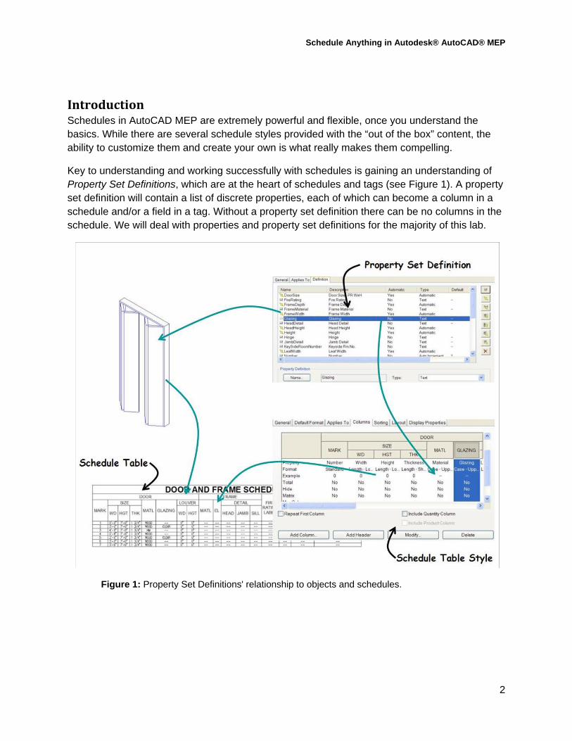
Key to understanding and working successfully with schedules is gaining an understanding of Property Set Definitions, which are at the heart of schedules and tags (see Figure 1). A property set definition will contain a list of discrete properties, each of which can become a column in a schedule and/or a field in a tag. Without a property set definition there can be no columns in the schedule. We will deal with properties and property set definitions for the majority of this lab.
Figure 1: Property Set Definitions' relationship to objects and schedules.

Schedule Anything in Autodesk® AutoCAD® MEP
3
PropertySetDefinitionsandBasicSchedulesIn this segment we'll take a look at the basic functionality of the schedules, tags and property sets that come with AutoCAD MEP and explore how they relate to each other..
CreateanAirTerminalSchedule
Step 1: Launch AutoCAD MEP if it is not already running and set the current Workspace to "HVAC".
Step 2: Open the drawing Schedule Basics.dwg from the lab dataset folder.
Step 3: From the Annotate tab of the ribbon, click Schedules, then Air Terminal Devices Schedule (see Figure 2). When prompted to select objects, window the entire drawing and press <ENTER>. Pick an insertion point to the right of the floor plan, then press <ENTER> again to place the schedule at the right size relative to the current drawing scale.
Figure 2: Creating a schedule using the ribbon.
After placing the schedule you should notice several rows, each one corresponding to one of the diffusers, however all of the schedule cells are populated with question marks. This is because while the schedule "sees" the air terminals, the property sets that the schedule is using for its columns are not attached to them. Property sets used by the schedule must be attached to the objects before they can be reported.
AttachPropertySetDefinitionsBefore attaching property set definitions, make a slight change to your schedule.
Step 4: Select the schedule that you just placed, and in the Properties Palette, set "Update Automatically" to "Yes". De-select the schedule
Note: Normally this step would be moot, as it only applies to schedules that are in the same drawing as the objects that they are reporting. In the context of most workflows this is not the case; usually your schedule is in a drawing that is separate from some or all of the objects being scheduled. More on this later.

Schedule Anything in Autodesk® AutoCAD® MEP
4
Step 5: ZOOM in to the room in the lower left corner of the plan, then select the air terminal shown in Figure 3. In the Properties Palette click on the "Extended Data" tab and click the button at the bottom left of the palette. This is available because there is at least one property set definition that is available for air terminals that has not been attached to the object that is currently selected. In the dialog box that appears note that there is one property set definition listed and it should already be checked. Click OK.
Figure 3: Attaching a property set definition to an object.
Step 6: Deselect the air terminal and select the schedule. Right click and select Update Schedule Table from the menu.
You should now see one cell that has a value in it under the "TAG" column. However all of the other cells are still full of question marks. That's because there are two types of property set definitions, style-based and object-based. You attached an object based property set definition to one object; the rest of the properties that the schedule columns are looking for are contained in a style-based property set definition.
Step 7: Select the same air terminal as before, right click and select Edit MvPart Style from the right click menu. In the MvPart Style Editor dialog, click Property Sets, then click the button at the bottom right of the next dialog box as shown in Figure 4. In the next dialog box, there should be three property sets listed, each with a check mark next to them. Click OK until you exit all dialogs and return to the drawing editor.

Schedule Anything in Autodesk® AutoCAD® MEP
5
Figure 4: Attaching a style-based property set definition.
Now a good portion of the cells are no longer populated by question marks - see Figure 5. They're empty simply because that particular value has not been entered yet, however the schedule is now properly reporting their value.
Figure 5: The result of attaching property set definitions to the MvPart Style.
There is a much easier way of attaching all of the required property set definitions however. When you tag an object, you automatically attach property set definitions to it at the same time.
Step 8: From the Annotate ribbon, choose Tags, then Air Terminal 1 Tag as shown in Figure 6. When prompted to select an object, pick the same terminal you chose earlier. Pick a point a little to the left and above the terminal for the placement point. In the resulting dialog click OK without entering any data yet, then enter M at the command line (for "Multiple"). ZOOM out if necesssary and place a window selection around the drawing, then press <ENTER>. In the dialog that appears, choose No. Again, in the Edit Property Set Data dialog click OK without entering any data yet. Press <ENTER> to end the command.

Schedule Anything in Autodesk® AutoCAD® MEP
6
Figure 6: Placing terminal tags.
Step 9: Select the schedule, right click and select Update Schedule Table.
All of the question marks should now be gone, and all of the rows should indicate a tag number in the first column, however all of the rest of the cells are still empty. Again, this is because those values are still empty in the properties that have now been attached to the MvPart Styles.
EditingStyle‐BasedProperties
Step 10: Select the same air terminal as before, right click and select Edit MvPart Style from the menu. In the Style Editor dialog, click on the Property Sets button. In the Edit Property Set Data dialog, scroll down to the "MAirTerminalsSpecificStyles" property set definition and enter "24x24" next to "Size" as shown in Figure 7. Click OK until you exit all dialogs and return to the drawing editor.
Figure 7: Modifying a style-based property.
Notice that by editing the style-based property, the property for all objects on that style was updated. When defining your own property set definitions, take this into account when you are deciding whether something should be object-based (such as the tag numbers) or style-based.

Schedule Anything in Autodesk® AutoCAD® MEP
7
CreatingCustomPropertySetsNow that you've expored the basics of how property sets, schedules and tags work together, let's dig a little deeper and create some custom property sets from scratch.
Step 11: Open the file 03-Lighting.dwg from the lab dataset folder. Set the current workspace to "Electrical".
Step 12: From the Manage tab of the ribbon, click Style Manager. In Style Manager, expand the "Documentation Objects" folder, then right-click on "Property Set Definitions" and select New. On the "General" tab of the Style editor, change the name of new style to "DeviceLightingStyles", then in the "Applies To" tab, choose Styles and Definitions, then Device Style, then under "Classifications" select Lighting under the "Device Type" classification. (See Figure 8).
Figure 8: Creating a new Property Set Definition for Lighting Device Styles
Note: We will look at the importance of classifications, which are especially important in creating schedules and property sets in AutoCAD MEP, a bit later in this lab.
Step 13: In the "Definition" tab, click the button to create a Manual Property (see Figure 9). Name the property "FixtureType" (note there is no space in the name) and click OK. Next, click the button to create an Automatic Property (see Figure 9). From the list of available Device properties, place a check mark next to "Load" and click OK. Your completed property set should look like the bottom image in Figure 9.

Schedule Anything in Autodesk® AutoCAD® MEP
8
Figure 9: Creating a manual and automatic property.
Now let's create an object-based property set definition.
Step 14: Right click on "Property Set Definitions", click New, and in the "General" tab of the style editor, name the property set definition "DeviceLightingObjects". In the "Applies To" tab, click Objects next to "Applies To", then place a check mark in the box next to "Device". Under "Classifications", place a check mark next to "Lighting" under "Device Type".
Step 15: In the "Definition" tab, add a manual property named "Switchleg". Next, choose the button to add an automatic property. In the Automatic Property Source dialog, place a check mark next to both "Circuit Number" and "Panel-Name", then click OK.
Note that this actually created two automatic properties. Next, we'll add a Location Property. This allows the properties of the space that an object is in to be referenced as a property of the object itself.
Step 16: Click the button to add a Location Property (see Figure 10). In the Location Property Definition dialog box, name the property "SpaceNumber". In the list of property definitions, expand "Space", then "SpaceObjects". Put a check mark in the box next to "Number" as shown in Figure 10 and click OK.
Schedule Anything in Autodesk® AutoCAD® MEP
9
Figure 10: Adding a Location Property.
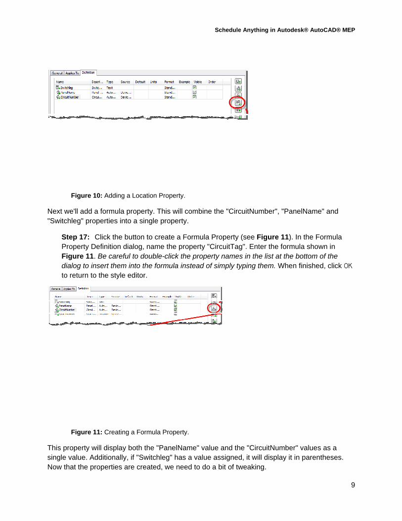
Next we'll add a formula property. This will combine the "CircuitNumber", "PanelName" and "Switchleg" properties into a single property.
Step 17: Click the button to create a Formula Property (see Figure 11). In the Formula Property Definition dialog, name the property "CircuitTag". Enter the formula shown in Figure 11. Be careful to double-click the property names in the list at the bottom of the dialog to insert them into the formula instead of simply typing them. When finished, click OK to return to the style editor.
Figure 11: Creating a Formula Property.
This property will display both the "PanelName" value and the "CircuitNumber" values as a single value. Additionally, if "Switchleg" has a value assigned, it will display it in parentheses. Now that the properties are created, we need to do a bit of tweaking.

Schedule Anything in Autodesk® AutoCAD® MEP
10
Step 18: In the "Definition" tab, enter "1" in the "Order" column for "Switchleg". Uncheck "Visible" for both "CircuitNumber" and "PanelName" as shown in Figure 12.
Figure 12: The completed DeviceLightingObjects Property Set Definition.
This will cause the "Switchleg" property to appear first in the list, and will suppress the display of the two automatic properties - since those properties are only being used to develop the "CircuitTag" properties, there is no reason to confuse the user by having them appear in the Properties palette.
Step 19: Click OK to exit Style Manager and return to the drawing editor.
CreatingCustomObjectTagsNow that we have Property Set Definitions, we can create custom Object Tags and Schedule Table Styles. We'll start with a tag to display the circuit and panel, and the fixture type of each light fixture.
Step 20: In the command window, enter VIEW and press <ENTER>. In the View Manager Dialog, click "Fixture Tag" under "Model Views", then click Set Current. Click OK to return to the drawing editor.
Step 21: From the Home tab of the ribbon, click the drop down menu on the "Annotation" panel, then click Create Tag. When prompted to select objects, select the two pieces of text and the horizontal line between them, then press <ENTER>. In the Define Schedule Tag dialog, enter a name of "MyLightingDeviceTag". Note that the two text fields in your selection set are already listed under the "Label" column. For the "CIRCUIT-TAG" label, click the drop down list under "Type" and choose Property. Under "Property Set", choose DeviceLightingObjects. Under "Propery Definition" choose CircuitTag. For "FIXTURETYPE" choose Property under "Type". Under "Property Set", choose DeviceLightingStyles. Under "Property Definition" choose FixtureType. Your dialog box should look like Figure 13. Click OK. When prompted for the insertion point, snap to the midpoint of the horizontal line.

Schedule Anything in Autodesk® AutoCAD® MEP
11
Figure 13: Creating a custom tag.
After choosing the insertion point, the geometry in the tag should get significantly larger. This is normal. It has been converted to a Multi-View Block, with the text being converted to attributes that reference the properties indicated in the dialog box. Then it is re-inserted according to your current annotation scale. (By default object tags are annotative by nature.)
Step 22: ZOOM "Extents" so that you can see the floor plan and the tag, which will be some distance to the right of the plan.
Step 23: Select the tag, right-click and click Add Selected from the menu. Pick one of the light fixtures in the plan then press <ENTER> to center the tag on the fixture. In the Edit Property Set Data dialog, note that both of the property set definitions are being attached by the tag (if not already attached). Make no changes and click OK. Enter M at the command line and place a window around the entire plan. Press <ENTER>, then in the dialog that appears, click No. In the Edit Property Set Data dialog again, click OK. Press <ENTER> to end the command.
There should now be a tag on top of each light fixture. All of them will have "NA-NA" for the circuit number and panel name values, because they have not yet been assigned to circuits. When they are, however, the tags will automatically update to the new values. Additionally, the fixture type value is completely blank. We'll fix that now.
Step 24: From the Manage tab of the ribbon, click Style Manager. Under "Electrical Objects", expand "Device Styles". There will be four light devices listed among the device styles. Pick the first one, "20x48 Emergency Red" and pick Property Sets on the "General" tab of the style editor. Enter "F1" next to the "FixtureType" property and click OK.
Step 25: Use the same procedure to assign the the Fixture Type designations of "F2", "F3" and "F4" to the remaining light fixture device styles, then click OK to return to the drawing editor.
The tags should be updated now, and should all be showing a value for the fixture type.

Schedule Anything in Autodesk® AutoCAD® MEP
12
CreatingCustomSchedulesWith the same property set definitions, we can also create custom schedules. For our example we'll create a schedule style that will list the light fixtures by type, their loads and the spaces that they are assigned to. (While they may not be visible in this drawing, each room is defined as a space and has a space number assigned to it. The location property that we defined earlier is able to report this number). Further, we'll calculate quantities and totals for the loads and the number of fixtures.
Step 26: From the Manage tab of the ribbon, choose Style Manager. Under "Documentation Objects", select "Schedule Table Styles", right click and choose New from the menu. In the "General" tab of the style editor, name the new schedule style "Lighting Device Schedule".
Step 27: In the "Default Format" tab, set the text style to "RomanS" and the text height to 3/32" as shown in Figure 14.
Figure 14: Setting the default cell format.
Step 28: In the "Applies To" tab, click "Device", then under "Classifications" choose "Lighting" under "Device Type" as shown in Figure 15.
Figure 15: Setting the object types to report in the schedule.

Schedule Anything in Autodesk® AutoCAD® MEP
13
Step 29: In the "Columns" tab, click Add Column. In the Add Column dialog, click on the "SpaceNumber" property as shown in Figure 16, then click OK. Back in the style editor, double click on the column header and change it to "Space".
Figure 16: Creating the first column.
Note: If the "Add Column" button is grayed out, it's because the items you checked in the "Applies To" tab do not match what was checked in the same tab of the property set definition editor. Those values must match for those properties to be available to the schedule.
Step 30: Repeat the preceding step to create columns for "DeviceLightingStyles:FixtureType" and "DeviceLightingStyles:Load".
Step 31: In the "Columns" tab, select the "FixtureType" column and click the Modify button. In the "Heading" box, change the value to "Fixture\PType". The "\P" characters will force a carriage return when the schedule is placed in the drawing. Click OK to return to the style editor.
Step 32: Place a check in the box next to "Include Quantity Column" at the bottom of the editor, then move the "Quantity" column to the far right side of the schedule by dragging and dropping its header on top of the "Load" header.
Step 33: Select the "Quantity" column and click the Modify button. In the Edit Quantity Column dialog, place a check in the box next to "Total" and click OK.
This will cause the light fixture types to be quantified and totaled. Finally, we'll finish off the columns with a Formula column to calculate total loads as well.

Schedule Anything in Autodesk® AutoCAD® MEP
14
Step 34: Click the Add Formula Column button. In the Add Formula Column dialog, enter a heading of "Total". Place a check mark next to "Total". In the "Insert Property Definitions" list, double-click "Load" under "DeviceLightingStyles". Type "*" into the formula, then click Insert Quantity at the bottom of the dialog (see Figure 17). Click OK to return to the Style Editor. Your columns should look like the image on the left side of Figure 18.
Figure 17: Creating a Formula Column.
Step 35: In the "Sorting/Gouping" tab, click Add. Choose "DeviceLightingObjects:SpaceNumber" and click OK. Click Add again and choose "DeviceLightingStyles:FixtureType" and click OK again. The "Sorting/Grouping" tab should like the image on the right side of Figure 18.
Figure 18: Adding the sort columns.

Schedule Anything in Autodesk® AutoCAD® MEP
15
Step 36: Finally, in the "Layout" tab, enter a schedule title of "LIGHT FIXTURE SCHEDULE" and click OK to exit the Style Manager.
Now let's see how our schedule works.
Step 37: From the Annotate tab of the ribbon, click Schedules, then choose any of the schedule styles listed. In the Properties palette, change schedule style to "Lighting Device Schedule" as shown in Figure 19. Window the entire drawing, press <ENTER>, then pick a point to the right of the floor plan and press <ENTER> to insert the schedule.
Your schedule should look like the one in Figure 19. Note that there are several rows that don't show a fixture type value and whose load is 0. These aren't light fixtures, but instead are the switches in those spaces. We'll fix this a bit later in the exercise.
Figure 19: Placing the Light Fixture Schedule.
Let's take advantage of another feature in AutoCAD MEP to make one more adjustment to the schedule. We can group rows by a common value. In this example, we'll group all of the light fixtures (and for now, the switches) by the spaces that they occupy and get subtotals of the loads and fixture counts.
Step 38: Select the schedule, then right-click. Pick Edit Schedule Table Style from the menu. In the "Sorting/Grouping" tab, place check marks in the "Group" and "Display Subtotals for Group" rows under the "DeviceLightingObjects:SpaceNumber" column as

Schedule Anything in Autodesk® AutoCAD® MEP
16
shown in Figure 20, then click OK to return to the drawing editor. Your schedule should now look like the one in Figure 20.
Figure 20: Using the new Grouping and Subtotals feature of schedules.
UsingClassificationsAs stated earlier, Classifications are especially important in AutoCAD MEP. Most things that you will be scheduling will be either MvParts or Devices. However if you could only filter by object type, instead of a schedule only including Air Terminals or Light Fixtures, for example, it would include all MvParts or all Devices. In the same schedule as your Air Terminals, you'd also have Plumbing Fixtures, Mechanical Equipment, Transformers and who knows what else. Classifications allow you further clarify exactly what type of MvPart or Device a particular item is, and also to filter your schedules and property set definitions to only those MvParts and Devices that match the classifications you specify. The reason that the switches are showing up in the schedule is because they were erroneously classified as "Lighting" under the "Devices" classification definition. This is not an error in the software. The default switches that come with AutoCAD MEP are correctly classified. This error was forced in this dataset to illustrate how classifications work.
Step 39: ZOOM in to the room in the lower left corner of the plan. Select the switches near the door and right click. Click Edit Device Style from the menu. In the "Classifications" tab,

Schedule Anything in Autodesk® AutoCAD® MEP
17
click the button next to the "Device Type" classification as shown in Figure 21. Change the "Device Type" classification from "Lighting" to "Switch" and click OK until you return to the drawing editor. Select the schedule and click Update Schedule Table from the menu. It should now look like the one in Figure 21. All of the switches are now removed and only the light fixtures remain.
Figure 21: The effect of classifications.
Whenever you create a new MvPart Style or Device Style, you should make sure to classify it. Similarly, whenever you create property set definitions and schedule table styles, make sure to carefully consider which classifications should be included on the "Applies To" tab.
FinalTweaksNow that you have the fixture tag and the schedule working, it's time to make the tools available to any drawing. Since the schedule table style and the tag only exist in the current drawing, it can only be used in the current drawing. The following steps will make it usable in any file.
Step 40: SAVE the current drawing as Electrical Content.dwg.

Schedule Anything in Autodesk® AutoCAD® MEP
18
NOTE: It is important to save your drawing before creating the standardized content that will be used by other drawings. In this example, we are simulating saving a file that would store ALL custom electrical content that would be used by multiple drawings and potentially multiple users.
Step 41: Right click on the banner at the top of the current tool palette and click New Palette from the menu as shown in Figure 22. Name the palette "Scratch".
Figure 22: Creating a new tool palette.
Step 42: ZOOM in on one of the fixture tags and select it. Without selecting any of the grips, press down on the tag and drag and drop it on top of the new palette. It should create a new tool on the palette.
Step 43: Select the tool, right-click and click Properties. In the Tool Properties dialog, note that most of the information necessary to make the tool has been filled in - the source drawing name and location as well as the MV Block name to use. Click on the Layer Key field and choose the "ANNOBJ" layer key to make the tag come in on the correct layer automatically as shown in Figure 23. Click OK when done until you return to the drawing editor.
Figure 23: Changing the properties of a tool.

Schedule Anything in Autodesk® AutoCAD® MEP
19
Step 44: Finally, test your new tool. Pick one of the tags in the drawing, right-click and choose Select Similar from the menu. Erase all of the tags, then replace them with the tool on the palette. This time they should come in on the layer "G-Anno-Std-Note", which is the layer specified in the "ANNOBJ" layer key.
Step 45: On your own, repeat steps 42-44 to create and test a tool for your light fixture schedule. Set the layer key to "SCHEDOBJ".
ANoteAboutSchedulinginaProjectContextThe previous steps explain how to work with schedules where all of the geometry is in the same file. In most cases however, you will probably be scheduling geometry that exists in multiple files and you might even want the schedule to be in a completely different drawing altogether. This is actually quite simple to do. In the schedule properties you can simply toggle the value for "Schedule External Drawing" to "Yes", then specify the name of that drawing. In that drawing you can XREF all of the files that have the geometry that you want to schedule. When any of those files change the schedule will be updated whenever you open the schedule drawing, or whenever you select the schedule, right-click and choose Update Schedule Table Style. In this workflow of course, the setting to update the schedule automatically is moot and classifications become even more important to make sure you are selecting objects correctly in the remote drawing.
AcknowledgementsMany thanks to Paul Aubin, Darryl Mclelland, Martin Schmidt and Gregg Stanley for allowing me to use one of the datasets from their book "Mastering AutoCAD MEP 2011" for this lab. You can obtain a copy of their latest edition on Paul Aubin's web site: http://paulaubin.com/books/.