scenic automation seminar - creative...
TRANSCRIPT

Scenic Automation By: Gareth Conner President and Founder, Creative Conners, Inc.

Creative Conners Scenic Automation Seminar
www.creativeconners.com Page 2 of 32

Creative Conners Scenic Automation Seminar
www.creativeconners.com Page 3 of 32
Scenic Automation Seminar
Overview Today we are going to discuss, in broad terms, the foundation of scenic automation. The goal is to provide an overview of the most important technical aspects of automation, some examples of machines that demonstrate these technologies, and the resources to get you started developing automated effects. We will begin by discussing the primary components common to most automated systems. Power, Actuators, Power Transmissions, Sensors, Drives, & Motion Controllers are the fundamental categories. Once we have a clear idea of each of these, we’ll take a look at how these components are used together to create some of the basic scenic machines. And finally we’ll conclude with a discussion of how the Creative Conners products can be used to simplify scenic automation. Some of this material may be review, some of it may be hard to grasp after this preliminary introduction. My hope is that from your notes today, you will have some ideas of how to get started on your next project and where to find more information.
Typical automation system
The Basics As with any subject, it helps to know the vocabulary and fundamental concepts before tackling advanced aspects of the subject.
Power – where it all begins Regardless of what you need to move, you will need a source of power. In theatre, this always starts with electricity. As you will see, even fluid power systems (hydraulic/pneumatic) have motors that need electricity?

Creative Conners Scenic Automation Seminar
www.creativeconners.com Page 4 of 32
Mouser trap analogy
Ground
Perhaps the most important concept to electricity is ground. Electricity is attracted to earth. If you generate some current with a voltage higher than ground, that current will seek a path to ground. In fact, it will do so with great force. We can put things in the current’s path and get work done. Grounding is important in automation for two main reasons:
1. Safety – A safety ground connects the case of any conductive device (i.e. the metal housing of a motor, or electrical box) directly to ground. If a wire came loose inside of a device and electrified the case of that device, that current would have a direct and unencumbered path to ground. A large amount of current (measure in amps) would surge through the case until the fuse or circuit breaker popped (normally within a fraction of a second). In such a scenario, if the case weren’t grounded, the next time you touched the case you would become the path to ground. You would get a nasty shock.
2. Noise – Today’s automation gear is packed full of micro-electronics and large power switching amplifiers. With all of the energy being pushed around through miles of wire and circuit board traces, some of the energy radiates off. This unintentional broadcasting can wreak havoc on sensitive equipment and cause all sorts of awful (really, really awful) problems. To combat, or at least limit, these problems we wrap wires in metallic shielding and cover sensitive components in metal enclosures. These enclosures and shields are connected to ground. The radiated energy is then drawn to ground through a path that is not likely to interfere with sensitive equipment.
Where do all of the ground wires go? Into the dirt, somewhere in your building there is a big copper rod that is driven into the ground. Ground wires connect to this rod. On shows where grounding has become a problem (particularly between you and the sound guy), you can visit your local electrical supply house, get a separate ground rod and drive it the earth outside your theatre, this will insure you have a “clean” ground.
Voltage – height of the tower
Current -ball
Ground
Motors, etc. – entertaining widgets

Creative Conners Scenic Automation Seminar
www.creativeconners.com Page 5 of 32
House Power (60Hz AC)
There are 3 common flavors of electricity in theatre: 1. 115VAC – This is the voltage that we are accustomed to having in our homes. It has:
a. One (1) “hot” leg with a potential of 115-120 volts above ground. b. One (1) neutral leg that is at the same potential as ground (0v). c. One (1) ground wire (optional for devices without any accessible metal parts).
2. 208/230vac 1-phase – This is a common voltage in shops and theatres. It has: a. Two (2) “hot” legs. Each leg is 120 volts above ground. The legs are 120
degrees out of phase from each other, giving them a potential of 208 or 230 volts between each other.
b. One (1) ground 3. 230vac 3-phase – Also common in shops and theatres It has:
a. Three (3) “hot” legs. Each leg is 120 volts above ground and 120 degrees out of phase from each other. There is a potential of 230v between each leg.
b. One (1) ground.
Hydraulic Power Units
Hydraulic systems need a reservoir and a pump to store and pressurize oil. The pumps used in theatrical automation are typically driven by electric motors. HPU’s are typically sized by the volume of oil the can pump per minute (GPM) which will determine the maximum speed of your actuator, and the pressure the pump can maintain (PSI) which will determine the force of the actuator. Sizes range for fractional horsepower units that you can plug into a 115vac outlet, to dozens of horsepower units that require high-voltage 3-phase.
Compressors
Pneumatic effects require compressors that are also powered by electric motors. They, like HPU’s, are sized by volume (CFM) and pressure (PSI). You know what a compressor is and does, so I want bore you with more details.
Actuators Once you have a power source, you need to connect that power to something that will do some work.
Motors
There are two primary categories of motors used in scenic automation: AC & DC.
1. DC Motors – There are a few different types of DC motors. DC motors share the characteristic of being motivated by direct current (where the electrical polarity is constant) and that motor speed is controlled by varying the supply voltage.
a. DC-brush type – This is the old workhorse of the industry. Brush type motors have wire windings on the rotor (spinning shaft) and either permanent magnets or wire coils on the stator (motor case). If the motor has wire coils on the stator, it is referred to as “Shunt-wound”. Shunt-wound motors are generally cheaper than Permanent Magnet motors, but do not perform as well. Typical output speed is 1750rpm, horsepower ranges from sub-fractional to in excess of 30 hp. However, common sizes are only available up to 5hp. Pros:
i. Simple, proven technology ii. Speed controls are cheap and simple iii. Linear torque response (good low-speed torque)
Cons: i. Noisy operation ii. Motors are expensive iii. Motors are large

Creative Conners Scenic Automation Seminar
www.creativeconners.com Page 6 of 32
iv. Brushes wear out and need to be replaced.
b. DC brushless – This is a relatively new style of DC motor. These motors are incredibly small, generate a lot of torque, run at high speed (7500), and operate very quietly. The design of a DC brushless places the permanent magnets on the rotor and the windings on the case. This allows the case to act as a heatsink for the windings. It complicates commutation, and requires a microprocessor to energize the windings in the proper sequence to achieve rotation. Pros:
i. Small, light motor design ii. High-torque iii. High-speed iv. Very quiet operation v. No brushes to wear out.
Cons: i. Complex, sensitive speed controllers ii. Expensive motors iii. Expensive speed controllers iv. Generates lots of electrical interference
2. AC Motors – AC motors are rapidly becoming the new workhorse of the industry.
They have combined a number of features of DC-brush and DC-brushless motors to make a good value for theatre. The most typical AC motor used in automation is the induction motor, which requires 3-phase power. The induction motor does not use brushes for commutation. AC motor speed is best controlled by varying the frequency of the current (American power is 60Hz). While you can alter the speed of an AC motor by lowering the voltage (like a ceiling fan), this reduces the torque of the motor. Traditionally, this has been the stumbling block for AC motors in automation. The speed controls (known as VFD’s, variable frequency drives) have been expensive when compared to similar DC speed controls. However, the price of these drives has been steadily falling for the last decade and has reached a price point that is now better than DC equipment when dealing with 2hp motors and greater. Pros:
a. Smaller than DC-brush motors, though still much bigger than DC-brushless. b. Motors are cheap. c. Good torque at low speed with proper speed controls. d. Very quite operation.
Cons: e. Expensive speed controls (getting cheaper) f. Generates lots of electrical interference. g. Complex speed controls can be sensitive and problematic.
Hyrdaulic/Pneumatic Cylinders
Cylinders, either hydraulic or pneumatic, are driven by pressurized fluid (well, air is close enough for pneumatics). Cylinders come in a variety of sizes and are specified by their bore and stroke. Bore refers to the internal diameter of the cylinder body, not the diameter of the piston. Larger bores generate more force, because they allow more pressurized fluid to push the piston and therefore also use more oil. Stroke refers to the distance the piston can move. Strokes can be very long; cylinders can be built with custom lengths relatively cheaply. However, the long stroke cylinders can bend

Creative Conners Scenic Automation Seminar
www.creativeconners.com Page 7 of 32
easily thereby breaking the cylinders seals and leaking. Care must be taken to mechanically guide the piston over long distances. It is important to note that piston-style cylinders have different load capacities for extension and retraction. Because the piston displaces oil, retraction load capacity for a cylinder is a fraction of its extension capacity. Less common type of cylinder is the cable cylinder. Instead of an external piston, the cable cylinder has a wire rope connected to either end of an internal piston. These cylinder can be useful where space is limited and a piston extension isn’t necessary.
Cable cylinder from W.C. Branham
Hydraulic systems are notoriously difficult to control. Manual operation is very simple, computer control can be painful. It is often easier to find an electric motor solution than to automate hydraulic effects. However, it is possible, and we’ll examine the automation techniques for hydraulics a little later on.
Power Transmission Motorized machines almost always need mechanical speed reduction to lower the output speed of the motor and increase the torque.
Speed reducers
Speed reducers are manufactured gear sets that are built within a rigid enclosure. These packaged reducers are often equipped with C-Face mounting flanges that can be bolted directly to a motor. Reducers are sized by ratio (i.e. 40:1) and horsepower. There are many types of speed reducers, but the most commonly used are:
1. Worm gear – These are the most common style. The input and output shafts are perpendicular. Worm gears are difficult to back-drive making them inherently safer for overhauling.
2. Planetary – Extremely efficient, often used with brushless motors. These speed reducers can operate at high RMP and can achieve large reductions (100:1 or greater) in limited space. The input & output shafts are parallel and concentric. Planetary reducers are very easy to back-drive and must always be used with a mechanical brake to prevent slipping.

Creative Conners Scenic Automation Seminar
www.creativeconners.com Page 8 of 32
3. Helical – Input & output shafts are parallel, but not concentric. These reducers are useful when you need an inline reduction (i.e. can’t have perpendicular input/outpt). They are easy to back-drive and must always be used with a mechanical brake.
4. Helical worm – A combination of worm & helical reducers that can achieve higher reductions in a smaller case than standard worm. Very quiet, and hard to back drive.
While it is common to purchase speed reducers that are interchangeable with different motors, products called gearmotors are available that combine the speed reducer and motor into one case. Gearmotors are often available with optional accessories such as brakes and encoders. Though traditionally available in fractional horsepower, companies like SEW & Nord manufacture gearmotors of all sizes. While less flexible than their modular counterparts, gearmotors are often a little cheaper than distinct components.
Brakes
As mentioned in the section on Speed Reducers, many machines need mechanical brakes. The most common brake in stage machinery is the C-Face mounted spring-set brake. These brakes release when energized, and engage when power is lost. The C-face mounting allows them to be mounted between the motor and the speed reducer. This not only makes for a clean assembly, but also allows the brake to utilize the mechanical advantage of the speed reducer. Brakes are commonly 120/208VAC, and can be wired to accept either voltage.
Linear actuators
When you need to replicate the motion of a hydraulic cylinder with an electric motor, linear actuators are a convenient device. Typically built with a AC or DC motor driving either an ACME screw or ball screw, linear actuators telescope like a hydraulic cylinder. Models are usually available with brakes, limit switches, and encoders (though not the ones you can get FedEx’d to you). Many companies also make screw-jack actuators without motors that are equipped with two input shafts, thus allowing you to connect your own motor. This also allows you to link multiple jacks together.
Sensors The big difference between a motorized machine and an automated machine is that an automated machine knows where it is and what it is doing. A table saw is a motorized machine, but has no way to discern which tooth of the blade is entering the wood first. An elevator, on the other hand, knows what floor it is on and where it is going next. It can also maintain a given speed and accelerate and decelerate at a given rate. While it is the controller that directs the motor to move and stop, the controller relies on sensors for information or feedback. There are various sensors that have various uses, but here are the common ones for theatrical use.
Limit Switches
A simple device that has a spring-loaded lever connected to a switch. When the lever is depressed, the switch is activated. Most limit switches have two sets of terminals, 1 normally open, 1 normally closed. Limit switches can be used for simple position feedback to a controller. For instance, if your machine only has 3 or 4 positions a limit switch could be used at each position to stop the machine. Typically, limits are used to prevent a machine (winch, lift, etc.) from traveling too far in either direction. The normally closed terminals are used for end-of-travel limits.

Creative Conners Scenic Automation Seminar
www.creativeconners.com Page 9 of 32
Proximity Sensors
Proximity sensors serve the same purpose as limit switches, but they can sense an object without touching it. This often means better repeatability than a limit switches since there are no sloppy mechanical linkages. There are different varieties of proximity sensors with varying ranges. Some operate on light and some can only detect metal.
Encoders
Encoders are fundamental to automation. Encoders convert motion into a data signal that can then be read by a motion controller to achieve incredibly high position control. The most common encoder is a rotary encoder which has an input shaft meant to connect either to the motor or anything in the machine that is rotating (i.e. the center pivot on a turntable). Rotary encoders are available as either incremental or absolute encoders.
1. Incremental rotary encoder – Incremental encoders generate simple pulses while rotating. You can order encoders with different resolutions that generate anywhere from a couple to a tens of thousands of pulses per revolution. The pulses have to be decoded and counted by the motion controller to determine position. If power is lost to the motion controller, the position information is lost as well. These are inexpensive products, that require inexpensive interface, thus they are more common than absolute encoders. To be useful for position control, the encoder must generate a quadrature signal. This is really two signals, called A & B, that are square waves 90 degrees out of phase. By watching which signal activates first (either A or B) the motion controller can determine what direction the encoder is traveling. Encoders can also be ordered with an index channel (Z), which generates a pulse once per revolution. This feature is often of limited value in stage machines. Quadrature encoders come equipped with different output specifications: a. Differential Line Driver – This output generates equal and opposite signals for
each encoder channel, making four signals (A, /A, B, /B). This balanced signal combats interference from noisy devices (like say, DC brushless drives, or AC variable frequency drives). Noise immunity makes this kind of output preferred for scenic automation.
b. Open collector output & Push-pull – These outputs generate the two signals from the encoder, without any protection from noise. This can reduce the cost of the encoder, but rarely worth the savings as you pull your hair out in tech trying to determine why your machine is losing position.
2. Absolute rotary encoders – Absolute encoders know precisely where the input shaft
is regardless of whether power is lost. These encoders have a limited number of revolutions and a fixed resolution. Position critical applications justify the added expense of these encoders (i.e. tank turrets), rarely used in theatre.

Creative Conners Scenic Automation Seminar
www.creativeconners.com Page 10 of 32
There are also linear encoders that are useful for detecting motion in hydraulic cylinders and other linear machines. The most popular are known as Celesco’s (actually a brand name) which combines a normal rotary encoder with a spring loaded string reel. Pulling the string rotates the encoder’s shaft.
Celesco Encoder
Another style of linear encoder uses a optical sensor that reads a tape with very thin printed lines, similar to a barcode. Though not terribly common, it is a neat device and can be useful in some circumstances.
Renishaw linear encoder
Drives (aka Amplifiers) Regardless of what type of motor powers your machine, an electronic drive is necessary to convert the low voltage speed signal from the motion controller into a high power source for the motor.
AC Vector Drives (inverters)
AC Vector drives are the high-end of variable frequency drives. They exhibit tighter speed regulation than other types of inverters and are suitable for position control applications. The prices range from a few hundred dollars to a couple of thousand dollars depending on the brand and features. Most drives specify a 3-phase power input, some are designed for single-phase input with a 3-phase output. The majority of these drive will actually operate on single phase 208/230VAC, but at ½ the horsepower rating. As mentioned previously AC drives work by varying the frequency of the incoming AC. The drives typically come with a configuration keypad to set a myriad of parameters for the drive
Optical sensor
Encoder tape

Creative Conners Scenic Automation Seminar
www.creativeconners.com Page 11 of 32
to function properly with a motor. It is important to use a motor that is specifically rated for inverter use. VFD’s run very hot and need plenty of air flow to keep them from over-heating and faulting. They also generate all sorts of nasty interference and distort the AC source, so you need to shield them well and isolate the drives with line reactors. It doesn’t hurt to install EMI filters to the drive inputs and RF filters on the drive outputs. If your machine requires quick deceleration or is used in an overhauling application, you will also need to install external breaking resistors to absorb the back-current generated by the motor. To hook your VFD up to a motion controller, you need to make sure that the drive accepts an external signal for speed regulation. Preferably the drive will accept a +/-10vdc signal (that is the most common control signal). Some controllers will also generate two signals 0-10vdc for speed and a separate switch for fwd/rev. Just make sure to check that your motion controller can “talk” to your drive.
Durapulse Vector drive from Automation Direct
DC Regen Drives
To run a DC motor, you need to convert the AC coming out of the wall to DC. While you could you a simple rectifier (see that option a little later), a four-quadrant regenerative DC drive is the best option. A DC regen drive will have the required electronics to decelerate a motor quickly and control an overhauling motor. This means that unlike a VFD, no external braking resistors are required. To control the DC regen drive it will need to be equipped with a isolated inputs for a speed reference signal (-/+10vdc). Most manufacturers offer this as an option, some build isolated inputs into their drives directly.

Creative Conners Scenic Automation Seminar
www.creativeconners.com Page 12 of 32
DC regen drive from Minarik
DC Brushless Drives
DC brushless drives have more in common with VFD’s than DC regen drives. Because the drive handles the high-speed switching of current for commutation, these drives are complex and sensitive. Extra care should be taken with grounding and shielding to insure proper operation. Like VFD’s, these drives usually have a myriad of parameters that need to be set for the drive to work with a specific motor. Unlike VFD’s, these drives lack a handy keypad and instead need to be configured with a computer via a serial or USB cable. Because brushless drives and motors interact intimately it is wise to purchase both components from the same manufacturer. Brushless drives typically come ready to connect to a motion controller, as these drives are most often used in high precision/robotic applications.
Brushless DC drive from Applied Motion Products

Creative Conners Scenic Automation Seminar
www.creativeconners.com Page 13 of 32
Simple DC rectifiers
For driving small DC motors used in little effects, a regen drive may be overkill. If you have a small DC gearmotor that doesn’t need to have much in the way of speed control, a simple bridge rectifier will convert AC to DC and power the motor. Depending on the voltage of the motor, you may need to use a transformer as well. This is a very low-tech, but perhaps all that you need for a simple machine.
Bridge rectifier
Hydraulic Proportional Valves & Drives
Controlling the speed and direction of hydraulics requires the use of proportional valves. These valves are equipped with a precision solenoid that can be driven electrically to vary the flow and path of fluid in the system. Much like electric motors, these electric valves require a drive (or amplifier) to convert the control signal into useable power.
Proportional valve from Vickers
Motion Control Following our bottom-up approach, we’ve covered power, motors, drives, so now it is time to discuss motion control. Without a motion controller, all of these other components have only marginal advantage over moving scenery manually. If you are running every machine with a guy turning a speed knob, you still need a bunch of guys with knobs watch for spike tape on the floor. Thankfully, there are some very cool (and sometimes simple) ways to control machines automatically.

Creative Conners Scenic Automation Seminar
www.creativeconners.com Page 14 of 32
Simple Relay Logic
Starting with the simplest, relay switches coupled with limit switches (or proximity switches) can be used to control motors. Below is an example of a schematic that shows how you might control a motor to move between two positions using just relay switches, a toggle switch, a momentary “GO” button, and a couple of limit switches.
Simple manual control circuit
PLC’s
The next step up from discreet relays is a PLC (programmable logic controller). PLC’s were invented to replace complex relay panels and they excel at that purpose. There are numerous inputs and outputs on a PLC that can be made to perform certain actions through software. PLC’s can also be equipped with encoder interface modules and motion control output allowing the PLC to move beyond simple switch replacement and into full-fledged motion control. With such a PLC you can program position, speed, and acceleration. PLC’s are not the best choice for computerized motion control. The initial purpose of replacing relay boards hampers them with an arcane scripting language known as “Ladder Logic”. Built as a language that would be familiar to electricians that had built relay panels, it lacks the elegance and sophistication of a true programming language. Also, the cost of all of the optional modules that must be added for a standard PLC to become a motion controller surpasses the cost of a dedicated motion controller.

Creative Conners Scenic Automation Seminar
www.creativeconners.com Page 15 of 32
PLC from Automation Direct
Embedded Microprocessors
Dedicated motion controllers built around embedded microprocessors offer a robust, fast, and adaptable platform for controlling motors. These motion controllers are typically programmable either through a scripting language tailored for motion control or through a standard programming language (C, VB, Delphi, etc.) or both. Often these products support Ethernet, RS422, CANBus, ProfiBus or some combination of protocols. Multiple motors (typically 1-8) can be programmed to run to any number of positions at any speed and acceleration. To control more motors, more motion controller can be networked together.
Motion controller from Galil
The Machines Machine design is a big topic. What follows is simply a survey of existing equipment from several scenic automation companies with some basic design notes. One of the first questions that needs to be answered whenever you design a machine is “How much power do I need?” Here in the US, most motors are still sized by horsepower. One (1) horsepower can move 550lbs. 1 foot, in 1 second. This is a great formula to keep in the back of your head. Because if you are asked to design a machine that needs to lift 1000lbs. at a rate of 3’/sec., you can quickly estimate that you need approximately a 6hp motor to do the job (I’d probably go ahead and use a 10hp motor to have plenty of extra power). Of course, you’ll still need to figure out your speed reduction & drum size to get the right performance, but the horsepower is easily known.
Creative Conners Scenic Automation Seminar
www.creativeconners.com Page 16 of 32
Another calculation that comes up frequently is converting horsepower to torque.
Keep in mind that when you are pulling a wagon that is rolling on casters, you are only pulling a fraction of the wagons weight. What’s the fraction? I typically use 20% of the weight to calculate line pull. Why? Well, one day I took a triple swivel caster and loaded it up with 100lbs. I then ran a string from the caster, over a pulley, and tied it to a bucket. I dumped chain into the bucket until the caster started to move. When I weighed the bucket it was 20lbs. So, I figure 20%. I’ve worked with other guys who figure 15%, and their stuff works fine too. Obviously every wagon has a slightly different coefficient of friction that will impact the line pull. If you have to guess, guess a little high. No one ever complains that the motor is running too cool or too quiet.
Winch The winch is perhaps the most versatile stage machine. It can be used for pulling wagons on a deck track, operating traveler tracks, rotating turntables (cable drive), hoisting linesets, lift elevators, etc. A basic winch should have:
1. A motor 2. A speed reducer 3. A grooved drum (between 6” & 12” diameter typically) 4. A drive shaft that connects the drum to the speed reducer 5. Pillow blocks (mounted bearings) for the drive shaft 6. A linkage between the drive shaft and the output of the speed reducer (coupling,
chain, timing belt, u-joint, direct, etc.) 7. An encoder 8. A metal frame that holds everything together
Nice options to have on a winch are:
1. Limit switches 2. Cable keepers 3. Tensioning pulleys 4. A brake 5. A manual override crank
When designing a winch, you need to compute the pulling capacity. Here’s an example using some basic parameters. Motor: 2hp, 1750 rpm Speed reducer: 40:1 Drum: 12” First we compute the output speed of the speed reducer: 1750/40 = 43.75 rpm Next using our torque formula we compute the output torque of the speed reducer: (2 hp * 63025) / 43.75 rpm = 2881 in*lbs of torque
Torque in Inch * Pounds =Horsepower * 63025
Motor RPM (after speed reducer)

Creative Conners Scenic Automation Seminar
www.creativeconners.com Page 17 of 32
Next, compute the pulling force generated by the torque around the drum: (2881 in*lbs) / 6 in = 480 lbs.pulling capacity
Finally, compute the line speed of the cable: (12” * PI) * (43.75rpm/60) = 27.5” per second After completing the target specifications, you need to browse the specifications of each component and make sure they are rated properly.
Pushstick Winch from Creative Conners

Creative Conners Scenic Automation Seminar
www.creativeconners.com Page 18 of 32
Exploded view of Pushstick Winch
Big Tow2 from Stage Technologies Note: The very impressive feature of this winch is that the drum tracks, eliminating any fleet
angle of the cable.
Creative Conners Scenic Automation Seminar
www.creativeconners.com Page 19 of 32
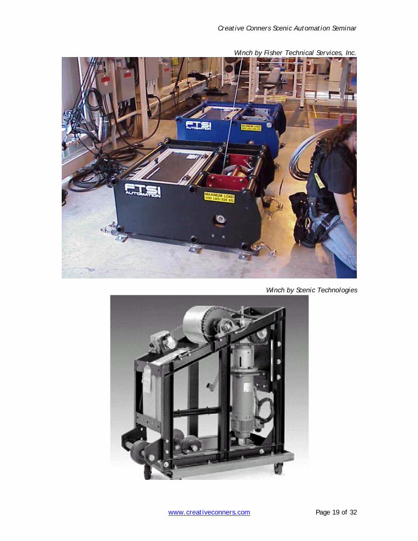
Winch by Fisher Technical Services, Inc.
Winch by Scenic Technologies
Creative Conners Scenic Automation Seminar
www.creativeconners.com Page 20 of 32
Turntable A basic motorized turntable should have:
1. A series of decks that make the top lid. 2. A central pivot bearing. 3. A motor with speed reducer 4. A stationery lower frame that holds inverted casters (a.k.a. spider). Motorized
turntables should typically be built “wheels up”, this means that the casters are fixed and the turntable lid rotates on the caster wheels. This allows wires to be easily run underneath the turntable without be squashed by rolling casters.
5. An encoder (either attached to the motor or directly to the turntable). 6. Some linkage to connect the turntable lid to the motor (examples below).
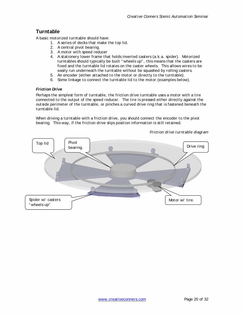
Friction Drive
Perhaps the simplest form of turntable, the friction drive turntable uses a motor with a tire connected to the output of the speed reducer. The tire is pressed either directly against the outside perimeter of the turntable, or pinches a curved drive ring that is fastened beneath the turntable lid. When driving a turntable with a friction drive, you should connect the encoder to the pivot bearing. This way, if the friction drive slips position information is still retained.
Friction drive turntable diagram
Motor w/ tire. Spider w/ casters “wheels up”
Drive ring Pivot bearing.
Top lid
Creative Conners Scenic Automation Seminar
www.creativeconners.com Page 21 of 32
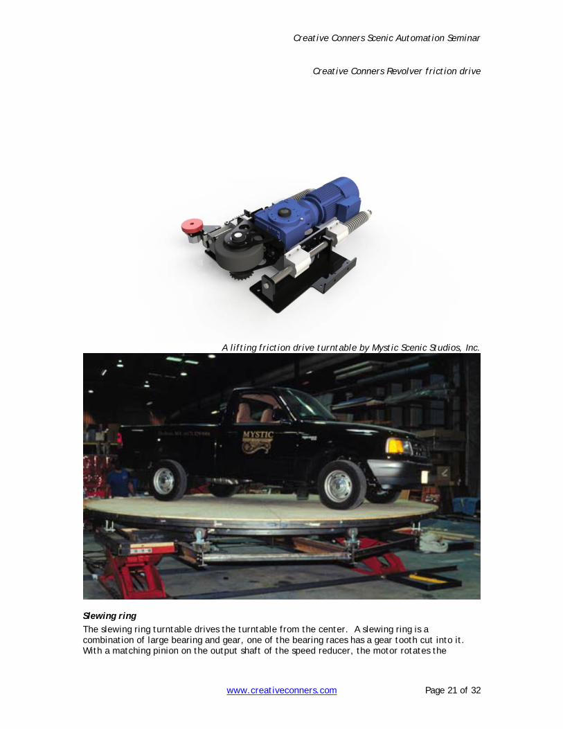
Creative Conners Revolver friction drive
A lifting friction drive turntable by Mystic Scenic Studios, Inc.
Slewing ring
The slewing ring turntable drives the turntable from the center. A slewing ring is a combination of large bearing and gear, one of the bearing races has a gear tooth cut into it. With a matching pinion on the output shaft of the speed reducer, the motor rotates the

Creative Conners Scenic Automation Seminar
www.creativeconners.com Page 22 of 32
turntable from the center with a positive engagement. There is no possibility of slipping in this linkage, so the encoder can be mounted to the motor.
Slewing ring drive turntable diagram
Slewing ring
Timing belt/Chain/Cable drive
Cable drive turntables (and their derivations) operate by wrapping the top lid of the turntable with wire rope (or chain, or timing belt material). Using the friction of the wrapped wire rope, a winch turns the lid by pulling on the wire rope. This type of drive is neither the quietest, nor the most versatile, but it does have the advantage of using a standard winch. A limitation of such a system is that you cannot run the turntable indefinitely; you are limited by the amount of cable you can spool onto your winch drum. Chain & belt drives avoid this problem, but lack the convenience of using a standard winch. Just like the tire drive turntable, cable drive turntables sometimes slip under heavy loads. For this reason make sure to mount the encoder on the center pivot.
Cable-drive turntable diagram

Creative Conners Scenic Automation Seminar
www.creativeconners.com Page 23 of 32
Lift While there are many derivations of the stage lift, the two varieties that are most tried and true are the scissor and the four-post.
Scissor
Typical scissor lifts are hydraulic. Most often scissor lifts are purchased from a manufacturer and just refitted with plumbing to connect to your HPU. Scissors are quick & easy to install, move the lift into place and anchor it to the trap room floor. All of the mechanics necessary to make the lift work are built into the machine, making the lift easily portable (with enough chain motors and fork lifts to haul it around). Two problems need to be addressed when working with scissors. The first is stability. When a scissor lift is fully extended there is typically a couple of inches of sway. Such a large amount of movement is really distressing for performers and can wreak havoc on other wagons that need to drive over the lift. To prevent this problem the lifts need to be guided. Secondly, scissors tend to drift down over time because of small amounts of fluid leaking from one side of the piston to the other. To prevent drift, scissor lifts need external locking pins to hold the lift up.
Scissor lift

Creative Conners Scenic Automation Seminar
www.creativeconners.com Page 24 of 32
Four-post
The four-post lift is, not surprisingly, guided at the corners by four posts. These lifts are simple platforms hung from four cables (1 cable per post). The cables run to a clew which is pulled by either a winch or hydraulic cylinder. Four-post lifts are inherently guided, so they do not face the stability problems of scissors. They are more cumbersome to install than scissors and also clog up the trap room with 4 columns. The columns can make it difficult to roll scenic pieces off the lift in the trap room.
Four-post lift diagram
Friction drive Friction drives are simply a rubber wheel connected to the output shaft of a speed reducer. Typically bolted to the underside of a wagon, friction drives can sometimes replace a deck winch with the following advantages:
1. No need for a raised floor to house winch mechanics and rigging. 2. Able to run with a track or without a track. 3. Able to follow curved tracks easily 4. Quick set up and tear down.
The disadvantages of friction drives are: 1. More height needed inside a wagon to contain the friction drive. 2. The drive wheel can slip, possibly disrupting position information to the motion
controller. This can be overcome by using an idler wheel for the encoder that pressed into the floor.

Creative Conners Scenic Automation Seminar
www.creativeconners.com Page 25 of 32
Below are some pictures of a friction drive design. I developed this drive while working at Mystic Scenic Studios. This drive can easily follow serpentine curves with a radius as little as 4’. The wheel is spring loaded to compensate for inconsistencies in the floor. The motor used is a brushless DC, capable of pushing wagons up to 3 tons in a 3” profile.
Friction drive elevation
Prototype of Friction Drive during testing

Creative Conners Scenic Automation Seminar
www.creativeconners.com Page 26 of 32
Turtle A turtle is a popular scenery machine that combines a friction drive with a slewing ring to make a tracking turntable.
Turtle being assembled
Controlling the Machines The final piece of equipment in a scenic automation system is the operator interface. Built around either a PC or master PLC, the operator interface allows motor movements to be programmed and recorded. Different systems offer special features, but common to most systems are abilities to:
1. Control a number of motors at the same time 2. Store movements as cues 3. Link multiple cues together 4. Jog motors manually 5. Tune motors
The last item “Tune motors” deserves some explanation. Every motion controller generates a motion profile for every motor movement. This motion profile is a map that the controller follows to give a motor the proper speed signal at the proper times to insure that the motor accelerates, achieves the programmed speed, and decelerates in time to stop the motor exactly on the programmed position. The controller manages this by checking the motor’s encoder at regular intervals and comparing it to the profile. The real world seldom matches the theoretical profile, and so the controller has to decide how to correct the motors speed to get it back on track. The controller has a formula with three variable gains that it uses to determine how to correct the speed. The three gains are Proportional, Integral, and Differential, often referred to as PID’s. Tuning a motor is the process of discovering the proper settings for these gains to achieve smooth motion. I like to think of tuning a motor as an analogy to building a cruise control for a car. You want the car to stay at a 65mph on its trip, but to maintain that speed you need to constantly adjust the amount of fuel supplied to the engine. If you are going up a hill, you need more fuel. If you are coasting down a hill, you need less fuel. If the cruise control adjusts too much and goes above 65mph it has to let off the gas and coast back down. Following that analogy,

Creative Conners Scenic Automation Seminar
www.creativeconners.com Page 27 of 32
Proportional Gain is the amount of gas supplied to correct the speed. Too high a value and the car will be jerky as it bounces between 60mph up to 70mph and then back down to 60mph. Too low a value and the car won’t maintain 65mph going up a hill. Derivative Gain can be though of as a shock absorber attached the gas pedal, it smoothes out the jerkiness of the Proportional Gain corrections. Sampling is how often the cruise control checks the speed on the wheels. As mentioned in the section on motion controllers, many purchased components come with programming interfaces that allow you to develop your own application interface and hook into the motion controller. To build such a system requires that you know a programming language such as C, C++,C#, Visual Basic, REALBasic, Delphi, or Java. Below are some pictures of different companies motion controllers and consoles.
Creative Conners Stagehand AC motion controller and VFD

Creative Conners Scenic Automation Seminar
www.creativeconners.com Page 28 of 32
Creative Conners Spikemark scenic automation software
Creative Conners Showstopper emergency stop panel

Creative Conners Scenic Automation Seminar
www.creativeconners.com Page 29 of 32
ShowMotion AC2 console
ShowMotion AC2 drive racks

Creative Conners Scenic Automation Seminar
www.creativeconners.com Page 30 of 32
Fisher Technical Services drive racks
Stage Technologies Nomad console
Stage Technologies Maxis Drive pack

Creative Conners Scenic Automation Seminar
www.creativeconners.com Page 31 of 32
Scenic Technologies Stage Commander Console
Scenic Technologies Mini Commander Interface

Creative Conners Scenic Automation Seminar
www.creativeconners.com Page 32 of 32
Interesting sites Creative Conners Inc. www.creativeconners.com scenic automation equipment McMaster-Carr www.mcmastercarr.com tons of mechanical parts Grainger www.grainger.com tons of mechanical parts Compumotor www.compumotor.com brushless DC motors Automation Direct www.automationdirect.com sensors, motors, PLC’s Encoders.com www.encoders.com encoders Martin www.martinsprocket.com sprockets, gears Ralmark www.ralmark.com nice pulleys Dynapar www.dynapar-encoders.com encoders Leeson www.leeson.com motors Minarik www.minarikdrives.com motors/drives SEW www.sew-eurodrive.com ac gearmotors Springer controls www.springercontrols.com rotary limit switches Kaydon www.kaydon.com bearings, slewing rings Avon Bearings www.avonbearings.com bearings, slewing rings Mouser www.mouser.com electronics Rabbit Semiconductor www.rabbitsemiconductor.com embedded microprocessors Vickers www.hydraulics.eaton.com hydraulic servo & pro. Valves Allen Bradley www.ab.com tons of motion equipment