scenario-focused three-dimensional computational …soilquake.net/openseespl/elgsft.pdf ·...
TRANSCRIPT

Scenario-focused three-dimensional computational modeling in geomechanics Modélisation tri-dimensionelle de calcul en géomécanique base sur l’étude de scenarios
A. Elgamal & J. Lu University of California, San Diego, La Jolla, California, USA
Z. Yang California Department of Transportation, Oakland, California, USA
T. Shantz California Department of Transportation, Sacramento, California, USA
ABSTRACT Three-dimensional nonlinear finite element simulations are becoming increasingly feasible for geotechnical applications. This paper presents a versatile framework that helps streamline the use of three-dimensional finite elements for analyses of soil and soil-structure systems. In this regard, a Windows-based graphical-user-interface OpenSeesPL is developed for footing/pile-ground interaction analyses. OpenSeesPL allows convenient studies of three-dimensional seismic (earthquake) and/or push-over pile analyses. Various ground modification scenarios may be also addressed by appropriate specification of the material within the pile zone. The presented analysis scenarios aim to highlight the analysis framework capabilities and range of potential applications.
RÉSUMÉ Les simulations tri-dimensionelles nonlinéaires par éléments finis deviennent de plus en plus réalisables dans le domaine de la géotechnique. Cet article présente un cadre de calcul polyvalent qui facilite l’utilisation d’éléments finis tri-dimensionelles pour les analyses de sol et de systèmes sol-structure. A cet égard, un interface d’utilisateur graphique de calcul basé sur Windows, OpenSeesPL, est dévelopé pour les analyses d’intéraction sol-fondation/pieux. OpenSeesPL permets d’étudier le comportement des systèmes de fondation sur pieux soumis à des charges sismiques dynamiques et/ou des charges quasi statiques. Différents scénarios de modification des sols peuvent être aussi examinés par spécification appropriée des matériaux dans la zone des fondations à pieux. Les scénarios de modélisation présentés visent à mettre en évidence les capacités du cadre de calcul et le spectre d’applications potentielles. Keywords : Geotechnical, Finite Element, Pile Foundations, Earthquake, Seismic, Numerical modeling
1 INTRODUCTION
Soil-Foundation-Structure Interaction (SFSI) is an important aspect affecting the performance of structures such as buildings and bridges. With the recent developments in numerical modeling techniques and high-speed efficient computers, linear and nonlinear three-dimensional (3D) finite-element (FE) methods are becoming an effective technique for understanding the involved SFSI mechanisms. Particularly suited to seismic applications, the open-source computational platform OpenSees (Mazzoni et al. 2006) provides such 3D simulation capabilities.
However, in conducting numerical simulations, preparation of the FE data file is a step that requires careful attention. A minor oversight might go undetected, leading to erroneous results. Numerous opportunities for such small errors abound, and a user-friendly interface can significantly alleviate this problem, and allow for high efficiency and much increased confidence.
On this basis, a user-interface “OpenSeesPL” is under development (Figures 1 and 2), to allow for the execution of push-over and seismic footing/pile-ground simulations (Lu et al. 2006, https://neesforge.nees.org/projects/openseespl/). Various ground modification scenarios may be also studied by appropriate specification of the material within the pile zone.
In the following sections, an overview of OpenSeesPL capabilities is presented, followed by a range of potential simulation scenarios. As such, the aim is to highlight the analysis framework capabilities and range of potential applications.
2 COMPUTATIONAL FRAMEWORK The open-source platform OpenSees (http://opensees. berkeley.edu, Mazzoni et al. 2006) is employed throughout. OpenSees is a software framework for developing applications to simulate the performance of structural and geotechnical systems subjected to earthquakes. OpenSees can be used to study the performance of infrastructure facilities (bridges, buildings, etc.) under static loads, and during earthquake events.
In the OpenSees platform, a wide range of linear and nonlinear soil and structural elements is available. The reported pre- and post-processing scenarios are generated by the user interface OpenSeesPL (http://cyclic.ucsd.edu/ openseespl) which allows for: i) convenient generation of the mesh and associated boundary conditions and loading parameters (FE input file), ii) execution of the computations using the OpenSees platform, and iii) graphical display of the results for the footing/pile and the ground system. 3. MODELING CONFIGURATIONS
The OpenSeesPL graphical interface (pre- and post-
processor) is focused on facilitating a wide class of 3D studies (with additional capabilities yet under development). The basic default configuration is in the
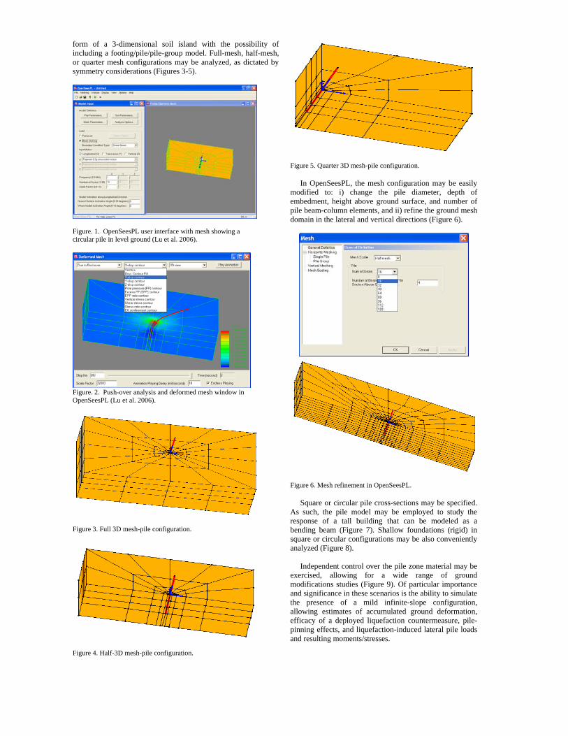
form of a 3-dimensional soil island with the possibility of including a footing/pile/pile-group model. Full-mesh, half-mesh, or quarter mesh configurations may be analyzed, as dictated by symmetry considerations (Figures 3-5).
Figure. 1. OpenSeesPL user interface with mesh showing a circular pile in level ground (Lu et al. 2006).
Figure. 2. Push-over analysis and deformed mesh window in OpenSeesPL (Lu et al. 2006).
Figure 3. Full 3D mesh-pile configuration.
Figure 4. Half-3D mesh-pile configuration.
Figure 5. Quarter 3D mesh-pile configuration.
In OpenSeesPL, the mesh configuration may be easily modified to: i) change the pile diameter, depth of embedment, height above ground surface, and number of pile beam-column elements, and ii) refine the ground mesh domain in the lateral and vertical directions (Figure 6).
Figure 6. Mesh refinement in OpenSeesPL.
Square or circular pile cross-sections may be specified. As such, the pile model may be employed to study the response of a tall building that can be modeled as a bending beam (Figure 7). Shallow foundations (rigid) in square or circular configurations may be also conveniently analyzed (Figure 8).
Independent control over the pile zone material may be exercised, allowing for a wide range of ground modifications studies (Figure 9). Of particular importance and significance in these scenarios is the ability to simulate the presence of a mild infinite-slope configuration, allowing estimates of accumulated ground deformation, efficacy of a deployed liquefaction countermeasure, pile-pinning effects, and liquefaction-induced lateral pile loads and resulting moments/stresses.

Figure 7. Building modeled as a bending beam on a shallow foundation embedded in the ground.
Figure 8. Circular shallow foundation model.
Material for the pile-soil interfacing zone may be also specified by the user, permitting scenarios such as analysis of cylindrical foundations, and/or control over pile-soil friction and potential no-tension interaction during lateral deformation (Figure 10). In addition to the footing and single pile configurations, pile groups may be also represented in the free head or fixed head configurations (Figure 11).
Figure 9. Control over specification of soil inside the pile zone.
4. LOAD APPLICATION Static and dynamic loads may be applied. For static loading, push-over type analyses may be conducted where the loads/moments are directly applied to the pile top or footing surface, in force or in displacement modes (Figure 12). Capabilities are provided for monotonic loading, cyclic loading, and for user-defined load patterns to be uploaded as text file. Push-over along the finite element mesh boundary may be also specified, for instance to explore loads on pile foundations due to lateral ground displacement (Figure 13).
Figure 10. Control over specification of pile-soil interfacing zone.
Figure 11. Large pile group model (1/2 mesh configuration).
Dynamic and earthquake shaking may be also imparted along the soil lower boundary (base). Shaking is allowed in 3D with a small set of available motions, and a capability to upload user specified base shaking excitation (Figure 14).
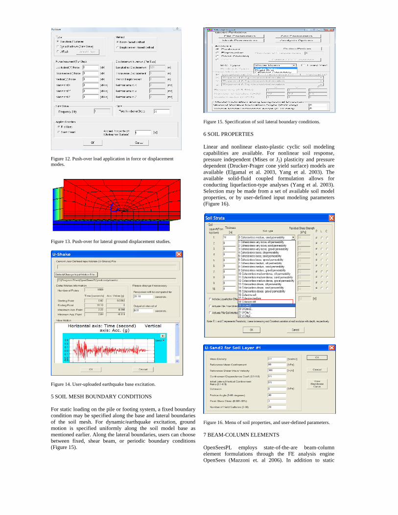
Figure 12. Push-over load application in force or displacement modes.
Figure 13. Push-over for lateral ground displacement studies.
Figure 14. User-uploaded earthquake base excitation. 5 SOIL MESH BOUNDARY CONDITIONS For static loading on the pile or footing system, a fixed boundary condition may be specified along the base and lateral boundaries of the soil mesh. For dynamic/earthquake excitation, ground motion is specified uniformly along the soil model base as mentioned earlier. Along the lateral boundaries, users can choose between fixed, shear beam, or periodic boundary conditions (Figure 15).
Figure 15. Specification of soil lateral boundary conditions. 6 SOIL PROPERTIES
Linear and nonlinear elasto-plastic cyclic soil modeling capabilities are available. For nonlinear soil response, pressure independent (Mises or J2) plasticity and pressure dependent (Drucker-Prager cone yield surface) models are available (Elgamal et al. 2003, Yang et al. 2003). The available solid-fluid coupled formulation allows for conducting liquefaction-type analyses (Yang et al. 2003). Selection may be made from a set of available soil model properties, or by user-defined input modeling parameters (Figure 16).
Figure 16. Menu of soil properties, and user-defined parameters. 7 BEAM-COLUMN ELEMENTS OpenSeesPL employs state-of-the-are beam-column element formulations through the FE analysis engine OpenSees (Mazzoni et. al 2006). In addition to static

analysis, these elements allow for dynamic/cyclic earthquake-type simulations. Linear, bilinear hysteretic, and nonlinear fiber element formulations are available (Mazzoni et al. 2006), based on steel and concrete cyclic constitutive models. Using OpenSeesPL, the beam column modeling properties may be specified, and a display of the resulting moment-curvature relationship can be generated as shown in Figure 17. 8. VISCOUS DAMPING For dynamic computations, viscous damping at the level of the entire model may be specified conveniently. A dedicated interface allows users to define damping ratios at two different frequencies, according to the Rayleigh mass-stiffness damping logic. Conversely, the mass and stiffness matrix viscous damping multipliers may be specified directly (Figure 18). 9. POST-PROCESSING Upon specification of the model parameters, the interface accesses the FE OpenSees platform to conduct the computations. If needed, own weight is applied first (soil domain followed by super-structure), nonlinear material properties are activated, and the specified loading scenario is finally executed (static or dynamic/earthquake loading).
Figure 17. Fiber section and moment-curvature relationship.
Figure 18. Control over Rayleigh mass, stiffness viscous damping.
Upon completion of the computational phase, display of the results is initiated by OpenSeesPL. The structure response may be viewed as time histories and/or as response at various levels of the applied static load (Figures 19 and 20). The deformed mesh may be also viewed (Figures 2, 11), with capabilities for animation and display of conditions after application of own weight only, and after execution of the static/dynamic load computations. Contour quantities such as displacement, strain, stress, pore pressure, and stress-ratio (stress-state relative to failure condition) may be viewed (Figure 13).
Figure 19. Display of response time histories.
Figure 20. Pile displacement load-step display (monotonic load).

10. EXAMPLE SIMULATION SCENARIOS I. Elgamal and Lu (2009a) conducted a pilot study of lateral loading on a 3x3 pile group. A single-pile FE model was first calibrated in the linear range based on the 3D analytical solution of Abedzadeh and Pak (2004). Response of this linear pile in an idealized nonlinear undrained-clay material was then computed and compared to the linear solution. The corresponding 3x3 pile group response was also addressed, as a function of pile-spacing for the above linear and nonlinear soil cases (Figures 21 and 22).
Figure 21. FE mesh of 3x3 pile group (1/2 mesh due to symmetry). II. In a remediated area of large spatial extent (Figure 23), the periodic boundary technique offers an effective approach for conducting 3D analyses (i.e., symmetry allows the investigation of a representative remediated “cell”). On this basis, Elgamal et al. (2009b) conducted a 3D FE ground modification parametric study, to evaluate mitigation of liquefaction-induced lateral soil deformation by the stone column and the pile pinning approaches. An effective-stress plasticity-based formulation was employed. Using OpenSeesPL, a half-mesh was studied due to symmetry (Figure 23). A 10 m depth mildly-inclined (4 degrees) saturated layer was analyzed, with the remediated zone diameter maintained at 0.6 m throughout. Liquefaction-induced lateral deformation and remediation procedures for mildly sloping sand and silt strata were investigated under the action of an applied earthquake excitation. The extent of deployed remediation (area replacement ratio) and effect of the installed stone column permeability were analyzed. Effect of lateral spreading on the pile response was also investigated.
Figure 22. Plan view of displacement around piles for 5 (above) and 7 (below) pile-diameter spacing (1/2 mesh configuration, with red color denoting the large displacement zones).
Figure 23. Ground modification study for mitigation of liquefaction-induced lateral deformation (above showing pattern of stone column construction, and periodic boundary logic, and below showing plan and side-views of FE mesh (1/2 mesh due to symmetry). 11. SUMMARY AND CONCLUSIONS A robust and versatile framework for computational analysis of pile-ground systems was presented. The open-source platform OpenSees is employed throughout. For illustration, scenarios of lateral response of pile groups, as well as ground remediation against liquefaction-induced lateral spreading were discussed. The conducted investigations aim to highlight the analysis framework capabilities and range of potential applications. ACKNOWLEDGMENT The authors are grateful for the funding provided by the Pacific Earthquake Engineering Research (PEER) Center, the US National Science foundation Grant No. 0529995, and the PEER Lifelines program.
REFERENCES
Abedzadeh, F., and Pak, Y.S. 2004. “Continuum Mechanics of Lateral Soil–Pile Interaction.” Journal of Engineering Mechanics, Vol. 130 (11): 1309-1318.
Elgamal, A., Yang, Z., Parra, E., and Ragheb, A. 2003. Modeling of cyclic mobility in saturated cohesionless soils. International Journal of Plasticity, 19(6), 883-905.
Elgamal, A., and Lu, J. 2009a. A Framework for 3D finite element analysis of lateral pile system response, Proceedings of the 2009 International Foundation Congress and Equipment Expo, Contemporary Topics in In Situ Testing, Analysis, and Reliability of Foundations, ASCE GSP 186, M. Iskander, D. F. Laefer, and M. H. Hussein, Editors, Orlando, Florida, March 15–19, pp. 616-623.
Elgamal, A., Jinchi Lu, J., and Forcellini, D. 2009b. Mitigation of liquefaction-induced lateral deformation in a sloping stratum: 3D numerical simulation, Journal of geotechnical and geoenvironmental engineering, ASCE, to appear.
Lu, J., Yang, Z., and Elgamal, A. 2006. Openseespl three-dimensional lateral pile-ground interaction version 1.00 user's manual, Report No. SSRP-06/03, Department of Structural Engineering, University of California, San Diego, La Jolla, CA.
Mazzoni, S., McKenna, F., and Fenves, G. L. 2006. Open system for earthquake engineering simulation user manual, Pacific Earthquake Engineering Research Center, University of California, Berkeley (http://opensees.berkeley.edu/).
Yang, Z., Elgamal, A., and Parra, E. 2003. A computational model for cyclic mobility and associated shear deformation, Journal of Geotechnical and Geoenvironmental Engineering, 129 (12), 1119-1127.