scc - stress corrosion cracking of stainless steel · of ni (uns n02200) in caustic evaporators...
TRANSCRIPT
STAINLESS STEEL 408
ALKAllES
Sodium Hyd.$oride
Bodlum hydjoxlde solutions at eompsratively low temperatures and concentrations bra quite noncorrosive to both the chromium and chromlum- nickel alloya. Higher and inconsistent corrosion rates ocour in more con- centrated solutions and are somewhat accelerated under applied pressure’2.
?lypical corrosion rates for several stainless steels are shown in Table 16.32. Potassium hydroxide eolutiona would be expected to show similar action on stainless steela.
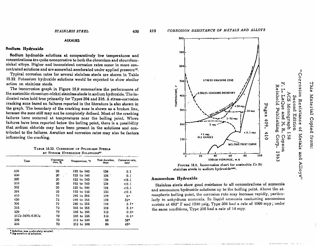
The isocorrosion graph in Figure 16,Q summarizes the performance of the austenitic chromium-nickel atsinless ateels in aodium hydroxide. The in- dicated retie hold true prirqerily for Typeci 304 and 316. A atreaa-corrosion cracking zone baaed on faihrea reported in the literature is also shown in the graph. The boundary of ‘the cracking cone is shown aa a broken line, because the cone still may not be completely defined. Moat of the cracking failures have occurred at temperaturea near the boiling point. Where failures have been reported below the boiling point, there is a possibility that sodium chloride may have been piesent in the aolutiona and con- tributed to the failures. Aeration and corrosion rates may also be factors influencing the crack’ing.
TABLE 16.32. CORROSION or STAINLEM RTEELB
BY Hmtou Hvnnoxwm SOLUTIONS~~ -
Type CW&C;lll$. Tempcrdurc, ‘F I
Tcylw;hm, Corradon de, wv
- -_
410 20 122 to 140 134 0.1 430 20 122 to 140 134 ( 0.1 309 20 122 to 140 134 <O.l 310 20 122 to 140 134 <O.l 302 20 122 to 140 134 <O.l 304 22 122 to 140 133 <O.l 410 72 245 to 265 119 G’ 430 72 245 to 265 110 32. 304 72 246 to 265 110 3.7’ 310 72 246 to 266 110 3.1’ 329 72 246 to 256 110 0.3’ 21Cr-34Ni-0.6Cu 72 246 to 256 119 0.1. 302 73 212 to 248 RR 38b aw 73 212 to 248 88 46b
’ Solution w4 modernldy rcrdd. b Nr rerallun of durioo.
410 CORROSION RESISTANCE OF METALS AND ALLOYS
STRESS CRACKING ZONE
loo- ALLCRADES
o : i /I 1 I
0 20 40' . 60 80
SODIUM HVDROXIDE,ti%
FIOURE 16.8. I&corrosion ohart for auetenitic Cr-Ni stainleae steele in sodium hydroxidel”A.
Ammonium Hydroxide
Stainless steela ahow good resistance to all concentrations of ammonia and ammonium hydroxide solutions up to the boiling point. Above the at- mospheric boiling point, the corrosion rate may increase rapidly, particu- larly in anhydrous ammonia. In liquid omiironis contuining ummonium acetate at 483” F and 1200 psi& Type 304 hnd a rate of 1060 mpy; under the same conditione, ‘I’yl~c 316 had a rate of 14 mpy.
_ ._.. _._._ _ . ___-..__ __ _..-.--.-- ____.. __.._ .-.......-...- -.------.--.--~- .-
MATERIALS SELECTION & DESIGN
Corrosion of stainless steel by hot caustic
Research using solutions of
chemically pure caustic (sodium hydroxide [NaOH]) led to the
development of a diagram that
attempts to delineate the param-
eters of concentration and tem-
perature governing stress corrosion cracking (SCC) of type 300 series austenitic stainless steels
(SS), such as types 304 (UNS
S30400), 316 (S31600), and their low-carbon forms, types 304L
(S30403) and 316L (S31603). This diagram (Figure 1) is analogous to
a similar diagram for caustic
embrittlement of carbon steel un-
der stress from welding or cold- forming. The term caustic
embrittlement is a misnomer be-
cause the phenomenon is simply SCC of steel in the alkaline
solution.
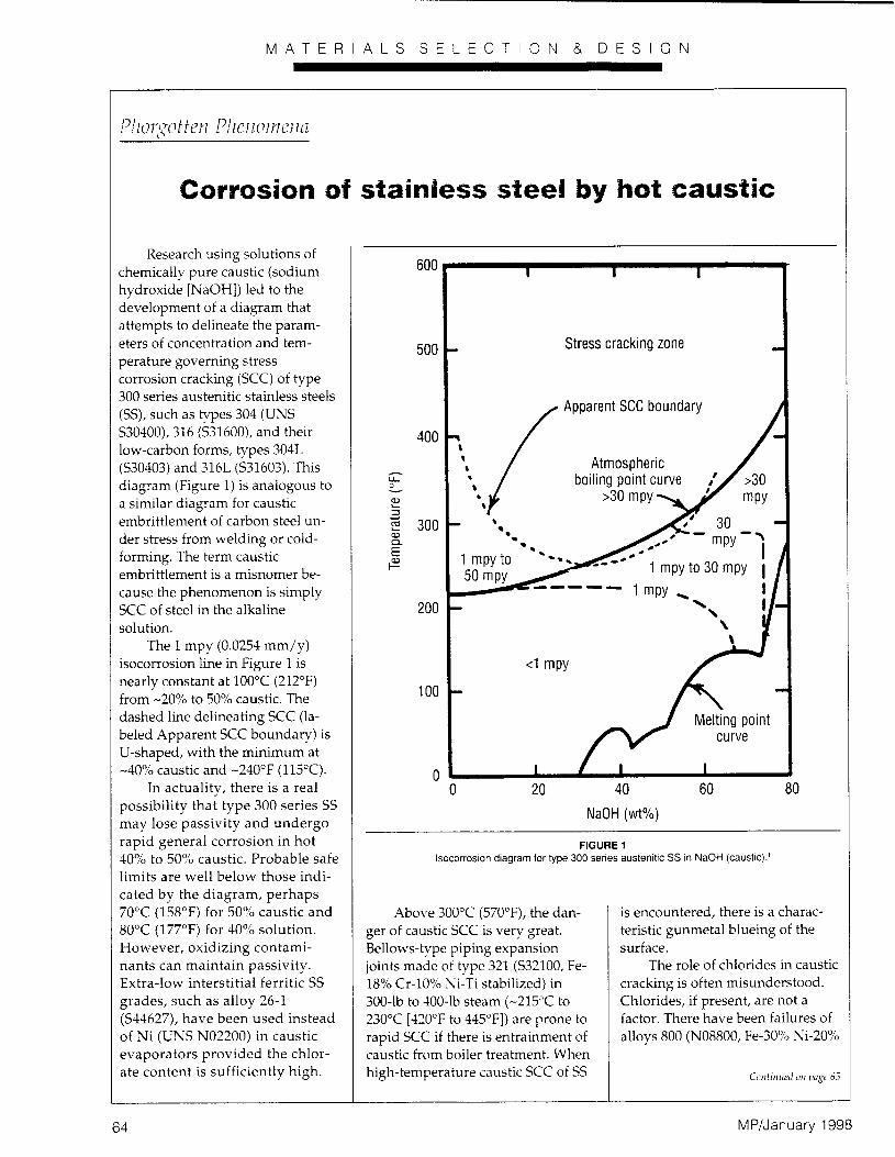
The 1 mpy (0.0254 mm/y) isocorrosion line in Figure 1 is
nearly constant at 100°C (212°F) from -20% to 50% caustic. The
dashed line delineating SCC (la-
beled Apparent SCC boundary) is U-shaped, with the minimum at
-40% caustic and -240°F (115’C). In actuality, there is a real
possibility that type 300 series SS
may lose passivity and undergo
rapid general corrosion in hot 40% to 50% caustic. Probable safe
limits are well below those indi-
cated by the diagram, perhaps 70°C (158°F) for 50% caustic and 80°C (177°F) for 40% solution.
However, oxidizing contami- nants can maintain passivity.
Extra-low interstitial ferritic SS
grades, such as alloy 26-l
(S44627), have been used instead of Ni (UNS N02200) in caustic evaporators provided the chlor-
ate content is sufficiently high.
600 8 1 1 I
&
500 - Stress cracking zone -
Apparent SCC boundary
0 20 40
NaOH (wt%)
60 80
FIGURE 1 lsocorroslon diagram for type 300 series austenitlc SS in NaOH (caustic).’
Above 300°C (570”F), the dan- ger of caustic SCC is very great.
Bellows-type piping expansion joints made of type 321 (S32100, Fe-
18% Cr-10% Ni-Ti stabilized) in
300-lb to 400-lb steam (-215’C to 230°C [QO”F to 445”F]) are prone to
rapid SCC if there is entrainment of caustic from boiler treatment. When high-temperature caustic SCC of SS
is encountered, there is a charac-
teristic gunmetal blueing of the
surface. The role of chlorides in caustic
cracking is often misunderstood.
Chlorides, if present, are not a factor. There have been failures of
alloys 800 (NOSSOO, Fe-30% Ni-20%
64 MP/January 1998
i
MATERIALS SELECTION & DESIGN
Phorgotten Phenomena <Ollh,llrd frO,?l {"Z,yC bi
Cr) and 825 (N08825, Fe-40% Ni-2096 Cr-3% MO-~% Cu), high-
Ni alloys that are very resistant to
chloride SCC, used as replace-
ments for type 300 series SS. Rus- Sian investigators reported that
chlorides, a common contaminant
in concentrated caustic, do not aggravate SCC and may even play
an inhibitive role.
Alloy 600 (N06600, Ni-15%
Cr-8% Fe ) is satisfactory in hot
caustic service. For bellows, alloy 625 (N06625, Ni-20% Cr-8% Mo-Cb
stabilized) is currently used almost
exclusively.
C.P. Dillon, FNACE
C.P. Dillon 0 Associates
940 Park Street
St. Albans, WV 25177
Reference I J K. .l’elwn. “M,~termls ot Cmstructmn tar Alka- lies md Hypochlorites,” in Process lndustms Cor- roz~n-k Throw mJ Practice. cds. 13.1. Llonu. 1Y.I. Poilock (Hw&, TX. -LACE. l%h), p. XIU.
Corrosion Scientists, Engineers, Practitioners...
S/fare your “Plmgotten Phe~mmerux”
iterlzs zuitll your colleayues. Articles
sliodd be 1,000 zuords or 1ess;photos
md drmings me nppreciated. Srnd
subnzissions to Warren 1. Pollock, MP
Tecllnicrzl Editor, NACE, P.0. Bus
215340, Houston, TX 77215-8340.
C.P. Dillon is the 1998 NACE International T.J.
Hull Award recipient for his outstanding con-
tributions In the field or puhlicatlons. He is the
author oi Corrosion Control in the Chemical
Process Industries, 2nd Edition (St. Louis, IMO:
MTI, lYY;~, now in its second printing. This
book is available irom NACE.
WANT CERTIFICATION? Consider taking a course.
Corrosion Technician and Corrosion Technologist Certifications at-e now on a parallel path
through education!
By taking specified courses and successfully passing the course exams, you can apply for certification without further testing. (Application and additional documentation required.)
For more details, call Sonia Bell in the NACE certification department at phone: 281/228-6214.
MP/January 1998 Circle 129 on Reader Serwce Card
NACE REPORT
“Impressed Current Anodes for Underground
Cathodic Protection Systems” is now
available.
This new consensus-approved technical committee report pro- vides an overview of impressed current anode materials for those new to the cathodic protection field and serves as a reference for more experienced personnel.
Addresses six commonly used anode materials:
+ graphite
+ high-silicon chromium cast iron
+ mixed-metal oxide
+ platinum-coated niobium, titanium, and tantalum
+ polymeric materials
+ scrap steel
To order, contact NACE Membership Services
Phone: 281/228-6223
Fox: 281/228-6329
Emoil: [email protected]
$14 List, $10 NACE Member item R4190
ONACE’ THE CORROSION SOCIETY
Circle 130 on Reader Service Card 65
STRESS CORROSION CRACKING
Stress corrosion cracking is something which the de- ‘gn engineer should always keep in mind in specifying
haterials, particularly in the case of pressure vessels. The presence of internal stress should always be taken into account when deciding the magnitude of exter- nally applied stresses to which the equipment can be safely subjected. Unfortunately there are no guiding rules which can be followed. About all that can be said is that stress corrosion cracking is specific both for the metal and for the environment. In certain special environments the presence of tensile stresses may lead to the cracking of certain metals. With other environ- ments or with other metals or alloys no difficulty is encountered. Reliance must be placed on practical experience or on laboratory or field tests.
The term stress corrosion cracking is used to indicate the combined action of static tensile stress and corro- sion which leads to cracking. The principal factors are the magnitude of the stress, the nature of the environ- ment, the length of time involved and the internal structure of the alloy. These factors are not independ- ent, but interact, one accelerating the action of another. Their relative importance varies with conditions.
If stress corrosion cracking is to occur there must be tensile stresses at the surface. The stresses may be in- ternal or applied, the two types being additive. Ex- -mples of internal stresses are those produced by de-
wrmation during cold work, by unequal cooling from high temperature and by internal structural rearrange- ments involving volume changes. Stresses induced when a piece is deformed, those induced by press and shrink fits and those near welds, rivets and bolts may be classed as internal stresses.
In many cases these concealed stresses are of greater importance than actual operating stresses. This is true also of pressure vessels, except perhaps for those operating at loads which are high in relation to the strength of the material. When the factor of safety required in design is considered, operating stresses are generally low enough to be of comparatively little importance, except as they add to the internal stresses.
The actual stresses may vary greatly from point to point within the metal, and in some locations are much higher than the average value. A nonuniform stress distribution is expected, nevertheless a high localized stress is considered more damaging than a uniform load. Generally tensile stresses in the neighborhood of the yield strength are present in stress corrosion crack- ing failures, but failures are known which have occurred at much lower stresses. In any case the stress levels are low enough so that normally a great deal of general corrosion could be tolerated. The interaction of the
stess and corrosion produces cracking where it would Tot otherwise be expected.
Stress corrosion cracking has been observed in almost all metal systems. Yet for each metal specific environ- ments are required to produce it. No stress corrosion
cracking has occurred in a vacuum. The environment that induces cracking frequently attacks the metal only superficially if stresses are absent. Many of the en- vironments that cause cracking tend to produce a pit- ting type of corrosion.
One of the curious aspects of stress corrosion cracking is the wide difference in time required for failure, which varies from a matter of minutes to many years. Asso- ciated with this is the probability of cracking. Speci- mens which are apparently similar may not behave alike, with perhaps 40% cracking in a short time, and the rest remaining untracked for a much longer time. Labora- tory tests require severe conditions to produce crack- ing in reasonable time, whereas in service much milder conditions may cause cracking in the longer time avail- able.
Considerable time may be required before corrosion proceeds to the extent that it begins to be accelerated by the tensile stresses present. The more severe the corrosive conditions and the higher the stress level the sooner this will happen. With some alloys there is an incubation period, during which precipitation or other structural changes may be occurring. For example, aluminum-magnesium alloys (over 6% magnesium), immediately after heat treatment, may not show any susceptibility to cracking in accelerated laboratory tests, but after aging at room temperature for 6 months, stress corrosion cracks may form rapidly in the same test.
As just indicated the internal structure of the metal or alloy can be of considerable importance. The in- ternal structure is dependent upon composition, upon the method of fabrication and whether the metal is as- cast, hot worked or cold worked. It is also dependent on thermal treatments and the extent of natural aging.
There have been numerous reviews and books on stressc orrosion cracking.gv 20-24 There is also a volu- minous literature. This should be consulted for de- tailed information. The more important instances of stress corrosion cracking are discussed below.
Caustic Embrittlement
A well-known example of st.ress corrosion cracking is the caustic embrittlement of steel in steam boilers.25 The cracking is associated with the presence of sodium hydroxide in the boiler and hence the name caustic em- brittlement. The metal away from the cracks, how- ever, is ductile and not brittle. When a boiler lets go because of caustic embrittlement, results can be dis- astrous as illustrated in Fig. 1.26 Other examples of severe explosions have been cited by Zapffe.27
The cracking is said usually to be predominantly intercrystalline, and Fig. 2 is an illustration of this. This photomicrograph was prepared from the steel of an autoclave exposed to 507a caustic soda at 250’ F and 400 psi. This is perhaps a more concentrated solution than normally encountered in steam boilers,
.but it is an excellent example of caustic embrittlement just the same. Oxides are present in the cracks, which
5
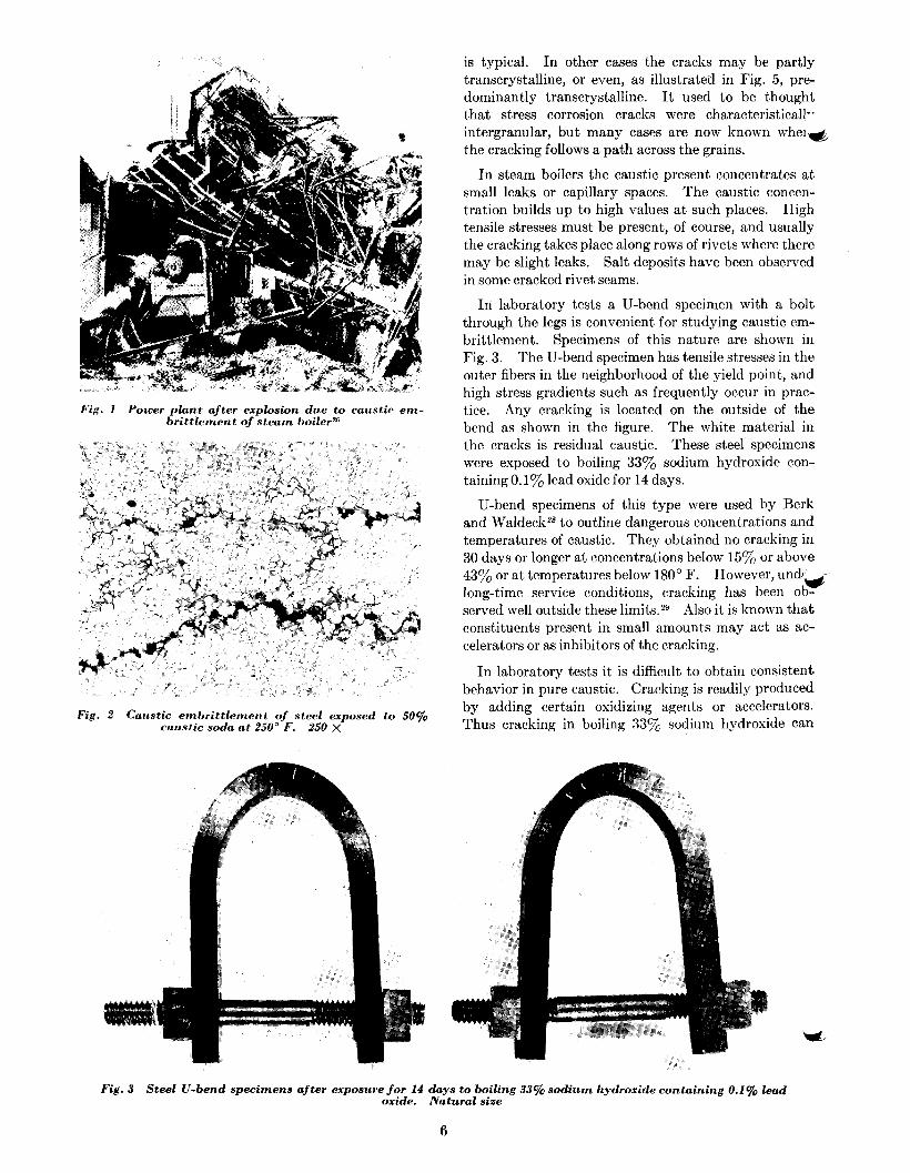
Fig. 1 Power plant after explosion due to caustic em- brittlement of steam boile+
Fig. 2 Caustic embrittlement of steel exposed to 50% caustic soda at 250” F. 250 X
is typical. In other cases the cracks may be partly transcrystalline, or even, as illustrated in Fig. 5, pre- dominantly transcrystalline. It used to be thought that stress corrosion cracks were characteristicall-- intergranular, but many cases are now known whei& the cracking follows a path across the grains.
In steam boilers the caustic present concentrates at small leaks or capillary spaces. The caustic concen- tration builds up to high values at such places. High tensile stresses must be present, of course, and usually the cracking takes place along rows of rivets where there may be slight leaks. Salt deposits have been observed in some cracked rivet seams.
In laboratory tests a U-bend specimen with a bolt through the legs is convenient for studying caustic em- brittlement. Specimens of this nature are shown in Fig. 3. The U-bend specimen has tensile stresses in the outer fibers in the neighborhood of the yield point, and high stress gradients such as frequently occur in prac- tice. Any cracking is located on the outside of the bend as shown in the figure. The white material in the cracks is residual caustic. These steel specimens were exposed to boiling 33oj, sodium hydroxide con- taining 0.1% lead oxide for 14 days.
U-bend specimens of this type were used by Berk and Waldeckz8 to outline dangerous concentrations and temperatures of caustic. They obtained no cracking in 30 days or longer at concentrations below 15y0 or above 43% or at temperatures below 180’ F. However, und!Ci long-time service conditions, cracking has been ob- served well outside these limits29 Also it is known that constituents present in small amounts may act as ac- celerators or as inhibitors of the cracking.
In laboratory tests it is difficult to obtain consistent behavior in pure caustic. Cracking is readily produced by adding certain oxidizing agents or accelerators. Thus cracking in boiling 33% sodium hydroxide can
Fig. 3 Steel U-bend specimens aj-ter exposure for 14 days to boiling 33% sodium hydroxide containing 0.1% lead oxide. Natural size
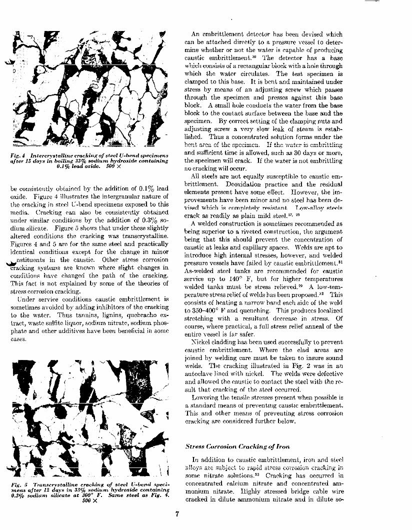
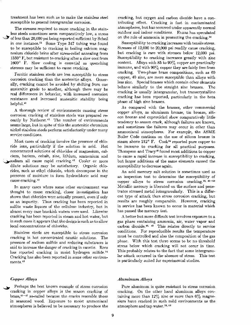
Fig. 4 Intercrystalline cracking of steel U-bend specimens after 15 days in boiling 33q0 sodium hydroxide containing
0.1% lead oxide. 500 X
be consistently obtained by the addition of 0.1% lead oxide. Figure 4 illustrates the intergranular nature of the cracking in steel U-bend specimens exposed to this media. Cracking can also be consistently obtained under similar conditions by the addition of 0.3% so- dium silicate. Figure 5 shows that under these slightly altered conditions the cracking was transcrystalline. Figures 4 and 5 are for the same steel and practically identical conditions except for the change in minor
* nstituents in the caustic. Other stress corrosion
cracking systems are known where slight changes in conditions have changed the path of the cracking. This fact is not explained by some of the theories of stress corrosion cracking.
Under service conditions caustic embrittlement is sometimes avoided by adding inhibitors of the cracking to the water. Thus tannins, lignins, quebracho ex- tract, waste sulfite liquor, sodium nitrate, sodium phos- phate and other additives have been beneficial in some cases.
Fig. 5 Transcrystalline cracking of steel U-bend speci- mens after 12 days in 33% sodium hydroxide containing 0.3% sodium silicate at 300” F. Same steel as Fig. 4.
500 x
An embrittlement detector has been devised which can be attached directly to a pressure vessel to deter- mine whether or not the water is capable of producing caustic embrittlement.30 The detector has a base which consists of a rectangular block with a hole through which the water circulates. The test specimen is clamped to this base. It is bent and maintained under stress by means of an adjusting screw which passes through the specimen and presses against this base block. A small hole conducts the water from the base block to the contact surface between the base and the specimen. By correct setting of the clamping nuts and adjusting screw a very slow leak of steam is estab- lished. Thus a concentrated solution forms under the bent area of the specimen. If the water is embrittling and sufficient time is allowed, such as 30 days or more, the specimen will crack. If the water is not embrittling no cracking will occur.
All steels are not equally susceptible to caustic em- brittlement. Deoxidation practice and the residual elements present have some effect. However, the im- provements have been minor and no steel has been de- vised which is completely resistant. Low-alloy steels crack as readily as plain mild stee1.z7s 29
A welded construction is sometimes recommended as being superior to a riveted construction, the argument being that this should prevent the concentration of caustic at leaks and capillary spaces. Welds are apt to introduce high internal stresses, however, and welded pressure vessels have failed by caustic embrittlement.31 As-welded steel tanks are recommended for caustic service up to 140’ F, but for higher temperatures welded tanks must be stress relieved.*9 A low-tem- perature stress relief of welds has been proposed.32 This consists of heating a narrow band each side of the weld to 350-400’ F and quenching. This produces localized stretching with a resultant decrease in stress. Of course, where practical, a full stress relief anneal of the entire vessel is far safer.
Nickel cladding has been used successfully to prevent caustic embrittlement. Where the clad areas are joined by welding care must be taken to insure sound welds. The cracking illustrated in Fig. 2 was in an autoclave lined with nickel. The welds were defective and allowed the caustic to contact the steel with the re- sult that cracking of the steel occurred.
Lowering the tensile stresses present when possible is a standard means of preventing caustic embrittlement. This and other means of preventing stress corrosion cracking are considered further below.
Stress Corrosion Cracking of Iron
In addition to caustic embrittlement, iron and steel ‘alloys are subject to rapid stress corrosion cracking in some nitrate solutions.33 Cracking has occurred in concentrated calcium nitrate and concentrated am- monium nitrate. Highly stressed bridge cable wire cracked in dilute ammonium nitrate and in dilute so-
7
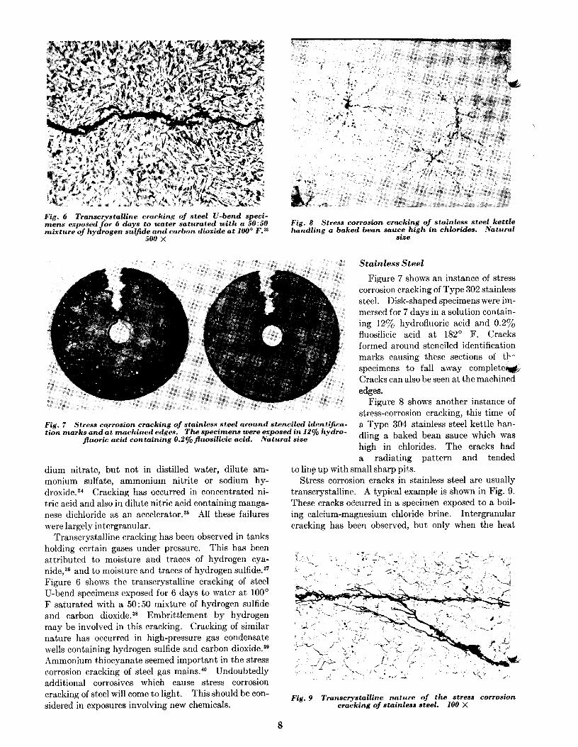
Fig. 6 Transcrystalline cracking of steel U-bend speci- mens exposed for 6 days to water saturated with a 50150 mixture of hydrogen sulfide and carbon dioxide at 100” F.%
500 x
Fig. 8 Stress corrosion cracking of stainless steel kettle handling a baked bean sauce high in chlorides. Natural
size
Stainless Steel
Figure 7 shows an instance of stress corrosion cracking of Type 302 stainless steel. Disk-shaped specimens were im- mersed for 7 days in a solution contain- ing 12% hydrofluoric acid and 0.2% fluosilicic acid at 182’ F. Cracks formed around stenciled identification marks causing these sections of tb- specimens to fall away completer& Cracks can also be seen at the machined
edges.
Fig. 7 Stress corrosion cracking of stainless steel around stenciled identijica- tion marks and at machined edges. The specimens were exposed in 12% hydro-
fluoric acid containing O.2~ejluosilicic acid. Natural sire
Figure 8 shows another instance of stress-corrosion cracking, this time of a Type 304 stainless steel kettle han- dling a baked bean sauce which was high in chlorides. The cracks had a radiating pattern and tended
dium nitrate, but not in distilled water, dilute am- monium sulfate, ammonium nitrite or sodium hy- droxide.34 Cracking has occurred in concentrated ni- tric acid and also in dilute nitric acid containing manga- nese dichloride as an accelerator.35 All these failures were largely intergranular.
Transcrystalline cracking has been observed in tanks holding certain gases under pressure. This has been attributed to moisture and traces of hydrogen cya- nide,3a and to moisture and traces of hydrogen sulfide.3’ Figure 6 shows the transcrystalline cracking of steel U-bend specimens exposed for 6 days to water at 100’ F saturated with a SO:50 mixture of hydrogen sulfide and carbon dioxide.38 Embrittlement by hydrogen may be involved in this cracking. Cracking of similar nature has occurred in high-pressure gas condensate wells containing hydrogen sulfide and carbon dioxide.3g Ammonium thiocyanate seemed important in the stress corrosion cracking of steel gas mains.*O Undoubtedly additional corrosives which cause stress corrosion cracking of steel will come to light. This should be con- sidered in exposures involving new chemicals.
to line up with small sharp pits. Stress corrosion cracks in stainless steel are usually
transcrystalline. A typical example is shown in Fig. 9. These cracks occurred in a specimen exposed to a boil- ing calcium-magnesium chloride brine. Intergranular cracking has been observed, but only when the heat
Fig. 9 Transcrystalline nature of the stress corrosion cracking of stainless steel. 100 X
8
treatment has been such as to make the stainless steel susceptible to general intergranular corrosion.
The stresses required to cause cracking in the stain-
.& less steels sometimes seem comparatively low, a stress of less than 20,000 psi being reported sufficient by Scheil in one instance.23 Some Type 347 tubing was found to be susceptible to cracking in boiling calcium mag- nesium chloride brine after stress-relief annealing from 1350’ F, but resistant to cracking after a slow cool from 1600’ F. Slow cooling is essential as quenching stresses may be sufficient to cause cracking.
Ferritic stainless steels are less susceptible to stress corrosion cracking than the austenitic alloys. Gener- ally, cracking cannot be avoided by shifting from one austenitic grade to another, although there may be real differences in behavior, with increased corrosion resistance and increased austenitic stability being helpfu14i
A thorough review of environments causing stress corrosion cracking of stainless steels was prepared re- cently by Nathorst.42 The number of environments seems large, but in spite of this the austenitic chromium nickel stainless steels perform satisfactorily under many service conditions.
Most cases of cracking involve the presence of chlo- ride ions, particularly if the solution is acid. Hot concentrated solutions of chlorides of magnesium, cal- cium, barium, cobalt, zinc, lithium, ammonium and
-&sodium all cause rapid cracking.43 Cooler or more dilute solutions may be satisfactory. Organic chlo- rides, such as ethyl chloride, which decompose in the presence of moisture to form hydrochloric acid may cause cracking.44
In many cases where some other environment was thought to cause cracking, closer investigation has shown that chlorides were actually present, even if only as an impurity. Thus cracking has been reported in sulfite waste liquors of the cellulose industry, but in almost every case brackish waters were used. Likewise cracking has been reported in steam and hot water, but in such cases it appears that the design is such as to allow local concentrations of chlorides.
Stainless steels are susceptible to stress corrosion cracking in hot concentrated caustic solutions. The presence of sodium sulfide and reducing substances is said to increase the danger of cracking in caustic. Rees has reported cracking in moist hydrogen sulfide.24 Cracking has also been reported in some other environ- ments.42
cracking, but oxygen and carbon dioxide have a con- tributing effect. Cracking is fast in contaminated atmospheres, but has occurred under apparently normal outdoor and indoor conditions. Evans has speculated on the role of ammonia in promoting the cracking.24
Susceptibility to cracking increases with tensile stress. Stresses of 12,000 to 20,000 psi readily cause cracking, but cracking is rare with stresses below 12,000 psi. Susceptibility to cracking increases greatly with zinc content. Alloys with 85 to 90% copper are practically immune, and with 90% copper they are fairly free from cracking. Two-phase brass compositions, such as 60 copper, 40 zinc, are more susceptible than alloys with less zinc. Special brasses which contain other elements behave similarly to the straight zinc brasses. The cracking is usually intergranular, but transcrystalline cracking has been reported, particularly in the beta phase of high zinc brasses.
As compared with the brasses, other commercial copper alloys, as aluminum bronze, tin bronze, sili- con bronze and cupronickel show comparatively little tendency to season crack, although failures are known, and sometimes the failures may occur in other than ammoniacal atmospheres. For example, the ASME Boiler Code cautions on the use of silicon bronze in steam above 212’ F. Cook24 reported pure copper to be immune to cracking for all practical purposes. Thompson and Tracy4* found most additions to copper to cause a rapid increase in susceptibility to cracking, but larger additions of the same elements caused the susceptibility to decrease again.
An acid mercury salt solution is sometimes used as an inspection test to determine the susceptibility of copper alloys to stress corrosion cracking.2g, 4g--62 Metallic mercury is liberated on the surface and pene- trates stressed metal intergranularly. This is a differ- ent type of attack than stress corrosion cracking, but results are roughly comparable. However, cracking in service has been known to occur in material which has passed the mercury test.
A better but more difficult test involves exposure to a gas phase containing ammonia, air, water vapor and carbon dioxide.48+ 4g This relates directly to service conditions. For reproducible results the temperature must be controlled and also the composition of the gas phase. With this test there seems to be no threshold stress below which cracking will not occur in time. This probably relates to the fact that some intergranu- lar attack occurred in the absence of stress. This test is particularly suited for experimental studies.
Co
* Perhaps the best known example of stress corrosion Pure aluminum is quite resistant to stress corrosion cracking in copper alloys is the season cracking of cracking. On the other hand aluminum alloys con- brass,45-47 so-called because the cracks resemble those taining more than 12% zinc or more than 6% magne- in seasoned wood. Exposure to moist ammoniacal sium have cracked in such mild environments as the atmospheres is believed to be necessary to produce the atmosphere and tap water.‘” 63
9