scattering of sh-waves by a shallow circular lined tunnel...
TRANSCRIPT
Ground Support 2016 — E. Nordlund, T.H. Jones and A. Eitzenberger (eds)
Ground Support 2016, Luleå, Sweden | 1
Scattering of SH-waves by a shallow circular lined tunnel with
an imperfect interface
C.P. Yi, Luleå University of Technology, Sweden
D. Johansson, Luleå University of Technology, Sweden
U.Nyberg, Luleå University of Technology, Sweden
Abstract
The analytic solutions for the dynamic response of a shallow circular lined tunnel with an imperfectly bonded interface subjected to plane SH-waves are presented in the paper. Complex variable method was used and the imperfect interface was modelled with a linear spring model. The case that the rock is harder than the liner was investigated. The effects of the contact stiffness of the interface, the incident angle, the frequency of the incident wave and the depth of the tunnel were investigated. The results indicate when the frequency of incident waves is low, the variation of contact stiffness of the imperfect interface has a slight effect on the distribution of dynamic stress concentration factor (DSCF) in the rock mass but there is a significant effect on the distribution of DSCF in the liner. When the frequency of incident waves is high, the distribution of DSCF is complicated in the rock mass and in the liner. The variation of the depth of tunnel leads to the cyclical variation of DSCF. The incident angle significantly affects the distribution and value of DSCF. The phenomenon of resonance scattering can be observed when the bond of the interface is extremely weak.
1 Introduction
Underground structures play an important role in the infrastructure of modern society, since they are involved in a number of applications ranging from storage to transportation systems. It is generally assumed that underground structures suffer appreciably less damage under seismic conditions than structures on the surface and, in particular, that such damage diminishes with increasing overburden depth (Hashash et al., 2001). However, some tunnels were seen to suffer damage beyond the limits of possible refurbishment during earthquakes (Uenishi and Sakurai 2000; Li 2012). In order to provide a safe condition for the underground structure, it is necessary to design the support system of underground facilities to withstand static overburden loads as well as to accommodate the additional deformations imposed by the earthquake induced motions (Hasheminejad and Miri 2008). Consequently, development of a suitable analysis as part of the design methodology for assessment of the dynamic interaction effects between the lining and its surrounding media when subjected to seismic waves is crucial for earthquake and civil engineers (Hashash et al., 2005).
Extensive efforts have been dedicated to studying the dynamic response of lined or unlined tunnels. Using the wave function expansion method, Pao and Mow (1973) initiatively studied dynamic stress concentration of single cavity in the whole space for incident elastic plane P waves. Lee (1977) used complex variable solution for incident SH wave to cylindrical cavity. Hwang and Lysmer (1981) used a special FEM in frequency domain for dynamic analysis of buried structures to plane travelling wave. Datta and Shah (1982) undertook a study on wave scattering around single or multiple cavities. The series expansion method was used by Zeng and Cakmak (1985) to investigate the scattering of plane SH waves by multiple cavities in both an infinite and a half space. Kattis et al. (2003) studied 2D dynamic response of unlined and lined tunnels in poroelastic soil to harmonic body waves. Dynamic response of twin lined

Scattering of SH-waves by a shallow circular lined tunnel with an imperfect interface C.P. Yi, D. Johansson, U.Nyberg
2 |Ground Support 2016, Luleå, Sweden
tunnels buried in an infinite medium and subjected to seismic loadings was investigated by Moore and Guan (1996) using the successive reflection method.
The effect of surface topography on seismic wave propagation is an important topic for earthquake engineering. Liang et al. (2003, 2004) used Fourier–Bessel expansions to derive a series solution of the displacement response of the ground surface in the presence of underground twin tunnels subjected to excitation of incident plane SV and P waves. In their works, the half surface was replaced by a convex circular surface of large radius. Qi et al. (2003) investigated the dynamic response of shallow lined structure by incident SH-wave using multi polar coordinates system method. Liu et al. (2013) presented an analytical solution for scattering of plane harmonic P, SV or Rayleigh waves by a shallow lined circular tunnel in an elastic half space based on the plane complex variable theory and the image technique.
Generally, the interface between the tunnel and the liner is treated as perfectly bonded in previous studies, which means that the traction and displacement on the interface are continuous. In practice, interface bonding is often imperfect because of the presence of microcracks or interstitial media in the interface. It is therefore of technological interest to study to what extent the response of the system is affected by the imperfect bonding between the liner and the surrounding rock. Yi et al (2014a) investigated the effect of imperfect interface on the dynamic response of lined tunnel under incident cylindrical P-waves by using a spring model to model the contact between the tunnel and the liner. Yi et al. (2014b) also investigated the effect of imperfect interface on the dynamic response of lined tunnel under incident SH-waves in a whole space.
The primary goal of the paper is to study the scattering of SH-waves by a shallow circular lined tunnel with an imperfect interface. Here, a shallow lined tunnel means the lined tunnel is in a half space, i.e., the effect of the ground surface should be taken into account. In this paper, the effects of the contact stiffness of the interface, the incident angle, the frequency of the incident wave and the depth of the tunnel on the dynamic response of the lined tunnel are investigated.
2 Governing equations
2.1 SH-waves in solid
In xy-plane, the motion W (x,y,t) excited by SH-wave is normal to xy-plane and independent of z. It is governed by the two-dimensional wave equation.
2 2 2
2 2 2 2
1
y ts
W W W
x c
1)
where, sC
is the shear wave velocity, ρ and μ are mass density and shear modulus, respectively.
For the case of a harmonic SH-wave, assuming ( , ) i tW w x y e , eq. (1) can be rewritten as:
2 22
2 20
y
w ww
x
(2)
where, w is the displacement, sc/ is the wave number of the incident wave, 2 f is the circular
frequency and f is the frequency of the incident wave.
After omitting the time factor of i te
, the relationship between stress and strain is as follows
( , ) , ( , )xz yz
w wx y x y
x y
(3)

Seismic/Dynamic Issues 2 - Support
Ground Support 2016, Luleå, Sweden | 3
By introducing a complex variable ( z x yi , z x yi ), 1i , in the complex plane ( z , z ), eqs. (2)
and (3) can be written as
2
210
4
ww
z z
(4)
( ), ( )xz yz
w w w wi
z zz z
(5)
In the polar coordinates, eq. (5) can be written as
( e e ), ( e e )i i i i
rz z
w w w wi
z zz z
(6)
2.2 Waves in rock mass
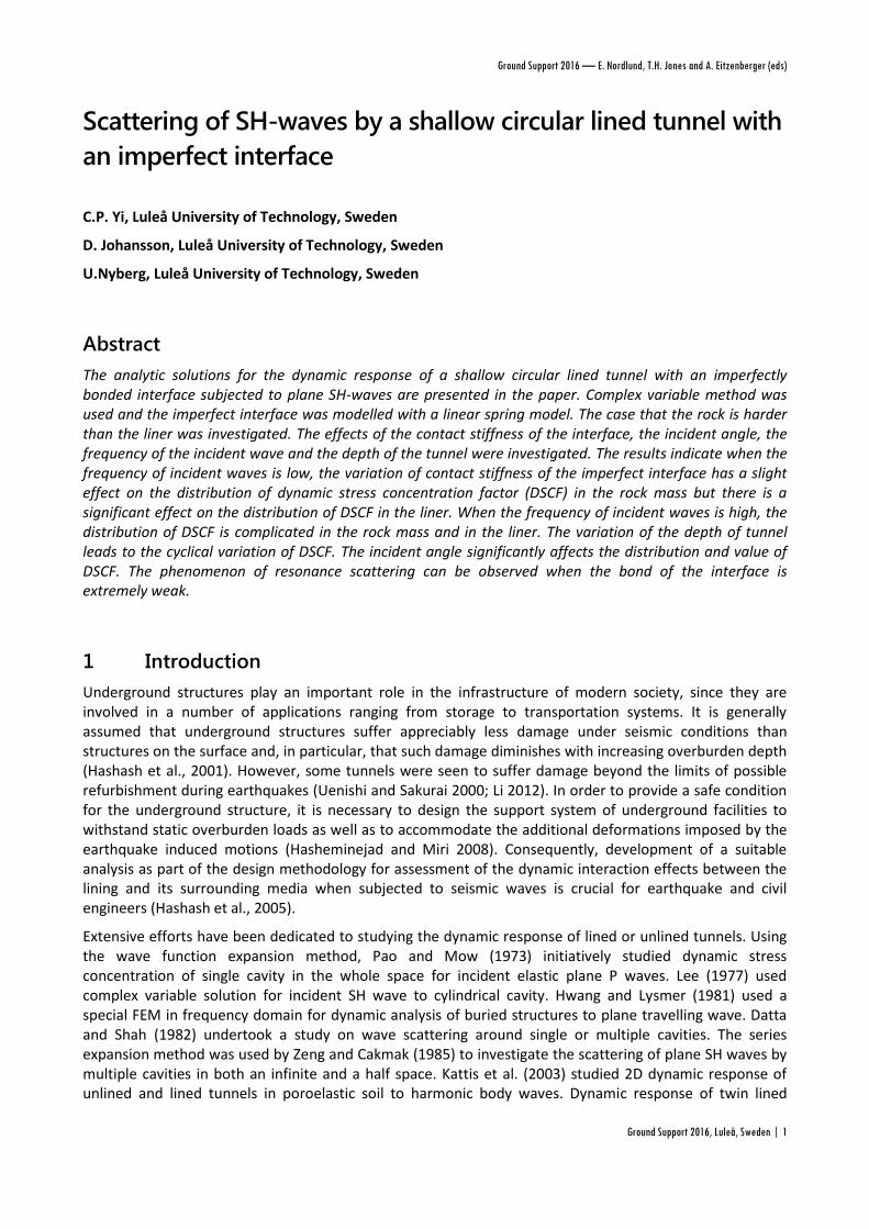
We consider an infinitely long lined circular tunnel of outer radius b and inner radius a in the rock mass. A
plane harmonic SH-wave propagates in the rock mass with incident angle of 0 and meets the lined tunnel,
see Figure.1. In complex plane ( z , z ),the incident SH-wave can be expressed as (Lin and Liu 2002)
1 0 02
[( ) ( ) ]( )
1 0
i ii z ih e z ih eiw w e
(7)
where ( )
1
iw is the incident SH-wave, 0w is the amplitude of the incident wave, 1 is the wave number of the
SH-wave in the rock mass. h is the distance OO1 in Figure 1.
h
a
b x
yx1
y1
o
o1
Figure 1 Problem geometry.
The corresponding stresses are expressed as
1 0 02
[( ) ( ) ]( )
1 0 0cos( )i i
i z ih e z ih ei
rz i e
(8)
1 0 02
[( ) ( ) ]( )
1 0 0sin( )i i
i z ih e z ih ei
z i e
(9)
where 0 1 1 0w is the maximum stress induced by SH-wave in the rock mass. 1 is the shear modulus of
the rock mass.
There is a reflected wave when the incident wave meets the ground surface. It can be written in the
complex plane ( z , z ) as

Scattering of SH-waves by a shallow circular lined tunnel with an imperfect interface C.P. Yi, D. Johansson, U.Nyberg
4 |Ground Support 2016, Luleå, Sweden
1 0 02
[( ) ( ) ]( )
1 0
i ii z ih e z ih erw w e
(10)
The corresponding stresses are
1 0 02
[( ) ( ) ]( )
1 0 0cos( )i i
i z ih e z ih er
rz i e
(11)
1 0 02
[( ) ( ) ]( )
1 0 0sin( )i i
i z ih e z ih er
z i e
(12)
There is a reflected wave from the interface when the incident wave meets the liner, it can be written in
the complex plane ( z , z )
( ) (1) (1)
1 1 1
2{ ( )[ ] ( 2 )[ ] }
2
s m m
m m m
m
z z hiw A H z H z hi
z z hi
(13)
where mA is an uncertain constants and (1)
mH is the Hankel function of the first kind for integer order m,
which represents an outward-propagating cylindrical wave.
The corresponding stresses are:
( ) (1) 1 (1) 11 11 1 1 1 1
(1) ( 1) (1) ( 1)
1 1 1 1
{ ( | |)[ ] ( | |)[ ]2
2 2[ ( | 2 |)[ ] ( | 2 |)[ ] ]}
2 2
s m i m i
rz m m m
m
m i m i
m m
z zA H z e H z e
z z
z hi z hiH z hi e H z hi e
z hi z hi
(14)
( ) (1) 1 (1) 11 11 1 1 1 1
(1) ( 1) (1) ( 1)
1 1 1 1
{ ( | |)[ ] ( | |)[ ]2
2 2[ ( | 2 |)[ ] ( | 2 |)[ ] ]}
2 2
s m i m i
z m m m
m
m i m i
m m
z zi A H z e H z e
z z
z hi z hiH z hi e H z hi e
z hi z hi
(15)
The total displacement field in the rock mass is
( ) ( ) ( ) ( )
1 1 1 1
T i r sw w w w (16)
The total stress field in the rock mass is
( ) ( ) (r) (s)
1 1 1 1
T i
rz rz rz rz (17)
( ) ( ) (r) (s)
1 1 1 1
T i
z z z z (18)
2.3 Waves in liner
There is an SH-wave ( ( )
2
tw ) that propagates to the inside of the liner from the outside boundary of liner. It
can be expressed as:
( ) (2)
2 2( | |)[ ]t m
m m
m
zw B H z
z
(19)
where mB is an uncertain constant and (2)
mH is the Hankel function of the second kind for integer order m,
which represents an inward-propagating cylindrical wave. 2 is the wave number of the SH-wave in the
liner.

Seismic/Dynamic Issues 2 - Support
Ground Support 2016, Luleå, Sweden | 5
The corresponding stresses are:
( ) (2) 1 (2) 12 22 1 2 1 2{ ( | |)[ ] ( | |)[ ] }
2
t m i m i
rz m m m
m
z zB H z e H k z e
z z
(20)
( ) (2) 1 (2) 12 2
2 1 2 1 2{ ( | |)[ ] ( | |)[ ]2
t m i m i
z m m m
m
z zi B H z e H z e
z z
(21)
where 2 is the shear modulus of the liner.
There is a reflected SH-wave in the liner which propagates outwards from the inside boundary of the liner. It can be expressed as
( ) (1)
2 2( | |)[ ]r m
m m
m
zw C H z
z
(22)
The corresponding stresses are:
( ) (1) 1 (1) 12 2
2 1 2 1 2{ ( | |)[ ] ( | |)[ ]2
r m i m i
rz m m m
m
z zC H z e H z e
z z
(23)
( ) (1) 1 (1) 12 2
2 1 2 1 2{ ( | |)[ ] ( | |)[ ]2
r m i m i
z m m m
m
z zi C H z e H z e
z z
(24)
The total displacement field and the stress field in the liner are
( ) ( ) ( )
2 2 2
T t rw w w (25)
( ) ( ) (r)
2 2 2
T t
rz rz rz (26)
( ) ( ) (r)
2 2 2
T t
z z z (27)
3 Boundary conditions
The support system such as liner usually is designed for underground facilities, where the liners generally are neither perfectly bonded to nor perfectly lubricated from the surrounding rock, i.e. the interface is usually an imperfect bonding. Several imperfect interface models were proposed (Jones and Whittier, 1967; Murty, 1975; Newmark et al., 1951; Paskaramoorthy et al., 1988; Rokhlin and Wang, 1991). The linear spring model (Newmark et al., 1951) adopted for this work is one of the popular models for modeling the imperfect interface (Achenbach and Zhu, 1989; Sudak et al., 1999; Shen et al., 2001; Valier-Brasier et al., 2012). The model assumes that tractions are continuous but displacements may be discontinuous across the interface. More precisely, jumps in the displacement components are assumed to be proportional to their respective interface traction components. These interface parameters are assumed to be uniform along the entire length of the interface and the interface model is said to represent a homogeneously imperfect interface. Using this concept, the boundary conditions to be applied at the interface of the liner and the rock mass can be described as:
11 2
rzz z
s
u uk
(28a)
1 2rz rz (28b)

Scattering of SH-waves by a shallow circular lined tunnel with an imperfect interface C.P. Yi, D. Johansson, U.Nyberg
6 |Ground Support 2016, Luleå, Sweden
2 0rz (29)
(11) (12) (13) (1)( )m m m m m m
m
A B C
(30)
Where:
(11) (1) (1)
1 1
(1) 1 (1) 11 11 1 1 1
(1) ( 1) (1) ( 1)
1 1 1 1
2( )[ ] ( 2 )[ ]
2
{ ( | |)[ ] ( | |)[ ]2
2 2[ ( | 2 |)[ ] ( | 2 |)[ ] ]}
2 2
m m
m m m
m i m i
m m
s
m i m i
m m
z z hiH z H z hi
z z hi
z zH z e H z e
k z z
z hi z hiH z hi e H z hi e
z hi z hi
where sk is tangential spring stiffness. The subscripts of 1 and 2 denote the components in the rock and the
liner, respectively.
At the inner boundary of the liner, the boundary condition can be expressed as:
Substituting eqs. (17), (18) and (25) into eq.(28a), we can get
where
(12) (2)
2( | |)[ ]m
m m
zH z
z
(13) (1)
2( | |)[ ]m
m m
zH z
z
1 10 0 0 02 2
1 10 0 0 02 2
[( ) ( ) ] [( ) ( ) ](1) 1 1 00 0
[( ) ( ) ] [( ) ( ) ]
0 0
{cos( ) cos( ) }i i i i
i i i i
i z ih e z ih e i z ih e z ih e
s
i z ih e z ih e i z ih e z ih e
i we e
k
w e w e
Substituting eqs. (17) and (26) into the second term of eq. (28b), we can get
(21) (22) (23) (2)( )m m m m m m
m
A B C
(31)
where
(21) (1) 1 (1) 11 11 1 1 1
(1) ( 1) (1) ( 1)
1 1 1 1
{ ( | |)[ ] ( | |)[ ]2
2 2[ ( | 2 |)[ ] ( | 2 |)[ ] ]}
2 2
m i m i
m m m
m i m i
m m
z zH z e H z e
z z
z hi z hiH z hi e H z hi e
z hi z hi
(22) (2) 1 (2) 12 21 2 1 2{ ( | |)[ ] ( | |)[ ] }
2
m i m i
m m m
z zH z e H z e
z z
(23) (1) 1 (1) 12 21 2 1 2{ ( | |)[ ] ( | |)[ ] }
2
m i m i
m m m
z zH z e H z e
z z

Seismic/Dynamic Issues 2 - Support
Ground Support 2016, Luleå, Sweden | 7
1 10 0 0 02 2
[( ) ( ) ] [( ) ( ) ](2)
1 1 0 0 0{cos( ) +cos( ) }i i i i
i z ih e z ih e i z ih e z ih ei w e e
According to Eq. (29), we can get
(32) (33)( ) 0m m m m
m
B C
(32)
where
(32) (2) 1 (2) 12 21 2 1 2{ ( | |)[ ] ( | |)[ ] }
2
m i m i
m m m
z zH z e H z e
z z
(33) (1) 1 (1) 12 21 2 1 2{ ( | |)[ ] ( | |)[ ] }
2
m i m i
m m m
z zH z e H z e
z z
Then, both sides of eqs. (30), (31) and (32) are multiplied by ine and integrated from –π to π. Thus, the problem is reduced to a series of equations as follows:
(11) (12) (13) (1)
(21) (22) (23) (2)
(32) (33)0 0
mn mn mn m n
mn mn mn m n
m
mn mn m
A
B
C
0, 1, 2,...n (33)
where
(11) (11)1
2
in
mn m e d
(12) (12)1
2
in
mn m e d
(13) (13)1
2
in
mn m e d
(1) (1)1
2
in
n e d
(21) (21)1
2
in
mn m e d
(22) (22)1
2
in
mn m e d
(23) (23)1
2
in
mn m e d
(2) (2)1
2
in
n e d
(32) (32)1
2
in
mn m e d
(33) (33)1
2
in
mn m e d
Therefore, the unknown coefficients of Am, Bm and Cm can be determined by solving eq. (33).
4 Numerical results and discussions
Dynamic effects on lined tunnels are in the form of stress concentrations or deformations that they experience when suffering dynamic loads. It is important to solve the DSCF in the tunnel and the liner under the incident SH-wave. For this problem the main task is to study the DSCF in the rock mass and the edge of
the liner. The DSCF z can be expressed as
0z z
(34)
To get a general solution, some dimensionless parameters are defined. We define that the ratio of the wave numbers of the liner and the rock and the ratio of the shear moduli of the rock and the
liner is . This case can be regarded as a concrete liner in rock. We define three spring stiffness
values 1 1 1 1 1 10.1 ,1.0 ,10.0sK to study the effect of imperfect interface. The ratio of outer radius to
inner radius of the liner /b a is 1.2.
2 1/ 1.5
1 2/ 2.9

Scattering of SH-waves by a shallow circular lined tunnel with an imperfect interface C.P. Yi, D. Johansson, U.Nyberg
8 |Ground Support 2016, Luleå, Sweden
4.1 Effect of imperfect interface
To investigate the effect of imperfect interface, the incident angle is set as 90°and the ratio of the depth of the tunnel and the inner radius of the liner h/a=1.5. The distributions of DSCF are shown in Figure 2. When the frequency of the incident wave is low, the maximum of DSCF is at around θ=210°and 330°in the rock and the liner, see Figure 2 (a) and Figure 2 (b). Increasing spring stiffness leads to slightly decreasing DSCF in the rock and increasing DSCF in the liner. When the frequency of the incident wave is high, the distribution of DSCF is complicated in both rock and liner, see Figure2 (c) and Figure 2 (d). Three different spring stiffness values lead to similar DSCF in the rock and much different DSCF in the liner. The comparison of Figure 2 (a) and Figure 2 (c) shows that the low frequency incident wave leads to smaller DSCF in the rock than the high frequency incident wave, which is different from the situation that the tunnel is in a whole space (Yi et al. 2014b). So the ground surface is another important factor for the distribution of DSCF.
0.00
0.25
0.50
0.75
0
30
60
90
120
150
180
210
240
270
300
330
0.00
0.25
0.50
0.75
h/a=1.5
1a=0.1
R=b
α0=90°
KS=10
1
KS=1.0
1
KS=0.1
1
0.0
0.1
0.2
0.3
0
30
60
90
120
150
180
210
240
270
300
330
0.0
0.1
0.2
0.3
h/a=1.5
1a=0.1
R=a
α0=90°
KS=10
1
KS=1.0
1
KS=0.1
1
(a) DSCF in the rock (b) DSCF in the liner
0.0
0.5
1.0
1.5
2.0
0
30
60
90
120
150
180
210
240
270
300
330
0.0
0.5
1.0
1.5
2.0
h/a=1.5
1a=2.0
R=b
α0=90°
KS=10
1
KS=1.0
1
KS=0.1
1
0.0
0.5
1.0
1.5
0
30
60
90
120
150
180
210
240
270
300
330
0.0
0.5
1.0
1.5
h/a=1.5
1a=2.0
R=a
α0=90°
KS=10
1
KS=1.0
1
KS=0.1
1
(c) DSCF in the rock (d) DSCF in the liner
Figure 2 DSCF in the rock and the liner with h/a=1.5 and 0 =90° (a) DSCF in the rock at r=b with low
frequency incident waves;(b) DSCF in the liner at r=a with low frequency incident waves; (c)
DSCF in the rock at r=b with high frequency incident waves; (d) DSCF in the liner at r=a with
high frequency incident waves
4.2 Effect of depth of tunnel
To investigate the effect of depth of the tunnel on the dynamic response of lined tunnel, only the ratio of the depth of the tunnel and the inner radius of the liner h/a is changed to 30 in this case compared to the case in section 4.1. The distributions of DSCF are shown in Figure 3. When the frequency of the incident wave is low, the maximum of DSCF is at around θ=30°and 150°in the rock and the liner, see Figure 3 (a) and Figure 3 (b), which is quite different from the low frequency case in section 4.1. When
1 10.1sK , the

Seismic/Dynamic Issues 2 - Support
Ground Support 2016, Luleå, Sweden | 9
contact between the rock mass and the liner is weak, which induces the DSCF in the liner is quite small compared to
1 11.0sK and1 110.0sK , see Figure 3 (b).
When the frequency of the incident wave is high, there are four peak values of DSCF in the rock and the liner, see Figure3 (c) and Figure 3 (d). The variation of spring stiffness has a slight effect on the distribution of DSCF in the rock, see Figure 3 (c). But in the liner,
1 11.0sK induces the largest DSCF while
1 10.1sK induces the smallest DSCF because of the weak contact.
Figure 4 shows the variation of DSCF at θ=0° with the depth change when 1 110.0sK and the incident
angle is 90°. The results indicate that the DSCF at θ=0° changes cyclically with the variation of the depth of the tunnel. The DSCF varies sharply for high frequency incident waves while it varies smoothly for low frequency incident waves.
0.0
0.5
1.0
0
30
60
90
120
150
180
210
240
270
300
330
0.0
0.5
1.0
h/a=30
1a=0.1
R=b
α0=90°
KS=10
1
KS=1.0
1
KS=0.1
1
0.0
0.1
0.2
0.3
0
30
60
90
120
150
180
210
240
270
300
330
0.0
0.1
0.2
0.3
h/a=30
1a=0.1
R=a
α0=90°
KS=10
1
KS=1.0
1
KS=0.1
1
(a) DSCF in the rock (b) DSCF in the liner
0
1
2
3
0
30
60
90
120
150
180
210
240
270
300
330
0
1
2
3
h/a=30
1a=2.0
R=b
α0=90°
KS=10
1
KS=1.0
1
KS=0.1
1
0.0
0.4
0.8
1.2
1.6
0
30
60
90
120
150
180
210
240
270
300
330
0.0
0.4
0.8
1.2
1.6
h/a=30
1a=2.0
R=a
α0=90°
KS=10
1
KS=1.0
1
KS=0.1
1
(c) DSCF in the rock (d) DSCF in the liner
Figure 3 DSCF in the rock and the liner with h/a=30.0 and 0 =90° (a) DSCF in the rock at r=b with low
frequency incident waves; (b) DSCF in the liner at r=a with low frequency incident waves; (c)
DSCF in the rock at r=b with high frequency incident waves; (d) DSCF in the liner at r=a with
high frequency incident waves

Scattering of SH-waves by a shallow circular lined tunnel with an imperfect interface C.P. Yi, D. Johansson, U.Nyberg
10 |Ground Support 2016, Luleå, Sweden
0 10 20 30 40 50 600.0
0.5
1.0
1.5
2.0
2.5
3.0
3.5
4.0
4.5
θ=0°
1a=0.1
1a=2.0
h/a
KS=10
1
DS
CF
α0=90°
R=b
0 10 20 30 40 50 60
0.0
0.5
1.0
1.5
2.0
1a=0.1
1a=2.0
h/a
KS=10
1
DS
CF
α0=90°
θ=0°R=a
(a) Variation of DSCF in the rock (b) Variation of DSCF in the liner
Figure 4 Variation of DSCF with the change of depth h/a (a) Variation of DSCF in the rock at r=b and
θ=0° (b) Variation of DSCF in the liner at r=a and θ=0°.
4.3 Effect of incident angle
To investigate the effect of depth of the tunnel on the dynamic response of lined tunnel, only the incident
angle 0 is changed to 45° in this case compared to the case in section 4.1. The distributions of DSCF are
shown in Figure 5. When the frequency of the incident wave is low, the maximum DSCF is at 90°in the rock and the liner, see Figure 5 (a) and Figure 5 (b). Increasing spring stiffness leads to slightly decreasing DSCF in the rock and increasing DSCF in the liner. By comparing Figure 5 (a) to Figure2 (a) and comparing Figure5 (b) to Figure2 (b), it can be observed that the maximum DSCF in both rock and liner for incident angle of 45°is much greater than that for the incident angle of 90°when h/a is 1.5 and the frequency of the incident wave is low, though the maximum DSCF is located at different positions due to different incident angle.
When the frequency of the incident wave is high, the distribution of DSCF is complicated both in the rock and the liner, see Figure5 (c) and Figure 5 (d). The variation of spring stiffness has a slight effect on the distribution of DSCF in the rock; see Figure 5 (c). But in the liner,
1 11.0sK induces the largest DSCF in
the liner while 1 10.1sK induces the smallest DSCF in the liner because of the weak contact.
Figure 6 shows the variation of DSCF at 90 with the frequency change and the contact stiffness change when the incident angle is 45°.
1 11.0sK and 1 110.0sK give similar DSCF variation curves with the
change of frequency for both rock and liner. When the bond is extremely imperfect (1 10.1sK ), the
results show that there are several peak values of DSCF in the rock and the liner, which is due to the resonance scattering as observed by Rajabi et al. (2009). This phenomenon is very unique for the case of the extremely imperfect interface (Wang and Sudak 2007).

Seismic/Dynamic Issues 2 - Support
Ground Support 2016, Luleå, Sweden | 11
0
1
2
3
4
5
0
30
60
90
120
150
180
210
240
270
300
330
0
1
2
3
4
5
h/a=1.5
1a=0.1
R=b
α0=45°
KS=10
1
KS=1.0
1
KS=0.1
1
0.0
0.5
1.0
1.5
0
30
60
90
120
150
180
210
240
270
300
330
0.0
0.5
1.0
1.5
h/a=1.5
1a=0.1
R=a
α0=45°
KS=10
1
KS=1.0
1
KS=0.1
1
(a) DSCF in the rock (b) DSCF in the liner
0
1
2
3
0
30
60
90
120
150
180
210
240
270
300
330
0
1
2
3
h/a=1.5
1a=2.0
R=b
α0=45°
KS=10
1
KS=1.0
1
KS=0.1
1
0
1
2
0
30
60
90
120
150
180
210
240
270
300
330
0
1
2
h/a=1.5
1a=2.0
R=a
α0=45°
KS=10
1
KS=1.0
1
KS=0.1
1
(c) DSCF in the rock (d) DSCF in the liner
Figure 5 DSCF in the rock and the liner with0 45 and h/a=1.5 (a) DSCF in the rock at r=b with low
frequency incident waves; (b) DSCF in the liner at r=a with low frequency incident waves; (c)
DSCF in the rock at r=b with high frequency incident waves; (d) DSCF in the liner at r=a with
high frequency incident waves.
0.0 0.5 1.0 1.5 2.00
1
2
3
4
5h/a=1.5
R=b
θ=90°
α0=45°
DS
CF
1a
KS=10
1
KS=1.0
1
KS=0.1
1
0.0 0.5 1.0 1.5 2.00
1
2
3
4
5
6
7
8h/a=1.5
R=a
θ=90°
α0=45°
DS
CF
1a
KS=10
1
KS=1.0
1
KS=0.1
1
(a) DSCF in the rock (b) DSCF in the liner
Figure 6 DSCF versus the frequency of incident wave with 0 45 (a) Variation of DSCF in the rock at
r=b and θ=90° (b) Variation of DSCF in the liner at r=a and θ=90°.

Scattering of SH-waves by a shallow circular lined tunnel with an imperfect interface C.P. Yi, D. Johansson, U.Nyberg
12 |Ground Support 2016, Luleå, Sweden
5 Conclusion
1. The dynamic response of a shallow lined tunnel with an imperfect interface under incident SH-waves was studied by using the complex variable method and the spring model for the imperfect interface. Some observations are as follows,
2. When the frequency of incident waves is low, the variation of contact stiffness has a slight effect on the distribution of dynamic stress concentration factor (DSCF) in the rock mass but there is a significant effect on the distribution of DSCF in the liner.
3. When the frequency of incident waves is high, the distribution of DSCF is complicated in the rock mass and the liner.
4. The variation of the depth of tunnel leads to the cyclical variation of DSCF. DSCF changes sharply when the frequency of incident waves is high while it changes smoothly when the frequency of incident waves is low.
5. The maximum DSCF in both rock and liner for incident angle of 45°is much greater than that for the incident angle of 90° when h/a is 1.5 and the frequency of the incident wave is low.
6. The phenomenon of resonance scattering can be observed when the bond of an interface is extremely weak.
References
Achenbach, J & Zhu, H 1989,´ Effect of interfacial zone on mechanical behavior and failure of fiber-reinforced composites`. Journal
of the Mechanics and Physics of Solids, vol.37, pp.381-393.
Datta, S.K & Shah, A.H 1982, ´ Scattering of SH-waves by embedded cavities. Wave Motion, vol. 4, pp.256-283.
Hashash, Y.M.A., Hook, J.J., Schmidt, B &Yao, J.I 2001, ´Seismic Design and Analysis of Underground Structures`, Tunneling and
Underground Space Technology. vol.16, pp. 247-293.
Hashash ,Y.M.A., Park, D & Yao J 2005, ´ Ovaling Deformations of Circular Tunnels Under Seismic Loading, an Update on Seismic
Design and Analysis of Underground Structures`. Tunneling, Underground Space Technology.vol. 20, pp. 435-441
Hasheminejad, S.M., Miri, A.K 2008, ´Seismic isolation effect of lined circular tunnels with damping treatments`. Earthquake engineering and engineering vibration, no.7,pp.305-319
Hwang, R.N & Lysmer, J 1981, ´ Response of buried structures to travelling waves`. J. Geotech. Eng. Div., ASCE, vol. 107, pp.183-200. Jones, J & Whittier, J 1967, ´Waves at a flexibly bonded interface`. Journal of Applied Mechanics, vol.34, pp.905-909. Kattis, S., Beskos, D., Cheng, A 2003, ´2D dynamic response of unlined and lined tunnels in poroelastic soil to harmonic body
waves`. Earthquake engineering & structural dynamics, vol. 32, pp.97-110. Lee, V.W &Trifunac, M.D 1979, ´Response of tunnels to incident SH-waves`. Journal of the Engineering Mechanics Division, vol. 105,
pp.643-659. Li, T. B 2012, ´Damage to mountain tunnels related to the Wenchuan earthquake and some suggestions for aseismic tunnel
construction`, Bulletin of Engineering Geology and the Environment, vol.71, no. 2, pp. 297–308.
Liang, J., Zhang, H & Lee, V. W 2003, ´A series solution for surface motion amplification due to underground twin tunnels: Incident
SV waves`. Earthquake Eng. Eng. Vib., vol.2,no.2,pp. 289–298.
Liang, J. W., Zhang, H & Lee, V. W 2004, ´Series solution for surface motion amplification due to underground group cavities: Incident P waves`. Acta Seismo. Sinica, vol.17,no.3, pp. 296-307.
Lin,H & Liu D 2002, ´Scattering of SH wave around a circular cavity in half space`. Earthquake Engineering and Engineering Vibration, vol.22,no.2,pp. 9-16 (in Chinese)
Liu, Q, Zhao, M & Wang, L 2013, ´Scattering of plane P, SV or Rayleigh waves by a shallow lined tunnel in an elastic half space`. Soil
Dynamics and Earthquake Engineering, 49: 52–63.
Martin, P 1992, ´Boundary integral equations for the scattering of elastic waves by elastic inclusions with thin interface layers`. Journal of nondestructive evaluation ,v.11, p.167-174.
Moore, I.D & Guan, F 1996, ´Three-dimensional dynamic response of lined tunnels due to incident seismic waves`. Earthquake engineering & structural dynamics,vol. 25, pp.357-369.
Murty, G.S 1975, ´A theoretical model for the attenuation and dispersion of Stoneley waves at the loosely bonded interface of elastic half spaces. Physics of the Earth and Planetary Interiors,vol. 11,p p.65-79.
Newmark, N.M., Siess, C.P & Viest, I 1951, ´Tests and analysis of composite beams with incomplete interaction`. Proc. Soc. Exp. Stress Anal, vol.9, pp.75-92.
Pao, Y.H & Mow, C.C 1973, ´Diffraction of Elastic Waves and Dynamic Stress Concentrations`, Crane, Russak & Co. Inc, New York. 694p.

Seismic/Dynamic Issues 2 - Support
Ground Support 2016, Luleå, Sweden | 13
Paskaramoorthy, R., Datta, S & Shah, A 1988, ´Effect of interface layers on scattering of elastic waves`. Journal of applied mechanics, vol. 55, pp.871-878.
Qi, H, Wang, Y & Liu, D.K 2003,´Dynamic analysis of shallow-embedded lining structure by incident SH-wave `. Earthquake Engineering and Engineering Vibration, vol. 23, no. 3, pp.41-46 (in Chinese)
Rajabi, M & Hasheminejad, S.M 2009, ´Acoustic resonance scattering from a multilayered cylindrical shell with imperfect bonding `. Ultrasonics,vol.49, pp.682-695.
Rokhlin, S., Wang, Y., 1991, ´ Analysis of boundary conditions for elastic wave interaction with an interface between two solids `. The Journal of the Acoustical Society of America,vol. 89, pp.503-515.
Shen, H., Schiavone, P., Ru, C., Mioduchowski, A., 2001, ´ Stress analysis of an elliptic inclusion with imperfect interface in plane elasticity `. Journal of elasticity and the physical science of solids ,vol.62, pp.25-46.
Sudak, L., Ru, C., Schiavone, P., Mioduchowski, A., 1999, ´A circular inclusion with inhomogeneously imperfect interface in plane elasticity `. Journal of elasticity, vol.55, pp.19-41.
Uenishi, K & Sakurai, S. 2000, ´Characteristic of the vertical seismic waves associated with the 1995 Hyogo-ken Nanbu (Kobe), Japan
earthquake estimated from the failure of the Daikai Underground Station`. Earthquake Eng. Struct. Dyn. vol.29, pp. 813–
821.
Valier-Brasier, T., Dehoux, T & Audoin, B 2012, ´Scaled behavior of interface waves at an imperfect solid-solid interface `. Journal of Applied Physics,vol.112, pp.024904-024912.
Wang, X., Sudak, L., 2007, ´Scattering of elastic waves by multiple elastic circular cylinders with imperfect interface`. Waves in Random and Complex Media, vol.17, pp.159-187.
Yi, C., Zhang, P., Johansson, D. & Nyberg, U 2014a, ´Dynamic response of a circular lined tunnel with an imperfect interface subjected to cylindrical P-waves `. Computers and Geotechnics. vol. 44, pp. 165–171.
Yi, C., Zhang, P., Johansson, D. & Nyberg, U 2014b, ´Dynamic analysis for a circular lined tunnel with an imperfectly bonded interface impacted by plane SH-waves `. World Tunnel Congress. Iguassu Falls, Brazil.
Zeng, X., and Cakmak, A. S. 1985, ´Scattering of plane SH-waves by multiple cavities `. Press. Vess. Pip. Div. Pub. PVP, vol.98, pp. 155–163.