scanfont 5 for macintosh user manual - font-software, schrift
TRANSCRIPT
ScanFont 5 for Macintosh®
User Manual

ScanFont 5 user manual, edition 5.0 [1.11.2007]
Copyright © 1992–2007 by Fontlab Ltd. All rights reserved.
Editors: Sasha Petrov, Adam Twardoch, Ted Harrison, Yuri Yarmola
Cover illustration: Paweł Jońca, pejot.com
No part of this publication may be reproduced, stored in a retrieval system, or transmitted, in any form or by any means, electronic, mechanical, photocopying, recording, or otherwise, without the prior written consent of the publisher. Any software referred to herein is furnished under license and may only be used or copied in accordance with the terms of such license.
AsiaFont Studio, BitFonter, CompoCompiler, FONmaker, FogLamp, FontFlasher, FontLab, ScanFont, SigMaker, TransType, TypeTool, FontAudit, VectorPaint and the FontLab logo are either registered trademarks or trademarks of Fontlab Ltd. in the United States and/or other countries.
Apple, the Apple Logo, Mac, Mac OS, Macintosh and TrueType are trademarks of Apple Computer, Inc., registered in the United States and other countries.
Adobe, PostScript, Photoshop, Type Manager, Illustrator, Macromedia, Fontographer, Flash and Freehand are trademarks of Adobe Systems Incorporated, which may be registered in certain jurisdictions.
OpenType, Windows, Windows 95, Windows 98, Windows XP and Windows NT are either registered trademarks or trademarks of Microsoft Corporation in the United States and/or other countries.
IBM is a registered trademark of International Business Machines Corporation.
Other brand or product names are the trademarks or registered trademarks of their respective holders.
THIS PUBLICATION AND THE INFORMATION HEREIN IS FURNISHED AS IS, IS SUBJECT TO CHANGE WITHOUT NOTICE, AND SHOULD NOT BE CONSTRUED AS A COMMITMENT BY FONTLAB LTD.
FONTLAB LTD. ASSUMES NO RESPONSIBILITY OR LIABILITY FOR ANY ERRORS OR INACCURACIES, MAKES NO WARRANTY OF ANY KIND (EXPRESS, IMPLIED OR STATUTORY) WITH RESPECT TO THIS PUBLICATION, AND EXPRESSLY DISCLAIMS ANY AND ALL WARRANTIES OF MERCHANTABILITY, FITNESS FOR PARTICULAR PURPOSES AND NONINFRINGEMENT OF THIRD PARTY RIGHTS.
This document was created by Fontlab Ltd (http://www.fontlab.com/).

Contents
CONTENTS 3
INTRODUCTION 7 About this Manual 8 System Requirements 9 Getting Started 10
PREPARING IMAGES 11 Scanning an Image 12
Preparation of the Source Image 13 Placing Paper with an Image into the Scanner 15 Scanning an Image 16
Importing an Image 17 Importing EPS 19 Importing an Image from the Clipboard 20 Creating an Empty Image 22
BASIC IMAGE EDITING 23 Changing Image Colors 24 Changing Image Size 26 Basic Tools 28
Select Tool 29 Moving a Selection 30 Copying and Pasting a Selection 30 Brush Tool 31 Rectangle and Ellipse Tools 36 Zoom Tool 37
Basic Operations 38 Scale 39 Rotate 40

4
ScanFont 5
Rotate 90°CW, Rotate 180° and Rotate 90°CCW 41 Removing Background 42 Brightness/Contrast 44
SPLITTING AN IMAGE 45 Autosplitting Algorithms 46 Customizing Autosplit 49 Editing Splitting Data 51 Saving and Restoring Splitting Data 55 Defining the Scale Factor 56 Editing Baselines 59 Other Cell Commands 62
CREATING CHARACTERS 64 Outline Font Editor 65 Placing Characters into a Font 66 Tracing Options 69
Easy Trace Options 71 Advanced Trace Options 72
ADVANCED IMAGE EDITING 73 The Image Window 74
Image Window Contents 75 View Menu 80 Info Panel 82 Context Menu 84
Tools 85 Selecting 86 Operations on a Selection 91 Drawing 94 Other Tools 105
Operations 106 Flip Horizontal and Flip Vertical 107 Slant 108 Make Bold 109 Shift 110 Clear Bitmap 110 Brightness/Contrast 110 Hue/Saturation 111 Threshold 112 Invert 114

5
Contents
Colorize 115 Removing Background 117 Emboss 118 Smart Blur 119 Gaussian Blur 120 Enhance 121 Reduce Noise 122 Median Noise 123 Sharpen 124 Soften 125 Custom Filter 126 Find Edges 128 Outline Operations 129
SCANFONT USER INTERFACE 131 Basic Terms 132
Character 132 Glyph 133 Font 133 Encoding 134 Some More Definitions 135
Customizing ScanFont’s User Interface 137 Customization of the Keyboard 138
ScanFont Options 141 General Options 143 Image Window Options 144 Image To Font Conversion 146 Outline Font Editor 147
INDEX 149


Introduction
ScanFont is a powerful add-on to FontLab Studio, AsiaFont Studio or TypeTool for turning digital images into professional looking technically correct outline fonts in minutes.
ScanFont allows you to scan or draw font characters and export them to an outline font editor for further editing. Click the mouse button a few times and you're done!
ScanFont includes a very precise autotracing algorithm that is designed to work with characters, so you can transform everything that you can print on paper or see on the computer screen into high-quality outlines and transfer them to FontLab Studio, AFS or TypeTool which can export Type 1, TrueType or OpenType fonts.
The key features of ScanFont 5 are:
High-quality fully customizable autotracing algorithm especially designed to handle characters
Automatic detection of glyphs and strings in a source image Support of almost all bitmap image formats, black-white or color Support of vector EPS format. High quality EPS import Integrated full-color bitmap editor with more than 15 tools and 20
filters Free-hand drawing tools with digitizing tablet support Export of outlines to an outline font editor or FontLab vfb format 100+ levels of undo/redo Easy-to-use customizable interface

8
ScanFont 5
About this Manual
This manual covers the Macintosh version of ScanFont 5.
The following chapters describe all of ScanFont’s features in full detail. They are organized to cover all the functions in their usual sequence.
Preparing Images
This chapter will help you reduce the time needed to get quality results with ScanFont by showing you how to properly prepare a source image for scanning. It also describes all the possible methods of importing an image into ScanFont.
Basic Image Editing
If a source image needs editing (automatic or manual), this chapter gives you some basic tips and examples.
Splitting an Image
After your image is imported and edited, it is then time to divide it into individual characters. Usually ScanFont does this automatically, but if manual editing is needed this chapter will help you.
Creating Characters
This chapter explains how to create characters from the prepared and separated image and export their outlines to an outline font-editing application.
Advanced Image Editing
This chapter describes all image-editing tools and operations in details and gives a description of all the editing windows and panels.
ScanFont User Interface
This chapter covers the basic definitions of the ScanFont user interface and its customization. All ScanFont options are discussed here as well.

9
Introduction
System Requirements
The Macintosh version of ScanFont requires one of the following hardware and software configurations:
A Power PC or Intel based Macintosh with Mac OS X v 10.3 or later installed (v 10.4 is recommended).
At least 15Mb of free space on the hard disk drive and at least 64 MB RAM.
10
ScanFont 5
Getting Started
Using ScanFont is not very tricky. The process of converting an image to a font is as follows:
1. Prepare the source image with image-editing applications or scan it from within ScanFont. Refer to the Preparing Images chapter for details.
2. Edit the image with ScanFont.
3. Autosplit the image.
4. Manually correct the autosplitting results.
5. Trace the bitmaps and transfer the outlines into a font opened in an outline font-editing application.
Preparing Images
In this chapter, we will discuss the preparation of source images. Later, we will talk about editing images, locating glyphs in an image and converting the glyphs' images into outline characters.
In ScanFont you can use the following sources of images:
An image of a font or of individual glyphs printed or written on paper and placed in a scanner
An image file in TIFF, PICT, PNG, BMP, GIF or JPEG format An image file in vector EPS format An image in a format supported by ScanFont (.sfd, .sf) The Macintosh Clipboard The ScanFont bitmap editor window — where you can draw directly in
ScanFont
The easiest way to get an image into ScanFont is to have a scanner connected to your computer.
Place the paper with the image into the scanner and scan it using ScanFont. ScanFont supports the TWAIN interface, so it can work with almost all scanners. (Refer to your scanner’s documentation to see whether it will work with the TWAIN interface.) If your scanner cannot work through TWAIN, you can use the program that comes with your scanner to scan the image and save it into one of the formats that ScanFont can read.
If you can place the image onto the Clipboard (using the Copy command in any image-editing application), you can get it from there and paste it into ScanFont as a new image.
If you do not have a prepared font image, but are ready to create it using the mouse or a digitizing tablet, you can start from a clear image and draw it using ScanFont’s image-editing tools.

12
ScanFont 5
Scanning an Image
There are several steps that you must perform to prepare and scan your image. The scanning stage is very critical for the quality of the resulting characters in the font, so please read this section carefully and take the time to experiment with your scanner and adjust the scanning sequence for the best results.
13
Preparing Images
Preparation of the Source Image To get best results we recommend that you prepare a source image (on paper) with the following characteristics in mind:
The paper must be white and smooth. The images of characters or symbols that you want to place into a font
must be large. The real size of the symbols that you want to scan depends on the optical resolution of your scanner. We recommend that the size of the symbols be at least 0.5 inch/1.25 cm in height. If you want to get a very precise result, you can prepare bigger characters, even one huge character on a page. ScanFont can process such a character, but our experiments have shown that characters bigger than mentioned above do not really improve the quality of the resulting outlines.
If you want to scan your signature, write it as usual. The more natural it is, the better the result.
If you are preparing a font of your handwriting, do not choose a thin pen. A standard 0.7mm pen is best.
Never use a pencil! The image will look contrasted on paper, but not when scanned. As a result you will get noise in the black areas of the image and holes in the characters' strokes.
If you are creating a handwriting font, try to align the characters on a baseline. You can use a light-yellow pen to draw lines before you write characters. Low contrast yellow lines will not show up in a scanned image, but they will help you to align characters properly.
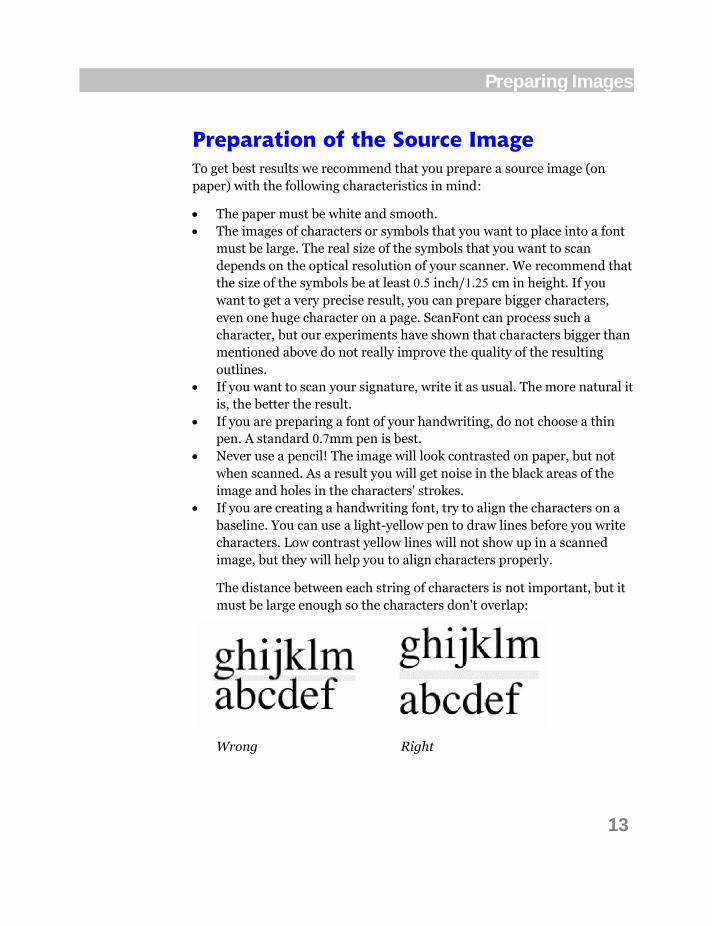
The distance between each string of characters is not important, but it must be large enough so the characters don't overlap:
Wrong Right

14
ScanFont 5
If you are not sure which shape of a character is best, write several versions, and then scan. Later, in ScanFont, you can select the best version. It is much better to have several versions of a symbol on one paper than to make an additional scan, because even if the scanner settings are the same, the position of the paper in the scanner will differ, so the result will be different.
Do not overlap characters. ScanFont includes advanced algorithms that can separate characters of any form, but not when characters "touch" each other. In ScanFont, overlapping or touching characters are treated as just one character in a strange format. Manual separation of overlapping characters is possible, but is very time-consuming.
Here is what we mean by "touching" and "overlapping" characters:
Wrong Right

15
Preparing Images
Placing Paper with an Image into the Scanner If you have a flatbed scanner, place the paper with the image into the scanner. If you have a hand-held scanner, prepare it for scanning. We do not recommend that you use hand-held scanners to prepare typographical fonts for ScanFont, because this type of scanner is not precise enough. But, if you are just adding your signature to an existing font or creating a handwritten or pictorial font, a hand-held scanner is adequate.
It is very important to put the paper straight on the scanner. The rotation of paper placed into a scanner, (even if only few degrees) dramatically decreases the quality of the results you will get in ScanFont. Try several times to make sure that the paper is aligned straight in the scanner.

16
ScanFont 5
Scanning an Image To scan a paper-based image in ScanFont:
1. Select the Select Source command in the File > Import menu.
2. Select the scanner in the dialog box that appears.
3. Prepare the image according to the recommendations in the Preparation of the Source Image section on page 13.
4. Switch the scanner on.
5. Select the Acquire command in the File > Import menu.
6. Follow the scanner-dependent scanning dialog to scan the image.
We recommend that you select 600 dpi as the default scanning resolution. If you scan a small picture, increase the scanning resolution, if the source picture is big (more than 1 inch in height), 300-400 dpi will be enough.
We also recommend that you scan the source picture in grayscale mode even when it appears black & white. This method allows you to get smoother glyph edges that will help create smooth outlines later. If you used light-yellow lines to align characters properly on paper, you should scan in color RGB mode.
Do not choose a resolution that is higher than the optical resolution of your scanner. Some scanner software lets you choose a resolution that is several times higher than the real optical scanning resolution of your scanner. The scanning software generates additional information necessary to “fill” the increased resolution automatically. For ScanFont's purposes, this is not necessary and can significantly decrease the quality of the resulting outlines.

17
Preparing Images
Importing an Image
If you have scanned your image or prepared it with an image editing application, you must save it in a format that ScanFont can open.
ScanFont supports black & white and color images in TIFF, PICT, JPEG, BMP, GIF or PNG format. Additional formats supported by QuickTime are also available.
You can control whether ScanFont will use internal import procedures or if it will ask QuickTime to do the job. Use the popup menu on the General page of the Preferences dialog box:
Choose the Never use QuickTime converters option to prohibit ScanFont using QuickTime on import, or choose the Always use QuickTime converters option to prohibit the internal ScanFont procedures. The default option, Use internal PNG/TIFF converters, allows ScanFont to use its own procedures for these particular formats and to ask QuickTime to open files in other formats.
To open an image in ScanFont:
1. Select the Open command in the File menu or click on the Open button on the Workflow toolbar:
2. In the standard File Open dialog open the folder and select the file that you want to open and click on the Open button. You can also drag-and-drop the icon of the image file onto the ScanFont main window.
18
ScanFont 5
You can open several images each in their own window. The number of open images is limited only by the memory allocated to the program.
Tip: When you open an image file the file name will appear in the bottom part of the File menu. Later, you can easily open this image again by simply selecting this file name in the menu.
Note: ScanFont has certain limits for the size of the image. The image width cannot exceed 32 Kb. This means true color images (with millions of colors) cannot be wider than 8191 pixels, images with thousands of colors cannot be wider than 16383 pixels, images with 256 colors or grays cannot be wider than 32 K pixels, etc.
19
Preparing Images
Importing EPS
ScanFont can import images in outline (“vector”) EPS format. This very important feature of ScanFont allows you to quickly convert images drawn in your favorite vector editor into a high quality outline font. You can save outline images from Adobe Illustrator, Macromedia FreeHand or other vector editors and then use ScanFont to easily transfer outlines to FontLab Studio, AsiaFont Studio or TypeTool for further processing. The image autotracing step may be skipped in this case.
Sometimes you may need to change the default options for output in the source application’s preferences dialog. For example, in Illustrator you should switch on the AICB option in the Options/Files&Clipboard settings.
To import an EPS file into ScanFont:
1. Select the Open command in the File menu.
2. In the Open File dialog box that appears, select the .eps file that you want to open and click on Open.
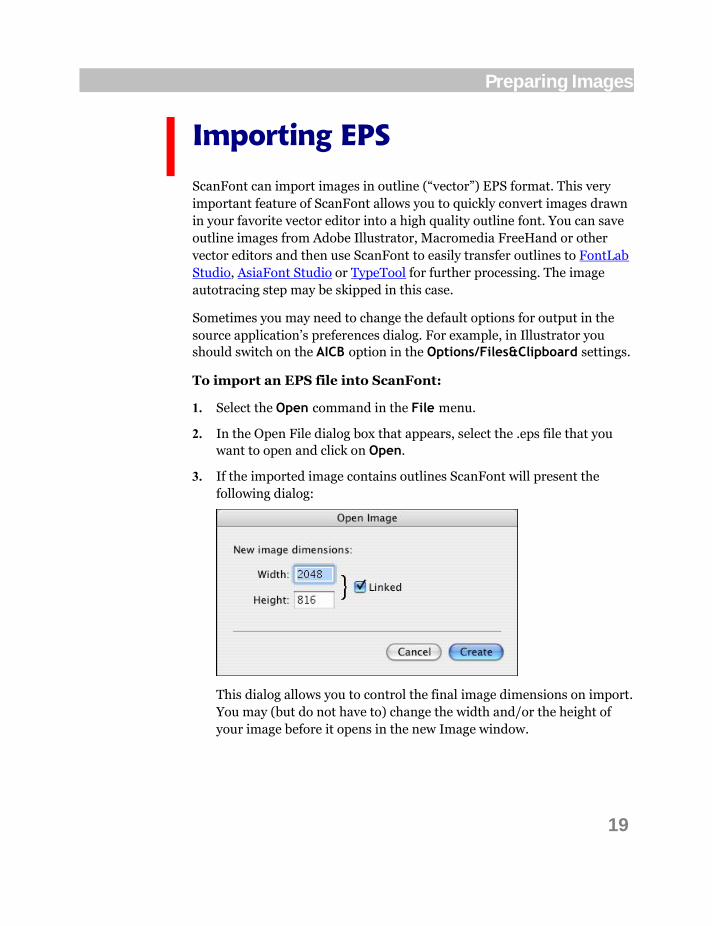
3. If the imported image contains outlines ScanFont will present the following dialog:
This dialog allows you to control the final image dimensions on import. You may (but do not have to) change the width and/or the height of your image before it opens in the new Image window.

20
ScanFont 5
Importing an Image from the Clipboard
Various programs that deal with bitmap images can exchange information by using the Clipboard. If you select and copy an image from such a program, it can be imported into ScanFont. As with image files, ScanFont can import either black & white or color images through the Clipboard.
Importing the Clipboard’s contents into ScanFont:
1. Run your image-editing application, open and select the image that you want to import into ScanFont and Copy it onto the Clipboard.
2. Switch to ScanFont and select the New command from the File menu. You will see the following dialog box:

21
Preparing Images
4. Check that the Create new image using Clipboard’s contents check box is switched on. If this option is not enabled, it means that you do not have a proper image in the Clipboard.
In the New Image section, you will see the size of the image that ScanFont will read from the Clipboard. If you want you can change the image dimensions to resample the imported image.
In the Color Mode dropdown list select Black & White, Grayscale or Color to change color information for the image. Select the number of colors as well.
5. Click on the OK button and you will see a new Image window with the Clipboard contents.
22
ScanFont 5
Creating an Empty Image
Sometimes you may not have an image ready, only an idea. You can create an image right in ScanFont, using bitmap-editing tools that are of the same quality as in the most well known image-editing programs. But first you have to create an empty image window.
To create an empty image:
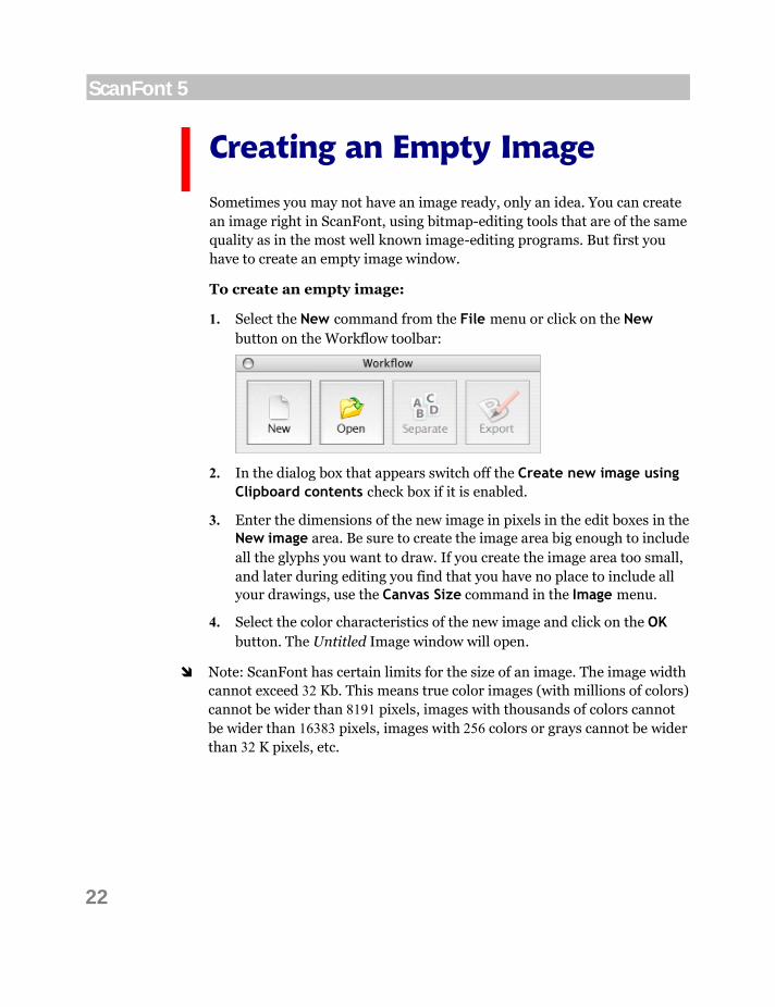
1. Select the New command from the File menu or click on the New button on the Workflow toolbar:
2. In the dialog box that appears switch off the Create new image using Clipboard contents check box if it is enabled.
3. Enter the dimensions of the new image in pixels in the edit boxes in the New image area. Be sure to create the image area big enough to include all the glyphs you want to draw. If you create the image area too small, and later during editing you find that you have no place to include all your drawings, use the Canvas Size command in the Image menu.
4. Select the color characteristics of the new image and click on the OK button. The Untitled Image window will open.
Note: ScanFont has certain limits for the size of an image. The image width cannot exceed 32 Kb. This means true color images (with millions of colors) cannot be wider than 8191 pixels, images with thousands of colors cannot be wider than 16383 pixels, images with 256 colors or grays cannot be wider than 32 K pixels, etc.

Basic Image Editing
When you create glyphs by importing images, you may want to edit them to get the best result. Or you may want to draw all font glyphs from scratch.
ScanFont includes professional bitmap-editing tools and operations for this purpose. We will discuss the complete set of editing tools and operations later in the Advanced Image Editing chapter on page 73. The most basic ones are introduced here in this chapter.

24
ScanFont 5
Changing Image Colors
While the Image window is open you can change the image color mode, i.e. the number of available colors.
Select the Color Mode command in the Image menu and you will see the Change Color Mode dialog:
Select a new Color Mode, Number of Colors and Color Table for the image you are editing in the corresponding dropdown lists.
You may want ScanFont to generate a custom color table for your image. This is possible in 4, 16 and 256 color modes only when you change the number of colors in the image. Select one of the available Adaptive color tables:

25
Basic Image Editing
If you are going to make a black & white image from a color or grayscale image, you must define the threshold parameter for conversion:
See the description of this parameter in the Threshold section.
You can view the preview of the image in the preview field of the dialog box. To see the original image sample, simply press and hold down the CTRL key.
Click on the OK button to finish the operation, or Cancel to leave the image color mode unchanged.
You can undo this operation using the Edit > Undo command.

26
ScanFont 5
Changing Image Size
Sometimes you may need to change the size of your image. You can do this in two ways.
The first way is to scale the image:
1. Select the Image Size command in the Image menu. The Image Size dialog will appear:
2. Enter the new image Width and Height in pixels. If the Proportional option is checked, the Height will be updated while you enter the Width and vice versa.
3. There are several predefined methods for scaling images included in the Resample dropdown list. If any choice other than the Simple resampling method is selected, you can tune it up with the slider to get the best result for your particular image. Note that what is good for one image will not necessarily be good for another.
4. Click on the OK button to scale the image, or click on Cancel to abort.

27
Basic Image Editing
The second way to resize an image is adding or removing workspace around the image:
1. Select the Canvas Size command in the Image menu. The Canvas Size dialog will appear:
2. Enter the new image Width and Height in pixels. If the Proportional option is checked, the Height will be updated while you enter the Width and vice versa.
3. For Anchor, click on a square to indicate where to position the existing image on the new canvas.
4. Click on the OK button to scale the image, or Cancel to abort.
You can undo both operations using the Edit > Undo command.
Note: If the image was separated into cells the separation information will be lost when resizing the image.
28
ScanFont 5
Basic Tools
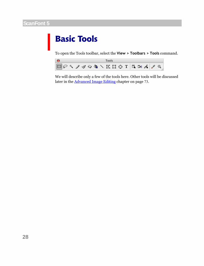
To open the Tools toolbar, select the View > Toolbars > Tools command.
We will describe only a few of the tools here. Other tools will be discussed later in the Advanced Image Editing chapter on page 73.
29
Basic Image Editing
Select Tool Use the Select tool to outline a rectangular area and display it with a grid.
To select a rectangular part:
1. Choose the Select tool in the Tools toolbar.
2. Put the mouse cursor on one of the corners of the rectangle that you want to select.
3. Hold down the mouse button and move the mouse cursor to the opposite corner of the area that you want to select.
4. Release the mouse button.
Tip: To temporarily switch to the Select tool while another tool is active, hold down the COMMAND key on the keyboard.
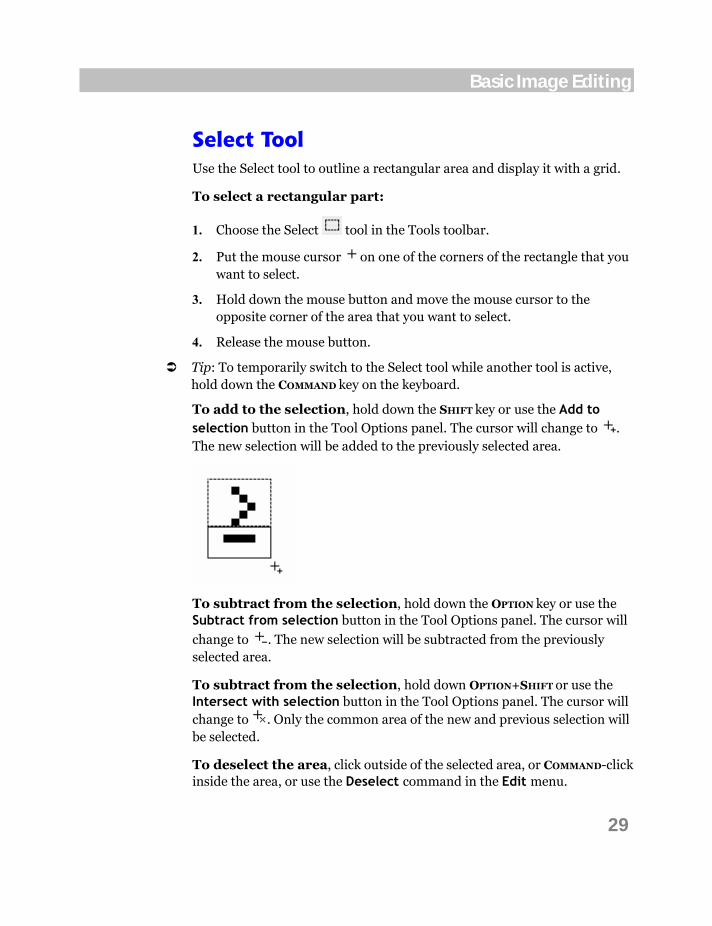
To add to the selection, hold down the SHIFT key or use the Add to selection button in the Tool Options panel. The cursor will change to . The new selection will be added to the previously selected area.
To subtract from the selection, hold down the OPTION key or use the Subtract from selection button in the Tool Options panel. The cursor will
change to . The new selection will be subtracted from the previously selected area.
To subtract from the selection, hold down OPTION+SHIFT or use the Intersect with selection button in the Tool Options panel. The cursor will change to . Only the common area of the new and previous selection will be selected.
To deselect the area, click outside of the selected area, or COMMAND-click inside the area, or use the Deselect command in the Edit menu.

30
ScanFont 5
Moving a Selection To move a selected area:
1. Choose a selection tool (Select, Select Region or Magic Wand).
2. Move the mouse cursor inside the selection area.
3. Hold down the mouse button and drag the selection to the new place.
4. Release the mouse button to finish moving or press the ESC key on the keyboard to abort the operation.
To constrain movement to the horizontal or vertical direction, hold down the SHIFT key after pressing the mouse button, and drag the mouse.
You can move the selected area by one pixel using the ARROW keys.
Copying and Pasting a Selection To copy a selection into another application or into another image, use the Copy and Paste commands from the Edit menu.
With the Copy command you can place a copy of the selection area onto the Clipboard, making it available to any application that can read bitmap images.
The Paste command reads bitmap images from the Clipboard and places them into the current editing field.
The Cut command combines Copy and Delete operations, so a copy of the selection is placed on the Clipboard, but the selection is deleted.

31
Basic Image Editing
Brush Tool The Brush is a wide version of pencil and is used for drawing. You select the brush shape in the Brushes panel:
Diameter is the brush shape diameter in pixels. The greater the value the wider the brush shape will be.
Hardness is the degree of diffusion of the brush edges. The greater the value the more diffused the brush edges will be. This option obviously does nothing in a plain black & white image.
Roundness is the form of the brush shape. If the roundness is zero, the brush is rectangular. The higher the value the rounder the brush. Here are examples of brushes of different roundness:

32
ScanFont 5
Angle defines the angle of the brush tip. It is applicable only to non-round brushes. If the angle is zero, the brush shape is horizontal. A positive angle turns the brush shape clockwise. A negative value turns the brush shape counter-clockwise. Here are examples of different brush angles:
Changing the Roundness and the Angle you can get calligraphic brushes of different shapes.
To use the Brush tool:
1. Select the Brush tool in the Tools toolbar and a color in the palette.
2. Set the brush diameter, roundness, angle and hardness in the Brushes panel.
3. Draw brush strokes by clicking on and dragging the mouse.
4. If you want to cancel a stroke while drawing, press the ESC key while dragging the mouse.
Tip: To draw a straight line with the Brush, click once at the line beginning and then SHIFT-click on at the line end.

33
Basic Image Editing
Brushes Panel
You can define several different brushes and place them in the Brushes panel. To make the Brushes panel visible, select the Brushes Panel command in the View menu:

34
ScanFont 5
To add a new brush to the top of the Brushes panel, define the brush’s
shape at the bottom and click on the button in the panel. The new brush will be added to the brushes list.
To remove a brush from the Brushes panel, click on the brush in the list
to select it and then click on the button in the panel. The brush shape will be deleted from the brushes list.
To change the shape of a brush in the Brushes panel, click on the brush in the list to select it; define the brush’s shape at the bottom; and
then click on the button in the panel. The new parameters will be applied to the currently selected brush.

35
Basic Image Editing
Tablet Options
If you have a digitizing tablet connected to your PC, you may need to set up
the tablet options. Click on the button in the Tool Options panel to bring up the following Tablet Options dialog:
You can customize the behavior of your digital pen in this dialog. Check Size, Hardness and Opacity options in an appropriate combination to define the results of pressing the digital pen.

36
ScanFont 5
Rectangle and Ellipse Tools These two tools are very similar in usage, but differ in result. The Rectangle tool is used to draw rectangles and squares, and the Ellipse tool draws ellipses and circles.
To draw a rectangle or an ellipse:
1. Select the appropriate tool, or , in the Tools toolbar and a color in the palette.
2. Position the mouse cursor on one of the rectangle’s corners. If you are drawing an ellipse, position the cursor on one of the corners of the imaginary rectangle that surrounds the ellipse.
3. Hold down the mouse button and drag the mouse to draw a rectangle or an ellipse.
4. Hold down the SHIFT key while drawing to draw a square instead of a rectangle, or a circle instead of an ellipse.
5. Hold down the OPTION key while dragging to place the center of the ellipse or rectangle at the place where you initially positioned the mouse cursor:
or
Pressing the OPTION key before you press the mouse button will change the tool temporarily to the Eye Dropper tool.
6. Release the mouse button to finish drawing or press the ESC key to abort.
The ellipse or rectangle will be filled with the current color if the Fill interior check box in the Tool Options panel is checked. To temporarily change the fill mode, hold down the CTRL key before releasing the mouse button.
37
Basic Image Editing
Zoom Tool Often the size of the image that you are editing is larger than the size of the window. You may need to see more details of an image. Do this by using the Zoom-in and Zoom-out buttons in the Image window or the Zoom tool.
To change the zoom mode:
1. Select the Zoom tool in the Tools toolbar.
2. Position the mouse cursor (or by holding down the OPTION key) on one of the corners of the image region that you want to zoom in on (or zoom out).
3. Hold down the mouse button and move the mouse to select the region.
4. Release the mouse button. The new zoom mode will be selected.
To change the zoom mode by one level, simply click (or OPTION -click) somewhere in the editing field.
To get the Zoom tool temporarily while another tool is selected, hold down COMMAND+SPACEBAR or COMMAND+OPTION+SPACEBAR.
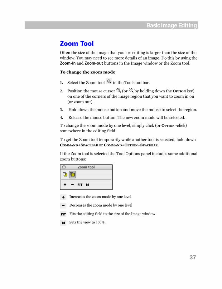
If the Zoom tool is selected the Tool Options panel includes some additional zoom buttons:
Increases the zoom mode by one level
Decreases the zoom mode by one level
Fits the editing field to the size of the Image window
Sets the view to 100%.

38
ScanFont 5
Basic Operations
You can transform an open image or a selected part of an image using the commands from the Tools menu. We call these commands operations or transformations.
Some commonly used transformation commands have corresponding buttons in the Operations toolbar for easy access:
You can turn the toolbar on or off with the help of the View > Toolbars menu.
We will describe some of the operations here in this section. Others will be described later in the Operations section in the Advanced Image Editing chapter.
Do not forget that you can use the Undo command if you want to undo any of the operations.

39
Basic Image Editing
Scale The Scale command allows you to resize the selection by adding or deleting the appropriate number of pixels.
To scale the image or selection:
1. Select the Scale command in the Tools menu. You will see the Scale dialog:
2. Enter the scale factor for horizontal and vertical transformation and select the scaling method in the Resample dropdown list. Check the Proportional check box if you want to keep the vertical and horizontal scale factors the same. Then click on the OK button. To abort scaling, click on Cancel.
The Resample method is the way scaling will be performed. When you choose a method other than Simple, the slider becomes available. Use it along with the method to apply different effects during the scale operation. It may take a little experimentation to find the best algorithm for your image. In any case, you can edit the image manually after scaling.
You can see the preview of an image in the preview field of the dialog while changing the parameters of transformation.

40
ScanFont 5
Rotate To rotate the image by a specific angle, select the Tools > Rotate > Arbitrary command. The Rotate dialog appears:
Enter the angle for rotation in the Angle text field or use the slider below. Positive values rotate the image clockwise.
You can see the preview of the selection in the preview field of the dialog
while changing the angle for rotation. The button allows you to set the rotation angle with the vector right in the preview field. Click on the button and draw a line in the preview box. For example, the horizontal line drawn from left to right corresponds to zero angle:
When finished click on the OK button. To abort the operation, click on Cancel.
41
Basic Image Editing
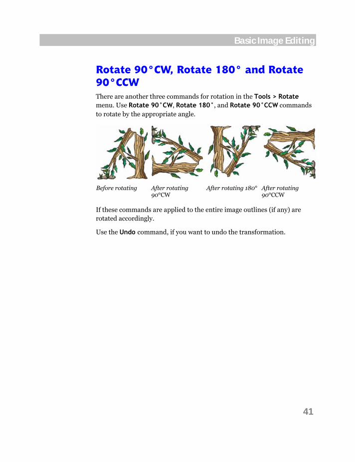
Rotate 90°CW, Rotate 180° and Rotate 90°CCW There are another three commands for rotation in the Tools > Rotate menu. Use Rotate 90°CW, Rotate 180°, and Rotate 90°CCW commands to rotate by the appropriate angle.
Before rotating After rotating 90°CW
After rotating 180° After rotating 90°CCW
If these commands are applied to the entire image outlines (if any) are rotated accordingly.
Use the Undo command, if you want to undo the transformation.

42
ScanFont 5
Removing Background Sometimes it may be useful to clean up the color background of an image with glyph shapes. For example, you could scan a very old manuscript with a yellow or even brown background:
In order to get a font from this image, all the glyph shapes have to be separated from their background. To make this process easier, try using the Remove Background command from the Tools > Filter menu:
Use the Mode dropdown list to select the base algorithm of the operation. You can remove background By luminosity or By color. You can try them all looking at the preview at the left to choose the best one. The more contrast in the preview the better splitting result you will get.

43
Basic Image Editing
Use the threshold control for better results:
You can undo this operation using the Edit > Undo command.
As a result you will get something like this:
Obviously this image is more useful for splitting into separate glyphs than the original one. But you can continue to enhance the image by using other commands from the Tools menu.

44
ScanFont 5
Brightness/Contrast The next two operations are useful for retouching color images. As seen from the command name you can change the brightness and the contrast of images with this command. In addition this operation helps control image transparency.
To edit the image brightness or contrast, select the Brightness/Contrast choice in the Tools > Adjust menu. You will see the dialog:
Move the Brightness slider to the left to make the image darker or to the right to make it lighter. Move the Contrast slider to the left to make the image lower contrast or to the right to make it higher contrast. Use the Transparency slider to make the image more or less transparent.
You can view the preview of the image in the preview field of the dialog. To see the original image, press and hold down the CTRL key.
Click on the OK button to apply the changes when finished, or Cancel to abort the operation.
Note: This operation does not work with black & white images.
Splitting an Image
After you edit an image and before you create a font you must split the image into separate shapes. When characters appear on paper (or in a computer-stored bitmap image) they are not “characters” anymore. They are nothing more than a collection of black (or color) spots of various shapes. To restore fonts from an image ScanFont must separate the image of each character from the images of other characters and put this character in the proper position in the collection of glyphs that is called a font.
Because there are differences between the shapes of the same character in different fonts, ScanFont cannot automatically recognize characters, like Optical Character Recognition (OCR) programs do. OCR programs are oriented to recognize a limited number of fonts and use advanced lexical-based algorithms to minimize recognition errors by trying to understand words, not just separate characters. In ScanFont we usually do not have words, just a collection of characters in any order. It is impossible for us to create a recognition algorithm that will understand characters in ScanFont. But we have created tools that simplify manual splitting of glyph shapes and have included a special feature that can automatically locate glyph shapes if they are printed in a known sequence. Our automatic separation feature usually produces very good results requiring few or no manual corrections.

46
ScanFont 5
Autosplitting Algorithms
To autosplit an image into glyph shapes:
1. Choose the Separate Shapes command in the Image menu or click on the Separate Shapes button on the Workflow toolbar:
The Separate Shapes dialog appears:
2. If you are working with a color image, use the Threshold by dropdown list and slider to define the boundaries between the white (or whatever color) paper and image pixels. This option works similarly to the Threshold operation discussed later. You will see the preview of the image changes in the left part of the dialog. Actually the threshold does not change your image or its colors; it is only needed to separate the future glyphs’ shapes from their background.

47
Splitting an Image
If you are working with a black & white image, you will see the "short" version of the dialog without the Separation mask section and preview.
3. Select the algorithm in the Separation Algorithm dropdown list. ScanFont has four autosplitting algorithms to use on different types of images. Here are descriptions with examples to illustrate the differences:
Table with borders
The image has an explicit table structure with cells of equal size separated by vertical and horizontal lines. These lines are treated as the boundaries between the glyphs but will not be added to the glyphs’ shapes
Table without borders
The image is the same as above but without vertical and horizontal lines. All the cells are of equal size
Book simple
The cells with separated glyphs are of the same height but have different advance widths. The cells produced by this algorithm cannot overlap each other, so overlapping shapes will occupy one cell which will need to be cut manually later
Book smart
An advanced heuristic algorithm producing cells that can overlap and have different heights and advance widths. It is based on the principle of the “magic wand” (areas selection)

48
ScanFont 5
4. Check the Skip spots that are less than option and enter the value if needed. This option, when checked, does not treat spots that are below the limit that you enter as glyph shapes or their parts. Such spots are ignored by the algorithm, helping you to avoid speckles of noise that cannot be removed by other operations.
5. Check the Automatically detect global baselines option if needed. The autosplit algorithm will locate all the strings and determine the baseline’s position in each string automatically. If outlines are present, the baseline’s position is calculated according to the outlines.
6. Click on the OK button to let ScanFont autosplit the image into cells using the selected algorithm.
If you are not satisfied with the autosplitting results, repeat the steps with another algorithm.

49
Splitting an Image
Customizing Autosplit
The Book smart algorithm is customizable. You can change its parameters by clicking on the More Options button in the Separate Shapes dialog. The Separate Shapes Options dialog will open:
The Automatically merge overlapping cells option allows you to combine cells that form glyphs like '%' when checked. The value in the editable field defines how much the cells must overlap to be combined into a single cell.
The Automatically merge stacked cells option allows you to combine cells that sit on top of other cells when checked. The value in the editable field defines the length of the most common projection in relation to the projection of a smaller cell.

50
ScanFont 5
Here is how our sample image looks after autosplitting it with all the default options:

51
Splitting an Image
Editing Splitting Data
There are no perfect automatic algorithms. Possible errors of the autosplit algorithm are:
1. If two glyphs touch or overlap each other too much they will be interpreted as a single glyph. These cells must be split manually:
2. Some multi-part glyphs will be interpreted as being separate glyphs. The split cells must be merged.
3. The positions of some of the baselines may be inaccurate. New baselines must be added or unnecessary baselines removed.
The tools for working with the split image are placed at the end of the Tools toolbar and have the following keyboard shortcuts:
C K U
52
ScanFont 5
Cell Tool
The Cell tool is the main tool for working with the split image. It is used to select and deselect cells for further operations on them. Every cell in the split image will become a glyph in the font that is generated from that image.
To select a cell, click on the Cell tool in the Tools toolbar and then click within the blue rectangle of the cell in the image. Select more cells by shift-clicking or dragging the mouse cursor while you hold down the mouse button. Use the Select All command in the Edit menu to select all the cells.
To deselect the selected cells one by one, click on the mouse cursor within the red rectangle of the selected cell while holding down the OPTION
key. To deselect all the cells, click anywhere outside the cells or use the Deselect command in the Edit menu.
To join two or more selected cells into one cell, select the Merge Cells command in the Image menu. The selected cells will be merged into one cell, which will remain selected.
To remove unwanted cells (that are not glyphs’ shapes, for example), select these cells with the Cell tool and then select the Delete command in the Edit menu or simply press the DEL key.
The Cell tool is also used to manually create cells in the image. You can use it to modify the results of automatic splitting or to do manual splitting from the outset.
To draw a new cell:
1. Select the Cell tool in the Tools toolbar and press CMD.
2. Position the mouse cursor at the corner of a rectangle to be defined as a cell.
3. Hold down the mouse button and drag the mouse to draw a rectangle around the glyph in the image.
4. Release the mouse button to finish defining a new cell. A new cell rectangle will appear.
53
Splitting an Image
You can define all the glyphs’ cells that you need in a font with this manual image splitting tool.
You can define cells with the Selection tools as well. Select part of an image with one of the image selection tools and then choose the Create Cell From Selection command in the Image menu. You will see the selection rectangle become a new cell.
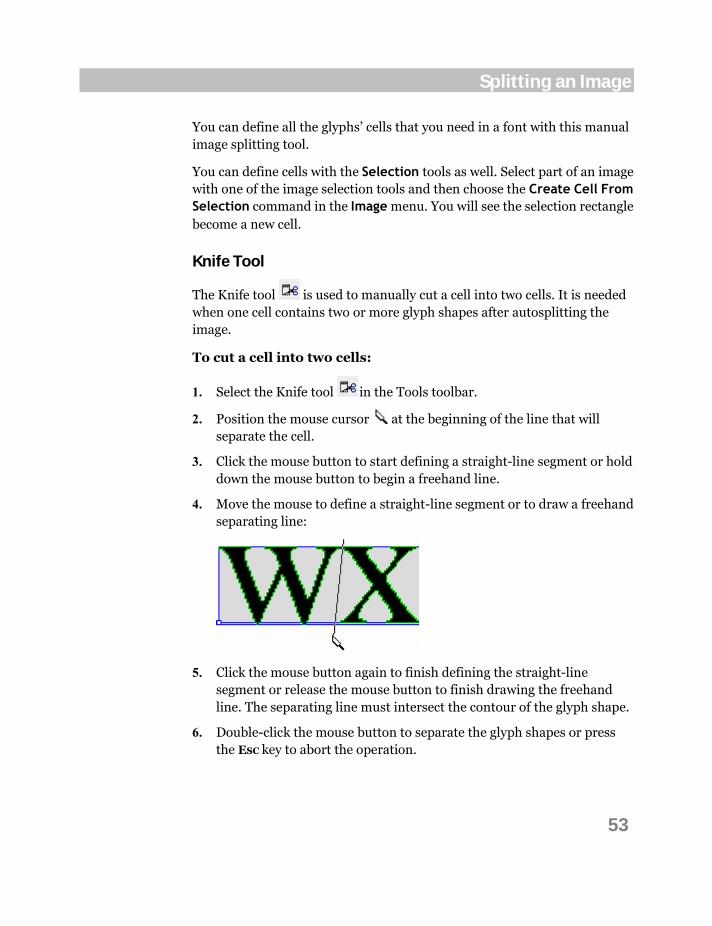
Knife Tool
The Knife tool is used to manually cut a cell into two cells. It is needed when one cell contains two or more glyph shapes after autosplitting the image.
To cut a cell into two cells:
1. Select the Knife tool in the Tools toolbar.
2. Position the mouse cursor at the beginning of the line that will separate the cell.
3. Click the mouse button to start defining a straight-line segment or hold down the mouse button to begin a freehand line.
4. Move the mouse to define a straight-line segment or to draw a freehand separating line:
5. Click the mouse button again to finish defining the straight-line segment or release the mouse button to finish drawing the freehand line. The separating line must intersect the contour of the glyph shape.
6. Double-click the mouse button to separate the glyph shapes or press the ESC key to abort the operation.
54
ScanFont 5
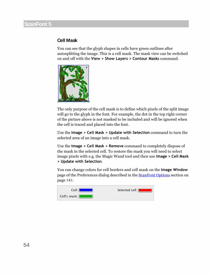
Cell Mask
You can see that the glyph shapes in cells have green outlines after autosplitting the image. This is a cell mask. The mask view can be switched on and off with the View > Show Layers > Contour Masks command.
The only purpose of the cell mask is to define which pixels of the split image will go to the glyph in the font. For example, the dot in the top right corner of the picture above is not masked to be included and will be ignored when the cell is traced and placed into the font.
Use the Image > Cell Mask > Update with Selection command to turn the selected area of an image into a cell mask.
Use the Image > Cell Mask > Remove command to completely dispose of the mask in the selected cell. To restore the mask you will need to select image pixels with e.g. the Magic Wand tool and then use Image > Cell Mask > Update with Selection.
You can change colors for cell borders and cell mask on the Image Window page of the Preferences dialog described in the ScanFont Options section on page 141:
55
Splitting an Image
Saving and Restoring Splitting Data
To save your image with all its separation information use the Save command from the File menu.
But you may want to save the image splitting data separately.
To save the splitting data:
1. Select the Save Separation Info command in the Image menu.
2. In the standard File Save dialog box that appears, select the folder where you want to save the data and enter the file name.
3. Click on Save to save the data.
Later you can load this saved data and apply it to the currently open image.
To load and apply the splitting data:
1. Select the Load Separation Info command in the Image menu.
2. In the standard File Open dialog box that appears, select the file with data.
3. Click on Open to load and apply the data to the image.
56
ScanFont 5
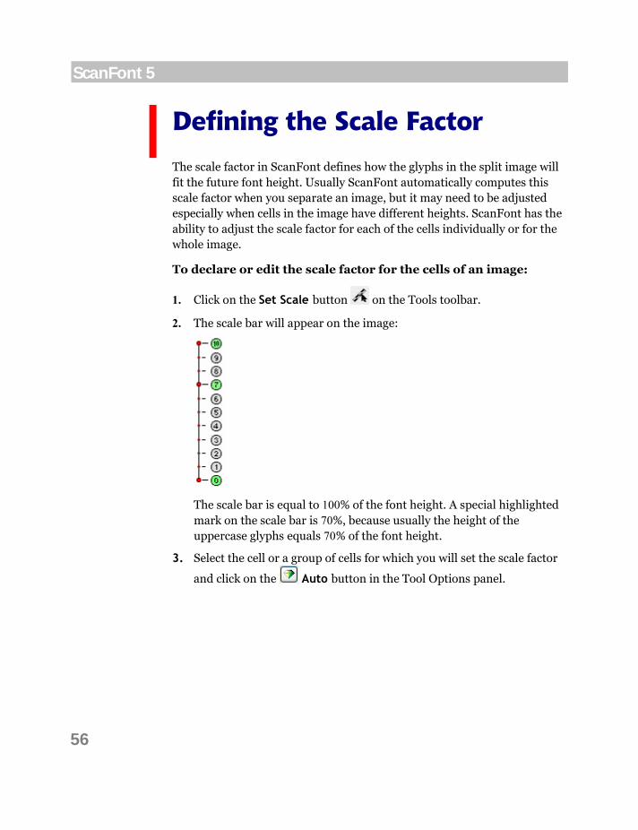
Defining the Scale Factor
The scale factor in ScanFont defines how the glyphs in the split image will fit the future font height. Usually ScanFont automatically computes this scale factor when you separate an image, but it may need to be adjusted especially when cells in the image have different heights. ScanFont has the ability to adjust the scale factor for each of the cells individually or for the whole image.
To declare or edit the scale factor for the cells of an image:
1. Click on the Set Scale button on the Tools toolbar.
2. The scale bar will appear on the image:
The scale bar is equal to 100% of the font height. A special highlighted mark on the scale bar is 70%, because usually the height of the uppercase glyphs equals 70% of the font height.
3. Select the cell or a group of cells for which you will set the scale factor
and click on the Auto button in the Tool Options panel.

57
Splitting an Image
If the cell has a baseline, the scale bar’s zero point is aligned to the cell’s baseline position:
If you are not satisfied with the results of the scale factor’s automatic detection, it can be adjusted manually. To do this, position the scale bar so that its length equals the font height.
To move the scale bar, position the mouse cursor on it (not too close to
an end). The mouse cursor will change to: . Hold down the mouse button and drag the scale bar to its new place. Release the mouse button to finish.
To position the ends of the scale bar, position the mouse cursor on
the end that you want to move. The mouse cursor will change to . Hold down the mouse button and drag the scale bar’s end. Release the mouse button to finish.
To keep the scale bar vertically or horizontally, hold down the SHIFT key on the keyboard. If you want to permanently prevent the scale bar from being slanted, enable this setting in the Preferences dialog:
Note that only the length of the scale bar makes sense.

58
ScanFont 5
You can see and edit the current scale value (actually the length of the scale bar) in the Tool Options panel. It is measured in image pixels:
The Auto button in the Tool Options panel sets the default scale factor for selected cells.
Note: If you want to reset all the scale changes you have made for individual
cells, deselect all cells and click on the Auto button in the Tool Options panel.

59
Splitting an Image
Editing Baselines
Usually, glyphs are aligned in strings in the source image. ScanFont uses this data to restore information about a glyph’s vertical positioning. In the string, glyphs are aligned to a baseline — the zero level of the string. Some glyphs lie above the baseline, some of them intersect the baseline, and some are below:
The definition of a baseline is the zero point of the vertical coordinates.
In ScanFont you can set baselines for every line of text or even for every glyph cell. When the glyphs are extracted from the image and placed into a font, the information about the relative position of the glyph’s image and baseline will be used, so you will not have to reposition the baseline in every glyph. Using baselines in the Image Window can save you a lot of time, as many glyphs are already aligned there. That is why we recommend that you align glyphs in strings when you prepare an original image.
ScanFont automatically detects the positions of all baselines when using the Separate Shapes operation. It analyses glyphs’ cells and tries to find the best position for the baselines.
If you want to change the positions of the baselines first make them visible.
To make baselines visible in the Image Window, select the Baseline item in the View > Show Layers menu.

60
ScanFont 5
To move a baseline:
1. Select the Cell tool in the Tools toolbar.
2. Position the mouse cursor on the baseline (the cursor changes to ).
3. Hold down the mouse button and drag the baseline where you want it to go. Release the mouse button to place the baseline in the new position:
To let ScanFont automatically detect the positions of all baselines again without performing autosplitting:
1. Select the Cell tool.
2. Make sure none of the cells selected.
3. Select the Search Again command in the Image > Baseline menu.
To set the position of a baseline for a string of cells:
1. Select the Cell tool.
2. Select the string of cells by SHIFT-clicking on or rectangular selection.
3. Select the Search Again command in the Image > Baseline menu.

61
Splitting an Image
There are some additional commands in the Image > Baselines menu. Here is their meaning:
Set To Cell’s Bottom This command sets the selected cell’s baseline (or all baselines if no cell is selected) to the cell’s bottom border. This is the same as clearing the cell’s baseline
Align To Top This command sets all the baselines of the selected cells to the position of the highest baseline
Align To Middle This command sets all the baselines of the selected cells to the position of the calculated average value
Align To Bottom This command sets all the baselines of the selected cells to the position of the lowest baseline
Auto Align This command sets all the baselines of the selected cells to the automatically calculated position.

62
ScanFont 5
Other Cell Commands
To create a new cell based on the selected area of your image:
1. Using one of the Selection tools, select the image portion.
2. Choose the Make Cell from Selection command in the Image menu.
To select the glyph’s shape of a cell:
1. Using the Cell tool, select the cell.
2. Choose the Make Selection from Cell command in the Image menu.
To set the cell size to the size of the glyph’s shape:
1. Using the Cell tool, select the cell.
2. Select the Detect Bounding Boxes command from the Image menu.


Creating Characters
When we know almost everything about the characters in an image, it is then time to put them into a font. This means that ScanFont must convert the bitmap images of the characters into the outline representations used in digital scalable fonts; assign the characters to their proper place in the font; and transfer all that information to an outline font editor.

65
Creating Characters
Outline Font Editor
As you know, ScanFont has no outline font-editing features, so you need another program to accept outline glyphs from ScanFont. We call programs that can accept data from ScanFont or other sources “Outline font-editing Applications”. FontLab Studio, AsiaFont Studio, and TypeTool are programs that can establish communication with ScanFont; accept data in outline and bitmap form; and report to ScanFont the results of the data transfer so it can react properly.
Please note that you must have one of the listed applications installed together with ScanFont in order to create outline fonts. You can customize the communication options on the Outline font editor page of the Preferences dialog:
See the detailed description of these options in the ScanFont Options section on page 141.
If you do not have any of the listed applications installed you still can choose to export outlines into VFB file — check the Export outline font into VFB file option.
66
ScanFont 5
Placing Characters into a Font
The last operation in creating a font from an image is to place the split glyphs into the font.
To place glyphs into a font:
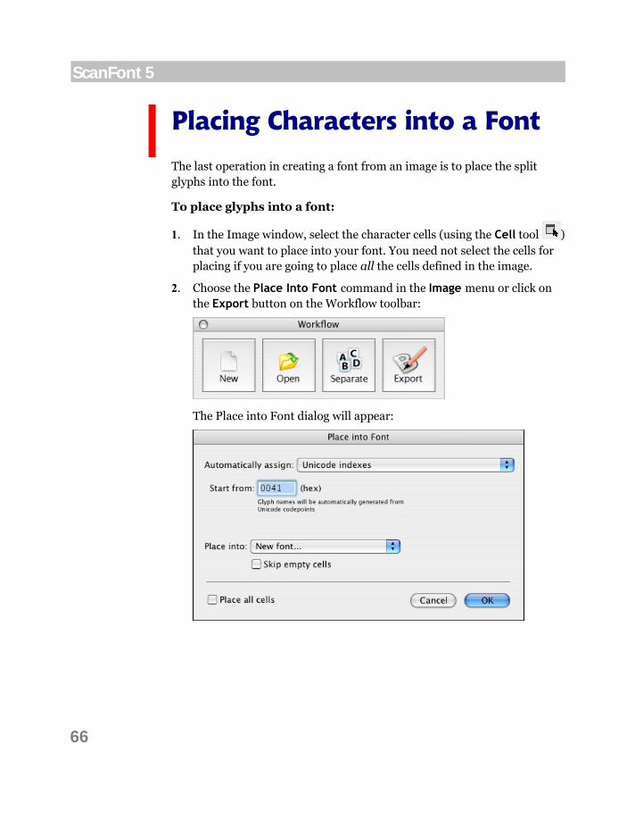
1. In the Image window, select the character cells (using the Cell tool ) that you want to place into your font. You need not select the cells for placing if you are going to place all the cells defined in the image.
2. Choose the Place Into Font command in the Image menu or click on the Export button on the Workflow toolbar:
The Place into Font dialog will appear:

67
Creating Characters
3. By choosing the Unicode indexes option in the Automatically assign dropdown list you make the program assign Unicode codepoints to new glyphs. It is also useful to enter the start value in the Start from field. Note that you must enter the start value in hexadecimal format. ScanFont will automatically assign names to glyphs by the assigned Unicode codepoints.
4. By choosing the Name template option in the Automatically assign dropdown list you can control the naming of exported glyphs. Sometimes it may be useful to enter the prefix and suffix values in the corresponding fields. Note that you can see the sample name at the right:
5. By choosing the Names option you can assign names using the ranges from the dropdown list:
Choose Nothing in the Automatically assign dropdown list if you do not want ScanFont automatically assign names and/or Unicode codepoints to glyphs.
6. Check the Place all cells option to place all the defined cells of the image. If no cells were selected this option is not available and all the defined cells will be placed into the font.
7. When you are finished defining cell placement click on the OK button. The Tracing Options dialog will appear on the screen. Set the parameters of bitmap tracing (described later) and click on the OK button again to finish the export process.
Note: Define the order of placement of the image cells and some other options in the Preferences dialog described in the ScanFont Options section on page 141.

68
ScanFont 5
If the Export outline font into VFB file option is off ScanFont will launch outline font editor and present another dialog:
Select the font opened in FontLab Studio (or TypeTool, or AFS) in the Place into dropdown list or choose New font and click on Export to finish.
If Export outline font into VFB file was switched on in The Preferences dialog ScanFont will open the standard File Save dialog box. Select the folder where you want to save the VFB file and enter the file name.
The bitmap glyphs will be converted to black & white mode (if not already), autotraced and transferred to the outline font-editing application (which will be launched if not already open) or exported in the vfb format. If the Export existing outlines only option was checked and there were cells with outlines in the image, these outlines will be transferred to the outline font-editing application (or exported to vfb) directly and the trace options will be ignored. The exported font will open in a new FontLab Studio (or TypeTool, or AFS) Font window, where you can start working with the outlines.
69
Creating Characters
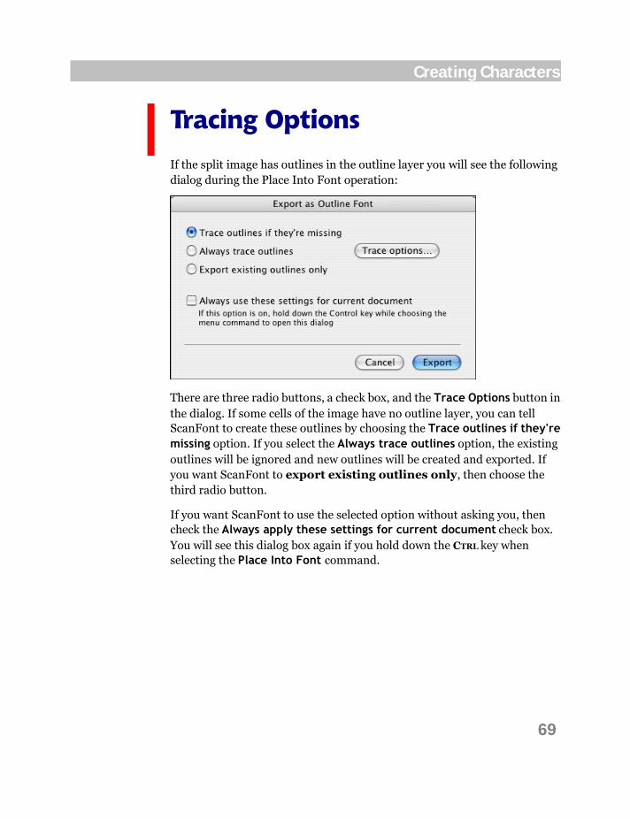
Tracing Options
If the split image has outlines in the outline layer you will see the following dialog during the Place Into Font operation:
There are three radio buttons, a check box, and the Trace Options button in the dialog. If some cells of the image have no outline layer, you can tell ScanFont to create these outlines by choosing the Trace outlines if they're missing option. If you select the Always trace outlines option, the existing outlines will be ignored and new outlines will be created and exported. If you want ScanFont to export existing outlines only, then choose the third radio button.
If you want ScanFont to use the selected option without asking you, then check the Always apply these settings for current document check box. You will see this dialog box again if you hold down the CTRL key when selecting the Place Into Font command.
70
ScanFont 5
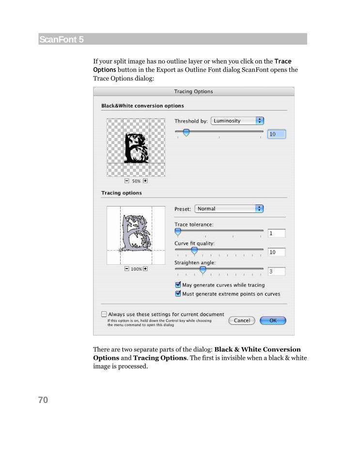
If your split image has no outline layer or when you click on the Trace Options button in the Export as Outline Font dialog ScanFont opens the Trace Options dialog:
There are two separate parts of the dialog: Black & White Conversion Options and Tracing Options. The first is invisible when a black & white image is processed.
71
Creating Characters
If a grayscale or color image is to be traced, you must define the parameters of conversion of the image to black & white in the upper part of the dialog. Choose the Threshold by conversion method in the dropdown list. Use the slider to adjust the threshold level if needed. (See the Threshold operation discussed later.) If a black & white image is autotraced, this option is not shown.
After you define the conversion method you can define the following tracing options:
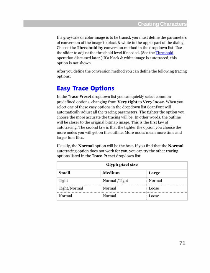
Easy Trace Options In the Trace Preset dropdown list you can quickly select common predefined options, changing from Very tight to Very loose. When you select one of these easy options in the dropdown list ScanFont will automatically adjust all the tracing parameters. The tighter the option you choose the more accurate the tracing will be. In other words, the outline will be closer to the original bitmap image. This is the first law of autotracing. The second law is that the tighter the option you choose the more nodes you will get on the outline. More nodes mean more time and larger font files.
Usually, the Normal option will be the best. If you find that the Normal autotracing option does not work for you, you can try the other tracing options listed in the Trace Preset dropdown list:
Glyph pixel size
Small Medium Large
Tight Normal /Tight Normal
Tight/Normal Normal Loose
Normal Normal Loose

72
ScanFont 5
Advanced Trace Options You can customize the autotracer parameters with the more detailed options below the Trace Preset dropdown list:
Trace tolerance Allows you to change the distance between the generated outline and the edge of the original bitmap
Curve fit quality Allows you to change the accuracy of curve fitting in the generated outline
Straighten angle Defines the angle between two lines within which the autotracer will replace several lines with one line
Tracer may generate curves
This option (active by default) allows the autotracer to generate curves
Tracer should generate extreme points on curves
This option (active by default) forces the autotracer to insert nodes at the extreme points of curves
Every time you change a parameter the preview to the left also changes allowing you to check your results. Use the zoom buttons of the preview if needed.
Clicking on the Cancel button will close the dialog without saving changes and stop the process of placing characters into a font. The outline font-editing application will not start in this case.
Note: The options that you define in the Trace Options dialog are used also when you select the Trace Bitmap operation described later in the Outline Operations section on page 129.

Advanced Image Editing
When you create glyphs by image importing, you may want to edit them to get the best result. Also you may want to draw all font glyphs from scratch.
ScanFont includes professional bitmap-editing tools and operations for this purpose. It is time to review them.
All editing tools and operations discussed here are equally applicable to scanned, imported or newly created images.
74
ScanFont 5
The Image Window
The Image Window is the main tool in ScanFont. It is a universal and very powerful image-editing module that also allows you to perform some font-specific operations.

75
Advanced Image Editing
Image Window Contents After you scan or import an image from a file or the Clipboard the image will be read and shown in the Image window:
The Image window helps you to preview, edit, and define those glyphs that will be placed into your font. It consists of the following parts and controls:
Editing Field Color Palette Current color box Scroll Bars Rulers Size dropdown list Zoom-in and Zoom-out buttons
The Tools toolbar becomes active when the Image window is open:
76
ScanFont 5
The tools are divided into three groups:
selection and drawing tools tools for working with character cells the Eye Dropper and Zoom tools.
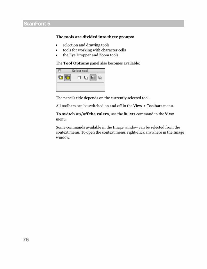
The Tool Options panel also becomes available:
The panel's title depends on the currently selected tool.
All toolbars can be switched on and off in the View > Toolbars menu.
To switch on/off the rulers, use the Rulers command in the View menu.
Some commands available in the Image window can be selected from the context menu. To open the context menu, right-click anywhere in the Image window.
77
Advanced Image Editing
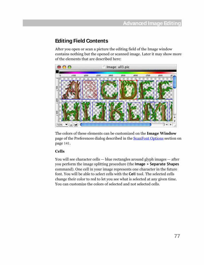
Editing Field Contents
After you open or scan a picture the editing field of the Image window contains nothing but the opened or scanned image. Later it may show more of the elements that are described here:
The colors of these elements can be customized on the Image Window page of the Preferences dialog described in the ScanFont Options section on page 141.
Cells
You will see character cells — blue rectangles around glyph images — after you perform the image splitting procedure (the Image > Separate Shapes command). One cell in your image represents one character in the future font. You will be able to select cells with the Cell tool. The selected cells change their color to red to let you see what is selected at any given time. You can customize the colors of selected and not selected cells.

78
ScanFont 5
Cell's mask
The cell's mask is visible as a green contour. The cell's mask outlines the part of the image that will be transferred to the tracing procedure during the Place Into Font operation. In the simplest case the cell's mask is the boundary between the black glyph image and the white background; but sometimes this may not include the whole glyph image. You can remove the cell's mask with the Image > Cell Mask > Remove menu command. The cell's rectangle will become the cell's mask in this case.
Note that the cell's mask is not the outline.
Baselines
ScanFont's autosplitting algorithm automatically determines the character's baselines. The baseline defines the vertical position of a character in a string. So every cell gets its own baseline represented by the blue horizontal line in the editing field. You may change the baseline's position by dragging it or with menu commands that we will describe later.
Outlines
Sometimes when both bitmap and outline information are available you can see dark red lines in the editing field. Characters' outlines cannot be edited in ScanFont but they can be exported or ignored later during the Place Into Font operation. Outlines can be removed with the Tools > Outline > Clear command.

79
Advanced Image Editing
Changing the View in the Image Window
To change the view in the editing field of the Image window, use the Scroll bars, Size dropdown list, Zoom buttons, and the View menu.
Scrolling
You can scroll the editing field using the Scroll Bars. The same action can be done by the Hand tool, which becomes available when you hold down the SPACEBAR key.
The top and left rulers can be switched on and off by using the Rulers command in the View menu.
Zooming
You can define magnification or reduction of the editing field of an image with the Size dropdown list. There are 26 zoom modes available in the list. The Zoom-in and Zoom-out buttons allow you to change the zoom mode of the editing field by one level at a time.
The zoom factor called Fit to window will automatically select the actual scale factor to fit the image in the window. This command is available in the Size dropdown list and in the View menu.
The maximum zoom-in is limited to 1600% magnification, and the minimum reduction is 10%. To magnify or reduce part of a glyph, select the Zoom tool (described later in this chapter).

80
ScanFont 5
View Menu In ScanFont every image contains several editing layers. Some of them are used when the font is exported; others are ScanFont-only and are used to help you work with the image. Below is the list of all the layers that you can see in the Image window.
Bitmap Main layer containing the bitmap image
Grid Shows regular grid in the editing field in large zoom modes
Outline Shows image outline layer (it is usually empty)
Baseline Shows baselines
Image Cells Shows cell rectangles in a split image
Contour Masks Shows cell mask in a split image
You can control the layers’ appearance and features with the View > Show Layers menu. If you frequently need to switch some layers on and off you can open the Show Layers toolbar with the View > Toolbars > Layers command:
The View > Transparency menu contains the following options:
As small grid Shows image transparency as small grid
As medium grid Shows image transparency as medium grid
As large grid Shows image transparency as large grid
As color Shows image transparency as color background
Select color Allows you to choose color for image transparency.
Choose Transparency > As grid if you want to see a transparent background in the Image window. Select the size of the grid from the Small grid, Medium grid, or Large grid choices in the View > Transparency menu. The size of the grid affects only the view of the editing field, not the image itself.

81
Advanced Image Editing
To view the image background as colored, select the Transparency > As color command in the View menu. The default color for transparency is white, but you can change it using the Select Color command (which brings up the standard Macintosh Select Color dialog) in the View > Transparency menu. Changing the view of transparency does not affect the real transparency of drawing colors. It defines only how the transparency is shown in the window.
You may choose to change other viewing options on the Image Window page of the Preferences dialog box described in the ScanFont Options section on page 141.
With the View menu, you can also show and hide toolbars, rulers and panels.

82
ScanFont 5
Info Panel When working with an image, the Info panel may become useful. To make it visible on the screen, select the Info Panel command in the View menu:
The upper part of this panel contains color information for the pixel under the mouse cursor: its RGB values and the opacity value (0-255). If you are editing an image that has no transparency layer (less than with millions of colors), the opacity value is replaced with the gray level in percents. When a black & white image is edited, RGB values are not shown:
The bottom part of the Info panel contains the horizontal (x) and vertical (y) coordinates of the pixel under the mouse cursor. The origin point has zero values and pixels are counted from the top left corner of the image. The next pair of values show the width (w) and the height (h) of a selection, if any.

83
Advanced Image Editing
There is another way to open the Info panel: position the mouse cursor over the Current Color box in the Image window and hold down the mouse button:
The information panel for the current color appears. Drag the mouse outside this panel and release the mouse button. The Info panel will appear on the screen where the mouse button was released.

84
ScanFont 5
Context Menu Some commands available in the Image window can be selected from the context menu. To open the context menu, right-click anywhere in the editing field. Here is a sample of the Image window context menu:
Here is what the commands mean:
Remove Background
Opens the Remove Background dialog allowing you to clean up color image background
Change Color Opens the Change Color Mode dialog for the current image
Separate Shapes Starts autosplitting for the current image
Merge Cells Merges two or more selected cells
Search Baselines Automatically detects the positions of all baselines in the split image
Place Into Font Opens the Place Into Font dialog.
85
Advanced Image Editing
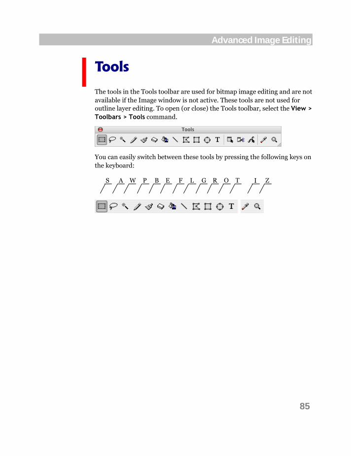
Tools
The tools in the Tools toolbar are used for bitmap image editing and are not available if the Image window is not active. These tools are not used for outline layer editing. To open (or close) the Tools toolbar, select the View > Toolbars > Tools command.
You can easily switch between these tools by pressing the following keys on the keyboard:
S A W P E F L B G R O T I Z
86
ScanFont 5
Selecting You can select the entire editing field of the window by the Select All command in the Edit menu. If you want to deselect any previously selected area, use the Deselect command in the Edit menu. To deselect the selected area and select the unselected area simultaneously, use the Select Inverse command.
Additionally there are three selecting tools in the Tools toolbar: Select tool, Select Region tool and Magic Wand.
Any selected part of the bitmap can be moved around the editing field by dragging it. It can be cut, copied, pasted, and cleared by the corresponding choices in the Edit menu or buttons in the Standard toolbar.
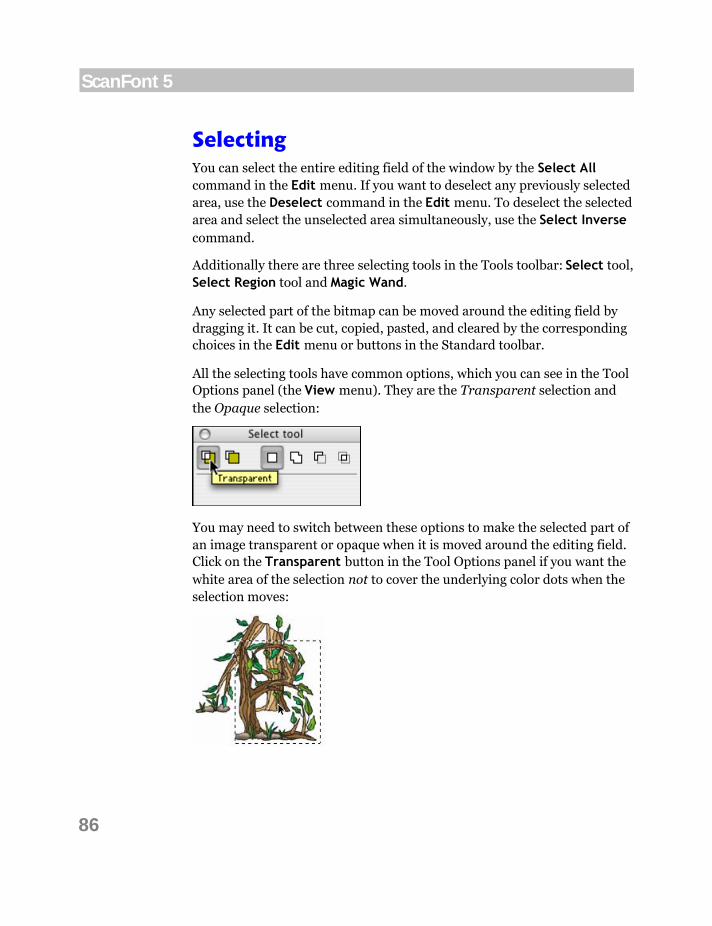
All the selecting tools have common options, which you can see in the Tool Options panel (the View menu). They are the Transparent selection and the Opaque selection:
You may need to switch between these options to make the selected part of an image transparent or opaque when it is moved around the editing field. Click on the Transparent button in the Tool Options panel if you want the white area of the selection not to cover the underlying color dots when the selection moves:

87
Advanced Image Editing
Click on the Opaque button if you want the white area of the selection to overlap color areas of the underlying image:
You can change these options at any time, not just before making a selection.
The following selecting mode buttons
allow you to modify the selected area, i.e. to add or to subtract from the selection.
Any selection action can be undone by the Undo command of the Edit menu.

88
ScanFont 5
Select Tool
Use the Select tool to outline a rectangular area and display it with a grid.
To select a rectangular part:
1. Choose the Select tool in the Tools toolbar.
2. Put the mouse cursor on one of the corners of the rectangle that you want to select.
3. Hold down the mouse button and move the mouse cursor to the opposite corner of the area that you want to select.
4. Release the mouse button.
Tip: To temporarily switch to the Select tool while another tool is active, hold down the CMD key on the keyboard.
To add to the selection, hold down the SHIFT key or use the Add to selection button in the Tool Options panel. The cursor will change to . The new selection will be added to the previously selected area.
To subtract from the selection, hold down the OPTION key or use the Subtract from selection button in the Tool Options panel. The cursor will
change to . The new selection will be subtracted from the previously selected area.
To subtract from the selection, hold down OPTION+SHIFT or use the Intersect with selection button in the Tool Options panel. The cursor will change to . Only the common area of the new and previous selection will be selected.
To deselect the area, click outside of the selected area, or CMD-click inside the area, or use the Deselect command in the Edit menu.

89
Advanced Image Editing
Select Region Tool
With the Select Region tool, you can select areas of any shape. The area may be selected on a point-by-point basis or by drawing a free-hand line.
To select a free-form part of an image:
1. Choose the Select Region tool in the Tools toolbar.
2. Position the mouse cursor on one of the points on the edge of the selection area.
3. Hold down or click the mouse button. If you click the left down button, you will add a new straight line to the selection polygon. If you hold the mouse button and drag the mouse, you will draw a freehand line that will be added to the selection:
or
4. Double-click the mouse button to finish the selection.
To add to the selection, hold down the SHIFT key or use the Add to selection button in the Tool Options panel. The cursor will change to . The new selection will be added to the previously selected area.
To subtract from the selection, hold down the OPTION key or use the Subtract from selection button in the Tool Options panel. The cursor will
change to . The new selection will be subtracted from the previously selected area.
To subtract from the selection, hold down OPTION+SHIFT or use the Intersect with selection button in the Tool Options panel. The cursor will
change to . Only the common area of the new and previous selection will be selected.
To deselect the area, CMD-click inside the area or use the Deselect command in the Edit menu.

90
ScanFont 5
Magic Wand Tool
The easiest selection tool is the Magic Wand. It automatically detects the area to select by its color attributes and creates a freehand selection. It is very useful in selecting a glyph shape.
To select a non-white area of an image:
1. Select the Magic Wand tool in the Tools toolbar.
2. Move the mouse cursor over the glyph that you want to select.
3. Click the mouse button to select the glyph.
Hold down the SHIFT key to add a new selection to the current selection or hold down the OPTION (or OPTION+SHIFT) key to subtract from the selection.
To deselect the area, CMD-click inside the selected area or use the Deselect command in the Edit menu.
The Magic Wand tool has one additional option in the Tool Options panel:
It is called Tolerance. Its value can be changed in the range from 0 to 100. When tolerance is equal to 0, the Magic Wand will select pixels precisely of one color only. The greater the tolerance value is, the larger the area that will be selected by the Magic Wand. This option is, of course, not useful with black & white images. All values except 100 will lead to selection of only the black pixels in this case.

91
Advanced Image Editing
Operations on a Selection Selection is used to choose part of the image on which to apply transformations. In this section we will discuss methods of transforming selected areas.
Moving a Selection
To move a selected area:
1. Choose a selection tool (Select, Select Region or Magic Wand).
2. Move the mouse cursor inside the selection area.
3. Hold down the mouse button and drag the selection to the new place.
4. Release the mouse button to finish moving or press the ESC key on the keyboard to abort the operation.
To constrain movement to the horizontal or vertical direction, hold down the SHIFT key after pressing the mouse button, and drag the mouse.
You can move the selected area by one pixel using the ARROW keys.
92
ScanFont 5
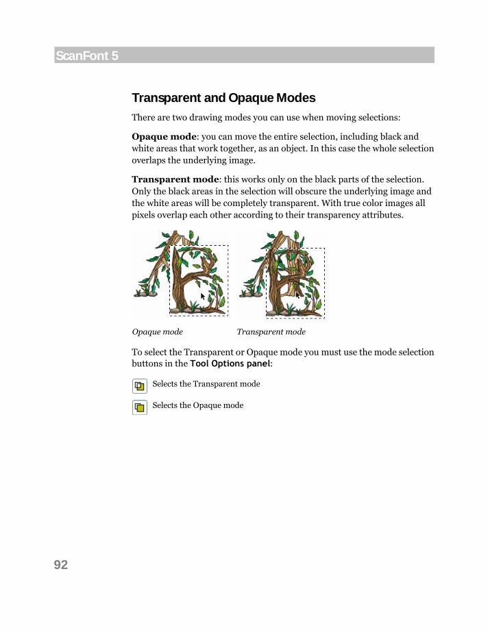
Transparent and Opaque Modes
There are two drawing modes you can use when moving selections:
Opaque mode: you can move the entire selection, including black and white areas that work together, as an object. In this case the whole selection overlaps the underlying image.
Transparent mode: this works only on the black parts of the selection. Only the black areas in the selection will obscure the underlying image and the white areas will be completely transparent. With true color images all pixels overlap each other according to their transparency attributes.
Opaque mode Transparent mode
To select the Transparent or Opaque mode you must use the mode selection buttons in the Tool Options panel:
Selects the Transparent mode
Selects the Opaque mode
93
Advanced Image Editing
Copying and Pasting a Selection
To copy a selection into another application or into another image, use the Copy and Paste commands from the Edit menu.
With the Copy command you can place a copy of the selection area onto the Clipboard, making it available to any application that can read bitmap images.
The Paste command reads bitmap images from the Clipboard and places them into the current editing field.
The Cut command combines Copy and Delete operations, so a copy of the selection is placed on the Clipboard, but the selection is deleted.
Deleting a Selection
To remove a selection from the image, select the Delete command in the Edit menu or press the DEL key on the keyboard. The selection will be removed and filled with white or transparency color.
Do not forget you can use the Undo command if you want to undo the deletion.
Transforming a Selection
You can use the commands from the Tools menu to transform a selected area of an image. If you have a selection within the image, transformation commands are applied to the selection. If there is no selection, the commands are applied to the entire image. All these operations will be discussed later in the Operations section on page 106.

94
ScanFont 5
Drawing You can draw a new glyph image or modify an existing one using the drawing tools. ScanFont’s bitmap editor includes the following drawing tools:
Pencil
Draws thin 1-pixel lines or sets or clears individual pixels. Very useful in the Zoom-In mode
Brush
Main drawing and painting tool. Draws strokes of selected width and shape
Eraser
Clears areas of an image
Fill
Fills closed areas with selected color
Line
Draws straight lines
Polygon
Draws filled or unfilled polygons
Rectangle
Draws filled or unfilled rectangles and squares
Ellipse
Draws filled or unfilled circles and ellipses
Text
Enters text
The default color for drawing is black. You can change the current color by selecting one in the Color Palette. All the tools except the Text tool may draw with any color.
While drawing you can change your drawing tool temporarily:
to the Select tool by holding down the CMD key, or to the Eye Dropper tool by holding down the OPTION key, or to the Hand tool by holding down the SPACEBAR key, or to the Zoom-In tool by holding down the CMD+SPACEBAR keys, or to the Zoom-Out tool by holding down the CMD+OPTION+ SPACEBAR
keys.
Note: If there is a selected area anywhere in the editing field, drawing will take place only within this selected area.
95
Advanced Image Editing
Selecting Colors
The image editor in ScanFont is actually a powerful color image-retouching module. As in any image editing application you can select drawing colors in color palettes. The ScanFont color palette resides at the top of the Image window.
There are three ways to set the current color in the Image window:
With the Color Palette With the Color dialog box and with the Eyedropper tool
To set the current color with the Color Palette, move the mouse cursor to the palette bar (the cursor will change to the Eye Dropper cursor) and click the mouse button over the color you need. The selected color will be shown in the Current Color box.
To set the current color with the Color dialog box, double-click on the palette bar or the Current Color box. The standard Macintosh Color dialog box will open. Select the color you need in this dialog and click on the OK button. The selected color will be shown in the Current Color box. This method is better if you want to set a precise color by entering its numeric RGB values.
To set the current color with the Eyedropper tool, select this tool in the Tools toolbar or press the OPTION key on the keyboard; position the mouse cursor over the image; and click the mouse button. The color of the pixel you clicked on will be shown in the Current Color box.

96
ScanFont 5
To see the numeric values of the currently selected color, position the mouse cursor over the Current Color box. You will see the panel popups with RGB and opacity color information:
Hold down the mouse button, drag the mouse and release the mouse button to open the Info panel instantly:
Note that the Info panel shows the color information for the image pixel under the mouse cursor, not the current color.
You can hide/show the Info Panel at any time by the command in the View menu.

97
Advanced Image Editing
Color Palettes
Sometimes it is useful to have the color palette in a separate floating window. To open this window, select the Palette Panel command in the View menu. The Palette panel will appear with the default color palette:
Tip: You can drag this window out right from the Color Palette bar of the Image window.
Now you can use the Palette panel along with the Color Palette in the Image window. You can drag it around the screen to find the most convenient place. To resize the panel, click on and drag its right bottom corner.
There are two small controls at the bottom left corner of the Palette panel that are used to change the palettes in the window.
To change the color palette in the panel, use the Select Palette dropdown list:
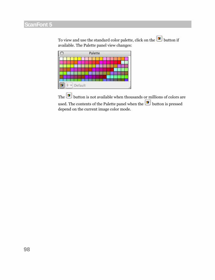
98
ScanFont 5
To view and use the standard color palette, click on the button if available. The Palette panel view changes:
The button is not available when thousands or millions of colors are
used. The contents of the Palette panel when the button is pressed depend on the current image color mode.
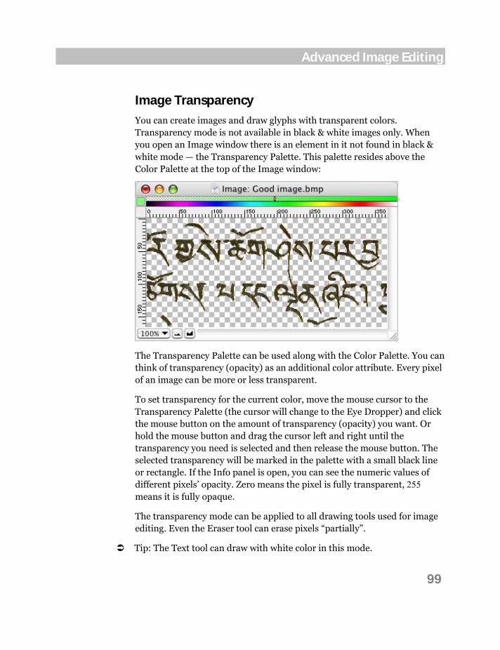
99
Advanced Image Editing
Image Transparency
You can create images and draw glyphs with transparent colors. Transparency mode is not available in black & white images only. When you open an Image window there is an element in it not found in black & white mode — the Transparency Palette. This palette resides above the Color Palette at the top of the Image window:
The Transparency Palette can be used along with the Color Palette. You can think of transparency (opacity) as an additional color attribute. Every pixel of an image can be more or less transparent.
To set transparency for the current color, move the mouse cursor to the Transparency Palette (the cursor will change to the Eye Dropper) and click the mouse button on the amount of transparency (opacity) you want. Or hold the mouse button and drag the cursor left and right until the transparency you need is selected and then release the mouse button. The selected transparency will be marked in the palette with a small black line or rectangle. If the Info panel is open, you can see the numeric values of different pixels’ opacity. Zero means the pixel is fully transparent, 255 means it is fully opaque.
The transparency mode can be applied to all drawing tools used for image editing. Even the Eraser tool can erase pixels “partially”.
Tip: The Text tool can draw with white color in this mode.

100
ScanFont 5
Pencil Tool
The Pencil is the simplest drawing tool in ScanFont. It draws a one-pixel-wide line and can be used to set or clear individual pixels. The Pencil tool can be used at any zoom but it is easier to use it at zoom levels of 5:1 or greater.
To set or clear an individual pixel on a glyph, move the mouse
cursor onto the pixel you want to edit and click on the mouse button. This sets a pixel to the current color. Another click on the same pixel clears the pixel.
To draw a thin line with the current color, press the mouse button and drag the mouse. You can draw a straight line by clicking on a beginning node and then clicking on sequential final nodes while holding down the SHIFT key.
Press the ESC key on the keyboard while drawing to abort drawing a line.
Brush Tool
The Brush is a wide version of pencil. See the description of the tool in the Brush Tool section on page 31.
Eraser Tool
The Eraser tool may be used to clear portions of the image.
As with the brush tool, you may set diameter, roundness, angle and hardness of the eraser in the Brushes panel. Tablet options affect the Eraser tool as well.
Of course, you can press the ESC key to abort the erasing process.
101
Advanced Image Editing
Fill Tool
The Fill tool is used to fill areas filled with one color. It works similarly to the Magic Wand tool.
To fill an area (filled with one color) with the current color using the Fill tool:
1. Select the Fill tool in the Tools toolbar and a color in the palette.
2. Move the mouse cursor to the area you wish to fill.
3. Click the mouse button to fill this area with the current color.
To fill a selection with the current color, use the Edit > Fill Selection command.
Line Tool
This tool draws straight lines with the brush that you select in the Brushes panel.
To draw a straight line:
1. Select the Line tool in the toolbar and a color in the palette.
2. Position the mouse cursor at the beginning of the line.
3. Hold down the mouse button and drag the mouse to define a line.
4. Hold down the SHIFT key to constrain the line direction to 45-degree increments.
5. Release the mouse button to finish drawing the line or press the ESC key to abort.

102
ScanFont 5
Polygon Tool
This tool can be used to draw closed polygons with the interior filled or empty.
As with all the other tools you can choose the current color in the Color Palette.
To draw a polygon:
1. Select the Polygon tool in the Tools toolbar.
2. Position the mouse cursor on the first point of the polygon.
3. To add a straight-line segment to a polygon, click the mouse button. Then move the mouse to define the line segment and click the mouse button again.
4. To add a freehand segment to a polygon, press down the mouse button (but do not release it) and drag the mouse to draw the freehand segment. Release the mouse button to accept it.
5. To finish drawing a polygon, double-click the mouse button at the last point to be added.
6. To abort drawing, press the ESC key.
The polygon will be filled with the current color if the Fill interior check box in the Tool Options panel was checked:
Rectangle and Ellipse Tools
See the description of these tools in the Rectangle and Ellipse Tools section on page 36.
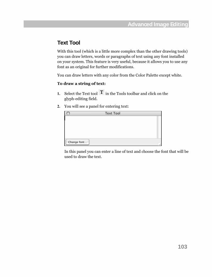
103
Advanced Image Editing
Text Tool
With this tool (which is a little more complex than the other drawing tools) you can draw letters, words or paragraphs of text using any font installed on your system. This feature is very useful, because it allows you to use any font as an original for further modifications.
You can draw letters with any color from the Color Palette except white.
To draw a string of text:
1. Select the Text tool in the Tools toolbar and click on the glyph-editing field.
2. You will see a panel for entering text:
In this panel you can enter a line of text and choose the font that will be used to draw the text.

104
ScanFont 5
3. Click on the Font button at the lower left corner to select the font. You will see the font-selection dialog box, in which you can select the typeface, style and point size of the text that you are drawing:
4. Make your selection and click on the OK button.
5. Type the letter or text that you want to draw in the glyph window. You will see the text objects containing the text immediately appear in the glyph window while you are typing:
6. You can work with the text object as with any selection. Use the Text tool like any other selection tool to move or copy a text object. Refer to the Selecting section on page 86 for information about selection tools.
7. Choose a transparent or opaque mode for the text object in the Tool Options panel.
8. Click the mouse button anywhere outside the selection to accept the position of the text object and begin entering a new one.

105
Advanced Image Editing
Other Tools
Eye Dropper Tool
The Eye Dropper is a tool for quick color selection from the colors already used in the drawing. You can choose the Eye Dropper by selecting the
tool in the Tools toolbar or by pressing and holding down the OPTION
key while another tool is active. To make any color in the editing field the
current color, drag the lower edge of the mouse cursor to that color and click the mouse button. The color under the cursor becomes the current color for drawing tools.
If the Info panel is visible, the digital RGB values of the current color appear in it.
You cannot undo this operation.
Zoom Tool
See the description of the Zoom tool in the Zoom Tool section on page 37.

106
ScanFont 5
Operations
You can transform an open image or a selected part of an image using the commands from the Tools menu. If there is no selection, transformation commands are applied to the whole image. If you select a part of an image, transformations are applied to the selection.
Note: Some commands are not available in the Tools menu if you are editing a black & white image.
Some commonly used transformation commands have corresponding buttons in the Operations toolbar for easy access:
The buttons in the Operations toolbar are:
Flip Horizontal
Flips the image or selection horizontally
Flip Vertical
Flips the image or selection vertically
Scale
Scales the image or selection
Rotate
Rotates the image or selection by the given angle
Rotate 180°
Rotates the image or selection 180 degrees
Rotate 90° CW
Rotates the image or selection 90 degrees clockwise
Rotate 90° CCW
Rotates the image or selection 90 degrees counter-clockwise
Slant
Slants the image or selection to imitate italics
Make Bold
Shifts the image or selection by several pixels to imitate bold style
Do not forget that you can use the Undo command if you want to undo any of the transformations.

107
Advanced Image Editing
Flip Horizontal and Flip Vertical When you want to flip an image in the vertical or horizontal direction, you use the Flip Horizontal or Flip Vertical commands from the Tools menu.
Before flipping After horizontal flipping After vertical flipping
As with other commands from the Tools menu this command may be applied to the selected areas of an image, but when there is no selection, it will apply to the entire image. In the latter case outlines (if any) are flipped accordingly. These operations may be necessary when you edit symmetrical glyphs.
Use the Undo command to undo the transformation.

108
ScanFont 5
Slant This is the special transformation command that can help you make an oblique image from a plain one.
To slant the image:
1. Select the Slant command in the Tools menu. You will see the Slant dialog:
2. Enter the angle for slanting (12 degrees by default) and click on the OK button. To abort the operation, click on Cancel.
Before After
You can see the preview of the image in the preview field of the dialog while changing the slant angle. To see the original, press and hold down the CTRL
key.
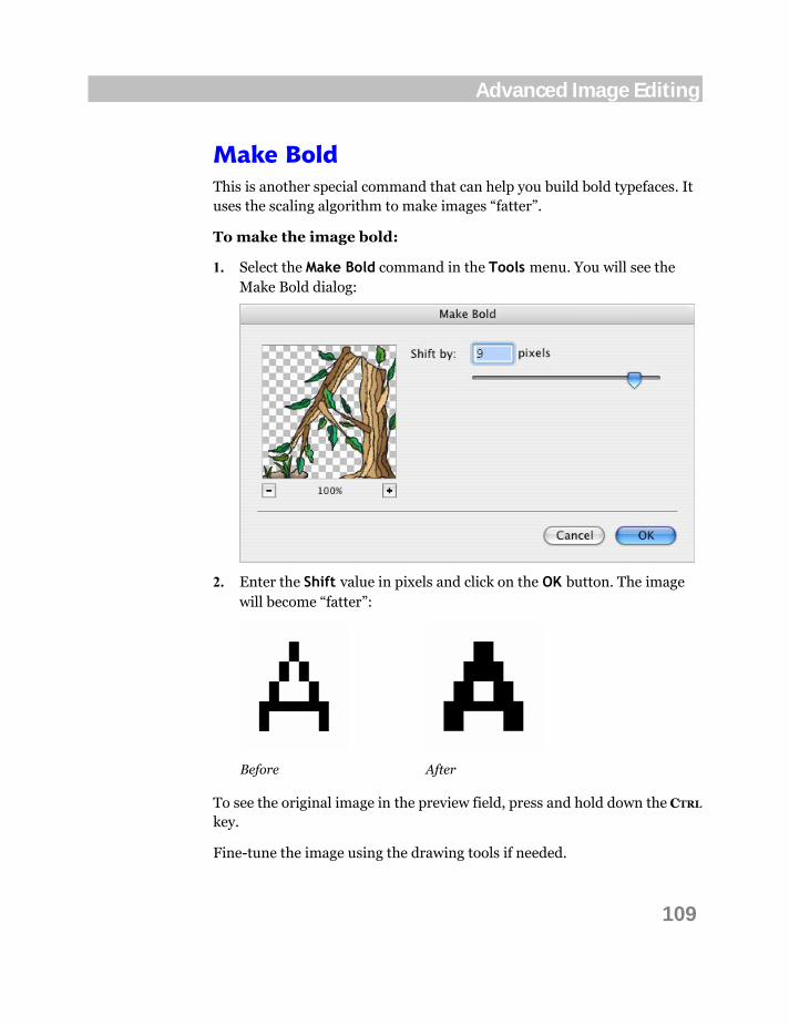
109
Advanced Image Editing
Make Bold This is another special command that can help you build bold typefaces. It uses the scaling algorithm to make images “fatter”.
To make the image bold:
1. Select the Make Bold command in the Tools menu. You will see the Make Bold dialog:
2. Enter the Shift value in pixels and click on the OK button. The image will become “fatter”:
Before After
To see the original image in the preview field, press and hold down the CTRL
key.
Fine-tune the image using the drawing tools if needed.

110
ScanFont 5
Shift The Shift operation is used to move the whole image or its selected part in vertical or horizontal direction relatively to image cells and their baselines.
When you select the Shift command in the Tools menu, the Shift dialog opens:
The only thing that you can do with this operation is to move the image horizontally or vertically. For example, you may want to move several glyphs up or down at a time. Positive values shift glyph(s) up and right, negative values shift down and left.
You can use the Undo command to undo the Shift operation.
Clear Bitmap The Tools > Clear Bitmap command erases the contents of the bitmap layer. Outlines in the outline layer are preserved if any. Use the Undo command, if you want to undo the operation.
Brightness/Contrast See the description of this operation in the Brightness/Contrast section on page 44.

111
Advanced Image Editing
Hue/Saturation This operation is also useful for retouching color images. As seen from the command name you can use it to change the hue and the saturation of an image colors.
To edit the image hue, saturation or lightness, select the Hue/Saturation item in the Tools > Adjust menu. You will see the Hue/Saturation dialog:
Use the Hue slider to change the color hue of the image. Move the Saturation slider to the left to make the colors less saturated or to the right to make them more saturated. Move the Lightness slider to the left to make the image darker or to the right to make it lighter.
You can preview the image in the preview field of the dialog. To see the original image, press and hold down the CTRL key. Click on the OK button to apply changes when finished, or Cancel to abort the operation.
Note: This operation does not work with black & white images.

112
ScanFont 5
Threshold The Threshold command fills light pixels of the image with white color and dark pixels with black. Actually it turns color images into black & white images, but it does not change the image color mode. The boundary between “light” and “dark” can be defined in the Threshold dialog:
The threshold operation can be performed by one of the following parameters:
Luminosity The luminance countered from pixel’s red, green and blue channels
Opacity Pixel’s opacity/transparency component (for fonts with millions of colors)
Color Pixel’s hue angle

113
Advanced Image Editing
To see the original image, press and hold down the CTRL key.
Before After
This command cannot be applied to an image more than once.
Note: This operation does not work with black & white images.

114
ScanFont 5
Invert The Invert command inverts image colors. In the simplest case the white pixels become black and the black pixels that compose the glyph shape become white:
Before After
Use the Undo command to undo the operation.

115
Advanced Image Editing
Colorize The Colorize command is the opposite of the Threshold command in a sense. It does not change the image color mode either, but it allows you to fill all black areas with one color or even with a color/grayscale pattern.
To colorize the image, select the Colorize command in the Tools > Filter menu and select the options in the Colorize dialog:
Select a method of determining what pixels should be colorized in the Assign by dropdown list.
Select a mode of image colorizing: Color or Picture.
If you choose Color, select the color that will be applied to the shapes of glyphs in the standard Colors dialog. Check the Add Noise option to add some noise to a solid color you have selected. You may choose to add different amount of noise and apply it to this or that component of RGB.

116
ScanFont 5
If you choose the Picture mode, click on the Browse button and choose the PNG or TIFF pattern file to be applied to the image:
You may choose any image that can be produced with your image-editing applications, even your latest digital photo.
Select the appropriate Alignment in the corresponding menu. The following variants of aligning the pattern to the image are available:
Random The image is filled with the pattern randomly
Whole The image is filled with the pattern scaled to the image size
Top Left The pattern fills the image aligned to the pattern’s top left corner
Top Centered The pattern fills the image aligned to the pattern’s top edge and centered horizontally
Top Right The pattern fills the image aligned to the pattern’s top right corner
Centered Left The pattern fills the image aligned to the pattern’s left edge and centered vertically
Centered The image is filled with the pattern centered vertically and horizontally in the image
Centered Right The pattern fills the image aligned to the pattern’s right edge and centered vertically
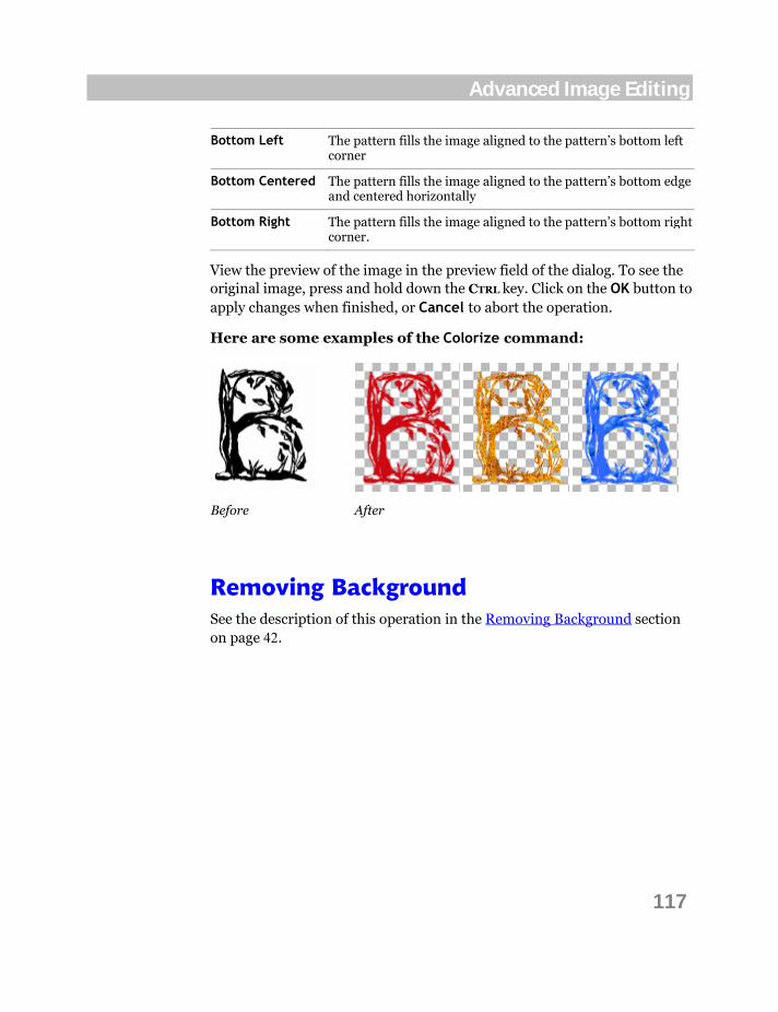
117
Advanced Image Editing
Bottom Left The pattern fills the image aligned to the pattern’s bottom left corner
Bottom Centered The pattern fills the image aligned to the pattern’s bottom edge and centered horizontally
Bottom Right The pattern fills the image aligned to the pattern’s bottom right corner.
View the preview of the image in the preview field of the dialog. To see the original image, press and hold down the CTRL key. Click on the OK button to apply changes when finished, or Cancel to abort the operation.
Here are some examples of the Colorize command:
Before After
Removing Background See the description of this operation in the Removing Background section on page 42.

118
ScanFont 5
Emboss This command and the remaining ones from the Tools > Filter menu may be qualified as filters. They are usually used for color image editing. Emboss is a special filter command that will make the image look high relief.
To make the image high relief (embossed):
1. Select the Emboss command in the Tools > Filter menu. You will see the Emboss dialog:
2. Use the Angle, Height and Amount sliders to customize the filter and click on the OK button. The Emboss filter will be applied.
To see the original image in the preview field, press and hold down the CTRL
key.
Before After
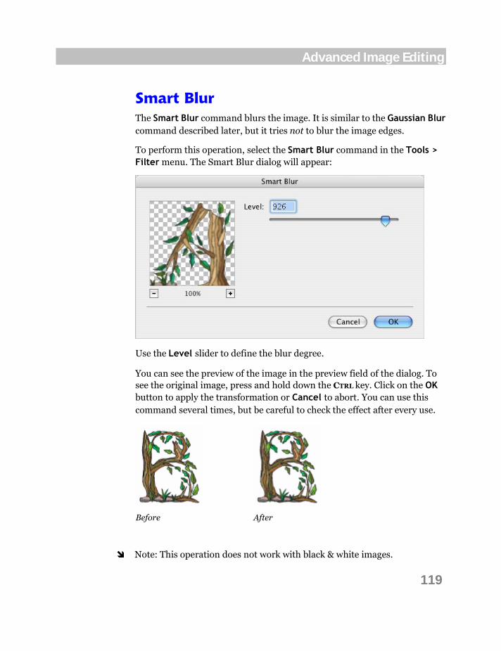
119
Advanced Image Editing
Smart Blur The Smart Blur command blurs the image. It is similar to the Gaussian Blur command described later, but it tries not to blur the image edges.
To perform this operation, select the Smart Blur command in the Tools > Filter menu. The Smart Blur dialog will appear:
Use the Level slider to define the blur degree.
You can see the preview of the image in the preview field of the dialog. To see the original image, press and hold down the CTRL key. Click on the OK button to apply the transformation or Cancel to abort. You can use this command several times, but be careful to check the effect after every use.
Before After
Note: This operation does not work with black & white images.
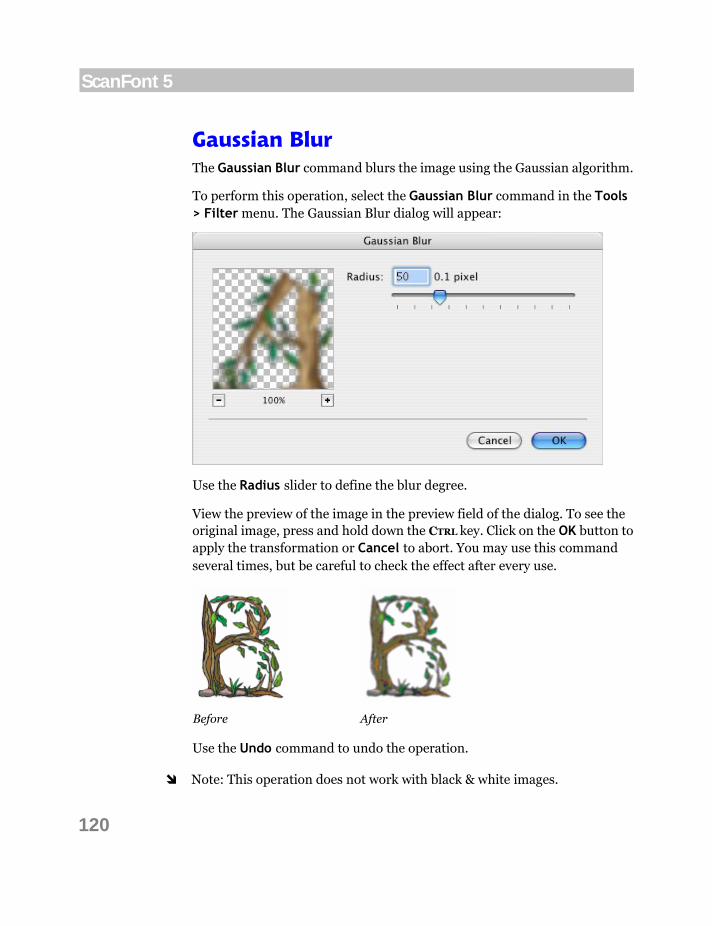
120
ScanFont 5
Gaussian Blur The Gaussian Blur command blurs the image using the Gaussian algorithm.
To perform this operation, select the Gaussian Blur command in the Tools > Filter menu. The Gaussian Blur dialog will appear:
Use the Radius slider to define the blur degree.
View the preview of the image in the preview field of the dialog. To see the original image, press and hold down the CTRL key. Click on the OK button to apply the transformation or Cancel to abort. You may use this command several times, but be careful to check the effect after every use.
Before After
Use the Undo command to undo the operation.
Note: This operation does not work with black & white images.

121
Advanced Image Editing
Enhance The Enhance command tries to detect unwanted pixels and remove them. It is similar to the Reduce Noise command described later as it reduces noise, thus improving the image appearance.
To enhance the image, select the Enhance command in the Tools > Filter menu. The Enhance dialog will appear:
Use the Level slider to define the degree of unwanted pixels to remove. This filter is good for scanned black & white images too. See also the examples of the Custom Filter usage described later on page 126.
You will see the preview of the image in the preview field of the dialog. To see the original image, press and hold down the CTRL key. You can use this command several times, but be careful to check the effect after every use.
Before After
Use the Undo command to undo the operation.

122
ScanFont 5
Reduce Noise The Reduce Noise operation makes the image less noisy.
To apply this operation, select the Tools > Filter > Reduce Noise command. The Reduce Noise dialog will appear:
Enter the Threshold method, amount and the Area value in square pixels to define the best transformation parameters. View the preview of the image in the preview field of the dialog. To see the original image, press and hold down the CTRL key.
The Threshold by parameters work the same way as the Threshold operation.
Click on the OK button to apply the transformation or Cancel to abort.
This operation can clean up the image and even make it empty. You may use the Reduce Noise command several times to achieve the best result.

123
Advanced Image Editing
Median Noise The Median Noise operation makes the image more or less noisy by averaging the colors of neighbor pixels.
To apply this operation, select the Tools > Filter > Median Noise command. The Median Noise dialog will appear:
Enter the Radius value for pixel color averaging. You will see the preview of the image in the preview field of the dialog. To see the original image, simply press and hold down the CTRL key.
Click on the OK button to apply the transformation or Cancel to abort.
Before After
Use the Undo command to undo the operation.
You can use the Median Noise command multiple times to achieve the result you need.

124
ScanFont 5
Sharpen This command makes the image sharper and higher contrast. It is the opposite of the Soften command described on page 125.
To apply this operation, select the Tools > Filter > Sharpen command. The Sharpen dialog will appear:
Enter the Level value of sharpness. View the preview of the image in the preview field of the dialog. To see the original image, press and hold down the CTRL key.
Click on the OK button to apply the transformation or Cancel to abort.
Before After
Use the Undo command to undo the operation.
You may use the Sharpen operation several times to achieve the best result.
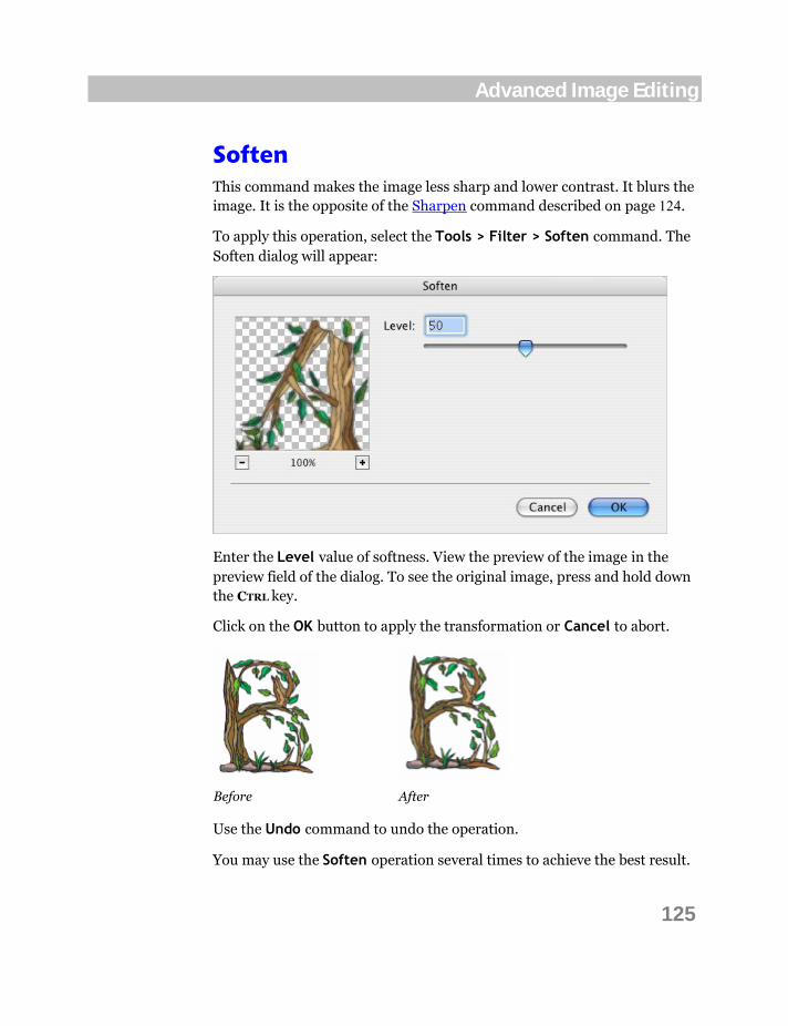
125
Advanced Image Editing
Soften This command makes the image less sharp and lower contrast. It blurs the image. It is the opposite of the Sharpen command described on page 124.
To apply this operation, select the Tools > Filter > Soften command. The Soften dialog will appear:
Enter the Level value of softness. View the preview of the image in the preview field of the dialog. To see the original image, press and hold down the CTRL key.
Click on the OK button to apply the transformation or Cancel to abort.
Before After
Use the Undo command to undo the operation.
You may use the Soften operation several times to achieve the best result.

126
ScanFont 5
Custom Filter The Custom Filter command will allow you to make many transformations that are not included in the Tools > Filter menu as individual commands. It is harder to use than the commands described before, but it can produce very interesting effects on images. The Custom Filter is based on a predefined mathematical operation known as “convolution”, where each pixel is reassigned a value based on the values of surrounding pixels.
This command selection will bring up the Custom Filter dialog:
You will see ten text boxes in which to enter values. They are arranged as a square 3 by 3 matrix plus a scale factor. When you enter the Matrix values the Scale factor will automatically change, reflecting the matrix values sum. Use the Scale slider to change the factor; examine the preview to the left; then click on OK to apply the filter, or Cancel to dispose of the dialog.
To see the original image, press and hold down the CTRL key. Of course you can undo this operation by using the Undo command.

127
Advanced Image Editing
Take some time to experiment with this filter. We will show you some examples here:
Original image Filter values applied Result image
As you can see the parameters in the last example allow you to perfect the image by removing unwanted black pixels outside and white holes inside the glyph’s shape. This is a more general case of the Enhance operation described on page 121.
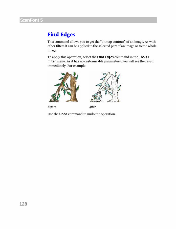
128
ScanFont 5
Find Edges This command allows you to get the "bitmap contour" of an image. As with other filters it can be applied to the selected part of an image or to the whole image.
To apply this operation, select the Find Edges command in the Tools > Filter menu. As it has no customizable parameters, you will see the result immediately. For example:
Before After
Use the Undo command to undo the operation.
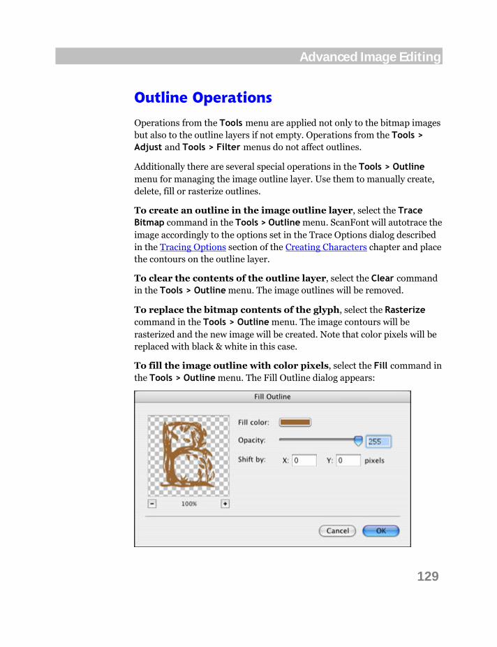
129
Advanced Image Editing
Outline Operations
Operations from the Tools menu are applied not only to the bitmap images but also to the outline layers if not empty. Operations from the Tools > Adjust and Tools > Filter menus do not affect outlines.
Additionally there are several special operations in the Tools > Outline menu for managing the image outline layer. Use them to manually create, delete, fill or rasterize outlines.
To create an outline in the image outline layer, select the Trace Bitmap command in the Tools > Outline menu. ScanFont will autotrace the image accordingly to the options set in the Trace Options dialog described in the Tracing Options section of the Creating Characters chapter and place the contours on the outline layer.
To clear the contents of the outline layer, select the Clear command in the Tools > Outline menu. The image outlines will be removed.
To replace the bitmap contents of the glyph, select the Rasterize command in the Tools > Outline menu. The image contours will be rasterized and the new image will be created. Note that color pixels will be replaced with black & white in this case.
To fill the image outline with color pixels, select the Fill command in the Tools > Outline menu. The Fill Outline dialog appears:
130
ScanFont 5
Select color and opacity level, enter the values of horizontal and/or vertical shift if needed, and click on the OK button. The interior of the outline will be filled with the selected color with antialiasing. This operation preserves the original pixels of the image that lay outside of the contours.
All the above outline operations can be applied to the whole image in the Image window or to the selection.
Note: The content of the outline layer can be saved to the disk only in ScanFont document (.sf) format, or it can be exported to outline-editing application.

ScanFont User Interface
Before talking about images, fonts and the ScanFont features, let’s spend some time learning the ScanFont user interface.
The user interface of ScanFont is highly customizable. This chapter discusses how you can custom-tailor the ScanFont interface so it fits your needs best. Note that throughout the book, we will refer to menu commands, toolbar buttons and keyboard shortcuts as they appear in the default user interface settings of ScanFont, so keep this in mind if you have customized their location or appearance.
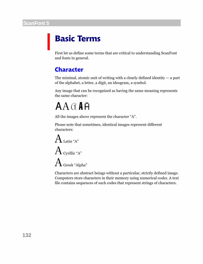
132
ScanFont 5
Basic Terms
First let us define some terms that are critical to understanding ScanFont and fonts in general.
Character The minimal, atomic unit of writing with a clearly defined identity — a part of the alphabet, a letter, a digit, an ideogram, a symbol.
Any image that can be recognized as having the same meaning represents the same character:
All the images above represent the character “A”.
Please note that sometimes, identical images represent different characters:
Latin “A”
Cyrillic “A”
Greek “Alpha”
Characters are abstract beings without a particular, strictly defined image. Computers store characters in their memory using numerical codes. A text file contains sequences of such codes that represent strings of characters.
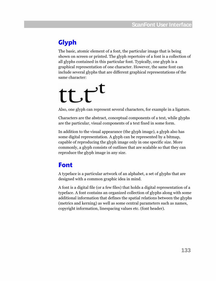
133
ScanFont User Interface
Glyph The basic, atomic element of a font, the particular image that is being shown on screen or printed. The glyph repertoire of a font is a collection of all glyphs contained in this particular font. Typically, one glyph is a graphical representation of one character. However, the same font can include several glyphs that are different graphical representations of the same character:
Also, one glyph can represent several characters, for example in a ligature.
Characters are the abstract, conceptual components of a text, while glyphs are the particular, visual components of a text fixed in some form.
In addition to the visual appearance (the glyph image), a glyph also has some digital representation. A glyph can be represented by a bitmap, capable of reproducing the glyph image only in one specific size. More commonly, a glyph consists of outlines that are scalable so that they can reproduce the glyph image in any size.
Font A typeface is a particular artwork of an alphabet, a set of glyphs that are designed with a common graphic idea in mind.
A font is a digital file (or a few files) that holds a digital representation of a typeface. A font contains an organized collection of glyphs along with some additional information that defines the spatial relations between the glyphs (metrics and kerning) as well as some central parameters such as names, copyright information, linespacing values etc. (font header).

134
ScanFont 5
Encoding When the user presses a key (or a combination of keys) on a keyboard, a numerical code is stored in the computer’s memory. This code represents a character, an abstract unit of writing. A series of such codes forms a string of text.
Every keystroke stands for a different character, so every character uses a different numerical code (also called codepoint). Operating systems and applications need to know which number represents what character — otherwise a spelling checker couldn’t recognize words that you’re typing. So each operating system and each application uses a list that maps characters to numerical codes. This mapping is called “text encoding”. In the past, different computers used different text encoding standards (so-called codepages), so that the letter “Ä” was stored as number 142 in one program and as number 128 in another program. Modern operating systems and applications encode text using the international Unicode Standard, which assigns a unique numerical codepoint to every character used in writing by humankind. In Unicode, “Ä” always uses the code U+00C4 (which is hexadecimal for 196).
Whenever the text is printed or displayed on the screen, the computer looks inside the font file and finds out which character codes correspond to which glyphs, so that the series of abstract character codes can be visualized using some specific images of letters, digits and other symbols. Every font includes a mapping of character codes to glyphs — this mapping is called the “font encoding” (sometimes, “encoding vector”, or, in this manual, just “encoding”). These days, most font formats use the Unicode Standard as basis for their font encoding, but it is possible to produce fonts that are encoded using the older codepages. It is even possible to have several different encoding vectors in one font, so that both old and modern applications can work with it.

135
ScanFont User Interface
Some More Definitions Advance width the distance between the left and right margins (sidebearings) of a glyph. Sometimes it is called glyph width.
Alphabet/Script the collection of characters used to write a particular language. “The” alphabet (as North Americans and English know it) is the script for the English language; Latin script is the script for most European, South American and some Asian languages. Cyrillic script is used in all Slavonic languages (Russian, Ukrainian, Serbian, Bulgarian and many others). Note that a script usually includes many more characters than necessary for the one language. Latin script, for example, includes more than 200 characters.
BMP the standard graphics file format on Windows-compatible computers.
EPS Encapsulated PostScript. Image file format that supports both vector graphics and bitmap images.
FontLab format see VFB format
GIF Graphic Interchange Format. A common format for image files often used on the WWW. Resolution is limited to 256 colors.
OpenType OpenType font format, jointly developed by Microsoft and Adobe. OpenType fonts can be TrueType-flavored (we call them OpenType TT fonts) and PostScript-flavored (OpenType PS fonts). Both are Unicode-encoded and support special features like swashes, contextual forms, ligatures etc.
PICT The native graphic file format for Macintosh images. A PICT file may contain black and white, grayscale, or color information.
PNG Portable Network Graphics. A standard graphics file format designed for WWW to replace the GIF file format.
136
ScanFont 5
RGB the color model in which red, green and blue are combined in various ways to reproduce other colors on the monitor.
TIFF Tagged Image File Format An uncompressed image file format for PC and Macintosh.
Transparency additional information in color images allowing color pixels to be more or less transparent so the background becomes partially visible.
TrueType a font format using quadratic b-spline mathematics to describe glyph outlines. Developed and promulgated by Microsoft and Apple Computer. We use the term Windows TrueType/OpenType TT for Windows TrueType fonts here in the Manual. Windows TrueType fonts containing embedded bitmaps are called OpenType SBIT fonts.
Type 1 (Adobe Type 1, PostScript Type 1) a font format using cubic b-spline mathematics to describe glyph outlines. Developed and promulgated by Adobe Systems.
Unicode range the portion of Unicode dealing with a particular language or script. E.g. the Hebrew range, the Cyrillic range, the extended Latin range. A Unicode range is not limited to 256 characters. It is usually a contiguous part of Unicode.
VFB format the internal outline font format of Fontlab products.
137
ScanFont User Interface
Customizing ScanFont’s User Interface
As you may infer from the title of this section some of the ScanFont user interface (which means windows and keyboard shortcuts) are customizable. We believe our default interface is the easiest to use, but if for some reason you do not like it, you are free to make any changes you want. If you do not want to change anything in the ScanFont user interface, you can fast forward to the next section.
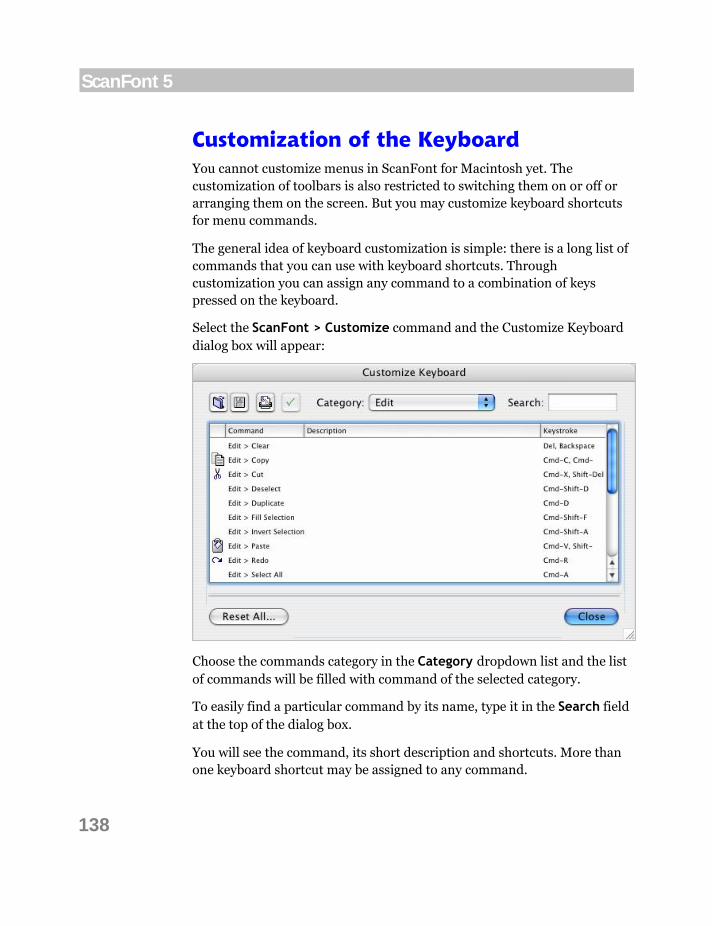
138
ScanFont 5
Customization of the Keyboard You cannot customize menus in ScanFont for Macintosh yet. The customization of toolbars is also restricted to switching them on or off or arranging them on the screen. But you may customize keyboard shortcuts for menu commands.
The general idea of keyboard customization is simple: there is a long list of commands that you can use with keyboard shortcuts. Through customization you can assign any command to a combination of keys pressed on the keyboard.
Select the ScanFont > Customize command and the Customize Keyboard dialog box will appear:
Choose the commands category in the Category dropdown list and the list of commands will be filled with command of the selected category.
To easily find a particular command by its name, type it in the Search field at the top of the dialog box.
You will see the command, its short description and shortcuts. More than one keyboard shortcut may be assigned to any command.

139
ScanFont User Interface
Editing Keystrokes
To assign, remove or edit a shortcut for the command, select it in the list
and click on the button or double-click on the command in the list. The Edit Keystrokes dialog will appear:
Here you can see the list of keyboard shortcuts currently defined for that
command. The button at the right of the list allows removal of one of the existing shortcuts.
To define a new keyboard shortcut, position the cursor on the editing field below the New Keystroke label. When the editing field has focus press the combination of keys that you want to assign. A description of that combination will appear in the editing field and you can click on the Assign
button to assign that combination to the command. The keystroke will be added to the list.
Click on OK to finish editing the command shortcuts.
Note: The CTRL key is not allowed and is not accepted.

140
ScanFont 5
Printing the List of Commands
You can print the list of commands, their descriptions and shortcuts. To print the list, choose the appropriate category in the Category dropdown
list and click on the button at the top of the Customize Keyboard dialog box.
To print all available commands, select All Commands in the Category dropdown list.
Exporting and Importing Commands
To export the list of commands with their descriptions and shortcuts,
click on the button at the top of the Customize Keyboard dialog box. ScanFont will ask you for the file name and destination. Name the file and click Save.
The exported file is a plain text file with tab-delimited fields (.cvs) that can be edited in any text editor or MS Excel application. You may edit it or put somewhere on your hard disk for backup purposes.
To import the list of commands from the previously exported .cvs file,
click on the button at the top of the Customize Keyboard dialog box. Choose the file and click Open in the standard File Open dialog. The shortcuts from the file will replace the current shortcuts.
To reset all changes back to ScanFont defaults, click on the Reset All button.
Click on the Close button at the bottom after you finish customizing the keyboard shortcuts to close the dialog box.

141
ScanFont User Interface
ScanFont Options
This section is very important since it is referenced from many other sections of the Manual.
Most of the features, behavior, import and export algorithms of ScanFont are customizable in the Preferences dialog box. We encourage you to experiment with the settings and adapt them to your preferences. However, note that the authors have carefully chosen the factory settings so if you do not feel like poking around the Preferences in most cases you will be fine with the defaults.
To open the Preferences dialog box, select the Preferences command in the ScanFont menu:
The dialog structure is quite simple. There is a list of pages combined in categories on the left, the contents of the currently selected page on the right and some buttons on the bottom. You will notice that the structure of this dialog bears resemblance to the structure of the Font Info dialog.
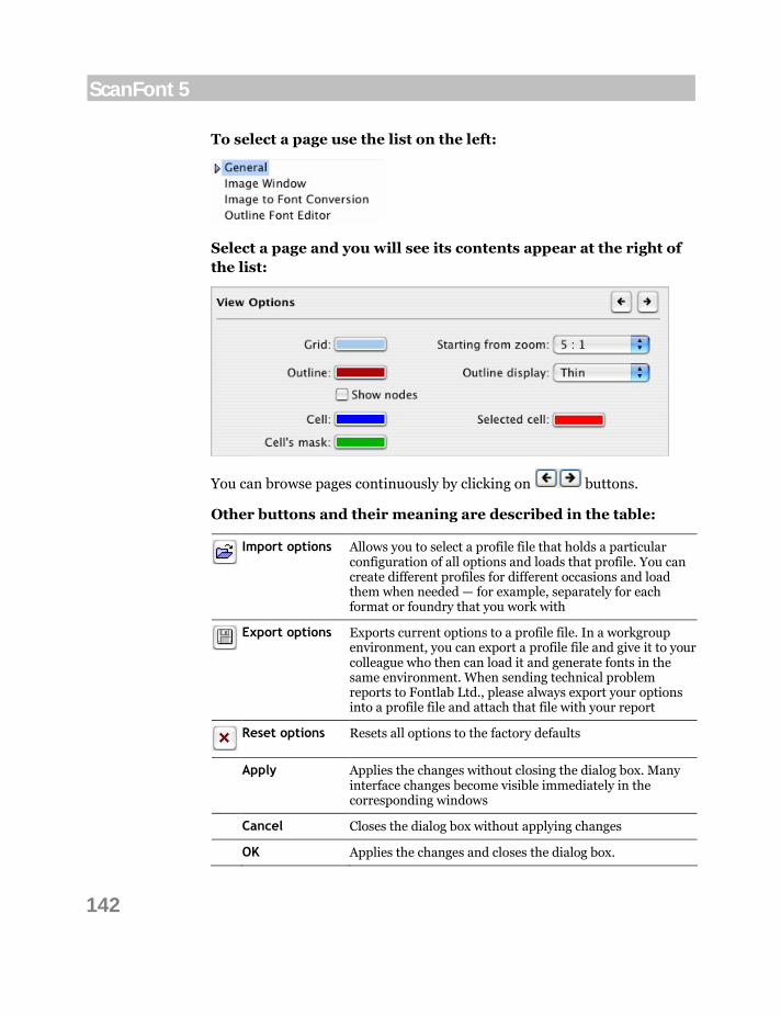
142
ScanFont 5
To select a page use the list on the left:
Select a page and you will see its contents appear at the right of the list:
You can browse pages continuously by clicking on buttons.
Other buttons and their meaning are described in the table:
Import options Allows you to select a profile file that holds a particular
configuration of all options and loads that profile. You can create different profiles for different occasions and load them when needed — for example, separately for each format or foundry that you work with
Export options Exports current options to a profile file. In a workgroup
environment, you can export a profile file and give it to your colleague who then can load it and generate fonts in the same environment. When sending technical problem reports to Fontlab Ltd., please always export your options into a profile file and attach that file with your report
Reset options Resets all options to the factory defaults
Apply Applies the changes without closing the dialog box. Many interface changes become visible immediately in the corresponding windows
Cancel Closes the dialog box without applying changes
OK Applies the changes and closes the dialog box.
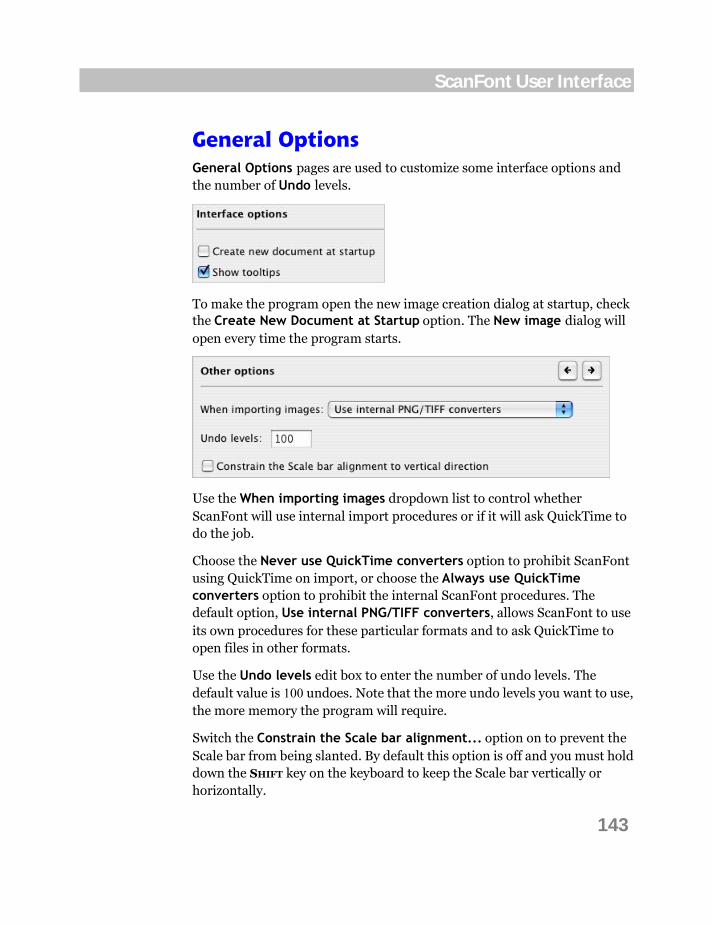
143
ScanFont User Interface
General Options General Options pages are used to customize some interface options and the number of Undo levels.
To make the program open the new image creation dialog at startup, check the Create New Document at Startup option. The New image dialog will open every time the program starts.
Use the When importing images dropdown list to control whether ScanFont will use internal import procedures or if it will ask QuickTime to do the job.
Choose the Never use QuickTime converters option to prohibit ScanFont using QuickTime on import, or choose the Always use QuickTime converters option to prohibit the internal ScanFont procedures. The default option, Use internal PNG/TIFF converters, allows ScanFont to use its own procedures for these particular formats and to ask QuickTime to open files in other formats.
Use the Undo levels edit box to enter the number of undo levels. The default value is 100 undoes. Note that the more undo levels you want to use, the more memory the program will require.
Switch the Constrain the Scale bar alignment... option on to prevent the Scale bar from being slanted. By default this option is off and you must hold down the SHIFT key on the keyboard to keep the Scale bar vertically or horizontally.

144
ScanFont 5
Image Window Options The Image Window page is used to customize the view and behavior of the Image window.
View Options
You can change colors for some elements of the Image window. Click on the corresponding color rectangles to change the color for grid, outlines and cells.
Grid
The gridlines are not part of the transparency grid. They delimit pixels in all color modes when large zooming is selected:
Red grid lines
Select the starting zoom mode when the grid becomes visible.

145
ScanFont User Interface
Outline
Besides the color of outline contours you can choose to Show nodes and/or to show outline Thin or Thick:
Thin outline with nodes shown Thick outline without nodes shown
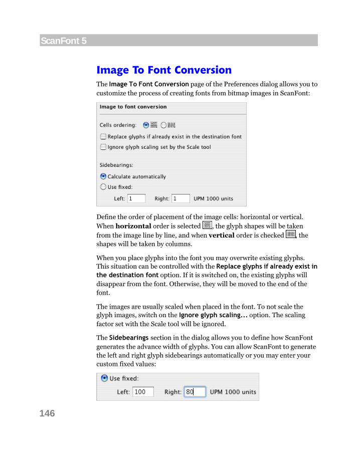
146
ScanFont 5
Image To Font Conversion The Image To Font Conversion page of the Preferences dialog allows you to customize the process of creating fonts from bitmap images in ScanFont:
Define the order of placement of the image cells: horizontal or vertical. When horizontal order is selected , the glyph shapes will be taken from the image line by line, and when vertical order is checked , the shapes will be taken by columns.
When you place glyphs into the font you may overwrite existing glyphs. This situation can be controlled with the Replace glyphs if already exist in the destination font option. If it is switched on, the existing glyphs will disappear from the font. Otherwise, they will be moved to the end of the font.
The images are usually scaled when placed in the font. To not scale the glyph images, switch on the Ignore glyph scaling... option. The scaling factor set with the Scale tool will be ignored.
The Sidebearings section in the dialog allows you to define how ScanFont generates the advance width of glyphs. You can allow ScanFont to generate the left and right glyph sidebearings automatically or you may enter your custom fixed values:
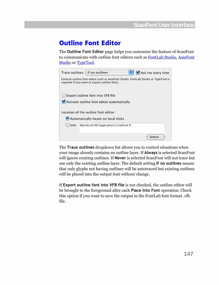
147
ScanFont User Interface
Outline Font Editor The Outline Font Editor page helps you customize the feature of ScanFont to communicate with outline font editors such as FontLab Studio, AsiaFont Studio or TypeTool.
The Trace outlines dropdown list allows you to control situations when your image already contains an outline layer. If Always is selected ScanFont will ignore existing outlines. If Never is selected ScanFont will not trace but use only the existing outline layer. The default setting If no outlines means that only glyphs not having outlines will be autotraced but existing outlines will be placed into the output font without change.
If Export outline font into VFB file is not checked, the outline editor will be brought to the foreground after each Place Into Font operation. Check this option if you want to save the output in the FontLab font format .vfb file.

148
ScanFont 5
Switch on the Ask me every time option to make ScanFont present the following dialog during each Place Into Font operation (if any outlines present):
Check the appropriate check box and proceed by clicking on the Export button. Clicking on Cancel will stop the Place Into Font operation.
You can make these options permanent for the current image by setting the Always apply these settings for current document check box. In this case ScanFont will remember your choice and will not produce this dialog until you hold down the CTRL key on the keyboard while choosing the Place Into Font command.
If ScanFont cannot locate any outline font editor in your system or fails to communicate with a particular version of the server application, select the application manually by clicking on the Select button and choosing it. You will see the full path to the selected application in the corresponding field.

149
Index
Index
A advance width, 146 AICB option, 19 Append, 129 AsiaFont Studio, 65 autosplitting, 45
customizing, 49
B background
removing, 42 baseline, 59
aligning, 45 editing, 45 moving, 45
bounding box, 45 brush
angle, 31, 100 diameter, 31, 100 hardness, 31, 100 roundness, 31, 100
Brush tool, 31, 100 Brushes Panel, 31, 100
C canvas size, 26 Cell tool, 51 cells
defining, 45 exporting, 64 mask, 51 merging, 45 splitting, 45
Color Palette, 94
Custom Filter, 126
D Define Cell Tool, 51
E Ellipse tool, 36, 102 Emboss, 118 Enhance, 121 EPS, 19 Eraser tool, 100
F Fill tool, 101 Find Edges, 128 FontLab, 65 FreeHand, 19
G Gaussian Blur, 120 glyph
advance width, 146 drawing, 94 names, 64
I Illustrator, 19 image
conversion, 146 size, 26 splitting, 45
Image Window, 45
K keyboard shortcuts, 51, 139

150
ScanFont 5
customization, 138 defining, 139 exporting and importing, 140 printing, 140
Knife tool, 51
L Line tool, 101
M Magic Wand tool, 90 Median Noise, 123
O Opaque mode, 92 operation
Custom Filter, 126 Emboss, 118 Enhance, 121 Find Edges, 128 Gaussian Blur, 120 Median Noise, 123 Reduce Noise, 122 Rotate, 40 Sharpen, 124 Smart Blur, 119 Soften, 125
outline, 19 creating, 129 deleting, 129 filling with color, 129 rasterizing, 129
outline font editor, 65 outlines, 45
P Pencil tool, 100 pixel size, 26 Pixels
tracing, 129 Polygon tool, 102 Preparation of the Source Image, 16
R Rectangle tool, 36, 102 Reduce Noise, 122 resampling, 26 resolution
changing, 26 Rotate, 40
S scale bar, 56 scale factor, 56 Select Region tool, 89 Select tool, 29, 88 Selecting, 104 selection
copying, 30, 91 deleting, 93 moving, 30, 91
Sharpen, 124, 125 sidebearing, 146 Smart Blur, 119 Soften, 124, 125 splitting
editing, 51 splitting data
saving and restoring, 55
T Tablet Options, 31, 100 Text tool, 103 Tool Options panel, 31, 86, 90, 92, 100 toolbar
Tools, 51 transparency, 92 Transparent mode, 92 TypeTool, 65
U Unicode, 64